Embed Size (px)
Citation preview

Riverside CountyPerris, California
SPECIFICATION NO. 1368W
Redlands and Cottonwood Booster Electrical Replacement
Work Order # 419488
A PUBLIC WORKS PROJECT
Contents:
Specifications | Notice Inviting Bids | Bidding Requirements | Bid Forms | Contract Forms | Conditions of Contract
Joe Mouawad, P.E. - General Manager
Safety is of paramount and overriding importance toEastern Municipal Water District
Visit our website at www.emwd.org to view currently advertised projectsNavigate to Construction Construction Bid Opportunities

[PAGE LEFT INTENTIONALLY BLANK]

TABLE OF CONTENTS
BIDDING REQUIREMENTS PAGE 00000 Title Page 00010 Table of Contents 00012 Notice Inviting Bids NIB-1 thru NIB-6 00016 Bid Walk-thru Map/Directions 00018 Instructions to Bidders B-1 thru -6 00020 Bidding Sheets & Equipment & Material List (submit with bid) BS-1 thru -6 00024 Proposal (7 day) (submit with bid) C3-1 thru -2 00028 Designation of Subcontractors (submit with bid) C5a thru e 00030 Contractor's Licensing Statement (submit with bid) C6-1 thru -2 00032 Non-Collusion Declaration (submit with bid) C7-1 thru -2 00034 Agreement C8a thru b 00036 Performance Bond C9-1 thru -4 00038 Payment Bond C-10-1 thru -4 00040 Bid Bond (submit with bid) BB-1 thru -2 00042 Worker’s Compensation Insurance Certificate C11-1 thru -2 00044 Certificate of Insurance Sample C12 00046 Iran Contracting Act Certification (submit with bid if over $1million) C13-1 thru -4 00050 Cal-OSHA form 300A (submit with bid) C16-1 thru -2 00052 Contractor’s Cal Osha Compliance History and SIC Code (submit with bid) C17-1 thru -2 00056 Employee Safety & Health Training Records C19-1 thru -2 00057 Contractor Registration Extract(s) (submit with bid) C22-1 thru -2 00058 Contractor’s Proof of Insurance Certificate (submit with bid) C23-1 thru -2 GENERAL CONDITIONS PAGE 00062 Section E, Inspection & Tests E-1 thru E-2 00064 Section F, Labor & Construction F-1 thru F-60
Includes Exhibit A – Escrow Agreement 00066 Section H, Permits H-1 thru H-2 SPECIAL CONDITIONS PAGE 00100 Special Conditions SC-1 thru SC-16
CONTRACT DRAWINGS 00200 Section P Standard & Construction Drawings (list) P-1 thru P-2 EMWD DETAILED PROVISIONS 01000 General Safety Requirements 1 thru 10 01026 Schedule of Values 1 thru 4 01185 Work Restrictions and Sequence of Work (Custom) 1 thru 12

01310.1 Project Control Schedule - Small Project 1 thru 12 01381 Pre-construction Audio/Video Taping: Above Ground Facilities 1 thru 4 01430 Operation and Maintenance Data (Custom) 1 thru 10 01500 Temporary Facilities and Controls (Custom) 1 thru 4 02050 Demolition and Salvage 1 thru 2 02201 Construction Methods and Earthwork 1 thru 26 02210 Site Grading 1 thru 8 02221 Trenching, Backfilling, and Compacting 1 thru 10 02444 Chain Link Fencing 1 thru 6 03150 Formwork 1 thru 6 03200 Reinforcing 1 thru 6 03300 Cast-in-Place Concrete 1 thru 38 04220 Concrete Unit Masonry 1 thru 12 07920 Sealants and Caulking 1 thru 6 08711 Locksets and Hardware 1 thru 2 09900 Painting and Protective Coatings 1 thru 48 15064 Plastic (PVC) Water Pipe and Fittings 1 thru 4 15700 HVAC Equip 1 thru 22 16010 General Electrical Requirements 1 thru 28 16040 Short-Circuit/Coordination Study and Arc-Flash Hazard Study 1 thru 26 16050 Basic Electric Materials and Methods 1 thru 60 16150 Induction Motors 1 thru 22 16160 AC Variable Frequency Drives 1 thru 30 16250 Automatic Transfer Switch 1 thru 14 16480 Motor Control Centers, Switchboards, and Panelboards 1 thru 62 16620 Emergency Standby Generators (Custom) 1 thru 20 16950 Custom Control Panels 1 thru 30 17005 General Instrumentation and Controls Requirements 1 thru 32 17010 Programmable Logic Controller 1 thru 32
APPENDICES (Provided on Flash Drive)
Appendix A Approved Materials List Appendix B SCE Service Plans Appendix C CAM 17 Coating Analysis Appendix D Shutdown Coordination Table Appendix E Redlands and Cottonwood Booster Record Drawings Appendix F Asbestos Test Results Appendix G Emergency Standby Generator Sizing Report Appendix H Cable Tray Weight/Fill Calculations & Structural Load Assessment Appendix I Pump Curve for Pump No. 4 Appendix J Subsurface Utility Report

NIB-1 00012 Notice Inviting Bid
EASTERN MUNICIPAL WATER DISTRICT SPECIFICATION NO. 1368W
REDLANDS AND COTTONWOOD BOOSTER ELECTRICAL REPLACEMENT NOTICE INVITING BID NIB-1. Receipt of Bids. Electronic proposals (bids) for this project to be emailed to [email protected] no later than 5:00 p.m., TUESDAY, OCTOBER 19, 2021. Original Bid Bond and attachments to be mailed to the District within that week. You are NOT to drop them off at the District. Bids will not be publicly opened. The Preliminary Bid Summary will be posted on the website www.emwd.org no later than 10:00 a.m. the next day. Fed Ex Bid Bond to: EMWD, 2270 Trumble Road, Perris, CA, 92570 Mail Bid Bond to: EMWD, P O Box 8300, Perris, CA 92572-8300 All bids submitted will become the property of EMWD and subject to disclosure under the Public Records Act. All bids will be posted on the website www.emwd.org approximately 10 days from bid opening. NIB-2. Prequalification. Due to the special requirements of the project, the DISTRICT has performed a public invitation to pre-qualify bidders for the project. Only firms that have pre-qualified shall be entitled to submit a bid for this project. LIST OF PREQUALIFIED GENERAL CONTRACTORS ELIGIBLE TO BID
COMPANY/ADDRESS/PHONE CONTACT & EMAIL
Baker Electric, Inc. 1298 Pacific Oaks Place Escondido, CA 92029
Melanie Bisher Ph: (760) 745-2001 Fax: (760) 745-0321 Email: [email protected]

NIB-2 00012 Notice Inviting Bid
COMPANY/ADDRESS/PHONE CONTACT & EMAIL
CDM Constructors, Inc. 9220 Cleveland Ave., Suite 100 Rancho Cucamonga, CA 91730
Steven A. Kurtz Ph: (909) 579-3469 Fax: (909) 980-5185 Email: [email protected]
CSI Electrical Contractors, Inc. 10623 Fulton Wells Avenue Santa Fe Springs, CA 90670
Mike Denning Ph: (562) 946-0700 Fax: (562) 946-0701 Email: [email protected]
Davis Electric, Inc. 13556 Douglas St. Yucaipa, CA 92399
Wayne Davis Ph: (909) 446-0054 Fax: (909) 446-0366 Email: [email protected]
Leed Electric, Inc. 13138 Arctic Circle Santa Fe Springs, CA 90670
Seyed A. Jamali Dinan Ph: (562) 270-9500 Fax: (562) 863-5723 Email: [email protected]
Mass. Electric Construction Co. 1925 Wright Avenue, Suite C La Verne, CA 91750
Brandon Parker Ph: (909) 962-6001 Email: [email protected]
Southern Contracting Company 559 N. Twin Oaks Valley Rd. San Marcos, CA 92069
Philip E. Waterman Ph: (760) 744-0760 Fax: (760) 744-9691 Email: [email protected]
NIB-3. Contract Documents. The contract documents, which include instructions to bidders, plans and specifications, are available at www.emwd.org. To view and download these documents, navigate to Construction and select Construction Bid Opportunities. If obtaining the contract documents online, please complete the Planholder Registration form to receive email notification of addenda issued. Bidders shall use full size drawings to prepare bid.

NIB-3 00012 Notice Inviting Bid
NIB-4. Location and Description of Work. The work to be constructed is located on 13400 Redlands Blvd, Moreno Valley, CA. The work comprises providing temporary power during construction, including a temporary portable MCC with (2) 100 HP VFDs and a portable generator and RTU/MCP panel; removal of existing electrical equipment to be replaced; construction of SCE Metering Switchboard; construction of 800 Amp Distribution Switchboard; construction of 800 Amp automatic transfer switch (ATS) and emergency standby generator; construction of new motor for Pump # 4; construction of four (4) VFDS; construction of a new RTU/MCP Panel, and installation of EMWD provided OIT and RTU backplane and appurtenances; construction of new cable trays, conduits and wiring. Installing XHHW-2 type conductors for power and control cables; and construction of site improvements including chain-link fencing, gates, and concrete slabs. NIB-5. Mandatory Pre-Bid Walk-Through will be conducted by EMWD on TUESDAY, SEPTEMBER 28, 2021 at 9:00 a.m. If you would like to attend the walk-thru email Melissa Abella [email protected] to be added to the list of attendees. Walk-thru will be held at 13400 Redlands Blvd, Moreno Valley, CA 92555 (see Pre-Bid Walk Thru map/directions). Please arrive promptly! All bidders must have an employee of their firm sign-in and attend the mandatory pre-bid walk-through meeting. Failure to do so shall deem your bid non-responsive. Personal Protective Equipment (PPE). For your safety, attendees shall bring and wear hard hats, safety vests, and close-toed shoes, if construction is present. QUESTIONS: All questions must be submitted in writing by 5:00 p.m., FRIDAY, OCTOBER 1, 2021 to Mr. Edward Serna c/o Melissa Abella; EMAIL: [email protected] & [email protected] Questions received after this time may not be responded to. NIB-6. Contract Bonds. All bonds shall be executed by admitted surety insurers, as defined in Code of Civil Procedure section 995.120. Each proposal must be accompanied by a certified check or satisfactory surety bond (by utilizing the District’s Bid Bond form BB-1) for not less than 10% of the bidder's total contract price as a guarantee that the bidder shall, within seven (7) days after the mailing of a notice of acceptance of bid by the District to the bidder, enter into the written contract supplied by the District. The District shall return the bid bond, upon request. The Contractor shall furnish a faithful performance bond in an amount equal to 100% of the amount of the contract and a labor payment bond in an amount equal to 100% of the contract amount. Pursuant to Section 995.660(a) of the Code of Civil Procedure, the Contractor shall submit the following documents with the performance and payment bonds:
NIB-4 00012 Notice Inviting Bid
(1) The original, or a certified copy, of the unrevoked appointment, power of attorney, bylaws, or other instrument entitling or authorizing the person who executed the bond to do so;
(2) A certified copy of the certificate of authority of the insurer issued by the State of California’s Insurance Commissioner; and
(3) Copies of the insurer's most recent annual and quarterly statements filed with the Department of Insurance.
NO PAYMENT SHALL BE MADE UNTIL THE BONDS ARE APPROVED BY THE DISTRICT NIB-7. Safety. Safety of all activities in connection with the work is of paramount and overriding importance to the District. The District is recognized by the California Occupational Safety and Health Administration (Cal OSHA) as an active participant in the California Voluntary Protection Program (Cal VPP). The District is designated a Cal STAR site due to our high-level commitment to safety. Bidders on this project will be required to comply with and meet all applicable Cal OSHA requirements of Title 8 of the California Code of Regulations, including their current Injury and Illness Prevention Plan, T8 CCR Section 3203. All bidders shall complete the C-16 Annual Summary of Work Related Injuries and Illness (Cal/OSHA Form 300A) and the C-17 Contractor’s Cal/OSHA Compliance History and SIC Code form. Failure to fully divulge, complete and submit these forms may deem your bid non-responsive A safety conference shall be scheduled prior to the preconstruction conference to review the experience modification rating, the respective safety requirements, and to discuss implementation of all health and safety provisions related to this project. NIB-8. Contract Time. No bid or bid security may be withdrawn for seventy-five (75) calendar days after the date bids are received. The successful bidder shall, within seven (7) calendar days after the District mails a notice of acceptance of bid, return the signed agreement and bonds, and attend the pre-construction conference at the District office. The contract period shall commence seven (7) calendar days from the date of the Notice-of-Acceptance-of-Proposal. The Contractor shall complete all work, including testing, within four hundred thirty (430) calendar days.
NIB-9. Contractor Classification. Bidders on this work will be required to be licensed by the State of California as Classification A - General Engineering Contractor or a Classification C-10 Electrical Contractor at the time of the bid and at the time of award as such license is defined in Section 7056 and/or Section 7058 of the Business and Professional Code and Section 732 of the California Administrative Code.

NIB-5 00012 Notice Inviting Bid
NIB-10. Non-Discrimination. Bidders on this work will be required to comply with the provisions of the California Labor Code and with the President's Executive Order No. 11246 and supplements thereto. The requirements for bidders and contractors under this order are explained in the specifications. NIB-11. Minimum Wages. In accordance with the provisions of the California Labor Code, the Director of Industrial Relations has ascertained the general prevailing rates of wages and the general prevailing rates for legal holiday and overtime work in Riverside County (refer to Section F-General Conditions). Copies of said rates are on file at the office of the District, which copies shall be made available for review to any interested party on request. The successful bidder shall post a copy of such determinations at the jobsite. NIB-12. Public Works Requirements California Administrative Code, Title 8, Group 3, Section 16100 apply, which are/include:
A. all applicable requirements of sections 1771, 1774 - 1776, 1813, and 1815. B. the appropriate number of apprentices are on the job site, as set forth in Labor Code
Section 1777.5. C. workers' compensation coverage, set forth in Labor Code Sections 1860 and 1861. D. to keep accurate records of the work performed on the public works project, as set
forth in Labor Code Section 1812. E. inspection of payroll records pursuant to Labor Code Section 1776, and as set forth in
Section 16400 (e) of these regulations. F. and other requirements imposed by law.
NIB-13. Public Works Contractor and Subcontractor Registration. This project is subject to compliance monitoring and enforcement by the Department of Industrial Relations. No contractor or subcontractor may be listed on a bid proposal or be awarded a contract for a public works project unless registered with the Department of Industrial Relations pursuant to Labor Code section 1725.5 [with limited exceptions from this requirement for bid purposes only under Labor Code section 1771.1(a)]. BIDDERS AND THEIR SUBCONTRACTORS (listed on the Designation of Subcontractors List C-05) are to provide an extract (pdf) at time of bid showing active registration from the Public Works Contractor Registration online registration at: https://cadir.secure.force.com/ContractorSearch All contractors and subcontractors, including soils, survey and inspection services must furnish electronic certified payroll records directly to the Labor Commissioner (aka Division of Labor Standards Enforcement). Additionally, the awarded Contractor shall submit certified payroll records to the District. In addition, awarded Contractor must post jobsite notices prescribed by regulations.


00016 Pre-Bid Walk-Thru Map/Directions
Mandatory Pre-Bid Walk-thru Map and Directions
• Via I-215
• Take exit 29 to merge onto CA-60 E/Moreno Valley Fwy toward Beaumont/Indio
• Take exit 66 for Redlands Blvd
• Turn right onto Redlands Blvd
• Destination will be on the right: 13405 Redlands Blvd, Moreno Valley, CA 92555

00016 Pre-Bid Walk-Thru Map/Directions
[PAGE LEFT INTENTIONALLY BLANK]

Rev:04/11/16 B-1 00018 Instructions to Bidders
INSTRUCTIONS TO BIDDERS
B-01. Form of Proposal and Signature. The proposal shall be submitted on the form provided by the District and shall be enclosed in a sealed envelope marked and addressed as hereinafter directed. The Bidder shall state in words and figures the unit prices or the specific sums as the case may be, for which he proposes to supply the labor, materials, supplies, or machinery, and perform the work required by the specifications and drawings. In case words and figures do not agree, the words shall govern and the figures shall be disregarded. If the unit price and the total amount named by a Bidder for any item are not in agreement, the unit price alone will be considered as representing the Bidder's intention and totals will be corrected to conform thereto. The District reserves the right to correct any arithmetical errors. If the proposal is made by an individual it shall be signed and his full name and address shall be given; if it is made by a Firm it shall be signed with the co-partnership name by a member of the firm, who shall also sign his own name, and the name and address of each member shall be given; and if it is made by a corporation the name of the corporation shall be signed by its duly authorized officer or officers, and the names and titles of all officers of the corporation shall be given. No telegraphic proposal or telegraphic modification of a proposal will be considered.
B-02. Preparation of the Proposal. Blank spaces in the proposal shall be properly filled. The phraseology of the proposal must not be changed and no additions shall be made to the items mentioned therein. Conditions, limitations or provisos attached to a proposal will cause its rejection. Alterations by erasure or interlineation must be explained or noted in the proposal over the signature of the Bidder. Alternative proposals will not be considered unless specifically provided for in the Bidding Sheet. A Bidder may withdraw his proposal before the hour fixed for opening bids, without prejudice to himself, by submitting a written request to the General Manager of the District for its withdrawal, and his proposal will be returned to him unopened when reached in the procedure of opening bids without rendering the accompanying certified or cashier's check or bond subject to forfeiture as liquidated damages in like manner as in the case of failure to execute contract after award, as hereinafter provided. No proposal received after the time named or at any place other than the place stated in the Notice Inviting Bids (or Bidding Information sheet) will be considered. All bids will be opened and declared to be present at the opening. The District reserves the right to waive any informality in any bid, to reject any or all proposals, to reject one part of a proposal and accept the other, and to make award to the lowest responsible Bidder as the interest of the District may require.
The Non-Collusion Declaration, Subcontractor’s List naming each subcontractor who will perform work or labor or render service to the Contractor in an amount in excess of one-half of one percent (1/2 of 1%) of the Contractor's total bid, and Bid Bond or Certified or Cashier’s Check, and all required forms shall be submitted with the proposal at time of bid. Pursuant to the Iran Contracting Act of 2010 (Pub. Cont. Code § 2200-2208), contracts of one million dollars ($1,000,000) or more shall require bidder to submit the Iran Contract Act Certification with the proposal at time of bid. Where bonds are required, the Bidder shall name in his proposal the surety or sureties, which have agreed to furnish said bonds.

B-2 00018 Instructions to Bidders
B-03. Lowest Responsible Bidder. In selecting the lowest responsible Bidder, consideration will be given to the general competency of the Bidder for the performance of the work covered by the proposal, and the bidder’s financial standing, if requested. To receive favorable consideration, a bidder must present evidence satisfactory to the District that he or his associates are personally competent to manage the proposed undertaking and to carry it forward to a successful conclusion. Professional integrity and honesty of purpose shall be essential requirements.
A showing of adequate financial resources may be requested by the District, but will not alone determine whether a bidder is competent to undertake the proposed work. Each bidder must furnish a record of past performance and experience in the form required. To this end, each proposal, except as noted below, shall be supported by a statement of the bidder's experience on the form provided. This form, completely filled out, must be submitted along with the proposal. Incomplete or false statements submitted in connection with a proposal may, at the option of the Board of Directors of the District, be sufficient cause for its rejection. The District shall be the final authority with regard to whether a bid is responsive to the call for bids and as to whether a bidder is a responsible bidder under the conditions of his bid.
B-04. Equalizing Factors. Whenever applicable, equalizing elements or factors not specifically mentioned or provided for herein, such as costs of transportation, inspection (including salaries and travel and subsistence expenses), installation, and operation, or any other factor or element in addition to that of price which would affect the total cost or value to the District will be taken into consideration in comparing bids for award of contract.
B-05. Certified or Cashier's Check or Bond. As a guarantee of good faith, each bidder shall submit with his proposal an unconditional certified or cashier's check drawn on a solvent state or national bank, or he may furnish a bond, utilizing the District’s Bid Bond form BB-1, with a company acceptable to the District in the sum stated in the Notice Inviting Bids, payable to the Eastern Municipal Water District, said check or bond to be held uncollected until it becomes subject to disposal as herein provided. Any condition or limitation placed upon said check or bond may render it informal and may, at the option of the Board result in the rejection of the proposal under which such check is submitted. Original Bid Bond (BB-1) must include Notary Public Acknowledgement for Surety and Contractor. If a Bidder to whom an award is made fails or refuses to execute the contract and furnish the required bond, all within the time stated in Section B-6 hereof, said check or bond and the monies represented thereby shall be and remain the property of the District and shall be subject to deposit with the Treasurer of the District as other monies belonging to the District, the amount thereof being agreed to by the Bidder as liquidated damages due the District on account of the delay in the execution of the contract and bond, and in the performance of the work thereunder, resulting from such failure or refusal. Original Bid bond (BB-1) shall remain on file at the District with the original bid proposal and be returned upon written request only. Certified checks shall be returned at the expiration of 60 days from the date of opening bids.

B-3 00018 Instructions to Bidders
B-06. Execution of Contract. A Bidder to whom the award is made shall execute and return a written contract with the District on the form of Agreement attached hereto and furnish good and approved bond as required in the following paragraph, all in accordance with the provisions hereof and within the time stated in the Notice Inviting Bids (or Bidding Information sheet) or such additional time as may be allowed by the Engineer. The District will return a copy of the fully executed contract upon completion by the General Manager.
If a Bidder to whom the award is made fails or refuses to enter into contract as herein provided, or to conform to any of the stipulated requirements in connection therewith, his check shall become the property of the District as provided in Section B-5 hereof, the award will be annulled, and in the discretion of the District an award may be made to the Bidder whose proposal is next most acceptable to the District; and such Bidder shall fulfill every stipulation embraced herein as if he were the party to whom the first award was made. A corporation to which an award is made will be required, before the contract is finally executed, to furnish evidence of its corporate existence and of the authority of the officer signing the contract and bond for the corporation to so sign.
B-07. Bond
(a) A Bidder to whom contract is awarded shall within the time mentioned in the preceding paragraph furnish a bond with a responsible corporate surety or corporate sureties conditioned upon the faithful performance by the said Bidder of all covenants and stipulations in the contract. Said bond shall be in the amount stipulated in the Notice Inviting Bids (or Bidding Information sheet). Bonds in amounts of $1,000 or less shall be made in multiples of $100; in amounts exceeding $1,000 but not exceeding $5,000 in multiples of $500; in amounts exceeding $5,000 in multiples of $1,000; provided, that the amount of the bond shall be fixed at the lowest sum that fulfills all conditions of the contract.
(b) The surety or sureties on the bond furnished must be satisfactory to the Board. The required bond shall be furnished by the Bidder to whom contract has been awarded at his own cost and expense.
(c) Attention is invited to the provisions of the Insurance Code of the State of California with reference to the writing of insurance policies and bonds covering risks located in this State, and the premiums and commissions thereon. A Bidder to whom contract is awarded shall furnish at the time his bond is submitted for approval, satisfactory evidence that the requirements of said code have been observed.
(d) The bond furnished by the surety shall agree to acceptance by the surety of arbitration of disputes, where selected in accordance with Section F, Arbitration.
Rev:04/11/16 B-4 00018 Instructions to Bidders
B-08. Address and Marking of Proposal. The envelope enclosing a proposal MUST be sealed and addressed as follows:
MAIL: General Manager STREET: General Manager Eastern Municipal Water District Eastern Municipal Water District Attn: Field Engineering Department Attn: Field Engineering Department P O Box 8300 2270 Trumble Road Perris, CA 92572-8300 Perris, CA 92570 The envelope MUST be plainly marked in the upper left hand with the name and address of the bidder, and bear the words:
Proposal For: (specification number) (name of project (date and hour)
The statement of Bidder's experience and financial condition, when required, if not already on file in the District Office, and a certified or cashier's check, or bond, should be enclosed in the same envelope with the proposal.
B-09. Complete Specifications and Drawings. It shall be the responsibility of the Bidder to verify the completeness of his set of specifications and drawings and neither the District nor any of its officers shall be held responsible for any omission therefrom unless such omission has been called to the attention of the District prior to the submission of bids. Bidders shall use full size drawings to prepare said bid.
B-10. Addenda and/or Letter of Clarification. Bidder shall be responsible for verifying that any addenda or letter of clarification issued by the District has been investigated and received. By submitting a bid, Bidder certifies that any addenda and letters of clarification issued to these specifications, whether acknowledged or not on the Bidding Sheets, shall be made a part of the contract. Bidder further agrees to perform all labor and services and furnish all materials, tools and appliances necessary for completing the work called out in the addenda or letter of clarification at no additional cost to the District.
B-11. Improperly Balanced Proposals. Any proposal which in the opinion of the Engineer is so unbalanced between the various contract items as to be detrimental to the interests of the District will be rejected.

B-5 00018 Instructions to Bidders
B-12. Local Conditions. Bidders shall read the specifications, any background material, examine the drawings, and make their own estimates of the existing facilities and the difficulties which will attend the execution of the work called for by the proposed contract, including local conditions, uncertainty of weather, and all other contingencies. The District will identify for Bidders the location of existing utilities located on the site of construction which require removal, relocation or protection. AN EMPLOYEE ON THE COMPANY’S PAYROLL MUST HAVE INSPECTED THE SITE OF THE PROPOSED WORK TO BE CONSIDERED A RESPONSIVE BIDDER. Bidders shall satisfy themselves by personal examination of the locations of the proposed work, and by such other means as they may choose as to actual conditions and requirements and as to the accuracy of the quantities stated in the Bidding Sheet. Information derived from the maps, plans, specifications, profiles, or drawings, or from the Engineer or his assistants, shall not relieve the bidder of this responsibility, and the interpretation of the data disclosed by borings or other preliminary investigations is not guaranteed by the District.
The quantities of work or materials stated in the unit price items of the Bidding Sheet are given only as a basis for the comparison of bids and the District does not expressly or by implication agree that the actual amount of work or material will correspond therewith, but reserves the right to increase or decrease the amount of any unit price item of the work as may be deemed necessary or expedient by the Engineer.
Bidders shall not at any time after the submission of a bid make or have any claim for damages or anticipated profits or loss of profit or otherwise because of any difference between the quantities of work actually done and material furnished and those stated in said unit price items of the Bidding Sheet.

B-6 00018 Instructions to Bidders
Pursuant to Public Contract Code section 7104, any public works contract of a local public entity which involves digging trenches or other excavations that extend deeper than four feet below the surface shall provide for the following: (a) That the contractor shall promptly, and before the following conditions are disturbed, notify the public entity, in writing, of any: (1) Material that the contractor believes may be material that is hazardous waste, as defined in Section 25117 of the Health and Safety Code, that is required to be removed to a Class I, Class II, or Class III disposal site in accordance with provisions of existing law. (2) Subsurface or latent physical conditions at the site differing from those indicated by information about the site made available to bidders prior to the deadline for submitting bids. (3) Unknown physical conditions at the site of any unusual nature, different materially from those ordinarily encountered and generally recognized as inherent in work of the character provided for in the contract. (b) That the public entity shall promptly investigate the conditions, and if it finds that the conditions do materially so differ, or do involve hazardous waste, and cause a decrease or increase in the contractor's cost of, or the time required for, performance of any part of the work shall issue a change order under the procedures described in the contract. (c) That, in the event that a dispute arises between the public entity and the contractor whether the conditions materially differ, or involve hazardous waste, or cause a decrease or increase in the contractor's cost of, or time required for, performance of any part of the work, the contractor shall not be excused from any scheduled completion date provided for by the contract, but shall proceed with all work to be performed under the contract. The contractor shall retain any and all rights provided either by contract or by law which pertain to the resolution of disputes and protests between the contracting parties.
B-13. Insurance. Attention is invited to the requirements set forth in SPECIFICATION - GENERAL CONDITIONS, Art. F-04 Contractor's and Subcontractor's Insurance and the Special Conditions.

BS-1 00020 Bidding Sheets
EASTERN MUNICIPAL WATER DISTRICT
SPECIFICATION NO. 1368W REDLANDS AND COTTONWOOD BOOSTER ELECTRICAL REPLACEMENT
BIDDING SHEETS The Contractor shall construct the project under these Specifications all in conformance with the Contract Drawings listed in Section P and these Specifications. The District reserves the right to:
A. Accept or reject any or all bids on this specification; B. Award Contract to the lowest qualified bidder, based on the total bid price: C. Waive any defects and informalities.
The District shall be the final authority with regard to whether a bid is responsive to the call for bids and to whether a bidder is a responsible bidder under the conditions of his bid, or for any reason. The total contract price shall include all work, materials and equipment needed to complete the project as defined in the General Conditions, Section F. The bidder shall include costs for such other items in the most appropriate category (bid item). TO BE INSTALLED: The District will furnish the following item(s) to be installed by the Contractor: Kingfisher RTU and major appurtenances, including RTU backplane OIT and appurtenances. The Contractor shall pick up all furnished items at the District yard. Furnished items will be loaded onto the Contractor's truck by the District.

EASTERN MUNICIPAL WATER DISTRICT SPECIFICATION NO. 1368W
REDLANDS AND COTTONWOOD BOOSTER ELECTRICAL REPLACEMENT
BIDDING SHEETS
Unit Total Bid
Item
Qty
Unit Description
(Unit Price Written in Words) Price
(Figures)
Amount (Figures)
BS-2 00020 Bidding Sheets
1 1 LS Mobilization and Approved: Bonds, Insurance, Schedule of Values (see Section 01026) and Preliminary Project Schedule (PPS) (see section 01310)
Fifty Two Thousand Dollars
$
PRESET
$
52,000
(words)
2 1 LS Furnish and install all necessary materials and equipment for the Redlands and Cottonwood Booster Electrical Upgrade facilities, complete as specified herein and as shown on the Contract Drawings, tested and commissioned ready for operation.
$ Lump Sum
$
(words)
3 1 LS Furnish and install all necessary materials and equipment for providing temporary power during construction, including a temporary portable generator and appurtenances, as required; in accordance with the Contract Documents.
$ Lump Sum
$
(words)

EASTERN MUNICIPAL WATER DISTRICT SPECIFICATION NO. 1368W
REDLANDS AND COTTONWOOD BOOSTER ELECTRICAL REPLACEMENT
BIDDING SHEETS
Unit Total Bid
Item
Qty
Unit Description
(Unit Price Written in Words) Price
(Figures)
Amount (Figures)
BS-3 00020 Bidding Sheets
4 1 LS ADDITION OR DEDUCTION Circle one (If applicable):
Addition (+)
Deduction(-)
$
(words)
TOTAL BID (Basis of award)
$________________________

EASTERN MUNICIPAL WATER DISTRICT SPECIFICATION NO. 1368W
REDLANDS AND COTTONWOOD BOOSTER ELECTRICAL REPLACEMENT
BIDDING SHEETS
BS-4 00020 Bidding Sheets
ADDITION OR DEDUCTION: Provision is made here for the bidder to include an addition/deduction in their bid, if desired, to reflect any last minute adjustments in prices. The addition/deduction, if made, will be proportionately applied to item(s) (fill in) and reflected in the unit prices for payment purposes. If the addition/deduction affects more than one bid item, the proportionate application of the addition/deduction shall be mutually agreed upon by the Contractor and the District at the prejob. Addenda and/or Letter of Clarification By submitting a bid, Bidder certifies that any addenda and letters of clarification issued to these specifications, whether acknowledged or not below, shall be made a part of the contract. Bidder further agrees to perform all labor and services and furnish all materials, tools and appliances necessary for completing the work called out in the addenda or letter of clarification. Addenda received: Letter of Clarification received:
Person who inspected site of the proposed work as an employee of your firm: (Representative must have inspected the jobsite and be an employee on the company’s payroll to be considered a responsive bidder) (Name) (Date of Inspection)

BS-5 00020 Bidding Sheets
EQUIPMENT AND MATERIAL
No substitution will be permitted without written justification and the approval of the District prior to the bid opening.
PRODUCTS OF MANUFACTURERS LISTED AS EQUALS TO THOSE SPECIFIED IN THE CONTRACT DOCUMENTS MUST BE SUBMITTED FOR REVIEW AND APPROVAL BY THE DISTRICT NO LATER THAN THE TENTH (10TH) DAY PRECEDING THE DATE SET FOR RECEIPT OF BIDS.

BS-6 00020 Bidding Sheets
[PAGE LEFT INTENTIONALLY BLANK]

C3-1 00024 Proposal (7 day)
P R O P O S A L The undersigned hereby declares, as Bidder, that the only persons or parties interested in this proposal as principals are those named herein; that no director or any other officer or employee of the Eastern Municipal Water District is in any manner interested directly or indirectly in this proposal or in the profits to be derived from the contract proposed to be taken; that this bid is made without any connection with any person or persons making a bid for the same purpose; that the bid is in all respects fair and without collusion or fraud; that he has read the Notice Inviting Bids (or Bidding Information), Insurance Requirements and the Instructions to Bidders and agrees to all the stipulations contained herein; that he proposes and agrees that if his bid as submitted in the attached sheets, be accepted he will contract in the form so approved and furnish all items called for in accordance with the provisions of said approved form of Agreement, Insurance Requirements and the Specifications and to deliver the same within the time stipulated therein; and that he will accept in full payment therefore the prices named in said Bid Sheet. The Bidder further agrees, that upon receipt of written notice of the acceptance of this proposal within 60 days after the day of opening bids (unless otherwise specified in the Notice Inviting Bids or Bidding Information) he will execute and return the Contract in accordance with the proposal as accepted and furnish the required bond(s) within SEVEN (7) days from the date of mailing the Notice of Acceptance of Proposal to him at his address given below, or within such time as allowed by the Engineer; and that upon his failure or refusal to do so within the said time, then the certified or cashier's check or bond accompanying this bid shall become the property of and be retained by the Eastern Municipal Water District as liquidated damages for such failure or refusal, and shall be deposited with the Treasurer of said Eastern Municipal Water District as monies belonging to the Eastern Municipal Water District; provided, that if said Bidder shall execute the Contract and furnish the required bond within the time aforesaid, his check or bond shall be returned to him thereafter. The Bidder further declares that the surety or sureties named in the attached sheet have agreed to furnish bond in form and amount set forth in the accompanying Notice Inviting Bids (or Bidding Information) and paragraph B-6 of the Instructions to Bidders, in the event contract is awarded on basis of this proposal. Company: Address: Date: By: (Print Name) (Name should appear below) (Signature of Owner or Officer required)
Name(s) and Title of Member of Firm or Office of Corporation authorized to enter into a binding Contract: Name Title
Address (if different from above)
For further details on this proposal, please contact:
Name: Address: Email Address: Telephone:

C3-2 00024 Proposal (7 day)
[PAGE LEFT INTENTIONALLY BLANK]
C-5(a) 00028 Designation of Subcontractors
DESIGNATION OF SUBCONTRACTORS In compliance with the provisions of Sec. 4100-4111, inclusive, of the Public Contract Code of the State of California, and any amendments thereof, each bidder shall set forth below: (a) The name and the location of the place of business of each subcontractor who will perform work or labor or render service to the Contractor in or about the construction of the work or improvement in an amount in excess of one-half of one percent (1/2 of 1%) of the Contractor's total bid; and (b) the portion of the work which will be done by each such subcontractor.
Each subcontractor shall possess, both at the time the bid is submitted and at all times when work is performed, a valid contractor's license for the appropriate classification necessary to perform the work for which that subcontractor is listed. Each subcontractor shall be registered with the Department of Industrial Relations at time of bid and during the performance of the Contract. If the Contractor fails to specify a subcontractor for any portion of the work to be performed under the contract in excess of one-half of one percent (1/2 of 1%) of the Contractor's total bid, he agrees that he is fully qualified to perform that work himself, and that he shall perform that work himself, and that he shall perform that portion himself. The Contractor shall not, without the consent of the District, or unless, either: (a) Substitute any person as subcontractor in place of the subcontractor designated in the original bid; (b) Permit any such subcontract to be assigned or transferred or allow it to be performed by anyone other than the original subcontractor listed in the bid; or (c) Sublet or subcontract any portion of the work in excess of one-half of one percent (1/2 of 1%) of the Contractor's total bid as to which his original bid did not designate a subcontractor. In the following instances, the District may consent to the substitution of another subcontractor:
(1) When the subcontractor listed in the bid after having a reasonable opportunity to do so fails or refuses to execute the written contract which is based upon the general terms, conditions, plans and specifications of the involved project or the terms of the subcontractor's written bid when it is presented to the subcontractor by the prime subcontractor;
(2) When the listed subcontractor becomes bankrupt or insolvent;
(3) When the listed subcontractor fails or refuses to perform his or her subcontract;
(4) When the listed subcontractor fails or refuses to meet the bond requirements of the prime Contractor to furnish a bond guaranteeing prompt and faithful performance of the subcontract and the payment of all claims for labor and materials furnished or used pursuant to Public Contract Code 4108;
(5) When the prime Contractor demonstrates to the District, as set forth in Public Contract Code 4107.5 that the name of the subcontractor was listed as the result of an inadvertent clerical error;

C-5(b) 00028 Designation of Subcontractors
As a condition to assert claim of clerical error, the Contractor must give written notice of the inadvertent clerical error to the District with copies to both the listed and intended subcontractor within two (2) working days of the time of the prime bid opening. The District shall consent to the substitution if the prime Contractor and both subcontractor listed in error and the intended subcontractor each submit an affidavit to the District within eight (8) working days of the time of the prime bid opening indicating that an inadvertent clerical error was made. The District shall also consent to the substitution of the intended Contractor if affidavits are filed by both the prime Contractor and the intended Subcontractor within six (6) working days and the subcontractor claimed to be listed in error does not submit within six (6) working days a written objection to the claim to both the District and the Contractor. However, if the listed subcontractor submits a written objection to the Contractor's claim of inadvertent clerical error within six (6) working days from the time of the prime bid opening, the District shall investigate the claims of the parties and shall hold a public hearing as described herein to determine the validity of those claims.
Any declarations submitted must be submitted under penalty of perjury by all three (3) parties and supported by testimony under oath and subject to cross-examination.
(6) When the listed Contractor is not licensed pursuant to the Contractor's license law;
(7) When the District determines that the work performed by the listed subcontractor is substantially unsatisfactory and not in substantial accordance with the plans and specifications, or that the subcontractor is substantially delaying or disrupting the progress of the work. Prior to any substitution of a subcontractor, the District shall give notice in writing to the listed subcontractor of the request to substitute subcontractors and the reasons for the request. The notice shall be served by registered or certified mail to the last known address of the subcontractor. The listed subcontractor who has been so notified shall have five (5) working days within which to submit written objections to the substitution to the District. Failure to file these written objections shall constitute the listed subcontractor's consent to the substitution. If written objections are filed, the District shall give notice in writing of at least five (5) working days to the listed subcontractor of a hearing by the District on the Contractor's request for substitution. The original bid need not designate a subcontractor for the performance of any change orders. No subletting or subcontracting of any portion of the work in excess of one-half of one percent (1/2 of 1%) of the prime Contractor's total bid shall be permitted except in cases of public emergency or necessity and then only after a written finding is made by the District as a public record setting forth the facts constituting the emergency or necessity. As used in this designation, the term subcontractor means only those subcontractors who contract directly with the prime Contractor.

C-5(c) 00028 Designation of Subcontractors
If the Contractor violates any of the provisions of this section, it is deemed to have violated and breached this contract, and the District may exercise the option in its own discretion of: (1) canceling the contract; or (2) assessing the contract or a penalty in an amount of not more than ten percent (10%) of the amount of the subcontract involved, and this penalty shall be deposited in the fund out of which the prime contract is awarded. The Contractor shall be entitled to a public hearing in five (5) days notice of the time and place of the hearing.

C-5(d) 00028 Designation of Subcontractors
LIST OF DESIGNATED SUBCONTRACTORS
SPEC #:
PROJECT TITLE:
NAME OF CONTRACTOR:
In compliance with the provisions of Sec. 4100-4111, inclusive, of the Public Contract Code of the State of California, and any amendments thereof, each bidder shall set forth: the name, location of the place of business, license number, portion of the work which will be done by each subcontractor who will perform work or labor or render service to the Contractor in or about the construction of the work or improvement in an amount in excess of one-half of one percent (1/2 of 1%) of the Contractor's total bid. Each portion of Subcontracted work noted in the below table must be specific and contain all major activities associated with completion of the project, outside of the services provided by the bidding Contractor. Ambiguous and/or incomplete Subcontracted work information may deem the bid nonresponsive. Each subcontractor shall possess, both at the time the bid is submitted and at all times when work is performed, a valid contractor's license for the appropriate classification necessary to perform the work for which that subcontractor is listed.
BIDDER SHALL PROVIDE THE FOLLOWING INFORMATION: Company Name, Business Address, Email Address, License No., Contractor Registration No.,
Subcontract Work, and % Of Total Bid
* PLEASE WRITE LEGIBLY*
LICENSED SUBCONTRACTOR’S NAME, BUSINESS ADDRESS, & EMAIL ADDRESS
LICENSE # SUBCONTRACT WORK
(Be Specific)
% OF TOTAL BID CONTRACTOR
REGISTRATION #
Company Name:
License #:
-------------------------- DIR Registration #:
Address:
Email Address:
Company Name:
License #:
-------------------------- DIR Registration #:
Address:
Email Address:

C-5(e) 00028 Designation of Subcontractors
LICENSED SUBCONTRACTOR’S NAME, BUSINESS ADDRESS, & EMAIL ADDRESS
LICENSE # SUBCONTRACT WORK
(Be Specific)
% OF TOTAL BID
Company Name:
License #:
-------------------------- DIR Registration #:
Address:
Email Address:
Company Name:
License #:
-------------------------- DIR Registration #:
Address:
Email Address:
Company Name:
License #:
-------------------------- DIR Registration #:
Address:
Email Address:
Company Name:
License #:
--------------------------- DIR Registration #:
Address:
Email Address:
Company Name:
License #:
--------------------------- DIR Registration #:
Address:
Email Address:
(Do not list alternative subcontractors for the same work) (Use additional pages if needed)

[PAGE LEFT INTENTIONALLY BLANK]

C6-1 00030 Contractors Licensing Statement
CONTRACTOR'S LICENSING STATEMENT The undersigned is licensed in accordance with the laws of the State of providing for the registration of contractors. The representations made herein and in the proposal documents are made under penalty of perjury. The undersigned is hereby representing that he is properly licensed both at the time that he submits a bid as well as at the time the contract is awarded, if the contract is awarded to the undersigned. CONTRACTOR'S CLASSIFICATION LICENSE NUMBER TYPE EXPIRATION DATE A. INDIVIDUAL CONTRACTOR
NAME OF INDIVIDUAL CONTRACTOR:
BUSINESS ADDRESS:
PHONE NUMBER:
SIGNATURE OF OWNER:
B. FIRM OR PARTNERSHIP
NAME OF FIRM OR PARTNERSHIP:
BUSINESS ADDRESS:
PHONE NUMBER:
SIGNATURE(S) & TITLE OF MEMBERS SIGNING ON BEHALF OF THE PARTNERSHIP:
SIGNATURE: TITLE:
SIGNATURE: TITLE:
SIGNATURE: TITLE:
C. CORPORATION
NAME OF CORPORATION:
BUSINESS ADDRESS:
PHONE NUMBER:
SIGNATURE OF AUTHORIZED OFFICER OF CORPORATION:
SIGNATURE: TITLE:

C6-2 00030 Contractors Licensing Statement
[PAGE LEFT INTENTIONALLY BLANK]

C7-1 00032 Non-Collusion Declaration
NON-COLLUSION DECLARATION
TO BE EXECUTED BY BIDDER AND SUBMITTED WITH BID The undersigned declares: I am the of ,
the party making the foregoing bid.
The bid is not made in the interest of, or on behalf of, any undisclosed person, partnership, company, association, organization, or corporation. The bid is genuine and not collusive or sham. The bidder has not directly or indirectly induced or solicited any other bidder to put in a false or sham bid. The bidder has not directly or indirectly colluded, conspired, connived, or agreed with any bidder or anyone else to put in a sham bid, or to refrain from bidding. The bidder has not in any manner, directly or indirectly, sought by agreement, communication, or conference with anyone to fix the bid price of the bidder or of any other bidder, or to fix any overhead, profit, or cost element of the bid price, or of that of any other bidder. All statements contained in the bid are true. The bidder has not, directly or indirectly, submitted his or her bid price or any breakdown thereof, or the contents thereof, or divulged information or data relative thereto, to any corporation, partnership, company, association, organization, bid depository, or to any member or agent thereof, to effectuate a collusive or sham bid, and has not paid, and will not pay, any person or entity for such purpose. Any person executing this declaration on behalf of a bidder that is a corporation, partnership, joint venture, limited liability company, limited liability partnership, or any other entity, hereby represents that he or she has full power to execute, and does execute, this declaration on behalf of the bidder. I declare under penalty of perjury under the laws of the State of California that the foregoing is true and correct and that this declaration is executed on ____________[date], at ___________________[city], ____________________[state] Signed: Name: (Print Name Here)

C7-2 00032 Non-Collusion Declaration
[PAGE LEFT INTENTIONALLY BLANK]

Rev: 04/28/21 C8(a) 00034 Agreement
AGREEMENT
THIS AGREEMENT, effective this day of ,
in the year , by and between the EASTERN MUNICIPAL WATER DISTRICT,
hereinafter designated as the "District", party of the first part, and
hereinafter designated as the Contractor, party of the second part,
WITNESSETH: That in consideration of the mutual covenants herein contained and other valuable
consideration, the parties hereto agree as follows, to wit:
ARTICLE I. For and in consideration of the payments and agreements hereinafter mentioned to be
made and performed by the District, the Contractor agrees with the District to perform the following
work:
as set forth in Specification No. and to perform and complete in a good and workmanlike manner all the work pertaining thereto shown on the drawings and described in the specifications
hereto attached and by this reference made a part thereof, to furnish at his own proper cost and
expense all tools, equipment, labor and materials necessary therefor, except such materials as in the said specifications are stipulated to be furnished by the District, and to do everything required by
this Agreement and the said specifications and drawings.
ARTICLE II. The District will pay and the Contractor shall receive in full compensation therefor the
prices named in
for of the bidding sheet of the proposal hereto attached for
furnishing all said materials and labors, furnishing and removing all plants, temporary works or
structures, tools and equipment, and doing all the work contemplated and embraced in this
Agreement; also for all loss and damage arising out of the nature of the work aforesaid, or from the
action of the elements, or from any unforeseen difficulties which may arise or be encountered in the
prosecution of the work until its acceptance by the District, and for all risks of every description
connected with the work; also for all expenses incurred by or in consequence of the suspension or
discontinuance of work; except such as in the said specifications are expressly stipulated to be
borne by the District; and for well and faithfully completing the work and the whole thereof, in the
manner shown and described in the said drawings and specifications and in accordance with the requirements of the Engineer under them.

Rev: 04/28/21 C8(b) 00034 Agreement
ARTICLE III. The District hereby promises and agrees with the said Contractor to employ, and does
hereby employ the said Contractor to provide the materials and to do the work according to the
terms and conditions herein contained and referred to, for the prices aforesaid, and hereby
contracts to pay the same at the time, and in the manner and upon the conditions set forth in the
specifications; and the said parties for themselves, their heirs, executors, administrators,
successors, and assigns, do hereby agree to the full performance of the covenants herein
contained.
ARTICLE IV. The Notice Inviting Bids, the Instructions to Bidders, the Proposal, Addenda, the
Specifications, and the Drawings mentioned therein, all of which are hereto attached, are hereby
incorporated in and made a part of this Agreement.
ARTICLE V. “Dispute Resolution (Per Public Contract Code § 9204) Upon receipt by District of a
claim by Contractor for a time extension or payment, sent by registered mail or certified mail with
return receipt requested, District shall, within 45 days, review the claim and provide Contractor a
written statement indicating what portion of the claim is disputed and what portion is undisputed.
Contractor shall furnish reasonable documentation to support the claim, and, upon mutual
agreement, this time period may be extended.
If District requires Board approval to issue its written statement to Contractor, and the Board does
not meet within the 45 days or mutually agreed upon time extension, District shall have 3 days after
its next regular Board meeting following the expiration of the 45-day period or extension to provide
Contractor with its written statement.
Any payments owed Contractor on undisputed portions of its claim shall be made by District within
60 days of issuance of its written statement.
If Contractor disputes District’s written response, or if District fails to provide a written response,
Contractor may demand an informal settlement conference. Such demand shall be made in writing,
sent by registered mail or certified mail, return receipt requested, and District shall schedule the
settlement conference within 30 days of receiving demand.
Within 10 days following any settlement conference, District shall issue a second written statement
indicating which portions of the claim are disputed and which portions are undisputed.

Rev: 04/28/21 C8(c) 00034 Agreement
Any payments owed for undisputed portions of the claim shall be made within 60 days of District’s
written statement.
Any remaining disputed portions of the claim shall be submitted to non-binding arbitration. If the
Parties cannot agree on a mediator within 10 days after the disputed portion has been identified,
each Party shall select a mediator, and those mediators shall select a neutral to conduct the
mediation.
If mediation is unsuccessful, the portions of the claim remaining in dispute shall be subject to
applicable procedures provided by law. If the matter is litigated, the mediation conducted pursuant
to this provision shall satisfy the Parties’ obligations under section 20104.4 to mediate after
litigation has commenced.
Failure by District to comply with this provision shall result in the claim being denied in its entirety.
The procedures set forth in this provision shall apply to subcontractors and lower tier
subcontractors, who may request that Contractor submit a claim to District on their behalf. If such
a request is made, Contractor shall notify the requesting subcontractor within 45 days whether
Contractor submitted the claim to District, and if not, the reasons therefor.”

Rev: 04/28/21 C8(d) 00034 Agreement
IN WITNESS WHEREOF: The parties hereto have caused this contract to be executed the day and
year first above written.
EASTERN MUNICIPAL WATER DISTRICT
Date: By: Joe Mouawad, P.E., General Manager
ATTEST:
By:
Sheila Zelaya, Board Secretary
CONTRACTOR
(Company Name) Date: By:
(Signature)
(Print or Type Name & Title)

Rev: 04/11/16 Page C9-1 00036 Performance Bond
Eastern Municipal Water District Bond No.
PERFORMANCE BOND Any singular reference to Contractor, Surety, Owner or other party shall be considered plural where
applicable.
KNOW ALL BY THESE PRESENTS: that (Here insert full name and address of CONTRACTOR)
as Principal, hereinafter called Principal; and (Here insert full name and address of SURETY)
as Surety, hereinafter Surety, are held and firmly bound unto (Full name and address of OWNER)
Eastern Municipal Water District P O Box 8300 Perris, CA 92572-8300
as Obligee, hereinafter called Owner, for the use and benefit of claimants as herein below defined, in the amount of: $ (Amount written in words) for the payment whereof Principal and Surety bind themselves, their heirs, executors, administrators, successors and assigns, jointly and severally, firmly by these presents. WHEREAS, Principal has by written agreement entered into a contract with Owner in accordance with the Drawings, Specifications and Addenda for:
CONSTRUCTION CONTRACT
Date:
Spec Number:
Project Name:
Project Location: which contract is by reference made a part hereof, and is hereinafter referred to as the Construction Contract.

Rev: 04/11/16 Page C9-2 00036 Performance Bond
1 The Contractor and the Surety, jointly and severally, bind themselves, their heirs, executors, administrators, successors and assigns to the Owner for the performance of the Construction Contract, which is incorporated herein by reference. 2 If the Contractor performs the Construction Contract, the Surety and the Contractor shall have no obligation under this Bond, except to participate in conferences as provided in Subparagraph 3.1. 3 The Surety’s obligation under this Bond shall arise after:
3.1 The Owner has notified the Contractor and the Surety at its address described in Paragraph 10 below of the Owner's intention to terminate the Construction Contract and has requested and attempted to arrange a conference with the Contractor and the Surety to be held not later than ten days after service of such notice to discuss methods of performing the Construction Contract. If the Owner, the Contractor and the Surety agree, the Contractor shall be allowed a reasonable time to perform the Construction Contract, but such an agreement shall not waive the Owner’s right, if any, subsequently to declare a Contractor Default; and 3.2 The Owner has declared a Contractor Default and formally terminated the Contractor’s right to complete the contract. Such Contractor Default shall not be declared earlier than ten days after the Contractor and the Surety have been served notice as provided in Subparagraph 3.1; and 3.3 The Owner has agreed to pay the Balance of the Contract Price to the Surety in accordance with the terms of the Construction Contract or to a contractor selected to perform the Construction Contract in accordance with the terms of the contract with the Owner.
4 When the Owner has satisfied the conditions of Paragraph 3, the Surety shall promptly and at the Surety’s expense take one of the following actions:
4.1 Arrange for the Contractor, with consent of the Owner in the Owner's sole discretion, to perform and complete the Construction Contract; or 4.2 Undertake to perform and complete the Construction Contract itself, through its agents or through independent contractors; or 4.3 Obtain bids or negotiated proposals from qualified contractors acceptable to the Owner for a contract for performance and completion of the Construction Contract, arrange for a contract to be prepared for execution by the Owner and the contractor selected with the Owner’s concurrence, to be secured with performance and payment bonds executed by a qualified surety equivalent to the bonds issued on the Construction Contract, and pay to the Owner the amount of damages as described in Paragraph 6 in excess of the Balance of the Contract Price incurred by the Owner resulting from the Contractor’s default; or 4.4 Waive its right to perform and complete, arrange for completion, or obtain a new contractor and with reasonable promptness under the circumstances:

Rev: 04/11/16 Page C9-3 00036 Performance Bond
.1 After investigation, determine the amount for which it may be liable to the Owner and, as soon as practicable after the amount is determined, tender payment therefor to the Owner; or
.2 Deny liability in whole or in part and
notify the Owner citing reasons therefor.
5 If the Surety does not proceed as provided in Paragraph 4 with reasonable promptness, the Surety shall be deemed to be in default on this Bond fifteen days after receipt of an additional written notice from the Owner to the Surety demanding that the Surety perform its obligations under this Bond, and the Owner shall be entitled to enforce any remedy available to the Owner. If the Surety proceeds as provided in Subparagraph 4.4, and the Owner refuses the payment tendered or the Surety has denied liability, in whole or in part, without further notice the Owner shall be entitled to enforce any remedy available to the Owner. 6 After the Owner has terminated the Contractor’s right to complete the Construction Contract, and if the Surety elects to act under Subparagraph 4.1, 4.2, or 4.3 above, then the responsibilities of the Surety to the Owner shall not be greater than those of the Contractor under the Construction Contract, and the responsibilities of the Owner to the Surety shall not be greater than those of the Owner under the Construction Contract. To the limit of the amount of this Bond, but subject to commitment by the Owner of the Balance of the Contract Price to mitigation of costs and damages on the Construction Contract, the Surety is obligated without duplication for:
6.1 The responsibilities of the Contractor for correction of defective work and completion of the Construction Contract; 6.2 Additional legal, design professional and delay costs resulting from the Contractor’s Default, and resulting from the actions or failure to act of the Surety under Paragraph 4; and 6.3 Liquidated damages, or if no liquidated damages are specified in the Construction Contract, actual damages caused by delayed performance or non-performance of the Contractor.
7 The Surety shall not be liable to the Owner or others for obligations of the Contractor that are unrelated to the Construction Contract, and the Balance of the Contract Price shall not be reduced or set off on account of any such unrelated obligations. No right of action shall accrue on this Bond to any person or entity other than the Owner or its heirs, executors, administrators or successors. 8 The Surety hereby waives notice of any change, including changes of time, to the Construction Contract or to related subcontracts, purchase orders and other obligations. 9 Any proceeding, legal or equitable, under this Bond shall be instituted in the Superior Court of the County of Riverside, State of California, The parties expressly consent to the jurisdiction of said court and agree that said court shall be a proper venue for any such action. This Bond shall be governed by and interpreted in accordance with the laws of the State of California, excluding any choice of law provisions.

Rev: 04/11/16 Page C9-4 00036 Performance Bond
10 Notice to the Surety, the Owner or the Contractor shall be mailed or delivered to the address shown on the signature page. 11 When this Bond has been furnished to comply with a statutory or other legal requirement in the location where the construction was to be performed, any provision in this Bond conflicting with said statutory or legal requirement shall be deemed deleted herefrom and provisions conforming to such statutory or other legal requirement shall be deemed incorporated herein. The intent is that this Bond shall be construed as a statutory bond and not as a common law bond. 12 DEFINITIONS 12.1 Balance of the Contract Price: The total amount payable by the Owner to the Contractor under the Construction Contract after all proper adjustments have been made,
including allowance to the Contractor of any amounts received or to be received by the Owner in settlement of insurance or other claims for damages to which the Contractor is entitled, reduced by all valid and proper payments made to or on behalf of the Contractor under the Construction Contract and by all amounts withheld by the Owner in response to stop notices served upon the Owner, unless and until such stop notices are released. 12.2 Construction Contract: The agreement between the Owner and the Contractor identified on the signature page, including all Contract Documents and changes thereto.
12.3 Contractor Default: Failure of the Contractor, which has neither been remedied nor waived, to perform or otherwise to comply with the terms of the Construction Contract.
Signed and sealed this day of ,
CONTRACTOR AS PRINCIPAL SURETY
Company: Company: (Corporate Seal)
Signature: Signature:
Name: Name:
Title: Title: Attorney-in-Fact
Notary Public Acknowledgment required for Surety and Contractor

Rev: 02/24/15 Page C10-1 00038 Payment Bond
Eastern Municipal Water District Bond No.
PAYMENT BOND This bond is issued simultaneously with performance bond in favor of the Owner conditioned on the full and faithful performance of the contract. Any singular reference to Contractor, Surety, Owner or
other party shall be considered plural where applicable.
KNOW ALL BY THESE PRESENTS: that (Here insert full name and address of CONTRACTOR)
as Principal, hereinafter called Principal; and (Here insert full name and address of SURETY)
as Surety, hereinafter called Surety, are held and firmly bound unto (Full name and address of OWNER)
Eastern Municipal Water District P O Box 8300 Perris, CA 92572-8300
as Obligee, hereinafter called Owner, for the use and benefit of claimants as herein below defined, in the amount of:
$ (Amount written in words) for the payment whereof Principal and Surety bind themselves, their heirs, executors, administrators, successors and assigns, jointly and severally, firmly by these presents. WHEREAS, Principal has by written agreement entered into a contract with Owner in accordance with the Drawings, Specifications and Addenda for: CONSTRUCTION CONTRACT
Date:
Spec Number:
Project Name:
Project Location: which contract is by reference made a part hereof, and is hereinafter referred to as the Contract.
Rev: 02/24/15 Page C10-2 00038 Payment Bond
NOW, THEREFORE, THE CONDITION OF THIS OBLIGATION is such that, if Principal shall promptly (1) make payment to all claimants as hereinafter defined, for all labor and material used or reasonably required for use in the performance of the Contract, and (2) pay all amounts due under the California Unemployment Insurance Code with respect to work or labor performed under the Contract, and (3) pay for any amounts required to be deducted, withheld, and paid over to the California Employment Development Department from the wages of employees of the Principal and subcontractors pursuant to Section 13020 of the California Unemployment Insurance Code with respect to the work and labor, then this obligation shall be void; otherwise it shall remain in full force and effect, subject, however, to the following conditions: 1 A claimant is defined as any of the persons named in Section 3181 of the California Civil Code. 2 The above-named Principal and Surety hereby jointly and severally agree with the Owner that every claimant as herein defined, or its assign, who has not been paid in full before the expiration of a period of ninety (90) days after the date on which the last of such claimant's work or labor was done or performed, or materials were furnished by such claimant, may sue on this bond for the use of such claimant, prosecute the suit to final judgment for such sum or sums as may be justly due claimant, including reasonable attorney's fees to be fixed by the court, and have execution thereon. The Owner shall not be liable for the payment of any costs or expenses of any such suit.
3 No suit or action shall be commenced hereunder by any claimant:
a) Unless written notice has been given in compliance with California Civil Code section 3252.
b) After the expiration of one (1) year following the date on which Principal ceased Work on said Contract, it being understood, however, that if any limitation embodied in this bond is prohibited by any law controlling the construction hereof such limitation shall be deemed to be amended so as to be equal to the minimum period of limitation permitted by such law.
c) Other than in a state court of
competent jurisdiction in and for the county or other political subdivision of the state in which the Project, or any part thereof, is situated, or in the United States District Court for the district in which the Project, or any part thereof, is situated, and not elsewhere.
4 The amount of this bond shall be reduced by and to the extend of any payment or payments made in good faith hereunder, inclusive of the payment by Surety of mechanics’ liens which may be filed of record against said improvement, whether or not claim for the amount of such lien be presented under and against this bond.
Rev: 02/24/15 Page C10-3 00038 Payment Bond
Signed and sealed this day of ,
CONTRACTOR AS PRINCIPAL SURETY
Company: Company: (Corporate Seal)
Signature: Signature:
Name: Name:
Title: Title: Attorney-in-Fact
Notary Public Acknowledgment required for Surety and Contractor

Rev: 02/24/15 Page C10-4 00038 Payment Bond
[PAGE LEFT INTENTIONALLY BLANK]

Rev:04/06/16 BB-1 00040 Bid Bond
EASTERN MUNICIPAL WATER DISTRICT BID BOND
Bid Bond No.
KNOW ALL MEN BY THESE PRESENTS, that we
(Here insert full name and address or legal title of Contractor)
as Principal, hereinafter called the Principal, and
(Here insert full name and address or legal title of Surety)
a corporation duly organized under the laws of the State of as Surety, hereinafter called the Surety, are held and firmly bound unto Eastern Municipal Water District. Obligee, hereinafter called the Obligee, in the sum of ________________________ Dollars (___________________), for the payment of which sum well and truly to be made, the said Principal and the said Surety, bind ourselves, our heirs, executors, administrators, successors and assigns, jointly and severally firmly by these presents.
WHEREAS, the Principal has submitted a bid, dated , 20 , for (Here insert full name, address and description of Project)
NOW, THEREFORE, if the Obligee shall accept the bid of the Principal and the Principal shall enter into a Contract with the Obligee in accordance with the terms of such bid, and give such bond or bonds as may be specified in the bidding of Contract Documents with good and sufficient surety for the faithful performance of such Contract and for the prompt payment of labor and material furnished in the prosecution thereof, or in the event of the failure of the Principal to enter such Contract and give such bond or bonds, if the Principal shall pay to the Obligee the difference not to exceed the penalty hereof between the amount specified in said bid and such larger amount for which the Obligee may in good faith contract with another party to perform the Work covered by said bid, then this obligation shall be null and void, otherwise to remain in full force and effect.
In the event suit is brought upon this Bond by Obligee and judgement is recovered, the Surety shall pay all costs incurred by Obligee in such suits to be fixed by the court.
Signed and sealed this day of ,
CONTRACTOR AS PRINCIPAL SURETY
Company: Company: (Corporate Seal)
Signature: Signature:
Name: Name:
Title: Title: Attorney-in-Fact
This Bid Bond (BB-1) form shall be submitted to be considered a responsive bid Notary Public Acknowledgment required for Surety and Contractor

[PAGE LEFT INTENTIONALLY BLANK]

Rev:11/15 C11-1 00042 Worker’s Compensation Certificate
Specification No/Project Title:
WORKERS’ COMPENSATION INSURANCE CERTIFICATE The Contractor shall execute the following form as required by the California Labor Code, Sections 1860 and 1861:
I am aware of the provisions of Section 3700 of the Labor Code which require
every employer to be insured against liability for workers’ compensation or to
undertake self-insurance in accordance with the provisions of that code, and I
will comply with such provisions before commencing the performance of the
work of this contract.
Date: (Contractor)
By: (Signature)
(Title)

C11-2 00042 Worker’s Compensation Certificate
[PAGE LEFT INTENTIONALLY BLANK]

CERTIFICATE OF LIABILITY INSURANCE DATE (MM/DD/YYYY) Month/Date/Year
PRODUCER Insurnce Agent/Broker Name Insurnce Agent/Broker Street Address or P.O. Box Insurnce Agent/Broker City, State & Zip Code Contact & Phone Number
THIS CERTIFICATE IS ISSUED AS A MATTER OF INFORMATION ONLY AND CONFERS NO RIGHTS UPON THE CERTIFICATE HOLDER. THIS CERTIFICATE DOES NOT AMEND, EXTEND OR ALTER THE COVERAGE AFFORDED BY THE POLICIES BELOW.
INSURERS AFFORDING COVERAGE NAIC # INSURED Contractor's Name Street Address or P.O. Box City, State & Zip Code
INSURER A: Name of Insurance Company Enter NAIC# INSURER B: All Carriers must be rated A- VIII or better
INSURER C: in current AM Best Rating Guide
INSURER D:
COVERAGES: THE POLICIES OF INSURANCE LISTED BELOW HAVE BEEN ISSUED TO THE INSURED NAMED ABOVE FOR THE POLICY PERIOD INDICATED. NOTWITHSTANDING ANY REQUIREMENT, TERM OR CONDITION OF ANY CONTRACT OR OTHER DOCUMENT WITH RESPECT TO WHICH THIS CERTIFICATE MAY BE ISSUED OR MAY PERTAIN, THE INSURANCE AFFORDED BY THE POLICIES DESCRIBED HEREIN IS SUBJECT TO ALL THE TERMS, EXCLUSIONS AND CONDITIONS OF SUCH POLICIES. AGGREGATE LIMITS SHOWN MAY HAVE BEEN REDUCED BY PAID CLAIMS.
TYPE OF INSURANCE POLICY NUMBER POLICY EFFECTIVE
DATE (MM/DD/YY) POLICY EXPIRATION
DATE (MM/DD/YY) LIMITS
A GENERAL LIABILITY
COMMERICAL GENERAL LIABILITY
CLAIMS MADE OCCUR
GEN’L AGGREGATE LIMIT APPLIES PER:
POLICY PROJECT LOC
See NOTE #1 & 2
Enter Policy # Enter Effective Date
Enter Expiration Date
EACH OCCURENCE $ 2,000,000 DAMAGE TO RENTED PREMISES (Ea occurrence) $ 50,000 MED EXP (Any one person) $ 5,000 PERSONAL & ADV INJURY $ 2,000,000 GENERAL AGGREGATE $ 5,000,000 PRODUCTS - COMP/OP AGG $ 5,000,000
B AUTOMOBILE LIABILITY
ANY AUTO
ALL OWNED AUTOS
SCHEDULED AUTOS
HIRED AUTOS
NON-OWNED AUTOS
Enter Policy # Enter Effective Date
Enter Expiration Date
COMBINED SINGLE LIMIT (Each Occurrence) $ 2,000,000
BODILY INJURY (Per person)
BODILY INJURY (Per accident)
PROPERTY DAMAGE (Per accident)
GARAGE LIABILITY
ANY AUTO
AUTO ONLY - EA ACCIDENT
OTHER THAN AUTO ONLY:
EA ACC AGG
A EXCESS/UMBRELLA LIABILITY
OCCUR CLAIMS MADE
DEDUCTIBLE
RETENTION
See NOTE #4
Enter Policy # Enter Effective Date
Enter Expiration Date
EACH OCCURRENCE $Enter Limit AGGREGATE $Enter Limit
C WORKERS COMPENSATION AND EMPLOYERS’ LIABILITY ANY PROPRIETOR/PARTNER/EXECU-TIVE OFFICER/MEMBER EXCLUDED? If yes, describe under SPECIAL PROVISIONS below
See NOTE #3
Enter Policy # Enter Effective Date
Enter Expiration Date
WC STATU-
TORY LIMITS OTH-ER
E.L. EACH ACCIDENT $ 1,000,000 E.L. DISEASE - EA EMPLOYEE $ 1,000,000 E.L. DISEASE - POLICY LIMIT $ 1,000,000
D Builder’s Risk Pollution Liability Equipment Floater (Inland Marine)
Deductible: $1,000 Enter Policy #'s here
Builder’s Risk Policy =
Pollution Liability =
Equipment Floater =
Contract Value $2million Scheduled Equipment
DESCRIPTION OF OPERATIONS / LOCATIONS / VEHICLES / EXCLUSIONS ADDED BY ENDORSEMENT / SPECIAL PROVISIONS
Include Project Name & Spec Number here. NOTE #1: EMWD & others (See Section H & Special Conditions) named as additional insured per CG2010 (11/85) OR CG2010 (10/01) WITH CG2037 (10/01). NOTE #2: Per Project Aggregate limits per CG2503 (3/97). NOTE #3: Waiver of Subrogation endorsement to Worker’s Compensation in favor of EMWD. Endorsements must be attached. NOTE #4: Excess/Umbrella liability can be used in connection with primary liability insurance to equal amounts required.
CERTIFICATE HOLDER CANCELLATION
EASTERN MUNICIPAL WATER DISTRICT Attn: Field Engineering Department P O Box 8300 Perris, CA 92572-8300
SHOULD ANY OF THE ABOVE DESCRIBED POLICIES BE CANCELLED BEFORE THE EXPIRATION DATE THEREOF, THE INSURER AFFORDING COVERAGE WILL ENDEAVOR TO MAIL 30 DAYS WRITTEN NOTICE TO THE CERTIFICATE HOLDER NAMED TO THE LEFT, BUT FAILURE TO DO SO SHALL IMPOSE NO OBLIGATION OR LIABILITY OF ANY KIND UPON THE INSURER, ITS AGENTS OR REPRESENTATIVES.
AUTHORIZED REPRESENTATIVE
ACORD 25 (2001/08) © ACORD CORPORATION 1988 00044_C-12_$2$5$5_BUILDERS_RISK + POLLUTION
INSR LTR
ADD’L INSRD

IMPORTANT
If the certificate holder is an ADDITIONAL INSURED, the policy(ies) must be endorsed. A statement on this certificate does not confer rights to the certificate holder in lieu of such endorsement(s).
If SUBROGATION IS WAIVED, subject to the terms and conditions of the policy, certain policies may require an endorsement. A statement on this certificate does not confer rights to the certificate holder in lieu of such endorsement(s).
DISCLAIMER
The Certificate of Insurance on the reverse side of this form does not constitute a contact between the issuing insurer(s), authorized representative or producer, and the certificate holder, nor does it affirmatively or negatively amend, extend or alter the coverage afforded by the policies listed thereon.
ACORD 25 (2001/08)
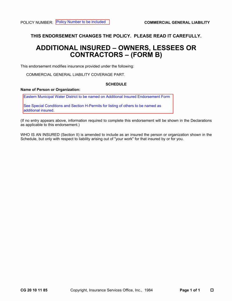
POLICY NUMBER: COMMERCIAL GENERAL LIABILITY
THIS ENDORSEMENT CHANGES THE POLICY. PLEASE READ IT CAREFULLY.
CG 20 10 11 85 Copyright, Insurance Services Office, Inc., 1984 Page 1 of 1 ��
ADDITIONAL INSURED – OWNERS, LESSEES ORCONTRACTORS – (FORM B)
This endorsement modifies insurance provided under the following:
COMMERCIAL GENERAL LIABILITY COVERAGE PART.
SCHEDULEName of Person or Organization:
(If no entry appears above, information required to complete this endorsement will be shown in the Declarationsas applicable to this endorsement.)
WHO IS AN INSURED (Section II) is amended to include as an insured the person or organization shown in theSchedule, but only with respect to liability arising out of "your work" for that insured by or for you.
Eastern Municipal Water District to be named on Additional Insured Endorsement Form
See Special Conditions and Section H-Permits for listing of others to be named asadditional insured.
Policy Number to be included
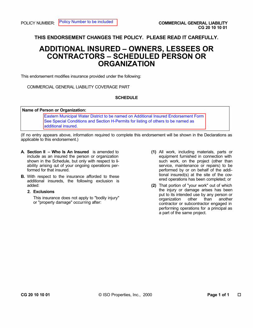
POLICY NUMBER: COMMERCIAL GENERAL LIABILITY CG 20 10 10 01
THIS ENDORSEMENT CHANGES THE POLICY. PLEASE READ IT CAREFULLY.
ADDITIONAL INSURED – OWNERS, LESSEES ORCONTRACTORS – SCHEDULED PERSON OR
ORGANIZATION This endorsement modifies insurance provided under the following:
COMMERCIAL GENERAL LIABILITY COVERAGE PART
SCHEDULE Name of Person or Organization:
(If no entry appears above, information required to complete this endorsement will be shown in the Declarations as applicable to this endorsement.) A. Section II – Who Is An Insured is amended to
include as an insured the person or organization shown in the Schedule, but only with respect to li-ability arising out of your ongoing operations per-formed for that insured.
B. With respect to the insurance afforded to these additional insureds, the following exclusion is added:2. Exclusions
This insurance does not apply to "bodily injury" or "property damage" occurring after:
(1) All work, including materials, parts or equipment furnished in connection with such work, on the project (other than service, maintenance or repairs) to be performed by or on behalf of the addi-tional insured(s) at the site of the cov-ered operations has been completed; or
(2) That portion of "your work" out of which the injury or damage arises has been put to its intended use by any person or organization other than another contractor or subcontractor engaged in performing operations for a principal as a part of the same project.
CG 20 10 10 01 © ISO Properties, Inc., 2000 Page 1 of 1 �
Policy Number to be included
Eastern Municipal Water District to be named on Additional Insured Endorsement FormSee Special Conditions and Section H-Permits for listing of others to be named asadditional insured.

POLICY NUMBER: COMMERCIAL GENERAL LIABILITY CG 20 37 10 01
THIS ENDORSEMENT CHANGES THE POLICY. PLEASE READ IT CAREFULLY.
ADDITIONAL INSURED – OWNERS, LESSEES ORCONTRACTORS – COMPLETED OPERATIONS
This endorsement modifies insurance provided under the following:
COMMERCIAL GENERAL LIABILITY COVERAGE PART
SCHEDULE Name of Person or Organization:
Location And Description of Completed Operations:
Additional Premium:
(If no entry appears above, information required to complete this endorsement will be shown in the Declarations as applicable to this endorsement.) Section II – Who Is An Insured is amended to include as an insured the person or organization shown in the Schedule, but only with respect to liability arising out of "your work" at the location designated and described in the schedule of this endorsement performed for that insured and included in the "products-completed operations haz-ard". CG 20 37 10 01 © ISO Properties, Inc., 2000 Page 1 of 1 �
Policy Number to be included
Eastern Municipal Water District to be named on Additional Insured Endorsement FormSee Special Conditions and Section H-Permits for listing of others to be named asadditional insured.
Project location and name to be listed here

Policy Number must be included
Project Name to be listed here


Policy Number to be included
Waiver of Subrogation form is always in favor of the Worker's Compensation.Endorsement to list EMWD and project.
Effective date must be specified
Name of Insured (per contract)
Signature
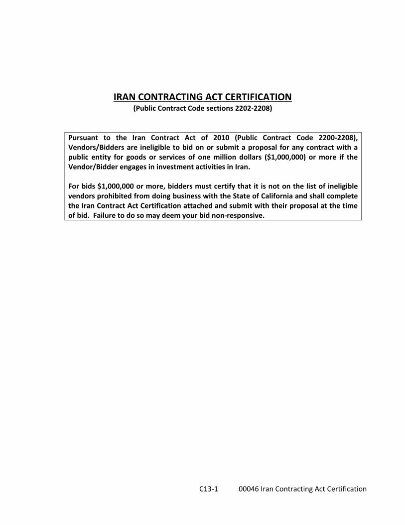
C13-1 00046 Iran Contracting Act Certification
IRAN CONTRACTING ACT CERTIFICATION (Public Contract Code sections 2202-2208)
Pursuant to the Iran Contract Act of 2010 (Public Contract Code 2200-2208), Vendors/Bidders are ineligible to bid on or submit a proposal for any contract with a public entity for goods or services of one million dollars ($1,000,000) or more if the Vendor/Bidder engages in investment activities in Iran. For bids $1,000,000 or more, bidders must certify that it is not on the list of ineligible vendors prohibited from doing business with the State of California and shall complete the Iran Contract Act Certification attached and submit with their proposal at the time of bid. Failure to do so may deem your bid non-responsive.

C13-2 00046 Iran Contracting Act Certification
[Page Left Intentionally Blank]
C13-3 00046 Iran Contracting Act Certification
IRAN CONTRACTING ACT CERTIFICATION Pursuant to the Iran Contract Act of 2010 (Public Contract Code 2200-2208), Vendors/Bidders are ineligible to bid on or submit a proposal for any contract with a public entity for goods or services of one million dollars ($1,000,000) or more if the Vendor/Bidder engages in investment activities in Iran.
MUST BE SUBMITTED WITH BID PROPOSAL IF BID AMOUNT IS $1,000,000 OR MORE
Prior to bidding on, submitting a proposal, or executing a contract or renewal for a public entity contract for goods or services of $1,000,000 or more, a vendor must either: a) certify it is not on the current list of persons engaged in investment activities in Iran created by the California Department of General Services (“DGS”) pursuant to Public Contract Code section 2203(b) and is not a financial institution extending $20,000,000 or more in credit to another person, for 45 days or more, if that other person will use the credit to provide goods or services in the energy sector in Iran and is identified on the current list of persons engaged in investment activities in Iran created by DGS; or b) demonstrate it has been exempted from the certification requirement for that solicitation or contract pursuant to Public Contract Code section 2203(c) or (d).
To comply with this requirement, please insert your vendor or financial institution name and Federal ID Number (if available) and complete one of the options below. Please note: California law establishes penalties for providing false certifications, including civil penalties equal to the greater of $250,000 or twice the amount of the contract for which the false certification was made, contract termination, and three-year ineligibility to bid on contracts. (Pub. Cont. Code § 2205.)
OPTION #1 - CERTIFICATION I, the official named below, certify I am duly authorized to execute this certification on behalf of the vendor/financial institution identified below, and the vendor/financial institution identified below is not on the current list of persons engaged in investment activities in Iran created by DGS and is not a financial institution extending twenty million dollars ($20,000,000) or more in credit to another person/vendor, for 45 days or more, if that other person/vendor will use the credit to provide goods or services in the energy sector in Iran and is identified on the current list of persons engaged in investment activities in Iran created by DGS.
I certify (or declare) under penalty of perjury under the laws of the State of California that the foregoing is true and correct. Vendor Name/Financial Institution (Printed)
Federal ID Number (or n/a)
By (Authorized Signature) Printed Name and Title of Person Signing
Date Executed

C13-4 00046 Iran Contracting Act Certification
OPTION #2 – EXEMPTION Pursuant to Public Contract Code sections 2203(c) and (d), a public entity may permit a vendor/financial institution engaged in investment activities in Iran, on a case-by-case basis, to be eligible for, or to bid on, submit a proposal for, or enters into or renews, a contract for goods and services. If you have obtained an exemption from the certification requirement under the Iran Contracting Act, please fill out the information below, and attach documentation demonstrating the exemption approval. Vendor Name/Financial Institution (Printed)
Federal ID Number (or n/a)
By (Authorized Signature) Printed Name and Title of Person Signing
Date Executed

C16-1 00050 CalOsha form 300A
Cal/OSHA Form 300A
Annual Summary of Work-Related Injuries and Illnesses
Bidders shall provide the most current, completed Cal/OSHA Form 300A with their bid (blank form attached)
Failure to submit this form “may” deem your bid non-responsive

00050 CalOsha form 300A
[PAGE LEFT INTENTIONALLY BLANK]

Cal
/OSH
A F
orm
300
A (R
ev. 7
/200
7)
App
endi
x B
A
nnua
l Sum
mar
y of
Wor
k R
elat
ed In
jurie
s an
d Ill
ness
es
D
epar
tmen
t of I
ndus
tria
l Rel
atio
ns
Div
isio
n of
Occ
upat
iona
l Saf
ety
& H
ealth
Year
20
__ _
_
C1
6-2
0005
0 Ca
lOsh
a fo
rm 3
00A
All
esta
blis
hmen
ts c
over
ed b
y C
CR
Titl
e 8
Sect
ion
1430
0 m
ust c
ompl
ete
this
Ann
ual S
umm
ary,
ev
en if
no
wor
k- re
late
d in
jurie
s or i
llnes
ses o
ccur
red
durin
g th
e ye
ar. R
emem
ber t
o re
view
the
Log
to v
erify
that
the
entri
es a
re c
ompl
ete
and
accu
rate
bef
ore
com
plet
ing
this
sum
mar
y.
Usi
ng t
he L
og,
coun
t th
e in
divi
dual
ent
ries
you
mad
e fo
r ea
ch c
ateg
ory.
The
n w
rite
the
tota
ls be
low
, mak
ing
sure
you
’ve
adde
d th
e en
tries
from
eve
ry p
age
of th
e Lo
g. If
you
had
no
case
s, w
rite
“0.”
Em
ploy
ees,
form
er e
mpl
oyee
s, an
d th
eir
repr
esen
tativ
es h
ave
the
right
to r
evie
w th
e C
al/ O
SHA
Fo
rm 3
00 i
n its
ent
irety
. Th
ey a
lso
have
lim
ited
acce
ss t
o th
e C
al/
OSH
A F
orm
301
or
its
equi
vale
nt.
See
CC
R T
itle
8 Se
ctio
n 14
300.
35,
in C
al/
OSH
A’s
rec
ordk
eepi
ng r
ule,
for
fur
ther
de
tails
on
the
acce
ss p
rovi
sion
s for
thes
e fo
rms.
Num
ber o
f Cas
es
To
tal n
umbe
r of
deat
hs
To
tal n
umbe
r of
case
s with
day
s aw
ay fr
om w
ork
To
tal n
umbe
r of
case
s with
job
trans
fer o
r res
trict
ion
To
tal n
umbe
r of
othe
r rec
orda
ble
case
s
(G
)
(H)
(I)
(J)
N
umbe
r of D
ays
Tota
l num
ber o
f day
s of
job
trans
fer o
r res
trict
ion
To
tal n
umbe
r of d
ays
away
from
wor
k
(K
)
(L)
In
jury
and
Illn
ess
Type
s To
tal n
umbe
r of…
(M
)
(1)
Inju
ries
(4)
Pois
onin
gs
(2)
Skin
diso
rder
s
(5
) H
earin
g lo
ss
(3)
Res
pira
tory
con
ditio
ns
(6)
All
othe
r Illn
esse
s
Post
this
Ann
ual S
umm
ary
from
Feb
ruar
y 1
to A
pril
30 o
f the
yea
r fol
low
ing
the
year
cov
ered
by
the
form
. Faci
lity
Info
rmat
ion
Esta
blis
hmen
t nam
e
St
reet
City
S
tate
Z
ip
In
dust
ry d
escr
iptio
n (e
.g. M
anuf
actu
rer o
f mot
or tr
uck
traile
rs)
St
anda
rd In
dust
rial C
lass
ifica
tion
(SIC
), if
know
n (e
.g. S
IC 3
715)
Empl
oym
ent I
nfor
mat
ion
(If
you
don
’t ha
ve th
ese
figur
es, u
se th
e op
tiona
l Wor
kshe
et to
esti
mat
e)
Ann
ual a
vera
ge n
umbe
r of e
mpl
oyee
s
____
_ To
tal h
ours
wor
ked
by a
ll em
ploy
ees l
ast y
ear
__
___
Sign
her
e K
now
ingl
y fa
lsify
ing
this
doc
umen
t may
res
ult i
n a
fine.
I c
ertif
y th
at I
have
exa
min
ed th
is do
cum
ent a
nd th
at to
the
best
of m
y kn
owle
dge
the
entri
es a
re tr
ue, a
ccur
ate,
and
com
plet
e.
Com
pany
exe
cutiv
e Ti
tle
Phon
e D
ate

0005
0 Ca
lOsh
a fo
rm 3
00A
[P
AGE
LEFT
INTE
NTI
ON
ALLY
BLA
NK]

C-17 Contractor’s Cal/OSHA Compliance History and SIC Code
THIS DOCUMENT IS TO BE SUBMITTED WITH THE PROPOSAL PACKAGE AT TIME OF BID
C17-1 00052 CalOsha Compliance History & SIC Code
Bidders shall complete and submit the attached C-17 form with the Proposal Package at time of bid
Failure to fully divulge, complete and submit this form “may” deem your bid
non-responsive

C17 00052 CalOsha Compliance History & SIC Code
[PAGE LEFT INTENTIONALLY BLANK]

C-17 Contractor’s Cal/OSHA Compliance History and SIC Code THIS DOCUMENT IS TO BE SUBMITTED WITH THE PROPOSAL PACKAGE AT TIME OF BID
C17-2 00052 CalOsha Compliance History & SIC Code
Bid Date: Contractor’s Standard Industry Code:
Specification No. Project Name:
Contractor name:
Contractor Address:
Contractor License No. Phone No:
Contact Person:
Please answer the following questions: 1. Has the Contractor been cited by Cal/OSHA or any regulatory agency for a violation related to
safety or environmental issues within the past seven (7) years? No Yes
If yes, please attach all documentation specific to each violation and what actions have been taken to ensure that there is not a repeat violation.
2. Has the Contractor had a fatality or serious incident per Cal/OSHA on a jobsite within the past ten (10) years? No Yes
If yes, please attach all documentation specific to each violation and what actions have been taken to ensure that there is not a repeat violation.
I certify (or declare) under penalty of perjury under the laws of the State of California that the foregoing is true and correct.
Contractor’s Representative signature:
Date:
Failure to fully divulge, complete and submit this form “may” deem your bid non-responsive
FOR EMWD USE ONLY: Field Engineering to forward to Risk Management for review
Approved: No Yes
Reviewed by Risk Management (signature required)
Date:
Return to (Field Eng.CAR) By:
cc: Construction Administrator File: C-17 Contractor’s Compliance History

C17 00052 CalOsha Compliance History & SIC Code
[PAGE LEFT INTENTIONALLY BLANK]

C19-1 00056 Safety Training Records
C-19 Employee Safety & Health Training Records
Documentation (spreadsheet) of safety and health training are required by Cal-Osha standards for each employee. The documentation must specifically include employee name or other identifier, training dates, type(s) of training and the name of the training provider. These records must be kept for at least one year, except that training records of employees who have worked for less than one year for the employer need not be retained beyond the term of employment if they are provided to the employee upon termination of employment.
General Contractor shall provide Employee Safety & Health Training Records for the past 12 months
(to be submitted on or after the Preconstruction Conference)

C19-2 00056 Safety Training Records
[PAGE LEFT INTENTIONALLY BLANK]

Rev: 6/3/19 C22-1 00057 Contractor Registration
PUBLIC WORKS CONTRACTOR REGISTRATION (Pursuant to SB 854)
This project is subject to compliance monitoring and enforcement by the Department of Industrial Relations. Pursuant to Section 1771.1 of the Labor Code, no contractor or subcontractor shall be qualified to bid on, be listed in a bid proposal pursuant to Section 4104 of the Public Contract Code, or engage in the performance of any contract for public work unless currently registered to perform public work pursuant to Section 1725.5 of the Labor Code. It shall not be a violation of this section for an unregistered contractor to submit a bid that is authorized by Section 7029.1 of the Business and Professions Code or by Sections 10164 or 20103.5 of the Public Contract Code, provided the contactor is registered to perform public work pursuant to Section 1725.5 at the time the contract is awarded.
BIDDERS AND THEIR SUBCONTRACTORS (listed on the Designation of Subcontractors List C-05) are to provide an extract (pdf or excel) at time of bid showing active registration from the Public Works Contractor Registration online registration at https://cadir.secure.force.com/ContractorSearch
******************************************************************************************************** SUBMIT BIDDER & SUBCONTRACTORS CONTRACTOR REGISTRATION
EXTRACTS WITH BID PROPOSAL (Either pdf or Excel Format) ********************************************************************************

Rev: 6/3/19 C22-2 00057 Contractor Registration
PAGE LEFT INTENTIONALLY BLANK

C23-1 Contractor’s Proof of Insurance Certificate
PROOF OF INSURANCE CERTIFICATE
The Contractor and his subcontractors shall take out and maintain insurance, with coverage acceptable to the District, at his sole cost and expense at all times during the life of the Contract, including the entire time of the Contractor's guarantee.
Note: An Aggregate limit (cap), Professional Employer Organization (PEO), or Self Insurance Plan is not acceptable.
Contractor to insert sample Insurance Certificate showing proof of acceptable Insurance

C23-2 Contractor’s Proof of Insurance Certificate
PAGE LEFT INTENTIONALLY BLANK
00062 General Conditions Section E - Inspection and Tests
E–1
Rev:08/31/15
GENERAL CONDITIONS
Section E - Inspection and Tests E-01. This section of the specifications supplements that paragraph of the General Conditions of this
specification entitled "Inspection and Testing of Materials".
A. Progress Reports. The Contractor shall furnish the District full information as to the progress of the work in its various parts and shall give the District timely notice of the Contractor's readiness for inspection. The District reserves the right to charge to the Contractor any additional cost of inspection and test when articles or materials are not ready at the time inspection is requested by the Contractor.
B. Inspection at Mill. Inspection will be made during manufacture of material. If the inspection or test, whether preliminary or final, is made on the premises of the Contractor, the Contractor shall furnish, without additional charge, all reasonable facilities and assistance for the safe and convenient inspection and test required by the Engineer.
C. Mill Test Reports. Whenever required by the Engineer the District shall be furnished promptly with complete certified copies of mill test reports showing chemical and physical properties of the materials to be furnished under the contract and also copies of rolling mill reports.
D. Samples or Test Specimens. Samples or test specimens of all materials, appliances, and fittings for delivery under these specifications or for incorporation in the products manufactured or fabricated hereunder shall be prepared at the Contractor's expense, except as otherwise specified herein, and shall be furnished to the Engineer, carriage prepaid, in such quantities and sizes as may be required by him for proper examination and in ample time for completion of all necessary tests or analyses before the time in which the Contractor desires to deliver or make use of same. Chemical tests and analyses, except those furnished by the Contractor under sub-paragraph (c) hereof, will be made by, or at the expense of, the District.
E. Inspection of Materials Not Locally Produced. When the Contractor intends to purchase materials, fabricated products, or equipment from sources located more than 100 miles outside the geographical limits of EMWD’s main office, the contractor will be responsible for the actual costs incurred for one inspector (EMWD staff or consultant employed by EMWD) to inspect the materials, equipment or process. The actual cost shall include $1,000/day for staff salary and the expenses incurred for airfare, vehicle rental, hotel, meals, etc.

00062 General Conditions Section E - Inspection and Tests E–2
This approval shall be obtained before producing any material or equipment. The inspector shall judge the materials by the requirements of the plans and specifications. The Contractor shall forward reports required by the Engineer. No materials or equipment shall be shipped nor shall any processing, fabrication or treatment of such materials be done without proper inspection. Approval shall not relieve the Contractor of responsibility for complying with the contract requirements.
END OF SECTION E

GENERAL CONDITIONS
Section F - Labor & Construction
C O N T E N T S
GENERAL CONDITIONS F-01. DEFINITIONS ........................................................................................................................ 1 F-02. CONTRACT DOCUMENTS ; GOVERNING LAW ; JURISDICTION ; VENUE ................................... 2 INSURANCE & BONDS ....................................................................................................................................... 3 F-03. CONTRACT SECURITY ........................................................................................................... 3 F-04. CONTRACTOR'S AND SUBCONTRACTOR'S INSURANCE .......................................................... 4 F-05. ADDITIONAL SURETY ............................................................................................................ 8 GENERAL REQUIREMENTS ................................................................................................................................ 8 F-06. AUTHORITY OF THE DISTRICT ............................................................................................... 8 F-07. PROTESTS ............................................................................................................................ 8 F-08. REPORTS, RECORDS AND DATA ............................................................................................ 9 F-09. TIME AND ORDER OF WORK ............................................................................................... 10 F-10. CONSTRUCTION SCHEDULE AND PERIODIC ESTIMATES ....................................................... 10 F-11. LEGAL ADDRESS OF CONTRACTOR ...................................................................................... 13 F-12. MUTUAL RESPONSIBILITY OF CONTRACTORS ...................................................................... 13 F-13. GENERAL GUARANTEE ....................................................................................................... 13 F-14. OBLIGATIONS OF CONTRACTOR.......................................................................................... 14 F-15. PERSONAL ATTENTION ....................................................................................................... 18 F-16. ASSIGNMENT OF RIGHTS. PURSUANT TO THE REQUIREMENTS OF CALIFORNIA GOVERNMENT
CODE SECTION 4552: .......................................................................................................... 18 F-17. SUBCONTRACTS ................................................................................................................. 19 F-18. PATENTS ............................................................................................................................ 20 F-19. PERMITS ............................................................................................................................ 21 F-20. ENVIRONMENTAL COMPLIANCE ......................................................................................... 21 F-21. ADDITIONAL RIGHTS-OF-WAY ............................................................................................ 21 F-22. PROTECTION AND PRESERVATION OF CULTURAL RESOURCES ............................................. 21 F-23. RIGHT OF THE DISTRICT TO TERMINATE CONTRACT ............................................................ 22 F-24. NOTICE AND SERVICE THEREOF .......................................................................................... 24 F-25. UTILITIES AND SUBSTRUCTURES ......................................................................................... 24 F-26. USE OF MATERIALS FOUND ON WORK SITE ......................................................................... 26 WORK ............................................................................................................................................................... 26 F-27. LINES, GRADES AND MEASUREMENTS ................................................................................ 26 F-28. PLANS AND SPECIFICATIONS .............................................................................................. 26 F-29. EQUIPMENT AND MATERIAL ITEMS .................................................................................... 27 F-30. CHANGES IN WORK AND EXTRAS ........................................................................................ 35 F-31. MATERIALS, WORKMANSHIP AND TESTS ............................................................................ 39 F-32. DELAYS .............................................................................................................................. 41 F-33. INSPECTION AND TESTING OF MATERIALS .......................................................................... 43 F-34. DEFECTIVE WORK OR MATERIAL ......................................................................................... 43 F-35. ACCESS TO WORK .............................................................................................................. 44 F-36. TIME FOR COMPLETION AND FOR DAMAGES FOR LATE COMPLETION ................................. 44 PAYMENT TO CONTRACTOR ........................................................................................................................... 45 F-37. QUANTITIES OF ESTIMATE .................................................................................................. 45 F-38. CLAIMS .............................................................................................................................. 45

F-39. ARBITRATION .................................................................................................................... 50 F-40. RETENTION ........................................................................................................................ 50 F-41. PAYMENT FOR EQUIPMENT ................................................................................................ 51 F-42. MEASUREMENT AND PAYMENT ......................................................................................... 51 F-43. DISTRICT'S RIGHT TO WITHHOLD CERTAIN AMOUNTS AND MAKE APPLICATION THEREOF ... 52 F-44. FINAL ESTIMATE AND PAYMENT ......................................................................................... 53 F-45. PAYROLLS OF CONTRACTORS AND SUBCONTRACTORS ........................................................ 53 F-46. PREVAILING RATES OF WAGES ........................................................................................... 54 F-47. COMPLETION AND ACCEPTANCE ........................................................................................ 55 F-48. FINAL PAYMENT DECLARATION .......................................................................................... 55 F-49. PAYMENT ONLY IN ACCORDANCE WITH CONTRACT ............................................................ 55 F-50. SUBSTANTIAL COMPLETION ............................................................................................... 55 F-51. MONIES MAY BE RETAINED ................................................................................................ 56 F-52. UNPAID CLAIMS ................................................................................................................. 56 F-53. EIGHT HOUR LAW .............................................................................................................. 56 F-54. OVERTIME - NO EXTRA COMPENSATION ............................................................................. 56 F-55. POSTING MINIMUM WAGE RATES ...................................................................................... 57 PERSONNEL ...................................................................................................................................................... 57 F-56. ACCIDENT PREVENTION - PUBLIC SAFETY ............................................................................ 57 F-57. CHARACTER OF WORKERS .................................................................................................. 57 F-58. EMPLOYMENT.................................................................................................................... 58 F-59. NONDISCRIMINATION IN EMPLOYMENT ............................................................................. 58 F-60. ENFORCEMENT OF ORDER .................................................................................................. 58 F-61. SAFETY, SANITARY AND MEDICAL REQUIREMENTS ............................................................. 58 F-62. SANITATION....................................................................................................................... 59 F-63. FIRST AID AND PROTECTIVE FACILITIES ............................................................................... 59 Exhibit A – Escrow Agreement for Security Deposits in Lieu of Retention

00064 General Conditions Section F - Labor & Construction
F-1
GENERAL CONDITIONS SECTION F - LABOR & CONSTRUCTION
GENERAL CONDITIONS F-01. DEFINITIONS
A. Wherever the words defined in this article, or pronouns used in their stead, occur in these specifications or in any of the other contract documents they shall have the meanings here given:
B. The word DISTRICT and OWNER shall mean the Eastern Municipal Water District
represented by the General Manager or his designee. All references to District and OWNER shall include Eastern Municipal Water District, the Board of Directors and each member of the Board, the officers and agents of the District, and the District’s consultants.
C. The words BOARD OF DIRECTORS or BOARD shall mean the Board of Directors of
the Eastern Municipal Water District.
D. The word AGENT or ENGINEER shall mean one who represents the District in dealings with third persons and acts on behalf and subject to the control of the District.
E. The word CONSULTANT shall mean a consulting firm rendering services to the
District under contract.
F. The word CONTRACTOR or PRIME CONTRACTOR shall mean a firm, duly licensed as a contractor by the State of California, entering into contract with the District for the performance of work required by these specifications, and the legal representatives of said firm, or the agent appointed to act for said firm in the performance of the work. Said firm is referred to throughout the contract documents as if of the singular number and masculine gender.
G. The word SUBCONTRACTOR shall mean a contractor who will perform work or labor
or render service to the prime contractor or a contractor licensed by the State of California who, under subcontract to the prime contractor, specially fabricates and installs a portion of the work or improvement according to detailed drawings contained in the plans and specifications.
H. The word INSPECTOR shall mean a person who observes the work assigned for
conformance with the approved design plans and specifications.

00064 General Conditions Section F - Labor & Construction F-2
I. The word CONSTRUCTION ADMINISTRATOR shall mean a person who administers construction project contracts, researches and plans for a variety of capital construction, and maintenance/improvement programs, and performs related duties.
J. The word WORK shall mean that which is proposed to be constructed or done
under the contract, including the furnishing of all labor, materials, equipment, and services.
K. Whenever in the specifications or upon the PLANS the words DIRECTED, REQUIRED,
PERMITTED, ORDERED, DESIGNATED, PRESCRIBED, or words of like import are used, it shall be understood that the direction, requirement, permission, order, designation, or prescription of the District is intended, and similarly the words APPROVED, ACCEPTABLE, SATISFACTORY, or words of like import shall mean approved or acceptable to, or satisfactory to the District, unless otherwise expressly stated.
L. EXTRA WORK shall mean additions in the work being performed when the District
determines, in writing, that it is not covered by contract unit prices or stipulated unit prices.
M. FORCE ACCOUNT shall mean work conducted by the District, as opposed to a third
party. Said work is performed by employees or other agents of the District.
N. The word PLAN(s) shall mean DRAWING(s) and STANDARD DETAIL(s).
O. The word SPECIFICATION(s) shall mean TECHNICAL SPECIFICATION(s), PRE-NEGOTIATED SCOPES OF WORK, SPECIAL PROVISIONS, DETAILED PROVISIONS and/or GENERAL CONDITIONS and related Contract Documents.
F-02. CONTRACT DOCUMENTS ; GOVERNING LAW ; JURISDICTION ; VENUE
A. Contract Documents. The Notice Inviting Bids, the Instructions to Bidders, the Proposal, the Notice-of-Acceptance-of-Proposal, Addenda, the Specifications, and the Plans, together with the Agreement, constitute THE CONTRACT, and what is called for in any one shall be as binding as if called for in all. The intention of the documents is to require a complete and finished piece of work including all labor, materials, equipment, and transportation necessary for the proper execution of the work. Anything shown in the plans and not in the specifications, or in the specifications and not in the plans, shall be performed by the Contractor as though shown in both the plans and the specifications.

00064 General Conditions Section F - Labor & Construction
F-3
B. Specification Precedence. In resolving conflicts resulting from errors or discrepancies in any of the Contract Documents, the order of precedence shall be as follows:
1. Special Conditions Revised by Addenda 2. Special Conditions 3. Permit Requirements 4. Addenda 5. Plans 6. Specifications 7. General Conditions
With reference to the drawings, the order of precedence shall be as follows:
1. Figures, such as coordinates or dimensions, govern over scaled dimensions 2. Detail drawings govern over general drawings 3. Addenda/Change Order drawings govern over Drawings 4. Drawings govern over standard drawings
C. Governing Law. The Contract, all Contract Documents, and all Work performed
hereunder shall be governed by and interpreted in accordance with the laws of the State of California, excluding any choice of law provisions. Notwithstanding any other provisions contained in any other documents, this paragraph shall take precedence over any such documents and may not be modified, altered, or changed in any manner whatsoever except by a written instrument duly executed by the District which refers specifically to this paragraph.
D. Jurisdiction; Venue. Any action taken to enforce this Contract shall be maintained
in the Superior Court of Riverside County, California. The parties expressly consent to the jurisdiction of said court and agree that said court shall be the proper venue for any such action. Notwithstanding any other provisions contained in any other documents, this paragraph shall take precedence over any such documents and may not be modified, altered, or changed in any manner whatsoever except by a written instrument duly executed by the District which refers specifically to this paragraph.
INSURANCE & BONDS F-03. CONTRACT SECURITY The Contractor shall furnish a performance bond in an amount at least equal to one hundred percent (100%) of the contract price as security for the faithful performance of this contract. A payment bond shall be furnished in an amount not less than one hundred percent (100%) of the contract price as security for the payment of all persons performing labor and/or furnishing materials or other supplies under this contract. All bonds shall be executed by admitted surety insurers, as defined in Code of Civil Procedure section 995.120.
00064 General Conditions Section F - Labor & Construction F-4 Pursuant to Section 995.660(a) of the Code of Civil Procedure, the Contractor shall submit the following documents with the performance and payment bonds:
A. The original, or a certified copy of the unrevoked appointment, power of attorney,
bylaws, or other instrument entitling or authorizing the person who executed the bond to do so;
B. A certified copy of the certificate of authority of the insurer issued by the State of
California’s Insurance Commissioner; and C. Copies of the insurer’s most recent annual and quarterly statements filed with the
Department of Insurance. The Contractor shall take out and maintain performance and payment bonds at his sole cost and expense at all times during the life of this contract, including the entire time of the Contractor's guarantee, with surety carriers admitted to transact business in the State of California.
The following provision shall be added to and made a part of the bond agreement:
"Surety agrees to the acceptance of arbitration as to any controversy or claim affecting its obligation where agreed to by the contracting parties pursuant to Arbitration of the Contract Conditions."
F-04. CONTRACTOR'S AND SUBCONTRACTOR'S INSURANCE The Contractor shall not commence work under this Contract until he has obtained and submitted all policies of insurance (including all endorsements) acceptable to the District, nor shall he allow any subcontractor to commence work until all policies of insurance of the subcontractor have been obtained (by the Contractor), as required hereunder.
The Contractor and his subcontractors shall take out and maintain insurance, with coverage acceptable to the District, at his sole cost and expense at all times during the life of this Contract, including the entire time of the Contractor's guarantee.
Each such policy of insurance shall:
A. Be issued by insurance carriers that are:
1. Rated no less than A-, Class VIII or better by the A. M. Best Company
2. Licensed to transact insurance business in the State of California
3. Captive and Risk Retention groups are not acceptable unless rated no less
than A-, VIII or better by the A. M. Best Company

00064 General Conditions Section F - Labor & Construction
F-5
4. Self Insured Retention (SIR) greater than $10,000 is not acceptable on any policy.
Any insurance carrier, which is strategically affiliated with a parent insurance company or insurance group, must disclose the name of the parent company or group in any certificate of insurance documentation provided to the District.
Non-admitted/Surplus Lines insurance carriers (carriers not licensed in the State of California) may be acceptable to the District under certain conditions. The District reserves the right to disqualify a non-admitted insurer without cause.
Non-admitted insurance carriers providing any form of insurance coverage must be:
1. Domiciled in the United States 2. Listed as an approved insurance carrier on the California Department of
Insurance L.E.S.L.I. list 3. Rated no less than “A-, Class VIII” or better by the A.M. Best Company 4. Captive and Risk Retention groups are not acceptable unless rated no less
than A, VIII or better by the A. M. Best Company
B. Name and list the District, Agent(s), and other personals and entities as required and specified in the special conditions, and/or all permittors listed in Section H – Permits, as additional insured, by utilizing “CG 2010 11/85" endorsement form or similar, to include completed-operations up to 5 years beyond the completion date. If CG 20 10 11/85 is not available, then additional insured endorsement CG 20 10 10/01 along with CG 20 37 10/01 (Additional Insured-Completed Operations) endorsements executed by the Insurance Company naming the District and others listed above shall be utilized.
C. The insurance contract should state that it is intended for the transferee’s policy to
apply on a primary basis, as would standard ISO form CG 00 01 10 01, on behalf of the additional insured and that it will be modified, if necessary, to provide coverage in this manner.
D. Require all deductibles be the sole responsibility of the Contractor, including the
deductible for any builders risk insurance policy procured by the District.
E. Not be canceled, reduced in coverage or limits until thirty (30) days after receipt by the District of a written notice of such cancellation including a ten (10) day notice for non-payment of premium, as evidenced by receipt of a registered letter
F. Otherwise be in form satisfactory to District.

00064 General Conditions Section F - Labor & Construction F-6
G. Any and all losses connected with the insurance policies in force for the District
shall require cooperation of the Contractor in determining the cause of loss, the repair process, and the securing of information to determine settlement of said claim. Failure to comply with the adjuster’s request or insurance carriers requests to settlement in a timely manner, will result in breach of contract.
The Contractor and his subcontractors shall take out and maintain the following policies of "occurrence form"-type insurance with coverage acceptable to the District:
H. Workers’ Compensation Insurance. In accordance with the provisions of Section
3700 of the Labor Code of the State of California, Contractor shall secure, at all times during the life of this contract, the payment of compensation to his employees; and the Contractor shall require all subcontractors similarly to provide such compensation insurance for all of the latter's employees. Such policy shall contain an endorsement which waives all right of subrogation against those persons and entities designated in the policy.
I. Commercial Liability Insurance. The Contractor shall procure and maintain at all
times during the life of this contract, Commercial Liability Insurance in amounts not less than the following amounts unless otherwise specified in the Special Conditions:
$2,000,000 per each occurrence $5,000,000 General Aggregate Limit $5,000,000 Products-Completed Operations Aggregate Limit $2,000,000 Personal & Advertising injury limit
THE POLICY IS TO BE ENDORSED FOR THE AGGREGATE LIMIT TO APPLY TO THIS PROJECT by utilizing endorsement form “CG 25 03 03 97” (or similar), executed by the insurance carrier. An aggregate limit (cap) is not allowed.
Where excess liability insurance is used in connection with primary liability insurance, the combination of such must allow total limits of liability to be in amounts not less than the above-specified amount.
J. Automobile Liability Insurance. The Contractor shall procure and maintain at all
times during the life of this contract, Automobile Liability insurance in amount not less than the following amount unless otherwise specified in the Special Conditions:
$2,000,000 combined single limit
K. Installation Floater. The Contractor shall maintain or cause to be maintained at all
times during the life of this contract, an Installation Floater in the amount of the total contract value.

00064 General Conditions Section F - Labor & Construction
F-7
The installation floater policy shall not contain a deductible higher than $1,000.00 per claim unless first approved by the District.
L. Contractors Equipment Floater (aka Commercial Inland Marine). The Contractor
shall maintain or cause to be maintained at all times during the life of this contract, an equipment floater to cover all tools, equipment, supplies and materials on the jobsite.
If specified in the Special Conditions, the Contractor shall provide the following coverage(s):
M. Builders Risk, Flood and Earthquake Insurance. The Contractor and his
subcontractors shall maintain or cause to be maintained at all times during the life of this contract, builders' risk "All Risk" completed value insurance, to include, at the option of the District, loss or damage caused by fire, earthquake and/or flood, insuring completed work, work in progress, material, supplies and equipment of the work site, in storage or in transit, in an amount equal to the full replacement cost thereof. Such insurance shall include the interests of the District, Contractor, all tiers of subcontractors, suppliers and materialmen, with deductible amounts, if any, for the sole account of and payable by Contractor. Loss under such insurance shall be adjusted with and payable to the District for the interest of all parties. The amount of property insurance shall be sufficient to protect against such loss or damage in full until the work is accepted by the District. EMWD must be named as “loss payee” on the certificate for Builder’s Risk policy.
Builder’s “All Risk” insurance policy, if obtained by the Contractor, shall contain a deductible not higher than $1,000 unless otherwise approved by the District.
Flood Insurance policy, if obtained by the Contractor, shall contain a deductible not higher than $100,000.00 unless otherwise approved by the District.
Earthquake insurance policy, if obtained by the Contractor, shall contain a deductible not higher than 10% of the total insurable value unless otherwise approved by the District.
Builder’s Risk, Flood and Earthquake Insurance by District. If specified in the Special Conditions, Builder’s “All Risk” Insurance may be provided by the District. The Contractor is responsible for any and all deductibles per Section F-04 subsection D. Financial considerations to determine viability of such deductible remains at the District’s discretion. Deductibles will be fully disclosed at the time of issuance of the Builder’s Risk contract.

00064 General Conditions Section F - Labor & Construction F-8
F-05. ADDITIONAL SURETY If during the continuance of the contract any of the sureties upon the faithful performance bond is no longer sufficient under Code of Civil Procedure section 995.660(b), District may require additional sureties which the Contractor shall furnish to the satisfaction of the District within fifteen (15) days after notice, and in default thereof the contract may be suspended and the work completed as provided in section titled Right of the District to Terminate Contract.
GENERAL REQUIREMENTS F-06. AUTHORITY OF THE DISTRICT The District shall give all orders, lines, grades, and directions contemplated under the contract; shall determine the adequacy of the Contractor's methods, plant, and appurtenances; shall determine in all cases the amount, quality, acceptability, and fitness of the several kinds of work and materials which are to be incorporated in the work; and shall decide in all cases every question which may arise relative to the fulfillment of this contract on the part of the Contractor.
Should any discrepancy appear or any misunderstanding arise as to the import of anything contained in the specifications or plans, the matter shall be referred to the District, which shall decide the same in accordance with the true intent and meaning as construed by the District, and the District’s decision shall be binding on the Contractor. Any difference or conflict which may arise between the Contractor and any other contractors of the District in regard to their work shall be adjusted and determined by the District. The District’s estimates and decisions shall be final and conclusive, except as herein otherwise expressly provided.
F-07. PROTESTS If the Contractor considers any work demanded of him to be outside the requirements of the contract, or if he considers any record or ruling of the District to be unfair, he shall immediately upon such work being demanded or such record or ruling being made, ask for written instructions or decisions, upon the receipt of which he shall proceed without delay to perform the work or conform to the record or ruling. In the event the Contractor finds such instructions or decisions unsatisfactory, he shall, within ten (10) days after receipt of same, file a written protest with the District, stating clearly and in detail his objections and the reasons therefore. Except for such grounds of protest or objections as made of record in the manner specified and within the time stated herein, the Contractor hereby waives all grounds of protest or objections to the records, rulings, instructions, or decisions of the District, and hereby agrees that as to all matters not included in such protests the records, instructions, and decisions of the District shall be final and conclusive.

00064 General Conditions Section F - Labor & Construction
F-9 F-08. REPORTS, RECORDS AND DATA
A. General. The Contractor shall submit to the District such of his schedules and schedules of each of his subcontractors as the District may request concerning work performed or to be performed under this contract, including schedules of quantities and costs, progress schedules, payrolls, reports, estimates, records, and other data.
Before proceeding with construction, the Contractor shall furnish the District with information, plans and prints for all structures, articles, machinery or fabricated materials to be entered into permanent construction which are by these specifications and/or plans to be furnished by the Contractor and of which detailed plans are not furnished by the District. Such information, plans and prints shall be submitted to the District for approval and shall become the property of the District.
B. Asbuilt Project Record Documents. The Contractor shall maintain, at the job site,
one complete set of Contract Specifications, Addenda, Change Orders and other directions, approved submittals, including one set of full size plans marked to show any deviations which have been made from the plans or approved shop drawings, including buried or concealed construction and utility features which are revealed during the course of construction. Special attention shall be given to recording the horizontal and vertical location of all buried utilities that differ from the locations indicated or which were not indicated on the plans. Said record drawings shall be supplemented by any detailed sketches as necessary or directed, to indicate fully the work as actually constructed.
Current Asbuilt record drawings shall be accessible to the District at all times during the construction period. They shall be reviewed with the District at regular intervals.
Asbuilt Record Plans and Specifications shall be clearly and correctly annotated by the Contractor to show all changes made during the construction process at the time the changed Work is installed.
Upon completion and prior to final inspection of the Work, the Contractor shall submit the Record Plans and Specifications to the District for review, and shall make such revisions or corrections as may be necessary for them to be a true, complete, and accurate record of the Work in the opinion of the District. When approved, the Contractor shall deliver the Asbuilt Record Drawings and Specifications to the District. If requested by the District, transparencies shall be furnished for record drawings of piping, electrical, and instrumentation information.

00064 General Conditions Section F - Labor & Construction F-10
F-09. TIME AND ORDER OF WORK
Immediately upon receipt of Notice of Acceptance of his Proposal, the Contractor shall schedule material orders for all material required under the contract, and notify the District of the anticipated dates of the availability of that material.
The contract time and construction period shall be as indicated in the Notice Inviting Bids except as otherwise superseded by Addendum or Change Order, or as otherwise defined in the Special Conditions.
No extension of time shall be made for ordinary delays and accidents and the occurrence of such shall not relieve the Contractor from the necessity of maintaining the required progress. In case of an extension by the District of the time for the completion of the contract, as hereinafter provided, a revised Construction Progress Schedule and/or Project Control Schedule may be required in accordance with such extension of time.
The time in which the various portions and the whole of the contract are to be performed, and the work is to be completed, is of the essence of this contract.
F-10. CONSTRUCTION SCHEDULE AND PERIODIC ESTIMATES
A. Required Forms. The Contractor shall deliver to the District at the Pre-Construction Conference or within such additional time as may be allowed by the District, the following: (Additional forms may be required as called out in Standard form EN-48)
Forms supplied by the District
1. Insurance Certificate(s);
2. Schedule of Values: Breakdown of the Contract Price showing sizes and
quantities of equipment items;
3. EN-61: Satisfactory evidence of placement of orders for all materials;
4. EN-57: Shoring Plan, including Cal OSHA form 421-2 Activity Notification;
5. Contractor’s Financial Qualification form;
6. Authorized Signatures;
7. C-11: Workers’ Compensation Certificate;
8. EN-183: Verification of pre-approved materials list;
9. EN-84: Specific Operating Safety Procedure - Exhibit “B” of Section 01000- General Safety Requirements;

00064 General Conditions Section F - Labor & Construction
F-11 10. EN-2: 24-hour emergency telephone numbers;
11. EN-146: Certified Payroll Form;
12. Prevailing Wage Rate;
13. C-13: Certificate by Single Instrument Supplier (if applicable)
14. Employee Safety & Health Training Records
15. Subcontractors List/Worker Classification of all subcontractors, including tiered subcontractors, performing work on the project.
16. Contractor’s Financial Qualification Form
17. Maintenance Bond for Pumping Equipment (if applicable)
Contractor's Forms
1. Project Control Schedule
2. DOSH Permit; (Dept. of Occupational Safety & Health)
3. Injury & Illness Prevention Program;
4. Other documentation, as required
The Schedule of Values (refer to Section 01026) shall be the basis for payment of contract work and will be used to establish payment for any “extra work” i.e., work requested which is beyond the scope of the original contract. The Contractor shall, prior to mobilizing or commencing any contract work, submit and receive District approval of Proof of Insurance, Injury and Illness Prevention Program, and EN-84, Specific Operating Safety Procedure. The Contractor shall be responsible to submit and receive District approval of the Schedule of Values (see Section 01026, if applicable) by the 10th of the month for processing of the monthly progress payment. Submittal and approval of the Schedule of Values beyond the 10th of the month will result in the progress payment to be processed the following month. The Contractor shall revise and update the Project Control Schedule as scheduling changes occur, and shall supply the District and his subcontractors with copies of the Project Control Schedule and its updates. District acceptance of revised Project Control Schedules shall be subject to the conditions of paragraph below.

00064 General Conditions Section F - Labor & Construction F-12
B. Contractor’s Project Control Schedule. The Contractor’s Project Schedule shall consist of a simple Critical Path Method analysis in chart form reflecting workable logic, and showing proper duration, expected methods, and mile posts, and shall conform to the work and time set forth in the contract. It shall clearly indicate all construction activities, sub-activities, and mile posts on a time-oriented basis, with the critical path fully identified. The following minimum information shall be included for each activity and critical path item:
1. Date of initial submittal, as applicable. 2. Ordering dates for long lead-time items. 3. Dates for materials on the site. 4. Start-work dates. 5. Complete-work dates. 6. Testing and clean-up dates. 7. Final contract completion date.
The schedule shall show a maximum of three critical paths, with only enough points or items to present the above information. Partial schedules will not be accepted without the approval of the District. The Contractor shall submit each schedule, using Primavera P6 (or later version) or Suretrak Project Manager.
Treatment plant, lift station and pump station charts shall be updated and resubmitted monthly; pipeline and other projects shall be updated and resubmitted monthly or as necessary to reflect changes in scheduling. All slippages and missed mile posts shall be flagged, with a narrative attached describing proposed corrective actions.
Payment Withheld. Payments due the Contractor shall be withheld until the Project Control Schedule is submitted by the Contractor and accepted by the District. Acceptance by the District of the baseline schedule submission shall be recognition of the Contractor’s good faith submission, and is solely for the purpose of releasing these monies. The District shall not unreasonably withhold its’ acceptance, however, acceptance shall not constitute approval. The District shall accept the Project Control Schedule only after all corrections and other issues have been fully resolved.
The applicable monies listed in the following table shall be withheld from that owed the Contractor each and every month an updated progress control schedule submission is not timely received in a condition acceptable to the District and conforming to the contract documents.

00064 General Conditions Section F - Labor & Construction
F-13
CONTRACT VALUE AMOUNT WITHHELD PER MONTH
$0 to $50,000 $1,000
$50,000 to $100,000 $1,500
$100,000 to $500,000 $2,500
$500,000 to $1,000,000 $5,000
$1,000,000 to $5,000,000 $7,500
$5,000,000 to $10,000,000 $10,000 F-11. LEGAL ADDRESS OF CONTRACTOR The address given in the Contractor's proposal on which the contract is founded is hereby designated as the place to which all notices, letters, and other communications to the Contractor shall be mailed or delivered. Nothing herein contained shall be deemed to preclude or render inoperative the service of any notice, letter, or other communication upon the Contractor personally. F-12. MUTUAL RESPONSIBILITY OF CONTRACTORS If, through acts of neglect on the part of the Contractor, any other contractor or any subcontractor shall suffer loss or damage on the work, the Contractor agrees to settle with such other contractor or subcontractor by agreement or arbitration if such other contractor or subcontractor will so settle. If such other contractor or subcontractor shall assert any claim against the District on account of any damage alleged to have been sustained, the District shall notify the Contractor, who shall indemnify and save harmless the District against any such claim, and he shall assume the defense of, and indemnify and save harmless the District from all liability and claims of any kind. F-13. GENERAL GUARANTEE
A. Acceptance and Repair. Neither the final certificate of payment nor and provision in the contract documents nor partial or entire occupancy by the District shall constitute an acceptance of work not done in strict compliance with the contract documents or relieve the Contractor of liability in respect to any express warranties or responsibility for faulty materials or workmanship. The Contractor shall remedy any defects in the work and pay for any damage to other work resulting therefrom.
00064 General Conditions Section F - Labor & Construction F-14
The Contractor's warranty and guarantee shall include the entire Work and all parts thereof, including that performed and constructed by Subcontractors, Sub-subcontractors, and others employed directly or indirectly on and for the Work, against faulty or defective materials, equipment, or workmanship for a period of one (1) year from the date of the District's written final acceptance of the Work or such longer period of time as may be prescribed by the terms of any special guarantee or warranty required by the Contract Documents, or by law. The only exception to this guarantee shall be the equipment, which shall be guaranteed for one (1) year from the date each item of equipment, itself, is placed in service. The District will give notice of observed defects with reasonable promptness.
F-14. OBLIGATIONS OF CONTRACTOR
A. Percentage of Work by Contractor. The Contractor shall perform, with his own organization, contract work amounting to at least 50 percent of the contract. When an entire item is subcontracted, the value of work subcontracted will be based on the contract unit price. When a portion of an item is subcontracted, the value of work subcontracted will be based on the estimated percentage of the contract unit price. This will be determined from information submitted by the Contractor and subject to approval by the District.
B. General. The Contractor at his sole cost and expense shall perform all labor and
services and furnish all the materials, tools and appliances, except as hereinafter otherwise specifically provided, necessary or proper for performing and completing the work required by these specifications, in the manner and within the time stipulated in the Special Conditions and Detailed Provisions. He shall furnish, erect, maintain, and remove the construction plant and such temporary works as may be required. If at any time before the commencement or during the progress of the work or any part of it, the Contractor's methods or appliances appear to the District to be unsafe, or inadequate for securing the safety of the workers, or the quality of work required, the District may notify the Contractor to correct any deficiencies. The Contractor shall respond to such notifications at his own expense, but the making of such notifications shall not relieve the Contractor of his obligations to secure the safe conduct of the work, the quality of work required and the rate of progress stipulated in the contract.
The Contractor alone shall be responsible for the safety, efficiency, and adequacy of his plant, appliances, and methods, and for any damage, which may result from their failure or their improper construction, maintenance, or operation. All the labor, services, and materials shall be performed and furnished strictly pursuant to, and in conformity with the contract documents. The Contractor shall complete the entire work to the satisfaction of the District, and in accordance with the contract documents herein mentioned and with approved changes in the work.

00064 General Conditions Section F - Labor & Construction
F-15
1. Contractor’s Responsibility for the Work and Materials. Until the acceptance of the contract, the Contractor shall have the charge and care of the work and of the materials to be used therein (including materials for which the Contractor has received partial payment or materials which have been furnished by the District) and shall bear the risk of injury, loss or damage to any part thereof by the action of the elements or from any other cause, whether arising from the execution or from the non-execution of the work. The Contractor shall rebuild, repair, restore, and make good all injuries; losses or damages to any portion of the work or the materials occasioned by any cause before its completion and acceptance and shall bear the expense thereof. Where necessary to protect the work or materials from damage, the Contractor shall, at the Contractor’s expense, provide suitable drainage of the roadway and erect those temporary structures that are necessary to protect the work or materials from damage. The suspension of the work from any cause whatever shall not relieve the Contractor of the responsibility for the work and materials as herein specified.
If ordered by the Engineer, the Contractor shall, at the Contractor’s expense, properly store materials, which have been partially paid for by the District or which have been furnished by the District. Storage by the Contractor shall be on behalf of the District and the District shall at all times be entitled to the possession of the materials, and the Contractor shall promptly return the materials to the site of the work when requested. The Contractor shall not dispose of any of the materials so stored except on written authorization from the Engineer.
2. Disposal of Excavated Materials. All materials removed from the excavations
in excess of that stored temporarily as above specified shall be immediately hauled away and used in backfilling elsewhere, or, if not used, shall be disposed of by the Contractor. The disposal area shall be acquired by the Contractor. No materials shall be disposed of either temporarily or permanently on privately or publicly owned property unless the Contractor shall first obtain permission therefore from the owner or agency concerned. The Contractor shall be responsible for all damages and claims that may arise in connection therewith. The Contractor shall provide a release form obtained from the property owner(s) releasing the District from any liability. Said written release shall be submitted and approved by the District prior to Contractor moving materials onto said property.
C. Temporary Facilities. The Contractor shall provide all temporary facilities and
utilities required for prosecution of the work, protection of employees and the public, protection of the work from damage by fire, weather or vandalism and such other facilities as may be specified or required by any legally applicable law, ordinance, rule or regulation.

00064 General Conditions Section F - Labor & Construction F-16
1. Electricity. The Contractor shall arrange with the local utility to provide adequate temporary electrical service at a mutually agreeable location. The Contractor shall then provide adequate job site distribution facilities conforming to applicable codes and safety regulations. The Contractor shall provide at his own cost all electric power required for construction, testing, general and security lighting, and all other purposes whether supplied through temporary or permanent facilities, until the substantial completion of the project.
2. Lighting. The Contractor shall provide temporary lighting in all work areas
sufficient to maintain a lighting level during working hour’s not less than lighting level required by California OSHA standards. As permanent lighting facilities are completed they may be used in lieu of temporary facilities, provided however, that any facilities so used shall be re-lamped prior to substantial completion. The temporary lighting surrounding the facility shall be designed, arranged and installed so as to confine direct rays onto the premises.
D. Equipment Testing. All items of mechanical equipment, including equipment
furnished by the District, shall be tested by the Contractor after installation for proper operation, efficiency and capacity. The Contractor shall furnish all personnel, power, water, chemicals, fuel, oil, grease, and all other necessary facilities for conducting the Contractor's test operations.
E. Preconstruction Safety Meeting. Safety of all activities in connection with the work
is of paramount and overriding importance to the District. A safety conference shall be scheduled prior to the preconstruction conference to review the respective safety requirements and to discuss implementation of all health and safety provisions to the project.
F. Preconstruction Conference and Progress Meetings. The District shall arrange for
a preconstruction conference to be attended by the Contractor's Superintendent and representatives of utilities, permit agencies, major subcontractors, and others whose input may be desired.
The purpose of this conference shall be to establish a working understanding between the parties and to discuss the construction schedule, shop drawing submittals and approvals, cost breakdown of major lump sum items, applications for payment and their processing, and such other subjects and submittals as may be pertinent to the project.
The District shall arrange and conduct periodic progress meetings as required. These meetings shall be attended by the Contractor's Superintendent, the District, and representatives of all subcontractors, utilities, etc., that are active on the project site. The purpose of these meetings shall be to resolve conflicts, ensure that the Contractor is monitoring the work progress, and coordinating and expediting the operation of all organizations active at the project site.

00064 General Conditions Section F - Labor & Construction
F-17
G. Project Site Maintenance. Daily throughout all phases of construction until final acceptance of project work, the contractor shall keep the work-site clean and free of graffiti, rubbish, and debris. The Contractor shall abate dust nuisance by spraying water, sweeping, or other means as necessary to the satisfaction of the District.
H. Defense and Indemnity. Contractor will defend, indemnify, and hold and save
District harmless from any and all actions, claims, damages to persons or property, penalties, obligations, or liabilities that may be asserted or claimed by any person, firm, entity, corporation, political subdivision or other organization arising out of or in connection with the work, operation, or activities of Contractor, its agents, employees, subcontractors, or invitees provided for herein, whether or not caused in part by any act or omission
(passive or comparative negligence included) of the District, excepting the active negligence of the District.
1. Contractor will defend any action or actions filed in connection with any
of said claims, damages, penalties, obligations or liabilities and will pay all costs and expenses, including attorneys' fees incurred in connection therewith.
2. Contractor will promptly pay any judgment rendered against
Contractor or District covering such claims, damages, penalties, obligations and liabilities arising out of or in connection with such work, operations, or activities of Contractor hereunder and Contractor agrees to save and hold District harmless therefrom.
3. In the event District, without the fault of District, is made a party to any
action or proceeding filed or prosecuted against Contractor for damages or other claims arising out of or in connection with the work, operation or activities of Contractor hereunder, Contractor agrees to pay to District any and all costs and expenses incurred by District in such action or proceeding together with the reasonable attorneys' fees. So much of the money due to the Contractor under and by virtue of the Contract as shall be considered necessary by the District may be retained by the District until disposition has been made of such actions or claims for damages as aforesaid. The Contractor shall not be responsible for actions, claims, damages to persons or property, penalties, obligations or liabilities arising from the sole negligence or willful misconduct of District.

00064 General Conditions Section F - Labor & Construction F-18 F-15. PERSONAL ATTENTION The Contractor shall give his personal attention constantly to the faithful prosecution of the work, and shall be present continually, either in person or by a duly authorized and competent representative, on the site of the work, during its progress, to give directions or receive instructions from the District Inspector. This duly authorized representative shall not be replaced without ten days written notice to the District except under extraordinary circumstances. The Contractor's representative at the site shall have the authority to act on behalf of the Contractor. All communications, instructions, and directions given to the representative shall be as binding as if given to the Contractor. Whenever the Contractor or the representative is not present on a part of the Work where the District wishes to give orders or directions, the orders or directions shall be received and obeyed by the foreman in charge of that part of the Work the same as if the order or direction had been given to the Contractor or to his representative. Any order or direction given by the District not otherwise required to be in writing will be given or confirmed in writing upon request of the Contractor. F-16. ASSIGNMENT OF RIGHTS. PURSUANT TO THE REQUIREMENTS OF CALIFORNIA GOVERNMENT CODE SECTION 4552: In submitting a bid to the District, the Contractor offers and agrees that if the bid is accepted, he will assign to the District all rights, title, and interest in and to all causes of action he may have under Section 4 of the Clayton Act (15 U.S.C. Sec. 15) or under the Cartwright Act (Chapter 2 (commencing with Section 16700) of Part 2 of Division 7 of the Business and Professions Code), arising from purchases of goods, services, or materials pursuant to the bid. Such assignment shall be made and become effective at the time the District tenders final payment to the Contractor. The Contractor shall not assign, transfer, convey, sublet, or otherwise dispose of this contract, or of his right, title or interest in or to the same or any part thereof, to other than the District without previous consent in writing. He shall not assign, by power of attorney or otherwise, any of the monies to become due and payable under the contract, unless by and with the like consent signified in like manner. If the Contractor shall without some previous written consent, assign, transfer, convey, sublet, or otherwise dispose of the contract, or of his right, title or interest therein, or of any of the monies to become due under the contract, to any other person, company, or other corporation, the contract may at the option of the District, be terminated, revoked and annulled. In such case, the District shall thereupon be relieved and discharged from any and all liability and obligations growing out of the contract, and no right to any money to become due hereunder, shall be asserted against the District in law or equity by reason of any so-called assignment of any monies to become due hereunder, unless authorized as aforesaid by the written consent of the District. In case the Contractor assigns all or any part of any monies due or to become due under this contract, the instrument of assignment shall contain a clause substantially to the effect that it is agreed that the right of the assignee in and to any monies due or to become due to the Contractor shall be subject to prior claims of all persons, firms and corporations for services rendered or materials supplied for the performance of the work called for in this contract.

00064 General Conditions Section F - Labor & Construction
F-19 F-17. SUBCONTRACTS
A. Extent. At the discretion of the District, and subject to the provisions of subsection c. hereof, subcontracts may be permitted to such extent, and only to such extent, as shall be shown to be necessary or definitely advantageous to the principal contractor in the prosecution of the work, and without injury to the interests of the District. The re-subletting of work by a subcontractor shall be subject to the same limitations as an original subletting. In general, the brokering of work will not be favored, and the subletting of the entire contract, or of substantial complete units of it, will be permitted only upon adequate showing of necessity, involving some new condition not reasonably foreseeable at the time of proposal. No subcontract will be permitted which has the effect of avoiding the residence or wage requirements or any other provisions of the main contract. Individual subcontractors, or members of contracting or subcontracting organizations, personally engaged upon the work, shall be subject to all the requirements of the paragraphs of the General Provisions of this specification, and to all other conditions of these specifications applicable to employees working for wages.
B. Subcontractors Listing; Subletting and Subcontracting Fair Practices Act.
Reference is hereby made to the provisions of Public Contract 4100, et. seq. As required by these provisions, each bidder shall set forth in his proposal the name, the location of the place of business, and the California contractor license number of each subcontractor who will perform work or labor or render service to the general contractor in or about the construction of the work or improvement in an amount in excess of one-half of one per cent (1/2 of 1%) of the general contractor's total bid, as well as the portion of the work which will be done by each subcontractor. Each subcontractor shall possess, both at the time the bid is submitted and at all times when work is performed, a valid contractor's license for the appropriate classification necessary to perform the work for which that subcontractor is listed. Each subcontractor shall be registered with the Department of Industrial Relations at time of bid and during the performance of the Contract. Any information requested by the District concerning any subcontractor who the prime contractor is required to list, other than the subcontractor’s name and location of business, may be submitted by the general contractor up to 24 hours after the deadline established by the District for receipt of bids.

00064 General Conditions Section F - Labor & Construction F-20
C. Contract Provisions. Before the work of any subcontractor is started, the Contractor shall submit, at the preconstruction conference, a Subcontractors List and Worker Classification form giving the name, business, license number, email address, and worker classification for each subcontractor who will perform work on the project. Contractor shall update and resubmit the Subcontractors List and Worker Classification as required.
Each subcontract shall provide for its annulment by the Contractor at the order of the District if in the District’s opinion the subcontractor fails to comply with the requirements of the principal contract insofar as the same may be applicable to his work. Nothing herein contained shall create any contractual relation between any subcontractor and the District, or relieve the Contractor of any liability or obligation hereunder. The Contractor shall cause appropriate provisions to be inserted in all subcontracts relative to the work to bind subcontractors to the Contractor by the terms of the Specifications and other Contract Documents insofar as applicable to the work of subcontractors and to give the Contractor the same power as regards to terminating any subcontract that the District may exercise over the Contractor under any provisions of the Contract Documents. The Contractor shall be as fully responsible to the District for the acts and omissions of his subcontractors, and of persons either directly or indirectly employed by them, as he is for the acts and omissions of persons directly employed by him.
F-18. PATENTS
The Contractor shall hold and save harmless the District from liability of any nature or kinds, including costs and expenses, for, or on account of any patented or unpatented invention, process, article, or appliance manufactured or used in the performance of the contract, including its use by the District, unless otherwise specifically stipulated in the Contract Documents. If the Contractor uses any design, device or materials covered by letters, patent or copyright, he shall provide for such use by suitable agreement with the Owner of such patented or copyrighted design, device or material. It is mutually agreed and understood that, without exception, the contract prices shall include all royalties or costs arising from the use of such design, device or materials, in any way involved in the work. The Contractor and/or his sureties shall indemnify and save harmless the District from any and all claims for infringement by reason of the use of such patented or copyrighted design, device or materials or any trademark or copyright in connection with work agreed to be performed under this contract, and shall indemnify the District for any cost, expense or damage which it may be obliged to pay by reason of such infringement at any time during the prosecution of the work or after completion of the work.

00064 General Conditions Section F - Labor & Construction
F-21
F-19. PERMITS
All required permits, easements, land and rights-of-way necessary for the work under this specification will be acquired by the District insofar as the District may acquire these permits.
All provisions of any permit included as a part of these specifications by incorporation in the Contract Documents shall be assumed by the Contractor as if written in these specifications. In the event the Contractor, subsequent to issuance of such permit, to perform work in a manner approved by the District but different than anticipated by the permit, he shall assume any and all costs or permit fees that result from that departure from the permit provisions. (For example, if the Contractor elects to slope his trench walls when the encroachment permit has been issued for a vertical wall trench, the permit fee for pavement replacement could increase.) In the event a performance bond is required by the provisions of a permit, a Dual Obligee Rider to the District Performance Bond, naming also the Permitting Agency, will be acceptable to the District.
F-20. ENVIRONMENTAL COMPLIANCE The contractor shall comply with all requirements of applicable Federal, State and local environmental rules and regulations. Any infractions of said rules and regulations by the Contractor during the term of the contract, which result in penalties, will be the responsibility of the Contractor. The District operates under a number of environmental permits issued by various agencies. If due to an action, inaction or negligence by the Contractor the District becomes subject to non- compliance penalties, the cost of such penalties shall be borne by the Contractor. F-21. ADDITIONAL RIGHTS-OF-WAY Should the Contractor find it advantageous to use any land in addition to that provided by the District for his construction yard or for other purposes during the construction of the work, he shall provide the use of such lands at his own expense and shall be solely responsible for acquisition of the appropriate title or other interest for said land. F-22. PROTECTION AND PRESERVATION OF CULTURAL RESOURCES In accordance with the National Historic Preservation Act of 1966, as amended through 2000 (16 U.S.C. 470) and PPM 75-27, the following procedures are implemented to insure historic preservation and fair compensation to the Contractor for delays attendant to cultural resources investigations. In the event potential historical, architectural, archaeological, or cultural resources (hereinafter cultural resources) are discovered during subsurface excavation at the site of construction, the following procedures shall be instituted:
00064 General Conditions Section F - Labor & Construction F-22
A. The District shall issue a "Stop Work Order" directing the Contractor to cease all construction operations at the location of such potential cultural resources find.
B. Such "Stop Work Order" shall be effective until such time as a qualified
archaeologist designated by the District has been able to assess the value of these potential cultural resources and make recommendations. Any "Stop Work Order" shall contain the following: 1. A clear description of the work to be suspended;
2. Any instructions regarding issuance of further orders by the Contractor
for material services;
3. Guidance as to action to be taken on subcontracts;
4. Any suggestions to the Contractor as to minimization of this cost;
5. Estimated duration of the temporary suspension.
If the archaeologist determines that the potential find is a bona fide cultural resource, the District shall extend the duration of the "Stop Work Order" in writing, and the Contractor shall suspend work at all locations of the find. Equitable adjustments of the construction contract shall be made in the following manner:
A. Time Extension. If the work temporarily suspended is on the "critical path", the total number of days for which the suspension is in effect shall be added to the number of allowable contract days.
B. Additional Compensation. If, as a result of a suspension of the work, the
Contractor sustains a loss which could not have been avoided by his judicious handling of forces, equipment, or redirection of forces or equipment to perform other work on the contract, the District shall provide for a fair and reasonable compensation for the Contractor's actual loss in accordance with Section pertaining to Changes in Work and Extras.
F-23. RIGHT OF THE DISTRICT TO TERMINATE CONTRACT
A. Contract Termination for Breach/Default. In the event that any of the provisions of this contract are violated by the Contractor or by any of his subcontractors, the District may serve written notice upon the Contractor and the Surety of its intention to terminate the contract.

00064 General Conditions Section F - Labor & Construction
F-23 Such notice to contain the reasons for such intention to terminate the contract, and unless within ten (10) days after the serving of such notice upon the Contractor, such violation or delay shall cease and satisfactory arrangement of correction is made, the contract shall, upon the expiration of said ten (10) days, cease and terminate.
In the event of any such termination, the District shall immediately serve notice
thereof upon the Surety and the Contractor, and the Surety shall have the right to take over and perform the contract.
If the Surety does not commence performance thereof within five (5) days from the date of mailing to such Surety of notice of termination, the District may take over the work and prosecute the same to completion by contract or by force account for the account and at the expense of the Contractor. The Contractor and his surety shall be liable to the District for any excess cost occasioned the District thereby, and in such event the District may take possession of and utilize in completing the work, such materials, appliances, and plant as may be on the site of the work and necessary therefore.
B. Contract Termination Based on the Best Interests of the District. The District
reserves the right to terminate this contract at any time upon a determination by the District, in its sole and absolute discretion, that termination of this contract is in the best interests of the District. If the District elects to terminate this contract, the termination of the contract and the total compensation to be paid to the Contractor shall be determined by the Following procedure:
1. The District shall deliver to the Contractor a written notice
stating that the contract is to be terminated, the terms and conditions for said termination, and the date to be deemed the termination date. Said notice shall also include an explanation or other reference to the determination that has been made by the District that the best interests of the District will require termination under this section.
2. On or before the termination date, the Contractor shall
complete or perform, to the satisfaction of the District in its discretion, the actions required of the Contractor as set forth in the notice.
3. Acceptance of the termination of this contract as herein
specified shall not relieve the Contractor of responsibility for damage, usefulness, or other warranties in regard to materials. The Contractor shall continue to be responsible for damage/warranty of materials after issuance of the notice of termination.
4. When the District determines that the Contractor has
completed the work under this contract directed to be completed prior to termination, the District will accept the work.

00064 General Conditions Section F - Labor & Construction F-24
5. The total compensation to be paid to the Contractor shall be as
follows: The Contractor shall be paid his actual costs for that portion of the work performed prior to the termination date and for costs of termination, including demobilization and any termination charges by vendors and subcontractors, plus four percent (4%) of all such costs for overhead and profit.
F-24. NOTICE AND SERVICE THEREOF Any notice to the Contractor from the District relative to any part of this contract shall be in writing and considered delivered and the service thereof completed, when said notice is posted by registered mail, to the Contractor at his last given address, or delivered in person to the Contractor or his authorized representative on the work. F-25. UTILITIES AND SUBSTRUCTURES
A. Locating. The indication of the type and approximate location of existing utilities and substructures in the Contract Documents represents a diligent search of known records, but the accuracy and completeness of such indications are not warranted by the District and utility structures and services not so indicated may exist.
Before commencing any excavations, the Contractor shall notify Underground Service Alert (USA) at (800) 227-2600, and all permit agencies. The Contractor shall verify in the field all utilities and substructures indicated on the plans. The cost for this verification shall be included in the bid items and no additional compensation will be due. If the Contractor encounters utilities and/or underground structures which are not shown on the plans or which are in substantially different locations and these utilities and/or substructures materially affect the Work and/or the Contractor’s operation, the Contractor shall be compensated for the extra work, unless the Contractor has failed to exercise reasonable care. If the unmarked or mismarked utilities or underground structures cause a change in the critical path as shown on the schedule submitted by the Contractor, the Contractor shall be entitled to additional time as verified by the Contractor and the District.
B. Unforeseen Conditions Related to Hazardous Waste. In the event the
Contractor encounters on the site materials he reasonably believes to be hazardous material or hazardous waste, the Contractor shall immediately cease work in the area affected, cordon off the area, and report the condition to the District in writing.
The definition of hazardous material and hazardous waste shall include, but not be limited to, heavy metals, asbestos, or any other material or waste where liability and removal is governed by the applicable Federal or State law.

00064 General Conditions Section F - Labor & Construction
F-25
The District will promptly investigate the reported condition, and if applicable will notify the appropriate Federal, State or local agency.
If the District finds that the reported condition will have a material effect on the cost and/or the duration of the contract, the District shall issue a change order.
The change order may instruct the Contractor to remediate the problem, setting price and time therefore. Alternatively, if the District determines that the reported condition will have a substantial effect on the contract, the change order may remove the problem area from the contract, to be dealt with as a separate issue under a different contract.
The District shall be responsible for any hazardous material or waste uncovered or revealed at the work site which was not shown or indicated in the contract documents to be within the scope of the work. The District shall not be responsible for any such material or waste brought to the work site by the Contractor, subcontractors, or anyone else for whom the Contractor is responsible.
C. Maintenance of Facilities. Insofar as practical during the progress of the work
the property of any owner of a public utility pipeline or conduit, sewer, culvert, storm drain, drainage ditch, flood control channel, overhead wires or cables, or underground wires or cables, or any other structure or facility shall not be disturbed but shall be supported and protected against injury and maintained in good operating condition at the expense of the Contractor. In no case shall any such property be disturbed or removed without the consent of the owner and approval of the District.
The Contractor shall install temporary pipes of adequate size to carry off sewage from any sewer facilities cut off by construction operations. Installation of temporary pipes shall be made immediately upon cutting of an existing sewer facility, and no sewage shall be allowed to flow from any severed facility upon the ground surface or in the trench excavation. Pipe used in temporary sewers may be clay, metal, concrete, or plastic. Before completion of Work, the Contractor shall replace all severed connections and restore to operating order the existing sanitary facilities with matching materials and construction.
C. Rights-of-Way and Private Properties. Coordination with other companies and private parties is generally provided elsewhere in the Special Conditions and/or the technical provisions. The Contractor shall be responsible for making good all damage due to his operations.

00064 General Conditions Section F - Labor & Construction F-26 F-26. USE OF MATERIALS FOUND ON WORK SITE The Contractor may be permitted to use soil, stone, or other natural materials discovered on the work site upon prior written consent of the District if said materials meet the requirements of these specifications. Ownership of all such materials shall remain with the District throughout any use or installation thereof.
WORK F-27. LINES, GRADES AND MEASUREMENTS All lines and grades will be given by the District, and the Contractor shall provide such materials and give such assistance as may be required. The Contractor shall carefully preserve all bench marks, monuments, survey markers, and stakes, so far as possible. SHOULD ANY STAKES OR POINTS BE REMOVED OR DESTROYED UNNECESSARILY BY ANY ACT OF THE CONTRACTOR OR HIS EMPLOYEES THEY SHALL BE RESET AT THE CONTRACTOR'S EXPENSE. The Contractor shall inform the District within 48 hours in advance of the times and places at which he intends to work in order that lines and grades may be furnished, that inspection may be provided, and that necessary measurements for records and payments may be made with minimum inconvenience. All work shall conform to lines, elevations and grades shown on the construction plans. Three consecutive points set on the same slope shall be used together so that any variation from a straight grade can be detected. Any such variations shall be reported to the District Engineer or Inspector. In the absence of such report, the contractor shall be responsible for any error in the grade of the finished work. No direct payment shall be made for the cost to the Contractor of any of the work for delay occasioned by giving lines and grades, or making other necessary measurements, or by inspection. F-28. PLANS AND SPECIFICATIONS The Contractor shall keep on the work site a copy of the plans and specifications and shall at all times give the District access thereto. The Contractor shall check all dimensions and quantities on the drawings or schedules herein contained or given to him by the District, and shall notify the District of all errors therein which may be discovered. He shall not take advantage of any error or omission in these specifications or in the plans or schedules, because full instructions will be furnished by the District should such error or omission be discovered, and the Contractor shall carry out such instructions as if originally specified.

00064 General Conditions Section F - Labor & Construction
F-27 Where bore holes are shown pictorially on the plans, they are for the convenience of the Contractor, reflecting the information contained in the soils report of borings obtained and on file in the District office. The District assumes no responsibility for the accuracy of the information presented as it may affect the project at other than those specific locations, and directs the Contractor to investigate the soils conditions independently, as required for his use. F-29. EQUIPMENT AND MATERIAL ITEMS
A. National Sanitation Foundation (NSF) Requirements. Per Title 22 Chapter 16 of the California Code of Regulations, any and all materials (pipe, valves, tanks, etc.) that come into contact with potable drinking water, either directly or indirectly, shall be certified by NSF in accordance with NSF/ANSI Standard 61 for potable water contact. Contractor shall include documentation with material submittals demonstrating conformance with NSF 61 certification as required.
B. Listed on Proposal. Equipment and material items to be furnished which are
required to be listed on the Proposal, with the name of the manufacturer, shall be new items of new manufacture unless specified otherwise. Award of a contract under this proposal (bid) will not imply approval by the District of a manufacturer listed by the bidder. However, if a manufacturer is acceptable to the District, the successful bidder shall furnish the items from the manufacturer indicated. Any manufacturer listed in the contract may be substituted, changed, or omitted by the successful bidder, subject to the approval of the District, without subjecting the District to any liability for the substitution, change or omission. The listing of any manufacturer in the contract does not, and is not intended to, grant any right, title or interest in the contract for the benefit of the named manufacturer. Each contracting bidder shall inform in writing each named manufacturer that the so named is listed for information purposes only and may be substituted, changed, or omitted by the successful bidder, subject to the approval of the District, without subjecting the District to any liability for the substitution, change or omission. The successful bidder shall reimburse the District for any expenses incurred by the District as a result of the successful bidder's failure to so notify each named manufacturer or supplier.

00064 General Conditions Section F - Labor & Construction F-28
C. Requests for Substitutions or Equals. References in the Contract Documents to
any material, item of equipment, or type of construction by manufacturer's name, make, catalog number, or other proprietary identification shall be interpreted as establishing a standard of quality and shall not be construed as limiting competition in those instances where "or approved equal" is specified. Bids shall be based on the products or types of construction so referred to and identified in the Contract Documents, or, in those instances allowing "approved equal", on substitute or equal items approved by the District prior to the receipt of bids. Bidders wishing to propose substitute or equal materials, equipment items, or types of construction shall, not later than the tenth day preceding the date set for receipt of bids, submit a written request fully and technically describing each proposed item and its intended use, and setting forth all variations in costs pertaining to the application. Manufacturers may use the same procedure. Bidders will be notified of approved substitute or equal items by Addendum only.
After receipt of bids, if the Contractor wishes to propose a substitute or equal item for any specified use by brand or trade name, he shall, as soon as this intent is known, furnish his written request and all required data to substantiate the proposed substitution or equal, and setting forth all variations in costs pertaining to the application. If, in the opinion of the District, there is sufficient time to review the submitted data, it will decide if the item is in fact equal in quality and utility to the specified item. No proposed substitute or equal shall be ordered or installed without the written approval of the District, and it shall be understood and agreed that the decision of the District in this matter shall be final and binding.
D. Submittals
1. General. Unless otherwise specified or directed by the District, the
Contractor shall submit to the District for its review and approval all shop drawings, samples, materials lists, equipment data, instructions manuals, record documents, manufacturers' equipment manuals, and other submittals required by the Contract Documents. Submittals and their contents shall be properly prepared, identified, and transmitted as provided herein. Except for record documents and instructional manuals for operation and maintenance, submittals shall be reviewed and accepted before the material or equipment covered by the submittal is delivered to the site.
The Project Control Schedule required under section titled Construction Schedule and Progress Payments shall be coordinated to this requirement.

00064 General Conditions Section F - Labor & Construction
F-29
2. Method of Submittal. The Contractor shall input Submittals into CIPO identifying as to initial or resubmittal status, and fully describing the submittal contents. Submittals are not acceptable directly from subcontractors, suppliers or manufacturers. Submittals shall be numbered as prescribed by the District at the preconstruction conference. Contractor shall state the Drawing Numbers and Specification Sections, Articles, and paragraphs to which the submittal pertains. Accompanying data sheets, catalogs, and brochures shall be identified in the same manner. Where several types or models are included the Contractor shall delete non-applicable portions or specifically indicate which portions are intended and applicable.
Each submittal shall be consolidated to one portable document file (PDF) format, searchable from Table of Contents and Bookmarks.
3. Deviations. The Contractor shall verify either that the submittal meets
all the requirements specified, or that the submittal deviates from the requirements specified. The deviation shall be clearly indicated or described including all other changes required to correlate the Work. The Contractor shall state in writing all variation in costs. The Contractor shall be liable for any such deviation not so submitted, and for any deviation not approved by the District in writing.
4. Schedule of Submittals. The Project Control Schedule required under
section titled Construction Schedule and Periodic Estimates shall allow not less than fifteen (15) working days for the review of submittals and shall cause no delay in the Work or the work of any other contractor. Extension of the Contract Time will not be granted because of the Contractor's failure to make timely and correctly prepared and presented submittals with allowance for the checking and review periods.
The Contractor shall include the submittal process in the Project Control Schedule.
5. Contractor's Review and Approval. Every submittal of shop drawings,
samples, materials lists, equipment data, instruction manuals and other submittals upon which the proper execution of the Work is dependent shall bear the Contractor's review and approval stamp meaning that the Contractor: a) has reviewed, checked and approved the submittal and has
coordinated the contents with requirements of the Work and the Contract Documents including related work;

00064 General Conditions Section F - Labor & Construction F-30
b) has determined and verified all quantities, field measurements,
field construction criteria, materials, equipment catalog numbers, and similar data;
c) has verified the Work covered by the submittal and guarantees
that the intent of the contract documents will fully apply thereto. The Contractor's stamp shall be dated and signed by the Contractor in every case.
6. Incomplete Submittals. Incomplete submittals, including those not
correctly transmitted, not correctly titled and identified, or not bearing the Contractor's review and approval stamp, may be returned to the Contractor without review.
7. Corrections and Resubmittals. The Contractor shall make all required
corrections and shall resubmit in the latest version of Adobe Acrobat, consolidated to one portable document file (Smart PDF) format, searchable from Table of Contents and Bookmarks of each submittal until found in conformance with design concept of the project and in general compliance with the plans and specifications. The Contractor shall direct specific attention in writing to revisions other than corrections called for on previous submittals, and shall state in writing all variations in costs and his assumption of the cost of related changes the same as is required for in subsection titled Method of Transmittal.
Costs incurred by the District as a result of additional reviews of a particular submittal after the second time it has been reviewed shall be borne by the Contractor. Reimbursement to the District will be made by deducting such costs from the Contractor’s subsequent partial payments. This reimbursement will be calculated based on a flat work rate of $120/hour.
8. Check of Reviewed Comments. The Contractor shall check and review
the EN-14 Shop Drawing Transmittal form for correction and ascertain if the corrections result in extra cost to him above that included under the Contract Documents and shall give written notice to the District within five days if, in his opinion, such extra costs result from corrections. By failing to so notify the District or by starting any Work covered by a submittal, the Contractor waives all claims for extra costs resulting from required corrections.

00064 General Conditions Section F - Labor & Construction
F-31 9. Review and Acceptance. Submittals will be reviewed only for
conformance with the design concept of the Project and with the information given in the Contract Documents. Shop drawings and submittals shall be provided, at the Contractor’s expense, when required by the plans or specification, or requested by the District.
Materials shall not be furnished or fabricated, nor any work done for which shop drawings or submittals are required, before those shop drawings or submittals have been reviewed. Neither review nor approval of shop drawings or submittals by the District shall relieve the Contractor from the responsibility for errors, omissions, or deviations from the Contract Documents, unless such deviations were specifically called to the attention of the District in the letter of transmittal. The Contractor shall be responsible for the correctness of the submittals and shop drawings, including shop fits, field connections, and results obtained by use of such drawings.
10. Conformance. Work shall conform to the accepted submittals and all
other requirements of the Contract Documents unless subsequently revised by an appropriate modification, in which case the Contractor shall prepare and submit revised submittals as may be required.
The Contractor shall not proceed with any related Work which may be affected by the Work covered under submittals until the applicable submittals have been submitted and reviewed, particularly where piping, machinery, and equipment and the required arrangements and clearances are involved.
11. Interrelated Submittals. Except where the preparation of a submittal is
dependent upon the acceptance of a prior submittal, all submittals pertaining to the same class or portion of the Work shall be submitted simultaneously.
12. Shop Drawings
a) Complete Data. Shop drawings shall contain details and information fully outlining the pertinent Contract Document requirements and such other information as may be specified or required for review. Each submittal shall be complete with respect to dimensions, design criteria, materials, connections, bases, foundations, anchors, and the like, and shall be accompanied by technical and performance data as necessary to fully illustrate the information in the shop drawings. Unless the required data are included in instruction manuals or

00064 General Conditions Section F - Labor & Construction F-32
equipment data submitted prior to or with the shop drawings, the Contractor shall submit with the shop drawings complete catalog and technical data for all manufactured products, materials, machinery, and equipment covered by the shop drawing submittal. The following information shall be included:
(i) Manufacturer's specifications and details. (ii) Applicable technical data and performance curves. (iii) Preparation, assembly, and installation instructions with
allowable tolerances. (iv) Connection requirements. (v) Pre-startup servicing and operating methods. (vi) Other data and information necessary to demonstrate that
the proposed items conform to the Contract Documents.
b) Title Block and Identification. On each shop drawing submittal, the Contractor shall provide a title block showing:
(i) Name and address of the Work. (ii) Name and address of Contractor. (iii) Name and address of subcontractor manufacturer,
supplier, or distributor, as applicable. (iv) Name and address of District. (v) Date, scale of drawings, and identification number. (vi) Contractor's review and approval stamp.
13. Samples.
a) Paints and Coatings. Submit samples of field-applied paint and
coating finishes, colors, and covering at least 60 days prior to start of such finishing operations.
14. Materials Furnished Under Approved Materials List. The Contractor may
provide materials listed on EMWD’s Approved Materials List by listing the materials by description, manufacturer and model number.

00064 General Conditions Section F - Labor & Construction
F-33 The description must be the same as listed in the Approved Materials
List included in the appendix section of the Specifications and must include paragraph number and page number on which the item appears on the List.
The Contractor would not be required to make a formal submittal on any
material listed in this manner with the exception of pipe. The District requires a formal submittal on pipe whether or not it is on EMWD’s Approved Materials List.
15. Operations and Maintenance.
a) General. The Contractor shall obtain data from the various manufacturers and submit in Smart PDF format in the form of instruction and mechanical systems manuals covering all mechanical equipment and machinery installed in the Work. These submittals will be reviewed by the District and revised and resubmitted as deemed necessary.
b) Contents. Each manual shall have an index listing the contents.
Information in the manuals shall include but not be limited to:
(i) general, introduction and overall equipment description, purpose, functions, and simplified theory of system operation; specifications;
(ii) installation instructions, procedures, sequences, and
precautions including tolerances for level, horizontal, and vertical alignment;
(iii) grouting requirement including grout spaces and materials;
(iv) list showing lubricants for each item of mechanical equipment, approximate quantities needed per year, and recommended lubrication intervals; where possible, types of lubricants shall be consolidated with equipment manufacturers' approval to minimize the number of different lubricants required for plant maintenance;
(v) startup and beginning operation
procedures; (vi) operational procedures;

00064 General Conditions Section F - Labor & Construction F-34
(vii) shut down procedures;
(viii) short and long term inactivation procedures;
(ix) maintenance, calibration, and repair instruction;
(x) parts lists and spare parts recommendations;
(xi) lists of all special tools, instruments, accessories, and special lifting and handling devices required for periodic maintenance, repair, adjustment, and calibration;
(xii) MSDS for each item as appropriate; and
(xiii) other information as may be specified or required for approval.
c) Format and Organization
(i) Use drawings and pictorials to illustrate the printed text as
necessary to fully present the information.
(ii) Where information covers a family of similar items of equipment, identify the applicable portions by heavy weighted arrows, boxes or circles, or strike-out the inapplicable information.
Nonconforming data are not acceptable and will be returned for rework and resubmittal.
(iii) Contractor shall incorporate into books all Manufacturers'
Equipment Manuals including those specified in pertinent Sections of the Specifications. The books shall be organized by Equipment Class in same manner and sequence as the Specifications, i.e., Mechanical, Electrical, Instrumentation, etc.
(iv) Within each book or manual, provide a Table of Content
d) Manual Binding. Bind all books in sturdy hard covers fastened to
provide full view of contents on each page, and ease of making content additions or replacements. No book shall be more than four inches thick.

00064 General Conditions Section F - Labor & Construction
F-35 Permanently label face of cover and bound edge of each book "MANUFACTURERS' INSTRUCTION MANUAL," and indicate Class of Equipment, i.e., Mechanical, Electrical, Instrumentation, etc., or name specific equipment unit, number books consecutively BOOK I, BOOK II, etc. If more than one Class of Equipment is contained in a book, separate each class with a tabbed stiff divider insert page.
e) Manual Submittals. Contractor shall submit in Smart PDF format.
The EN-14 Shop Drawing submittal transmittal shall provide the required corrections, or acceptance.
When accepted, the Contractor shall submit final manuals in Smart PDF format via CIPO, unless otherwise specified, to make a complete manual. Individual manuals shall be chronologically by Specification Section Number. Each Volume of the final manual shall have a complete table of contents.
F-30. CHANGES IN WORK AND EXTRAS
A. Authority. No changes in the Work covered by the approved Contract Documents shall be made without having prior written approval of the District, unless otherwise directed through field orders. Without invalidating the Contract Agreement and without notice to sureties or insurers, the District may, at any time or from time to time, order additions, deletions, or revisions in the Work. The Contractor shall comply promptly with requirements of all executed Change Orders, Proceed Change Orders, or responses to Requests for Information. If any directive causes an increase or decrease in the Contract Price or an extension or shortening of the Contract Time, an equitable adjustment will be made and included in a Change Order.
Additional or extra Work performed by the Contractor without authorization, will not entitle the Contractor to an increase in the Contract Price or an extension of the Contract Time.
Charges or credits for the work covered by the approved change shall be determined by one or more, or a combination of the following methods:
1. Unit bid prices previously approved. The performance of any extra work
or furnishing of any extra material which is of like character to and susceptible of classification under the items of the Contract as specified shall, if the order of the District so provides, be paid for at the unit price named for such work in the Bidding Sheet.

00064 General Conditions Section F - Labor & Construction F-36
The District may change the plans and specifications, character of the work, or quantity of work provided the total arithmetic dollar value of all such changes, both additive and deductive, does not exceed 25 percent of the contract price. Should it become necessary to exceed this limitation, the change shall be by written supplemental agreement between the Contractor and District, unless both parties agree to proceed with the change by Change Order.
If a change is ordered in an item of work covered by a contract unit price,
and such change does not involve a substantial change in character of the work from that shown on the plans or included in the specifications, then an adjustment in payment will be made. This adjustment will be based upon the increase or decrease in quantity and the contract unit price.
In case of such an increase or decrease in a major bid item, the use of this
basis for the adjustment of payment will be limited to that portion of the change, which together with all previous changes to that item, is not in excess of 25 percent of the total cost of such item based on the original quantity and contract unit price. If a change is ordered in an item of work covered by a contract unit price, and such change does involve a substantial change in the character of the work from that shown on the plans or included in the specifications, an adjustment in payment will be made between the Contractor and District. If unable to reach agreement, the District may direct the Contractor to proceed on the basis of Extra Work.
Should any contract item be deleted in its entirety, payment will be made
only for actual costs incurred prior to notification of such deletion. 2. An agreed lump sum. Extra work and material will ordinarily be paid for
at a lump sum or unit price agreed on in writing by the Contractor and District before the extra work shall be authorized. If the estimated cost of such extra work shall be more than that previously authorized by the Board, such extra work shall be approved by the Board.
3. Time and Material. When extra work is to be paid for on a time and
material basis, the labor, materials and equipment used in the performance of such work shall be subject to the approval of the District and compensation will be determined as specified in the State of California, Department of Transportation Standard Specifications Section 9-1.03, “Force Account Payment”. The direct costs shall not include any labor or office costs pertaining to the Contractor, his superintendents, his office staff and office facilities, nor insurance nor the cost or rental of small tools as all such indirect costs form a part of the Contractor's overhead expense.

00064 General Conditions Section F - Labor & Construction
F-37 4. Daily Record of Extra Work. The Contractors Field Representative shall
on a daily basis complete a District Form, EN-73 as to the hours for personnel, listed by craft, equipment listed by make and model per Cal Trans Labor Surcharge and Equipment Rental Rates, and any materials used. The Contractors Representative and the Districts Inspector shall both sign the EN-73 noting agreement or disagreement of the indicated information. The Contractor shall then extend the costs on the EN-73 per section titled Changes in Work and Extras, paragraph a., and provide any invoices for material or equipment and submit to the District for review.
5. Idle Time Resulting From Suspension in Work Ordered by District shall be
compensated as follows.
a) Idle Time of Equipment. Compensation for equipment idle time will be determined on a force account (time and materials) basis, and shall include the cost of extra moving of equipment and rental loss. The right-of-way delay factor for each classification of equipment shown in the California Department of Transportation publication entitled Equipment Rental Rates and the California Department of Industrial Relations General Prevailing Wage Rates, will be applied to any equipment rental rates.
b) Idle Time of Labor. Compensation for idle time of workers will be
determined by the District as "Labor" less an actual productivity factor of this portion of the work force.
c) Increased Costs of Labor and Materials. Increased costs of labor
and materials will be compensated only to the extent such increase was in fact caused by the suspension, as determined by the District.
Compensation for actual loss due to idle time of either equipment or labor shall not include markup for profit.
The hours for which compensation will be paid will be the actual normal working time during which such delay condition exists, but will in no case exceed eight hours per day. The days for which compensation will be paid shall be full or partial calendar days excluding Saturdays, Sundays, and Legal Holidays.
B. Extra Work. Any extra work performed hereunder shall be subject to all of the provisions of the contract and the Contractor's sureties shall be bound with reference thereto as under the original contract.

00064 General Conditions Section F - Labor & Construction F-38
The Contractor shall notify his sureties and the carriers of the insurance furnished and maintained by him of any changes affecting the general scope of the Work or change in the Contract Price, and the amount of the applicable Bonds and the coverage of the insurance shall be adjusted accordingly. The Contractor shall furnish proof of such adjustments to the District.
C. Forms. District forms to be utilized in the contract administration which may or may not result in changes as aforesaid shall consist of the following:
1. Request for Information (RFI) - to be initiated by the Contractor as far in
advance as possible to avoid delays in receiving answers and processing the required additional documents. RFI’s may be initiated by the District to transmit clarifying information to the Contractor or Inspector. The District shall allow not more than 15 working days for responding to RFI’s, not including the time necessary for delivery or mailing.
2. Change Order - a formal written order to the Contractor signed by the
District ordering and authorizing an addition, deletion, or revision in the work, or an adjustment in the contract price or the contract time. Negotiated sums will be paid on a percentage basis for the work completed.
3. Proposed Change Order – may be initiated by the District or Contractor
and may result in a Change Order, if the proposal is acceptable. A Proposed Change Order, in itself, authorizes no work, revisions or adjustment to the contract, nor does it imply that a formal Change Order will be written.
A Proposed Change Order may be initiated by the District to authorize work on a time and material basis and may be based on an estimated dollar value which will be reconciled through a formal Change Order if required. Work on time and material will require extra work tickets (see section titled Changes of Work and Extras, paragraph A., 4.) and invoices approved by District. Once all extra work tickets are signed by the Inspector and invoices are submitted and approved by District, a Change Order will be initiated.
4. Progress Payment – will be initiated by the Contractor after the
Contractor's representative and the District inspector have met on the jobsite to determine the percent for payment purposes. After its execution by both the Contractor and the District, payment to the Contractor will be processed by the District.

00064 General Conditions Section F - Labor & Construction
F-39 F-31. MATERIALS, WORKMANSHIP AND TESTS All work shall be done and completed in conformance with these plans and specifications.
A. Contractor to Furnish. The Contractor shall furnish without cost to the District such quantities of concrete, concrete aggregates, and other construction materials as may be required for test purposes, and shall place at the District's disposal all available facilities for and cooperate in the sampling and testing of all materials and workmanship. A temporary concrete test cylinder curing cabinet conforming to ASTM C31 shall be furnished and located as directed by the District. Schedule of Values (from section 01026), shall be submitted and approved by the District prior to the tenth (10th) of the month for a monthly progress estimate to be processed.
B. Overloading. No part of the Work on new and existing structures, scaffolding,
shoring, sheeting, construction machinery and equipment, or other permanent and temporary facilities shall be loaded with weights or subjected to stresses or pressures that result in an overloading condition. The Contractor shall bear the cost of correcting damage caused by overloading or excessive stresses or pressures.
C. Use of Explosives. The Contractor shall comply with all laws, ordinances,
regulations, codes, and orders governing the transportation, storage and use of explosives. The Contractor shall exercise extreme care not to endanger life or property, and shall be responsible for all injury or damage resulting from the use of explosives for or on the Work.
No blasting shall be done in the vicinity of existing structures above or below the ground without prior written consent of the owner thereof and the District. This consent shall not relieve the Contractor of his responsibility for injury or damage resulting from the use of explosives for or on the Work.
D. Verification of Installed Work. The Contractor shall correct all defects in
installed Work of the Contract before subsequent related or connected Work is applied or installed. Where the Contract Documents require a material or item of equipment to be applied or installed under the supervision, inspection, or direction of the supplier or manufacturer, or his representative, the supplier, manufacturer, or his representative shall inspect the applicable installed Work and issue a letter to the District stating the corrections required to or approval of the installed Work.
D. Manufacturers' Instructions. Unless otherwise provided in the Contract
Documents, the Contractor shall apply, install, erect, connect, use, clean, condition, and operate manufactured articles, materials, and equipment in accordance with the various manufacturers' instructions including those in the instruction manuals.

00064 General Conditions Section F - Labor & Construction F-40
The Contractor shall compare the requirements of the various manufacturers' instructions with the requirements of the Contract Documents, shall promptly notify the District in writing of any difference between such requirements, and shall not proceed with any of the Work affected by such differences until an interpretation or clarification is issued. The Contractor shall bear all costs for any error in the Work resulting from his failure to so compare the various requirements and notify the District of any such differences.
F. Field Office for Use by District. If called for in the Special Conditions,
Contractor shall furnish and maintain a field office of minimum 200 sq. ft. floor area, located as directed, and furnish and pay for utilities and services for the office. In addition to any requirements set forth in the Special Conditions, the office shall contain the following. The office shall be of finished weather-tight insulated construction and have at least 3 screened windows, lockable doors, resilient tile flooring, uniform lighting, grounded duplex convenience receptacles, heating, and an air conditioner. The office shall be equipped with not less than one standard office desk, one desk chair, three office chairs, one 6-slot vertical plan rack, one 36 in. by 72 in. reference table, one full height nominal 9 sq. ft. closet with six adjustable shelves and lockable door, and one 4-drawer legal size lockable metal file cabinet. A telephone shall be furnished with outside telephone bell. Bottled drinking water and adequate sanitary facilities shall be furnished and maintained. All foregoing facilities and equipment shall be installed and connected before work on site is started, at the sole cost and expense of the Contractor.
G. Mechanical Equipment and Testing. After all equipment is installed and all
facilities are ready to operate, all equipment shall be tested for a period not to exceed seven (7) days by operating either under actual or simulated operating conditions before final acceptance is given. All defects of material or workmanship which appear during this test period shall be corrected by the Contractor. After such corrections are made, the 7-day test may be run again before final acceptance, required by the District.
The Contractor will supply all power, oil, grease, and auxiliaries required for this final test operation. The District will supply water and operating personnel. On certain items of equipment, the final adjustments and inspections shall be made by factory-trained service personnel other than sales representatives, who shall also supervise the test operation.
This requirement will be stated under the Detailed Specifications for the particular piece or pieces of equipment in these Specifications. The District shall provide the service of factory-trained service personnel for equipment furnished by it; however, the Contractor shall be responsible for the coordination of all equipment testing and total system testing.
00064 General Conditions Section F - Labor & Construction
F-41 Each manufacturer who furnishes any piece of equipment calling for factory trained service personnel shall supply, and the Contractor shall include in his bid allowance for, factory-trained service personnel as described above to adjust all of the said equipment supplied by him until this equipment has been tested by the Contractor and the results of these tests have been approved by the District.
The Contractor shall not install any item of machinery or process equipment until he has submitted a copy of the manufacturer's installation instructions. This includes equipment furnished by the District. Prior to final acceptance, the Contractor shall submit Operating Instructions, Maintenance Instructions, and Parts Lists for all such equipment in Smart pdf format. After all acceptance tests have been completed by the Contractor and District, including existing equipment and equipment furnished by the District, but prior to final acceptance, the Contractor shall recheck all equipment for proper alignment and adjustment, check oil levels, re-lubricate all bearings and wearing points, and in general, assure that all equipment is in proper condition for regular continuous operation.
F-32. DELAYS
A. General. If delays are caused by unforeseen events beyond the control of the Contractor, such delays will entitle the Contractor to an extension of time as provided herein, but the contractor will not be entitled to damages or additional payment due to such delays, except as provided for in paragraph c. Such unforeseen events may include: war, government regulations, labor disputes, strikes, fires, floods, adverse weather or elements necessitating cessation of work, inability to obtain specific events as may be further described in the specifications.
No extension of time will be granted for a delay caused by the Contractor’s inability to obtain materials unless the Contractor furnishes to the District documentary proof. The proof must be provided in a timely manner in accordance with the sequence of the contractor’s operations and the approved construction schedule. Delays in obtaining materials due to priority of filling orders will not constitute a shortage of materials. If delays beyond the Contractor’s control are caused by events other than those mentioned above, the District may grant an extension of time. The contractor will not be entitled to damages or additional payment due to such delays, except as provided for in paragraph c.
B. Time Extensions. Extensions of time, when granted, will be based upon the effect of delays to the Work. Time extensions will not be granted for delays

00064 General Conditions Section F - Labor & Construction F-42
which do not affect the project’s critical path; a delay that was concurrent with a contractor– caused delay or a delay that could have been absorbed by float. Permitting the Contractor to continue and finish the Work, or any part of it, after the date to which the time fixed for its completion may have been extended, shall under no circumstances operate as a waiver on the part of the District of any of its rights under this contract.
C. Payment for Delays to Contractor. The Contractor will be compensated for
damages incurred due to delays for which the District is responsible. Such actual costs will be determined by the District. The District will not be liable for damages which the Contractor could have avoided by any reasonable means, such as judicious handling of forces, equipment, or plant. The determination of what damages the Contractor could have avoided will be made by the District.
D. Written Notice of Delay. In order to have the best opportunity to mitigate
cost and time impacts of delays, it is necessary for the District to have knowledge of potential delays as early as possible. Therefore the Contractor shall provide written notice to the District as soon as the potential delay is identified, but in no case later than three work days after identification of the potential delay. Said written notice shall be labeled “Notice of Delay” in the reference line and shall describe the nature and cause of the delay Any request for additional compensation and/or extension of contract time as a result of the delay shall be made within 30 calendar days of the date of the Notice of Delay and shall include a detailed calculation of claimed time and cost, and all supporting documentation. Failure to provide notice of any delay within the time and in the manner specified above shall constitute a waiver of any claim arising out of that delay.
E. Liquidated Damages. Failure of the Contractor to complete the Work within
the time allowed will result in damages being sustained by the District. Such damages are, and will continue to be, impracticable and extremely difficult to determine. For each consecutive calendar day in excess of the time specified for the completion of Work, the Contractor shall pay to the District, or have withheld from monies due him, a sum specified in the Specifications as liquidated damages, unless otherwise provided in the Special Conditions. The District shall maintain on file information to substantiate the calculation of the specified sum. Said substantiation may include, but is not limited to, data regarding extended staffing costs and the cost of potential regulatory fines and penalties.
Execution of the Contract shall constitute agreement by the District and the Contractor that the specified daily sum of liquidated damages is the minimum value of the costs and actual damage caused by the failure of the Contractor to complete the Work within the allotted time. Such sum is liquidated damages and shall not be construed as a penalty, and may be deducted from payment due the Contractor if such delay occurs.

00064 General Conditions Section F - Labor & Construction
F-43 Liquidated damages may also be applied to compensate the District for undue delays in the completion of punch list items, site clean-up, demobilization, and miscellaneous contract obligations after a notice of Substantial Completion has been filed. The cost to the District for administration, inspection, mileage, and other similar items would be extremely difficult to determine and, for that reason, additional liquidated damages, known as Administrative Delay Liquidated Damages, in the amount of $100 per day shall be imposed, effective following 30 days, unless otherwise specified in the Special Conditions, after filing of the notice of Substantial Completion until notice of a Final Completion is issued.
F-33. INSPECTION AND TESTING OF MATERIALS
A. Accepted Standards. All materials and equipment used in construction of the project shall be subject to inspection and testing in accordance with these contract documents. The laboratory or inspection agency shall be selected by the District. The District will pay for all laboratory inspection service direct and not as a part of the Contract.
B. Inspection. All materials furnished and all work done under these
specifications shall be subject to inspection. Work done in the absence of prescribed inspection may be required to be torn out and replaced under the proper inspection, and the entire cost of tearing out and replacement, including the cost of all materials furnished by the District and used in the work torn out, shall be borne by the Contractor, whether the work torn out is found to be defective or not.
F-34. DEFECTIVE WORK OR MATERIAL
The inspection of the work shall not relieve the Contractor of any of his obligations to fulfill his contract as herein prescribed. If the work, or any part thereof, shall be found defective at any time before the final acceptance of the whole work, the Contractor shall forthwith make good such defect without compensation in a manner satisfactory to the District.
If any materials furnished and brought to the work site by the Contractor for use in the work or selected for the same by him, are not in conformity with the specifications, the Contractor shall remove them from the job site.
If the Contractor shall fail or neglect to make ordered repairs of defective work or to remove unsuitable materials from the work within ten (10) days after service by the District of any order to do such repair work or remove such materials, the District may make the ordered repairs or remove the unsuitable materials and deduct the cost thereof from any monies due the Contractor.

00064 General Conditions Section F - Labor & Construction F-44
The District may accept defective Work instead of requiring its correction or removal and replacement. In such case, if acceptance occurs prior to the making of final payment, a Change Order will be issued incorporating the necessary revisions in the Contract Documents, including appropriate reduction in the Contract Price covering the value of such accepted defective Work and the additional costs the District may incur on account of such defective Work.
F-35. ACCESS TO WORK
The District shall at all times and for any purpose have access to the work and the premises used by the Contractor, and the Contractor shall provide safe and proper facilities therefore. The District shall, at all times, have access to all places of manufacture where machinery or materials are being manufactured, produced, or fabricated for use under these specifications. The Contractor shall, whenever so requested, give the District access to the proper invoices, bills of lading, etc., and shall provide scales and assistance for weighing, or assistance for measuring any of the materials.
F-36. TIME FOR COMPLETION AND FOR DAMAGES FOR LATE COMPLETION
A. General. It is hereby understood and mutually agreed, by and between the Contractor and the District, that the date of beginning, rate of progress, and the time for completion of the work to be done hereunder are ESSENTIAL CONDITIONS of this Contract; and it is further mutually understood and agreed that the Work embraced in the Contract shall be commenced on the date specified in the Notice of Acceptance of Proposal.
The Contractor agrees that said work shall be prosecuted regularly, diligently and uninterruptedly at such rate of progress as will insure full completion thereof within the time specified.
B. Repair of Damage by "Acts of God". The Contractor shall not be responsible
for the cost of repairing or restoring damage to the Work, which damage is determined to have been proximately caused by an act of God, in excess of five percent (5%) of the contracted amount, provided, that the work damaged is built in accordance with accepted and applicable building standards and the Contract Plans and Specifications.
In the event damage for said act of God exceeds 5%, the District shall be allowed, at its sole discretion, to terminate the Contract. "Acts of God" shall include only the following occurrences or conditions and effects: earthquakes in excess of a magnitude of 3.5 on the Richter Scale with its epicenter within five (5) miles of the project site.

00064 General Conditions Section F - Labor & Construction
F-45 PAYMENT TO CONTRACTOR F-37. QUANTITIES OF ESTIMATE
A. The estimated quantities of work to be done and materials to be furnished under this Contract shown in any of the documents including the Proposal, are given only for use in comparing bids and to indicate approximately the total amount of the Contract. The right is reserved except as herein otherwise specifically limited to increase or decrease the estimated quantities as may be deemed reasonably necessary or desirable by the District to complete the Work. Any such increase or decrease shall not give cause for claims or liability for damages.
The Contractor shall furnish an itemized breakdown of the Contract price of all lump sum bid items for the District’s approval. The breakdown shall include quantities, unit prices and any other information required, in sufficient detail, to enable it to be used by the District in preparing monthly progress estimates. Unit prices for pipelines may be broken down as allowed by the specification section for the installation of the pipeline. All other costs not specifically shown by an item shall be prorated among the applicable items listed. No progress payments will be made until this breakdown is submitted by the Contractor pursuant to section titled Construction Schedule and Progress Payments and approved by the District. Schedule of Values (from Section 01026), shall be submitted by the Contractor and approved by the District by the tenth (10th) of the month to allow processing of the monthly progress payment. Submittal and approval of Schedule of Values beyond the tenth (10th) of the month will result in the progress payment being processed the following month. Payment for pipe delivery shall be based on submitted verifiable invoices for the pipe from the pipe manufacturer.
B. No Payment for Temporary Works. Compensation for all temporary works and/or services, facilities, equipment, or material necessary or required to execute the work in accordance with the provisions of the Contract shall be considered as having been included in the prices stipulated for the appropriate items of work.
F-38. CLAIMS
The Contractor shall not be entitled to the payment of any additional compensation for any act, or failure to act, by the District, including failure or refusal to issue a change order, or for the happening of any event, thing, occurrence, or other cause, unless the Contractor shall have given the District due written notice of potential claim as hereinafter specified.

00064 General Conditions Section F - Labor & Construction F-46
The written notice of potential claim shall be submitted to the District prior to the time that the Contractor performs the work giving rise to the potential claim for additional compensation, if based on an act or failure to act by the District, or in all other cases within 3 days after the happening of the event, thing, occurrence, or other cause, giving rise to the potential claim.
The notice shall set forth the facts and contractual basis for which the Contractor believes additional compensation will or may be due and the nature of the costs involved. Unless the amount of the potential claim has been stated in the written notice, the Contractor shall, within 7 days of submitting the notice, furnish an estimate of the cost of the affected work and impacts, if any, on project completion. The estimate of costs may be changed or updated by the Contractor when conditions have changed. When the affected work is completed, the Contractor shall submit substantiation of the Contractor’s actual costs. Failure to provide the District with the information as detailed above and within the timeframes described shall be sufficient cause for denial of any claim subsequently filed on the basis of the notice of potential claim.
It is the intention of this section that differences between the parties arising under and by virtue of the contract be brought to the attention of the District at the earliest possible time in order that the matters may be settled, if possible, or other appropriate action promptly taken. The Contractor hereby agrees that the Contractor shall have no right to additional compensation for any claim that may be based on any act, failure to act, event, thing or occurrence for which no written notice of potential claim as herein required was filed.
Should the District require the Contractor’s records of the project, as deemed by the District to be pertinent to the potential claim, all documents requested shall be made available to the District for inspection and copying upon immediate request.
Disputes of Construction Claims.
A. Upon receipt by District of a claim by Contractor for a time extension or payment, sent by registered mail or certified mail with return receipt requested, District shall, within 45 days, review the claim and provide Contractor a written statement indicating what portion of the claim is disputed and what portion is undisputed. Contractor shall furnish reasonable documentation to support the claim, and, upon mutual agreement, this time period may be extended.
If District requires Board approval to issue its written statement to Contractor, and the Board does not meet within the 45 days or mutually agreed upon time extension, District shall have 3 days after its next regular Board meeting following the expiration of the 45-day period or extension to provide Contractor with its written statement. Any payments owed Contractor on undisputed portions of its claim shall be made by District within 60 days of issuance of its written statement.

00064 General Conditions Section F - Labor & Construction
F-47 If Contractor disputes District’s written response, or if District fails to provide a written response, Contractor may demand an informal settlement conference. Such demand shall be made in writing, sent by registered mail or certified mail, return receipt requested, and District shall schedule the settlement conference within 30 days of receiving demand. Within 10 days following any settlement conference, District shall issue a second written statement indicating which portions of the claim are disputed and which portions are undisputed. Any payments owed for undisputed portions of the claim shall be made within 60 days of District’s written statement. Any remaining disputed portions of the claim shall be submitted to non-binding arbitration. If the Parties cannot agree on a mediator within 10 days after the disputed portion has been identified, each Party shall select a mediator, and those mediators shall select a neutral to conduct the mediation. If mediation is unsuccessful, the portions of the claim remaining in dispute shall be subject to applicable procedures provided by law. If the matter is litigated, the mediation conducted pursuant to this provision shall satisfy the Parties’ obligations under section 20104.4 to mediate after litigation has commenced. Failure by District to comply with this provision shall result in the claim being denied in its entirety. The procedures set forth in this provision shall apply to subcontractors and lower tier subcontractors, who may request that Contractor submit a claim to District on their behalf. If such a request is made, Contractor shall notify the requesting subcontractor within 45 days whether Contractor submitted the claim to District, and if not, the reasons therefor.” B. Pursuant to Section 20104, et seq. of the Public Contract Code, this article applies to all public works claims of three hundred seventy-five thousand dollars ($375,000) or less which arise between a Contractor and the District. This article shall not apply to any claims resulting from this contract when the District has elected to resolve any disputes pursuant to the arbitration procedures set forth in section titled Arbitration.
“Claim” means a separate demand by the contractor for (A) a time extension, (B) payment of money or damages arising from work done by, or on behalf of the Contractor, pursuant to the contract for a public work and payment of which is not otherwise expressly provided for, or the Contractor is not otherwise entitled to, or (C) an amount the payment of which is disputed by the District.

00064 General Conditions Section F - Labor & Construction F-48
The claim shall be in writing and include the documents necessary to substantiate the claim. Claims must be filed on or before the date of final payment. Nothing in this subdivision is intended to extend the time limit or supersede notice requirements otherwise provided by contract for the filing of claims.
For claims of less than fifty thousand dollars ($50,000), the District shall respond in writing to any written claim within 45 days of receipt of the claim, or may request, in writing, within 30 days of receipt of the claim, any additional documentation supporting the claim or relating to defenses to the claim the District may have against the Contractor.
If additional information is thereafter required, it shall be requested and provided pursuant to this subdivision, upon mutual agreement of the District and the Contractor.
The District’s written response to the claim, as further documented, shall be submitted to the Contractor within 15 days after receipt of further documentation or within a period of time no greater than that taken by the Contractor in producing the additional information, whichever is greater.
For claims greater than or equal to fifty thousand dollars ($50,000) and less than or equal to three hundred seventy-five thousand dollars ($375,000), the District shall respond in writing to all written claims within 60 days of receipt of the claim, or may request, in writing, within 30 days of receipt of the claim any additional documentation supporting the claim or relating to defenses to the claim the District may have against the Contractor. If additional information is thereafter required, it shall be requested and provided pursuant to this subdivision, upon mutual agreement of the District and the Contractor.
The District’s written response to the claim, as further documented, shall be submitted to the Contractor within 30 days after receipt of further documentation or within a period of time no greater than that taken by the Contractor in producing the additional information, whichever is greater.
If the Contractor disputes the District’s written response, or the District fails to respond within the time prescribed, the Contractor may so notify the District, in writing, either within 15 days of receipt of the District’s response or within 15 days of the District’s failure to respond within the time prescribed, respectively, and demand an informal conference to meet and confer for settlement of the issues in dispute. Upon a demand, the District shall schedule a meet and confer conference within 30 days for settlement of the dispute.
Following the meet and confer conference, if the claim or any portion remains in dispute, the Contractor may file a claim as provided in Section 900 et seq., and Section 910 et seq. of the Government Code.

00064 General Conditions Section F - Labor & Construction
F-49 For purposes of those provisions, the running of the period of time within which a claim must be filed shall be tolled from the time the Contractor submits his written claim pursuant to subdivision (a) until the time that claim is denied as a result of the meet and confer process, including any period of time utilized by the meet and confer process. These provisions of the Public Contract Code do not apply to tort claims and nothing in this article is intended nor shall be construed to change the time periods for filing tort claims or actions specified by Section 900 et seq. and Section 910 et seq. of the Government Code.
Following the meet and confer conference and the applicable claims procedure, any civil action filed to resolve such a claim shall be subject to the following procedures. Within 60 days, but no earlier than 30 days, following the filing or responsive pleadings, the court shall submit the matter to nonbinding mediation unless waived by mutual stipulation of both parties. The mediation process shall provide for the selection within 15 days by both parties of a disinterested third person as mediator, shall be commenced within 30 days of the submittal, and shall be concluded within 15 days from the commencement of the mediation unless a time requirement is extended upon a good cause showing to the court or by stipulation of both parties. If the parties fail to select a mediator within the 15 day period, any party may petition the court to appoint the mediator. If the matter remains in dispute, the case shall be submitted to judicial arbitration pursuant to Section 1141.10 et seq, of the Code of Civil Procedure, notwithstanding Section 1141.11 of that code. Section 2016, et seq. of the Code of Civil Procedure shall apply to any proceeding brought under this subdivision consistent with the rules pertaining to judicial arbitration. Notwithstanding any other provision of law, upon stipulation of the parties, arbitrators appointed for purposes of this article shall be experienced in construction law, and, upon stipulation of the parties, mediators and arbitrators shall be paid necessary and reasonable hourly rates of pay not to exceed their customary rate, and such fees and expenses shall be paid equally by the parties, except in the case of arbitration where the arbitrator, for good cause, determines a different division. In no event shall these fees or expenses be paid by state or county funds. In addition to Chapter 2.5 (commencing with Section 1141.10) of Title 3 of Part 3 of the Code of Civil Procedure, any party who after receiving an arbitration award requests a trial de novo but does not obtain a more favorable judgment shall, in addition to payment of costs and fees under that chapter, pay the attorney’s fees of the other party arising out of the trial de novo. The court may, upon request by any party, order any witnesses to participate in the mediation or arbitration process.

00064 General Conditions Section F - Labor & Construction F-50 F-39. ARBITRATION
Any controversy or claim arising out or relating to this Contract, or the breach thereof, may upon prior written agreement by all parties, be submitted to and settled by arbitration in accordance with the Construction Industry Arbitration Rules of the American Arbitration Association, and judgment upon the award rendered by the Arbitrator(s) may be entered in any court having jurisdiction thereof. Either party, upon agreeing to arbitration, shall have the right to require continuous sessions.
The Arbitrator's fee and scope of work shall be agreed upon in writing by all parties to the arbitration and fixed prior to the appointment of the Arbitrator(s). Either party shall have the right to require in writing from the Arbitrator(s) the reasons for the decision rendered by the Arbitrator(s) in the form of a “conclusions of law/written decision/Findings of Fact” with the elements set forth below.
An award against the District reached through an arbitrated settlement must be presented in writing and include the following elements:
A. Legal "Findings of Fact" established by the Arbitrator.
B. A specific breakdown of the dollar amounts allocated for each
issue under arbitration.
C. The Arbitrator's "Conclusions of Law."
D. A summary of the evidence.
E. Reasons underlying the Arbitrator's award. F-40. RETENTION
Not later than fifteen (15) calendar days following receipt from the Contractor of a duly certified and approved periodic estimate of the work performed prior to the twentieth (20th) day of the preceding calendar month, the District will make a partial payment to the Contractor on the basis of that estimate. To ensure the proper performance of this Contract from each progress estimate, 5 percent will be deducted and retained by the District, and payment of the remainder less the amount of all previous payments will be made. No progress payment made to the Contractor or its sureties will constitute a waiver of liquidated damages or any other damages or legal remedies that may arise under this Contract.
A. Substitution of Securities
1. Escrow Agreement. If Contractor, pursuant to Public Contract
Code Sec.22300, elects to deposit securities with an Escrow

00064 General Conditions Section F - Labor & Construction
F-51 Agent as a substitute for contract retention required, he shall enter into an Escrow Agreement in the following form per attached Exhibit A entitled Escrow Agreement for Security Deposits.
2. Eligible Securities. Securities eligible for investment under this
section shall include those listed in Section 16430 of the Government Code, bank or savings and loan certificates of deposit, interest bearing demand deposit accounts, standby letters of credit, or any other security mutually agreed to by the Contractor and the District.
F-41. PAYMENT FOR EQUIPMENT
In preparing estimates the material delivered on the site and preparatory work done may be taken into consideration. Payment in advance of installation for materials or equipment received at the site and properly stored and protected for future installation under the contract will be made only on major items, as determined by the District.
F-42. MEASUREMENT AND PAYMENT
Payment shall not relieve the Contractor from his obligations under the contract; nor shall such payment be construed as the transfer of ownership of any equipment or materials to the District. Responsibility of ownership shall remain with the Contractor who shall be obligated to store any fully or partially completed work or structure for which payment has been made; or replace any materials or equipment required to be provided under the contract which may be damaged, lost, stolen or otherwise degraded in any way prior to acceptance of the Work.
Payment for safety, sanitary and medical requirements shall be considered in the contract unit or lump sum prices paid for various items of work, and no additional allowance will be made therefore, unless a separate bid item for this work is included in the proposal.
Payment for maintenance of traffic and detours and for conforming to all of the provisions of these Specifications shall be considered to be included in the Contract unit or lump sum prices paid for various items of work where maintenance of traffic and detours is required, and no additional allowance will be made therefore, unless a separate bid item for this work is included in the proposal.
Preset Bid Item No. 1. A pre-determined lump sum bid item is included in the Proposal form for supplying Bonds, Insurance, Breakdown of Contract Price or Schedule of Values, and a Preliminary Project Schedule which is subject to the conditions and limitations in the Specifications.

00064 General Conditions Section F - Labor & Construction F-52
Mobilization payment shall be paid on the first periodic estimate, provided that the bonds, insurance, Schedule of Values, and the Preliminary Project Schedule have been approved by the District.
F-43. DISTRICT'S RIGHT TO WITHHOLD CERTAIN AMOUNTS AND MAKE APPLICATION
THEREOF
The Contractor agrees that he will indemnify and save the District harmless from all claims growing out of the lawful demands of subcontractors, laborers, workmen, mechanics, materialmen, and furnishers of machinery and parts thereof, equipment, power tools, and all supplies, incurred in the furtherance of the performance of this Contract.
The Contractor shall furnish satisfactory evidence that all obligations of the nature hereinabove designated have been paid, discharged, or waived. If the Contractor fails to do so then the District may, after having served written notice on the said Contractor, either pay unpaid bills, of which the District has written notice, direct, or withhold from the Contractor's unpaid compensation a sum of money deemed reasonably sufficient to pay any and all such lawful claims until satisfactory evidence is furnished that all liabilities have been fully discharged, whereupon payment to the Contractor shall be resumed, in accordance with the terms of this Contract, but in no event shall the provisions of this sentence be construed to impose any obligations upon the Contractor or his surety.
In paying any unpaid bills of the Contractor, the District shall be deemed the agent of the Contractor, and any payment so made by the District shall be considered as a payment made under the Contract by the District to the Contractor, and the District shall not be liable to the Contractor for any such payment made in good faith. At the option of the District, monies may be retained to cover properly executed claims from subcontractors, materialmen or suppliers indicating lack of payment by the Contractor for subcontracts, materials or equipment for which the Contractor has previously been paid by the District.
Implementation of this provision shall only be in accordance with the intent of the District to protect sufficient monies to complete the Contract and/or secure equipment warranties in the event of default of the Contract by the Contractor.
If, within the time fixed by law, a properly executed notice to stop payment is filed with the District, due to the Contractor’s failure to pay for labor or materials used in the Work, 125% of all money due for such labor or materials will be withheld from payment to the Contractor in accordance with the applicable laws.
00064 General Conditions Section F - Labor & Construction
F-53
After the date of acceptance of the Work, or as prescribed by law, the amount deducted from the final estimate and retained by the District will be paid to the Contractor except such amounts as are required by law to be withheld by properly executed and filed notices to stop payment, or as may be authorized by the contract to be further retained.
F-44. FINAL ESTIMATE AND PAYMENT
Whenever, in the opinion of the District, the Contractor shall have completely performed the Work required in the Contract Documents, the District shall cause to be filed, a Notice of Acceptance of the Work in the County Recorder’s office. After the filing of the Notice of Acceptance of the Work, the District shall pay to the Contractor the amount remaining net of all outstanding disputes, claims or liens. All prior certificates, upon which partial payments may have been made, being merely estimates, shall be subject to correction in the final certificate.
The requirements set forth in Section 7107 of the Public Contract Code shall be applicable to the project in regard to disbursement of retention proceeds withheld from any payment to the prime contractor.
F-45. PAYROLLS OF CONTRACTORS AND SUBCONTRACTORS
The regulations of the Secretary of Labor applicable to contractors and subcontractors (29 CFR Part 3), made pursuant to the Copeland Act, as amended (40 U.S.C. 276c) and to aid in the endorsement of the Anti-Kickback Act (18 U.S.C. 874) are made a part of this Contract by reference. The Contractor and each of his subcontractors shall prepare his payrolls on forms prescribed and in accordance with instructions to be furnished by the District. Within ten (10) days after regular payment date of the payroll, the Contractor shall deliver to the District a certified legible copy or copies of each such payroll.
Each payroll shall be sworn to in accordance with the Federal Regulations made pursuant to the "Kick-Back Statute." In the event of noncompliance with this requirement following ten (10) days specific written notice, the Contractor shall, pursuant to Section 1776 of the California Labor Code, forfeit as a penalty one hundred dollars ($100.00) for each calendar day, or portion thereof, for each worker, until strict compliance is effectuated. Upon request of the Division of Apprenticeship Standards or the Division of Labor Standards Enforcement, these penalties shall be withheld from the progress payments due. Responsibility for compliance shall rest with the prime Contractor. A Contractor is not subject to a penalty assessment pursuant to this section due to the failure of a subcontractor to comply with this section.
Each Contractor or subcontractor shall preserve his weekly payroll records for a period of three (3) years from the date of completion of the Contract.

00064 General Conditions Section F - Labor & Construction F-54
The payroll records shall set out accurately and completely the name, occupational classification, and hourly wage rate of each employee, hours worked by him during the payroll period, and full weekly wages earned by him, any deductions made from such weekly wages, and the actual weekly wages paid to him. Such payroll records shall be submitted to the Department of Industrial Relations Electronic Certified Payroll Records system, be made available for inspection by the District or its authorized representatives, and shall be furnished to the District or others upon request, pursuant to the provisions of the California Labor Code.
F-46. PREVAILING RATES OF WAGES
In accordance with the provisions of the California Labor Code, the Director of Industrial Relations has ascertained the general prevailing wage rates in the locality in which the work is to be performed, for each craft or type of workman needed to execute the contract, and said wage rates are on file at the District office and will be made available to any interested party on request. The Contractor must pay prevailing wages.
The Contractor shall comply with the applicable provisions of the Labor Code including, but not limited to, the following.
The Contractor shall forfeit as a penalty to the District two-hundred dollars ($200.00) for each calendar day, or portion thereof, for each workman paid less than the said stipulated prevailing rates for any work done under the contract by him, or by any subcontractor under him, in violation of the provisions of the California Labor Code, for transmittal to the State Treasurer ninety (90) days after acceptance of the work. This penalty shall be in addition to any shortfall in wages paid.
There shall be paid each laborer or mechanic of the Contractor or subcontractor engaged in work on the project under this contract in the trade or occupation listed by the Director of the California Department of Industrial Relations, not less than the hourly wage rate or holidays or overtime wage rate for the same, regardless of any contractual relationship which may be alleged to exist between the Contractor or any subcontractor and such laborers and mechanics.
The foregoing specified wage rates are minimum rates only, and the District will not consider any claims for additional compensation made by the Contractor because of payment by the Contractor of any wage rate in excess of the applicable rate contained in this contract. Increased costs resulting from increases in ascertained wage rates subsequent to the contract advertisement or award shall be borne solely by the Contractor.
Upon request of the Division of Apprenticeship Standards or the Division of Labor Standards Enforcement, penalties shall be withheld from progress payments due.

00064 General Conditions Section F - Labor & Construction
F-55 The Contractor agrees that, in case of underpayment of wages to any worker on the project under this Contract by the Contractor or any subcontractor, the District shall withhold from the Contractor out of payments due, an amount sufficient to pay such worker the difference between the wages required to be paid under this Contract and the wages actually paid such worker for the total number of hours worked and that the District may disburse such amount so withheld by it for and on account of the Contractor to the employee to whom such amount is due. The Contractor further agrees that the amount to be withheld pursuant to this paragraph may be in addition to the percentages to be retained by the District pursuant to other provisions of this Contract.
F-47. COMPLETION AND ACCEPTANCE
The Work will be inspected by the District for acceptance upon receipt of the Contractor’s written representation that the Work has been completed.
If, in the District’s judgment, the Work has been completed and is ready for acceptance, it will so certify the completion of the work.
All work shall be guaranteed by the Contractor against defective workmanship and materials furnished by the Contractor for a period of 1 year from the date the Work was completed. The Contractor shall replace or repair any such defective work in a manner satisfactory to the District, after notice to do so from the District, and within the time specified in the notice. If the Contractor fails to make such replacement or repairs within the time specified in the notice, the District may perform this work and the Contractor’s sureties shall be liable for the cost thereof.
F-48. FINAL PAYMENT DECLARATION
Prior to final payment, the Contractor shall provide a declaration certifying that all labor and material has been paid for, together with releases from all subcontractors and materialmen, or documenting all outstanding obligations. Contractor shall also, in writing, waive all claims by the Contractor against the District, or document all outstanding claims.
F-49. PAYMENT ONLY IN ACCORDANCE WITH CONTRACT
The Contractor shall not demand nor be entitled to receive payment for the Work or materials, nor any portion thereof, except in the manner set forth in the Contract.
F-50. SUBSTANTIAL COMPLETION
At the discretion of the District, part or all of the project may be placed into operation prior to full completion of the work. If applicable, the District may not assess liquidated damages to that portion of the work, after the date of substantial completion.

00064 General Conditions Section F - Labor & Construction F-56 F-51. MONIES MAY BE RETAINED
The District may retain any monies which would otherwise be payable at any time hereunder, and apply the same, or so much as may be necessary therefore, to the payment of any expenses, losses, or damages, as determined by the District, incurred by the District, for which the Contractor is liable under the Contract.
F-52. UNPAID CLAIMS
Persons providing labor, equipment, materials or services toward performance of this Contract, and who claim to have not been paid for work done or items furnished, shall comply with the applicable provisions of California Civil Code for the filing of a Preliminary Notice and Stop Notice. In the discretion of the District, the Contractor may be permitted to file a bond, pursuant to Civil Code section 3196. The filing of such a bond will result in no further withholding on account of the stop notice.
F-53. EIGHT HOUR LAW
Pursuant to the provisions of the California Labor Code, including Section 1810 to Section 1815 inclusive, eight (8) hours labor shall constitute a legal day's work and the time of service of any worker employed on the work shall be limited and restricted to eight (8) hours during any one calendar day, except in cases of extraordinary emergency, caused by fire, flood, or danger to life or property. The Contractor shall forfeit as a penalty to the District twenty-five dollars ($25.00) for each worker employed in the execution of this Contract by him or by any subcontractor under him, for each calendar day during which such worker is required or permitted to labor more than eight (8) hours in any one calendar day and forty (40) hours in any one calendar week in violation of the provisions of said Labor Code.
The Contractor shall be bound by and comply with applicable provisions of the Labor Code and Federal, State, and local laws related to labor. The Contractor shall strictly adhere to the provisions of the Labor Code regarding minimum wages; the 8 hour day and 40 hour work week; overtime; Saturday, Sunday, and holiday work.
F-54. OVERTIME - NO EXTRA COMPENSATION
Overtime work, i.e., work in excess of forty (40) hours in any work week, or work performed on a Sunday or other legal holiday shall not entitle the Contractor to any compensation for any contract items in addition to that stipulated in the Contract for the kind of work performed, even though such overtime or legal holiday work may be required under emergency conditions, and may be ordered by the District in writing.

00064 General Conditions Section F - Labor & Construction
F-57 In case of extra work ordered by the District under the provisions of paragraph titled Changes in Work and Extras hereof, no additional payment will be made to the Contractor because of the payment by him of overtime or legal holiday rates for such work unless the use of overtime or legal holiday work in connection with such extra work is specifically ordered in writing by the District, and then only to such extent as extra payment is regularly being made by the Contractor to his employees for overtime or legal holiday work of a similar nature in the same locality.
F-55. POSTING MINIMUM WAGE RATES
The Contractor shall post at appropriate conspicuous points at the site of the project a copy of the applicable state wage rates, in addition to Federal Wage Determinations when specifically required, for the various classes of laborers and mechanics to be engaged in work on the project under this Contract and all deductions, if any, required by law to be made from unpaid wages actually earned by the laborers and mechanics so engaged.
PERSONNEL F-56. ACCIDENT PREVENTION - PUBLIC SAFETY
Precaution shall be exercised at all times for the protection of persons (including employees) and property, and hazardous conditions shall be guarded against or eliminated. The Contractor shall make adequate provisions, subject to the approval of the District, to protect the project and the Contractor's facilities from fire, flooding, theft, and vandalism, and the public from exposure to injury.
During the performance of the Work the Contractor shall erect and maintain temporary fences, bridges, railings, and barriers and shall take all other necessary precautions and place proper guards for the prevention of accidents; shall put up and keep suitable and sufficient lights and other signals. The Contractor shall indemnify and save harmless the District from all damages and costs to which it may be put by reason of injury to person or property resulting from the Contractor's negligence or carelessness in the performance of the work, or in guarding the same, or from any improper materials, implements, or appliances used in its construction, or by or on account of any act or omission of the Contractor or his agents.
Nothing in this section shall be construed to impose tort liability on the District.
F-57. CHARACTER OF WORKERS
None but skilled workers shall be employed on work requiring special qualifications. When required in writing by the District, the Contractor or any subcontractor shall discharge any person who is, in the opinion of the District, incompetent, unfaithful, disorderly or otherwise unsatisfactory, and shall not again employ such discharged person on the Work except with the consent of the District.

00064 General Conditions Section F - Labor & Construction F-58
Such discharge shall not be the basis of any claim for compensation or damages against the District.
F-58. EMPLOYMENT
No convict labor shall be directly employed by the Contractor or any subcontractor in the performance of any work done under this Contract.
In the employment of labor in the performance of this contract, the District desires that the Contractor and all subcontractors shall, wherever possible, give first consideration to residents of the District.
F-59. NONDISCRIMINATION IN EMPLOYMENT
Pursuant to the requirements of Federal and State law, including, but not limited to, California Labor Code Section 1735 and 29 U.S.C. 623, the Contractor shall not discriminate in the employment of persons because of the race, religious creed, color, national origin, ancestry, physical handicap, medical condition, marital status, sex or age of such persons.
F-60. ENFORCEMENT OF ORDER
The Contractor shall be responsible for maintaining good order at all locations where work is performed under this contract and to that end shall employ such guards or other persons as may be required. Unauthorized persons shall be excluded from the site of the Work. The Contractor shall not sell, nor shall he permit the introduction or use of, intoxicating liquors or narcotics upon the works described in these specifications or upon any of the grounds occupied or controlled by him in connection with such works.
F-61. SAFETY, SANITARY AND MEDICAL REQUIREMENTS
A. General. The Contractor shall abide by Labor Code Section 6401.7 which requires him to establish, implement and maintain an Injury and Illness Protection Program. The Contractor and his subcontractors and employees shall promptly and fully carry out the safety, sanitary, and medical requirements as hereinafter stated or as may from time to time be prescribed by the District, to the end that proper work shall be done, and the safety and health of the employees and of the local communities may be preserved and safeguarded. The Contractor shall dismiss and shall not engage except with the written consent of the District any employee who violates the safety, or medical requirements.
B. Trench Shoring. Pursuant to the provisions of Section 6500, et . seq. of the
California Labor Code, the Contractor planning excavation or trench work is required to obtain a permit for such work from the Division of Occupational Safety and Health.
00064 General Conditions Section F - Labor & Construction
F-59 The Contractor is required to submit a detailed plan, which shall be accepted
by the District, in advance of any excavation. The detailed plan must show the design of shoring, bracing, sloping, or other provisions to be made for worker protection from the hazard of caving ground during the excavation of such trench or trenches. If such plan varies from the shoring system standards, the plan shall be prepared by a registered civil or structural engineer.
C. Safety Officer. The Contractor shall designate a responsible member of his
organization at the site whose duty shall be the prevention of hazards and accidents. This person shall be the Contractor's Superintendent unless otherwise designated in writing by the Contractor to the District.
D. Representatives for Emergencies. The Contractor shall file with the District a
written list giving the names, addresses, and telephone numbers of a least two of his representatives who can be contacted at any time in case of emergency, not limited to working hours. The representatives shall be fully authorized and equipped to correct unsafe or inconvenient conditions on short notice. The Contractor shall promptly notify the District of all changes in the listing.
F-62. SANITATION
All parts of the Work shall be maintained in a neat, clean and sanitary condition. Fixed and portable toilets shall be provided wherever needed for use of employees and their use shall be strictly enforced. All waste and refuse from sanitary facilities provided by the Contractor or from any other source related to the Contractor's operations shall be taken care of in a sanitary manner satisfactory to the District and in accordance with the laws and regulations pertaining thereto. The Contractor shall furnish all the facilities and means for the proper sanitation of the work and shall protect and save harmless the District.
F-63. FIRST AID AND PROTECTIVE FACILITIES
First Aid facilities and supplies shall be kept on the Work and instructions in first aid shall be given as required by the State Regulations, and the Contractor shall provide and maintain all measures required by said regulations for the safety and protection of employees.
End of Section F

00064 General Conditions Section F - Labor & Construction F-60
[Page Left Intentionally Blank]

Rev: 06/2020 00064 Exhibit A
1
Exhibit A
ESCROW AGREEMENT FOR SECURITY DEPOSITS
IN LIEU OF RETENTION
Pursuant to Section 22300, payment of retentions earned shall be deposited in a trust account with a state or federally chartered bank or savings association.
THIS ESCROW AGREEMENT is made and entered into by and between EASTERN MUNICIPAL WATER
DISTRICT, whose address is P.O. Box 8300, Perris, California 92572-8300 (hereinafter called
"DISTRICT");
whose address is
(hereinafter
called CONTRACTOR"); and whose address is
(hereinafter called
"escrow agent").
FOR CONSIDERATION HEREINAFTER SET FORTH, THE DISTRICT,
CONTRACTOR, AND ESCROW AGENT AGREE AS FOLLOWS:
1. Pursuant to Section 22300 of the Public Contract Code of the State of California, the
CONTRACTOR has the option to deposit securities with the escrow agent as a substitute for
retention earnings required to be withheld by the DISTRICT pursuant to the Construction Contract
entered into between the DISTRICT and CONTRACTOR for
in the amount of dated (hereinafter
referred to as the "Contract"). Alternatively, on written request of the CONTRACTOR, the DISTRICT
shall make payments of the retention earnings directly to the escrow agent.

00065 Exhibit A
2
When the CONTRACTOR deposits the securities as a substitute for Contract earnings, the escrow
agent shall notify the DISTRICT within ten days of the deposit. The market value of the securities at
the time of the substitution shall be at least equal to the cash amount then required to be withheld
as retention under the terms of the Contract between the DISTRICT and the CONTRACTOR.
Securities shall be held in the name of EASTERN MUNICIPAL WATER DISTRICT, and shall designate
the CONTRACTOR as the beneficial owner.
2. The DISTRICT shall make progress payments to the CONTRACTOR for those funds which
otherwise would be withheld from progress payments pursuant to the Contract provisions,
provided that the escrow agent holds securities in the form and amount specified above.
3. When the DISTRICT makes payment of retentions earned directly to the escrow agent, the
escrow agent shall hold them for the benefit of the CONTRACTOR until such time as the escrow
created under this contract is terminated. The CONTRACTOR may direct the investment of the
payments into securities. All terms and conditions of this agreement and the rights and
responsibilities of the parties shall be equally applicable and binding when the DISTRICT pays the
escrow agent directly.
4. The CONTRACTOR shall be responsible for paying all fees for the expenses incurred by
escrow agent in administering the Escrow Account and all expenses of the DISTRICT. These
expenses and payment terms shall be determined by the DISTRICT, the CONTRACTOR and escrow
agent.
5. The interest earned on the securities or the money market accounts held in escrow and all
interest earned on that interest shall be for the sole account of CONTRACTOR and shall be subject
to withdrawal by CONTRACTOR at any time and from time to time without notice to the DISTRICT.
00065 Exhibit A
3
6. The CONTRACTOR shall have the right to withdraw all or any part of the principal in the
Escrow Account only by written notice to the Escrow Agent accompanied by written authorization
from the DISTRICT to the Escrow Agent that the DISTRICT consents to the withdrawal of the
amount sought to be withdrawn by CONTRACTOR.
7. The DISTRICT shall have a right to draw upon the securities in the event of default by the
CONTRACTOR. Upon seven days' written notice to the escrow agent from the DISTRICT of the
default, the escrow agent shall immediately convert the securities to cash and shall distribute the
cash as instructed by the DISTRICT.
8. Upon receipt of written notification from the DISTRICT certifying that the Contract is final
and complete, and that the CONTRACTOR has complied with all requirements and procedures
applicable to the Contract, the escrow agent shall release to the CONTRACTOR all securities and
interest on deposit less escrow fees and charges of the Escrow Account. The escrow shall be closed
immediately upon disbursement of all monies and securities on deposit and payments of fees and
charges.
9. The escrow agent shall rely on the written notifications from the DISTRICT and the
CONTRACTOR pursuant to Sections (5) to (8), inclusive, of this Agreement and the DISTRICT and
CONTRACTOR shall hold escrow agent harmless from escrow agent's release, conversion and
disbursement of the securities and interest as set forth above.
10. The names of the persons who are authorized to give written notice or to receive written
notice on behalf of the DISTRICT and on behalf of CONTRACTOR in connection with the foregoing,
and exemplars of their respective signatures are as follows:

00065 Exhibit A
4
On behalf of District: On behalf of Contractor:
Chief Financial Officer
Title Title John Adams
Name Name
Signature Signature P.O. Box 8300, Perris, CA 92572
Address Address OR Controller Title Wilma T. Garriz, CPA
Name
Signature P.O. Box 8300, Perris, CA 92572
Address On behalf of escrow agent:
Title
Name Signature

00065 Exhibit A
5
At the time the Escrow Account is opened, the DISTRICT and CONTRACTOR shall deliver to
the escrow agent a fully executed counterpart of this Agreement.
IN WITNESS WHEREOF, the parties have executed this Agreement by their proper officers
on the date first set forth above.
DISTRICT CONTRACTOR
Title Title
Name Name
Signature Signature

00065 Exhibit A
6
[PAGE LEFT INTENTIONALLY BLANK]

H-1 00066 Section H - Permits
EASTERN MUNICIPAL WATER DISTRICT SPECIFICATION NO. 1368W
REDLANDS AND COTTONWOOD BOOSTER ELECTRICAL REPLACEMENT
SECTION H - PERMITS The Contractor shall procure all permits and licenses; the District will reimburse the Contractor of all charges, fees and taxes; and the Contractor shall give all notices necessary and incidental to the due and lawful prosecution of the work; except as follows: Permit(s) applied for by the District and attached hereto are: PERMITS/LICENSE AGENCY
N/A The District is the main point of contact for District acquired permits. If required by the permitting agency, Contractor shall pull a duplicate permit. It is the responsibility of the Contractor to contact the above agency and to make himself knowledgeable and responsible to all of their approval and construction requirements. Contractor shall, at no additional charge to the District, construct the work in strict accordance with the above listed agencies. The Contractor shall coordinate with all jurisdictions to protect and replace, if necessary, survey monuments, property corners, TBM’s, etc. encountered during construction. A subsequent corner record shall be filed appropriately for the replacement of any damaged monument that has been destroyed, damaged, covered, obscured, or otherwise obliterated by construction. The liability insurance required under Section F-04 under General Conditions and stated in the Special Conditions shall include as additional insureds EMWD and the above listed agencies.

H-2 00066 Section H - Permits
[Page Left Intentionally Blank]

SC-1 00100 Special Conditions
EASTERN MUNICIPAL WATER DISTRICT SPECIFICATION NO. 1368W
REDLANDS AND COTTONWOOD BOOSTER ELECTRICAL REPLACEMENT
SECTION SC - SPECIAL CONDITIONS
SPECIAL PROVISIONS
SC-01. Safety. Safety of all activities in connection with the work is of paramount and overriding importance. See Section 01000 - General Safety Requirements for details. A preconstruction safety conference shall be scheduled prior to the preconstruction conference to review the respective safety requirements and to discuss implementation of all health and safety provisions related to this project. The Contractor and District representatives shall be present. Please note that the District reserves the right to suspend the work wholly or in part, for any time period as the District representative deems necessary, due to unresolved safety disputes. See Section 01000 - 1.04. No additional compensation or contract time will be allowed for the period the work is wholly or in part suspended. Should the contractor continue with the disputed work after having received a written notice of suspension, any work performed by the Contractor during the suspension shall be considered as having been done by the Contractor at the Contractor's own risk as a volunteer, and shall not entitle the Contractor to compensation or any other rights under the contract. The Contractor shall submit an Injury and Illness Prevention Program and a Project Specific Safety Plan to the District at the pre-construction conference. The Contractor shall not begin work until the above referenced documents have been accepted by the District. The Contractor shall conform to all applicable occupational safety and health standards, rules, regulations and orders established by local agencies, State of California, and California Division of Occupational Safety and Health Construction Safety Regulations (Cal Osha), including obtaining permits required by California Code of Regulations, Title 8, Sections 341 and 341 (a). The Contractor’s on-site superintendent shall be responsible for keeping a daily log, updated continuously, of the workers on-site each day and posting the log in a location acceptable to the Plant Managers.

SC-2 00100 Special Conditions
The log shall clearly identify check-in and check-out times for each person employed by the Contractor, his sub-contractors, and/or suppliers. SC-02. Scope of Work . Under these Specifications the Contractor shall furnish all labor, material, and equipment for the construction of the complete and operable Redlands and Cottonwood Booster Electrical Replacement project. The contractor shall furnish and install temporary power during construction, including a temporary portable generator, temporary RTU/MCP control panel housing including provided by the District RTU backplane, and temporary radio antenna; furnish and install fenced off 800 Amp SCE Metering Switchboard with gate for SCE access; furnish and install 800 Amp Distribution Switchboard; furnish and install 800 Amp automatic transfer switch and emergency standby generator and appurtenances; new motor for Pump # 4; furnish and install four (4) VFDS [(2)-100HP, (1)-125HP, (1)-75HP], each in a NEMA 1A enclosure; furnish and install NEMA 1A Control Panel including installation of OIT and RTU backplane and appurtenances provided by EMWD; furnish and install new cable trays, conduits and wiring, including XHHW-2 type conductors for power and control cables; and furnish and install miscellaneous site concrete slab, retaining wall chain-link fencing, and gate modifications; remove existing electrical equipment to be replaced, including 800 Amp Motor Control Center with service switchgear and telemetry sections. The VFDs shall be 6 pulse drive with passive harmonic filter and shall be equipped with Modbus TCP and RTU communication ports. SC-03. Construction Period and Requirements. The contract time is set forth in the Notice Inviting Bids. The following documents shall be accepted by the District prior to any construction: A. Insurance Certificate(s) and all required endorsements B. Agreement C. Injury and Illness Prevention Program D. EN-84: Specific Operating Safety Procedure (see section 01000) E. Best Management Practices (BMP) F. Project Sign G. Preliminary Project Control Schedule (PPS) (see Section 01310.1) Before any work of any subcontractor is started, the Contractor shall submit, at the preconstruction conference, a Subcontractors List and Worker Classification form giving the name, business, license number, email address, and worker classification for each subcontractor who will perform work on the project. Contractor shall update and resubmit the Subcontractors List and Worker Classification as required. (see Section F-General Conditions, F-17, Subcontracts, c. Contract Provisions). Schedule of Values. The Contractor shall be responsible to submit and receive District approval of the Schedule of Values (see Section 01026) by the tenth (10th) of the month for processing of the monthly pay estimate.

SC-3 00100 Special Conditions
Submittal and approval of the Schedule of Values beyond the 10th of the month will result in the pay estimate processed the following month (pay period ends on the 20th of each month). SC-04. Performance and Payment Bonds. Pursuant to Section 995.660(a) of the Code of Civil Procedure, the Contractor shall submit the following documents with the performance and payment bonds: (1) The original, or a certified copy, of the unrevoked appointment, power of attorney,
bylaws, or other instrument entitling or authorizing the person who executed the bond to do so;
(2) A certified copy of the certificate of authority of the insurer issued by the State of
California’s Insurance Commissioner; and (3) Copies of the insurer's most recent annual and quarterly statements filed with the
Department of Insurance. NO PAYMENT SHALL BE MADE UNTIL THE BONDS ARE APPROVED SC-05. Location of Contract Work Site. The contract work site is 13400 Redlands Blvd, Moreno Valley CA, 92555. Refer to pre-bid walk through map and directions. SC-06. Liquidated Damages. The fixed liquidated damages amount for each calendar day of unauthorized delay in completion of the work is hereby established at one-thousand dollars ($1,000) per calendar day. Administrative Delay Liquidated Damages. Liquidated damages may also be applied to compensate the District for undue delays in the completion of punch list items, site clean-up, demobilization, and miscellaneous contract obligations after a notice of Substantial Completion has been filed. The cost to the District for administration, inspection, mileage, and other similar items would be extremely difficult to determine. For that reason, additional liquidated damages, known as Administrative Delay Liquidated Damages shall be imposed in the amount of $500 per day, effective 30 days after the Substantial Completion date is filed or the Revised Completion date is reached, whichever is later. Charges will be assessed until the Final Completion date is issued by the Inspector. SC-07. Construction Water. For work under this specification, the Contractor can obtain water, free of charge, upon proper arrangements for metering its use from the Districts Resident Inspector at the fire hydrant on Kenda Ct. and Alivo Street. Contractor shall provide all necessary piping and appurtenances, including pumps, to convey water to the work site.

SC-4 00100 Special Conditions
Arrangements for water from sources other than EMWD shall be the sole responsibility of the Contractor, and no additional compensation will be allowed. SC-08. Insurance. At all times during the life of this contract, Contractor and his subcontractors shall procure and maintain Commercial Liability, Automobile Liability, Workers Compensation, Equipment Floater and Installation Floater per Section F – General Conditions, F-04. Contractor’s and Subcontractor's Insurance. Refer to Section F-04 for complete details, including required insurance limits, deductibles, and endorsements. Note: An Aggregate limit (cap), Professional Employer Organization (PEO), or Self Insurance Plan is not acceptable. In addition to the requirements noted above and found in Section F-04, the following shall apply to this project: Additional Insureds. The liability insurance required under Section F-04 under General Conditions shall include EMWD, and all agencies listed in Section H-Permits as additional insured. Refer to Section F-04 for additional requirements pertaining to this section Pollution Liability Coverage. The Contractor shall procure Pollution Liability Coverage in amounts not less than the following: $2,000,000 per each occurrence Builders Risk including BINDER. The Contractor and his subcontractors shall maintain or cause to be maintained at all times during the life of this contract, builders' risk "All Risk" completed value insurance, to include, at the option of the District, loss or damage caused by fire, insuring completed work, work in progress, material, supplies and equipment of the work site, in storage or in transit, in an amount equal to the full replacement cost thereof. Such insurance shall include the interests of the District, Contractor, all tiers of subcontractors, suppliers and materialmen, with deductible amounts, if any, for the sole account of and payable by Contractor. Loss under such insurance shall be adjusted with and payable to the District for the interest of all parties. The amount of property insurance shall be sufficient to protect against such loss or damage in full until the work is accepted by the District. EMWD must be named as “loss payee” on the certificate for Builder’s Risk policy.
Builder’s “All Risk” insurance policy shall contain a deductible not higher than $1,000 unless otherwise approved by the District.

SC-5 00100 Special Conditions
SC-09. Compliance with Storm Water Regulations (NPDES) for Discharge of Storm Water Runoff Associated with Construction Activity Order No. 2009-0009 DWQ (NPDES General Permit No. CAS000002). The General Permit does not apply to linear underground pipeline and existing facility routine maintenance projects that are conducted on existing lines and facilities within existing right-of-way or easements to maintain the original purpose of the facility or hydraulic capacity, update existing lines and facilities to comply with applicable codes, standards, and regulations regardless of increased capacity, and repairing leaks. These projects do not require preparation of a Storm Water Pollution Protection Plan (SWPPP) but will require Best Management Practices (BMPs) to control and reduce discharges of pollutants associated with construction into storm drains and receiving waters. The contractor shall prepare, implement and maintain a BMP Plan showing location and type of BMPs to be implemented for the project. The contractor shall alter the plan, implementation and maintenance as necessary for the duration of the project. SC-10. Preconstruction Conference. A Pre-job conference shall be scheduled prior to the start of the project. District representatives, Permit agencies, and the Contractor shall be present. SC-11. Preconstruction Audio Video Recording (DVD). The Contractor shall make arrangements with a professional photographer, approved by the District, to prepare a full color pre-construction audio video recording on DVD of the project site with the Inspector present prior to mobilizing (refer to Section 01380 or 01381, whichever is applicable to these specifications) and provide the District with a copy. SC-12. Or Equal Substitutions. Products of manufacturers listed as equals to those specified must be submitted for review and approval by the District not later than the tenth (10th) day preceding the date for receipt of bids.
Specified Equipment with No Equal Substitution. For the purposes of standardization within the DISTRICT, the following table of specification sections lists approved manufacturers and no equals.
Section Application Manufacturer
16160 AC Variable Frequency Drives Toshiba, ABB, Allen Bradley, Schneider Electric
16480 Motor Control Centers, Switchboards and Panelboards
Eaton/Cutler-Hammer, Schneider Electric/Square D, Allen Bradley, General Electric

SC-6 00100 Special Conditions
SC-13. Submission of Documents In Electronic Media Format. Unless otherwise specified by the District, Contractor shall submit all documents (ie: RFIs, Contract Documents, Design Submittals, and Materials and Equipment Submittals) electronically via CIPO. The Contractor shall be prepared to submit the following:
1. Correspondence and Proposed Change Order Requests:
2. Request for Information (RFI’s): Refer to Section F, F-30 Changes in Work and Extras.
3. Shop Drawing Submittals: Refer to Section F, F-29 Equipment and Material Items. SC-14. Potential COVID-19 Exposure. There is no higher priority than the safety and well-being of our employees, our Contractors/Suppliers, and customers. Throughout the pandemic and beyond, the District will continue to assess our safety protocols and take actions to maintain our operations and provide safe and reliable water, wastewater and recycle water service. The District has implemented a new reporting mechanism specifically for Contactors/Suppliers to inform EMWD of potential COVID-19 exposures of their employees. Please forward an e-mail to [email protected] to report potential exposure. Please abstain from notifying multiple District contacts as this results in duplicated efforts. An e-mail should be forwarded each time any of your employees have been informed by a medical provider that they are suspected of having COVID-19 and they are asked to isolate from others or anytime an employee has tested positive for COVID-19. Along with this information the following should be provided:
• What District sites has the employee visited? • When was the last date and time that they were on-site? • Specifically what District employees were they in contact with? • Did they practice social distancing at all times while on-site? • Were they wearing a face covering while on-site?
The information provided will then be used to determine which EMWD personnel need to be notified of the potential exposure, to request that they self-monitor for symptoms and/or seek medical attention, and to determine what areas may require disinfection and sanitization.

SC-7 00100 Special Conditions
If you use subcontractors/suppliers, please forward this communication on to them as well. As always, please continue to inform your Construction Administrator and Inspector of any questions regarding this protocol.
SC-15. Project Sign. Prior to the start of construction, the Contractor shall place a project sign at a prominent location on the project site, as directed by the District. The Contractor shall submit a prototype of the construction sign to the District for review and approval before posting the sign at the construction site. A construction project sign template and logo guidelines will be provided to the awarded contractor. The sign shall be prepared in a professional manner, be at least four feet tall by eight feet wide, made of 3/4-inch thick exterior grade plywood or other approved material. At a minimum, the following shall be included on the project sign:
Project Title Purpose of Project Estimated Project Competion Project Cost (if provided) Public Affairs contact: (Contact name & ext to be provided at Prejob) EMWD’s color logo EMWD’s Mission Statement
In addition to the above, the sign shall include other agencies logos, disclosure statements, or additional information as requested by the District, so long as the above requirements are equally prominent. The Contractor shall be responsible to maintain the sign in good condition for the duration of the project.

SC-8 00100 Special Conditions
Sample:
Building For Your Future
Project Title PURPOSE: ESTIMATED PROJECT DURATION:
PROJECT COST/FUNDING: EMWD CONTACT: The Mission of Eastern Municipal Water District is to deliver value to our customers and the communities we serve by providing safe, reliable, economical and environmentally
sustainable water, wastewater and recycled water services.
SC-16. Public Outreach. The District’s Public and Governmental Affairs (PGA) Department will perform public outreach to local residents informing them of upcoming construction activities. Therefore, the Contractor shall provide the District with four (4) week notice for the following activities: mobilization. The four (4) weeks provides the PGA Department the proper time to prepare and conduct the meetings. The Contractor’s CPM Schedule shall include these notification activities. There may be times when other public outreach is necessary as determined by the PGA Department. That outreach may include attendance at community presentations, distribution of door hangers, distribution of letters or other like forms of community engagement. Any printed materials will be provided by the PGA Department. If the District receives complaints from individuals or agencies affected by the project; the Contractor shall take immediate action to correct the situation as directed by the District. If Contractor receives complaints directly, Contractor shall forward complaint directly to PGA Staff at (951) 928-3777 ext. 3430 and immediately notify the District Inspector. Thereafter, Contractor shall take immediate action to correct the situation as directed by the District.
Other Logo if applicable
Contractor’s Logo

SC-9 00100 Special Conditions
SC-17. Markups for Negotiated Change Order Work.
NEGOTIATED CHANGE ORDER WORK:
Labor Markup = 20% Material Markup = 15% Equipment Markup = 15% Contractor Markup for Subcontractor Work = 5% or $250 (Whichever i greater) Bonds = Actual premium (Separate Line Item) Contractor shall provide backup
documentation of the actual rate Note: The cost associated with the project superintendent and pricing of the proposal shall be considered part of the Overhead and Profit percentages previously noted. SC-18. Shutdown Requirements, Work Restrictions and Operations Coordination. Contractor shall coordinate the shutdown operation of existing systems with the District, to include the Inspector and Operations and Maintenance personnel per Specification Section 01185 and the Shutdown schedule attached (see Appendix D). No work shall be performed without 2 weeks prior notice followed by forty-eight (48) hour prior and twenty-four (24) hour confirmation notices to the District. No work shall be done without a District representative present. SC-19. Existing Underground Utilities and Potholing for Existing Utilities. Unless otherwise indicated on the plans or directly by the utility owner, all utilities shall be protected in place and service maintained as described in Section 02201 Part 1.02 of the Specifications. Utilities crossing the proposed water pipeline alignment are plotted on the plan view of the plans. The utilities were plotted based on information provided from the respective utility owners. The accuracy of plotted utilities is not guaranteed as indicted in Section F-25 of the General Conditions. Existing utilities have been identified and located on the plans based on the best information available. The Contractor is responsible for performing exploratory excavations (potholing) along the alignment of the project to confirm location of existing utilities and to establish connection requirements to existing pipelines. All Contractors under contract with EMWD are hereby granted permission to use vacuum excavation on EMWD facilities. Vacuum excavations may not be used on any other facilities unless written permission is obtained from the owner of the facility in accordance with State Law 4216. The Contractor shall field survey the elevation and location of utilities, including tie-in points, and provide the information to the District’s inspector a minimum of two weeks ahead of construction to permit design revisions should a conflict arise.

SC-10 00100 Special Conditions
All associated costs with potholing shall be included in the unit bid price per lineal foot of pipe stated in the Schedule of Values and no additional compensation will be allowed. SC-20. Reference to District’s Standard Drawings and Detailed Provisions. Any and all referenced Standard Drawings and Detailed Provisions shall be considered part of the contract drawings and specifications. All referenced Standard Drawings and Detailed Provisions of the District are available from the District upon request. The Contractor shall not be entitled to any compensation due to referenced documents not included in the Specifications and Contract Drawings. SC-21. Soils Tests. Upon Contractor's request, District will provide soil/compaction testing for the project. Any cost of re-compaction due to the Contractor's negligence will be at the Contractor's expense. A 48-hour notice is required for services. SC-22. Coordination and Cooperation. Contractor shall perform his work in a manner which will not interrupt of interfere with the District's operation of the existing pump station, to the extent feasible. Contractor shall coordinate and cooperate with the District, who will have representatives onsite to operate the existing facilities and to inspect the construction work. Contractor shall not operate any existing equipment or valves. Contractor shall be responsible to schedule his work activities with the District for the removal of existing facilities or connections to existing facilities. In addition, the Contractor should take note that other work may be taking place simultaneously at the jobsite. It shall be the Contractor's responsibility to coordinate his activities with all the other contractors performing work in the project area and to cooperate with all other contractors within reasonable and professional norms so that all construction may be completed in a timely manner. In the event a scheduling conflict arises between contractors performing work on the job site and if both parties are unable to reach an agreement, the District shall be the final authority in resolving said scheduling conflict. No additional compensation will be allowed due to conflicts with other construction in the area. SC-23. Specified Manufacturers and Model Numbers. Inclusion of a specific manufacturer's name in the Specifications or on the Construction Drawings does not mean that the specific manufacturer's standard equipment will be acceptable. Specified manufacturer's or other manufacturer's standard equipment shall be modified as required to meet the requirements of the Specifications and Construction Drawings.
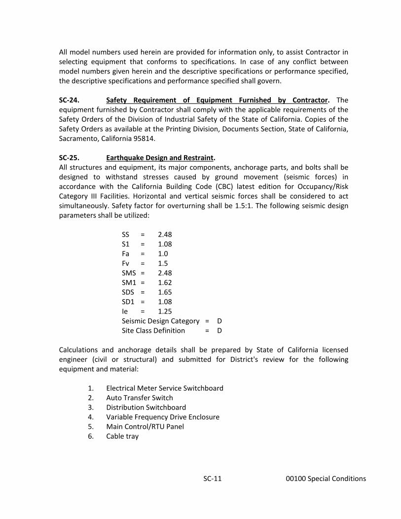
SC-11 00100 Special Conditions
All model numbers used herein are provided for information only, to assist Contractor in selecting equipment that conforms to specifications. In case of any conflict between model numbers given herein and the descriptive specifications or performance specified, the descriptive specifications and performance specified shall govern. SC-24. Safety Requirement of Equipment Furnished by Contractor. The equipment furnished by Contractor shall comply with the applicable requirements of the Safety Orders of the Division of Industrial Safety of the State of California. Copies of the Safety Orders as available at the Printing Division, Documents Section, State of California, Sacramento, California 95814. SC-25. Earthquake Design and Restraint. All structures and equipment, its major components, anchorage parts, and bolts shall be designed to withstand stresses caused by ground movement (seismic forces) in accordance with the California Building Code (CBC) latest edition for Occupancy/Risk Category III Facilities. Horizontal and vertical seismic forces shall be considered to act simultaneously. Safety factor for overturning shall be 1.5:1. The following seismic design parameters shall be utilized:
SS = 2.48 S1 = 1.08 Fa = 1.0 Fv = 1.5 SMS = 2.48 SM1 = 1.62 SDS = 1.65 SD1 = 1.08 Ie = 1.25 Seismic Design Category = D Site Class Definition = D
Calculations and anchorage details shall be prepared by State of California licensed engineer (civil or structural) and submitted for District's review for the following equipment and material:
1. Electrical Meter Service Switchboard 2. Auto Transfer Switch 3. Distribution Switchboard 4. Variable Frequency Drive Enclosure 5. Main Control/RTU Panel 6. Cable tray
SC-12 00100 Special Conditions
SC-26. Preservation of Paved Surfaces, Restoration of Work Site, and Disposal of Spoil and Waste Materials. Contractor shall perform his operations so that existing roads and other paved surfaces adjacent to or in the vicinity of the work site are not damaged. Contractor shall repair any damaged pavement which results from his operations (except that which is specifically a part of the Contract Work) to the satisfaction of the District, all at his expense. All work sites shall be restored to pre-job conditions and shall meet the requirements of the District and property owners. District is obligated to keep visual impact of the work sites to a minimum; therefore, Contractor is required to restore all areas altered by construction to pre-existing conditions. Such areas shall include, but shall not be limited to, areas used for travel, parking, and storage of vehicles, equipment and materials. Contractor shall be responsible for the proper disposal of all waste materials resulting from his operations, including equipment and material specified to be demolished, rubbish, packaging materials, discarded equipment parts, and damaged construction materials, in a manner and at locations suitable to the District and all health and other regulatory agencies. SC-27. Electrical Service. Installation of SCE equipment shall be by an SCE or SCE approved electrical contractor. Said Contractor shall construct a new electric service meter and CTs in the meter switchboard per Southern California Edison (SCE) requirements and in accordance with Contract Documents. Contractor shall coordinate all required work with SCE and District, including: (1) removal of existing secondary conductor and meter switchboard; and (2) installation of new secondary conductors and installation of new meter switchboard, and appurtenances. A copy of the approved SCE Service Plans for the proposed new electrical service and removal of the existing electrical service are provided in Appendix B herein. SCE shall remove and dispose of existing meter, CT’s and secondary service cables. Existing secondary conduit will be abandoned in place. All electrical service material and equipment shall be in strict accordance with SCE requirements. Prior to commencing construction of electrical service facilities, Contractor shall submit shop drawings of proposed material and equipment to SCE and District for review and approval. Contractor's work will be inspected by SCE's Inspector and the District's Inspector. District will pay directly all SCE fees required for new service. Conduit installation from the edge of the transformer pad to transformer termination and tie-in to the existing transformer shall be performed by SCE staff or SCE approved electrical contractor.

SC-13 00100 Special Conditions
SC-28. Spoil Material. Excess soils from excavation shall be spoiled entirely at Contractor's expense off the project site to an approved disposal area through the County or City. In no instance shall excess spoil become a public nuisance or threat to public safety. SC-29. Local Conditions. The Contractor shall assess, by personal investigation, local conditions affecting the work. Neither the information contained in this section nor that derived from any maps or plats, or from the District or employees shall act to relieve the Contractor of any responsibility herein or from fulfilling any and all of the terms and requirements of this Contract. Nuisance water, such as rainfall, irrigation water, or local surface runoff may occur within construction areas during the period of construction under this contract. The Contractor, by submitting his bid, will be held responsible for having investigated the risks arising from such water and shall take all due measures to prevent delays in progress of the work caused by such waters. SC-30. Storage of Materials and Equipment and Site Security. Contractor may utilize available land at the booster site for storage of materials and equipment. Contractor shall coordinate the location of material and equipment storage with the District Inspector. Contractor has the option to secure their own storage yard for materials and equipment. However, if private or public property is used, the Contractor must obtain written permission from affected property owners and/or agencies in advance of moving said material or equipment onto offsite property. A copy of the letter from the private owner granting permission shall be submitted to the District prior to use of the site. The District will not approve the use of any property unless it can be considered "previously disturbed" in accordance with CEQA guidelines. The Contractor shall be responsible for providing all security measures necessary to secure the stored materials or equipment and to protect the construction area regardless of whether it is stored on District property or Contractor acquired property. The District is not responsible for items lost, damaged or stolen from the secured site or for injuries to the public due to unsafe or unsecured conditions. SC-31. Sanitation. For the entire period of construction, Contractor shall provide portable toilets for his personnel at the pump station site. SC-32. Kingfisher Programmable Logic Controller (OFCI). The District will furnish the Kingfisher PLC and the Contractor shall install same in the contractor furnished RTU enclosure. The District will program the PLC after Contractor demonstrates satisfactory connection and operation of all field devices and equipment.

SC-14 00100 Special Conditions
District will provide an RTU for temporary use during construction to automate facility. Contractor will be required to install the temporary RTU, with the same installation requirements for the permanent RTU (as applicable). The District will program and integrate the temporary RTU with the SCADA system within the estimated 3-day shutdown shown in Item No. 1 of the Shutdown Coordination Table. Contractor shall complete installation of all Contractor-furnished items, including, but not limited to, the RTU enclosure, antenna equipment, and related telemetry appurtenances a minimum of 14 calendar days prior to startup and testing of any pump station equipment to allow District's staff adequate time to program and test District-furnished equipment. Contractor shall provide assistance (as necessary) at no additional cost to the District during testing of said equipment if the installation of the equipment is determined to be deficient. SC-33. Existing Coatings. The District has sampled the existing coatings at the Redlands and Cottonwood Booster site. The results of these analyses are included as part of this specification in Appendix C. Contractor shall furnish all labor, equipment, and materials, and perform all operations necessary for proper abatement and disposal of hazardous materials in strict compliance with all applicable state and federal statutes. Acquisition of all required permits, and the disposal of waste coatings and abrasives shall be at the Contractor's expense. The District shall be furnished with all documentation related to spent abrasives and waste coating (paint) debris, including analytical results of concentrations per the California Administrative Manual, Title 22 (CAM 17) metals. SC-34. Electrical Equipment Dimensions. The plans show conceptual dimensions of the electrical equipment based on information received from manufacturers. Contractor shall be responsible for verifying that the electrical equipment shown on the contract plans fits within the proposed space allotment. SC-35. Asbestos Survey. The District performed an Asbestos Survey for the project. The results are included in Appendix F. Contractor shall furnish all labor, equipment, and materials, and perform all operations necessary for proper abatement and disposal of hazardous materials in strict compliance with all applicable State and Federal statutes. Acquisition of all required permits, and the disposal of asbestos containing waste and abrasives shall be at the Contractor’s expense. The District shall be furnished with all documentation related to asbestos containing debris, including analytical results of concentrations per the State and Federal regulations. Additionally, the District will be named the “Generator” and will aid the Contractor in submitting the manifest to the proper authority.

SC-15 00100 Special Conditions
SC-36. Salvage Items. Equipment and facilities to be salvaged for the Owner include the following:
• Remote Telemetry Unit • Salvage Equipment as indicated on drawing D-1
Demolition shall include the cost of salvage of specified items and equipment, including delivery to the Owner's storage yard located at 2270 Trumble Road, Perris, California. Contractor shall coordinate delivery of salvaged items with District inspector. SC-37. SCE Work. Contractor shall be advised that SCE may take up to 30 calendar days after equipment green tag and official notification to complete installation of the new electrical meter. Contractor shall allow thirty (30) days in the construction schedule after equipment green tag and SCE notification for SCE to install and energize the new meter. Reference Special Condition SC-27. SC-38. Noise Control Requirements. Noise suppression shall be practiced at all time to minimize disturbance to persons living or working nearby, and to the general public. The measures to be used in effecting noise suppression shall include, but are not limited to, equipping all internal combustion engines with critical residential silencers (mufflers), sound blankets shielding noise-producing equipment from nearest areas of human occupancy by locating in such positions as to direct greatest noise emissions away from such areas, and conducting operations in the most effective manner to minimize noise generation consistent with the execution of the contract in a timely and economic manner. Noise control barrier walls and equipment shall be installed as needed to meet local noise regulations/ordinances. SC-39. Temp Power & Controls. Contractor shall complete a live 7-day operational demonstration to the satisfaction of the District prior to disconnecting and LOTO electrical equipment for Pumps 2 & 3. SC-40. Soils or Geotechnical Reports, or Reference to. A preliminary soil investigation was performed by others to evaluate the surface and subsurface conditions at the site in order to provide recommendations for engineering design. Said report is provided in Appendix C of these Specifications.

SC-16 00100 Special Conditions
Where investigations of subsurface conditions have been made by the District in respect to foundation or other structural design, and that information is shown in the plans, said information represents only the statement by the District as to the character of material which has been actually encountered by it in its investigation, and is only included for the convenience of bidders. Investigations of subsurface conditions are made for the purpose of design, and the District assumes no responsibility whatever in respect to the sufficiency or accuracy of borings or of the log of test borings or other preliminary investigations, or of the interpretation thereof, and there is no guaranty either expressed or implied, that the conditions indicated are representative of those existing throughout the work, or any part of it, or that unlooked for developments may not occur. Making such information available to bidders is not be construed in any way as waiver of the provisions of the first part of this article and bidders must satisfy themselves through their own investigations as to conditions to be encountered.

P-1 00200 Section P Contract Drawings
EASTERN MUNICIPAL WATER DISTRICT SPECIFICATION NO. 1368W
REDLANDS AND COTTONWOOD BOOSTER ELECTRICAL REPLACEMENT
SECTION P - CONTRACT DRAWINGS
P-01. General. The location of the work, its general nature and extent, the outline of the land owned or controlled by the District and the form and general dimensions of the facilities (ie. pipelines, appurtenances, etc.) are as shown on the drawings attached and made a part of this Specification as listed below. P-02. Standard Drawings. Drawing Number Drawing Title D-672 Chain Link Fence Details P-03. Construction Drawings. Drawing Number Drawing Title D-61334 Title Sheet, Vicinity Map, and Location Map D-61335 General Notes, Symbols, Legend, Abbreviations, and Sheet
Index D-61336 Temporary Power Plan and Demolition Plan D-61337 Civil Site Plan D-61338 Civil Details 1 D-61339 Civil Details 2 D-61340 Engine Demolition Plan D-61341 Electrical Symbols, Notes, and Abbreviations D-61342 Single Line Diagram D-61343 Switchboards and MCP Panel Elevations and Floor Plan D-61344 VFD Elevations and Floor Plan D-61345 Electrical Site Plan D-61346 Electrical Power Plan D-61347 Electrical Conduit and Cable Schedule D-61348 Pump Control Schematic Diagram D-61349 RTU Connection Diagram D-61350 Electrical Details D-61351 P&ID Legend D-61352 P&ID

P-2 00200 Section P Contract Drawings
[PAGE LEFT INTENTIONALLY BLANK]


PAGE LEFT INTENTIONALLY BLANK

Rev: 9/22/20
SPECIFICATIONS - DETAILED PROVISIONS Section 01000 - General Safety Requirements
C O N T E N T S
1.01 RESPONSIBILITY ......................................................................................................................... 1 1.01A SAFETY AND HEALTH ................................................................................................................. 1 1.02 OTHER CODES AND STATUTES .................................................................................................. 2 1.03 SUBCONTRACTS ........................................................................................................................ 2 1.04 DIFFERING OPINIONS ................................................................................................................ 3 1.05 PRECONSTRUCTION SAFETY MEETING ..................................................................................... 3 1.06 SAFETY PROGRAMS ................................................................................................................... 4 1.07 SAFETY PROGRAM REVIEW ....................................................................................................... 4 1.08 JOINT SAFETY POLICY MEETING ................................................................................................ 4 1.09 SAFETY PERSONNEL .................................................................................................................. 4 1.10 SAFETY INSPECTION .................................................................................................................. 5 1.11 ACCIDENT/INJURY/ILLNESS INVESTIGATION AND REPORTING ................................................ 5 1.12 INVESTIGATION/REPORTING .................................................................................................... 6 1.13 MONTHLY ACCIDENT STATISTICAL REPORT .............................................................................. 6 1.14 HOUSEKEEPING ......................................................................................................................... 6 1.15 HAZARDOUS MATERIALS AND HAZARDOUS WASTE ................................................................ 7 1.16 GENERAL ................................................................................................................................... 8 1.17 CERTIFICATION .......................................................................................................................... 8 1.18 EMWD LOCKOUT/TAGOUT PROCEDURE .................................................................................. 8 1.19 EXPERIENCE MODIFICATION RATING ....................................................................................... 8 1.20 WORKERS COMPENSATION RECORDS ...................................................................................... 8 1.21 CONFINED SPACE ENTRY REQUIREMENTS ............................................................................... 8 ATTACHMENTS ..................................................................................................................................... 9 • EXHIBIT “A” – (EN-87) NOTICE OF UNSAFE CONDITION • EXHIBIT “B” – (EN-84) SPECIFIC OPERATING SAFETY PROCEDURE • EXHIBIT “C” – (EN-85) REPORT OF INJURY • EXHIBIT “D” – (EN-89) CONTRACTOR MONTHLY SUMMARY OF OCCUPATIONAL
INJURIES/ILLNESSES EXPENSE • EXHIBIT “E” - EMWD CONFINED SPACE ENTRY POLICY

[PAGE LEFT INTENTIONALLY BLANK]

General Safety Requirements Section 01000 – 1
SECTION 01000 GENERAL SAFETY REQUIREMENTS
1.01 RESPONSIBILITY
The contractor is responsible for ensuring that all activities in connection with the work including, but not limited to, labor, materials, and equipment, conform fully with the standards referenced herein. This requirement applies to all activities performed, operated, maintained or constructed by the contractor, sub-contractor, supplier, or any other agent of the contractor performing work. Further, the contractor, his subcontractor, suppliers, and any other agents shall not require any employee, or other worker in connection with the performance of the contract, to engage in work under conditions which are unsanitary, hazardous, dangerous to an employee’s health or safety or otherwise in violation of any applicable federal, state, or local law or regulation in regard to occupational safety.
1.01A SAFETY AND HEALTH
The Contractor shall conform to all applicable occupational safety and health standards, rules, regulations and orders established by local agencies, State of California, and California Division of Occupational Safety and Health Construction Safety Regulations (Cal OSHA), including obtaining permits required by California Code of Regulations, Title 8, Section 341 and 341 (a). §1527. Washing Facilities, Food Handling, and Temporary Sleeping Quarters. WASHING FACILITIES
A. GENERAL. Washing facilities shall be provided as follows: A minimum of one washing station shall be provided for each twenty employees or fraction thereof. Washing stations provided to comply with this requirement shall at all times: 1. Be maintained in a clean and sanitary condition;
2. Have an adequate supply of water for effective washing;
3. Have a readily available supply of soap or other suitable cleansing agent;
4. Have a readily available supply of single-use towels or a warm-air blower;
5. Be located and arranged so that any time a toilet is used, the user can readily
wash; 6. When provided in association with a nonwater carriage toilet facility in
accordance with Section 1526(c),

General Safety Requirements Section 01000 – 2
7. Provide a sign or equivalent method of notice indicating that the water is intended for washing; and
8. Be located outside of the toilet facility and not attached to it.
B. EXCEPTION to subsection (a)(1)(F)(2.): Where there are less than 5 employees, and only one toilet facility is provided, the required washing facility may be located inside of the toilet facility.
C. EXCEPTION to subsection (a)(1): Mobile crews having readily available transportation to a nearby toilet and washing facility.
D. WASHING FACILITIES FOR HAZARDOUS SUBSTANCES. Where employees are engaging in the application of paints, or coatings, or in other operations involving substances which may be harmful to the employees, washing facilities shall be provided in near proximity to the worksite and shall be so equipped as to enable employees to remove such substances. Facilities provided to comply with this requirement shall at all times: 1. Be maintained in a clean and sanitary condition;
2. Have an adequate supply of water sufficient for effective removal of the
hazardous substance from skin surfaces; and
3. Have a readily available supply of soap, and where necessary to effect removal, special cleansing compounds designed specifically for removal of the hazardous substance from skin surfaces; and
4. Have a readily available supply of single use towels or a warm-air blower.
1.02 OTHER CODES AND STATUTES
In addition to the standards and requirements detailed herein, contractors and subcontractors shall comply with applicable provisions of Federal, State, and municipal safety, health, and sanitation statutes and codes. In the event there is a conflict between the provisions of the Safety and Health Regulations for Construction promulgated by the U.S. Department of Labor in Title 29 CFR Part 1926, Occupational Safety and Health Act (OSHA), or the California Occupational Safety and Health Act regulations in the California Labor Code Section 6300 et seq. (Cal. OSHA), the more stringent provision shall prevail.
1.03 SUBCONTRACTS
Contractors shall include provisions for compliance with the health and safety requirements, as referenced in this Section 01000, in the terms and conditions of all contracts, subcontracts, supply contracts, and all other contractor arrangements for performance of the work.

General Safety Requirements Section 01000 – 3
1.04 DIFFERING OPINIONS
Differing opinions between the contractor and District on adequacy of existing or proposed protective measures, equipment, procedures, or devices shall be resolved as follows:
A. Upon receipt of a written notice from the District regarding an issue in question, (see
Standard Form Exhibit “A”), the contractor shall not start or continue the measure, procedure, equipment, or devices, or expose employees to associated hazards until the differences have been resolved.
B. Upon resolution of the differing opinions, either with or without input from an independent professional safety engineer, Certified Safety Professional (CSP), or other safety expert, the questionable measure, procedure, equipment, or device shall be brought into conformance with the written agreed-upon solution. Only personnel required to complete remedial work shall be exposed to the associated hazard, and then only in a manner conforming to all safety requirements.
C. Obtaining engineering data or retaining the services of an independent professional engineer to assist in resolving the issue(s) remains a contractor responsibility.
1.05 PRECONSTRUCTION SAFETY MEETING
Representatives of the contractor shall meet with the District prior to the start of construction to review the respective safety requirements and to discuss implementation of all health and safety provisions pertinent to the work under contract, including safety training status of equipment operators, etc. The contractor shall be prepared to discuss, in detail, the measures he intends to take to control the possible hazards incident to the major phases of the work under contract and to comply with contractual obligations. This meeting will be devoted to discussing the manner in which the contractor intends to administer his health and safety program and delegate the responsibilities for implementing the program. A Specific Operating Safety Procedure (EN-84) and an Injury & Illness Prevention Program must be submitted to the District at the Pre-Construction conference for acceptance by the District prior to the start of construction. The Contractor shall identify any safety organization, safety team, or safety person within the Contractor’s organization, complete with contact name and telephone number. For assistance in preparing your Injury and Illness Prevention Program, go to http://www.dir.ca.gov/dosh/etools/09-031/index.htm The Injury & Illness Prevention Program shall be submitted in Electronic Format as follows: Submit all information in searchable PDF format; PC compatible using Windows XP operating system. All information provided shall be consolidated to one portable document file (PDF) in the latest version of Adobe Acrobat, with a Table of Contents and Bookmarks for each major section.

General Safety Requirements Section 01000 – 4
1.06 SAFETY PROGRAMS The prime contractor shall prepare a comprehensive written safety program covering all aspects of onsite construction operations and activities associated with each respective contract. Further, unless adequately covered in the original plan, a supplementary detailed plan will be submitted prior to start of each major phase of work or when requested by the District. In no case will onsite work commence until the program or appropriate supplementary submittals have been approved by the District. Initial and supplementary submittals shall include a timetable for completing the required, detailed, and specific operating procedures with hazard analysis. Approval by the District of initial and supplementary programs submitted by contractor only signifies that the submittals generally conform to the requirements contained and referenced herein, and shall not constitute any acceptance or other obligation of the District for the contractor’s responsibilities for said programs. Said approval does not relieve the contractor of the responsibility of providing employees with a safe and healthful work environment, or complying fully with all the above requirements. For a project- specific safety plan outline for Contractor’s use, see Exhibit “B” (Specific Operating Procedure - including Hazard Analysis).
1.07 SAFETY PROGRAM REVIEW
Following the above preconstruction safety meeting and development of the Safety Program, a second meeting shall be held to review the contractor’s written safety program. The contractor’s principal onsite representative, the general superintendent, and his safety representative shall attend this meeting.
1.08 JOINT SAFETY POLICY MEETING
The District, the contractor’s principal onsite representative, and designated staff members shall participate in scheduled monthly safety meetings. These meetings shall be used to review the effectiveness of the contractor’s safety effort, to resolve health and safety problems relating to current operations, and to provide a forum for planning safe future construction activities. Meeting minutes shall be prepared by the Contractor and maintained in a manner prescribed by the District.
1.09 SAFETY PERSONNEL
When the contract does not require the services of a full-time safety engineer, the contractor shall designate a competent and dependable supervisory employee, acceptable to the District, to administer this safety program. However, should the contractor’s safety effort be considered inadequate, the District has the option to require the contractor to employ a full-time qualified safety engineer in lieu of a safety representative. The hiring of a full-time safety engineer shall be at the sole cost and expense of contractor and said hiring shall not entitle contractor to additional compensation.

General Safety Requirements Section 01000 – 5
1.10 SAFETY INSPECTION
The contractor shall provide for weekly safety inspections of the worksites, materials, and equipment by competent employees. Detailed written inspection records shall be maintained and available for review by the District. Prior to the use of any gauges which monitor atmospheric hazards, the contractor’s competent person will verify that the gauge is in current calibration. This will be documented on the District’s resident inspector’s daily report form.
1.11 ACCIDENT/INJURY/ILLNESS INVESTIGATION AND REPORTING
DEFINITIONS:
A. Serious Accidents/Incidents Any occurrence of a job-related nature including, but not limited to, suicide or homicide attempts, heart attacks, and occupational injuries or diseases which result in: 1. An employee or agent of District, contractor, subcontractor, or supplier suffering
death, permanent total disability, complete and/or permanent loss of an eye, hand, foot, or major organ.
2. Hospitalization for five or more days of an employee or agent of District and/or contractor, subcontractor, or supplier, or one or more employees in critical condition.
3. Fires or property damage resulting in a loss of $25,000 or more.
4. Third party injuries, death, or substantial property losses that result or could result in claims against the District.
B. Nonserious Accidents/Incidents All other personal and/or property damage accidents/incidents except first aid cases and property damage losses below $2,500.
C. Potential Serious Accidents/Incidents Accidental occurrences or near misses with the potential to be a serious accident/incident such as major equipment failures, contact with high voltage lines, spills of or personal contacts with excessive amounts of toxic or hazardous materials, slides, cave-ins, etc.

General Safety Requirements Section 01000 – 6
1.12 INVESTIGATION/REPORTING
A. Serious accident/incidents shall be reported immediately to the District and appropriate contractor field supervisor. Providing or obtaining appropriate medical and emergency assistance and notification of coroner, safety, and law enforcement agencies, and family members remain a contractor responsibility. Except for rescue and emergency measures, the scene of the accident/incident shall not be disturbed or the operation resumed until authorized by District. The contractor shall assist and cooperate fully with the District in conducting the investigations of the accident/incident and assure availability of all information, personnel, and data pertinent to the investigation. The contractor shall, when ordered by the District, conduct or have conducted a separate and complete independent investigation of the accident/incident, and submit a comprehensive report of findings and recommendations to the District. The contractor shall arrange and be financially responsible for the independent investigation and any equipment or material inspections or tests, or diagnostic studies required by the District or contractor investigators. Further, Contractor’s Report of Recordable Injury/Illness (See Exhibit “C”) shall be completed and submitted to the District for each injured person.
B. Nonserious accident/incidents will be reported immediately to the contractor’s supervisor delegated authority to arrange for medical assistance and/or investigate the accident/incidents. Immediately following arrangements for required medical assistance, the responsible supervisor will investigate the accident/incident. Within three working days following the accident/incident, the contractor will submit to the District, a completed Contractor’s Report of Recordable Injury/Illness (see Exhibit “C”) for all personal injuries, and a comprehensive narrative report for property damage accidents.
C. Potentially serious accident/incidents shall be reported immediately to the District. The contractor’s involved equipment and/or worksite shall remain secured until the contractor has completed an acceptable comprehensive investigation. Within five days following the investigation, a detailed written investigation report will be submitted to the District.
1.13 MONTHLY ACCIDENT STATISTICAL REPORT
After any incident or accident the contractor shall submit a standard form entitled Contractor Summary of Occupational Injuries/Illnesses Experience (See Exhibit “D”) or equivalent form acceptable to the District for the previous 12 month period.
1.14 HOUSEKEEPING
Good housekeeping, including provision and facilities for routine scrap removal, shall be maintained in all areas within the contractor’s scope of operation.

General Safety Requirements Section 01000 – 7
1.15 HAZARDOUS MATERIALS AND HAZARDOUS WASTE
A. Contractor shall comply with the Global Harmonization System (GHS) requirements in addition to complying with the Cal OSHA Hazard Communication regulation and EMWD’s Hazard Communication Program.
B. Contractor shall identify the name(s) of the individuals(s) who are responsible for ensuring compliance with the contractor’s Hazard Communication and Global Harmonization System policies. The name(s) of the individual(s) shall be provided at the pre-job conference with the District’s representatives.
C. Contractor shall be solely responsible for providing and posting of Hazard Communication and GHS warning, symbols and/or placards at the job site. This applies to the chemicals, compounds and/or substances brought on to the District’s property and stored during the construction process.
Chemicals, compounds and/or substances that are not used in the construction activities on the District’s property shall not be stored on the property. Prior to bringing any new chemicals, compounds and/or substances on to the District’s property that were not identified prior to the start of on site activities, the contractor shall notify the District’s representative of the new chemicals, compounds or substances.
D. The independent contractor shall be solely responsible for enforcing the HAZCOM and GHS requirements with its subcontractors, vendors and/or consultants.
E. It is the responsibility of the contractor to provide Hazard Communication Training for its employees. The training shall include, at a minimum, the District’s substances, compounds and/or chemicals the workers can be exposed to during their time on the project; and the chemicals, substances and/or compounds the contractor brings on to the construction project.
F. Any safety or health concerns brought to the contractor’s attention by District personnel or consultants hired by the District, with respect to the Contractor Hazcom Coordination Procedure, shall be immediately addressed by the contractor. The contractor will be solely responsible for taking appropriate corrective action and notifying the District of the action taken.
G. The contractor shall clean up any spills in accordance with the manufacturer’s recommendations, the SDS and/or EPA requirements.
H. The contractor shall properly dispose of any materials, chemicals, compounds and/or substances in accordance with current safety & health regulations. DO NOT PLACE ANY HAZARDOUS MATERIAL INTO THE DISTRICTS’S TRASH CONTAINERS OR DUMPSTERS. DO NOT BURY OR HIDE ANY CHEMICALS, COMPOUNDS AND/OR SUBSTANCES ON DISTRICT PROPERTY.

General Safety Requirements Section 01000 – 8
1.16 GENERAL
Intoxicating beverages and narcotics shall not be permitted or used on construction sites. Persons under the influence of alcohol of narcotics shall not be permitted on the site. Firearms shall not be permitted on the construction site without prior approval of the District.
1.17 CERTIFICATION
Design of major critical facilities, equipment, support structures, or systems, embankments, shoring systems, formwork (falsework) built or provided by the contractor for his use shall be certified as structurally suitable for the use intended under the specifications. This certification shall be made in writing by the manufacturer or a registered professional engineer competent in these fields and shall be submitted to the District prior to erection or use of such facilities, equipment or support systems.
1.18 EMWD LOCKOUT/TAGOUT PROCEDURE
The Contractor shall make himself familiar with the District’s lockout/tagout procedure to isolate energy sources (mechanical, pneumatic, electrical, hydraulic, physical or chemical). The Contractor MUST coordinate through a qualified District representative (Inspector) a minimum of forty-eight (48) hours prior to requiring a lockout/tagout. The District Representative (Inspector) will arrange to have any energy source as described above locked out by an authorized employee in accordance with the District’s procedure. In case there is any violation of the District’s lockout/tagout procedure the Contractor will be directed to cease operations related to the unsafe condition, measure, procedure, equipment or device and will be issued a Notice of Unsafe Condition.
1.19 EXPERIENCE MODIFICATION RATING
The Contractor shall, prior to the Pre-Construction Safety Meeting, submit a current copy of the Experience Modification Rating for himself and any listed sub-contractor. This information will be reviewed at the Pre-Construction Safety Meeting.
1.20 WORKERS COMPENSATION RECORDS
The Contractor shall submit Workers Compensation Records for the past 2 years (Log and Summary of Occupational Injuries and Illnesses). This information will be reviewed at the Pre-Construction Safety Meeting.
1.21 CONFINED SPACE ENTRY REQUIREMENTS
When working in, or connecting to existing systems in operation, the required safety provisions for work in an operating system will be enforced, including provisions for working in confined air spaces. Contractor shall comply with EMWD’s Confined space Entry Policy attached hereto (see Exhibit E).
END OF SECTION 01000
General Safety Requirements Section 01000 – 9
ATTACHMENTS
• EXHIBIT “A” – (EN-87) NOTICE OF UNSAFE CONDITION
• EXHIBIT “B” – (EN-84) SPECIFIC OPERATING SAFETY PROCEDURE
• EXHIBIT “C” – (EN-85) REPORT OF INJURY
• EXHIBIT “D” – (EN-89) CONTRACTOR MONTHLY SUMMARY OF OCCUPATIONAL INJURIES/ILLNESSES EXPENSE
• EXHIBIT “E” – EMWD CONFINED SPACE ENTRY POLICY

General Safety Requirements Section 01000 – 10
[PAGE LEFT INTENTIONALLY BLANK]
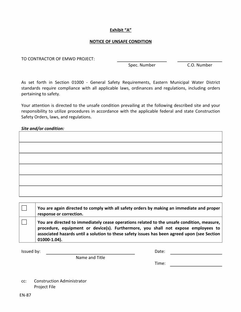
EN-87
Exhibit “A”
NOTICE OF UNSAFE CONDITION
TO CONTRACTOR OF EMWD PROJECT: Spec. Number C.O. Number As set forth in Section 01000 - General Safety Requirements, Eastern Municipal Water District standards require compliance with all applicable laws, ordinances and regulations, including orders pertaining to safety. Your attention is directed to the unsafe condition prevailing at the following described site and your responsibility to utilize procedures in accordance with the applicable federal and state Construction Safety Orders, laws, and regulations. Site and/or condition:
You are again directed to comply with all safety orders by making an immediate and proper response or correction.
You are directed to immediately cease operations related to the unsafe condition, measure, procedure, equipment or device(s). Furthermore, you shall not expose employees to associated hazards until a solution to these safety issues has been agreed upon (see Section 01000-1.04).
Issued by: Date: Name and Title Time: cc: Construction Administrator Project File

[PAGE LEFT INTENTIONALLY BLANK]

EN-8
4
Ex
hibi
t “B”
SPEC
IFIC
OPE
RATI
NG
SAF
ETY
PRO
CEDU
RE
(INCL
UDI
NG
HAZA
RD A
NAL
YSIS
)
PRO
JECT
:
SPEC
. NO
.
SPEC
IFIC
OPE
RATI
NG
PRO
CEDU
RE N
O.
OPE
RATI
ON
:
PAGE
OF
GEN
ERAL
INST
RUCT
ION
S:
DATE
:
PERS
ON
NEL
REQ
UIR
ED:
NO
TE: S
EE R
EVER
SE S
IDE
FOR
ADDI
TIO
NAL
INFO
RMAT
ION
SAFE
TY E
QU
IPM
ENT
AND
APPA
REL:
PRO
CEDU
RE D
EVEL
OPE
D BY
:
APPO
VED
BY:

OPE
RATI
ON
SEQ
UEN
CE
ASSO
CIAT
ED
HAZA
RD
EQU
IPM
ENT,
TO
OLS
O
R FA
CILI
TIES
SP
ECIA
L IN
STRU
CTIO
NS
OR
LIM
ITAT
ION
S RE
FERE
NCE

EN-84
1. GENERAL: Specific operating procedures (SOP) are designed as a planning tool. They are most
effective when developed jointly by the supervisor and employees engaged in the specific activity and/or operation. They provide excellent reference material for toolbox meetings and for instructing new employees on respective assignments and responsibility.
Their effectiveness in reducing accidents and improving job performance is directly related to the efforts expended in their development and timely revision.
2. ASSOCIATED HAZARDS: For each job step, ask yourself what accidents could happen to the
person doing the job step. You can get the answer by (1) observing the job, (2) discussing it with the operator, (3) recalling past accidents, or (4) a combination of the three. Ask yourself: can he be struck by or contacted by anything? can he strike against or come in contact with anything? can he be caught in, on, or between anything? can he fall? can he overexert? is he exposed to anything injurious, such as gas, radiation, welding rays, etc? (for example, acid, burns, fumes, dust).
3. EQUIPMENT, TOOLS, AIDS, OR FACILITIES: List type and number of tools and materials to be
used, i.e., two jack hammers, one compressor, two 2" diameter hoses, 100 feet in length, etc. 4. SPECIFIC INSTRUCTIONS OR LIMITATIONS: For each potential accident or hazard, ask yourself
how should the worker do the job step to avoid the potential accident, or what should he do or not do to avoid the accident. You can get your answers by (1) observing the job for leads, (2) discussing precautions with experienced job operators, (3) drawing on your experience, or (4) a combination of the three. Be sure to describe specifically the precautions a man must take. Don’t leave out important details. Number each separate recommended precaution with the same number you gave the potential accident (see appropriate column) that the precaution seeks to avoid. Use simple do or don’t statements to explain recommended precautions as if you were talking to the person.
For example: Only wirecore lifelines shall be used in highscaling operations. Block cable supported crane booms before removing section pins. Avoid such generalities as “Be careful,” “Be alert,” “Take caution,” etc.
5. REFERENCES: Reference specific material i.e., a SOP on highscaling should reference “Safety
Belts and Hardware,” and “Lifelines,” describe how to use a “Scaler’s Hitch,” etc.
6. SAFETY EQUIPMENT AND APPAREL: Specifically required safety equipment, devices, and apparel need to be listed, i.e., hard hat, eye and face protection, respirator protection, safety shoes, wearing apparel, hoist safety devices, air hose safety devices, etc.

[PAGE LEFT INTENTIONALLY BLANK]

EN-8
4
SAM
PLE
OF
PIPE
LIN
E SP
ECIF
IC O
PERA
TIN
G SA
FETY
PRO
CEDU
RE
SPEC
IFIC
OPE
RATI
NG
SAF
ETY
PRO
CEDU
RE
(INCL
UDI
NG
HAZA
RD A
NAL
YSIS
)
PRO
JECT
: (P
roje
ct T
itle)
SP
EC. N
O.
XXX
SPEC
IFIC
OPE
RATI
NG
PRO
CEDU
RE N
O.
(Spe
cify
)
OPE
RATI
ON
: (S
peci
fy)
PAGE
OF
GEN
ERAL
INST
RUCT
ION
S:
(Con
trac
tor’s
Nam
e) w
ill su
perv
ise
and
be re
spon
sibl
e fo
r pre
vent
ing
cont
act w
ith ra
w
Sew
er o
r any
oth
er h
azar
dous
mat
eria
l and
will
als
o m
onito
r and
con
firm
min
imum
requ
ired
tren
ch sl
opes
per
OSH
A
Requ
irem
ents
. Al
l soi
l typ
es a
nd tr
ench
slop
es w
ill b
e de
cide
d by
our
fiel
d fo
rem
an w
ho is
ons
ite c
ompe
tent
per
son.
DATE
: (T
oday
’s D
ate)
PE
RSO
NN
EL R
EQU
IRED
: (S
peci
fy H
ere)
NO
TE: S
EE R
EVER
SE S
IDE
FOR
ADDI
TIO
NAL
INFO
RMAT
ION
SAFE
TY E
QU
IPM
ENT
AND
APPA
REL:
(Sp
ecify
)
PRO
CEDU
RE D
EVEL
OPE
D BY
: (S
igna
ture
) AR
RPO
VED
BY:
(Sig
natu
re)

SAM
PLE
OF
PIPE
LIN
E SP
ECIF
IC O
PERA
TIN
G SA
FETY
PRO
CEDU
RE
OPE
RATI
ON
SEQ
UEN
CE
ASSO
CIAT
ED
HAZA
RD
EQU
IPM
ENT,
TO
OLS
O
R FA
CILI
TIES
SP
ECIA
L IN
STRU
CTIO
NS
OR
LIM
ITAT
ION
S RE
FERE
NCE
1.Ex
cava
tion,
Pipe
Inst
alla
tion,
ba
ckfil
l & c
ompa
ct
Pote
ntia
l uns
tabl
e ex
istin
g so
il co
nditi
ons
Tren
ches
will
be
slope
d or
sh
ored
per
OSH
A re
quire
men
ts
Hard
hat
s mus
t be
utili
zed
by
all f
ield
per
sonn
el.
Acce
ss
ladd
ers p
lace
d pe
r OSH
A re
quire
men
ts fo
r acc
ess i
n an
d ou
t of t
renc
hes.
Tre
nche
s bl
ocke
d an
d/or
bar
ricad
es a
s ne
eded
for p
ublic
safe
ty.
2. M
orta
ring
& B
itchm
astic
Co
atin
gs
Poss
ible
skin
con
tact
Sa
fety
Equ
ipm
ent t
o be
ut
ilize
d pe
r req
uire
men
ts
to m
eet f
ield
con
ditio
ns.
SDS
will
be
avai
labl
e on
site
to
revi
ew e
xpos
ure
effe
cts a
nd
follo
w fi
rst a
id in
stru
ctio
n.
3. T
raffi
c Co
ntro
l and
lane
cl
osur
es
Publ
ic &
Em
ploy
ee
Safe
ty
Arro
w b
oard
s, F
enci
ng,
Traf
fic p
late
s, p
rope
r co
nstr
uctio
n sig
nage
.
Per r
equi
rem
ents
of O
SHA
and
Cal-T
rans
traf
fic m
anua
l.
Safe
ty v
ests
/ora
nge
shirt
s to
be w
orn
in a
ll tr
affic
are
as.
4. R
emov
e Co
ncre
te
Flyi
ng c
oncr
ete
debr
is du
ring
dem
oliti
on
Hard
Hat
s, sa
fety
gog
gles
an
d du
st m
ask.
Pr
oper
ven
tilat
ion
mus
t be
mai
ntai
ned
durin
g sa
w c
uttin
g ex
istin
g co
ncre
te.
5. H
ydro
stat
ic P
ress
ure
Test
ing
High
pre
ssur
e te
stin
g eq
uipm
ent
Safe
ty e
quip
men
t to
be
utili
zed
per r
equi
rem
ents
to
mee
t fie
ld c
ondi
tions
.
SDS
will
be
avai
labl
e on
site
to
revi
ew e
xpos
ure
effe
cts a
nd
follo
w fi
rst a
id in
stru
ctio
n.

EN-8
4
OPE
RATI
ON
SEQ
UEN
CE
ASSO
CIAT
ED
HAZA
RD
EQU
IPM
ENT,
TO
OLS
O
R FA
CILI
TIES
SP
ECIA
L IN
STRU
CTIO
NS
OR
LIM
ITAT
ION
S RE
FERE
NCE
6. C
hlor
inat
ion
Poss
ible
skin
con
tact
Sa
fety
equ
ipm
ent t
o be
ut
ilize
d pe
r req
uire
men
ts
to m
eet f
ield
con
ditio
ns.
SDS
will
be
avai
labl
e on
site
to
revi
ew e
xpos
ure
effe
cts a
nd
follo
w fi
rst a
id in
stru
ctio
n.
Mai
ntai
n ad
equa
te v
entil
atio
n.
7. A
spha
lt Pa
ving
Bu
rns
Safe
ty e
quip
men
t to
be
utili
zed
per r
equi
rem
ents
to
mee
t fie
ld c
ondi
tions
.
SDS
will
be
avai
labl
e on
site
to
revi
ew e
xpos
ure
effe
cts a
nd
follo
w fi
rst a
id in
stru
ctio
n.
Mon
itor a
ll pa
ving
act
iviti
es
and
impl
emen
t saf
ety
requ
irem
ent p
er fi
eld
cond
ition
s for
bot
h em
ploy
ees
and
publ
ic sa
fety
.
8. C
oncr
ete
repa
ir Po
ssib
le sk
in c
onta
ct
& a
ir bo
rne
conc
rete
w
hile
chi
ppin
g
Safe
ty e
quip
men
t to
be
utili
zed
per r
equi
rem
ents
to
mee
t fie
ld c
ondi
tions
.
SDS
will
be
on si
te to
revi
ew
expo
sure
effe
cts a
nd fo
llow
fir
st a
id in
stru
ctio
n. M
aint
ain
adeq
uate
ven
tilat
ion.
9. D
ust c
ontr
ol &
saw
cut
ting
Visio
n Im
paire
d Ho
ses &
cor
ds k
ept t
o a
min
imum
leng
th.
Wea
r du
st m
asks
and
safe
ty
glas
ses.
SDS
will
be
avai
labl
e on
site
to
revi
ew e
xpos
ure
effe
cts a
nd
follo
w fi
rst a
id in
stru
ctio
n.
Mai
ntai
n ad
equa
te v
entil
atio
n.
10.
Cutt
ing
torc
hes
Expl
osiv
e/Ga
ses/
Fire
Fi
re E
xtin
guish
er
Fire
wat
ch/L
abor
er

OPE
RATI
ON
SEQ
UEN
CE
ASSO
CIAT
ED
HAZA
RD
EQU
IPM
ENT,
TO
OLS
O
R FA
CILI
TIES
SP
ECIA
L IN
STRU
CTIO
NS
OR
LIM
ITAT
ION
S RE
FERE
NCE
11.
Site
Cle
anne
ss
Trip
ping
Ke
ep to
ols o
rgan
ized
and
conc
entr
ated
En
d of
wor
k da
y pi
ck u
p ev
eryt
hing
12.
Emer
genc
y Ve
hicl
es
Gett
ing
to lo
catio
ns
Not
ify e
mer
genc
y se
rvic
es p
rior t
o co
nstr
uctio
n
Inst
ruct
all
empl
oyee
s on
proc
edur
es fo
r em
erge
ncy
traf
fic.
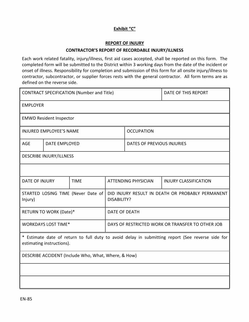
EN-85
Exhibit “C”
REPORT OF INJURY CONTRACTOR’S REPORT OF RECORDABLE INJURY/ILLNESS
Each work related fatality, injury/illness, first aid cases accepted, shall be reported on this form. The completed form will be submitted to the District within 3 working days from the date of the incident or onset of illness. Responsibility for completion and submission of this form for all onsite injury/illness to contractor, subcontractor, or supplier forces rests with the general contractor. All form terms are as defined on the reverse side.
CONTRACT SPECIFICATION (Number and Title) DATE OF THIS REPORT
EMPLOYER
EMWD Resident Inspector
INJURED EMPLOYEE’S NAME OCCUPATION
AGE DATE EMPLOYED DATES OF PREVIOUS INJURIES
DESCRIBE INJURY/ILLNESS
DATE OF INJURY TIME ATTENDING PHYSICIAN INJURY CLASSIFICATION
STARTED LOSING TIME (Never Date of Injury)
DID INJURY RESULT IN DEATH OR PROBABLY PERMANENT DISABILITY?
RETURN TO WORK (Date)* DATE OF DEATH
WORKDAYS LOST TIME* DAYS OF RESTRICTED WORK OR TRANSFER TO OTHER JOB
* Estimate date of return to full duty to avoid delay in submitting report (See reverse side for estimating instructions).
DESCRIBE ACCIDENT (Include Who, What, Where, & How)

EN-85
SUPERVISORY
OPINION
HOW COULD ACCIDENT HAVE BEEN PREVENTED?
(Signature) FOREMAN OR IMMEDIATE SUPERVISOR
NOTE: Information in this report is to be used for the prevention of accidents and is not intended as a basis for injury claims. Recordable injuries/illnesses and workdays lost and injury classification shall be as defined on reverse side of this form. Information in this report shall also be recorded on CAL-OSHA form 200.

EN-85
Work-related Injury/Illness: All injuries/illnesses to contractor, subcontractor, or supplier employees that result from an event or exposure on any contractor controlled worksite associated with the respective contract. Medical Cases: Injuries/illnesses are defined as medical cases if: (1) they can be treated only by a physician or licensed medical personnel, (2) they result in damage or harm to physical structure of a nonsuperficial nature (e.g., hairline fractures), (3) they impair bodily functions (i.e., normal use of senses, limbs, etc.), (4) they involve complications requiring follow-up medical treatment. The following are generally considered medical treatment: • Treatment of INFECTION • Application of ANTISEPTICS during second
or subsequent visits to medical personnel • Treatment of SECOND OR THIRD DEGREE
BURN(S) • Application of BUTTERFLY ADHESIVE
DRESSING(S) or STERISTRIPS in lieu of sutures
• Application of SUTURES (stitches) • Removal of FOREIGN BODIES EMBEDDED
IN EYE • Removal of FOREIGN BODIES from wound;
if procedure is COMPLICATED because of depth of embedment, size, or location
• Use of PRESCRIPTION MEDICATIONS (except a single dose administered on first visit for minor injury or discomfort)
• Use of hot or cold SOAKING THERAPY during second or subsequent visit to medical personnel
• Application of hot or cold COMPRESS(ES) during second or subsequent visit to medical personnel
• CUTTING AWAY DEAD SKIN (surgical debridement)
• Application of HEAT THERAPY during second or subsequent visit of medical personnel
• Use of WHIRLPOOL BATH THERAPY during second or subsequent visit of medical personnel
• POSITIVE X-RAY DIAGNOSIS (fractures, broken bones, etc.)
ADMISSION TO A HOSPITAL or equivalent medical facility for treatment or prolonged observation First Aid Cases: Cases (1) limited to one-time treatment and subsequent observation and (2) involve treatment of only minor injuries, not emergency treatment of serious injuries. Further, any one-time treatment and follow up visit for the sole purpose of observation of minor scratches, cuts, burns, splinters and so forth which do not ordinarily require medical care are classified as first aid treatment. Such one-time treatment and follow up visit for the purpose of observation is considered first aid even though provided by a physician or registered professional personnel. Visits to a doctor for an examination or other diagnostic procedure to determine whether the employee has an injury is classified as a first aid case if no injury is discovered or medical treatment is rendered. Conversely, if treatment is described and medical care is provided even by someone other than a physician or registered medical personnel, injury is classified as medical.
DEFINITION OF TERMS

EN-85
Other examples of first aid cases not requiring reporting unless they result in loss of consciousness, restriction of work, or motion, or transfer to another job are: • Application of ANTISEPTICS during first visit
to medical personnel • Treatment of FIRST DEGREE BURN(S) • Application of BANDAGE(S) during first visit
to medical personnel • Use of ELASTIC BANDAGES during first visit
to medical personnel • Removal of FOREIGN BODIES NOT
EMBEDDED IN EYE if only irrigation is required
• Removal of FOREIGN BODIES from wound, if procedure is UNCOMPLICATED, and is, for example, by tweezers or other simple technique
• Use of NONPRESCRIPTION MEDICATIONS AND administration of single dose of PRESCRIPTION MEDICATION on first visit for minor injury or discomfort
• SOAKING THERAPY ON INITIAL VISIT to medical personnel or removal of bandages by SOAKING
• Application of hot or cold COMPRESS(ES) during first visit to medical personnel
• Application of OINTMENTS to abrasions to prevent drying or cracking
• Application of HEAT THERAPY during first visit to medical personnel
• Use of WHIRLPOOL BATH THERAPY during first visit to medical personnel
• NEGATIVE X-RAY DIAGNOSIS • BRIEF OBSERVATION of injury during visit
to medical personnel Note: The administration of a TETANUS SHOT or BOOSTER, by itself, is not considered medical treatment. However, these shot are often given in conjunction with the more serious injuries. Therefore, injuries requiring
tetanus shots may be reportable for other reasons. Illness Cases: Occupational illness of an employee is any abnormal condition or disorder, other than one resulting from an occupational injury caused by exposure to environmental factors associated with employment. It includes acute and chronic illnesses or diseases which may be caused by inhalation, absorption, ingestion, or direct contact. Some conditions may be classified as either an injury or illness (but not both), depending upon the nature of the event that produced the condition. For example, a loss of hearing resulting from an explosion (an instantaneous event) is classified as an injury; the same condition arising from exposure to industrial noise over a period of time would be classified as an occupational illness. Similarly, irritation of the throat from exposure to chlorine fumes would be classified as an injury if it resulted from a ruptured tank and an illness if the exposure occurred over a period of time. The determination of illness or injury is based on the original event. Adverse reaction to a tetanus shot given for a laceration would be classified as an injury. Back cases should always be recorded as an injury. It should be noted that all occupational illnesses are reportable and recordable incidents regardless of the type of treatment provided. Fatalities: Work-related fatalities are reportable and recordable regardless of the time between the injury and the death or the length of the illness. Lost workdays attributable to the incident are not counted and any charged should be removed from the record.

EN-85
Lost Workdays: Lost workdays are defined as the number of workdays (consecutive or not), beyond the day of injury or onset of illness, the employee was away from work or limited to restricted work activity. The number of days away from work or days of restricted work activity does not include the day of injury or onset of illness or any days on which the employee would not have worked even though able to work, e.g., vacation days, days off, or holidays are not counted. Termination of employment may stop the count of lost workdays if unrelated to the employee’s injury or illness. If termination is related to injury/illness, an estimate of actual workdays lost shall be made. Retirements unrelated to injury or illness stop the count of lost workdays. Otherwise days lost are estimated. Lost workday counts cease when injury or illness is determined as totally disabling. Lost workday count stops when position employee was in when injured is abolished due to work completion, e.g., a dozer operator lost workdays count would not continue beyond last day of dozer operations on the project even if the operator still could not perform the operator functions. Restricted work: The number of workdays on which because of injury or illness: (1) the employee was assigned to another job on a temporary basis; or (2) the employee worked at a permanent job less than full time; Or (3) the employee worked at a permanently assigned job but could not perform all duties normally connected with it. Lost workday count stops when employee is permanently transferred to another permanently established position.
Contractor Controlled Worksite Associated with the Contract. The following and similar locations are considered contractor controlled worksites: All areas within the boundaries of the construction site including shops, plants, storage areas, haul roads, borrow and fill areas. All offsite locations (plants, shops, rock quarries, borrow areas, erection sites, etc.) used exclusively for supporting construction activities. All roads where traffic control is a contractor responsibility.


EN-8
9
Exhi
bit “
D”
CON
TRAC
TOR
MO
NTH
LY S
UM
MAR
Y O
F O
CCU
PATI
ON
AL IN
JURI
ES/I
LLN
ESSE
S EX
PEN
SE
Incl
uded
on
the
form
will
be
the
cont
ract
ors,
sub
cont
ract
ors,
and
sup
plie
rs o
nsite
inju
ry/il
lnes
s ex
perie
nce
for
the
repo
rtin
g 12
mon
th
perio
d. A
ll fo
rm te
rms a
re d
efin
ed o
n th
e ba
ck o
f thi
s for
m.
REPO
RTIN
G PE
RIO
D ST
ARTI
NG
ENDI
NG
CON
TRAC
TOR
SUBC
ON
TRAC
TOR
SUPP
LIER
– S
PEC.
NO
TY
PE O
F CO
NST
RUCT
ION
N
O.
EMPL
OYE
ES
MAN
-HO
URS
EX
POSU
RE
LOST
W
ORK
DAYS
RE
CORD
ABLE
CA
SES
INCI
DEN
T RA
TES
TOTA
L DE
ATHS
LOST
W
ORK
DAY
CASE
S TO
TAL
CASE
S
DEAT
H AN
D LO
ST
WO
RKDA
Y CA
SES
LOST
W
ORK
DAY
1 2
3 4
5 6
7 8
9 10
11
GEN
ERAL
CO
NTR
ACTO
R
NAM
E
SPEC
. NO
.
SUBC
ON
TRAC
TORS
SUPP
LIER
S
TOTA
L
CUM
MU
LATI
VE T
OTA
L

EN-8
9
[PAG
E LE
FT IN
TEN
TIO
NAL
LY B
LAN
K]

Column 1. Name of General Contractor and General Specification No. only. Combine all
subcontractor and/or supplier data under respective headings. Cumulative totals start from first day of onsite work under the specification.
Column 2. Major classification or type of work for contractor (Water pipeline, sewer pipeline, pump station, treatment plant, lift station, etc.). Minor classification for supplier or subcontractor (concrete work, earthwork, repair work, etc.).
Column 3. Average number of employees during reporting period. Include only onsite personnel. Number of subcontractor or supplier employees can be estimated by dividing number of estimated man-hours by 8 x number days of reporting period.
(Number of man-hours) (8 x number days of reporting period)
Column 4. Actual man-hours of onsite exposure. Do not include vacation time, holidays, down periods, etc.
Column 5. Lost workdays include actual days from work, restricted work days and days worked in another assigned position. (For detailed explanation of lost workdays and restricted work, see back of Exhibit “C”).
Column 6. Total of fatalities, lost workday cases, restricted work cases or transfer to other job cases, and medical cases reported on all forms “Contractor’s Report of Recordable Injury/Illness,” submitted during the reporting period covered by this form.
Column 7. Fatalities are charged to date of injury or onset of illness regardless of date of death.
Column 8. Includes all cases submitted during this reporting period of form “Contractors Report of Recordable Injury/Illness,” that show figures under headings entitled, “lost time, or restricted work or transfer to other job.” (see back of Exhibit “C”).
Columns 9, 10, 11
Incident rates are define as the number of injuries/illnesses or lost workdays related to a common exposure base-100 full-time workers or 200,000 man-hours (100 workmen x 40 hrs/week x 50 weeks/year = 200,000). These rates are calculated as follows:
Total Cases (column 9) = Total cases (column 6) x 200,000
Man-hours of Exposure (column 4)
Death and lost workday cases (column 10) =
Deaths (column 7) and lost workday cases (column 8) x 200,000
Man-hours of Exposure (column 4)
Lost workdays = Lost workdays (column 5) x 200,000
Man workdays of exposure (column 4)

EN-89
[PAGE LEFT INTENTIONALLY BLANK]

Confined Space Entry Procedure
Prepared By:
Safety, Risk and Emergency Management
Revision Date:
12/01/2017
Reviewed By:
Safety Committee

Confined Space Entry Procedure
05/01/2014 2
Table of Contents
1 Purpose .................................................................................................................................. 3
2 Scope and Application ........................................................................................................... 3
3 Definitions .............................................................................................................................. 3
4 Program Requirements .......................................................................................................... 9
5 Entry Instructions ................................................................................................................. 16
6 Duties And Responsibilities .................................................................................................. 18
7 Ventilation Requirements .................................................................................................... 20
8 Safety Equipment ................................................................................................................. 23
9 Permit Classification System ................................................................................................ 24
Appendix A Checklist of Requirements For Entry, Working in and Exiting Confined Spaces ....... 27
Appendix B Confined Space Entry Permit Decision Diagram ....................................................... 28
Appendix C Confined Space Permit .............................................................................................. 30
Appendix D Record Of Gas Analysis .............................................................................................. 31
Appendix E Riverside County Fire Department Facilities with Confined Space Rescue
Equipment and Training ....................................................................................................... 32
Appendix F Confined Space Inventory and Labeling .................................................................... 33
Appendix G Gas Detector (Monitor) Manufacturer’s Requirements ........................................... 35

Confined Space Entry Procedure
05/01/2014 3
1 Purpose
1.1 To establish a safe working procedure for District workers that meets or exceeds federal,
state, or local rules and regulations. This program was developed in accordance with
Cal/OSHA VPP Best Practices philosophy.
1.2 This Program is based on the regulatory requirements of the California Occupational
Safety and Health Administration Title 8 California Code of Regulations (CCR) Article 108,
Confined Space. The focus is to protect workers from exposure to hazards in confined
spaces.
NOTE: This EMWD procedure meets and exceeds the requirements of Title 8 General
Industry Safety Orders (GISO) and those of Title 8 Construction Safety Orders regarding
Confined Spaces.
2 Scope and Application
2.1 This procedure contains specific requirements for work practices to protect workers from
those hazards of entry into and work within a confined space. This procedure establishes
that all confined spaces must be evaluated to determine whether it is permit or non-
permit required prior to every entry.
3 Definitions
1 Attendant – An individual stationed outside the confined space who is trained as
required by this procedure and who monitors the authorized entrants inside the
permit required confined space. An attendant may not monitor more entrants or
more permit spaces than the entry permit specifically authorizes.
2 Authorized Entrant – Any worker who is authorized by the District to enter a confined
space to perform an assigned task. Authorized entrants may rotate duties, serving as
attendants. Only trained persons may enter the confined space during the term of the
permit.
3 Blanking or Blinding – The absolute closure of a pipe, line or duct, by fastening across
its bore a solid plate or “cap” which completely covers the bore; which extends to at
least the outer edge of the flange at which it is attached; and which is capable of
withstanding the maximum upstream pressure.

Confined Space Entry Procedure
05/01/2014 4
4 Biological Hazards – Microbial agents presenting a risk or potential risk to the
wellbeing of humans through inhalation, ingestion, skin absorption, or injection.
5 Bump Test – Testing an atmospheric monitoring device with a known concentration
of gases that the monitor is intended to test. The test is used to verify that the monitor
is within calibration parameters.
6 Calibration – A manual or electronic adjustment of an atmospheric monitoring device
to ensure testing parameter requirements of the manufacturer are met or exceeded.
7 Confined Space – A location must have all three of the following definitions to be a
“Confined Space.”
Is large enough and so configured that an worker can bodily enter and perform
assigned work; and
Has limited or restricted means for entry or exit for example but not limited to:
tanks, vessels, silos, storage bins, hoppers, vaults, pits, and ladder entry into
pumping plants or subgrade facilities are spaces that may have limited means of
entry; and
Is not designed for continuous worker occupancy. (Its primary function is other
than human occupancy.)
8 Double Block And Bleed – A method used to isolate a confined space from a line, duct
or pipe by physically closing two main valves on a piping system, and opening a
“vented to atmosphere” valve between them.
9 Emergency – Any occurrence, including a failure of monitoring device or hazard
control, internal or external to the confined space, which could endanger the entrant
or other workers.
10 Engulfment – The surrounding and effective capture of a person by a liquid or solid
substance.
11 Entry – An act by which a person intentionally passes through an opening into a
confined space. The entrant is considered to have entered as soon as any part of the
entrant’s body breaks the plane of an opening into the space.
12 Entry Permit – A document established by the District, the content of which is based
on the District’s hazard identification and evaluation for a confined space and is the
instrument by which the District can verify that all precautions have been met prior
to entry.

Confined Space Entry Procedure
05/01/2014 5
13 Entry Permit System – The written or printed document established by EMWD. The
permit will be signed by the Entry Supervisor and posted at the entrance to the
confined space.
The entry permit will include the name of the Attendant(s), the authorized Entrant(s),
the work to be performed, the tools and equipment being taken into the confined
space, the specific types of personal protective equipment to be used by the Entrants,
air monitoring readings, the date of entry, time of entry, time the permit is issued and
time the permit is scheduled to expire and be closed. Other information that the
Attendant and/or Entry Supervisor deems to be necessary will be written on the
permit.
14 Entry Supervisor – An appropriately trained worker who has been assigned the
responsibility of ensuring a safe confined space entry. (An entry supervisor shall not
enter the confined space as an entrant to perform work.)
15 Evacuation – An unaided emergency exit out of a confined space. This action may
result from the entrant’s own decision or by a command from outside the space by
the Attendant.
16 Fall Arrest/Rescue Device – A winch-type device that will quickly arrest a worker’s fall
and absorb much of the free fall energy. The fallen worker may then be winched to
safety using the hand crank system of the device. The cable from this device will attach
to the safety harness. The type(s) of fall protection equipment, including personnel
winches, will be determined by the Attendant and Entry Supervisor. The entrants will
use the fall protection equipment when there is an exposure of a worker falling during
entry or while exiting the confined space.
17 Gas Detector (Monitor) – Direct reading, four-gas monitor which measures oxygen
content, LEL, carbon monoxide, and hydrogen sulfide. This also includes specialty
monitors used to measure specific hazards (photo ionization detectors, metal oxide
probes, radiation detectors, etc.).
18 Hazardous Atmosphere – An atmosphere which exposes workers above established
exposure guidelines, to risk of death, incapacitation, injury or acute illness from one
or more of the following causes:
A flammable gas, vapor, or mist in excess of 10% of its lower explosive limit (LEL).
Atmospheres that read >0% LEL up to 10% can still present a hazard and the source
of the atmospheric reading must be determined and addressed;

Confined Space Entry Procedure
05/01/2014 6
An airborne combustible dust at a concentration over the permissible exposure
limit or that presents an explosion hazard by being above the minimum explosible
concentration (estimated by visual observation as completely obscuring vision at
a distance of 5 feet or less);
An atmospheric oxygen concentration below 19.5% or above 23.5%;
Carbon monoxide in excess of 25 PPM;
Hydrogen sulfide in excess of 10 PPM;
An atmospheric concentration of any substance for which a Cal OSHA permissible
exposure limit is exceeded and could result in worker exposure in excess of the
permissible exposure limit. When an air contaminant for which OSHA or Cal/OSHA
has not determined a permissible exposure limit which may be present in the
permit space atmosphere, the District shall consult other sources of information,
such as Safety Data Sheets which comply with the Hazard Communication
Standard guidance in establishing the acceptable environmental conditions for
entry by their workers; and
Any atmospheric condition recognized as immediately dangerous to life or health
(IDLH).
19 Hot Work Permit – The District’s written authorization to perform operations which
could produce a source of ignition, such as riveting, welding, cutting, use of abrasive
tools, burning, or heating.
20 Immediately Dangerous To Life or Health (IDLH) – Immediately dangerous to life or
health (IDLH) means any condition which poses an immediate threat of loss of life;
may result in irreversible injury and/or immediate-severe health effects; may result in
eye damage; irritation or other conditions which could impair escape from the permit
space.
21 Immediate-Severe Health Effects – Any acute clinical sign(s) of a serious, exposure-
related reaction manifested immediately or within 72 hours after exposure.
22 Large Enough And So Configured That A Worker Can Bodily Enter – The entryway
and space is large enough for any part of the worker’s body to enter in a manner that
could cause harm. The entire body of a worker does not need to enter for harm to
occur.
23 LEL – UEL – LEL: Lower Explosive Limit. Minimum concentration of a particular gas or
vapor necessary to support its combustion in air.

Confined Space Entry Procedure
05/01/2014 7
UEL: Upper Explosive Limit. Maximum concentration of a particular gas or vapor
necessary to support its combustion in air.
24 Non-Entry Condition – Any condition or set of conditions whose hazard potential
exceeds the limits stated in the entry permit.
25 Non-Entry Rescue Team – A group of two or more workers designated and trained to
perform non-entry rescues at confined spaces within the District.
26 Non-Permit Confined Space (NPCS) – A confined space that does not contain or, with
respect to atmospheric hazards, would not normally contain any hazard capable of
causing death or physical harm, and where all other serious hazards have been
controlled.
Before declaring a confined space, a NPCS, the confined space is to be treated as a
Permit Required Confined Space, including testing of the atmosphere in the confined
space.
27 Oxygen Deficient Atmosphere – An atmosphere containing less than 19.5% oxygen
by volume.
28 Oxygen Enriched Atmosphere – An atmosphere containing more than 23.5% oxygen
by volume.
29 Permissible Exposure Limit (PEL) – PELs are the allowable 8-hour time-weighted
average air contaminant concentrations established by the U.S. Department of Labor,
Occupational Safety and Health Administration, and Cal/OSHA regulations, or
adopted by Cal OSHA
30 Permit Required Confined Spaces (PRCS) – A confined space which must include one
or more of the following conditions:
Contains or has a known potential to contain a hazardous atmosphere;
Contains a material with the potential for engulfment of an entrant;
Has an internal configuration such that an entrant could be trapped or asphyxiated
by inwardly converging walls, or a floor, which slopes downward and tapers to a
smaller cross-section; and/or
Contains any other recognized serious safety or health hazard.
31 Rescue Service – Third party personnel designated to rescue workers from permit
spaces. It may include rescuer entry into the confined space. District personnel shall
not perform entry rescue.

Confined Space Entry Procedure
05/01/2014 8
32 Retrieval – Aided assistance in exiting the confined space not requiring entry by a
rescuer or attendant. Non-entry rescue.
33 Retrieval Line – An approved line or rope secured at one end of the worker by a full-
body harness, and with its other end secured to either a lifting (or other retrieval)
device, or to an anchor point located outside the entry portal.
34 Safety Line – A line secured at one end of the worker by a full-body harness with the
other end secured to a “fall arrest” device. The main function is to prevent injury in
the event of a fall.
35 Shall – Denotes a mandatory requirement.
36 Supervisor – An individual who has the job title as an EMWD Manager or Supervisor.
Or, an individual who is assigned to work with the Attendant during a confined space
entry and has the authority to authorize a confined space entry or terminate a
confined space entry.
37 Threshold Limit Values (TLV) – TLVs are the worker exposure levels of chemical and
physical agents to which it is believed an average worker may be exposed day after
day for a working lifetime and result in no adverse effect. TLVS are set adopted by the
American Conference of Governmental Industrial Hygienists (ACGIH). The TLVs are
based on an 8-hour Time Weight Average (TWA) of 5-day 40-hour work week.
38 Toxic Atmosphere – An atmosphere containing a concentration of a substance above
the published or otherwise known safe levels that is capable of causing harm to a
worker.
39 Vertical Rescue – Methodology to move the entrant to safety while all or a portion of
the entrant’s weight is supported by life-safety rope or wire. This methodology would
include Diagonal Rescue where a portion of the entrant’s weight is supported by a
surface within the space.
40 Warning Barriers – A physical system that prevents or provides adequate notice that
entry into area is prohibited by non-authorized workers or members of the public.
Acceptable barriers include cones, saw horses, delineators, temporary fencing, etc.

Confined Space Entry Procedure
05/01/2014 9
4 Program Requirements
4.1 Pre-Entry Evaluation To Determine Confined Space Status
The Entry Supervisor shall evaluate all structures and openings that meet confined space
criteria, and identify and record the potential hazards associated with each one prior to
all entry operations. This information will be made available to affected workers, their
representatives and supervisors. Appendix B is the Confined Space Evaluation Form that
may be used at the discretion of a particular department.
4.2 Hazard Identification and Basic Requirements
The District has established an entry permit program to ensure that entrants are
protected from confined space hazards. Under the entry permit program, each
department that issues entry permits shall:
4.2.1 Hazard Identification
Identify and evaluate each hazard of the permit space(s), including determination of
severity.
4.2.2 Hazard Control
Implement the means, procedures and practices by which the confined spaces can be
entered safely according to this procedure.
4.2.3 Worker Training
Ensure that workers attend required training prior to performing confined space entries.
4.2.4 Equipment
Provide, maintain, and ensure the proper use of the equipment necessary for safe entry,
including testing, monitoring, communication, rescue, and personnel protective
equipment.
4.2.5 Non-Entry Rescue
Ensure that the procedures and equipment necessary to perform non-entry rescues from
confined spaces are implemented and provided.
4.2.6 Protection from External Hazards
Ensure that all pedestrians, vehicles or other barriers necessary to protect entrants from
external hazards are provided.
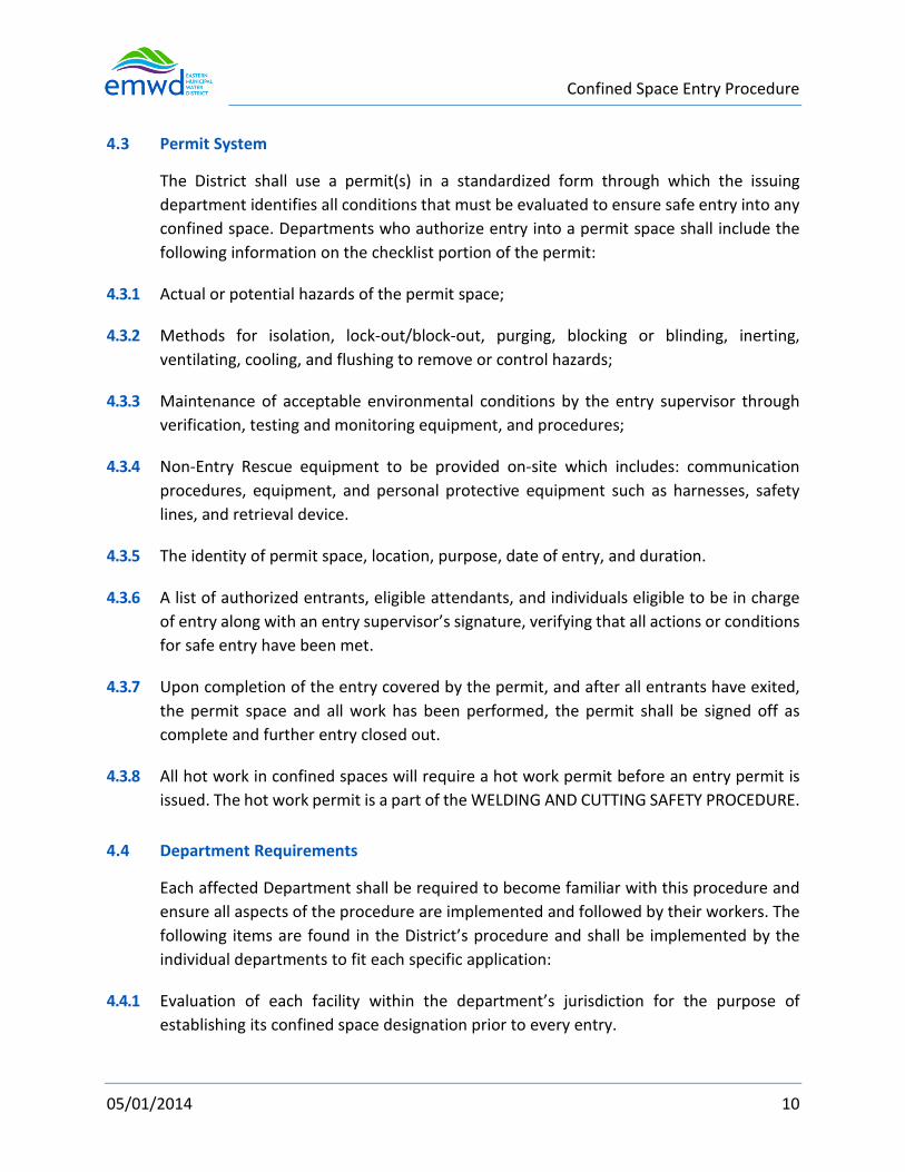
Confined Space Entry Procedure
05/01/2014 10
4.3 Permit System
The District shall use a permit(s) in a standardized form through which the issuing
department identifies all conditions that must be evaluated to ensure safe entry into any
confined space. Departments who authorize entry into a permit space shall include the
following information on the checklist portion of the permit:
4.3.1 Actual or potential hazards of the permit space;
4.3.2 Methods for isolation, lock-out/block-out, purging, blocking or blinding, inerting,
ventilating, cooling, and flushing to remove or control hazards;
4.3.3 Maintenance of acceptable environmental conditions by the entry supervisor through
verification, testing and monitoring equipment, and procedures;
4.3.4 Non-Entry Rescue equipment to be provided on-site which includes: communication
procedures, equipment, and personal protective equipment such as harnesses, safety
lines, and retrieval device.
4.3.5 The identity of permit space, location, purpose, date of entry, and duration.
4.3.6 A list of authorized entrants, eligible attendants, and individuals eligible to be in charge
of entry along with an entry supervisor’s signature, verifying that all actions or conditions
for safe entry have been met.
4.3.7 Upon completion of the entry covered by the permit, and after all entrants have exited,
the permit space and all work has been performed, the permit shall be signed off as
complete and further entry closed out.
4.3.8 All hot work in confined spaces will require a hot work permit before an entry permit is
issued. The hot work permit is a part of the WELDING AND CUTTING SAFETY PROCEDURE.
4.4 Department Requirements
Each affected Department shall be required to become familiar with this procedure and
ensure all aspects of the procedure are implemented and followed by their workers. The
following items are found in the District’s procedure and shall be implemented by the
individual departments to fit each specific application:
4.4.1 Evaluation of each facility within the department’s jurisdiction for the purpose of
establishing its confined space designation prior to every entry.
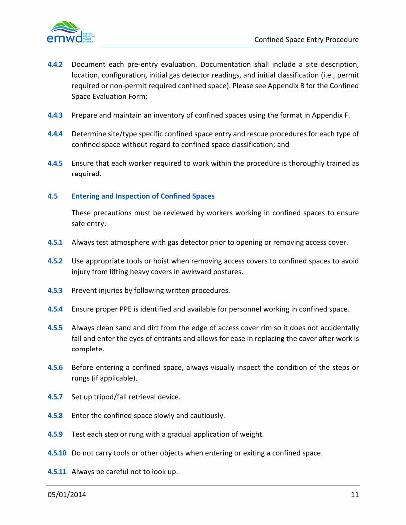
Confined Space Entry Procedure
05/01/2014 11
4.4.2 Document each pre-entry evaluation. Documentation shall include a site description,
location, configuration, initial gas detector readings, and initial classification (i.e., permit
required or non-permit required confined space). Please see Appendix B for the Confined
Space Evaluation Form;
4.4.3 Prepare and maintain an inventory of confined spaces using the format in Appendix F.
4.4.4 Determine site/type specific confined space entry and rescue procedures for each type of
confined space without regard to confined space classification; and
4.4.5 Ensure that each worker required to work within the procedure is thoroughly trained as
required.
4.5 Entering and Inspection of Confined Spaces
These precautions must be reviewed by workers working in confined spaces to ensure
safe entry:
4.5.1 Always test atmosphere with gas detector prior to opening or removing access cover.
4.5.2 Use appropriate tools or hoist when removing access covers to confined spaces to avoid
injury from lifting heavy covers in awkward postures.
4.5.3 Prevent injuries by following written procedures.
4.5.4 Ensure proper PPE is identified and available for personnel working in confined space.
4.5.5 Always clean sand and dirt from the edge of access cover rim so it does not accidentally
fall and enter the eyes of entrants and allows for ease in replacing the cover after work is
complete.
4.5.6 Before entering a confined space, always visually inspect the condition of the steps or
rungs (if applicable).
4.5.7 Set up tripod/fall retrieval device.
4.5.8 Enter the confined space slowly and cautiously.
4.5.9 Test each step or rung with a gradual application of weight.
4.5.10 Do not carry tools or other objects when entering or exiting a confined space.
4.5.11 Always be careful not to look up.

Confined Space Entry Procedure
05/01/2014 12
4.5.12 Never drop tools or supplies into a confined space. Pass by hand if possible, or tie object
to a hand line, or place in a bucket. Use half hitches to prevent objects from falling from
bucket.
4.5.13 Never clutter access area to prevent objects from falling, bouncing, being pushed, or
dragged into opening.
4.6 Contractors Entry Into Confined Spaces
When contractor workers (not under the District’s direct supervision) enter PRCS, ensure
the following:
4.6.1 Inform the contractor that the workplace contains confined spaces and that confined
space entry must be in compliance with EMWD Confined Space Entry Procedure as well
as that of the contractor.
4.6.2 Apprise the contractor of the characteristics of the confined space, including the known
hazards, access/egress, and any experiences with the space;
4.6.3 Coordinate entry operations with the contractor, when both District personnel and
contractor personnel will be working in or near a confined space (the contractor shall
have procedures for coordinating such entry operations, to prevent endangerment of the
workers of any other employer); and
4.6.4 Debrief the contractor at the conclusion of the entry operations regarding any hazards
confronted or created in the confined space during entry operations.
4.7 Recordkeeping
4.7.1 A written record must be made of the results of each atmospheric test performed. Utilize
the form in Appendix D.
4.7.2 If used, Confined Space Evaluation form (Appendix B) shall be kept at the site for the
duration of the work, and made accessible to entrants, attendants, supervisors, other
affected workers, and their representatives.
4.7.3 A copy of the Confined Space Entry Permit shall be posted or readily available at the job
site during confined space operations.
4.7.4 The above documentation must be kept on file by respective departments for a minimum
of three years.

Confined Space Entry Procedure
05/01/2014 13
4.8 Training
4.8.1 All workers involved in confined space operations (including entrants, attendants, and
confined space entry supervisors) must receive training in the appropriate procedures
and requirements described in this program. No person shall enter a confined space
unless trained and qualified to do so.
4.8.2 Supervisors shall also be trained in the following:
The possible toxic materials, lockout block out, flammable atmosphere conditions,
oxygen deficiencies or enrichment, and other actual or potential hazards in confined
spaces into which personnel must enter;
Be knowledgeable of the type of operations workers will be performing in a confined
space and of their impact on air quality, flammability, and/or availability of oxygen,
and ensure that workers take appropriate precautions;
Provide appropriate approved equipment; and
Ensure necessary forms are available to record the confined space activities; review
completed records; ensure the records are filed; and provide affected workers and/or
their representatives access to review them and record testing results.
4.9 Joint Use Facilities
Prior to entry by District personnel into confined spaces, such as manholes which may be
jointly owned or shared with another entity, the entry supervisor shall coordinate entry
operations with other affected users or owners so that workers or operations of one
employer do not endanger another employer’s personnel.
4.10 Entry Supervisor Review
NOTE: Entry Supervisors may contact Safety and Risk Management during the planning
phase of such operations to provide guidance on safe entry conditions, hazard control,
and personal protective equipment.
Before the start of work, the supervisor must:
4.10.1 Review the work assignment with workers, indicating any potential hazards involving the
confined space(s);
4.10.2 Describe the scope of work, equipment and materials needed, and any operating
instructions required to complete the job.

Confined Space Entry Procedure
05/01/2014 14
4.10.3 Identify any potential health risks and/or physical hazards or conditions, such as the
history of spills, fall hazard, the use of solvents, welding operations or flooding within the
work area, and methods to control those hazards;
4.10.4 Coordinate confined space entry activities with other employers, such as contractors or
sub-contractors so that no workers of any employer will be endangered during confined
space operations.
NOTE: Examples of methods to control hazards are lockout and blockout points, clearance
points, fall protection or ventilation.
4.11 Attendant/Entrant Review
An attendant and entrant is responsible for:
4.11.1 Understanding the nature of all actual or potential hazards that may be encountered
during entry into a confined space. If anything is not clearly understood, an
attendant/entrant shall ask questions;
4.11.2 Inspecting the safety equipment for confined space entry to ensure that it is in
operational condition;
4.11.3 Ensure that the atmospheric monitoring instruments (e.g., for oxygen, LEL, carbon
monoxide, hydrogen sulfide) are maintained in an operational status. Instruments shall
be tested and calibrated according to the manufacturer’s specifications or more
frequently. A daily bump test shall be performed against all gases or vapors for which an
instrument is configured
4.11.4 When the space is located such that work may encroach upon a public street or highway,
establish a safe work area by erecting barricades, cones, warning signs and wearing
appropriate reflective clothing;
4.11.5 The communication system between the Attendants and the facility, and between the
Attendants and the authorized Entrants must be checked prior to entry;
4.11.6 Energy sources (except for those necessary to perform the work at hand) that could
present a hazard to those in a confined space shall be locked out and blocked out in
accordance with the EMWD Lockout/Blockout Procedure.
4.11.7 The space shall be isolated and ventilated to prevent dangerous gases or chemical
substances from entering the confined space; and

Confined Space Entry Procedure
05/01/2014 15
4.11.8 All non-permit required, and permit-required confined spaces shall be considered to have
unacceptable atmospheres until proven safe by atmospheric testing. Ventilation must be
maintained at all times.
4.12 Atmospheric Testing
4.12.1 Prior to any confined space entry, the atmosphere shall be tested with an appropriate,
tested / calibrated direct reading instrument in accordance with the manufacturer’s
requirements, see Appendix G.
Testing for atmospheric hazards shall be in the following order:
Oxygen content;
Flammable gases & vapors; and
Potential toxic air contaminants.
4.12.2 Testing of Manholes and Other Spaces Prior to Opening
Prior to fully opening a confined space, insert the probe into an available opening and
draw a sample of the atmosphere into the meter, allowing sufficient time to obtain a
representative sample.
If the space opening has no hole, open the space only enough to insert a non-sparking
item, such as a piece of wood or brass, then insert the probe.
If atmospheric conditions are acceptable, then fully opening the confined space.
4.12.3 Test Atmosphere from Top to Bottom of Space:
Testing of the confirmed or potential confined spaces shall be conducted throughout
the entire portion of the space to be occupied. Some airborne contaminants may be
heavier or lighter than air and can collect at the bottom or top of spaces. It is required
that testing shall be done before ventilation and after the prescribed ventilation
period. Testing shall continue for the duration of the entry.
4.13 Sampling
4.13.1 For testing, insert the probe into the top of the confirmed, potential, or non-permit
confined space, and draw a sample of the atmosphere into the meter allowing sufficient
time to allow the meter to register and analyze. This may vary depending upon the type
of meter and length of sample tubing. Sample collection procedures shall follow the
manufacturer’s recommended procedure that is summarized in Appendix G

Confined Space Entry Procedure
05/01/2014 16
4.13.2 When monitoring for entries involving a descent into atmospheres which may be
stratified, the atmospheric envelope should be tested a distance of approximately four
(4) feet in the direction of travel and to each side.
4.13.3 If a sampling probe is used, the entrant’s rate of progress shall be slowed to accommodate
the sampling speed and detector response time.
4.14 Acceptable Atmosphere
If testing indicates an acceptable atmosphere, continuous ventilation is required prior to
and during any entry. Be sure to place the blower where fresh uncontaminated air is
drawn into the structure. The ventilation shall remain in operation during the complete
entry.
4.15 Unacceptable Atmosphere
If after any needed ventilation, testing continues to indicate atmospheric contaminants
outside of acceptable entry levels, the space shall not be entered. Refer to Permit
Required Confined Space Entry Procedure section for additional information.
4.16 Guarding The Opening
When covers are removed, a railing, temporary cover, or temporary barrier that will
prevent an accidental fall through the opening and protect each worker working in the
space from foreign objects entering the space shall guard the opening.
5 Entry Instructions
5.1 When operations are to be conducted which may impact air quality (such as welding,
spray coating, abrasive blasting, or use of chemicals), additional precautions are to be
taken. Consideration shall be given to safe entry conditions, hazard control and personal
protective equipment during the planning phase of such operations.
5.2 Prior to any entry into a PRCS, the Entry Supervisor shall assure that all provisions of a
Confined Space Permit (Appendix C) have been completed and the following specific
provisions have been met:
5.2.1 Supervisor Review of Hazards
5.2.2 Equipment Inspection
Confined Space Entry Procedure
05/01/2014 17
5.2.3 Instrument Bump Test and Calibration
5.2.4 Work Area Preparation
5.2.5 Lockout and Isolation
5.2.6 Atmospheric Testing
5.2.7 Ventilation
5.2.8 Check “List of Requirements for Entry, Working In, and Exiting Confined Space” (Appendix
A)
NOTE: The supervisor of the workers may be the Entry Supervisor, or the responsibility of
the Entry Supervisor may be delegated.
5.2.9 Assemble and test the retrieval equipment before entry into a PRCS.
5.2.10 The Entry Supervisor is to check that the appropriate entries have been made on the
Permit, that the Permit specified tests have been conducted, and that the specified
procedures and equipment are in place before endorsing the Permit and allowing entry
to begin.
5.2.11 When the Permit is signed, the authorized entrant(s) may enter the PRCS.
NOTE: Following the information specified in the Entry Permit, the Attendant
continuously maintains an accurate count of authorized entrants in the confined space.
5.2.12 If the PRCS poses no actual or potential atmospheric hazards, and if all serious safety and
health hazards within the space are eliminated without entry into the space, the Permit
Required Confined Space (PRCS) may be re-classified as a Non-Permit Confined Space
(NPCS) for as long as the hazards remain eliminated. Reclassification of a space requires
use of the evaluation form in *Appendix B. Ventilation is still required.
NOTE: Control of atmospheric hazards through forced air ventilation does not constitute
elimination of the hazards. For example, carbon monoxide may still be generated in a
space while being controlled by ventilation.
5.2.13 The Entry Supervisor shall document the basis for determining that all hazards in a permit
space have been eliminated, through a certification on the permit that contains the date,
the location of the space, and the signature of the person making the determination. The
permit will then remain posted for the duration of the entry.

Confined Space Entry Procedure
05/01/2014 18
5.2.14 If hazards arise within a PRCS that has been reclassified as an NPCS, each worker in the
space shall exit the space. The Entry Supervisor shall then reclassify the entry as a PRCS
and a new permit shall be initiated.
6 Duties and Responsibilities
6.1 Authorized Entrants
The authorized entrants are required to:
6.1.1 Understand the hazards that may be encountered during entry, including information on
the mode, signs or symptoms, and consequences of exposure. Know methods of hazard
mitigation
6.1.2 Properly inspect and use equipment as required by the permit.
6.1.3 Follow responsibilities identified in entry instructions.
6.1.4 Maintain communications with the Attendant.
6.1.5 Alert the Attendant whenever:
The entrant recognizes any warning sign or symptom of exposure; or
A prohibited condition is detected.
6.1.6 Exit the permit space whenever:
An order to evacuate is given by the Attendant;
There is a warning sign or symptom of exposure;
A prohibited condition is detected; or
An alarm is activated.
6.2 Attendants
The Attendants are required to:
6.2.1 Know the hazards that may be faced during entry, including information on the mode,
signs or symptoms, and consequences of the exposure.
6.2.2 Be aware of possible behavioral effects of hazard exposure on authorized entrants.
Confined Space Entry Procedure
05/01/2014 19
6.2.3 Continuously maintain an accurate count of authorized entrants in the permit space and
ensure that the permit accurately identifies who is in the permit space.
6.2.4 Remain immediately outside the permit space during entry operations until relieved by
another attendant.
6.2.5 Communicate with authorized entrants as necessary to monitor entrant status and alert
entrants of the need to evacuate the space.
6.2.6 Monitor activities inside and outside the space to determine if it is safe for entrants to
remain in the space and order the authorized entrants to evacuate the permit space
immediately under any of the following conditions:
If the Attendant detects a prohibited condition;
If the Attendant detects the behavioral effects of hazard exposure in an authorized
entrant;
If the Attendant detects a situation outside the space that could endanger the
authorized entrants; or
If the Attendant cannot effectively and safely perform all the duties required under
the permit.
6.2.7 Summon rescue and other emergency services as soon as the Attendant determines that
authorized entrants may need egress assistance from permit spaces.
Perform non-entry rescues as determined during pre-job planning; and
Perform no duties that might interfere with the Attendant’s primary duty to monitor
and protect the authorized entrants.
6.3 Entry Supervisors
The Entry Supervisors are required to:
6.3.1 Understand the hazards that may be faced during entry, including information on the
mode, signs or symptoms, and consequences of exposure to hazardous conditions,
materials or atmospheres;
6.3.2 Determine when to terminate the entry and cancel the permit;
6.3.3 Determine, whenever responsibility for a permit space entry operation is transferred and
at intervals dictated by the hazards and operations performed within the space, that entry

Confined Space Entry Procedure
05/01/2014 20
operations remain consistent with terms of the entry permit and that acceptable entry
conditions are maintained;
6.3.4 Verify, by checking that the appropriate entries have been made on the permit, that all
tests specified by the permit have been conducted and that all procedures and equipment
specified by the permit are in place before endorsing the permit and allowing entry to
begin;
6.3.5 Verify for high hazard confined space entries that rescue services—other than self-rescue
or non-entry rescue—are available and that the means for summoning them are
operable; and
6.3.6 Remove unauthorized individuals who enter or who attempt to enter the permit space
during entry operations.
6.4 Rescue Duties
Departments are responsible to ensure that these procedures are followed when workers
are working in a confined space:
6.4.1 Recognition of actual or potential emergencies;
6.4.2 Notification of EMS and/or Central Control/IOC of rescues;
6.4.3 Request for additional workers if needed. NOTE: Workers may come from any
department;
6.4.4 Proper use of safety equipment;
6.4.5 Required First Aid/CPR training; and
6.4.6 Non-Entry Rescue Methods.
6.4.7 High hazard permit required confined space entries may require the use of a standby
rescue team at the site. Contact Safety, Risk and Emergency Management for all high
hazard entries.
7 Ventilation Requirements
Ventilation is one of the most important rules of safety concerning confined space entry.
Though ventilation can provide good quality make up air, it cannot reduce other hazards

Confined Space Entry Procedure
05/01/2014 21
that are associated with permit space(s). The ventilation requirements that must be met
prior to entry are as follows:
7.1 Pre-Entry Requirements
7.1.1 Various sizes of permit spaces are located through the District. When initial air sampling
determines a hazardous atmosphere is present, forced air ventilation shall be performed
until the hazard within the space has been eliminated. A continuous supply of fresh air
shall be provided while entrant(s) is/are in the confined space. The confined space must
have ten (10) complete air changes before sampling the air inside the confined space
again.
To determine how long it will take to achieve ten (10) complete air changes in the
confined space, the following information must be known:
The cubic feet of space inside the confined space; and
The cubic feet per minute (CFM) the ventilator is rated for.
NOTE: Multiple bends in the ventilation hose will reduce the actual CFM capacity of the
ventilating blower (each 90º bend reduces the rated CFM capacity of a ventilation blower
by up to 50%).
To determine the cubic feet of space inside the confined space for square or rectangular
spaces:
Multiply the Length x Width x Height. EXAMPLE: A confined space is 20’ x 15’ x 30’.
20’ x 15’ x 30’ = 9,000 cubic feet
The rating of the ventilator shows the cubic feet of air the blower will discharge.
For this example, let’s assume the ventilator has a rating of 1,500 CFM.
To find out how long it will take to make one complete air change inside the
confined space, divide 9,000 cubic feet by 1,500 CFM. The answer is 6. Therefore,
it will take 6 minutes to make one complete air change inside the confined space.
Ten (10) air changes are required. Multiply 6 minutes by 10, the required number
of air changes in the confined space:
10 x 6 = 60. It will take 60 minutes to achieve 10 complete air changes.

Confined Space Entry Procedure
05/01/2014 22
If the confined space is round, multiply π (3.14) times the radius squared, times the length
of the cylinder (pipe, tunnel, etc.) = cubic feet of space. 𝜋r2h=volume
EXAMPLE: 𝜋 (3.14) x radius2 x length of cylinder or height of tank (pipe, tunnel,
etc.) = cubic feet of space. Assume a pipe has a 3’ diameter and is 30’ long. One-
half of the 3’ diameter is 1.5 feet (the radius). 1.52 (1.5 x 1.5) = 2.25 square feet.
To simplify: 3.14 x 2.25 = 7.07 square feet. (The actual number is 7.0686, but we
rounded up.)
7.07 square feet x 30’ (the length of the cylinder) = 212 cubic feet.
To find out how long it will take to make one complete air change inside the
confined space, divide 212 cubic feet by 1,500 cfm. The answer is, 0.14 minutes
for one complete air change.
Ten (10) complete air changes are required. Therefore, 10 x 0.14 minutes per air
change = 1.4 minutes.
Round up and let the ventilator push fresh air into the confined space for 2
minutes before testing the atmosphere inside the confined space again.
To achieve a greater efficiency of air exchanges, when it is possible, move the end
of the hose around by using a rope. Pull the end to the hose up into the upper
corners of the confined space. Also move the end of the hose around near the
bottom of the confined space to move the gases or air around so it will be diluted
or exhausted out of the confined space.
After 10 complete (or near complete) air changes have been made, lower the hose
on the air monitor into the confined space and sample the air at different levels.
The end of the air monitor hose shall be lowered 2 to 4 feet each time to sample
the air at different levels inside the confined space.
A continuous supply of fresh air shall be provided while entrant(s) is/are in the
confined space.
7.2 Work in Progress
7.2.1 A continuous supply of fresh air shall be provided while entrant(s) is/are in the confined
space.
7.2.2 Entrant must exit confined space if blower stops.

Confined Space Entry Procedure
05/01/2014 23
7.2.3 All blowers shall be at a minimum of 1,500 cfm.
7.2.4 Five (5) air exchanges per hour for a permit space are suggested.
7.3 Recordkeeping
The Entry Supervisor shall document the time that the blower was started and when the
blower was shut-off on the permit.
8 Safety Equipment
No worker shall perform or order to be performed, any work in a permit space unless all the
necessary safety equipment is available and all proper safety procedures are followed.
Requirements for safety equipment and use are as follows:
8.1 Fall / Retrieval Device and Approved Support Device
A fall/retrieval device and tripod or other adequate anchorage shall be required for all
top-opening entries into a permit space.
8.1.1 Tripod
The tripod shall be capable of set-up on surfaces that are not level.
The tripod shall be capable of locking in place with safety chains attached to base of
legs.
Non-slip feet on legs of tripod.
It is recommended that tripods are adjustable up to 9 feet tall.
8.1.2 Other anchorage points used shall be capable of supporting a 5000 pound static load and
the means of attachment shall be rated for fall protection and retrieval hoist loads.
8.1.3 Fall/Retrieval Device
Fall/retrieval device may have a “fall-arrest” capability.
Additional block to tackle hoist may be added for retrieval purposes.
Self-Retracting Lifelines (SRL) shall be the required fall protection device used in
conjunction with permit required confined space entry. Certain spaces may require
the use of a winch type retrieval device as a primary means of extraction with an SRL
as a secondary means of retrieval.

Confined Space Entry Procedure
05/01/2014 24
8.2 Personal Protective Equipment
8.2.1 A hard hat shall be worn at all times in a confined space.
8.2.2 To provide as much body protection as possible, coverall or uniforms shall be worn when
working in a confined space.
8.2.3 Special safety equipment such as boots, waders, dry suit, gloves, safety goggles/glasses
and ear protection shall be worn as needed.
8.2.4 A fall/retrieval device or other approved devices shall be provided for lifting worker(s) out
of top opening confined spaces.
8.2.5 Rescue lifelines or wristlets may be utilized in certain permit required confined spaces
where the use of a fall retrieval device is not possible.
8.2.6 A full body harness will be required with this program. This harness must meet ANSI
Standard A10.14 and EMWD Fall Protection Procedure guidelines.
8.2.7 Intrinsically safe electrical equipment is required for confined spaces.
8.2.8 Respiratory protection equipment will be required as necessary based on an evaluation
of potential contaminants in the space.
8.3 Equipment Inspection
8.3.1 All equipment needed for working in a permit space shall be periodically inspected and
repaired or replaced if necessary. It must also be inspected prior to each entry into a
confined space by both the Entry Supervisor and the Entrant(s).
8.3.2 If a necessary piece of equipment is in questionable condition, work shall halt until the
equipment is repaired or replaced.
8.3.3 Manufacturer recommendations shall be followed for all equipment.
9 Permit Classification System
The “permit classification system” is based on existing or potential hazards relative to the
confined space. The classification is based upon the characteristics and configuration of
the space, oxygen level, flammability, and toxicity. The classification shall be determined

Confined Space Entry Procedure
05/01/2014 25
by the most hazardous condition of entering, working in, and exiting a confined space.
Refer to checklist of requirements for entry.
9.1 Permit Required Confined Space
Permit Required Confined Space (PRCS) is one that presents a situation that may be
immediately dangerous to life or health (IDLH) or may cause serious injury or illness to an
entrant.
9.1.1 These include, but are not limited to, oxygen deficiency, explosive or flammable
atmospheres, physical hazards, and/or concentrations of toxic substances.
9.1.2 Special requirements for PRCS are as follows:
Two (2) Attendants required outside PRCS at all times. The Entry Supervisor may act
as the second attendant.
One (1) Attendant must maintain communication with entrant at all times (i.e., at
manhole, hatch, opening, etc.);
Second Attendant must remain onsite in the area of the permit required confined
space entry; and
Entrant shall utilize approved safety harness and lifeline/retrieval device.
Common types of PRCS are sewer manholes, sewer lines, Lift Station wells, junction
structures, valve vaults, meter vaults, pumping plant wet wells, vats, pits, large pipe and
ducts, and various types of storage tanks. Situations may arise that make Non-Permit
Confined Space (NPCS) a PRCS.
9.2 Non-Permit Required Confined Space
A Non-Permit Required Confined Space (low hazard) is one in which the potential hazard
would not require any special modification of the work procedure except for the
following:
9.2.1 If no Attendant is used, Central Control will be notified of location, entry time, estimated
working time, and interval for safety checks. They will also be notified when work is
completed.
9.2.2 Entrant will have constant and reliable communications with Central Control (via hand-
held radio).
9.2.3 Entrant will have safe, a stable means of entry and exit (ladder, etc.).
Confined Space Entry Procedure
05/01/2014 26
9.2.4 Atmospheric testing, monitoring and ventilation are required.
9.3 Special Consideration Spaces
9.3.1 Any below grade facility or area with restricted access (i.e., ladder access, entry
configuration hazard) that is ventilated full time, has the potential to become a confined
space and shall be entered after a worksite hazard analysis has been conducted. These
sites shall be treated as confined spaces until the hazard has been removed or mitigated
via a JSA conducted by a qualified person.
9.3.2 Trenches and other earthworks are normally not considered confined spaces. Situations
can arise, however, which would make these structures confined spaces. A broken gas
main, force main or sewer main may need to be classified as a confined space if a
determination has been made that atmospheric hazards are present.
9.3.3 Any confined space that cannot be entered according to the strict provisions and
requirements of this procedure can only be entered once a site-specific written
procedure has been developed. This procedure shall include the development of a JSA
and must identify all hazards and the alternative measures of personal protection that
will be utilized to protect the entrants in the confined space. The written procedure
must be reviewed and approved by the Safety, Risk and Emergency Management
Department prior to entry operations.
9.3.4 All sewer manholes within the District’s boundaries shall be considered permit required
confined spaces and entered based off an evaluation of all hazards present.
Facilities with an engineered means of ingress/egress (stairwell into lower levels, entry
points that would allow self-rescue) which may be ventilated full time are to be
considered workplaces with the potential for a hazardous atmosphere. Examples of these
sites would be sewer lift station drywells and wet wells with engineered stairwells and
influent pump station/head works buildings with multiple entry/exit points. These
facilities shall not be considered confined spaces, but shall be evaluated for worker
exposures through a worksite hazard analysis (JSA, SOP) conducted by the department
seeking access.
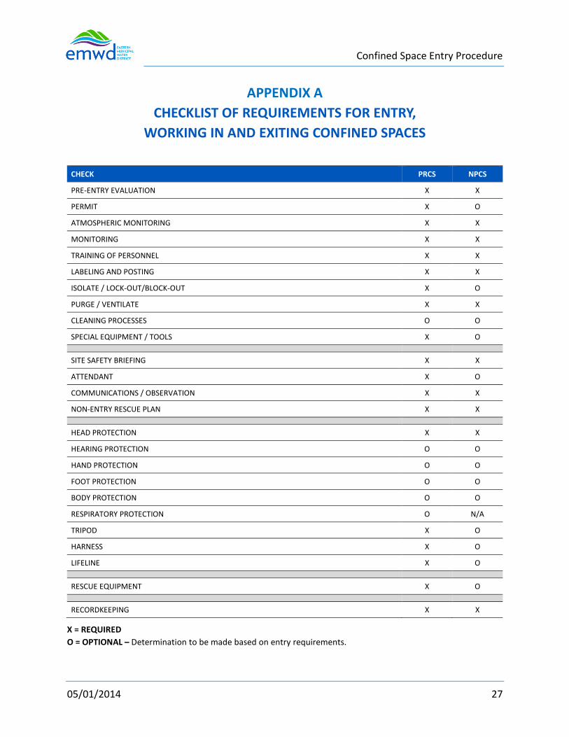
Confined Space Entry Procedure
05/01/2014 27
APPENDIX A
CHECKLIST OF REQUIREMENTS FOR ENTRY,
WORKING IN AND EXITING CONFINED SPACES
CHECK PRCS NPCS
PRE-ENTRY EVALUATION X X
PERMIT X O
ATMOSPHERIC MONITORING X X
MONITORING X X
TRAINING OF PERSONNEL X X
LABELING AND POSTING X X
ISOLATE / LOCK-OUT/BLOCK-OUT X O
PURGE / VENTILATE X X
CLEANING PROCESSES O O
SPECIAL EQUIPMENT / TOOLS X O
SITE SAFETY BRIEFING X X
ATTENDANT X O
COMMUNICATIONS / OBSERVATION X X
NON-ENTRY RESCUE PLAN X X
HEAD PROTECTION X X
HEARING PROTECTION O O
HAND PROTECTION O O
FOOT PROTECTION O O
BODY PROTECTION O O
RESPIRATORY PROTECTION O N/A
TRIPOD X O
HARNESS X O
LIFELINE X O
RESCUE EQUIPMENT X O
RECORDKEEPING X X
X = REQUIRED
O = OPTIONAL – Determination to be made based on entry requirements.

Confined Space Entry Procedure
05/01/2014 28
CONFINED SPACE ENTRY PERMIT DECISION DIAGRAM

Confined Space Entry Procedure
05/01/2014 29
APPENDIX B CONFINED SPACE EVALUATION FORM

Confined Space Entry Procedure
05/01/2014 30
APPENDIX B
CONFINED SPACE PERMIT

Confined Space Entry Procedure
05/01/2014 31
APPENDIX C
RECORD OF GAS ANALYSIS
Location Date
Gas Read Time (15 Min. Increments)
Worker Taking Read O2 Lel H2s Co
Entrant(S) Name And Employee Number
Time In
Time Out

Confined Space Entry Procedure
05/01/2014 32
APPENDIX D
RIVERSIDE COUNTY FIRE DEPARTMENT FACILITIES WITH CONFINED
SPACE RESCUE EQUIPMENT AND TRAINING
Station #2 – Moreno Valley 24935 Hemlock Moreno Valley CA, 92557 (951) 242-3101 Hazardous Materials Station
Station #34 – Winchester
32655 Haddock Street Winchester, CA 92596
(951) 926-6430
Station #73 – Rancho California
27415 Enterprise Circle West
Temecula, CA 92590
(951) 699-0351
Station #76 – Menifee Lakes
29950 Menifee Road
Menifee, CA 92584
(951) 679-2241
Station #97 – Rosetta Canyon
41725 Rosetta Canyon Drive
Lake Elsinore, CA 92530
(951) 245-0420

Confined Space Entry Procedure
05/01/2014 33
APPENDIX E
CONFINED SPACE INVENTORY AND LABELING
Inventory
Each department having responsibilities over a District facility shall develop and maintain a
confined space inventory that includes at least the information shown in the table below. Area
refers to the general unit or section of a plant or facility. Location is the specific place where the
confined spaces entry point is located. It may be designated on a map, using Maximo asset
numbers, P&ID reference numbers, name of equipment, or any other specific method.
Description is the type of opening such as manway, manhole, duct, ladder, hatchway, tank top,
etc.
The hazards of each space shall be described by as many of the Hazard Code designations as exist
and/or for which there is a potential to exist in the confined space. The confined space evaluation
form (Appendix B) shall be used as reference and/or this inventory used to aid in filling the
evaluation form in Appendix B. Hazard code 4 has several categories which shall be used as 4a,
4b, 4c, etc.
The Special Considerations column may be used as needed for notes or to describe issues related
to the space, its entry or hazards.
To be included in the inventory:
Tanks, sewers, basins, pits, electrical vaults, piping/valve vaults, large diameter pipe or duct, vats,
vessels, silos, storage bins, hoppers, and ladder entry into pumping plants or subgrade facilities
or other spaces that may have limited means of entry,
# AREA LOCATION DESCRIPTION HAZARD CODE SPECIAL CONSIDERATIONS
1 East of Chlorine Contact
West of Fence Line Manhole - Drain 1, 2, & 4c,b
2 Contact Basin Contact Basin Contact Basin # 3 1, 2, & 4c,b
3 Contact Basin Contact Basin Contact Basin # 2 1, 2, & 4c,b
Hazard Codes
1 Contains or has the potential to contain a hazardous atmosphere—toxic or oxygen <19.5%
or > 23.5%.

Confined Space Entry Procedure
05/01/2014 34
2 Contains a material that has the potential for engulfing an entrant including cave-in of
excavations.
3 Has an internal configuration such that an entrant could be trapped or asphyxiated by
inwardly converging walls or by a floor that slopes downward and tapers to a smaller cross-
section.
4 Contains any other recognized serious safety or health hazard.
a Electrical
b Moving parts
c Surface chemical
d Hot temperature or hot surface
e Biological hazard (including microbiological, insect, or animal)
Labeling and Signage
Confined spaces shall be labeled to provide a reasonable warning for workers to keep out unless they have a permit. A sign reading “DANGER -- PERMIT-REQUIRED CONFINED SPACE, DO NOT ENTER” and using an additional sign with similar language when appropriate would satisfy the requirement for a sign. In areas such as aeration basins where confined spaces exist in sub-walking surface in a large area, perimeter signs may be used as well as designated access point such as hatchways or ladder swing gates. Perimeter sign wording shall be considered for each area and shall describe the access point of confined space entry. Example: “All basins below pedestrian grating are considered confined spaces—DO NOT ENTER.” Signs shall be legible and maintained to address weathering or work environments that cause deterioration. Signs shall be placed so they remain visible while confined space operations are under way. Sign placement on the entry doors, covers or hatchways shall be avoided since they would no longer be visible when the doors, covers or hatchways are removed during confined space operations.

Confined Space Entry Procedure
05/01/2014 35
APPENDIX F
GAS DETECTOR (MONITOR) MANUFACTURER’S REQUIREMENTS
Industrial Scientific
Ventis MX4
Zero, Calibration, and, Bump testing
Gas detection instruments are potentially life-saving devices. When completed regularly, the
procedures defined below help to maintain proper instrument functionality and enhance
operator safety.
Procedures
Configuration – The configuration process allows qualified personnel to review and adjust a
unit’s settings.
Bump Test – (or “functional test”). Bump testing checks for sensor and alarm functionality. The
installed sensors are briefly exposed to expected concentrations of calibration gases that are
greater than the sensors’ low alarm set points. When one or more sensors “pass” the test, they
are “functional” and the unit will alarm. Each sensor’s “pass” or “fail” result is indicated on the
unit’s display.
Note: a bump test does not measure for sensor accuracy (see “Calibration”).
Zero – Zeroing sets each installed sensor to recognize the ambient air as clean air. If the ambient
air is not truly clean air, any gasses that are present and relevant to the installed sensor types will
be measured and displayed as zero. Readings will be inaccurate until the unit is correctly zeroed
in truly fresh air or with a zero-air cylinder.
Calibration – All sensors gradually degrade over time. This diminishes a sensor’s ability to
measure gas concentrations accurately; however, regular calibrations adjust the instrument to
compensate for this decline in sensitivity. During calibration, the installed sensors are exposed to
expected concentrations of calibration gases and, when needed, the instrument will self-adjust
to ensure the accurate measurement and display of gas concentration values.
Note: When a sensor has degraded beyond an acceptable level, no further adjustment is possible
and the sensor will no longer pass calibration.
Peak Readings – The instrument stores the highest detected gas readings, the “peak readings”
or “peaks”. Bump testing and calibration will often register new peak readings. Therefore, the
clearing of the peak readings should follow each calibration. The instrument operator may also

Confined Space Entry Procedure
05/01/2014 36
wish to clear the peak readings after a bump test, before a change in location, or after an alarm
is addressed and cleared.
Note: The peak readings and the data log readings are stored independently of one another;
therefore, clearing the peak reading does not affect the data log. Powering the instrument off or
changing its battery does not affect the peak reading. These checks and balances help promote
operator safety, and serve to contain the peak readings in a “black-box” manner. In the event of
a gas- related incident, this black-box record can be useful to the safety team or a prospective
investigator.
Recommendations
Industrial Scientific Corporation (ISC) minimum frequency recommendations for each procedure
are summarized in the table below. These recommendations are based on field data, safe work
procedures, industry best practices, and regulatory standards to help ensure worker safety.
Industrial Scientific is not responsible for setting safety practices and policies. These policies may
be affected by the directives and recommendations of regulatory groups, environmental
conditions, operating conditions, instrument use patterns and exposure to gas, and other factors.
Procedure ISC Recommended minimum frequency
Configuration Before first use and as needed thereafter.
Calibration Before first use and monthly thereafter.
Bump test Prior to each day’s use.
Between regular calibrations, ISC also recommends a calibration be performed immediately
following each of these incidences: the unit falls, is dropped, or experiences another significant
impact; is exposed to water; fails a bump test; or has been repeatedly
Remote Sampling
Aspirated monitor
In confined space, an air sample should be taken in four-foot (1.22 m) intervals.
Guidelines for using a motorized pump and sampling line
When sampling with a motorized pump and sampling line, Industrial Scientific recommends the
following:
Choose the tubing type based on the target gases. If the target gases are known, use Teflon-
lined tubing when sampling for these gases: chlorine (Cl2), chlorine dioxide (ClO2), hydrogen
chloride (HCl), and volatile organic compounds (VOCs). For other known target gases,
urethane tubing or Teflon-lined tubing may be used.

Confined Space Entry Procedure
05/01/2014 37
When the target gases are unknown, use Teflon-lined tubing.
Know the length of the sample line as it is a factor in determining sampling time. A sample
line may consist of tubing, a probe, or a probe and tubing. It should also have a dust filter–
water stop installed at the line’s end that will extend into the sample area. Sample-line length
is defined as the distance from the dust filter–water stop will extend into the sample area.
Sample-line length is defined as the distance from the dust filter–water stop opening to the
point where the line connects to the pump’s inlet. Ensure sample-line length does not exceed
the pump’s maximum draw.
Before and after each air sample, perform a test of the full sampling line.
Use a thumb to block the end of the sampling line at the water-stop opening. This should
cause a pump-fault alarm.
Remove the thumb from the water-stop opening. After the alarm cycle completes, the pump
should resume normal operation.
Note: If a pump fault does not occur, check and correct for cracks or other damage, debris, and
proper installation in these areas: all sampling line connections, the pump’s inlet cap and inlet
barrel, and the dust filter- water stop items at the end of the sampling line and inside the pump
inlet barrel.
Based on sample-line length, calculate the minimum time recommended for the air sample
to reach the instrument’s sensors. As shown below, use a base time of 2 minutes, and add 2
seconds for each 30 cm (1 ‘) of line length. Watch the display screen for gas readings and, if
present, allow them to stabilize to determine the reading.
Minimum sample time for common sample-line lengths
Sample-line length Base time (minutes) + Sample-line-length factor (seconds) = Minimum sample time (mm:ss)
3.05 m (10 ‘)
6.10 m (20 ‘)
2 min
2 min
+
+
(10 x 2 s)
(20 x 2 s)
=
=
02:20
02:40
9.14 m (30 ‘) 2 min + (30 x 2 s) = 03:00
12.10 m (40 ‘) 2 min + (40 x 2 s) = 03:20
15.24 m (50 ‘) 2 min + (50 x 2 s) = 03:40
18.29 m (60 ‘) 2 min + (60 x 2 s) = 04:00
21.34 m (70 ‘) 2 min + (70 x 2 s) = 04:20
24.38 m (80 ‘) 2 min + (80 x 2 s) = 04:40
27.43 m (90 ‘) 2 min + (90 x 2 s) = 05:00
30.48 m (100 ‘) 2 min + (100 x 2 s) = 05:20

[PAGE LEFT INTENTIONALLY BLANK]

Rev:10/23/14
SPECIFICATIONS - DETAILED PROVISIONS
Section 01026 - Schedule of Values
TABLE OF C O N T E N T S
PART 1 - GENERAL ............................................................................................................................. 1 1.01 SUMMARY ................................................................................................................................. 1 1.02 PREPARATION ........................................................................................................................... 1 1.03 SUBMITTAL ................................................................................................................................ 1
PART 2 - EXECUTION ......................................................................................................................... 2 2.01 SAMPLE SCHEDULE OF VALUES ................................................................................................ 2

[PAGE LEFT INTENTIONALLY BLANK]
Schedule of Values 01026-1
SECTION 01026
SCHEDULE OF VALUES
PART 1 - GENERAL
1.01 SUMMARY
A. Section Includes: Preparation, format, and submittal of Schedule of Values.
B. The Schedule of Values will establish unit prices for individual items of work.
C. The Schedule of Values will be the basis for payment of contract work and will be used to establish payment for any “extra work” i.e., work requested which is beyond the scope of the original contract.
1.02 PREPARATION
A. Prepare satisfactory Schedule of Values identifying costs of items of work shown in sample included at the end of the Section.
Assign unit prices to items of work and calculate total prices, which aggregate the Contract Price. Base unit prices on costs associated with scheduled activities for each item of work. For any bid item broken down into unit prices, Contractor shall verify that the unit cost of the items does not extend beyond two decimal places and that the unit cost when multiplied by the unit quantity equals the exact bid item value with no remainder.
1.03 SUBMITTAL
A. Submit preliminary Schedule of Values at the preconstruction meeting to the District for review and approval. DO NOT SUBMIT THE SCHEDULE OF VALUES WITH YOUR BID PACKAGE.
B. Submit corrected Schedule of Values within ten (10) days upon receipt of reviewed or rejected Schedule of Values for approval by the District.
C. Upon request, support prices with data which will substantiate their correctness.

Schedule of Values 01026-2
PART 2 - EXECUTION
2.01 SAMPLE SCHEDULE OF VALUES The following is a sample and acceptable form for Schedule of Values. The District may request additional detail as necessary to adequately represent the Scope of Work. The contractor may provide an additional breakdown of any of the items listed below. THE CONTRACTOR SHALL VERIFY ALL QUANTITIES AND ITEMS OF WORK PRIOR TO SUBMITTAL.
SCHEDULE OF VALUES
Item No. Qty Unit Description Unit Cost Total Cost
1 1 LS Mobilization and Approved: Bonds, Insurance, Schedule of Values, and Project Control Schedule.
Preset $52,000
2 1 LS Furnish and Install temporary power, including a temporary portable MCC with (2) 100 HP VFDs, portable generator, MCP-1 panel, antenna and appurtenances.
Lump Sum
3 1 LS Remove and dispose of all equipment designated for demolition.
Lump Sum
4 1 LS Furnish and Install 800 Amp SCE Service Switchboard with SCE Meter socket. Work also includes coordination with SCE for installation of secondary conductors, CTs and meter.
Lump Sum
5 1 LS Furnish and Install 800 Amp Distribution Switchboard and automatic transfer switch.
Lump Sum
6 1 LS Furnish and Install four (4) VFDS [(1)-125 HP, (2)-100HP, (1)-75HP], each in a NEMA 1A enclosure including A/C units.
Lump Sum
7 1 LS Furnish and Install control panel, including installation of EMWD supplied RTU, OIT, backplane, and appurtenances.
Lump Sum
8 1 LS Construct new motor for Pump# 4 matching existing motor.
Lump Sum

Schedule of Values 01026-3
Item No. Qty Unit Description Unit Cost Total Cost
9 1 LS Furnish and install all electrical cable trays, conduit, conductors, cables, grounding systems, junction boxes, conduit supports, and appurtenances. The power and control cables shall be XHHW-2 type conductors, 90 deg C.
Lump Sum
10 1 LS Furnish and install emergency standby generator, foundation, housekeeping pad and appurtenances.
Lump Sum
11 1 LS Construct miscellaneous site concrete, retaining wall, chain-link fencing, and access gates.
Lump Sum
12 1 LS Perform field testing and commissioning of equipment
Lump Sum
13 1 LS Provide Operation and Maintenance Manuals
Lump Sum
14 1 LS Demobilization and cleanup Lump Sum
TOTAL (MUST EQUAL BID AMOUNT)
DO NOT SUBMIT THE SCHEDULE OF VALUES
WITH YOUR PROPOSAL PACKAGE
END OF SECTION 01026

Schedule of Values 01026-4
[PAGE LEFT INTENTIONALLY BLANK]

Work Restrictions and Sequence of Work Section 01185 – 1
SECTION 01185
WORK RESTRICTIONS AND SEQUENCE OF WORK
PART 1 - GENERAL
1.01 GENERAL CONSTRAINTS ON SEQUENCE AND SCHEDULING OF WORK
A. Contractor shall conduct work in a manner to limit the shutdown duration of the booster pumps.
B. Pump shutdowns shall be coordinated and performed in accordance with the requirements specified in Shutdown Coordination Table (Contract Documents Appendix D).
C. District will provide an RTU and antenna element for temporary use during construction to automate facility. Contractor will be required to install the temporary RTU, with the same installation requirements for the permanent RTU (as applicable). The District shall program and integrate the temporary RTU with SCADA system within the estimated 3-day shutdown shown in Item No. 1 of the Shutdown Coordination Table.
D. Contractor shall provide 24/7 power to temporary RTU and Pump 1 and Pump
4. E. The general arrangement of the temporary power and control equipment
required to operate of the facility throughout the construction phase, as specified herein and Appendix D, is shown on Sheet G-3 of the Contract Drawings. Should the Contractor wish to stage temporary facilities differently, the Contractor shall submit proposed configuration and obtain prior approval from the District.
F. The Contractor shall be responsible for installing the temporary RTU provided
by the District, and furnishing and installing temporary standby generator, wiring, antenna equipment, instrumentation signal splitters, and all other appurtenances required for a fully independent and automated temporary power and control system for pumps P-1 and P-4 during the shutdown of the primary/stationary electrical and control equipment (Item 1 of the Shutdown Coordination Table).

Work Restrictions and Sequence of Work Section 01185 – 2
G. Contractor shall include costs in his bid price for compliance with the specific sequencing limitations and all the constraints, temporary facilities, and the related general factors pertaining to maintaining the operational requirements of the Redlands and Cottonwood Booster Requirements as specified herein and the Shutdown Coordination Table.
H. Contractor shall provide safe, continuous access to existing Redlands and
Cottonwood Booster facilities for District's staff. Isolation of individual equipment items or pipe segments may require equipment stoppage and/or valve closures. All equipment and valves shall be operated by District staff. Contractor shall not operate any existing equipment or valves.
I. Contractor shall provide layout of the temporary power plan. J. Contractor shall provide copies of the permits for the temporary generator.
1.02 INTERRUPTION OF OPERATION
A. Booster Station shall be automated throughout the construction period.
B. Contractor shall execute the Work while maintaining operation of at least two
pumps at all times as specified herein and the Shutdown Coordination Table.
C. Portions of the work may require shutdown of existing facilities or interruption of existing operations. Shutdowns will be permitted to the extent that shutdowns conform to the requirements specified herein and the Shutdown Coordination Schedule. All shutdowns shall be approved by the District.
D. In addition to the requirements specified in the Shutdown Coordination
Schedule, Contractor shall provide written notification to the District at least 30 days prior to the planned date for commencement of an existing facility shutdown.
E. Contractor shall minimize shutdown/interruption times by thorough advanced
planning. At the time of shutdown/interruption, Contactor shall have onsite all equipment, materials, and labor necessary to perform the required work.
F. Contractor shall provide temporary power (including standby power), lighting,
controls, instrumentation, and safety devices to prevent station pumping interruptions while complying with the specified sequencing constraints.

Work Restrictions and Sequence of Work Section 01185 – 3
G. Where temporary standby power is required, Contractor shall furnish all labor, equipment, materials, and fuel necessary to provide a continuous, steady, reliable source of power for operation of all connected equipment, including Pumps P-1 and P-4, and RTU. Contractor shall provide all control wiring required for automatic operation and monitoring of the temporary generator. Temporary standby power generators shall be provided with a minimum of 24 hours of fuel supply.
H. Contractor shall be responsible for sizing and selection of a temporary power
generator capable of starting and continuously operating Pump 1 and Pump 4 and connected electrical equipment, instrumentation, and controls. As a minimum, the temporary standby power generator shall be rated for 250 kW at 480V, 3 phase, 60 hertz.
I. Temporary generator shall comply with the AQMD, CARB ad EPA requirements
for the intended use for temporary prime power supply. The generator used for temporary power shall be permitted by SCAQMD or CARB.
J. Contractor to provide the temporary generator(s) with portable use permit
from California Air Resources Board. Contractor shall keep records of generator use. When use of the temporary generator is complete, the equipment shall be demobilized. Temporary generator(s) cannot stay in the location for more than one (1) year. In addition, the temporary generator must comply with the usage restrictions in the air permit.
1.03 COMPLIANCE WITH REGULATORY REQUIREMENTS
A. Contractor shall comply with all federal, state, and local regulatory
requirements affecting execution of the Work.
1.04 UTILITIES
A. Contractor shall maintain continuous service of all electrical, communication, water, sanitary, and other utilities within the existing facilities. Contractor shall provide temporary utilities when necessary.
B. Contractor shall provide advance notice to and use services of Underground
Services Alert (U.S.A.) for location and marking of underground utilities operated by utility agencies other than the District.
1.05 SEQUENCE OF WORK AND SHUTDOWN CONSTRAINTS

Work Restrictions and Sequence of Work Section 01185 – 4
A. The sequence of work and constraints presented herein do not include all items affecting the completion of the Work but are intended to describe some of the critical events necessary to minimize disruption of the existing facilities and to provide compliance with regulatory requirements. It is the Contractor's responsibility to identify any additional constraints for completion of the Work and keep the existing systems operational per the requirements specified herein and the Shutdown Coordination Table.
B. Prior to commencing any work on or around existing facilities, including
exposed and buried facilities, Contractor shall collect pertinent measurements, information, and data from existing facilities. Contractor shall perform exploratory excavations (potholing) of existing buried facilities as necessary to obtain pertinent measurements and data for said facilities. If necessary, Contractor shall revise the plans or dimensions shown thereon in order to meet the tie-in or shutdown time constraints without altering the intent of the design. All the Contractor’s revisions shall be approved by the District prior to commencing any related work.
1. Contractor shall obtain all necessary measurements, information, and
data of existing electrical facilities required to fabricate new conduit, conductors, cable tray, and bus duct, including connections to existing electrical facilities to remain. Fabrication and layout drawings of new conduit, conductors, and bus duct shall be based on Contractor’s field measurements, including measurements of related civil, structural, and mechanical facilities.
2. Contractor shall record all necessary measurements, information, and
data from the existing MCC compartments, lighting panelboards, control panels, field instruments, and junction boxes, including related conduit and wiring. Submittals and layout drawings for temporary electrical power supply facilities, control, and instrumentation required to maintain facility operation as specified herein and the Shutdown Coordination Table shall be based on Contractor's field measurements, information, and data.
C. Contractor shall complete all possible portions of new construction and/or
modifications to existing facilities, including testing, prior to making any connections to existing facilities. All equipment, fabrications, parts, and other components necessary to complete the work during the shutdown and startup shall be on the jobsite prior final scheduling of the shutdown, unless otherwise allowed herein or by the District.
D. Contractor shall be responsible for completion of all construction, testing, and
startup prior to placing each item of material or equipment into service.
Work Restrictions and Sequence of Work Section 01185 – 5
This shall include all civil, structural, mechanical, electrical, and instrumentation components of a facility or process system. Testing and startup requirements are specified on the Drawings and in the Specifications.
E. Contractor shall include in his bid the cost for makeup electrical facilities
necessary to connect to the exact location of associated components at existing facilities. The exact location of each existing connection point is not shown on the Drawings.
F. All shutdowns shall be coordinated with District Inspection and Operations
staff. Equipment and/or system shutdown will be performed by the District. Contractor shall submit a detailed work and sequencing plan for each shutdown and receive the District’s approval at least 30 days prior to the planned date of shutdown.
For each approved shutdown, Contractor shall submit a written confirmation notification 14 days in advance of the proposed shutdown to the District. Contractor shall have all materials and equipment required for work to be performed during the shutdown onsite and notify the District at least 48 hours in advance of the scheduled shutdown. Contractor shall provide a final notification to the District at least 24 hours prior to the shutdown.
1.06 SUBMITTALS
A. Prior to commencing work, Contractor shall submit for District approval a
detailed Project Control Schedule (PCS) in accordance with the General Conditions, Section F - Labor and Construction. The PCS shall clearly describe the sequence of construction and shall comply with all constraints and limitations specified herein. The PCS shall include all work activities and sub-activities, and address all work restrictions and constraints, including critical events that may impact the operation of existing facilities. The submittal shall clearly identify the work that will require shutdowns, or interruptions at the facility, and the duration of shutdowns/interruptions.
B. At least 120 days prior to scheduling a shutdown, Contactor shall submit a
detailed work plan and sequencing for the shutdown. District approval of the shutdown work plan and sequencing is required at least 30 days prior to the planned date of shutdown.
C. Contractor shall submit manufacturer product data sheets and specifications
for all proposed temporary electrical and instrumentation components necessary to maintain operation of existing facilities.

Work Restrictions and Sequence of Work Section 01185 – 6
In addition, Contractor shall submit all calculations and computer output required for the sizing and selection of the specified temporary standby power generator.
PART 2 - PRODUCTS (NOT USED)
PART 3 - EXECUTION
3.01 COORDINATION OF WORK
A. Contractor shall maintain overall coordination of work execution throughout the project.
B. Contractor shall obtain schedules from the subcontractors and suppliers and
assume responsibility for correctness.
C. Contractor shall incorporate schedules from subcontractors and suppliers into the Project Control Schedule to plan for and comply with specified work, sequencing, and shutdown constraints.
3.02 WORK BY OTHERS
A. Where proper execution of the Work depends upon work by others (including
work by the District), Contractor shall inspect said work and promptly report any discrepancies and defects to the District.
3.03 GENERAL REQUIREMENTS FOR EXECUTION OF WORK
A. Locate temporary facilities in a manner that minimizes interference to District’s
Operations and Maintenance personnel.
B. Provide temporary materials and equipment suitable for exposure to construction activities, process elements, and project ambient conditions.
C. Performance of equipment startup and testing as indicated herein shall be in accordance with General Conditions, Section F - Labor and Construction, and as specified in equipment Technical Specifications herein.
3.04 SEQUENCE OF WORK
A. A general sequence of work for construction of the Redlands and Cottonwood
Booster Electrical Upgrades is provided below.

Work Restrictions and Sequence of Work Section 01185 – 7
This is one possible sequence of work and shall be the basis for the Contractor’s bid. The general sequence of work does not include all steps or activities that the Contractor shall perform for a complete, fully tested, and ready to operate Redlands and Cottonwood Booster facilities, and as contractually obligated. The sequence below also does not include miscellaneous tasks, including mobilization, demobilization, site cleanup, or punch-list items, nor does it contain administrative tasks including submittals, procurement, or O&M or Record Drawing preparation. Contractor shall develop a detailed sequence of work that incorporates the general sequence of work specified herein. Contractor may propose modifications to the general sequence of work. Contractor shall submit to District the detailed sequence of work for review and approval at least 120 days prior to commencing construction activities. The District will have the option to alter or modify Contractor’s proposed sequence of work if it deviates from the general sequence of work and/or work restrictions specified herein. If Contractor’s proposed modifications to the general sequence of work are approved by the District, said modified sequence of work shall be implemented by the Contractor at no additional cost to the District. Any proposed modifications to the specified sequence of work shall reflect the necessary changes to all other project components. Contractor shall be responsible for the means and methods of construction and conforming to the approved detailed sequence of work.
B. Phase 1
The following Phase 1 Sequence of Work includes maintaining operation of the existing Redlands and Cottonwood Booster facilities, including pumping units P2 and P-3. Demolition of the existing natural gas engine and accessories, and construction and testing of the new equipment and facilities while maintaining operation of Pumps P-2 and P-3 during installation, energization, startup, and testing of pumping units P-1 and P-4 on the temporary power and control equipment.
1. Maintain operation of the existing lineup, SCE service, and pumps, P-2
and P-3.
2. Remove and salvage existing natural gas engine and accessories per contract drawing D-1.
3. Install new motor for Pump # 4.

Work Restrictions and Sequence of Work Section 01185 – 8
4. Install new cable tray per contract drawings E-6 and E-10 and specifications.
5. Construct new electrical lineup (SB-1, VFD 1 thru 4, MCP-1) and concrete
slab.
6. Install remaining new cables and conduits per contract drawings E-5, E-6 and E-7 (wiring not terminated at P-2 and P-3).
7. Obtain temporary, pre-programmed RTU from the District. Install
provided by District RTU backplane in Control Panel (MCP-1) and terminate all wiring per RTU Connection Diagrams. The District will provide RTU programming to control pumps. Temporary power shall be provided by the Contractor.
8. Mobilize and install on-site temporary standby generator, wiring,
antenna equipment, instrumentation signal splitters, and all other appurtenances required for a fully independent and automated temporary power and control/SCADA system for pumps P-1 and P-4. Contractor shall not impede the programming and integration work performed by the District on the control/SCADA system.
9. Install new conduits and cables between temporary portable generator
and SB-1.
10. Make terminations between temporary portable generator and SB-1 per contract drawings G-3.
11. Disconnect and determinate P-1 from existing electrical lineup.
Disconnect and lock out/tag out (LOTO) Pump P-1 at the existing feeder breaker and determinate power and control cables at Pump P-1.
12. Connect and terminate new power and control wiring to Pumps P-1 and
P-4 per contract drawings E-5, E-6, E-7 and E-9. All work under Phase 1, shall be performed while Pumps P-2 and P-3 are fully operational. Reference Shutdown Coordination Table (Appendix D) Item No. 1.
13. Perform pre-energization NETA testing
14. Perform startup and testing of the temporary power and control system.
Demonstrate to the District that the temporary power and control system is fully automated and will operate pumps P-1 and P-4 under all normal operating conditions.
Work Restrictions and Sequence of Work Section 01185 – 9
Note: Contractor to provide a contingency plan in case of temporary generator failure.
C. Phase 2
The following Phase 2 Sequence of Work includes construction and testing of Pumps P-2 and P-3 and new equipment and facilities while maintaining operation of Pumps P-1 and P-4 via the temporary power and control system.
1. Upon satisfactory completion and acceptance by the District of startup
and testing of Pumps P-1 and P-4, disconnect and lock out/tag out Pump P-2 and P-3 at the existing feeder breakers.
2. Coordinate with SCE for disconnecting the existing service and abandoning secondary conduits and feeders. Contractor shall remove a portion of conduits that will interfere with the construction activities in the fenced/retaining wall area.
3. Construct sitework improvements, including retaining wall, chain link fencing and SCE gate modifications per drawing C-1.
4. Construct new meter switchboard MSB-1/ATS and concrete slab.
5. LOTO MSB-1 customer main breaker and ATS.
6. Construct permanent on-site standby generator including concrete slab
(this item ca be constructed in Phase 1).
7. Construct new transformer concrete slab box per SCE service plan and drawing C-1 and C-2.
8. Install new underground conduits between the edge of SCE transformer
and MSB-1 per SCE service plan and drawing E-5. Coordinate with SCE for completion of conduit system (stub-ups under transformer to be completed by SCE or SCE approved electrical contractor).
9. Install new underground conduits between the edge of SCE transformer
and SCE power pole per SCE service plan and drawing C-3 and E-5. Coordinate with SCE for completion of conduit system (stub-ups under transformer to be completed by SCE or SCE approved electrical contractor).
10. Request SCE inspection and meter installation.
Work Restrictions and Sequence of Work Section 01185 – 10
11. Construct miscellaneous sitework improvements, including driveway and trail repairs in accordance with contract plans C-1, C-3, E-5 and the City of Moreno Valley requirements.
12. Install new conduits and cables between ATS and SB-1.
13. Terminate new power and control cables at Pump P-2 and P-3.
14. Connect and terminate new power and control wiring to Pumps P-2 and
P-3 per contract drawings E-5, E-6, E-7 and E-9. All work under Phase 2, shall be performed while Pumps P-1 and P-4 are fully operational. Reference Shutdown Coordination Table (Appendix D) Item No. 2.
15. Turn ON feeder breakers for Pump P-2 and P-3 energizing Pump P-2 and
P-3.
16. Perform startup and testing of P-2 and P-3 on temporary power and control system. Demonstrate to the District that the pumps P-2 and P-3 will operate under all normal operating conditions.
Note: The new permanent standby generator can be utilized as a contingency plan if commissioned.
D. Phase 3
The following Phase 3 Sequence of Work includes switchover from temporary power and control system to primary power and control system, as well as the remaining miscellaneous contract. 1. Upon satisfactory completion and acceptance by the District of startup
and testing of the Pump P-1, P-2, P-3 and P-4 on temporary power and control system, coordinate with SCE for Cut Over to new service system.
2. Coordinate with SCE for demo of existing service and removal of meter
and CT’s.
3. Coordinate with SCE for installing new transformer and terminating primary and secondary cables.
4. Determinate temporary portable generator cables at SB-1.
5. Make terminations between SB-1 and ATS.
6. Coordinate with SCE for energizing new meter switchboard MSB-1.

Work Restrictions and Sequence of Work Section 01185 – 11
Reference Shutdown Coordination Table (Appendix D) Item No. 1.
7. Upon satisfactory completion and acceptance by the District of startup and testing of Pumps P-1 through P-4 on the utility power, commence the 7-day live operational demonstration test of the completed Redlands and Cottonwood Booster electrical upgrades.
8. Remove the temporary equipment and auxiliaries.
9. Demolish existing electrical lineup, conduits and power and control
conductors per contract drawing G-3.
10. Complete all miscellaneous work.
11. The Contractor shall submit electrical coordination study and arc flash analysis in accordance with Section 16040.
END OF SECTION

Work Restrictions and Sequence of Work Section 01185 – 12
[PAGE LEFT INTENTIONALLY BLANK]

Rev:05/05/21
SPECIFICATIONS - DETAILED PROVISIONS Section 01310.1 - Project Control Schedule - Small Project
C O N T E N T S
PART 1 – GENERAL SCHEDULE REQUIREMENTS .................................................................................. 1 PART 2 – DEFINITIONS ....................................................................................................................... 3 PART 3 – SCHEDULE SUBMITTAL PROCEDURES .................................................................................. 4 PART 4 – BASELINE SCHEDULE ........................................................................................................... 5 PART 5 – MONTHLY SCHEDULE UPDATES ........................................................................................... 8 PART 6 – ADJUSTMENT OF CONTRACT TIMES .................................................................................... 9 PART 7 – TIME IMPACT ANALYSIS .................................................................................................... 10

[PAGE LEFT INTENTIONALLY BLANK]

Project Control Schedule (Small Project) 01310.1-1
SECTION 01310
PROJECT CONTROL SCHEDULE
PART 1 – GENERAL SCHEDULE REQUIREMENTS The work specified in this section includes planning, scheduling and reporting required by the CONTRACTOR. It is expressly understood and agreed that the time of beginning, the rate of progress, and the time of completion of the work are essential elements of this CONTRACT.
A. The Project Control Schedule (PCS) shall be prepared and maintained by the CONTRACTOR as described in this section.
B. The PCS shall be the CONTRACTOR'S working schedule and will be used by the
CONTRACTOR to plan, organize, and execute the work, record and report actual performance and physical progress, and to show how the CONTRACTOR plans to complete all remaining work as of the beginning of each progress report period (data date).
C. In addition, the PCS shall provide the DISTRICT with a tool to monitor and follow the
progress of all phases of the work. The PCS shall comply with the various limits imposed by the scope of the work, contractually specified milestones and completion dates included in the contract.
D. The PCS must be a Critical Path Method (CPM) schedule, utilizing the Precedence
Diagramming Method.
E. The PCS must clearly show the sequence and interdependence of activities required for complete performance of the work, beginning with the Contract Start Date (CSD) and concluding with the Contract Completion Date (CCD). The maximum duration of any physical work activity shall not exceed twenty (20) working days unless approved by the DISTRICT.
F. All dates must conform to the dates and milestones stipulated throughout the contract
including the Bid Invite Notice and Special Conditions sections.
G. The CONTRACTOR shall use a scheduling system capable of handling, processing, printing and plotting data to satisfy all requirements of this section. The scheduling system must be capable of producing project reports and other digital (electronic) data that can be directly read and interpreted by the DISTRICT'S scheduling system, without conversion by the DISTRICT, and without error. The DISTRICT uses the latest version of the Primavera Project Planner software. No other scheduling software files will be acceptable unless permitted by the District on a case by case basis, regardless of project size/scope.

Project Control Schedule (Small Project) 01310.1-2
H. The PCS settings shall calculate the schedule using the Retained Logic scheduling option.
I. Include a total of eighteen (18) Working Days per year for adverse weather. For projects less than 365 calendar days in duration, use the following as a guideline:
January: (3) Working Days February: (3) Working Days March: (3) Working Days April: (3) Working Days October: (2) Working Days November: (2) Working Days December: (2) Working Days
J. Include District observed holidays as “non-workdays” in the schedule. District observes
the following days: New Year’s Day, Martin Luther King Day, President’s Day, Memorial Day, Independence Day, Labor Day, Veteran’s Day, Thanksgiving Days (Thursday and Friday), and Christmas Day.
K. Include as a separate identifiable activity on the critical path, an activity labeled "Inclement Weather Days Allowance." Insert this activity at the end of the schedule. a. Reduce duration of the Inclement Weather Day Allowance activity during the
updating process by a duration equal to the number of approved weather days during the reporting period. Remaining weather days in Inclement Weather Day Allowance at completion of project is considered project float.
L. An Early Completion schedule is one which anticipates completion of the work ahead of
the corresponding Contract Time. Since Total Float is measured to the Contract Completion Date (CCD), and belongs to the Project, the CONTRACTOR shall not be entitled to any extension in Contract Time, or recovery for any delay incurred because of extensions in an early completion date, until all total float is used or consumed and performance or completion of the WORK extends beyond the corresponding Contract Time.
M. Contract float is for the mutual benefit of both DISTRICT and CONTRACTOR. Changes to
the project that can be accomplished within this available period of float may be made by DISTRICT without extending the contract time, by utilizing float. Time extensions will not be granted nor delay damages owed until work extends beyond currently accepted contract completion date. Likewise, CONTRACTOR may utilize float to offset delay. Mutual use of float can continue until all available float shown by schedule has been utilized by either Owner or Contractor, or both.

Project Control Schedule (Small Project) 01310.1-3
N. Failure to include an activity or milestone required for execution of the work or fulfillment
of a milestone does not excuse CONTRACTOR from completing the work and portions thereof within specified times, milestones and at the price specified in the contract. Contract requirements are not waived by failure of CONTRACTOR to include required schedule constraints, sequences, or milestones in schedule. Contract requirements are not waived by the DISTRICT’s acceptance of the schedule.
In event of conflict between accepted schedule and Contract requirements, terms of Contract shall govern, unless requirements of the contract are waived in writing by the DISTRICT.
PART 2 – DEFINITIONS The principles and definitions of the terms used herein shall be as set forth in the Associated General Contractors of America (AGC) publication "The Use of CPM in Construction," copyright 1976. Additional definitions are set forth as follows:
A. Baseline Schedule – shall be defined as the CONTRACTOR’s CPM Schedule representing all activities and work sequence required to complete the entire scope of work in the contract at the time of providing a bid for construction. The Baseline Schedule shall have a data date equal to the first day of the contract duration.
B. Progress Update Schedule – shall be defined as the CONTRACTOR’s CPM Schedule
updated with actual start & finish dates through the end of a reporting period (Month). The data date of the Progress Update Schedule shall be the first day of the month following the update period. The Progress Update Schedule shall provide a forward-looking sequence of activities required to be completed between the data date and the Contract Completion Date (CCD).
C. Data Date - (DD) - The date used as the starting point for schedule calculations. For Baselines, the DD is the first day of the project, the CSD date. For subsequent schedule updates, the DD is the first workday of the remainder of the schedule, normally the first calendar day after the schedule close-out date (usually month end).
D. Critical Path(s) - shall be defined as the longest continuous path of activities from the
Contract Start Date (CSD) to the Contract Completion Date (CCD).
E. Near Critical Paths - shall be defined as those paths of activities having a total float value equal to the total float value of the defined critical path (longest path) plus ten (10) working days.

Project Control Schedule (Small Project) 01310.1-4
F. Activity Codes - are values assigned to schedule activities to organize the Schedule Activities into manageable groups for updating, analyzing, reporting, plotting, and summarizing.
G. WBS (Work Breakdown Structure) - is a definition of project related activity codes, to be
used by the CONTRACTOR to organize the CONTRACTOR'S Project Control Schedule in a manner that facilitates the DISTRICT'S use of the PCS information.
H. Constraint - is a restriction imposed on the start, finish or duration of an activity. I. Total Float - is the amount of time that the start or finish of an activity can be delayed
without impacting the Contract Completion Date. Total float is a CALCULATED value.
J. Free Float - is the amount of time that the start or finish of an activity can be delayed without impacting the early start or finish of a successor activity. Free float is a CALCULATED value.
K. Lag - is an offset or delay from an activity to its successor, or from its predecessor. Lag is
physically defined by the scheduler. Lag is NOT CALCULATED.
L. Open End - is an activity that has either no predecessor or no successor relationships.
M. Out of Sequence Progress - means that all or a portion of an activity has been completed before the predecessors to the activity are complete.
N. Percent Complete - the portion of an activity that is complete based on physical
measurement of the scope of work included in the activity that has been completed by the CONTRACTOR and accepted by the DISTRICT.
PART 3 – SCHEDULE SUBMITTAL PROCEDURES The DISTRICT will schedule and conduct a Preconstruction Conference within fifteen (15) calendar days after the issuance of the Notice of Acceptance of Proposal. At this meeting, the requirements of this section, as they apply to the contract, will be reviewed with the CONTRACTOR. The CONTRACTOR shall be prepared to review and discuss methodology for the schedule and sequence of operations and labor, equipment and material constraints. A. BASELINE SCHEDULE - within thirty (30) calendar days of the CSD, the CONTRACTOR shall have a
DISTRICT approved Baseline Schedule. The Baseline Schedule shall represent the CONTRACTOR'S complete plan for the execution of the CONTRACT in accordance with the BID and CONTRACT documents.

Project Control Schedule (Small Project) 01310.1-5
Failure to have a completed and approved Baseline Schedule within the referenced timeframe may result in partial payment amounts withheld by the DISTRICT.
B. MONTHLY SCHEDULE UPDATES – By the 1st of every month, or more often if deemed necessary
by the DISTRICT, the CONTRACTOR shall review and update the PCS to incorporate all current information, including progress, approved adjustments of time and logic, and proposed changes in sequence and logic. Failure to have a completed and approved Monthly Schedule Updates within the referenced timeframe may result in partial payment amounts withheld by the DISTRICT.
C. LOOKAHEAD SCHEDULE - Submit to DISTRICT, at every progress meeting, a 4-Week Schedule
showing the activities completed during the previous week and the Contractor’s schedule of activities for following 3 weeks. a. Use the logic and conform to the status of the current progress schedule when producing a
Weekly Schedule in CPM schedule or a bar chart format: b. If determined that the Lookahead Schedule no longer conforms to the current contract
schedule, CONTRACTOR may be required to revise the monthly update schedule as specified in this Section.
c. The activity ID’s and descriptions used in the Weekly Schedule must be consistent with those used in the Baseline Schedule and the monthly Schedule Updates.
d. CONTRACTOR and DISTRICT must agree on the format of the Lookahead Schedule. D. AS-BUILT SCHEDULE - The last PCS update submitted shall be identified as the "As-Built Schedule"
and is a condition precedent to issuance of Final Acceptance of the CONTRACT by the DISTRICT. PART 4 – BASELINE SCHEDULE The CONTRACTOR shall be responsible for assuring that all work sequences are logical, and the network shows a coordinated plan for the complete performance of the CONTRACT. In the event the CONTRACTOR fails to define any element of the work in the network, when the omission or error is discovered by either the CONTRACTOR or DISTRICT, it shall be corrected by the CONTRACTOR at the next scheduled update or submittal. A. The Baseline Schedule shall be organized to clearly define separate groups of activities detailing:
a. Key submittals b. Procurement of major materials and equipment c. Delivery of DISTRICT furnished materials and equipment, d. Approvals required by regulatory agencies or other third parties, e. Plans for all major subcontract work, f. Access to and availability of all work areas

Project Control Schedule (Small Project) 01310.1-6
g. Identification of interfaces and dependencies with preceding, concurrent, and follow-on contractors
h. Tests and inspections i. Identification of any manpower, material or equipment restrictions. j. Inclement weather days The CONTRACTOR’s work breakdown structure (WBS) must be submitted and found acceptable by the DISTRICT prior to submittal.
B. The following relationship types will not be accepted:
a. Negative Lags b. Lags in excess of 7 working days c. Lags with Finish to Start relationships d. Start to Finish relationships e. Open ends – only the first activity will have no predecessor and only the last activity shall
have no successor in the network f. Constraints – any use of constraints beyond bookending the overall start and finish dates
and any intermediate milestones as defined in the Project Specifications must be approved by DISTRICT. The CONTRACTOR will only utilize ‘Start On or After’ and ‘Finish On or Before’ constraint types.
C. The CONTRACTOR shall not utilize float suppression techniques or artificial constraints, lags or
durations to lessen or control the amount of total or free float contained in the network. D. Project Schedule Reports shall be submitted to the DISTRICT as follows:
a. 11” x 17” Time Scaled Logic Diagram based on early dates, organized by Work Breakdown
Structure (WBS) or Activity Codes with the longest (critical) path indicated in red. Include, at a minimum, the following: i. Activity ID and Description
ii. WBS or Activity Codes assigned iii. Original Duration iv. Remaining Duration v. Forecasted/Actual Start & Finish Dates
vi. Total Float
b. 11” x 17” Time Scaled Logic Diagram capturing the Longest Path
c. The CONTRACTOR shall submit a narrative for the Baseline Schedules which includes the following information:
i. Transmittal Letter

Project Control Schedule (Small Project) 01310.1-7
ii. Explanation of the overall plan to complete the project, including where work will begin
and how the work and labor crews will flow through the project. iii. Use and application of workdays per week, number of shifts per day, number of hours
per shift, and holidays observed. iv. If applicable, a statement explaining why the schedule completion date is forecasted
to occur before or after the Contract Completion Date (CCD). v. If applicable, a statement explaining why any of the contract milestone dates are
forecasted to occur late. vi. If applicable, a description of anticipated challenges to schedule performance.
vii. A description of the Longest Path and any anticipated challenges to it. viii. A statement identifying any constraints used beyond those mentioned above and the
justification for doing so. ix. A statement identifying and providing justification for the use of any lags.
E. Acceptance
a. The DISTRICT may accept the PCS-Baseline submittal and subsequent updates as having
been submitted in accordance with the Contract Specifications. The DISTRICT will review and make comments on the PCS. Meetings may be held between the DISTRICT and the CONTRACTOR, and all SUBCONTRACTORS and SUPPLIERS whom the CONTRACTOR may desire to invite or whom the DISTRICT may request be present.
b. The PCS submittal must meet in all respects the time and order of work requirements of the contract. The work shall be executed in the sequence indicated in the accepted baseline and subsequent accepted updates and revisions. If the CONTRACTOR changes the sequence of work, a baseline revision submittal will be required in accordance with Section 4.10.
c. Comments made by the DISTRICT on the PCS or any subsequent updates and revisions, will not relieve the CONTRACTOR from compliance with requirements of the Contract Documents.
d. If requested by the DISTRICT at any time during the project, the CONTRACTOR shall provide detailed, short term schedules for specific items of the work. Failure to provide a Narrative will result in the rejection of the Baseline Schedule submittal.
F. Baseline Schedule Revisions
a. See section 3 A-B for compliance requirements. b. No change shall be made to the accepted Baseline Schedule without the prior written
authorization of the DISTRICT. c. If the CONTRACTOR desires, or the DISTRICT requests that the PCS Baseline be revised to
reflect specific issues of the current project plan, the CONTRACTOR shall prepare a detailed analysis of the time related impacts of the specific issue, demonstrating how the CONTRACTOR proposes to incorporate the issue into the Baseline Schedule.

Project Control Schedule (Small Project) 01310.1-8
d. Each time impact analysis shall be submitted prior to approval of any change in the contract to facilitate the incorporation of the impact in the next schedule submittal by the CONTRACTOR.
e. Time extensions will be granted only to the extent that equitable time adjustments for the activity or activities affected exceed the remaining total float along the path of activities impacted by the ISSUE.
f. When an authorized revision is made to the PCS Baseline, the revised baseline shall be identified by a Revision Number, giving the revised Baseline Schedule an identification number distinct from all previous or subsequent Baseline Revisions.
PART 5 – MONTHLY SCHEDULE UPDATES
A. The CONTRACTOR shall submit the Schedule Update to the DISTRICT on the 1st of each month. The Update submittal shall include all information available through the last day of the update period unless another Data Date has been established by the DISTRICT.
B. The CONTRACTOR shall submit a Monthly Schedule Update Narrative which includes the
following information: a. Transmittal Letter b. Explanation of schedule progress this period and the plan to complete the work in the
upcoming period. c. A statement explaining why the schedule completion date is forecasted to occur before
or after the Contract Completion date (if applicable). d. A statement explaining why any of the contract milestone dates are forecasted to occur
late (if applicable). e. A description of the Longest Path and any anticipated challenges to it. f. A description of any current or anticipated delays including: g. Identification of delayed activity(s) h. Type and cause of delay i. Effect of delay on downstream activities j. Identification of the actions needed to mitigate or avoid the delay k. Explanation of any schedule changes, including changes to the logic sequence, activity
durations, added or deleted activities, or activity descriptions and the impacts to the overall project.
C. The Monthly Update Schedule submittal shall be reviewed jointly (if necessary) with the DISTRICT
for the purpose of verifying update information. The DISTRICT may request key SUBCONTRACTORS or SUPPLIERS to participate in the review with the CONTRACTOR. Information to verify includes but is not limited to:
a. Actual start / finish dates for activities started or finished in the current period. b. Activity Percent Complete for activities that are currently in progress.

Project Control Schedule (Small Project) 01310.1-9
c. Remaining durations or expected finish dates for activities that are currently in progress. d. Revised logic (as-built and projected) and changes in activity durations. e. Impacts of Issues identified by the CONTRACTOR or DISTRICT. f. Incorporation of DISTRICT approved time extensions.
D. The CONTRACTOR may not make changes to any actual events previously entered in prior
updates without written concurrence by the DISTRICT.
E. Failure to provide a Narrative will result in the rejection of the Monthly Schedule Update submittal.
F. Monthly Update submittals shall be prepared as follows:
11” x 17” Time Scaled Logic Diagram based on early dates, organized by Work Breakdown Structure (WBS) or Activity Codes with the longest (critical) path indicated in red. Include, at a minimum, the following:
a. Activity ID and Description b. WBS or Activity Codes assigned c. Original Duration d. Remaining Duration e. Forecasted/Actual Start & Finish Dates f. Total Float g. 11” x 17” Time Scaled Logic Diagram capturing the Longest Path
PART 6 – ADJUSTMENT OF CONTRACT TIMES Contract Time will be adjusted only for causes specified in Contract Documents. No adjustments of time will be provided without an approved Time Impact Analysis. See General conditions for additional information regarding delays, claims, etc.
A. Non-Excusable Delay: Non-excusable delays include actions or inactions of the Contractor, or events for which the Contractor has assumed contractual responsibility (including actions or inactions of subcontractors, suppliers, or material manufacturers at any tier) that would independently delay the completion of the Work beyond the current Contract completion date). No time extensions will be granted for non-excusable delays.
B. Excusable Delay: Events which are unforeseeable, outside the control of, and without the fault
or negligence of either the Owner or the Contractor (or any party for whom either is responsible), which would independently delay the completion of the Work beyond the current Contract completion date. The Contractor is entitled to a time extension only. No other damages will be approved.

Project Control Schedule (Small Project) 01310.1-10
C. Excusable, Non-Compensable Delay: An Excusable Delay (See Part 7, B) that may be eligible for an extension of CONTRACT time but not additional monetary delay damages.
D. Compensable Delay: Actions or inactions of the Owner, or events for which the Owner has
assumed contractual responsibility, which would independently delay the completion of the Work beyond the current Contract completion date. The CONTRACTOR is entitled to a time extension and potential monetary delay damages.
E. Concurrent Delay: Concurrent delay is any combination of the above 4 types of delay occurring
during the same time period. In a concurrent delay situation where one cause of delay is DISTRICT-caused or caused by an event which is beyond the control and without the fault or negligence the CONTRACTOR and the other delay during the same time period is CONTRACTOR-caused, the CONTRACTOR is entitled only to a time extension and no delay damages.
PART 7 – TIME IMPACT ANALYSIS
A. Use a copy of the last accepted schedule update (TIA schedule) prior to the time frame of the delay event (change order, third party delay, or other Owner-caused delay). Represent the delay event in the TIA schedule by:
a. Inserting new activities associated with the delay event into the TIA schedule. b. Revising activity logic. c. Revising activity durations.
B. If the project schedule’s critical path and completion date are impacted as a result of adding this
delay event to the schedule, a time extension equal to the magnitude of the impact may be warranted.
C. The Time Impact Analysis submittal must include the following information, or it will be rejected
without review:
a. A fragment of the portion of the schedule affected by the delay event. b. A narrative explanation of the delay issue and how it impacted the schedule. c. The schedule file (XER) used to perform the Time Impact Analysis.
D. As previously stated, time extensions will be granted only to the extent that equitable time
adjustments for the activity or activities affected exceed the total or remaining float along the critical path at the time of the actual delay.

Project Control Schedule (Small Project) 01310.1-11
E. When a Request for Deviation, Change Order or delay is encountered by the CONTRACTOR and
a time extension is contemplated, the CONTRACTOR, shall submit notice to the DISTRICT in accordance with the General Conditions of the CONTRACT. Once the delay has been fully realized or can be reasonable forecasted, a TIA shall be submitted within 3 working days illustrating the delay event(s) impact on the schedule.
F. The TIA shall be prepared in the form of a Fragnet with logic ties and shall be based on the actual
dates the impacted work was completed or delayed. The CONTRACTOR shall use only as-built activity data.
G. When a delay to the project as a whole can be avoided by revising preferential sequencing or logic, and the Contractor chooses not to implement the revisions, the CONTRACTOR will be entitled to a time extension and no compensation for extended overhead.
H. Indicate clearly that the Contractor has used, in full, all project float available for the work
involved in the request, including any float that may exist between the Contractor's planned completion date and the Contract completion date. Utilize the latest version of the Schedule Update accepted at the time of the alleged delay, and all other relevant information, to determine the adjustment of the Contract Time.
I. Adjustment of the Contract Times will be granted only when the Contract Float has been fully
utilized and only when the revised date of completion of the Work has been pushed beyond the Contract completion date. Adjustment of the Contract Times will be made only for the number of days that the planned completion of the work has been extended.
J. Actual delays in activities which do not affect the critical path, or which do not move the
Contractor's planned completion date beyond the CONTRACT completion date will not be the basis for an adjustment to the Contract Time.
K. If completion of the project occurs within the specified Contract Time, the CONTRACTOR is not
entitled to jobsite or home office overhead beyond the Contractor's originally planned occupancy of the site.
L. The DISTRICT will, within 30 calendar days after receipt of a Contract Time adjustment, request
any supporting evidence, review the facts, and advise the Contractor in writing:
a. Include the new Progress Schedule data, if accepted by the Owner, in the next monthly Schedule Update.
b. When the Owner has not yet made a final determination as to the adjustment of the Contract Time, and the parties are unable to agree as to the amount of the adjustment to be reflected in the Progress Schedule, reflect that amount of time adjustment in the Progress Schedule as the Construction Administrator may accept as appropriate for such interim purpose.

Project Control Schedule (Small Project) 01310.1-12
It is understood and agreed that any such interim acceptance by the Construction Administrator shall not be binding and shall be made only for the purpose of continuing to schedule the Work, until such time as a final determination as to any adjustment of the Contract Time acceptable to the Construction Administrator has been made. Revise the Progress Schedule prepared thereafter in accordance with the final decision.
M. Upon mutual agreement of the DISTRICT and CONTRACTOR, the approved Fragnet will be
incorporated into the Project Control Schedule during the first update after written approval by the DISTRICT is received.
N. NOTE – the DISTRICT will not review or consider any request(s) for compensable or non-
compensable time extension due to unforeseen delays until all outstanding schedule review comments have been addressed by the CONTRACTOR, and written acknowledgement and approval of such has been provided by the DISTRICT.
END OF SECTION 01310.1

Rev: 01/28/10
SPECIFICATIONS - DETAILED PROVISIONS
Section 01381 - Pre-Construction Audio Video Recording Above Ground Facilities
C O N T E N T S
PART 1 - GENERAL ............................................................................................................................. 1
1.01 SCOPE OF WORK ....................................................................................................................... 1 PART 2 - PRODUCTS .......................................................................................................................... 1 PART 3 - EXECUTION ......................................................................................................................... 1
3.01 COLOR AUDIO VIDEO SURVEY .................................................................................................. 1 3.02 AUDIO AND VIDEO .................................................................................................................... 2


Pre-Construction Audio Video Recording Section 01381 – 1
SECTION 01381 PRE-CONSTRUCTION AUDIO VIDEO RECORDING
ABOVE GROUND FACILITIES
PART 1 - GENERAL
1.01 SCOPE OF WORK
A. Furnish all labor, materials and equipment to furnish color audio video recording of the project site as specified herein.
B. Furnish to the DISTRICT an original and one copy of a continuous color audio video recording of the entire area within fifty (50) feet of the construction area. The recording shall be taken prior to any construction activity.
C. The DISTRICT reserves the right to reject the audio video recording because of poor quality, unintelligible audio, or uncontrolled pan or zoom. Any recording rejected by the DISTRICT shall be rerecorded at no cost to the DISTRICT. Under no circumstances shall construction begin until the DISTRICT has received and accepted the audio video DVD(s).
D. The recording shall be performed by a qualified, established audio video recording firm knowledgeable in construction practices which has a minimum of one year of experience in the implementation of established inspection procedures.
E. The audio video recording firm shall submit three letters of recommendation from municipalities, and/or engineering firms indicating previous experience and ability to perform the work described in this contract. Data substantiating qualifications must be submitted and accepted prior to performing the survey.
PART 2 - PRODUCTS
(NONE THIS SECTION)
PART 3 - EXECUTION
3.01 COLOR AUDIO VIDEO SURVEY
A. Furnish a continuous color audio-video recording of the entire area within fifty (50) feet of construction.

Pre-construction Audio Video Recording Section 01381 – 2
B. Complete coverage shall include all surface features within 50' of the work area to be utilized by CONTRACTOR and shall be supported by appropriate audio description made simultaneously with video coverage. Such coverage shall include, but not be limited to, all existing driveways, sidewalks, curbs, ditches, roadways, landscaping, trees, culverts, headwalls, and retaining walls, equipment, structures, pavements, manholes, vaults, handrails, etc. located within the aforementioned work zone. Video coverage shall extend to the maximum height of all structures within this zone.
C. All recording shall be done during times of good visibility. No recording shall be done during periods of visible precipitation, or when more than ten percent of the ground area is covered with standing water, unless otherwise authorized by Owner.
3.02 AUDIO AND VIDEO
A. Contractor shall furnish continuous color, audio-video DVD(s) of professional quality.
B. Each DVD shall begin with the Owner's name, Contract name and number, CONTRACTOR's name, date and location information such as street name, direction of travel, viewing side, etc.
C. Information appearing on the DVD must be continuous and run simultaneously by computer generated transparent digital information. No editing or overlaying of information at a later date will be acceptable.
D. Digital information to appear in the upper left corner shall be as follows: 1. Name of CONTRACTOR
2. Day, date and time
3. Name of Project & Specification Number
E. Time must be accurate and continuously generated.
F. Written documentation must coincide with the information on the DVD so as to make easy retrieval of locations sought for at a later date.
G. The video system shall have the capability to transfer individual frames of video electronically into hard copy prints or photographic negatives.
H. Audio shall be recorded at the same time as the video recording and shall have the same information as on the viewing screen. Special commentary shall be given for unusual conditions of buildings, sidewalks and curbing, foundations, trees and shrubbery, structures, equipment, pavement, etc.

Pre-Construction Audio Video Recording Section 01381 – 3
I. All DVDs and boxes shall bear labels with the following information: 1. DVD Number
2. Owner's Name
3. Date of Recording
4. Project Name and Number
5. Location and Standing Limit of DVD
J. Prior to commencement of audio video recording, CONTRACTOR shall notify the Engineer in writing when and where the audio video recording will begin. The Engineer may provide a designated representative to accompany and oversee coverage of all recording operations. Audio video recording completed without an Engineering representative present will be unacceptable unless specifically authorized by the Engineer.
END OF SECTION 01381

Pre-construction Audio Video Recording Section 01381 – 4
[PAGE LEFT INTENTIONALLY BLANK]

Rev: 12/09/13
SPECIFICATIONS - DETAILED PROVISIONS Section 01430 - Maintenance Manual Requirement Section (Custom)
C O N T E N T S
PART 1 - GENERAL ............................................................................................................................. 1
1.01 DEFINITIONS .............................................................................................................................. 1 1.02 MAINTENANCE DOCUMENTS ................................................................................................... 1 1.03 MAINTENANCE MANUAL - GENERAL ........................................................................................ 1 1.04 MANUALS FOR EQUIPMENT AND SYSTEMS ............................................................................. 4 1.05 MANUALS FOR MATERIALS AND FINISHES ............................................................................... 6 1.06 MANUAL SUBMISSION REQUIREMENTS ................................................................................... 7 1.07 SCHEDULE OF MANUALS .......................................................................................................... 8 1.08 MAINTENANCE SUMMARY ....................................................................................................... 9
PART 2 - PRODUCTS (NOT USED) ....................................................................................................... 9 PART 3 - EXECUTION (NOT USED) ...................................................................................................... 9 MAINTENANCE SUMMARY FORM

Maintenance Manual Requirement Section Section 01430 – 2
[PAGE LEFT INTENTIONALLY BLANK]

Maintenance Manual Requirement Section Section 01430 – 1
SECTION 01430
MAINTENANCE MANUAL REQUIREMENT SECTION (Custom)
PART 1 - GENERAL
1.01 DEFINITIONS
A. Maintenance Operation: As used in the Maintenance Summary Form is defined to mean any routine operation required to ensure satisfactory performance and longevity of equipment. Examples of typical maintenance operations are lubrication, belt tensioning, adjustment of pump packing glands, and routine adjustments.
1.02 MAINTENANCE DOCUMENTS
A. Maintenance Manuals shall include, but not be limited to: 1. Parts books
2. Service / Shop manuals
3. Performance curve
4. Specifications
5. Warranty info
B. Manuals for equipment and systems shall be prepared by equipment or system manufacturer only.
1.03 MAINTENANCE MANUAL - GENERAL
A. Prepare data in the form and format of an instructional manual for use by DISTRICT's personnel.
B. Manual Format: 1. Size: 8½ inches by 11 inches.
2. Paper: 20-pound minimum, white for typed pages.
3. Text: Manufacturer's printed data, or neatly typewritten.

Maintenance Manual Requirement Section Section 01430 – 2
4. Drawings: a) Provide reinforced punched binder tab, bind in with text. b) Reduced to 8½ inches by 11 inches, or 11 inches by 17 inches folded to 8½
inches by 11 inches. c) Where reduction is impractical, fold and place in 8½ inches by 11 inches
envelopes bound in text. d) Suitably identify Specification section, product type Drawings, and
envelopes.
5. Three-hole punch data for binding and composition; arrange printing so that punched holes do not obliterate data.
6. Provide fly-leaf for each separate product, or each piece of operating equipment, with typed description of product and major component parts of equipment and provide with heavy section dividers with numbered plastic index tabs.
7. Provide each manual with title page, and typed table of contents with consecutive page numbers. Place contents of entire set, identified by volume number, in each binder.
8. Cover: Identify each volume with typed or printed title "OPERATION AND MAINTENANCE MANUAL, VOLUME NO.," if applicable, and list: a) Project title. b) Designate the system or equipment for which it is intended. c) Identity of separate structure as applicable. d) Identity of equipment number and Specification section.
9. Assemble and bind material in same order as specified, as much as possible.
10. Prepare material in manuals suitable for reproduction, copy clarity, and quality equal to original. Photocopying of material will be acceptable, except for material containing photographs.
C. Binders:
1. Preliminary Manuals: Heavy paper covers.
2. Final Manuals: Commercial quality, substantial, permanent, three-ring binders
with durable, cleanable, plastic binders.
D. Table of contents neatly typewritten, arranged in a systematic order: 1. CONTRACTOR, name of responsible principal, address, and telephone number.
Maintenance Manual Requirement Section Section 01430 – 3
2. List of each product required to be included, indexed to content of each volume.
3. List with Each Product: Name, address, and telephone number of Subcontractor,
Supplier, installer, and maintenance contractor, as appropriate. a) Identify area of responsibility of each. b) Provide local source of supply for parts and replacement.
4. Identify each product by product name and other identifying numbers or symbols as set forth in Contract Documents.
E. Product Data:
1. Include only those sheets that are pertinent to specific product.
2. Clearly annotate each sheet to:
a) Identify specific product or part installed. b) Identify data applicable to installation. c) Delete references to inapplicable information.
F. Drawings: Supplement product data with drawings as necessary to clearly illustrate:
1. Relations of component parts of equipment and systems.
2. Control and flow diagrams.
3. Coordinate drawings with Project record documents to assure correct illustration
of completed installation.
4. Do not use Project record documents as maintenance manual drawings.
G. Instructions and Procedures: Within text, as required to supplement product data. 1. Handling, storage, maintenance during storage, assembly, erection, installation,
adjusting, testing, operating, shutdown in emergency, troubleshooting, maintenance, interface, and as may otherwise be required.
2. Organize in a consistent format under separate heading for each different procedure.
3. Provide a logical sequence of instructions for each procedure.
4. Provide information sheet for DISTRICT's personnel, including:

Maintenance Manual Requirement Section Section 01430 – 4
a) Proper procedures in the event of failure. b) Instances that might affect the validity of warranties or Bonds.
H. Electronic Format:
1. CD in Smart PDF format
1.04 MANUALS FOR EQUIPMENT AND SYSTEMS
A. Provide an operation and maintenance manual for each item of equipment or system as specified in the individual Specification sections in the quantity listed in Article MANUAL SUBMISSION REQUIREMENTS.
B. Content for each unit (or common units) and system, as appropriate, complete including controls, accessories, and appurtenances. 1. Description of Unit and Component Parts:
a) Function, normal operating characteristics, and limiting conditions. b) Performance curves, engineering data, nameplate data, and tests. c) Complete nomenclature and commercial number of replaceable parts.
2. Operating Procedures: a) Startup, break-in, routine, and normal operating instructions. b) Test procedures and results of factory tests where required. c) Regulation, control, stopping, and emergency instructions. d) Shutdown instructions for both short and extended durations. e) Summer and winter operating instructions, as applicable. f) Safety precautions. g) Special operating instructions. h) Installation instructions.
3. Maintenance and Overhaul Procedures: a) Final Maintenance Summaries as accepted by ENGINEER for respective unit
or system. b) Routine operations. c) Guide to troubleshooting. d) Disassembly, repair, and reassembly. e) Alignment, adjusting, and checking.

Maintenance Manual Requirement Section Section 01430 – 5
4. Original manufacturer's parts list, illustrations, detailed assembly drawings showing each part with part numbers and sequentially numbered parts list, and diagrams required for maintenance. Preventive maintenance and overhaul instructions. a) Predicted life of parts subject to wear. b) Items recommended to be stocked as spare parts and ordering instructions.
5. Service and Lubrication Schedule: a) Instructions and diagrams showing grease/oil points. b) Recommended type, grade, and temperature range of lubricants and
frequency of lubrication. c) Include list of lubricants required.
6. Manufacturer's printed operating and maintenance instructions.
7. Description of operation sequence by control manufacturer.
8. List of electrical relay settings, and control and alarm contact settings.
9. Electrical interconnection wiring diagram, including control and lighting systems.
10. As-installed control diagrams by control manufacturer.
11. Results of field functional and performance tests as required.
12. As-installed, color-coded piping diagrams.
13. Charts of valve tag numbers, with the location and function of each valve.
14. Original manufacturer's recommended spare parts list, manufacturer's current prices, and recommended quantities to be maintained in storage.
15. Other data as required under individual Specification sections.
C. Content for each electric or electronic item or system, as appropriate: 1. Description of Unit and Component Parts:
a) Function, normal operating characteristics, and limiting conditions. b) Performance curves, engineering data, nameplate data, and tests. c) Complete nomenclature and commercial number of replaceable parts. d) Interconnection wiring diagrams, including all control and lighting systems.

Maintenance Manual Requirement Section Section 01430 – 6
2. Circuit Directories of Panelboards: a) Electrical service. b) Controls. c) Communications.
3. As-installed, color-coded, wiring diagrams.
4. Operating Procedures: a) Routine and normal operating instructions. b) Sequences required. c) Safety precautions. d) Special operating instructions.
5. Maintenance Procedures: a) Routine operations. b) Guide to troubleshooting. c) Adjustment and checking. d) List of relay settings, control and alarm contact settings.
6. Manufacturer's printed operating and maintenance instructions.
7. List of original manufacturer's spare parts, manufacturer's current prices, and recommended quantities to be maintained in storage.
8. Other data as required under pertinent sections of the Specifications. Prepare and include additional data when the need for such data becomes apparent during instruction of DISTRICT's personnel.
D. Additional Requirements for Operating and Maintenance Data: See individual
Specification sections.
1.05 MANUALS FOR MATERIALS AND FINISHES
A. Provide an operation and maintenance manual for materials and finishes as specified in the individual Specification sections in quantity listed in Article MANUAL SUBMISSION REQUIREMENTS herein.

Maintenance Manual Requirement Section Section 01430 – 7
B. Content for Architectural Products, Applied Materials, and Finishes: 1. Manufacturer's data, giving full information on products:
a) Catalog number, size, and composition. b) Color and texture designations. c) Information required for reordering special-manufactured products.
2. Instruction for Care and Maintenance: a) Manufacturer's recommendation for types of cleaning agents and methods. b) Cautions against cleaning agents and methods that are detrimental to
product. c) Recommended schedule for cleaning and maintenance.
C. Content for Moisture Protection and Weather Exposed Products:
1. Manufacturer's data, giving full information on products:
a) Applicable standards. b) Chemical composition. c) Details of installation.
2. Instructions for inspections, maintenance, and repair.
1.06 MANUAL SUBMISSION REQUIREMENTS
A. Manuals for Equipment and Systems 1. Preliminary Manuals: Deliver 1 hard copy plus 3 CD’s in Smart PDF format at the
same time or prior to the date equipment, system subsystem, or component arrives at Project site or offsite storage. Include copy of warranties, Bonds, and service agreements if specified. No partial payments will be made for equipment or systems on hand or installed until preliminary manuals have been submitted. a) ENGINEER will review and determine adequacy of content, organization,
quality, and fulfillment of requirements of the Contract Documents. b) Disposition: In accordance with Section F-29, Equipment and Material
Items, under General Conditions. (i) The EN-14 Shop Drawing submittal transmittal shall provide the
required corrections needed, or acceptance.

Maintenance Manual Requirement Section Section 01430 – 8
c) If unacceptable, resubmit 1 hard copy plus 3 CD’s in Smart PDF format for ENGINEER’s review.
d) The preliminary O&M Manual must be accepted with no comments not less than 30 days prior to equipment or system field testing or startup.
2. Final Manuals: Submit 1 hard copy plus 3 CDs in Smart PDF format.
a) ENGINEER will compare final manuals with accepted preliminary manuals.
(i) If identical, or otherwise acceptable, CONTRACTOR will be so notified. (ii) If rejected, the hard copy will be returned to CONTRACTOR for
revision; or the hard copy will be retained by DISTRICT and the necessary revision data will be requested from CONTRACTOR, at DISTRICT’s option. 3 CDs shall be revised and resubmitted.
b) The final manual shall include the following information: (i) Field functional and performance test results, if required, signed by
manufacturer's authorized representative. (ii) Final Maintenance Summary Forms as accepted by ENGINEER. (iii) Manufacturer Field Service Report complete and certified by
manufacturer's authorized representative. (iv) Any revisions found desirable during instruction of DISTRICT'S
personnel. (v) Revised table of contents, as applicable.
c) The final manual shall be bound in 3-ring binders. It shall include each individual manual and as many 3-ring binders as required to make a complete manual. Individual manuals shall be inserted into each binder chronologically by Specification Section Number. Each binder, or Volume of the final manual, shall have a complete table of contents.
1.07 SCHEDULE OF MANUALS
A. Prepare equipment and system operation and maintenance manuals for each of the following:
Specification Section
Type of Equipment or System
16050 Basic Electrical Materials and Methods 16160 AC Variable Frequency Drives 16250 Automatic Transfer Switch 16480 MCC, Switchboards and Panelboards 16620 Emergency Standby Generators 16950 Custom Control Panels

Maintenance Manual Requirement Section Section 01430 – 9
1.08 MAINTENANCE SUMMARY
A. Fill out and complete in the order and format of the Maintenance Summary Form bound at the end of this section and described below. 1. Each Maintenance Summary may take as many pages as required.
2. Use only 8½ inches by 11 inches size paper.
3. Use typewriter or electronic printing.
B. Compile an individual Maintenance Summary for each equipment item, respective unit or system, and for components or subunits. 1. Include detailed lubrication instructions and diagrams showing points to be
greased or oiled; recommend type, grade, and temperature range of lubricants and frequency of lubrication.
2. All spare parts data to be consistent with manufacturer's Bill of Materials/Parts List furnished in O&M manuals. "Unit" is the unit of measure for ordering the part, e.g., each, lot of 3, box of 100, etc. The term "Quantity" is the number of units recommended. The term "Unit Cost" is the purchase price of a unit at the time the Equipment Data Form is completed.
C. Preliminary Summaries: Submit 1 hard copy plus 3 CDs in Smart PDF format with, but as
a separate submission from, respective operation and maintenance manual. 1. ENGINEER will review and provide EN-14 Shop Drawing Submittal Transmittal with
comments whether accepted or rejected.
2. The manufacturer's standard form will not be an acceptable substitute.
D. Final Summaries: Final copies shall be included in the preliminary O&M Manual; refer to part 1.06.A.2).
PART 2 - PRODUCTS (NOT USED)
PART 3 - EXECUTION (NOT USED)
END OF SECTION 01430

Maintenance Manual Requirement Section Section 01430 – 10
[PAGE LEFT INTENTIONALLY BLANK]

Maintenance Manual Requirement Section Section 01430.1 – 1
MAINTENANCE SUMMARY FORM
PROJECT CONTRACT NO. 1. EQUIPMENT ITEM 2. MANUFACTURER 3. EQUIPMENT/TAG NUMBER(S) 4. WEIGHT OF INDIVIDUAL COMPONENTS (OVER 100 POUNDS) 5. NAMEPLATE DATA (hp, voltage, speed, etc.) 6. MANUFACTURER'S LOCAL REPRESENTATIVE
a. Name Telephone No.
b. Address 7. MAINTENANCE REQUIREMENTS
Maintenance Operation Comments
Lubricant Frequency
(If Applicable)
List briefly each maintenance operation required and refer to specific information in manufacturer's standard maintenance manual, if applicable. (Reference to manufacturer's catalog or sales literature is not acceptable.)
List required frequency of each maintenance operation.
Refer by symbol to lubricant list required.

Maintenance Manual Requirement Section Section 01430.1 – 2
8. LUBRICANT LIST
Reference Symbol Shell
Standard Oil Gulf Arco
Or Equal
List symbols used in No. 7 above.
List equivalent lubricants, as distributed by each manufacturer for the specific use recommended.
9 RECOMMENDED SPARE PARTS FOR OWNER'S INVENTORY
Part No. Description Unit Qty
Unit Cost
Note: Identify parts provided by this contract with two asterisks.

Temporary Facilities and Controls Section 01500 - 1
SECTION 01500
TEMPORARY FACILITIES AND CONTROLS (Custom)
PART 1 GENERAL
1.01 SUMMARY
A. Section Includes: 1. Furnishing, maintaining, and removing construction facilities and temporary
controls, including temporary utilities, construction aids, barriers and enclosures, security, temporary controls, and removal after construction.
B. Related Sections:
1. Section 01140 - Work Restrictions.
1.02 REFERENCES
A. OSHA - Occupational Safety and Health Act.
1.03 SUBMITTALS
A. General: For products specified to be furnished under this Section, submit product data in accordance to General Conditions, Section F, Labor and Construction.
1.04 TEMPORARY UTILITIES
A. Temporary Electrical Power: CONTRACTOR shall furnish, install, test and operate
temporary equipment including generators, MCCs, VFDs, 120/240V load center. The CONTRACTOR should provide all the necessary electrical accessories, equipment, and materials for the connection including cables, cable trays, conduits, switches, etc.
B. Temporary Electrical Lighting:
1. In work areas, provide temporary lighting sufficient to maintain lighting levels during working hours, not less than lighting levels required by OSHA and state agency which administers OSHA regulations where Project is located.
2. When available, permanent lighting facilities may be used in lieu of temporary facilities. a. Prior to final acceptance of the Work, replace bulbs, lamps, or tubes used
by CONTRACTOR for lighting.
C. Temporary Heating, Cooling, and Ventilating:
1. Heat and ventilate work areas to protect the Work from damage by freezing, high temperatures, weather, and to provide safe environment for workers.

Temporary Facilities and Controls Section 01500 - 2
2. Permanent heating system may be utilized when sufficiently completed to allow safe operation.
D. Temporary Water:
1. Pay for and construct facilities necessary to furnish potable water for human consumption and non-potable water for use during construction.
2. Remove temporary piping and connections and restore affected portions of the facility to original condition before final acceptance.
E. Temporary Sanitary Facilities:
1. Provide suitable and adequate sanitary facilities that are in compliance with applicable Laws and Regulations.
2. At completion of the Work, remove sanitary facilities and leave site in neat and sanitary condition.
F. Temporary Fire Protection: Provide sufficient number of fire extinguishers of
type and capacity required to protect the Work and ancillary facilities. Provide additional fire protection systems as required by the Fire Department.
G. First Aid: Post first aid facilities and information posters conforming to
requirements of OSHA and other applicable Laws and Regulations in readily accessible locations.
1.05 CONSTRUCTION AIDS
A. Provide railings, kick plates, enclosures, safety devices, and controls required by Laws and Regulations and as required for adequate protection of life and property.
B. Use construction hoists and similar temporary facilities of ample size and
capacity to adequately support and move loads.
C. Design temporary supports with adequate safety factor to assure adequate load bearing capability. 1. When requested, submit design calculations by professional registered
engineer prior to application of loads. 2. Submitted design calculations are for information and record purposes
only.
D. Accident Prevention: 1. Exercise precautions throughout construction for protection of persons
and property. 2. Observe safety provisions of applicable Laws and Regulations. 3. Guard machinery and equipment and eliminate other hazards. 4. Make reports required by authorities having jurisdiction and permit safety
inspections of the Work.

Temporary Facilities and Controls Section 01500 - 3
5. Before commencing construction Work, take necessary action to comply with
provisions for safety and accident prevention.
E. Protect existing structures, trees, shrubs, and other items to be preserved on Project site from injury, damage, or destruction by vehicles, equipment, worker, or other agents with substantial barricades or other devices commensurate with hazards.
1.06 SECURITY
A. Make adequate provision for protection of the Work area against fire, theft, and
vandalism, and for protection of public against exposure to injury.
1.07 TEMPORARY CONTROLS
A. Dust Control: 1. Prevent dust nuisance caused by operations, unpaved roads, excavation,
backfilling, demolition, or other activities. 2. Control dust by sprinkling with water, use of dust palliatives, modification of
operations, or other means acceptable to agencies having jurisdiction.
B. Noise Control: 1. In inhabited areas, particularly residential, perform operations in manner to
minimize noise and comply with noise ordinances. 2. In residential areas, take special measures to suppress noise during night hours.
C. Mud Control:
1. Prevent mud nuisance caused by construction operations, unpaved roads, excavation, backfilling, demolition, or other activities.
1.08 REMOVAL
A. Remove temporary equipment before inspection for Final Completion or when
directed.
B. Clean and repair damage caused by installation or use of temporary facilities.
C. Remove underground installations to minimum depth of 24 inches and grade to match surrounding conditions.
D. Restore existing facilities used during construction to specified or original condition.
PART 2 PRODUCTS
A. Generator: 1. The engine, generator, generator control panel, and fuel tank unit shall
be manufactured in the U.S. by manufacturers currently engaged in the production of such equipment. An authorized distributor maintaining a parts depot and service facility shall be located within a 75-mile radius of the jobsite.

Temporary Facilities and Controls Section 01500 - 4
2. The engine-generator shall be manufactured by Caterpillar Inc. Engine Division, Generac, or Kohler or equal.
3. Rating: Minimum 250 kW, 60 Hz., 480 V, 3 phase, 3 wire, NEMA 3R enclosure.
4. The engine-generator shall be capable of starting and running the loads listed in the Electrical Single Line Diagrams. Maximum voltage dip shall be 30%. Provide oversized generator and/or engine-generator unit to comply with this requirement.
5. Emissions: Provide the engine with emission control equipment to ensure that gaseous exhaust emissions (for NOx, HC, and CO) do not exceed the maximum levels established by the South Coast Air Quality Management District. These maximum levels shall be at manufacturer’s rated speed and load as measured by SAE-J177 and SAE-J215 recommended practices. Verification of the ability to meet these emission specifications shall be submitted.
6. Diesel day tank shall be sized for generators to run continuously for 24 hours.
7. Suggest Contractor to consider using generators with portable use permit from California Air Resources Board. Contractor will keep records of generator use. When use of generator is complete, the equipment can demobilized. Temporary generator(s) cannot stay in the location for more than one (1) year.
8. Temporary generators shall not be more than 15 years old.
B. MCCs/VFDs/ATS: 1. The products shall meet the specification 16160 for VFDs, specification
16250 for ATS and 16480 for Motor Control Centers and panelboards. 2. Temporary equipment shall not be more than 15 years old. 3. See single line diagram for equipment rating
PART 3 EXECUTION
3.01 GENERAL
A. CONTRACTOR shall furnish, install, test, maintain and operate temporary equipment. B. CONTRACTOR shall maintain adequate diesel supply so that the generators to run continuously for 12 hours.
END OF SECTION

Rev: 07/94
SPECIFICATIONS - DETAILED PROVISIONS Section 02050 - Demolition and Salvage
C O N T E N T S
PART 1 - GENERAL ............................................................................................................................. 1
1.01 SCOPE OF WORK ....................................................................................................................... 1 PART 2 - PRODUCTS .......................................................................................................................... 1 PART 3 - EXECUTION ......................................................................................................................... 1
3.01 STRUCTURE DEMOLITION ......................................................................................................... 1 3.02 PIPING AND EQUIPMENT DEMOLITION .................................................................................... 1 3.03 SITEWORK DEMOLITION. .......................................................................................................... 1 3.04 SALVAGE .................................................................................................................................... 1


Demolition and Salvage Section 02050 – 1
SECTION 02050 DEMOLITION AND SALVAGE
PART 1 - GENERAL
1.01 SCOPE OF WORK
A. This section covers the demolition of existing structures, equipment and sitework, and the salvage of existing materials and equipment as set forth herein.
B. All areas and facilities within the boundaries of the property described in the Notice Inviting Bids are to be demolished as described in Section 3, following. Contractor's work shall not create inconvenience to adjacent property owners, nor shall any adjacent property be disturbed during this contract. Blasting will not be permitted.
PART 2 - PRODUCTS (NONE THIS SECTION)
PART 3 - EXECUTION
3.01 STRUCTURE DEMOLITION All structures within the boundaries of District-owned property shall be demolished and the debris shall be removed from the jobsite.
3.02 PIPING AND EQUIPMENT DEMOLITION All piping and equipment on the user's side of the respective utility purveyor's meters shall be removed and shall become the property of the Contractor. Contractor is responsible to make proper arrangements with each affected utility prior to disconnection.
3.03 SITEWORK DEMOLITION. Sitework demolition shall include the removal of all concrete, slabs on grade, driveways, sheds, trees and shrubs within the property boundary.
3.04 SALVAGE
A. All existing materials and equipment shall be removed by the Contractor, shall become the property of the Contractor, and shall be removed from the jobsite.

Demolition and Salvage Section 02050 – 2
B. Removal and salvage of any item of equipment or facility shall include removal and salvage of all accessories, piping, wiring, supports and all other appurtenances.
END OF SECTION 02050
Rev: 04/22/15
SPECIFICATIONS - DETAILED PROVISIONS Section 02201 - Construction Methods & Earthwork
C O N T E N T S
PART 1 - GENERAL ............................................................................................................................. 1
1.01 REQUIREMENT .......................................................................................................................... 1 1.02 STRUCTURE PROTECTION ......................................................................................................... 2 1.03 JOB CONDITIONS ....................................................................................................................... 4 1.04 GUARANTEE .............................................................................................................................. 7
PART 2 - PRODUCTS .......................................................................................................................... 7 2.01 MATERIALS ................................................................................................................................ 7
PART 3 - EXECUTION ......................................................................................................................... 8 3.01 WEATHER LIMITATIONS ............................................................................................................ 8 3.02 PREPARATION ........................................................................................................................... 9 3.03 CONSTRUCTION ...................................................................................................................... 10 3.04 FIELD QUALITY CONTROL ........................................................................................................ 23


Construction Methods & Earthwork Section 02201 – 1
SECTION 02201
CONSTRUCTION METHODS & EARTHWORK
PART 1 - GENERAL
1.01 REQUIREMENT
A. Verification of Existing Conditions It shall be the responsibility of the Contractor to examine the site of the work and to make all investigation necessary, both surface and sub-surface, to determine the character of materials to be encountered and all other existing conditions affecting the work.
B. Site Grading The entire site within the area affected by construction shall be cleared and bladed. All surfaces to receive compacted fill shall be cleared of existing vegetation, debris, or other unsuitable material. Surfaces shall be cut or filled to the extent indicated by finish grade stakes set by the Engineer. Finish surfaces shall slope uniformly between spot elevations or finish contour lines shown on the drawings and away from structures. Subgrade for finished surfaces, concrete, asphalt, etc., the grading tolerance will be plus or minus .05 feet from surface elevations indicated. Rough Site Grading. All requirements of Site Grading shall be adhered to, with the exception that in unpaved areas and areas which do not have gradient restraints to allow for proper drainage, the grading tolerance will be plus or minus 0.20 feet from surface elevations indicated. Rough site grading in areas of future pavement shall have grading tolerance of plus or minus 0.10 feet from surface elevations.
C. Lines, Grades and Measures All lines and grades will be established by the Engineer, and the Contractor shall provide him with such assistance and materials as may be required. The Contractor shall carefully preserve all survey stakes and reference points. SHOULD ANY STAKES OR POINTS BE REMOVED OR DESTROYED BY ANY ACT OF THE CONTRACTOR OR HIS EMPLOYEES THEY MAY BE RESET AT THE CONTRACTOR'S EXPENSE. All work shall conform to lines, elevations and grades shown on the construction plans. Three consecutive points set on the same slope shall be used together so that any variation from a straight grade can be detected. Any such variations shall be reported to the District Engineer or Inspector. In the absence of such report, the contractor shall be responsible for any error in the grade of the finished work.

Construction Methods & Earthwork Section 02201 – 2
Stakes for video taping of project alignment will be provided by the District at 300' intervals and angle points. Grade stakes for buildings, sidewalks, pump bases, engine bases, utility services and paving shall be furnished by the Contractor. Grade stakes for water system construction will be at 100' stations except as directed by the Engineer for specific applications, and at fire hydrant, blow-off, air valve, water meter locations, and valves. Grade stakes for sewer system construction will be furnished at 25' stations and at locations of appurtenances.
D. Compliance with Regulations
The Contractor shall familiarize himself, and comply with all applicable federal, state, county and municipal rules and regulations pertaining to sanitation, fire protection, and safety.
E. Contractor's Equipment The Contractor shall provide such modern plant and equipment as may be necessary in the opinion of the Engineer to perform in a satisfactory and acceptable manner, and in accordance with the specifications, all the work required of the Contractor.
F. Representatives for Emergencies The Contractor shall file with the District a written list giving the names, addresses, and telephone numbers of at least two (2) of his representatives who can be contacted at any time in case of emergency. The representatives shall be fully authorized and equipped to correct unsafe or inconvenient conditions on short notice. The Contractor shall promptly notify the District of all changes in the listing.
G. Power and Water Supply The Contractor shall provide at his own expense all necessary power required for his operations under the contract. The Contractor shall provide and maintain in good order such modern power equipment as shall be adequate in the opinion of the Engineer to perform in a safe and satisfactory manner the work required by the contract. The Contractor may obtain water for work under this specification from the sources as stated in the Special Provisions and Requirements of this specification.
1.02 STRUCTURE PROTECTION
Construction Methods & Earthwork Section 02201 – 3
A. Contract Drawings The drawings identify the various pipes, conduits, and other existing utility structures as they are supposed to exist in construction areas, but no error or omission on said drawings shall be construed to relieve the Contractor from the responsibility of protecting any such pipe, conduit, or other existing utility structures. When deemed necessary by the Engineer, revisions of the contract drawings and additional detailed drawings will be issued to the Contractor during the progress of the work.
B. Notification of Underground Service Alert of Southern California When performing underground work, the Contractor shall call Underground Service Alert (USA), the one-call underground facility locating service two (2) working days prior to making an excavation. Contractor shall be responsible for such notification of sub-contractor's work, or shall require sub-contractor to assume this responsibility.
C. Operation of Utilities
No District valves or appurtenances of other utility facilities shall be operated by the Contractor without approval and/or instruction from the District or the utility, as appropriate.
D. Maintenance of Utilities Insofar as practical during the progress of the work, the property of any owner of a public utility pipeline or conduit, sewer, culvert, storm drain, drainage ditch, flood control channel, overhead wires or cables, or underground wires or cables, or any other structure or facility shall not be disturbed but shall be supported and protected against injury and maintained in good operating condition at the expense of the Contractor. In no case shall any such property be disturbed or removed without the consent of the owner and approval of the Engineer. The Contractor shall be responsible for making good all damage due to his operations and the provisions of this section shall not be abated even in the event such damage occurs after backfilling, or is not discovered until after completion of backfilling. The Contractor shall explore the location and depth of underground facilities, sewers, and storm drains sufficiently in advance of pipe laying or other construction operations so that changes in line or grade, or both, can be made in the pipeline without delay of the Contractor's construction schedule, without relaying or reconstructing previously installed pipe or other facilities and to avoid wherever possible moving, altering, or reconstruction of the obstructing underground facilities, sewers, or storm drains. The locations of existing underground utilities and structures, insofar as they are known from information furnished by the respective utility companies and agencies and other sources, have been shown on the drawings.
Construction Methods & Earthwork Section 02201 – 4
It shall be the responsibility of the Contractor to verify the location of these obstructions and to locate any other underground utilities and structures which might necessitate a change in the line and grade of the new work. If the Contractor, while performing the work of construction, discovers utility facilities not identified by the District in contract plans or specifications, he shall immediately notify the District in writing. In no case shall any utility that has been damaged, whether shown or not shown on the plans, be backfilled without the Contractor notifying the utility company of the damage. Pursuant to Section 4215 of the Government Code, the District shall compensate the Contractor for the costs of locating, repairing damage not due to the failure of the Contractor to exercise reasonable care, and removing or relocating main or trunkline utility facilities not indicated in the plans and specifications with reasonable accuracy, and for equipment on the project necessarily idled during such work. The Contractor shall not be assessed liquidated damages for delay in completion of the project, when such delay was caused by the failure of the District or the owner of the utility to provide for said removal or relocation of such utility facilities. Nothing herein shall be deemed to require the District to indicate the presence of existing service laterals or appurtenances whenever the presence of such utilities can be inferred from the presence of other visible facilities, such as buildings, meter and junction boxes, on or adjacent to the site of the construction.
E. Utility Construction If the work requires, as shown on the drawings or as specified, or as required for the Contractor's convenience, that the surface and overhead facilities, underground facilities, sewers and storm drains should be moved, altered, relocated, reconstructed, or temporarily supported, in order that the facilities included in the contract can be constructed, the Contractor shall make all arrangements therefore with the respective owners and shall bear all expenses for moving, altering, relocating, or temporarily supporting the facilities. In addition, the District may require the moving, altering, or reconstructing of obstructing underground facilities, sewers, or storm drains, and compensation therefore will come under extra work where such work is ordered in writing by the Engineer. Pipelines determined to be abandoned may be destroyed if conflicting with the contract work and properly disposed of. Exposed ends of abandoned pipelines shall be plugged for watertightness as approved by the Engineer.
1.03 JOB CONDITIONS
A. Rights-of-Way

Construction Methods & Earthwork Section 02201 – 5
The District will provide right-of-way for the pipelines to be constructed under the contract. Neither the terms hereof nor anything shown on the drawings in connection with the right-of-way provided by the District shall be construed to entitle the Contractor to conduct operations in said right-of-way in violation of any public agency ordinance or regulation restricting interference with water courses and drainage channels, road, alley, or street, until he has obtained permits therefore from the proper authorities. In all of the streets in which his work may interfere with ingress or egress of the occupants of the abutting property or of their vehicles, the Contractor shall maintain temporary practical means of ingress and egress or shall make satisfactory arrangements with the occupants for the obstructing of ways to their properties for the duration of the interference. Such arrangements shall be made in writing and a copy submitted to the Engineer. Nothing herein shall be construed to entitle the Contractor to the exclusive use of any public street or way during performance of the contract work, and he shall so conduct his operations as not to interfere unnecessarily with the authorized work of other agencies in such streets and ways. Fences on the right-of-way shall be removed by the Contractor where necessary for the performance of the work, but, where required, shall be maintained until the work is completed or their removal is authorized. Where the Contractor removes existing fences to facilitate the work, temporary fence protection for lands adjacent to the right-of-way shall be provided at all times during the continuation of the contract. Such temporary fence protection shall be adequate to prevent livestock from straying from or onto adjacent lands and shall be constructed complete with gates and/or cattle guards. The cost of all work described in this paragraph shall be included in the prices bid for other items of work and no separate payment shall be made therefore. Where pipelines are to be constructed through and adjacent to tracts of improved property, the Contractor shall, where practical, confine his operations within a 30-foot wide right-of-way or such other width right-of-way as may be designated on the drawings or in the Special Provisions. If the Contractor's operations are such as to require additional space, the Contractor shall arrange for and secure at his own expense any additional right-of-way required. The Contractor shall enter into written agreements with the landowners and copies of the agreements shall be furnished to the Engineer. Where the pipeline is to be constructed through cultivated fields not in public road rights-of-way, the District will obtain and pay for damage to crops over a total overall width of 30' or such other width as may be designated. Any damage to crops outside of the designated right-of-way shall be paid for by the Contractor.

Construction Methods & Earthwork Section 02201 – 6
B. Safeguarding Excavations and Property Excavations shall be adequately shored and braced so that the earth will not slide or settle and so that all existing improvements of any kind will be fully protected from damage. Any damage resulting from a lack of adequate shoring and bracing shall be the responsibility of the Contractor. The Contractor shall effect all necessary repairs or reconstructions at the Contractor's own expense as directed by the Engineer and shall bear all other expenses resulting from such damage.
C. Safety Measures Each bid proposal submitted under these specifications for the construction of a pipeline, sewer, sewage disposal system, boring and jacking pits, or similar trenches or open excavations, or the use of such a trench or open excavation, shall include in appropriate bid items for such work the costs necessary to provide adequate sheeting, shoring, and bracing, or equivalent method for the protection of life or limb, which shall conform to applicable safety orders, including the Construction Safety Orders of the California Division of Occupational Safety and Health, in accordance with the requirements of the California Occupational Safety and Health Act. When working in, or connecting to, existing systems in operation, the required safety provisions for work in an operating system will be enforced, including provisions for working in confined air spaces when appropriate. Nothing in this requirement shall be construed to impose tort liability on the awarding body or any of its employees.
D. Trench Shoring Approval Any contract for public works involving an estimated expenditure in excess of twenty-five thousand dollars ($25,000) for the excavation of any trench or trenches 5' or more in depth, shall require submission by the Contractor and acceptance by the awarding body or by a registered civil or structural engineer to whom authority to accept has been delegated, in advance of excavation, of a detailed plan showing the design of shoring, bracing, sloping, or other provisions to be made for worker protection from the hazard of caving ground during the excavation of such trench or trenches. If such plan varies from the shoring system standards, the plan shall be prepared by a registered civil or structural engineer. Nothing in this section shall be deemed to allow the use of a shoring, sloping, or protective system less effective than that required by the Construction Safety Orders. Nothing in this section shall be construed to impose tort liability on the awarding body or any of its employees.
E. Trench Permit

Construction Methods & Earthwork Section 02201 – 7
Prior to commencing any work in the construction or use of trenches or excavations which are 5' or deeper and into which a person will be required to descend, the Contractor shall apply to the California Division of Occupational Safety and Health, and secure a permit therefore, and shall furnish the District with a copy thereof prior to commencing any excavation.
F. Safety Officer The Contractor shall designate a responsible member of his organization at the site whose duty shall be the prevention of hazards and accidents. This person shall be the Contractor's Superintendent unless otherwise designated in writing by the Contractor to the District.
G. Right to Occupy Completed Portions of Work The District may wish to occupy or place in service portions of the completed work before final completion of the contract work and shall be at liberty to do so, but such occupancy or placing in service of any completed portion of the work shall not void the contract nor relieve the Contractor of his responsibility of protection and care of all work until final completion and acceptance of the entire work, provided, however, that expense directly attributable to operation and placing in service the portions of the work shall not be chargeable to the Contractor.
1.04 GUARANTEE The Contractor hereby guarantees that the entire work constructed by him under the contract will fully meet all the requirements thereof as to quality of workmanship, and of materials furnished by him. The Contractor hereby agrees to make at his own expense any repairs or replacements made necessary by defective materials or workmanship supplied by him which have become evident within one (1) year, or other guarantee period elsewhere specified, after date of notice of completion and acceptance of the work is filed, and to restore to full compliance with the requirements of these specifications including the test requirements, any part of the facilities or appurtenant works which during said guarantee period is found to be deficient with respect to any provision of this specification. Replacement of backfill where it has settled below the lines established by the Engineer shall be considered part of such repair work. The Contractor shall make all repairs and replacements promptly upon receipt of written orders for same from the Engineer. If the Contractor fails to make the repair and replacements promptly, the District may do the work, and the Contractor and his surety shall be liable to the District for the cost thereof.
PART 2 - PRODUCTS
2.01 MATERIALS
A. Select Backfill Material, and Special Bedding and Backfill

Construction Methods & Earthwork Section 02201 – 8
Select backfill material shall be selected from the excavated material or imported when not available from the excavated material. In either case, it shall be provided at the Contractor's expense, and shall be included in the costs proposed for pipeline installation on the bidding sheets. Where called for on the plans or in these specifications, and not covered by a separate bid item, special bedding or backfill shall be included in pipeline construction costs on the bidding sheets. Where required by the governing agency or by the District to meet compaction requirements of these specifications or requirements of these specifications for bedding or for select granular backfill, special bedding or imported backfill and disposal of excavated spoil shall be provided at the Contractor's expense. The requirements for special bedding and backfill at the Contractor's expense as described herein as a part of the Special Conditions or as shown on the Contract Drawings shall supersede and take precedence over any and all other requirements for measurement and/or payment for special bedding or backfill found elsewhere in these specifications. Bedding is defined herein to include sand, rock or concrete base, cradle, or encasement. Backfill material is defined herein to include backfill for both trench backfill and pipe bedding (or pipe zone backfill). Special bedding or backfill not called for on the plans or in these specifications, but required by the Engineer over and above the requirements of this specification shall be constructed at additional cost, at prices reflecting current material costs as evidenced by paid vouchers, plus 50% to cover all costs of installation and overhead. The encounter of ground water not anticipated in engineering reports made available for this contract, and the required over-excavation and construction of a stable base as determined necessary by the Engineer shall be considered over and above the requirements of this specification, and the required base shall be paid for at the above stipulated prices.
PART 3 – EXECUTION
3.01 WEATHER LIMITATIONS Excavating and grading shall be performed only when the weather conditions do not adversely affect the quality of the finished product. Any graded or excavated areas that are damaged by the effect of rain, or other weather conditions, during any phase of the construction, shall be re-excavated, regraded, and recompacted to conform to the herein specified requirements, without additional cost to the District.

Construction Methods & Earthwork Section 02201 – 9
3.02 PREPARATION
A. Dust Abatement The Contractor shall furnish all labor, equipment and means required and shall carry out protective measures wherever and as often as necessary in the opinion of the Engineer to prevent his operations from producing dust in amounts damaging to property or causing nuisance. The Contractor shall be responsible for any damage resulting from dust originating from his operations. The Contractor shall also make himself knowledgeable of Southern California Air Quality Management District's Rule 403-Fugitive Dust and comply with these requirements. The dust abatement measures shall be continued until all required resurfacing is completed or until the Contractor has completed arrangements with the proper authorities whereby he is relieved of further responsibility. Such arrangements shall be approved by the Engineer prior to their completion. All compensation to be received for dust abatement shall be included in the prices named for appropriate items of the bidding sheet.
B. Utilities and Substructures The indication of the type and approximate location of existing utilities and substructures in the Contract Documents represents a diligent search of known records, but the accuracy and completeness of such indications are not warranted by the District and utility structures and services not so indicated may exist. Before commencing any excavations, the Contractor shall investigate, determine the actual locations, and protect the indicated utilities and structures, shall determine the existence, position, and ownership of other utilities and substructures in the site or where the work is to be performed by communication with such owners, search of records, or otherwise, and shall protect all such utilities and substructures.
C. Control of Water The Contractor shall acquire such permits and take such measures as may be required, and shall furnish, install, and operate such pumps or other devices as may be necessary to remove any seepage, storm water, or sewage that may be found or may accumulate in the excavations during the progress of the work. The Contractor shall keep all excavations entirely free from water at all times during the construction of the work and until the Engineer gives permission to cease pumping. He shall keep the complete work reasonably free from accumulations of water and sewage, and shall free it entirely at such times as may be required by the Engineer for inspection or other purposes. Any accumulated water or sewage thus pumped shall be disposed of in accordance with good practice and local ordinances. The Contractor shall provide an adequate dewatering system for the control of surface and groundwater seepage into the excavations as may be required during the construction period. The proposed plan of this dewatering system shall be submitted to the Engineer for concept approval prior to the installation of the system.

Construction Methods & Earthwork Section 02201 – 10 3.03 CONSTRUCTION
A. Excavation The Contractor shall perform all excavation necessary or required for the construction of the facilities covered by these specifications. Excavations may be performed by either hand or machine methods and shall be of sufficient size to provide adequate space for working in accordance with safety regulations and practice and the Contract Drawings. Excavations shall include the removal and disposal of all materials of whatever nature and quantity including water, rock, decomposed granite, or any other type of soil or material, subsurface obstructions and also overhead obstructions which may interfere with the operation of equipment used on the work, for no additional compensation. Excavation shall immediately precede subsequent construction, and shall not remain open longer than necessary for construction. Excavation for foundations shall be made only after construction of subgrade, as hereinafter described, has been completed. Over-excavation for foundations shall be filled with concrete. 1. Seismic Investigation. In suspected or known fault areas, Contractor shall make
his trench or excavation available to the property owner or his geologist for seismic investigations as required under the Alquist-Priolo Geologic Hazard Zones Act. Such investigation shall involve no delay to the Contractor.
2. Trench Excavation. Unless otherwise specified in the Special Conditions or on the Contract Drawings, pipeline trenches and clearances shall be per Standard Drawing SB-158 for sewer pipeline installations and B-286B for water pipeline installations. The sides of the trench shall be parallel to and at equal distance on each side of the centerline of the pipe. The maximum length of trench which shall be opened or partially opened at any one time shall be limited to 500' for sewer lines and one-half mile for water pipelines, except where governed by other agencies or approved by the Engineer. See Section 3.04. J, "Clean-up During Construction" for maximum trench length without restoration. Bell holes or depressions shall be dug by hand at the proper locations of sufficient size to adequately work the joints, but no larger than is required. When the trench is excavated to the line and grade as shown on the drawings, and the bedding material encountered is rock, the trench shall be excavated an additional depth of at least 4" below the grade for the bottom of the pipe, and the bottom of the trench shall be refilled with approved material, moistened and compacted by tamping or by other approved method to the satisfaction of the Engineer.

Construction Methods & Earthwork Section 02201 – 11
Where ground water is encountered and the native material does not afford a solid foundation for pipe subgrade as specified above, the Contractor shall excavate to such depth below subgrade as determined necessary by the Engineer and shall construct a stable base by placing crushed rock bedding upon which subgrade can be prepared. Crushed rock for bedding shall be one and one-half inch (1 1/2") maximum size. When the trench has been inadvertently excavated below the designed grade, at the Contractor's expense, the bottom of the trench shall be refilled with approved material, well compacted into place in an approved manner and to the satisfaction of the Engineer.
3. New Subdivision Construction. Where pipelines are to be constructed in new subdivision developments, it is anticipated, unless otherwise stated, that sewers will be installed after grading is completed to subgrade in streets and proposed paved areas, and to final grade in other areas; then curbs will be constructed prior to water system construction. Only after water system construction will other utilities, roadway base, and paving be placed.
4. Excavated Materials. Shall be piled neatly along the side of the trench and adjacent to manhole excavations in such a manner as to be of as little inconvenience as possible to the public traffic or the occupants of the adjacent property, and be in compliance with safety standards and soils report recommendations. Through all cultivated areas, topsoil removed from excavations shall be replaced as backfill in the uppermost part of the excavation to a depth as it existed previous to excavation, not exceeding 18". Where topsoil replacement is required, excavated topsoil shall be stored separately from other materials and in general shall be replaced as backfill in the same parcel of land from which it came.
5. Manhole Excavations. Shall be made to the depths as indicated on the drawings, with sufficient side clearances to provide adequate working space for the construction of the manhole structure. When unsatisfactory soil bearing conditions, such as soft mud, quicksand, or other unstable materials are encountered at the elevation of the bottom of the manhole, the base shall be made firm and solid by removing said unstable material to sufficient depth and replacing same with crushed rock, gravel, or other approved material, well compacted into place in a manner approved by the Engineer.

Construction Methods & Earthwork Section 02201 – 12
6. Blasting. The use of explosives on the work shall be subject to the approval of the Engineer. All operations involving the handling and storage and use of explosives shall be conducted with every precaution prescribed by the Construction Safety Orders of the Division of Occupational Safety and Health of the State of California and by local laws and regulations. Only competent, reliable men working under experienced supervision shall be permitted to use explosives. The Contractor will be held responsible for and shall make good any damage caused by blasting or otherwise resulting from disposition or use of explosives on the work.
7. Cutting. In cutting or breaking up street surfacing, the Contractor shall use equipment acceptable to the authorities concerned. The pavement to remain in place shall be trimmed with an approved cutting device in such manner as to leave a vertical face with sound, unfractured pavement. All pieces of pavement resulting from cutting or breaking up street surfacing shall be removed from the trench area prior to trenching.
8. Disposal of Excavated Materials. Insofar as space is available in the right-of-way, such space may be used for temporary storage of excavated material, to be used for backfill, provided that no material shall be stored or deposited in violation of any ordinance or regulation prohibiting the filling or obstructing of water courses in drainage channels. Storage of excavated material in any street or highway shall conform to the regulations of the public authority having jurisdiction there over. All materials removed from the excavations in excess of that stored temporarily as above specified shall be immediately hauled away and used in backfilling elsewhere, or, if not used, shall be disposed of by the Contractor. The disposal area shall be acquired by the Contractor. No materials shall be disposed of either temporarily or permanently on privately or publicly owned property unless the Contractor shall first obtain permission therefore from the owner or agency concerned. The Contractor shall furnish satisfactory evidence to the Engineer that such consent has been obtained and shall be responsible for all damages and claims that may arise in connection therewith.
9. Bracing and Shoring. The Contractor shall furnish, place and maintain such bracing and shoring as may be required to support the side of the excavations for the proper protection of workmen, to facilitate the work and prevent damage to the pipes and manholes being constructed, and to prevent damage to adjacent structures or facilities. Upon completion of the work, all bracing and shoring shall be removed unless otherwise directed or permitted by the Engineer. Site conditions that alter shoring submittals such as blasting, groundwater, differing soils, etc., must be reviewed for adequate shoring by Contractor or his Engineer.
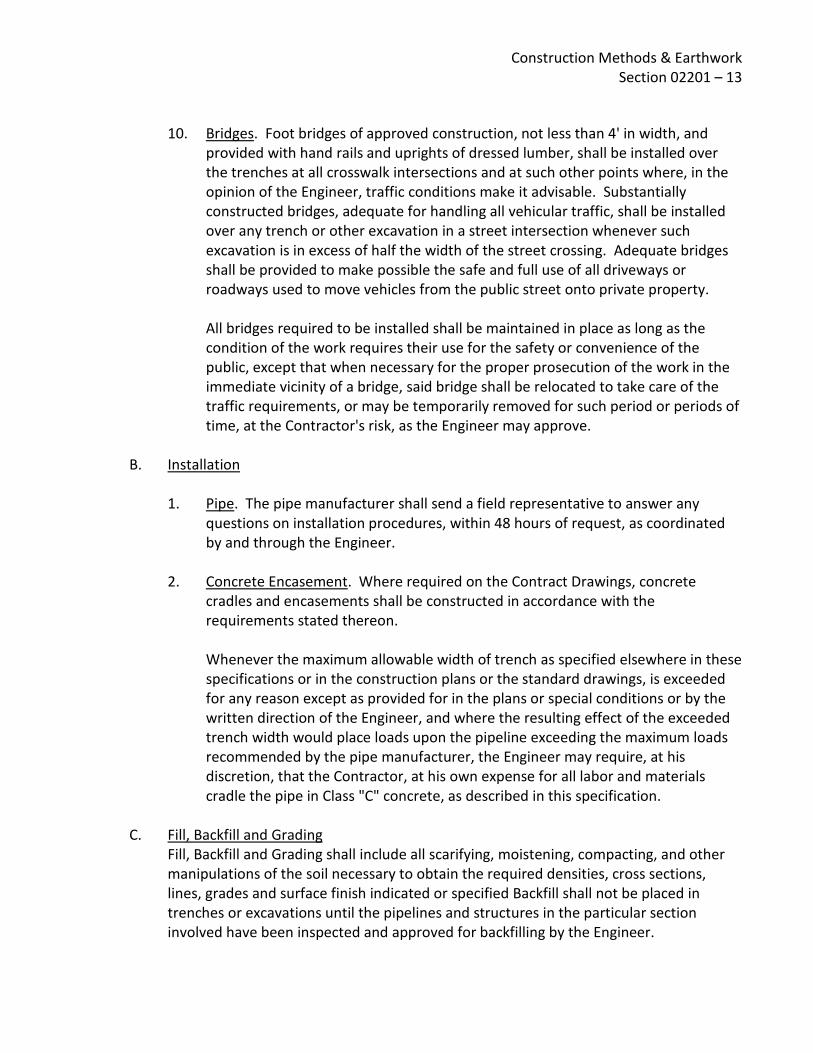
Construction Methods & Earthwork Section 02201 – 13
10. Bridges. Foot bridges of approved construction, not less than 4' in width, and provided with hand rails and uprights of dressed lumber, shall be installed over the trenches at all crosswalk intersections and at such other points where, in the opinion of the Engineer, traffic conditions make it advisable. Substantially constructed bridges, adequate for handling all vehicular traffic, shall be installed over any trench or other excavation in a street intersection whenever such excavation is in excess of half the width of the street crossing. Adequate bridges shall be provided to make possible the safe and full use of all driveways or roadways used to move vehicles from the public street onto private property. All bridges required to be installed shall be maintained in place as long as the condition of the work requires their use for the safety or convenience of the public, except that when necessary for the proper prosecution of the work in the immediate vicinity of a bridge, said bridge shall be relocated to take care of the traffic requirements, or may be temporarily removed for such period or periods of time, at the Contractor's risk, as the Engineer may approve.
B. Installation 1. Pipe. The pipe manufacturer shall send a field representative to answer any
questions on installation procedures, within 48 hours of request, as coordinated by and through the Engineer.
2. Concrete Encasement. Where required on the Contract Drawings, concrete cradles and encasements shall be constructed in accordance with the requirements stated thereon. Whenever the maximum allowable width of trench as specified elsewhere in these specifications or in the construction plans or the standard drawings, is exceeded for any reason except as provided for in the plans or special conditions or by the written direction of the Engineer, and where the resulting effect of the exceeded trench width would place loads upon the pipeline exceeding the maximum loads recommended by the pipe manufacturer, the Engineer may require, at his discretion, that the Contractor, at his own expense for all labor and materials cradle the pipe in Class "C" concrete, as described in this specification.
C. Fill, Backfill and Grading Fill, Backfill and Grading shall include all scarifying, moistening, compacting, and other manipulations of the soil necessary to obtain the required densities, cross sections, lines, grades and surface finish indicated or specified Backfill shall not be placed in trenches or excavations until the pipelines and structures in the particular section involved have been inspected and approved for backfilling by the Engineer.

Construction Methods & Earthwork Section 02201 – 14
Backfill shall be placed, insofar as practical, as the work progresses, allowing time for concrete (if used) to attain sufficient strength. All excavations outside the completed pipelines and structures shall be backfilled with compacted material to the level of the original ground surface unless otherwise shown on the drawings or ordered by the Engineer. The materials used for backfill shall be imported, selected material, or approved selected excavated materials and shall be placed as directed by the Engineer. All materials placed within 6" of the pipe or structure shall be free from rocks or boulders larger than 1 1/2" maximum dimension, and from unbroken masses of earthy materials which might lodge and thereby cause unfilled pockets in the excavation. Unsuitable material encountered at the surface upon which the bedding material is to be placed shall be removed to a depth as determined in the field by the Engineer. Unsuitable material shall be as determined by the Engineer. If not otherwise specified, removal of material and additional bedding so ordered over and above the amount required will be paid for in accordance with the specifications unless, however, the necessity for such additional bedding materials has been occasioned by an act or failure to act on the part of the Contractor, in which event the Contractor shall bear the expense of the additional excavation and backfill to the required depth. The Contractor's attention is called "dewatering" procedures to ensure that an otherwise stable foundation will not be rendered unfit due to accumulation of water in the trench excavation. However, the Contractor has the responsibility to reasonably ascertain the soil conditions prior to bid. The cost of removing the unsuitable materials should have been known prior to bid and be included in the bid price. Imported materials (if any) required for fill or backfill shall be provided by the Contractor from areas outside the site at his own expense. Such material shall be as herein specified and must be approved by the District before delivery to the site. 1. Structure Backfill. The Contractor shall place all backfill about structures to the
original ground level, or to the lines shown on the drawings or prescribed by the Engineer. Fill materials shall be of earth only, and be free from debris, vegetation, alkali, or other deleterious substances. All backfill about structures shall be placed in layers not more than 6" thick prior to compaction, which shall be obtained by moistening to optimum moisture content prior to placing and compacting to maximum compaction by use of suitable equipment approved by the Engineer. The Contractor shall take all necessary precautions to protect the structure and underground facilities during the placement, compacting or consolidating, and grading of backfill.

Construction Methods & Earthwork Section 02201 – 15
2. Pipeline Backfill. Full-time observation and testing will be required during all backfill and compaction activities on pipelines by a District approved soils firm. Except as otherwise required by the construction plans or the standard drawings, the material used in backfilling to 1' above the pipe shall be granular material approved by the Engineer and in accordance with the manufacturers requirements, sandy, or sandy gravel material obtained from required excavation or from approved borrow areas, as shown on the Contract Drawings or as directed by the Engineer. This material shall be carefully placed and compacted to provide a firm continuous bedding and encasement for the pipe. Pipe shall be shaded the same day it is laid to protect it from possible damage and/or thermal expansion. Pipe zone backfill may be consolidated by careful flooding to saturation only if the soil has a Sand Equivalent of 30 or better and no more than 10% fines (particles passing the no. 200 sieve), otherwise mechanical compaction will be required or as specified elsewhere in these specifications. Variations to the foregoing pipeline backfill requirement, when recommended by the pipe manufacturer or requested by the Contractor, shall be submitted for approval by the District prior to the commencement of such pipe installation. The method of compaction shall then be proven before backfilling more than the footage of pipe allowed by the contract specification. In lieu of a specific contract requirement, not more than 1000' of pipe shall be laid and backfilled prior to proving the method of compaction. The remaining trench backfill shall consist of select backfill material from the excavation, when available, free from stones or lumps exceeding 3" in greatest dimension, and free from vegetable matter or other unsatisfactory material. This select material as defined herein and elsewhere in these specifications shall be placed in layers not exceeding 2' in depth, unless otherwise directed by the Engineer. Excavated soils that have excessive moisture must be dried, mixed, or replaced with suitable material that will meet the compaction requirements at no additional cost to EMWD. Each lift shall be consolidated in such a manner that the backfill will meet the requirements of these specifications. Care shall be taken not to disturb the backfill previously placed, and the Contractor shall at all times protect the pipe against flotation. Material placed between successful test and failed test shall be tested at one-fifth (1/5) the distance intervals until a passing test is achieved. All material from failed test to successful test shall be removed, recompacted and retested.
3. Sewer Line Backfill. Backfill shall not be placed in trenches or excavations until the sewer lines and manholes in the particular section involved have been inspected and approved for backfilling by the Engineer.

Construction Methods & Earthwork Section 02201 – 16
For all sewer pipe, select granular backfill having a Sand Equivalent of 30 and less than 10% fines (particles passing the no. 200 sieve) shall be used up to an elevation 12" above the top of pipe, imported whenever the Engineer determines that native material is not satisfactory. Material for this purpose shall conform to the requirements as set forth herein. The pipe zone backfill shall be carefully packed under the haunches of the pipe and brought up simultaneously on both sides, to the full specified depth, so as to prevent any displacement of the pipe from its true alignment. In compacting by flooding, no ponding of water above the surface of the sand will be permitted.
4. Water Line Backfill. Prior to backfilling, all pipe 30" in diameter and larger shall be either filled with water under pressure or braced with stulls sufficiently to prevent distortion while placing, consolidating and compacting back fill. Prior to backfilling, all trench supports shall be removed unless otherwise approved by the Engineer.
5. Gravel Fill. Gravel fill shall be placed where specified, indicated on the plans, or designated by the Engineer to meet special conditions encountered. Where gravel fill is required, crushed rock may be substituted or added. Crushed rock for foundations shall be as defined for pipe bedding which is described elsewhere in this specification. The percentage composition by weight of gravel fill shall conform to the following grading when determined by Test Method No. Calif. 202:
Sieve Sizes Percentage Passing Sieves 1” ¾" No. 4 No. 30 No. 200
100 85-100 35-55 10-30 2-9
6. Compacting and Surfacing. Except as otherwise specifically required by the
encroachment permit or elsewhere in these specifications, the following requirements will apply: The upper portion of the final lift will be backfilled with selected material from the excavation, moistened to optimum moisture content and compacted by mechanical tamping to meet the requirements of the District standards. All backfill in public roads shall be consolidated and surfacing shall be placed to meet State of California and Riverside County requirements as stated in the respective permit, whether or not required by the inspector for that particular agency - unless otherwise approved by the Engineer.

Construction Methods & Earthwork Section 02201 – 17
Where backfill is in areas not within public roads, it shall be consolidated and tested to meet the requirements of these specifications, except as otherwise approved by the Engineer. Minimum acceptable field densities specified in District standards shall be determined in accordance with the testing procedures set forth elsewhere in these specifications. Where sand material of an approved grade is used for backfilling, mechanical compaction may be eliminated and compaction obtained by jetting. Except as otherwise required by a specific permit, where pavement is being replaced, an approved plant mixed surfacing shall be placed to a minimum thickness of 3" when compacted. Surfacing in streets shall be maintained to original street grade after laying and any settlement filled with plant mix surfacing. The edges of trenches which are broken down during the making of subgrade shall be removed and trimmed neatly before refilling or resurfacing. When the backfill is complete and excess material removed, the surface will be graded and a layer of approved decomposed granite will be placed with a minimum thickness of 4" when compacted at optimum moisture content by rolling and to a grade to conform to the original roadway section. All pavements outside the paylines damaged by the Contractor shall be trimmed and repaired. If the edge of the excavated trench when trimmed is within 2' of the edge of the roadway pavement, then the pavement shall be completely removed to the edge of the roadway and replaced with the replacement of the trench pavement. Except as otherwise directed by the Engineer, after a period of not less than 30 days or more than 60 days, any settlement shall be filled with decomposed granite. The top 2½" shall then be road mixed where allowed, with a minimum of 1½ gallons liquid asphalt binder of grade SC3 or 4 (as directed) per square yard and compacted to the original roadway section. Each phase shall be approved by the Engineer before proceeding to the next operation. Where allowed, the road-mixed surfacing operation shall conform to the Standard Specifications of the State of California Department of Transportation. Pavement, curbs, gutters and walks removed, cut or damaged during the construction of facilities shall be replaced or restored to their original condition, or as otherwise specified. Local ordinances governing such replacement shall be adhered to in all respects.

Construction Methods & Earthwork Section 02201 – 18
Removal and/or replacement of pavement where pavement now exists, as well as removal and/or replacement of any other obstructions, will be included in the item cost for the particular installation, unless specifically itemized separately on the bidding sheet.
D. Paving Where not required otherwise by specific contract requirements or permit requirements incorporated in the contract, the Contractor shall construct new asphalt concrete paving as indicated on the Contract Drawings and as specified herein. All paving proposals and operations shall be subject to the approval of the Engineer. Where this work is included in a lump sum bid item, it is the Contractor's responsibility to satisfy himself as to the exact lengths and/or dimensions of new roads and pavements. Terminals of all surfacing indicated on the Contract Drawings shall join any existing surfaces in a smooth juncture. 1. Sub-base
a) Preparation. The upper 12" of sub-base in any area to be paved shall be compacted to not less than 95% of maximum compaction, as determined by currently adopted ASTM D-1557 and procedure C.
b) Weed Killer. After the sub-base has been prepared, a weed killer shall be applied to the entire sub-base. Weed killer shall be OUST XP as manufactured by DUPONT, or approved equal. The weed killer shall be applied according to the manufacturer's published instructions.
2. Aggregate Base Course. Shall be Class II aggregate base. The aggregate base
course shall be the thickness shown on the plans and shall be placed in maximum 4" lifts. Aggregate base course shall be compacted to 95% of maximum compaction, as specified by ASTM D-1557. Aggregate base course shall be furnished, spread and compacted, as specified for Class II Aggregate Base Course in the Standard Specifications, State of California, Department of Transportation, latest edition. A spreader box will not be required but care shall be taken to prevent segregation during placement.
3. Asphalt Concrete a) Asphalt Concrete shall conform to the requirements of Caltrans Standard
Specifications Section 39, for Type "B". Aggregate will conform to a grading for 1/2" maximum aggregate with paving grade asphalt PG 64-10 (Section 92) unless otherwise directed by the Engineer.

Construction Methods & Earthwork Section 02201 – 19
b) Proportioning, Mixing, Spreading and Compacting. The proportioning and mixing of aggregates and asphalt, and the spreading and compacting of the asphalt concrete to make up the asphalt pavement, shall be in accordance with the Standard Specifications, State of California, Department of Transportation, latest edition. The paving machine shall have a self-screening spreader unless approved otherwise by the Engineer.
c) Tack Coat. Tack coat shall be Type SS1H grade Anionic Asphaltic Emulsion as per Caltrans Standard Specification 94.
d) Prime Coat. When indicated on the Plans or in the Special Provisions, a prime coat consisting of Grade SC-250 liquid asphalt shall be applied in accordance with Caltrans Standard Specification Sections 39 and 93.
e) Paving. The asphalt concrete pavement shall be no less than the thickness as shown on the plans and shall be applied in two (2) lifts. The first lift shall be the leveling course and the second lift shall be the wearing course not less than 1" thick and shall bring the pavement to full thickness. The finished surface shall be free from depressions exceeding 1/4" as measured with a 10-foot straightedge in any direction, except where the drawings show a grade break.
f) Seal Coat. Seal coat shall be a Bituminous Fog Seal in accordance with Caltrans Standard Specification Section 37.
g) Joining Existing Pavement. Existing paving which is to be joined by new paving shall be saw-cut to provide straight true neat joints.
h) Paving Headers. Edges of paving shall be bounded by 2 x 6 net new rough cut redwood unless otherwise shown on the plans.
i) Asphalt Curbs. Automatic curbing machines shall be used to construct asphalt curbs. The curb cross section used shall be as shown on the drawings or as approved by the District.
j) Paving Removal. Where paving is shown to be removed on the drawings, it shall mean that all asphaltic concrete and aggregate base shall be removed.
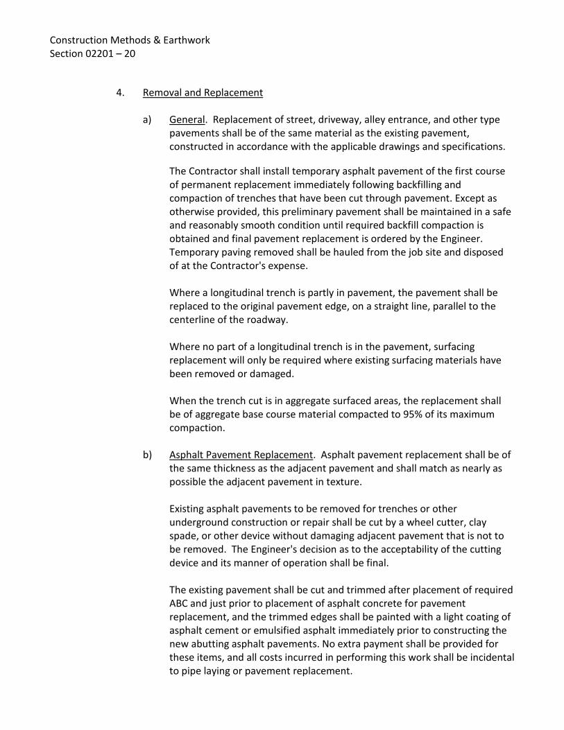
Construction Methods & Earthwork Section 02201 – 20
4. Removal and Replacement a) General. Replacement of street, driveway, alley entrance, and other type
pavements shall be of the same material as the existing pavement, constructed in accordance with the applicable drawings and specifications.
The Contractor shall install temporary asphalt pavement of the first course of permanent replacement immediately following backfilling and compaction of trenches that have been cut through pavement. Except as otherwise provided, this preliminary pavement shall be maintained in a safe and reasonably smooth condition until required backfill compaction is obtained and final pavement replacement is ordered by the Engineer. Temporary paving removed shall be hauled from the job site and disposed of at the Contractor's expense. Where a longitudinal trench is partly in pavement, the pavement shall be replaced to the original pavement edge, on a straight line, parallel to the centerline of the roadway. Where no part of a longitudinal trench is in the pavement, surfacing replacement will only be required where existing surfacing materials have been removed or damaged. When the trench cut is in aggregate surfaced areas, the replacement shall be of aggregate base course material compacted to 95% of its maximum compaction.
b) Asphalt Pavement Replacement. Asphalt pavement replacement shall be of the same thickness as the adjacent pavement and shall match as nearly as possible the adjacent pavement in texture. Existing asphalt pavements to be removed for trenches or other underground construction or repair shall be cut by a wheel cutter, clay spade, or other device without damaging adjacent pavement that is not to be removed. The Engineer's decision as to the acceptability of the cutting device and its manner of operation shall be final. The existing pavement shall be cut and trimmed after placement of required ABC and just prior to placement of asphalt concrete for pavement replacement, and the trimmed edges shall be painted with a light coating of asphalt cement or emulsified asphalt immediately prior to constructing the new abutting asphalt pavements. No extra payment shall be provided for these items, and all costs incurred in performing this work shall be incidental to pipe laying or pavement replacement.
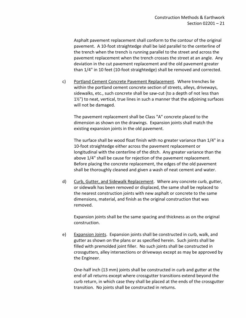
Construction Methods & Earthwork Section 02201 – 21
Asphalt pavement replacement shall conform to the contour of the original pavement. A 10-foot straightedge shall be laid parallel to the centerline of the trench when the trench is running parallel to the street and across the pavement replacement when the trench crosses the street at an angle. Any deviation in the cut pavement replacement and the old pavement greater than 1/4" in 10 feet (10-foot straightedge) shall be removed and corrected.
c) Portland Cement Concrete Pavement Replacement. Where trenches lie within the portland cement concrete section of streets, alleys, driveways, sidewalks, etc., such concrete shall be saw-cut (to a depth of not less than 1½") to neat, vertical, true lines in such a manner that the adjoining surfaces will not be damaged. The pavement replacement shall be Class "A" concrete placed to the dimension as shown on the drawings. Expansion joints shall match the existing expansion joints in the old pavement. The surface shall be wood float finish with no greater variance than 1/4" in a 10-foot straightedge either across the pavement replacement or longitudinal with the centerline of the ditch. Any greater variance than the above 1/4" shall be cause for rejection of the pavement replacement. Before placing the concrete replacement, the edges of the old pavement shall be thoroughly cleaned and given a wash of neat cement and water.
d) Curb, Gutter, and Sidewalk Replacement. Where any concrete curb, gutter, or sidewalk has been removed or displaced, the same shall be replaced to the nearest construction joints with new asphalt or concrete to the same dimensions, material, and finish as the original construction that was removed. Expansion joints shall be the same spacing and thickness as on the original construction.
e) Expansion Joints. Expansion joints shall be constructed in curb, walk, and gutter as shown on the plans or as specified herein. Such joints shall be filled with premolded joint filler. No such joints shall be constructed in crossgutters, alley intersections or driveways except as may be approved by the Engineer. One-half inch (13 mm) joints shall be constructed in curb and gutter at the end of all returns except where crossgutter transitions extend beyond the curb return, in which case they shall be placed at the ends of the crossgutter transition. No joints shall be constructed in returns.

Construction Methods & Earthwork Section 02201 – 22
Where monolithic curb and gutter is constructed adjacent to concrete pavement, no expansion joints will be required except at EC and BC of curb returns. Expansion joint filler 1/4" (6 mm) thick shall be placed in walk at the EC and BC of all walk returns, around all utility poles which may project into the concrete along the line of the work, and in walk returns between the walk and the back of curb returns when required by the Engineer. At the EC and BC and around utility poles, the joint filler strips shall extend the full depth of the concrete being placed. Joint filler strips between walk and curb shall be the depth of the walk plus 1" (25 mm) with the top set flush with the specified grade of the top of curb. All expansion joint filler strips shall be installed vertically, and shall extend to the full depth and width of the work in which they are installed, and be constructed perpendicular to straight curb or radially to the line of the curb constructed on a curve. Expansion joint filler materials shall completely fill these joints to within 1/4" (6 mm) of any surface of the concrete. Excess filler material shall be trimmed off to the specified dimension in a neat and workmanlike manner. During the placing and tamping of the concrete, the filler strip shall be held rigidly and securely in proper position.
f) Weakened Plane Joints. (i) General. Weakened plane joints shall be straight and constructed in
accordance with Subsections "Control Joint" and "Plastic Control Joint" below, unless otherwise shown on the drawings. In walk, joints shall be tranverse to the line of work and at regular intervals not exceeding 10' (3 m). At curves and walk returns, the joints shall be radial. In gutter, including gutter integral with curb, joints shall be at regular intervals not exceeding 20' (6 m). Where integral curb and gutter is adjacent to concrete pavement, the joints shall be aligned with the pavement joints where practical.
(ii) Control Joints. After preliminary troweling, the concrete shall be parted to a depth of 2" (50 mm) with a straightedge to create a division in the coarse aggregate. The concrete shall then be refloated to fill the parted joint with mortar. Headers shall be marked to locate the weakened plane for final joint finishing, which shall be accomplished with a jointer tool having a depth of ½" (13 mm) and a radius of 1/8" (3 mm). The finished joint opening shall not be wider than 1/8” (3 mm).

Construction Methods & Earthwork Section 02201 – 23
(iii) Plastic Control Joints. The joint material shall be a T-shaped plastic strip at least 1" (25 mm) deep, having suitable anchorage to prevent vertical movement, and having a removable stiffener with a width of at least 3/4" (20 mm). After preliminary troweling, the concrete shall be parted to a depth of 2" (50 mm) with a straightedge. The plastic strip shall be inserted in the impression so that the upper surface of the removable stiffener is flush with the concrete. After floating the concrete to fill all adjacent voids, the removable stiffener shall be stripped. During final troweling, the edges shall be finished to a radius of 1/8" (3 mm) using a slit jointer tool.
3.04 FIELD QUALITY CONTROL
A. Contractor's Responsibility for Safety The Contractor shall be responsible for initiating, maintaining, and supervising all safety precautions and programs in connection with the work. This requirement will apply continuously 24 hours a day every day until final acceptance of the work and shall not be limited to normal working hours.
B. Warnings and Barricades The Contractor shall provide and maintain barricades, guards, temporary bridges and walkways, watchmen, night lights and danger signals illuminated from sunset to sunrise, and all other necessary appliances and safeguards to protect the work, life, property, the public, excavations, equipment, and materials. Barricades shall be of substantial construction and shall be painted such as to increase their visibility at night. Suitable warning signs shall be so placed and illuminated at night as to show in advance where construction, barricades, or detours exist. Guard rails shall be provided for bridges and walkways over or adjoining excavations, shafts, and other openings and locations where injury may occur.
C. Fire Prevention The Contractor's Safety Officer shall inspect the entire work and site, including storage areas, at frequent intervals to verify that fire prevention measures are constantly enforced.
D. Fire Extinguishers and Hoses The Contractor shall furnish and maintain fully charged fire extinguishers of the appropriate type, supplements with temporary fire hoses wherever an adequate water supply exists, at the places where burning, welding, or other operations that may cause a fire are being performed.

Construction Methods & Earthwork Section 02201 – 24
E. Flammable or Toxic Materials Only a working supply of flammable or toxic materials shall be permitted on or on any of the permanent structures and improvements, and shall be removed therefrom at the end of each day's operations. The Contractor shall store flammable or toxic materials and waste separate from the work and stored materials for the work in a manner that prevents spontaneous combustion or dispersion, and none shall be placed in any sewer or drain piping nor buried on the site.
F. Safety Helmets, Clothing, and Equipment The Contractor shall not permit any person for whom he is responsible or liable to enter or remain on the site of the work unless the person is equipped with and wearing a safety helmet and other protective clothing and safety equipment conforming to the requirements of the District or regulatory agencies, and shall discharge from the site all persons not so equipped. The Contractor shall post conspicuous signs at appropriate locations warning the public and persons engaged upon the work of this requirement. The Contractor shall furnish for their temporary use such safety helmets, protective clothing, and safety equipment as the Engineer may request of him.
G. Hazardous Areas The Contractor shall not permit or allow any person or persons to enter any pipe or space containing hazardous or noxious substances or gases, or where there is an insufficient amount of oxygen to sustain life and consciousness, or any other hazardous area unless equipped with lawful and appropriate safety equipment and life-supporting apparatus, and unless those entering are continually monitored and guarded by and in communication with other persons outside the space or area who are equipped in the same way, can give an alarm to others for assistance, and initiate immediate rescue operations in the event of mishap.
H. Work During an Emergency
The Contractor shall perform any and all operations and shall furnish any materials and equipment necessary during an emergency endangering life or property and, in all cases, shall notify the District of the emergency as soon as practical, but shall not wait for instruction before proceeding to properly protect both life and property. Any additional compensation or extension of contract time claimed by the Contractor on account of an emergency shall be applied for as provided in the specifications.
I. Compaction Tests All compaction tests required by either the governing agency having jurisdiction over the right-of-way or by the District shall be performed by the District or its agent at District expense. However, in the event these tests prove the compaction to be unacceptable to either the governing agency or the District, all subsequent tests required by the governing agency or the District shall be performed at the Contractor's expense.

Construction Methods & Earthwork Section 02201 – 25
Tests will be scheduled within 24 hours of the Contractor's request for tests, at locations to be selected by the District and/or the governing agency. However, tests shall not be scheduled until a minimum 4-hours work is available for the testing laboratory, as determined by the Engineer. Results of these tests shall then be available within 48 hours. In-place soil densities shall be determined by the sand cone method of test in accordance with currently adopted ASTM Standard D-1556, or by the nuclear method of test in accordance with ASTM Standard D-2922. Optimum soil moisture-compaction relations shall be determined by the method of test specified in ASTM Standard D-1557, except as otherwise specified in the Special Conditions. Soils testing provided by EMWD to determine compliance with the requirements of this specification does not relieve the Contractor of his/her responsibility. In accordance with provisions for guarantee of the work, the Contractor shall return at his expense to correct any backfill conditions subsequently found to be substandard by either failure or more extensive testing. The Contractor shall provide all labor and equipment necessary to prepare for all tests and to assist the soils engineer in taking the tests, as directed by the Engineer.
J. Clean-up During Construction The Contractor shall keep the premises occupied by him in a neat and clean condition, and free from unsightly accumulation of rubbish. Upon completion of the work and before the final estimate is submitted, the Contractor shall, at his own cost and expense, satisfactorily dispose of or remove from the vicinity of the work all plants, buildings, rubbish, rock, unused and excavated materials belonging to him or used under his direction during the construction, and in the event of his failure to do so, the same may be removed and disposed of by the District at the Contractor's expense. Contractor's responsibility shall include satisfactory disposal of all debris or protective material resulting from material delivery such as plastic wrappings, pipe stulls, etc., whether or not the Contractor furnished such material. The Contractor shall carry on his operations in such sequence and in such manner as to interfere as little as possible with other improvements. When the construction is adjacent to or on residential property or cultivated fields or orchards, disposal of material and backfill operations shall be performed in such manner as to restore the properties to their original condition as nearly as practical as determined by the Engineer. Topsoil shall be carefully removed, stockpiled, and replaced after the backfill is placed.

Construction Methods & Earthwork Section 02201 – 26
As a part of the clean-up operation on facilities in private right-of-way, the Contractor shall restore the soil the full width of the right-of-way to a mechanical condition equivalent to that which existed at the time of the construction operations on such areas, by thoroughly loosening the soil with subsoilers, or other acceptable means and by discing and leveling if necessary, any stones, gravel, or other deleterious material left in spoil banks. On such lands debris shall be removed by the Contractor before his final preparation of the soil and shall bedisposed of as required for excavated materials. In unimproved areas the finish surfaces over pipelines shall be graded to drain surface water away from the center line of the actual trench and provide drainage away from all the structures. No ponding of surface water will be allowed within the construction right-of-way. Contractor shall complete total trench restoration (original condition or better) within 1,320 feet of trench heading or within 10 working days of construction, whichever represents the least amount of time. Failure of the contractor to comply with the Engineer's cleanup orders may result in an order to suspend work until the condition is corrected. No additional compensation will be allowed as a result of such suspension.
END OF SECTION 02201
Rev: 05/28/10
SPECIFICATIONS - DETAILED PROVISIONS
Section 02210 - Site Grading
C O N T E N T S PART 1 - GENERAL ............................................................................................................................. 1
1.01 REQUIREMENT .......................................................................................................................... 1 1.02 STRUCTURE PROTECTION ......................................................................................................... 2 1.03 JOB CONDITIONS ....................................................................................................................... 3
PART 2 - PRODUCTS .......................................................................................................................... 4 2.01 MATERIALS ................................................................................................................................ 4
PART 3 - EXECUTION ......................................................................................................................... 4 3.01 WEATHER LIMITATIONS ............................................................................................................ 4 3.02 PREPARATION ........................................................................................................................... 5 3.03 CONSTRUCTION ........................................................................................................................ 5 3.04 FIELD QUALITY CONTROL .......................................................................................................... 6


Site Grading Section 02210 – 1
SECTION 02210 SITE GRADING
PART 1 - GENERAL
1.01 REQUIREMENT
A. Verification of Existing Conditions. It shall be the responsibility of the Contractor to examine the site of the work and to make all investigation necessary, both surface and subsurface, to determine the character of materials to be encountered and all other existing conditions affecting the work.
B. Site Grading. Grading of site shall include all excavation, fill construction, access roads, and final grading, all in accordance with these specifications, and as shown on the drawings and as directed by the Engineer. The entire site within the area affected by construction shall be cleared and bladed. Surfaces shall be cut or filled, to the extent indicated, to finish grade stakes set by the Engineer. Finish surfaces shall slope uniformly between spot elevations or finish contour lines shown on the drawings and away from structures. Grading tolerance will be plus or minus .05 feet from surface elevations indicated. Clearing and Grubbing. All surfaces to receive compacted fill should be cleared of existing vegetation, debris, and other unsuitable materials. Abandoned underground utility lines should be traced out, securely capped at their entrance and exit to the site, and removed from the site. Concrete irrigation lines may be capped at their entrance and exit to the site, crushed in place and distributed throughout the fill as directed by the Soil Engineer. Soils which are loosened due to the removal of trees should be removed and replaced as controlled compacted fill under the direction of the Soil Engineer.
C. Lines, Grades and Measures. All lines and grades will be established by the Engineer and the Contractor shall provide him with such assistance and materials as may be required. The Contractor shall carefully preserve all survey stakes and reference points so far as possible. Should any stakes or points be removed or destroyed unnecessarily by any act of the Contractor or his employees, they may be reset at the Contractor's expense. The Contractor shall inform the Engineer a reasonable length of time in advance of the times and places at which he intends to work in order that lines and grades may be furnished, inspection provided, and necessary measurements for records and payments may be made with minimum inconvenience.

Site Grading Section 02210 – 2
D. Compliance with Regulations. The Contractor shall familiarize himself, and comply with all applicable state, county and municipal rules and regulations pertaining to sanitation, fire protection and safety.
E. Contractor's Equipment. The Contractor shall provide such modern plant and equipment as may be necessary in the opinion of the Engineer to perform in a satisfactory and acceptable manner, and in accordance with the specifications, all the work required of the Contractor.
F. Representatives for Emergencies. The Contractor shall file with the District a written list giving the names, addresses, and telephone numbers of at least two (2) of his representatives who can be contacted at any time in case of emergency. The representatives shall be fully authorized and equipped to correct unsafe or inconvenient conditions on short notice. The Contractor shall promptly notify the District of all changes in the listing.
G. Power and Water Supply. The Contractor shall provide at his own expense all necessary power required for his operations under the contract. The Contractor shall provide and maintain in good order such modern power equipment as shall be adequate in the opinion of the Engineer to perform in a safe and satisfactory manner the work required by the contract. The Contractor may obtain water for work under this specification from the source(s) described in the Special Provisions and Requirements of this specification.
1.02 STRUCTURE PROTECTION
A. Contract Drawings. The drawings show the position of various pipes and conduits and other structures as they are supposed to exist in construction areas, but no error or omission on said drawings shall be construed to relieve the Contractor from the responsibility of protecting any such pipe, conduit, or other structure. When deemed necessary by the Engineer, revisions of the contract drawings and additional detailed drawings will be issued to the Contractor during the progress of the work.
B. Notification of Underground Service Alert of Southern California. When performing underground work, the Contractor shall call Underground Service Alert (USA), the one-call underground facility locating service two (2) working days prior to making an excavation. Contractor shall be responsible for such notification of subcontractor's work, or shall require subcontractor or assume this responsibility.

Site Grading Section 02210 – 3
C. Operation of Utilities. No District valves or appurtenances of other utility facilities shall
be operated by the Contractor without approval and/or instruction from the District or the utility, as appropriate.
D. Maintenance of Utilities. Insofar as practical during the progress of the work, the property of any owner of a public utility pipeline or conduit, sewer, culvert, storm drain, drainage ditch, flood control channel, overhead wires or cables, or underground wires or cables, or any other structure or facility shall not be disturbed but shall be supported and protected against injury and maintained in good operating condition at the expense of the Contractor. In no case shall any such property be disturbed or removed without the consent of the owner and approval of the Engineer. The Contractor shall be responsible for making good all damage due to his operations, and the provisions of this section shall not be abated even in the event such damage occurs after backfilling, or is not discovered until after completion of backfilling. The locations of existing underground utilities and structures, insofar as they are known from information furnished by the respective utility companies and agencies, have been shown on the Drawings. It shall be the responsibility of the Contractor to verify the locations of these obstructions and to locate any other underground utilities and structures which might necessitate a change in the line and grade of the new work. If the Contractor, while performing the work of construction, discovers utility facilities not identified by the District in contract plans or specifications, he shall immediately notify the District in writing. In no case shall any utility that has been damaged, whether shown or not shown on the plans, be backfilled without the Contractor notifying the utility company of the damage.
E. Utility Construction. The District may require the moving, altering or reconstructing of obstructing underground facilities, sewers, or storm drains, and compensation therefore will come under extra work where such work is ordered in writing by the Engineer. Pipelines determined to be abandoned may be destroyed if conflicting with the contract work and properly disposed of. Exposed ends of abandoned pipelines shall be plugged for water tightness as approved by the Engineer.
1.03 JOB CONDITIONS
A. Rights-of-Way and Land. The District will provide the rights-of-way and acquire the land necessary for the construction of the work under this specification. Neither the terms hereof nor anything shown on the drawings shall be construed to entitle the Contractor to conduct operations off the site in violation of any public agency ordinance or regulation restricting interference with water courses, drainage channels, roads, alleys or streets, until he has obtained permits therefore from the proper authorities.

Site Grading Section 02210 – 4
In any street in which his work may interfere with ingress or egress of the occupants of the abutting property or of their vehicles, the Contractor shall maintain temporary practicable means of ingress and egress, or shall make satisfactory arrangements with the occupants for the obstructing of ways to their properties for the duration of the interference. Nothing herein shall be construed to entitle the Contractor to the exclusive use of any public street or way during the performance of the contract work, and he shall so conduct his operations as not to interfere unnecessarily with the authorized work of other agencies in such streets and ways.
B. Safeguarding Excavations and Property. Excavations shall be adequately shored and braced so that the earth will not slide or settle and so that all existing improvements of any kind will be fully protected from damage. Any damage resulting from a lack of adequate shoring and bracing shall be the responsibility of the Contractor. The Contractor shall affect all necessary repairs or reconstructions at the Contractor's own expense as directed by the Engineer and shall bear all other expense result-directed by the Engineer and shall bear all other expense resulting from such damage.
C. Waste Water. The Contractor shall take care of drainage water on construction operations and of storm water and waste water reaching the right of way from any source so that no damage will be done to the materials or work under construction. The Contractor shall be responsible for any damage to persons or property on or off the right of way due to such diversion of such storm or waste water on account of his operations. Adequate flumes shall be provided for conveying storm water around the work wherever runoff from tributary drainage areas exists.
PART 2 - PRODUCTS
2.01 MATERIALS The Contractor shall furnish all materials not specifically called for as furnished by the District.
PART 3 - EXECUTION
3.01 WEATHER LIMITATIONS Excavating and grading shall be performed only when the weather conditions do not adversely affect the quality of the finished product. Any graded or excavated areas that are damaged by the effect of rain, or other weather conditions, during any phase of the construction, shall be re-excavated, regraded, and recompacted to conform to the herein-specified requirements, without additional cost to the District.

Site Grading Section 02210 – 5
3.02 PREPARATION It shall be the responsibility of the Contractor to meet with the Engineer regarding the equipment and methods to be used in the construction of the work, and for approval of the order and schedule of work. Dust Abatement. The Contractor shall furnish all labor, equipment and means required and shall carry out protective measures wherever and as often as necessary to prevent his operations from producing dust in amounts damaging to property or causing nuisance. The Contractor shall be responsible for any damage resulting from dust originating from his operations. The dust abatement measures shall be continued until all required resurfacing is completed or until the Contractor has completed arrangements with the proper authorities whereby he is relieved of further responsibility. All compensation to be received for dust abatement shall be included in the prices named for appropriate items of the bidding sheet.
3.03 CONSTRUCTION
A. Excavation. The Contractor shall perform all excavations necessary or required for the construction covered by these specifications. Excavations may be performed by either hand of machine methods and shall be of sufficient size to provide adequate space for working there, in accordance with safety regulations and practice and the Contract Drawings. Excavations shall include the removal and disposal of all materials of whatever nature and quantity including water, rock, decomposed granite or any other type of soil or material, subsurface obstructions and also overhead obstructions which may interfere with the operation of equipment used on the work, for no additional compensation.
B. Blasting. The use of explosives on the work shall be subject to the approval of the Engineer. All operations involving the handling and storage and use of explosives shall be conducted with every precaution prescribed by the Construction Safety Orders of the Division of Industrial Safety of the State of California and by local laws and regulations. Only competent, reliable persons, working under experienced supervision, shall be permitted to use explosives. The Contractor will be held responsible for and shall make good any damage caused by blasting or otherwise resulting from disposition or use of explosives on the work. All such work involved in blasting shall be included in the prices bid for site grading.
C. Structure Backfill. The Contractor shall place all fill to the lines shown on the drawings or prescribed by the Engineer. The material used for backfill around structures, the amount thereof, and the manner of depositing the material shall be subject to approval of the Engineer.
D. Fill, Backfill and Grading shall include all scarifying, moistening, compacting, and other manipulations of the soil necessary to obtain the required densities, cross-sections, lines, grades and surface finish indicated or specified.

Site Grading Section 02210 – 6
Imported materials necessary for fill or backfill to meet the specified compaction requirements shall be provided by the Contractor from areas outside the site at his own expense. Such material shall be as herein specified and must be approved by the District before delivery to the site. All backfill around structures shall be placed in layers not more than six (6) inches thick prior to compaction, which shall be moistened to optimum moisture content prior to placing and compacting to maximum compaction by use of suitable equipment approved by the Engineer. The Contractor shall take all necessary precautions to protect any structures and/or underground facilities during the placement, compacting or consolidating, and grading or backfill.
3.04 FIELD QUALITY CONTROL
A. Disposal of Excavated Materials. Insofar as space is available in the right of way, such space may be used for temporary storage of excavated material, to be used for fill or backfill, provided that no material shall be stored or deposited in violation of any ordinance or regulation prohibiting the filling or obstructing of water courses in drainage channels. Storage of excavated material in any street or highway shall conform to the regulations of the public authority having jurisdiction thereover. All materials removed from the excavations in excess of that stored temporarily as above specified shall be immediately hauled away and used in backfilling elsewhere, or, if not used, shall be disposed of by the Contractor. The disposal area shall be acquired by the Contractor. No materials shall be disposed of either temporarily or permanently on privately or publicly owned property unless the Contractor shall first obtain permission therefore from the owner or agency concerned. The Contractor shall furnish satisfactory evidence to the Engineer that such consent has been obtained and shall be responsible for all damages and claims that may arise in connection therewith.
B. Cleanup During Construction. The Contractor shall keep the premises occupied by him in a neat and clean condition, and free from unsightly accumulation of rubbish. Upon completion of the work and before the final estimate is submitted, the Contractor shall, at his own cost and expense, satisfactorily dispose of or remove from the vicinity of the work all plants, buildings, rubbish, rock, unused and excavated materials belonging to him or used under his direction during the construction, and in the event of his failure to do so, the same may be removed and disposed of by the District at the Contractor's expense.

Site Grading Section 02210 – 7
Fences on the right of way shall be removed by the Contractor where necessary for the performance of the work, and where required shall be rebuilt in as good condition as found. Where designated, fences shall be maintained until the work is completed or their removal is authorized. Where the Contractor removes existing fences to facilitate the work, temporary fence protection for lands adjacent to the right of way shall be provided at all times during the continuation of the contract. Such temporary fence protection shall be adequate to prevent livestock from straying from or onto adjacent lands and shall be constructed complete with gates and/or cattle guards. The cost of all work described in this article shall be included in the prices bid in this specification for other items of work.
END OF SECTION 02210

Site Grading Section 02210 – 8
[PAGE LEFT INTENTIONALLY BLANK]

Rev: 04/22/15
SPECIFICATIONS - DETAILED PROVISIONS
Section 02221 - Trenching, Backfilling, and Compacting
C O N T E N T S PART 1 - GENERAL ............................................................................................................................. 1
1.01 SUMMARY ................................................................................................................................. 1 1.02 STRUCTURE PROTECTION ......................................................................................................... 2 1.03 JOB CONDITIONS ....................................................................................................................... 2 1.04 GUARANTEE .............................................................................................................................. 3
PART 2 - PRODUCTS .......................................................................................................................... 3 2.01 MATERIALS ................................................................................................................................ 3
PART 3 - EXECUTION ......................................................................................................................... 4 3.01 WEATHER LIMITATIONS ............................................................................................................ 4 3.02 PREPARATION ........................................................................................................................... 4 3.03 CONSTRUCTION ........................................................................................................................ 4 3.04 FIELD QUALITY CONTROL .......................................................................................................... 9

Trenching, Backfilling, and Compacting Section 02221 – 1
SECTION 02221 TRENCHING, BACKFILLING, AND COMPACTING
PART 1 - GENERAL
1.01 SUMMARY
A. Trench, backfill, and compact as specified herein and as needed for installation of underground utilities associated with the work.
B. Verification of Existing Conditions. It shall be the responsibility of the Contractor to examine the site of the work and to make all investigation necessary, both surface and sub-surface, to determine the character of materials to be encountered and all other existing conditions affecting the work.
C. Lines, Grades and Measures. All lines and grades will be established by the Engineer, and the Contractor shall provide him with such assistance and materials as may be required. The Contractor shall carefully preserve all survey stakes and reference points. SHOULD ANY STAKES OR POINTS BE REMOVED OR DESTROYED BY ANY ACT OF THE CONTRACTOR OR HIS EMPLOYEES THEY MAY BE RESET AT THE CONTRACTOR'S EXPENSE.
D. Compliance with Regulations. The Contractor shall familiarize himself, and comply with all applicable federal, state, county and municipal rules and regulations pertaining to sanitation, fire protection, and safety.
E. Contractor's Equipment. The Contractor shall provide such modern plant and equipment as may be necessary in the opinion of the Engineer to perform in a satisfactory and acceptable manner, and in accordance with the specifications, all the work required of the Contractor.
F. Representatives for Emergencies. The Contractor shall file with the District a written list giving the names, addresses, and telephone numbers of at least two (2) of his representatives who can be contacted at any time in case of emergency. The representatives shall be fully authorized and equipped to correct unsafe or inconvenient conditions on short notice. The Contractor shall promptly notify the District of all changes in the listing.
G. Water Supply. The Contractor may obtain water for work under this specification from the sources as stated in the Special Provisions and Requirements of this specification.

Trenching, Backfilling, and Compacting Section 02221 – 2
1.02 STRUCTURE PROTECTION
A. Contract Drawings. The drawings identify the various pipes, conduits, and other existing utility structures as they are supposed to exist in construction areas, but no error or omission on said drawings shall be construed to relieve the Contractor from the responsibility of protecting any such pipe, conduit, or other existing utility structures. When deemed necessary by the Engineer, revisions of the contract drawings and additional detailed drawings will be issued to the Contractor during the progress of the work.
B. Notification of Underground Service Alert of Southern California. When performing underground work, the Contractor shall call Underground Service Alert (USA), the one-call underground facility locating service two (2) working days prior to making an excavation. Contractor shall be responsible for such notification of sub-contractor's work, or shall require sub-contractor to assume this responsibility.
C. Operation of Utilities. No District valves, or appurtenances of other utility facilities shall be operated by the Contractor without approval and/or instruction from the District or the utility, as appropriate.
1.03 JOB CONDITIONS
A. Safeguarding Excavations and Property. Excavations shall be adequately shored and braced so that the earth will not slide or settle and so that all existing improvements of any kind will be fully protected from damage. Any damage resulting from a lack of adequate shoring and bracing shall be the responsibility of the Contractor. The Contractor shall affect all necessary repairs or reconstructions at the Contractor's own expense as directed by the Engineer and shall bear all other expenses resulting from such damage.
B. Safety Measures. Each bid proposal submitted under these specifications for the construction of a pipeline, sewer, sewage disposal system, boring and jacking pits, or similar trenches or open excavations, or the use of such a trench or open excavation, shall include in appropriate bid items for such work the costs necessary to provide adequate sheeting, shoring, and bracing, or equivalent method for the protection of life or limb, which shall conform to applicable safety orders, including the Construction Safety Orders of the California Division of Industrial Safety, in accordance with the requirements of the California Occupational Safety and Health Act.

Trenching, Backfilling, and Compacting Section 02221 – 3
1.04 GUARANTEE The Contractor hereby guarantees that the entire work constructed by him under the contract will fully meet all the requirements thereof as to quality of workmanship, and of materials furnished by him.
PART 2 - PRODUCTS
2.01 MATERIALS
A. Select Backfill Material, and Special Bedding and Backfill. Select backfill material shall be selected from the excavated material or imported when not available from the excavated material. In either case, it shall be provided at the Contractor's expense, and shall be included in the costs proposed for pipeline installation on the bidding sheets. Provide soil materials free from organic matter and deleterious substances, containing no rocks over 3" in greatest dimension, and with no more than 15% of the rocks over 2" in their greatest dimension. Where called for on the plans or in these specifications, and not covered by a separate bid item, special bedding or backfill shall be included in pipeline construction costs on the bidding sheets. Where required by the governing agency or by the District to meet compaction requirements of these specifications, or requirements of these specifications for bedding or for select granular backfill, special bedding or imported backfill and disposal of excavated spoil shall be provided at the Contractor's expense. The requirements for special bedding and backfill at the Contractor's expense as described herein as a part of the Special Conditions or as shown on the Contract Drawings shall supersede and take precedence over any and all other requirements for measurement and/or payment for special bedding or backfill found elsewhere in these specifications. Bedding is defined herein to include sand, rock or concrete base, cradle, or encasement. Backfill material is defined herein to include backfill for both trench backfill and pipe bedding (or pipe zone backfill). Special bedding or backfill not called for on the plans or in these specifications, but required by the Engineer over and above the requirements of this specification, shall be constructed at additional cost, at prices reflecting current material costs as evidenced by paid vouchers, plus 50% to cover all costs of installation and overhead.

Trenching, Backfilling, and Compacting Section 02221 – 4
The encounter of ground water not anticipated in engineering reports made available for this contract, and the required over-excavation and construction of a stable base as determined necessary by the Engineer shall be considered over and above the requirements of this specification, and the required base shall be paid for at the above stipulated prices.
PART 3 - EXECUTION
3.01 WEATHER LIMITATIONS Excavating and grading shall be performed only when the weather conditions do not adversely affect the quality of the finished product. Any graded or excavated areas that are damaged by the effect of rain, or other weather conditions, during any phase of the construction, shall be re-excavated, regraded, and recompacted to conform to the herein specified requirements, without additional cost to the District.
3.02 PREPARATION
A. Control of Water. The Contractor shall acquire such permits and take such measures as may be required, and shall furnish, install, and operate such pumps or other devices as may be necessary to remove any seepage, storm water, or sewage that may be found or may accumulate in the excavations during the progress of the work. The Contractor shall keep all excavations entirely free from water at all times during the construction of the work and until the Engineer gives permission to cease pumping. He shall keep the complete work reasonably free from accumulations of water and sewage, and shall free it entirely at such times as may be required by the Engineer for inspection or other purposes. Any accumulated water or sewage thus pumped shall be disposed of in accordance with good practice and local ordinances. The Contractor shall provide an adequate dewatering system for the control of surface and groundwater seepage into the excavations as may be required during the construction period. The proposed plan of this dewatering system shall be submitted to the Engineer for concept approval prior to the installation of the system.
3.03 CONSTRUCTION
A. Excavation. The Contractor shall perform all excavation necessary or required for the construction of the facilities covered by these specifications. Excavations may be performed by either hand or machine methods and shall be of sufficient size to provide adequate space for working in accordance with safety regulations

Trenching, Backfilling, and Compacting Section 02221 – 5
and practice and the Contract Drawings. Excavations shall include the removal and disposal of all materials of whatever nature and quantity including water, rock, decomposed granite, or any other type of soil or material, subsurface obstructions and also overhead obstructions which may interfere with the operation of equipment used on the work, for no additional compensation. Excavation for foundations shall be made only after construction of subgrade, as hereinafter described, has been completed. Over excavation for foundations shall be filled with concrete. 1. Trench Excavation. Unless otherwise specified in the Special Conditions or on the
Contract Drawings, pipeline trenches and clearances shall be per Standard Drawing SB-158 for sewer pipeline installations and B-286B for water pipeline installations. The sides of the trench shall be parallel to and at equal distance on each side of the centerline of the pipe The maximum length of trench which shall be opened or partially opened at any one time shall be limited to 500' for sewer lines and one-half mile for water pipelines, except where governed by other agencies or approved by the Engineer. Bell holes or depressions shall be dug by hand at the proper locations of sufficient size to adequately work the joints, but no larger than is required. When the trench is excavated to the line and grade as shown on the drawings, and the bedding material encountered is rock, the trench shall be excavated an additional depth of at least 4" below the grade for the bottom of the pipe, and the bottom of the trench shall be refilled with approved material, moistened and compacted by tamping or by other approved method to the satisfaction of the Engineer. Where ground water is encountered and the native material does not afford a solid foundation for pipe subgrade as specified above, the Contractor shall excavate to such depth below subgrade as determined necessary by the Engineer and shall construct a stable base by placing crushed rock bedding upon which subgrade can be prepared. Crushed rock for bedding shall be one and one-half inch (1 1/2") maximum size. When the trench has been inadvertently excavated below the designed grade, at the Contractor's expense, the bottom of the trench shall be refilled with approved material, well compacted into place in an approved manner and to the satisfaction of the Engineer. Where it becomes necessary to excavate beyond the limits of normal excavation lines in order to remove boulders or other interfering objects, backfill the voids remaining, as directed by the engineer but not less than 90% of maximum compaction. This work is to be done at no extra cost to owner.

Trenching, Backfilling, and Compacting Section 02221 – 6
Where trenching occurs in existing turf areas, remove turf in sections and keep roots damp. Replace turf upon completion of backfilling.
2. Cover. Provide minimum trench depth indicated below to maintain a minimum cover over the top of each listed utility, unless otherwise indicated in specifications or on the drawings. a) 1. Water lines: 48" b) 2. Gas lines: 24" c) 3. Electrical lines: 36"
3. Excavated Materials. Shall be piled neatly along the side of the trench and adjacent to manhole excavations in such a manner as to be of as little inconvenience as possible to the public traffic or the occupants of the adjacent property. Through all cultivated areas, topsoil removed from excavations shall be replaced as backfill in the uppermost part of the excavation to a depth as it existed previous to excavation, not exceeding 18". Where topsoil replacement is required, excavated topsoil shall be stored separately from other materials and in general shall be replaced as backfill in the same parcel of land from which it came.
4. Disposal of Excavated Materials. Insofar as space is available in the right-of-way, such space may be used for temporary storage of excavated material, to be used for backfill, provided that no material shall be stored or deposited in violation of any ordinance or regulation prohibiting the filling or obstructing of water courses in drainage channels. All materials removed from the excavations in excess of that stored temporarily as above specified shall be immediately hauled away and used in backfilling elsewhere, or, if not used, shall be disposed of by the Contractor. The disposal area shall be acquired by the Contractor. No materials shall be disposed of either temporarily or permanently on privately or publicly owned property unless the Contractor shall first obtain permission therefore from the owner or agency concerned. The Contractor shall furnish satisfactory evidence to the Engineer that such consent has been obtained and shall be responsible for all damages and claims that may arise in connection therewith.
5. Bracing and Shoring. The Contractor shall furnish, place and maintain such bracing and shoring as may be required to support the side of the excavations for the proper protection of workmen, to facilitate the work and prevent damage to the pipes and manholes being constructed, and to prevent damage to adjacent structures or facilities. Upon completion of the work, all bracing and shoring shall be removed unless otherwise directed or permitted by the Engineer.
Trenching, Backfilling, and Compacting Section 02221 – 7
B. Fill, Backfill and Grading shall include all scarifying, moistening, compacting, and other manipulations of the soil necessary to obtain the required densities, cross sections, lines, grades and surface finish indicated or specified. Backfill shall not be placed in trenches or excavations until the pipelines and structures in the particular section involved have been inspected and approved for backfilling by the Engineer. All excavations outside the completed pipelines and structures shall be backfilled with compacted material to the level of the original ground surface unless otherwise shown on the drawings or ordered by the Engineer. The materials used for backfill shall be imported, selected material, or approved selected excavated materials and shall be placed as directed by the Engineer. All materials placed within 6" of the pipe or structure shall be free from rocks or boulders larger than 1 1/2" maximum dimension, and from unbroken masses of earthy materials which might lodge and thereby cause unfilled pockets in the excavation. Unsuitable material encountered at the surface upon which the bedding material is to be placed shall be removed to a depth as determined in the field by the Engineer. Unsuitable material shall be as determined by the Engineer. If not otherwise specified, removal of material and additional bedding so ordered over and above the amount required will be paid for in accordance with the specifications unless, however, the necessity for such additional bedding materials has been occasioned by an act or failure to act on the part of the Contractor, in which event the Contractor shall bear the expense of the additional excavation and backfill to the required depth. The Contractor's attention is called to “dewatering" procedures to ensure that an otherwise stable foundation will not be rendered unfit due to accumulation of water in the trench excavation. Imported materials (if any) required for fill or backfill shall be provided by the Contractor from areas outside the site at his own expense. Such material shall be as herein specified and must be approved by the District before delivery to the site. 1. Structure Backfill. The Contractor shall place all backfill about structures to the
original ground level, or to the lines shown on the drawings or prescribed by the Engineer. Fill materials shall be of earth only, and be free from debris, vegetation, alkali, or other deleterious substances. All backfill about structures shall be placed in layers not more than 6" thick prior to compaction, which shall be obtained by moistening to optimum moisture content prior to placing and compacting to maximum compaction by use of suitable equipment approved by the Engineer.

Trenching, Backfilling, and Compacting Section 02221 – 8
The Contractor shall take all necessary precautions to protect the structure and underground facilities during the placement, compacting or consolidating, and grading of backfill.
2. Pipeline Backfill. Full-time observation and testing will be required during all backfill and compaction activities on pipelines by a District approved soils firm. Except as otherwise required by the construction plans or the standard drawings, the material used in backfilling to 1' above the pipe shall be cohesionless, sandy, or sandy gravel material obtained from required excavation or from approved borrow areas, as shown on the Contract Drawings or as directed by the Engineer. This material shall be carefully placed and compacted to provide a firm continuous bedding and encasement for the pipe. Pipe shall be shaded the same day it is laid to protect it from possible damage and/or thermal expansion. Pipe zone backfill shall be consolidated by mechanical tamping. Deposit approved backfill and bedding material, in the lower portion of the trench, in layers of 6" maximum thickness, and compact with suitable mechanical tampers to a density not less than 85%, or grade as specified in special conditions of contract, until there is a cover of not less than 24" for sewer lines and 12" over other utility lines. Care must be taken to not damage the pipe. The remaining trench backfill shall consist of select backfill material from the excavation, when available, free from stones or lumps exceeding 3" in greatest dimension, and free from vegetable matter or other unsatisfactory material. This select material as defined herein and elsewhere in these specifications, shall be placed in layers not exceeding 2’ in depth, unless otherwise directed by the Engineer. Each lift shall be consolidated in such a manner that the backfill will meet the requirements of compaction to 90% maximum density per ASTM D1557-09. Care shall be taken not to disturb the backfill previously placed, and the Contractor shall at all times protect the pipe against flotation. All material from failed test to successful test shall be removed, recompacted and retested.
3. Compacting and Surfacing. Except as otherwise specifically required by the encroachment permit or elsewhere in these specifications, the following requirements will apply: The upper portion of the final lift will be backfilled with selected material from the excavation, moistened to optimum moisture content and compacted by mechanical tamping to meet the requirements of the District standards, of 95% maximum compaction. All backfill in public roads shall be consolidated and surfacing shall be placed to meet State of California and Riverside County requirements as stated in the respective permit, whether or not required by the inspector for that particular agency - unless otherwise approved by the Engineer.

Trenching, Backfilling, and Compacting Section 02221 – 9
Where backfill is in areas not within public roads, it shall be consolidated and tested to meet the requirements of these specifications, except as otherwise approved by the Engineer. Minimum acceptable field densities specified in District standards shall be determined in accordance with the testing procedures set forth elsewhere in these specifications. Where sand material of an approved grade is used for backfilling, mechanical compaction may be eliminated and compaction obtained by jetting. Except as otherwise directed by the Engineer, after a period of not less than 30 days or more than 60 days, any settlement shall be filled with decomposed granite.
3.04 FIELD QUALITY CONTROL
A. Contractor's Responsibility for Safety. The Contractor shall be responsible for initiating, maintaining, and supervising all safety precautions and programs in connection with the work. This requirement will apply continuously 24 hours a day every day until final acceptance of the work and shall not be limited to normal working hours.
B. Warnings and Barricades. The Contractor shall provide and maintain barricades, guards, temporary bridges and walkways, watchmen, night lights and danger signals illuminated from sunset to sunrise, and all other necessary appliances and safeguards to protect the work, life, property, the public, excavations, equipment, and materials. Barricades shall be of substantial construction and shall be painted such as to increase their visibility at night. Suitable warning signs shall be so placed and illuminated at night as to show in advance where construction, barricades, or detours exist. Guard rails shall be provided for bridges and walkways over or adjoining excavations, shafts, and other openings and locations where injury may occur.
C. Compaction Tests. All compaction tests required by either the governing agency having jurisdiction over the right-of-way or by the District shall be performed by the District or its agent at District expense. However, in the event these tests prove the compaction to be unacceptable to either the governing agency or the District, all subsequent tests required by the governing agency or the District shall be performed at the Contractor's expense.

Trenching, Backfilling, and Compacting Section 02221 – 10
Tests will be scheduled within 24 hours of the Contractor's request for tests, at locations to be selected by the District and/or the governing agency. However, tests shall not be scheduled until a minimum 4-hours work is available for the testing laboratory, as determined by the Engineer. Results of these tests shall then be available within 48 hours. In-place soil densities shall be determined by the sand cone method of test in accordance with ASTM Standard D-1556-64, or by the nuclear method of test in accordance with ASTM Standard D-2922-071. In accordance with provisions for guarantee of the work, the Contractor shall return at his expense to correct any backfill conditions subsequently found to be substandard by either failure or more extensive testing. The Contractor shall provide all labor and equipment necessary to prepare for all tests and to assist the soils engineer in taking the tests, as directed by the Engineer. In unimproved areas the finish surfaces over pipelines shall be graded to drain surface water away from the center line of the actual trench and provide drainage away from all the structures. No ponding of surface water will be allowed within the construction right-of-way. Contractor shall complete total trench restoration (original condition or better) within 1,320 feet of trench heading or within 10 working days of construction, whichever represents the least amount of time. Failure of the contractor to comply with the Engineer's cleanup orders may result in an order to suspend work until the condition is corrected. No additional compensation will be allowed as a result of such suspension.
END OF SECTION 02221

Rev: 07/05
SPECIFICATIONS - DETAILED PROVISIONS Section 02444 - Chain Link Fencing
C O N T E N T S
PART 1 - GENERAL ............................................................................................................................. 1
1.01 DESCRIPTION ............................................................................................................................. 1 1.02 QUALITY ASSURANCE ................................................................................................................ 1 1.03 SUBMITTALS .............................................................................................................................. 1 1.04 JOB CONDITIONS ....................................................................................................................... 2 1.05 PAYMENT .................................................................................................................................. 2 1.06 GUARANTEE .............................................................................................................................. 2
PART 2 - PRODUCTS AND MATERIALS ................................................................................................ 3 2.01 POSTS AND BRACES .................................................................................................................. 3 2.02 CHAIN LINK FABRIC ................................................................................................................... 3 2.03 TENSION WIRE .......................................................................................................................... 3 2.04 TIE WIRE .................................................................................................................................... 4 2.05 BARBED WIRE ............................................................................................................................ 4 2.06 TRUSS RODS .............................................................................................................................. 4 2.07 HARDWARE ............................................................................................................................... 4 2.08 GALVANIZING ............................................................................................................................ 4 2.09 CLASS "B" CONCRETE ................................................................................................................ 4 2.10 GATES ........................................................................................................................................ 4
PART 3 - EXECUTION ......................................................................................................................... 5 3.01 POSTS ........................................................................................................................................ 5 3.02 CHAIN LINK FABRIC ................................................................................................................... 5


Chain Link Fencing Section 02444 – 1
SECTION 02444 CHAIN LINK FENCING
PART 1 - GENERAL
1.01 DESCRIPTION
A. Requirement. Under these specifications, the Contractor shall furnish all materials, labor, tools, and equipment required to completely construct the fencing, posts, gates, and miscellaneous material, including removal of trees, brush and other obstacles, as shown on the contract drawings and as specified in these specifications.
B. Rights-of-Way. All rights-of-way necessary for the construction of facilities under this specification will be provided for the Contractor. Neither the terms hereof nor anything shown on the drawings in connection with the right-of-way provided by the District, shall be construed to entitle the Contractor to conduct operations in said right-of-way in violation of any public agency ordinance or regulation restricting interference with water courses and drainage channels, road, alley, or street until he has obtained permits therefore from the proper authorities. Nothing herein shall be construed to entitle the Contractor to the exclusive use of any public street or way during performance of the contract work, and he shall so conduct his operations as not to interfere unnecessarily with the authorized work of other agencies in such streets and ways.
C. Power. The Contractor shall provide at his own expense all necessary power required for his operations under the contract. The Contractor shall provide and maintain in good order such modern power equipment and installation as shall be adequate in the opinion of the Engineer to perform in a safe and satisfactory manner the work required by the contract.
1.02 QUALITY ASSURANCE Contractor shall be responsible for the quality of all work of his forces and that of his subcontractors, for adherence to all laws and regulations, and for all public relations regarding the contract work, as set forth elsewhere in the contract documents.
1.03 SUBMITTALS Submittals are required only if the Contractor is proposing deviations from the requirements of the contract documents.

Chain Link Fencing Section 02444 – 2
1.04 JOB CONDITIONS Water Furnished by District. The District will make water available for construction at the locations stated in the Special Provisions.
1.05 PAYMENT
A. Measurement for Payment. Quantities of fencing shall be measured for payment as specified herein: 1. Fencing. Will be measured in place along the line of the fence by the linear foot.
The measurement will include all chain link fabric, barbed wire, line posts, corner posts, braces, rails, post caps, truss rods, tension wire, hardware, earthwork, concrete, and miscellaneous material necessary for the complete installation of the fence. The measurement for payment will not include the width of walk or drive gates.
2. Gates. Will be measured on the basis of each walk or drive gate completely installed, including gate frames, hardware, chain link fabric, barbed wire, gate posts, braces, rails, latches, hasps, truss rods, tension wire, earthwork, concrete, and miscellaneous materials necessary for the complete installation of the gate.
B. Payment. Payment for quantities of fencing shall be made in the following manner: 1. Fencing. Quantities of fencing measured as stated above and accepted, will be
paid for at the respective unit bid prices per linear foot for the sizes of fencing stated in the bidding sheet, which prices and payments shall constitute full compensation for furnishing all materials, labor, tools, and equipment necessary to complete the work as described in these specifications.
2. Gates. Quantities of walk and drive gates measured as stated above and accepted, will be paid for at the respective unit bid prices for the types and sizes of gates stated in the bidding sheet, which prices and payments shall constitute full compensation for furnishing all materials, labor, tools, and equipment necessary to complete the work as described in these specifications.
1.06 GUARANTEE The Contractor hereby guarantees that the entire work constructed by him under the contract will fully meet all requirements thereof as to quality of workmanship, and of materials furnished by him. The Contractor hereby agrees to make at his own expense any repairs or replacements made necessary by defective materials or workmanship supplied by him which have become evident within one (1) year after date of Notice of Acceptance of the work is filed,

Chain Link Fencing Section 02444 – 3
and to restore to full compliance with the requirements of these specifications any part of the fencing, posts, gates or miscellaneous materials which during said one-year period is found to be deficient with respect to any provision of this specification. The Contractor shall make all repairs and replacements promptly upon receipt of written orders for same from the Engineer. If the Contractor fails to make the repairs and replacements promptly, the District may do the work, and the Contractor and his Surety shall be liable to the District for the cost thereof.
PART 2 - PRODUCTS AND MATERIALS
2.01 POSTS AND BRACES Posts, braces and rails shall be new galvanized pipe manufactured in accordance with ASTM A-120 and shall be of the following sizes and weights:
Post Location Nom. Did.
of Post Approx.
OD Pipe
Weight
End, corner, and walk gate posts 2-1/2” 2-7/8” Standard Line posts 1-1/2” 1-7/8” Standard Braces, rails, and gate frames 1-1/4” 1-5/8” Standard Braces shall be fitted with clamps on each end, one clamp to fit gate posts and the other clamp to fit standard line posts. Gate posts, not including walk gates, shall be of the following sizes and weights:
Gate Single
Width Double
Nom. Did. of Post
Approx. O.D.
Pipe Weight
6’ 12’ 2-1/2” 2-7/8” Standard 7’-13’ 13’-26’ 3-1/2” 4” Standard
Changes in alignment of more than 30° shall be considered as corners, and cornerposts and braces shall be installed.
2.02 CHAIN LINK FABRIC The chain link fabric shall be No. 11 AWG gauge galvanized steel wire woven in a 2" mesh, manufactured in accordance with the requirements of ASTM A-392. The fabric shall have a zinc coating, Class "1", by hot-dip galvanizing after weaving. The fabric shall have a barbed finish at the top.
2.03 TENSION WIRE All tension wire shall be No. 7 AWG gauge galvanized, hard drawn, steel spring wire.

Chain Link Fencing Section 02444 – 4
2.04 TIE WIRE All tie wire shall be No. 9 AWG gauge galvanized steel wire manufactured in accordance with the requirements of ASTM A-112.
2.05 BARBED WIRE All barbed wire shall be made of two strands of No. 12-1/2 AWG gauge galvanized steel wire twisted with two point No. 14 AWG gauge barbs spaced at not more than 5", and manufactured in accordance with the requirements of ASTM A-121, Class "1".
2.06 TRUSS RODS All truss rods shall be made from 3/8" diameter galvanized steel rod, with drop forged turnbuckles, and galvanized in accordance with ASTM A-153.
2.07 HARDWARE All hardware, hinges, clamps, fasteners, bolts, nuts, turnbuckles, fittings, post caps, stretcher bars, and other ferrous material not previously covered in these specifications, shall be manufactured of steel, malleable iron or wrought iron, and shall be galvanized in accordance with the requirements of ASTM A-153. All of the above hardware and fittings shall be manufactured so as to fit neatly and assemble in accordance with the contract drawings and these specifications.
2.08 GALVANIZING All ferrous materials shall have a heavy zinc coating by hot-dip galvanizing, after fabrication or weaving, applied in accordance with the requirements of the ASTM specifications designated above.
2.09 CLASS "B" CONCRETE Concrete footings shall be of Class "B" concrete, in accordance with Section 03300 of the District's standard specifications.
2.10 GATES Walk gates shall be 3' wide. Drive gates shall be of the width as shown on the contract drawings. Gate frames shall be cross trussed with 3/8" truss steel rods equipped with drop forged turnbuckles. The corners of gate frames shall be fastened together and reinforced with a malleable iron fitting designed for the purpose or welded securely. Surplus welding material shall be removed prior to galvanizing. Chain link wire fabric shall be of the same type as specified for the fence and shall be fastened to the frame by the use of stretcher bars, clamps, and tie wire as specified for the fence, and suitable tension connectors spaced at approximately 1' intervals. Gates shall be hung by hinges not less than 3" in width so designed as to securely clamp to the gate post and permit the gate to swing back against the

Chain Link Fencing Section 02444 – 5
fence. Hinges shall be of high malleable iron of the ball and socket type which will permit the gate to swing back against the fence. The lower hinges of the gate shall support the entire vertical load of the gates as well as provide for the resultant horizontal reaction. Each gate shall be outfitted with approved latches and provisions for padlocking. Latches, hasps and bolts shall be accessible from either side of the gate. All gates shall have extension arms extended outward with 3-strand barbed wire, positioned in a matter that the gates may be fully opened.
PART 3 - EXECUTION
3.01 POSTS Posts shall be spaced not more than 10' center to center of posts. Posts shall be set in a vertical position and shall be carefully aligned. Posts shall be set in a Class "B" concrete footing in accordance with the contract drawings and these specifications. Tops of the concrete foundations shall be troweled smooth sloping outward from the post. End, corner, and gate posts shall be braced to the nearest line post. Line posts, at intervals not greater than 1000' and at locations shown on the plans, shall be braced both ways. All posts shall have extension arms positioned at 45°, extended outward, with 3-strand barbed wire.
3.02 CHAIN LINK FABRIC Chain link fabric shall be fastened on the side of the posts as shown on the contract drawings. Fabric shall be stretched taut and securely fastened to the posts, the top rails and/or tension wires. The fabric shall be fastened to end, corner, and gate posts with 3/16" by 5/8" steel stretcher bars and not less than 1/8" by 1" steel stretcher bar bands spaced 1' apart and fastened to line posts, rails, and tension wires with tie wires or metal bands spaced approximately at 14" on line posts and 18" on rails and tension wires. Bottom tension wires and fabric shall be stretched straight from post to post excavating at high places. Filling of low places will not be permitted.
END OF SECTION 02444

Chain Link Fencing Section 02444 – 6
[PAGE LEFT INTENTIONALLY BLANK]

Rev: 10/24/96
SPECIFICATIONS - DETAILED PROVISIONS Section 03150 – Formwork for Cast-in-Place Concrete
C O N T E N T S
PART 1 - GENERAL ............................................................................................................................. 1
1.01 DESCRIPTION ............................................................................................................................. 1 1.02 QUALITY ASSURANCE ................................................................................................................ 1 1.03 SUBMITTALS .............................................................................................................................. 2
PART 2 - PRODUCT ............................................................................................................................ 2 2.01 FORM COATING ........................................................................................................................ 2 2.02 LUMBER ..................................................................................................................................... 2 2.03 PLYWOOD.................................................................................................................................. 2 2.04 METAL FORMS .......................................................................................................................... 3 2.05 ROUND COLUMN FORMS ......................................................................................................... 3 2.06 METAL FORM TIES ..................................................................................................................... 3 2.07 FORM JOINT SEALERS ............................................................................................................... 3 2.08 MOLDS ...................................................................................................................................... 3
PART 3 - EXECUTION ......................................................................................................................... 3 3.01 FORM TYPES .............................................................................................................................. 3 3.02 SHORING AND FALSEWORK ...................................................................................................... 4 3.03 FORM CONSTRUCTION ............................................................................................................. 4 3.04 EMBEDDED PIPING AND ROUGH HARDWARE .......................................................................... 5 3.05 FIELD QUALITY CONTROL .......................................................................................................... 5 3.06 REMOVAL OF FORMS AND SHORING ....................................................................................... 6


Formwork for Cast-in-Place Concrete Section 03150 – 1
SECTION 03150
FORMWORK FOR CAST-IN-PLACE CONCRETE
PART 1 - GENERAL
1.01 DESCRIPTION Provide formwork for cast-in-place concrete as indicated, specified, and required.
A. Work Included in This Section. Principal items are: 1. Furnishing, erection, and removal of forms.
2. Shoring and bracing of formwork.
3. Setting of embedded items, and in non-waterbearing locations setting of pipe
sleeves for mechanical and electrical work under direction of respective trade requiring holes for passage of pipe or conduit.
B. Related Work Not Included in This Section.
1. Furnishing embedded items with setting instruction. (Section 03300)
2. Reinforcement. (Section 03200)
3. Concrete mixing, placing and finishing. (Section 03300)
4. Waterstops. (Section 03300)
1.02 QUALITY ASSURANCE
A. Requirements of Regulatory Agencies. The requirements of California Construction Safety Orders Section 1717 apply to the Work of this Section, and the Contractor shall prepare and maintain at least one copy of the required drawings at the site. The District will not approve the drawings and the Contractor shall submit evidence to the California Division of Occupational Health and Safety to justify the formwork and shoring designs. Design of the structures shown on the Drawings does not include any allowance or consideration for imposed construction loads. Contractor's shoring and formwork drawings shall be filed with the District for record purposes only and not for review or approval. Forms, shoring and falsework shall be adequate for imposed live and dead loads, including equipment, height of concrete drop, concrete and foundation pressures, stresses, lateral stability, and other safety factors during construction.
Formwork for Cast-in-Place Concrete Section 03150 – 2
B. Standards and Tolerances. Formwork shall comply with ACI 347R-88 Recommended Practice for Concrete Formwork, except as exceeded by the requirements of regulatory agencies or as otherwise indicated or specified. Except as such other requirements mandate more rigid tolerances, formwork shall be designed and constructed to produce finished concrete conforming to tolerances given in ACI 117-90.
1.03 SUBMITTALS Concrete construction joints and expansion joints shall be of the types and locations indicated. Submit shop drawings showing sequence of forming and concrete placing operations, and location and type of required construction of any proposed expansion joints not shown on the Drawings. Submit shop drawings at least fifteen (15) working days in advance of form fabrication.
PART 2 - PRODUCT
2.01 FORM COATING Non-grain-raising and non-staining resin or polymer type that will not leave residual matter on surface of concrete or adversely affect bonding to concrete of paint, plaster, mortar, protective coatings, waterproofing or other applied materials. Coatings containing mineral oils, paraffins, waxes, or other non-drying ingredients are not permitted. For concrete surfaces contacting potable stored water, the coatings and form-release agents shall be completely non-toxic.
2.02 LUMBER WWPA No. 1 Structural Light Framing or No. 1 Structural Joists and Planks, or equal. Board forms, if used, shall be No. 2 Common or better, T&G or shiplap, S1S2E or better.
2.03 PLYWOOD Plywood shall conform to U.S. Product Standard PS-1 and shall bear APA or DFPA grade mark.
A. General Use. Exterior type, Grade B-B Plyform, Class I, minimum 5/8" thickness.
Mill-oiling is not permitted.
B. Special Use. Use one or more of the following materials, or equal: 1. HDO coating two sides on Plyform, Class I, Exterior.
2. Exterior Type Grade B-B Plyform, Class I, having 1/8" thick fully adhesive bonded
facing on one side of tempered structural hardboard.

Formwork for Cast-in-Place Concrete Section 03150 – 3
3. Birch hardwood plywood, all plies of Arctic white birch, panel faces on both sides
phenolic plastic impregnated and faced with phenolic plastic by the hot press process, panel edges factory sealed, bearing manufacturer's logo in lieu of grade mark.
2.04 METAL FORMS True to detail, good condition, clean, free from dents, bends, rust and oil, and of adequate size as approved by the Engineer.
2.05 ROUND COLUMN FORMS Structural quality fiberboard, metal tubes as specified for metal forms, or fibrous glass reinforced plastic.
2.06 METAL FORM TIES Prefabricated rod, snap-off, or threaded internal disconnecting type of tensile strength to resist all imposed loads. Ties shall leave no metal within 1½" of concrete surfaces after removal. Snap-off type ties shall have integral washer spreaders of diameter to fully close tie holes in forms. In waterbearing structures, ties shall be equipped with an integral waterstop which shall remain in place.
2.07 FORM JOINT SEALERS For joints between form panels, use resilient foam rubber strips, nonhardening plastic type caulking compound free of oil, or waterproof pressure-sensitive plastic tape of minimum 8-mil thickness and 2" width. For form tie holes, use rubber plugs, plastic caulking compound, or equal.
2.08 MOLDS For grooves, drips, rebates, profiles, chamfers, and similar items, use smooth milled pine or douglas fir coated with specified form coating, or standard product extruded polymer plastic units of the indicated or required shapes.
PART 3 - EXECUTION
3.01 FORM TYPES
A. Smooth Surface Concrete. Use specified plywood or metal forms, as approved, for interior and exterior exposed concrete and all formed concrete in contact with liquids, waterproofing and protective coatings. Metal forms shall be lined with plywood.
B. General Concrete. Use either plywood or board forms for concealed surfaces, or form as specified for smooth surface concrete. Metal forms for general concrete need not be lined with plywood.

Formwork for Cast-in-Place Concrete Section 03150 – 4
C. Approval. Metal forms shall be furnished to the jobsite sufficiently in advance of construction for detailed inspection by the Engineer. Forms showing evidence of worn connections of tie-holes, damaged or warped surfaces, or any other unsatisfactory feature shall be ordered removed from the jobsite by the Contractor, and shall not be returned to the jobsite. Metal forms, faced forms, and other forms shall be maintained in good condition through the construction period, and when in the opinion of the Engineer this is no longer the case, the unsatisfactory material will be removed from the jobsite. 1. Refer to Section 03300 for approval of form placement.
3.02 SHORING AND FALSEWORK Distribute loads properly over base area on which shoring is erected, either concrete slabs or ground; if on ground, protect against undermining or settlement, particularly against wetting of soils.
A. Alignment. Construct forms to produce in finished structure all lines, grades, and camber as required.
B. Camber. Provide jacks, wedges, or similar means to induce camber and to take any settlement in formwork which may occur either before or during placing of concrete. Camber for beams and slabs shall be as and where indicated. Perform screening in such manner as to maintain beam depths and slab thicknesses.
3.03 FORM CONSTRUCTION Build forms to exact shapes, sizes, lines, and dimensions as required to obtain accurate alignment, location and grades, and level and plumb work in finished structures. Provide for openings, offsets, keyways, recesses, moldings, reglets, chamfers, blocking, joint screeds, bulkheads, anchorages, and other required features. Make forms easily removable without hammering or prying against concrete. Use metal spreaders to provide accurate spreading of forms. Construct forms so that no sagging, leakage, or displacement occurs during and after pouring of concrete. Coat forms with specified coating material only prior to placement of reinforcing steel; do not allow coating to contact reinforcing bars. Provide l-foot minimum clear opening over form for finishing concrete.
A. Chamfers. Provide 3/4 inch x 3/4 inch chamfer strips for all exposed concrete corners and edges unless otherwise indicated.
B. Recesses, Drips and Profiles. Provide types shown and required.
C. Form Joints and Tie Holes. Seal joints between form panels with specified foam plastic strips, caulking compound, or tape. Unless form tie spreaders fully seal tie holes in forms, seal around ties with specified materials and prevent leakage of concrete mortar.
Formwork for Cast-in-Place Concrete Section 03150 – 5
D. Form Windows. Provide windows in forms wherever directed or necessary for access
for concrete placement and vibration. Windows shall be of size adequate for tremies and vibrators, spaced at maximum 6 foot centers, horizontally. Windows shall be tightly closed and sealed before placing next lift of concrete.
E. Cleanouts and Cleaning. Provide temporary openings in wall and column forms for cleaning and inspection. Prior to pouring, clean all forms and surfaces to receive concrete.
F. Reglets and Rebates. Properly form all required reglets and rebates to receive flashing, frames, and other equipment. Dimensions, details, and precise positions of all such reglets and rebates shall be ascertained from the trades whose work is related to or contingent upon same, and the concrete work formed accordingly.
G. Re-use. Clean and recondition form material before each re-use. Unsatisfactory material shall be rejected and removed from the site.
3.04 EMBEDDED PIPING AND ROUGH HARDWARE All trades which require openings for the passage of pipes, conduits, and other inserts shall be consulted and the necessary pipe sleeves, anchors, or other required inserts shall be properly and accurately installed. Openings required by other trades shall be reinforced as indicated and required. Conduits or pipes shall be located so as not to reduce the strength of the construction, and in no case shall pipes other than conduits be placed in a slab 4½” or less in thickness. Conduit embedded in a concrete slab shall not have an outside diameter greater than one-third of the thickness of the slab nor be placed below bottom reinforcing steel or over top reinforcing steel. Conduits may be embedded in walls provided they are not larger in outside diameter than one-third the thickness of the wall, are not spaced closer than three diameters on center, and do not impair the strength of the structure. All conduit, piping and other wall penetrations or reinforcements shall be subject to District's policy and approval.
3.05 FIELD QUALITY CONTROL
A. Inspection of Forms. Refer to Article 3.01 C for approval requirements for forms prior to use, and to Article 3.05 B for requirements during concrete pours. Refer to Section "Cast-In-Place Concrete" for approval requirements for placement of forms.
B. Control During Concrete Placement. Devices of the tell-tale type shall be installed on supported forms and elsewhere as required to detect formwork movements and deflection during concrete placement; plumb-bobs shall be utilized on forms for all walls and columns eight (8) feet or more in height. Required slab and beam cambers shall be checked and correctly maintained as concrete loads are applied on forms. Workmen shall be assigned to check forms during concrete placement and to promptly seal all mortar leaks.

Formwork for Cast-in-Place Concrete Section 03150 – 6
3.06 REMOVAL OF FORMS AND SHORING Do not remove forms or shoring until concrete has attained sufficient strength to support its own weight and all imposed construction and permanent loads. Any damage to the work resulting from early removal of forms or shoring or early imposed loading shall be corrected at no added expense to the District.
A. Form Removal. Minimum times for removal after concrete placement are as follows: Beam sides (but not shoring) .................................................................... 3 days Column forms and wall forms ................................................................... 2 days Forms for supported roof or floor slabs (but not shoring) ..................... 14 days Forms for slabs on grade........................................................................... 2 days
B. Shoring and Falsework Removal. Do not remove shoring and falsework until twenty-one (21) days after concrete placement or until concrete has attained at least 90 percent of the twenty-eight (28) day design compressive strength as demonstrated by control test cylinders, whichever is earlier, but not sooner than fourteen (14) days.
C. Restriction. Do not impose construction, equipment, or permanent loads on columns, supported slabs, or supported beams until concrete has attained the twenty-eight (28) day design compressive strength.
D. Concrete Curing During Removals. Concrete shall be thoroughly wetted as soon as forms are first loosened and shall be kept wet during the removal operations and until curing media is applied. Potable water supply with hoses shall be ready at each removal location before removal operations are commenced. Contractor shall bear costs and delays caused by any damage resulting from early removal of forms or shoring. Refer to Section "Cast-In-Place Concrete" for curing requirements.
END OF SECTION 03150

Rev: 09/21/20
SPECIFICATIONS - DETAILED PROVISIONS Section 03200 - Reinforcing
C O N T E N T S
PART 1 - GENERAL ............................................................................................................................. 1
1.01 DESCRIPTION ............................................................................................................................. 1 1.02 QUALITY ASSURANCE ................................................................................................................ 1 1.03 SUBMITTALS .............................................................................................................................. 2
PART 2 - PRODUCTS .......................................................................................................................... 3 2.01 REINFORCING ............................................................................................................................ 3 2.02 WELDED WIRE MESH ................................................................................................................ 3 2.03 TIE WIRE .................................................................................................................................... 3 2.04 COUPLER SPLICE DEVICES ......................................................................................................... 3 2.05 SUPPORTS AND ACCESSORIES .................................................................................................. 3 2.06 DOWELS .................................................................................................................................... 3 2.07 FABRICATION AND DELIVERY .................................................................................................... 3
PART 3 - EXECUTION ......................................................................................................................... 4 3.01 PLACING .................................................................................................................................... 4


Reinforcing Section 03200 – 1
SECTION 03200 REINFORCING
PART 1 - GENERAL
1.01 DESCRIPTION Provide reinforcing work, complete as indicated, specified and required.
A. Work Included in This Section. Principal items are: 1. Furnishing and placing bar and mesh reinforcing for cast-in-place concrete
including dowels for masonry work.
2. Furnishing reinforcing steel bars for masonry, including delivery to the site.
B. Related Work Not Included in This Section. 1. Installation of reinforcing in masonry (Section 04220).
2. Formwork (Section 03l50).
3. Cast-in-Place Concrete (Section 03300).
1.02 QUALITY ASSURANCE
A. Code Requirements. Unless otherwise specified, all work specified herein and as shown on the drawings shall conform to the applicable requirements of Chapter 26 of the Uniform Building Code, latest edition.
B. Testing. Materials shall be tested as hereinafter specified and unless specified otherwise, all sampling and testing shall be performed by a District-approved Testing Laboratory with cost borne by the Contractor. 1. Test Samples. Bars, ties, and stirrups shall be selected by Testing Laboratory
representative from material at the site or from place of distribution. Selection shall include at least two (2) pieces, each 18" long, of each sampling.
2. Required Tests. a) Identified Bars. Testing will not be required if reinforcement is taken from
bundles as delivered from the mill, identified as to heat number

Reinforcing Section 03200 – 2
and accompanied by certified mill analyses and certified mill test reports, and is properly tagged with Identification Certificate so as to be readily identified, unless otherwise directed by the Engineer.
b) Unidentified Bars. When positive identification cannot be made or when random samples are taken, tests shall be made from each five (5) tons or fraction thereof for each size. One tensile and one bend test shall be made from specimens of each size of reinforcement. Contractor shall bear costs and delays caused by testing unidentified bars.
C. Standard. Reinforcing steel installations shall conform to the specification requirements
of the Concrete Reinforcing Steel Institute "Manual of Standard Practice" (herein referred to as the CRSI Manual) except as otherwise indicated or specified.
D. Field Quality Control. Continuous inspections, where required by the Special Conditions, shall be performed by the "Special Inspector" qualified and approved by Governing Building Code Authority or Inspector as otherwise qualified and approved by the District. 1. Inspection of Reinforcing. Provide twenty-four (24) hour advance notice to permit
inspection of in-place reinforcement prior to closing forms, and refer to applicable requirements of Section 03300, "Cast-In-Place Concrete".
2. Concreting Operations. During concrete placing, assign construction personnel to inspect reinforcement and maintain bars in correct positions at each pour location.
3. Welding Inspection. Where allowed, perform shop and field welding of reinforcing steel under continuous inspection of the District's Inspector or an Inspector representative of the Testing Laboratory approved by the District. Notify District at least twenty-four (24) hours in advance of any procedure involving the welding of reinforcement.
1.03 SUBMITTALS Submit the following in advance of fabrication in conformance with applicable requirements of General Conditions.
A. Shop Drawings. Submit shop drawings for reinforcing steel prepared in accordance with ACI 315, "Manual of Standard Practice for Detailing Reinforced Concrete Structures" in searchable pdf format. Show layouts, bending diagrams, assembly diagrams, dimensioned types and locations of all bar laps and splices, and shapes, dimensions, and details of bar reinforcing and accessories. Include layout plans for bar supports and chairs, with typical details and catalog data.. District's review shall be general, and acceptance will not relieve Contractor of responsibility for accuracy.

Reinforcing Section 03200 – 3
PART 2 - PRODUCTS
2.01 REINFORCING Use deformed bars conforming to ASTM A615, Grade 60 Type "S". Where welding of reinforcing is required, use deformed bars conforming to ASTM A706 unless otherwise specifically designated on Drawings.
2.02 WELDED WIRE MESH Conform to ASTM A185.
2.03 TIE WIRE Annealed steel, 16 gage minimum.
2.04 COUPLER SPLICE DEVICES Reinforcing bar coupler/splice devices which bear current I.C.B.O. Research Recommendation Approval, and which develop at least 125 percent of bar yield strength in tension may be used in lieu of lapped bar type splices. Submit for District's approval in each instance.
2.05 SUPPORTS AND ACCESSORIES Use no aluminum, galvanized steel, plastic or stainless steel supports or accessories. Supports shall conform to CRSI Manual of Standard Practice, Chapter 3, for Types SB, BB, BC, JC, HC, CHC, and others of standard types as required, or precast concrete block supports (DOBIES) with embedded wire ties or dowels. Metal chairs shall be Class "1" plastic coated chairs and spacers.
2.06 DOWELS Where and as designated on Structural Drawings, provide reinforcing bar dowels in new work and for anchorage to existing concrete.
2.07 FABRICATION AND DELIVERY Conform to CRSI Manual Chapters 6 and 7 except as otherwise indicated or specified. Bundle reinforcement and tag with suitable identification to facilitate sorting and placing, and transport and store at site so as not to damage material. Keep a sufficient supply of tested, approved, and proper reinforcement at site to avoid delays.
A. Bending and Forming. Fabricate bars of indicated size and accurately form to shapes and lengths indicated and required by methods not injurious to materials. Do not heat reinforcement for bending. Bars with kinks or bends not scheduled will be rejected. Field bend NO bars that are partially embedded in concrete, except as shown on the plans or specifically approved by the Engineer.

Reinforcing Section 03200 – 4
B. Reinforcing Bars for Masonry. Bars shall be detailed and fabricated at the shop, ready
for installation by masons.
PART 3 - EXECUTION
3.01 PLACING Unless otherwise indicated or specified, conform to CRSI Manual Chapter 8 including placement tolerances, except no reduction of concrete cover is allowable for bars at concrete surfaces exposed in liquid or water-containing structures.
A. Cleaning. Before placing reinforcing, and again before concrete is placed, clean reinforcement of loose mill scale, oil, or other coating that might destroy or reduce bond. Do not allow form coatings, release agents, bond breaker, or curing compound to contact reinforcement.
B. Concrete Coverage. Concrete coverage over reinforcing bars shall be as indicated on the Drawings. The coverage shall be to the outer edge of ties, stirrups, bar spacers, hangers, and like items, and the reinforcing shall be detailed and fabricated accordingly. Refer to Structural General Note requirements of the Drawings.
C. Securing in Place. Accurately place reinforcement and securely wire tie in precise position at all points where bars cross. Tie stirrups to bars at both top and bottom. Bend ends of binding wires inward allowing no encroachment on the concrete cover; exercise special care at surfaces to remain exposed and unpainted. Support bars in accordance with CRSI Manual Chapter 3, Specifications for Placing Bar Supports, using approved chairs and supports. Ties or supports for reinforcing bars and mesh properly placed and tied into position are not to be removed or dislodged for the convenience of other crafts or for the purpose of crawl holes.
D. Splices. Splices shall be wired contact lap splices unless otherwise indicated or approved. Splices shall conform to ACI 318, (Class A) (Class C) top bars and Typical Structural Details, except where lap length is indicated on the Drawings.
1. Vertical Bars. Splicing of vertical bars in concrete is not permitted except at the
indicated or approved horizontal construction joints or as otherwise specifically detailed.
2. Horizontal Bars. Unless otherwise shown, make lap splices with at least one continuous bar between adjacent splices. Splices in any one run of bar shall be spaced at least twenty (20) feet apart with splices in adjacent bars offset at least ten (10) feet. Where double mats of bars occur in walls, lap splices in opposite mats shall be offset at least five (5) feet.

Reinforcing Section 03200 – 5
E. Welding. Welding of reinforcing bars is not permitted unless indicated or approved in each case, with continuous inspection as hereinbefore required. Welds for securing crossing bars are not allowed. Perform welding in shop or field by direct electric arc process, with thoroughly trained and experienced certified operators qualified in accordance with AWS Code. Conform all welding to AWS "Structural Welding Code - Reinforcing Steel". Use low-hydrogen electrodes. Welds shall develop at least 125 percent of the yield strength of the connected bars. 1. Preparation. Clean surfaces to be welded of loose scale and all foreign material.
Clean welds each time electrode is changed. Chip burned edges clean before welds are deposited.
2. Characteristics of Welds. When brushed with wire brushes, completed welds shall exhibit uniform section, smoothness of welded metal, feather edges without undercuts or overlays, freedom from porosity and clinkers, and good fusion with penetration into base metal. Cut out welds or parts of welds found defective with chisel and replace with proper workmanship; cutting torch for removing defective welding is not acceptable.
F. Additional Reinforcing. Provide additional reinforcing bars at sleeves and openings as
indicated or required. Where additional bars are not shown for such locations, obtain Engineer's instructions and provide additional bars as directed, at no extra cost to the District.
G. Welded Wire Mesh. Install necessary supports and chairs to hold in place during concrete pours. Straighten mesh to lay in flat plane and bend mesh as shown or required to fit work. Laps shall be no less than one complete mesh unless otherwise detailed. Tie every other wire at laps.
H. Dowels. For anchorage where shown or required to existing construction, use non-shrink epoxy type grout or deferred bolting devices as approved in each instance and conforming to "Product" Article requirements of Section 03300, "Cast-In-Place Concrete". Holes for epoxying dowels in place in existing concrete shall provide l/2" minimum clearance on all sides of dowel bar.
END OF SECTION 03200

Reinforcing Section 03200 – 6
[PAGE LEFT INTENTIONALLY BLANK]

Rev: 01/09/20
SPECIFICATIONS - DETAILED PROVISIONS
Section 03300 - Cast-In-Place Concrete
C O N T E N T S PART 1 - GENERAL ............................................................................................................................. 1
1.01 DESCRIPTION ............................................................................................................................. 1 1.02 REFERENCE STANDARDS ........................................................................................................... 3 1.03 SOURCE QUALITY CONTROL ..................................................................................................... 3 1.04 CONCRETE MIX DESIGNS AND PRELIMINARY TESTS ................................................................. 4 1.05 PRODUCT DELIVERY, STORAGE, AND HANDLING ..................................................................... 7 1.06 PAYMENT .................................................................................................................................. 7
PART 2 - PRODUCT ............................................................................................................................ 8 2.01 MATERIALS. ............................................................................................................................... 8 2.02 CONCRETE MIXES .................................................................................................................... 13 2.03 CONCRETE MIXING ................................................................................................................. 17
PART 3 - EXECUTION ....................................................................................................................... 19 3.01 PREPARATION BEFORE PLACING ............................................................................................ 19 3.02 WATERSTOPS .......................................................................................................................... 20 3.03 JOINTS IN CONCRETE .............................................................................................................. 20 3.04 CONVEYING AND PLACING CONCRETE ................................................................................... 22 3.05 CURING FORMED CONCRETE .................................................................................................. 29 3.06 PLACING GROUT ..................................................................................................................... 29 3.07 ANCHORS, SLEEVES, STAIR NOSINGS, ETC .............................................................................. 29 3.08 EQUIPMENT BASES ................................................................................................................. 30 3.09 FINISHING FORMED CONCRETE .............................................................................................. 30 3.10 FINISHING SLABS AND FLATWORK ......................................................................................... 32 3.11 CURING SLABS AND FLATWORK ............................................................................................. 34 3.12 FORMED STAIRS AND TREADS ................................................................................................ 34 3.13 CHAMFERS AND FILLETS ......................................................................................................... 35 3.14 JOINTS WITH SEALANT ............................................................................................................ 35 3.15 INSTALLATION OF PIPELINES THROUGH CONCRETE STRUCTURES ........................................ 36 3.16 FIELD QUALITY CONTROL ........................................................................................................ 36 3.17 WATERTIGHTNESS OF CONCRETE STRUCTURES ..................................................................... 37 3.18 ALTERATIONS AND REWORK .................................................................................................. 37 3.19 REMOVAL OF EXISTING CONCRETE, MASONRY, OR GROUT .................................................. 38 3.20 QUALITY OF WORK .................................................................................................................. 38

[PAGE LEFT INTENTIONALLY BLANK]

Cast-In-Place Concrete Section 03300 – 1
SECTION 03300 CAST-IN-PLACE CONCRETE
PART 1 - GENERAL
1.01 DESCRIPTION Provide cast-in-place concrete work, complete as indicated, specified and required, including all appurtenant work as indicated.
A. Work Included in This Section. Principal items are: 1. All cast-in-place concrete including bases for mechanical and electrical equipment.
2. Concrete standards, materials, mixes and tests, placement, finishing, patching,
grouting, and crack repair.
3. Embedded waterstops for cast-in-place concrete.
4. Concrete curing.
5. Sealing of joints in liquid-containing structures and elsewhere shown.
6. Treatment of concrete surfaces.
B. Related Work Not Included in This Section: 1. Formwork (Section 03150).
2. Reinforcing work (Section 03200).
3. Concrete Unit Masonry (Section 04220).
4. Architectural finishing
5. Sealers, coatings, and waterproofing for treating concrete surfaces.
6. Pre-stressed concrete.

Cast-In-Place Concrete Section 03300 – 2
C. Definitions: 1. Water-Bearing Structure shall be construed to mean any structure any part of
which contains water or process liquids, or which protects spaces from groundwater.
2. Definitions of surface treatments of concrete structures: Waterproofing. The Division 7 material to be applied, or the application of Division 7 material, to either earth-supporting below-grade surfaces or water-bearing surfaces of either existing or new walls common to occupied areas (i.e. galleries, pump rooms, etc.), for the purpose of making such walls impervious to water or sewage. Damp-proofing. The Division 7 material to be applied, or the application of Division 7 material to either earth-supporting below-grade surfaces or water-bearing surfaces of either existing or new walls common to occupied areas (i.e. galleries, pump rooms, etc.), for the purpose of retarding the passage or absorption of water or water vapor. An alternate specified method of damp-proofing might be the addition of a suitable admixture or treated cement to the concrete. Coating. The Division 9 material or system, or application of Division 9 material or system, to protect or paint concrete surfaces. Sealer. A coating applied to seal the pores in an uncoated surface. The sealer for surfaces to be painted in the prime or first coat of a Division 9 painting system. The sealer for surfaces to be left unpainted is a clear transparent waterproof coating. Seal Coat. A layer of Division 2 bituminous material applied to seal the concrete surface. Sealant or Sealing Compound. A Division 7 impervious material for the purpose of excluding water by sealing or caulking joints in water-bearing surfaces or traffic surfaces, for the purpose of excluding moisture or sound by sealing or caulking joints in surfaces or partitions, or for the purpose of providing a bond breaker.

Cast-In-Place Concrete Section 03300 – 3
1.02 REFERENCE STANDARDS Except herein modified, concrete work shall conform to the latest requirements/edition of ACI 301, Specifications for Structural Concrete for Buildings, and to requirements of ACI Standards and ACI Recommended Practices as contained therein.
1.03 SOURCE QUALITY CONTROL
A. Code Requirements. Unless more stringent requirements are specified herein and/or shown on the Drawings, all work shall conform to the applicable requirements of the Uniform Building Code, latest edition.
B. Testing. Materials shall be tested as hereinafter specified and unless specified otherwise all sampling and testing shall be performed by District approved Testing Laboratory with cost borne by the Contractor. 1. Portland Cement. Submit notarized Mill Certificates, provided by the cement
manufacturer, including full compliance with requirements specified. In the absence of certificates, Testing Laboratory shall perform tests for each 250 barrels of cement at Contractor's expense, tests made in accordance with ASTM C150 with tensile strength test made at 7 days. Cement shall be tagged for identification at location of sampling.
2. Stone Aggregate for Concrete. Test aggregate before and after concrete mix is established and whenever character or source of material is changed. Include a sieve analysis to determine conformity with limits of gradation. In accordance with ASTM C75, take samples of aggregates at source of supply or at the ready-mix concrete plant. Submit certified test results.
a) Sieve Analysis. ASTM C136.
b) Organic Impurities. ASTM C40. Fine aggregate shall develop a color not darker than reference standard color.
c) Soundness. ASTM C88. Loss resulting therefrom, after 5 cycles, shall not
exceed 8% of coarse aggregate, 10% for fine aggregate.
d) Abrasion of Concrete Aggregate. ASTM C131; loss shall not exceed 10% after 100 revolutions, 42% after 500 revolutions.
e) Deleterious Materials. ASTM C33.
f) Materials Finer Than 200 Sieve. ASTM C117; not to exceed 1% for gravel,
1.5% for crushed aggregate per ASTM C33.

Cast-In-Place Concrete Section 03300 – 4
g) Reactivity Potential. ASTM C289. Ratio of silica released to reduction in alkalinity shall not exceed 1.0.
h) Cleanliness and Sand Equivalent. For all aggregate, not less than 75 for
average of 3 samples tested according to Test Method No. California 217E (Materials Manual, Testing and Control Procedures - Materials and Research Department, State of California).
C. Applicator. The applicator of waterproofing, damp-proofing, coatings, sealers, seal
coats, or sealants shall be approved by the manufacturer of the material.
1.04 CONCRETE MIX DESIGNS AND PRELIMINARY TESTS At Contractor's expense, Testing Laboratory shall prepare mix designs for all cast-in-place concrete to have the required 28-day compressive strengths, and shall perform preliminary testing in accordance with the following requirements. Test results shall be submitted to the District. Contractor may furnish EMWD mixes in Part 2.02 in lieu of trial batches where appropriate.
A. Mix Designs 1. Strength Requirements. Design concrete mixes for use in various locations, for
minimum 28-day compressive strengths and maximum aggregate sizes required by Structural Drawings and these Specifications, as follows, except as otherwise specified in the Special Conditions:
a) Class "AA", 4,000 psi Concrete. Class "AA" concrete shall be provided throughout except as specified hereinafter, or in the Special Conditions.
b) Class "A", 3,000 psi Concrete. Standard Specifications for Public work
Construction Class 560-C-3250, 3250 psi concrete. Class "A" 3,000 psi concrete or Class 560-C-3250 shall be provided for concrete used in:
(i) all reinforced concrete, interior and exterior, not otherwise specified; (ii) anchors and anchor walls; (iii) pipe cradles, encasements, and beam supports; (iv) reinforced valve supports; (v) concrete for grout topping (with reduced-sized aggregate as directed); (vi) paving; (vii) sewer manhole bases and collars; (viii) sewer tree lateral clean-out supports; (ix) sewer chimney lateral supports.

Cast-In-Place Concrete Section 03300 – 5
c) Riverside County Class “B”, 3,000 psi Concrete. Riverside County Class “B”
concrete shall be provided for non-reinforced concrete used in the following:
(i) Non-machine laid curbs and gutters (ii) Spandrels (iii) Driveways and approaches (iv) Sidewalks (v) Exterior slabs (vi) Stairs on grade
d) Riverside County “B”, 3000 psi Machine Laid Concrete. Riverside County Class “B” machine laid concrete shall be provided for non-reinforced concrete use in the following:
(i) Machine laid curbs and gutters
e) Class "B", 2,500 psi Concrete. Class "B" concrete shall be provided for non-reinforced concrete used in:
(i) sewer overflow encasements; (ii) sewer lateral joint encasements; (iii) pipe joint mortar; (iv) fence post footings; (v) non-reinforced cut-off walls;
f) Class "C", 2,000 psi Concrete. Class "C" concrete shall be provided for concrete used in:
(i) non-reinforced thrust blocks and pipe pads; (ii) valve supports; (iii) sewer clean-out supports not otherwise specified. (iv) Buried Electrical (See G).
g) Class "D" Concrete, strength and use as specified.

Cast-In-Place Concrete Section 03300 – 6
(i) Basis for Mix Designs. Design concrete mixes for workability of mix and durability of concrete. Concrete mixes shall be rigidly controlled in accordance with laboratory trial batch method or combinations of materials previously evaluated as required by Sections 5.3, respectively, Standard Building Code Requirements for Reinforced Concrete (ACI 318, latest edition), of the American Concrete Institute and to satisfy herein specified concrete strength requirements. When, in the opinion of the Engineer, it becomes necessary to increase the cement content to gain the required strength, such adjustment shall be made at the Contractor's expense.
(ii) Water/Cement Ratios. Mixes for normal weight aggregate concrete shall be designed within the following maximum water/cement ratios when concrete is to be used in the various locations: For 4,000 psi water-bearing structural concrete limit water/cement
ratios by weight as follows: Freshwater-bearing structures 0.48 maximum Sewage-bearing structures 0.45 maximum
For all other concrete, water/cement ratios shall be no greater than 0.53, except EMWD mixes and Riverside County mixes listed in Section 2.02.
B. Preliminary Strength Tests. In laboratory, prepare nine (9) compression test cylinders
for each concrete mix design (unless more tests are required for an earlier age). Fabricate and cure cylinders in accordance with ASTM C3l. Use concrete, aggregates and admixtures proposed for the concrete work. In accordance with ASTM C39, test three sets of two cylinders at 28-day age. For each mix, no individual strength test result shall fall below the required fc'.
C. Drying Shrinkage Tests. For each mix design used for preliminary strength tests, using same concrete materials including admixtures, prepare three (3) test specimens for drying shrinkage testing. Specimens shall be 4 inch by 4 inch by 11 inch prisms fabricated, cured, and tested in accordance with ASTM C157, using 10 inch effective gauge length. Measurements shall be taken at one (1) day, seven (7) days, fourteen (14) days and twenty-one (21) days of curing. Zero measurement shall be the one day reading when determining shrinkage. The measurements after 7, 14, and 21 days of drying shall be taken and reported separately. The average drying shrinkage of each set of test specimens after two (2) days of drying shall not exceed 0.036% for concrete in all portions of water-bearing structures and not exceed 0.05% for all other structural concrete, except concrete for footings, piles and pile caps will not require drying shrinkage tests. Single specimens shall be within a tolerance of 25% of said maximum percentage.

Cast-In-Place Concrete Section 03300 – 7
D. Reports. File each mix design, preliminary strength test report, and drying shrinkage test report with District for review and approval. Contractor shall submit a letter of certification by an approved testing laboratory that the concrete materials, mixes, properties, and work conform to the requirements indicated and specified.
1.05 PRODUCT DELIVERY, STORAGE, AND HANDLING Deliver materials in a timely manner to insure uninterrupted progress of work. Store materials in a manner that will preclude damage and permit ready access for inspection and identification.
A. Materials for treatment of concrete surfaces. The contractor shall deliver sealers, coatings, waterproofing, or other surface treatment materials to the site in their original, unopened containers with the manufacturer's labels intact, describing contents and manufacturer. Stored materials shall be kept covered and precautions shall be taken for the prevention of fire. Empty containers and soiled or oily rags shall be removed from the site at the end of each day's work.
1.06 PAYMENT Payment for cast-in-place concrete shall be based upon concrete poured and found acceptable upon the removal of forms and performance of required finishing. Under no conditions will more than 90% payment be made for concrete formed and poured until required finishing is completed. On large structures requiring construction over multiple payment periods, consideration may be given by the Engineer for payment as follows:
A. Forms and rebar in place and accepted for concrete pour - 50% maximum of concrete price per cubic yard.
B. Concrete poured and forms stripped, and found acceptable to the stage of construction - 35% maximum of concrete price per cubic yard.
C. Concrete finished and found acceptable - 15% of concrete price per cubic yard.

Cast-In-Place Concrete Section 03300 – 8 PART 2 - PRODUCT
2.01 MATERIALS.
A. Portland Cement. Standard brand of domestic Portland cement, ASTM C150, Type II, low alkali. Do not change brand of cement during progress of work without written approval of Engineer. For concrete exposed to sulfate-containing soils, solutions or other chemically aggressive solutions, use Type V Portland cement as specified.
B. Normal Weight (Stone) Aggregates. Furnish natural aggregates from approved pits, free from opaline, chert, feldspar, mica (fools gold), siliceous magnesium limestone or other deleterious or reactive substances. Conform to ASTM C33 except as modified herein. Fine aggregates shall pass a #4 sieve. Do not use pozzolan or other additives to compensate for aggregate alkali reactivity. 1. Coarse Aggregates. Clean, hard, fine-grained sound crushed rock or washed
gravel which does not contain in excess of 5% in weight of flat, chip-like, thin, elongated, friable or laminated pieces, or more than 2% by weight of total amount of cherty material and soft particles, or more than 1% of chert as soft material as defined on Table 3 of ASTM C33. Consider any piece having a major dimension in excess of 5 times its average dimension to be flat or elongated.
2. Maximum Sizes. As indicated on Drawings, except for concrete in water-bearing structures where coarse aggregate sizes per Table 2 of ASTM C33 shall be No. 467 (1½ inches), No. 57 (1 inch), or No. 67 (3/4 inch) as otherwise required by design, specifications and ASTM C33, and except that coarse aggregate nominal maximum size shall not exceed one-fifth the narrowest dimension between sides of form, one-third the depth of slabs, or three-fourths of minimum clear spacing between reinforcing bars.
3. Quality. All aggregates shall meet the test requirements of Article "Source Quality Control" hereinbefore.
4. Abrasive Aggregate. "Alundum" by Norton Company, "Carborundum" by Union Carbide, or equal aluminum oxide, uniformly graded between No. 12 and No. 30 sieves, applied uniformly at minimum rate of 1/4 lb. per sq. ft. and locked into cement matrix with the final troweling.
C. Admixtures. Use one manufacturer's products throughout. Upon Engineer's approval
of use and of a particular brand or type, assure that use is reflected in mix designs. Approved manufactures are W.R. Grace and Master Builder Products.
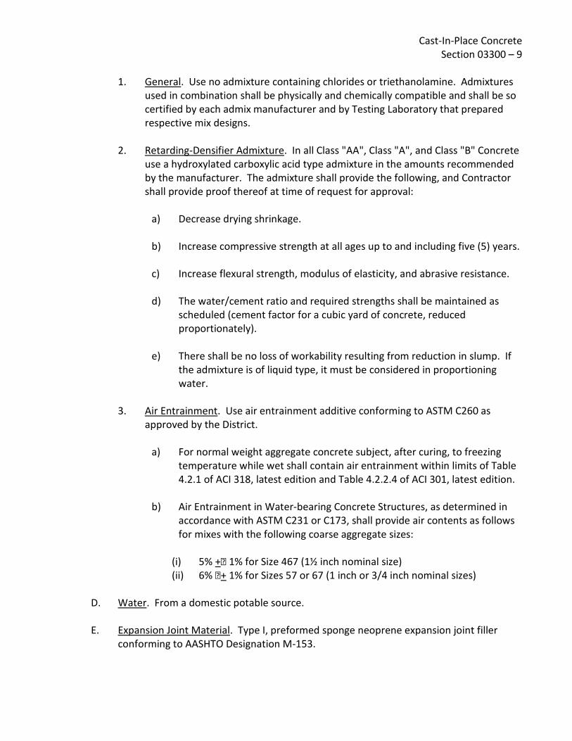
Cast-In-Place Concrete Section 03300 – 9
1. General. Use no admixture containing chlorides or triethanolamine. Admixtures
used in combination shall be physically and chemically compatible and shall be so certified by each admix manufacturer and by Testing Laboratory that prepared respective mix designs.
2. Retarding-Densifier Admixture. In all Class "AA", Class "A", and Class "B" Concrete use a hydroxylated carboxylic acid type admixture in the amounts recommended by the manufacturer. The admixture shall provide the following, and Contractor shall provide proof thereof at time of request for approval:
a) Decrease drying shrinkage.
b) Increase compressive strength at all ages up to and including five (5) years.
c) Increase flexural strength, modulus of elasticity, and abrasive resistance.
d) The water/cement ratio and required strengths shall be maintained as scheduled (cement factor for a cubic yard of concrete, reduced proportionately).
e) There shall be no loss of workability resulting from reduction in slump. If
the admixture is of liquid type, it must be considered in proportioning water.
3. Air Entrainment. Use air entrainment additive conforming to ASTM C260 as
approved by the District.
a) For normal weight aggregate concrete subject, after curing, to freezing temperature while wet shall contain air entrainment within limits of Table 4.2.1 of ACI 318, latest edition and Table 4.2.2.4 of ACI 301, latest edition.
b) Air Entrainment in Water-bearing Concrete Structures, as determined in
accordance with ASTM C231 or C173, shall provide air contents as follows for mixes with the following coarse aggregate sizes:
(i) 5% + 1% for Size 467 (1½ inch nominal size) (ii) 6% + 1% for Sizes 57 or 67 (1 inch or 3/4 inch nominal sizes)
D. Water. From a domestic potable source.
E. Expansion Joint Material. Type I, preformed sponge neoprene expansion joint filler
conforming to AASHTO Designation M-153.

Cast-In-Place Concrete Section 03300 – 10
F. Bituminous Mastic. For fills at specific designated locations (such as fills at precast panel lift-eyes and dowel hole fills in precast concrete panels) use either Hot-Applied Type Joint Sealer, ASTM D1190 or Cold-Applied Type Joint Sealant, ASTM D1850. Material shall bond to concrete, prevent moisture infiltration and when set, shall be non-tracking at summer temperatures.
G. Waterstops. Waterstops shall be produced by an extrusion process in such a manner that any cross section shall be dense, homogeneous and free from porosity and other imperfections. They shall be symmetrical in cross-sectional shape and uniform along their length. The manufacturer must certify in writing that all waterstops are extruded from elastomeric polyvinyl chloride compound and that this compound shall be virgin PVC compound and not contain any scrap or reprocessed materials whatsoever. The manufacturer must also certify in writing that all waterstops meet or exceed the physical properties requirements set forth in the U.S. Corps of Engineers' CRD-C572-74 specification and include a copy of certified independent laboratory test data showing compliance. All waterstop intersections (ells, tees, crosses, etc.) shall be fabricated by the manufacturer and these shall have 2 ft. long legs to facilitate field butt splicing. Where field dimensions are encountered which will not accommodate the specified waterstop, waterstop of reduced dimension may be approved by the Engineer for a specific application.
H. Concrete Joint Sealants. For sealing joints in nonwater-bearing concrete surfaces, use materials conforming with requirements specified in Section 07920, "Sealants and Caulking". For sealing concrete joints which will be immersed or intermittently immersed in water or sewage-bearing surfaces, use: Karlee Company's "Lastex M" 100 percent solids polyurethane sealant; Mameco International's Vulkem 227, Vulkem 45, or Vulkem 245 contingent upon need for self-leveling, non-sag and atmospheric humidity at time of usage; Hunt's Seal Flex 227-U Special Reservoir Grade polyurethane sealant; or equal. 1. Primer. Use primer produced and/or recommended by sealant manufacturer.
2. Back-up Preformed Joint Filler. Use closed-cell polyethylene foam or equal
impervious, compatible, compressible foam material recommended for retaining sealant depth in expansion joints while curing. Use no bitumen or oil saturated material.

Cast-In-Place Concrete Section 03300 – 11
3. Bond Breakers. Bond breakers, where required, shall be polyethylene tape or
equal as recommended by sealant manufacturer to prevent adherence of sealant to back-up material.
I. Dry Pack Mortar. Dry pack mortar shall consist of by volume one part special cement, three parts sand and water. The special cement and sand shall be combined in the proper proportions and then thoroughly mixed with the required amount of water. The dry pack mortar shall contain only enough water to permit placing and packing and shall be mixed for the time limit as indicated by the manufacturer in advance of use. The dry pack mortar shall be placed against thoroughly wet concrete and shall be cured by water, fog spray, spray-on membranes, sisal kraft paper, or other curing method acceptable to the District.
J. Grout. Grout to be applied to the concrete surface shall consist of one part Portland Cement to three parts dry, washed sand to sufficient water to allow placement, screening, and finishing.
K. Rich Grout. Rich grout shall consist of by volume one part Portland Cement, two parts sand and water. The rich grout shall be mixed and cured in the same manner as required for dry pack mortar.
L. Neat Grout. Neat grout shall consist of Portland Cement, flyash, water and optional admixtures. Neat grout is intended to be injected under low pressure to backfill the annular space between steel casing pipes and carrier pipes.
M. Nonshrink Grout. Nonshrink grout shall be made with the following proportions:
One part Type II Portland Cement (one sack); One part Nonshrink Aggregate (100 lbs.); One part clean, well graded concrete sand (100 lbs.); Approximately 5.5 gallons of water per sack of cement 1. In all locations where the surface of the grout will be exposed to view, the
nonshrink grout shall be recessed approximately one-half inch back of the exposed surface and the recessed area filled with cement mortar grout.
N. Nonshrink Concrete. All nonshrink concrete shall contain one pound of nonshrink
aggregate per pound of water that is in excess of two gallons per sack of cement. Recess surface exposed to field as specified for nonshrink grout above.
O. Nonshrink Aggregate. Nonshrink aggregate shall be non-metallic as produced by Master Builders, an equivalent product of Sonneborn, or a product by any other manufacturer that will meet the same ASTM requirements and equal performance.

Cast-In-Place Concrete Section 03300 – 12
P. Epoxy. Epoxies for grouting, crack repair, patching, bonding or other uses shall be as follows as manufactured by Adhesive Engineering Company, Sika Chemical Company, or equal by other manufacturer. Throughout, use products of single manufacturer. 1. All epoxy mixing, surface preparation and application shall be made in
conformance with manufacturer's printed specifications, as approved by the Engineer.
2. For bonding new concrete to old concrete and for grouting metal anchors, use Sika's "Sikadur Hi-Mod", Adhesive Engineering Company's Concresive 1001-LPL, except Concresive 1170 or 1422 shall be used as recommended by manufacturer to satisfy entailed project temperature and surface moisture variations at time of application; or equal.
3. For patching concrete surfaces, making high strength epoxy concrete or grout, and grouting metal anchors, use Sika's "Sikadur Hi-Mod LV"; Adhesive Engineering Company's "Concresive 1180"; or equal.
4. For pressure injection or gravity-feed grouting, use Sika's "Hi-Mod LV"; Adhesive Engineering Company's "Concresive Structural Concrete Bonding Process System" as recommended by manufacturer and approved by Engineer; or equal.
Q. Liquid Curing Compound. Use "TLF" or "Clear 225 TU" by Hunt Process Company, Burke
"Rez-X", or equal conforming to ASTM C309 and providing no detrimental affects with deferred finishes. On surfaces within reservoirs or other concrete structures containing potable water, use nontoxic materials which are free of odor and taste. Provide supporting technical data. Floor hardener treated floors shall use materials only as recommended in writing by hardener manufacturer.
R. Sheet Curing Materials. ASTM C171, waterproof paper, polyethylene film or white burlap-polyethylene sheet, non-staining.
S. Vapor Barrier Membrane. Under interior on-grade slabs of occupied areas provide lapped and sealed vapor barrier membrane using Fortiber "Moistop", "Damproof XX" by Nicolet of California, Incorporated, or equal with manufacturer's recommended polyethylene pressure sensitive tape sealant used continuously at lapped joints, penetrations and at perimeter walls or footing surfaces. Throughout, use products and system of single manufacturer.

Cast-In-Place Concrete Section 03300 – 13
T. Gasket Seal for Manhole and Wet Well Precast Concrete Members. Provide gasket seals
at mating joint of precast concrete sections. Size gaskets to suit joint dimensions, surface conditions and to assure watertight completed installation. Seal shall consist of either compressible closed-cell neoprene rods with compatible bonding agent recommended by material manufacturer; of No. 95 extruded butyl rod and No. 2 Primer each produced by General Sealants, Incorporated, City of Industry, California; or equal non-bituminous joint sealing compressible gaskets.
U. Synthetic Sponge Rubber Filler. Synthetic rubber filler shall be an expanded closed-cell sponge rubber, manufactured from a synthetic polymer neoprene base. The material shall be No. 750.3 Ropax Road Stock as manufactured by the Presstite Division of Interchemical Corporation; Bondtex as manufactured by Rubatex Corporation; or approved equal. The size of the material shall be 25% greater in diameter than the nominal joint width. The manufacturer's instructions for surface preparation and application shall be used as a guide for installation, except that the material shall not be installed by stretching beyond its normal length.
V. Expansion Joint Filler. Bituminous fiber expansion joint filler shall be in accordance with ASTM D1751. Bituminous expansion joint material shall not be used in joints to be sealed with synthetic rubber sealing compound.
W. Concrete Expansion Bolts/Deferred Bolting Device (D.B.D.). Except as otherwise specified, where expansion bolts are called for on the Drawings, Parabolt Concrete Anchors as manufactured by the Molly Company, Kwik-Bolts as manufactured by McCulloch Industries, Incorporated, or a concrete anchor by any other manufacturer that shall meet the same Federal Specification requirements and shall equal the performance, shall be used. All bolts thus furnished and used on this project shall be manufactured of stainless steel.
2.02 CONCRETE MIXES
A. 28-Day Compressive Strength. It shall be the sole responsibility of the Contractor to mix, place, and cure concrete which shall be of 150 lb./cu.ft. nominal density and which shall attain the compressive strengths at 28 days as designated on Structural Drawings or in these specifications for use in various locations. 110695
B. Maximum Aggregate Size. Conform to Article 2.01 B.2. For Class "AA" concrete use 1½ inch maximum size aggregate unless otherwise designated; for Class "A" and Class "B" use 1 inch maximum size aggregate; for Class "C" and Class "D" use 3/4 inch maximum size aggregate. In no case shall the size of the coarse aggregate exceed 75% of the horizontal space between reinforcing bars or between reinforcing bars and forms.

Cast-In-Place Concrete Section 03300 – 14
C. Mix Designs. Conform with requirements of Article 1.04 "Concrete Mix Designs and Preliminary Tests". At least 60 days before any Class concrete is to be placed, the Contractor shall submit for approval for each proposed mix a mix design made by a Civil Engineer registered in California or a Testing Laboratory approved by the District.
1. In lieu of a submittal from the Contractor for a required mix design, upon approval
of the Engineer the following mixes may be used with a slump of 4 to 5 inches: EMWD Mix #9 (Class "A" structural concrete)
Cement: 5.5 sacks/c.y., 517 lbs./c.y. Water: 32-34 gal./c.y. Aggregate: 1985 lbs./c.y. - #3 (3/4 inch to 1 inch max.) Sand: 1359 lbs./c.y. Admixture: Master Builders: 4 1 fl. ozs./100 lbs. of cement, Pozzolith Type
300-N W.R. Grace: 5 oz/100 lbs. cement WRDA-79, or 3 oz/100 lb. cement WRDA-64 or other water-reducing admixture meeting ASTM C-494 Type A (21 fl. oz/c.y.).
Standard Specifications for Public Work Construction Class 560-C-3250 (Optional mix for Class “A” structural concrete)
Cement: 5.96 sacks/c.y., 560 lbs./c.y. Water: 38 gal./c.y Aggregate: 1478 lbs./c.y. - # 3 (3/4 inch to 1 inch max)
246 lbs./c.y. - # 4 (3/8 inch max) Sand: 1355 lbs./c.y. Admixture: Master Builders: 4 + 1 fl. ozs./100 lbs. of cement, Pozzolith Type
300-N W.R. Grace: 5 oz/100 lbs. cement WRDA-79, or 3 oz/100 lb. cement WRDA-64 or other water-reducing admixture meeting ASTM C-494 Type A (21 fl. oz/c.y.).
The combined aggregate grading shall be per Standard Specifications for Public Work Construction Section 201- 1.3.2 as shown below:
Sleve size Percent Passing
1½" 100 1" 95-100
3/4" 77-93 3/8" 50-70

Cast-In-Place Concrete Section 03300 – 15
No. 4 39-51 No. 8 31-41
No. 16 22-32 No. 30 12-22 No. 50 3-9
No. 100 0-3 No. 200 0-2
EMWD Mix #6 (Class "B" concrete)
Cement: 4.7 sacks/c.y., 441.8 lbs./c.y. Water: 30-32 gal./c.y. Aggregate: 415 lbs./c.y. - #4 (3/8 inch max.)
795 lbs./c.y. - #3 (3/4 inch to 1 inch max.) 1006 lbs./c.y. - #2 (1½ inch max.)
Sand: 1230 lbs./c.y. Admixture: Master Builders: 4 1 fl. ozs./100 lbs. of cement, Pozzolith Type
300-N W.R. Grace: 5 oz/100 lb. cement WRDA-79, or 3 oz/100 lb. cement WRDA-64 or other water-reducing admixture meeting ASTM C-494 Type A (18 fl. oz/c.y.).
Riverside County Class “B” Concrete
Cement: 5.5 sacks/c.y., 517 lbs./c.y. Water: 36.5 Gal./c.y. Course Agg. 1" x #4: 1559 lbs./c.y. Course Agg. 3/8" x #8: 226 lbs./c.y. Sand: 1434 lbs./c.y. Water Cement Ratio: 0.59 max. Slump: 4" max.
Course aggregate shall meet the grading requirements of ASTM C33. The combined aggregate grading shall be per Caltrans Standard Specification 90-3.04(1"max), as shown below:
Sleve size Percent Passing
1½" 100 1" 95-100
3/4" 55-100

Cast-In-Place Concrete Section 03300 – 16
3/8" 45-75 No. 4 35-60 No. 8 27-45
No. 16 20-35 No. 30 12-25 No. 50 5-15
No. 100 1-8 No. 200 0-4
Riverside County Class “B” Machine Laid Concrete
Cement: 5.5 sacks/c.y., 517 lbs./c.y. Water: 34.0 Gal./c.y. Course Agg. 1" x #4: 1388 lbs./c.y. Course Agg. 3/8" x #8: 295 lbs./c.y. Sand: 1589 lbs./c.y Water Cement Ratio: 0.55 max. Slump: 2" max
Course aggregate shall meet the grading requirements of ASTM C33. The combined aggregate grading shall be per Caltrans Standard Specification 90-3.04(1"max), as shown below:
Sleve size Percent Passing
1½" 100 1" 95-100
3/4" 55-100 3/8" 45-75 No. 4 35-60 No. 8 27-45
No. 16 20-35 No. 30 12-25 No. 50 5-15
No. 100 1-8 No. 200 0-4

Cast-In-Place Concrete Section 03300 – 17
EMWD Mix #10 (Class "C" concrete)
Cement: 4.5 sacks/c.y., 423 lb./c.y. Water: 32-34 gal./c.y. Aggregate: 1903 lb./c.y. Sand: 1480 lb./c.y. Admixture: None
2.03 CONCRETE MIXING Concrete shall be ready-mixed, supplied from an off-site commercial ready-mix plant approved by District, each load accompanied by a bonded weighmaster's certificate listing the quantity of each concrete ingredient, admixture quantity, water content and slump, and time of loading and departure from ready-mix plant. Also include notations to indicate equipment was checked and found to be free of contaminants prior to batching.
A. Ready-Mixed Concrete. Unless approved otherwise in advance of batching, all concrete of a single design mix for any one day's pour shall be from a single batch plant of a single supplier. Conform to ASTM C94, except materials, testing and mix design shall be as specified herein. Use transit mixers equipped with automatic devices for recording number of revolutions of drum. All applicable mixing requirements specified herein for concrete mixed at the site shall govern transit-mixed concrete and the District shall have free access to the batching plant at all times. For concrete mixed in top-loading truck mixers, each batch shall be turned not less than 40 and not more than 300 revolutions of the mixer drum at mixing speed when the fine and coarse aggregate are charged into the mixer simultaneously (cement and water may be charged separately). When the fine and coarse aggregate are charged into the mixer separately, each batch shall be turned not less than 60 and not more than 300 revolutions of the drum at mixing speeds. For concrete mixed in end-loading truck mixers, each batch shall be turned not less than 60 and not more than 300 revolutions of the mixer drum at mixing speed when the mixer is loaded in excess of 50 percent of the gross drum volume as provided hereinafter. When the mixer is loaded (not to exceed 50 percent of the gross drum volume) the provisions specified for top-loading truck mixers will apply. Truck mixers shall be loaded in accordance with manufacturer's capacity ratings, but in no case shall the volume of mixed concrete exceed 50 percent of the gross volume of the drum for top-loading mixers and 58 percent of the gross volume of the drum for end-loading truck mixers.

Cast-In-Place Concrete Section 03300 – 18
Mixing speed shall be in accordance with manufacturer's recommendations, but in no case shall the speed be less than 4 revolutions per minute or greater than a speed resulting in a peripheral velocity of the drum of 225 feet per minute. The power unit shall be equipped with a governor to insure constant speed. Each truck mixer shall be equipped with a device for counting the number of revolutions of the drum, which device shall be interlocked so as to prevent the discharge of concrete from the drum before the required number of turns. After the drum is once started, it shall be revolved continuously until it has completely discharged its batch. Water shall not be admitted to the mix until the drum has started revolving. The right is reserved to increase the required minimum number of revolutions or to decrease the designated maximum number of revolutions allowed, if necessary, to obtain satisfactory mixing, and the Contractor will not be entitled to additional compensation because of such increase or decrease.
B. Mixing Water Limitations. If water is added at the batching plant, ready-mixed concrete shall not be held in the mixer for more than one and one-half hours from the time the water is added. When temperature of concrete is 85°F or above, reduce holding time to 45 minutes. Do not deliver ready-mixed concrete to job with total specified amount of water incorporated therein. Without 2½ gallons of water per cubic yard, then incorporate in mix before concrete is discharged from mixer truck. If no water is added at the batching plant, measured quantities of water shall be added at the site and a minimum of fifteen minutes mixing given, or mixing to overcome segregation. Adding of water shall be under observation of Inspector. Each mixer truck shall arrive at the job site with its water container full. In event container is not full or concrete tests to a greater slump than specified, the load is subject to rejection.
C. Job Mixed Concrete. Contractor shall obtain the approval of the District for equipment and procedures proposed for job mixed concrete.
D. Consistency and Slump. Adjust quantity of water so concrete does not exceed maximum slumps specified when placed or specified water/cement ratio; use minimum necessary for workability required by the part of the structure being cast. Measure consistency of concrete in accordance with ASTM C143. Concrete exceeding maximum slump will be rejected. Part of Structure Maximum Slump
Footings and mass concrete not reinforced 3 inches
Slabs, and floors and reinforced footings 2 to 3 inches
Columns, walls over 8 inches thick 3 to 4 inches
Walls up to 8 inches thick 3 ½ to 4 inches
Equipment bases 3 to 5 inches

Cast-In-Place Concrete Section 03300 – 19
PART 3 - EXECUTION
3.01 PREPARATION BEFORE PLACING Remove excess water from forms before concrete is deposited. Divert any flow of water without washing over freshly deposited concrete. Remove hardened concrete, debris, and foreign materials from interior of forms and from inner surfaces of mixing and conveying equipment.
A. Forms. Prior to placing concrete, forms shall meet the requirements of Section 03150, as approved by the Engineer. Concrete to be poured on earthwork such as slabs or stairs on grade shall meet the same requirements for approval prior to pouring as above specified for the approval of forms.
B. Reinforcement. Reinforcement shall have been secured under work of Sections 03150 and 03200, and inspected and approved. Embedded metal shall be free of old mortar, oils, mill scale, and other encrustations or coatings that might reduce bond. Wheeled concrete-handling equipment shall not be wheeled over reinforcing nor shall runways be supported on reinforcing. "Break-out" bars or dowels bent for forming, for subsequent straightening prior to adjacent pour, will be allowed with bars of #5 maximum size, only where specifically called out on the Drawings, and only where kinks or breaks are not likely as a result of straightening. This does not imply approval of cold joints where none designed, or any deviation from construction joint requirements elsewhere in these specifications.
C. Wetting. Wet wood forms sufficiently to tighten up cracks. Wet other materials sufficiently to reduce suction and maintain concrete workability.
D. Earth Subgrade. Lightly dampened 24 hours in advance of concrete placing, but not muddied. Reroll as necessary for smoothness, and remove all loose materials.
E. Aggregate Fill Base. Prepare same as earth subgrade. Center 30-mil plastic sheeting or roofing cap sheet on base course under indicated waterstop joints to retain mix fines within mix and prevent their percolation into base course.

Cast-In-Place Concrete Section 03300 – 20 3.02 WATERSTOPS Heat fuse joints and connections in strict compliance with manufacturer's instructions including heating tools and devices. Waterstops shall be continuous in joints, following offsets and angles in joints until spliced to waterstops at intersecting joints, completely sealing the structure. Waterstops shall be aligned and centered in joints. Secure flanges of waterstops to reinforcing bars with 18 gage wire ties spaced maximum 18 inch center. All waterstops, splices, joints, intersections, and welds shall be tested with an approved holiday spark tester before concrete is placed. The contract drawings do not indicate every location that is to have waterstop. Waterstop shall be located in all water bearing structure walls and slabs. Waterstop shall be positioned correctly during installation and all splices in length or at intersections shall be performed by heat sealing and in accordance with manufacturer's recommendations. Waterstop joints shall conform to Drawing requirements, if requirements are shown on the Drawings, and, whether or not requirements are shown on the Drawings, shall be properly heat-spliced at ends and crosses to preserve continuity. All splicing shall be done using mitered joints. Forms for construction joints shall be constructed in such manner as to prevent injury to waterstops. Waterstops shall be securely held in position in the construction joints by wire ties. In narrow walls requiring both rebar and waterstop, the rebar shall be offset to one side and the keyway and/or waterstop shall be offset to the opposite side sufficiently to allow placement of both rebar and waterstop without contact. In order to accommodate such an offset, double curtain steel may be replaced by one properly designed larger bar upon approval by the Engineer. All in-place waterstop installations including locations and joints shall be approved by District prior to placement of concrete.
3.03 JOINTS IN CONCRETE Locate joints in concrete where indicated unless otherwise approved. Obtain approval of points of stoppage of any pour, prior to scheduling of pour.
A. Construction Joints. Unless otherwise shown, all construction joints shall be provided with suitable keyways or other keying methods. Clean and roughen contact surfaces of construction joints by removing entire surface and exposing clean aggregate solidly embedded in mortar matrix. Use mechanical chipping, sandblasting, or application of surface mortar retarder followed by washing and scrubbing with stiff broom. Cover and protect waterstops and other inserts from damage. Where construction joints are not indicated on the Drawings, provide slabs and walls with construction joints at intervals not greater than 30 feet. Starter walls shall be used unless detailed otherwise. Where utilized, starter walls shall extend a minimum of 3½ inches.

Cast-In-Place Concrete Section 03300 – 21
Where "break-out" bars are required by the contract drawings for future structure extensions, except where other methods are specifically set forth on the contract drawings a required mortar-tight enclosure of the reinforcing dowels shall be provided by installing the break-out bars in capped PVC pipe embedded 1 inch minimum into the structural concrete.
B. Expansion Joints. Provide where indicated, ½ inch width unless otherwise detailed. Except where synthetic rubber (sealant) sealed joints are shown or specified, provide expansion joint filler and joint sealer, filler head down ½ inch to 3/4 inch and sealer finished flush with surface. At synthetic rubber sealed joints, hold filler down ½ inch unless otherwise shown, ready to receive sealant. 1. Location of joints in interior slabs on grade shall be as detailed on the Drawings.
Sawed control joints shall be as approved by the Engineer
2. Control joints in exterior slabs shall be located as indicated on the Drawings, or as follows if not noted:
a) Provide bond breaker with ½ inch expansion joint material at junction of walls, bases, columns, etc.
b) Provide ½ inch expansion joints at changes in direction of slabs, or abrupt
changes in width and not greater than twenty (20) feet apart on slabs without control joints.
c) Control joints in exterior slabs shall be sealed with the specified sealer.
C. Roof and Floor Slabs. Pour slabs in alternating checkerboard fashion between indicated
construction joints, as approved. Slabs in place shall be cured as required elsewhere in these specifications a minimum of seven (7) days before adjoining slabs are cast.
D. Intermediate Screed Strips. Intermediate screed strips shall be required for all slab pours unless otherwise approved. Such approval for the omission of intermediate screeds shall be for each individual pour and no blanket approval shall be given.
E. Gasket Seals. At joints between precast concrete manhole and/or wet well units, clean mating surfaces of both members. Then within groove, place and lay continuous rod of specified compressible gasket to provide watertight installation after placement of matching tongued concrete member and compression of the gasket.
F. Joining Existing Structures. Where a construction joint to an existing structure requires a waterstop and none is found in the existing structure, Contractor shall join the old structure by chamfering the new concrete at the joint and filling the chamfer with specified epoxy sealant.

Cast-In-Place Concrete Section 03300 – 22
Where required reinforcing is not found protruding from the existing structure, required reinforcing shall be placed by drilling and placing dowels of the proper size and spacing. Where required waterstop and reinforcing is found in the existing structure, joints shall be treated as other construction joints under Articles 3.01 and 3.02.
G. Concrete for Buried Electrical. Buried electrical ducts, conduits & similar type items are to be encased in Class C red colored concrete as disignated below. Aggregate for Class C Concrete for Encasement of Electrical Conduits: 1. Graded as specified in ASTM C 33, Size Number 8. 2. Provide concrete utilizing this aggregate equal to Class C concrete in all other
respects. 3. Manufacturers: Frank D. Davis Company, Red Oxide Number 1117 or equal.
3.04 CONVEYING AND PLACING CONCRETE
A. Do not pour concrete until reinforcing steel and forms have been inspected and approved. Notify District not less than one full working day in advance of readiness for inspection of forms and reinforcing. Specific approval of individual forms by the Engineer shall be obtained before ordering of concrete. The Contractor shall give the Engineer a minimum of 24 hours notice of a scheduled concrete pour following the completion of forming. Upon inspection of the forms, reinforcing, waterstop placement, etc., the Engineer will immediately issue a written approval to pour concrete showing approval of the scheduled pour or disapproval. In the event of disapproval, the Engineer will show the Contractor the specific deficiencies, for correction within the 24 hour period prior to the scheduled pour. Upon notification by the Contractor of correction of deficiencies and reinspection and approval by the Engineer, the pour may proceed as scheduled. In the event required corrections are not made, or are not approved, the disapproval of the pour shall stand and the pour shall not proceed as scheduled, but shall be rescheduled. Any concrete not in accordance with these specifications, out of line, level, or plumb; or showing cracks, rock pockets, voids, stalls, honeycombing, exposure of reinforcing, or any other damage which will be detrimental to the work will be considered defective and must be corrected and replaced as directed by the Engineer at no additional cost to the District. Any concrete work that is not formed as indicated; is not true within 1/250th of the span; is not true to intended alignment; is not plumb or level where so intended; is not true to intended grades and levels; has voids or honeycombs that have been cut, resurfaced or filled, unless under the direction of the Engineer; has any

Cast-In-Place Concrete Section 03300 – 23
sawdust, shavings, wood or embedded debris; or does not fully conform to the contract provisions, shall be deemed to be defective and shall be removed from the site. 1. Handle or pump no concrete utilizing aluminum equipment.
2. Delivery tickets shall show the following:
a) Batch number.
b) Mix by compressive strength with maximum aggregate size.
c) Types and amount of admixtures included.
d) Air content.
e) Slump.
f) Time of loading and discharge.
g) Amount of water put in at batch plant.
h) Location in the work.
i) Specification class of concrete.
j) Date of delivery.
3. If any water is added at the job site, it shall be approved by the Engineer and the
delivery ticket noted as to the amount of water added. One copy of each delivery ticket shall be submitted daily to the Engineer.
B. Weather. Do not place concrete during rain or freezing weather unless approved
measures are taken to prevent damage to concrete. Concrete placed during periods of dry winds, low humidity, high temperatures, and other conditions causing rapid drying shall be initially cured with a fine fog spray of water applied immediately after finishing and maintained until final curing operations are started. Also under hot weather conditions, steps shall be taken to reduce concrete temperatures and water evaporation by proper attention to ingredients, production methods, handling, placing, protection, and curing.

Cast-In-Place Concrete Section 03300 – 24
1. Preventative measures taken for concrete placement during hot or cold weather shall be approved by the Engineer. There shall be no placing of concrete when ambient temperatures are below 35°F or above 100°F, or when such will be the case within 24 hours of the pour. Any concrete previously placed shall be protected from freezing.
C. Conveying. Do not drop concrete from its point of release at mixer, hopper, tremies, or
conveyances more than 6 feet, nor through reinforcing bars in a manner that causes segregation. Provide form windows, tremies, elephant trunks, and equivalent devices as required. The use of chutes for conveying or depositing concrete is not allowed except for small isolated portions of the work and only with prior approval. Deposit concrete directly into conveyances and from conveyances to final points of repose. Deposit concrete so that the surface is kept level throughout, a minimum being permitted to flow from one portion to another.
D. Placing Concrete. Concrete shall be placed and compacted within 90 minutes after water is first added to the mix, and no concrete shall be placed after there is evidence of initial set. This placing time shall be reduced to 45 minutes when the temperature of the concrete is 85°F or above. Retempering of concrete is not allowed. 1. Horizontal Construction Joints. Horizontal surfaces of previously placed and
hardened concrete shall be wet and covered with a 6 inch thick layer of concrete of the design mix with 50% of coarse aggregate omitted just before balance of concrete is placed.
2. Lifts. Pour concrete into forms immediately after mixing in a manner that will prevent separation of ingredients. Except as interrupted by joints, all formed concrete shall be placed in continuous, approximately horizontal layers, the depths of which generally shall not exceed 18 inches.
a) Walls and Slabs. In order to minimize the effects of shrinkage, concrete
shall be placed in units bounded by construction joints. The placing of units shall be done by placing alternate units in a manner such that each unit placed shall have cured at least 7 days for hydraulic structures and 3 days for all other structures before the contiguous unit or units are placed. The exception is corner sections of vertical walls, which shall not be placed until the adjacent wall panels have cured at least 14 days for hydraulic structures and 4 days for all other structures.
b) Beams and Slabs. Pouring of all beams and slabs must be continuous and monolithic with the floor system where so shown on the Drawings. At least two (2) hours must elapse after depositing concrete in walls or columns before pouring beams, etc. supported thereon.

Cast-In-Place Concrete Section 03300 – 25
3. Pumping Concrete. No increase in the specified slumps will be allowed and
required water/cement ratios shall be maintained for concrete pumping. Aluminum tubes are not acceptable for conveying concrete. Equipment shall be capable of maintaining the specified pour rates. Conform with requirements of ACI 304.2R-96, except as more stringent requirements are specified herein. Minimum conduit (tube) diameter shall be 4 inches.
4. Pour Rates.
a) Vertical Elements. Place concrete in lifts as specified at a rate that does not overstress forms nor allows the top of a lift to begin to harden before the next lift is placed. Cold joints are not acceptable.
b) Slabs. Place concrete at a rate that ensures all deposits are joined to
concrete that is still plastic and within 10 minutes of the previous pour. Concrete adjoining alternate slabs shall not be placed until the adjoining concrete has cured as required elsewhere in this specification for at least seven days unless otherwise approved by the Engineer.
5. Field Tests. During the progress of construction, the District will have tests made
to determine whether the concrete, as being produced, complies with the standards of quality specified herein. These tests will be made in accordance with ASTM C3l and ASTM C39. Each test will consist of a minimum of four cylinders, and the District, at his discretion, may take such tests as frequently as necessary to prove the quality of the concrete. In no case shall less than one test be made of each day's pour or of each 50 yards of concrete. The Contractor shall furnish the concrete for such tests but the remaining testing expense will be borne by the District. Specimens will be cured under job conditions. For all concrete, the standard age of test will be 28 days, but the 7-day test may be used provided that the relation between the 7 and 28 strengths of the concrete is established by tests for the materials and proportions used. Slump tests will be in accordance with ASTM Cl43. Enforcement of Strength Requirement. Concrete is expected to reach a higher compressive strength than that indicated as minimum compressive strength. At least the specified minimum cement shall be used, and more cement shall be used, if necessary, to meet all minimum and maximum requirements shown in the table. Failure to meet these conditions shall be considered failure of the concrete.

Cast-In-Place Concrete Section 03300 – 26
One test shall consist of the results of testing three (3) standard specimens in accordance with ASTM C3l and C39, except that if one specimen in a test shows manifest evidence of improper sampling, molding, or testing, it shall be discarded and the remaining two strengths averaged. Should more than one specimen presenting a given test show defects due to improper sampling, molding, or testing, the entire test shall be discarded. If the concrete fails to meet the specifications in the preceding paragraph, the District shall have the right to ask for additional curing of the affected portion followed by cores taken in accordance with ASTM C42 all at the Contractor's expense. If the additional curing does not bring the average of three cores taken in the affected area to at least the strength specified, the District may require strengthening of the affected portions of the structures by means of additional concrete or steel, or he may require replacement of these affected portions, all at the Contractor's expense. Core tests for below-strength concrete shall be paid for by the Contractor even though such core tests indicate the concrete has obtained the required minimum compressive strength.
E. Compaction. Effective compaction shall be obtained by vibration, agitation, spading,
and rodding until the concrete is free from voids, air bubbles, or rock pockets. Vibrators shall not be used to transport concrete within the forms. No less than one spare vibrator for each two vibrators in use on a pour, each in good working condition shall be kept on the job during pours. One experienced workman shall be assigned to the operation of each vibrator as his only duty. Operations not deemed to be satisfactory by the District shall be immediately corrected. 1. Vibration. All concrete, with the exception of concrete slabs 4 inches or less in
depth, shall be compacted with high frequency, internal mechanical vibrating equipment supplemented by hand spading and tamping. Concrete slabs 4 inches or less in depth shall be consolidated by wood or metal grid tampers, spading and settling with a heavy leveling straight edge. Carefully vibrate concrete around waterstops and ensure the waterstops are not bent or damaged.
a) Vibrators. Vibrators shall be designed to operate with vibratory element submerged in the concrete, and shall have a frequency of not less than 7,000 impulses per minute when submerged. The vibrating equipment shall be adequate at all times in number of units and power of each unit to consolidate the concrete to the maximum practicable density so that it is free from air pockets, honeycomb, entrapped air and so it closes snugly against all surfaces of forms and embedded items.

Cast-In-Place Concrete Section 03300 – 27
b) Operation of Vibrators. Do not allow vibrators to contact forms or
reinforcing. In vibrating a freshly placed layer of concrete, the vibrator shall be inserted vertically through the preceding layers that are still completely plastic and slowly withdrawn, producing the maximum obtainable density in the concrete without creating voids. Under no circumstances shall the vibrator enter or disturb concrete that has stiffened or partially set. The interval of vibrator placing shall not exceed two-thirds the effective visible vibration diameter of the submerged vibrator. Avoid excessive vibration that causes concrete segregation or causes an inordinant amount of entrained air to move to the face of the forms, which shall be causes for rejection of the concrete pour.
c) Re-Vibration of Retarded Concrete. Concrete containing retarding
admixture for structural walls and columns shall be placed by a schedule that allows each layer of concrete to be in place and compacted for at least 30 minutes before the next layer of concrete is placed. Bleed water on the surface of the concrete shall be removed before additional concrete is placed and the concrete in place re-vibrated before the next lift is placed. At tops of walls and columns concrete containing excess water or fine aggregate caused by vibration shall be removed while plastic, and the space filled with compacted concrete of the correct proportions, vibrated in place.
F. Slabs. Set screeds at maximum 8 foot centers, as approved, and verify correct
elevations with instrument level, and consideration for any camber in the form. Compact and tamp concrete to bring 3/8 inch mortar to surface, and wood float to straightedges and screeds. Make finished surfaces level or sloped as detailed, with maximum deviation of 1/4 inch from 10 feet straightedge for exposed finishes, and there shall be no low spots to impound water. Do not use steel or plastic floats of any kind of initial floating operations. Unless otherwise specified, do not apply hereinafter specified finishes until surface water disappears and surface is sufficiently hardened. Remove all bleed water and laitance as it appears.
G. Tolerances 1. Forms, sleeves, and inserts shall be set, and concrete shall be cast, to the lines and
grades indicated on the plans and as detailed in these specifications. The maximum deviation from true line and grade shall not exceed the tolerances listed in the following table.

Cast-In-Place Concrete Section 03300 – 28
Item Maximum Tolerance Sleeves and inserts +1/8 inch -1/8 inch
Projected ends of anchor bolts +1/4 inch -0.0 inch
Anchor bolt setting +1/16 inch -1/16 inch 2. Formed surface tolerances for concrete shall meet requirements for ACI surface
classes as follows, unless otherwise specified herein or in the Special Provisions. Class "A". Exposed interior and exterior concrete to be coated or painted.
Abrupt irregularities must meet a modified requirement of 1/16 inch maximum.*
Class "B". Coarse textured concrete intended to receive plaster, stucco or
wainscoting. Class "C". Exposed interior and exterior concrete not requiring coating or
painting. Class "D". Permanently concealed surfaces below permanent ground level
or operating water surface.
Permitted Irregularities in Formed Surfaces Checked with a 5-foot Template
Type of Irregularity
ACI Surface Tolerance Class of Surface
A B C D
Gradual 1/8 inch 1/4 inch ½ inch 1 inch
Abrupt *1/16 inch 1/4 inch 1/4 inch 1 inch
3. Deviation in alignment of slabs or walls shall not exceed a rate of l/8 inch in l0 feet
within the tolerances specified.
4. Slabs shall be uniformly sloped to drain.
5. Regardless of the tolerances listed herein, it shall be the responsibility of the Contractor to limit deviations in line and grade to tolerances which will permit proper installation and operation of mechanical equipment and piping.

Cast-In-Place Concrete Section 03300 – 29
3.05 CURING FORMED CONCRETE Maintain forms containing concrete in a thoroughly wet condition until forms are removed. Maintain all concrete in a continuously moist condition for not less than 7 consecutive days after pouring (14 days on projects subject to Federal Wage Determination). Keep concrete moist with fine fog spray until protected by curing materials. Use water curing method, specified liquid membrane-forming compound, or concrete curing paper or mats, all subject to approval for each specific use. Vertical surfaces shall not be cured by sprinkling method unless specifically approved by the Engineer.
3.06 PLACING GROUT
A. Grout all steel bearing plates, columns, and other structural parts set to hardened concrete using nonshrink grout. Use an approved premixed grout, adding only water in the amount recommended by the manufacturer.
B. Generally, use driest practicable mix and pack into place so no voids remain between steel and the supporting concrete.
C. When necessary, use sufficient water to produce a flowable mixture, and pour, first forming sand dams to retain the grout until partially set. When sufficient set is attained, remove dams and pack grout to refusal on all four sides, to eliminate voids; fill any resulting edge voids with drier mix.
D. In all locations where the surface of the grout will be exposed to view or in an area of high humidity, nonshrink grout shall be recessed to approximately one-half inch back of the exposed surface and the recessed area filled with cement mortar grout.
3.07 ANCHORS, SLEEVES, STAIR NOSINGS, ETC
A. Install in forms, in accordance with layout information provided by their suppliers, all necessary anchors, anchorage inserts, sleeves, slots, etc., required for fastening or passing the work of other Sections; also all such surface items as edge angles, manhole frames and other castings, trench cover frames or gratings, access panels, expansion joint covers, stair nosings, etc., having anchorage features requiring that they be installed before concrete is placed.
B. All such items shall be accurately located, carefully plumbed and leveled, securely fastened in place so that alignment and level will not be disturbed during concreting, and protected from damage until concreting is completed.
C. Provide all openings and chases in concrete, shown on the Drawings or as otherwise required.
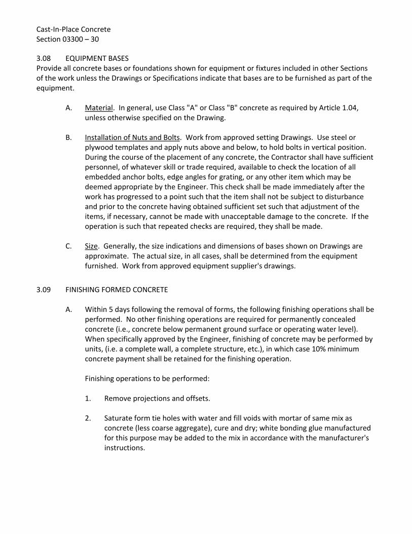
Cast-In-Place Concrete Section 03300 – 30 3.08 EQUIPMENT BASES Provide all concrete bases or foundations shown for equipment or fixtures included in other Sections of the work unless the Drawings or Specifications indicate that bases are to be furnished as part of the equipment.
A. Material. In general, use Class "A" or Class "B" concrete as required by Article 1.04, unless otherwise specified on the Drawing.
B. Installation of Nuts and Bolts. Work from approved setting Drawings. Use steel or plywood templates and apply nuts above and below, to hold bolts in vertical position. During the course of the placement of any concrete, the Contractor shall have sufficient personnel, of whatever skill or trade required, available to check the location of all embedded anchor bolts, edge angles for grating, or any other item which may be deemed appropriate by the Engineer. This check shall be made immediately after the work has progressed to a point such that the item shall not be subject to disturbance and prior to the concrete having obtained sufficient set such that adjustment of the items, if necessary, cannot be made with unacceptable damage to the concrete. If the operation is such that repeated checks are required, they shall be made.
C. Size. Generally, the size indications and dimensions of bases shown on Drawings are approximate. The actual size, in all cases, shall be determined from the equipment furnished. Work from approved equipment supplier's drawings.
3.09 FINISHING FORMED CONCRETE
A. Within 5 days following the removal of forms, the following finishing operations shall be performed. No other finishing operations are required for permanently concealed concrete (i.e., concrete below permanent ground surface or operating water level). When specifically approved by the Engineer, finishing of concrete may be performed by units, (i.e. a complete wall, a complete structure, etc.), in which case 10% minimum concrete payment shall be retained for the finishing operation. Finishing operations to be performed:
1. Remove projections and offsets.
2. Saturate form tie holes with water and fill voids with mortar of same mix as
concrete (less coarse aggregate), cure and dry; white bonding glue manufactured for this purpose may be added to the mix in accordance with the manufacturer's instructions.

Cast-In-Place Concrete Section 03300 – 31
3. Patch all damaged areas due to spalling, voids, rock pockets and bleeding of
cement (generally caused by form leaks) with mortar over a concrete adhesive bonding agent manufactured for this purpose and applied in accordance with the manufacturer's instructions. Cut out all rock pockets to sound concrete, edges square to the surface and back beveled, and patch with tempered mortar applied over an approved epoxy concrete adhesive. Large areas (as determined by the Engineer), and all other damaged areas over ½ inch in depth shall be repaired similarly. Other damaged areas less than ½ inch in depth shall be similarly repaired, but an approved white concrete bonding agent may be used in place of epoxy concrete adhesive.
4. Finish patches flush with adjoining surfaces and cure the same as the original concrete. Attention is directed to the need for properly curing the repair patches, and for utilizing the proper bonding agent for a given situation (i.e., below operating water level). Information regarding the manufacturer's recommended use shall be furnished to the Engineer for his evaluation. Pursuant to the specifications, all concrete must be cured for seven (7) days after pouring or patching, including sacked concrete, except concrete sacked after 7 days following pouring or patching needs no further curing.
5. Small air holes may be considered those which would be covered over by sacking, and need not be repaired on external walls being waterproofed or other areas not required to be sacked under the specifications. Air holes larger than this shall be considered voids. Minor cement paste leaks are those not exposing aggregate and which can be covered over by sacking, and should be treated similarly to small air holes. Anything larger shall be considered a rock pocket or a bleed hole, depending upon the condition. Some small bleed holes may, at the discretion of the Engineer, not need to be chipped out, but may be merely sandblasted to sound concrete prior to patching.

Cast-In-Place Concrete Section 03300 – 32
B. All exposed interior and exterior formed concrete (i.e., concrete not permanently concealed from direct visible exposure under facility operating conditions, including gallery and equipment room walls and ceilings), and all concrete to be coated in the finished structure shall, in addition to the foregoing, be Brush-Off Blast Cleaned (SSPC-SP7-63) to open all paste and air holes and to remove curing compound and dust. It shall then be rubbed with cement of consistent color and burlap and/or with brick and water to eliminate pockets and produce reasonable smooth surfaces suitable for painting. A reasonable smooth surface shall be defined as a surface with no projections or form marks greater than 1/16 of an inch and no indentations after finishing. Chamfers and fillets shall be made straight and true, and uniform. Concrete to be temporarily concealed until facility is expanded shall be considered exposed concrete.
C. All formed concrete within water bearing structures and not subject to Item 3.09.B shall be brush-off cleaned (SSPC-SP7) to open all paste and air holes and to remove curing compound and dust. Alternatively, a high-pressure water spray may be used if the method is demonstrated by the Contractor to be effective in removing the curing compound and opens all defects. The high-pressure water spray alternative must be approved by the Inspector.
All defects greater than ¼ inch in depth are to be filled. Prep defects by applying by brush, a neat cement/water/latex bonding agent paste. Defects shall then be filled by immediately applying and scrubbing in a thick 60-grit sand/cement mortar paste with a sponge rubber float. The mortar is to fill defects only and all excess material shall be cut from the surface with the edge of a steel trowel. Apply curing compound to all repairs.
3.10 FINISHING SLABS AND FLATWORK As specified above, initially compact, bring 3/8 inch mortar to surface and float surfaces. Finished surfaces shall be "puddle-free" and level or sloped as indicated to above specified maximum deviation limits. Surfaces which are not within these limits shall be removed and replaced at no additional cost to District; patching is not acceptable. Keep surface moist with fine fog spray of water to prevent drying during finishing operations and until curing media is applied. Dusting with cement or sand during finishing operations is not permitted.
A. Precautions. Slabs have not been designed for heavy construction loads. Contractor shall repair or replace damaged slabs resulting from his use of heavy equipment or loadings as directed by the Engineer.
B. Rough Slabs. Broom surfaces of slab after initial set of concrete leaving coarse aggregate slightly exposed. Apply on following areas and surfaces: 1. Concrete to receive deferred concrete, grout or mortar.

Cast-In-Place Concrete Section 03300 – 33
2. Tops of footings for masonry.
C. Monolithic Trowel Finish. For all floor, slab, and flatwork surfaces not otherwise indicated or specified. After surface water disappears and floated surface is sufficiently hardened, steel trowel and retrowel to smooth surface. After concrete has set enough to ring trowel, retrowel to a smooth uniform finish free of trowel marks or other blemishes. Avoid excessive troweling that produces burnished areas.
D. Steel Float Finish. Same as monolithic trowel finish, except omit second retroweling. Apply on following area and surfaces: 1. Apply on floor slab surfaces in water-bearing structures.
2. Areas scheduled to receive resilient floor coverings.
E. Swirl Non-Slip Finish. Prepare same as steel float finish, then perform final troweling with circular motion and slightly lift trowel to produce uniform swirl (sweat trowel) non-slip finishes matching sample selected by District from Contractor-prepared 2-foot square sample panels. Unless otherwise specified, provide uniform coarse texture on exterior walking surfaces.
F. Wood Float Finish. Float to screeds. When ready, finish with wood floats to a uniformly textured surface. Apply on following areas and surfaces: 1. Exterior walking surfaces exceeding 1:10 slope.
G. Floor Hardener Application 1. Floor hardener shall be applied by dust-on method to all interior exposed concrete
floors, and to other specifically designated floors using specified materials and rates of coverage.
2. Prior to application, the Contractor shall consult with the manufacturer's field representative in regard to application of floor hardener under prevailing job conditions.
3. Float and trowel floor hardener into the surface of freshly floated concrete floors shall be in strict accordance with the manufacturer's printed instructions.
4. Cure as work progresses using method conforming to hardener manufacturer's printed directions.

Cast-In-Place Concrete Section 03300 – 34 3.11 CURING SLABS AND FLATWORK Apply curing media as soon as feasible after finishing operations without marring surfaces, and in any case on same day. Keep surfaces moist until curing is applied. Upon approval of liquid compounds, apply in strict accordance with material manufacturer's published application rates; apply two (2) spray coats, second coat sprayed at right angle direction from first coat. Carefully mask and protect adjoining surfaces where compound is used.
A. Curing Period and Protection. Maintain curing materials in proper sealed condition for minimum of 7 days (14 days on projects subject to Federal Wage Determination) after application. Keep traffic on curing surfaces to the minimum possible, and completely off liquid compound cured surfaces. Immediately restore any damaged or defective curing media.
B. Restriction. Do no use liquid membrane-forming curing compound within water-bearing structures, or on surfaces to receive deferred concrete or masonry, or on surfaces to receive fluid-applied protective coatings or waterproofing.
C. Liquid Membrane-Forming Curing Compound. Upon approval, and except as restricted above, use liquid curing compound for all slabs, floors, and flatwork. On slabs having floor hardener treatment, cure such slabs in strict conformance with printed recommendations of floor hardener manufacturer. Other special precautions may be required if concrete is exposed to freezing or otherwise adverse weather conditions during the curing period.
D. Sheet Curing. Use concrete curing sheet material on surfaces where liquid curing is not permitted, and on all joints sealed with pressure sensitive tape; immediately repair any tears during curing period. Verify that surfaces remain damp for full curing period; if necessary or directed, lift sheeting and wet surfaces with clean water, and replace sheeting.
E. Water Curing. Alternate to either liquid curing compound or sheet curing method where approved. Keep concrete continuously wet by ponding, sprinklers, or equivalent for entire curing period.
3.12 FORMED STAIRS AND TREADS Stair nosings are required on all stairs. Accurately place cast abrasive nosings and screed tread surface flush and level. Cut riser back as indicated. At exterior and wet interior locations, apply coarse textured swirl non-slip abrasive finish on surface of treads and landings. Strip protective tape from the nosings on completion of cement finishing operations.

Cast-In-Place Concrete Section 03300 – 35
3.13 CHAMFERS AND FILLETS Unless otherwise shown on the drawings or directed by the Engineer, exposed edges of formed concrete structure shall be provided with a 45°, 3/4 inch x 3/4 inch chamfer. Where fillets are shown on the drawings, they shall be formed with a 45°, 3/4 inch x 3/4 inch form chamfer, formed with a 3/8 inch radius form, or tooled with a 3/4 inch radius rounding tool. Where project is an expansion of an existing facility, chamfer selected shall be compatible with chamfer of existing facility.
3.14 JOINTS WITH SEALANT Sandblast joints to clean sound concrete, using oil-free air to provide surfaces free of oil, foreign materials, and moisture. Mix and place primer, and sealant in accordance with manufacturer's printed instructions. Install foam backing in joints so sealant depth is between one-half and two-thirds of joint width. Isolate backing from sealant using a bond breaker such as polyethylene tape, aluminum foil, or wax paper.
A. Manufacturer's Supervision. A technical representative of the sealant manufacturer shall be present at the time sealant operations are started to supervise and approve preparation, sealant mixing, and sealant applications procedures and applicators. The representative shall make frequent visits to the site to ensure that sealant installations conform to the manufacturer's instructions, and shall issue a written report to District covering each visit.
B. Crack Sealing. Before and after backfilling of the tanks, all cracks over 0.01 inch wide in concrete surfaces of tanks and other water-containing structures shall be cutout as detailed and the groove filled with backing, primer, and sealant.
C. Joint Sealer. Unless specified otherwise, IGAS type joint sealer shall be used where joint depth is equal to or greater than twice the joint width. Colma type joint sealer shall be used where the depth to width ratio is less than 2:1.
D. Sealant. All sealant shall be placed in strict accordance with the manufacturer's printed specifications by a firm specializing in this type of work for not less than five (5) years, or by the Contractor under direct supervision of the manufacturer's representative.
E. Sealant Locations. All locations where sealant is placed must be cleaned by sandblasting and be free from oil, foreign materials, and moisture. Lower surfaces of joints shall be isolated with a bond breaker such as polyethylene, wax paper, aluminum foil or polyethylene tape.

Cast-In-Place Concrete Section 03300 – 36 3.15 INSTALLATION OF PIPELINES THROUGH CONCRETE STRUCTURES
A. Whenever a pipeline or any material terminates or extends at or through a structural wall or sump, the Contractor shall install in advance of pouring the concrete the fitting or special casting required for the particular installation. Otherwise, prepare and submit shop/erection drawings of other installation methods and obtain approvals in advance of commencement of work.
B. Whenever any run of pipe is installed per approved shop/erection drawings subsequent to placing of concrete, the Contractor shall accurately position the opening in the concrete for such pipelines. Unless otherwise required, all pipes penetrating fluid containing or earth-supporting portions of the structure shall be ring flanged. 1. Opening shall be of sufficient size to permit a perfect final alignment of pipelines
and fittings without deflection of any part and to allow adequate space for satisfactory packing where pipe passes through wall to insure watertightness around openings so formed.
2. The boxes or cores shall be provided with continuous keyways to hold the filling material in place and to insure a watertight joint.
3. Boxes or cores shall be filled with nonshrink grout or nonshrink concrete.
3.16 FIELD QUALITY CONTROL
A. Concrete Tests. At District's expense, District's selected Testing Laboratory shall perform the concrete tests: 1. Compression Tests. Make one set of at least four standard test cylinders from
each day's placing and each 50 cubic yards, or fraction thereof, for each class of concrete. Date cylinder, number and tab, indicating location in structure from which sample was taken. Indicate slump test result of sample. Do not make more than one set of test cylinders from any one location or batch of concrete.
2. Test Cylinders. Provide for testing by District or Testing Laboratory to take test cylinders at the job in accordance with ASTM C31. Test specimens in accordance with ASTM C39 at the age of 7 and 28 days. Contractor shall furnish labor and assistance for casting test cylinders, and shall furnish moist curing cabinets, as required, conforming to ASTM C31 at the site.

Cast-In-Place Concrete Section 03300 – 37
3. Core Tests. Should strength of concrete, as indicated by tests, fall below required
minimum, then additional tests of concrete which the unsatisfactory samples represent may be required by District. Testing Laboratory will make such test in accordance with ASTM C42. Contractor shall fill the holes made by cutting cores with dry pack concrete. Tests for below-strength concrete shall be paid for by the Contractor even though such tests indicate the concrete has obtained the required minimum compressive strength.
4. Air Content. At time that compression test cylinders are cast, test a sample of the same concrete for air content in accordance with ASTM C231.
3.17 WATERTIGHTNESS OF CONCRETE STRUCTURES
A. All concrete structures designed to contain or convey fluid shall be tested for watertightness by the Contractor by filling with water to levels approximating what will be attained during operation and measuring the drop in level due to leakage, if any. These tests shall be made under the direction of the District, and if necessary, the tests shall be repeated until watertightness is insured.
B. Rate of filling shall be limited to minimize shock-effect to new concrete c+onstruction. Water shall be held under each condition long enough to satisfy the District that the structures are watertight. Structures shall be free of internal or external water leakage.
C. The total loss of water-level in any basin or flume shall not exceed 1/2 inch depth in 24 hours. Leakage shall be located and stopped and the structure again tested until this requirement is met. If the structure does not meet the test, the Contractor shall repair or replace at his own expense, such part of the work as may be necessary to secure the desired results, as approved by the District.
D. Regardless of the rate of leakage, there shall be no visible leakage from any concrete structure.
3.18 ALTERATIONS AND REWORK Existing concrete surfaces to receive new concrete shall be heavily sandblasted to expose coarse aggregate and produce clean coarse textured surface. Such prepared surfaces shall be coated with epoxy bonding compound immediately prior to placing concrete. The compound shall be an approved equivalent to Sika Chemical Company's "Sikastix Adhesive", Hunt Process Company's "HB Series Epoxy Mortar", or equal of type, mix and application in strict accordance with manufacturer's printed recommendations and directions for various conditions.

Cast-In-Place Concrete Section 03300 – 38 3.19 REMOVAL OF EXISTING CONCRETE, MASONRY, OR GROUT Contractor shall utilize necessary equipment and techniques to remove specified concrete, masonry, and grout without damaging or affecting the integrity of the remaining material. Upon removal to the specified limits, any exposed reinforcing steel, anchor bolts, or other embedded items, shall be chipped, cut, or ground to not less than 2 inch depth from the remaining surface. Remaining holes and cavities shall be repaired as follows:
A. Perimeter of holes or cavities shall be cut back to trueline a minimum depth of 1/2 inch. Edges shall be feathered.
B. Surfaces of holes or cavities shall be roughened by mechanical means to provide an aggregate-fractured surface with a 1/4 inch (minimum) profile and cleaned of a loose material and dust.
C. A bonding agent shall be applied to all hole or cavity surfaces immediately prior to filling with repair mortar. The bonding agent shall be Sika Corporation's "Armatec 110", Hunt Process Company's "HB Series Epoxy Mortar", or equal.
D. Holes and cavities shall be filled with Sika Corporation's "MonoTop 611" mortar, or equal. For placement greater than 3 inches in depth, 3/8 inch aggregate shall be added to the mortar to create a repair concrete. Vertical surfaces shall be formed. Horizontal surfaces, including slab overlays, shall be hand trolled and finished to match adjacent concrete.
E. Bonding agent and repair mortar/concrete shall be mixed and installed in strict accordance with the manufacturer's printed instructions.
3.20 QUALITY OF WORK Concrete work which is found to be in any way defective or out of tolerance may be ordered by the District to be removed and replaced. Should this occur, all costs shall be paid by the Contractor.
END OF SECTION 03300
Rev: 09/02/08
SPECIFICATIONS - DETAILED PROVISIONS Section 04220 - Concrete Masonry Units
C O N T E N T S
PART 1 - GENERAL ............................................................................................................................. 1
1.01 DESCRIPTION ............................................................................................................................. 1 1.02 QUALITY ASSURANCE ................................................................................................................ 2 1.03 SUBMITTALS .............................................................................................................................. 2 1.04 PROTECTION ............................................................................................................................. 2 1.05 COORDINATION ........................................................................................................................ 2 1.06 SCAFFOLDING ............................................................................................................................ 3 1.07 DELIVERY AND STORAGE........................................................................................................... 3
PART 2 - PRODUCTS .......................................................................................................................... 3 2.01 MATERIALS ................................................................................................................................ 3 2.02 MORTAR AND GROUT ............................................................................................................... 5
PART 3 - EXECUTION ......................................................................................................................... 6 3.01 EXISTING CONDITIONS .............................................................................................................. 6 3.02 PLACING REINFORCING ............................................................................................................. 7 3.03 INSTALLATION, GENERAL .......................................................................................................... 7 3.04 INSTALLATION OF REINFORCED CONCRETE MASONRY UNIT (CMU) ..................................... 10 3.05 CLEAN-UP AND REWORK ........................................................................................................ 12

[PAGE LEFT INTENTIONALLY BLANK]

Concrete Masonry Units Section 04220 – 1
SECTION 04220 CONCRETE MASONRY UNITS
PART 1 - GENERAL
1.01 DESCRIPTION Provide concrete masonry unit work, complete as indicated, specified and required.
A. Work Included in This Section. Principal items are:
1. Concrete block masonry.
2. Installing reinforcing steel in masonry.
3. Grout and mortar for masonry.
4. Shoring, bracing and scaffolding incidental to work of this Section.
5. Smooth surface parget coat of cement mortar on surfaces of masonry knockout
(filler) panels.
6. Setting and incorporating into masonry all bolts, anchors, inserts, and ledgers.
7. Building in of frames, vents, pipes, conduits, and inserts.
8. Pointing, cleaning and protection.
9. Treatment of masonry surfaces.
B. Related Work Not Included in This Section. 1. Concrete footings with dowels for masonry.
2. Furnishing and delivery of steel bar reinforcing.
3. Furnishing items for embedment with setting instructions and layout drawings.
C. Waterproofing and/or Water Repellent of Masonry. Masonry surfaces shall be clean
and dry before applying surface treatment and shall be free of any efflorescence. Masonry surfaces shall cure for a minimum of 10 days prior to surface treatment application.

Concrete Masonry Units Section 04220 – 2 1.02 QUALITY ASSURANCE Unless otherwise specified, all work specified herein and as shown on the drawings shall conform to the applicable requirements of the Uniform Building Code. Arrange for furnishing test specimens as may be required.
A. Inspection. All masonry work shall be performed under the continuous inspection of the
District's Inspector or qualified masonry inspector as selected and approved by District. Costs of retests and/or reinspection because of nonconforming materials or workmanship shall be borne by the Contractor.
1.03 SUBMITTALS
A. Stock Samples. Submit photos of each type of exposed block. Include in each set, the full range of exposed texture to be expected in the completed work. District's review will be for texture only. Compliance with all other requirements is the exclusive responsibility of the Contractor.
B. Erection of Bond Beams. Prior to delivery of any items of the work specified herein, the
Contractor shall submit to the District's representative for approval, shop drawings showing his proposed method of erecting the bond beams at the heads of all openings, including crimped metal or wire inserts in the masonry soaps (half-width blocks), scaffolding, mortar joints, bar reinforcement, grouting, and joint finish.
C. Compressive Tests. The Contractor shall have compressive tests made of grout to be
used in the work and shall submit certificates from a recognized, independent testing laboratory showing that the masonry units, mortar, and grout meet the minimum compressive strengths specified.
D. Sample Panel. Sample masonry panels shall not be required unless required by the
contract plans or the Special Conditions.
1.04 PROTECTION Provide and be responsible for protection and repair of adjacent surfaces and areas which may be damaged as a result of work of this Section. Protect work performed hereunder until completion and final acceptance of project by District. Repair or replace all damaged or defective work to original specified condition, at no additional cost to the District.
1.05 COORDINATION Coordinate and cooperate with other trades whose items require embedment into masonry to avoid cutting and patching. Accurately install items in masonry as work progresses and in accordance with approved shop/layout or erection drawings. Cooperate with all other trades in the layout of work.

Concrete Masonry Units Section 04220 – 3
1.06 SCAFFOLDING Provide safe and adequate scaffolding, planking, ladders and/or ramps conforming with all applicable CAL/OSHA State of California Construction Safety Orders, and requirements of other governing authorities.
1.07 DELIVERY AND STORAGE
A. Masonry Units. Masonry units shall be carefully stacked prior to use and shall be properly protected from weather by cover or inside storage. All units shall be handled with reasonable care to prevent marring or damaging of faces, edges and corners of units.
B. Lime and Cement. Deliver in original packages and store on platforms above ground,
protected against moisture. C. Aggregates. Store on platforms so as to exclude dirt. D. Reinforcing Steel. Store above ground to prevent bending or rusting. E. Materials for Treatment of Masonry Surfaces. The contractor shall deliver sealers,
coatings, waterproofing, or other surface treatment materials to the site in their original, unopened containers with the manufacturer's labels intact, describing contents and manufacturer. Stored materials shall be kept covered and precautions shall be taken for the prevention of fire. Empty containers and soiled or oily rags shall be removed from the site at the end of each day's work
PART 2 - PRODUCTS
2.01 MATERIALS Materials shall conform to the following requirements.
A. Masonry Units. Grade N-1, natural color, hollow load bearing units conforming to ASTM
C-90. Provide in nominal concrete block sizes designated on Drawings with units of standard manufacture as approved by the District, having uniform smooth surfaces. Other block types, where required, shall be of sizes and textures, or combinations of block texturing, as called for on the Drawings.
1. All units shall conform to the requirements of the Quality Control Standards of the
Concrete Masonry Association.

Concrete Masonry Units Section 04220 – 4
2. Masonry units shall have cured for not less than 28 days when placed in the
structure.
3. All masonry units shall have a maximum linear shrinkage of 0.06 of one percent (1%) from the saturated to the oven-dry condition, when tested in accordance with the methods set forth in the Quality Control Standards of the Concrete Masonry Association.
4. Crimped metal or wire inserts shall be provided in soaps (half-width blocks) at wall
opening heads to provide mechanical attachment of the soaps to the bond beam.
B. Cement. Portland Cement conforming to ASTM C-150, Type I or Type II, low alkali. Use NO plastic cement.
C. Lime Putty. Made from quick lime conforming to ASTM C-5, and completely slaked
before using. D. Hydrated Lime. Conforming to ASTM C-207, Type S. E. Aggregates. Aggregates for mortar and grout shall be clean, sharp, and well graded, and
free from injurious amounts of dust, lumps, shale, alkali, surface coatings and organic matter.
1. For mortar, aggregates shall conform to ASTM C-144, except not less than five
percent (5%) shall pass No. 100 sieve. 2. For grout, aggregates shall conform to ASTM C-404. 3. For pea gravel, aggregates shall conform with ASTM C-33 graded with not more
than five percent (5%) passing a No. 8 sieve and one hundred percent (100%) passing a 3/4 inch sieve.
F. Shrinkage Reducing Admixture. In all grout for reinforced masonry work, use Sika
Chemical Company's "Suconem GA Grout Aid", Type II, "Red Label", or approved equal meeting ASTM requirements for grout for reinforced masonry.
G. Water. Clean and from potable source. H. Tie-Wire. For installation of reinforcing bars, use wire conforming to ASTM A-82, double
annealed wire gage No. 18 or heavier.

Concrete Masonry Units Section 04220 – 5
I. Mastic Sealant Around Pipes. Where called for on the plans, mastic sealant around
pipes through masonry walls, shall consist of a blend of refined asphalts, resins and plasticizing compounds, reinforced with long-fiber asbestos. Primer shall consist of Gilsonite and petroleum asphalts and resinous plasticizers and shall be supplied by manufacturer of mastic sealant.
The mastic shall not lose more than one percent (1%) of its original weight when a 1/4-inch thick sample is maintained at a temperature of 200 degrees Fahrenheit for 4 hours. It shall not become fluid at temperatures of less than 300 degrees Fahrenheit or brittle at temperatures above minus 10 degrees Fahrenheit. The mastic shall not sag in a vertical concrete joint ½-inch wide, 1-inch deep, and at least 6-inches long at a temperature of 180 degrees Fahrenheit for a 24-hour period. It shall not rupture or lose bond when it is installed between concrete blocks and, at a temperature of 50 degrees Fahrenheit, is extended to one hundred and fifty percent (150%) of its original length at a rate up to 0.15 inch per hour. Mastic sealant shall be compatible with fillers and shall be pressure grade, unless otherwise approved by the Engineer.
J. Waterproofing. Below grade surfaces shall be waterproofed with a pre-fabricated self-
adhering sheet type waterproofing membrane. The membrane shall consist of a multi-layer high-strength polymer film that is coated with a rubberized asphalt adhesive. The system shall be MFW SubSeal 40 by Chargar Corporation; or equal.
K. Water Repellent. Above grade surfaces shall have a water repellent that is a
silane/siloxane, volatile organic compound compliant, and free of silicone oils or paraffin wax. The spray equipment shall be high-volume, low-pressure, airless with a maximum of 60 psi. The pump shall be non-atomizing and able to flow at a rate of 1 to 1-1/2 gallons per minute. The system shall be Rainguard, Blok-Lok; Prosoco Inc.; or equal.
2.02 MORTAR AND GROUT
A. Mortar Mix. Type S per U.B.C. Table 21-A.
Mortar shall be freshly prepared and uniformly mixed in the ratio by volumes of one part cement, one-quarter part lime putty or hydrated lime, three and three-fourth parts sand and shall conform to ASTM C-270. Add one pint of admixture per sack of cement. The color of the mortar shall match the color of the concrete masonry units. Mortar coloring pigments shall be pure, non-fading oxides. Mortar shall attain a minimum compressive strength of 1800 psi at 28 days.

Concrete Masonry Units Section 04220 – 6
B. Grout Mix. Per U.B.C. Section 2103.4, and the addition of specified shrinkage-reducing
admixture in strict conformance with printed recommendations of the manufacturer, as approved by the District.
Grout shall be of fluid consistency and mixed in the ratio by volumes, one part cement, three parts sand, two parts pea gravel. Add one pint of admixture per sack of cement. Grout shall attain a minimum compressive strength of 2000 psi at 28 days.
C. Mixing. Water (eighty percent (80%) of total), sand and lime shall be placed in the mixer
in that order, and mixed for at least one minute, after which the cement and remaining water shall be added and mixed as long as necessary for a uniform mass, but not less than 10 minutes.
D. Water. Sufficient water shall be used with the grout mix to cause it to flow into all joints
without separation of ingredients. Slump of the grout mix shall be approximately 9 - 10 inches depending on temperature and humidity conditions. Only paddle type mixers of at least one sack capacity shall be used. Mortar and grout awaiting the mason's use shall be turned and remixed as required to maintain a workable mix.
1. Grout for pumping shall be as fluid as possible without segregation of the
constituent parts, and shall have not less than seven (7) sacks of cement in each cubic yard of grout. Mix shall be approved in advance by the District.
2. Grout shall not be handled or pumped utilizing aluminum equipment.
E. Retempering. Retempering of grout will not be permitted. Retempering of mortar shall
be done only by adding water into a basin made with the mortar and the mortar carefully worked into the water. Retempering by dashing water over the mortar will not be permitted. Any mortar, or grout, which is unused within one hour after the initial mixing, shall be removed from the work. Mortar shall be mixed and maintained on the boards to a slump of 3/4 inch, plus or minus 1/4 inch, using a truncated cone 4 inches to 2 inches, 6 inches high.
PART 3 - EXECUTION
3.01 EXISTING CONDITIONS Masonry Installer must examine the areas and conditions under which masonry work is to be installed and notify the Contractor in writing of conditions detrimental to the proper and timely completion of the work. Do not proceed with the work in an effected area until satisfactory conditions have been corrected in a manner acceptable to the Masonry Installer.

Concrete Masonry Units Section 04220 – 7
3.02 PLACING REINFORCING
A. General. Clean free of loose rust, scale, and other materials which will reduce bond to mortar or grout. Do not use reinforcing bars with kinks or bends not shown on drawings or final shop drawings, or bars with reduced cross section due to excessive rusting or other causes.
B. Positioning. Position reinforcing accurately at the spacing shown. Support and secure
vertical bars against displacement. Horizontal reinforcing may be placed as the masonry work progresses. Where vertical bars are shown in close proximity, provide a clear distance between bars of not less than the nominal bar diameter or 1 inch, whichever is greater.
C. Splicing. Splice reinforcing bars where shown; do not splice at other points unless
acceptable to the Engineer. Provide lapped splices unless otherwise shown. In splicing vertical bars or attaching to dowels, lap ends, place in contact and wire tie.
1. Provide not less than minimum lap shown, or if not shown, lap a minimum of 50
bar diameters. Separate by one bar diameter or wire bars together. 2. Hold vertical bars in position at top and bottom and at intermediate intervals not
exceeding 192 diameters of the reinforcement. D. Foundation Dowels.
1. Simple Footing. When a foundation dowel does not line up with the vertical core to be reinforced, it shall not be bent over but shall be grouted into a core in direct vertical alignment, even though it is in a cell adjacent to the vertical wall reinforcing.
2. Column Footing. When a foundation dowel does not line up with the vertical core
to be reinforced, it may extend into a core in direct vertical alignment or it may be cut off flush with the footing; and the specified bar shall be dowelled into the footing and anchored in place in accordance with the requirements for dowels of Section 03200.
3.03 INSTALLATION, GENERAL
A. General. Clean top surface of concrete foundation of dirt, projections, and laitance before starting masonry construction. Blocks shall be dry when laid. Clean masonry units of all dust and dirt before laying. Discard cracked and chipped blocks. Erect work plumb, level, and true to line with all corners and angles square.

Concrete Masonry Units Section 04220 – 8
B. Layout. Lay out walls in advance for accurate spacing of exposed bond patterns with uniform joint widths, and to properly locate openings, returns and offsets. Avoid the use of less-than-half-size units at corners, jambs and wherever possible at other locations.
C. Lay-up. Lay-up walls plumb and true with courses level, accurately spaced and
coordinated with other work. Units shall be cut accurately to fit all penetrations, and all holes shall be neatly patched. Where cutting is necessary, all cuts shall be neat and true.
D. Joints. The starting joint on foundations shall be laid with full mortar coverage on the
bed joint, except that the area where grout occurs shall be free of mortar so that grout will contact the foundation. Joints shall be straight, clean, and uniform in thickness. Unless otherwise specified or detailed on the plans, the horizontal and vertical mortar joints shall be 3/8 inch thick with full mortar coverage on cells to be filled. Block joints exposed to view in completed structure shall be tooled with a round bar to produce a dense, slightly concave surface well bonded to the block edges. Cut joints flush for masonry which will be permanently concealed or covered by other materials. Rake out mortar wherever joints are to receive caulking or sealant. Joints which are not tight at time of tooling, shall be raked out, pointed and then tooled.
Textured block joints shall be raked to uniform depth and tooled with flat pointing tool. Jointing and tooling shall be done when the mortar is partially set but still sufficiently plastic to bond. Jointing tools to be of high grade tool steel that will not blacken mortar joints when joints are rubbed to produce a dense, hard finish. Vertical head joints shall be buttered well for a thickness at least equal to the face shell of the unit and shall be shoved tightly so that the mortar bonds well to both units. Joints shall be solidly filled from the face of the block to at least the depth of the face shell.
E. Bond Pattern. Lay masonry units in one-half (½) running bond with vertical joints in each course centered on units in courses above and below, unless otherwise shown. Bond and interlock each course at corners and intersections. Use special-shaped units where shown, and as required for corners, jambs, sash, control joints, lintels, bond beams and other special conditions.
F. Care. Extreme care shall be taken to prevent visible grout or mortar stains. Masonry
units shall be sound, dry, clean and free of cracks and chips when placed in structure. Wetting the units shall not be permitted, except when hot, dry weather causes the units to be warm to the touch, and then the surface only may be wetted with a light fog spray.

Concrete Masonry Units Section 04220 – 9
G. Removal of Units. Remove masonry units disturbed after laying; clean and relay in fresh
mortar. Do not pound corners at jambs to fit stretcher units which have been set in position. If adjustments are required, remove masonry units, clean off mortar, and reset in fresh water. Masonry units with imperfect jointing, nail holes, chipped edges or corners, or other defects shall be corrected, for approval of the Engineer, or the units shall be replaced.
H. Clean-outs. Clean-out openings shall be provided at bottoms of cells to be filled at each lift or pour of grout where such lift or grout pour is in excess of four feet in height. Overhanging mortar or other obstructions or debris shall be removed from such cells. The clean-outs shall be sealed before grouting, after inspection.
I. Stops. Stop masonry work by racking back one-half (½) masonry unit length in each course; do not tooth. Stop grout pours four (4) inches back of rack ends and as further specified at top of pours. Prior to resuming masonry work, remove loose units and unbounded mortar, clean exposed surfaces of set masonry and, if specified to be wetted, wet units lightly.
J. Mason's Iron Work
1. Contractor shall furnish, set, and build into the masonry, all iron work necessary for the masonry construction, and which is enclosed in the masonry.
2. Contractor shall set and build into the masonry all items which are furnished and
located by other trades, or indicated on the Drawings, such as bolts and sleeves for securing the work of such other trades, metal attachments, sleeves, inserts, and similar items. Setting shall consist of the bedding, or setting in mortar or dry pack, of all items to be set.
3. Contractor shall build into the masonry all items furnished, located, and set by
others such as door frames, vents, conduit, pipes, and the like. Building into masonry shall consist of filling-in with mortar or grout around all items to be built into masonry, including hollow metal door frames. All such items shall be set and built-in so that there will be no voids anywhere, and so that the items are installed rigid, solid, and held accurately and securely in place.
4. Contractor shall be responsible for the accurate placement of all mason's iron
work. Anchors shall be fully and solidly grouted in place. Unless otherwise noted, embedment shall be not less than two-thirds of the wall thickness.

Concrete Masonry Units Section 04220 – 10
K. Temporary Form work
1. Provide Form work and shores as required for temporary support of reinforced masonry elements. Design, erect, support, brace and maintain Form work. No formwork or temporary supports shall be attached to the masonry except as specifically permitted by the District.
2. Construct formwork to conform to shape, line and dimensions shown. Make
sufficiently tight to prevent leakage of mortar, grout, or concrete (if any). Brace, tie and support, as required, to maintain position and shape during construction and curing of reinforced masonry.
3. Do not remove forms and shores until reinforced masonry member has hardened
sufficiently to carry its own weight and all other reasonable temporary loads that may be placed on it during construction.
3.04 INSTALLATION OF REINFORCED CONCRETE MASONRY UNIT (CMU)
A. General. Lay CMU units with full-face shell mortar beds. Fill vertical head joints (end joints between units) solidly with mortar from face of unit to a distance behind face equal to not less than the thickness of longitudinal face shells. Solidly bed crosswebs of starting courses in mortar. Maintain head and bed joint widths shown, or if not shown, provide 3/8 inch joints.
B. Walls
1. Maintain vertical continuity of core or cell cavities, which are to be reinforced and grouted, to provide minimum clear dimensions shown and to provide minimum clearance and grout coverage for vertical reinforcing bars. Keep cavities free of mortar. Solidly bed webs in mortar where adjacent to reinforced cores or cells.
2. Where horizontal reinforced beams (bond beams) are shown, use special units or
modify regular units to allow for placement of continuous horizontal reinforcing bars. Place small mesh expanded metal lath or wire screening in mortar joints under bond beam courses over cores or cells of non-reinforced vertical cells, or provide units with solid bottoms.
C. Grouting
1. Place vertical reinforcing prior to laying of concrete block. Extend above elevation of maximum pour height as required to allow for splicing.

Concrete Masonry Units Section 04220 – 11
2. Lay block to maximum pour height. Do not exceed 4 foot height or if bond beam
occurs below 4 foot height, stop pour at course below bond beam. High lift grouting may be used at Contractor's option, as approved and in accordance with Code.
3. Reinforcing steel shall be secured in place and inspected before grouting starts.
Mortar dropping should be kept out of the grout space. All vertical cells shall have vertical alignment to maintain a continuous unobstructed cell area not less than 2 inches by 3 inches. All cells shall be solidly filled with grout.
4. Pout grout using container with spout or by chute. Rod or vibrate grout during
placing. Place grout continuously; do not interrupt pouring of grout for more than one hour. Terminate grout pours 1½ inches below top course of pour.
5. Bond Beams. Stop grout in vertical cells 1½ inches below bond beam course.
Place horizontal reinforcing in bond beam; lap at corners and intersections as shown. Place grout in bond beam course before filling vertical cores above bond beam.
D. Cleaning and Protection
1. Protect all adjoining work from mortar and grout. 2. Concrete scum, mortar and grout stains on the wall shall be removed
immediately, and stains on surfaces to remain exposed shall be sandblasted from corner to corner of wall surface to obtain clean uniform appearance, at no additional cost to the District.
3. After the wall is constructed, it should not be saturated with water for curing or
any other purposes. 4. In areas where the atmosphere is dry, the masonry wall shall have its surface
dampened with a very light fog spray during a curing period for the mortar of three (3) days.
E. Parget coating of masonry knockout (filler) panels shall be cement mortar applied with a
smooth surface.

Concrete Masonry Units Section 04220 – 12
3.05 CLEAN-UP AND REWORK At the conclusion of the masonry work, the masonry contractor shall clean all masonry as required in these specifications, remove scaffolding and equipment used in the work, and remove all debris, refuse, and surplus masonry material, and remove them from the premises.
END OF SECTION 04220

Rev: 08/92
SPECIFICATIONS - DETAILED PROVISIONS Section 07920 - Sealants and Caulking
C O N T E N T S
PART 1 - GENERAL ............................................................................................................................. 1
1.01 DESCRIPTION ............................................................................................................................. 1 1.02 SUBMITTALS .............................................................................................................................. 1 1.03 WARRANTY................................................................................................................................ 2
PART 2 - PRODUCTS .......................................................................................................................... 2 2.01 MATERIALS ................................................................................................................................ 2
PART 3 - EXECUTION ......................................................................................................................... 3 3.01 GENERAL ................................................................................................................................... 3 3.02 PREPARATION ........................................................................................................................... 3 3.03 APPLICATION ............................................................................................................................. 4 3.04 CLEAN-UP AND PROTECTION .................................................................................................... 5 3.05 QUALITY CONTROL .................................................................................................................... 5


Sealants and Caulking Section 07920 – 1
SECTION 07920 SEALANTS AND CAULKING
PART 1 - GENERAL
1.01 DESCRIPTION Requirements specified in Conditions of the Contract and Division 1 form a part of this Section. Provide all sealant and caulking work, complete as indicated, specified and required.
A. Work Included in This Section. Principal items are:
1. This Specification is intended to be general in scope as to locations of caulking and
sealants. Contractor shall examine all Drawings and Details thoroughly and familiarize himself with the extent of the caulking and sealing involved. Only a complete and absolutely watertight and weathertight job will be accepted.
2. Additional information pertaining to sealing and/or caulking will be found in the various specific trade sections and shall be coordinated with the work of this Section.
B. Related Work Not in This Section. Concrete Work, Masonry Work, Doors and Frames,
Painting, Gypsum Drywall, Weatherstripping and Sound Sealing integral to manufactured items, and caulking required for piping, conduit or other mechanical or electrical work.
1.02 SUBMITTALS Prior to purchase or delivery of materials, submit the following, and obtain District acceptance.
A. Samples and Technical Data 1. Submit technical data by all manufacturers of proposed materials.
2. Submit material manufacturers' printed preparation and application instructions
to District and furnish copies to all trades concerned.
B. Shop Drawings and Mock-Ups. When requested, submit the following in accordance with these specifications: 1. Full-size details indicating all the necessary components for each type of joint to
be sealed.

Sealants and Caulking Section 07920 – 2
2. Observed field conditions and measurements. Mock-up units or test sections shall be also scheduled after receiving written approval of shop drawings by the District.
1.03 WARRANTY Contractor shall fully guarantee all materials and workmanship under this Section for a period of three (3) years from the date of final acceptance of the structure against all defects in both workmanship and materials and he shall promptly correct and/or replace such faulty work if so notified, at no additional cost to the District.
PART 2 - PRODUCTS
2.01 MATERIALS
A. Delivery. Deliver sealant and caulking compounds in unopened factory labeled containers; labels bearing statement of conformance to standards specified for each material; and bearing manufacturer's name and product designation.
B. Colors. As selected to match adjoining surfaces. Special colors may be required.
C. Sealant Compounds. Materials shall conform to Fed. Spec. TT-S-00227E(3) for multi-component sealant, or to Fed. Spec. TT-S-00230C(2) for single component sealant. Properties and adhesion of 1-part sealants shall be equal to 2-part materials. Sealants shall be Type I or Type II, as applicable. Sealants shall be limited to acceptable compounds compositions which are polysulfide, polyurethane, and silicone. For metal buildings, use Class "A" sealants, and for other locations, use Class "B" sealants each conforming with above referenced Federal Specifications or with ASTM C-920 like characteristics. Above grade sealants shall be resistant to ultra violet deteriorations. 1. For joints in water-bearing surfaces, use only polyurethane sealants certified and
approved by manufacturer for continuous or intermittent submergence in water or sewage.
2. Silicone type sealant shall be used only on above grade joints which are not subject to vehicular or pedestrian traffic.
3. Acoustical Sealant. Where designated or required at interior and acoustic partitions, use: "Acoustical Sealant" produced by USG, Tremco, or equal products.
4. For Traffic (Vehicular or Pedestrian) Horizontal Sealant Joints. Sealant shall be MAMECO International's No. 45, or equal. Provide with Shore "A" Hardness Range of 25-35.

Sealants and Caulking Section 07920 – 3
D. Primer, where required, shall be used as recommended in writing by the sealant manufacturer. Primer shall have been tested for non-staining characteristics and durability on samples of actual surfaces to be sealed.
E. Back-up Materials and Preformed Joint Fillers. Use non-staining material, compatible with sealant and primer, and of a resilient nature, such as closed cell polyethylene rod, or elastomeric tubing or rod (neoprene, butyl, or EDPM). Materials impregnated with oil, bitumen, or similar shall not be used. Size and shape shall be as indicated by joint details in Drawings and shall be as recommended by sealant manufacturer in writing. Sealant shall not adhere to back-up material.
F. Bond Breakers, where required, shall be polyethylene tape, aluminum foil or other material as recommended by sealant manufacturer in writing.
PART 3 - EXECUTION
3.01 GENERAL
A. Perform work of this Section by material manufacturer's approved applicator in strict conformance with manufacturer's printed instructions, or perform such operations under direct supervision of qualified representative of material manufacturer.
B. Applicator shall examine all surfaces and report to the General Contractor all conditions not acceptable.
3.02 PREPARATION
A. Thoroughly clean all joints, removing all foreign matter such as dust, oil, grease, water, surface dirt, frost and old caulking materials. Sealant must be applied to the base surface. Previously applied paint or primer must be entirely removed.
B. Porous materials such as concrete masonry or stone should be cleaned where necessary by grinding, blast-cleaning, mechanical abrading, acid washing or combination of these methods to provide a clean, sound base surface for sealant adhesion. 1. Laitance shall be removed by acid washing, grinding, or mechanical abrading.
2. Form oils shall be removed by blast-cleaning.

Sealants and Caulking Section 07920 – 4
3. Loose particles present or resulting from grinding, abrading or blast-cleaning shall be removed by blowing out joints with oil-free compressed air (or vacuuming) prior to application of primer or sealant.
C. Non-porous surfaces, such as metal and glass, shall be cleaned either mechanically or
chemically. Protective coatings such as methacrylate lacquer on metallic surfaces shall be removed by a solvent that leaves no residue. Solvent shall be used with clean cloths or lintless paper towels. Do not allow solvent to air dry without wiping. Wipe dry with clean, dry cloth, or lintless paper towels.
D. Joint areas to be protected with masking tape or strippable films shall be cleaned before application of tape or film.
E. All joints to receive sealant shall be as indicated on shop or Project Drawings. Do not seal joints until they are in compliance with drawings or are acceptable to the Engineer. 1. Joints to receive sealant shall be a minimum of 1/4 inch wide by 1/4 inch deep,
unless otherwise approved.
2. For joints in concrete, masonry, or stone: depth of the sealant may be equal to the width of joints up to 1/2 inch wide. For joints 1/2 inch to 1 inch wide: depth shall be 1/2 inch. For expansion and other joints, 1 to 2 inches wide: depth shall be no greater than 1/2 the applied sealant width. For joints exceeding 2 inches (5 cm) in width: depth shall be as directed by sealant manufacturer.
3. For joints in metal, glass, and other non-porous surfaces: sealant depth shall be a minimum of 1/2 the applied sealant width, and shall in no case exceed the applied sealant width.
F. Joints to receive sealant, back-up material or pre-formed joint filler shall be cleaned out,
raked to full width and depth as required by Applicator.
G. Joints shall be of sufficient width and depth to accommodate specified back-up material or pre-formed joint filler and sealant.
3.03 APPLICATION
A. Install back-up material or joint filler, of type and size specified, at proper depth to provide sealant dimensions as detailed. Back-up material shall be of suitable size and shape; and compressed 25-50 percent to fit joints as required. Sealant shall not be applied without back-up material and/or bond breaker strip. When using back-up tubes avoid lengthwise stretching. Tube or rod shall not be twisted or braided.
B. Apply masking tape, where required, in continuous strips in alignment with joint edge.

Sealants and Caulking Section 07920 – 5
C. Prime surfaces, where required, with primer as recommended by sealant manufacturer.
D. Follow sealant manufacturer's instruction regarding mixing (if required), surface preparation, priming, and application procedure.
E. Apply sealant under pressure with hand or power actuated gun or other appropriate means. Gun shall have nozzle of proper size and provide sufficient pressure to completely fill joints as designed. All joint surfaces shall be tooled to provide the contour as indicated on Drawings. When tooling joints, use tooling solution recommended by manufacturer. Remove masking tape immediately after joints have been tooled. 1. For sealant application when air temperature is below forty degrees (40o)
Fahrenheit (four degrees (4o) Centigrade), consult sealant manufacturer for recommendations.
3.04 CLEAN-UP AND PROTECTION Clean adjacent surfaces of sealant as work progresses. Use solvent or cleaning agent as recommended by sealant manufacturer. All finished work shall be left in a neat, clean condition.
3.05 QUALITY CONTROL The sealant joints shall be uniformly smooth, free of wrinkles, flush with adjacent surfaces and absolutely watertight. Adjacent surfaces which have been soiled by the application of the sealing compound shall be wiped clean and be left neat. The work will be judged defective due to the sealant's hardening, cracking, crumbling, melting, shrinking, leaking, or running.
END OF SECTION 07920

Sealants and Caulking Section 07920 – 6
[PAGE LEFT INTENTIONALLY BLANK]

Rev: 05/15
SPECIFICATIONS - DETAILED PROVISIONS Section 08711 - Locksets and Hardware
C O N T E N T S
PART 1 - GENERAL ............................................................................................................................. 1
1.01 MATERIAL SELECTION ............................................................................................................... 1 1.02 LOCK UNIFORMITY .................................................................................................................... 1
PART 2 - PRODUCTS .......................................................................................................................... 1 2.01 LOCKSETS .................................................................................................................................. 1 2.02 LOCK STRIKES ............................................................................................................................ 1 2.03 DOOR SHOES ............................................................................................................................. 2 2.04 THRESHOLD ............................................................................................................................... 2 2.05 PANIC BARS ............................................................................................................................... 2


Locksets and Hardware Section 08711 – 1
SECTION 08711 LOCKSETS AND HARDWARE
PART 1 - GENERAL
1.01 MATERIAL SELECTION Stainless steel shall be selected for use in conjunction with sewage facilities; steel (not stainless steel) shall be selected for all other uses.
1.02 LOCK UNIFORMITY All locksets, latchsets, padlocks, cylinders, and component parts as specified hereinafter, shall be compatible with District key system.
PART 2 - PRODUCTS
2.01 LOCKSETS Manufacturer shall be Schlage, L Series, Heavy Duty Mortise locks with 06 Lever Design. Cylinders: Number of Pins: 6 pin, “F” keyway, “O” bitted. Cases: Steel, cylindrical Mortise or rim cylinder. Interior Parts: Non-corrosive with non-plastic, non-die-cast, non-aluminum mechanisms. Accessibility to Key-in-knob Type Cylinders: Not requiring removal of lockset from door. Plugs: Extruded brass bar material fully round without flattened areas. Cores: Single cork, non-removable and no control keys.
2.02 LOCK STRIKES Except as otherwise specified, lock strikes shall be Schlage, boxed with lock material and shall match lockset.

Locksets and Hardware Section 08711 – 2
2.03 DOOR SHOES Except as otherwise specified, door shoes shall be PEMKO 216A extruded aluminum for 1-3/4 inch doors.
2.04 THRESHOLD Unless otherwise specified, thresholds shall be PEMKO 218A.
2.05 PANIC BARS Panic bars shall be installed on all facility doors, no exceptions. They shall be UL labeled, touch bar exit devices capable of opening a door even when locked. Panic bars shall be provided with mortise lock devices and auxiliary bolt for deadlocking, and shall be constructed of corrosion-resistant hardware. Panic bars shall be manufactured by Von Duprin, Inc., Sargent, or approved equal.
END OF SECTION 08711

Rev: 04/16/14
SPECIFICATIONS - DETAILED PROVISIONS Section 09900 - Painting and Protective Coatings
C O N T E N T S
PART 1 - GENERAL ....................................................................................................................................... 1 1.01 SCOPE ................................................................................................................................................ 1 1.02 Warranty ............................................................................................................................................ 2 1.03 CONTRACTOR ...................................................................................................................................... 3 1.04 DEFINITIONS ....................................................................................................................................... 4 1.05 HOURS OF WORK ................................................................................................................................. 4 1.06 PRE-JOB CONFERENCE .......................................................................................................................... 4 1.07 QUALITY ASSURANCE............................................................................................................................ 5 1.08 SAFETY AND HEALTH REQUIREMENTS ...................................................................................................... 5 1.09 REFERENCE SPECIFICATIONS AND STANDARDS .......................................................................................... 8 1.10 COMPLIANCE WITH ENVIRONMENTAL REGULATORY REQUIREMENTS ......................................................... 11 1.11 SUBMITTALS ..................................................................................................................................... 11 1.12 PROTECTION OF WORK ....................................................................................................................... 12 PART 2 - PRODUCTS .................................................................................................................................. 13 2.01 GENERAL .......................................................................................................................................... 13 2.02 PAINT AND COATING MATERIALS .......................................................................................................... 14 2.03 SERVICE CONDITION A ........................................................................................................................ 15 2.04 SERVICE CONDITION B ........................................................................................................................ 15 2.05 SERVICE CONDITION C ........................................................................................................................ 16 2.06 SERVICE CONDITION D ........................................................................................................................ 17 2.07 SERVICE CONDITION E ........................................................................................................................ 19 2.08 SERVICE CONDITION F......................................................................................................................... 21 2.09 SERVICE CONDITION G ........................................................................................................................ 22 2.10 SERVICE CONDITION H ........................................................................................................................ 22 2.11 SERVICE CONDITION I ......................................................................................................................... 23 2.12 ARCHITECTURAL PAINT FINISHES .......................................................................................................... 26 2.13 MISCELLANEOUS COATINGS ................................................................................................................. 33 PART 3 - EXECUTION ................................................................................................................................. 33 3.01 GENERAL .......................................................................................................................................... 33 3.02 QUALITY CONTROL ............................................................................................................................. 35 3.03 SURFACE PREPARATION, GENERAL - INDUSTRIAL ..................................................................................... 36 3.04 SURFACE PREPARATION, GENERAL - ARCHITECTURAL ............................................................................... 38 3.05 APPLICATION, GENERAL ...................................................................................................................... 38 3.06 APPLICATION, SPECIFIC - ARCHITECTURAL .............................................................................................. 40 3.07 COLOR IDENTIFICATION ...................................................................................................................... 42 3.08 STENCIL IDENTIFICATION ..................................................................................................................... 42 3.09 APPLICATION, SPECIFIC - INDUSTRIAL .................................................................................................... 43 3.10 FINAL TESTING OF INDUSTRIAL COATING ............................................................................................... 43 3.11 CLEAN-UP ......................................................................................................................................... 45 3.12 OMISSIONS ....................................................................................................................................... 45 3.13 COLOR CODE SCHEDULE....................................................................................................................... 45


Painting and Protective Coatings Section 09900 – 1
SECTION 09900 PAINTING AND PROTECTIVE COATINGS
PART 1 - GENERAL
1.01 SCOPE
A. Requirements of Conditions of Contract and Division 1 apply to this Section. Provide all labor, materials, apparatus, scaffolding, and all appurtenant work in connection with painting and protective coatings, complete as indicated, specified and required.
B. Work included in this section. Principal items include:
1. All exposed piping, conduits, ducts and other metal surfaces, interior and exterior,
except as hereinafter specifically excluded.
2. All submerged and intermittently submerged metal surfaces, except stainless steel.
3. All structural and miscellaneous steel, including tanks.
4. The interior of wet wells, headworks, manholes, junction structures, transition stations and similar structures.
5. Exterior above-ground concrete and concrete block as specified and shown on the Drawings.
6. The interior and exterior of structures as specified in the Painting Schedule and shown on the Drawings.
7. Equipment furnished with and without factory finished surfaces.
8. Equipment on which factory applied finishes have been marred, abraded, scratched, nicked, or otherwise damaged.
9. Exterior and interior concrete, concrete unit masonry, cement plaster, doors, frames, sheet metal surfaces and other architectural work as specified and shown on the Drawings.
10. Protective coating of submerged and intermittently submerged concrete and masonry surfaces, except portion of such surfaces designated to receive waterproofing.

Painting and Protective Coatings Section 09900 – 2
11. Recoating of existing interior and exterior painted surfaces from architectural break where damaged or altered in performance of Work of this General Contract.
C. Related Work Not Included in This Section. The following surfaces, in general, shall not
be painted: 1. Concrete surfaces subject to pedestrian or vehicular traffic except as herein
specified.
2. Plastic surfaces and fiberglass reinforced plastic (FRP) surfaces, except as specified for identification purposes.
3. Nonferrous metals and stainless steel unless otherwise noted or indicated. Galvanized metal shall not be coated unless specified otherwise.
4. Mechanical equipment with factory finish as specified herein.
5. Electrical and instrumentation equipment with approved factory finish as indicated herein.
6. Waterproofing, damp proofing and roof covering Work.
7. Pavement stripping and marking as specified elsewhere in these Specifications.
8. Existing painted surfaces which are not within areas of alterations performed under this General Contract unless such surfaces are damaged in performance of Work of this General Contract.
D. In no case shall any concrete, wood, metal, or any other surface requiring protection be
left unpainted or uncoated even though not specifically defined herein.
1.02 WARRANTY
A. A two (2) year guarantee which commences on the date of acceptance against any failure of coatings shall be provided. Defective coating shall be any of those defined by SSPC's Visual Comparison Manual and include isolated failures. Failure of any coating during the guarantee period shall be repaired by the Contractor who shall absorb all costs related to the repair of the coating.
B. All personnel present at the Pre-Job Conference should attend a warranty inspection. All
defective work shall be repaired in strict accordance with this Specification and to the satisfaction of the Engineer.

Painting and Protective Coatings Section 09900 – 3
1. Notification: The Owner shall establish the date for the inspection and shall notify
the Contractor at least 30 days in advance. The Contractor shall provide, at his own expense, suitable access equipment, lighting, and ventilation for the inspection.
C. Inspection: all surfaces of the coating systems shall be visually inspected. All defective coatings, as well as damaged or rusting spots, shall be satisfactorily repaired by and at the sole expense of the Contractor. Defective coating shall be any of those defined by SSPC's Visual Comparison Manual.
1. Inspection Report: the Engineer shall prepare and deliver to the Contractor an
inspection report covering the warranty inspection. The report shall set forth the number and type of failures observed, and the names of the persons making the inspection.
2. Schedule: upon completion of the inspection and receipt of Inspection Report as
noted herein, Owner shall establish a date for Contractor to proceed with remedial work. Any delay on part of Contractor to meet schedule established by Owner shall constitute breach of this Contract and Owner may proceed to have defects remedied through other means, and these costs may be charged to the Contractor.
3. Remedial Work: any location where coating or paint is defined as defective shall
be considered to be a failure of the system at that location. The Contractor shall make repairs at all points where failures are observed by removing the deteriorated coating, cleaning the surface, and recoating or repainting with the same system specified herein. Any spot repairs to defective areas will require feathering at least 3 inches into sound adjacent coating. If an area of failure exceeds 25 percent of a specific coated surface, the entire coating system from that specific area may be required to be removed and recoated in accordance with the original Specification.
1.03 CONTRACTOR
A. The Contractor shall hold a valid State of California Contractor’s Class C-33, Painting and Decorating license for performing surface preparation, cleaning and coating/painting work. The Contractor shall have a minimum of five years’ experience and successful history in the application of the specified products to similar surfaces. The Contractor shall demonstrate said experience by submitting qualifications to the Owner for approval.
B. All coating and surface preparation work shall be performed by skilled personnel
demonstrating experience, as listed above. Continuity of personnel shall be maintained

Painting and Protective Coatings Section 09900 – 4
throughout the duration of the cleaning and coating work and any changes in key personnel shall be subject to the approval of the Owner.
C. Applicator Training: Application of coating is considered specialized work. Personnel
performing this work shall be trained in proper methods of application. D. Subcontractor Qualifications: Where the coating is to be applied by a Subcontractor, the
Contractor shall provide 5 references, which show that the Subcontractor has previous successful experience with the indicated coating systems in similar applications. Include the name, address, and the telephone number for the owner of each installation for which the Subcontractor provided the coating.
1.04 DEFINITIONS
A. "Lining” refers to protective materials used or applied to interior surfaces, "Paint" refers to protective materials used or applied on exterior surfaces, and "Coating" refers to protective materials used or applied on interior surfaces, or any protective material in general.
B. "Owner" refers to Eastern Municipal Water District. "Engineer" refers to the Inspector, Owner, or the Owner’s designated representative.
1.05 HOURS OF WORK
A. Work areas will be available for performance of the Contract work between 7:00 A.M. and 5:00 P.M. excluding Saturdays, Sundays and holidays. No work shall be accomplished during hours or on days other than specified above, unless approved in advance by the Owner.
B. Inspections requested by or made necessary as a result of actions of the Contractor on
Saturdays, Sundays or holidays must be scheduled and approved in writing by Engineer. The contractor shall bear all additional fees or expenses of Owner's personnel and Inspection services created by extraordinary work hours including standby time or overtime.
1.06 PRE-JOB CONFERENCE
A. A Pre-Job Conference shall be scheduled prior to start of project. The Owner, Contractor and Engineer shall be present. A schedule of work to be accomplished and a list of labor, material and equipment rates for additional work will be established and maintained throughout the project. Contractor shall furnish a complete set of submittal data for use by Engineer.

Painting and Protective Coatings Section 09900 – 5
1.07 QUALITY ASSURANCE
A. Quality assurance procedures and practices shall be used to monitor all phases of surface preparation, application and quality control inspection throughout the duration of the project. Procedures or practices not specifically defined herein may be used provided they meet recognized and acceptable professional standards and are approved by the Engineer.
B. All materials furnished and all work accomplished under the Contract shall be subject to
fulltime continuous inspection by the Engineer. The Contractor shall be held strictly to the true intent of the Specifications in regard to quality of materials, workmanship, and diligent execution of the Contract.
C. Work accomplished in the absence of prescribed inspection may be required to be
removed and replaced under the proper inspection. The entire cost of removal and replacement, including the cost of all materials which may be furnished by the Owner and used in the work thus removed, shall be borne by the Contractor regardless of whether the work removed is found to be defective or not. Work covered up without the authority of the Engineer, shall upon order of the Engineer, be uncovered to the extent required. The Contractor shall similarly bear the entire cost of performing all the work and furnishing all the materials necessary for the removal of the covering and its subsequent replacement, as directed and approved by the Engineer.
D. The Engineer will make, or have made, such tests as deemed necessary to assure the
work is being accomplished in accordance with the requirements of the Contract. Unless otherwise specified, the cost of such testing will be borne by the Owner. In the event such tests reveal non-compliance with the requirements of the Contract, the Contractor shall bear the cost of such corrective measures deemed necessary by the Engineer, as well as the cost of subsequent retesting. It is understood and agreed the making of tests shall not constitute an acceptance of any portion of the work, nor relieve the Contractor from compliance with the terms of the Contract.
1.08 SAFETY AND HEALTH REQUIREMENTS A. General: ventilation, electrical grounding, and care in handling coatings, paints, solvents
and equipment are important safety precautions during coating and painting projects. Contractor shall conform with safety requirements set forth by regulatory agencies applicable to the construction industry and manufacturer's printed instructions and appropriate technical bulletins and manuals. The Contractor shall provide and require use of personal protective life saving equipment for all persons working in or about the project site.
B. Access Facilities: all ladders, scaffolding and rigging shall be designed for their intended
uses. Ladders and scaffolding shall be erected where requested by Engineer to facilitate

Painting and Protective Coatings Section 09900 – 6
inspection and be moved by the Contractor to locations requested by the Engineer.
C. Ventilation: where ventilation is used to control hazardous exposure, all equipment shall be explosion-proof, of industrial design and shall be approved by the Engineer. Ventilation shall reduce the concentration of air contaminant to the degree a hazard does not exist by educting air, vapors, etc. from the confined space. Air circulation and exhausting of solvent vapors shall be continued until coatings have fully cured. Forced air eduction during blast cleaning and coating application operations is mandatory 24 hours per day until coatings have fully cured. If dehumidification equipment is used, equipment must be operated on a continuous basis during all blasting and coating operations, including shifts during which no work is being accomplished. Only ventilation, not dehumidification is required during final curing phases.
1. Ventilation system shall be furnished and installed by the Contractor in
accordance with these specifications. The Contractor shall make modifications to the ventilation system as directed by the Engineer to insure a safe working environment and complete removal of all solvent vapors. Upon completion of the final curing period, as determined by the Engineer, the Contractor shall remove the ventilation system.
2. The exhaust blower capacity shall be sufficient to maintain air changes within
tank interiors in accordance with OSHA, the coating manufacturer's recommendations, and the local air quality management district's regulations.
3. If Contractor uses dehumidification equipment, or any other alternative
ventilation systems, Contractor must submit, in advance, for approval by the Engineer, a complete list of equipment and procedures for its use.
4. Where applicable, upon completion of applied coating system, Contractor shall
furnish an approved exhaust fan or blower of sufficient capacity to insure removal of solvent vapors during curing process. The fan or blower shall be installed as approved by the Engineer and shall remain in continuous operation until coating is completely cured as determined by the manufacturer of the coating system.
D. Head and Face Protection and Respiratory Devices: equipment shall include protective
helmets, which shall be worn by all persons while in the vicinity of the work. During abrasive blasting operations, nozzle-men shall wear U.S. Bureau of Mines approved air-supplied helmets and all other persons who are exposed to blasting dust shall wear approved filter-type respirators and safety goggles. When coatings are applied in confined areas all persons exposed to toxic vapors shall wear approved respiratory protection.
E. Grounding: blasting, spray, and air hoses shall be grounded to prevent accumulation of
charges of static electricity.

Painting and Protective Coatings Section 09900 – 7
F. Illumination: spark proof artificial lighting shall be provided for all work in confined
spaces. Light bulbs shall be guarded to prevent breakage. Lighting fixtures and flexible cords shall comply with the requirements of NFPA 70 "National Electric Code" for the atmosphere in which they will be used. Whenever required by the Engineer, the Contractor shall provide additional illumination per SSPC Guide 12 and necessary supports to cover all areas to be inspected. The Engineer shall determine the level of illumination required for inspection.
G. Toxicity and Explosiveness: the solvents used with specified protective coatings are
explosive at low concentrations and are highly toxic. The maximum allowable concentration of vapor shall be kept below the maximum safe concentration for eight-hour exposure, plus Lower Explosive Limit must be strictly adhered to. If coatings or paints contain lead or other hazardous materials, all regulations related to safety of personnel and handling of such materials shall be strictly adhered to.
H. Protective Clothing: coating and paint materials may be irritating to the skin and eyes.
When handling and mixing coatings and paints workmen shall wear appropriate covering gloves and eye shields.
I. Fire: during mixing and application of coatings and paints, all flames, welding and
smoking shall be prohibited in the vicinity. Appropriate type fire extinguishers shall be provided by Contractor and kept at the jobsite during all operations.
J. Sound Levels: whenever the occupational noise exposure exceeds the maximum
allowable sound levels, the Contractor shall provide and require the use of approved ear protective devices. General sound levels for project shall be those that will not affect routine facility or neighborhood activities. Whenever any levels are objectionable, they shall be adjusted as directed by the Engineer. Adjustments to noise levels required may include the relocation of equipment or the installation of a sound barrier, as required by the Engineer.
K. Compliance with California Code of Regulations: Contractor shall submit a notarized
letter signed by a principal officer of the Corporation certifying the Contractor fully complies with California Code of Regulations pertaining to the work including, but not limited to, the following:
1. Illness Injury Prevention Program CSO/GISO 1508/3203
2. Confined Space Plan GISO 5156/5159 3. Respiratory CSO/GISO 1531/5144 4. Hazard Communication GISO 5194 5. Rolling Scaffolds CSO 1646 6. Employee Safety Instruction CSO 1510 7. Emergency Medical Service CSO 5112 8. Dusts, Fumes, Mists, Vapors & Gases CSO 1528

Painting and Protective Coatings Section 09900 – 8
L. Protective Coverings, Containment, and Ventilation Materials/Equipment: The Contractor
shall provide all protective coverings needed to protect those surfaces that are not designated to be prepared or coated. Provide all materials needed for the implementation of a containment/ventilation system around the operation to control emissions and exposures in accordance with the provisions of this Section. This includes, but is not limited to, rigging, scaffolding, planking, tarpaulins, dust collectors and vacuums. Verify that all materials are free of lead, chromium, loose dust and debris when brought onto the Owner’s property and upon removal from the site.
1.09 REFERENCE SPECIFICATIONS AND STANDARDS
A. Without limiting the generality of other requirements of these Specifications, all cleaning, surface preparation, and coating work shall conform to the applicable requirements of the referenced portions of the standards specified herein to the extent that the requirements therein specified are not in conflict with the provisions of this Section.
B. Unless otherwise specified, all work and materials for the preparation and coating of all metal surfaces shall conform to the applicable requirements specified in the Steel Structures Painting Manual, Volume 2, Systems and Specifications, latest edition, published by SSPC: The Society for Protective Coatings.
C. The Engineer's decision shall be final as to interpretation and/or conflict between any of
the referenced codes, laws, ordinances, specifications and standards contained herein.
D. The latest edition of standards and regulations herein form a part of this specification. E. American Society for Testing and Materials (ASTM)
1. ASTM E337, Standard Test Method for Measuring Humidity with a Psychrometer 2. ASTM D1186, Standard Test Method for Nondestructive Measurement of Dry Film
Thickness of Nonmagnetic Coatings Applied to a Ferrous Base
3. ASTM D2240, Standard Test Method for Rubber Property-Durometer Hardness
4. ASTM D3359, Standard Test Method for Measuring Adhesion by Tape.
5. ASTM D4138, Standard Test Method for Measurement of Dry Paint Thickness of Protective Coating Systems by Destructive Means
6. ASTM D4263, Standard Test Method for Indicating Moisture in Concrete by the
Plastic Sheet Method

Painting and Protective Coatings Section 09900 – 9
7. ASTM D4285, Standard Test Method for Indicating Oil or Water in Compressed Air 8. ASTM D4414, Standard Practice for Measurement of Wet Film Thickness by Notch
Gages 9. ASTM D4417, Standard Test Methods for Field Measurement of Surface Profile of
Blast Cleaned Steel 10. ASTM D4541, Standard Test Method for Pull-Off Strength of Coatings Using
Portable Adhesion Testers 11. ASTM D4562, Test Method for pH of Chemically Cleaned or Etched Concrete
Surfaces 12. ASTM D4752, Standard Test Method for Measuring MEK Resistance of Ethyl
Silicate (Inorganic) Zinc-Rich Primers by Solvent Rub 13. ASTM D5402, Standard Test Methods for Assessing the Solvent Resistance of
Organic Coatings Using Solvent Rubs 14. ASTM D7091, Nondestructive Measurement of Dry Film Thickness of
Nonmagnetic Coatings Applied to Ferrous Metals and Nonmagnetic, Nonconductive Coatings Applied to Non-Ferrous Metals
15. ASTM D7234, Standard Test Method for Pull-Off Adhesion Strength of Coatings on
Concrete Using Portable Pull-Off Adhesion Testers
F. International Concrete Repair Institute (ICRI) 1. Guideline No. 03732, Selecting and Specifying Concrete Surface Preparation for
Sealers, Coatings, and Polymer Overlays.
2. ICRI, Concrete Surface Profile Standards
G. NACE International (NACE) 1. NACE SP 0188-06, Standard Recommended Practice for Discontinuity (Holiday)
Testing of Protective Coatings 2. NACE SP 0178-89, Standard Recommended Practice for Fabrication Details,
Surface Finish Requirements, and Proper Design Considerations for Tanks and Vessels to be Lined for Immersion Service.
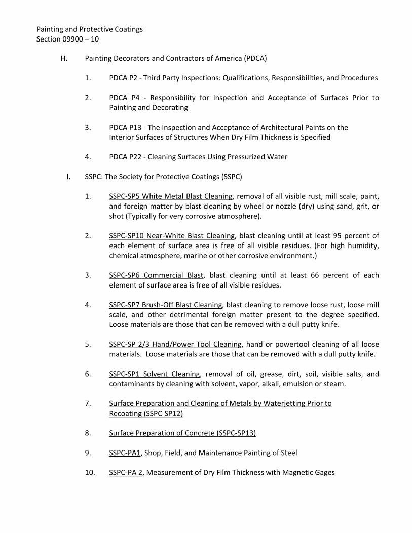
Painting and Protective Coatings Section 09900 – 10
H. Painting Decorators and Contractors of America (PDCA) 1. PDCA P2 - Third Party Inspections: Qualifications, Responsibilities, and Procedures 2. PDCA P4 - Responsibility for Inspection and Acceptance of Surfaces Prior to
Painting and Decorating
3. PDCA P13 - The Inspection and Acceptance of Architectural Paints on the Interior Surfaces of Structures When Dry Film Thickness is Specified 4. PDCA P22 - Cleaning Surfaces Using Pressurized Water
I. SSPC: The Society for Protective Coatings (SSPC) 1. SSPC-SP5 White Metal Blast Cleaning, removal of all visible rust, mill scale, paint,
and foreign matter by blast cleaning by wheel or nozzle (dry) using sand, grit, or shot (Typically for very corrosive atmosphere).
2. SSPC-SP10 Near-White Blast Cleaning, blast cleaning until at least 95 percent of
each element of surface area is free of all visible residues. (For high humidity, chemical atmosphere, marine or other corrosive environment.)
3. SSPC-SP6 Commercial Blast, blast cleaning until at least 66 percent of each
element of surface area is free of all visible residues.
4. SSPC-SP7 Brush-Off Blast Cleaning, blast cleaning to remove loose rust, loose mill scale, and other detrimental foreign matter present to the degree specified. Loose materials are those that can be removed with a dull putty knife.
5. SSPC-SP 2/3 Hand/Power Tool Cleaning, hand or powertool cleaning of all loose
materials. Loose materials are those that can be removed with a dull putty knife. 6. SSPC-SP1 Solvent Cleaning, removal of oil, grease, dirt, soil, visible salts, and
contaminants by cleaning with solvent, vapor, alkali, emulsion or steam.
7. Surface Preparation and Cleaning of Metals by Waterjetting Prior to Recoating (SSPC-SP12)
8. Surface Preparation of Concrete (SSPC-SP13) 9. SSPC-PA1, Shop, Field, and Maintenance Painting of Steel
10. SSPC-PA 2, Measurement of Dry Film Thickness with Magnetic Gages

Painting and Protective Coatings Section 09900 – 11
11. SSPC-VIS 1, Visual Standard for Abrasive Blast Cleaned Steel 12. SSPC-VIS 2, Standard Method of Evaluating Degree of Rusting on Painted Steel
Surfaces
13. SSPC-VIS 3, Visual Standard for Hand and Power Tool Cleaned Steel 14. SSPC Guide 12, Guide for Illumination of Industrial Painting Projects
15. SSPC Publication No. 91-12, Coating and Lining Inspection Manual 16. SSPC-SSPC Visual Comparison Manual
J. Equipment and Coating Manufacturers' Published Instructions.
1.10 COMPLIANCE WITH ENVIRONMENTAL REGULATORY REQUIREMENTS
A. Contractor shall comply with all current federal, state, and local environmental laws and regulations, including, but not limited to the laws and regulations of the U.S. Environmental Protection Agency (USEPA), the California Air Resources Board (CARB), and the South Coast Air Quality Management District (SCAQMD).
1.11 SUBMITTALS
A. For compliance with these Specifications, the Contractor shall prepare and submit paint and protective coating samples of each finish, including all coats thereof, to the Owner for review, as specified. The samples shall be clearly marked with the manufacturer's name and product identification, and shall be submitted in sufficient time to allow for review, and, if necessary, resubmittal without causing any delay of the Project.
B. Coating Materials List
1. The Contractor shall submit paint and coating materials list which indicates the manufacturer and paint number, keyed to the coating schedule herein, for approval of the Owner prior to, or at the time of, submittal of samples required herein.

Painting and Protective Coatings Section 09900 – 12
2. The Contractor shall include with his submittal his protective coating schedule for shop and field coatings of items to receive protection. The schedule shall conform to the specified requirements for surface preparation, priming, and coating for items covered, and shall follow the same requirements for similar work where such work has not been specifically called-out. No bare ferrous nonworking surfaces shall be omitted from the schedule. Particular care shall be taken to cover in sufficient detail the coating of mechanical joints and other mechanical devices, which shall conform to the recommended practice of the manufacturer of the joint or other mechanical devices.
3. Submittals shall be sufficiently early to permit Owner's review and then Contractor's coordination with affected material and equipment suppliers to assure their use of reviewed shop coats of same manufacture as field coats and compatibility with field applied coats for respective coating system.
4. The coating system shall include a letter from the paint or coating manufacturer endorsing the use of the submitted system for the service environment.
5. Coatings to be used on plastic and fiberglass materials shall be certified as acceptable by all plastic and fiberglass manufacturers whose products are to be coated. Certification copies shall be submitted to the Owner. The Contractor shall be certified in writing by the painting and coating material manufacturers as qualified applicators of their products, and copies of the certification submitted to the Owner.
C. Contractor shall submit paint and coatings material manufacturers' printed Product Data
Sheets for materials intended for use in each of various paint and coating systems. Data sheets shall fully describe material as to its intended use, make-up, recommended surface preparation and application conditions, primers, material mixing and application (including recommended dry mil thickness), thinners, precautions, safety and maintenance cleaning directions.
1.12 PROTECTION OF WORK
A. The Contractor shall be responsible for any and all damage to his work or the work of others during the time his work is in progress. The Contractor shall conduct all operations so as to confine general debris, abrasive blasting debris, and paint overspray to within the bounds of the site. The Contractor shall take all precautions necessary to prevent adverse consequences of painting operations. Any complaints received by the Owner relating to any such potential problems will be immediately delivered to the Contractor. The Contractor shall immediately halt work and shall take whatever corrective action is required to mitigate any such problems. All costs associated with protection of off-site properties and/or correction of damage to property as a result of painting operations shall be borne directly by the Contractor at no additional expense to the Owner.
Painting and Protective Coatings Section 09900 – 13
PART 2 - PRODUCTS
2.01 GENERAL
A. Surfaces to receive paint and protective coating materials as herein specified in this Section shall be coated in conformance with the applicable coating systems specified herein. All materials specified by name and/or manufacturer or selected for use under these Specifications shall be delivered unopened at the job site in their original containers and shall not be opened until inspected by the Owner. Whenever a manufacturer's brand name is specified, it is intended to define the general type and quality of paint or coating desired. Other coatings or paints of equal quality may be used, under the approval of the Engineer.
B. Coating materials shall be as specified herein or approved equal. Architectural paint
finishes are specified hereinafter. All paint and coatings shall be produced and applied as herein called for, or, if not specifically called for, it shall be applied in accordance with the manufacturer's printed recommendations as reviewed by Owner. So far as possible, all paint and coating materials shall be provided by a single source supplier.
C. Materials specified are those which have been evaluated for the specific service.
Products are listed to establish a standard of quality. Standard products of manufacturers other than those specified will be accepted when proven to the satisfaction of the Engineer they are equal in composition, durability, usefulness and convenience for the purpose intended. Substitutions will be considered provided the following minimum conditions are met:
1. The proposed coating or paint system shall have a dry film thickness equal to or
greater than that of the specified system.
2. The proposed coating or paint system shall employ an equal or greater number of separate coats.
3. The proposed coating or paint system shall employ coatings or paints of the same
generic type.
4. All requests for substitution shall carry full descriptive literature and directions for application, along with complete information on generic type, non-volatile content by volume and a list of 10 similar projects, all at least three years old, where the coatings or paints have been applied to similar exposure. Substitutions shall be endorsed in writing from the materials manufacturer that these substituted materials will provide equivalent performance as those specified.
5. If the above mentioned data appears to be in order, the Engineer may require
that the Contractor provide certified laboratory data sheets showing the results

Painting and Protective Coatings Section 09900 – 14
of complete spectrographic and durability tests accomplished on the proposed substitute. An independent testing laboratory satisfactory to the Engineer shall accomplish tests and all costs incurred in the testing program shall be borne by the Contractor. In any case, the Engineer shall be sole and final judge of the acceptability of any proposed substitution. Requests for substitution must be approved in writing.
D. Flammability, toxicity, allergenic properties, and any other characteristic requiring field
precautions shall be identified and specific safety practices shall be stipulated.
E. All paint and coating materials shall be stored in enclosed structures to protect them from weather and excessive heat or cold. Flammable coatings and paints must be stored to conform to local, county, state and federal safety codes for flammable coating and paint materials. At all time the paint and coatings shall be protected from freezing.
2.02 PAINT AND COATING MATERIALS
A. Paint and protective coating materials shall be sealed in containers that plainly show the designated name, formula or specification number, batch number, color, date of manufacture, manufacturer's directions, and name of manufacturer, all of which shall be plainly legible at the time of use. Pigmented paints shall be furnished in containers not larger than five (5) gallons.
B. Materials shall conform to the specifications shown herein and to the requirements
hereinafter specified. Containers shall not be opened or used until Engineer has physically inspected contents and obtained necessary data from information printed on containers or labels. Materials exceeding storage life recommended by the manufacturer shall be rejected.
C. Products shall be standard for recognized manufacturer engaged in production of such
materials for essentially identical or similar applications in the water and wastewater treatment industry and industrial plants.
D. Only compatible materials shall be used in the Work. Particular attention shall be directed to compatibility of primers and finish coats. If necessary, subject to review of the Owner, a compatible barrier coat shall be applied between all existing prime coats and subsequent field coats to ensure compatibility.
E. All colors and shades of colors of all coats of paints and protective coating material shall be as selected by the Owner. Each coat shall be of a slightly different color to facilitate inspection of surface coverage of each coat.
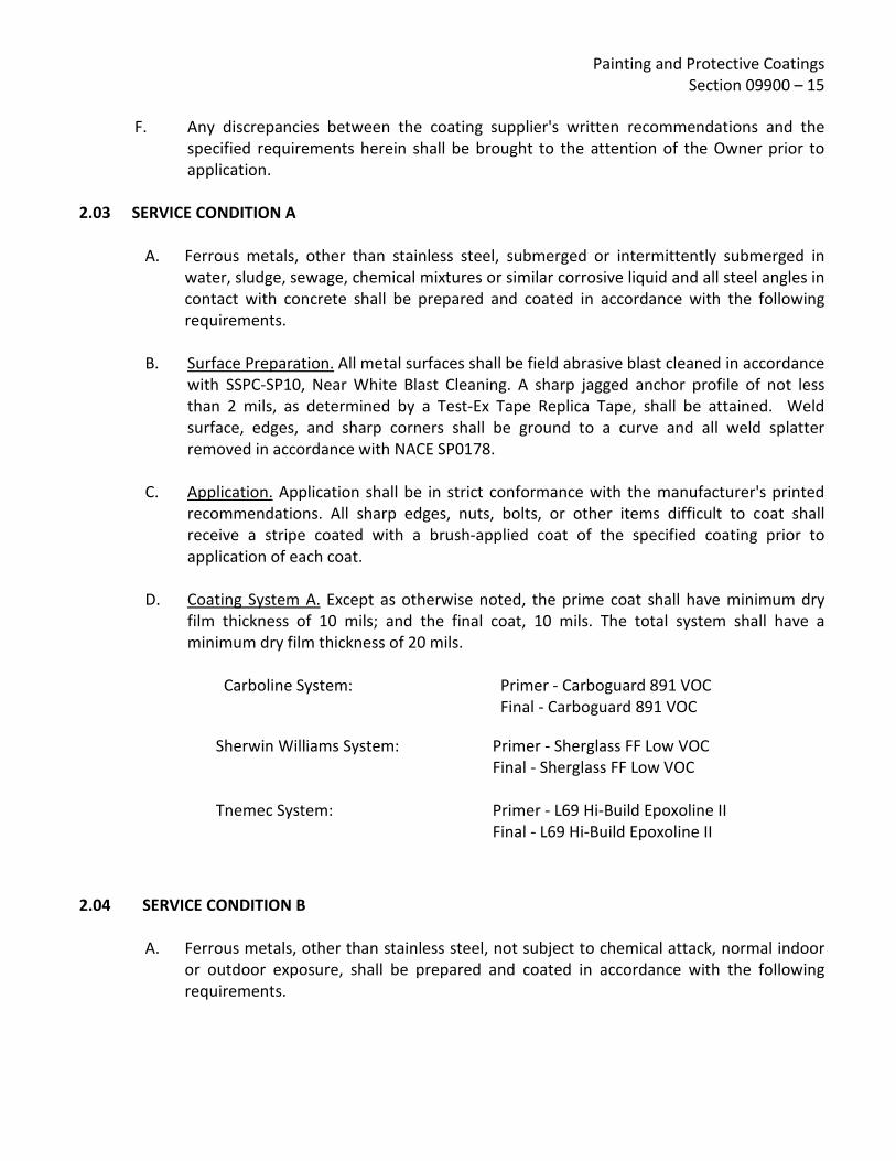
Painting and Protective Coatings Section 09900 – 15
F. Any discrepancies between the coating supplier's written recommendations and the
specified requirements herein shall be brought to the attention of the Owner prior to application.
2.03 SERVICE CONDITION A
A. Ferrous metals, other than stainless steel, submerged or intermittently submerged in
water, sludge, sewage, chemical mixtures or similar corrosive liquid and all steel angles in contact with concrete shall be prepared and coated in accordance with the following requirements.
B. Surface Preparation. All metal surfaces shall be field abrasive blast cleaned in accordance
with SSPC-SP10, Near White Blast Cleaning. A sharp jagged anchor profile of not less than 2 mils, as determined by a Test-Ex Tape Replica Tape, shall be attained. Weld surface, edges, and sharp corners shall be ground to a curve and all weld splatter removed in accordance with NACE SP0178.
C. Application. Application shall be in strict conformance with the manufacturer's printed recommendations. All sharp edges, nuts, bolts, or other items difficult to coat shall receive a stripe coated with a brush-applied coat of the specified coating prior to application of each coat.
D. Coating System A. Except as otherwise noted, the prime coat shall have minimum dry film thickness of 10 mils; and the final coat, 10 mils. The total system shall have a minimum dry film thickness of 20 mils.
Carboline System: Primer - Carboguard 891 VOC Final - Carboguard 891 VOC
Sherwin Williams System: Primer - Sherglass FF Low VOC Final - Sherglass FF Low VOC
Tnemec System: Primer - L69 Hi-Build Epoxoline II Final - L69 Hi-Build Epoxoline II
2.04 SERVICE CONDITION B
A. Ferrous metals, other than stainless steel, not subject to chemical attack, normal indoor or outdoor exposure, shall be prepared and coated in accordance with the following requirements.
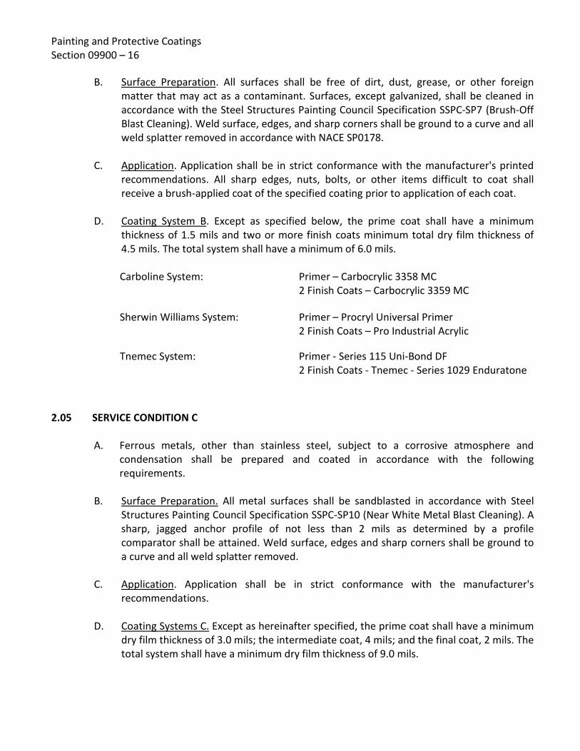
Painting and Protective Coatings Section 09900 – 16
B. Surface Preparation. All surfaces shall be free of dirt, dust, grease, or other foreign matter that may act as a contaminant. Surfaces, except galvanized, shall be cleaned in accordance with the Steel Structures Painting Council Specification SSPC-SP7 (Brush-Off Blast Cleaning). Weld surface, edges, and sharp corners shall be ground to a curve and all weld splatter removed in accordance with NACE SP0178.
C. Application. Application shall be in strict conformance with the manufacturer's printed recommendations. All sharp edges, nuts, bolts, or other items difficult to coat shall receive a brush-applied coat of the specified coating prior to application of each coat.
D. Coating System B. Except as specified below, the prime coat shall have a minimum thickness of 1.5 mils and two or more finish coats minimum total dry film thickness of 4.5 mils. The total system shall have a minimum of 6.0 mils. Carboline System: Primer – Carbocrylic 3358 MC
2 Finish Coats – Carbocrylic 3359 MC
Sherwin Williams System: Primer – Procryl Universal Primer 2 Finish Coats – Pro Industrial Acrylic
Tnemec System: Primer - Series 115 Uni-Bond DF 2 Finish Coats - Tnemec - Series 1029 Enduratone
2.05 SERVICE CONDITION C
A. Ferrous metals, other than stainless steel, subject to a corrosive atmosphere and condensation shall be prepared and coated in accordance with the following requirements.
B. Surface Preparation. All metal surfaces shall be sandblasted in accordance with Steel Structures Painting Council Specification SSPC-SP10 (Near White Metal Blast Cleaning). A sharp, jagged anchor profile of not less than 2 mils as determined by a profile comparator shall be attained. Weld surface, edges and sharp corners shall be ground to a curve and all weld splatter removed.
C. Application. Application shall be in strict conformance with the manufacturer's recommendations.
D. Coating Systems C. Except as hereinafter specified, the prime coat shall have a minimum dry film thickness of 3.0 mils; the intermediate coat, 4 mils; and the final coat, 2 mils. The total system shall have a minimum dry film thickness of 9.0 mils.

Painting and Protective Coatings Section 09900 – 17
Carboline System: Primer - Carbozinc 11HS (Shop)
Primer - Carbozinc 859 VOC (field) Intermediate - Carboguard 890 VOC Finish - Carbothane 133 MC
Sherwin Williams System: Primer – Corothane I Galvapak -100 Intermediate – Macropoxy 646-100 Finish – Hi Solids Polyurethane-100
Tnemec System: Primer - Series 94H2O Tnem Zinc Intermediate - L69 Hi-Build Expoxoline II Finish - 750 UVX Hybrid Polyurethane, Semi- Gloss
2.06 SERVICE CONDITION D
A. Concrete which is subject to submerged and intermittent submergence in water, sludge or chemical mixtures, or which is exposed to corrosive atmospheres, shall be prepared and coated in accordance with the following requirements:
B. Surface Preparation.
1. All green concrete surfaces shall be aged for at least 30 days prior to application.
2. Prior to final preparation of the concrete surfaces, the contractor shall thoroughly clean the surfaces to be lined to remove dirt, residue, and other foreign deposits. Surfaces shall be tested by placing droplets of clean water onto sample locations. Satisfactory surfaces will allow water to be easily absorbed or penetrated into the concrete, while contaminated surfaces will result in the water beading. Contaminated surfaces shall be cleaned. Surfaces showing evidence of such contamination shall be cleaned using solutions of caustic soda or trisodium phosphate (TSP). They should be applied with vigorous scrubbing, followed by flushing with fresh water to remove all traces of both the detergent and contaminant and then allowed to thoroughly dry.
3. The contractor shall use either abrasive blasting or high-pressure waterjetting surface preparation methods to remove any loose concrete and produce a clean, contamination-free, sound, roughened surface acceptable to the lining manufacturer. Abrasive blast cleaning shall be completed in accordance with SSPC-SP7 and SSPC-SP13. The actual water pressure required during any water jetting to achieve the proper removal of deteriorated concrete is not known, but it is projected that pressures between 10,000 to 30,000 psi will be required. Any water jetting equipment shall utilize an oscillating tip.

Painting and Protective Coatings Section 09900 – 18
4. No efflorescence, laitance, or deteriorated concrete shall remain following final surface preparation. Only sound concrete shall remain. The remaining sound concrete shall be uniformly gray in color and appearance.
5. The integrity testing of the prepared concrete shall include dragging the dull edge of putty knife along the prepared surfaces. Properly prepared surfaces will leave behind a scratch without substantial substrate removal. Areas where the scraping action leaves behind a groove or indentation shall be further prepared and retested.
6. All surfaces shall have a surface profile or anchor pattern equal to the International Concrete Repair Institute (ICRI) replica coupon recommended by the coating suppler.
7. The pH of the prepared concrete shall range between 7.0 and 9.0. The pH of the prepared surfaces shall be tested by the contractor according to ASTM D4262.
8. If any reinforcing steel is exposed after removing concrete, it shall be thoroughly cleaned by sandblasting to a near-white metal blast condition (SSPC-SP10).
9. The moisture vapor transmission of the area shall be tested in accordance with ASTM D4263. All testing shall be completed by the contractor and witnessed by the Owner.
10. Prior to installing the coating system, the Contractor shall fill all surface areas with depressions deeper than 1/4-inch by filling in with a resurfacing material that is compatible with the coating system selected. The Contractor shall follow the instructions and recommendations of the manufacturer as to application, curing time requirements, depth of repair, and surface preparation procedures. Any resurfacing material shall be properly prepared through scarification prior to the application of any coatings.
11. The Contractor shall not start application until the surface pH, moisture content, and surface temperature are within the recommended limits, and the prepared surfaces have been accepted by the Engineer. Application shall only be performed when the surface temperature is stable or on the decline.
12. Leading Edges/Terminations: If in the opinion of the Engineer the concrete surfaces specified for coating application does not include a well defined beginning or ending anchor (e.g. terminating edge on lined concrete) or a proper anchored transition between concrete and steel substrates, the coating shall be mechanically anchored to a dry, clean saw cut to a minimum depth of 1/4 inch and width of 1/4 inch. This includes any steel appurtenances penetrating concrete surfaces. The coating system shall be applied into the saw cut to full depth.

Painting and Protective Coatings Section 09900 – 19
13. Should cracks be identified after preparation of concrete that require sealing to
assure prevention of moisture intrusion or proper continuous lining work, seal all cracks in accordance with the written recommendations of the lining suppler, as approved by the Engineer.
C. Application. Application shall be in strict conformance with the manufacturer's printed
recommendations. All coats shall be applied within 24 hours of the previous coat and within the written recoat limitations.
D. Coating System D. The prime coat shall have a minimum dry film thickness of 6 mils and two finish coats shall have a minimum total dry film thickness of 16 mils. The total system shall have a minimum dry film thickness of 22 mils. Sherwin Williams System : Prime – Corobond 100
Two Finish Coats – Sherglass FF Low VOC
Tnemec System: Primer - Series 218 MortarClad (surfacer) Two Finish Coats - 436 Perma-Shield FR
2.07 SERVICE CONDITION E
A. Concrete surface subject to corrosive atmosphere and condensation shall be prepared and coated in accordance with the following requirements.
B. Surface Preparation.
1. All concrete surfaces shall be aged for at least 30 days prior to application.
2. Prior to final preparation of the concrete surfaces, the Contractor shall thoroughly clean the surfaces to be lined to remove dirt, residue, and other foreign deposits. Surfaces shall be tested by placing droplets of clean water onto sample locations. Satisfactory surfaces will allow water to be easily absorbed or penetrated into the concrete, while contaminated surfaces will result in the water beading. Contaminated surfaces shall be cleaned. Surfaces showing evidence of such contamination shall be cleaned using solutions of caustic soda or trisodium phosphate (TSP). They should be applied with vigorous scrubbing, followed by flushing with fresh water to remove all traces of both the detergent and contaminant and then allowed to thoroughly dry.
3. The Contractor shall use either abrasive blasting or high-pressure waterjetting surface preparation methods to remove any loose concrete and produce a clean, contamination-free, sound, roughened surface acceptable to the lining manufacturer. Abrasive blast cleaning shall be completed in accordance with SSPC-SP7 and SSPC-SP13. The actual water pressure required during any water

Painting and Protective Coatings Section 09900 – 20
jetting to achieve the proper removal of deteriorated concrete is not known, but it is projected that pressures between 10,000 to 30,000 psi will be required. Any water jetting equipment shall utilize an oscillating tip.
4. No efflorescence, laitance, or deteriorated concrete shall remain following final surface preparation. Only sound concrete shall remain. The remaining sound concrete shall be uniformly gray in color and appearance.
5. The integrity testing of the prepared concrete shall include dragging the dull edge of putty knife along the prepared surfaces. Properly prepared surfaces will leave behind a scratch without substantial substrate removal. Areas where the scraping action leaves behind a groove or indentation shall be further prepared and retested.
6. All surfaces shall have a surface profile or anchor pattern equal to the International Concrete Repair Institute (ICRI) replica coupon recommended by the coating suppler.
7. The pH of the prepared concrete shall range between 7.0 and 9.0. The pH of the prepared surfaces shall be tested by the Contractor according to ASTM D4262.
8. If any reinforcing steel is exposed after removing concrete, it shall be thoroughly cleaned by sandblasting to a near-white metal blast condition (SSPC-SP10).
9. The moisture vapor transmission of the area shall be tested in accordance with ASTM D4263. All testing shall be completed by the Contractor and witnessed by the Owner.
10. Prior to installing the coating system, the Contractor shall fill all surface areas with depressions deeper than 1/4-inch by filling in with a resurfacing material that is compatible with the coating system selected. The Contractor shall follow the instructions and recommendations of the manufacturer as to application, curing time requirements, depth of repair, and surface preparation procedures. Any resurfacing material shall be properly prepared through scarification prior to the application of any coatings.
11. The Contractor shall not start application until the surface pH, moisture content, and surface temperature are within the recommended limits, and the prepared surfaces have been accepted by the Engineer. Application shall only be performed when the surface temperature is stable or on the decline.
12. Leading Edges/Terminations: If in the opinion of the Engineer the concrete surfaces specified for coating application does not include a well defined beginning or ending anchor (e.g. terminating edge on lined concrete) or a proper anchored transition between concrete and steel substrates, the coating shall be mechanically anchored to a dry, clean saw cut to a minimum depth of 1/4 inch
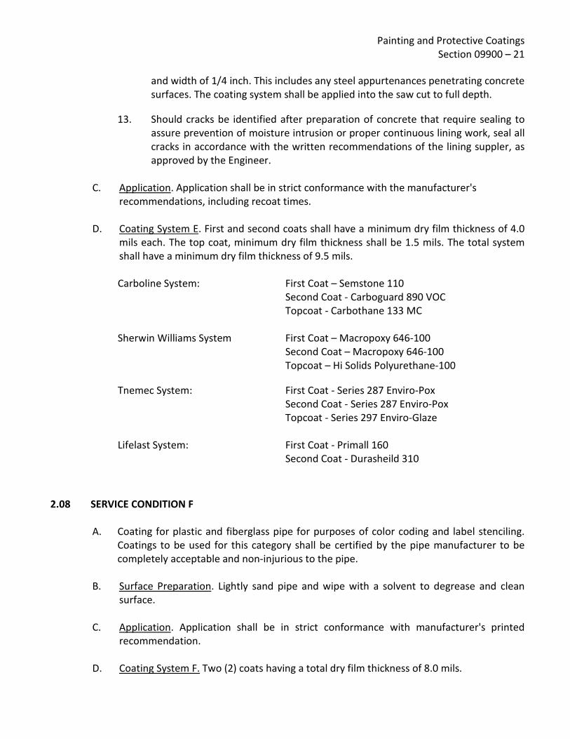
Painting and Protective Coatings Section 09900 – 21
and width of 1/4 inch. This includes any steel appurtenances penetrating concrete surfaces. The coating system shall be applied into the saw cut to full depth.
13. Should cracks be identified after preparation of concrete that require sealing to assure prevention of moisture intrusion or proper continuous lining work, seal all cracks in accordance with the written recommendations of the lining suppler, as approved by the Engineer.
C. Application. Application shall be in strict conformance with the manufacturer's
recommendations, including recoat times.
D. Coating System E. First and second coats shall have a minimum dry film thickness of 4.0 mils each. The top coat, minimum dry film thickness shall be 1.5 mils. The total system shall have a minimum dry film thickness of 9.5 mils. Carboline System: First Coat – Semstone 110
Second Coat - Carboguard 890 VOC Topcoat - Carbothane 133 MC
Sherwin Williams System First Coat – Macropoxy 646-100 Second Coat – Macropoxy 646-100 Topcoat – Hi Solids Polyurethane-100
Tnemec System: First Coat - Series 287 Enviro-Pox Second Coat - Series 287 Enviro-Pox Topcoat - Series 297 Enviro-Glaze
Lifelast System: First Coat - Primall 160 Second Coat - Durasheild 310
2.08 SERVICE CONDITION F
A. Coating for plastic and fiberglass pipe for purposes of color coding and label stenciling. Coatings to be used for this category shall be certified by the pipe manufacturer to be completely acceptable and non-injurious to the pipe.
B. Surface Preparation. Lightly sand pipe and wipe with a solvent to degrease and clean
surface.
C. Application. Application shall be in strict conformance with manufacturer's printed recommendation.
D. Coating System F. Two (2) coats having a total dry film thickness of 8.0 mils.
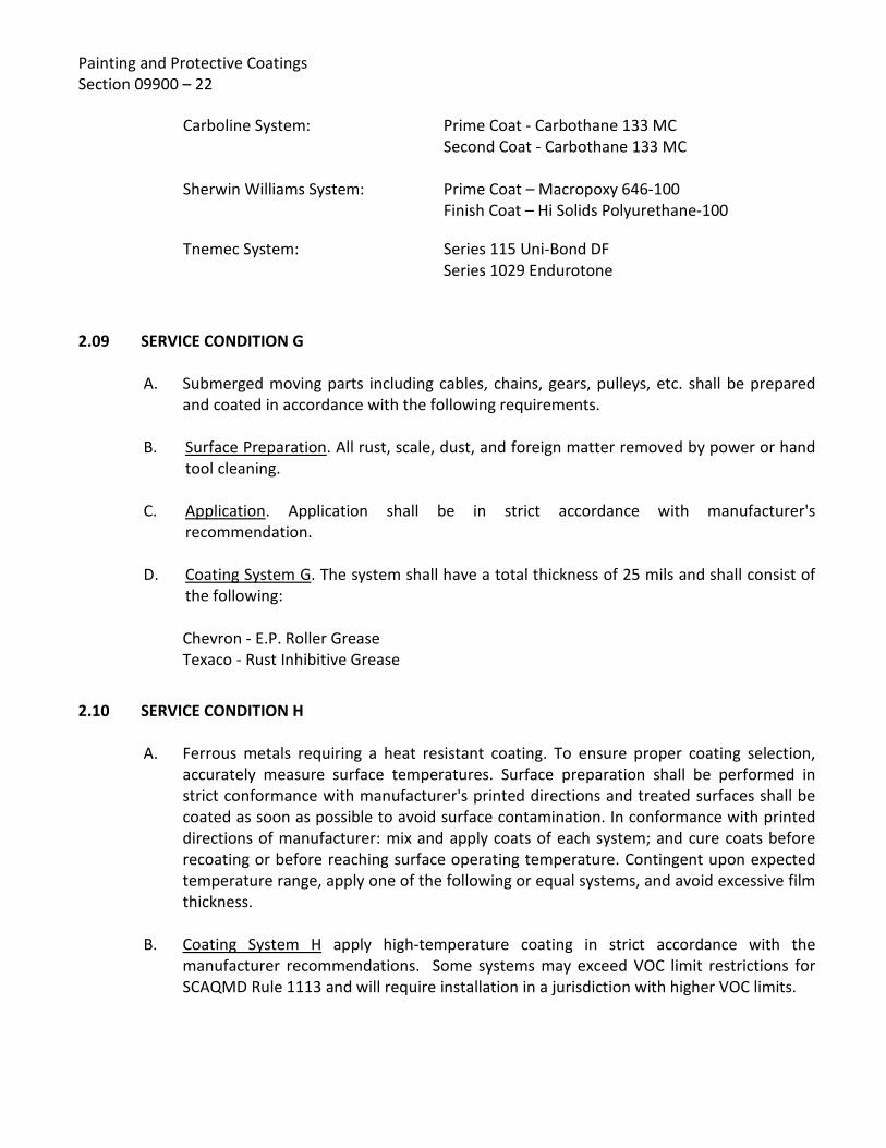
Painting and Protective Coatings Section 09900 – 22
Carboline System: Prime Coat - Carbothane 133 MC Second Coat - Carbothane 133 MC
Sherwin Williams System: Prime Coat – Macropoxy 646-100 Finish Coat – Hi Solids Polyurethane-100
Tnemec System: Series 115 Uni-Bond DF Series 1029 Endurotone
2.09 SERVICE CONDITION G
A. Submerged moving parts including cables, chains, gears, pulleys, etc. shall be prepared and coated in accordance with the following requirements.
B. Surface Preparation. All rust, scale, dust, and foreign matter removed by power or hand
tool cleaning.
C. Application. Application shall be in strict accordance with manufacturer's recommendation.
D. Coating System G. The system shall have a total thickness of 25 mils and shall consist of the following: Chevron - E.P. Roller Grease Texaco - Rust Inhibitive Grease
2.10 SERVICE CONDITION H
A. Ferrous metals requiring a heat resistant coating. To ensure proper coating selection, accurately measure surface temperatures. Surface preparation shall be performed in strict conformance with manufacturer's printed directions and treated surfaces shall be coated as soon as possible to avoid surface contamination. In conformance with printed directions of manufacturer: mix and apply coats of each system; and cure coats before recoating or before reaching surface operating temperature. Contingent upon expected temperature range, apply one of the following or equal systems, and avoid excessive film thickness.
B. Coating System H apply high-temperature coating in strict accordance with the manufacturer recommendations. Some systems may exceed VOC limit restrictions for SCAQMD Rule 1113 and will require installation in a jurisdiction with higher VOC limits.

Painting and Protective Coatings Section 09900 – 23
Rust-Oleum Systems:
300-800o F Temp. Range 4200 System
400-l200o F Temp. Range 4300 System
Carboline Systems:
Up to 450° F Temp. Thermaline 2977 VOC / Thermaline 4900 VOC
400-1200° F Temp. Carbozinc 11 Series / Thermaline 4700 VOC
Sherwin Williams Systems:
Ambient To 250o F: Prime – Corothane I Galvapak -100 Finish – Pro Industrial Acrylic
To 500oF: Prime - Heat-Flex Hi Temp 1200 Finish – Heat-Flex Hi Temp 500
500oF to 1200oF: Prime - Heat-Flex Hi Temp 1200 Finish – Heat-Flex Hi Temp 1100
2.11 SERVICE CONDITION I
A. Coating of concrete and metal surfaces within the extremely corrosive areas as indicated on the Schedule.
B. Surface Preparation - Concrete.
1. All concrete surfaces shall be aged for at least 30 days prior to application.
2. Prior to final preparation of the concrete surfaces, the Contractor shall thoroughly clean the surfaces to be lined to remove dirt, residue, and other foreign deposits. Surfaces shall be tested by placing droplets of clean water onto sample locations. Satisfactory surfaces will allow water to be easily absorbed or penetrated into the concrete, while contaminated surfaces will result in the water beading. Contaminated surfaces shall be cleaned. Surfaces showing evidence of such contamination shall be cleaned using solutions of caustic soda or trisodium phosphate (TSP). They should be applied with vigorous scrubbing, followed by flushing with fresh water to remove all traces of both the detergent and contaminant and then allowed to thoroughly dry.

Painting and Protective Coatings Section 09900 – 24
3. The Contractor shall use either abrasive blasting or high-pressure waterjetting surface preparation methods to remove any loose concrete and produce a clean, contamination-free, sound, roughened surface acceptable to the lining manufacturer. Abrasive blast cleaning shall be completed in accordance with SSPC-SP7 and SSPC-SP13. The actual water pressure required during any water jetting to achieve the proper removal of deteriorated concrete is not known, but it is projected that pressures between 10,000 to 30,000 psi will be required. Any water jetting equipment shall utilize an oscillating tip.
4. No efflorescence, laitance, or deteriorated concrete shall remain following final surface preparation. Only sound concrete shall remain. The remaining sound concrete shall be uniformly gray in color and appearance.
5. The integrity testing of the prepared concrete shall include dragging the dull edge of putty knife along the prepared surfaces. Properly prepared surfaces will leave behind a scratch without substantial substrate removal. Areas where the scraping action leaves behind a groove or indentation shall be further prepared and retested.
6. All surfaces shall have a surface profile or anchor pattern equal to the International Concrete Repair Institute (ICRI) replica coupon recommended by the coating suppler.
7. The pH of the prepared concrete shall range between 7.0 and 9.0. The pH of the prepared surfaces shall be tested by the Contractor according to ASTM D4262.
8. If any reinforcing steel is exposed after removing concrete, it shall be thoroughly cleaned by sandblasting to a near-white metal blast condition (SSPC-SP10).
9. The moisture vapor transmission of the area shall be tested in accordance with ASTM D4263. All testing shall be completed by the Contractor and witnessed by the Owner.
10. Prior to installing the coating system, the Contractor shall fill all surface areas with depressions deeper than 1/4-inch by filling in with a resurfacing material that is compatible with the coating system selected. The Contractor shall follow the instructions and recommendations of the manufacturer as to application, curing time requirements, depth of repair, and surface preparation procedures. Any resurfacing material shall be properly prepared through scarification prior to the application of any coatings.
11. The Contractor shall not start application until the surface pH, moisture content, and surface temperature are within the recommended limits, and the prepared surfaces have been accepted by the Engineer. Application shall only be performed when the surface temperature is stable or on the decline.

Painting and Protective Coatings Section 09900 – 25
12. Leading Edges/Terminations: If in the opinion of the Engineer the concrete
surfaces specified for coating application does not include a well defined beginning or ending anchor (e.g. terminating edge on lined concrete) or a proper anchored transition between concrete and steel substrates, the coating shall be mechanically anchored to a dry, clean saw cut to a minimum depth of 1/4 inch and width of 1/4 inch. This includes any steel appurtenances penetrating concrete surfaces. The coating system shall be applied into the saw cut to full depth.
13. Should cracks be identified after preparation of concrete that require sealing to assure prevention of moisture intrusion or proper continuous lining work, seal all cracks in accordance with the written recommendations of the lining suppler, as approved by the Engineer.
C. Surface Preparation - Steel.
1. All metal surfaces shall be field abrasive blast cleaned in accordance with SSPC-
SP10, Near White Blast Cleaning. A sharp, jagged anchor profile not less than 3.5 mils shall be attained. Weld surface, edges, and sharp corners shall be ground to a curve and all weld splatter removed in accordance with NACE SP0178.
D. Application. Application shall be in strict conformance with the manufacturer's printed
recommendations. The applicator shall be a licensed applicator by the coating manufacturer. The finished coating shall be spark tested and all holidays repaired in accordance with NACE SP0188.
E. Coating System I. Except as otherwise noted, the prime coat on metal surfaces shall have a minimum thickness of 2.0 mils and a maximum thickness of 3.0 mils. The finish coat on a non-abrasive metal surface shall be 30 mils and in an abrasive area shall be 40 mils. The prime coat on concrete surfaces shall have a minimum thickness of 3.0 mils and a maximum thickness of 5.0 mils. The finish coat shall be a minimum 65 mils dry film thickness.
Carboline System: Primer - Plasite 4503
Topcoat - Reacatamine 760 Series
Sherwin Williams System: Concrete Primer - Corobond 300 Steel Primer – Macropoxy 646-100 Finish Coat – Sherflex Elastomeric Polyurethane
Sancon System: Concrete Primer - Sancon 100 Epoxy Steel Primer - United 302 Urethane Topcoat - Sancon 100 Polyurethane
Lifelast System: Concrete Primer - Primall 160 Topcoat - Durachield 310

Painting and Protective Coatings Section 09900 – 26 2.12 ARCHITECTURAL PAINT FINISHES
A. Manufacturer. Unless otherwise noted, products listed below are the standards of quality. Other materials may be approved if they meet the requirements of Section 2.01. 1. System P–1 - Enamel on Structural Steel Members
Frazee Paint System:
First Coat - C309 UltraTech Water-Based Universal Metal Primer (Delete on factory primed materials) Second Coat - 136 Aro-Thane Water-Based Urethane Modified Alkyd Semi-Gloss Third Coat - 136 Aro-Thane Water-Based Urethane Modified Alkyd Semi-Gloss
Sherwin Williams System:
First Coat – Procryl Universal Primer (Delete on factory or shop primed materials) Second Coat – Procryl Universal Primer Third Coat – Pro Industrial Acrylic Fourth Coat – Pro Industrial Acrylic
Vista Paint System: First Coat - Vista 9600 Protec Primer (Delete on factory primed materials) Second Coat - Vista 9800 Protec Semi-Gloss Enamel Third Coat - Vista 9800 Protec Semi-Gloss Enamel
Dunn Edwards System: First Coat - BLOC-RUST Premium Red Rust
Preventative Primer (BRPR00-1-RO) (delete on factory primed materials)
Second Coat – Ultrashield – Gloss ULSH60 Third Coat – Ultrashield Gloss ULSH60 Fourth Coat – not necessary

Painting and Protective Coatings Section 09900 – 27
2. System P-2 - Concrete Masonry Paint on Concrete Unit Masonry
Frazee Paint System:
First Coat - C251 Flex Lox Epoxy-Acrylic High pH Masonry Primer
Second Coat - 146 Aro-Thane Water Based Urethane Mod. Alkyd Gloss Second Coat - 146 Aro-Thane Water Based Urethane Mod. Alkyd Gloss
Sherwin Williams System:
Monochem System: First Coat – Aquaseal ME12 Second Coat – Permasheeld Premium Third Coat – Permashield Premium
Vista Paint System: First Coat - Vista 4600 Uniprime II Masonry Primer Second Coat- Vista 290 Uretech Acrylic Gloss Urethane Third Coat - Vista 290 Uretech Acrylic Gloss Urethane
Dunn Edwards System: First coat – Carboline – Sanitile 100 (If on concrete
block) First coat – Carboline – Sanitile 120 (If not on block) Second coat– Carboline, Carbothane 134 Third coat – Carboline, Carbothane 134
3. System P-3 - Concrete Masonry Paint on Concrete
Frazee Paint System:
First Coat - 203 Duratec II Exterior 100% Acrylic Flat Second Coat - 203 Duratec II Exterior 100% Acrylic Flat

Painting and Protective Coatings Section 09900 – 28
Sherwin Williams
System: First Coat – Loxon Concrete Masonry Primer Second Coat – Loxon Acrylic Coating
Vista Paint System: First Coat - Vista 4600 Uniprime II Masonry Primer Second Coat- Vista 2000 Duratone 100% Acrylic Flat Third Coat - Vista 2000 Duratone 100% Acrylic Flat
Dunn Edwards System: First coat - Eff Stop Premium Primer (ESPR00)
Second Coat - Evershield 100% Acrylic (EVSH10) Third Coat - Evershield 100% Acrylic (EVSH10)
4. System P-4 - Enamel on Galvanized Metal (Doors, Frames, & Sheet Metal)
Frazee Paint System:
Pretreatment - Krud Kutter Metal Clean and Etch First Coat - C309 UltraTech Water-Based Universal Primer Second Coat - 136 Aro-Thane Water-Based Urethane Modified Alkyd Semi-Gloss Third Coat - 136 Aro-Thane Water-Based Urethane Modified Alkyd Semi-Gloss
Sherwin Williams System: Pretreatment – Great Lakes Clean and Etch First Coat– Procryl Universal Primer Second Coat - Pro Industrial Acrylic Third Coat – Pro Industrial Acrylic
Vista Paint System: Pretreatment - Jasco Prep N Prime First Coat - Vista 4800 Acrylic Metal Prime

Painting and Protective Coatings Section 09900 – 29
Second Coat - Vista 8400 Carefree 100% Acrylic Semi Gloss Enamel Third Coat - Vista 8400 Carefree 100% Acrylic Semi Gloss Enamel
Dunn Edwards System: Pretreatment – Carboline – Galoseal (if substrate is
unpainted galvanized) First Coat – If previously painted use Ultrashield DTM Gray Primer ULDM00GR Second Coat - Ultrashield Gloss ULSH60 Third Coat - Ultrashield Gloss ULSH60
5. System P-5 - Enamel on Primed Metal
Frazee Paint System:
First Coat - 168 Prime+Plus Primer/Sealer Second Coat - 136 Aro-Thane Water-Based Urethane Modified Alkyd Semi-Gloss
Sherwin Williams System: Prime Repair Coat - Procryl Universal Primer First Coat– Pro Industrial Acrylic Second Coat - Pro Industrial Acrylic
Vista Paint System: First Coat - Vista 8400 Carefree 100% Acrylic Semi Gloss Enamel Second Coat - Vista 8400 Carefree 100% Acrylic Semi Gloss Enamel
Dunn Edwards System: First Coat – Ultrashield Multi Surface Primer ULMS Second Coat - Ultrashield Gloss ULSH60

Painting and Protective Coatings Section 09900 – 30
6. System P-6 - Semi Gloss Enamel Paint on Interior Concrete Unit Masonry Frazee Paint System:
First Coat - C302 Ultra Tech 100% Acrylic Block Filler
Second Coat - 124 Mirro Glide 100% Acrylic Semi-Gloss Second Coat - 124 Mirro Glide 100% Acrylic Semi-Gloss
Sherwin Williams System:
First Coat – Loxon Block Resurfacer Second Coat– Pro Industrial Acrylic First Coat - Pro Industrial Acrylic
Vista Paint System: First Coat - Vista 040 Block Coat Second Coat- Vista 8400 Carefree 100% Acrylic Semi Gloss Enamel Third Coat - Vista 8400 Carefree 100% Acrylic Semi Gloss Enamel
Dunn Edwards System: First Coat - "Blocfill" Smooth W305SMOOTH
BLOCFILL (SBPR00) Second Coat - Decoglo W450SUPREMA (SPMA50) Third Coat - Decoglo W450SUPREMA (SPMA50)
7. System P-7 - Sealer for Unpainted Masonry Surfaces A transparent waterproofing sealer shall be applied to all above grade masonry surfaces, with the exception of interior building walls, both smooth face and split face block as shown on plans and in Coating Systems Schedule. Apply to dry, clean split faced surface with airless spray. Rate of application shall be in accordance with manufacturer’s recommendations.
Frazee Paint System: Monochem 4990 Aquaseal SS Water Repellent
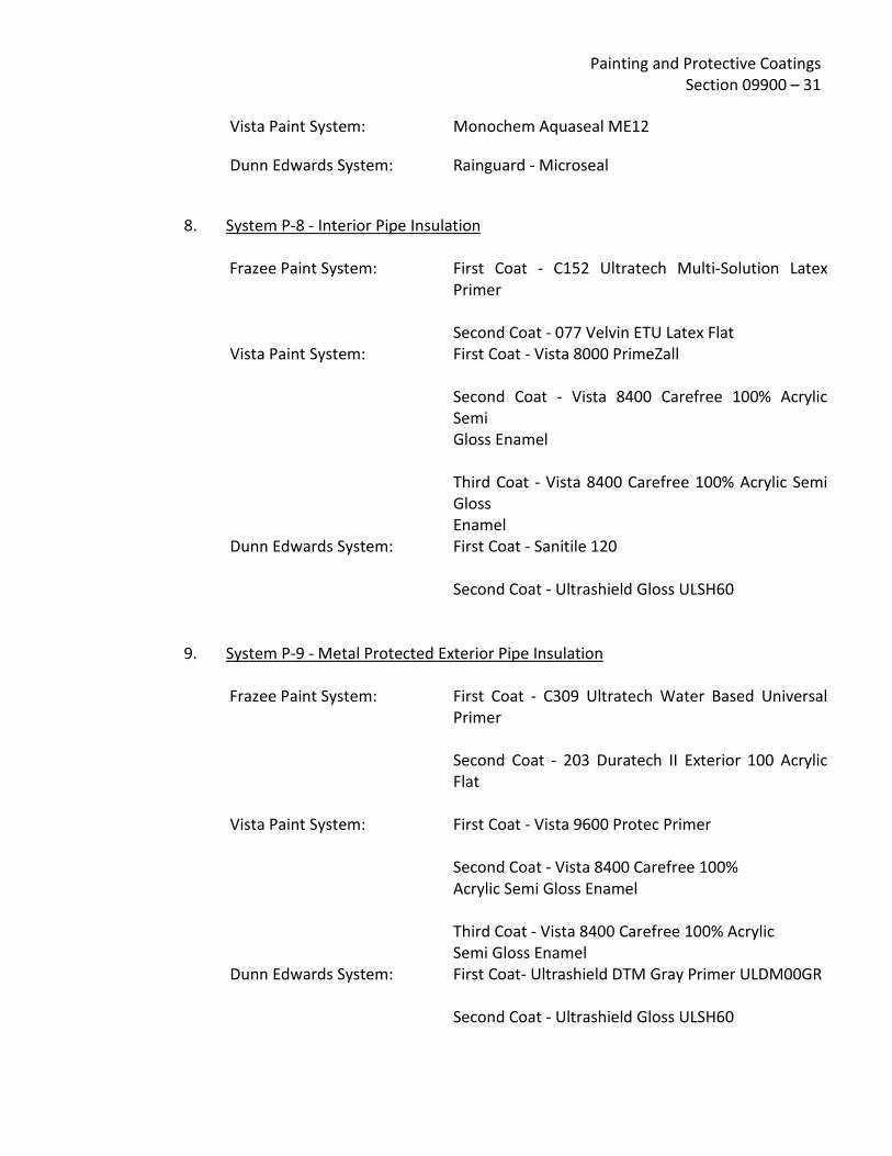
Painting and Protective Coatings Section 09900 – 31
Vista Paint System: Monochem Aquaseal ME12
Dunn Edwards System: Rainguard - Microseal
8. System P-8 - Interior Pipe Insulation
Frazee Paint System:
First Coat - C152 Ultratech Multi-Solution Latex Primer Second Coat - 077 Velvin ETU Latex Flat
Vista Paint System: First Coat - Vista 8000 PrimeZall Second Coat - Vista 8400 Carefree 100% Acrylic Semi Gloss Enamel Third Coat - Vista 8400 Carefree 100% Acrylic Semi Gloss Enamel
Dunn Edwards System: First Coat - Sanitile 120 Second Coat - Ultrashield Gloss ULSH60
9. System P-9 - Metal Protected Exterior Pipe Insulation
Frazee Paint System:
First Coat - C309 Ultratech Water Based Universal Primer Second Coat - 203 Duratech II Exterior 100 Acrylic Flat
Vista Paint System: First Coat - Vista 9600 Protec Primer Second Coat - Vista 8400 Carefree 100% Acrylic Semi Gloss Enamel Third Coat - Vista 8400 Carefree 100% Acrylic Semi Gloss Enamel
Dunn Edwards System: First Coat- Ultrashield DTM Gray Primer ULDM00GR Second Coat - Ultrashield Gloss ULSH60
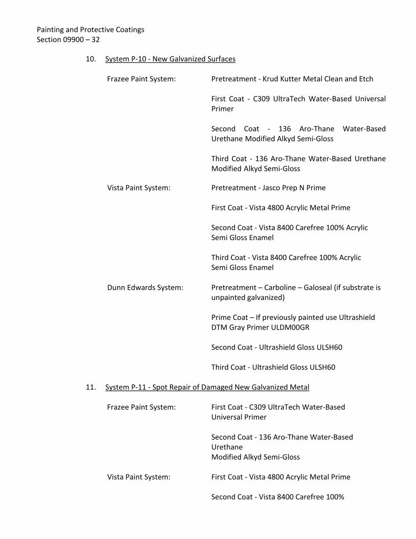
Painting and Protective Coatings Section 09900 – 32
10. System P-10 - New Galvanized Surfaces Frazee Paint System:
Pretreatment - Krud Kutter Metal Clean and Etch First Coat - C309 UltraTech Water-Based Universal Primer Second Coat - 136 Aro-Thane Water-Based Urethane Modified Alkyd Semi-Gloss Third Coat - 136 Aro-Thane Water-Based Urethane Modified Alkyd Semi-Gloss
Vista Paint System: Pretreatment - Jasco Prep N Prime First Coat - Vista 4800 Acrylic Metal Prime Second Coat - Vista 8400 Carefree 100% Acrylic Semi Gloss Enamel Third Coat - Vista 8400 Carefree 100% Acrylic Semi Gloss Enamel
Dunn Edwards System: Pretreatment – Carboline – Galoseal (if substrate is unpainted galvanized) Prime Coat – If previously painted use Ultrashield DTM Gray Primer ULDM00GR Second Coat - Ultrashield Gloss ULSH60 Third Coat - Ultrashield Gloss ULSH60
11. System P-11 - Spot Repair of Damaged New Galvanized Metal
Frazee Paint System:
First Coat - C309 UltraTech Water-Based Universal Primer Second Coat - 136 Aro-Thane Water-Based Urethane Modified Alkyd Semi-Gloss
Vista Paint System: First Coat - Vista 4800 Acrylic Metal Prime Second Coat - Vista 8400 Carefree 100%

Painting and Protective Coatings Section 09900 – 33
Acrylic Semi Gloss Enamel Third Coat - Vista 8400 Carefree 100% Acrylic Semi Gloss Enamel
12. System P-12 - Primer Over Bituminous Coating
Frazee Paint System:
First Coat - Macropoxy 646-100 Fast-Cure (VOC 100 g/l) Second Coat - Macropoxy 646-100 Fast-Cure (VOC 100 g/l)
Vista Paint System: First Coat - Vista 8000 PrimeZall Primer Second Coat - Vista 8400 Carefree 100% Acrylic Semi Gloss Enamel
Third Coat - Vista 8400 Carefree 100% Acrylic Semi Gloss Enamel
Dunn Edwards System: First Coat - Carboline Sanitile 120 Second coat - Ultrashield Gloss ULSH60
2.13 MISCELLANEOUS COATINGS
A. Hydrants, indicator post, traffic posts, guard rails and ladders shall be safety yellow, matching OSHA Safety Yellow Color and using specified Service Condition "B".
B. Handwheels and operating handles of all valves and equipment shall be safety red,
matching OSHA Safety Red Color, using, contingent upon exposure, Coating System "B" in non-corrosive atmosphere and Coating Services Condition "C" in corrosive atmosphere and high humidity exposures.
PART 3 - EXECUTION
3.01 GENERAL
A. All surface preparation, coating and paint application shall conform to applicable standards of SSPC and the manufacturer's printed instructions. Material applied prior to approval of the surface by the Engineer shall be removed and reapplied to the satisfaction of the Engineer at the expense of the Contractor.

Painting and Protective Coatings Section 09900 – 34
B. All work shall be performed by skilled craftsmen qualified to accomplish the required
work in a manner comparable with the best standards of practice. Continuity of personnel shall be maintained and transfer of key personnel shall be coordinated with the Engineer.
C. The Contractor shall provide a supervisor to be at the work site during cleaning,
application operations. The supervisor shall have the authority to sign any change orders, coordinate work and make other decisions pertaining to the fulfillment of their contract.
D. Contractor shall provide approved sanitary facilities for all project personnel, as no
existing facilities will be available to the Contractor. Facilities shall be maintained during the project to complete standards established by Owner, and shall be removed prior to Contractor's departure from the site at completion of the project.
E. Dust, dirt, oil, grease or any foreign matter which will affect the adhesion or durability of
the finish must be removed by washing with clean rags dipped in an approved commercial cleaning solvent, rinsed with clean water and wiped dry with clean rags.
F. The Contractor's painting and coating equipment shall be designed for application of
materials specified and shall be maintained in first class working condition. Compressors shall have suitable traps and filters to remove water and oils from the air. Blotter test shall be accomplished at each start-up period and as deemed necessary by the Engineer. Contractor's equipment shall be subject to approval of the Engineer.
1. Cleanliness of compressed air supply used for conventional equipment or blow
down operations shall be verified daily, and as deemed necessary by Engineer, by directing a stream of air, without abrasive, from the blast nozzle onto a white blotter or cloth for twenty seconds in accordance with ASTM D4285. If air contamination is evident, change filters, clean traps, add moisture separators or filters, or make adjustments as necessary to achieve clean, dry air.
G. Application of the first coat shall follow immediately after surface preparation and
cleaning within an eight-hour working day. Any cleaned areas not receiving first coat within an eight-hour period shall be recleaned prior to application of first coat.
H. Because of the presence of moisture and possible contaminants in the working
atmosphere, care shall be taken to ensure previously coated or painted surfaces are protected or recleaned prior to application of subsequent coat(s). The Engineer shall approve methods of protection and recleaning.
1. The project is subject to intermittent shutdown if, in the opinion of the Engineer,
cleaning, coating and painting operations are creating a localized condition

Painting and Protective Coatings Section 09900 – 35
detrimental to ongoing facility activities, personnel, or adjacent property.
2. In the event of emergency shutdown by the Engineer, Contractor shall
immediately correct deficiencies. All additional costs created by shutdown shall be borne by Contractor.
I. The Contractor shall provide, at his own expense, all necessary power for his operations
under the contract.
J. Inspection: all operations will be monitored 100% by an Owner-appointed quality assurance inspector. All additional costs incurred by off-site inspection shall be borne by the Contractor. These include, but are not limited to travel, lodging, food, auto rental (where applicable) and any other expenses directly related to the inspection.
3.02 QUALITY CONTROL A. Ambient Conditions: no coating shall be applied when the surrounding air temperature
or the temperature of the surface to be coated or painted is below 50 degrees F. No coatings shall be applied at temperatures above 110 degrees F. No coatings shall be applied to wet or damp surfaces or in rain, snow, fog or mist, when the surface temperature is less than 5 degrees F. above the dewpoint, or when it is expected the air temperature will drop below 50 degrees.
B. Dewpoint shall be measured by the use of an instrument such as a Sling Psychrometer in
conjunction with U.S. Department of Commerce Weather Bureau Psychrometric Tables or equivalent in accordance with ASTM D337. Relative humidity shall not be more than 85 percent. If unacceptable conditions are prevalent coating or paint application shall be delayed or postponed until conditions are favorable. The day's coating or paint application shall be completed in time to permit the film sufficient drying time prior to damage though atmospheric conditions. Temperature and dewpoint requirements noted above and herein shall apply to all surface preparation operations, except low and high temperature limits.
C. Surface Preparation: surface preparation will be based upon comparison with: "Pictorial Surface Preparation Standards for Painting Steel Surfaces," SSPC-Vis 1 and as described herein. Anchor profile for prepared steel surfaces shall be sharp and jagged (not peened) and measured by using a nondestructive instrument such as a Testex Press-0-Film System in accordance with ASTM D4417. Anchor profile for prepared concrete shall be measured by using a ICRI CSP comparison coupons.
D. The Contractor shall conduct all operations so as to confine debris and overspray to
within the bounds of the site. The Contractor shall take all precautions necessary to prevent adverse off-site consequences of painting operations. Any complaints received

Painting and Protective Coatings Section 09900 – 36
by the Owner relating to any such potential offsite problems will be immediately delivered to the Contractor. The Contractor shall immediately halt work and shall take whatever corrective action is required to mitigate any such problems. All costs associated with protection of off-site properties and/or correction of damage to property as a result of painting operations shall be borne directly by the Contractor at no additional expense to the Owner.
E. Film Thickness Testing: thickness of each coat of coating shall be checked with a non-
destructive film thickness gauge in accordance with ASTM D7091, where applicable.
F. Inspection Devices: Contractor shall furnish, until final acceptance of coating and painting, inspection devices in good working condition for hardness, adhesion, detection of holidays, and measurement of dry-film thickness of coatings and paints, where required. They shall also furnish National Institute of Standards and Technology/National Bureau of Standards (NIST/NBS) certified thickness calibration plates to test accuracy of thickness gauges. Acceptable devices for ferrous metal surfaces include, but are not limited to Tinker-Rasor Models M-1, AP, and AP-W holiday detectors and SSPC, Type II units for dry film thickness gauging. Inspection devices shall be calibrated and operated in accordance with specified requirements. High-voltage testing shall require written acceptance from the lining manufacturer. Adhesion shall be measured using a fixed alignment, type II pull-off adhesion tester such as an Elcometer 106. Hardness testers shall be Type Shore D or as recommended by the lining manufacturer..
G. Gauges and detectors shall be available at all times until final acceptance of application.
Inspection devices shall be operated by, or in the presence of the Engineer with location and frequency basis determined by the Engineer. The Engineer is not precluded from furnishing his own inspection devices and rendering decisions based solely upon these quality assurance tests. Should in the opinion of the Engineer a 24-hour, continuous reading surface temperature gauge be required to assure that maximum recoat windows are observed, the Contractor shall provide a working calibrated instrument to meet this need. The gauge shall be digital and capable of providing instantaneous average measurements of the temperatures recorded.
3.03 SURFACE PREPARATION, GENERAL - INDUSTRIAL A. Slag, weld spatter, or sharp edges such as those created by flame cutting shall be
removed by chipping and grinding. All sharp edges shall be peened, ground or otherwise blunted as required by the Engineer in accordance with NACE SP 0178. The rolled edges of angles, channels, and wide flange beams do not normally require further rounding unless specifically directed by the Engineer.
B. Abrasive blasting nozzles shall be equipped with "deadman" emergency shut-off nozzles.
Blast nozzle pressure shall be a minimum of 95 P.S.I. and shall be verified by using an approved nozzle pressure gage at each start-up period or as directed by the Engineer.

Painting and Protective Coatings Section 09900 – 37
Number of nozzles used during all blast cleaning operations must be sufficient to insure timely completion of project as approved and directed by Engineer.
C. All blast hose connections shall be connected with external couplings. These connections
shall be taped with duct tape prior to pressurizing. All taped connections shall be visually inspected for leaks within five minutes after start of blast cleaning operations and at the end of blast cleaning operations. Leaking connections shall be immediately repaired to prevent further damage.
D. Particle size of abrasives used in blast cleaning shall be that which will produce a surface
profile or anchor pattern specified herein, or in accordance with recommendations of the manufacturer of the specified coating or paint system to be applied, subject to approval of Engineer. Surface Profile or Anchor pattern shall be sharp and jagged in nature (not peened).
E. Abrasive used in blast cleaning operations shall be new, washed, graded and free of
contaminants, which would interfere with adhesion of coatings and paints and shall not be reused unless specifically approved by the Engineer. Abrasives shall be certified for unconfined dry blasting pursuant to the California Administrative Code, Section 92520 of Subchapter 6, title 17, and shall appear on the current listing of approved abrasives.
F. The Contractor shall select an abrasive media that is proper for the quality of surface
preparation specified. Should it be determined that the production rate and quality of the surface preparation is less than specified, it shall be the Contractor’s responsibility to use other types and/or sizes of abrasive to meet the requirements of this contract. At no time shall considerations of extra effort be considered by the Owner unless, in the opinion of the Engineer the Contractor has explored all alternative means of abrasive blasting during their operations.
G. Blast cleaning from rolling scaffolds shall only be performed within the confines of the
interior perimeter of the scaffold. Reaching beyond the limits of the perimeter will be allowed only if blast nozzle is maintained in a position, which will produce a profile acceptable to the Engineer.
H. The Contractor shall keep the area of work in a clean condition and shall not permit
blasting materials to accumulate as to constitute a nuisance or hazard to the prosecution of the work or the operation of the existing facilities. Spent abrasives and other debris shall be removed at the Contractor's expense as directed by the Engineer. If waste is determined to be hazardous, disposal by Contractor shall meet requirements of all regulatory agencies for handling such wastes.
I. Blast cleaned surfaces shall be cleaned prior to the application of specified coatings or
paints through a combination of blowing with clean dry air, brushing/brooming and/or vacuuming as directed by the Engineer. Air hose for blowing shall be at least 1/2" in

Painting and Protective Coatings Section 09900 – 38
diameter and shall be equipped with a shut-off device.
J. The surfaces of any non-carbon steel substrates, or specialty items (i.e. galvanized, anodized, etc.) shall be properly treated and prepared prior to any coating operations in accordance with the coating manufacturer's written recommendations, subject to approval of the Engineer.
3.04 SURFACE PREPARATION, GENERAL - ARCHITECTURAL
A. Before Priming, correct all finish surfaces which are not properly prepared. Assure that all surfaces to be painted are in a proper condition as required by the manufacturer's written recommendations and will provide a proper uniform appearance. Do not prime any surface that has not been approved by the Engineer.
B. Prior to surface preparation and painting operations, remove all hardware, hardware
accessories, plates, lighting fixtures and similar items in contact with painted surfaces and not to be painted. Replace all removed items following completion of all paint work in the area. Items may be protected and not removed if approved by the Engineer.
C. Program and schedule cleaning and painting so that dust and other contaminants from
the cleaning process will not fall on wet, newly painted surfaces. D. Clean concrete and masonry surfaces of all dirt, encrustations, efflorescence and other
foreign matter. Roughen all glazed surfaces on concrete. E. Clean ferrous metal not provided with a shop prime of all loose rust, mill scale, oil, grease
and foreign matter by wire brushing, scraping or sandblasting as required by the written requirements of the paint manufacturer and SSPC-SP2/3. Clean ferrous metal provided with shop prime of all oil, grease and foreign matter in accordance with SSPC-SP1 and the manufacturer's written requirements.
F. Clean gypsum board (drywall) of all dust, dirt, encrustations and foreign matter.
3.05 APPLICATION, GENERAL A. Coating and paint application shall conform to the requirements of the SSPC's Paint
Application Specification No. 1 (SSPC-PA1), latest revision, for "Shop, Field and Maintenance Painting," the manufacturer of the coating and paint materials printed literature, and as specified herein.
B. All surfaces to receive paint and protective coatings shall be cleaned as specified herein prior to application of coating materials. The Contractor shall examine all surfaces to be coated, and shall correct all surface defects before application of any coating material. Beginning the coating work without reporting unsuitable conditions to the Owner constitutes acceptance of conditions by the Contractor. Any required removal, repair, or

Painting and Protective Coatings Section 09900 – 39
replacement of the work caused by unsuitable conditions shall by done at no additional cost to the Owner. All marred or abraded spots on shop-primed and factory-finished surfaces shall receive touch-up restoration prior to any other coating application.
C. Paint and coating materials shall be protected from exposure to excessive hot or cold
weather, and shall be thoroughly stirred, strained, and kept at a uniform consistency during application. Materials of different manufacturers shall not be mixed together. Packaged materials may be thinned immediately prior to application in accordance with the manufacturer's directions.
D. All coatings shall be thoroughly mixed utilizing an approved slow-speed power mixer
until all components are thoroughly combined and are of a smooth consistency. E. Thinning shall only be permitted as recommended by the manufacturer and approved by
the Engineer, and shall not exceed the limits set by applicable regulatory agencies.
1. If the Contractor applies any coatings which have been modified or thinned to such a degree as to cause them to exceed established VOC levels, Contractor shall be responsible for any fines, costs, remedies, or legal action and costs which may result.
F. Each application of coating and paint shall be applied evenly with a uniform appearance.
The system shall be free of brush marks, unfeathered edges, sags, runs, and evidence of poor workmanship, or any aesthetic defects, as defined by SSPC. Care should be exercised to avoid lapping on glass or hardware. Coating and paint shall be sharply cut to lines. Finished surfaces shall be uniform in appearance and shall be free from defects or blemishes.
G. Coatings shall not be applied when area wind speeds exceed fifteen miles per hour.
H. Protective coverings or drop cloths shall be used to protect floors, concrete, fixtures, equipment, prepared surface and applied coatings. Personnel entering work area shall take precautions to prevent damage or contamination of coated or painted surfaces. Care shall be exercised to prevent coating or paint from being spattered onto surfaces, which are not to be coated or painted. Surfaces from which such material cannot be removed satisfactorily shall be replaced, repainted or recoated as required to produce a finish satisfactory to the Engineer.
I. All welds and irregular surfaces, as defined by the Engineer shall receive a brush coat of
the specified product prior to application of each complete coat. Coating/paint shall be brushed in multiple directions to insure penetration and coverage, as directed by the Engineer.

Painting and Protective Coatings Section 09900 – 40
J. Coating which has endured an excessive time element beyond manufacturer's recommended recoat cycle, shall be scarified by methods approved by the Engineer, prior to application of additional coating or paint. Scarified coating shall have sufficient depth to assure a mechanical bond of subsequent coat.
K. All attachments, accessories, and appurtenances, as defined by the Engineer, to be
painted shall be prepared and finished in the same manner as specified for adjacent sections.
3.06 APPLICATION, SPECIFIC - ARCHITECTURAL
A. Coating shall be thoroughly stirred or agitated to uniformly smooth consistency and prepared and handled in a manner to prevent deterioration and inclusion of foreign matter. Straining shall be completed as recommended by the paint manufacturer. Unless otherwise specified or reviewed, no materials shall be reduced, changed, or used except in accordance with the manufacturer's label or tag on container.
B. Unless otherwise specified herein, the paint and coating manufacturer's printed
recommendations and instructions for thinning, mixing, handling, applying, and protection of coating materials; for preparation of surfaces for coating; and for all other procedures relative to coating shall be strictly observed. No substitutions or other deviations shall be permitted without written permission of the Owner.
C. Materials shall be delivered in manufacturer's original, sealed containers, with labels and
tags intact. Coating materials and equipment shall be stored in designated areas. Coating containers shall be opened only when required for use. Coatings shall be mixed only in designated rooms or spaces in the presence of the Engineer.
D. Apply material evenly, free from sags, fisheyes, runs, drips, crawls, holidays or other defects. Mix to proper consistency, brush out all areas smooth leaving only minimum brush marks.
1. Sand and dust between each coat to remove defects visible from a distance of five
feet.
2. Finish coats shall be uniform in appearance, smooth, free of brush marks, streaks, laps, and skipped or missed areas. Finished metal surfaces shall be free of skips, voids or pinholes in any coat when tested with a low voltage detector.
3. Do not apply initial coating until moisture content of surface is within limitations recommended by paint manufacturer.

Painting and Protective Coatings Section 09900 – 41
4. Rate of application shall not exceed that as recommended by paint manufacturer
for the surface involved less ten percent allowance for losses.
5. Keep brushes and spraying equipment clean, dry, free from contaminants and suitable for the finish required.
6. Apply paint by clean brushes, roller or spray. Rollers shall be cleaned of loose nap
prior to use. 7. Tint all pigmented undercoats to approximately same shade as final coat.
Perceptibly increase the depth of shade in successive coats. 8. Allow each coat to dry thoroughly before succeeding coat application. For oil
paints, allow at least 48 hours between coats of exterior work, except where otherwise recommended by the manufacturer.
9. Finish all four edges of doors with the same number and kind of coatings as
specified for their main surfaces. Where openings into rooms having different finishes, finish door edges as directed by Engineer.
10. Do not paint factory finished items unless specifically directed. 11. Paint surfaces of metal ducts and vents. 12. Apply two finish coats of paint to shop primed metal surface of all mechanical and
electrical equipment, to match adjoining wall or ceiling surfaces. In addition to above, prime coat all unprimed surfaces. Principal items of this work include interior of hose cabinets, air grilles, ceiling diffusers, electric panels, telephone panels, access panels, conduit, outlet and pull boxes, ducts and pipes.
13. Miscellaneous Painting: Paint surfaces to be painted and not specifically described
herein, with a product specifically manufactured or prepared for the material and surface; prime coat and two finish coats, as approved by Engineer.
14. Upon completion, remove all rubbish caused by this trade. Remove spots from
floors, glass and other surfaces. Leave in a clean and orderly condition. 15. At the completion of other trades, touch up damaged surfaces as required.

Painting and Protective Coatings Section 09900 – 42 3.07 COLOR IDENTIFICATION
A. All exposed and/or unburied pipe, including steel, copper and brass tubing, galvanized pipe, polyvinyl chloride pipe, fiberglass reinforced pipe, and stainless steel pipe, shall be identified by color to show its use/function. Color bands of an approved tape type may be used on PVC, FRP, and stainless steel pipe and all other pipe not readily susceptible to painted finish. Bands shall be adhesive type with extra strength and suitable for continuous duty at 250 degrees F. All markers shall have a protective silicone film.
B. Color shall be those listed in the COLOR CODE SCHEDULE.
3.08 STENCIL IDENTIFICATION
A. Both the direction of fluid flow and the name of the fluid in the pipe shall be stenciled on all piping at least once every twenty-five (25) feet and at every change of direction. Color bands shall be spaced at fifteen (15) foot intervals and every change in direction. The size in inches of the letters and color bands shall be as specified in the table below:
Outside Diameter Pipe or Covering
Width of Color Band
Height of Legend Letters
1/4 to 1-1/4 1 1/2
1-1/2 to 2 1 3/4
2-1/2 to 6 6 2
8 to 10 6 2-1/2
Over 10 6 3-1/2
B. The stenciled labels shall be abbreviated and conform to the piping abbreviations shown on COLOR CODE SCHEDULE. The labels shall be safety yellow, matching OSHA Safety Yellow. Engines and listed electrical items shall be color coded as follows:
White: Sherwin Williams F65W1 Electrical (Excluding panels) Gray: ANSI 61 Electrical panels Light Yellow: (EMWD) Engines
C. After the painting of process piping is complete, the Contractor shall stencil the tag
numbers, as supplied by the Owner, of all process valves on the pipe adjacent to the

Painting and Protective Coatings Section 09900 – 43
valve for pipe 2 inches and over. Characters shall be one inch high minimum and shall be oriented to be visible from the valve operating position. When the valve has extended operator shaft or chain operator, the number shall be placed both at the operating position and at the valve if practicable. The latter requirement does not apply if the valve is buried or in a pit. Valves in pipes under 2 inches shall have characters as large as the pipe will permit or at the Owner's option, on an adjacent surface. Characters shall be preferably white; however, if this would not provide sufficient contrast to the pipe, the Owner may select another color. Paint used shall be of the same type and quality as used for painting the pipe.
3.09 APPLICATION, SPECIFIC - INDUSTRIAL
A. All coating components shall be mixed in exact proportions specified by the manufacturer. Care shall be exercised to insure all material is removed from containers during mixing and metering operations.
B. Catalyzed coatings shall not be applied beyond pot-life limits specified by manufacturer.
Any required induction requirements shall be strictly followed. D. Application shall be by conventional or airless spray method except as otherwise
specified, or approved by the Engineer. Drying time between coats shall be strictly observed as stated in the manufacturer's printed instructions.
E. When two or more coats are specified, where possible, each coat shall be of contrasting
color.
F. Care shall be exercised during spray operations to hold the spray nozzle perpendicular and sufficiently close to surfaces being coated to avoid excessive evaporation of volatile constituents and loss of material into the air or the bridging of cracks and crevices. Reaching beyond limits of scaffold perimeter will not be permitted. All dryspray or overspray shall be removed as directed by Engineer and the area recoated.
3.10 FINAL TESTING OF INDUSTRIAL COATING
A. The final testing of the coating system shall include visual appearance, dry film thickness (DFT) measurements, hardness, cure, and adhesion testing and shall be performed in the presence of the Engineer.
B. Visual Appearance- The coating system shall be uniform in appearance and free of any
defects as defined by SSPC's Visual Comparison Manual.
C. Dry Film Thickness - The thickness of each coat of coating shall be checked with a non-destructive film thickness gauge in accordance with ASTM D7091, where applicable. An
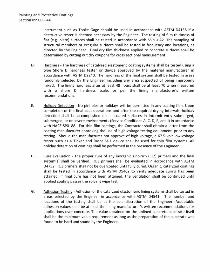
Painting and Protective Coatings Section 09900 – 44
instrument such as Tooke Gage should be used in accordance with ASTM D4138 if a destructive tester is deemed necessary by the Engineer. The testing of film thickness of flat (e.g. plate) surfaces shall be tested in accordance with SSPC-PA2. The sampling of structural members or irregular surfaces shall be tested in frequency and locations, as directed by the Engineer. Final dry film thickness applied to concrete surfaces shall be determined by cutting out dry coupons for cross sectional measurement.
D. Hardness - The hardness of catalyzed elastomeric coating systems shall be tested using a
type Shore D hardness tester or device approved by the material manufacturer in accordance with ASTM D2240. The hardness of the final system shall be tested in areas randomly selected by the Engineer including any area suspected of being improperly mixed. The lining hardness after at least 48 hours shall be at least 70 when measured with a shore D hardness scale, or per the lining manufacturer’s written recommendations.
E. Holiday Detection - No pinholes or holidays will be permitted in any coating film. Upon
completion of the final coat operations and after the required drying intervals, holiday detection shall be accomplished on all coated surfaces in intermittently submerged, submerged, or or severe environments (Service Conditions A, C, D, E, and I) in accordance with NACE SP0188. For thin film coatings, the Contractor shall obtain a letter from the coating manufacturer approving the use of high-voltage testing equipment, prior to any testing. Should the manufacturer not approve of high-voltage, a 67.5 volt low-voltage tester such as a Tinker and Rasor M-1 device shall be used for thin film systems. All holiday detection of coatings shall be performed in the presence of the Engineer.
F. Cure Evaluation - The proper cure of any inorganic zinc-rich (IOZ) primers and the final
system(s) shall be verified. IOZ primers shall be evaluated in accordance with ASTM D4752. IOZ primers shall not be overcoated until fully cured. Organic, catalyzed coatings shall be tested in accordance with ASTM D5402 to verify adequate curing has been attained. If final cure has not been attained, the ventilation shall be continued until applied coating passes the solvent wipe test.
G. Adhesion Testing - Adhesion of the catalyzed elastomeric lining systems shall be tested in
areas selected by the Engineer in accordance with ASTM D4541. The number and locations of the testing shall be at the sole discretion of the Engineer. Acceptable adhesion values shall be at least the lining manufacturer’s written recommendations for applications over concrete. The value obtained on the unlined concrete substrate itself shall be the minimum value requirement as long as the preparation of the substrate was found to be hard and sound by the Engineer.

Painting and Protective Coatings Section 09900 – 45
3.11 CLEAN-UP
A. Upon completion of the work, all staging, scaffolding and containers shall be removed
from the site or destroyed in a manner approved by the Engineer. Coating or paint spots upon adjacent surfaces shall be removed and the entire jobsite cleaned. All damage to surfaces resulting from the work of this section shall be cleaned, repaired, or refinished to the complete satisfaction of the Engineer at no cost to the Owner.
3.12 OMISSIONS A. Care has been taken to delineate herein those surfaces to be coated. However, if coating
or painting requirements have been inadvertently omitted from this section or any other section of the specifications, it is intended that all surfaces, unless specifically exempted herein, shall receive a first-class protective coating or paint system equal to that given the same type surface pursuant to these specifications.
3.13 COLOR CODE SCHEDULE Item Color Code Label
Aeration Air Light Green AA
Belt Press Return Water Gray BPRW
Building Drain NA BD
Compressed Air Light Green w/Yellow CA
Chlorinated Effluent Blue CE
Chlorine Gas Yellow/Green Band CG
Chlorine Solution Yellow CS
Cold Digested Sludge Brown CSL
Diesel Fuel Yellow DF
Digested Sludge Brown DSL
Digested Sludge Transfer Brown XSL
Digester Gs Red DG
Drain NA D
Electrical Panel (within bldg) ANSI 61 - Gray --
Electrical Conduit and Equipment (except panels)
White (Sherwin Williams F65W1) --
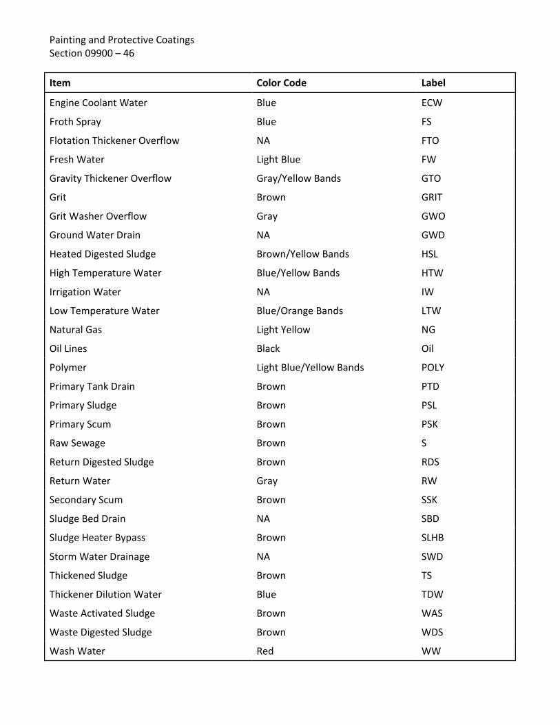
Painting and Protective Coatings Section 09900 – 46 Item Color Code Label
Engine Coolant Water Blue ECW
Froth Spray Blue FS
Flotation Thickener Overflow NA FTO
Fresh Water Light Blue FW
Gravity Thickener Overflow Gray/Yellow Bands GTO
Grit Brown GRIT
Grit Washer Overflow Gray GWO
Ground Water Drain NA GWD
Heated Digested Sludge Brown/Yellow Bands HSL
High Temperature Water Blue/Yellow Bands HTW
Irrigation Water NA IW
Low Temperature Water Blue/Orange Bands LTW
Natural Gas Light Yellow NG
Oil Lines Black Oil
Polymer Light Blue/Yellow Bands POLY
Primary Tank Drain Brown PTD
Primary Sludge Brown PSL
Primary Scum Brown PSK
Raw Sewage Brown S
Return Digested Sludge Brown RDS
Return Water Gray RW
Secondary Scum Brown SSK
Sludge Bed Drain NA SBD
Sludge Heater Bypass Brown SLHB
Storm Water Drainage NA SWD
Thickened Sludge Brown TS
Thickener Dilution Water Blue TDW
Waste Activated Sludge Brown WAS
Waste Digested Sludge Brown WDS
Wash Water Red WW

Painting and Protective Coatings Section 09900 – 47
Architectural System
Descriptive Color Code
Manufacturers' Paint Designation
PLANT BUILDINGS:
General Surface Tan Rustoleum #865 (Dunes Tan)
Trim & Doors Dark Brown Rustoleum #977 (Chestnut Brown)
Walls (metal) Yellow-White Dunn-Edwards #CH-60B (Parchment)
END OF SECTION 09900

Painting and Protective Coatings Section 09900 – 48
[PAGE LEFT INTENTIONALLY BLANK]

Rev: 09/06/16
SPECIFICATIONS - DETAILED PROVISIONS Section 15064 - Plastic (PVC) Pressure Water Pipe & Fittings
C O N T E N T S
PART 1 - GENERAL ............................................................................................................................. 1
1.01 REQUIREMENT .......................................................................................................................... 1 1.02 DELIVERY ................................................................................................................................... 1 1.03 QUALITY ASSURANCE ................................................................................................................ 1 1.04 MEASUREMENT AND PAYMENT ............................................................................................... 1
PART 2 - PRODUCTS AND MATERIALS ................................................................................................ 2 2.01 TYPE OF PVC PIPE ...................................................................................................................... 2 2.02 PIPE CLASS OR WORKING PRESSURE ........................................................................................ 2 2.03 TYPE OF FITTING ....................................................................................................................... 2 2.04 RESTRAINED SYSTEM ................................................................................................................ 2 2.05 SERVICE CONNECTION OUTLETS ............................................................................................... 2 2.06 POLYETHYLENE ENCASEMENT .................................................................................................. 3
PART 3 - EXECUTION ......................................................................................................................... 3 3.01 FACTORY TESTING ..................................................................................................................... 3 3.02 INSTALLATION ........................................................................................................................... 3


Plastic (PVC) Pressure Water Pipe & Fittings Section 15064 – 1
SECTION 15064 PLASTIC (PVC) PRESSURE WATER PIPE & FITTINGS
PART 1 - GENERAL
1.01 REQUIREMENT It is required that the Contractor shall furnish, deliver, unload and string along the trench site, all pipe and material as hereinafter described in the specifications. All fabrication, workmanship, material and testing of pipe shall conform to the latest revision of the specifications.
1.02 DELIVERY
A. Transport, deliver, unload, store and handle all materials in a manner to prevent damage to the materials or the work.
B. All damaged, broken or otherwise defective materials will be rejected.
C. Store all circular rubber gaskets and special lubricants in packaged materials with the manufacturer's name, brand and all other applicable data plainly marked thereon.
1.03 QUALITY ASSURANCE Unless otherwise specified, all work specified herein and as shown on the drawings shall conform to the applicable requirements of the latest revision of the following standards. Unless specifically stated otherwise, the most stringent requirement will govern when there is a conflict.
A. AWWA C-900. American Water Works Association (AWWA) C-900 standard for polyvinyl chloride (PVC) pressure pipe 4 inches through 60 inches for water.
B. Any pipe showing discoloration, chaulking, checking or other visible damage due to ultraviolet light exposure shall not be accepted by the District.
1.04 MEASUREMENT AND PAYMENT Payment for pipe shall be made on a unit price basis per lineal foot of pipe.

Plastic (PVC) Pressure Water Pipe & Fittings Section 15064 – 2
PART 2 - PRODUCTS AND MATERIALS
2.01 TYPE OF PVC PIPE PVC pipe and fabricated fittings shall be made from virgin PVC resin that has been compounded to provide physical and chemical properties that equal or exceed cell class 12454 as defined in ASTM D1784 providing a hydrostatic design basis (HDB) of 4000 p.s.i. in accordance to AWWA C-900. Pipe shall have cast iron outside diameters. All rubber rings shall be furnished by the pipe manufacturer. These rubber rings (elastomeric gaskets) shall be manufactured to conform with the requirements of ASTM F-477.
2.02 PIPE CLASS OR WORKING PRESSURE AWWA C-900 PVC pipe shall be Pressure Class 235 and shall have a Dimension Ratio of 18.0 (DR-18).
2.03 TYPE OF FITTING Fittings for PVC pipe shall be flanged or bolted mechanical joint or push-on joint ductile or gray iron fittings and shall conform to ANSI/AWWA C110/A21.10 or C153/A21.53, and ANSI/AWWA C111/A21.11. All fittings shall be cement mortar lined and tar (seal) coated in accordance with ANSI/AWWA CI04/A21.4.
2.04 RESTRAINED SYSTEM Restrained Joints shall be provided by a clamping ring and an additional ring designed to seat on the bell end of the pipe. The rings shall be connected with T-Head bolts or rods. Restraining devices shall provide full (360 degree) support around the circumference of the pipe. No point loading shall be permitted. Restraint of mechanical joint fittings shall be provided by a clamping ring installed on the PVC pipe and connected to the mechanical joint fitting with T-Head bolts or rods. Restraining devices shall meet or exceed the requirements of ASTM F-1674 or UNI-Bell B-13 "Recommended Standard Performance Specification for Joint Restrainers for Use with PVC Pipe." Restraining devices shall be UNI-Flange Series 1300 or 1350 or approved equal. All buried steel parts shall be sand blasted in accordance with the coating manufacturer's technical data sheet for "submerged" service and coated with a two coat epoxy. Epoxy shall be Tnemac Series 66 or equal. All bolts and tie rod materials shall be either high strength cast iron containing a minimum of 0.5% copper or high-strength, low alloy steel, as specified in AWWA C-111 for buried mechanical joints.
2.05 SERVICE CONNECTION OUTLETS All service connections to PVC pressure pipe water main shall be constructed with bronze service saddles with CS threads for receiving a bronze corporation stop in accordance with standard drawings. Service saddle shall be Jones, Mueller, or approved equal.

Plastic (PVC) Pressure Water Pipe & Fittings Section 15064 – 3
2.06 POLYETHYLENE ENCASEMENT All ductile or gray iron fittings shall be encased with V-Bio enhanced polyethylene at the time of installation. Polyethylene encasement and installation shall be in accordance with ANSI/AWWA C105.
PART 3 - EXECUTION
3.01 FACTORY TESTING All pipe shall be tested in the United States in accordance with AWWA C900 and certification of the testing shall be furnished to the engineer upon his request prior to delivery. The engineer may be present during physical testing of pipe.
3.02 INSTALLATION PVC pipe shall be installed in accordance with Sections 02718 and 02201 of Eastern Municipal Water District Specifications.
END OF SECTION 15064

Plastic (PVC) Pressure Water Pipe & Fittings Section 15064 – 4
[PAGE LEFT INTENTIONALLY BLANK]

Revised 04/14/16
SPECIFICATIONS - DETAILED PROVISIONS Section 15700 - Heating, Ventilation, and Air Conditioning Equipment
C O N T E N T S
PART 1 - GENERAL ....................................................................................................................... 1
1.01 DESCRIPTION ............................................................................................................... 1 1.02 SPECIFIC PROJECT VENTILATION AND AIR CONDITIONING REQUIREMENTS ....................... 1 1.03 GENERAL REQUIREMENTS ............................................................................................. 1 1.04 SUBMITTALS ................................................................................................................ 2
PART 2 - PRODUCTS ..................................................................................................................... 3 2.01 GENERAL ..................................................................................................................... 3 2.02 WALL LOUVERS ............................................................................................................ 4 2.03 SHEET METAL DUCTWORK AND MISCELLANEOUS ACCESSORIES ....................................... 6 2.04 SUPPLY AND RETURN REGISTERS ................................................................................... 8 2.05 ROOF MOUNTED EXHAUST VENTILATORS, LOW PROFILE TYPE WITH HOOD ...................... 9 2.06 ROOF MOUNTED EXHAUST VENTILATORS, DOWNBLAST TYPE ........................................ 10 2.07 RESTROOM CEILING EXHAUSTER ................................................................................. 11 2.08 PAD MOUNTED AIR CONDITIONING UNIT ..................................................................... 12 2.09 PAD MOUNTED HEAT PUMP UNIT ............................................................................... 13 2.10 WALL MOUNTED AIR CONDITIONING UNIT ................................................................... 14 2.11 EVAPORATIVE COOLER ............................................................................................... 16 2.12 SPLIT-DUCTLESS AIR CONDITIONING SYSTEM ................................................................ 18
PART 3 - EXECUTION .................................................................................................................. 21 3.01 GENERAL ................................................................................................................... 21 3.02 START-UP AND INSTRUCTION ...................................................................................... 22


Heating, Ventilation, and Air Conditioning Equipment
15700 - 1
SECTION 15700 HEATING, VENTILATION, AND
AIR CONDITIONING EQUIPMENT PART 1 - GENERAL 1.01 DESCRIPTION The Contractor shall furnish, install, and test the heating, ventilation, and air conditioning
(HVAC) equipment including ducts, registers, louvers, supply and exhaust ventilators, evaporative coolers, air conditioners, dampers, thermostats, controls and accessories as specified herein and shown on the Drawings.
1.02 SPECIFIC PROJECT VENTILATION AND AIR CONDITIONING REQUIREMENTS Contractor shall furnish and install specific project HVAC equipment as shown on the Drawings
and as specified in Section 15700.1, Detailed Heating, Ventilation and Air Conditioning Equipment.
1.03 GENERAL REQUIREMENTS
A. Ambient Conditions and Elevations Equipment shall be designed to operate at the elevation and ambient conditions shown
on the Drawings and specified in the Special Conditions. B. Dimensional Restrictions Layout dimensions will vary between manufacturers. The layout area indicated on the
Drawings is based on typical equipment. Contractor shall review the Contract Drawings, the manufacturer's layout drawings, and installation requirements and shall make any modifications required for proper installation subject to acceptance by the District.
C. Coordination Equipment furnished and installed under this section shall be fabricated, assembled,
erected, and placed in proper operating condition in full conformity with the Drawings, Specifications, and recommendations of the equipment manufacturer. Contractor shall verify that each component of the system is compatible with all other parts of the system; that all piping, ductwork, materials, equipment, and motor sizes are appropriate; and that all devices necessary for a properly functioning system have been provided.

Heating, Ventilation, and Air Conditioning Equipment 15700 - 2
D. Manufacturers and Local Service Where two or more units of the same class of equipment are required, they shall be the
product of a single manufacturer. However, all the component parts of the system need not be the products of one manufacturer.
Each equipment manufacturer shall have a local service center and shall be able to
provide service within 24 hours. The service center shall be equipped and staffed to service the system and shall maintain a local parts supply. Information on equipment manufacturers' representatives shall be included with the submittals.
1.04 SUBMITTALS
A. Shop Drawings
In accordance with the requirements of the General Conditions, Contractor shall submit complete information, drawings, and technical data for all equipment and components, including, but not limited to, the following:
1. Complete specifications, dimensioned drawings of each equipment unit and
support curb (if applicable), catalog cuts, data sheets, bill or materials, and descriptive literature which shall include make, model, dimensions, weight of equipment, and electrical schematic wiring diagrams (if applicable).
2. Details of unit support and anchorage requirements. 3. Complete performance data, performance curves, and ratings that will indicate
full compliance with the specifications.
4. Control components, including description of control component operations. Equipment wiring diagrams and interconnection diagrams.
5. Detailed information on structural, mechanical, electrical, or other changes or
modifications necessary to adapt equipment and materials to be supplied to the arrangement or details shown on the Drawings.
6. Shipping, unloading, storage, and installation instructions, lifting points, and any
special precautions to be observed during unit storage and installation. B. Operation and Maintenance Manuals Operation and maintenance manuals shall be provided in accordance with the
requirements of the General Conditions, and Detailed Provisions, Specification 01430.

Heating, Ventilation, and Air Conditioning Equipment
15700 - 3
PART 2 - PRODUCTS 2.01 GENERAL
A. Specific Project Requirements
Not all products specified herein are necessarily required for this project. Contractor shall refer to the Drawings and Item 1.02 "Specific Project Ventilation and Air Conditioning Requirements" herein for products required for this project. Said products shall be provided as specified herein and shown on the Drawings.
B. Equipment Manufacture and Fabrication Manufacture and fabrication of equipment shall comply with the requirements of
Section 11005, General Mechanical and Equipment Specifications. C. Drive Units Electric motors, V-belt drives, and safety guards shall be in accordance with the
requirements of Section 11005, General Mechanical and Equipment and Section 16150 Induction Motors Specifications.
D. Electrical Electric motor controls shall be as shown on the Drawings and as specified in Section
16480, Motor Control Centers, Switchboards, and Panelboards, Section 17005, General Instrumentation and Control Components, and Section 17010, Programmable Logic Controller. Motor starters and controls shall be furnished and installed as shown on the Drawings, except for equipment specified to be furnished with factory manufactured control panels.
E. Shop Testing The equipment furnished under this section shall be tested at the factory according to
the standard practice of the manufacturer. Ratings shall be based on tests made in accordance with applicable AMCA, ASHRAE, ARI, NBS, NFPA, and UL Standards.

Heating, Ventilation, and Air Conditioning Equipment 15700 - 4
F. Balance All rotating parts shall be accurately machined and shall be in as nearly perfect
rotational balance as practicable. Excessive vibration shall be sufficient course for rejection of the equipment. The mass of the unit and its distribution shall be such that the resonance at normal operating speeds is avoided. In any case, the maximum measured root-mean-square (rms) value as measured at any point on the equipment shall not exceed those listed in the latest ASHRAE Applications Handbook.
At any operating speed, the ratio of rotative speed to the critical speed of a unit or
components thereof shall be less than 0.8 or more than 1.3. 2.02 WALL LOUVERS A. General 1. Louvers shall be intake or exhaust as shown on the drawings of the fixed (unless
otherwise specified), flat blade, 45° type, having a width of 4" and sized to fit the opening specified.
2. Louvers shall be suitable for mounting in stud wall, with gypsum board and
stucco, concrete walls, or masonry walls as shown on the Drawings. Size, number, and location shall be as shown on the Drawings.
3. Louvers shall be anchored into walls (from inside of building) at corners, top and
side, and bottom and side with wood lag screws or expansion anchors as applicable. Additional anchors shall be provided such that maximum anchorage space shall be 24" O.C.
4. Louvers shall be weatherproofed. All louver edges, including flashing, in contact
with wall surfaces shall be caulked with exterior grade caulking compound. B. Wall Mounted Stationary (Fixed) Louvers 1. Fixed blade (stationary) intake or exhaust louvers shall be flat blade type of
formed steel with blades at 45° angle. Frame and blades shall be minimum 16 gauge galvanized steel.
2. Each louver shall be provided with a removable 1/4" mesh, 23 gauge wire,
galvanized insect screen with galvanized steel frame. Screen shall be attached with screws. Screen shall be located on interior side of wall.

Heating, Ventilation, and Air Conditioning Equipment
15700 - 5
3. Stationary wall louvers shall be Model 609B as manufactured by The Airolite, Co., or equal.
C. Wall Mounted Adjustable Louver 1. Adjustable blade intake or exhaust louvers shall be of formed steel construction
with frame and blade minimum 18 gauge galvanized steel. 2. Blades shall be positioned at 45° when fully opened. Crank handle shall be
provided for adjusting and shall be provided with an extension where wall thickness necessitates.
3. Each louver shall be provided with a removable 1/4" mesh, 23 gauge wire,
galvanized insect screen with galvanized steel frame. Screen shall be attached with screws. Screen shall be located on interior side of wall.
4. Adjustable wall louvers shall be Model AEL-162 as manufactured by Louvers &
Dampers, Inc., or equal. 5. Where shown on the Drawings or specified herein, adjustable louvers shall be
provided with electric motor actuators. Actuators shall be operated by 120 VAC power and shall be provided with spring return to fully open or fully closed as specified.
6. Where shown on the Drawings or specified herein, adjustable louvers shall be
recessed in the wall and be provided with a vandal protection type louver on exterior.
D. Wall Mounted Automatic Gravity Type Louvers 1. Intake and exhaust automatic gravity type louvers shall be suitable for high
velocity and high static pressure and shall automatically open upon operation of the ventilation system or radiator cooling exhaust fan. Louver shall be intake or exhaust as shown on the Drawings and dictated by the ventilation system. Louvers shall consist of 16 gauge galvanized formed steel frame and 14 gauge aluminum tied blades with felt tip edges. Automatic gravity type louvers shall be as manufactured by Louvers & Dampers, Inc., or equal.
2. Intake and exhaust openings shall be provided with weather protection fixed
louvers on exterior face and the gravity louvers on the interior face unless otherwise specified.

Heating, Ventilation, and Air Conditioning Equipment 15700 - 6
E. Wall Mounted Acoustical Louver 1. Formed steel acoustical wall louvers shall be provided where specified or shown
on the Drawings. Construction shall be similar to fixed wall louvers. Noise side of louver shall include Type 703 fiberglass at 3.0 lb/cu ft density covered with 20 gauge perforated galvanized steel, or equal. Minimum noise reduction of 14 dB at octave band No. 3 shall be provided.
2. Each louver shall be provided with a removable 1/4" mesh, 23 gauge wire,
galvanized insect screen with galvanized steel frame. Screen shall be attached with screws. Screen shall be located on interior side of wall.
3. Acoustic louver shall be 8" thick Model ALC-8-101 as manufactured by Louvers &
Dampers, Inc., or equal. 2.03 SHEET METAL DUCTWORK AND MISCELLANEOUS ACCESSORIES A. Construction 1. Ductwork (ducts and fittings) shall be constructed as shown on the Drawings
with airtight joints and seams in accordance with ASHRAE standards and SMACNA Duct Construction Manual. Unless specified otherwise, ductwork shall be fabricated per SMACNA low pressure class, with static pressure rating of 2" w.g. (positive or negative) and suitable for air velocities of up to 2,500 fpm. Ductwork materials shall be galvanized steel per ASTM A527 with coating designation G-90, unless otherwise specified. Minimum duct gauges required are as follows:
Maximum Size Galvanized Steel of Ducts U.S. Standard Gauge 12" and less 24 13" through 30" 22 31" through 54" 20
2. All transverse joints shall be sealed per SMACNA Class C requirements with vinyl
acrylic duct sealant, nonflammable wet or dry, UL listed, with flame spread O, fuel contributed O, and smoke developed O. Gaskets for flanged duct joints shall be 1/4" thick, full faced, closed cell, expanded neoprene sponge.

Heating, Ventilation, and Air Conditioning Equipment
15700 - 7
B. Supports Supports for horizontal ducts shall be galvanized steel angles or double struts with
threaded hanger rods unless specified otherwise. Supports for vertical ducts shall be band iron strap or angle bracket type. Inlet ducts shall be amply braced to withstand maximum negative pressure.
C. Flexible Connectors 1. Flexible duct connections shall be made at each point where the air conditioning
or air handling unit is connected to a duct. Flexible connectors shall be UL listed, waterproof, fire resistant, mildew resistant, air-tight woven fibrous glass cloth, double coated with chloroprene or chlorosulphonated polyethylene, and provided with sheet metal collars. Flexible connectors shall be as manufactured by Ventfabrics, Inc., United McGill, Duro-Dyne Ductmate.
2. Fabric for flexible connections protected from sunlight and the weather shall be
suitable for a temperature range of -20 to 180°F and shall weigh at least 27 ounces per square yard.
3. Fabric for flexible connections exposed to sunlight or the weather shall be
suitable for a temperature range of -10 to 250°F and shall weigh at least 24 ounces per square yard.
D. Volume Control Dampers Where shown on the Drawings, provide factory fabricated volume control dampers with
locking quadrant and 8" maximum blade width. Volume control dampers shall be Ruskin MD-25 or MD-35 (rectangular), MDRS-25 (round), or equal. Dampers shall be manually adjusted for air balancing.
E. Insulation and Weatherproofing 1. All exterior ductwork shall be provided with an insulation and weatherproofing
system suitable for outdoor conditions, including direct sunlight and rain. The insulation system shall be installed in strict accordance with the manufacturer's printed recommendations.

Heating, Ventilation, and Air Conditioning Equipment 15700 - 8
2. Insulation material shall be a flexible, closed-cell, 1” thick (minimum) elastomeric insulation in sheet form. The insulation material shall be AP Armaflex SA, as manufactured by Armacell. Insulation material shall have a maximum thermal conductivity of 0.28 BTU-in/hr-sq ft-deg-F at 90°F. Insulation material shall have a flame-spread index of less than 25 and a smoke-developed index of less than 50.
3. Adhesive shall be a contact adhesive, Armaflex 520 as manufactured by
Armacell. 4. Sheet insulation shall be adhered directly to clean, oil-free duct surfaces with a
full coverage of contact adhesive. The duct insulation shall be constructed from the bottom up, with the top insulation sized to extend over the side insulation to form a watershed. Butt-edge seams shall be adhered using contact adhesive by the compression fit method to allow for expansion/contraction. Standing metal duct seams shall be insulated with the same insulation thickness as installed on the duct surface. Seams shall be covered using strips of sheet insulation. Standing seams shall be adhered using contact adhesive. Insulation seams shall be staggered when applying multiple layers of insulation.
5. All insulated ductwork shall be weatherproofed with 0.020" thick
stucco-embossed aluminum jacketing. Jacketing shall be manufactured from ASTM B-209, Temper H-14 aluminum alloy with factory bonded moisture barrier. Aluminum jacketing shall be installed with a 2" overlap at longitudinal seams and end joints. Secure jacket with stainless steel sheet metal screws at 6" on center along seams and at end joints. Overlapped longitudinal seams shall be arranged to shed water. All joints shall be sealed with a silicone mastic to provide a continuous weather-tight joint. Strapping shall be 3/4" wide aluminum or stainless steel. Aluminum jacketing shall be as manufactured by Pabco Childers Metals, RPR Products, Inc., or equal.
2.04 SUPPLY AND RETURN REGISTERS A. General Supply and return registers shall be constructed of Type 304 stainless steel. Unless
specified otherwise, supply registers shall be double deflection with front deflection blades parallel to the short dimension of the register and return registers shall be single deflection with deflection blades parallel to the short dimension of the register. Registers shall be as manufactured by Titus, A-J Manufacturing Co., or equal.

Heating, Ventilation, and Air Conditioning Equipment
15700 - 9
B. Construction 1. Registers shall be provided with a 1-1/4" wide border on all sides for flush
surface mounting. Borders shall be provided with continuous foam gaskets. Screw holes shall be countersunk for a neat appearance. Corners shall be welded with full penetration resistance welds. Where registers are shown to be mounted in exposed ductwork, register frames shall not extend beyond the sides of the ductwork. Register manufacturer shall coordinate register size and mounting with ductwork manufacturer.
2. Deflection blades shall be contoured and spaced on 3/4" centers. Blades shall
have friction pivots on both ends to allow individual blade adjustment without loosening or rattling. Plastic blade pivots are not acceptable.
3. Each register shall be provided with an opposed blade volume damper
constructed of heavy gauge Type 304 stainless steel. Damper shall be operable from face of register.
4. Registers shall be unpainted and furnished with a uniform satin (mill) finish.
2.05 ROOF MOUNTED EXHAUST VENTILATORS, LOW PROFILE TYPE WITH HOOD
A. Roof exhaust ventilators shall be of low profile design with extruded aluminum hood of the centrifugal, belt-driven type. Construction of the fan housing shall be of heavy gauge aluminum.
B. The fan wheel shall be all-aluminum of the centrifugal blower type featuring backward
inclined blades and a tapered inlet shroud. Wheels shall be statically and dynamically balanced.

Heating, Ventilation, and Air Conditioning Equipment 15700 - 10
C. Motors shall be of the heavy duty, permanently lubricated, sealed ball bearing type. Drives shall be sized for 165% of motor horsepower capabilities and of the cast iron type, keyed to the fan and motor shafts. Variable pitch drives shall be standard. Fan shaft shall be of steel construction, turned, ground, and polished to precise tolerances in relationship to the hub and bearings. Drive belts shall be of the oil-resistant, non-static, non-sparking type with life expectancy of over 24,000 hours. Bearings shall be flanged and of the permanently lubricated, permanently sealed, ball bearing type capable of over 200,000 hours bearing life. The entire drive assembly and wheel shall be removable, as a complete unit, from the support structure without disassembling the external fan housing. The complete drive assembly shall be mounted on rubber vibration isolation. Direct drive units shall be of identical construction as belt drive units, except for drives, belts, and fan shaft bearings. Fans shall be licensed to bear the AMCA ratings seal for air and sound performance. Motor voltage and phase shall be as shown on the Drawings and as specified in Part 1.02 herein.
D. Fans shall be Model HLC-B as manufactured by Loren Cook, Model LD/LB as
manufactured by Greenheck, or equal. Each fan shall have the performance as specified in Part 1.02 herein.
E. Unless shown otherwise on the Drawings, roof exhaust ventilators shall be mounted on
prefabricated metal roof curbs. Prefabricated roof curbs shall be a minimum 8" high, constructed of minimum 18-gauge galvanized steel, with 2" x 2" treated wood nailer, 1" (minimum) semi-rigid thermal insulation, and 3" x 3" integral cant. Exhaust ventilators shall be installed level on pitched roofs, and roof curbs shall be sized to accommodate the roof pitch shown on the Drawings. Prefabricated roof curbs shall be model SC as manufactured by Louver & Dampers, Inc., or equal. Ventilators shall be provided with automatic gravity backdraft dampers.
2.06 ROOF MOUNTED EXHAUST VENTILATORS, DOWNBLAST TYPE
A. Downblast type exhaust ventilators shall be roof-mounted with a belt-driven centrifugal fan wheel. Fan enclosure shall be spun aluminum, mushroom style.
B. Centrifugal fan wheel shall be backward inclined, aluminum construction. Wheel shall
be balanced in accordance with AMCA Standard 204-96, Balance Quality and Vibration Levels for Fans.
C. Aluminum enclosure structural components shall be constructed of minimum 16 gauge
marine alloy aluminum and shall be bolted to a rigid aluminum support structure. Aluminum base shall have continuously welded curb cap corners. The motor shall be enclosed in a weather-tight compartment, separated from the exhaust airstream.

Heating, Ventilation, and Air Conditioning Equipment
15700 - 11
D. Motors shall be of the heavy duty, permanently lubricated, sealed ball bearing type. Drives shall be sized for 150% of motor horsepower capabilities and of cast iron construction. Bearings shall be heavy duty regreasable ball type in a cast-iron pillowblock housing selected for a minimum L50 life in excess of 200,000 hours at maximum cataloged operating speed. The motor, bearings, and drives shall be mounted on a minimum 14-gauge steel power assembly, isolated from the unit structure with rubber vibration isolators. Fan shaft shall be of steel construction, turned, ground, and polished to precise tolerances in relationship to the hub and bearings. Motor voltage and phase shall be as shown on the Drawings and as specified in Part 1.02 herein.
E. Fans shall be Type ACE as manufactured by Loren Cook Company, Type GB as
manufactured by Greenheck, or equal. Each fan shall have the performance as specified in Part 1.02 herein.
F. Unless shown otherwise on the Drawings, roof exhaust ventilators shall be mounted on
prefabricated metal roof curbs. Prefabricated roof curbs shall be a minimum 8" high, constructed of minimum 18-gauge galvanized steel, with 2" x 2" treated wood nailer, 1" (minimum) semi-rigid thermal insulation, and 3" x 3" integral cant. Exhaust ventilators shall be installed level on pitched roofs, and roof curbs shall be sized to accommodate the roof pitch shown on the Drawings. Prefabricated roof curbs shall be model SC as manufactured by Louver & Dampers, Inc., or equal. Ventilators shall be provided with automatic gravity backdraft dampers.
2.07 RESTROOM CEILING EXHAUSTER
A. Contractor shall furnish and install restroom exhausters as specified herein and as shown on the Drawings. Exhausters shall be ceiling mount type, direct driven, UL listed, centrifugal exhaust fans.
B. Fan housing shall be minimum 20 gauge galvanized steel and acoustically insulated.
Blower and motor assembly shall be mounted to a minimum 14 gauge reinforcing channel and shall be easily removable from the housing. Motor shall be mounted on rubber vibration isolators. Unit shall be supplied with integral wiring box and receptacle. The outlet duct collar shall include a reinforced aluminum damper with continuous aluminum hinge rod and brass bushings. Inlet shall be provided with an aluminum grill.
C. Blower wheel shall be centrifugal forward curve type, constructed of galvanized steel.
Wheel shall be balanced in accordance with AMCA Standard 204-96. D. Motor shall be open drip-proof type with permanently lubricated sealed bearings and
built-in thermal overload protection.

Heating, Ventilation, and Air Conditioning Equipment 15700 - 12
E. Fans shall be Gemini GC type as manufactured by Loren Cook, or equal. F. Unless shown otherwise on the Drawings, ceiling exhausters shall be provided with
hanging isolator hardware, including all-thread rods, isolator bushings, and appurtenances.
2.08 PAD MOUNTED AIR CONDITIONING UNIT
A. A commercial pad mounted packaged air conditioning unit shall be provided for room cooling as shown on the Drawings. Air conditioning unit shall be factory assembled, piped, internally wired, and fully charged. Unit shall be UL listed and carry UL label. Unit shall be factory run tested to check cooling operation, fan and blower rotation, and control sequence. Unit shall be designed for pad mounted installations.
B. The packaged unit shall be a 1-phase, 230V (or 3-phase, 460V) 60 Hz horizontal airflow
model as required per Part 1.02 herein, and shall be rated for a minimum total cooling capacity as specified in Part 1.02, with a minimum Seasonal Energy Efficiency Ratio (SEER) of 13. Packaged unit shall be equipped with the following components: compressor, refrigerant circuit, indoor/outdoor coil and fan, return air filter and frame, and system controls.
C. All components shall be mounted in a galvanized steel cabinet with a baked-on enamel
finish. Access panels, removable top cover, knockouts for utility and control connections, and coil guards shall be a part of the cabinet.
D. Coils shall be constructed with aluminum fins mechanically bonded to internally grooved
copper tubes. Coils shall be provided with a balanced port thermal expansion valve to provide optimal performance over the application range. Coils shall be pressure and leak tested to 450 psig. An epoxy modified, phenolic dip coating shall be provided for enhanced corrosion protection.
E. The compressor shall be a hermetically sealed, high efficiency compressor with internal
pressure relief and internal over-current and over-temperature protection. Motors for indoor air and outdoor fans shall be permanently lubricated and have built-in thermal overload protection. Indoor air fan (blower) shall provide a minimum air flow (cfm) as specified in Part 1.02 herein.

Heating, Ventilation, and Air Conditioning Equipment
15700 - 13
F. The air conditioning unit shall be as manufactured by Trane, or equal. The air conditioning unit shall be provided with the following accessories: internal filter frame and pleated air filter (air filter clean resistance per manufacturer's recommendations), standard indoor thermostat as recommended by manufacturer, and a NEMA 3R, 240V, 1-phase or 480V, 3-phase (per Part 1.02 herein) air conditioning fused disconnect switch with 120V, 1-phase, GFI receptacle. A minimum of three (3) spare air filters shall be furnished for each air conditioner.
G. The air conditioning unit shall be installed in accordance with the manufacturer's
printed installation instructions. Electrical connections to the unit shall be made with flexible liquid-tight conduit and weather-tight fittings. Condensate drain piping shall be copper and be fabricated with a trap and cleanout plug. Disconnect switch shall be mounted on the air conditioning unit. The unit shall be anchored to the concrete support slab with vibration isolation pads and Type 316 stainless steel anchors (size and embedment per air conditioning unit manufacturer).
H. Contractor shall coordinate selection of packaged unit and accessories with associated
supply/return ductwork to provide a complete and operable air conditioning system.
2.09 PAD MOUNTED HEAT PUMP UNIT
A. A commercial pad-mounted packaged heat pump unit shall be provided for room cooling/heating as shown on the Drawings, and as specified herein. Heat pump unit shall be factory assembled, piped, internally wired, and fully charged. Unit shall be UL listed and carry UL label. Unit shall be factory run tested to check cooling/heating operation, fan and blower rotation, and control sequence. Unit shall be designed for ground level installation.
B. The packaged heat pump shall be a 1-phase, 230V (or 3-phase, 460V), 60 Hz horizontal
airflow model as required per Part 1.02 herein and shall be rated for a minimum cooling/heating capacity as specified in Part 1.02, with a minimum Seasonal Energy Efficiency Ratio (SEER) of 13. Packaged unit shall be equipped with the following components: compressor, refrigerant circuit, indoor/outdoor coil and fan, return air filter and frame, and system controls.
C. All components shall be mounted in a galvanized steel cabinet with a baked-on enamel
finish. Access panels, removable top cover, knockouts for utility and control connections, and coil guards shall be a part of the cabinet.

Heating, Ventilation, and Air Conditioning Equipment 15700 - 14
D. Coils shall be constructed with aluminum fins mechanically bonded to internally grooved copper tubes. Coils shall be provided with a balanced port thermal expansion valve to provide optimal performance over the application range. Coils shall be pressure and leak tested to 450 psig. An epoxy modified, phenolic dip coating shall be provided for enhanced corrosion protection.
E. The compressor shall be a hermetically sealed, high efficiency compressor with internal
pressure relief and internal over-current and over-temperature protection. Motors for indoor air and outdoor fans shall be permanently lubricated and have built-in thermal overload protection. Indoor air fan (blower) shall provide a minimum airflow (cfm) as specified in Part 1.02 herein.
F. The packaged heat pump unit shall be as manufactured by Trane, or equal. The
packaged heat pump shall be provided with the following accessories: internal filter frame and pleated air filter (air filter clean resistance per manufacturer's recommendations), rubber vibration isolation pads, standard indoor thermostat, and a NEMA 3R, 240V, 1-phase or 480V, 3-phase, fused disconnect switch with 120V, 1-phase, GFI receptacle. A minimum of three (3) spare air filters shall be furnished.
G. The packaged heat pump shall be installed in accordance with the manufacturer's
printed installation instructions. Electrical connections to the unit shall be made with flexible liquid-tight conduit and weather-tight fittings. Condensate drain piping shall be copper and be fabricated with a trap and cleanout plug. Disconnect switch shall be mounted on the packaged heat pump unit. The heat pump shall be anchored to the concrete support slab with vibration isolation pads and Type 316 stainless steel anchors (size and embedment per heat pump manufacturer).
H. Contractor shall coordinate selection of packaged unit and accessories with associated
supply/return ductwork and structural roof framing and provide a complete and operable heat pump system.
I. Contractor shall provide volume control dampeners as necessary and also where shown
on the Drawings to achieve air flow splits as specified.
2.10 WALL MOUNTED AIR CONDITIONING UNIT
A. A commercial wall mounted packaged air conditioning unit shall be provided for room cooling as shown on the Drawings. Air conditioning unit shall be factory assembled, piped, internally wired, and fully charged. Unit shall be Intertek ETL listed. Unit shall be factory run tested to check cooling operation, condenser fan and blower rotation, and control sequence. Unit shall be designed for wall mounting installation.

Heating, Ventilation, and Air Conditioning Equipment
15700 - 15
B. The packaged unit shall be a 1-phase, 230V, or 3-phase, 460V, 60 Hz horizontal airflow, through-wall, model and shall be rated for a minimum total cooling capacity as specified in Part 1.02 herein, with a minimum Energy Efficiency Ratio (EER) of 10.0. Packaged unit shall be equipped with the following components: compressor, blower assembly, condenser fan, phenolic epoxy coated condenser coil, phenolic epoxy coated evaporator coil, refrigerant circuit, return air filter and frame, and system controls.
C. All components shall be mounted in a weather-resistant galvanized steel cabinet (20-
gauge minimum thickness) with a baked-on polyester enamel finish. Lower base shall be 16-gauge (minimum) galvanized steel. The cabinet shall be provided with a sloped top and rain flashing. The cabinet shall be provided with full length side mounting brackets that are integral to the cabinet frame. Cooling section shall be fully insulated with minimum 1" thick fiberglass. Access panels, removable top cover, knockouts for utility and control connections, and coil guards shall be a part of the cabinet.
D. The refrigeration system shall include a high efficiency scroll compressor, mounted on
rubber pads. 3-phase compressors shall be provided with protection against phase reversal and phase failure that will prevent the compressor from operating when one of these conditions occurs. The refrigeration circuit shall be provided with factory installed high and low pressure controls and liquid line filter dryer. The refrigeration control shall be a factory installed capillary tube.
E. The condenser fan, motor, and shroud shall be configured for easy slide-out removal. F. The indoor blower motor shall be high efficiency, permanent split capacitor (PSC) type.
The blower motor shall be provided with protection against overload. Blower assembly shall include twin wheels with forward curve blades.
G. The control system shall include a current limiting low-voltage transformer, on and off
time delay circuits to prevent rapid compressor short cycling, low pressure bypass to prevent nuisance tripping during low temperature startup, and one (1) alarm output relay.
H. The electrical control panel shall be configured for right-side or left-side access as
specified in Part 1.02, herein. I. When specified in Part 1.02 herein, or shown on the Drawings, packaged units shall be
provided with factory installed electric resistance heaters (rating as specified). Heater shall include automatic safety limit and thermal cut-off controls. Packaged units with heaters shall be provided with a factory installed circuit breaker (230 VAC models) or rotary disconnect (460 VAC models). Circuit breakers and rotary disconnects shall be provided with a lockable, hinged access covers.
Heating, Ventilation, and Air Conditioning Equipment 15700 - 16
J. When specified in Part 1.02 herein, or shown on the Drawings, packaged units shall be provided with options and accessories, including barometric fresh air dampener, motorized fresh air dampener, commercial room ventilator, economizer, or energy recovery ventilator.
K. The air conditioning unit shall be provided with a NEMA 3R, 240V, 1-phase or 480V, 3-
phase, fused disconnect switch with 120V, 1-phase, GFI receptacle. L. The air conditioning unit shall be installed in accordance with the manufacturer's
printed installation instructions. The packaged unit shall be wall mounted with Type 316 stainless steel anchors bolts (size and embedment per packaged unit manufacturer).
M. Electrical connections to the unit shall be made with flexible liquid-tight conduit and
weather-tight fittings. Disconnect switch shall be mounted on air conditioning unit or alternately mounted on adjacent building wall.
N. Contractor shall coordinate selection of packaged unit and accessories with associated
supply/return ductwork to provide a complete and operable air conditioning system. O. The packaged unit shall be provided with a 5 year parts warranty. P. The wall mounted packaged air conditioning unit shall be Series WAA (right-side control
panel) or WLA (left-side control panel) as manufactured by Bard, or equal.
2.11 EVAPORATIVE COOLER
A. A commercial self-contained horizontal discharge, single housing, direct evaporative cooler, including fan section, media, water delivery system, and necessary appurtenances shall be provided for room cooling as shown on the Drawings, and as specified herein.
B. The direct evaporative cooler shall be the wet pad, recirculating type suitable for
connection to duct system or for through wall installation. C. Evaporative coolers and accessories shall be designed to operate continuously. Each
complete unit shall be AMCA certified in conformance with AMCA Standard 210. Certified performance data for all evaporative coolers shall be obtained from tests made in AMCA-approved laboratories.
D. Outside air shall be drawn through the wet evaporative cooler with the air handling unit
supply fan. The cooler shall be located within the air handling unit downstream of an intake filter and a heating coil and upstream of the supply fan. A pump shall circulate water through the cooler.

Heating, Ventilation, and Air Conditioning Equipment
15700 - 17
E. The packaged unit shall be 1 phase, 230V (or 3 phase, 460V) 60 Hz, horizontal air flow model as required per Part 1.02 herein, and shall be rated for minimum air flow, static pressure, media face velocity and media evaporation efficiency.
F. Housing for the entire unit shall be constructed of Type 316 stainless steel in one piece
with steel support frame and lifting lugs. Hinged access panels shall allow for access and removal of all internal components from a single side. Casing shall be insulated with 1 inch of 1-1/2-pound per cubic foot density neoprene coated NFPA-90 approved acoustical fiberglass insulation.
G. The fan section shall have a horizontal discharge with a flange or other provision to
connect sheet metal ductwork as shown on the Drawings. The fan shall be centrifugal type with lubricable bearings on each end. Fan motor shall be totally enclosed fan cooled type and shall be sized to be non-overloading on all parts of the fan curve. Fan shall be belt-driven with adjustable sheave on the motor. Manufacturer’s standard vibration isolators shall be provided under the fan and motor, and neoprene flex connectors shall be provided between the fan discharge and the cabinet.
H. The wet section of the evaporative cooler shall be welded or mechanically attached to
the fan section and shall be supported across its entire width by same support frame. Internal components of the wet section shall include the cooling media, water delivery system, internal plumbing, make-up water valve, overflow, and drain fittings.
I. The sump shall be stainless steel, leak-proof with welded corners and joints. A media
support channel shall extend across the full width of the media and provide for water to flow from the media into the sump. Sump shall be provided with stainless steel couplers for connecting make-up water, overflow, and drain.
J. An air bypass inhibitor plate shall be provided between the media and the sump to
prevent any untreated air flow under the media. K. The water distribution system shall include a recirculating pump with mechanical float
valve assembly to maintain water level in the sump. An adjustable bleed-off system with metering valve and all required piping and valves shall be provided. The internal plumbing shall include a PVC Schedule 80 header pipe with drilled orifice holes to spray water upward to a stainless steel splash plate that evenly distributes the water over the cooling media. A PVC union shall be provided in the riser pipe below the header to facilitate removal of the header pipe.

Heating, Ventilation, and Air Conditioning Equipment 15700 - 18
L. Cooling media shall be rigid, 12-inch deep modules of cellulose evaporation material. Modules shall have at least 120 square feet of evaporative surface area per cubic foot of media. Media shall develop a saturation efficiency of not less than 90 percent and a maximum air pressure drop of 0.315 inches water column at 500 feet per minute face velocity.
M. Power to the packaged unit shall be through a single feed and a fused disconnect
located on the housing, and a starter and separate relay to control water distribution. Hand-Off-Auto switch and pilot lights shall also be mounted on the housing in a NEMA 3R enclosure.
N. The evaporative cooler shall be controlled by the room air handling unit thermostat.
On a high temperature signal from the thermostat, the unit’s automatic fill and drain kit shall fill the sump tank and begin the spraying and evaporation. When room temperature drops to the low set point on the thermostat, the unit’s automatic fill and drain kit shall drain the sump tank allowing the evaporative media to dry. The automatic fill and drain kit shall consist of two solenoid valves, fill and drain switch, time clock, and freeze stat.
O. Evaporated cooler shall be manufactured by Premier Industries, Bessamaire, or equal.
2.12 SPLIT-DUCTLESS AIR CONDITIONING SYSTEM
A. A split-ductless air conditioning system shall be provided for room cooling as shown on the Drawings. Air conditioning system components shall be factory assembled, piped, internally wired, and fully charged. The air conditioning system shall be Intertek ETL listed. The air conditioning system shall be factory run tested to check cooling operation, operation of internal components, and control sequence.
B. The air conditioning system shall be a 1 phase, 230 volt, 60 Hz system and shall be rated
for a minimum total cooling capacity as specified in Part 1.02, herein. The air conditioning system shall be provided with a single indoor unit or multiple indoor units as specified in Part 1.02, herein, or as shown on the Drawings. When specified herein or shown on the Drawings, the air conditioning system shall be provided with a heat pump system (each indoor unit) rated for a minimum total heating capacity as specified in Part 1.02, herein.
C. The air conditioning system shall have a minimum Seasonal Energy Efficiency Ratio
(SEER) of 14.0.

Heating, Ventilation, and Air Conditioning Equipment
15700 - 19
D. The air conditioning system shall be equipped with the following components: floor mounted outdoor unit, wall mounted or ceiling suspended indoor unit(s), refrigerant piping between the indoor and outdoor unit(s), control wiring between the indoor and outdoor unit(s), condensate drain piping for indoor unit(s) to outside of building, and wired wall mounted controller(s).
E. Outdoor Unit
1. The outdoor unit shall include a direct drive propeller fan(s), fan motor (one (1) motor per fan), factory pressure tested heat exchanger (condenser) coil, compressor, refrigerant accumulator on the suction side of the compressor, control circuit board, wiring, and piping. Air shall discharge horizontally form the outdoor unit.
2. The coil shall be constructed with lanced or corrugated aluminum plate fins
attached to copper tubing. 3. The fan shall be provided with permanently lubricated shaft bearings. 4. Refrigerant flow between the outdoor unit and indoor unit shall be regulated by
an electronically controlled expansion valve. One (1) valve shall be provided for each indoor unit. Branch box(es) shall be provided as required by the manufacturer for housing the expansion valve(s) external to the outdoor unit.
5. The compressor shall be hermetically sealed, inverter driven, variable speed, and
dual rotary type. The compressor shall be provided with internal thermal overload protection and mounted on vibration isolation pads.
6. The outdoor unit shall be capable of monitoring ambient temperature,
condenser coil temperature, and refrigerant discharge temperature. 7. The outdoor unit enclosure shall be a weather-resistant bonderized galvanized
steel cabinet with an electrostatically applied, thermally fused polyester coating. All assembly hardware shall be weather-resistant and enclosure shall be provided with integral mounting feet.

Heating, Ventilation, and Air Conditioning Equipment 15700 - 20
F. Indoor Unit(s)
1. Each indoor unit shall include a line-flow or double inlet forward curve radial fan(s) direct driven by a single fan motor, factory pressure tested heat exchanger (evaporator) coil, easily removable return air filter, corrosion resistant condensate drain pan, control circuit board, wiring, and piping housed in a high strength molded plastic or corrosion resistant coated metallic enclosure. Air shall discharge horizontally from the indoor unit(s).
2. The coil shall be constructed with smooth aluminum plate fins attached to
copper tubing. 3. The fan(s) shall be statically and dynamically balanced and provided with a
permanently lubricated shaft bearing. The fan(s) shall be capable of operating at a minimum of three (3) selectable fixed speeds or operating in automatic (automatically vary speed).
4. Each indoor unit shall include motorized, multi-position horizontal louvers to
adjust air flow up and down, and manually or motorized adjustable vertical vanes to adjust air flow left and right.
5. Each indoor unit shall have a self-diagnostic function, time delay start function,
and auto restart function after power interruption. Each indoor unit shall be capable of monitoring indoor room temperature and evaporator coil temperature.
6. Each indoor unit shall be purged with dry air in the factory prior to shipment.
7. Each indoor unit shall be powered directly from the outdoor unit.
G. Contractor shall coordinate selection of indoor unit(s) and outdoor unit to provide a complete and operable air conditioning system.
H. Contractor shall install all interconnection control and power wiring between the indoor
and outdoor units (and branch boxes if applicable) as required to provide a complete functioning air conditioning system. The control wiring shall be provided by the manufacturer of the air conditioning system to ensure unit compatibility.
I. Contractor shall install all interconnection refrigerant piping between the indoor and
outdoor units as required to provide a complete functioning air conditioning system. The refrigerant piping shall be annealed, refrigeration grade, seamless, copper tubing, AC/R type, meeting the requirements of ASTM B280. The refrigeration piping shall be provided with insulation meeting the requirements of Part 2.03E, herein.

Heating, Ventilation, and Air Conditioning Equipment
15700 - 21
J. Contractor shall install 3/4 inch diameter condensate drain lines from indoor unit(s) to the exterior of building. Unless specified otherwise, condensate drain lines shall be constructed of Schedule 40 PVC. Condensate drain lines shall be installed with 2% minimum slope towards drain point and said points shall be located 6 inches above the outdoor finished grade. Condensate drain lines shall be supported by strut channel type pipe supports.
K. The indoor and outdoor units shall be installed in accordance with the manufacturer's
printed installation instructions. All mounting hardware shall be Type 316 stainless steel. Size and embedment of anchor bolts for outdoor units and wall mounted indoor units shall be determined by the manufacturer.
L. Where interconnection control and power wiring, interconnection refrigerant piping,
and condensate drain piping penetrate building walls, Contractor shall provide rubber sleeves through wall penetrations and seal said penetrations with silicone sealant after installation of wiring and piping. Contractor shall provide Diversitech PVC split channel type ducts, or approved equal.
M. The air conditioning system shall be provided with a NEMA 3R, 240V, 1-phase fused
disconnect switch with 120V, 1-phase GFI receptacle mounted adjacent to the outdoor unit.
N. The air conditioning system shall be provided with a 5 year parts and defects warranty
and the compressor shall have a 7 year warranty. O. Split-ductless air conditioning system shall be M-Series or P-Series as manufactured by
Mitsubishi Electric, or equal.
PART 3 - EXECUTION 3.01 GENERAL
A. Contractor shall examine all equipment and material upon arrival at jobsite and determine that it is as specified and approved, and that it is new and in undamaged condition. Contractor shall verify openings (existing and/or new) in structures and ducts are of suitable size for equipment delivered. Contractor shall install all equipment, ductwork, fittings, and appurtenances in strict accordance with manufacturer's printed instructions and approved shop drawings.

Heating, Ventilation, and Air Conditioning Equipment 15700 - 22
B. Contractor shall connect all necessary electrical power including furnishing of all necessary materials in addition to that included in the specified equipment. Wiring materials and installation shall be in accordance with Section 16050, Basic Electrical Materials and Methods, and controls and instrumentation in accordance with Section 17005, General Instrumentation and Control Components, and as shown on the Drawings.
C. Prior to equipment operation, Contractor shall provide initial lubrication of all
mechanical systems, check all belts, pulleys, and other moving parts for alignment and tolerances in accordance with the manufacturer's operating instructions.
3.02 START-UP AND INSTRUCTION
A. Contractor shall arrange for qualified representatives of the manufacturer to inspect the installation and perform start-up of the equipment and to demonstrate required performance to the satisfaction of the District. As a minimum, manufacturer shall field measure air flow rates and specific pressures for each ventilator and air conditioning unit at each operating speed. Manufacturer shall also measure ventilator and air conditioning unit motor amperage, voltage, and power factor for each operating condition. Manufacturer shall furnish all labor and equipment required for field testing and furnish testing results to District in a written report.
B. Contractor shall balance the ventilation and air conditioning systems by adjusting
louvers or grills (unless fixed louvers or grills are specified) to obtain even air flow across a room. Contractor shall furnish calibrated (certification required) air velocity meters for such balancing.
C. After the equipment has been installed, tested, and adjusted, and placed in satisfactory
operating condition, the equipment manufacturer shall provide classroom instruction to District's operating personnel in the use and maintenance of the equipment. Two (2) hours of instruction shall be provided, unless otherwise specified. Contractor shall give the District formal written notice of the proposed instruction period at least two weeks prior to commencement of the instruction period. Scheduled training shall be at a time acceptable to the District and the manufacturer. During this instruction period, the manufacturer shall answer any questions from the operating personnel. The manufacturer's obligation shall be considered ended when he and the District agree that no further instruction is needed.
END OF SECTION

Revised 04/14/16
SPECIFICATIONS - DETAILED PROVISIONS Section 16010 - General Electrical Requirements
C O N T E N T S
PART 1 - GENERAL ....................................................................................................................... 1
1.01 DESCRIPTION .............................................................................................................. 1 1.02 QUALITY ASSURANCE................................................................................................... 1 1.03 UTILITY COMPANY REQUIREMENTS .............................................................................. 5 1.04 SUBMITTALS ............................................................................................................... 6 1.05 PRODUCT DELIVERY, STORAGE, AND HANDLING .......................................................... 10 1.06 COORDINATION OF WORK AND TRADES ..................................................................... 11 1.07 COORDINATION OF THE ELECTRICAL SYSTEM .............................................................. 12 1.08 RELATED WORK SPECIFIED ELSEWHERE ....................................................................... 12 1.09 PERMITS ................................................................................................................... 13 1.10 OUTAGES .................................................................................................................. 13 1.11 AREA CLASSIFICATION DESIGNATIONS ........................................................................ 13 1.12 WARNING SIGNS ....................................................................................................... 14 1.13 GUARANTEE AND WARRANTY .................................................................................... 15
PART 2 - PRODUCTS ................................................................................................................... 15 2.01 MATERIALS AND EQUIPMENT .................................................................................... 15
PART 3 - EXECUTION .................................................................................................................. 16 3.01 GENERAL ................................................................................................................... 16 3.02 ELECTRICAL SUPERVISION .......................................................................................... 16 3.03 INSPECTION .............................................................................................................. 16 3.04 PREPARATION ........................................................................................................... 17 3.05 WORKMANSHIP ........................................................................................................ 17 3.06 PROTECTIVE DEVICE ADJUSTMENTS ............................................................................ 17 3.07 JOB SITE CONDITIONS AND ELECTRICAL DRAWINGS ..................................................... 17 3.08 FIELD TESTING AND QUALITY CONTROL ...................................................................... 19


General Electrical Requirements Section 16010 – 1
SECTION 16010
GENERAL ELECTRICAL REQUIREMENTS PART 1 - GENERAL 1.01 DESCRIPTION
Contractor shall provide all the materials and equipment, and perform all work necessary for the complete execution of the electrical work as indicated on the Drawings, as specified herein, and as specified in other Specification Sections. Miscellaneous appurtenances are not necessarily specified or indicated on the Drawings. Contractor shall provide all labor and materials not specifically indicated on the Drawings or specified in these Specifications, yet required to ensure proper and complete operation of all systems. This Section summarizes the general requirements for electrical work, and forms a part of all other Sections of these Specifications, unless otherwise specified.
1.02 QUALITY ASSURANCE
A. General
1. It is the intent of these Specifications and the Drawings, to secure highest quality in all equipment and materials, and to require first-class workmanship, in order to facilitate trouble free operation and minimum maintenance of the electrical system.
2. All work, including installation, connection, calibration, testing and adjustment,
shall be performed by qualified, experienced personnel who are technically skilled in their trades, are thoroughly instructed, and are competently supervised by a certified electrician in the state of California. The resulting complete installation shall reflect professional quality work, employing industrial standards and methods. Any and all defective material or inferior workmanship shall be corrected immediately to the satisfaction of the District and at no additional cost to the District.
3. All equipment and materials shall be new, listed by UL and bearing the UL label,
unless exception to this requirement is inherent to an individual item specified herein, or exception is otherwise specified, or approved by the District.

General Electrical Requirements Section 16010 – 2
4. Equipment and materials shall be the products of reputable, experienced manufacturers. Singular items in the project shall be the products of the same manufacturer. All equipment and materials shall be of industrial grade and heavy duty construction, shall be of sturdy design and manufacture, and shall be capable of long, reliable, trouble-free service.
5. Contractor shall furnish manufacturer's electrical equipment of the types and
sizes specified which has successfully operated for not less than the past two years, except where specific types are named by manufacturer and catalog number or designation under other Sections of the Contract Documents.
B. Environmental Sustainability
1. All electrical equipment and their enclosures shall be suitable for operation in
the ambient conditions and area classification designations associated with the locations designated in the Contract Documents.
2. All electrical equipment shall be capable of operating successfully at full-rated load, without failure, when the ambient temperature of the air is 50°C. Unless specified otherwise or indicated otherwise on the Drawings, heating and cooling devices shall be provided in order to maintain all electrical equipment and instrumentation devices to within a range equal to 20 percent above the minimum and 20 percent below the maximum of the rated environmental operating ranges. All power wiring and temperature controls for these devices shall be provided by the Contactor.
C. Factory Tests
Factory tests are required for all electrical equipment and assemblies applicable to the specific project. Perform factory tests in accordance with the requirements of the particular equipment specification sections and in accordance with the codes and standards specified as applicable to the equipment. Items to be factory tested shall include, but not be limited to: 1. Motor Control Centers 2. Electrical Service Switchboards and Distribution Switchboards 3. Variable Frequency Drives 4. Solid State Starters 5. Automatic Transfer Switches
General Electrical Requirements Section 16010 – 3
6. Manual Transfer Switches 7. Induction Motors 8. Emergency Generators 9. Custom Control Panels 10. Programmable Logic Controllers 11. Instrumentation and Controls
D. Codes and Standards Provide electrical equipment and materials, including installation, conforming to the following codes and standards, as applicable. The equipment and materials shall bear labels to indicate manufacturing conformance to the specified standards, or equal. 1. American National Standards Institute (ANSI) 2. California Energy Commission (CEC), Title 24 3. Institute of Electrical and Electronic Engineers (IEEE) 4. National Electrical Manufacturers Association (NEMA) 5. Underwriters' Laboratories (UL) 6. Edison Testing Labs (ETL), Intertek Testing Services NA, Inc. 7. Factory Mutual (FM) 8. Insulated Power Cable Engineers Association (IPCEA) 9. American Society for Testing and Materials (ASTM) 10. NFPA 70 - National Electrical Code (NEC) 11. National Fire Protection Association (NFPA) 820- Standard for Fire Protection in
Wastewater Treatment and Collection Facilities 12. Occupational Safety and Health Regulations of Occupational Safety and Health
Administration (OSHA)

General Electrical Requirements Section 16010 – 4
13. City and State Electrical Codes. Applicable portions of local and state codes. 14. Serving Utility Company (service, metering and interconnection requirements) 15. South Coast Air Quality Management District (SCAQMD) 16. National Institute of Standards and Technology (NIST) 17. National Electric Testing Association (NETA) 18. National Electrical Safety Code (NESC) 19. Certified Ballast Manufacturers Standards 20. Illuminating Engineering Society Handbook Standards 21. Basic Electrical Regulations, Title 24, State Building Standards, California
Administrative Code 22. Low Voltage Electrical Safety Orders, Title 8, Division of Industrial Safety, State of
California Underwriters' Laboratories Approval: All equipment furnished by the Contractor shall be listed by and shall bear the label of Underwriters' Laboratories, Incorporated (UL), or Edison Testing Labs (ETL), or of a Nationally Recognized Testing Laboratory (NRTL) acceptable to the District. Where the Drawings or these Specifications call for equipment and workmanship to be of better quality of higher standard than required by the above codes, standards, rules, and regulation, then said Drawings and Specifications shall prevail. Nothing on the Drawings or in these Specifications shall be construed to permit work in violation of the above codes, standards, rules, and regulations and the Contractor shall be held responsible for any work which is not acceptable. In case of conflict or disagreement between building codes, state law, local ordinances, industry standards, utility company regulations, Drawings and Specifications, or within the Contract Document itself, the most stringent condition shall govern. The Contractor shall promptly notify the District in writing of such differences.

General Electrical Requirements Section 16010 – 5
1.03 UTILITY COMPANY REQUIREMENTS
A. Unless specified otherwise, the District will make application for electric and telephone service (if applicable). The District will pay utility company connection fees for permanent service. Fees for temporary service during construction shall be paid by the Contractor.
B. All work for electrical power shall be performed in accordance with the requirements of
the respective serving utility companies. C. Immediately after the award of the contract, the Contractor shall notify the serving
utilities that the project is under construction and provide them with all pertinent information, including the dates on which the services will be required.
D. Shop drawings shall be submitted to the power utility company with the appropriate
panel dimensions (top view and elevation view) and EUSERC (Electric Utilities Service Equipment Requirement Committee) No. for service entrance and metering sections (electrical service switchboard), unless indicated otherwise on the Drawings. The power utility company serving the District is Southern California Edison (SCE).
E. Contractor shall coordinate details and timing of service switchboard installation with
SCE, provide all required temporary service, and include all utility connection fees for temporary service in his bid proposal. In addition, all coordination and fees associated with obtaining from SCE the maximum available short circuit current at the secondary side of the service transformer shall be obtained by the Contractor.
The District will “Green Tag” the service when all SCE requirements and NEC grounding requirements are met. Contractor shall provide the services of an independent testing consultant for all testing required to Green Tag the service, as specified herein and in Section 16040.
F. Where indicated on the Drawings, the Contractor shall construct new electrical services
per SCE requirements, the SCE Service Plan, and in accordance with the Contract Documents. Contractor shall furnish and install all facilities as required by the SCE Service Plan and as indicated on the Drawings. Facilities may include conduits, intercept box, transformer pad, slab box, service switchboard, and associated appurtenances. SCE will furnish and install the service transformer and conductors from utility power location to transformer, and from transformer to service meter. Copies of the SCE Service Plan (if available) are attached in Special Conditions or in an Appendix to these Specifications.
G. Contractor shall install telephone service entrance conduit, backboard, receptacles,
grounding, and other telephone equipment indicated on the Drawings in accordance with the serving utility's requirements.

General Electrical Requirements Section 16010 – 6 1.04 SUBMITTALS
A. General
Contractor shall provide submittals (shop drawings) in accordance with the requirements of the District’s General Conditions, and as specified herein and in other Sections of Division 16. Shop drawings shall be submitted for the following items: 1. All electrical equipment and materials including conduit, conductors, pull boxes,
junction boxes, and appurtenances.
2. Switchboards, panelboards, motor control centers, variable frequency drives, terminal cabinets, transformers, and other major equipment or apparatus.
3. Control panels and other specially-fabricated or custom-made equipment. 4. Other items as may be specifically called for herein or per other Sections of the
Specifications.
B. Shop Drawings
1. Submit a complete list of all materials, equipment, apparatus, and fixtures; including manufacturer's product literature and data; clearly indicating which equipment, materials, accessories, etc. the Contractor proposes to use. The list shall include sizes, names of manufacturers, catalog numbers, and such other information required to identify the items.
2. Contractor shall submit detailed dimensioned shop drawings of all designated
equipment for District's review before fabrication. Drawings submitted for review shall include front views, top and bottom views, internal elevation views, sections, and anchoring details. Separate drawings shall be submitted for control and wiring diagrams. Wiring diagrams shall be provided for all electrical equipment furnished, except lighting. Shop drawings shall be checked by the Contractor before submittal for review by the District, and the Contractor shall certify that the submittals are in accordance with the Drawings and Specifications. Should an error be found in a shop drawing during installation of equipment, the correction, including any field changes found necessary, shall be noted on the drawings, and the as-built drawings shall be provided with the final equipment operation and maintenance manuals.

General Electrical Requirements Section 16010 – 7
3. Manufacturer catalog literature, bulletins, brochures or the like shall be
submitted for all materials and equipment. This data shall be submitted together with a clear indication (arrows) of the specific item or items, or class of items proposed, in order to establish written record of the Contractor's intent. A list of items indicating "as specified" will not suffice. A manufacturer's name alone will not suffice. Each sheet of descriptive literature submitted shall be clearly marked by the Contractor to identify the material or equipment as follows:
a. Lamp fixture descriptive sheets shall show the fixture schedule type for
which the sheet applies. b. Equipment and materials descriptive literature and drawings shall
indicate the Specification Section and Subsection for which the equipment and/or materials applies.
c. Sheets or drawings showing more than the particular item under
consideration shall have crossed out all but the pertinent description of the item for which review is requested.
d. Equipment and materials descriptive literature not readily cross-
referenced with the Drawings or Specifications shall be identified by a suitable notation.
e. Schematic, wiring, and connection diagrams for all electrical equipment
shall be submitted for review. A manufacturer's standard connection diagram or schematic showing more than one scheme of connection will not be accepted, unless it is clearly marked to show the intended connections. Connection diagrams shall indicate field installed equipment with the specified drawing device number or name as illustrated on the Construction Drawings and submitted shop drawings.
4. Submit data for earthquake (seismic) design and restraint with the shop drawing
submittals for all switchboards, panelboards, motor control centers, variable frequency drives, and control panels. Anchorage data and details shall be provided for same. Calculations and details shall be stamped by a California registered "Civil" or "Structural Engineer." Refer to Special Conditions and Section 11005 for special seismic design requirements.

General Electrical Requirements Section 16010 – 8
C. As-Built Drawings
Contractor shall prepare, maintain, and submit as-built Drawings in accordance with the District’s General Conditions, and as specified herein. At the completion of the Work, Contractor shall furnish the District with a final set of as-built electrical Drawings marked with any changes, deviations or additions to any part of the electrical work. During construction, one (1) red-lined set of as-built Drawings shall be maintained at the job site by the Contractor until the final as-built Drawings are received by the District. Contractor shall clearly indicate on the as-built Drawings the following information: 1. All conduit runs as actually installed. 2. Location of all underground conduits and stub-outs accurately dimensioned. 3. Forming, cabling, and identification of all power and control conduit and wiring
within manholes, pull boxes, junction boxes, and terminal boxes.
4. Interior views of each manhole and pull box identifying each conduit entrance by conduit number.
5. All changes, deviations, or additions to any part of the electrical work, including,
but not limited to: locations, routing, dimensions, wiring, or connections.
D. Operation and Maintenance Manuals
Contractor shall provide operation and maintenance (O&M) manuals for all electrical equipment in accordance with District’s General Conditions, Section 01430, and as specified herein. The manuals shall include all system drawings, block diagrams, single line and control diagrams, wiring schematics, loop diagrams, shop drawings, manufacturer product literature and data for supplied equipment and other pertinent data required to completely describe the operation and maintenance of the installed electrical system. These manuals shall be submitted prior to final acceptance of the system and shall reflect all as-built conditions.

General Electrical Requirements Section 16010 – 9
As a minimum, the electrical system information in the O&M manuals shall contain: 1. System operating instructions written for the benefit of the District's operating
personnel for normal operational condition and utilizing names of controls as they appear on nameplates.
2. Installation instructions.
3. Pre-energizing, energizing, and de-energizing procedures.
4. Maintenance instructions.
5. Troubleshooting instructions.
6. Calibration instructions.
7. Instructions for ordering replacement parts.
8. Part List a. List of fuses, lamps, and other expendable equipment and devices with
manufacturer names and part numbers.
b. List of all vendors, addresses, and phone numbers.
E. Miscellaneous Reports
Contractor shall submit all other reports as called for in these Specifications at the times specified. These miscellaneous reports include, but are not limited to, test procedures, records of electrical test results, and manufacturer certificates of inspection.
F. Manufacturer's Certified Reports
Each equipment manufacturer, or his authorized representative, shall submit a written report with respect to his equipment certifying the following: 1. Pre-Startup Complete
a. The equipment has been properly installed, wired, and connected in
accordance with the manufacturer's requirements.
b. The equipment is in accurate alignment.

General Electrical Requirements Section 16010 – 10
c. Manufacturer has checked, inspected, and adjusted the equipment as necessary.
2. Startup and Field Testing Complete
a. Manufacturer was present when the equipment was placed into operation.
b. The equipment has been operated under full load conditions and operated satisfactorily.
c. All field testing, including operational demonstration and system
validation testing, has been completed and equipment performed satisfactorily throughout each test.
d. The equipment is fully covered under the terms of the guarantee.
G. Electrical Short-Circuit/Coordination Study, Arc-Flash Hazard Study, and Testing Report
In accordance with Section 16040, Contractor shall submit electrical short- circuit/coordination study, arc-flash hazard study, and testing report certifying proper setting of all protection devices, ground testing, and arc-flash hazard labeling.
1.05 PRODUCT DELIVERY, STORAGE, AND HANDLING
A. Delivery Contractor shall require that all electrical materials and equipment be shipped and delivered in accordance with the manufacturer’s requirements. Deliver electrical materials and equipment in manufacturer's original cartons or containers with seals intact, as applicable. Unless specified otherwise, deliver conductors in sealed cartons or on sealed reels, ends of reeled conductors factory sealed. Deliver large multicomponent assemblies in sections that facilitate field handling and installation.
B. Handling Contractor shall unload and handle materials and equipment in accordance with manufacturer's recommendations. Lift large or heavy items only at the points designated by the manufacturer. Use padded slings and hooks for lifting as necessary to prevent damage.
General Electrical Requirements Section 16010 – 11
C. Storage
Store electrical equipment and material in accordance with the manufacturer’s requirements. Where enclosures are specified to be provided with space heaters, Contractor shall furnish temporary power to equipment space heaters to prevent condensation until the equipment is installed and energized. Unless designed for outdoor exposure, store electrical materials off the ground and under cover to prevent corrosion, contamination, or deterioration.
1.06 COORDINATION OF WORK AND TRADES
A. Electrical work shall conform to the construction schedule and progress of other trades. The electrical construction shall be performed in cooperation with all other trades so that a neat and orderly arrangement of the work as a whole shall be obtained.
B. Electrical components on all equipment shall be handled, set in place, connected, checked out, serviced, and placed in readiness for proper operation to the satisfaction of the District all within the scope of work intended under this Section.
C. Before any work is commenced, Contractor shall verify with the equipment manufacturers that equipment dimensions and arrangements will allow for equipment installation in the spaces provided for on the Drawings, including, but not limited to: all switchboards motor control centers, variable frequency drives, panelboards, control panels, terminal cabinets, transformers, and other items of electrical equipment or apparatus; and that the installation spaces indicated will provide for all required ventilation, clearances, access, and work space.
D. Before installing any equipment, conduit, or materials, the Contractor shall examine the complete set of Contract Documents (Drawings and Specifications) and approved shop drawings, and confirm all dimensions and space requirements.

General Electrical Requirements Section 16010 – 12 1.07 COORDINATION OF THE ELECTRICAL SYSTEM
A. Contractor shall verify all actual equipment and motor full-load and locked rotor current ratings. The necessary minimum equipment, conductors, and conduit sizes are indicated on the Drawings. If the Contractor furnishes equipment of different ratings, the Contractor shall coordinate the actual current rating of equipment furnished with the branch circuit conductor size, the controller size, the motor starter, and the branch circuit over current protection. The branch circuit conductors shall have a carrying capacity of not less than 125% of the actual full-load current rating. The size of the branch circuit conductors shall be such that the voltage drop from the overcurrent protection devices up to the equipment shall not be greater than 2% when the equipment is running at full load and rated voltage. Conductor ampacities shall be derated in accordance with NEC, Table 310-16 for ambient temperatures of 114-122°F.
B. Unless specified otherwise, the motor running solid state overcurrent protection devices shall be ambient temperature compensated for 50°C and be rated or selected to trip at no more than 125% of the motor full-load current rating for motors marked to have a Class B temperature rise not over 80°C or motors marked with a service factor not less than 1.15, and at no more than 115% for all other types of motors.
C. Unless specified otherwise, the motor branch circuit overcurrent protection device shall trip open in 10 seconds or less on locked-rotor current of the motor. This device shall also protect the motor branch circuit conductors and the motor control apparatus against overcurrent due to short circuits or ground faults. The motor control circuits shall have overcurrent protection of the type specified in the Specifications, or indicated on the Drawings.
1.08 RELATED WORK SPECIFIED ELSEWHERE
A. The Contract Documents are a single integrated document, and as such all Specification
Divisions and Sections apply. It is the responsibility of the Contractor and its Subcontractors to review all sections to ensure a complete and coordinated project.
B. Related Specification Sections include, but are not limited to, the following:
1. Sections of the Specifications specifying equipment and/or systems requiring electrical power and/or control.
2. Division 16 – Electrical
3. Division 17 – Instrumentation and Controls

General Electrical Requirements Section 16010 – 13
1.09 PERMITS
Contractor shall obtain and pay for all permits, licenses, and inspections required for electrical construction work by public agencies and utility companies having jurisdiction, except as otherwise specified.
1.10 OUTAGES
A. Contractor shall keep equipment system power outage periods to the minimum time feasible, and only for such times and durations as may be approved by the District. Contractor shall submit any request for an equipment system power outage (shutdown) in writing to District for approval at least 10 working days in advance of said shutdown. The written request shall include the date, time, location, affected equipment and systems, and proposed duration of the shutdown. Contractor shall bear all overtime costs for outages required to be performed during non-working hours.
B. Contractor shall keep facility power outage periods to the minimum time feasible, and
only for such times and durations as may be approved by the District and SCE. Contractor shall submit request for a facility power outage (shutdown) in writing to District for approval at least 45 working days in advance of said shutdown. The written request shall include the date, time, location, and proposed duration of the shutdown. If the proposed facility shutdown is approved by the District, Contractor shall provide all necessary coordination with SCE and the District throughout the planning and shutdown period. Contractor shall bear all overtime costs for facility outage required to be performed during non-working hours.
1.11 AREA CLASSIFICATION DESIGNATIONS
A. General
For purposes of defining electrical enclosure and electrical installation requirements, certain areas have been classified in this Section, other Specification Sections, or indicated on the Drawings. Electrical equipment, materials, and installations within these areas shall conform to the equipment standards and code requirements for the areas involved.
B. Indoor Locations
Unless specified otherwise, electrical work installed in indoor, dry, non-corrosive areas that are not subject to wash down and not specifically classified shall be general purpose locations. Enclosures for instruments, control panels, controllers, terminal cabinets, junction boxes, devices, etc., in general purpose locations shall be rated NEMA 12. Enclosures for motor control centers, switchboards, panelboards, and variable frequency drives in general purpose locations shall be rated NEMA 1A (gasketed).

General Electrical Requirements Section 16010 – 14
C. Outdoor Locations
Unless specified otherwise, electrical work installed in indoor areas subject to wash down or installed in outdoor areas shall be classified as wet locations. Enclosures for instruments, control panels, controllers, terminal cabinets, junction boxes, devices, etc., in wet locations shall be rated NEMA 4X. Enclosures for motor control centers, switchboards, panelboards, and variable frequency drives in wet locations shall be rated NEMA 3R (weatherproof). Wherever possible, outdoor enclosures shall be gasketed, and shall be provided with hinged and padlockable doors.
D. Corrosive Locations
Unless specified otherwise, electrical work installed in indoor or outdoor areas with exposure or potential exposure to chemical liquids, chemical gases, sewage, or sludge shall be classified as corrosive locations. Enclosures for instruments, control panels, controllers, terminal cabinets, junction boxes, devices, etc., in corrosive locations shall be rated NEMA 4X. Wherever possible, NEMA 4X enclosures shall be constructed of Type 316 stainless steel, and shall be provided with hinged and padlockable doors.
E. Hazardous Locations
Unless specified otherwise, electrical work installed in indoor or outdoor areas with exposure or potential exposure to flammable gases or vapors, or combustible dusts shall be classified as hazardous locations. Enclosures for instruments, control panels, controllers, terminal cabinets, junction boxes, devices, etc., in hazardous (classified) locations shall be provided in accordance with NEC Articles 500 through 504.
1.12 WARNING SIGNS
A. Unless specified otherwise, permanent warning and caution signs shall be mounted at the site and on all mechanical equipment which may be started automatically or from remote locations for personnel safety. Signs shall be fabricated in accordance with Porcelain Enamel Institute Specification S-103 and shall be suitable for exterior use. Mounting details shall be in accordance with the manufacturer's recommendations. Signs shall be located as approved by District. Provide a minimum of one (1) sign at each equipment location.
B. Warning signs shall be 7 inches high by 10 inches wide, colored yellow and black, on not
less than 18 gauge vitreous enameling stock. Sign shall read:
CAUTION THIS EQUIPMENT STARTS
AUTOMATICALLY BY REMOTE CONTROL

General Electrical Requirements Section 16010 – 15
C. Where specified, provide a minimum of one (1) sign mounted on the entrance door of
generator, blower, or compressor rooms. Sign shall read:
CAUTION HEARING PROTECTION SHALL BE WORN IN THE
AREA D. Permanent and conspicuous warning signs shall be mounted on all equipment and
doorways to equipment rooms where the voltage exceeds 600 volts.
E. Where specified, provide a minimum of one (1) sign mounted on the door of pump or electrical rooms. Warning signs shall be 7 inches high by 10 inches wide, colored red and white, on not less than 18 gauge vitreous enameling stock. Sign shall read:
WARNING
HIGH VOLTAGE AUTHORIZED PERSONNEL ONLY
1.13 GUARANTEE AND WARRANTY
Contractor shall guarantee all work of Division 16 in accordance with the General Conditions. With respect to equipment, guarantee shall cover (1) faulty or inadequate design; (2) improper assembly or erection; (3) defective workmanship or materials; and (4) incorrect or inadequate operation, or other failure. For equipment bearing a manufacturer's warranty in excess of one (1) year, furnish a copy of the warranty to the District, who shall be named as beneficiary.
PART 2 - PRODUCTS 2.01 MATERIALS AND EQUIPMENT
Contractor shall provide new materials and equipment as required to complete all indicated and specified electrical work, including incidental items inferable from the Contract Documents that are necessary to complete the work. Provide materials and equipment of latest design, standard products of established manufacturers. Custom products shall be provided where required to comply with specified performance requirements or special features and capabilities. For uniformity, only one manufacturer is acceptable for each type of product. Manufacture individual parts to standard sizes and gages so repair parts can be installed in the field. Like parts of duplicate units shall be interchangeable. Equipment shall not be placed in service at any time prior to delivery, except as required for factory or shop tests.

General Electrical Requirements Section 16010 – 16
A. Prohibited Materials
Aluminum conductors are not acceptable. B. Damaged Products
Notify the District in writing if any equipment or material is damaged. Do not repair damaged products without prior written approval.
C. Factory Finishes
Unless specified otherwise in other Division 16 Sections or in the Special Conditions, the sheet metal surfaces of equipment enclosures shall be phosphatized and coated with a rust resisting primer. Over the primer, apply a corrosion resistant baked enamel finish on the interior and exterior metal surfaces. The exterior color shall be ANSI No. 49 medium light gray. The interior color shall be white. Hardware shall have a corrosion resistant finish. Sheet metal enclosures and lighting fixtures, in corrosive areas, shall have an outer coating of corrosion resistant epoxy.
PART 3 - EXECUTION 3.01 GENERAL
Contractor shall install electrical work in accordance with the codes and standards specified, except where more stringent requirements are indicated or specified. Prior to commencing construction, Contractor shall verify that equipment and materials properly fit the installation space with clearances conforming to the codes and standards specified, except where greater clearance is indicated. Contractor shall perform work as required to correct improper installations, at no additional cost to the District.
3.02 ELECTRICAL SUPERVISION
In addition to supervision required under the General Conditions, Contractor shall assign a competent representative to supervise the electrical construction work from beginning to completion and final acceptance.
3.03 INSPECTION
Contactor shall inspect each item of equipment and material for damage, defects, completeness, and correct operation before installing. In addition, Contractor shall inspect previously installed related work and verify that it is ready for installation of electrical work.

General Electrical Requirements Section 16010 – 17
3.04 PREPARATION
Prior to installing electrical work, Contractor shall ensure that installation areas are free of debris and clean. Contractor shall maintain the areas in a broom-clean condition during installation operations. Contractor shall clean, condition, and service equipment in accordance with the manufacturer's instructions, approved submittals, and other requirements indicated or specified.
3.05 WORKMANSHIP
Contractor shall employ skilled craftsmen experienced in installation of the types of electrical equipment and materials specified. Contractor shall use specialized installation tools and equipment as applicable. Contractor shall construct acceptable installations free of defects. Refer to Part 1.02 herein.
3.06 PROTECTIVE DEVICE ADJUSTMENTS
Contractor shall adjust all protective devices in accordance with tabulated settings listed in the approved coordination study per Section 16040. In addition, adjustments shall conform to SCE requirements and IEEE Standard 242. No equipment shall be operated prior to said adjustments being properly completed and field verified/tested.
3.07 JOB SITE CONDITIONS AND ELECTRICAL DRAWINGS
A. Job Site Conditions and Drawings
1. The Drawings indicate diagrammatically the desired location and arrangement of outlets, conduit runs, equipment, and other items. Exact locations shall be determined in the field based on the physical size and arrangement of equipment, finished elevations, and obstructions. Locations indicated on the Drawings, however, shall be adhered to as closely as possible.
2. All equipment and conduit shall be installed in such a manner as to avoid all
obstructions, preserving headroom, and keeping openings and passageways clear. Lighting fixtures, switches, convenience outlets, and similar items shall be located within finished rooms as indicated on the Drawings. Where these Drawings do not indicate exact locations, Contractor shall propose locations to the District for final approval by District prior to installation. Where equipment is installed without approval and must be moved (as determined by the District), it shall be moved without additional cost to the District.
General Electrical Requirements Section 16010 – 18
3. Allowance has been made in the design for the number of conduits, conductors and cables, which the District considers adequate for feeding various equipment and drives. These circuits and diagrams are based on available data pertaining to a particular design of equipment and portray the systems which the District has chosen to effect the required operation and level of control. Equipment provided by the Contractor (even though of the make and model specified) may differ in detail, arrangement, connections or form from that indicated on the Drawings. If the Contractor uses equipment which differs from the equipment shown in major aspects and requires modifications to power, control or other electrical systems (including, but not limited to, size and quantity changes to conductors, conduits, starters, circuit breakers, control devices, etc.), the District's acceptance of the equipment will be based upon the Contractor providing the modification required, and they shall be of the same quality as shown and shall be provided at no additional costs to the District.
4. The Drawings do not, and are not intended to, show all required equipment,
such as pull boxes, junction boxes, etc. nor to indicate all mechanical or structural difficulties that may be encountered which would necessitate routing alteration, or fittings. Items not specifically mentioned in these Specifications or noted on the Drawings or approved shop drawings, but which are obviously necessary to make a complete working installation, shall be deemed to be included herein.
5. Discrepancies shown on different Drawings, between Drawings and actual field
conditions, or between Drawings and Specifications shall be promptly brought to the attention of the District for direction.
6. The equipment alignment and conduit shall be varied due to architectural
changes, or to avoid work of other trades, without extra expense to the District.
B. Protection of Existing and New Facilities
1. Contractor shall hand dig or otherwise cautiously dig the trenches for the underground lines in areas where interferences are possible or where electric lines must pass or cross below or above existing facilities.

General Electrical Requirements Section 16010 – 19
2. Contractor shall protect electrical equipment and materials until final acceptance
by the District. Contractor shall protect factory painted surfaces from impact, abrasion, discoloration, and other damage. Contractor shall keep electrical equipment, materials, and insulation dry at all times. Contractor shall maintain heaters in equipment connected and operating until equipment is placed in operation. If partial dismantling of equipment is required for installation, box or wrap the removed parts until reinstalled. Contractor shall repair or replace damaged work as directed by the District, and at no additional cost to the District.
3.08 FIELD TESTING AND QUALITY CONTROL
A. General 1. Prior to testing equipment including wiring and cables, the equipment shall be
installed and anchored in accordance with the manufacturer's recommendations and the Contract Documents. A minimum of ten (10) working days in advance of testing, Contractor shall provide written notice to the District for installation inspection. District's and equipment manufacturer's acceptance of installation shall be obtained prior to the commencement of any testing. a. The District intends to observe all testing, thus, the Contractor shall
prepare a testing schedule showing daily work and projecting same for a minimum of three (3) weeks. Contractor shall maintain a current testing schedule and submit updated schedules to the District on weekly intervals.
b. Contractor shall provide a minimum of ten (10) working days advance notice to the District for the scheduling of any testing.
c. Contractor shall provide the manufacturers' documentation for testing for all equipment.
d. In the event a retest is required due to equipment failure, adverse testing conditions, or installation deficiency, Contractor shall schedule the retest. Any impact to project schedule or testing schedule shall be borne by the Contractor.
2. Inspection and test records shall be submitted to the District no later than thirty (30) days after completion of the individual test and prior to energizing of equipment.
3. All tests shall be performed with the equipment or material de-energized, except where otherwise specifically required by the nature of the test.

General Electrical Requirements Section 16010 – 20
4. All items not in conformance with the requirements of these Specifications shall be corrected by the Contractor.
5. Upon completion of various phases of the project, electrical equipment and wiring and cabling systems shall be inspected and tested in accordance with this Specification. All testing shall be in accordance with the applicable ANSI, IEEE, NETA, NEMA, or other national standard, and in accordance with the specific manufacturer's instruction bulletins or other literature supplied with the equipment to be tested, and the test equipment manufacturer's operating instructions. All tests that are required to be performed, whether performed by the Contractor or by the Testing Consultant (refer to Part 3.08E herein) shall be in accordance with NETA Standard for Acceptance Testing Specifications.
6. No equipment shall be energized until the testing and setting of protective devices per Section 16040 and testing as specified herein has been completed and accepted by the District.
7. Contractor shall provide all test data in tabulated form as approved by the District. Insulation testing (high potential testing) and continuity testing data shall include conductor number, size, test value, and expected value for each conductor.
8. Contractor shall check all equipment for proper mechanical adjustment and freedom of operation. All electrical equipment, both pre-wired and field-wired shall be field-tested for functional operation, including all intended modes and sequences of operation. This shall include switches, relays, non-adjustable circuit breakers, contractors, etc., including control interlock and sequence circuits. All necessary adjustments shall be made on apparatus in accordance with the manufacturer's instructions and design requirements. Alarm systems and circuits shall be tested by manually operating initiating devices. Relays and control components that may prove to be functioning incorrectly or otherwise appear to be unreliable shall be repaired or replaced as necessary. An electrical system will not be accepted until it is tested in its entirety and the results reported to and accepted by the District.
General Electrical Requirements Section 16010 – 21
9. Each equipment manufacturer shall furnish the services of an authorized
representative especially trained and experienced in the installation of his equipment to: (1) supervise the equipment installation in accordance with the Contract Documents, approved submittals, and manufacturer's instructions; (2) inspect, check, adjust as necessary, and approve the installation prior to start up; (3) submit certification that equipment is ready to start-up and test; (4) be present when the equipment is placed into operation and tested; (5) repeat the inspection, checking, adjusting, and testing until all trouble or defects are corrected and the equipment installation and operation are acceptable; and (6) prepare and submit the specified Manufacturer's Certified Report (refer to Part 1.04F herein). Contactor shall include all costs for manufacturer representatives' services in the Contract Price.
10. All costs associated with equipment and material testing and retesting (if required) shall be paid by the Contractor.
B. Testing Power, Control, and Lighting Circuits - 600 V and Below Contractor shall perform continuity checks of all power, control and lighting conductors and cables, including each conductor of multi-conductor and multi-pair cables. Continuity checks shall be performed prior to termination of conductors and cables, and any testing by the Testing Consultant. 1. Contractor shall visually check all conductor and cable connections, verify
conductor numbers, and verify that the actual wiring conforms to the Drawings and shop drawings.
2. Each power conductor shall be tested to ensure proper phase identification.
3. The conductor ends shall be cleaned and guarded for personnel safety during testing. Circuits in the immediate vicinity that are not under test shall be grounded.
4. Contractor shall perform insulation resistance tests on all 600 V rated power conductors. Each conductor shall be tested against ground with the conduit and/or all other conductors connected to ground. Motor feeder circuits shall be tested with motors disconnected and the controller open. Lighting panelboard main feeder circuits, including lighting panelboard and transformer, shall be tested with the branch circuit breakers open. Testing shall be for one minute using 1000 V DC. Values of insulation resistance less than 50 megohms shall not be acceptable.
5. Control and lighting circuits require only functional tests.

General Electrical Requirements Section 16010 – 22
6. Branch lighting circuits containing light fixtures and receptacles require only functional tests.
7. Contractor shall check all AC and DC control circuits for short circuits and extraneous grounds.
8. Contractor shall perform functional tests of all power, control, and lighting circuits. Alarm conditions shall be simulated for each alarm and control point, and alarm indicators shall be checked for proper operation. All control circuits shall function as intended by the Contract Documents. Metering and indication lights for motors shall be checked for proper operation. All lighting panels, circuits, lighting fixtures, and receptacles shall be tested for proper operation.
9. The District shall be notified if minimum insulation resistance values are not obtained and if any functional tests fail.
C. Testing Instrumentation, Signal, and Alarm Circuits - 300 V and Below 1. Contractor shall perform continuity checks of all instrumentation, control, signal,
and alarm conductors and cables, including each conductor of multi-conductor and multi-pair cables. Continuity checks shall be performed prior to termination of conductors and cables.
2. Contractor shall visually check all conductor and cable connections, verify conductor numbers, and verify actual wiring conforms to the Drawings.
3. Performing insulation resistance tests on conductors and cables will not be required, but functional tests shall be performed.
4. All signal and alarm conditions shall be simulated for each status, alarm and control point, and status/alarm indicators checked for proper operation, similar to that required for control circuits.
5. Contractor shall check all AC and DC instrumentation, signaling and alarm circuits for short circuits and extraneous grounds.
6. The District shall be notified if any functional tests fail.

General Electrical Requirements Section 16010 – 23
D. Motor Testing Prior to Energization
The following tests shall be conducted prior to starting motors for all motors 5 horsepower and larger: 1. Compare equipment nameplate with the Contract Documents and approved
shop drawings.
2. Inspect physical and mechanical condition.
3. Inspect anchorage, alignment, and grounding.
4. Perform insulation resistance tests in accordance with IEEE 43 of all motor windings before connecting power conductors to motors. Test duration shall be one minute. Insulation resistance shall be a minimum of 50 megohms at 20°C at test voltage of 1000 V DC.
5. Inspect bolted electrical connections for high-resistance using the calibrated torque-wrench method in accordance with manufacturer's published data.
6. Check all bearings to see if they are properly filled with oil or grease.
7. Check coupling alignment and shaft end play.
8. Rotate the motor shaft by hand or bar to ensure it is free to rotate.
E. Tests Required to be Performed by Independent Testing Consultant (Testing Consultant)
1. Subsequent to acceptance of equipment installation by the District, the Contractor shall provide a minimum of ten (10) working days written notice of independent third party testing. All terminations required for NETA testing shall be complete. Energizing of tested equipment is at the discretion of the District and will not take place until passed and documented by the Testing Consultant and reviewed by the District. The entire electrical system shall be tested before energization. If functional testing requires power, the Contractor shall provide temporary power for that purpose. All testing shall be completed prior to equipment start up.
2. All references to NETA in this Section are referring to NETA Standard for Acceptance Testing Specifications.
3. The Testing Consultant shall provide a detailed report on all testing per NETA and Section 16040 for District's approval.
General Electrical Requirements Section 16010 – 24
4. In addition to and in conjunction with testing and protective device setting per Section 16040, the following tests shall be performed by the Testing Consultant and witnessed by the Contractor and District: a. Switchboard and Switchgear Assemblies
Perform all inspections and tests, including all optional tests, listed in Section 7.1 of NETA on all Medium-Voltage Switchboards and Switchgear, and Low-Voltage Switchboards and Switchgear.
b. Transformers, Dry-Type, Air-Cooled Perform all inspections and tests, including all optional tests, listed in applicable Section 7.2.1.1 or 7.2.1.2 of NETA on all dry type transformers.
c. Transformers, Liquid-Filled Perform all inspections and tests, including all optional tests listed in Section 7.2.2 of NETA on all liquid-filled transformers.
d. Conductors and Cables, Low-Voltage and Medium-Voltage Perform all inspections and tests, including all optional tests, listed in Sections 7.3.2 and 7.3.3 of NETA on all low-voltage (600 V maximum) and medium-voltage conductors and cables.
e. Circuit Breakers, Insulated-Case/Molded-Case Perform all inspections and tests (not including optional tests), listed in Section 7.6.1.1 of NETA on all insulated-case/molded-case circuit breakers 100 A frame and higher.
f. Circuit Breakers, Vacuum, Medium-Voltage Perform all inspections and tests, including all optional tests, listed in section 7.6.3 of NETA on all medium-voltage circuit breakers.
g. Protective Relays, Electromechanical and Solid-State Perform all inspections and tests, including all optional tests, listed in Section 7.9.1 of NETA on all electromechanical and solid-state protective relays.
General Electrical Requirements Section 16010 – 25
h. Protective Relays, Microprocessor-Based
Perform all inspections and tests listed in Section 7.9.2 of NETA on all microprocessor-based protective relays.
i. Metering Devices, Microprocessor-Based Perform all inspections and tests listed in Section 7.11 of NETA on all metering devices including power monitors.
j. Grounding Systems Perform all inspections and tests listed in Section 7.13 of NETA on all grounding systems.
k. Ground-Fault Protection Systems, Low-Voltage Perform all inspections and tests listed in Section 7.14 of NETA on all ground fault protection systems.
l. Rotating Machinery, AC Induction Motors and Generators Perform all inspections and tests, including all optional tests, listed in Section 7.15.1 of NETA on all low-voltage AC motors and generators 20 HP and larger.
m. Motor Control, Motor Starters, Low-Voltage Perform all inspections and tests, including all optional tests, listed in Section 7.16.1.1 of NETA on all motor starters. For item 7.16.1.1.6 "Perform operational tests by initiating control devices," the starter control devices (selector switches, pushbuttons, relays, pilot lights, etc.) and motor control wiring shall be tested by simulating field device controls or signals at starter terminal blocks to simulate actual control functionality. Control functionality shall also be checked during field operation testing as described herein, and in accordance with other Sections of the Detailed Provisions.
n. Motor Control, Motor Control Centers, Low-Voltage
Perform all inspections and tests, including all optional tests, listed in Section 7.16.2.1 of NETA on all MCCs.

General Electrical Requirements Section 16010 – 26
o. Variable Frequency Drives Perform all inspections and tests, including all optional tests, listed in Section 7.17 of NETA on all Variable Frequency Drives, except for Section 7.17.2.7 which shall be performed by the manufacturer. For item 7.17.2.8 "Perform operational tests by initiating control devices, the VFD control devices (selector switches, pushbuttons, relays, pilot lights, etc.) and motor control wiring shall be tested by simulating field device controls or signals at starter terminal blocks to simulate actual control functionality." Control functionality shall also be checked during field operation testing as described herein, and in accordance with other Sections of the Detailed Provisions.
p. Emergency Systems, Automatic and Manual Transfer Switches Perform all inspections and tests listed in Section 7.22.3 of NETA on all Automatic and Manual Transfer Switches, and Manual Bypass Switches.
q. Setting and Testing of Adjustable/Programmable Protective Devices The Testing Consultant shall set/program and test the adjustable/programmable protective devices in the field according to applicable NETA and manufacturer's requirements and per Section 16040. Contractor shall provide all software and hardware required to set or program devices. The protective devices shall be tested for operation after completion of device setting and programming.
5. In conjunction with the NETA inspections and tests specified above, each bolted connection shall receive Dykem Orange Torque-Seal, or equal, following verification of proper bolt-torque level.
F. Operational Demonstration Testing
Contractor shall demonstrate that the performance of installed electrical materials and equipment complies with requirements specified in Division 16. Operate equipment through entire no-load to full-load range for not less than 4 hours unless a longer period is specified elsewhere. Immediately correct defects and malfunctions with approved methods and materials in each case, and repeat the demonstration. Operational demonstration testing shall conform to the approved demonstration testing plan.

General Electrical Requirements Section 16010 – 27
G. System Validation Testing
Unless specified otherwise, test all electrical systems for not less than 7 days (168 hours), with no interruptions except for normal maintenance. System validation testing shall conform to the approved test plan. Coordinate testing with equipment validation testing required under Divisions 11 and 16, and under the Special Conditions. 1. Testing Materials and Equipment
Contractor shall furnish all labor, equipment, and materials for required tests, including all instruments, recorders, gauges, chemicals, power, etc.
2. Testing Methods
Contractor shall perform field tests on equipment as specified in the Special Conditions and/or Specification Sections for the specific equipment. Unless specified otherwise, operate systems continuously (24 hours per day) under constant supervision of trained operators and/or field service engineers. Cause variable speed equipment to cycle through the applicable speed range at a steady rate of change. Induce simulated alarm and distressed operating conditions, and test controls and protective devices for correct operation in adjusting system functions or causing system shutdown. Perform other system validation tests as may be required under other Sections of Division 11 and 16, and under the Special Conditions.
3. Defects
Contractor shall immediately correct all defects and malfunctions disclosed by tests. Contractor shall use new parts and materials as required to perform corrective work, as approved by the District. The specified total test period shall be extended by the interruption time for corrective work.
4. Test Records
Contractor shall continuously record all function and operation parameters during the entire test period. Contractor shall submit complete, well organized, and clearly labeled test data to the District for review and approval.
END OF SECTION 16010

General Electrical Requirements Section 16010 – 28
[PAGE LEFT INTENTIONALLY BLANK]

Revised 10/12/20
SPECIFICATIONS - DETAILED PROVISIONS Section 16040 – Short-Circuit/Coordination Study
and Arc-Flash Hazard Study
C O N T E N T S
PART 1 - GENERAL ............................................................................................................. 1 1.01 SUMMARY ........................................................................................................ 1 1.02 DESCRIPTION OF THE WORK .............................................................................. 1 1.03 RELATED SECTIONS............................................................................................ 3 1.04 REFERENCE STANDARDS AND CODES .................................................................. 3 1.05 SUBMITTALS ..................................................................................................... 5 1.06 QUALIFICATIONS ............................................................................................... 7
PART 2 – PRODUCTS .......................................................................................................... 7 2.01 GENERAL REQUIREMENTS ................................................................................. 7 2.02 DATA COLLECTION ............................................................................................ 8 2.03 SINGLE LINE DIAGRAM .................................................................................... 10 2.04 SHORT-CIRCUIT AND PROTECTIVE DEVICE EVALUATION STUDY .......................... 10 2.05 PROTECTIVE DEVICE COORDINATION STUDY ..................................................... 12 2.06 ARC-FLASH HAZARD STUDY .............................................................................. 15 2.07 STUDY DATA ................................................................................................... 17 2.08 IMPLEMENTATION OF STUDY RESULTS ............................................................. 20 2.09 ARC-FLASH AND SHOCK HAZARD LABELS .......................................................... 20
PART 3 - EXECUTION ........................................................................................................ 23 3.01 PROTECTIVE DEVICE SELECTION AND SETTING .................................................. 23 3.02 ARC-FLASH AND SOCK HAZARD LABEL INSTALLATION ........................................ 24 3.03 FIELD REPORT ................................................................................................. 24
ARC-FLASH LABEL EXAMPLES ........................................................................................... 25


Short-Circuit/Coordination Study and Arc-Flash Hazard Study
Section 16040 - 1
SECTION 16040 SHORT-CIRCUIT/COORDINATION STUDY AND
ARC-FLASH HAZARD STUDY PART 1 - GENERAL 1.01 SUMMARY
A. Contractor shall provide a Short-Circuit and Protective Device Evaluation Study, a Protective Device Coordination Study, and an Arc-Flash Hazard Study, as specified herein.
B. The studies shall be performed for the purposes of estimating the worst case
available short-circuit current values and arc-flash incident energy. The studies shall be generated based on information obtained from electrical equipment submittals, actual conductor sizes and lengths for all feeders, utility short circuit current value at the main service switchboard, and information obtained from field reconnaissance of existing equipment/material (if applicable).
C. Contractor shall obtain the short circuit current value at the main service
switchboard for the specific project location from the utility. Contractor shall bear all costs associated with obtaining the available short circuit current value.
D. Contractor shall adjust all required protective device settings based on the
results of the Protective Device Coordination Study and Arc-Flash Hazard Study. E. Contractor shall install Arc-Flash and Shock Hazard labels on all electrical
equipment, as specified herein. 1.02 DESCRIPTION OF THE WORK
A. Short-Circuit and Protective Device Evaluation Study
1. Contractor shall provide a Short-Circuit and Protective Device Evaluation Study to verify the proposed equipment ratings and protective device ratings.
Short-Circuit/Coordination Study and Arc-Flash Hazard Study Section 16040 - 2
2. Unless specified otherwise, the scope of the study shall include all proposed distribution equipment supplied under this Contact, as well as all directly affected existing distribution equipment at the District's facility. The study shall include all portions of the existing and proposed electrical distribution system from the electric utility power source(s) and emergency power source(s) down to and including each switchboard, distribution panel, transfer switch (automatic or manual), motor control center, variable frequency drive, distribution panelboard, branch circuit panelboard, busway, enclosed circuit breaker and fused disconnect switch.
B. Protective Device Coordination Study
1. Contractor shall provide a Protective Device Coordination Study to
determine and coordinate the selective tripping of protective devices for the proposed equipment.
2. Unless specified otherwise, the scope of the study shall include all
proposed distribution equipment supplied under this Contact, as well as all directly affected existing distribution equipment at the District's facility. The study shall include all portions of the existing and proposed electrical distribution system from the electric utility power source(s) and emergency power source(s) down to and including the smallest adjustable trip circuit breaker and fused disconnect switch in the system.
C. Arc-Flash Hazard Study
1. Contractor shall provide an Arc-Flash Hazard Study to determine
potential arc-flash incident energies, arc-flash boundaries, shock hazard boundaries; required personal protective equipment (PPE) for all energized electrical equipment; and arc-flash and shock hazard warning labels.
2. Unless specified otherwise, the study shall include all electrical circuits
from the electric utility power source(s) and emergency power source(s) to and including all electrical equipment and panelboards rated 208 V and greater.
3. Wherever possible, the proposed electrical equipment shall be designed,
manufactured, and supplied to limit the potential arc-flash incident energy to 8 cal/sq cm or less (PPE Category 2). The firm performing the studies shall coordinate with Contractor, the District, and the electrical equipment manufacturers to assist in achieving this requirement.

Short-Circuit/Coordination Study and Arc-Flash Hazard Study
Section 16040 - 3
D. Field Verification
Contractor shall provide the services of an independent testing consultant or firm performing the studies to field verify that all protective devices are set in accordance with the accepted short-circuit/coordination study requirements and recommendations. In addition, the consultant or firm shall verify that all arc-flash and stock hazard labels have been installed.
1.03 RELATED SECTIONS
A. The Contract Documents are a single integrated document, and as such all Specification Sections apply. It is the responsibility of the Contractor and its subcontractors to review all Sections and ensure a complete and coordinated project.
B. Related Specification Sections include, but are not limited to, the following:
1. Division 11 – Equipment 2. Division 16 – Electrical
1.04 REFERENCE STANDARDS AND CODES
Unless specified otherwise, all calculations, analyses, and studies, including application of same to equipment and settings shall meet or exceed the applicable requirements of the following standards and codes (latest edition):
A. Institute of Electrical and Electronics Engineers, Inc. (IEEE):
1. IEEE 141 – Recommended Practice for Electric Power Distribution for Industrial Plants
2. IEEE 142 – Recommended Practice Grounding of Industrial and
Commercial Power Systems 3. IEEE 241 – Recommended Practice for Electric Power Systems in
Commercial Buildings 4. IEEE 242 – Recommended Practice for Protection and Coordination of
Industrial and Commercial Power Systems 5. IEEE 399 – Recommended Practice for Industrial and Commercial Power
System Analysis

Short-Circuit/Coordination Study and Arc-Flash Hazard Study Section 16040 - 4
6. IEEE 551 – Recommended Practice for Calculating Short-Circuit Currents in Industrial and Commercial Power Systems
7. IEEE 1015 – Recommended Practice for Applying Low-Voltage Circuit Breakers Used in Industrial and Commercial Power Systems
8. IEEE 1584 - Guide for Performing Arc-Flash Hazard Calculations.
B. American National Standards Institute (ANSI): 1. ANSI C37.010 – Standard Application Guide for AC High-Voltage Circuit
Breakers Rated on a Symmetrical Current Basis 2. ANSI C37.13 – Standard for Low-Voltage AC Power Circuit Breakers Used
in Enclosures 3. ANSI C37.41 – Standard Design Tests for High-Voltage Fuses, Fuse and
Disconnecting Cutouts, Distribution Enclosed Single-Pole Air Switches, Fuse Disconnecting Switches, and Fuse Links and Accessories Used with These Devices.
4. ANSI C57.12.00 – Standard General Requirements for Liquid-Immersed
Distribution, Power, and Regulating Transformers
C. Code of Federal Regulations:
1. CFR 29, Subpart R, Part 1910.269, Occupational Safety and Health Standards - Electric Power Generation, Transmission, and Distribution.
2. CFR 29, Subpart S, Part 1910.301 through 1910.399, Occupational Safety
and Health Standards - Electrical.
D. The National Fire Protection Association (NFPA):
1. NFPA 70 - National Electrical Code, latest edition 2. NFPA 70E – Standard for Electrical Safety in the Workplace

Short-Circuit/Coordination Study and Arc-Flash Hazard Study
Section 16040 - 5
1.05 SUBMITTALS
All submittals shall be in accordance with the General Conditions and requirements specified herein.
A. Computer Software Information
Submit product literature/brochure for computer software to be utilized for the studies. Submit computer software statement of compliance with IEEE, ANSI, and NFPA 70E standards and requirements.
B. Qualification Information
Submit qualification information for firm and individual(s) specified in Part 1.06 herein.
C. Utility Information
Submit letter from utility with available short circuit current value at the main service switchboard. As a minimum, the utility letter shall include the following: project address, service voltage and configuration, main service switchboard amperage, short circuit current (3-phase and phase-ground), 3-phase and phase-ground X/R ratios, service transformer kVA and impedance, and service conductor size, number, and length.
D. Study Results and Report
The results of the Short-Circuit and Protective Device Evaluation Study, Protective Device Coordination Study, and Arc-Flash Hazard Study shall be summarized in a well-organized, comprehensive report. The report shall address all study requirements specified in Part 2 herein. A sample outline for the report is provided below: 1. Section 1 - Executive Summary 2. Section 2 - Short-Circuit and Protective Device Evaluation Study
2.1 Short-Circuit Analysis Objectives 2.2 System Modeling 2.3 Short-Circuit Results 2.4 Equipment, Material, and Protective Device Evaluation

Short-Circuit/Coordination Study and Arc-Flash Hazard Study Section 16040 - 6
3. Section 3 - Protective Device Coordination Study
3.1 General Description and Protection Philosophy 3.2 Codes and Standards 3.3 Coordination Objectives 3.4 Coordination Results 3.5 Coordination Recommendations 3.6 Time-Current Characteristic Plots
4. Section 4 - Recommended Protective Device Settings 5. Section 5 - Short-Circuit Analysis Computer Reports
5.1 Report Interpretation 5.2 Short-Circuit Input Data Report 5.3 Short-Circuit Analysis Results Report - Utility Source 5.4 Short-Circuit Analysis Results Report - Generator Source 5.5 Short-Circuit Analysis Results Report - Single-Phase
6. Section 6 - Arc-Flash Hazard Study
6.1 General Description 6.2 Analysis Procedure 6.3 Arc-Flash Analysis Results 6.4 Arc-Flash Analysis Recommendations 6.5 Arc-Flash Labels and Location Drawings
7. Section 7 - Single Line Diagrams
7.1 Power System Study Diagram 7.2 Reference Drawing Single Line Diagrams
Unless specified otherwise, Contractor shall provide all computer software project study files to the District in electronic format. In addition, a copy of the computer analysis software viewer program shall be provided with the electronic project files, to allow the District to review all aspects of the project and print single line diagrams, arc-flash labels, etc.

Short-Circuit/Coordination Study and Arc-Flash Hazard Study
Section 16040 - 7
E. Coordination of Studies and Equipment Submittals The Short-Circuit and Protective Device Coordination Studies shall be submitted to the District prior to receiving final acceptance of the related equipment shop drawings and prior to equipment fabrication. If formal completion of the studies may cause delay in equipment fabrication and delivery, approval from the District may be obtained for preliminary submittal of sufficient study data to ensure that the proposed equipment ratings and protective device selection/characteristics will be satisfactory.
1.06 QUALIFICATIONS
A. The firm and individual(s) performing the specified studies shall be experienced in the application of computer software used for power system studies, and shall have performed studies of similar magnitude on electrical systems using similar equipment and devices.
B. The short-circuit, protective device coordination, and arc-flash hazard studies
shall be conducted under the direct supervision and control of a Registered Professional Electrical Engineer skilled in performing and interpreting the power system studies. Each study report shall be signed and stamped by the Registered Professional Electrical Engineer.
C. Credentials and background of the firm and individual(s) performing the study
shall be submitted to the District for approval prior to commencing the work. A minimum of five (5) years of experience in power system analysis is required for the engineer in charge of the project.
PART 2 – PRODUCTS 2.01 GENERAL REQUIREMENTS
A. Short-Circuit and Protective Device Evaluation Study, Protective Device Coordination Study, and Arc-Flash Hazard Study shall be performed by the same entity.
B. The studies shall be submitted to the District prior to fabrication of any electrical
distribution equipment. District's written approval will be required prior to equipment fabrication.
C. Contractor shall be responsible for supplying pertinent electrical system
information for proposed equipment/material and existing equipment/material (if applicable).

Short-Circuit/Coordination Study and Arc-Flash Hazard Study Section 16040 - 8
D. The studies shall include all portions of the electrical system including the electric utility power source and emergency power sources, and contributions from inductive loads on the medium voltage (if applicable) and low voltage (480V) distribution system.
E. All induction motors greater than 50 HP shall be included individually with
associated starters and feeder impedance. Unless specified otherwise, all induction motors 50 HP or less and fed from the same bus may be grouped together.
F. Normal system connections and those which result in maximum fault conditions
shall be adequately evaluated in the studies. G. The studies shall be performed using the latest version of the SKM Systems
Analysis software (no substitutes). Software shall comply with all applicable IEEE, ANSI, and NFPA 70E standards and requirements.
2.02 DATA COLLECTION
A. Contractor shall be responsible to collect all data as required for the power system studies.
B. The firm performing the system studies shall furnish the Contractor with a listing
of the required data immediately after award of the contract and the Contractor shall expedite collection of the data to assure completion of the studies prior to final approval of the distribution equipment shop drawings and/or release of the equipment for manufacture.
C. As a minimum, the following input data shall be collected and tabulated:
1. Product data for overcurrent protective devices involved in overcurrent
protective device coordination studies. Use equipment names/tags that are consistent with electrical distribution system diagrams, overcurrent protective device submittals, input and output data, and recommended device settings.
Short-Circuit/Coordination Study and Arc-Flash Hazard Study
Section 16040 - 9
2. Minimum and maximum fault contribution, impedance, and X/R ratio of the electric power utility service transformer. Rating, type, and settings of the primary overcurrent protective device that protects the service transformer. Conductor data from the protective device to the service transformer. Contractor shall obtain the required electrical service information directly from the electric power utility. Contactor shall be responsible for all coordination and costs associated with obtaining the utility information.
3. Ampacity and interrupting rating in amperes RMS symmetrical for all
switchboards, motor control centers, and panelboards. 4. Circuit breaker and fuse current ratings and types within each
switchboard, motor control center, panelboard, variable frequency drive, and equipment control panel.
5. Manufacturer, frame size, interrupting rating in amperes RMS
symmetrical, ampere or current sensor rating, long-time adjustment range, short-time adjustment range, and instantaneous adjustment range for circuit breakers.
6. Manufacturer and type, ampere-tap adjustment range, time-delay
adjustment range, instantaneous attachment adjustment range, and current transformer ratio for overcurrent relays.
7. Time-current-characteristic curves of protective devices indicated to be
coordinated. 8. Distribution system transformer characteristics, including primary
protective device, magnetic inrush current, and overload capability. 9. Standby generator kVA, size, voltage, source impedance, and thermal-
damage curve. 10. Conductors: conduit material, sizes of conductors, number of conductors
per phase, conductor material, insulation, and length. 11. Motor horsepower and code letter designation according to NEMA MG 1.
Motor full-load current, locked rotor current, service factor, starting time, type of start, and thermal-damage curve.
D. Contractor shall obtain required existing equipment data as necessary to satisfy
the study requirements.

Short-Circuit/Coordination Study and Arc-Flash Hazard Study Section 16040 - 10
2.03 SINGLE LINE DIAGRAM
A. A single line diagram of the electrical distribution system shall be prepared in electronic format.
B. As a minimum, the single line diagram shall show the following:
1. All individual switchboard, switchgear, motor control center, and panelboard equipment buses with voltage, bus ampere ratings, and short-circuit current ratings.
2. Circuit breaker and fuses with current ratings, amperes interrupting
ratings, and types. 3. Motors labeled with horsepower and code letter designation according
to NEMA MG 1. 4. Conductor and bus connections between the equipment. 5. Conductor sizes, number of conductors per phase, conductor material
and insulation, conductor length, and conduit material. 6. Transformers labeled with size (kVA), voltage, configuration, impedance,
and X/R ratio. 7. Generators labeled with size (kVA), voltage, and source impedance. 8. Transfer switches labeled with ampere rating and short-circuit current
rating. 2.04 SHORT-CIRCUIT AND PROTECTIVE DEVICE EVALUATION STUDY
A. Use actual conductor impedances if known. If unknown, use typical conductor impedances based on IEEE Standard 141.
B. Transformer design impedances shall be used when test impedances are not
available. C. As a minimum, provide the following:
1. Calculation methods and assumptions 2. Selected base per unit quantities

Short-Circuit/Coordination Study and Arc-Flash Hazard Study
Section 16040 - 11
3. Source impedance data, including electric power utility system and motor fault contribution characteristics
4. Tabulations of input data per Part 2.02 and calculated quantities,
including fault impedance, X/R ratios, asymmetry factors, motor contributions, generator contributions (if applicable), and symmetrical and asymmetrical fault currents
5. Single line diagram of the system being evaluated with available fault at
each bus, and interrupting rating of devices noted 6. Results, conclusions, and recommendations.
D. Calculate short-circuit momentary and interrupting duties for a three-phase bolted fault at each:
1. Electric power utility’s supply termination point 2. Incoming switchgear 3. Unit substation primary and secondary terminals 4. Low voltage switchgear and/or switchboard 5. Motor control center 6. Distribution panelboard 7. Branch circuit panelboard 8. Variable frequency drive 9. Standby generator and automatic transfer switch 10. Equipment control panels 11. Other significant locations throughout the system.
E. For grounded systems, provide a bolted line-to-ground fault current study for areas as defined for the three-phase bolted fault short-circuit study.

Short-Circuit/Coordination Study and Arc-Flash Hazard Study Section 16040 - 12
F. Equipment, Material, and Protective Device Evaluations:
1. Evaluate equipment and protective devices and compare to proposed short-circuit ratings.
2. Evaluate adequacy of switchgear, switchboard, motor control center, and
panelboard bus bars/bracing to withstand short-circuit stresses. 3. Evaluate adequacy of transformer windings to withstand short-circuit
stresses. 4. Evaluate conductors and busways for ability to withstand short-circuit
heating. 5. Identify any existing circuit protective devices improperly rated for the
calculated available fault current. 6. Tabulate all evaluation results.
2.05 PROTECTIVE DEVICE COORDINATION STUDY
A. Perform the protective device study using the approved computer software program. Utilize the results of the short-circuit analysis. Coordination study shall be performed in compliance with IEEE 399. 1. Model 1/2 cycle network (sub-transient network), 1.5 to 4 cycle network
(transient), and 30 cycle network (steady-state network). Calculate 1/2 cycle, 1.5 to 4 cycle, and 30 cycle balanced and unbalanced faults for 3-phase, L-G, L-L, and L-L-G.
2. Calculate the maximum and minimum 1/2 cycle short-circuit currents. 3. Calculate the maximum and minimum interrupting duty (5 cycles to 2
seconds) short-circuit currents. 4. Calculate the maximum and minimum ground-fault currents.
B. Fault currents and time intervals shall comply with IEEE 241 recommendations.

Short-Circuit/Coordination Study and Arc-Flash Hazard Study
Section 16040 - 13
C. Protect conductors against damage from fault currents according to Insulated Cable Engineers Association (ICEA) Publication P-32-382, ICEA P-45-482, and conductor melting curves in IEEE 242. Demonstrate that equipment withstands the maximum short-circuit current for a time equivalent to the tripping time of the primary relay protection or total clearing time of the fuse. To determine temperatures that damage insulation, use curves from cable manufacturers or from listed standards indicating conductor size and short-circuit current.
D. Protect transformers against damage from through-fault currents according to
ANSI C57.109, IEEE C57.12.00, and IEEE 242. E. Provide computer software generated time-current characteristic (TCC) plots of
all overcurrent protective devices on log-log sheets graphically indicating the coordination for all of the key systems.
F. Perform a sequence of operation that evaluates, verifies, and confirms the
operation and selectivity of the protective devices for various types of faults via normalized TCC plots and the single-line diagram. Provide adequate time margins between device characteristics such that selective operation is provided, while providing proper protection.
G. Establish settings and/or ratings of overcurrent protective devices to achieve
selective coordination between devices. Graphically illustrate that adequate time separation exists between devices installed in series, including electric power utility's upstream devices. Prepare separate sets of plots for the switching schemes and for emergency periods where the power source is via the emergency standby generator(s).
H. On each TCC plot, include reference voltage, a complete title, and single line
diagram with legend identifying the specific portion of the system covered. I. Identify the device associated with each curve by device designation/tag,
manufacturer, type, and function. Terminate the protective device characteristic curves at a point reflecting maximum symmetrical or asymmetrical fault current to which the device will be exposed.
J. The electric power utility's relay, fuse, or protective device shall be plotted with
all load protective devices at the same voltage. K. Transformer primary protective device, transformer magnetic inrush,
transformer ANSI withstand points, secondary voltage fuse or circuit breaker and largest feeder fuse or circuit breaker shall be plotted at the secondary voltage.
L. Fuse curves shall include no damage, melting, and clearing curves as applicable.

Short-Circuit/Coordination Study and Arc-Flash Hazard Study Section 16040 - 14
M. Circuit breaker curves shall include complete operating bands, terminating with the appropriate available short-circuit current.
N. When the main circuit breaker is provided with an arc-flash reduction
maintenance system to reduce the arc fault level, both settings shall be included in the study.
O. Low voltage circuit breakers with adjustable overcurrent protection shall have
instantaneous, short delay, and long-time pick-up identified on the plot. Low voltage circuit breakers with ground fault protection shall have ground fault trip settings, ground fault ampere, and time delay settings identified on the plot. Sensor or monitor rating shall be stated for each circuit breaker. All regions of the circuit breaker curve shall be identified.
P. Feeder circuit breakers shall have the time-damage curve of the feeder
conductors plotted to indicate protection of the conductor insulation at the total clearing time of the circuit breaker or fuse. This time-damage point shall be calculated for the specific parameters of conductor insulation used, with average 3 phase RMS asymmetrical amperes at 1/2 cycle calculated using actual resistance and reactance values of the source plus all motor contributions which exist at the load end of the feeder conductors. Conductor initial temperature and conductor maximum transient temperature for short-circuits, as recommended by ICEA, shall be indicated.
Q. The coordination plots shall include significant motor starting characteristics and
large motor protective devices. R. As a minimum, TCC coordination plots shall be provided for the following:
1. Electric power utility’s overcurrent protective device 2. Medium voltage equipment overcurrent relays 3. Medium and low voltage fuses including manufacturer’s minimum melt,
total clearing, tolerance, and damage bands 4. Low voltage circuit breakers and fuses, including manufacturer’s
tolerance bands 5. Transformer full-load and 150, 400, or 600 percent currents, magnetizing
inrush current, and ANSI through-fault protection curves 6. Conductor damage curves

Short-Circuit/Coordination Study and Arc-Flash Hazard Study
Section 16040 - 15
7. Ground fault protective devices, as applicable 8. Pertinent motor starting characteristics and motor damage points. For
motor control circuits, show motor control center full-load current plus symmetrical and asymmetrical of the largest motor starting current and time to ensure protective devices will not trip during major or group start operation.
9. Pertinent generator short-circuit decrement curve and generator damage
point, where applicable. Provide phase and ground coordination of the generator protective devices. Obtain the required input information from the generator manufacturer and include the generator actual impedance value, time constants, and current boost data in the study. Do not use typical values for the generator.
10. Other system load protective devices, including branch circuits and
feeder circuit breakers in each motor control center, and main circuit breaker in each branch panelboard.
S. A summary tabulation shall be provided listing the designation/tag,
manufacturer, and type for all overcurrent and ground fault protective devices, and all recommended settings of each adjustable band included for each device.
T. Provide an evaluation of the degree of system protection and service continuity
possible with the overcurrent devices supplied. 2.06 ARC-FLASH HAZARD STUDY
A. The arc-flash hazard study shall be performed according to the IEEE 1584 guidelines and equations presented in NFPA 70E-2015, Annex D. The analysis shall be performed in conjunction with the Short-Circuit and Protective Device Evaluation Study, and the Protective Device Coordination Study.
B. The flash-protection boundary and the incident energy shall be calculated at all
equipment locations in the electrical distribution system where work could be performed on energized parts, including, but not limited to, the following: switchboards, switchgear, motor control centers, panelboards, busway and splitters, and equipment control panels.
C. The Arc-Flash Hazard Study shall include all medium voltage, locations, all 480V
locations, and all 240V and/or 208V locations. In addition, the Arc-Flash Hazard Study shall include all DC locations of 50V or greater.

Short-Circuit/Coordination Study and Arc-Flash Hazard Study Section 16040 - 16
D. Safe working distances shall be based upon the calculated arc-flash boundary considering an incident energy of 1.2 cal/sq cm.
E. When appropriate, the short-circuit calculations and the clearing times of the
overcurrent protective devices shall be retrieved from the short-circuit and protective device coordination study model. Ground overcurrent relays should not be taken into consideration when determining the clearing time when performing incident energy calculations.
F. The short-circuit calculations and the corresponding incident energy calculations
for multiple system scenarios shall be compared, and the greatest incident energy shall be uniquely reported for each equipment location. Calculations shall be performed to represent the maximum and minimum contributions of fault current magnitude for all normal and emergency operating conditions. The minimum calculation shall assume that the electric power utility contribution is at a minimum and shall assume a minimum motor contribution (all motors off). Conversely, the maximum calculation shall assume a maximum contribution from the electric power utility and shall assume the maximum amount of motors to be operating under full-load conditions. Calculations shall take into consideration the parallel operation of synchronous generators with the electric power utility, where applicable.
G. The incident energy calculations shall consider the accumulation of energy over
time when performing arc-flash calculations on buses with multiple sources. Iterative calculations shall take into account the changing current contributions, as the sources are interrupted or decremented with time. Fault contribution from motors and generators shall be decremented as follows:
1. Fault contribution from induction motors should not be considered
beyond 3-5 cycles. 2. Fault contribution from synchronous motors and generators should be
decayed to match the actual decrement of each as closely as possible (e.g. contributions from permanent magnet generators will typically decay from 10 per unit to 3 per unit after 10 cycles).
H. For each equipment location with a separately enclosed main device (where
there is adequate separation between the line side terminals of the main protective device and the work location), calculations for incident energy and flash-protection boundary shall include both the line and load side of the main breaker.

Short-Circuit/Coordination Study and Arc-Flash Hazard Study
Section 16040 - 17
I. When performing incident energy calculations on the line side of a main breaker (as required per above), the line side and load side contributions shall be included in the fault calculation.
J. Mis-coordination shall be checked amongst all devices within the branch
containing the immediate protective device upstream of the calculation location and the calculation shall utilize the fastest device to compute the incident energy for the corresponding location.
K. Arc-flash calculations shall be based on actual overcurrent protective device
clearing time. Maximum clearing time will be capped at 2 seconds based on IEEE 1584, Section B.1.2. Where it is not physically possible to move outside of the flash-protection boundary in less than 2 seconds during an arc-flash event, a maximum clearing time based on the specific location shall be utilized.
L. Determine incident energy and arc-flash PPE requirements for each equipment
location. For main circuit breakers with arc-flash reduction maintenance systems, determine two (2) incident energies (one for normal duty and one for maintenance duty).
M. Calculate shock hazard approach boundaries (limited approach boundary and
restricted approach boundary) for each equipment location. N. Provide recommendations to reduce arc-flash hazard energy and exposure. O. Coordinate with manufacturers/suppliers of the electrical equipment.
2.07 STUDY DATA
The results of all study calculations, analyses, evaluations, and determinations specified in Part 2 herein shall be presented in a detailed, comprehensive report. In addition, data from the computer software analyses shall be included in the study report along with data evaluation and recommendations. Computer analysis data, data evaluation, and recommendations shall include, but not be limited to, the following:
A. Study Input Data
1. Feeder input data including feeder type (cable or bus), size, length, number per phase, conduit type (magnetic or non-magnetic) and conductor material (copper or aluminum).
2. Transformer input data, including winding connections, secondary
neutral-ground connection, primary and secondary voltage ratings, kVA rating, impedance, percent taps and phase shift.
Short-Circuit/Coordination Study and Arc-Flash Hazard Study Section 16040 - 18
3. Reactor data, including voltage rating, and impedance. 4. Generation contribution data, (synchronous generators and electric
power utility), including short-circuit reactance (X”d), rated MVA, rated voltage, three-phase and single-line to ground contribution (for electric power utility sources) and X/R ratio.
5. Motor contribution data (induction motors and synchronous motors),
including short-circuit reactance, rated horsepower or kVA, rated voltage, and X/R ratio.
B. Short-Circuit Study
1. Low Voltage Fault Report shall include a section for three-phase and unbalanced fault calculations and shall show the following information for each applicable location:
a. Voltage (600V and less) b. Calculated fault current magnitude and angle c. Fault point X/R ratio d. Equivalent impedance
2. Momentary (First Half-Cycle) Duty Report shall include a section for three-phase and unbalanced fault calculations and shall show the following information for each applicable location:
a. Voltage (greater than 600V) b. Calculated symmetrical fault current magnitude and angle c. Fault point X/R ratio d. Calculated asymmetrical fault currents
• Based on fault point X/R ratio • Based on calculated symmetrical value multiplied by 1.6 • Based on calculated symmetrical value multiplied by 2.7
e. Equivalent impedance

Short-Circuit/Coordination Study and Arc-Flash Hazard Study
Section 16040 - 19
3. Interrupting Duty Report shall include a section for three-phase and unbalanced fault calculations and shall show the following information for each applicable location:
a. Voltage (greater than 600V) b. Calculated symmetrical fault current magnitude and angle c. Fault point X/R ratio d. No AC decrement (NACD) ratio e. Equivalent impedance f. Multiplying factors for 2, 3, 5 and 8 cycle circuit breakers rated on
a symmetrical basis g. Multiplying factors for 2, 3, 5 and 8 cycle circuit breakers rated on
a total basis.
C. Protective Device Coordinating Study: 1. Recommendations for Phase and Ground Relays:
a. Current transformer ratio b. Current setting c. Time setting d. Instantaneous setting e. Recommendations on improved relaying systems, if applicable.
2. Recommendations for Circuit Breakers:
a. Adjustable pickups and time delays (long time, short time,
ground) b. Adjustable time-current characteristic c. Adjustable instantaneous pickup d. Recommendations on improved trip systems, if applicable.

Short-Circuit/Coordination Study and Arc-Flash Hazard Study Section 16040 - 20
D. Arc-Flash Hazard Study: 1. Incident Energy Calculations:
a. Arcing fault magnitude b. Protective device clearing time c. Duration of arc d. Incident energy
2. Arc-Flash Protection Boundary Calculations and Recommendations:
a. Arc-flash boundary b. Shock hazard approach boundaries c. Personal protective equipment d. Recommendations for arc-flash energy reduction.
2.08 IMPLEMENTATION OF STUDY RESULTS
Prior to fabrication, Contractor shall coordinate the study results with the manufacturers and suppliers of electrical equipment to incorporate the recommendations and modifications therein.
2.09 ARC-FLASH AND SHOCK HAZARD LABELS
A. General 1. Labels shall be 4" x 6" thermal transfer type labels of UV resistant high
adhesion polyester. Labels shall be machine printed, with no field markings.
2. Labels shall comply with the requirements of the NEC, NPFA 70E, and
ANSI Z535.4. 3. All labels shall be based on recommended overcurrent protective device
settings and shall be provided after the results of the analyses have been accepted by the District and after any system changes, upgrades or modifications have been incorporated into the system.

Short-Circuit/Coordination Study and Arc-Flash Hazard Study
Section 16040 - 21
4. In general, the arc-flash labels shall be based on the maximum calculated incident energies for the worst case operating scenario. However, where arc-flash reduction maintenance systems are specified, provide two (2) sets of arc-flash labels (one for normal duty and one for maintenance duty).
5. The firm performing the Study shall provide all labels. Equipment
elevations drawings showing the location of each label shall be prepared by the firm performing the Study.
6. For outdoor electrical panels with interior enclosures and outer NEMA 3R
wrappers, labels shall be provided on both outer and inner doors, as follows:
a. For incident energy levels less than 40 cal/sq cm, each outer door
section shall be provided with a warning label stating "WARNING, ARC-FLASH AND SHOCK HAZARD, APPROPRIATE PPE REQUIRED". The label color scheme shall match the inner arc-flash warning label.
b. For incident energy levels greater than 40 cal/sq cm, each outer
door section shall be provided with a danger label stating "DANGER, ARC-FLASH AND SHOCK HAZARD, NO SAFE PPE EXISTS, ENERGIZED WORK PROHIBITED". The label color scheme shall match the inner arc-flash danger label.
c. Inner doors shall be provided with arc-flash labels as specified in
Parts B and C below. 7. Labels shall be provided for each switchboard, distribution panel, transfer
switch (automatic or manual), motor control center, variable frequency drive, distribution panelboard, branch circuit panelboard, busway, enclosed circuit breaker and disconnect switch in a readily visible location in accordance with NEC and OSHA requirements.
8. Where incident energy levels vary across a panel line-up, such as a motor
control center, a separate label shall be provided for each section or compartment with a different incident energy level. As a minimum, labels shall be installed every four feet.
B. Warning Labels
1. Warning labels shall be white with an orange stripe and black letters. A sample warning label is presented at the end of this Section.

Short-Circuit/Coordination Study and Arc-Flash Hazard Study Section 16040 - 22
2. Warning labels shall include the following information:
a. "WARNING, ARC-FLASH AND SHOCK HAZARDS, APPROPRIATE PPE REQUIRED".
b. Arc-flash hazard boundary. c. Available incident energy (cal/sq cm) and working distance. d. Recommended (minimum) PPE from NFPA Table 70E H.3(b) e. Maximum available fault current (Isc). f. Shock hazard when cover is removed. g. Glove class. h. Limited approach distance. i. Restricted approach distance. j. Equipment description and location. k. Protective device description. l. Operating scenario. m. Firm identification (prepared by). n. Label preparation date.
C. Danger Labels 1. Danger labels shall be white with a red warning stripe and black letters.
A sample danger label is presented at the end of this Section. 2. Danger labels shall include the following information:
a. "DANGER, ARC-FLASH AND SHOCK HAZARDS, ENERGIZED WORK PROHIBITED".
b. Arc-flash hazard boundary. c. Available incident energy (cal/sq cm) and working distance.

Short-Circuit/Coordination Study and Arc-Flash Hazard Study
Section 16040 - 23
d. No safe PPE exists – Do not work on equipment while energized. e. Available fault current (Isc). f. Shock hazard when cover is removed. g. Glove class. h. Limited approach distance. i. Restricted approach distance. j. Equipment description and location. k. Protective device description. l. Operating Scenario. m. Firm identification (prepared by). n. Label preparation date.
PART 3 - EXECUTION 3.01 PROTECTIVE DEVICE SELECTION AND SETTING
A. Field setting of the protective devices shall be performed as required to place the equipment in final operating condition. The settings shall be in accordance with the approved short-circuit study, protective device evaluation study, and protective device coordination study. Confirmation of protective device selection and performance of device field setting shall be witnessed and verified by the testing consultant performing electrical system testing (reference Specification Section 16010) or by the firm performing the studies.
B. Contractor shall set all relays, overcurrent devices and ground fault protection
devices, and confirm selection of fuse overcurrent devices as follows:
1. Relays: Reset all adjustable relay settings from factory defaults settings to the settings recommended in the studies specified herein.
2. Circuit Breakers: Reset all adjustable trip settings from factory default
settings to the settings recommended in the studies specified herein.

Short-Circuit/Coordination Study and Arc-Flash Hazard Study Section 16040 - 24
3. Ground Fault Protection Devices: Reset all adjustable device settings from the factory defaults settings to the settings recommended in the studies specified herein.
4. Fuses: Confirm that fuse types installed on the project are as
recommended in the studies specified herein. C. Necessary field adjustments of devices and minor modifications to equipment to
accomplish conformance with the approved studies shall be performed at no additional cost to the District.
D. Contractor shall verify the proper short-circuit duty and amperage rating of all
protective devices and bussing. Equipment short-circuit duty and amperage ratings shall be in accordance with the Drawings and equipment specifications, and shall meet or exceed the ratings recommended in the studies specified herein.
3.02 ARC-FLASH AND SOCK HAZARD LABEL INSTALLATION
A. Affix arc-flash and shock hazard labels to all electrical equipment as required by NFPA 70 and NFPA 70E.
B. Install labels in accordance with the approved label location drawings and as
specified herein. 3.03 FIELD REPORT
The firm witnessing the confirmation of protective device selection and performance of device field setting shall provide a detailed report showing that selections and settings of protective devices are in compliance with the studies and requirements specified herein. In addition, the report shall include a photographic record of all installed arc-flash labels, including locations. The report shall be submitted to the District for acceptance as a submittal document.

Short-Circuit/Coordination Study and Arc-Flash Hazard Study
Section 16040 - 25
ARC-FLASH LABEL EXAMPLES
Qualified Persons Only Arc-Flash and Shock Hazards
Appropriate PPE Required REVIEW SAFE WORK PRACTICES PRIOR TO WORK
44 in Arc-Flash Hazard Boundary 7.1 cal/cm2 Arc-Flash Incident Energy at Work Distance: 18 inches 5.85 kA Maximum Available Fault Current Recommended (Minimum) PPE: Arc-rated long sleeve shirt and arc-rated pants, or arc-rated coverall and/or arc-flash suit. Arc-rated arc-flash suit hood, arc-rated gloves, arc-rated jacket, parka, or rainwear. Hard hat, arc-rated hard hat liner, safety glasses, hearing protection, arc-rated gloves, and leather footwear. 480 VAC Shock Hazard when Cover
is Removed 00 Glove Class
42 in Limited Approach 12 in Restricted Approach
Equipment/Device Name: MCC-2A Feed From: MDP-1 Scenario 2 - Normal Power
Study Performed by: ACME Flash, Inc. Prepared: 02/12/16
Arc-Flash and Shock Hazards Energized Work Prohibited
207 in Arc-Flash Hazard Boundary 65 cal/cm2 Arc-Flash Incident Energy at Work Distance: 18 inches 43.8 kA Maximum Available Fault Current Recommended (Minimum) PPE: No Safe PPE Exists - Do Not Work On Equipment
While Energized!
480 VAC Shock Hazard when Cover is Removed
00 Glove Class
42 in Limited Approach 12 in Restricted Approach
Equipment/Device Name: Main CB Feed From: Service Switchboard Scenario 2 - Normal Power
Study Performed by: ACME Flash, Inc. Prepared: 02/12/16
END OF SECTION
WARNING
DANGER

Short-Circuit/Coordination Study and Arc-Flash Hazard Study Section 16040 - 26
[PAGE LEFT INTENTIONALLY BLANK]

Revised 10/03/19
SPECIFICATIONS - DETAILED PROVISIONS Section 16050 - Basic Electrical Materials and Methods
C O N T E N T S
PART 1 - GENERAL ............................................................................................................................. 1
1.01 SCOPE ........................................................................................................................................ 1 1.02 RELATED SECTIONS ................................................................................................................... 1 1.03 STANDARDS AND CODES ......................................................................................................... 1 1.04 SUBMITTALS ............................................................................................................................. 3 1.05 COORDINATION OF WORK AND TRADES ................................................................................ 4 1.06 DELIVERY, STORAGE, AND HANDLING……………………………………………………………………………….. 5
PART 2 - PRODUCTS .......................................................................................................................... 5 2.01 GENERAL ................................................................................................................................... 5 2.02 CONDUCTORS AND CABLES ..................................................................................................... 6 2.03 CONDUCTOR AND CABLE CONNECTORS ................................................................................. 9 2.04 CONDUCTOR AND CABLE MARKERS ...................................................................................... 10 2.05 METAL CONDUITS ................................................................................................................... 11 2.06 NONMETALLIC CONDUITS ...................................................................................................... 14 2.07 LIQUID-TIGHT FLEXIBLE METAL CONDUITS ........................................................................... 14 2.08 CONDUIT FITTINGS ................................................................................................................. 14 2.09 CONDUIT OUTLET BODIES AND OUTLET BOXES .................................................................... 16 2.10 EXPLOSION-PROOF CONDUIT COMPONENTS ....................................................................... 17 2.11 DEVICE BOXES AND COVER PLATES ....................................................................................... 20 2.12 JUNCTION BOXES .................................................................................................................... 22 2.13 METAL WIREWAYS ................................................................................................................. 23 2.14 NON-METALLIC WIREWAY ..................................................................................................... 24 2.15 METAL CABLE TRAY ................................................................................................................ 25 2.16 NON-METALLIC CABLE TRAY .................................................................................................. 27 2.17 RECEPTACLES AND SWITCHES ................................................................................................ 28 2.18 PILOT DEVICES AND LOCAL CONTROL STATIONS .................................................................. 29 2.19 PANELBOARDS ........................................................................................................................ 30 2.20 OVERCURRENT PROTECTION ................................................................................................. 30 2.21 DISCONNECT SWITCHES ......................................................................................................... 31 2.22 SUPPORTS ............................................................................................................................... 32 2.23 GROUNDING ........................................................................................................................... 34 2.24 MANHOLES AND PULL BOXES ................................................................................................ 35 2.25 NAMEPLATES .......................................................................................................................... 36 2.26 MISCELLANEOUS MATERIALS AND COMPONENTS ............................................................... 36

PART 3 - EXECUTION .................................................................................................................. 37 3.01 GENERAL ................................................................................................................... 37 3.02 CONDUCTORS AND CABLES ........................................................................................ 39 3.03 CONDUIT MATERIAL SCHEDULE .................................................................................. 44 3.04 CONDUIT .................................................................................................................. 44 3.05 CONDUIT FITTINGS, BOXES, AND WIRING DEVICES ...................................................... 51 3.06 MANHOLES AND PULL BOXES ..................................................................................... 53 3.07 CABLE TRAY INSTALLATION AND TESTING ................................................................... 54 3.08 PANELBOARDS .......................................................................................................... 54 3.09 TRANSFORMERS ........................................................................................................ 55 3.10 DISCONNECT SWITCHES ............................................................................................. 55 3.11 SUPPORTS ................................................................................................................. 55 3.12 NAMEPLATES ............................................................................................................ 56 3.13 CUTTING AND REPAIRING .......................................................................................... 57 3.14 DISSIMILAR METALS .................................................................................................. 57 3.15 WORKMANSHIP ........................................................................................................ 57 3.16 PROTECTION DURING CONSTRUCTION........................................................................ 57 3.17 CHECKING, ADJUSTING AND TESTING ......................................................................... 58 3.18 CLEANUP .................................................................................................................. 59

Basic Electrical Materials and Methods Section 16050 – 1
SECTION 16050
BASIC ELECTRICAL MATERIALS AND METHODS PART 1 - GENERAL 1.01 SCOPE
A. This section specifies the requirements for the fabrication, assembly, delivery, testing, and installation of electrical equipment and material necessary for the electrical work of this Contract.
B. Contractor shall furnish all labor, supervision, materials, equipment, tests and services to
install electrical equipment and material, as specified herein and shown on the Drawings.
1.02 RELATED SECTIONS
A. The Contract Documents are a single integrated document, and as such all Specification Sections apply. It is the responsibility of the Contractor and its subcontractors to review all sections and ensure a complete and coordinated project.
B. Related Specification Sections include, but are not limited to, the following:
1. Sections of the Specifications specifying equipment and/or systems requiring electrical work, including basic electrical materials and equipment.
2. Division 16 – Electrical
3. Division 17 – Instrumentation and Controls
1.03 STANDARDS AND CODES A. All materials and equipment, including installation of same, shall meet or exceed the
applicable requirements of the following standards and codes (latest edition):
1. ANSI American National Standards Institute 2. ASTM American Society for Testing and Materials 3. Fed Spec Federal Specification 4. ICEA Insulated Cable Engineers Association 5. IEEE Institute of Electrical and Electronic Engineers

Basic Electrical Materials and Methods Section 16050 – 2
6. IESNA Illuminating Engineering Society of North America 7. NEIS National Electrical Installation Standards 8. NEMA National Electrical Manufacturers Association 9. NEC National Electrical Code (NFPA 70) 10. NETA National Electric Testing Association (NETA) 11. NFPA 70E Standard for Electrical Safety in the Workplace 12. NIST National Institute of Standards and Technology 13. OSHA Occupational Safety and Health Administration (Federal and
State) 14. UL Underwriters Laboratories
B. Underwriters' Laboratories Approval: All material and equipment furnished by the Contractor shall be listed by and shall bear the label of Underwriters Laboratories (UL) or Edison Testing Labs (ETL).
C. All electrical materials and equipment, and the design, construction, and installation
thereof, shall comply with all applicable provisions of the Federal Occupational Safety and Health Administration (OSHA), and California Occupational Safety and Health Administration (Cal OSHA).
D. Where the Drawings or these Specifications call for material, equipment and
workmanship to be of better quality or higher standard than required by the above standards and codes, and applicable rules and regulations, then said Drawings and Specifications shall prevail. Nothing on the Drawings or in these Specifications shall be construed to permit work in violation of the above standards and codes.
E. In the event of a conflict or disagreement between the Drawings and Specifications; and
standards; codes; federal, state, and local laws and ordinances; utility company regulations; or industry standards; the most stringent requirements shall govern. The Contractor shall promptly notify the District in writing of such differences.

Basic Electrical Materials and Methods Section 16050 – 3
1.04 SUBMITTALS
All submittals shall be in accordance with the General Conditions and requirements specified herein. Submit for the District's approval material lists, shop drawings, factory test reports and technical data to the extent required in this Section, Section 16010, and the General Conditions. A. Shop Drawings
Contractor shall submit complete information, drawings, and technical data for all
material and equipment, including, but not limited to, the following:
1. Manufacturer’s product literature and specifications for all material and equipment required for the project. Product literature and specifications shall be marked to clearly identify all applicable information and crossing out all inapplicable information. Applicable sizes, model numbers, and options shall be clearly marked. Sufficient data and detail shall be provided to demonstrate compliance with these Specifications.
2. Interconnection wiring diagrams (loop diagrams) showing all interconnections
between equipment, control panels, RTU, electrical switchgear, MCCs, field instrumentation, etc. Diagrams shall be provided with wire numbers and terminal block numbers.
3. Electrical control drawings, including complete control ladder diagrams and
complete interconnect diagrams with appropriate wire and terminal numbering. Control ladder diagrams shall be provided with numbers for each line, including references to the line number where contacts for each relay are shown. Ladder diagrams shall show wire numbers, terminal blocks, and terminal block numbers.
4. Schematic wiring diagrams for all local control stations. Schematic wiring
diagrams shall clearly identify internal and external devices, and all remote contacts and signals.
5. Nameplate schedule for all local control stations, including nameplate material,
lettering height, and proposed inscriptions. 6. Conduit tag schedule for all conduit tags, listing the proposed engraving for each
conduit tag. 7. Conductor identification marker schedule for all field conductors, listing the
proposed identification for each conductor at each terminal point.

Basic Electrical Materials and Methods Section 16050 – 4
8. Pull box and manhole schedule, listing all proposed pull boxes and manholes. Schedule shall include structure size and depth, type of cover, cover load rating, and special features (if any).
9. Duct bank drawings and cross sections of all electrical duct banks (two (2) conduits
or more). Cross sections shall be provided at each pull box and manhole (entrance and exit). Each conduit in the duct bank cross section shall be labeled. Elevations to the nearest 0.1' shall be provided at the top and bottom of each duct bank cross section.
10. Drawings for all grounding work not specifically shown on the Contract Drawings.
B. Operation and Maintenance Manuals
Contractor shall submit detailed Operation and Maintenance Manuals for each item of equipment in accordance with the General Conditions.
C. Record Drawings
Contractor shall maintain and keep current a complete record set of construction drawings showing every change from the Contract Drawings and Specifications and the exact locations, sizes, and types of equipment and material installed. Record drawings shall show all conduit runs (sizes and number), circuits, and conductors (sizes and numbers). Record drawings shall show depths and routing of all concealed and belowgrade electrical installations. Record drawings shall be available to the District during construction and shall be delivered to the District upon project completion.
1.05 COORDINATION OF WORK AND TRADES
A. Electrical work shall be performed in cooperation with all other trades so that a neat and
orderly arrangement of the work as a whole shall be obtained.
B. Prior to commencing work, the Contractor shall verify with the equipment manufacturers that equipment dimensions and arrangements will allow for equipment installation in the spaces shown on the Drawings for all motor control centers, variable frequency drives, switchboards, panelboards, control panels, transformers, and other major items of electrical equipment, and that the installation indicated will provide for all required ventilation, clearances, access, and work space.

Basic Electrical Materials and Methods Section 16050 – 5
C. Before installing any equipment, materials, or raceways, the Contractor shall carefully
examine the complete set of Drawings and Specifications, and approved equipment shop drawings and confirm connection methods, and all dimensions and space requirements. Contractor shall confirm size and type of equipment conduit connectors with proposed conduit material and sizes. In addition, Contractor shall confirm stub-up areas beneath equipment panels and areas marked for direct conduit connection, with the proposed number and size of conduit.
1.06 DELIVERY, STORAGE, AND HANDLING
A. Delivery
Deliver electrical materials and equipment in manufacturer's original cartons and containers with seals intact. Deliver conductors on sealed reels. Deliver large multi-component equipment in sections to facilitate field handling and installation.
B. Storage
Unless designed for outdoor exposure, store electrical equipment and material on the ground and under cover. Equipment and material shall be protected from weather, corrosion, contamination, and deterioration. Dents, marred finishes, and other damage shall be repaired to its original condition or replaced as directed by the District.
C. Handling
All equipment and material shall be handled in accordance with the manufacturer's recommendations. Large or heavy items shall be lifted at the points designed by the manufacturer. Equipment and material shall be handled and installed as necessary to prevent damage.
PART 2 - PRODUCTS 2.01 GENERAL
Except as may be specifically indicated otherwise, materials and products furnished under this section shall be new and in accordance with the standards as herein before specified. Products used for the same purpose shall be of the same manufacturer and make. Outdoor equipment, fixtures and wiring devices shall be of approved weatherproof construction or shall be in weatherproof enclosures.
Basic Electrical Materials and Methods Section 16050 – 6
A. Standard Products
Materials and products submitted for approval shall be the cataloged products of companies regularly engaged in the manufacture of such items, shall be the latest standard design that conforms to the specification requirements and shall essentially duplicate materials and products that have been in satisfactory use for at least 2 years.
B. Approved Manufacturers
Wherever on the Drawings or in the Specifications, materials or equipment are identified by the names of one or more manufacturers, it is intended that only these manufacturers will be acceptable. Equal materials or equipment of other manufacturers may be submitted for consideration by the District at least 30 days prior to bid.
2.02 CONDUCTORS AND CABLES
A. General
Conductors and cables shall be new, single conductor, copper, not smaller than #14 AWG (except shielded control wire) unless indicated otherwise on the Drawings. Aluminum conductors and cables are not acceptable. Conductor insulation shall bear manufacturer's trademark, insulation designation, voltage rating, and conductor size at regular intervals. Each type of conductor or cable shall be the product of a single manufacturer.
B. Conductors Smaller than 250 MCM
1. Above Grade Conductors smaller than 250 MCM for power service, power feeders, power circuits, lighting feeders, lighting circuits, and control circuits shall be stranded copper, rated 600 volt, with 75°C THWN insulation, UL approved, for installation underground, in concrete, in masonry, or in wet locations.
2. Below Grade Conductors smaller than 250 MCM for power service, power feeders, power circuits, lighting feeders, lighting circuits, and control circuits shall be stranded copper, rated 600 volt, with 90°C XHHW-2 insulation, UL approved, for installation underground, in concrete, in masonry, or in wet locations.

Basic Electrical Materials and Methods Section 16050 – 7
C. Conductors 250 MCM and Larger 1. Above Grade:
Conductors 250 MCM and larger shall be stranded copper, rated 600 volt, with 75°C THHN or THWN insulation, UL approved, for installation underground, in concrete, in masonry, or in wet locations.
2. Below Grade: Conductors 250 MCM and larger shall be stranded copper, rated 600 volt, with 90°C XHHW-2 with XLP insulation, UL approved, for installation underground, in concrete, in masonry, or in wet locations.
D. High Temperature Conductors
High temperature conductors shall be provided where indicated on the Drawings. High temperature conductors shall be stranded copper, rated 600 volt, with 90°C THHN insulation, UL approved. High temperature conductors shall only be utilized to compensate for ambient temperature correction factors and adjustment factors per NEC Article 310 with conductors sized based on 75°C ampacity per NEC Tables 310.15(B)(16) and 310.15(B)(17), unless all electrical system connectors, terminals, and lugs for high temperature conductors are rated 90°C.
E. Ground Conductors and Neutral Conductors Ground conductors shall be provided for required ground wiring. Equipment ground conductors shall be stranded copper, rated 600 volt, with 75°C THWN insulation, UL approved, for installation underground, in concrete, in masonry, or in wet locations. Equipment ground conductors shall be identified by a continuous green insulation color. Structure and building ground system conductors shall be stranded bare copper. Minimum conductor size shall be #1/0 AWG. Neutral conductors shall be stranded copper, rated 600 volt, with 75°C THWN insulation, UL approved, for installation underground, in concrete, in masonry, or in wet locations. Neutral conductors shall be identified by a continuous white insulation color.
Basic Electrical Materials and Methods Section 16050 – 8
F. Instrumentation Signal Cables
Instrumentation signal cables shall be single twisted pair or multi-twisted pairs of stranded, 600 volt, copper cables with 15 mil polyvinyl chloride insulation over each conductor, overall aluminum-mylar tape shield, overall tinned copper drain wire and 45 mil minimum polyvinyl chloride jacket overall. Twisted pair cables that are required to be shielded, shall have aluminum-mylar tape shields and tinned copper drain wires over individual twisted pairs of cable. Single twisted pair cables shall be #16 AWG minimum. Unless indicated otherwise on the Drawings, instrumentation signal cable shall be used for all 4-20 mA signals. Cables shall be manufactured by Belden, Okonite, or equal.
G. Fine Stranded Conductors
Fine stranded conductors, Class C and higher (such as DLO cable), shall only be installed where specifically indicated on the Drawings. All terminations of fine stranded conductors shall be provided with copper flex-cable compression adapters to properly confine the fine strands and prevent overheating of the connection and wire pullout from mechanical lugs. The flex-cable compression adapters shall fit mechanical set-screw mechanical lug type connectors and shall be sized for the full current carrying capacity of the cable. The adapters shall be provided a flared barrel-opening to allow easy cable insertion. The adapter shall be constructed of wrought copper with pin of Class B stranded copper conductor, rated for 600V and 105ºC cable, and shall be UL listed. Pin length shall be sufficient to allow full engagement into the mechanical lug. Flex-cable copper compression adapters shall be Shoo-pin PT-FX Series, as manufactured by Greaves Corporation, or equal. Welding cable shall not be used unless factory installed.
H. Color Coding
System conductors shall be factory color coded by integral insulation pigmentation with a separate color as specified herein. Conductors #6 AWG and larger may be color coded with an approved colored marking tape at all terminations and in all junction boxes, pull boxes, and manholes. Each voltage system shall have a color coded system that shall be maintained throughout the project. Approved conductor colors are as follows:
Power System Service Color 480V, 3 Phase, 4 Wire Phase A Brown Phase B Orange Phase C Yellow Neutral White Power System Service Color

Basic Electrical Materials and Methods Section 16050 – 9
120/208/240V, 3 Phase, 4 Wire Phase A Black Phase B Red Phase C Blue Neutral White All Equipment Ground Green All System Ground Bare Copper
Control System Service Color PLC (Status and Control) Digital Input Blue Digital Output Brown 120V Positive Red Negative White 24V Positive Yellow Negative Blue 12V Positive Red Negative Black 120V Switched Leg Not Black, Red or Blue 277V Switched Leg Not Brown, Orange, or
Yellow
2.03 CONDUCTOR AND CABLE CONNECTORS
Connectors shall be provided for splices and terminal connections of all copper conductors and cables. The connector shall be designed to fit the conductor to which it shall be connected.
A. Compression Connectors
1. Connectors for #8 AWG and larger conductors, 600 V rated, shall be non-insulated compression type constructed of copper and tin-plated. Connectors shall be one-hole, flat-tongue style lugs for terminal connections, and two-way sleeves for splice connections.
Non-insulated compression type splice connectors shall be taped with two layers of half lapped liner-less rubber splicing tape and provided with a cold shrink

Basic Electrical Materials and Methods Section 16050 – 10
connector insulator sleeve (pre-slipped over the conductor) over the splice connector. Cold shrink insulators shall be as manufactured by 3M Company, or equal.
2. Connectors for #10 AWG and smaller conductors, 600 V rated, shall be pre-insulated compression type constructed of copper and tin-plated. Connectors shall be split-tongue type for terminal connections, and two-way sleeves for splice connections.
3. Connectors shall be similar to Thomas & Betts "Sta-Kon", or equal. Connectors
shall be installed using manufacturer’s crimping tools and accessories. 4. Waterproofed splices shall be constructed with cold shrink insulators
encapsulated in epoxy resin. Epoxy resin splice kits shall be 3M Scotchkote 82 Series, or equal.
B. Tapered Coil Spring Connectors
Connectors shall have live coil springs, flame retardant thermoplastic shells rated for 105 ºC, and shall be UL listed. Connectors shall be provided for #10 AWG and smaller conductors for lighting and receptacles. Connectors shall be as manufactured by Buchanan, Thomas & Betts, Ideal, or equal.
C. Shielded Cable Terminations
Shielded cable shall be terminated with pre-assembled stress cones. Stress cone terminations shall be IEEE Class 1 molded rubber type. Stress cone terminations shall be approved by the cable manufacturer. Contractor shall submit its proposed termination procedures with shop drawings for shielded cable. Stress cone terminations shall be as manufactured by 3M Company, Raychem, or equal.
D. Electrical Tape
Electrical tape shall be premium grade, 7 mil thick, all-weather vinyl-insulating tape. Tape shall be designed to perform continuously in ambient temperatures up to 105 ºC, and shall be resistant to abrasion, moisture, alkalies, acids, corrosion, and varying weather conditions (including ultraviolet exposure). The tape shall be compatible with synthetic cable insulations, jackets and splicing compounds, and shall be UL listed. The tape shall be Scotch Super 33 Plus, or equal.
2.04 CONDUCTOR AND CABLE MARKERS
Markers shall be provided to identify all conductors and cables at equipment terminals, and in junction boxes, pull boxes, and manholes. The conductor and cable markers shall be one uniform standardized marking system. Heat shrinking of the markers and clear tubing shall be in

Basic Electrical Materials and Methods Section 16050 – 11
accordance with manufacturer's specifications. The field installed conductor and marker number shall be labeled with the same number as the terminal it is connected to.
A. Markers
The marking system shall consist of heat shrinkable flame retarded identification sleeves that fit tightly over the conductor or cable to be marked. Marker sleeves shall be made of a seamless cross-linked polyolefin with a 3 to 1 shrink ratio.
Conductor and cable marker system shall be UL recognized to Standard 224, MIL-M-81531. Markers shall be smear resistant prior to shrinking and achieve a permanent mark when shrunk, without the need for permatizing equipment. Markers shall be seamless. Markers shall be resistant to common industrial fluids including Freon TF, Isopropyl Alcohol and Ethylene Glycol. Markers shall have a temperature range of -30°C to 105°C and a dielectric strength of 500 V/mil minute. Marks shall be legible after 20 eraser rubs and 30 solvent brush strokes. The markers shall be suitable for indoor or outdoor use. The conductor and cable marker system shall be as manufactured by Raychem/Kroy Cable Marking, or Brady-Permasleeve White Polyolefin (B-342), or equal. Heat shrinkable thermoplastic tags are not acceptable.
B. Clear Tubing
Adhesive type cable markers are not acceptable by themselves. To provide a long-term permanent marker in high ambient temperatures, a translucent (clear) shrink tube shall be placed over each wire marker (extending past both edges of adhesive wire marker) and heat shrunk. The clear tube shall be suitable for high temperature performance, abrasion resistance and cut-through resistance and resistant to chemicals and solvents. The clear tubing shall meet the high temperature performance that meets or exceeds military industrial standards: MIL-1-23053, Test C, with UL VW-1 ratings. Operating temperature range shall be -55°C to 175°C. Product shall be Kynar as manufactured by Raychem, or equal.
2.05 METAL CONDUITS
Each length of conduit shall bear the manufacturer’s name and UL label. Minimum conduit size shall be 3/4", unless noted otherwise. Conduit ends shall be threaded. Unless specified otherwise, elbows shall be standard radius sweeps meeting the requirements of the NEC.
A. Rigid Galvanized Steel (RGS) Conduit
1. RGS conduit, couplings, elbows, bends, and nipples shall be in accordance with ANSI C80.1 and UL 6, and shall be hot-dipped galvanized inside and out.

Basic Electrical Materials and Methods Section 16050 – 12
2. RGS conduit ends shall be threaded. Threads shall be hot galvanized after cutting. Color-coded end caps shall be provided to protect conduit threads. Thread-less fittings are not acceptable. A hot-dipped galvanized threaded coupling shall be furnished with each length of conduit.
3. All conduit cut ends shall be reamed or otherwise finished to remove rough edges.
Where conduit is threaded in the field, a standard cutting die with NPT tapered threads (3/4-in. taper per foot) shall be used. Running threads are not acceptable.
4. Conduit, couplings, elbows, bends, and nipples shall be as manufactured by Allied
Tube & Conduit, Wheatland Tube, Conduit Pipe Products Company, or equal.
B. PVC Coated Rigid Galvanized Steel (PVC-RGS) Conduit
1. PVC-RGS conduit, couplings, elbows, bends, nipples, and connectors shall be in accordance with ANSI C80.1, UL 6 and NEMA RN-1, and shall be hot-dipped galvanized inside and out. A PVC coating of 40 mils (minimum) thickness shall be bonded to the outer galvanized surface of the conduit and a urethane coating of 2 mils (minimum) thickness shall be applied to the interior surface of the conduit. The bond between the PVC coating and the conduit surface shall be greater than the tensile strength of the plastic.
2. PVC-RGS conduit ends shall be threaded. A PVC-coated threaded coupling shall
be furnished with each length of conduit. A PVC sleeve equal to the OD of the conduit shall extend 2 inches from each end of the coupling.
3. Factory threaded ends shall be provided a urethane coating. Field cut threads
shall be coated as specified in Part 3 herein. 4. Conduit, couplings, elbows, bends, nipples, and connectors shall be as
manufactured by Ocal, Perma-Cote, Rob-Roy, or equal.
C. Rigid Aluminum (RA) Conduit
1. RA conduit, couplings, elbows, bends, and nipples shall be in accordance with ANSI C80.5 and UL 6A. RA conduit, couplings, elbows, bends, and nipples shall be constructed of aluminum 6063 alloy in temper designation T-1.
2. RA conduit ends shall be threaded. A threaded coupling shall be furnished with
each length of conduit. A graphite based lubricant shall be factory applied to the threads at each end of the conduit. Color-coded end caps shall be provided to protect threads.

Basic Electrical Materials and Methods Section 16050 – 13
3. All conduit cut ends shall be reamed or otherwise finished to remove rough edges.
Where conduit is threaded in the field, a standard cutting die with tapered threads (3/4-in. taper per foot) shall be used. Running threads are not acceptable.
4. All RA conduit in direct contact with the ground, concrete, or grout shall be PVC
coated as specified herein. Alternatively, RA conduit may be protected by double wrapping with 20 mil PVC tape.
5. RA conduit, couplings, elbows, bends, and nipples shall be as manufactured by
Allied Tube & Conduit, Wheatland Tube, Conduit Pipe Products Company, or equal.
D. PVC Coated Rigid Aluminum (PVC-RA) Conduit
1. PVC-RA conduit, couplings, elbows, bends, nipples, and connectors shall be in accordance with ANSI C80.5, UL 6A and NEMA RN-1. A PVC coating of 40 mils (minimum) thickness shall be bonded to the outer surface of the conduit and a urethane coating of 2 mils (minimum) thickness shall be applied to the interior surface of the conduit. The bond between the PVC coating and the conduit surface shall be greater than the tensile strength of the plastic.
2. PVC-RA conduit ends shall be threaded. A PVC-coated threaded coupling shall be
furnished with each length of conduit. A PVC sleeve equal to the OD of the conduit shall extend 2 inches from each end of the coupling.
3. Factory threaded ends shall be provided a urethane coating. Field cut threads
shall be coated as specified in Part 3 herein. 4. Conduit, couplings, elbows, bends, nipples, and connectors shall be as
manufactured by Ocal, Perma-Cote, or equal.
E. Rigid Stainless Steel (RSS) Conduit
1. RSS conduit, couplings, elbows, bends, and nipples shall be in accordance with ANSI C80.1 and UL 6A, and shall be constructed of Type 304 stainless steel.
2. RSS conduit ends shall be threaded. A threaded coupling shall be furnished with
each length of conduit. Color-coded end caps shall be provided to protect conduit threads. Thread-less fittings are not acceptable.
3. All conduit cut ends shall be reamed or otherwise finished to remove rough edges.
Where conduit is threaded in the field, a standard cutting die with tapered threads (3/4-in. taper per foot) shall be used. Running threads are not acceptable.

Basic Electrical Materials and Methods Section 16050 – 14
4. Conduit, couplings, elbows, bends, and nipples shall be as manufactured by Allied Tube & Conduit, Conduit Pipe Products Company, or equal.
2.06 NONMETALLIC CONDUITS
A. Nonmetallic conduit, elbows, and couplings shall be constructed of high impact, extruded,
rigid polyvinyl chloride (PVC) resin. Nonmetallic conduit and fittings shall be heavy wall, Rigid Schedule 40 or Schedule 80 PVC, and rated of 90 degree C conductors. Conduit shall conform to UL 651, and NEMA TC-2, and shall be listed for underground applications encased in concrete or direct bury. PVC material shall be sunlight resistant.
B. PVC conduit shall be manufactured with integral bell ends for solvent cement welding.
Each length of conduit shall bear the manufacturer’s name and UL label. Minimum conduit size shall be 3/4", unless noted otherwise.
C. Conduit fittings shall conform to NEMA TC-3, and shall be of the same material and
strength characteristics as the conduit. Unless specified otherwise, elbows shall be long radius sweeps meeting the requirements of the NEC. Conduit fittings shall be provided with plain ends or bell ends for solvent cement welding.
D. Conduit, elbows, and couplings shall be as manufactured by Carlon, JM Eagle, or equal.
2.07 LIQUID-TIGHT FLEXIBLE METAL CONDUITS
A. Liquid-tight flexible metal conduit shall be in accordance with UL 360 and NEC Article 350. Liquid-tight flexible metal conduit shall be constructed of continuously interlocked hot dipped zinc galvanized steel core covered by a sunlight resistant and flame retardant thermoplastic gray PVC jacket that resists heat, oil, and chemical breakdown. Liquid-tight flexible metal conduit shall be approved for both exposed and concealed locations, and shall be rated for temperature ranges of -4 to 140 ºF.
B. Conduits, 1-1/4 inch and smaller, shall have an internal copper bonding conductor wound
spirally in the space between each convolution. C. Unjacketed or non-metallic flexible conduit is not acceptable. D. Liquid-tight flexible metal conduit shall be as manufactured by Anaconda, Electri-Flex, or
equal.
2.08 CONDUIT FITTINGS
Conduit fittings shall include hub, liquid-tight connectors, unions, reducers, and plugs as specified herein.

Basic Electrical Materials and Methods Section 16050 – 15
A. Materials
1. Conduit fittings shall be constructed of malleable iron, aluminum, or stainless steel. Materials provided shall be consistent with the conduit material being used (i.e. malleable iron with RSG conduit, aluminum with RA conduit, and stainless steel with RSS conduit).
2. Where PVC coated conduit systems are specified, all conduit fittings shall be PVC
coated.
B. Hubs for Rigid Metal Conduits
1. Threaded conduit hubs shall be provided for all conduit connections to enclosures without integral hubs. Each hub shall be furnished with a captive o-ring gasket, insulated throat, and vibration-proof nut equipped with a grounding screw. Machined serrations on hub and nut shall bite into the enclosure assuring a tight, vibration-proof connection.
2. Hubs shall be rated NEMA Type 2, 3, 3R, 4, 4X and 12. Hubs shall be certified for
NEC, Class I, Division 2, and Class II, Divisions 1 and 2 hazardous locations. 3. Hubs shall be Crouse-Hinds Types STG, STAG, SSTG, or equal.
C. Connectors for Liquid-Tight Flexible Metal Conduits
1. Connector bodies shall be straight, 45º angle, and 90º angle, as required for the installation conditions. Each connector shall be furnished with an insulated throat, gland nut, ferrule, gland nut sealing ring, sealing gasket and locknut. Connectors shall seal out water, oil, dust, and dirt.
2. Connectors shall be certified for NEC, Class I, Division 2, and Class II, Divisions 1
and 2 hazardous locations. 3. Connectors shall be Crouse-Hinds Types LTB, LT-SA, or equal.
D. Unions 1. Union shall be provided, as required, for conduit connections to threaded outlet
bodies, boxes, and equipment, and for connecting two rigid conduits together. Unions shall be male, female, or male and female depending upon application.
2. Unions shall be constructed of cast gray iron, or copper-free aluminum, consistent
with conduit material being used.

Basic Electrical Materials and Methods Section 16050 – 16
3. Unions constructed of gray iron shall have finish of zinc plating and aluminum acrylic paint. Unions constructed of copper-free aluminum shall be protected with an epoxy powder coat finish.
4. Unions shall be Crouse Hinds UNY, UNF, UNL, UNA, or equal.
E. Reducers and Plugs 1. Reducers shall be used to reduce conduit hubs to the next smaller size and to
connect to different sizes of threaded conduit. Plugs shall be used to close threaded conduit hubs.
2. Reducers shall be constructed of machined steel, cast gray iron, or cast malleable
iron. Plugs shall be constructed of machined steel, cast gray iron, or copper-free aluminum, consistent with conduit material being used.
3. Reducers and plugs shall have external NPT tapered threads with a minimum of
five threads. 4. Reducers and plugs constructed of ferrous metal shall have a finish of zinc plating
with aluminum acrylic paint. Plugs constructed of copper-free aluminum shall be protected with an epoxy powder coat finish.
5. Reducers and plugs shall be Crouse Hinds RE, REC, PLG, or equal.
2.09 CONDUIT OUTLET BODIES AND OUTLET BOXES
A. Conduit outlet bodies and outlet boxes shall be in accordance with UL 514A, UL 514B, and Fed Spec W-C-586. Conduit outlet bodies and outlet boxes shall be constructed for applications in accordance with the National Electrical Code Article 314.

Basic Electrical Materials and Methods Section 16050 – 17
B. Conduit outlet bodies shall be furnished in conduit systems to: connect conduit sections,
make 90º bends in conduit runs, provide pull outlets when conductors are being installed, and provide openings for making splices in conductors. Conduit outlet boxes shall be furnished in conduit systems to: act as junction boxes, act as pull outlets, accept round base wiring devices and covers, and mount lighting fixtures.
C. Conduit bodies and boxes shall be provided with threaded hubs and tapered NPT threads.
Conduit bodies and boxes shall have an integral bushing to protect wire insulation. Conduit bodies shall be provided with an internal PTFE coating for easier wire pulling. Conduit bodies and boxes shall be provided with covers and neoprene gaskets and shall be weather-proof.
D. Conduit bodies and boxes shall be constructed of gray iron, copper-free aluminum, or
stainless steel, consistent with the conduit material being used, unless indicated otherwise on the Drawings. Covers for conduit bodies and boxes shall be constructed of the same material as the main body.
E. Conduit bodies and boxes constructed of gray iron shall be protected with a finish of zinc
plating and epoxy powder coating. Conduit bodies constructed of copper-free aluminum shall be protected with an epoxy powder coat finish.
F. Where conduit bodies and boxes are connected to PVC-coated conduit, bodies shall
receive the same preparation and PVC-coating as the conduit. G. Conduit bodies and boxes constructed of stainless steel shall be made from Type 316
stainless steel investment casting. Covers shall be stamped from Type 316 stainless steel. Screws and sealing washers shall be constructed of Type 18-8 stainless steel. Gaskets and retainers shall be constructed of neoprene rubber. Stainless steel conduit bodies shall be approved for use in wet locations.
H. Conduit outlet bodies shall be Form 7 or Form 8, as manufactured by Crouse-Hinds, or
equal. Conduit outlet boxes shall be Crouse-Hinds GRFX or VXF, or equal.
2.10 EXPLOSION-PROOF CONDUIT COMPONENTS
A. General
1. All conduit outlet bodies, boxes, sealing fittings, flexible couplings, elbows, reducers, plugs, and unions provided for use in hazardous locations as defined in the NEC, shall be explosion-proof and dust ignition-proof.
2. All products shall be approved for use in Class I, Divisions 1 and 2, Groups A, B, C,
and D, and Class II, Divisions 1 and 2, Groups E, F, and G locations.

Basic Electrical Materials and Methods Section 16050 – 18
3. Explosion-proof products shall be UL Listed to UL 886. 4. Explosion-proof products used in outdoor or wet locations, shall be rain-tight and
water-tight. 5. Where explosion-proof products are connected to PVC-coated conduit or used in
a PVC-coated conduit system, products shall receive the same preparation and PVC-coating as the conduit.
B. Conduit Outlet Bodies and Outlet Boxes
1. Conduit outlet bodies and outlet boxes shall be used for pulling wire, changing direction of conduit, providing access for splicing wires and maintenance, and interconnecting lengths of threaded conduit.
2. Conduit outlet bodies and outlet boxes shall be constructed of gray iron or copper-
free aluminum, consistent with the conduit material being used, unless indicated otherwise on the Drawings.
3. Conduit bodies and boxes shall be provided with threaded hubs and tapered NPT
threads. Conduit bodies and boxes shall have an integral stop bushing to protect wire insulation and shall be provided with an internal PTFE coating for easier wire pulling. Conduit bodies and boxes shall be provided with covers and neoprene gaskets. Conduit boxes shall be provided with screw on covers for easy access.
4. Gray iron conduit bodies and boxes shall be provided with covers constructed of
gray iron. Conduit bodies, boxes, and covers constructed of gray iron shall be protected with a finish of zinc plating and epoxy powder coating.
5. Conduit bodies and boxes constructed of copper-free aluminum shall be protected
with an epoxy powder coat finish. 6. Conduit outlet bodies and outlet boxes shall be Crouse Hinds LBH, LBY, EKC, GUA,
EAB, EAJ, GUJU, and OE, or equal.
C. Sealing Fittings 1. Sealing fittings shall be provided to restrict the passage of gases, vapors, or flames
from one electrical installation to another through the conduit system.

Basic Electrical Materials and Methods Section 16050 – 19
2. Sealing fittings and plugs shall be constructed of gray iron or copper-free
aluminum, consistent with the conduit material being used, unless indicated otherwise on the Drawings. Sealing fittings shall be weatherproof and suitable for outdoor exposure.
3. Sealing fittings and plugs constructed of gray iron shall be protected with a finish
of zinc plating and epoxy powder coating or aluminum acrylic coating. Sealing fittings and plugs constructed of copper-free aluminum shall be protected with an epoxy powder coat finish.
4. Sealing compound shall be installed in all seal fittings and shall be UL listed, non-
shrinking, and resistant to water, oil, and acids. Packing fiber shall be installed to form a positive dam to hold the sealing compound. Packing fiber shall be made from non-asbestos material. Sealing compound and packing fiber shall be provided by the same manufacturer as the sealing fittings.
5. Conduit sealing fittings shall be suitable for installation in the vertical and
horizontal position. Conduit sealing fittings shall be Crouse-Hinds EYS, EZS, or equal.
D. Flexible Couplings
1. Flexible couplings shall be used to connect conduit to stationary equipment that
vibrates or moves due to changes in temperature or pressure, and to achieve tight bends.
2. Flexible couplings shall have a flexible inner core and outer braided covering
attached to NPT tapered threaded fittings. Flexible inner core, outer braided covering and end fittings shall be constructed of stainless steel. The metallic braid and fittings shall be provided completely factory assembled.
3. For severely corrosive locations, couplings shall be furnished with a flexible PVC
protective coating. 4. Flexible couplings shall be Crouse-Hinds ECGJH, ECLK, or equal.
E. Elbows, Reducers, Plugs, and Unions
1. Elbows, reducers, plugs, and unions shall be constructed of machined steel, cast gray iron or copper-free aluminum, consistent with the conduit material being used, unless indicated otherwise on the Drawings.

Basic Electrical Materials and Methods Section 16050 – 20
2. Elbows shall be threaded and shall be used to change direction of conduit by 45º or 90º, or when terminating at a box or fitting. Elbows shall be male, female, or male and female depending upon application.
3. Reducers shall be used to reduce conduit hubs to the next smaller size and to
connect to different sizes of threaded conduit. Plugs shall be used to close threaded conduit hubs. Reducers and plugs shall have external NPT tapered threads with a minimum of five threads.
4. Unions (three-piece couplings) shall be provided, as required, for conduit
connections to threaded outlet bodies, boxes, and equipment, and for connecting two steel conduits together. Unions shall be male, female, or male and female depending upon application.
5. Elbows, plugs, and unions shall be constructed of machined steel, cast gray iron,
or copper-free aluminum, consistent with conduit material being used, unless indicated otherwise on the Drawings. Reducers shall be constructed of machined steel, cast gray iron, or cast malleable iron.
6. Elbows, reducers, plugs, and unions constructed ferrous metal shall have finish of
zinc plating and epoxy powder coating or aluminum acrylic coating. Elbows, reducers, plugs, and unions constructed of copper-free aluminum shall be protected with an epoxy powder coat finish.
7. Elbows, reducers, plugs, and unions shall be Crouse Hinds EL, RE, REC, REA, PLG,
UNY, UNF, UNL, or equal.
2.11 DEVICE BOXES AND COVER PLATES
A. General Purpose Device Boxes - Indoors or Outdoors 1. Device boxes shall be in accordance with UL 514 and ANSI C33.84, and shall be
constructed of cast gray iron or copper-free aluminum, consistent with the conduit material being used, unless indicated otherwise on the Drawings. Device boxes shall be weatherproof and suitable for outdoor exposure.
2. Device boxes shall be deep-type, minimum single gang size with threaded hubs,
internal ground screw, and neoprene gasket for device cover plate. Device boxes shall be properly sized for the required devices or splicing. Surface mounted boxes shall be provided with integral mounting lugs.
Basic Electrical Materials and Methods Section 16050 – 21
3. Gray iron device boxes shall be provided with a hot dipped galvanized finish.
Aluminum device boxes shall be provided with an epoxy powder coat finish (internal and external). Where device boxes are connected to PVC-coated conduit, boxes shall receive the same preparation and PVC-coating as the conduit.
4. Device boxes shall be Crouse-Hinds FD, Appleton FD, or equal.
B. Type 316 Stainless Steel Device Boxes
Where indicated on the Drawings, device boxes shall be constructed of Type 316 stainless steel, minimum single gang size, deep-type, with gasket and Type 316 stainless steel solid cover. Device boxes shall be properly sized for required circuitry or splicing. Surface mounted boxes shall be furnished with mounting lugs or feet. Device boxes shall be NEMA Type 4X, UL listed, and as manufactured by Wiegmann, or equal.
C. Pressed Steel Device Boxes
Device boxes may be constructed of pressed steel in lieu of cast gray iron or aluminum boxes where device boxes are required to be concealed, as indicated on the Drawings. Concealed device boxes shall be recessed in masonry or concrete walls, steel or wood stud walls, and concrete ceilings. Pressed steel device boxes shall be constructed of pre-galvanized steel, 0.062" minimum thickness. Metallic brackets shall be pre-galvanized steel or zinc plated cold roll spring steel. Pressed steel device boxes shall be provided with standard trade size knockouts to support attachment of conduit. Boxes shall be provided with a tapped hole at the bottom for attaching a ground screw. Boxes shall be deep-type and furnished with extensions as necessary for flush mounting of cover plates with the finished wall or ceiling surface. Pressed steel device boxes shall be UL listed, and as manufactured by Thomas & Betts, or equal.
D. Cover Plates
Unless indicated otherwise on the Drawings, cover plates for device boxes shall be as specified herein. Cover plates for device boxes containing toggle switches or receptacles shall be configured to match the mounted device. Cover plates for device boxes containing wiring splices shall be solid.
1. General Purpose - Indoors
Cover plates shall be stainless steel Type 302/304, standard size, smooth finish without grain, and be attached with slotted stainless steel screws. Stainless steel cover plates shall be manufactured by Hubbell, Cooper, or equal.
Basic Electrical Materials and Methods Section 16050 – 22
2. Damp Locations
Cover plates installed in damp locations shall be gasketed cast metal (matching the device box), self-closing, weatherproof cover plates. Weatherproof cover plates shall be manufactured by Hubbell, Cooper, or equal.
3. Outdoor and Wet Locations
Cover plates installed in outdoor and wet locations shall be gasketed cast aluminum, weatherproof, extra duty rated, in use type cover plates. Weatherproof extra duty in use cover plates shall be manufactured by Legrand, Thomas & Betts, or equal.
4. PVC Coating Conduit Systems
Unless indicated otherwise on the Drawings, cover plates installed in PVC coated conduit systems shall be gasketed, cast metal, PVC coated and be manufactured by the same manufacturer as the PVC coated conduit. PVC coated cover plates shall be manufactured by Ocal, Perma-Cote, or equal.
2.12 JUNCTION BOXES
A. General Purpose - Indoors or Outdoors
1. Unless indicated otherwise on the Drawings, junction boxes shall be rated NEMA 4 where located indoors or outdoors. NEMA 3R junction boxes are not acceptable.
2. Junction boxes shall be properly sized for the number and sizes of conductors and
conduit entering the box and required splicing or termination. Junction boxes shall be a minimum size of 4" x 4" x 3".
3. NEMA 4 junction boxes shall be constructed of gray iron or sheet metal. PVC
junction boxes are not acceptable. 4. Gray iron junction boxes shall be provided with gasketed screw-on covers and
shall be hot dipped galvanized. Junction boxes shall be provided with feet where necessary for surface mounting. Gray iron junction boxes shall be Crouse-Hinds WAB, Appleton RS, or equal.
Basic Electrical Materials and Methods Section 16050 – 23
5. Sheet metal junction boxes shall be constructed of 14 gauge minimum sheet steel
and shall be galvanized after fabrication and provided with a wash and phosphate undercoat, and ANSI 61 gray acrylic electrocoat finish. Sheet metal junction boxes shall be provided with tabs where necessary for surface mounting. Sheet metal junction boxes shall be provided with gasketed, continuous hinged solid doors and padlockable door hasps. Sheet metal junction boxes shall be as manufactured by Hoffman, Wiegmann, Cooper B-Line, or equal.
B. Wet or Corrosive Locations
1. Unless indicated otherwise on the Drawings, junction boxes shall be rated NEMA 4X where located in wet or corrosive locations. Junction boxes shall be properly sized for the number and sizes of conductors and conduit entering the box and required splicing or termination. Junction boxes shall be a minimum size of 4" x 4" x 3".
2. NEMA 4X junction boxes shall be constructed of Type 316 stainless steel, and
provided with gasketed, continuous hinged solid doors and padlockable door hasps. PVC junction boxes are not acceptable.
3. NEMA 4X junction boxes shall be manufactured by Hoffman, Wiegmann, or equal.
2.13 METAL WIREWAYS
A. General
1. Metal wireways shall be UL listed, with NEMA ratings and sizes as indicated on the Drawings, and shall conform to the requirements specified herein.
2. Metal wireways straight sections shall be 4" wide x 4" high (minimum). 3. Wireway fittings and accessories shall conform to straight section width and
height. 4. Direction and size changes shall be completed through the use of pre-fabricated
fittings provided by the wireway manufacturer. 5. Metal wireways shall be manufactured by Hoffman, Cooper B-Line, or equal.
B. Indoor Locations
1. Unless indicated otherwise on the Drawings, wireways shall be rated NEMA 12 where located indoors.

Basic Electrical Materials and Methods Section 16050 – 24
2. NEMA 12 wireways shall be "lay-in" type and shall be provided with bodies and covers fabricated from 14 gauge galvannealed steel. Flanges shall be constructed of 10 gauge galvannealed steel. Covers shall be secured to the wireway and fitting body with heavy duty butt hinges and quick release latches. Covers and flanges shall be provided with oil-resistant gaskets. All covers and sealing plates shall be hinged completely open or removed to allow for continuous "lay-in" cable feed.
3. NEMA 12 wireway systems shall be provided with a wash and phosphate
undercoat, and an ANSI 61 gray polyester powder finish.
C. Outdoor or Corrosive Locations
1. Unless indicated otherwise on the Drawings, wireways shall be rated NEMA 4X where located outdoors or in corrosive areas.
2. NEMA 4X wireways shall be "feed-through" type and shall be provided with bodies
and covers fabricated from 14 gauge Type 304 stainless steel. Flanges shall be constructed of 10 gauge stainless steel. Covers shall be secured to the wireway body with heavy duty hinges on one side and screw clamps mounted on the opposite side. Covers and flanges shall be provided with oil-resistant gaskets. Outer surface of wireway body, cover, and fittings shall be provided with a smooth brushed finish.
2.14 NON-METALLIC WIREWAY
A. General
1. Non-metallic wireway shall be solid bottom type construction with minimum wall thickness of 0.1875". Covers and cover splice plates shall be snap-on type construction requiring no installation fasteners.
2. The wireway system shall conform to the applicable sections of NEC Article 362. 3. The non-metallic wireway system shall be as manufactured by Enduro Composite
Systems, Inc., or equal.
B. Construction
1. Wireways, covers, and connector plates shall be pultruded utilizing polyester resin with UV light inhibiting additives and exterior nexus veil coverage.
2. All composite material shall meet ASTM E84, maximum 25 flame spread rating. 3. All cut ends and drilled holes (factory and field) shall be sealed with resin coating.

Basic Electrical Materials and Methods Section 16050 – 25
C. Connections, Accessories, and Supports
1. Connector plates shall be fiberglass and designed to transfer wireway loads to the
support system. Fasteners for connector plates shall be Type 316 stainless steel or FRP studs and hex nuts as required.
2. Wireways shall be provided with fiberglass flat snap-on/snap-off covers. 3. Wireway support systems shall be constructed of polyester or vinyl ester resin
strut channels (single or double channel as necessary) and appurtenances. Support spacing shall be in accordance with the wireway manufacturer's printed recommendations for the specified loads.
2.15 METAL CABLE TRAY
A. Metal cable tray shall be constructed of aluminum, and shall be ladder type or ventilated trough type, as specified herein. Cable tray shall be provided with all splice plates, bolts nuts and washers for connecting tray units. Units shall be constructed with rounded edges and smooth surfaces; in compliance with NEMA VE-1.
Cable tray shall be sized by the Contractor to support all the conductors and cables shown on the Drawings plus an additional 20% spare capacity for future use, when supported as a simple span of a maximum of 10 feet. In addition to the conductor and cable load, the cable tray shall support a 200 lb. concentrated load at mid-point of span and centerline of tray.
B. Metal cable tray straight section and fitting side rails and rungs shall be extruded from aluminum alloy 6063. All fabricated parts shall be constructed from aluminum alloy 5052.
C. Ladder type trays shall consist of two longitudinal members (side rails) with transverse
members (rungs) welded to the side rails. Rungs shall be spaced 6 inches on center. Spacing in radiused fittings shall be 9 inches and measured at the center of the tray's width. Rungs shall have a minimum cable-bearing surface of 7/8 inch with radiused edges. No portion of the rungs shall protrude below the bottom plane of the side rails.
D. Ventilated trough type trays shall consist of two longitudinal members (side rails) with a
corrugated bottom welded to the side rails. The peaks of the corrugated bottom shall have a minimum flat cable-bearing surface of 2-3/4 inches and shall be spaced 6 inches on center. To provide ventilation in the tray, the valleys of the corrugated bottom shall have 2-1/4 inch by 4 inch rectangular holes punched along the width of the bottom.

Basic Electrical Materials and Methods Section 16050 – 26
E. Trays shall have 4 inch minimum usable load depth, unless indicated otherwise on the Drawings.
F. Straight tray sections shall have side rails fabricated as I-Beams. All straight sections shall
be supplied in standard 12 or 24 foot lengths, except where shorter lengths are required to facilitate tray assembly as shown on the Drawings.
G. Tray widths shall be 18 inches, unless indicated otherwise on the Drawings. H. All fittings shall have a minimum radius of 12 inches. I. Splice plates shall be the bolted type made of 6063-T6 aluminum, using four square neck
carriage bolts and serrated flange locknuts. Hardware shall be zinc plated in accordance with ASTM B633, SC1. Hardware shall be Type 316 stainless for aluminum cable tray installed outdoors. Splice plate construction shall be such that a splice may be located anywhere within the support span without diminishing rated loading capacity of the cable tray.
J. Separate cable tray systems shall be provided for power cables, and for instrumentation
cables. Power cable trays shall include conductors for 480 V, 240 V, and 120 V power circuits, and shall be located above instrumentation cable trays, unless indicated otherwise on the Drawings. Instrumentation cable trays shall include cables for instrumentation, signal, communication, and control circuits. Metal barriers shall be installed in instrumentation cable trays to provide separation of analog signals and communication circuits from digital circuits. In addition, metal barriers shall be installed in power cable trays to provide separation of variable frequency drive (VFD) motor circuits from all other power circuits.
K. Cable tray supports shall be located so that the support spans do not exceed maximum
span specified herein, or shown on the Drawings. Supports shall be constructed from 12 gauge steel strut channel (1-5/8 inch by 1-5/8 inch, minimum) with all necessary hardware such as Trapeze Support Kits (9G-55XX-22SH) as manufactured by Cooper B-Line, or equal. Cable trays installed adjacent to walls shall be supported on wall mounted brackets such as B409 as manufactured by Cooper B-Line, or equal.
L. Trapeze hangers and center-hung supports shall be supported by 1/2 inch (minimum)
diameter rods. M. Barrier strips shall be placed as specified herein, and shall be fastened into the tray with
self-drilling screws. N. Special accessories shall be furnished as required to protect, support, and install a cable
tray system. Accessories shall consist of but are not limited to; section splice plates, expansion plates, blind-end plates, specially designed ladder dropouts, barriers, etc.
Basic Electrical Materials and Methods Section 16050 – 27
O. Where cable tray penetrates wall, the penetrations shall be fire-stopped using plates on
both sides of the penetration and filling the void in between with UL approved silicone foam as required to provide a 2-hour (minimum) fire rating.
P. All conductors and cables installed in cable trays shall be tray-rated cable types. Conduits
used between equipment and cable tray shall be sized to meet NEC requirements based on the diameters of the tray-rated cables.
Q. Cable tray systems shall be as manufactured by Cooper B-Line, or equal.
2.16 NON-METALLIC CABLE TRAY
A. Non-metallic cable tray shall be constructed of glass fiber reinforced polyester or vinyl ester resin, and shall be solid bottom type or ventilated trough type, as specified herein. Cable tray shall be provided with all splice plates, bolts nuts and washers for connecting tray units. Units shall be constructed with rounded edges and smooth surfaces; in compliance with NEMA FG-1.
Cable tray shall be sized by the Contractor to support all the conductors and cables shown on the Drawings plus an additional 20% spare capacity for future use, when supported as a simple span of a maximum of 10 feet, while maintaining a minimum safety factor of 1.5.
B. Straight section structural elements; side rails, rungs and splice plates shall be pultruded from glass fiber reinforced polyester or vinyl ester resin. Pultruded shapes shall be constructed with a surface veil to insure a resin-rich surface and ultraviolet resistance. Pultruded shapes shall meet ASTM E-84, Class 1 flame rating and self-extinguishing requirements of ASTM D-635.
C. Ventilated bottom cable trays shall consist of two longitudinal members (side rails) with
rungs spaced 4" on center. D. Solid bottom cable trays shall consist of two longitudinal members (side rails) with a solid
sheet over rungs spaced on 12" centers. E. Cable tray loading depth shall be 3 inches per NEMA FG-1, unless indicated otherwise on
the Drawings. F. Straight sections shall be supplied in standard 10 foot or 20 foot lengths. G. Cable tray inside widths shall be 18 inches, unless indicated otherwise on the Drawings.
Outside width shall not exceed inside by more than a total of 2". H. Straight and expansion splice plates will be of "L" shaped lay-in design. Splice plates shall
be furnished with straight sections and fittings.

Basic Electrical Materials and Methods Section 16050 – 28
I. All fittings must have a minimum radius of 12. J. Molded fittings shall be formed with a minimum 3" tangent following the radius. K. Systems with 3 inch loading depth shall have 90º and 45º molded fittings in 12 inch or 24
inch radius. Systems with 5 inch loading depth shall have 90º and 45º molded fittings in 24 inch or 36 inch radius. All other fittings shall be of mitered construction.
L. Unless indicated otherwise on the Drawings, cable trays shall be provided with fiberglass
flat covers. M. Cable tray support systems shall be constructed of polyester or vinyl ester resin strut
channels (single or double channel as necessary) and appurtenances. Support spacing shall be in accordance with the cable tray manufacturer's printed recommendations for the specified loads.
Cable tray manufacturer shall provide all clamps, support assemblies, and appurtenances necessary for the installation of a complete cable tray system.
N. All conductors and cables installed in cable trays shall be tray-rated cable types. Conduits used between equipment and cable tray shall be sized to meet NEC requirements based on the diameters of the tray-rated cables.
O. Cable tray systems shall be as manufactured by Cooper B-Line, or equal.
2.17 RECEPTACLES AND SWITCHES
Receptacles and switches shall be specification grade, heavy duty and provided in cast metal boxes with gasketed covers as identified and located on the Drawings. Unless otherwise indicated, the device phenolic color shall be ivory for all receptacles and toggle switches
A. General Purpose Convenience Receptacles
General purpose convenience receptacles shall be duplex, 3-wire grounding type, weather resistant, rated 125 /250 volt, AC, rated 20 amp minimum, NEMA 5-20R, and equipped with double sided screw terminals for copper wire. Convenience receptacles shall be as manufactured by Hubbell, Pass & Seymour, or equal.
B. Ground Fault Interrupter (GFI) Receptacles
GFI receptacles shall be duplex, weather resistant, NEMA 5-20R configured, ivory in color, and shall mount in a standard device box. Units shall trip at 5 mA of ground current and shall comply with NEMA WD-1-1.10 and UL 943. GFI receptacles shall be capable of

Basic Electrical Materials and Methods Section 16050 – 29
individual protection as well as downstream protection, as manufactured by Hubbell, Pass & Seymour, or equal.
C. Toggle Switches
Local single pole switches shall be flush tumbler type AC rated, quiet type, heavy duty, rated 20 amp minimum, rated 120/277 volt, equipped with side screw terminals for copper wire. Switches shall conform to NEMA WD-1 Specifications. Two pole, three-way and other switches shall be similar. Switches shall be as manufactured by Hubbell, Pass & Seymour, or equal.
2.18 PILOT DEVICES AND LOCAL CONTROL STATIONS
A. Pilot Devices
1. Pilot devices consisting of oiltight/watertight push buttons, selector switches, pilot lights, and incidental items shall be as manufactured by Allen-Bradley, Eaton/Cutler Hammer, or Schneider/Square D (no substitutes).
2. Pilot devices shall be heavy duty, suitable for mounting in control stations or on
control panels, and other electrical equipment.
a. Pilot devices shall be 30.5 mm, NEMA Type 4/13 with cast metal bases, chrome-plated octagonal mounting nuts, and legend plates.
b. Push buttons and switch knobs shall be heavy duty plastic. Pilot light
lenses shall be shatter resistant plastic. Lens color shall be as indicated on the Drawings.
c. Contact blocks shall have AC contact ratings of NEMA A600, 10 A with silver
contacts for corrosion resistance and clear side plates for contact inspection.
d. Pilot light devices shall be push-to-test type and shall be provided with
LEDs and transformers suitable for operation on 120 VAC power.
B. Local Control Stations
1. Local control stations shall consist of various pilot devices mounted in a device box and located as shown on the Drawings. Pilot devices and control wiring shall be as indicated on the Drawings. Pilot devices (e.g. selector switches, pilot lights, and push buttons) shall be in accordance with the requirements specified herein.

Basic Electrical Materials and Methods Section 16050 – 30
2. Local control station device boxes shall be as specified herein and shall have the following NEMA ratings, unless indicated otherwise on the Drawings:
a. Non-Hazardous Indoor Locations NEMA 12 b. Hazardous Indoor Locations NEMA 7 c. Outdoor Locations NEMA 4X d. Hazardous Outdoor Locations NEMA 4 and NEMA 7 Local control station enclosures shall be of adequate size to contain the specified pilot devices, wiring, and components.
3. Local control stations shall be provided with nameplates inscribed with the name of the equipment being controlled and the control station name (e.g. Pump No. 1, Lock-Out-Stop). In addition, each pilot device shall be provided with an integral legend plate, inscribed with the function of the respective pilot device.
4. Mechanical "Lock-Out-Stop" devices where installed on pilot device "Stop" push buttons shall be constructed of stainless steel, and shall be suitable for padlocking in the "Stop" position. Mechanical "Lock-Out-Stop" devices shall be manufactured by the same manufacturer as the push button.
2.19 PANELBOARDS
Panelboards shall be factory assembled, metal enclosed, gasketed, bolted dead front and equipped with thermal-magnetic molded case circuit breakers as shown on the Drawings and as specified in Specification Section 16480, Motor Control Centers, Switchboards, and Panelboards.
2.20 OVERCURRENT PROTECTION
Circuit breakers, fuses, relays and other protective devices that protect conductors and equipment against overload currents and short circuit currents shall be provided as indicated, specified and required. Overcurrent protection devices are specified in Specification Section 16480, Motor Control Centers, Switchboards, and Panelboards.

Basic Electrical Materials and Methods Section 16050 – 31
2.21 DISCONNECT SWITCHES
Provide fusible disconnect switches, or non-fusible disconnect switches, as indicated on the Drawings and as specified herein. A. Switches shall be steel enclosed, heavy duty, 2-pole 250 VAC or 3-pole 600 VAC, fusible
or non-fusible, as indicated on the Drawings and specified herein. Disconnect switches shall be UL listed and conform to NEMA KS1. Disconnect switches shall be as manufactured by Eaton/Cutler-Hammer, Schneider/Square D, or equal.
B. The operating mechanism shall be spring driven, with quick-make, quick-break action.
Switch contact shall be knife-blade and jaw construction, with visible blades. C. Operating handles shall be flange mounted as an integral part of the operating
mechanism. The operating handle shall clearly indicate the "On" and "Off" position, and shall have provisions for padlocking with up to three (3) 3/8 inch padlocks.
D. Switches shall incorporate safety cover interlocks to prevent opening the hinged cover
with the switch in the "On" position or prevent closing the switch mechanism and placing the switch in the "On" position with the hinged cover open. Provide a defeater for authorized personnel.
E. Each switch shall be provided with a factory installed equipment grounding kit and fuse
puller kit. F. Switches shall be provided with metal enclosures having the following NEMA ratings,
unless indicated otherwise on the Drawings
1. Non-hazardous Indoor Locations NEMA 12 2. Hazardous Indoor Locations NEMA 7 3. Outdoor Locations NEMA 4X (Type 316 stainless steel) 4. Hazardous Outdoor Locations NEMA 4 and NEMA 7
G. Non-fusible switches shall have a minimum short circuit current rating of 10,000 A, when
used in conjunction with a circuit breaker of any brand.

Basic Electrical Materials and Methods Section 16050 – 32
H. Fusible switch units shall be equipped with all required mounting brackets and guides. Unless specified otherwise, fusible switches with 30 A through 600 A frames shall be provided with rejection Class "R" type fuse clips. Unless specified otherwise, fusible switches with 800 A through 1200 A frames shall be provided with Class L type fuse clips. Fusible switches and fuses shall have a minimum short circuit current rating of 200,000 A.
All fuses shall be provided by the manufacturer. Contractor shall confirm fuse type.
Contractor shall coordinate with manufacturer, including supplying manufacturer with data on actual equipment to be furnished and results of short circuit coordination study.
I. Switches shall be provided with a phenolic nameplate on the hinged cover that identifies
the load. 2.22 SUPPORTS
Contractor shall provide strut channels, fittings, stanchions, clamps, hangers, and required hardware to support all conduit and equipment, as shown on the Drawings and specified herein, and as required. Refer also to earthquake restraint provisions of Section 11005. A. Strut Channel Supports
1. Unless indicated otherwise on the Drawings, strut channel shall be single strut
type, 1-5/8" x 1-5/8", 12 gauge hot dipped galvanized steel with 9/16" diameter bolt holes on 1-7/8" centers.
2. Where indicated on the Drawings, strut channel shall be single strut type, 1-5/8"
x 1-5/8", heavy duty, fiberglass (vinylester) with 1" x 7/16" bolt holes on 2" centers.
3. Where indicated on the Drawings, strut channel shall be single strut type, 1-5/8"
x 1-5/8", Type 304 stainless steel with 9/16" bolt holes on 1-7/8" centers. 4. Where indicated on the Drawings, strut channel shall be single strut type, 1-5/8"
x 1-5/8", 12 gauge, PVC coated pre-galvanized steel, with 9/16" bolt holes on 1-7/8" centers. PVC coating shall be as specified herein for PVC coat rigid metal conduit.
5. Deep strut or double strut channel shall be provided where required for the
support load or configuration. 6. Strut channel supports shall be furnished with all fittings required for a particular
support configuration, including: conduit clamps, flat plate fittings, angle fittings, 90º fittings, brace fittings, zee fittings, "U" fittings, wing fittings, and post bases.

Basic Electrical Materials and Methods Section 16050 – 33
7. Strut channel fittings and fasteners shall be fabricated from the same material and
receive the same coating, as specified for the strut channel. 8. Strut channels, fittings, and fasteners shall be as manufactured by Power-Strut,
Unistrut, or equal. B. One-Hole Clamps
Clamps shall be malleable iron, hot dipped galvanized, and equipped with clamp-backs. Clamps shall be as manufactured by Crouse-Hinds, Thomas & Betts, Appleton, or equal.
C. Beam Clamps
Clamps shall be malleable iron, hot dipped galvanized, right angle and parallel types. Clamps shall be as manufactured by Crouse-Hinds, Thomas & Betts, Appleton, or equal.
D. U-Bolts U-bolts shall be heavy-duty steel, electro-galvanized and equipped with two hex steel
nuts. U-bolts shall be as manufactured Crouse-Hinds, Efcor, Kindorf, or equal.
E. Conduit Hangers
Conduit hangers shall be heavy gauge formed steel, galvanized and equipped with carriage bolts, 1/4-inch (minimum) rods and nuts. Conduit hangers shall be as manufactured by Kindorf, Appleton, or equal.
F. Lighting Fixture Hangers
Fixture hangers shall be cast iron alloy, cushion type, and equipped with outlet body and cover for fixture wiring. Fixture hanger shall permit the fixture to swing 20º from perpendicular in any direction. Fixture hangers shall be Crouse-Hinds Type ALT, Appleton Type ALT, or equal.
G. Fasteners and Anchors
1. Fasteners and anchors shall be provided to securely mount all equipment and materials.
2. Unless specified otherwise, all fasteners and anchors shall be constructed of Type
304 stainless steel.

Basic Electrical Materials and Methods Section 16050 – 34
3. Stainless steel anchors shall be provided for securing equipment and supports to masonry and concrete walls, concrete foundations, and concrete floors. Stainless steel anchors shall be wedge anchors, sleeve anchors, or epoxy anchors, as manufactured by Red Head, Hilti, or equal.
H. Spacers
Spacers shall be provided to support underground conduits for concrete encasements. Spacers shall be modular, interlocking, and constructed of high impact plastic with sufficient strength to support multiple layers of conduit. Spacers shall be as manufactured by Carlon, JM Eagle, or equal.
2.23 GROUNDING
A. Grounding and grounding components shall comply with the applicable requirements of the NEC, Article 250.
B. Grounding conductors shall be stranded copper and shall be sized in accordance with NEC
requirements when sizes are not indicated on the Drawings. C. Grounding rods shall conform to ANSI/UL 467 and shall be copper-clad steel, 3/4"
(minimum) in diameter and 10' (minimum) in length. Rods shall be driven in the ground at least 9'-6" deep.
Provide the number of rods required to obtain proper ground resistance, as applicable to all service entrances, transformers, building/structure ground rings, manholes, pull boxes, etc.
D. All grounding connections of copper to copper and copper to steel of #8 AWG and larger sized conductors shall be exothermic welded connections (Cadweld). Exothermic welded connections shall create a non-removable fusion of copper grounding conductors and high conductivity copper content alloy connecting sleeves. Exothermic welding systems shall be manufactured by Erico, Furseweld, or equal.
E. All grounding connections to equipment shall use bolted lugs. When the conductor is #8 AWG and larger, the lug shall be joined to the conductor by the Cadweld exothermic weld process.

Basic Electrical Materials and Methods Section 16050 – 35
When the conductor is smaller than #8 AWG, the lug shall be joined by compression connectors manufactured from pure wrought copper. The connectors shall meet or exceed the performance requirements of IEEE 837, latest revision. The connectors shall be clearly marked with the manufacturer and conductor size. The installation of the connectors shall be made with a compression, tool and die system, as recommended by the manufacturer of the connectors. Each connector shall be factory filled with an oxide-inhibiting compound. Screwed or bolted clamp style grounding connectors are not acceptable.
F. Solid State Decouplers shall be UL listed for grounding electrical equipment. Units shall
be enclosed in fiberglass housing and be rated for an AC fault current of 1.2 kA. Solid State Decouplers shall be manufactured by Dairyland Industries.
2.24 MANHOLES AND PULL BOXES
A. Manholes and pull boxes shall be of precast concrete, designed for H-20 traffic loading. Concrete sections shall be modular with tongue and groove joints. A continuous waterproof gasket shall be provided at all section and slab joints. Manholes and pull boxes shall be equipped with galvanized steel pulling irons opposite each duct bank entrance. Manholes and pull boxes shall be provided with a sump opening and 1" ground rod opening in the base section. Sump openings shall be provided with cast iron perforated covers.
B. Unless indicated otherwise on the Drawings, manhole covers shall be cast iron, 30" round
(minimum), and supported on the necking section. Pull box covers shall be hot dipped galvanized checkered plate steel, and shall be bolted down to cast-in hot dipped galvanized steel frames with stainless steel hardware. Unless noted otherwise, manhole and pull box covers shall be designed for H-20 traffic loading and shall be marked with raised lettering according to their contents (e.g. "480V Power", "Control & Instrumentation"). Cover markings shall be confirmed with the District prior to fabrication.
C. Manholes and pull boxes shall be provided with slotted galvanized steel channel inserts
cast-in interior walls for conductor/cable supports. Sufficient inserts shall be provided to allow support of conductors/cables at 3-foot (maximum) intervals.
D. Manholes and pull boxes shall be provided with knockouts for connections to all
underground conduit and duct banks.
E. Manholes and pull boxes shall be manufactured by Jensen Precast, Oldcastle Precast, or equal.

Basic Electrical Materials and Methods Section 16050 – 36 2.25 NAMEPLATES
Plastic nameplates shall be provided for all electrical panels, MCCs, switchboards, panelboards, individually enclosed disconnect switches, individually enclosed circuit breakers, manual starters, control panels, control stations, junction boxes, termination enclosures, receptacles, local switches, and field instruments, unless otherwise indicated on the Drawings or specified in individual specifications for respective equipment. All nameplates shall be NEMA ES-1, 3-ply, 1/16-inch thick, beveled and satin finished and shall be securely fastened with stainless steel drive screws or escutcheon pins. Nameplates shall be as manufactured by Brady, or equal.
A. Nameplates
The nameplates shall be laminated black plastic with 1/4-inch high (unless otherwise specified) white letters. Nameplate inscriptions shall include the identifications for the equipment and loads, and shall identify the controls on control equipment as shown on the Drawings. Nameplate inscriptions on receptacles and local switchplates shall include the panelboard number and circuit that the device is connected to, e.g., "LP A-1". Nameplates on receptacles and local switchplates shall have 3/16-inch high letters.
B. Lockout/Tagout Nameplates
Lockout/tagout nameplates shall be provided for all pumps and other mechanical equipment where multiple devices including, but not limited to: switches, circuit breakers, by-pass contactors, VFDs, solid state starters, etc., may cause the equipment to be energized. Said nameplates shall be installed over the main circuit breaker or disconnect switch which will solely remove power from the equipment and all appurtenant controls and circuitry contained in the panel negating the possibility of power being applied by another source. The nameplate shall be laminated red plastic with 3/8-inch high (unless otherwise specified) white letters. The inscription shall read "LOCKOUT/TAGOUT LOCATION FOR ________" with a description identifying the equipment (e.g. "PUMP P-1").
2.26 MISCELLANEOUS MATERIALS AND COMPONENTS
A. Conduit Tags
All conduits shall be identified with tag number. The conduit tag shall be a one-inch (1") minimum diameter Type 316 stainless steel or brass disc. The tag shall be stamped with the conduit's number for that respective conduit as indicated on the Drawings. The tag shall be attached to the conduit with a stainless steel chain or stranded mechanic wire.

Basic Electrical Materials and Methods Section 16050 – 37
B. Thread Lubricant
1. Thread lubricant shall be provided for all threads in metal conduit, fittings, bodies, boxes, etc. The lubricant shall prevent thread galling, inhibit corrosion and maintain grounding continuity.
2. General purpose lubricant shall be provided on any metal-to-metal threaded joint.
General purpose lubricant shall be Crouse-Hinds STL, Thomas and Betts Kopr-Shield, or equal
3. High temperature lubricant shall be provided on lighting fixture threaded joints
and on threaded joints of enclosures of any heat-producing apparatus or control. The lubricant shall be effective and stable from -70 to +1800 ºF. The lubricant shall be Crouse-Hinds HTL, or equal.
C. Conductor and Cable Pulling Lubricant Conductor and cable lubricant shall be provided to ease the pulling of conductors and
cables in conduits. The pulling lubricant shall be a high performance, temperature stable, non-staining lubricant. The pulling lubricant shall be compatible with all proposed conductor and cable jackets. Conductor and cable manufacturer approvals shall be provided upon District’s request. The pulling lubricant shall not contain wax, grease, silicone, or glycol oils. Conductor and cable pulling lubricant shall be American Polywater Corporation, "Polywater J", or equal.
PART 3 - EXECUTION 3.01 GENERAL
Contractor shall provide all conduit/conductor installations and equipment installations, including connections and interconnections, as indicated on the Drawings and specified herein, and required for complete and fully operational equipment systems.
A. Electrical Materials and Products
Installation of all electrical materials and products shall conform to the requirements of the manufacturer's specifications and installation instructions. When code requirements apply to installation of materials and equipment, the more stringent requirements, code, or manufacturer's specifications and installation instructions shall govern the work.

Basic Electrical Materials and Methods Section 16050 – 38
B. Power Supplies to Mechanical Equipment
1. An electric power supply, including conduit, any necessary junction or outlet boxes, and conductors and connections shall be furnished and installed by Contractor for each item of electric motor driven mechanical equipment.
2. Circuit breakers or fused disconnect protection shall be provided for each separate
item of electric motor driven mechanical equipment shown on the Drawings, or specified in other sections of the specifications for furnished equipment.
3. Power supplies to individual items of equipment shall be terminated in a suitable
outlet or junction box adjacent to the respective item of equipment, or a termination box provided by the manufacturer of the equipment. Sufficient lengths of conductor at each location shall be provided to permit connection to equipment without damaging the conductors.
C. Excavations and Backfills
Earthwork shall be performed for underground conduits, manholes, pull boxes, equipment foundations, and supports, as indicated on the Drawings and specified herein, and as specified in Division 2 of the Specifications.
D. Concrete
Concrete shall be provided for electrical equipment foundations, support foundations and conduit encasements, as indicated on the Drawings and specified herein, and as specified in Division 3 of the Specifications. Concrete shall be Class C, 2,000 psi red colored concrete per District Detailed Provision, Section 03300, Cast-in-Place Concrete.
E. Painting
Painting shall be provided for installations having unfinished surfaces as specified in Division 9 of the Specifications. Field damaged factory finishes on equipment shall be touched-up with paint that is equal in quality and color to the original factory finish.

Basic Electrical Materials and Methods Section 16050 – 39
3.02 CONDUCTORS AND CABLES
Unless indicated otherwise on the Drawings, conductors and cables shall be furnished and installed as specified herein.
A. General
1. Conductors for power feeders, lighting feeders, lighting circuits, and receptacles shall be #12 AWG minimum. Conductors for control circuits shall be #14 AWG minimum.
2. Contractor shall install conductors and cables in accordance with the
manufacturer’s written instructions. Contractor shall exercise care to protect conductors and cables. Contractor shall avoid: kinking the conductors; cutting, puncturing, or scraping the insulation or jacket; contamination with oil or grease; or any other damage.
3. All conductors and cables shall be installed in conduit, cable trays, wireways, or
electrical enclosures. Conductors and cables shall not be installed in conduit runs until all work is completed for each individual conduit run.
4. Apply cable pulling lubricant to ease and reduce the tension stresses when pulling
conductors and cables in conduits, except when installing no-lube wire. The conductors and cables shall be free of debris (dirt, mud, etc.) before being pulled into the conduits. Manufacturers recommended pulling tensions shall not be exceeded. Proper and standard pulling techniques shall be used in pulling in the conductors and cables. Conductors and cables shall not be pulled into the conduit using a vehicle draw or tow bar, tow ball, or non-tension devices. Tensioning devices shall have pressure gauges to indicate pulling tensions being exerted on the conductors and cables during the pulling process. Pulling tension shall be continuously monitored during the duration of pulling. Conductor insulation damage will result in the conductors not being approved for energizing. Conductors and cables not passing megger or hi-pot testing or that have insulation damage shall be replaced with new conductors and cables at no additional cost to the District. Repairing of damaged conductor or cable insulation will not be approved.
5. Conductors and cables shall not be pulled tight against bushing nor pressed
heavily against enclosures. 6. To prevent loading on cable connections, where cables are installed vertically,
cables shall be supported by stainless steel woven grips, Kellems, or equal. In addition, stainless steel woven grips shall be provided on all submersible cables in wet wells to support cable weight and avoid stress on cable insulation.

Basic Electrical Materials and Methods Section 16050 – 40
7. All conductors or cables in conduit, over 1 foot long, or with any bends, shall be pulled in or out simultaneously.
8. Circuit to supply electric power and control to equipment and devices are
indicated on the Drawings. Conductors in designated numbers and sizes shall be installed in conduit of designated size. Circuits shall not be combined to reduce conduit requirements unless approved by the District.
9. All field wiring to/from MCCs, VFDs, and control panels shall terminate at terminal
strips in the respective panels and buckets. 10. Furnish and install conduit and conductors as shown on the Drawings, as shown
on the control diagrams, and as listed on the "Schedule of Conduit and Conductors" Drawing. Contractor is advised that not all conduit and conductors are listed in the Schedule (particularly 120V lighting and receptacles) and that not all conduits and conductors listed in the Schedule are specifically labeled or called out on other Drawings.
11. Contractor is advised that interconnecting wiring within and between the lineup
of MCCs, VFDs, and control panels is not specifically listed or shown on the Drawings. Contractor is directed to the control diagrams and interconnection diagrams on the approved shop drawings. Wiring for said connections shall run within the MCC, VFD, and control panel wireways, or in conduit between MCCs, VFDs, and control panels.
12. Install continuous circuit conductors from source to load without splices or
terminations in intermediate junction boxes, manholes, or pull boxes.
B. Splicing and Terminating
1. Where authorized by the District, splices may be made only at accessible locations. 2. Conductors #10 AWG and smaller for lighting and receptacles may be spliced in
junction boxes, outlet boxes, and conduit bodies. Lighting and receptacle conductors shall be spliced with tapered coil spring type connectors.

Basic Electrical Materials and Methods Section 16050 – 41
3. Conductors or cable lengths that exceed standard manufactured lengths may be
spliced in junction boxes for power conductors or termination cabinets for control and instrumentation conductors. Junction boxes and termination cabinets shall be NEMA 4 in indoor, dry and non-corrosive locations, and shall be NEMA 4X in outdoor, wet, or corrosive locations. Junction boxes and termination cabinets containing splices shall be labeled "Splice". Provide sufficient conductor and cable slack at junction boxes and termination cabinets to make proper splices, and do not pull splices into conduits.
4. Stranded conductors shall be terminated by lugs or compression type connectors.
The connectors shall be crimped with a tool that provides uniform and tight connections. Wrapping stranded conductors around screw type terminals is not acceptable.
5. Splices and terminations of #8 AWG and larger conductors, 600 V rated, shall be
with non-insulated compression type connectors. Splices and terminations of #10 and smaller conductors, 600 V rated, shall be with pre-insulated compression type connectors.
6. Non-insulated compression type splice connectors shall be taped with two layers
of half lapped liner-less rubber splicing tape and provided with a cold shrink connector insulator sleeve (pre-slipped over the conductor) over the splice connector. Cold shrink insulators shall be as manufactured by 3M Company, or equal.
7. Control conductors shall be spliced with pre-insulated crimp type connectors and
terminated with split tongue pre-insulated, crimp type connectors. 8. Terminations and splices in all motor terminal boxes shall be made with
compression type connectors. Splices to motor leads in the motor terminal boxes shall be compression lug type with motor splice boots to serve as insulators.
9. Splices in underground manholes and pull boxes will not be allowed. 10. All conductors and cables in electrical panels, MCCs and equipment enclosures
shall be neatly bundled and fastened.
C. Grounding 1. Grounding shall be provided as shown on the Drawings and in accordance with
the NEC. 2. Where indicated on the Drawings, bare copper conductors shall be installed in a
ground ring encircling buildings or structures in direct contact with the earth. The
Basic Electrical Materials and Methods Section 16050 – 42
ground ring shall be placed under building or structure footing and be buried at a depth below the earth's surface of not less than 30". When installed beneath building foundation, provide a minimum 3" earth cover from bottom of footing.
3. Ground rods shall be installed as shown on the Drawings and specified herein.
Provide additional rods as applicable to all service entrances, transformers, building/structure ground rings, manholes, pull boxes, etc. as required to obtain a maximum ground resistance of 15 ohms at each location. Ground continuity shall be maintained through all manholes and pull boxes. All metal parts in manholes and pull boxes shall be connected to the grounding system.
4. Copper to copper exothermic welded connections (Cadweld) shall be provided for
connections between multiple copper grounding conductors, such as equipment ground conductors, buried ground conductors, and building/structure ground rings. Copper to steel Cadweld connections shall be provided for connections between copper grounding conductors and copper-clad steel ground rods, steel rebar mats, steel pipes, and other steel surfaces as indicated on the Drawings.
5. Where indicated on the Drawings, copper conductors not smaller than #4 AWG
shall be connected to steel rebar mats of concrete slabs and building floors to supplement the grounding electrode system. Solid State Decouplers shall be installed to provide cathodic protection between the rebar mats and copper conductors.
6. Enclosures of equipment, raceways and fixtures shall be permanently and
effectively grounded. A code-sized, copper, insulated green equipment ground shall be provided for all branch circuit and feeder runs. Equipment grounds shall originate at MCC ground bus and shall be bonded to all junction boxes and electrical equipment enclosures. Similarly, equipment grounds shall originate at panelboard ground bus and shall be bonded to all switch and receptacle boxes, and electrical equipment enclosures. Ground terminals on receptacles shall be connected to the equipment grounding conductor by an insulated copper conductor.
7. All flexible conduits shall be provided with an insulated green copper ground
conductor, #12 AWG, unless indicated otherwise on the Drawings. 8. Bonding conductors shall be installed between all raceways, enclosures, wireways,
and cable trays. 9. Grounding bushings shall be installed on all conduit terminations, including
conduit directly connected to enclosures and conduit stubbed up into block-out areas for free standing enclosures. A bonding conductor, #8 AWG minimum, shall be provided between all conduit ground bushings and enclosure ground.

Basic Electrical Materials and Methods Section 16050 – 43
10. SCE equipment grounding shall be provided and installed as required by SCE.
D. Identification
1. All conductors and cables shall be marked with wire markers at each end and at each intermediate junction box, pull box, manhole or enclosure, except for short "jumper" wires. Wire markers shall indicate the designation/destination of the conductors/cables. Example being-LPA CB1 - REC1 to indicate lighting panel A, circuit breaker #1 to receptacle #1; MCCCB4 - MTR4 indicating Motor Control Center Breaker #4 to Motor #4; etc.
2. Wire markers for conductors and cables shall be heat shrinkable identification sleeves and translucent shrink tubes, as specified herein.
3. Where more than two conductors run through a single outlet, each circuit shall be
marked with the corresponding circuit number at the panelboard. 4. Conductors size #6 AWG and larger shall be color coded using specified phase
color markers and shall be provided with identification markers.
5. All terminal strips shall have each individual terminal identified with printed markers.
6. All receptacles and switches shall be provided with plastic decal labels on the
cover plate, denoting the lighting panel and circuit number.

Basic Electrical Materials and Methods Section 16050 – 44 3.03 CONDUIT MATERIAL SCHEDULE
The required conduit material(s) for the project shall be as indicated on the Drawings. In addition, Contractor shall comply with the following Conduit Material Schedule for permitted materials for various locations and uses.
Location or Use Conduits Permitted Underground (not under building slabs, foundations, or concrete slabs on grade)
Concrete encased PVC conduit with PVC-RGS or PVC-RA conduit for horizontal bends, 90 degree stub ups and risers.
Under building slabs, foundations, or concrete slabs on grade
PVC (see below for concrete footing requirements)
1.In building concrete slab (if min. 12" thick) or concrete footings
PVC-RGS, PVC-RA conduit (min. 1" clearance to all rebar)
1. In concrete walls or masonry walls PVC, PVC-RGS, PVC-RA In steel stud or wood stud walls RGS, RA In ceiling or attic space RGS, RA Exposed outdoors RGS, RA Exposed outdoors, corrosive locations PVC-RGS, PVC-RA Exposed outdoors, hazardous locations PVC-RGS, PVC-RA Exposed indoors, dry locations RGS, RA, RSS Exposed indoors, damp or wet locations PVC-RGS, PVC-RA, RSS Exposed indoors, corrosive locations PVC-RGS, PVC-RA Exposed indoors, hazardous locations PVC-RGS, PVC-RA Exposed belowgrade, dry locations RGS, RA, RSS Exposed belowgrade, damp or wet locations PVC-RGS, PVC-RA Exposed belowgrade, sewage wet wells RSS
1. Conduit shall be cast in concrete or in masonry walls only where specified on the Drawings.
3.04 CONDUIT
Unless indicated otherwise on the Drawings, conduit shall be installed as specified herein. A. General
1. Contractor shall install conduit and electrical equipment in locations that will cause minimal interference with the maintenance and removal of mechanical equipment. Conduits and connections are shown schematically on the Drawings. Contractor shall run conduit in a neat manner parallel or perpendicular to walls and slabs, and wherever possible, installed together in parallel runs supported with strut channel support system. All conduits shall be installed plumb, straight, and true with reference to the adjacent work.
Basic Electrical Materials and Methods Section 16050 – 45
2. Unless indicated otherwise on the Drawings, conduits shall be concealed underground, under concrete slabs and footings, or exposed mounted on walls and ceilings. Concealed conduits shall be run in as direct a route as possible and with bends of large radii. Floor penetrations shall be made only at specific approved locations; other penetrations are prohibited.
3. Locations of conduit runs shall be planned in advance of the installation and
coordinated with the electrical panel lineup furnished, ductwork, plumbing, ceiling, wall, and footing construction in the same areas. Conduits shall not unnecessarily cross other conduits or pipe, nor prevent removal of nor block access to mechanical or electrical equipment.
4. Minimum conduit size shall be 3/4". Where device or instrument connection size is 1/2", Contractor shall provide the necessary fittings for connection. Alternatively, Contractor may provide 1/2" liquid-tight flexible conduit.
5. Belowgrade (buried) conduit shall be installed with a minimum of 27" cover,
including conduit under structures and concrete slabs on grade. Where change in direction is required, long radius elbows shall be installed. Buried conduit shall be installed using approved spacers and cradles. Conduit shall be properly supported/anchored and at sufficient intervals to prevent movement during encasement operations (maximum spacing of 5').
6. Buried conduit shall be completely encased in concrete, including conduit under
structures and concrete slabs on grade, and SCE conduit located on District property. Concrete shall be provided with an integral red dye coloring. Provide at least 3 inches of concrete cover from the outside of the conduits to the outside of the encasement. Top of concrete encasement shall be a minimum of 24" below grade. Backfill above concrete encasement shall be compacted to a minimum of 90% relative compaction. Conduits shall be installed beneath concrete slabs on grade, footings, or trenches with a minimum of 6" clearance between conduit and bottom of concrete. Conduit backfill where installed beneath concrete shall be two sack sand-cement slurry from the top of concrete encasement to subgrade Conduit shall be cast in concrete or in masonry walls only where specified on the Drawings.

Basic Electrical Materials and Methods Section 16050 – 46
7. Buried conduit shall be supported by modular, interlocking, plastic spacers prior
to placing concrete for duct bank encasement. Spacers shall be installed in accordance with the manufacturer's printed instructions and shall be located to maintain a uniform separation between conduits throughout the duct bank alignment.
8. Where power and control/instrumentation conduits are routed in the same duct
bank, configure the conduits within the duct bank to provide a minimum separation of 6" between power and control/instrumentation conduits.
9. Prior to installation of conductors in underground conduits, a testing mandrel not
less than 6" long and with a diameter 1/4" less than the conduit diameter shall be drawn through after which a stiff bristle brush of the proper size for the conduits shall be drawn through until the conduits are free of all sand and gravel.
11. Where Schedule 40 or Schedule 80 PVC conduit is permitted, horizontal bends and vertical risers and bends shall be PVC-RGS or PVC-RA. Vertical risers and bends shall be completely encased in concrete to finished grade.
12. Where conduit is stubbed through concrete slabs or footings into electrical panels
(MCCs, VFDs, switchboards, etc.), a minimum of 1-1/2" clearance shall be provided between rebar and conduit and a minimum of 1" clearance shall be provided between conduits. Adjust rebar spacing as necessary to a maximum of one-half the nominal spacing such that maximum rebar spacing does not exceed 1-1/2 times that specified. The total amount of reinforcing steel shall not be reduced.
13. Prior to installation of conduit, Contractor’s submittals for: basic electrical
materials, MCCs, VFDs switchboards, panelboards, and control panels shall be accepted by the District.
14. Conduits shall terminate within the respective MCC/electrical panel section, or in
adjacent section if additional space is required. Contractor shall adjust location of conduit terminations based on accepted MCC/electrical panel layout.
15. Spare conduits shall be provided with threaded plugs or caps and polyester pull
line attached to the threaded plug/cap or enclosure (as applicable).
16. All conduits shall be tightly sealed during construction by use of conduit plugs or "pennies" set under bushings. All conduit in which moisture or any foreign matter has collected before pulling conductors shall be cleaned and dried to the satisfaction of the District.
Basic Electrical Materials and Methods Section 16050 – 47
17. Conduits shall be securely fastened to enclosures, cabinets, boxes, and wireways
using hubs and locknuts, and an insulating bushing or specified insulated connectors.
18. All conduits shall be labeled with stainless steel or brass tags as specified herein.
Tags shall be stamped with the conduit's number for that respective conduit as indicated on the Drawings. Conduit shall be labeled at both ends and at all intermediate connection points to junction boxes, wireways, pull boxes, and manholes.
Buried conduit shall be labeled within free standing panels, pull boxes, and manholes. Exposed conduit shall be labeled before they enter junction boxes, wireways, wall mounted panels, etc.
19. Aboveground and underground power feed conduits from VFDs to electric motors
or from rectifiers to electrical equipment shall be PVC-RGS or PVC-RA. 20. Conduit and device boxes installed abovegrade in buildings shall be surface
mounted. 21. Conduit and enclosures shall be installed with a minimum clearance of 12" to hot
pipes or surfaces (150°F or higher). 22. Ground conductors shall be installed in all metallic and non-metallic conduits. 23. In addition to grounding conductors, bonding conductors shall be provided on all
metallic conduits, device boxes, and enclosures.
B. Liquid-Tight Flexible Metallic Conduit
1. Liquid-tight flexible conduit shall be installed in all locations for connections to equipment, including, but not limited to: motors, HVAC equipment, automatic valves, and similar devices. Liquid-tight flexible conduit length shall not exceed 36" at connections to equipment.
2. Liquid-tight flexible conduit connectors and fittings installed in PVC-RGS or PVC-
RA systems shall be PVC coated. 3. A separate ground conductor shall be installed in flexible conduit that does not
have an internal copper bonding conductor included by the manufacturer, or where indicated on the Drawings.
4. Stainless steel braided flexible conduit rated for Class 1, Division 1 locations shall
be installed in hazardous locations per NEC Article 501 requirements.

Basic Electrical Materials and Methods Section 16050 – 48
C. Rigid Non-Metallic Conduit
1. Schedule 40 or 80 PVC conduit may be used underground where permitted. PVC conduits shall not be run exposed.
2. Ground conductors shall be installed in all non-metallic conduits. 3. Where Schedule 40 or Schedule 80 PVC conduit is permitted, all horizontal and
vertical bends, and vertical risers shall be PVC-RGS or PVC-RA. All belowgrade horizontal bends and vertical bends shall be long radius elbows. Bending of straight PVC conduit to avoid installation of the specified PVC-RGS or PVC-RA long radius elbows will not be allowed.
4. Where conduit transition from nonmetallic to metallic is required, provide
nonmetallic threaded adapters.
D. Metallic Conduit (RGS and RA)
1. All RGS and RA conduit and fittings in direct contact with the ground, concrete, or grout shall be PVC coated as specified herein. Alternatively, RGS and RA conduit may be protected by double wrapping with 20 mil polyvinyl-chloride (PVC) tape.
2. Defects and scratches on exposed RGS conduit shall be repaired with hot stick
galvanizing solder, Galva-Guard, or equal.
E. PVC Coated Metallic Conduit (PVC-RGS and PVC-RA) 1. All device boxes, conduit bodies, cover plates, conduit straps, conduit fittings, and
liquid-tight connectors installed in PVC coated metallic conduit systems shall be PVC coated.
2. Cut or damaged PVC coating shall be repaired in strict accordance with the
manufacturer's written repair procedures to maintain the integrity of the 40 mil PVC coating system. Repair sprays or paint will not be acceptable.
F. Termination and Joints
1. Conduit shall be joined using specified couplings or transition couplings where dissimilar conduit systems are joined.
2. Conduit terminations at boxes enclosures and boxes shall be water-tight and dust-
tight. Conduit terminations shall be made using approved gasketed connectors and hubs.

Basic Electrical Materials and Methods Section 16050 – 49
3. Expansion couplings shall be installed where any conduit crosses a building
separation joint.
4. At all conduit terminations and connections to cabinets, boxes and enclosures, etc., conductors shall be protected by a fitting equipped with a plastic bushing having a smoothly rounded insulating surface.
G. Threads
1. All metal conduit cut ends shall be reamed or otherwise finished to remove rough
edges. 2. Where conduit is threaded in the field, a standard cutting die with NPT tapered
threads (3/4-in. taper per foot) shall be utilized to provide full cut threads. Running threads are not acceptable.
3. All male threads on metallic conduit and fittings shall be coated with a thread
lubricant before installing connections. The thread lubricant shall be as specified herein. All connections shall be made watertight.
4. Any exposed threaded surface on RGS conduit shall be thoroughly cleaned with
solvent to remove any residual lubricant or other contaminants, and shall then be completely coated with a zinc rich cold galvanizing coating, CRC Zinc-It Cold Galvanize, or equal.
H. Locknuts and Bushings
Locknuts and bushings shall be installed on the threads of metal conduits that enter through close-fit openings in enclosures.
I. Seal Fittings
1. Seal fittings shall be connected to rigid metal conduits in hazardous areas to prevent gases and flames from passing from one area to another through the conduit system. Hazardous areas shall be as defined by NEC, Article 500.
2. Seal fitting locations shall be in accordance with NEC, Article 501. 3. Unless specified otherwise, install seal fittings not less than 4 inches from finish
floor or wall, but not more than 18 inches.

Basic Electrical Materials and Methods Section 16050 – 50
J. Stub-Ups
1. Unless indicated otherwise herein or on the Drawings, all indoor and outdoor conduit stub-ups shall be provided with a threaded coupling, and shall extend 2" above slab, grade, or structure.
2. Exposed conduit, stubbing up through floor slabs or slabs on grade into the
bottom of exposed panels, cabinets, or equipment, shall be properly aligned and spaced for connection to same, and shall be straight and plumb. Offset rigid conduit or flexible conduit installed with an offset will not be allowed. Conduits shall be installed at sufficient depth below slab to eliminate any part of the bend above top of slab.
3. Where spare conduit is stubbed through concrete slabs adjacent to walls or
equipment, conduit shall extend approximately 2" above the top of the concrete slab and shall be provided with a threaded coupling and plug.
Where spare conduit is stubbed through concrete slabs in open floor areas, conduit shall be provided with a threaded coupling and plug installed flush with the finished floor.
K. Conduit Through Roof
Provide a watertight seal around conduits that penetrate through the roof. Coordinate the conduit installation work with the roofing installation.
L. Duct Banks
1. Contractor shall be responsible for layout/configuration of duct banks and coordination of pull box sizes. Proposed duct bank layouts and cross sections shall be submitted to District for review prior to commencing installation. Contractor's as-built drawings shall include cross sections (drawn by Contractor) of all electrical duct banks. Said duct bank cross sections and as-built drawings shall be prepared as the project proceeds and shall be reviewed by Contractor with District at least monthly.
2. Complete as-built electrical duct bank drawings shall be submitted to District upon
completion of construction.

Basic Electrical Materials and Methods Section 16050 – 51
M. Labeling
Contractor shall field number and label all conduits and provide complete as-built drawings to District. All conduits within manholes and pull boxes shall be permanently labeled therein and labeled where they stub up to an MCC, switchboard, panelboard, VFD, control panel, cabinet, or junction box. Conduits shall be labeled with brass or stainless steel tags attached to conduit with stainless steel stranded wire.
3.05 CONDUIT FITTINGS, BOXES, AND WIRING DEVICES
Conduit fittings, outlet boxes, wiring devices, and appurtenances shall be installed as indicated on the Drawings, specified herein, and required.
A. Materials
1. Conduit fittings, outlet bodies, outlet boxes, and device boxes shall be constructed of ferrous metal, aluminum, or stainless steel. Materials provided shall be consistent with the conduit material being used (i.e. ferrous metal with RSG conduit, aluminum with aluminum conduit, and stainless steel with stainless steel conduit).
2. Where PVC coated conduit systems are specified, all conduit fittings, outlet
bodies, outlet boxes, and device boxes shall be PVC coated.
B. Hubs
1. Enclosures without integral hubs shall be provided with close-fit holes for conduit connections. Conduit connections shall be made with water-tight and dust-tight hubs.
2. Hubs shall be furnished with vibration-proof nuts equipped with grounding
screws. 3. All hub ground nuts in an enclosure shall be bonded with a ground conductor
(green insulated #12 AWG, minimum) to the enclosure ground.
C. Boxes 1. All outlet boxes and device boxes shall be surface mounted on walls, ceilings, and
floors, except where indicated on the Drawings to be concealed and finished flush.

Basic Electrical Materials and Methods Section 16050 – 52
2. Outlet boxes and device boxes specified to be finished flush in concrete, masonry, or gypsum board covered walls shall be furnished with box extensions as necessary to provide a flush finished installation for the box cover plates. Pressed steel boxes shall be wrapped with PVC tape to prevent concrete or grout from entering the box through unused holes or knockouts during placement operations.
3. Cast device boxes shall be provided for all toggle switches and receptacles. 4. No unused openings shall be left in any box. Close-up plugs shall be installed as
required to seal openings. 5. Boxes in outdoor, damp, and wet locations shall be provided with gasketed, cast
metal cover plates. 6. Device boxes for convenience receptacles and switches in damp locations shall be
provided with self-closing, gasketed, cast metal cover plates. 7. Device boxes for convenience receptacles in outdoor and wet locations shall be
provided with gasketed, cast metal, weatherproof, extra duty rated, in-use type cover plates.
D. Box Layout
1. Outlet and device boxes shall be installed at the locations and elevations shown on the Drawings or specified herein. Adjustments to locations shall be made as required by structural conditions and to suit coordination requirements of other trades. Where specified to be flush mounted on concrete masonry wall, center box in course of concrete block.
2. Unless indicated otherwise on the Drawings, device boxes for convenience
receptacles shall be installed 18" above finished floor or finished grade. 3. Unless indicated otherwise on the Drawings, device boxes for toggle switches shall
be installed 48" above finished floor or finished grade.

Basic Electrical Materials and Methods Section 16050 – 53
3.06 MANHOLES AND PULL BOXES
A. As a minimum, underground manholes and pull boxes shall be sized and located as indicated on the Drawings. Depending on the Contractor's duct bank routings and configurations, additional or larger manholes and pull boxes may be necessary. Manhole/pull box knockout areas shall be sized according to Contractor's duct bank configurations and dimensions. Contractor shall be responsible for coordinating manhole and pull box sizes and knockout dimensions/locations with the manufacturer. All costs for additional, larger, or custom manholes and pull boxes shall be borne by the Contractor.
B. Place bottom of manholes and pull boxes on 12" thick (minimum) graded 3/4" crushed
rock compacted to 95% relative compaction. Unless noted otherwise, provide crushed rock (2' deep by 2' square) beneath each drain sump, and knock out concrete sump bottom for drainage.
C. Install a continuous waterproof gasket at all manhole and pull box section and slab joints. D. Manholes and pull boxes shall be provided with conductor/cable supports as required to
support conductors/cables at 3-foot (maximum) intervals. Supports shall be fabricated from hot dipped galvanized or fiberglass strut channel and attached to cast-in channel inserts. Provide glazed porcelain insulators with channel clamps for support channels. Strap conductors/cables to insulators with plastic tie wraps. All phase and ground conductors in each circuit shall be kept together and contained on/in the porcelain insulators. No phase conductors shall be run separate from the other two phases and ground.
E. All duct bank and conduit penetrations shall be grouted all around with non-shrink grout.
Non-shrink grout shall be finished flush with the interior wall surface. All conduits shall be terminated with flush-end bells.
F. One ground rod shall be provided for each manhole and pull box. Provide a #4/0 bare
stranded copper ground wire completely around the inside perimeter of each manhole and pull box, and anchor the ground wire to walls. Connect the ground wire to the ground rod. Bond the bare copper ground wire to any splice shield wires, ground wires, metal cable racks, cover frames, sump frames and other metal items in the manholes. All separate ground wires accompanying circuits shall be grounded in each manhole or pull box passed through.

Basic Electrical Materials and Methods Section 16050 – 54 3.07 CABLE TRAY INSTALLATION AND TESTING
A. Cable trays shall be installed as indicated on the Drawings and as specified herein. Installation shall be in accordance with equipment manufacturer's instructions, and with recognized industry practices, including NEMA VE-2, to ensure that cable tray equipment comply with requirements of NEC and applicable portions of NFPA 70B.
B. Coordinate cable tray installation with other electrical work as necessary to properly
integrate cable tray work with other work. C. Provide sufficient space encompassing cable trays to permit access for installing and
maintaining cables. D. Cable tray fitting supports shall be located such that they meet the strength requirements
of straight sections. Install fitting supports per NEMA VE-2 guidelines, and in accordance with manufacturer's instructions.
E. Test cable trays to ensure electrical continuity of bonding and grounding connections, and
to demonstrate compliance with specified maximum grounding resistance. Testing and test methods shall be in accordance with NFPA 70B, Chapter 18.
F. Manufacturer shall provide test reports witnessed by an independent testing laboratory
of the "worst case" loading conditions outlined in this specification and performed in accordance with the latest revision of NEMA VE-1; including test reports verifying rung load capacity in accordance with NEMA VE-1, Section 5.4.
3.08 PANELBOARDS
Panelboards shall be factory assembled, and shall be installed as indicated on the Drawings and specified herein. A. Panelboards shall be installed 6 feet from grade or floor to top of the enclosure. B. Provide at least 1/2 inch clearance between the back of the panelboard enclosure and
masonry or concrete wall. C. Securely attach the panelboard to the wall or support structure with anchor bolts or
machine bolts. D. Attach locking devices on the handles of branch circuit breakers for the "ON" position as
indicated on the Drawings. E. Completely type the directory card to identify each connected and spare circuit. F. Provide tight connections for all feeder and branch circuit conduit and wiring.

Basic Electrical Materials and Methods Section 16050 – 55
3.09 TRANSFORMERS
A. Transformers shall be installed in accordance with manufacturer's printed instructions, including minimum clearances for ventilation and cooling. Transformers installed against a wall shall have readily accessible primary and secondary terminals.
B. Transformers shall be installed on vibration pads designed to suppress the transformer
vibrations. Pads shall be selected based on the actual transformer weight and a minimum safety factor of 2:1. Vibration pads shall be located in accordance with the manufacturer's recommendations.
C. Conduit connections to the transformer shall be with liquid-tight flexible conduit. D. During startup and testing, Contractor shall obtain primary and secondary voltage
readings, and if necessary, tap connections shall be adjusted to provide the specified nominal supply voltage.
3.10 DISCONNECT SWITCHES
Disconnect switches shall be factory assembled, and shall be installed as indicated on the Drawings and specified herein.
A. Disconnect switches shall be installed 5 feet from grade or floor to the top of the
enclosure.
B. Securely attach disconnect switches to walls or support structures with anchor bolts or machine bolts.
3.11 SUPPORTS
Unless indicated otherwise on the Drawings, electrical conduit, boxes, enclosures, cabinets, panels, and equipment shall be supported as specified herein. A. Install the required strut channels, fittings, clamps, U-bolts, hangers, anchors, hangers,
fittings, and other hardware to securely attach and support all the equipment and conduits. Unless indicated otherwise on the Drawings, all support materials shall be steel, malleable iron, or other ferrous metals, and shall be hot dipped galvanized after fabrication. Where indicated on the Drawings, support material shall be fiberglass, stainless steel, or PVC coated steel and malleable iron.
B. Exposed conduit shall be supported with strut channel, clamps, and hanger supports
spaced per NEC requirements (8'-0" maximum spacing) and within 18" of couplings, bends, enclosures, boxes, etc.

Basic Electrical Materials and Methods Section 16050 – 56
C. Multiple conduit runs shall be supported using "trapeze" hangers, consisting of approved strut channels suspended on 3/8" (minimum) steel rods from beam clamps or ceiling inserts located not more than 8' apart. Sizes of channels and rods shall be selected as recommended by the manufacturer for span and loading conditions.
D. Unless indicated otherwise on the Drawings, Contractor shall use Type 304 stainless steel
fasteners and anchors, including wedge anchors, sleeve anchors, epoxy anchors, machine bolts, etc., for mounting electrical equipment and conduit. No type of explosive anchor will be permitted.
E. Strut channel shall be neatly cut and provided with squared ends. All burrs shall be
removed and sharp edges shall be rounded. Channel ends shall then be treated as follows:
1. Hot dipped galvanized strut channel - solvent clean to remove any contaminants
and coat with a zinc rich cold galvanizing coating, CRC Zinc-It Cold Galvanize, or equal.
2. Fiberglass strut channel - seal with fiberglass resin in accordance with the
manufacturer's recommendations. 3. PVC coated pre-galvanized strut channel - solvent clean to remove any
contaminants and coat with PVC repair coating in accordance with the manufacturer's recommendations.
4. Stainless steel strut channel - no additional treatment required.
3.12 NAMEPLATES
A. Plastic nameplates shall be positioned and lined-up to provide a neat appearance. They shall be attached to the cleaned metal surfaces of enclosures with stainless steel machine screws or escutcheon pins. Nameplates shall be attached to receptacle and local switch cover plates with an adhesive or equal for circuit identification and placed above the device.
B. Nameplates shall be installed on all motor control centers, switchboards, panelboards,
individually enclosed circuit breakers and disconnect switches, control panels, control stations, junction boxes, termination cabinets, toggle switches, and convenience receptacles.

Basic Electrical Materials and Methods Section 16050 – 57
3.13 CUTTING AND REPAIRING
A. Where conduit installation requires penetrating existing concrete or masonry structures (walls, floors, or ceilings), Contractor shall core drill the existing structure and fill the remaining annular space with non-shrink grout.
B. Other demolitions methods for other cutting or removing shall be approved by the District
prior to commencing the work. Contractor shall repair all damage to remaining facilities caused said demolition to the satisfaction of the District.
3.14 DISSIMILAR METALS
A. Where practicable, dissimilar metals in contact anywhere in the system shall be avoided to eliminate the possibility of galvanic action.
B. Wherever dissimilar metals come in contact, Contractor shall isolate these metals as
required with neoprene washers or gaskets. C. Where fastening aluminum items, stainless steel bolts shall be used. D. Wherever steel and aluminum join, isolation bushings shall be used to separate these
dissimilar metals and grounding jumpers shall be provided across these joints. 3.15 WORKMANSHIP
A. Preparation, handling, and installation shall be in accordance with manufacturer's written
instructions and technical data particular to the product specified and/or approved, except as otherwise specified.
B. Work shall be furnished and placed in coordination and cooperation with other trades.
C. Work shall conform to the National Electrical Contractors Association Standard of
Installation for general installation practice. 3.16 PROTECTION DURING CONSTRUCTION
A. Conduits, junction boxes, outlet boxes, and other openings shall be kept closed to prevent entry of foreign matter.
B. Fixtures, equipment, and apparatus shall be covered and protected against dirt, paint,
water, chemical or mechanical damage, before and during the construction period.

Basic Electrical Materials and Methods Section 16050 – 58
C. Damaged fixtures, apparatus, or equipment shall be restored to original condition prior to final acceptance, including restoration of damaged shop coats of paint. Brightly finished surfaces and similar items shall be protected until in service. No rust or damage will be permitted.
3.17 CHECKING, ADJUSTING AND TESTING
Provide the required labor and equipment, and all checking, adjusting and testing operations on the electrical installations.
A. Check
All wire terminals shall be checked to assure tight connections. B. Adjust
Adjust repeat cycle timers, interval timers and time delay relays and other devices so the controls shall operate in the indicated sequence.
C. Wiring Tests
The tests shall be performed to detect wrong connections, short circuits, continuity and grounds. Insulation tests shall be made with a hand crank or battery operated test instrument on all cables, conductors and motors. Power feeders branch conductors and motors shall be tested phase-to-phase, and phase-to-ground. A copy of the test results for feeders and motors shall be submitted to the District when completed (after any deficiencies have been noted and corrected). Correct any installation and electrical defects in the wiring systems.
D. Equipment Tests
Perform equipment tests as indicated and directed by the manufacturer, and as specified in Section 16010 and Sections of the Specification specifying equipment and/or systems.
E. Test Data
Test data for equipment, shielded cables and supply voltage shall be submitted to the District.
F. Supply Voltage
Test the supply voltage while the normal plant loads are operating. If the voltage is not within normal limits (plus or minus one percent), notify the District.

Basic Electrical Materials and Methods Section 16050 – 59
G. Operation Tests
Perform operation tests and observe that all electrical loads operate satisfactorily as specified in Section 16010 and Sections of the Specifications specifying equipment and/or systems.
3.18 CLEANUP
A. All parts of the electrical materials and equipment shall be left in a clean condition. Exposed parts shall be clean of cement, plaster and other materials, and all oil and grease spots shall be removed with a non-flammable cleaning solvent. Such surfaces shall be carefully wiped and all cracks and corners scraped out. Paint touch-up shall be applied to all scratches on panels and cabinets. Interiors of electrical cabinets or enclosures shall be free of spider webs and shall be vacuumed clean.
B. During the progress of the work, the Contractor shall clean up after his workers and shall
leave the premises and all portions of the site in which he is working free from debris and surplus materials.
END OF SECTION 16050

Basic Electrical Materials and Methods Section 16050 – 60
[PAGE LEFT INTENTIONALLY BLANK]

Revised 04/14/16
SPECIFICATIONS - DETAILED PROVISIONS Section 16150 - Induction Motors
C O N T E N T S
PART 1 - GENERAL ....................................................................................................................... 1
1.01 DESCRIPTION .............................................................................................................. 1 1.02 RELATED SECTIONS ...................................................................................................... 1 1.03 REFERENCE STANDARDS AND CODES ............................................................................ 2 1.04 SUBMITTALS ............................................................................................................... 3 1.05 QUALITY ASSURANCE................................................................................................... 6
PART 2 - PRODUCTS ..................................................................................................................... 7 2.01 GENERAL REQUIREMENTS ............................................................................................ 7 2.02 ELECTRICAL REQUIREMENTS ...................................................................................... 10 2.03 MECHANICAL REQUIREMENTS .................................................................................... 12 2.04 ACCESSORIES AND OPTIONS ....................................................................................... 16
PART 3 - EXECUTION .................................................................................................................. 18 3.01 FACTORY TESTS ......................................................................................................... 18 3.02 DELIVERY, STORAGE, AND HANDLING ......................................................................... 19 3.03 INSTALLATION ........................................................................................................... 19 3.04 FIELD CHECKS AND TESTS ........................................................................................... 20


Induction Motors Section 16150 – 1
SECTION 16150
INDUCTION MOTORS PART 1 - GENERAL 1.01 DESCRIPTION
A. This section specifies the electrical requirements for squirrel-cage induction motors. Motors shall be supplied by the manufacturer of the driven equipment as specified in this section, and specifically outlined in the equipment sections of these Specifications. The requirements of the individual driven equipment sections are equally applicable to the work specified herein. Where conflict exists, the individual equipment sections shall take precedence.
B. Contractor shall furnish and install electric motors, accessories, and appurtenances as
specified herein and in conformance with the individual specifications of driven equipment, to provide a complete and operable installation, all in accordance with the requirements of the Contract Documents.
C. The Contractor and equipment manufacturer shall be responsible for providing motors
and controls sized in accordance with the requirements specified herein and in the individual equipment sections. Under no circumstances shall the nameplate rating of the motor be exceeded under the maximum design capacity of the equipment supplied. In addition, the motor service factor shall not be used for motor sizing.
1.02 RELATED SECTIONS
A. The Contract Documents are a single integrated document, and as such all Specification Sections apply. It is the responsibility of the Contractor and its subcontractors to review all sections and ensure a complete and coordinated project.
B. Related Specification Sections include, but are not limited to, the following:
1. Sections of the Specifications specifying electric motor driven equipment.
2. Section 16010 - General Electrical Requirements 3. Section 16050 - Basic Electrical Materials and Methods 4. Section 16151 - Vertical Hollowshaft Electric Motors 5. Section 16160 - Variable Frequency Drives

Induction Motors Section 16150 – 2
6. Section 16480 - Motor Control Centers, Switchboards, and Panelboards
7. Section 17005 - General Instrumentation and Control Components
1.03 REFERENCE STANDARDS AND CODES
All equipment and materials, including installation of same, shall meet or exceed the applicable requirements of the following standards and codes (latest edition):
A. American Bearing Manufacturer's Association (ABMA) 1. ABMA 9 - Load Ratings and Fatigue Life for Ball Bearings 2. ABMA 11 - Load Ratings and Fatigue Life for Roller Bearings B. Institute of Electrical and Electronics Engineers (IEEE)
1. IEEE 43 – Recommended Practice for Testing Insulation Resistance of Rotating Machinery
2. IEEE 85 – Test Procedure for Airborne Sound Measurements on Rotating Electric
Machinery 3. IEEE 112 - Standard Test Procedure for Polyphase Induction Motors and
Generators 4. IEEE 114 - Standard Test Procedure for Single-Phase Induction Motors 5. IEEE 303 – Recommended Practice for Auxiliary Devices for Rotating Electrical
Machines in Class I, Division 2 and Zone 2 Locations and Class II, Division 2 and Zone 22 Locations
6. IEEE 841 - Standard for Petroleum and Chemical Industry – Premium Efficiency,
Severe Duty, Totally Enclosed Fan-Cooled (TEFC) Squirrel Cage Induction Motors – Up to and Including 500 hp
7. IEEE 1349 – Guide for the Application of Motors in Hazardous (Classified)
Locations C. National Electrical Manufacturers Association (NEMA)
1. MG 1 - Motors and Generators

Induction Motors Section 16150 – 3
2. MG 2 – Safety Standard for Construction and Guide for Selection, Installation and
Use of Electric Motors and Generators 3. MG 13 – Frame Assignment for Alternating-Current Integral-Horsepower
Induction Motors
D. National Fire Protection Association (NFPA) 1. NFPA 70 - National Electrical Code (NEC)
E. Underwriters Laboratories (UL)
1. UL 674 - Electric Motors and Generators for Use in Hazardous (Classified) Locations
1.04 SUBMITTALS
All submittals shall be in accordance with the General Conditions and requirements specified herein. A. Shop Drawings
Contractor shall prepare and submit complete information, drawings, and data for motor driven equipment as specified in the individual specification sections for same. Motor submittal information shall be provided as part of the submittals for the driven equipment. As a minimum, motor submittal information, drawings, and data shall include the following:
1. Machine name and specification section number of driven machine.
2. Motor manufacturer, motor type or model. 3. Motor manufacturer product literature, specifications, features and accessories,
materials of construction, and data in sufficient detail to demonstrate compliance with Specification requirements.
4. Motor data summary sheet, listing: nominal horsepower; NEMA design; frame size; enclosure type; winding insulation class and treatment; rated ambient temperature; service factor; voltage, phase, and frequency rating; full load current at rated horsepower for application voltage; starting code letter, or locked rotor kVA, or current; special winding configuration such as part-winding, star-delta (include winding diagram); rated full load speed; power factor at full load; noise certification and data sheets (where required); and bearing types and catalog numbers.

Induction Motors Section 16150 – 4
5. Motor performance characteristics: a. Guaranteed minimum efficiency at rated load at rated voltage. b. Guaranteed minimum power factor at rated load at rated voltage. c. Expected efficiency at 1/2, 3/4, and full load at rated voltage. d. Expected power factor at 1/2, 3/4, and full load at rated voltage. e. Full load current at 110 percent voltage. f. Starting current at rated voltage (motor locked rotor design code).
6. Motor outline, cross-section, and assembly drawings, with dimensions and
motor net weight. Motor wiring diagrams, including wiring for all accessories and components.
7. Motor output shaft diameter, length, keying, drilling, etc. Motor coupling for
connection to driven equipment (if applicable). 8. Bearing types and catalog numbers. 9. Special characteristics and features of motor(s) to be supplied. 10. Time in seconds motor can be subjected to locked rotor current at rated voltage
without damage to motor with: (1) motor initially at the rated ambient temperature, and (2) motor initially at the rated temperature rise.
11. Thermal protection system (where required) including recommended alarm and
trip settings for winding RTDs (if applicable). 12. Motor nameplate drawing. 13. Motor noise data sheets and certification (where required). 14. Vertical motor data (where applicable):
a. Thrust bearing life. b. Type of thrust bearing lubrication. c. Type of guide bearing lubrication.

Induction Motors Section 16150 – 5
15. Inverter duty motor data (where applicable):
a. Manufacturer's inverter duty motor specifications, including motor
winding voltage rating. b. Maximum distance (in feet) motor may be located from variable
frequency drive. c. Torque output rating: variable or constant.
d. Operating speed range, continuous duty. e. Motor manufacturer's certification statement that the proposed motor is
suitable to drive the selected equipment over the specified speed range with the selected motor.
f. Motor noise data sheets and certification.
16. Factory test reports, including all factory test results.
B. Operation and Maintenance (O&M) Manuals
Contractor shall prepare a detailed O&M Manual for each type and size of motor required by the individual equipment sections for the driven equipment. Motor O&M Manuals shall be provided as a part of the O&M Manuals for the driven equipment. Equipment O&M Manuals shall be provided in accordance with the requirements of the District's General Conditions and Section 01430. Motor O&M Manual information and data shall include, but not be limited to, the following: 1. Motor Performance Data and Drawings
a. Manufacturer's product literature, specifications, performance
capabilities, features and accessories, materials of construction, and illustrations.
b. As-built motor outline, cross-section, and assembly drawings. c. As-built motor wiring diagrams, including wiring for all accessories and
components.

Induction Motors Section 16150 – 6
2. Motor Installation Requirements
a. Complete, detailed installation instructions for all motors, accessories, and components.
b. Alignment and adjustment instructions.
3. Motor Service and Maintenance Data
a. Maintenance data shall include all information and instructions required by District's personnel to keep motors properly lubricated and adjusted.
b. Unloading, handling, and long term storage requirements. c. Explanation with illustrations as necessary for each maintenance task. d. Recommended schedule of maintenance tasks. e. Troubleshooting instructions. f. List of maintenance tools and equipment. g. Parts list with part illustrations. h. Name, address and phone number of manufacturer and manufacturer's
local service representative. 4. Manufacturer's Warranty 5. Provide a signed written certification report with the Final Operation and
Maintenance Manuals, certifying that each motor has been properly installed, lubricated, and adjusted, and is suitable for satisfactory continuous operation under varying operating conditions, and meets all requirements specified in the Contract Documents.
1.05 QUALITY ASSURANCE
A. All motors shall be UL listed and labeled. B. Induction motors shall be manufactured by U.S. Motors, Baldor, General Electric, or
equal.

Induction Motors Section 16150 – 7
C. Motors shall be provided with an extended warranty by the manufacturer against
material and workmanship defects. The extended warranty shall be the manufacturer’s standard policy, and shall be in addition to the Contractor’s Contract warranty requirements.
1. Premium efficient motors shall be warranted for 36 months. 2. Inverter duty motor shall be warranted for 36 months. 3. Severe duty motors shall be warranted for 60 months.
PART 2 - PRODUCTS 2.01 GENERAL REQUIREMENTS
All electric motors shall comply with NEMA MG 1. Motors shall be suitable for the starting method indicated on the Drawings. All motors shall be sized to carry continuously all loads which may be imposed by the driven equipment through their full range of operation.
A. Minimum Service Conditions (Unless Specified Otherwise)
Motors shall be capable of operating continuously and satisfactorily in ambient temperatures from minus 10°C (+14°F) to plus 50°C (+122°F) and at a maximum elevation of 3,300 feet.
B. Minimum Requirements
1. Motors driving identical equipment shall be identical. 2. Motor nameplate horsepower:
a. Motors shall be sized so that the brake horsepower (BHP) requirement of the driven equipment does not exceed 90 percent of the motor full load nameplate horsepower, unless specified otherwise.
b. The motor horsepower indicated on the Drawings or specified in the
driven equipment specification section are based on information and estimates from the manufacturer(s) of the driven equipment. The nameplate horsepower of the supplied motor shall not be less than the motor horsepower indicated on the Drawings or specified in the driven equipment specification section.

Induction Motors Section 16150 – 8
c. If the minimum specified motor horsepower is not adequate to satisfy the sizing requirements herein or any other requirements of the Contract Documents, motors with the necessary horsepower shall be provided at no additional cost to the District. In addition, any changes to equipment and material related to an increase in motor horsepower shall be made by the Contractor at no additional cost to the District. These related changes shall include, but not be limited to, the following: circuit breakers, motor starters, motor overload devices, motor power feed conductors, and conduit sizes.
3. Motors shall be rated for continuous operation at the specified service factor
and specified minimum service conditions. 4. All motors shall be NEMA Design B unless specified otherwise in the driven
equipment specification section, or required by the application. 5. Motors shall be rated for full voltage across-the-line starting. 6. Starting current at full voltage shall not exceed 650 percent of the motor full
load current for all integral horsepower motors. 7. The motor shall be capable of accelerating the driven machine from zero to top
speed with motor power supply at 90 percent of rated voltage without overheating.
8. Motors shall be designed for high power factor. Minimum motor power factor
at full load shall be 80 percent. 9. Maximum locked-rotor kVA/hp code letter shall be Code G for motors 15 hp and
larger, unless specified otherwise. 10. Two-speed motors shall be two-winding motors. Two-speed, one-winding
motors are not acceptable. 11. All motors shall have a safe stall (locked-rotor) time equal to or greater than the
maximum accelerating time under the worst voltage conditions specified. 12. Motors shall be designed for operation in either direction of rotation without a
physical change to the motor. 13. Motor fans shall be suitable for bi-directional rotation, and shall be accurately
balanced before assembly on the motor.

Induction Motors Section 16150 – 9
C. Special Service Conditions
1. Motors driven by Variable Frequency Drive (VFD) systems shall comply with the following:
a. Inverter duty rated and labeled. b. Meeting the requirements of NEMA MG 1, Part 31 including winding
insulation. c. Satisfactory for operation with standard power feed conductors (no
requirements for special cables). d. Capable of operating continuously at 10% of full speed. e. Rotors shall be stiff shaft design, statically and dynamically balanced.
First lateral critical speed shall be at least 20% above the maximum running speed of the driven equipment.
f. Compatible with the VFD system to be supplied including peak output
voltage and switching frequencies. g. Motor bearings shall be protected from shaft current produced by
common mode voltages and other electromagnetic interaction of the motor and VFD.
h. 30 hp and larger motors shall be provided with a shaft grounding device
(ring) on the drive end. i. 100 hp and larger motors shall be provided with insulated bearings and a
shaft grounding device. j. Sound pressure levels shall be limited to a maximum of 10 dB greater for
motors used with PWM drives than for motor operation on sine wave power at a distance of 3 feet from any motor surface.
k. Rated for a service factor of 1.0.

Induction Motors Section 16150 – 10
2. Motors located in NEC hazardous Class I, Division 1 or Class I, Division 2 areas shall be properly rated for the hazardous location classification and ignition temperatures. As a minimum, motors located in Class I, Division 1 areas shall be rated explosion-proof, and shall be UL listed and labeled. Motors shall be in compliance with the requirements of UL 674. In addition, motor winding thermostats, motor starting, and motor controls shall be in accordance with the motor manufacturer’s recommendations, and shall satisfy the requirements of the NEC and UL.
3. Motors located in wet or corrosive areas shall be rated for severe duty. As a
minimum, severe duty motors shall comply with the following:
a. Fan material shall be strong and durable, and shall be abrasion and corrosion resistant.
b. Enclosures shall be totally enclosed fan cooled (TEFC) or totally enclosed
non-ventilated (TENV). Motor case construction shall be corrosion resistant cast iron, including one-piece frame, end shrouds, conduit box, and fan shroud.
c. External surfaces shall have a high bond heavy build double epoxy
enamel finish. The finish shall provide maximum corrosion protection and withstand the effects of outdoor weathering including sunlight.
d. All hardware shall be constructed of stainless steel. e. Permanent bearing isolators shall be installed on the shaft extension and
fan ends. f. Motors shall be designed and constructed to IEEE Standard 841.
2.02 ELECTRICAL REQUIREMENTS
Unless indicated otherwise on the Drawings, or specified otherwise in the individual equipment sections of the driven equipment, motor electrical requirements shall be as follows:
A. Voltage and Frequency
1. Motors 1/2 hp through 500 hp:
Motors shall be rated for 460 V, 3-phase, and 60 Hz power. 2. Motors smaller than 1/2 hp:

Induction Motors Section 16150 – 11
Motors shall be rated for 115/230 V, 1-phase, 60 Hz power, and shall be of the capacitor-start, induction-run type.
3. Motors shall operate successfully under running conditions at rated load with
variation in the voltage or the frequency not exceeding the following conditions:
a. +/-10% rated voltage at rated constant volts/hertz ratio, except for specific torque boost situations.
b. +/-5% rated frequency at rated constant volts/hertz ratio. c. Motors shall operate successfully under running conditions at rated load
and volts/hertz ratio when the voltage unbalance at the motor terminals does not exceed 1%.
B. Operating Characteristics
With rated volts/hertz ratio applied under specified service conditions, motor performance shall be as follows for critical operating characteristics: 1. Torque
Motors shall meet or exceed the minimum locked rotor (starting) and breakdown torques specified in NEMA MG 1-12 for Design B for the rating specified when operating on sine wave power. Torque and slip characteristics shall be as recommended by the manufacturer of the driven equipment and as specified.
2. Current
Locked rotor currents shall not exceed NEMA Design B values. 3. Efficiency
Unless specified otherwise, all motors shall be premium efficiency in accordance with NEMA MG 1. Motor efficiency will be determined according to NEMA MG 1-12, IEEE Test Procedure 112 Method B, using accuracy improvement by segregated loss determination including stray load loss measurements.
4. Temperature Rise
Temperature rise above the specified maximum ambient temperature, for each of the various parts of the motor, shall not exceed the values indicated in NEMA MG 1-12.

Induction Motors Section 16150 – 12
5. Time Rating
All motors shall be rated for continuous duty.
C. Service Factor
All motors shall be rated for a 1.15 service factor on sine wave power, unless specified otherwise. Service factor shall not be used for motor sizing.
D. Insulation 1. Motors shall be designed for a Class B temperature rise, and shall be provided
with Class F insulation systems per NEMA MG 1. Insulation system shall be resistant to attack from moisture, acids, alkalis, and mechanical or thermal shock. Motor insulation and related components shall be constructed of non-wicking, non-hydroscopic materials. As a minimum, motors shall be furnished with one dip and bake in 100% solids, polyester or epoxy resin.
2. Motors constructed in NEMA frames 284 and larger, shall be provided with
winding insulations that are vacuum pressure impregnated (VPI) with 100% solids, polyester or epoxy resin per approved manufacturer’s standards. As a minimum, motors shall be furnished with one VPI cycle of 100% solid resins. Motors installed outdoors shall be furnished with two VPI cycles of 100% solid resins to provide moisture-resistant windings.
3. Where required elsewhere in the Specifications or where indicated on the
Drawings, a completely encapsulated insulation system shall be provided. Stator windings and end-turns in squirrel-cage induction motors shall be completely filled with an insulating resin which shall also form a protective coating. Winding insulations shall be vacuum pressure impregnated with 100% solids, polyester or epoxy resin per approved manufacturer’s standards. Encapsulated windings shall be tested in accordance with NEMA MG 1-20.35.7.
2.03 MECHANICAL REQUIREMENTS
A. Frame Sizes
Motor frame sizes shall be NEMA frame size designations for sizes 143 through 447. Motor frame sizes larger than NEMA frame designations shall be per approved motor manufacturers. NEMA frames shall be in accordance with NEMA MG 1.

Induction Motors Section 16150 – 13
B. Enclosures
1. Enclosures for induction motors shall be approved for the installation conditions,
and as specified. 2. Unless specified otherwise, motor housings, motor frames, end shields, inner
bearing caps, and fan covers shall be constructed of cast iron or heavy gauge fabricated steel.
3. The enclosure types shall be the following, unless specified otherwise in the
individual equipment sections of the driven equipment.
a. Motors installed indoors shall be Open Drip-Proof (ODP). b. Motors installed outdoors shall be ODP Weather Protected Type I, or
Totally Enclosed Fan Cooled (TEFC). c. Vertical motors installed indoors and outdoors shall be ODP Weather
Protected Type I.
d. Motors to be installed in hazardous (classified) areas shall be provided as specified herein, and shall conform to the requirements of NEC Article 500.
4. Motors shall have drain openings suitable located for the type of enclosure and
assembly being provided. 5. TEFC motors shall be furnished with tapped drain holes with stainless steel drain
plugs for frames smaller than 284 and automatic breather and drain devices for frames 284 and larger. TEFC horizontal motors shall be furnished with drain holes at each end support bracket.
6. Openings on weather protected enclosures shall be covered with corrosion
resistant metal guard screens have a mesh size no larger than 1/2 inch square.
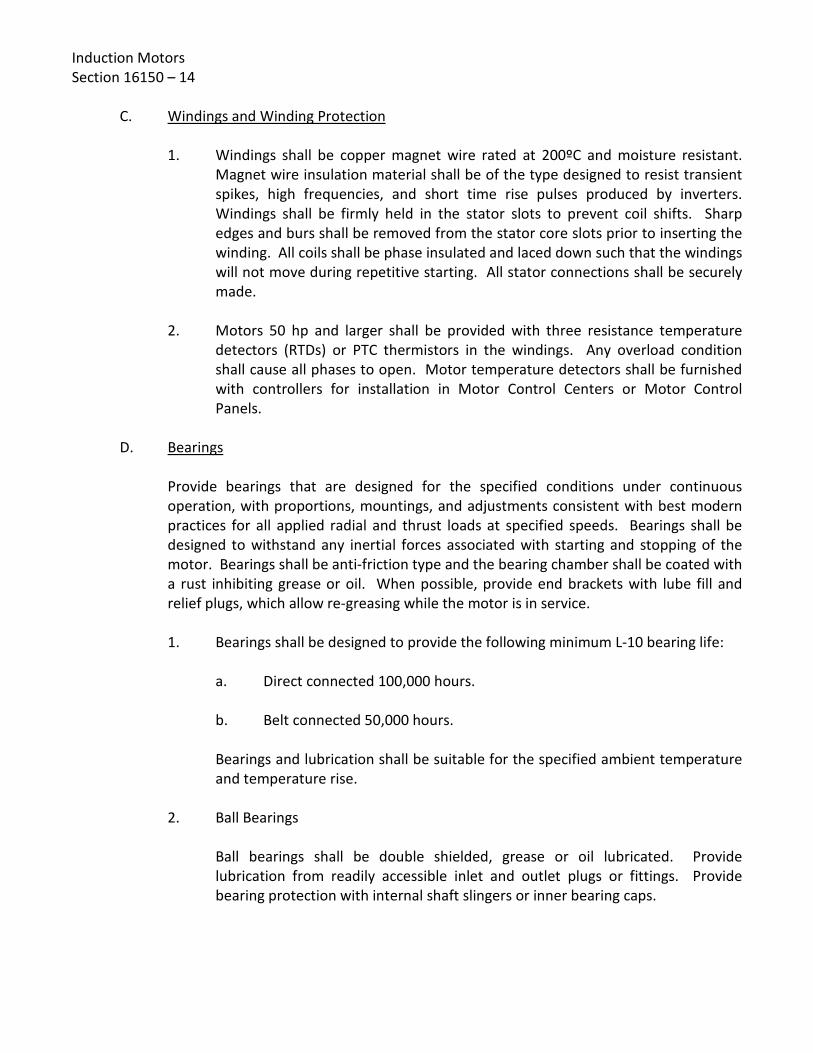
Induction Motors Section 16150 – 14
C. Windings and Winding Protection
1. Windings shall be copper magnet wire rated at 200ºC and moisture resistant. Magnet wire insulation material shall be of the type designed to resist transient spikes, high frequencies, and short time rise pulses produced by inverters. Windings shall be firmly held in the stator slots to prevent coil shifts. Sharp edges and burs shall be removed from the stator core slots prior to inserting the winding. All coils shall be phase insulated and laced down such that the windings will not move during repetitive starting. All stator connections shall be securely made.
2. Motors 50 hp and larger shall be provided with three resistance temperature
detectors (RTDs) or PTC thermistors in the windings. Any overload condition shall cause all phases to open. Motor temperature detectors shall be furnished with controllers for installation in Motor Control Centers or Motor Control Panels.
D. Bearings
Provide bearings that are designed for the specified conditions under continuous operation, with proportions, mountings, and adjustments consistent with best modern practices for all applied radial and thrust loads at specified speeds. Bearings shall be designed to withstand any inertial forces associated with starting and stopping of the motor. Bearings shall be anti-friction type and the bearing chamber shall be coated with a rust inhibiting grease or oil. When possible, provide end brackets with lube fill and relief plugs, which allow re-greasing while the motor is in service.
1. Bearings shall be designed to provide the following minimum L-10 bearing life:
a. Direct connected 100,000 hours. b. Belt connected 50,000 hours. Bearings and lubrication shall be suitable for the specified ambient temperature and temperature rise.
2. Ball Bearings
Ball bearings shall be double shielded, grease or oil lubricated. Provide lubrication from readily accessible inlet and outlet plugs or fittings. Provide bearing protection with internal shaft slingers or inner bearing caps.

Induction Motors Section 16150 – 15
3. Roller Bearings
Provide roller bearings for V-belt drive applications. 4. Oil Lubricated Bearing Housing
Furnish with adequate reservoir depth to provide space for settling of foreign matter. Provide drain plug accessible from motor exterior, and a visual oil level indicator.
5. Ball Bearing Couplings on Horizontal Motors
Construct to absorb total movement and thermal expansion of motor driven equipment shafts.
6. Sleeve Bearings
Sleeve bearings shall be furnished with proper oil rings. The use of wicks or packings are not acceptable.
7. Couplings for Sleeve Bearing Motors
Provide type to prevent motor rotating thrust surface from contacting sleeve bearing thrust collar.
8. Lubrication Fittings
Except on motors equipped with factory-sealed bearings, provide lubrication fittings with easily accessible grease/oil supply, flush, drain, relief, and extension tubes (where necessary).
E. Motor Shaft Motor shaft shall be 1045 Hot Rolled Steel.
F. Fan Cooled
Motors specified as fan cooled shall be equipped with ventilating fans constructed of non-corroding and non-sparking materials.

Induction Motors Section 16150 – 16 2.04 ACCESSORIES AND OPTIONS
A. Grounding
Lugs shall be provided in all motor terminal boxes for grounding. B. Terminal Boxes
1. Motors shall be equipped with terminal boxes for all conduit and wire connections, as specified and as required.
2. Gaskets shall be provided between each terminal box and motor frame, and
terminal box and cover plate. Terminal boxes shall be attached to the motor frames with high strength zinc plated and chromated steel bolts and cap screws.
3. Terminal boxes for motor main power leads shall be over-sized (meeting or
exceeding volumes provided in IEEE 841), diagonally split, and rotatable in 90º increments. Terminal boxes shall be provided with threaded conduit entrances.
4. A separate terminal box shall be provided for motor space heater power leads
and motor winding temperature sensor wiring. Space heater leads and motor winding temperature sensor wiring shall be terminated on terminal blocks.
5. The internal temperature of motor terminal boxes shall allow use of 75ºC rated
conductors. C. Space Heaters
Space heaters shall be designed to maintain the winding temperature at 5°C above the ambient temperature when the motor is not in use. Unless specified otherwise, space heaters shall be 115 V, 1-phase, 60 Hz, and shall be thermostatically controlled. Unless specified otherwise, space heaters shall be provided on all motors 30 hp and larger to be installed outdoors, and on all motors 50 hp and larger to be installed indoors. Space heaters shall be unaffected by the accumulation of moisture and shall have terminals adequately protected against moisture under severe weather conditions. Space heaters shall be mounted on noncombustible material and shall be capable of operating continuously without thermal damage to the motor or themselves. Space heaters shall have a maximum sheath temperature of 200ºC. Power leads for motor space heaters shall be brought out into a terminal box separate from the motor main power leads terminal box.
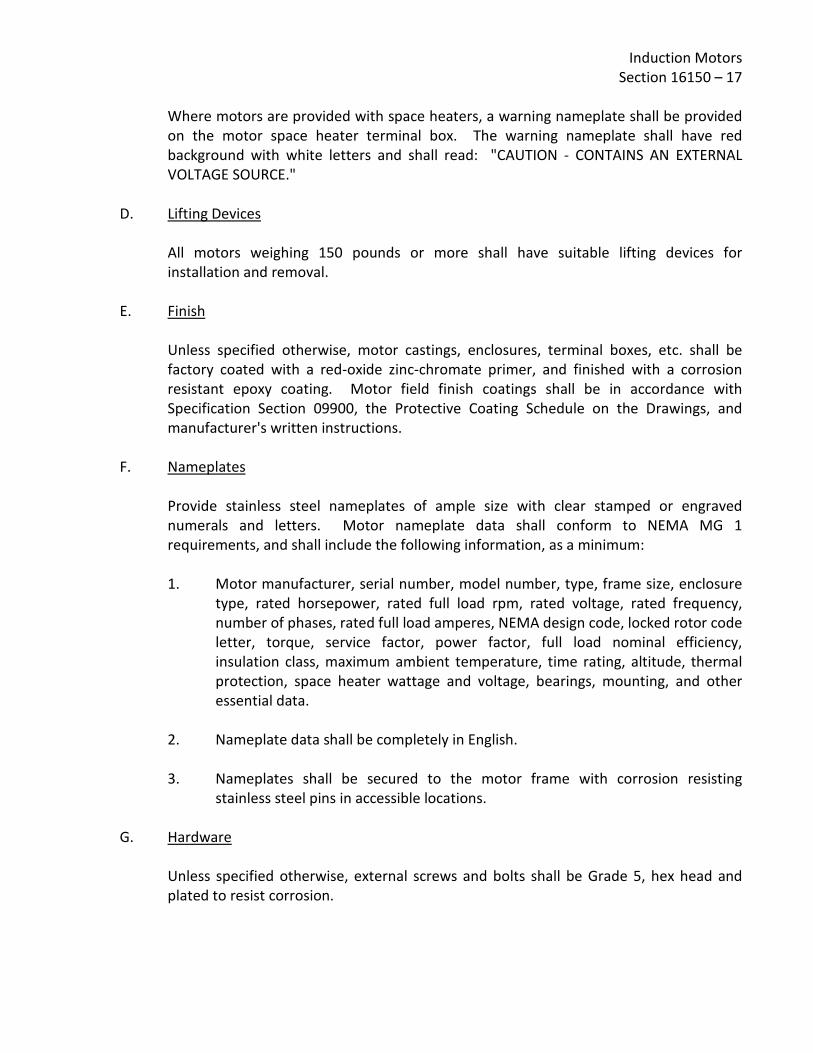
Induction Motors Section 16150 – 17
Where motors are provided with space heaters, a warning nameplate shall be provided on the motor space heater terminal box. The warning nameplate shall have red background with white letters and shall read: "CAUTION - CONTAINS AN EXTERNAL VOLTAGE SOURCE."
D. Lifting Devices
All motors weighing 150 pounds or more shall have suitable lifting devices for installation and removal.
E. Finish
Unless specified otherwise, motor castings, enclosures, terminal boxes, etc. shall be factory coated with a red-oxide zinc-chromate primer, and finished with a corrosion resistant epoxy coating. Motor field finish coatings shall be in accordance with Specification Section 09900, the Protective Coating Schedule on the Drawings, and manufacturer's written instructions.
F. Nameplates
Provide stainless steel nameplates of ample size with clear stamped or engraved numerals and letters. Motor nameplate data shall conform to NEMA MG 1 requirements, and shall include the following information, as a minimum: 1. Motor manufacturer, serial number, model number, type, frame size, enclosure
type, rated horsepower, rated full load rpm, rated voltage, rated frequency, number of phases, rated full load amperes, NEMA design code, locked rotor code letter, torque, service factor, power factor, full load nominal efficiency, insulation class, maximum ambient temperature, time rating, altitude, thermal protection, space heater wattage and voltage, bearings, mounting, and other essential data.
2. Nameplate data shall be completely in English. 3. Nameplates shall be secured to the motor frame with corrosion resisting
stainless steel pins in accessible locations. G. Hardware
Unless specified otherwise, external screws and bolts shall be Grade 5, hex head and plated to resist corrosion.

Induction Motors Section 16150 – 18
H. Dynamic Balance and Vibration
1. All motors shall be dynamically balanced. Methods of measuring dynamic balance shall be in accordance with NEMA MG 1-7.
2. Motors shall have a maximum peak-to-peak amplitude of vibration in
accordance with NEMA MG 1-7.8. PART 3 - EXECUTION 3.01 FACTORY TESTS
A. All Motors Smaller than 100 hp Motors shall be given a standard commercial test.
B. All Motors 100 hp and Larger
Motors shall be given complete tests including: 1. No load running current. 2. Locked rotor current. 3. Full load heat run. 4. High potential test. 5. Winding resistance. 6. Bearing inspection. 7. Locked and idle saturation curves. 8. Service factor heat run. 9. Percent slip. 10. Breakdown torque. 11. Locked rotor torque. 12. Efficiency at full, 3/4, and 1/2 load.

Induction Motors Section 16150 – 19
13. Power factor at full, 3/4, and 1/2 load. 14. Balance to 0.001 inches total amplitude. 15. Noise test. 16. All tests (except locked rotor current) shall be made at full voltage and rated
frequency. 3.02 DELIVERY, STORAGE, AND HANDLING
A. Contractor shall carefully inspect all motors at the time of delivery. Contractor shall notify the District in writing of any damage to the motor or motor components and accessories. Contractor shall repair or replace damaged motors to the satisfaction of the District, all at no additional cost to the District.
B. Storage and handling of motors shall be in accordance with the manufacturer’s written
recommendations. Motors shall not be stored outdoors, and shall be protected from exposure to dirt, fumes, water, corrosive liquids and gases, and physical damage.
C. Contractor shall make provisions to protect motors from moisture by temporary
connection of motor space heaters or installation of temporary heating equipment. Motors shall be protected against condensation until permanent motor power is provided.
D. Motor shafts shall be periodically rotated according to the manufacturer’s instructions.
3.03 INSTALLATION
A. Provide all the equipment installations and wiring installations, including connections as indicated on the Drawings, specified herein, and required.
B. Assure proper fits for all equipment and materials in the spaces shown on the Drawings. C. Coordinate locations of all conduit stub-ups with actual locations of motor terminal
boxes for power and motor auxiliary device connections.
D. General Requirements 1. Motors shall be installed in accordance with requirements of the individual
driven equipment specifications, and in accordance with the manufacturer's recommendations.

Induction Motors Section 16150 – 20
2. Provide the required wiring for motor power, including installation of motor connections in accordance with the motor manufacturer’s requirements.
3. Provide the required wiring for all control equipment that shall be furnished and
installed by other sections of the Specifications. 4. Provide the required wiring for heaters in the motor frames and the required
controls to de-energize the heaters when the motors operate.
E. Install equipment local control stations on steel stanchions and building structures near their respective motors as shown on the Drawings.
F. Provide power, control, alarm, and grounding installations for all motors as indicated on
the Drawings and required. G. Connections of devices sensitive to electromagnetic interferences such as RTDs,
thermistors, thermal protection switches, vibration sensors and other applicable instrumentation wiring shall be provided in accordance with the manufacturer’s written instructions. Shielded conductors shall be provided and routed in dedicated conduits, all in separate conduits runs end to end.
H. Align the motor shaft with driven equipment according to manufacturer’s written
instructions. I. Field damaged factory finish on equipment shall be touched-up with paint that is equal
in quality and color to the original factory finish and in accordance with Specification Section 09900.
3.04 FIELD CHECKS AND TESTS
A. Field Checks 1. Check power and accessory connections for all motors. 2. Confirm correct rotation for all motors. 3. Confirm that the motor and coupled load are properly aligned, rotate freely, and
are not binding. 4. Check all motors for correct clearances and proper installation of all safety
guards and screens. 5. Check all motors for correct lubrication and correct any identified deficiencies in
accordance with the manufacturer’s written instructions.

Induction Motors Section 16150 – 21
B. Field Tests
1. Contractor shall megger (1000 volts, DC) each motor winding before energizing
the motor. If the insulation resistance is found to be low, Contractor shall notify the District and shall not energize the motor. Insulation resistance shall be measured after one (1) minute of megger test run, and all readings shall be recorded.
2. Operating tests shall be performed on the motor driven equipment to observe
that motors start, run, and stop satisfactorily. Contractor shall submit field data to the District. The data shall indicate the full load current for each motor, and current rating for the overload relay in each motor starter and controller.
END OF SECTION 16150

Induction Motors Section 16150 – 22
[PAGE LEFT INTENTIONALLY BLANK]

Revised 09/05/19
SPECIFICATIONS - DETAILED PROVISIONS Section 16160 - Variable Frequency Drives
C O N T E N T S
PART 1 - GENERAL ............................................................................................................................. 1
1.01 SCOPE ........................................................................................................................................ 1 1.02 SPECIFIC PROJECT VFD REQUIREMENTS ................................................................................... 1 1.03 RELATED SECTIONS ................................................................................................................... 1 1.04 REFERENCE STANDARDS, SPECIFICATIONS, AND CODES.......................................................... 2 1.05 SUBMITTALS .............................................................................................................................. 3 1.06 QUALITY ASSURANCE ................................................................................................................ 7 1.07 COORDINATION ........................................................................................................................ 7 1.08 HARMONIC DISTORTION STUDY AND DISTORTION LIMITS ...................................................... 8
PART 2 - PRODUCTS ........................................................................................................................ 10 2.01 DESCRIPTION ........................................................................................................................... 10 2.02 RATINGS .................................................................................................................................. 10 2.03 CONSTRUCTION ...................................................................................................................... 11 2.04 OPERATOR INTERFACE ............................................................................................................ 14 2.05 PROTECTIVE FEATURES ........................................................................................................... 15 2.06 CONTROL INPUTS AND OUTPUTS ........................................................................................... 16 2.07 CONTROL FUNCTIONS AND ADJUSTMENTS ........................................................................... 17 2.08 SERIAL COMMUNICATIONS .................................................................................................... 18 2.09 WIRING AND TERMINATIONS ................................................................................................. 19 2.10 ENCLOSURES, HEATING, AND COOLING ................................................................................. 20 2.11 HARMONIC DISTORTION SUPPRESSION ................................................................................. 21 2.12 MOTOR PROTECTION OUTPUT FILTERS .................................................................................. 26 2.13 EMI/RFI FILTERS ...................................................................................................................... 26 2.14 NAMEPLATES .......................................................................................................................... 26 2.15 SPARE PARTS ........................................................................................................................... 27
PART 3 - EXECUTION ....................................................................................................................... 27 3.01 INSTALLATION ......................................................................................................................... 27 3.02 TESTING AND STARTUP ........................................................................................................... 28 3.03 INSTRUCTION .......................................................................................................................... 29


Variable Frequency Drives Section 16160 – 1
SECTION 16160
VARIABLE FREQUENCY DRIVES PART 1 - GENERAL 1.01 SCOPE
A. This section specifies the requirements for the design, integration, fabrication, assembly, wiring, testing, delivery, and installation of low voltage (600 volt) variable frequency drive (VFD) units to control the speed of electric motor drivers for the driven equipment specified.
B. Contractor shall furnish and install VFDs as specified herein and shown on the Drawings,
including all accessories and controls necessary for a complete and operable system. C. All equipment specified herein shall be furnished as a complete assembly.
1.02 SPECIFIC PROJECT VFD REQUIREMENTS
Specific project requirements may be provided in Section 16160.1 attached to this Specification Section. Where provided, this section provides specific project details regarding VFDs and shall take precedence over requirements herein, in case of conflict.
1.03 RELATED SECTIONS
A. The Contract Documents are a single integrated document, and as such all Specification Sections apply. It is the responsibility of the Contractor and its subcontractors to review all sections and ensure a complete and coordinated project.
B. Related Specification Sections include, but are not limited to, the following:
1. Sections of the Specifications specifying equipment and/or systems requiring electrical power and control.
2. Division 16 – Electrical
3. Division 17 – Instrumentation and Controls

Variable Frequency Drives Section 16160 – 2 1.04 REFERENCE STANDARDS, SPECIFICATIONS, AND CODES
A. Equipment and materials shall meet or exceed the applicable requirements of the following standards, specifications, and codes (latest edition):
Institute of Electrical and Electronics Engineers (IEEE) IEEE 519 Recommended Practice and Requirements for Harmonic Control in
Electric Power Systems IEEE C62.41.1 Guide on the Surge Environment in Low-Voltage (1000 V and Less)
AC Power Circuits IEEE C62.41.2 Recommended Practice on Characterization of Surges in Low-
Voltage (1000 V and Less) AC Power Circuits National Electrical Manufacturers Association (NEMA)
NEMA 250 Enclosures for Electrical Equipment (1000 Volts Maximum) NEMA AB 1 Molded Case Circuit Breakers and Molded Case Switches NEMA ICS 1 Standard for Industrial Control and Systems: General Requirements NEMA ICS 4 Terminal Blocks NEMA ICS 5 Industrial Control Systems, Control Circuit and Pilot Devices NEMA ICS 6 Enclosures NEMA ICS 7 Adjustable Speed Drives National Fire Protection Association (NFPA)
NFPA 70 National Electrical Code

Variable Frequency Drives Section 16160 – 3
Underwriters Laboratories (UL) UL 50 Standard for Enclosures for Electrical Equipment, Non-
environmental Considerations UL 50E Standard for Enclosures for Electrical Equipment, Environmental
Considerations UL 489 Standard for Molded-Case Circuit Breakers, Molded-Case Switches,
and Circuit-Breaker Enclosures UL 508A Standard for Industrial Control Equipment UL 508C Standard for Power Conversion Equipment UL 1283 Standard for Electromagnetic Interference Filters UL 61800-5-1 Standard for Adjustable Speed Electrical Power Drive Systems – Part
5-1: Safety Requirements – Electrical, Thermal and Energy
B. Equipment shall bear the appropriate labels and markings in accordance with above standards, specifications and codes. Equipment shall be designed, manufactured, and tested in certified International Organization for Standardization (ISO) 9001 facilities.
1.05 SUBMITTALS
All submittals shall be in accordance with the General Conditions and requirements specified herein.
A. Shop Drawings Contractor shall submit complete information, drawings, and technical data for all
equipment and components, including, but not limited to, the following:
1. Complete Bills of Materials for all equipment and components comprising the VFD system.

Variable Frequency Drives Section 16160 – 4
2. Manufacturer’s product literature and specifications for all VFD system equipment and components including, but not limited to, the following: variable frequency drives, input filters and line reactors, output filters, isolation transformers, phase shifting transformers, circuit breakers and fuse information (including time current characteristics), bypass contactors, enclosures, control power transformers, pilot devices, relays, timers, fans, and thermostats. Product literature and specifications shall be marked to clearly identify all applicable information and crossing out all inapplicable information. Sufficient data and detail shall be provided to demonstrate compliance with these specifications.
3. Summary for each type of VFD, listing design capabilities and operating
parameters, including all user selectable features and setpoints. 4. VFD efficiency and VFD unit overall operating efficiency (including power for
harmonic mitigation equipment, and power for equipment cooling) at full rated load and 100 percent speed.
5. Motor manufacturer's guarantee that motor insulation and cooling is suitable for
continuous operation over specified frequency range and VFD output pulse maximum peak voltage, pulse rise time, and pulse rate.
6. Drawings showing enclosure exterior elevation, interior elevation, and plan
views with dimensional information, including, but not limited to: enclosure height and depth, section widths and shipping splits (if applicable), conduit stub-up/connection locations, and anchorage/mounting holes. Exterior elevation view shall show location of all door mounted components, including disconnect handle, operator interface, lights, switches, push buttons, and corresponding nameplates. Interior elevation view shall show general arrangement and identification of all major internal components.
7. Terminal size ranges for all cable connections (line and load sides). 8. Complete single line diagrams indicating all components comprising the VFD
system, including, but not limited to: circuit breakers, motor circuit protectors, fuses, contactors, VFDs, control power transformers, control devices, space heaters, and fans.
9. Control ladder diagrams and interconnection diagrams (point to point wiring
diagrams), including terminal blocks and identification numbers. Interconnection diagrams shall show wiring between VFD and all external field devices, and between VFD and all electrical panels, including (but not limited to) distribution panels, MCCs, PLCs, and RTUs.

Variable Frequency Drives Section 16160 – 5
10. Where the proposed enclosure is not the VFD manufacturer’s standard
enclosure (e.g. NEMA 1 enclosure with a NEMA 3R wrapper, or a Hoffman type enclosure), design calculations shall be provided for the enclosure cooling system addressing all heat producing VFD unit components operating at full rated capacity and with the maximum specified ambient temperature. Where building cooling systems are shown on the Drawings, calculations shall be performed with building cooling system off.
11. Harmonic distortion study per Part 1.08 herein, demonstrating compliance with
specified voltage and current distortion requirements. 12. Results for VFD unit(s) from Short Circuit/Coordination and Arc Flash Hazard
Studies per Specification Section 16040.
13. Design calculations and details for equipment seismic design and restraint. Calculations and anchorage details shall be prepared and stamped by a Registered Professional Civil or Structural Engineer in the State of California. Equipment seismic design and restraint calculations shall be provided for all VFD units. Calculations shall include anchor bolt type, size, locations, and embedment depth. Anchor bolt embedment depth for free standing floor mounted VFD units shall be based on the thickness of the structure floor slab only, and shall not include any portion of the raised concrete housekeeping pad beneath the equipment structures. Calculations shall be performed in accordance with the California Building Code (latest edition) for Occupancy Category IV, Essential Facilities.
14. Manufacturer’s installation instructions, including:
a. Receiving, handling, and storage instructions b. Installation procedures including mounting, conduit and wiring
connections, and terminal torque requirements c. Grounding requirements d. Arc flash protection marking e. Operation of operator handles and unit interlocks f. Checklist before energizing g. Procedure for energizing equipment.
15. Manufacturer's warranty guaranteeing the operation of the VFD unit against failure due to defects for two (2) years from date of project acceptance. During this period, parts and labor shall be supplied at no cost to the District.

Variable Frequency Drives Section 16160 – 6
B. Operation and Maintenance Manuals
Operation and maintenance manuals shall be provided in accordance with the requirements of the General Conditions, and Specification Section 01430. Manuals shall be completely indexed and include step-by-step procedures for the operation and maintenance of the VFD as installed. As a minimum, operation and maintenance manuals shall include: 1. Design capabilities, operating parameters, and recommended ranges. 2. Specification packets on all components in the unit. 3. System schematic diagrams, block diagrams, interconnection diagrams, ladder
diagrams, complete wiring diagrams, and enclosure drawings. 4. Safety provisions and precautions, including protective equipment and clothing. 5. Pre-energizing and energizing procedures. 6. Maintenance procedures, including: preventive measures, inspection and
cleaning, servicing, and testing. 7. Troubleshooting. 8. Complete replacement parts list, and list of recommended spare parts. 9. Manufacturer warranties. 10. Contact Information, including name, address, and telephone number of
manufacturer and manufacturer’s local service representative. 11. Complete listing of VFD control settings and setpoints for all controller inputs. Contractor shall provide approved operations and maintenance manuals to District at least 30 days prior to VFD startup and testing.
Final operation and maintenance manuals shall include as-built drawings of all VFD schematic diagrams, block diagrams, interconnection diagrams, ladder diagrams, and enclosure drawings. As-built drawings shall include any field modifications. Final operation and maintenance manuals shall include the complete listing of VFD control settings and setpoints for all controller inputs (factory set and field set) as established at the completion of field startup and testing.

Variable Frequency Drives Section 16160 – 7
1.06 QUALITY ASSURANCE
A. Contractor shall provide a complete, reliable, fully tested, adjustable speed drive system suitable for manned or unmanned operation. VFD units shall be as manufactured by Toshiba, ABB, Allen Bradley, or Schneider Electric (no substitutes).
Third party distributor or packager modifications to a standard product will only be permitted with written approval from the VFD manufacturer, and statement confirming that the installed VFD equipment will be fully covered by manufacturer's warranty. In addition, VFD manufacturer (factory) shall review and approve all shop drawings prepared by third party distributors prior to submittal of said shop drawings to the District.
B. The District believes that the manufacturers listed herein are capable of producing
equipment and/or products that will satisfy the requirements of these specifications. The listing of specific manufacturers herein does not imply acceptance of their products that do not meet the specified ratings, features, functions, and space restrictions. Manufacturers listed herein are not relieved from meeting these specifications in their entirety; and, if necessary, they shall provide non-standard, custom equipment and/or products. Contractor shall be responsible for confirming that the proposed equipment and/or products will meet these specifications.
C. Model numbers supplied herein are provided for information purposes only, to assist
Contractor in selecting equipment that conforms to the Specification and Drawing requirements. In case of any conflict between model numbers provided and the descriptive requirements specified herein, the descriptive requirements shall govern.
1.07 COORDINATION
A. Each VFD unit shall be coordinated with the requirements of the driven equipment. Contractor shall be responsible for matching the motor and the VFD. Load requirements, torque, horsepower, and speed range of VFDs shall be coordinated with and meet or exceed that of the driven equipment.
B. In addition, Contractor shall be responsible for coordinating the collection of data and
manufacturer’s design efforts necessary to comply with all requirements specified herein, including harmonic distortion limits. Contractor shall submit written confirmation to the District that all specified requirements have been satisfied and the proposed VFD has been approved by the driven equipment manufacturer.

Variable Frequency Drives Section 16160 – 8
C. Contractor shall coordinate the working space allowed with the equipment to be provided, and any discrepancies shall be brought to the District's attention prior to the bid opening. Contractor shall be responsible for making the VFD manufacturer and supplier aware of project space requirements and ensuring that the proposed equipment will fit within the allowed space.
D. Where indicated on the Drawings, emergency standby power generation equipment
shall be provided to operate electrical facilities in the event that normal utility power is not available. The VFD system shall be suitable to operate on a limited power generation source. Contractor shall coordinate the design and fabrication of the VFD system equipment and components with emergency power generation equipment, and ensure compatibility and performance in accordance with this Specification.
1.08 HARMONIC DISTORTION STUDY AND DISTORTION LIMITS
A. Harmonic Distortion Study
1. VFD manufacturer shall prepare a comprehensive pre-equipment selection harmonic distortion study of the system. The study shall conform to the requirements of IEEE 519, except as modified herein. The study shall include harmonics from existing equipment as well as the harmonics from equipment provided under this Section. In addition, the study shall include the electrical utility service connection, main service switchboard, distribution switchboards, motor control centers (MCCs), and all interconnecting power cables and busing. The harmonic distortion study shall demonstrate compliance with the harmonic distortion limits specified herein. The harmonic distortion study shall be submitted to the District as part of the shop drawing submittals.
2. VFDs will be provided with electrical power from a Southern California Edison
Company (SCE) transformer and service. The SCE service will provide power to the service switchboard, distribution switchboards (if any), MCCs, and VFDs. Unless specified otherwise, the service switchboard shall be the point of common coupling (PCC) for calculating and measuring voltage and current distortion. Unless specified otherwise, the value of the utility short circuit current at the PCC shall be obtained from SCE by the Contractor for the project location and equipment. Contractor shall be responsible for all necessary coordination with SCE to obtain the short circuit current value, and pay all associated costs for same.

Variable Frequency Drives Section 16160 – 9
3. The harmonic distortion study shall be based on a computer aided system circuit
simulation of the total actual system performed through the 50th harmonic, with information and data obtained from the utility (SCE), Construction Drawings, and equipment manufacturers. Unless indicated otherwise in the Specific Project VFD Requirements, the harmonic analyses shall be performed without any linear loads. The harmonic distortion study shall clearly describe all assumptions, computer input information, voltage and current distortion results, and comparison of results to specified limits.
4. If the harmonic distortion study indicates the need for harmonic suppression
equipment, including: line reactors, passive filters, isolation transformers, 12-pulse VFDs, or 18-pulse VFDs, these shall be provided at no additional cost to the District. Harmonic suppression utilizing active front end VFDs are acceptable. Shop drawings shall indicate the location of the harmonic suppression equipment. Harmonic suppression equipment and its location shall be subject to acceptance by the District, prior to commencing fabrication of the VFDs and associated harmonic suppression equipment.
B. Harmonic Distortion Limits The harmonic distortion values resulting from the operation of all or any combination of
VFDs operating at full load and without any linear loads shall be limited to the following:
1. Maximum allowable Total Harmonic Voltage Distortion, THD Voltage shall be 8%. 2. Maximum allowable individual frequency harmonic voltage distortion shall be
5%. 3. Maximum allowable individual frequency harmonic current distortion; Total
Harmonic Current Distortion, THD Current; and Total Demand Distortion, TDD shall be within the limits of IEEE 519.
Compliance with the specified limits shall be verified by onsite field measurements of the harmonic distortion at the PCC, performed with and without VFDs operating. Field measurements shall be obtained by an independent third party testing firm acceptable to the District, after satisfactory full-load operation of the equipment.

Variable Frequency Drives Section 16160 – 10 PART 2 - PRODUCTS 2.01 DESCRIPTION
A. The VFD shall be solid state with a pulse width modulated (PWM) AC to AC converter utilizing the latest isolated gate bipolar transistor (IGBT) technology. The VFD shall employ a sensorless vector inner loop torque control strategy that mathematically determines motor torque and flux. The VFD shall also provide an optional motor control operational mode for scalar of V/Hz operation.
B. The VFD shall employ a full wave rectifier to prevent input line notching and operate at
a fundamental (displacement) input power factor of 0.98 at all speeds and nominal load. C. Unless specified otherwise, each VFD unit shall include, but not be limited to, the
following major components: solid state VFD (6, 12, or 18-pulse), input line power molded case circuit breaker or motor circuit protector, input current-limiting fuses, line reactor, passive filter (if necessary), motor protection output filter (if necessary), EMI/RFI filter (if necessary), enclosure with door mounted operator interface and pilot devices, control power transformer, integrated controls, enclosure cooling fans, and enclosure space heater.
2.02 RATINGS
A. VFD units shall be sized based on the maximum motor horsepower and required starting and operating torque of the selected equipment to be driven, or the minimum output as shown on the Drawings or specified herein, whichever is greater.
B. VFD units shall be rated to operate from 3-phase power at 480 VAC ±10%. C. VFD units shall be rated to operate continuously at full load under any combination of
the following environmental conditions:
1. Ambient temperature of 0 to 40°C; and where specified, up to 50°C with application of a derating factor. VFD units that can operate at 40°C intermittently (during a 24 hour period) are not acceptable and shall be sized (i.e. oversized) to operate continuously at the specified maximum ambient temperature.
2. Altitudes ranging from 0 to 3300 feet above sea level without derating. 3. Relative humidity of 95% or less (non-condensing).
D. VFD output frequency shall be adjustable between 0 Hz and 300 Hz (minimum).

Variable Frequency Drives Section 16160 – 11
E. VFDs shall be rated to operate from input power ranging from 48 Hz to 63 Hz. F. Output voltage and current ratings shall match the adjustable frequency operating
requirements of standard NEMA Design B motors. G. Unless specified otherwise, VFDs shall have an overload current capacity for a duration
of one (1) minute of at least 110% of rated motor current for variable torque units and at least 150% of rated motor current for constant torque units.
H. VFD efficiency shall be 98% or better at the full rated capability of the VFD at full speed
and load. VFD unit overall efficiency, including all harmonic mitigation equipment, output reactor, sine wave filter, dV/dt filters, cooling fans, control power transformers, etc. shall be 95% or better of the full rated capability of the VFD at full speed and load.
I. VFDs shall be protected from atmospheric contamination by chemical and solid
substances per IEC 60721-3-3. Chemical substances shall be classified 3C2 and solid substances shall be classified 3S2.
2.03 CONSTRUCTION
A. All VFD microprocessor and control circuitry shall be isolated by rigid non-conductive barriers providing finger-safe protection from all AC and DC power circuitry.
B. All power semiconductors shall be accessible from the front of the unit without the
removal of the heat sinks upon which the devices are mounted. Each power semiconductor shall be capable of being visually inspected, electrically checked, and mechanically replaced from its heat sink assembly without removal of the entire heat sink or heat sink covers.
C. Each VFD unit shall be provided with an input molded case circuit breaker or motor
circuit protector with a short circuit interrupting capacity of 65,000 RMS symmetrical amps (minimum), which shall disconnect all line power to the VFD, bypass contactors (if applicable), harmonic distortion suppression equipment, and control power transformer. The input power disconnect shall be provided with a door mounted operator that is padlockable in the Off position and mechanically interlocked with the VFD unit enclosure door.
D. Each VFD unit shall be provided with input line power fuses. Fuses shall be current
limiting type with a short circuit interrupting rating of 200,000 amps, and shall be provided with blown fuse indicators.

Variable Frequency Drives Section 16160 – 12
E. Each VFD unit shall be provided with a 480V/120V control power transformer equipped with primary and secondary fuses. Unless indicated otherwise on the Drawings, the control power transformer shall be sized all control power loads, and enclosure cooling and heating loads.
F. Each VFD unit shall be equipped to function as specified herein and as indicated on the
Drawings.
G. Door Mounted Components and Pilot Devices
Unless indicated otherwise on the Drawings, each VFD unit shall be provided with the following door mounted components and pilot devices.
1. Padlockable handle for VFD unit circuit breaker. 2. Power on indicator with push to test LED lamp. 3. VFD on-line indicator with push to test LED. 4. Bypass on-line indicator lamp (if bypass contactors are specified). 5. VFD malfunction indicator with push to test LED lamp. 6. VFD fault reset push button. 7. Motor thermal and motor overload reset push buttons. 8. Operator Interface (Digital Display/Keypad Unit). Unit shall control, monitor and
display VFD functions, operating conditions and faults. Operating conditions shall include, but not be limited to: output frequency, output voltage, motor current, running speed (rpm), input and output power.
9. VFD Manual, VFD Auto, Off, Bypass Manual (if bypass contactors are specified)
selector switch as specified. Selector switch shall be provided with auxiliary contacts for position signal to remote control panel.
10. Elapsed time meter (eight (8) digit, minimum). 11. Motor high temperature indicator lamp. 12. Motor overload indicator lamp. 13. Speed pot for VFD speed control in Hand mode.

Variable Frequency Drives Section 16160 – 13
14. Other functions and devices shown on the Drawings, or otherwise specified.
VFD shall shutdown on motor "high temperature" and "overload" conditions. External
dry contacts shall be provided for each motor alarm condition and common VFD fault condition.
VFD unit pilot devices shall be in accordance with Specification Section 16480.
H. VFD Bypass
Where indicated on the Drawings or specified in the Specific Project VFD Requirements, VFD units shall be provided with bypass contactors to permit the motor to run at full speed in the event of a VFD shutdown. Unless specified otherwise, the VFD bypass shall be provided with the following components and features:
1. The bypass circuitry shall be located in a separate section of the VFD unit
enclosure and shall isolate the VFD on both the line side and load side. For motors less than 100 hp, VFD units shall be provided with mechanically and electrically interlocked full-voltage bypass contactors sized for the motor full load amperage. For motors 100 hp and greater, VFD units shall be provided with solid-state reduced voltage starting (soft starter) for bypass motor starting; and the soft start shall be electrically interlocked with the VFD isolation contactors. Controls shall be provided for automatic bypass of the VFD to constant speed operation in event of VFD failure, except for condition of motor high temperature, motor overload, or motor moisture. When selector switch is in VFD Auto position, upon VFD failure the equipment shall stop and automatically restart in constant speed mode via bypass contactors with start/stop functioning as if operating on VFD. Time delay for restart in bypass mode shall be provided. Manual reset to return to VFD mode shall be required. The VFD shall be isolated on the line-side and load-side during bypass operation. The bypass motor starter shall be equipped with current overload protection and a minimum of one (1) NO and one (1) NC auxiliary contactors.
2. Full voltage contactors and soft starters shall be provided in accordance with
Section 16480.
3. Indicating lights for operation in VFD mode and Bypass mode shall be provided. Selector switch shall be provided with Bypass Manual position to allow operation in bypass mode without VFD failure.
4. Dry contacts shall be provided for operation in bypass mode for connection to
RTU and/or Plant SCADA system.
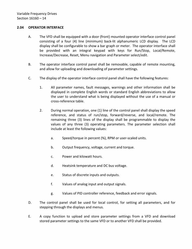
Variable Frequency Drives Section 16160 – 14 2.04 OPERATOR INTERFACE
A. The VFD shall be equipped with a door (front) mounted operator interface control panel consisting of a four (4) line (minimum) back-lit alphanumeric LCD display. The LCD display shall be configurable to show a bar graph or meter. The operator interface shall be provided with an integral keypad with keys for Run/Stop, Local/Remote, Increase/Decrease, Reset, Menu navigation and Parameter select/edit.
B. The operator interface control panel shall be removable, capable of remote mounting,
and allow for uploading and downloading of parameter settings. C. The display of the operator interface control panel shall have the following features:
1. All parameter names, fault messages, warnings and other information shall be displayed in complete English words or standard English abbreviations to allow the user to understand what is being displayed without the use of a manual or cross-reference table.
2. During normal operation, one (1) line of the control panel shall display the speed
reference, and status of run/stop, forward/reverse, and local/remote. The remaining three (3) lines of the display shall be programmable to display the values of any three (3) operating parameters. The parameter selection shall include at least the following values:
a. Speed/torque in percent (%), RPM or user-scaled units. b. Output frequency, voltage, current and torque. c. Power and kilowatt hours. d. Heatsink temperature and DC bus voltage. e. Status of discrete inputs and outputs. f. Values of analog input and output signals. g. Values of PID controller reference, feedback and error signals.
D. The control panel shall be used for local control, for setting all parameters, and for stepping through the displays and menus.
E. A copy function to upload and store parameter settings from a VFD and download
stored parameter settings to the same VFD or to another VFD shall be provided.

Variable Frequency Drives Section 16160 – 15
2.05 PROTECTIVE FEATURES
The VFD unit shall be provided with capabilities and features to protect the VFD components and the driven motor from damage. Protective features with user adjustable setpoints shall be accessed through the operator interface for enabling and disabling. As a minimum, each VFD unit shall be provided with the following protective features:
A. A message shall be displayed on the operator interface for each programmed warning
and fault protection function. The VFD shall be capable of displaying up to five (5) active faults and store the previous five (5) non-active faults and provide a time stamp of when the faults occurred. The VFD shall provide a help feature to further explain the displayed fault.
B. The VFD shall be provided with internal metal-oxide varistors (MOVs) for phase-to-
phase and phase-to-ground line voltage transient protection. C. Output short circuit and ground fault protection rated for 100,000 amps (without relying
on line fuses) shall be provided per UL508A. D. Motor phase loss protection shall be provided. E. The VFD shall provide electronic motor overload protection qualified per UL508C. F. Protection shall be provided for AC line or DC bus overvoltage at 130% of maximum
rated voltage or undervoltage at 65% of minimum rated voltage. G. The VFD shall be provided with protection against input phase loss. H. Stall protection shall be programmable to provide a warning or stop the VFD after the
motor has operated above a programmed torque level for a programmed time limit. I. Underload protection shall be programmable to provide a warning or stop the VFD after
the motor has operated below a selected underload curve for a programmed time limit. J. Over-temperature protection shall provide a warning if the power module temperature
is less than 5°C below the over-temperature trip level. K. Desaturation circuit to drive the inverter section transistor base current to zero in the
event of a controller fault. L. Input terminals shall be provided for connecting a motor winding thermistor (PTC type)
to the VFD’s protective monitoring circuitry. An input shall also be programmable to monitor an external motor high temperature relay or switch contact.

Variable Frequency Drives Section 16160 – 16 2.06 CONTROL INPUTS AND OUTPUTS
A. Discrete Inputs
1. Minimum of six (6) discrete inputs shall be provided. 2. The inputs shall be independently programmable with function selections
(run/stop, hand-off-auto, etc.). 3. Inputs shall be designed for use with either the VFD’s internal 24 VDC supply or a
customer supplied external 24 VDC supply.
B. Discrete Outputs
1. Minimum of two (2) form C relay contact outputs shall be provided. 2. All outputs shall be independently programmable to activate with at least
30 function selections including:
a. Operating conditions such as drive ready, drive running, reversed, and at set speed.
b. General warning and fault conditions. c. Adjustable supervision limit indications based on programmed values of
operating speed, speed reference, current, torque, and PID feedback. d. Relay contacts shall be rated to switch 2 A at 24 VDC or 115/230 VAC.
C. Analog Inputs
1. Minimum of two (2) analog inputs shall be provided and shall be selectable for either a current or a voltage input.
2. Inputs shall be independently programmable to provide signals including speed/frequency reference, torque reference or set point, PID set point and PID feedback/actual.
3. A differential input isolation amplifier shall be provided for each input. 4. Analog input signal processing functions shall include scaling adjustments,
adjustable filtering and signal inversion.

Variable Frequency Drives Section 16160 – 17
5. If the input reference is lost, the VFD shall give the user the option of the
following:
a. Stopping and displaying a fault. b. Running at a programmable preset speed. c. Holding the VFD speed based on the last good reference received. d. Cause a warning to be issued, as selected by the user. The VFD shall be programmable to signal the lost input reference condition via an operator interface warning, relay output, and/or over the serial communications bus.
D. Analog Outputs
1. Minimum of two (2) 4-20 mA analog outputs shall be provided. 2. Outputs shall be independently programmable to provide signals proportional to
output function selections including output speed, frequency, voltage, current, and power.
2.07 CONTROL FUNCTIONS AND ADJUSTMENTS
A. Output frequency shall be adjustable between 0 Hz and 300 Hz (minimum). Operation above motor nameplate speed shall require programming changes to prevent inadvertent high-speed operation.
B. Stop mode selections shall include coast to stop and ramp to stop. C. The VFD shall be capable of controlling deceleration of a load without generating an
overvoltage fault caused by excessive regenerated energy. Overvoltage control on deceleration shall extend the ramp time beyond the programmed value to keep the amount of regenerated energy below the point that causes overvoltage trip.
D. The VFD shall be capable of controlling a rotating motor regardless of the motor
direction. From the time the start signal is given to the VFD to the time the VFD has control of the motor shall not exceed two (2) seconds. Once the VFD has control of the motor it shall then accelerate or decelerate the motor to the active reference speed without tripping or faulting or causing component damage to the VFD. The VFD shall also be capable of flux braking at start to stop a reverse spinning motor prior to ramp.

Variable Frequency Drives Section 16160 – 18
E. The VFD shall have the ability to automatically restart after a protective trip caused by overcurrent, overvoltage, undervoltage, or loss of input signal. The number of restart attempts, trial time, and time between reset attempts shall be programmable.
F. Control functions shall include two (2) sets of acceleration and deceleration ramp time
adjustments with linear and an s-curve ramp time selection. G. Speed control functions shall include:
1. Adjustable minimum and maximum speed limits. 2. Selection of up to 15 preset speed settings for external speed control. 3. Three sets of critical speed lockout adjustments. 4. A built-in PID controller to control a process variable such as pressure, flow or
fluid level.
H. Functions shall include motor flux optimization for optimizing energy efficiency and limit the audible noise produced by the motor by providing the optimum magnetic flux for any given speed / load operating point.
I. The VFD shall be capable of sensing a loss of load (e.g. broken belt or broken coupling)
and signal the loss of load condition. The VFD shall be programmable to signal this condition via an operator interface warning, relay output, and/or over the serial communications bus. Relay output shall include programmable time delays that shall allow for VFD acceleration from zero speed without signaling a false underload condition.
J. A minimum of two (2) programmable critical frequency lockout ranges shall be provided
to prevent the VFD from operating the load continuously at an unstable or critical equipment speed.
2.08 SERIAL COMMUNICATIONS
A. The VFD shall be capable of communicating with other VFDs or controllers via a serial communications link. A variety of communications interface modules for the typical overriding control systems shall be available.
B. Interface modules shall be available for a number of communication protocols including,
but not limited to: Modbus RTU and ModBus TCP. C. Interface modules shall mount directly to the VFD control board or be connected via
fiber optic cables to minimize interference and provide maximum throughput.

Variable Frequency Drives Section 16160 – 19
D. VFD I/O shall be accessible through the serial communications adapter. Serial
communication capabilities shall include, but not be limited to:
1. Run-Stop control. 2. Hand-Off-Auto control. 3. Speed adjustment. 4. PID (proportional/integral/derivative) control adjustments. 5. Current limit control. 6. Acceleration and deceleration time adjustments.
E. The VFD shall have the capability of allowing the overriding controller to monitor feedback such as process variable feedback, output speed/frequency, current (in amps), % torque, power (kW), kilowatt hours (resettable), operating hours (resettable), relay outputs, and diagnostic warning and fault information.
F. A connection shall also be provided for a personal computer interface. Personal
computer software shall be provided for VFD setup, diagnostic analysis, monitoring and control. The software shall provide real time graphical displays of VFD performance.
2.09 WIRING AND TERMINATIONS
A. As a minimum, interconnecting wiring and wiring to terminals for external connection shall be stranded copper with thermoplastic insulation that is moisture-resistant and flame-retardant, and rated at 600 V and 90°C.
B. Where fine stranded conductors, Class C and higher (such as DLO cable) are utilized for
internal wiring, all terminations in mechanical lugs shall be provided with copper flex-cable compression adapters to properly confine the fine strands and prevent overheating of the connection and wire pullout from lugs. The flex-cable compression adapters shall fit mechanical set-screw mechanical lug type connectors and shall be sized for the full current carrying capacity of the cable. The adapters shall be provided a flared barrel-opening to allow easy cable insertion. The adapter shall be constructed of wrought copper with pin of Class B stranded copper conductor, rated for 600 V and 105ºC cable, and shall be UL listed. Pin length shall be sufficient to allow full engagement into the mechanical lug. Flex-cable copper compression adapters shall be Shoo-pin PT-FX Series, as manufactured by Greaves Corporation, or equal.
C. Wiring shall be neatly installed in wireways wherever possible, or bundled with wire tie-
down straps and securely attached to mounting surfaces.

Variable Frequency Drives Section 16160 – 20
D. Terminals on door mounted components shall be provided with finger-safe protective barriers; or alternatively, a single clear plastic protective barrier shall be provided covering all terminals.
E. Terminal blocks shall be interlocking, track-mounted type, with a marking strip, covers,
and pressure connectors. A terminal shall be provided for each conductor of external circuits, plus one ground for each shielded cable. Each control loop shall be individually fused and located for ease of maintenance.
F. Terminals shall be labeled to match with the identification shown on the shop drawings.
2.10 ENCLOSURES, HEATING, AND COOLING
A. VFD units shall be housed in wall mounted or floor mounted enclosures as shown on the Drawings and specified herein. Enclosures shall be of sufficient size to afford access to all parts and components, and constructed with all line, load, and control terminations fully front accessible. All control components and wiring shall be separated by rigid non-conductive barriers from all 3-phase AC and DC power components and wiring.
B. Where shown on Drawings or specified herein that the VFD shall be installed in a MCC
line-up, the enclosure shall match MCC construction including height and depth.
C. Unless otherwise specified, the sheet metal surfaces of all enclosures shall be phosphetized and coated with a rust resisting primer. Over the primer a corrosion resistant baked enamel finish shall be applied on interior and exterior metal surfaces. Exterior color shall be medium light gray (unless otherwise specified) and interior color shall be white. All enclosure hardware shall have a corrosion resistant finish.
D. Unless otherwise specified, outdoor electrical equipment shall be housed in weatherproof, gasketed, NEMA Type 1 (dead front with front accessibility) enclosures with NEMA 3R wrappers, and indoor electrical equipment shall be housed in NEMA Type 12 (dead front with front accessibility) enclosures or gasketed NEMA Type 1 enclosures. Enclosures shall be provided with top and bottom entry/exit locations for conduit and power/control conductors.
E. Outdoor enclosures shall be provided with padlockable door handles and sufficient
internal lighting to perform maintenance work. Lighting shall be controlled by an internal light switch. Unless otherwise specified, lighting shall be powered by the VFD control power transformer.

Variable Frequency Drives Section 16160 – 21
F. Enclosures shall be provided with 120 V, 60 Hz space heaters for condensation
protection. Space heaters shall be strip or tubular type and shall be controlled by line voltage thermostats. Unless otherwise specified, heating systems shall be powered by the VFD control power transformer.
G. Where specified environmental conditions necessitate enclosures to be ventilated
and/or provided with forced air cooling, all enclosures be gasketed and be equipped with gasketed air filters to prevent entry of dust. All cooling fans shall be constructed to enable regular maintenance or removal without dismantling of the VFD unit. Air filters shall be washable aluminum mesh type and shall be removable (without the use of tools) for cleaning. Refer to environmental conditions as specified herein and requirement to submit cooling calculations.
H. Where indicated on the Drawings or where specified environmental conditions
necessitate VFDs to be provided with mechanical cooling, outdoor enclosures shall be gasketed NEMA Type 1 with walk-in gasketed NEMA Type 3R wrappers. The walk-in space between the NEMA Type 1 doors and NEMA Type 3R doors shall be air-conditioned with a pad mounted commercial air conditioner located adjacent to the enclosure. Supply and return ducting between the air conditioner and enclosure shall be insulated and weatherproofed. The air conditioner location shall be subject to the District’s review and approval.
2.11 HARMONIC DISTORTION SUPPRESSION
The electrical system shall be provided with the necessary equipment to protect the VFDs and power system(s) on the line side of the VFDs from harmonic distortion, as specified in Part 1.08 herein. Prior to equipment selection, a harmonic distortion study shall be performed to determine the characteristics and ratings of individual line reactors, passive filters, isolation transformers, 12-pulse VFDs, 18-pulse VFDs, or other suppression equipment necessary to achieve the specified distortion limits. Unless indicated otherwise in the Specific Project VFD Requirements, active filters or active front end VFDs will not be allowed for suppression of harmonic distortion.
A. Line Reactors
1. Unless otherwise specified, each VFD shall be provided with a line reactor. The line reactor shall be factory mounted and wired within the VFD unit enclosure.

Variable Frequency Drives Section 16160 – 22
2. Line reactors shall be provided on the incoming power lines to the VFDs to:
a. Minimize the effects of "line notching" due to the switching of power semiconductor devices for controlled rectifier type drives.
b. Prevent overvoltage trips and/or damage to the drive itself due to
transients (i.e. utility power capacitor switching, etc.) on the VFD incoming power lines.
c. Reduce input harmonic currents thereby improving the total power
factor of the drive system.
3. The line reactor shall provide a minimum of 3% line impedance and be designed for harmonic filtering service and for slowing the rate of rapid current changes.
4. Line reactors shall be in accordance with the requirements specified herein, and
shall be as manufactured by Trans-Coil, Inc., MTE Corp., or equal.
B. Passive Filters
1. Passive filters, if selected for harmonic distortion suppression, shall be provided for each VFD unit. Passive filters shall be factory mounted and wired within the VFD unit enclosure.
2. Passive filters shall contain tuned circuits designed to remove harmonics
generated within the power distribution system while improving the system power factor. Passive filters shall consist of inductive and capacitive elements configured and tuned to resonate just below the harmonic frequency for which they are designed to filter.
3. Passive filters shall be provided with 3-phase contactors, which shall disengage
the filter capacitor cells when the VFD is not running and engage the filter capacitor cells when the VFD is running. As a minimum, provide an adjustable (0 to 30 second) time-delay relay, which shall energize via a run contact from the VFD and cause the capacitor cell contactors to engage at the end of the time delay. Manufacturer shall modify the control diagrams shown on the Drawings as required to perform the above function.
4. Passive filters shall be in accordance with the requirements specified herein, and
shall be as manufactured by Trans-Coil, Inc., MTE Corp., or equal.

Variable Frequency Drives Section 16160 – 23
C. Components for Line Reactors and Passive Filters
Line reactor and passive filter components shall comply with the following minimum requirements:
1. Inductors
a. Both series line reactors and tuning reactors (inductors) shall be designed for harmonic filtering service and for slowing the rate of rapid current changes. The inductors shall be UL component-recognized and shall be built to comply with UL 508. Construction shall be of copper wire-wound on magnetic steel cores. Inductors shall be three-phase. Series line reactors shall be sized appropriately for the total connected load. Design maximum temperature rise for inductors shall be 115°C on bobbin wound and 155°C on form wound devices at rated current.
b. The core shall be constructed of laminated, magnetic steel (grade M36 or
better). Brackets shall be ASTM structural steel or structural aluminum. Coils shall be wedged in place and the core shall be locked in place using vertical ties or rods.
c. Windings shall consist of copper wire or of copper foil. Terminations shall
be copper alloy ring lugs, UL-recognized terminal blocks, or solid copper bus. Sheet insulation shall be DuPont Nomex 410, or 3M Cequin of the thickness as required for UL insulation systems.
d. Completed inductors shall be impregnated, using 100% solid epoxy resin.
All insulation varnish systems shall be rated Class H (180°C) or Class R (220°C), 600 V. Inductors shall be Hi-Pot tested (2,500 V, 60 Hz, 1 minute) line-to-line and line-to-ground.
e. Inductors shall be air-gapped to avoid control point saturation.
Inductance shall be measured under full load and shall be within -2% to +8% for the tuning reactor and +/- 20% for the series line reactor, of the design value.

Variable Frequency Drives Section 16160 – 24
2. Capacitor Cells a. Capacitor cells shall have a voltage rating capable of handling
continuously the nominal system voltage plus 10% of the over voltage tolerance. Capacitor cells shall also be capable of operating under the worst case voltage gain due to the leading nature of the capacitive current. Dielectric material shall be low-loss (less than 0.25 watts per kVAR).
b. Capacitor cells shall be standard (non-custom), high-endurance type, and
shall be contained in hermetically sealed metal cans. Capacitor cells shall be rated to operate at an ambient temperature of 65°C.
c. Capacitor cells shall be provided with a UL mandated, pressure-sensitive
interrupter which, in case of a hazardous internal pressure increase, shall disconnect all three phases simultaneously. Capacitor cells shall be recognized or listed under UL810.
d. Individual capacitor cells, or groups of cells, shall be provided with a 3-
phase, discharge resistor network. The resistors shall be sized to reduce residual voltage to less than 50V within one minute of de-energization (per NEC Article 460-6).
e. The RMS current in each capacitor cell at full load shall not exceed 150%
of the current at no load to limit the stress on the capacitors.
3. Contactors
a. Contactors shall be provided in the capacitor cell circuit. Contactors, shall be used in conjunction with the VFDs run relay, and shall remove the capacitors from the circuit when the motor is not operating; thereby, eliminating the opportunity for “leading” power factor condition.
b. Contactors shall be designed for 3-phase capacitor cell switching
applications, and shall be rated for 600 volts and be UL listed.

Variable Frequency Drives Section 16160 – 25
4. Protection
a. Internal wiring, including wiring for the tuning reactors, shall be protected by three fuses, one for each phase. Fuses shall be current limiting type and rated for a minimum interrupting current of 200,000 symmetrical amperes at 600 VAC, 60 Hz.
b. Fuses shall be Class T and shall be UL listed. Fuses shall be sized for a
minimum of 150% of nominal capacitor cell rating. Fuses internal to capacitor cells shall not be acceptable as the primary means of protection.
c. Protective barriers shall be furnished as necessary to provide finger-safe
protection between 3-phase power components and control power circuitry.
5. Connections
a. Unless otherwise specified, compression type, pure copper or copper alloy terminal lugs shall be provided for electrical connections of harmonic filters to 3-phase line power. An internal grounding lug shall also be provided. Lugs shall be UL listed.
b. Distribution blocks, when necessary, shall be rated for copper wire and
shall be UL listed or recognized.
6. Wire
a. Unless specified otherwise, interconnecting wiring for inductors and capacitor cells shall be constructed of copper with thermoplastic insulation that is rated at 600 V and for a minimum of 90°C. All control wiring shall be copper wire that is rated at 600 V and 90°C.
b. Signal wire shall be multi-conductor jacketed wire that is rated at 300 V
and 80°C.

Variable Frequency Drives Section 16160 – 26
7. Enclosures a. Unless specified otherwise, harmonic filters and reactors shall be
incorporated in the VFD unit’s enclosure. Wherever possible, harmonic filters and reactors shall be mounted in a separate section of the enclosure from the VFD assembly.
b. The filters and reactors shall be provided with integral mounting brackets
for horizontal or vertical mounting.
2.12 MOTOR PROTECTION OUTPUT FILTERS
A. Where the conductor length between the VFD and motor exceeds 100 feet, or where specified on the Drawings or in the Specific Project VFD requirements, a motor protection output filter shall be provided within the VFD enclosure. The motor protection output filter shall be a low pass filter which protects the motor and power cables from voltage spiking. The output filter shall be sized for the motor load and shall be located immediately adjacent to the output terminals of the VFD.
B. Motor output filter components shall be in accordance with Part 2.11, C herein. C. The motor protection output filter shall be Model V1k as manufactured by Trans-Coil,
Inc., Model dV Sentry as manufactured by MTE Corp., or equal.
2.13 EMI/RFI FILTERS
A. An electromagnetic interference and radio frequency interference (EMI/RFI) filter shall be provided on the incoming power lines of the VFD if required as a result of system startup and testing to prevent conducted radio frequency noise generated by the VFD from interfering with other sensitive electronic equipment (such as lighting systems, telecommunications equipment, instrumentation, etc.).
B. The EMI/RFI filter shall be capable of handling a 400% current overload at startup and a
150% current overload for at least 1 minute (minimum once per hour) when operating. C. The EMI/RFI filter shall be designed and fabricated to meet the requirements of UL
1283. EMI/RFI filters shall be as manufactured by Schaffner, or equal.
2.14 NAMEPLATES
Nameplates shall be provided bearing the VFD unit description as indicated on the Drawings. In addition, nameplates shall be provided for all door mounted components and devices. Nameplates shall be in accordance with Specification Section 16480, Part 2.05.
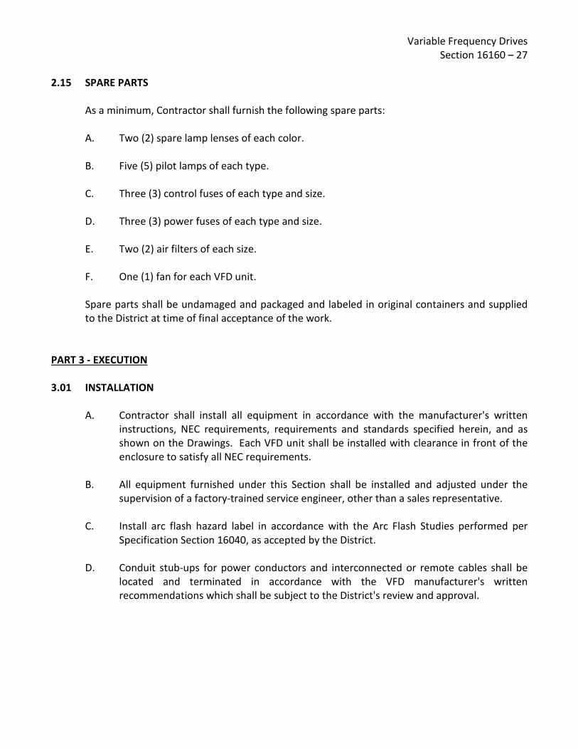
Variable Frequency Drives Section 16160 – 27
2.15 SPARE PARTS
As a minimum, Contractor shall furnish the following spare parts:
A. Two (2) spare lamp lenses of each color. B. Five (5) pilot lamps of each type. C. Three (3) control fuses of each type and size. D. Three (3) power fuses of each type and size. E. Two (2) air filters of each size. F. One (1) fan for each VFD unit.
Spare parts shall be undamaged and packaged and labeled in original containers and supplied to the District at time of final acceptance of the work.
PART 3 - EXECUTION 3.01 INSTALLATION
A. Contractor shall install all equipment in accordance with the manufacturer's written
instructions, NEC requirements, requirements and standards specified herein, and as shown on the Drawings. Each VFD unit shall be installed with clearance in front of the enclosure to satisfy all NEC requirements.
B. All equipment furnished under this Section shall be installed and adjusted under the
supervision of a factory-trained service engineer, other than a sales representative. C. Install arc flash hazard label in accordance with the Arc Flash Studies performed per
Specification Section 16040, as accepted by the District.
D. Conduit stub-ups for power conductors and interconnected or remote cables shall be located and terminated in accordance with the VFD manufacturer's written recommendations which shall be subject to the District's review and approval.
Variable Frequency Drives Section 16160 – 28
E. Contractor shall anchor VFD enclosures to walls or floors in accordance with the calculations and details prepared by the manufacturer's engineer. Floor mounted enclosures shall be mounted on concrete bases, extending 3 inches above the surrounding ground or floor. Anchor bolt embedment depth shall be based on the thickness of the structure slab only, and shall not include any portion of the raised concrete housekeeping pad beneath the equipment.
F. Contractor shall require the VFD manufacturer to examine the Contract Documents as
to the location and operating environment that the VFD unit will be subjected to, and advise the District prior to bidding of any potential problems, which could prevent the VFD from functioning as specified and as intended.
G. Perform all pre-energizing checks as recommended by the VFD manufacturer. Under no
circumstances are any portions of the VFD unit to be energized without written authorization from the manufacturer's representative, as specified below.
3.02 TESTING AND STARTUP
A. Upon completion of manufacturing, each VFD unit shall be factory inspected and load tested. In addition, all VFD unit control logic shall be factory tested by simulating external control signals. Written certification that the factory inspections, load tests, and control logic testing have been successfully performed shall be submitted to the District prior to VFD unit shipment. All costs associated with said factory tests shall be included in the Contractor's bid.
B. Manufacturer or supplier of the equipment furnished under this Section shall furnish the
services of competent factory-trained personnel to provide technical assistance during installation and startup of the VFD equipment.
C. Prior to the commencement of field testing, manufacturer’s service engineer shall
perform the following:
1. Set and/or adjust all operating parameters according to the manufacturer's written instructions and District's preference for VFD features, which may be enabled or disabled through the operator interface.
2. Provide District with a complete listing of all VFD operating parameters (control
settings and setpoints for all controller inputs). 3. Provide District with written certification stating that the VFD equipment,
including controls, have been properly installed and adjusted, and are ready for operation.

Variable Frequency Drives Section 16160 – 29
D. Field Testing
1. VFD field testing shall be conducted concurrently with field testing of the driven
equipment. All field testing shall be witnessed by the District. 2. Field testing shall demonstrate satisfactory operation of all interlocks, alarms,
and normal operational sequences. The VFD manufacturer shall utilize suitable field test equipment to locate and correct all malfunctions. Repeated failure of any component will cause the test to be terminated and restarted when equipment has been repaired or replaced. VFD performance shall be documented by obtaining concurrent readings showing input and output: voltage, amperage, power factor, and power over the full speed range of driven equipment.
3. Harmonic distortion field tests shall be conducted at the PCC (service
switchboard bus, unless otherwise specified) to determine the voltage distortion and current distortion, and compliance with specified limits. Measurements shall be made utilizing a Dranetz HDPQ Xplorer 400 analyzer (or equal) capable of recording current and voltage distortions. Measurements shall include phase-to-phase, phase-to-neutral, and neutral-to-ground. Measurements shall be obtained over the full range of VFD operation, and shall include individual voltage and current harmonic values up to the 50th harmonic as well as total harmonic distortion (THD) and total demand distortion (TDD). Graphs of the test results shall be submitted for speed values of 60%, 80%, and 100%. Also, testing shall be performed with no VFD units operating, then one unit, then two units, then three units, etc. operating simultaneously (no concurrent linear loads).
4. A written report covering the service engineer's inspection findings, field test
readings, field test results, comparison of field test results to specified values/limits, and final listing of all VFD operating parameters (control settings and setpoints for all controller inputs) shall be submitted to the District. The report shall also include a comparison of readings from the VFD and Contractor/manufacturer furnished meters/analyzers, and an evaluation of field measured VFD efficiencies versus manufacturer's guaranteed VFD efficiencies.
3.03 INSTRUCTION
After the VFD equipment has been installed, tested, and adjusted, and placed in satisfactory operating condition, the equipment manufacturer shall provide classroom instruction to the District's personnel in the use and maintenance of the equipment. Comprehensive instruction shall be provided on the VFD controller and operator interface, including menu navigation, changing control parameters, and modifying setpoints. Equipment manufacturer shall provide and discuss the complete listing of VFD control settings and setpoints for all controller inputs (factory set and field set) as established at the completion of field startup and testing.
Variable Frequency Drives Section 16160 – 30
Four (4) hours of instruction shall be provided, unless otherwise specified. Contractor shall give the District formal written notice of the proposed instruction period at least two weeks prior to commencement of the instruction period. Scheduled training shall be at a time acceptable to the District and the manufacturer. During this instruction period, the manufacturer shall answer any questions from District personnel. The manufacturer's obligation shall be considered ended when he and the District agree that no further instruction is needed.
END OF SECTION 16160

Revised 04/14/16
SPECIFICATIONS - DETAILED PROVISIONS Section 16250 - Automatic Transfer Switch
C O N T E N T S PART 1 - GENERAL ........................................................................................................................ 1
1.01 SCOPE ......................................................................................................................... 1 1.02 RELATED SECTIONS ...................................................................................................... 1 1.03 STANDARDS AND CODES .............................................................................................. 1 1.04 SUBMITTALS ............................................................................................................... 2 1.05 QUALITY ASSURANCE................................................................................................... 4 1.06 MANUFACTURER'S WARRANTY .................................................................................... 4
PART 2 – PRODUCTS ..................................................................................................................... 4 2.01 GENERAL ..................................................................................................................... 4 2.02 CONSTRUCTION ........................................................................................................... 5 2.03 CONTROLLER ............................................................................................................... 6 2.04 OPERATION ................................................................................................................. 8 2.05 ADDITIONAL FEATURES ................................................................................................ 9
PART 3 - EXECUTION ................................................................................................................... 10 3.01 FACTORY TESTING ..................................................................................................... 10 3.02 INSTALLATION ........................................................................................................... 11 3.03 FIELD QUALITY CONTROL ........................................................................................... 11 3.04 FIELD ADJUSTMENTS AND TESTING ............................................................................ 12 3.05 MANUFACTURER'S CERTIFICATION ............................................................................. 12 3.06 CLEANUP .................................................................................................................. 12 3.07 INSTRUCTION ............................................................................................................ 13


Automatic Transfer Switch Section 16250 – 1
SECTION 16250
AUTOMATIC TRANSFER SWITCH
PART 1 - GENERAL 1.01 SCOPE
A. This section specifies the requirements for the design, fabrication, assembly, wiring, testing, delivery, and installation of low voltage (600 volt) automatic transfer switches (ATS). Each ATS unit shall consist of a mechanically held power transfer switch and a microprocessor controller, interconnected to provide complete automatic operation.
B. Contractor shall furnish and install ATS units with the number of poles, amperage,
voltage, and withstand current ratings as specified herein and shown on the Drawings.
1.02 RELATED SECTIONS
A. The Contract Documents are a single integrated document, and as such all Specification Sections apply. It is the responsibility of the Contractor and its subcontractors to review all sections and ensure a complete and coordinated project.
B. Related Specification Sections include, but are not limited to, the following:
1. Sections of the Specifications specifying equipment and/or systems producing electrical power.
2. Division 16 – Electrical
3. Division 17 – Instrumentation and Controls
1.03 STANDARDS AND CODES
ATS units and accessories, including installation of same, shall meet or exceed the applicable requirements of the following standards and codes (latest edition): A. UL 1008 - Standard for Automatic Transfer Switches B. NFPA 70 - National Electrical Code, including use in emergency and standby systems in
accordance with Articles 517, 700, 701, and 702 C. NFPA 110 – Standard for Emergency and Standby Power Systems

Automatic Transfer Switch Section 16250 – 2
D. ANSI/IEEE Standard 446 - Recommended Practice for Emergency and Standby Power Systems for Commercial and Industrial Applications
E. NEMA ICS10 (formerly ICS2-447) - AC Automatic Transfer Switch Equipment
1.04 SUBMITTALS
A. Shop Drawings
Contractor shall prepare and submit complete and organized shop drawings and product data as specified herein and in accordance with the requirements of the District's General Conditions. Shop drawings and product data shall include, but not be limited to, the following: 1. Manufacturer's product literature, specifications, performance capabilities,
features and accessories, materials of construction, illustrations, and data in sufficient detail to demonstrate compliance with Specification requirements. Manufacturer’s literature and data shall be marked to clearly delineate all applicable information and crossing out all inapplicable information.
2. Plan, elevation, side, and front view arrangement drawings, including
component identification, overall dimensions, weights, clearances, conduit entrance locations, and mounting or anchoring requirements.
3. Electrical wiring diagram showing ATS normal, emergency and load connections.
Electrical wiring diagram showing all controller terminal block connections. In addition, provide a summary listing of all terminal block connections, including terminal block number, function, and a brief description of each connection.
4. Manufacturer's certificate of compliance or published data reflecting a UL 1008
listing for the ATS unit(s) to be supplied.
B. Operation and Maintenance Manual
Contractor shall submit a detailed Operation and Maintenance Manual for the equipment specified herein and incorporated into the Work. The Operation and Maintenance Manual shall be provided in accordance with the requirements of the District's General Conditions, and Section 01430. Operation and maintenance manuals shall include, but not be limited to, the following:

Automatic Transfer Switch Section 16250 – 3
1. Equipment Performance Data and Drawings
a. Manufacturer's product literature, specifications, performance
capabilities, features and accessories, materials of construction, and illustrations.
b. As-built general arrangement drawings. c. As-built schematic diagrams and electrical wiring diagrams showing ATS
normal, emergency and load connections, and controller input/output connections.
2. Equipment Installation Requirements
a. Complete, detailed installation instructions for all equipment and components.
3. Equipment Operation Data
a. Complete and detailed sequence of operation and operating instructions, including operator interface menus, programming, and setup parameters.
b. Printed list of all final setup parameters for each ATS unit, including
factory settings and any field modifications to factory settings.
4. Equipment Service and Maintenance Data
a. Maintenance data shall include all information and instructions required by District's personnel to keep equipment properly cleaned and adjusted so that it functions correctly throughout its full design life.
b. Unloading, handling, and long term storage requirements. c. Explanation with illustrations as necessary for each maintenance task. d. Recommended schedule of maintenance tasks. e. Troubleshooting instructions. f. List of maintenance tools and equipment. g. Recommended spare parts list.

Automatic Transfer Switch Section 16250 – 4
h. Name, address and phone number of manufacturer and manufacturer's local service representative.
5. Manufacturer's Warranty
6. Provide a signed written certification report with the Final Operation and
Maintenance Manuals, certifying that each ATS unit has been properly installed, calibrated and adjusted, and is suitable for satisfactory continuous operation under varying operating conditions, and meets all requirements specified in the Contract Documents.
1.05 QUALITY ASSURANCE
Each ATS unit shall be designed, fabricated, tested, furnished, and warrantied by a manufacturer that has been regularly engaged in the production of UL Standard 1008 listed ATSs for a minimum of 10 years, and the ATS unit to be supplied has been available on the open market for a minimum of 5 years. All ATS units shall be the product of the same manufacturer. ATS units shall be as manufactured by ASCO, Russelectric, Zenith, or equal. The listing of specific manufacturers herein does not imply acceptance of their products that do not meet the specified ratings, features and functions. Manufacturers listed herein are not relieved from meeting these specifications in their entirety; and, if necessary, they shall provide non-standard, custom equipment and/or products. Contractor shall be responsible for confirming that the proposed equipment and/or products will meet these specifications.
1.06 MANUFACTURER'S WARRANTY
Manufacturer shall guarantee all equipment against defects in material and workmanship for a period of two years from date of project acceptance. During the warranty period, manufacturer shall provide all labor and material required to repair or replace defective equipment at no cost to the District.
PART 2 – PRODUCTS 2.01 GENERAL
A. The ATS unit shall transfer load in delayed transition (break-before-make) mode. Transfer shall be accomplished with a user-defined interruption period in both directions, as specified herein. The load disconnect time delay shall be configured to be active for all transfers or to be bypassed in the event that the voltage of all three phases of the source the load is connected to drop below 70% of nominal.

Automatic Transfer Switch Section 16250 – 5
B. Minimum ATS size (amperage rating) shall be as shown on the Drawings. The ATS unit
shall be rated for continuous duty based on all load classes (inductive motors, resistive loads, electric discharge lamps, and tungsten lamps).
C. Each ATS unit shall be suitable for installation in an MCC section or in its own enclosure
as shown on the Drawings. D. Unless specified otherwise, ATS units shall be 3-pole and suitable for application to 3-
phase, 3-wire, 60 Hz, 480 V systems. E. ATS units shall be rated to close-on and withstand the available RMS symmetrical short
circuit current at the ATS terminals with the type of overcurrent protection shown on the Drawings and selective coordination (short time/instantaneous ratings) determined by Contractor's Short Circuit/Coordination Study per Specification Section 16040.
As a minimum, ATS units shall be 3-cycle rated in accordance with UL Standard 1008. Minimum UL 3-cycle close-on and withstand ratings at 480 VAC with any molded case circuit breaker (MCCB) matching the ATS size, specific coordinated MCCBs, or current limiting fuses shall be as follows:
ATS Size (Amps)
Any MCCB
Specific Coordinated
MCCB Current
Limiting Fuses
150 – 200 30,000 A 42,000 A 200,000 A 260 – 400 35,000 A 42,000 A 200,000 A
600 42,000 A 50,000 A 200,000 A 800 – 1200 50,000 A 65,000 A 200,000 A
1600 – 2000 85,000 A 85,000 A 200,000 A 2600 - 3000 100,000 A 100,000 A 200,000 A
2.02 CONSTRUCTION
A. The ATS unit shall be electrically operated and mechanically held. The electrical
operators shall be dual-solenoid or dual-motor mechanisms, momentarily energized. The normal and emergency contacts shall be positively interlocked mechanically and electrically to prevent simultaneous closing.
B. The ATS unit contacts shall be positively locked and unaffected by momentary outages
so that contact pressure is maintained at a constant value and temperature rise at the contacts is minimized for maximum reliability and operating life.
C. All main contacts shall be silver alloy composition designed to resist burning or pitting.
Separate arcing contacts designed for rapid and reliable arc quenching and equipped with magnetic blowouts shall be provided.

Automatic Transfer Switch Section 16250 – 6
D. Inspection of all contacts shall be possible from the front of the ATS without disassembly of operating linkages and without disconnection of power conductors. A manual operating handle shall be provided for maintenance purposes. The handle shall permit the operator to manually stop the contacts at any point throughout their entire travel to inspect and service the contacts when required.
E. Designs utilizing components which are not intended for continuous duty, repetitive
switching or transfer between two active power sources are not acceptable. Insulated case and molded-case circuit breaker type switches are not acceptable.
F. Where specified for use on 3-phase, 4-wire systems, utilizing ground fault protection, a
true 4-pole switch shall be provided with all 4-poles mounted on a common shaft. The continuous current rating and the closing and withstand rating of the fourth pole shall be identical to the rating of the main poles.
G. Power connection lugs shall be screw type or compression type, suitable for 75ºC
(minimum) rated copper conductors. Where neutral conductors are to be solidly connected, a fully-rated neutral terminal plate or bar with AL-CU neutral lugs shall be provided.
H. Control components and wiring shall be front accessible without disassembly of
operating linkages and with disconnection of power conductors. All control wiring shall be identified with tubular sleeve-type markers.
I. Each ATS unit shall be mounted and wired at the factory, including mounting and
wiring of all door-mounted accessories.
2.03 CONTROLLER A. The controller shall be connected to the transfer switch by an interconnecting wiring
harness. The harness shall include a keyed disconnect plug to enable the controller to be disconnected from the transfer switch for routine maintenance. Controller components and wiring shall be front accessible.
B. The controller shall direct the operation of the transfer switch. The controller's sensing
and logic shall be controlled by a built-in microprocessor for maximum reliability and minimum maintenance.
C. A graphical LCD or VGA display and keypad shall be an integral part of the controller for
viewing all available data and setting desired operational parameters. Operational parameters shall also be available for viewing and limited control through a front accessible communications port. All instructions and controller settings shall be easily accessible, readable and accomplished without the use of codes, calculations, or instruction manuals.

Automatic Transfer Switch Section 16250 – 7
D. Voltage sensing shall be true RMS type and shall be accurate to ±1% of nominal voltage.
Frequency sensing shall be accurate to ±0.1Hz. Time delay settings shall be accurate to ±0.5% of the full scale value of the time delay.
E. As a minimum, the ATS unit including controller shall be capable of operating over a
temperature range of 0 to 40ºC. F. The controller shall be enclosed with a protective cover and be mounted separate from
the transfer switch unit for safety and ease of maintenance. Sensing and control logic shall be provided on printed circuit boards.
G. Non-automatic (manual) operation of the ATS unit shall be selectable via the controller
keypad, without requiring the use of an external manual operator or opening of the enclosure door.
H. The controller shall meet or exceed the requirements for Electromagnetic Compatibility
(EMC) as follows:
1. IEC 60947-6-1 Multiple Function Equipment Transfer Switching Equipment, 61000-4 Testing and Measurement Techniques – Overview
a. IEC 61000-4-2: Electrostatic Discharge Immunity Test (Level 4) b. IEC 61000-4-3: Radiated RF, Electromagnetic Field Immunity Test c. IEC 61000-4-4: Electrical Fast Transient/Burst Immunity Test d. IEC 61000-4-5: Surge Immunity Test e. IEC 61000-4-6: Conducted RF Immunity Test
2. EN55022 (CISPR11): Conducted and Radiated Emissions, Class B

Automatic Transfer Switch Section 16250 – 8 2.04 OPERATION
A. Voltage and Frequency Sensing
1. Voltage and frequency on both the normal and emergency sources (as noted below) shall be continuously monitored, with the following pickup, dropout, and trip settings capabilities (values shown as % of nominal unless otherwise specified).
Parameter Source Dropout/Trip Pickup/Reset Undervoltage N & E 70 to 98% 85 to 100% Overvoltage N & E 102 to 115% 2% below trip Underfrequency N & E 85 to 98% 90 to 100% Overfrequency N & E 102 to 110% 2% below trip
2. Repetitive accuracy of all settings shall be within 1% at +25ºC. 3. Voltage and frequency settings shall be field adjustable in 1% increments either
locally with the display and keypad or remotely via serial communications port access.
4. Source status screens shall be provided for both normal and emergency to
provide digital readout of voltage and frequency. B. Time Delays
1. A time delay shall be provided to override momentary normal source outages
and delay all transfer and engine starting signals, adjustable 0 to 6 seconds (minimum). It shall be possible to bypass the time delay from the controller user interface.
2. A time delay shall be provided on transfer to emergency, adjustable from 0 to 60
minutes (minimum) for controlled timing of transfer of loads to emergency. It shall be possible to bypass the time delay from the controller user interface.
3. A time delay shall be provided on retransfer to normal, adjustable 0 to 240
minutes (minimum). Time delay shall be automatically bypassed if emergency source fails and normal source is acceptable.
4. The controller shall include a timer for the delayed transition transfer operation
to control the transition time from neutral to the emergency source, adjustable 0 to 6 minutes (minimum).
Automatic Transfer Switch Section 16250 – 9
5. The controller shall include a timer for the delayed transition transfer operation
to control the transition time from neutral to the normal source, adjustable 0 to 6 minutes (minimum).
6. A cool down time delay shall be provided on shutdown of engine
generator, adjustable 0 to 60 minutes (minimum). 7. A time delay activated output signal shall also be provided to drive an external
relay(s) for selective load disconnect control. The controller shall have the ability to activate an adjustable 0 to 6 minutes (minimum) time delay in any of the following modes:
a. Prior to transfer only. b. Prior to and after transfer. c. Normal to emergency only. d. Emergency to normal only. e. Normal to emergency and emergency to normal. f. All transfer conditions or only when both sources are available.
8. All adjustable time delays shall be field adjustable without the use of special tools.
2.05 ADDITIONAL FEATURES
A. The user interface shall be provided with keys for the test/reset modes. The test mode shall simulate a normal source failure. The reset mode shall bypass the time delays on either transfer to emergency or retransfer to normal.
B. A set of contacts rated 5 A, 30 VDC shall be provided for a low-voltage engine start
signal. The start signal shall prevent dry cranking of the engine by requiring the generator set to reach proper output, and run for the duration of the cool down setting, regardless of whether the normal source restores before the load is transferred.
C. Auxiliary contacts, rated 10 A, 250 VAC, shall be provided consisting of:
1. One (1) normally closed dry contact, which shall open when the normal power source fails for "power failure" signal to RTU or controls as shown on the Drawings.
Automatic Transfer Switch Section 16250 – 10
2. One (1) normally open dry contact, which shall close when the ATS is connected to the emergency source for "emergency power" signal to RTU or controls as shown on the Drawings.
D. LED indicating lights shall be provided; one to indicate when the ATS is connected to the
normal source (green) and one to indicate when the ATS is connected to the emergency source (red).
E. LED indicating lights shall be provided and energized by controller outputs. The lights
shall provide true source availability of the normal (green) and emergency (red) source, as determined by the voltage sensing trip and reset settings for each source.
F. LED indicating light shall be provided to indicate switch not in automatic mode (manual);
and blinking (amber) to indicate transfer inhibit. G. LED indicating light shall be provided to indicate any alarm condition or active time
delay (red). H. An engine generator exercising timer shall be provided to configure weekly and bi-
weekly automatic testing of an engine generator set with or without load. It shall be capable of being configured to indicate a day of the week, and time weekly testing should occur.
I. The controller shall contain a diagnostic screen for the purpose of detecting system
errors. This screen shall provide information on the status input signals to the controller which may be preventing load transfer commands from being completed.
J. Unless specified otherwise, ATS units installed outdoors shall be provided with strip
heaters to prevent condensation and freezing of condensation. Unless indicated otherwise on the Drawings, strip heaters shall be provided with thermostats and shall be connected to the load terminals of the ATS for power.
PART 3 - EXECUTION 3.01 FACTORY TESTING A. The complete ATS unit shall be factory tested to ensure proper operation of the
individual components and correct overall sequence of operation and to ensure that the operating transfer time, voltage, frequency, and time delay settings are in compliance with the specification requirements and the manufacturer's recommendations.
B. The manufacturer shall provide certified copies of factory test reports to District for approval prior to shipment.

Automatic Transfer Switch Section 16250 – 11
3.02 INSTALLATION
A. Contractor shall install all equipment in accordance with the manufacturer’s written instructions, NEC standards, requirements and standards specified herein, and as shown on the Drawings.
B. Where an ATS unit is provided in an MCC or switchboard, Contractor shall anchor MCCs
and switchboards in accordance with specified requirements for same. Where an ATS unit is provided in a separate free standing enclosure, Contractor shall anchor the enclosure to a reinforced concrete pad and floor slab in accordance with the calculations and details prepared by the manufacturer's engineer. Anchor bolt embedment depth shall be based on the thickness of the structure slab only, and shall not include any portion of the raised concrete housekeeping pad beneath the equipment. Where an ATS unit is provided in a separate wall mounted enclosure, Contractor shall anchor the enclosure to a concrete or masonry wall in accordance with the calculations and details prepared by the manufacturer's engineer.
C. Verify the compatibility of conductor size, type, and stranding versus the power lugs
furnished. Utilize correct lugs in all applications. Crimp compression lugs with manufacturer recommended tools.
D. Tighten all lugs, connectors, terminals, etc. in accordance with the equipment
manufacturer's published torque tightening values for same. E. Install arc flash hazard labels in accordance with the requirements of Specification
Section 16040. F. Perform all pre-energizing checks as recommended by the manufacturer.
3.03 FIELD QUALITY CONTROL A. Contractor shall provide the services of a qualified factory-trained manufacturer's
representative to assist the Contractor in installation and start-up of the equipment specified under this Section. The manufacturer's representative shall provide technical direction and assistance to the Contractor in equipment connections and adjustments, and testing of the assembly and components contained therein.
B. The following minimum work shall be performed by the Contractor under the technical
direction of the manufacturer's service representative. 1. Perform insulation tests on each power phase (and neutral where provided) and
verify low resistance ground connection on ground bus.

Automatic Transfer Switch Section 16250 – 12 2. Connect all power wiring and control wiring and verify basic operation of
external control and status signals. 3. Torque all bolted connections made in the field and verify all factory bolted
connections. 4. Perform pre-startup of the ATS controller. Calibrate any solid-state metering or
control relays for their intended purpose and make written notations of adjustments on record drawings.
3.04 FIELD ADJUSTMENTS AND TESTING A. Follow the manufacturer's instructions and the Contract Documents concerning
operating transfer times, voltage and frequency settings, time delay settings, and startup of components.
B. Follow the minimum requirements as stipulated in the NETA testing procedure for ATS
assemblies. C. Prepare a field report on tests performed, test values recorded, adjustments, etc., and
provide same to District for review and approval. 3.05 MANUFACTURER'S CERTIFICATION A. A qualified factory-trained manufacturer's representative shall certify in writing that the
equipment has been installed, adjusted, and tested in accordance with the manufacturer's recommendations. Equipment shall be inspected prior to the generation of any reports.
B. Manufacturer's written certification shall be provided in accordance with Detailed
Provision Section 16010. 3.06 CLEANUP
A. All parts of the electrical equipment and materials shall be left in a clean condition. Exposed parts shall be clean of dust, dirt, cement, plaster and other materials, and all oil and grease spots shall be removed with a non-flammable cleaning solvent. Such surfaces shall be carefully wiped and cleaned. Paint touch-up shall be applied to all scratches on panels and cabinets. Electrical cabinets or enclosures shall be free of spider webs.
B. Paint touch-up matching factory color and finish shall be applied to all scratches on
panels and cabinets.

Automatic Transfer Switch Section 16250 – 13
3.07 INSTRUCTION
After the equipment has been installed, tested, and adjusted, and placed in satisfactory operating condition, the equipment manufacturer shall provide classroom instruction to District's personnel in the use and maintenance of the equipment. Two (2) hours of instruction shall be provided, unless otherwise specified. Contractor shall give the District formal written notice of the proposed instruction period at least two weeks prior to commencement of the instruction period. Scheduled training shall be at a time acceptable to the District and the manufacturer. During this instruction period, the manufacturer shall answer any questions from District personnel. The manufacturer's obligation shall be considered ended when he and the District agree that no further instruction is needed.
END OF SECTION 16250

Automatic Transfer Switch Section 16250 – 14
[PAGE LEFT INTENTIONALLY BLANK]

Revised 10/12/20
SPECIFICATIONS - DETAILED PROVISIONS Section 16480 - Motor Control Centers, Switchboards, and Panelboards
C O N T E N T S
PART 1 - GENERAL ............................................................................................................................. 1 1.01 SCOPE ........................................................................................................................................ 1 1.02 RELATED SECTIONS ................................................................................................................... 1 1.03 REFERENCE STANDARDS, SPECIFICATIONS, AND CODES.......................................................... 1 1.04 SUBMITTALS .............................................................................................................................. 3 1.05 DESIGN REQUIREMENTS ........................................................................................................... 6 1.06 ARC-FLASH LIMIT....................................................................................................................... 7 1.07 COORDINATION ........................................................................................................................ 8 1.08 QUALITY ASSURANCE ................................................................................................................ 8
PART 2 - MATERIALS ......................................................................................................................... 9 2.01 MOTOR CONTROL CENTERS ..................................................................................................... 9 2.02 SWITCHBOARDS ...................................................................................................................... 35 2.03 LIGHTING PANELBOARDS AND TRANSFORMERS .................................................................... 43 2.04 PROTECTIVE DEVICES .............................................................................................................. 49 2.05 NAMEPLATES AND PLAQUES .................................................................................................. 55 2.06 SPARE PARTS AND ACCESSORIES ............................................................................................ 56
PART 3 – EXECUTION ....................................................................................................................... 58 3.01 FACTORY TESTING ................................................................................................................... 58 3.02 INSTALLATION ......................................................................................................................... 58 3.03 FIELD QUALITY CONTROL ........................................................................................................ 59 3.04 FIELD ADJUSTMENTS AND TESTING ........................................................................................ 60 3.05 MANUFACTURER'S CERTIFICATION ........................................................................................ 60 3.06 CLEANUP ................................................................................................................................. 61 3.07 INSTRUCTION .......................................................................................................................... 61


MCCs, Switchboards, and Panelboards Section 16480 – 1
SECTION 16480
MOTOR CONTROL CENTERS, SWITCHBOARDS, AND PANELBOARDS PART 1 - GENERAL 1.01 SCOPE
A. This section specifies the requirements for the design, fabrication, assembly, wiring, testing, delivery, and installation of low voltage (600 volt) motor control centers (MCCs), switchboards, and panelboards. Switchboards shall include utility service switchboards and distribution switchboards.
B. Contractor shall furnish and install MCCs, utility service switchboards, distribution
switchboards, and panelboards as specified herein and indicated on the Drawings. 1.02 RELATED SECTIONS
A. The Contract Documents are a single integrated document, and as such all Specification Sections apply. It is the responsibility of the Contractor and its subcontractors to review all sections and ensure a complete and coordinated project.
B. Related Specification Sections include, but are not limited to, the following:
1. Sections of the Specifications specifying equipment and/or systems requiring electrical power and control.
2. Division 16 – Electrical
3. Division 17 – Instrumentation and Controls
1.03 REFERENCE STANDARDS, SPECIFICATIONS, AND CODES
A. Equipment and materials shall meet or exceed the applicable requirements of the following standards, specifications, and codes (latest edition):
Underwriters Laboratories (UL) UL 44 Standard for Thermoset-Insulated Wires and Cables UL 50 Standard for Enclosures for Electrical Equipment, Non-
environmental Considerations

MCCs, Switchboards, and Panelboards Section 16480 – 2
UL 50E Standard for Enclosures for Electrical Equipment, Environmental Considerations
UL 67 Standard for Panelboards UL 98 Standard for Enclosed and Dead-Front Switches UL 489 Standard for Molded-Case Circuit Breakers, Molded-Case Switches,
and Circuit-Breaker Enclosures UL 508 Standard for Industrial Control Equipment UL 845 Standard for Safety for Motor Control Centers UL 891 Standard for Dead-Front Switchboards UL 943 Standard for Ground-Fault Circuit Interrupters UL 1063 Standard for Machine-Tool Wires and Cables UL 1561 Standard for Dry Type General Purpose and Power Transformers National Electrical Manufacturers Association (NEMA)
NEMA 250 Enclosures for Electrical Equipment (1000 Volts Maximum) NEMA AB 1 Molded Case Circuit Breakers and Molded Case Switches NEMA ICS 1 Standard for Industrial Control and Systems: General Requirements NEMA ICS 2 Industrial Control and Systems Controllers, Contactors and Overload
Relays Rated 600 V NEMA ICS 2.3 Instructions for Handling, Operation and Maintenance of Motor
Control Centers NEMA ICS 4 Terminal Blocks NEMA ICS 5 Industrial Control Systems, Control Circuit and Pilot Devices NEMA ICS 6 Enclosures NEMA ICS 18 Industrial Control and Systems: Motor Control Centers

MCCs, Switchboards, and Panelboards Section 16480 – 3
NEMA KS 1 Heavy Duty Enclosed and Dead-Front Switches NEMA PB 1 Panelboards NEMA PB 1.1 General Instructions for Proper Installation, Operation and
Maintenance of Panelboards Rated 600 Volts, or Less NEMA PB 2 Deadfront Distribution Switchboards NEMA PB 2.1 Proper Handling, Installation, Operation and Maintenance of
Deadfront Switchboards Rated 600 Volts, or Less NEMA ST 1 Specialty Transformers (Except General Purpose Type) NEMA ST 20 Standard for Dry-Type Transformers for General Applications NEMA TP 1 Standard for the Labeling of Distribution Transformer Efficiency NEMA TP 2 Standard Test Method for Measuring the Energy Consumption of
Distribution Transformers
National Fire Protection Association (NFPA)
NFPA 70 National Electrical Code NFPA 70E Standard for Electrical Safety in the Workplace
B. Equipment shall bear the appropriate labels and markings in accordance with above standards, specifications and codes. Equipment shall be designed, manufactured, and tested in certified International Organization for Standardization (ISO) 9001 facilities.
1.04 SUBMITTALS
All submittals shall be in accordance with the General Conditions and requirements specified herein. A. Shop Drawings
Contractor shall prepare and submit complete and organized information, drawings, and technical data for all equipment and components. All drawings shall be legible and reduced to a maximum size of 11” x 17” for inclusion within the submittal. Shop drawings shall include, but not be limited to, the following:
MCCs, Switchboards, and Panelboards Section 16480 – 4
1. Manufacturer’s product literature and specifications for all major components including, but not limited to, the following: circuit breakers and fuse information (including time current characteristics), motor starters, overload relays, control power transformers, pilot devices, relays, timers, fans, heaters, thermostats. Product literature and specifications shall be marked to clearly identify all applicable information and crossing out all inapplicable information. Sufficient data and detail shall be provided to demonstrate compliance with these specifications.
2. Drawings showing structure elevation and plan views with dimensional
information, including, but not limited to: structure height and depth, section widths, location of shipping splits, required bus splices, conduit stub up locations, and anchorage holes.
3. Single line diagrams and schematic wiring diagrams for each structure.
Schematic wiring diagrams shall clearly identify internal and external devices, and all remote contacts and signals.
4. Structure descriptions with the following: bus ratings, enclosure ratings, short-
circuit withstand rating, and other information to demonstrate compliance with Contract Document requirements.
5. Component schedule, including, but not limited to: circuit breakers, disconnect
switches, motor circuit protectors, and motor starters. 6. Drawings showing proposed control unit layouts for each different unit
configuration with the location of all control pilot devices clearly shown (control station plate or control unit door). Each pilot device shall be clearly labeled on the drawings.
7. Unit descriptions including information such as, starter sizes, circuit breaker
frame sizes, circuit-breaker continuous amperage ratings and interrupting ratings, and all proposed options/accessories.
8. Terminal size ranges for all cable connections (line and load sides). 9. Nameplate schedule for all structures and sections.
10. Short-circuit and Protective Device Evaluation Study, Protective Device
Coordination Study, and Arc-Flash Hazard Study per Section 16040.
11. Utility company’s written approval of electrical service equipment drawings.

MCCs, Switchboards, and Panelboards Section 16480 – 5
12. Design calculations and details for equipment seismic design and restraint.
Calculations and anchorage details shall be prepared and stamped by a Registered Professional Civil or Structural Engineer in the State of California. Equipment seismic design and restraint calculations shall be provided for all motor control centers and switchboards. Calculations shall include anchor bolt type, size, locations, and embedment depth. Anchor bolt embedment depth shall be based on the thickness of the structure floor slab only, and shall not include any portion of the raised concrete housekeeping pad beneath the equipment structures. Calculations shall be performed in accordance with the California Building Code (latest edition) for Occupancy Category IV, Essential Facilities.
13. Manufacturer’s installation instructions, including:
a. Receiving, handling, and storage instructions. b. General information for nameplate data, serial numbers, UL markings,
and short-circuit ratings. c. Installation procedures including seismic requirements, splicing
procedures, and bus torque specifications. d. Conduit and cable installation. e. Grounding requirements. f. Installing and removing plug-in units. g. Arc-flash protection labeling. h. Operation of operator handles and unit interlocks. i. Checklists before energizing. j. Procedures for energizing equipment.
B. Operation and Maintenance Manuals
Contractor shall submit a detailed Operation and Maintenance Manual for the equipment specified herein and incorporated into the Work. The Operation and Maintenance Manual shall be provided in accordance with the requirements of the District's General Conditions, and Section 01430.

MCCs, Switchboards, and Panelboards Section 16480 – 6
Operation and maintenance manuals shall include, but not be limited to, the following: 1. Installation instructions, as specified herein. 2. Safety precautions, including protective equipment and clothing. 3. Pre-energizing and energizing procedures for MCCs, switchboards, and
panelboards. 4. Maintenance procedures, including: inspection and cleaning, servicing,
disconnect switch and contact lubrication, and testing 5. Maintenance procedures after a fault condition. 6. Troubleshooting procedures. 7. Technical data and illustrations. 8. Replacement parts list. 9. Manufacturer warranties. 10. Contact Information, including name, address, and telephone number of
manufacturer and manufacturer’s local service representative. 1.05 DESIGN REQUIREMENTS
A. Provide equipment conforming to the requirements of NFPA 70, unless more stringent requirements are specified herein or indicated on the Drawings. NEMA rated and UL listed equipment is specified, and shall be provided when available. Equipment shall meet NEMA and UL construction and rating requirements as specified. No equivalent will be acceptable. Immediately notify the District of any requirements of the specifications or Contractor proposed materials or assemblies that do not comply with UL or NEMA. International Electrotechnical Commission (IEC) rated equipment will not be considered an acceptable alternative to specified NEMA ratings.
B. Equipment, conduit, and wiring sizes indicated on the Drawings, including motor sizes
and associated electrical equipment ratings, are minimum requirements. Contractor shall verify all actual equipment and motor full-load and locked rotor current ratings. Contractor shall coordinate the actual current rating of equipment furnished with the size of the branch circuit conductors, motor controller, motor overload relay, and branch circuit overcurrent protection.

MCCs, Switchboards, and Panelboards Section 16480 – 7
The branch circuit conductors shall have a carrying capacity of not less than 125% of the actual motor full-load current rating. The size of the branch circuit conductors shall be such that the voltage drop from the overcurrent protection devices up to the equipment shall not be greater than 2% when the equipment is running at full load and rated voltage. Conductor ampacities shall be derated in accordance with NEC, Table 310-16 for ambient temperatures of 114 to 122°F. The motor running overcurrent protection devices shall be ambient temperature compensated for temperatures up to 50°C and be rated or selected to trip at no more than 125% of the motor full-load current rating for motors marked to have a temperature rise not over Class B above 50°C ambient or motors marked with a service factor not less than 1.15, and at no more than 115% for all other types of motors. The motor branch circuit overcurrent protection device shall trip open in 10 seconds or less on locked-rotor current of the motor. This device shall also protect the motor branch circuit conductors and the motor controller against overcurrent due to short-circuits or grounds. The motor control circuits shall have overcurrent protection of the type indicated on the Drawings and specified herein. Contractor shall make the necessary adjustments to wiring, conduit, motor controllers, disconnects, branch circuit protection, and other affected material or equipment to accommodate the motors actually furnished, all at no additional cost to the District.
C. Contractor shall verify that proposed equipment will fit into the available space for
same. Prior to equipment fabrication, Contractor shall notify the District of any potential interferences or conflicts between the proposed equipment and corresponding installation locations, including associated conduit and conductors.
1.06 ARC-FLASH LIMIT
A. Contractor shall provide an Arc-Flash Hazard Study per Section 16040 to determine potential arc-flash incident energies, arc-flash boundaries, shock hazard boundaries; required personal protective equipment (PPE) for all energized electrical equipment; and arc-flash and shock hazard warning labels.
B. Unless specified otherwise, the study shall include all switchboard, emergency power
transfer switch, MCC, and panelboard electrical circuits from the electric utility power source(s) and emergency power source(s) to and including all electrical equipment and panelboards rated 208 V and greater.

MCCs, Switchboards, and Panelboards Section 16480 – 8
C. Wherever possible, the proposed electrical equipment, including MCCs, switchboards, and panelboards, shall be designed, manufactured, and supplied to limit the potential arc-flash incident energy to 8 cal/sq cm or less (PPE Category 2). The firm performing the studies shall coordinate with Contractor, the District, and the electrical equipment manufacturers to assist in achieving this requirement.
D. Arc-flash and shock hazard warning labels shall be provided for MCCs, switchboards, and
panelboards per Section 16040. Where the main protective device is specified to be equipped with an arc-flash reduction maintenance system, all MCCs, switchboards, and panelboards shall be provided with two (2) sets of labels. One (1) set shall be provided for the normal operating mode and one (1) set shall be provided for the arc-flash reduction maintenance system operating mode.
1.07 COORDINATION
A. The general arrangement of the MCCs, switchboards, and panelboards is shown on the
Contract Drawings. Any modifications of the equipment arrangement or device requirements as indicated on the Drawings shall be subject to District approval. If any conflicts occur necessitating a departure from the Drawings, a written explanation and details for said departure shall be submitted and approved by the District prior to implementing any change. All equipment shall be completely factory assembled. The MCCs and switchboards may be disassembled into sections, if necessary, for convenience of handling, shipping, and installation.
B. Where project requirements include construction of a new electrical service or
upgrading an existing electrical service, Contractor shall coordinate all required work with Southern California Edison (SCE) and the District. All electrical service equipment and material shall be in strict accordance with SCE requirements. Prior to commencing construction of electrical service facilities, Contractor shall submit shop drawings of proposed electrical service equipment and material to SCE and District for review and approval.
1.08 QUALITY ASSURANCE
A. The District believes that the manufacturers listed herein are capable of producing
equipment and/or products that will satisfy the requirements of these specifications. The listing of specific manufacturers herein does not imply acceptance of their products that do not meet the specified ratings, features and functions. Manufacturers listed herein are not relieved from meeting these specifications in their entirety; and, if necessary, they shall provide non-standard, custom equipment and/or products. Contractor shall be responsible for confirming that the proposed equipment and/or products will meet these specifications.

MCCs, Switchboards, and Panelboards Section 16480 – 9
B. Model numbers supplied herein are provided for information purposes only, to assist
Contractor in selecting equipment that conforms to the Specification and Drawing requirements. In case of any conflict between model numbers provided and the descriptive requirements specified herein, the descriptive requirements shall govern.
PART 2 - MATERIALS 2.01 MOTOR CONTROL CENTERS
A. General
MCCs shall be 600 V class suitable for operation on a three-phase, 480 V, 60 Hz system. MCCs shall be configured for 3-wire or 4-wire systems, as indicated on the Drawings. MCCs shall be manufactured by Eaton/Cutler-Hammer, Schneider Electric/Square D, Allen Bradley, or General Electric (no substitutes).
B. Structures
1. Structures shall be totally enclosed, dead-front, free-standing assemblies. Structures shall be capable of being bolted together to form a single assembly.
2. The overall height of MCCs shall be 90 inches (nominal), not including base
channels, lifting angles, baffles, or plenums. Structures shall contain horizontal wireways at the top and bottom of each section. A minimum of 72 inches of vertical compartments shall be available for mounting of control units, protective devices, transformers, lighting panelboards, etc.
3. For shipment and installation, each MCC shall be provided with rigid removable
or non-removable base channels enclosing all four-sides of the equipment, and removable lifting angles. Non-removable base channels shall be provided with welded closing plates at the open ends the channels.
4. The total width of one section shall be 20 inches; widths of 25 inches, 30 inches,
or 35 inches shall be provided where required for larger devices or where indicated on the Drawings.
5. The minimum depth of the MCC shall be 20 inches. 6. Each 20 inch wide standard section shall be provided with all the necessary
hardware and bussing for modular plug-on units to be installed. All unused space shall be covered by hinged blank doors and equipped to accept future units. Vertical bus openings shall be covered by manual bus shutters.

MCCs, Switchboards, and Panelboards Section 16480 – 10
7. Each section shall include a top plate (single piece or two-piece). Top plates shall be removable for ease in cutting conduit entry openings.
8. MCC Structures Located Indoors Unless indicated otherwise on the Drawings, MCC structures located indoors
shall be provided with NEMA Type 1A (gasketed general purpose) enclosures. 9. MCC Structures Located Outdoors
Unless indicated otherwise on the Drawings, MCC structures located outdoors shall be provided with NEMA Type 3R, non-walk-in (rainproof) enclosures. MCC NEMA Type 3R, non-walk-in enclosures shall be based on NEMA Type 1A enclosures with a NEMA 3R wrapper. The additional housing and gasketing supplied by the NEMA 3R wrapper shall provide protection from rain, sleet, and ice. As a minimum, MCC NEMA Type 3R, non-walk-in enclosures shall comply with the following requirements:
a. The enclosing NEMA 3R wrapper shall be constructed of 12 gauge
galvanneal steel with a flat or sloped roof line. Sloped roof lines shall be sloped from front to rear at a minimum of 1/2 inch per foot. Doors constructed of 14 gauge steel are acceptable if the doors are provided with suitable welded-in stiffening pans to prevent deflection. Doors constructed of 14 gauge steel without stiffening pans are not acceptable. Gasketing shall be provided all around door closing flanges (four sides).
b. Each NEMA 3R wrapper split or section shall have a minimum of 29
inches working clearance from hinge flange to door closure flange or hinge to hinge with double doors. The width of open unobstructed area when door(s) are open shall be 29 inches minimum.
c. NEMA 3R wrapper splits shall be coordinated with the MCC section splits.
Cabinet spacers shall be provided at MCC section splits to permit full opening (90 degrees, minimum) of all MCC doors without interfering with the NEMA 3R wrapper doors. MCC shall be provided with all cabinet spacers, wireway extensions, horizontal bus splice kits, and ground bus splice kits required to interconnect MCC sections and provide the necessary separation for MCC doors to fully open. All MCC cabinet connections shall be provided with gaskets to maintain the specified NEMA 1 gasketed rating.
d. The rear access covers shall be flanged on four sides, and gasketed. One
piece flat or multi-piece flat lipped covers are not acceptable.

MCCs, Switchboards, and Panelboards Section 16480 – 11
e. The distance in front of a NEMA 1A MCC section to the inside of the outer
NEMA 3R wrapper door(s) shall be 11 inches, minimum. f. Lighting shall be provided using LED lighting fixtures, single-tube, with
length as necessary for width of NEMA 3R wrapper split. A light switch shall be provided on side extension for each MCC shipping split, and shall be furnished with a stainless steel cover plate.
g. Convenience receptacles shall be provided for each MCC shipping split.
Receptacles shall be duplex GFCI type, with stainless steel cover. h. Control power transformers with primary and secondary fuse protection
shall be provided to supply power to the NEMA 3R wrapper interior lighting and convenience receptacles, unless indicated otherwise on the Drawings. Supply voltage shall be 120 volts, 60 Hz. The control power transformers shall be prewired at the factory to all lights and receptacles.
i. Where required for MCC ventilation, NEMA 3R wrapper doors shall be
provided with louvered or hooded ventilation openings at the top and bottom. Louvered openings shall be integrally molded into the doors and covered by interior mounted air filters. Hooded openings shall be clear door openings covered by exterior weatherproof hoods and interior mounted air filters. Each weatherproof hood shall be provided with a removable insect screen at the bottom. Air filters shall be washable aluminum mesh type, gasketed on all sides, and removable (without the use of tools) for cleaning.
j. NEMA 3R wrapper front door handles shall have provisions for padlocking
and shall be equipped with wind stops. k. Both MCCs and Switchboards (if applicable) shall have the same NEMA 3R
wrapper design and appearance, and shall be UL approved.
C. Materials 1. Steel material shall comply with UL 845 requirements. 2. Each MCC shall consist of one or more vertical sections of heavy gauge steel
bolted together to form a rigid, free-standing assembly. Vertical sections shall be made of welded side-frame assemblies formed from a minimum of 12 gauge steel. Internal reinforcement structural parts shall be of 12 and 14 gauge steel to provide a strong, rigid assembly. The entire assembly shall be constructed and packaged to withstand normal stresses included in transit and during installation.

MCCs, Switchboards, and Panelboards Section 16480 – 12
D. MCC Finish
1. All steel parts shall be provided with UL listed acrylic/alkyd baked enamel paint finish or TGIC Powder Coat, except plated parts used for ground connections. All painted parts shall undergo a multi-stage treatment process, followed by the finishing paint coat.
2. Pre-treatment shall include:
a. Hot alkaline cleaner to remove grease and oil. b. Iron phosphate treatment to improve adhesion and corrosion resistance.
3. The paint shall be applied using an electro-deposition process to ensure a uniform paint coat with high adhesion.
4. The standard paint finish shall be tested to UL 50 per ASTM B117 (5% ASTM Salt
Spray) with no greater than 0.125 inch loss of paint from a scribed line. 5. Paint color for MCC NEMA 1 enclosures shall be #49 medium light gray per ANSI
Standard Z55.1 (60-70 gloss) on all exterior surfaces, unless specified otherwise. Control station plates and escutcheon plates shall be painted a contrasting gray. All unit interior surfaces shall be painted white for better visibility inside the unit, except for unit handle mechanism side plates.
6. Paint color for MCC NEMA 3R enclosures (NEMA 3R wrappers) shall be white
(60-70 gloss) on all surfaces unless specified otherwise.
E. Wireways
1. Horizontal Wireways
a. Wireways shall be located at the top and bottom of the MCC. b. Wireways shall be a minimum of 6 inches in height and shall extend the
full depth of the vertical sections to allow maximum flexibility in locating conduit and routing field wiring for the MCC. Where indicated on the Drawings, pull boxes shall be provided to extend the height of the top horizontal wireway by 12 inches.
c. Wireways shall be continuous across the length of the MCC, except
where access needs to be restricted for horizontal isolation requirements.

MCCs, Switchboards, and Panelboards Section 16480 – 13
d. Wireways shall be isolated from the power buses. e. Wireways shall have removable covers held in place by captive screws.
2. Vertical Wireways a. A full height vertical wireway, independent of the plug-in units, shall be
provided in each standard vertical section. b. Wireways shall be isolated from the vertical and horizontal buses. c. Isolation shall be provided between the wireway and unit compartments. d. Wireway tie bars shall be provided in each section. e. Wireways shall be covered with hinged and secured access doors. Access
to the wireways shall not require opening control unit doors.
F. Barriers 1. All power bussing and splice connections shall be isolated from the unit
compartments and the wireways. The horizontal bus shall be mounted onto a glass filled polyester support assembly that braces the bus against the forces generated during a short-circuit. The horizontal bus shall be isolated from the top horizontal wireway by a rigid non-conductive barrier.
2. Isolation of the vertical bus compartment from the unit compartment shall be by
means of a full height insulating barrier. Vertical busing shall be provided with a glass-filled polyester barrier that provides bus insulation and braces the bus against the forces generated during a short-circuit. These barriers shall have openings at a maximum spacing of 6 inches for unit stab-on connections. Openings shall be provided with manual or automatic shutters to close-off the stab openings when plug-in units are removed. Manual covers shall be attached to the structure so that when they are removed (to allow a stab connection) they are retained in the structure and are readily accessible for use should a plug-in unit be removed from the MCC.

MCCs, Switchboards, and Panelboards Section 16480 – 14
G. Busing 1. The main horizontal busing shall be tin-plated copper and shall be rated at the
amperage indicated on the Drawings; however, the bus shall have a minimum ampere rating of 600 A. The vertical bus connecting an incoming power feeder cable to the horizontal bus shall have the same ampere rating as the main horizontal bus. Unless specified otherwise, horizontal bus bars shall extend the length of the MCC. Bus ratings shall be continuous and shall be based on a 65°C maximum temperature rise over a 40°C ambient temperature in compliance with UL standards. The main bus shall be isolated from the horizontal wireways, and all bus connections shall be front-accessible for ease of maintenance. Provisions shall be provided for splicing additional sections onto either end of the MCC.
2. Vertical busing feeding unit compartments shall be tin-plated copper and shall
be securely bolted to the horizontal main busing. The vertical busing shall be rated at the amperage indicated on the Drawings; however, the busing shall have a minimum effective ampere rating of 600 A. If center horizontal bus construction is utilized, then the rating shall be 300 A above and below the horizontal bus for an effective rating of 600 A. If a top or bottom mounted horizontal bus is utilized, the full vertical bus shall be rated for 600 A. The vertical buses shall be continuously braced by a high strength, non-conductive, non-tracking, glass-filled polyester material and isolated from the unit compartments by a non-conductive, polycarbonate molded cover. The vertical power bus shall be isolated from the horizontal power bus, except where necessary to connect the vertical bus to the horizontal bus.
3. Unit power stabs for engaging the power bus shall be tin-plated copper and shall
be provided with stainless back-up springs to provide and maintain a high pressure connection to the vertical busing. Power cable terminations at the plug-in stabs shall be maintenance-free compression type connections.
4. A tin-plated copper ground bus shall be provided that runs the entire length of
the MCC. The ground bus shall be a minimum of 0.25 inch x 2.0 inch and be rated for 600 A (minimum). A mechanical lug shall be provided at each end of the MCC for connecting #1/0 AWG to 250 kcmil external ground cables. The ground bus shall be provided with a minimum of six (6) 3/8 inch diameter holes for each vertical section to accept Contractor-supplied ground lugs for any loads requiring a ground conductor.
5. Each vertical section shall be provided with a copper vertical ground bus that is
solidly connected to the horizontal ground bus. This vertical ground bus shall be installed so that the plug-in units engage the ground bus prior to engagement of the power stabs and shall disengage only after the power stabs are disconnected upon removal of the plug-in unit.
MCCs, Switchboards, and Panelboards Section 16480 – 15
6. The horizontal and vertical busing shall be mounted on supports constructed of
materials having high dielectric strength, high impact strength, and low moisture absorbency.
7. The system shall be rated for an available short-circuit capacity of not less than
65,000 RMS amperes in accordance with NEMA standards. If the results of the Contractor’s Electrical Short-circuit and Protective Device Evaluation and Coordination Study, as accepted by the District, indicate that a higher short-circuit duty rating of the MCC is required, Contractor shall furnish the MCC with that higher rating.
H. Disconnects
1. Main Lug Compartment (if indicated on the Drawings)
a. If no overcurrent protection is indicated on the Drawings for incoming power, MCC shall be provided with a main incoming-line lug compartment.
b. Lug connections shall be located at the back of the enclosure to reduce
the potential hazard of contacting the lugs when opening the compartment door.
c. Lugs shall accommodate the incoming power conductors as indicated on
the Drawings. Lugs shall be provided by the MCC manufacturer.
2. Main Circuit Breaker Disconnect (if indicated on the Drawings)
a. Lugs to accommodate the incoming power conductors as indicated on the Drawings shall be provided by the MCC manufacturer.
b. Circuit breaker frame and trip rating shall be as indicated on the
Drawings. c. The interrupting capacity rating shall meet or exceed the main bus rating
of the MCC. d. The main circuit breaker shall be a molded case circuit breaker with solid-
state trip unit or insulated case power circuit breaker per Part 2.04 herein.
e. Provide a removable protective barrier to reduce the possibility of
contact with the line terminals.

MCCs, Switchboards, and Panelboards Section 16480 – 16
f. Where specified on the Drawings, provide one normally open and one normally closed circuit breaker auxiliary contact that follows the position of the circuit breaker main contacts for indication of ‘On’ or ‘Off/Tripped’.
3. Feeder Disconnects and Transformer Disconnects
a. The disconnecting means for feeders and transformers shall be molded case circuit breakers per Part 2.04 herein.
b. The interrupting capacity rating shall meet or exceed the main bus rating
of the MCC. c. Circuit breaker frame and trip rating shall be as indicated on the
Drawings.
4. Motor Starter Disconnects
a. Combination Full-Voltage Starters:
i. The disconnecting means for combination full-voltage starters (across-the-line starters) shall be motor circuit protectors. Motor circuit protectors shall be provided per Part 2.01K herein.
ii. The short-circuit rating of the motor circuit protector shall be greater than or equal to the MCC main bus rating.
b. Solid-State Controllers (Solid-State Reduced Voltage Motor Controllers)
and Variable Frequency Drives
i. The disconnecting means for a solid-state controller or a variable frequency drive shall be a molded case circuit breaker.
ii. The short-circuit rating of the circuit breaker shall be greater than or equal to the MCC main bus rating.
I. Typical Motor Control Unit Construction
1. Units with circuit breaker disconnects through 400 A frame, and fusible switch disconnects through 400 A, shall connect to the vertical bus through a spring reinforced stab-on connector. Units with larger disconnects shall be connected directly to the main horizontal bus with appropriately sized cable or riser bus.
2. All conducting parts on the line side of the unit disconnect shall be shrouded by a
suitable insulating material to prevent accidental contact with those parts.

MCCs, Switchboards, and Panelboards Section 16480 – 17
3. Unit mounting shelves shall include hanger brackets to support the unit weight
during installation and removal. All plug-in units shall use a twin-handle camming lever located at the top of the bucket to rack in and out the plug-in unit. The cam lever shall work in conjunction with the hanger brackets to ensure positive stab alignment.
4. A lever handle operator must be provided on each disconnect. With the unit
stabs engaged onto the vertical bus and the unit door closed, the handle mechanism shall allow complete "On/Off" control of the unit. All circuit breaker operators shall include a separate "Tripped" position to clearly indicate a circuit breaker trip condition. It shall be possible to reset a tripped circuit breaker without opening the control unit door. Clear indication of disconnect status shall be provided by the following operator handle positions:
a. Handle "On" position shall be up or to the left and within 45 degrees of
being parallel to the face of the equipment. b. Handle "Off" position shall be down or to the right and within 45 degrees
of being parallel to the face of the equipment. c. The minimum separation between the "On" and "Off" positions shall be
90 degrees. d. On circuit breaker disconnects, the handle "Tripped" position shall be
perpendicular to the face of the equipment +/- 30 degrees. Minimum separation between "On" and "Tripped" shall be 30 degrees. Minimum separation between "Tripped" and "Off" shall be 45 degrees.
5. A mechanical interlock shall prevent an operator from opening the unit door
when the disconnect is in the "On" position. Another mechanical interlock shall prevent an operator from placing the disconnect in the "On" position while the unit door is open. It shall be possible for authorized personnel to defeat these interlocks.
6. A non-defeatable interlock shall be provided to prevent installing or removing a
plug-in unit unless the disconnect is in the "Off" position. 7. The plug-in unit shall have a grounded stab-on connector which engages the
vertical ground bus prior to, and releases after, the power bus stab-on connectors.
8. Provisions shall be provided for locking all disconnects in the "Off" position with
up to three padlocks.
MCCs, Switchboards, and Panelboards Section 16480 – 18
9. Unit construction shall combine with the vertical wireway isolation barrier to provide a fully compartmentalized design.
10. Unit interior surfaces (back, sides and bottom plates) shall be painted white,
except for handle mechanism side plates.
J. Wiring and Terminations
1. Wherever possible, copper compression type lugs shall be provided for all line and load terminations, and shall be suitable for copper cable rated for 75°C of the size as indicated on the Drawings.
2. Copper compression type lugs shall be provided for all grounding conductor
terminations to the ground bus. 3. Unless indicated otherwise on the Drawings, MCC wiring shall be NEMA Class II,
Type B, with wiring schematics showing field devices and connections. 4. Where fine stranded conductors, Class C and higher (such as DLO cable) are
utilized for internal wiring, all terminations in mechanical lugs shall be provided with copper flex-cable compression adapters to properly confine the fine strands and prevent overheating of the connection and wire pullout from lugs. The flex-cable compression adapters shall fit mechanical set-screw mechanical lug type connectors and shall be sized for the full current carrying capacity of the cable. The adapters shall be provided a flared barrel-opening to allow easy cable insertion. The adapter shall be constructed of wrought copper with pin of Class B stranded copper conductor, rated for 600V and 105ºC cable, and shall be UL listed. Pin length shall be sufficient to allow full engagement into the mechanical lug. Flex-cable copper compression adapters shall be Shoo-pin PT-FX Series, as manufactured by Greaves Corporation, or equal.
5. Control Wiring Terminal Blocks
a. All starter units shall be provided with unit control terminal blocks (Type B wiring).
b. Terminal blocks shall be the pull-apart type with a minimum rating of 250
VAC and 10 A. All current carrying parts shall be tin plated. Terminals shall be accessible from inside the unit when the unit door is opened. Terminal blocks shall be DIN rail mounted with the stationary portion of the block secured to the unit. The stationary portion shall be used for factory connections, and shall remain attached to the unit when removed. The terminals used for field connections shall face forward so they can be wired without removing the unit or any of its components.

MCCs, Switchboards, and Panelboards Section 16480 – 19
c. When Type C wiring is specified, all starter units shall be provided with
unit control terminal blocks as described for Type B wiring along with power terminal blocks for NEMA size 1-3 units. An additional set of terminal blocks shall be provided in a terminal compartment located in each section. These terminal blocks shall be pre-wired to the unit terminals so that all field control connections can be made at the terminal compartments.
6. All internal wires shall be labeled at each termination. Terminals shall also be
identified with labels showing the terminal block and terminal numbers. 7. Control wires connected to door mounted components shall be tied and bundled
in accordance with good commercial practice. Bundles shall be made flexible at the hinged side of the enclosure. Adequate length and flex shall allow the door to swing full open without undue stress or abrasion. Bundles shall be held on each side of hinge by mechanical fastening devices.
8. Terminals on door mounted components shall be provided with finger-safe
protective barriers; or alternatively, a single clear plastic protective barrier shall be provided covering all terminals.
K. Combination Full-Voltage Motor Controllers (Across-the-Line Starters)
1. Combination motor controllers shall be full-voltage non-reversing, unless otherwise specified herein or on the Drawings. Combination full-voltage motor controllers shall utilize motor circuit protectors and magnetic motor starters. Each combination unit shall have a short-circuit rating greater than or equal to the MCC main bus rating. The motor circuit protector shall provide adjustable magnetic protection, and shall be adjustable to 1700% of motor nameplate full load current in compliance with NEC requirements. All motor circuit protector combination starter units shall have a "tripped" position on the unit disconnect and a push-to-test button on the motor circuit protector. Motor circuit protectors shall be Eaton Type HMCP, or equal.
2. Where specified on the Drawings, motor circuit protectors shall be provided with
auxiliary contacts (one normally open and one normally closed) that follow the position of the motor circuit protector main contacts for indication of "On" or "Off/Tripped".

MCCs, Switchboards, and Panelboards Section 16480 – 20
3. Magnetic motor starters shall be NEMA ICS 2, alternating current Class A magnetic controllers for induction motors rated in horsepower. Magnetic motor starters shall be equipped with totally enclosed, double-break silver alloy contacts. Contact inspection and replacement shall be possible without disturbing line or load wiring. Starter wiring shall be straight-through with all terminals clearly marked. Each starter shall be provided with necessary number of normally open and/or normally closed auxiliary contacts to perform all functions shown on the control ladder diagrams in the Drawings.
4. Starter coils shall be of molded construction and permanently marked with
voltage, frequency and manufacturer part number. Unless specified otherwise, starter coil voltage shall be 120 VAC.
5. Starters shall be provided with bimetallic-type overload relays or solid-state
overload relays for motor protection. Overload relays for motor protection shall be as indicated on the Drawings and as specified herein. Unless specified otherwise, bimetallic-type overload relays shall be provided on starters for motors of less than 5 HP, and solid-state overload relays shall be provided on starters for motors of 5 HP and greater. For each combination motor controller, Contractor shall verify motor rating and coordinate starter and overload relay size with the horsepower and starting characteristics of the actual motor furnished.
6. Bi-metallic overload relays shall be ambient compensated with interchangeable
heaters, calibrated for 1.0 and 1.15 service factor motors. Electrically isolated normally open and normally closed contacts shall be provided on the relay. The relay shall be capable of accepting additional auxiliary contacts. Visual trip indication shall be standard. A test trip feature shall be provided for ease of troubleshooting and shall be conveniently operable without removing components or the motor starter. The overload shall be capable of 20% (minimum) adjustability (plus or minus) and single-phase sensitivity. The overload relay shall be provided with an isolated alarm contact, and manual reset.
7. Solid-state overload relays shall be integral with the motor starter, and shall be
listed under UL Standard 508. Solid-state overload relays separate from the motor starter are not acceptable. As a minimum, solid-state overload relays shall have the following features and capabilities:
a. Self-powered. b. Class 10, 20, or 30 selectable tripping characteristics.

MCCs, Switchboards, and Panelboards Section 16480 – 21
c. Manual or automatic reset. Automatic reset shall be provided if
indicated on the Drawings. Reset shall be electronic 120 VAC. d. Selectable "On/Off" phase loss protection. The relay shall trip in 10
seconds or less under phase loss condition. e. Selectable "On/Off" phase imbalance protection. The relay shall trip in
10 seconds or less under phase imbalance condition. f. Visible trip indication. g. One normally open and one normally closed isolated auxiliary contact
and capable of accepting additional auxiliary contacts. h. Test button that operates the normally closed contact. i. Test trip function that trips both the normally and normally closed
contacts. j. A current adjustment range of 3:1, or greater. k. Embedded, selectable "On/Off" ground fault protection shall be an
available option, and shall be provided where indicated on the Drawings. Relay shall trip when ground fault is detected at 50% of full load ampere setting.
l. An LED that provides self-diagnostic information. m. An LED that aids in commissioning by indicating running current is too
high compared to the FLA dial. Solid-state overload relays shall be Eaton Type C440, or equal.
L. Solid-State Reduced Voltage Motor Controllers (Soft Starters)
1. The solid-state reduced voltage motor controller unit shall be a combination disconnect/soft starter, MCC-style unit. A molded case circuit breaker shall be provided for NEC required branch circuit protection. The branch circuit protection shall have an external operator. Wiring between the soft starter and the disconnect shall not be disturbed when removing or installing the soft starter controller unit from the MCC. Units shall be of modular construction so that units of the same size can be interchanged without modifications to the MCC structure.

MCCs, Switchboards, and Panelboards Section 16480 – 22
2. All conducting parts on the line side of the unit disconnect shall be isolated to prevent accidental contact with those parts.
3. Soft starter units rated for standard duty (up to 156 A, FLA for 125 HP motor per
NEC) shall be plug-in units which connect to the MCC vertical bus through a spring-reinforced stab-on connector. Units rated higher than 156 A shall be connected directly to the main horizontal bus with appropriately sized cable or riser bus.
4. The soft starter disconnect shall be a molded case circuit breaker per Part 2.04
herein. 5. For each soft starter unit, Contractor shall verify motor rating and coordinate
soft starter and disconnect size with the horsepower and starting characteristics of the actual motor furnished.
6. All plug-in soft starter units shall have a grounded stab-on connector which
engages the vertical ground bus prior to, and releases after, the power bus stab-on connectors engage/release.
7. All soft starter units shall be provided with unit control terminal blocks for use in
terminating field wiring. Terminal blocks shall be pull-apart type, 250 V, and rated for 10 A. All current-carrying parts shall be tin-plated. Terminals shall be accessible from inside the unit when the unit door is opened. The terminals used for field connections shall be accessible so they can be wired without removing the unit or any of its components.
8. The enclosure shall include a door-mounted digital keypad for adjusting the soft
starter parameters and viewing the motor, soft starter, and fault status without opening the enclosure door.
9. Each soft starter shall include a shorting contactor which closes after full voltage
has been applied to the motor by the soft starter to reduce the current carrying duty on the SCRs. The shorting contactor shall be rated to carry the motor full load current during steady state operation.
10. Electrical Ratings
a. The soft starter unit shall be designed to operate from an input voltage between -10% and +10% of nominal voltage rating.
b. The soft starter unit shall operate from an input voltage frequency range
of +/-5%.

MCCs, Switchboards, and Panelboards Section 16480 – 23
c. The soft starter unit shall be capable of supplying 350% of rated full load
current for 20 seconds at the maximum ambient temperature. d. All soft starter unit power and control devices shall be rated for: severe
duty capable of 3 evenly spaced starts per hour at 350% of full rated current for 24 seconds per start without tripping.
e. The soft starter unit shall be provided with silicon-controlled rectifiers
(SCRs) having a minimum peak inverse voltage (PIV) rating of 1800 VAC. Lower rated SCRs with protection by metal oxide varistors (MOVs) are not acceptable.
11. Protection
a. A microprocessor-based thermal protection system shall be included that continuously calculates the temperature rise of the motor and soft starter and provides:
i. A motor overload fault that shall stop the motor if the windings
have exceeded 125% of their rated temperature rise. ii. An electronic circuit with a time-constant adjustable to the
motor's thermal cooling time-constant that ensures memorization of the thermal state even if power is removed from the soft starter.
b. The soft starter shall provide line and motor phase loss, phase reversal,
underload, stall, and jam protection. c. The soft starter integral protective features shall be active even when the
shorting contactor is used to bypass the SCRs during steady state operation.
d. All units and options shall be constructed with protection provisions to
pass UL 845 short-circuit testing criteria at a minimum of 100,000 A short-circuit current.
e. Diagnostic faults and soft starter status shall be displayed on the door-
mounted keypad after a fault condition. f. The motor shall be automatically protected from solid state component
failure by one of the following means:
i. Shunt trip coil to trip the disconnect in the event of a soft starter fault condition, including a shorted SCR.

MCCs, Switchboards, and Panelboards Section 16480 – 24
ii. Isolation contactor that opens when the motor is stopped or when the controller detects a fault condition including a shorted SCR.
12. Adjustments and Configurations
a. All programming/configuration devices, display units, and field control wiring terminals shall be accessible on the front of the soft starter control module. All control circuit boards and electrical power devices shall be isolated to prevent exposure and accidental contact during routine adjustments.
b. Digital indication shall provide, as a minimum, the following conditions:
i. Soft starter status—ready, starting/stopping, run. ii. Motor status—current, torque, thermal state, power factor,
operating time, power in kW. iii. Fault status—motor thermal overload, soft starter thermal fault,
loss of line or motor phase, line frequency fault, low line voltage fault, locked rotor fault, motor underload, maximum start time exceeded, external fault, line phase reversal fault, and motor overcurrent fault.
c. As a minimum, a digital keypad shall be used to configure the following
operating parameters:
i. Motor full load amps, adjustable from 40 to 100% of the soft starter’s rating.
ii. Current limitation on starting, adjustable from 200 to 700% of the motor current rating, not to exceed 350% of the soft start rating.
iii. Voltage ramp, adjustable from 1 to 60 seconds. iv. Initial voltage, adjustable from 10 to 50% of nominal motor
torque. v. Maximum start time, adjustable from 1 to 250 seconds. vi. Voltage boost duration, adjustable from 0.1 to 1 second. vii. Selection of freewheel or soft stop. viii. Linear (torque-controlled) deceleration ramp time, adjustable
from 1 to 60 seconds. ix. Selection of Class 10, 20, or 30 motor thermal overload
protection.

MCCs, Switchboards, and Panelboards Section 16480 – 25
d. As a minimum, a digital keypad shall be used configure the following
controller parameters:
i. Assignment of soft starter inputs and outputs. ii. Activation of phase reversal protection. iii. Reset of motor thermal state. iv. Return to factory parameter settings. v. Activation of self-test mode. vi. Indication of elapsed time in hours of starting, running and
stopping.
e. As a minimum, output relays shall provide the following status indications:
i. One normally open SPST for indication of trip. ii. One normally open SPST for indication that soft starter is running.
f. As a minimum, additional inputs and outputs shall be available to provide the following status indications:
i. Two assignable control inputs for the following functions: external
fault input, disable serial link control, second set of operating and controller parameters, or general fault reset.
g. Relay and I/O functions listed above shall be isolated with respect to
common. h. Serial communication shall be provided with a communications card
capable of ModBus RTU or ModBus TCP.
13. Control Options
a. The soft starter's control circuit shall be fed from a fused line supply and shall be completely independent of the power circuit and separate from relay control logic.
b. The peripheral soft starter control circuitry shall be operated from a
control power transformer included within the enclosure. c. Operator devices shall be door-mounted. Unless indicated otherwise on
the Drawings, the following operator devices shall be provided:
i. Green "Start" and red "Stop" pushbuttons.

MCCs, Switchboards, and Panelboards Section 16480 – 26
ii. Three position "H-O-A" switch which provides for manual "Hand" start or remote "Auto" start from input relay contacts.
iii. Green "Run" pilot light illuminated whenever the soft starter run output is activated and no fault condition is present.
iv. White "Off" pilot light illuminated whenever the soft starter is supplied with control power and no run command is present.
14. Full-Voltage Bypass Starter
a. Where indicated on the Drawings, the soft starter unit shall include full-voltage starting capability to start and control the motor instead of the reduced voltage soft start method of starting the motor.
b. The full-voltage bypass starter shall include a magnetic motor starter as
specified herein, and shall be capable of carrying the motor inrush and motor full load current.
c. A door-mounted "Normal/Bypass" selector switch shall be provided to
enable the user to manually select the motor starting method. "Normal" mode shall provide reduced voltage starting using the soft starter. In "Bypass" mode, the soft starter shall be left inactive and the motor shall be started using the full-voltage (across-the-line) starter.
d. To protect the motor in "Bypass" mode, the magnetic motor starter shall
be equipped with a bi-metallic or solid-state overload relay, independent of the soft starter.
e. The bypass starter components shall be fully integrated inside the soft
starter control unit and shall be factory tested by the MCC manufacturer. M. Control Devices and Miscellaneous Components
1. Control Transformers
Except as otherwise indicated on the Drawings, each motor control unit shall be provided with a control transformer. Control transformers shall comply with the following requirements:
a. Each control transformer shall be rated 480/120 V, single phase, 2 wire,
60 Hz, and shall conform to the applicable requirements of NEMA ST 1. The transformer shall have adequate volt-ampere capacity for the motor starter coil and all connected control function loads indicated, plus an additional 10 percent capacity. Transformer capacity shall be increased as required for any additional non-control function loads, such as

MCCs, Switchboards, and Panelboards Section 16480 – 27
condensation heaters and ventilation fans. The transformer shall have a minimum rating of 150 VA.
b. Each control transformer shall be feed from the load side of the motor
controller disconnect. Control transformers shall be provided with two primary fuses rated to interrupt 100,000 A at 600 V. One transformer secondary lead shall be provided with a time-delay, slow-blow fuse rated to interrupt 10,000 A at 250 V, and the other secondary lead shall be grounded. All fuses shall be provided with blown fuse indicators.
Where Drawings indicate control circuit power is provided from a source other than a unit transformer (e.g. a lighting panel circuit breaker) and an interlock is required with the motor controller disconnect, the disconnect shall be equipped with a normally open contact to isolate the externally powered control circuit from the source when the controller disconnect is open.
2. Control Relays
Control relays shall be general purpose, electrically operated, magnetically held, plug-in blade or pin style with DIN rail mountable socket and LED indicator. Control relays shall be UL listed with 10 A rated contacts (thermal continuous current at 120 VAC), and shall be provided with 120 VAC coils, unless specified otherwise. Number of poles and pole arrangement shall be as indicated on the Drawings and as specified herein. Control relays shall be as manufactured by Allen-Bradley, IDEC, OMRON, Potter-Brumfield, or equal.
3. Time Delay Relays
Time delay relays shall be general purpose, multi-range, multi-function, plug-in blade or pin style with DIN rail mountable socket and LED indicators (timing and timed out). Time delay relays shall be provided with multiple programmable timing ranges (0.5 sec to 24 hours, minimum) and multiple operating modes. As a minimum, relay operating modes shall include: on-delay, off-delay, repeat cycle off start, repeat cycle on start, and signal on/off delay. Time delay relays shall be UL listed with 5 A rated contacts (thermal continuous current at 120 VAC) non-inductive load, and shall be provided with 120 VAC coils, unless specified otherwise. Number of poles, pole arrangement, and maximum timing adjustment shall be as indicated on the Drawings and as specified herein. Time delay relays shall be as manufactured by Allen-Bradley, IDEC, OMRON, Potter-Brumfield, or equal.

MCCs, Switchboards, and Panelboards Section 16480 – 28
4. Elapsed Time Meters
Elapsed time meters shall be electromechanical, NEMA Type 4X rated, with rectangular or round case suitable for flush panel mounting. Each meter shall have 6-digit (minimum) registers with counter numbers at least 3 mm high, and shall be non-resetable. White counter numbers on black backgrounds shall provide hour indication with the last digit in contrasting colors to indicate tenths of an hour. Each meter shall operate on 120 VAC input power. Elapsed time meters shall be as manufactured by Eaton, Honeywell/Hobbs, or equal.
5. Pilot Devices
a. Pilot devices consisting of pushbuttons, selector switches, pilot lights, and incidental items shall be as manufactured by Allen-Bradley, Eaton/Cutler Hammer, or Schneider/Square D (no substitutes).
b. Pilot devices shall be suitable for mounting on MCCs, switchgear, control
panels, and control stations. Pilot devices shall be 30.5 mm, NEMA Type 4/13 with cast metal bases, chrome-plated octagonal mounting nuts, and legend plates.
c. Pushbuttons and switch knobs shall be heavy duty plastic. Unless
indicated otherwise on the Drawings, switch knobs shall be black and pushbuttons shall colors shall be as follows:
Color Function Examples
Red Emergency Stop, Stop, Off
Emergency Stop button, Master Stop button, Stop of one or more motors
Yellow (Amber) Return, Emergency Return, Intervention (suppress abnormal conditions)
Return of machine to safe position, override other functions previously selected
Green Start-On General or machine start. Start of cycle or partial sequence.
Black No specific function assigned
Permitted to be used for any function except for those listed above.
d. Contact blocks shall have AC contact ratings of NEMA A600, 10 A with
silver contacts for corrosion resistance and clear side plates for contact inspection.

MCCs, Switchboards, and Panelboards Section 16480 – 29
e. Pilot light devices shall be push-to-test type and shall be provided with
LEDs and transformers suitable for operation on 120 VAC power. Pilot light lenses shall be shatter resistant plastic. Unless indicated otherwise on the Drawings, pilot light lens colors shall be as follows:
Color Function Examples
Red Fail or Alarm (abnormal condition requiring immediate attention)
Indication that a protective device has stopped the machine, e.g. overload
Yellow (Amber) Warning (marginal condition, change or impending change of conditions)
Some value (e.g. pressure) is approaching its permissible limits. Overload permitted for a limited time. Ground fault indication.
Green Machine Ready, Machine Running, Safety
Machine ready for operation with all conditions normal. Machine run.
White Normal Condition, Confirmation
Normal pressure. Control power on.
f. Where MCC control pushbuttons, switches and lights are shown on the
Drawings, each motor control unit shall be provided with a hinged/removable control station plate, suitable for accommodating a minimum of three (3) 30.5 mm pilot devices. Additional pilot devices, where shown, shall be located on the control unit door. Manufacturer shall confirm the location of the pilot devices with the District prior to commencing equipment fabrication.
6. Power Meter
a. The power meter shall be UL listed. The meter shall be designed for multifunction electrical measurement on three-phase power systems. The meter shall perform as specified in harsh electrical applications in high and low voltage power systems.
i. The meter shall support 3 element wye, 2.5 element wye, 2
element delta, and 4 wire delta systems. ii. The meter shall accept universal voltage input. iii. The meter shall be user programmable for voltage range to any
potential transformer ratio.

MCCs, Switchboards, and Panelboards Section 16480 – 30
b. The meter shall use a dual input method for current inputs. One method shall allow the current transformer (CT) to pass directly through the meter without any physical termination on the meter, ensuring the meter cannot be a point of failure on the CT circuit. The second method shall provide additional termination pass-through bars, allowing the CT leads to be terminated on the meter. The meter shall support both termination methods.
i. Fault current withstand shall be 100 A for 10 seconds, 300 A for 3
seconds, and 500 A for 1 second. ii. The meter shall be programmable for current to any CT ratio. DIP
switches or other fixed ratios shall not be acceptable. iii. All inputs and outputs shall be galvanically isolated to 2500 VAC. iv. The meter shall accept current inputs of Class 10: 0 to 10 A (5 A
nominal), and Class 2: 0 to 2 A (1A nominal) secondary.
c. The meter shall have an accuracy of +/- 0.1% or better for voltage and current, and 0.2% for power and energy functions. The meter shall have a frequency measurement accuracy of not less than 0.001 Hz.
i. The meter shall provide true RMS measurements of voltage
(phase-to-neutral, phase-to-phase) and current (per phase and neutral).
ii. The meter shall calculate RMS readings, sampling at over 400 samples per cycle on all channels measured readings continuously with no cycle blind spots.
iii. The meter shall provide voltage and current distortion measurements (% of total harmonic distortion). Harmonic magnitude recording to the 40th order shall be available for voltage and current harmonics.
d. The meter shall be capable of simultaneously recording voltage and
current waveforms.
i. The meter shall be capable of recording 512 samples per cycle for a voltage sag or swell or a current fault event.
ii. The meter shall provide pre-event and post-event recording capability.
iii. The meter shall allow up to 170 events to be recorded.
e. The meter shall be suitable for flush door mounting. The meter shall be provided with a three-line, LED display. The meter shall display a percent of load bar on the front panel. The percent of load bar shall have not less than 10 segments.
MCCs, Switchboards, and Panelboards Section 16480 – 31
f. The meter shall be a traceable revenue meter, which shall contain a
utility grade test pulse allowing power providers to verify and confirm that the meter is performing to its rated accuracy.
g. Power meter shall include virtual measurement upgrade packs, which
shall allow field upgrades without removing the installed meter.
i. As a minimum, the meter shall be provided with an upgrade pack that provides multifunction metering consisting of: volts, amps, kW, kVAR, PF, kVA, frequency, kWh, kVAh, kVARh, and I/O expansion.
ii. The meter shall be provided with 2 MB of memory for data logging.
h. The meter shall include 2 independent communications ports on the back
and face plate, with advanced features. The back plate communication port shall provide RS485 communication in Modbus protocol. The face plate communication port shall be an optical IrDA port (through faceplate), which shall allow the unit to be set up and programmed using a handheld device or remote laptop without need for a communication cable.
i. The meter shall provide a user configured fixed window or rolling window
demand for a variable user utility demand profile. The meter shall provide an update rate of every 6 cycles for watts, VAR and VA. All other parameters shall be updated every 60 cycles.
j. The meter shall support a power supply of 90 to 265 VAC and 100 to 370
VDC, and shall have a burden of less than 11VA. k. The meter shall have data logging capability with 2 MB memory. The
meter shall have a real-time clock that allows for time stamping of all the data in the meter when log events are created. The meter shall be capable of maintaining six logs:
i. The meter shall have three historical logs for trending profiles.
Each log shall be capable of being programmed with up to 64 parameters. The user shall have the ability to allocate memory between the three historical logs in order to increase or decrease the memory allotted to each of the logs.
ii. The meter shall have a log for limits alarms. The limits log shall provide magnitude and duration of an event, time-stamp, and log value. The log must be capable of recording to 2048 events.

MCCs, Switchboards, and Panelboards Section 16480 – 32
iii. The meter shall have a log for system events. The system events log shall record the following occurrences with a time-stamp: demand resets, password requests, system startup, energy resets, log resets, log reads, programmable settings changes.
iv. The meter shall have a log for I/O changes. The I/O change log shall provide a time-stamped record of any relay outputs and any input status changes. The log must be capable of recording up to 2048 events.
l. The meter shall have I/O expandability through two option card slots on
the back. The meter shall auto-detect the presence of any I/O option cards. The meter shall be furnished with an option card that provides four pulse outputs and 4 status inputs.
m. The pulse output/digital input option card shall provide the following
features:
i. 4 KYZ pulse/4 status inputs. ii. Programmable to any energy parameter and pulse value. iii. Programmable to end of interval pulse. iv. 120mA continuous load current. v. DNP input.
n. The power meter shall be rated NEMA Type 12, and shall be capable of operating in ambient temperatures of -20 to +70°C. The meter shall have a standard 4-year warranty. The power meter shall be Electro Industries/Gauge Tech Model Shark 200-60-10-V1-D2-PO1S-X (no substitutes).
N. Lighting Panelboards and Transformers
Lighting panelboards and transformers shall be as specified in Part 2.03 herein and as indicated on the Drawings.
O. Heating and Ventilation
Heating and ventilation shall be as designed by the manufacturer, and shall comply with the requirements specified herein and indicated on the Drawings. MCCs shall be equipped with heating and ventilation equipment and components as specified herein, and in accordance with the manufacturer’s design requirements.

MCCs, Switchboards, and Panelboards Section 16480 – 33
1. MCCs Located Indoors
Unless indicated otherwise on the Drawings, MCCs located indoors shall be provided with NEMA 1A, gasketed enclosures. As a minimum, MCC NEMA 1A enclosures shall comply with the following heating and ventilation requirements: a. All MCC sections, except sections with bottom feed main lugs, bottom
feed mains and branches over 600 A, and lighting panel transformers, shall be provided with space heaters to prevent condensation. Space heaters shall operate on 120 V, 60 Hz power. Line voltage thermostats shall be provided for controlling the space heaters. The thermostats shall monitor the temperature inside the NEMA 1A enclosures with temperature adjustment accessible from the outside face of the enclosures.
b. Unless specified otherwise, MCC sections equipped with variable
frequency drives or soft starters, shall be provided with forced air ventilation cooling as required to maintain the ambient temperature for the housed equipment to no greater than its maximum ambient temperature rating for continuous operation at full rated capacity.
c. Forced air ventilation shall be provided with supply fans mounted at the
bottom of the enclosure doors. The bottom door fans shall force fresh air into the enclosure through ventilation louvers located at the bottom of the doors to create a positive internal air pressure; and thereby, forcing out dirt and contaminants, and moving warm air out through ventilation louvers located at the top of the doors. A factory installed thermostat shall control the fans based on the MCCs internal temperature; or alternatively, fan operation shall be controlled by “run” operation of the variable frequency drive or soft starter. Door interlock switches shall be provided to turn the fans off when the door is opened. Unless specified otherwise, each ventilation louver (top and bottom) shall be covered by an air filter. Air filters shall be washable aluminum mesh type, gasketed on all sides, and removable (without the use of tools) for cleaning.
d. Control power transformers with primary and secondary fuse protection
shall be provided as required for proper operation of the enclosure heating and ventilating equipment, unless Drawings show otherwise. Supply voltage shall be 120 V, 60 Hz. The control power transformers shall be prewired at the factory to all fans, space heaters, and temperature controls. Separate line voltage thermostats shall be provided for heating and cooling.

MCCs, Switchboards, and Panelboards Section 16480 – 34
2. MCCs Located Outdoors
Unless indicated otherwise on the Drawings, MCCs located outdoors shall be provided with NEMA 3R, non-walk-in enclosures. Heating and ventilation requirements for MCC NEMA 3R, non-walk-in enclosures shall be in addition to the requirements specified above for NEMA 1A enclosures. As a minimum, MCC NEMA 3R enclosures shall be comply with the following heating and ventilation requirements: a. All heating and ventilation requirements for NEMA 1A, gasketed
enclosures specified above shall apply for the interior MCC sections. b. Where NEMA 1A enclosures are provided with fans for ventilation, NEMA
3R wrapper doors shall be provided with supply fans mounted at the bottom of the enclosure doors. The bottom door fans shall force fresh air into the vestibule space between the wrapper doors and NEMA 1A enclosure to create a positive internal air pressure; and thereby, forcing out dirt and contaminants, supplying fresh air to interior MCC sections, and moving warm air out through ventilation louvers located at the top of the doors. NEMA 3R wrapper line voltage thermostats (separate from the MCC cooling thermostats) shall control the outer door mounted fans based on the temperature in the vestibule space; or alternatively, fan operation shall be controlled by “run” operation of the variable frequency drive or soft starter. Door interlock switches shall be provided to turn the fans off when the outer doors are opened.
c. Heating shall consist of the space heaters and thermostats specified
above for the NEMA 1A enclosure. No additional heating is required for the NEMA 3R wrapper.
d. Openings for supply air and exhaust air in NEMA 3R wrapper doors shall
be provided with integral louvers or weatherproof hoods as specified herein.
e. Heating and ventilation shall be as designed by the manufacturer, and
shall comply with the requirements specified herein and indicated on the Drawings. If the NEMA 3R wrapper is fabricated by a third party manufacturer, the MCC manufacturer shall review the ventilation design and certify in writing that the proposed ventilation system is properly designed and the MCC manufacturer’s warranty for the MCC equipment is in full effect.

MCCs, Switchboards, and Panelboards Section 16480 – 35
f. Control power transformers with primary and secondary fuse protection
shall be provided as required for proper operation of the NEMA 3R wrapper fans and thermostats, unless Drawings show otherwise. Supply voltage shall be 120 V, 60 Hz. The control power transformers shall be prewired at the factory to all fans and temperature controls.
2.02 SWITCHBOARDS
A. General
1. Service and distribution switchboards shall be 600 V class suitable for operation on a three-phase, 480 V, 60 Hz system. Switchboards shall be configured for 3-wire or 4-wire systems, as indicated on the Drawings. Switchboards shall be manufactured by Eaton/Cutler-Hammer, Schneider Electric/Square D, or General Electric (no substitutes).
2. Switchboards shall be manufactured in compliance with UL 891 and shall be UL
labeled. 3. Switchboard amperage ratings, including all devices, shall be based on a
maximum ambient temperature of 40°C per UL Standard 891. With no de-rating required, temperature rise of switchboards and devices shall not exceed 65°C in a 40°C ambient environment. Where specified, switchboards and devices shall be suitable for operation in a 50°C ambient environment with the appropriate de-rating factors incorporated into the equipment design as certified by the manufacturer.
B. Structure
1. Switchboards shall be front accessible with fixed individually mounted or drawout mounted main protective devices and fixed individually mounted or panel mounted bolt-on protective devices.
2. Switchboards shall be fully self-supporting structures with 90 inch (nominal) tall
vertical sections (excluding lifting eyes and pull boxes) bolted together to form the required arrangement.
3. Switchboard frame shall be die formed, 12 gauge (minimum) steel with
reinforced corner gussets. Frame shall be rigidly bolted to support cover plates (code gauge steel), bus bars and installed devices during shipment and installation. All covers shall be attached with hex head bolts.

MCCs, Switchboards, and Panelboards Section 16480 – 36
4. Switchboards shall be capable of being bolted directly to a concrete floor or slab without the use of floor sills. All switchboard sections shall have open bottoms and removable top plate(s) to install conduit as shown on the Drawings.
5. Front covers shall be screw removable with a single tool and doors shall be
hinged and provided with removable hinge pins. All edges of front covers shall be formed.
6. Unless indicated otherwise herein or on the Drawings, the incoming pull section
shall be bused. Incoming cable entry into the pull section shall be as shown on the Drawings.
7. Distribution sections shall be bussed and shall be matched and aligned with the
basic switchboard. Bus transition and incoming cable pull sections shall be matched and aligned with the basic switchboard.
8. Barriers shall be provided between adjacent switchboard sections. A vertical
insulating barrier shall be provided between the incoming cable pull section and the main bus to protect against inadvertent contact with main or vertical bus bars. Through-busing shall be taped to provide insulation and isolation.
9. Service switchboard shall be suitable for use as service entrance equipment.
Service switchboard incoming pull section, and utility metering compartment and section shall be fabricated in accordance with utility company's requirements and UL service entrance requirements, including UL service entrance label, incoming line isolation barriers, and removable neutral bond to switchboard ground for solidly grounded wye systems. If a separate vertical section is required for utility metering, it shall be matched and aligned with the basic switchboard.
10. Where indicated on the Drawings, switchboard shall be provided with top
mounted pull box. Adequate ventilation shall be provided to maintain temperature in pull box within the same limits as the switchboard. Bottom of pull box shall be constructed of insulating, fire-resistive material with separate holes for cable drops into switchboard.
11. The switchboard assembly shall be provided with adequate lifting means (e.g.
lifting eyes or lifting bars).
C. Buses
1. All bus bars shall be hard-drawn tin-plated copper of 98 percent conductivity. Plating shall be applied continuously to bus work.

MCCs, Switchboards, and Panelboards Section 16480 – 37
2. The phase through-busing shall have a minimum ampacity as indicated on the
Drawings. The main incoming bus bars shall be rated for the same ampacity as the through-busing. For four-wire systems, the neutral bus shall be of equivalent ampacity as the phase bus bars. Tapered bus is not permitted. Busing shall be of sufficient cross-sectional area to meet UL 891 temperature rise requirements. Plating shall be applied continuously to bus work.
3. Ground bus shall be sized per NEC and UL 891 Tables 28.1 and 28.2. Ground bus
shall be firmly secured to each vertical section structure and shall extend the entire length of the switchboard.
4. Where indicated on the Drawings, full provisions for the addition of future
sections shall be provided. Bussing shall include, but not be limited to, all necessary hardware to accommodate splicing for future additions.
5. Where indicated on the Drawings, equip compartments designated for future
protective devices with mounting brackets, supports, bus connections, and appurtenances at the full rating of the future device. Compartments for future devices shall be provided with all necessary straps, hardware, and filler plates to completely cover the openings.
6. Isolation barriers shall be configured to permit access to busing for verification of
bus bolt torque. 7. All hardware used on conductors shall be high-tensile strength and zinc-plated.
All bus joints shall be provided with conical spring-type washers. 8. The bus system shall be rated for an available short-circuit capacity of not less
than 65,000 RMS amperes. If the results of the Contractor’s Electrical Short-circuit and Protective Device Evaluation and Coordination Study, as accepted by the District, indicate that a higher short-circuit duty rating of the switchboard is required, Contractor shall furnish the switchboard with that higher rating.
D. Instrument Transformers
1. All instrument transformers shall be UL listed. 2. Current transformers shall be provided with ratios, accuracy class and burden to
support connected meters, relays and instruments, as required by ANSI/IEEE C57.13.

MCCs, Switchboards, and Panelboards Section 16480 – 38
3. Potential transformers shall be provided with secondary voltage rating of 120 V (unless specified otherwise) and shall be provided with burden and accuracy to support connected meters, relays and instruments, as required by ANSI/IEEE C57.13.
4. Control power transformers shall be dry type and mounted in separate
compartments for units larger than 3 KVA. 5. Where current transformers for neutral and ground fault current sensing are
required, connect secondaries to ground overcurrent relays to provide selective tripping of main and tie circuit breaker (where specified). Coordinate with feeder circuit breaker ground fault protection.
E. Control Power
1. Control Circuits: 120 volts, supplied through secondary disconnecting devices from control power transformer.
2. Control Power Fuses: Primary and secondary fuses for current-limiting and
overload protection of transformer and fuses for protection of control circuits.
F. Wiring and Terminations
1. Copper compression type lugs shall be provided for all line and load terminations, and shall be suitable for copper cable rated for 75°C of the size as indicated on the Drawings.
2. Lugs shall be provided in the incoming line section for connection of the main
grounding conductor. Additional lugs for connection of other grounding conductors, including branch circuit ground conductors, shall be provided as indicated on the Drawings.
3. Where fine stranded conductors, Class C and higher (such as DLO cable) are
utilized for internal wiring, all terminations in mechanical lugs shall be provided with copper flex-cable compression adapters to properly confine the fine strands and prevent overheating of the connection and wire pullout from lugs. The flex-cable compression adapters shall fit mechanical set-screw mechanical lug type connectors and shall be sized for the full current carrying capacity of the cable. The adapters shall be provided a flared barrel-opening to allow easy cable insertion. The adapter shall be constructed of wrought copper with pin of Class B stranded copper conductor, rated for 600V and 105ºC cable, and shall be UL listed. Pin length shall be sufficient to allow full engagement into the mechanical lug. Flex-cable copper compression adapters shall be Shoo-pin PT-FX Series, as manufactured by Greaves Corporation, or equal.

MCCs, Switchboards, and Panelboards Section 16480 – 39
4. Control wiring, necessary fuse blocks and terminal blocks within the switchboard
shall be furnished as required. Control wiring shall be factory installed with bundling, lacing and protection included. Factory control wiring shall include conductors for interconnections between shipping units.
5. Control components mounted within the assembly, such as fuse blocks, relays,
pushbuttons, switches, etc., shall be suitably marked for identification corresponding to appropriate designations on manufacturer’s wiring diagrams.
6. All control wire shall be bundled and secured with nylon ties. Insulated locking
spade terminals shall be provided for all control connections, except where saddle-type terminals provided are integral to a device. All current transformer secondary leads shall first be connected to conveniently accessible short-circuit terminal blocks before connecting to any other device. All groups of control wires leaving the switchboard shall be provided with terminal blocks with suitable numbering strips. Provide wire markers at each end of all control wiring.
7. Control wires connected to door mounted components shall be tied and bundled
in accordance with good commercial practice. Bundles shall be made flexible at the hinged side of the enclosure. Adequate length and flex shall allow the door to swing full open without undue stress or abrasion. Bundles shall be held on each side of hinge by mechanical fastening devices.
G. Enclosures
1. Switchboards Located Indoors
Unless indicated otherwise on the Drawings, switchboards located indoors shall be provided with free standing NEMA Type 1 enclosures. As a minimum, switchboard NEMA 1 enclosures shall comply with the following requirements: a. Enclosures shall be provided in accordance with UL 891 requirements.
Each enclosure shall be adequately ventilated to limit the temperature rise of the switchboard and all devices to 65°C in a 40°C ambient environment . Top and bottom conduit areas shall be clearly indicated on the shop drawings.
b. Ventilation openings shall be covered by interior mounted air filters. Air
filters shall be washable aluminum mesh type and shall be removable (without the use of tools) for cleaning.

MCCs, Switchboards, and Panelboards Section 16480 – 40
2. Switchboards Located Outdoors
Unless indicated otherwise on the Drawings, switchboards located outdoors shall be provided with NEMA Type 3R, non-walk-in (rainproof) enclosures. Switchboard NEMA Type 3R, non-walk-in enclosures shall be based on free standing NEMA Type 1 enclosures with a NEMA 3R wrapper. The additional housing supplied by the NEMA 3R wrapper shall provide protection from rain, sleet, and ice. As a minimum, switchboard NEMA Type 3R, non-walk-in enclosures shall comply with the following requirements: a. The enclosing NEMA 3R wrapper shall be constructed of 12 gauge
galvanneal steel with a flat or sloped roof line. Sloped roof lines shall be sloped from front to rear at a minimum of 1/2 inch per foot. Doors shall be louvered and hooded at top and bottom, and gasketing shall be provided around four door closing flanges.
b. Each NEMA 3R wrapper split or section shall have a minimum of 30
inches working clearance from hinge flange to door closure flange. The width of open unobstructed area when door is open shall be 30 inches minimum.
c. NEMA 3R wrapper splits shall be coordinated with the switchboard
section splits. Cabinet spacers shall be provided at switchboard section splits to permit full opening (90 degrees, minimum) of all switchboard doors without interfering with the NEMA 3R wrapper doors. Switchboard shall be provided with all cabinet spacers, through-bus splice kits, neutral bus splice kits, and ground bus splice kits required to interconnect switchboard sections and provide the necessary separation for switchboard doors to fully open.
d. The distance between the front of the interior switchboard section and
the outer doors shall be 11 inches, minimum. e. Interior lighting shall be provided in the NEMA 3R wrapper vestibule
using LED lighting fixtures, single-tube, with length as necessary for width of NEMA 3R wrapper split. A light switch shall be provided on side extension for each switchboard shipping split, and shall be furnished with a stainless steel cover plate.
f. Convenience receptacles shall be provided for each switchboard shipping
split, and shall be duplex GFCI type, with stainless steel cover.

MCCs, Switchboards, and Panelboards Section 16480 – 41
g. All switchboard sections, except pull sections, shall be provided with
space heaters. Space heaters shall be provided with adequate wattage to prevent condensation. Space heaters shall be installed within the NEMA 1 switchboard sections and shall operate on 120 V, 60 Hz power. Line voltage thermostats shall be provided for controlling the space heaters. The thermostats shall monitor the temperature inside the NEMA 1 enclosures with temperature adjustment accessible from the outside face of the enclosures.
h. NEMA 3R wrapper doors shall be provided with ventilation openings as
required for proper cooling of the switchboard and devices. As a minimum, each ventilation opening shall be provided with louvers integrally molded into the door and covered by interior mounted air filters with gasketing. Air filters shall be washable aluminum mesh type and shall be removable (without the use of tools) for cleaning. Alternatively, ventilation openings in doors may be clear openings covered by exterior weatherproof hoods. Openings shall be provided with washable air filters as specified above. In addition, openings at the bottom of the hoods shall be provided with removable insect screens.
i. Heating and ventilation shall be as designed by the manufacturer, and
shall comply with the requirements specified herein and indicated on the Drawings. If the NEMA 3R wrapper is fabricated by a third party manufacturer, the switchboard manufacturer shall review the ventilation design and certify in writing that the proposed ventilation system is properly designed and the switchboard manufacturer’s warranty for the switchboard equipment is in full effect.
j. NEMA 3R wrapper front door handles shall have provisions for padlocking
and shall be equipped with wind stops. k. Control power transformers shall be provided within the switchboard to
supply power to the space heaters, interior lighting, and receptacles. Control power transformers shall be equipped with primary and secondary fuse protection. Supply voltage shall be 120 V, 60 Hz. The control power transformers shall be prewired at the factory to all space heaters, temperature controls, interior lighting, and receptacles.
H. Finish
1. All steel parts shall be provided with UL listed acrylic/alkyd baked enamel paint finish or TGIC Powder Coat, except plated parts used for ground connections. All painted parts shall undergo a multi-stage treatment process, followed by the finishing paint coat.

MCCs, Switchboards, and Panelboards Section 16480 – 42
2. Pre-treatment shall include:
a. Hot alkaline cleaner to remove grease and oil. b. Iron phosphate treatment to improve adhesion and corrosion resistance.
3. The paint shall be applied using an electro-deposition process to ensure a uniform paint coat with high adhesion.
4. The standard paint finish shall be tested to UL 50 per ASTM B117 (5% ASTM Salt
Spray) with no greater than 0.125 inch loss of paint from a scribed line. 5. Paint color for switchboard NEMA 1 enclosures shall be #49 medium light gray
per ANSI Standard Z55.1 (60-70 gloss) on all surfaces, unless specified otherwise. 6. Paint color for switchboard NEMA 3R enclosures (NEMA 3R wrappers) shall be
white (60-70 gloss) on all surfaces, unless specified otherwise.
I. Protective Devices
1. Switchboard protective devices shall be furnished as indicated on the Drawings and specified herein, including interconnections, instrumentation and control wiring.
2. Main protective devices shall be fixed individually mounted or drawout
mounted. Branch protective devices shall be fixed individually mounted or group mounted with bolted connections.
3. Protective devices shall be provided with frame sizes as indicated on the
Drawings. Protective devices with frame sizes less than or equal to 2000 A shall be molded case circuit breakers as specified in Part 2.04D, herein. Unless specified otherwise, protective devices with frame sizes greater than 2000 A shall be insulated case power circuit breakers as specified in Part 2.04E herein. The short-circuit current rating of the protective devices shall be greater than or equal to the switchboard bus rating.
MCCs, Switchboards, and Panelboards Section 16480 – 43
J. Utility Metering and Main Disconnect
1. Main Service Switchboard
Where indicated on the Drawings, main service switchboard shall consist of pull section, utility service (metering) section, and main protective device. Main service switchboard shall be provided in accordance with the requirements specified herein and as indicated on the Drawings. Equipment shall include a separate, barriered-off, utility metering compartment complete with hinged sealable door as approved by the utility company. Bus work shall include provisions for mounting utility company current transformers, potential transformers, potential taps, test devices, and metering as required by the utility company. Switchboard neutral to ground bonding connection shall be in accordance with utility company requirements. Provide Service Entrance Label and provide necessary applicable service entrance features per NEC, local code requirements, and utility company requirements. All electrical service equipment shall be in strict accordance with utility company requirements and requirements specified herein. In cases of conflict between the requirements specified herein and the requirements of the utility company, the more stringent requirement shall prevail. Prior to commencing fabrication of electrical service equipment, Contractor shall submit shop drawings of proposed equipment to utility company and District for review and approval.
2. Main Protective Device
Main protective device shall be a molded case circuit breaker or insulated case power circuit breaker as specified in Part 2.04 herein. Circuit breaker shall be provided with a microprocessor-based RMS sensing trip unit, and shall be equipped with ground fault protection and arc-flash reduction maintenance system. Circuit breaker frame size and shall be as indicated on the Drawings. Circuit breaker short-circuit current rating shall be greater than or equal to the switchboard bus rating.
Main circuit breaker shall be equipped with ground fault protection and arc-flash reduction maintenance mode and be capable of remote operation via a switch located in the MCC.
2.03 LIGHTING PANELBOARDS AND TRANSFORMERS
A. Manufacturers
Lighting panelboards and transformers shall be manufactured by Eaton/Cutler-Hammer, Schneider/Square D, or General Electric (no substitutes).

MCCs, Switchboards, and Panelboards Section 16480 – 44
B. General
1. Lighting panelboards mounted in MCCs shall be constructed integrally with the MCC and shall match the finish of the MCC. Lighting panelboards, branch circuit breakers, and transformers mounted in MCCs shall meet the applicable requirements specified herein.
2. Standalone lighting panelboards and transformers shall be provided in
accordance with the requirements specified herein. Standalone lighting panelboards shall be suitable surface mounting or flush mounting as indicated on the Drawings.
C. Ratings
1. 240 V lighting panelboards shall be rated to withstand a minimum fault current of 22,000 amperes symmetrical, unless a higher fault current is indicated on the Drawings or determined by Contractor’s Electrical Short-circuit and Protective Device Evaluation and Coordination Study.
2. Equipment shall meet both UL891 and UL67 thermal standards.
D. Interior
1. Panelboard interiors mounted in MCCs shall be flush mounted with the front of the enclosure to allow easy access to line and/or load conductors entering/exiting top or bottom. Recessing the panel interior more than 3 inches from the front of the enclosure will not be acceptable.
2. Panelboard interior shall be compartmentalized with steel walls on all four sides.
Panelboard shall be sized to provide a minimum of 4 inches of gutter space on all sides.
3. Panelboard main breakers shall be integral to the panel interior. Main breakers
separate from the interior will not be acceptable. 4. Provide one continuous bus bar per phase. Each bus bar shall have sequentially
phased branch circuit connectors suitable for bolt-on branch circuit breakers. The bussing shall be fully rated. Panelboard bus current ratings shall be determined by heat-rise tests conducted in accordance with UL 67. Bussing shall be plated copper. Aluminum bussing will not be acceptable. Bus bar plating shall run the entire length of the bus bar.
5. Current carrying parts shall be insulated from ground and phase-to-phase by
high dielectric strength thermoplastic.

MCCs, Switchboards, and Panelboards Section 16480 – 45
6. Panelboard shall be provided with a solidly bonded, plated copper, equipment
ground bar(s). Ground bar(s) shall be adequate for terminating ground conductors for the maximum number of panel circuits.
7. Panelboard shall be provided with full size neutral bars with suitable lugs for the
maximum number of panel circuits. Neutral bars with shall be plated copper and shall be located in the main compartment so incoming neutral cable may be of the same length.
8. Panelboard interior shall be provided with nameplates containing system
information and catalog number or factory order number. Interior wiring diagram, neutral wiring diagram, UL-listed label, and short-circuit current rating shall be displayed on the interior.
E. Fronts
1. Trim front shall one-piece, bolt-on type with door, and shall meet strength and rigidity requirements of applicable UL 50 standards. Door shall have rounded corners and edges free of burrs.
2. Interior trim shall be of deadfront construction to shield user from energized
parts. Deadfront trim shall have filler plates covering unused circuit breaker mounting spaces.
3. Fronts for NEMA Type 1 enclosures shall have flush cylindrical tumbler lock with
catch and spring-loaded stainless steel door pull. All lock assemblies shall be keyed alike. Two keys shall be provided with each lock. Front shall not be removable with the door locked.
4. A clear plastic directory cardholder with typed circuit directory shall be mounted
on the inside of the door. Adhesive circuit directories are not acceptable.
F. Enclosures
1. Enclosures for lighting panelboards mounted in MCCs shall be constructed integrally with the MCC enclosure.

MCCs, Switchboards, and Panelboards Section 16480 – 46
2. Enclosures for standalone lighting panelboards shall be provided in accordance with the following:
a. Enclosures shall be constructed of galvannealed steel with a ANSI #49
gray enamel electrodeposited over cleaned phosphatized steel. Enclosures shall be constructed in accordance with UL 50 and 50E requirements.
b. Unless indicated otherwise on the Drawings, indoor enclosures shall be
NEMA Type 1 gasketed, and outdoor enclosures shall be NEMA Type 3R gasketed.
c. Outdoor NEMA Type 3R enclosures shall be provided with a padlockable
hasp to secure the door.
G. Main Circuit Breaker
1. Main circuit breakers for lighting panelboards shall be molded case thermal-magnetic circuit breakers. Circuit breakers shall be provided with inverse time-current elements for low-level overloads and instantaneous magnetic trip elements for short-circuits. Circuit breakers shall be UL listed with amperage ratings and number of poles as indicated on the Drawings.
2. Main circuit breaker interrupting rating shall be selected to match the lighting
panelboard short-circuit current rating (minimum 22,000 RMS symmetrical amperes).
3. Main circuit breaker shall have an over-center, trip-free, toggle mechanism
which shall provide quick-make, quick-break contact action. Circuit breaker shall have a permanent trip unit with thermal and magnetic trip elements in each pole. Each thermal element shall be true RMS sensing and shall be factory calibrated to operate in a 40°C ambient environment. Thermal elements shall be ambient compensating above 40°C.
4. Two-pole and three-pole circuit breakers shall have common tripping of all poles.
Circuit breaker frame sizes above 100 amperes shall have a single magnetic trip adjustment located on the front of the circuit breaker that shall allow the user to simultaneously select the desired trip level of all poles. Circuit breakers shall have a push-to-trip button for maintenance and testing purposes.
5. Circuit breaker handle and faceplate shall indicate rated ampacity. Circuit
breaker shall be provided with handle accessories for locking handle in the off position.

MCCs, Switchboards, and Panelboards Section 16480 – 47
6. Circuit breaker lugs shall be UL-listed to accept solid or stranded copper
conductors only. Lug sizes shall be based on conductor ampacities corresponding to those shown in NEC Table 310-16 for 75°C rated wire.
7. Circuit breakers shall be bolted-on type. Snap-in designs are not acceptable. 8. Main circuit breakers shall be UL-listed for use with the following factory
installed accessories: shunt trip, under voltage trip, ground fault trip, auxiliary switch, alarm switch, and mechanical lug kits. Main circuit breaker accessories shall be provided as indicated on the Drawings.
H. Branch Circuit Breakers
1. Branch circuit breakers for lighting panelboards shall be molded case thermal-magnetic circuit breakers. Circuit breakers shall be provided with inverse time-current elements for low-level overloads and instantaneous magnetic trip elements for short-circuits.
2. Branch circuit breakers shall be HACR type, unless specified otherwise. Breakers
shall be UL-listed with amperage ratings and number of poles as indicated on the Drawings. Unless specified otherwise, minimum amperage rating for branch circuit breakers shall be 20 A, and amperage rating for spare circuit breakers shall be 20A.
3. Interrupting ratings of branch circuit breakers shall match rating of main circuit
breaker. 4. Molded case branch circuit breakers shall be bolt-on type. Snap-in designs are
not acceptable. 5. Circuit breakers shall have an over-center, trip-free, toggle mechanism which
shall provide quick-make, quick-break contact action. Circuit breakers shall have thermal and magnetic trip elements in each pole. Two-pole and three-pole circuit breakers shall have common tripping of all poles. Thermal trip elements shall be factory preset and sealed. Circuit breakers shall be true RMS sensing and thermally responsive to protect circuit conductors in a 40°C ambient temperature.
6. Circuit breakers shall be provided with two forms of visible trip indication. The
circuit breaker handle shall reside in a position between on and off. In addition, there shall be a red indicator appearing in the clear window of the circuit breaker housing.

MCCs, Switchboards, and Panelboards Section 16480 – 48
7. The exposed faceplates of branch circuit breakers shall be flush with one another.
8. Ground Fault Current Interrupting (GFCI) circuit breakers shall be provided
where indicated on the Drawings. GFCI circuit breakers shall be UL Class A with 30 mA sensitivity.
9. Circuit breaker lugs shall be UL-listed to accept solid or stranded copper
conductors only. Lug sizes shall be based on conductor ampacities corresponding to those shown in NEC Table 310-16 for 75°C rated wire.
I. Lighting Panel Transformers
1. Transformers for lighting panels shall be energy efficient (NEMA TP-1 compliant or Energy Star labeled), dry type, and UL listed with a minimum KVA rating as indicated on the Drawings. Unless specified otherwise, transformers shall be single phase, 480 V primary and 120/240 V secondary.
2. Transformer shall be "K" rated for high harmonic loads when non-linear loads
are present. 3. Transformers shall be provided with a minimum of 4 full capacity primary
winding taps. Unless specified otherwise, 2 winding taps shall be provided at 2.5 percent above nominal, and 2 winding taps shall be provided at 2.5 percent below nominal.
4. Transformer insulation system shall be rated at 220°C and designed for full load
operation at a maximum of 115°C temperature rise above 40°C ambient. Transformers shall be capable of carrying a 15 percent continuous overload without exceeding a 150°C temperature rise above 40°C ambient.
5. Transformer coils shall be copper continuous wound construction and shall be
impregnated with non-hygroscopic thermosetting varnish. 6. Each transformer winding shall be provided with an electrostatic shield arranged
to minimize inter-winding capacitance. 7. Fan cooled transformers will not be acceptable. 8. Sound level shall be warranted by the manufacturer not exceed 45 decibels
measured at 5 feet from the transformer. 9. The secondary side neutral conductor of the transformer shall be factory
grounded.
MCCs, Switchboards, and Panelboards Section 16480 – 49
10. The core of the transformer shall be grounded to the enclosure by means of a
flexible grounding conductor sized in accordance with applicable UL and NEC standards.
11. Transformers shall be factory installed in a freestanding enclosure (except for
MCC applications), NEMA Type 1 for indoor locations and NEMA Type 3R for outdoor locations. Transformer enclosures shall be ventilated and fabricated of heavy gauge, sheet steel construction. The entire enclosure shall be finished utilizing a continuous process consisting of degreasing, cleaning and phosphatizing, followed by electrostatic deposition of polymer polyester coating and baking cycle to provide uniform coating of all edges and surfaces. The coating shall be UL recognized for outdoor use. The coating color shall be ANSI #49, gray.
2.04 PROTECTIVE DEVICES
A. General Requirements for Molded Case Circuit Breakers
1. Molded case circuit breakers shall be UL listed and conform to UL 489 and NEMA AB1. Molded case circuit breakers shall be as manufactured by Eaton/Cutler-Hammer, Schneider/Square D, General Electric, or approved equal.
2. Unless specified otherwise, mold case circuit breakers shall be thermal-magnetic
type with inverse time-current thermal element for low-level overloads, and instantaneous magnetic trip element for short-circuits.
3. Circuit breakers shall be provided with ambient temperature compensating
thermal trips for a minimum range of 10 to 50 °C. 4. Circuit breakers shall be operated by a toggle-type handle and shall have a quick-
make, quick-break over-center switching mechanism that is mechanically trip-free. Automatic tripping of the breaker shall be clearly indicated by the handle position. Contacts shall be non-welding silver alloy and arc extinction shall be accomplished by means of DE-ION arc chutes. A push-to-trip button on the front of the circuit breaker shall provide a local manual means to exercise the trip mechanism.
5. Breakers specified for operation on a 480 V, 60 Hz system shall be rated for 600
V and shall have a minimum symmetrical interrupting capacity of 65,000 A. Breakers shall be provided with a higher interrupting capacity, if indicated on the Drawings or required by the Contractor’s Electrical Short-circuit and Protective Device Evaluation and Coordination Study.

MCCs, Switchboards, and Panelboards Section 16480 – 50
6. Circuit breaker amperage rating shall be as required to protect the specified branch circuit and equipment. Contractor shall coordinate circuit breaker amperage rating with actual equipment to be furnished. Minimum circuit breaker amperage rating shall be as indicated on the Drawings.
7. Contractor shall coordinate the applicable circuit breaker sensor, trip unit, and
rating plug with the required amperage rating. 8. Where indicated on the Drawings, circuit breakers shall be UL listed for
application in their intended enclosures at 100% of their continuous ampere rating.
9. Ground fault protection shall be provided where indicated on the Drawings. 10. Where indicated on the Drawings, circuit breakers shall be current limiting. 11. Unless specified otherwise, circuit breaker load connections shall be
compression style, suitable for copper conductors of the number, size, and type indicated on the Drawings.
B. Molded Case Circuit Breakers with Non-Interchangeable Trip Units
1. Unless specified otherwise, circuit breakers with 100 A frames and below shall be provided with factory installed non-interchangeable trip units.
2. Unless specified otherwise, circuit breakers with non-interchangeable trip units
shall be provided with fixed magnetic trip elements.
C. Molded Case Circuit Breakers with Interchangeable Trip Units
1. Unless specified otherwise, circuit breakers with 225 A to 600 A frames shall be provided with interchangeable trip units. Trip units shall be field interchangeable. Factory interchangeable trip units are not acceptable.
2. Circuit breaker magnetic trip element shall be provided with front-mounted,
field adjustable trip setting. As a minimum, the adjustable magnetic trip shall provide high, low, and intermediate trip settings.

MCCs, Switchboards, and Panelboards Section 16480 – 51
D. Molded Case Circuit Breakers with Solid-State Trip Units
1. Unless specified otherwise, circuit breakers identified on the Drawings as “main circuit breakers” (located in the main service switchboard, distribution switchboards, or MCCs), or circuit breakers with 800 A frames and above shall have solid-state trip units. In addition, the “main circuit breaker” located in the main service switchboard shall be equipped with ground fault protection.
2. As a minimum the solid-state trip units shall be provided with the following components, features, and capabilities:
a. Microprocessor-based trip device, flux-transfer shunt trip, and three (3)
integral current sensors. Current sensors shall provide operation and signal function. The trip unit shall use microprocessor-based technology to provide the adjustable time-current protection functions. True RMS sensing circuit protection shall be achieved by analyzing the secondary current signals received from the circuit breaker current sensors, and initiating trip signals to the circuit breaker trip actuators when predetermined trip levels and time-delay settings are reached. The trip unit shall be Eaton type Digitrip 310, General Electric type MicroVersaTrip Plus, or approved equal.
b. An adjustable trip setting dial mounted on the front of the trip unit and
interchangeable ratings plugs shall establish the continuous trip ratings of each circuit breaker as a function of the rating plug amperage. Rating plugs shall be field interchangeable. Rating plugs shall be interlocked so they are not interchangeable between frames, and interlocked such that a breaker cannot be closed and latched with the rating plug removed.
c. As a minimum, system coordination shall be provided by the following
microprocessor-based time-current curve shaping features: adjustable long-time setting and delay, adjustable short-time setting and delay, adjustable instantaneous pick-up, adjustable instantaneous setting (pick-up), and where specified, adjustable ground fault setting and delay.
d. The microprocessor-based trip unit shall have both powered and
unpowered thermal memory to provide protection against cumulative overheating should a number of overload conditions occur in quick succession.
e. When the adjustable instantaneous setting is omitted, the trip unit shall
be operate with an instantaneous override.

MCCs, Switchboards, and Panelboards Section 16480 – 52
f. Where internal ground fault protection is specified, adjustable settings shall not exceed 1200 A. Provide neutral ground fault sensor for four-wire loads.
g. Breakers shall have built-in jack located on the front to accept a test
cable from a test kit. Provide one portable, battery operated test kit capable of testing all breakers 225 A frame and above. The test kit shall test the circuit breaker while the circuit breaker is carrying load, and shall provide either a trip or no trip test. The test kit shall simulate a time-over current condition for the long-time, short-time and ground fault functions. The test kit shall also read trip unit switch settings and provide a report of the trip unit self-test feature.
h. Where specified herein or indicated on the Drawings, the trip unit shall
be provided with an arc-flash reduction maintenance system capability. The arc-flash reduction maintenance system shall allow the operator to enable a maintenance mode using a keyed switch which enables a preset accelerated instantaneous override to reduce arc-flash energy. A LED light on the trip unit shall indicate the trip unit is in the maintenance mode.
E. Insulated Case Power Circuit Breakers
1. Unless specified otherwise, circuit breakers with frame ratings greater than
2,500 A, shall be insulated case power circuit breakers. Insulated case power circuit breakers shall be drawout type. Insulated case power circuit breakers shall be UL listed for application in their intended enclosures for 100% of their continuous ampere rating.
2. Unless specified otherwise, insulated case power circuit breakers shall be
electrically operated. To facilitate lifting, the insulated case circuit breaker shall have integral handles on the side of the breaker.
3. Electrically operated breakers shall be complete with close/open pushbuttons,
plus red and green status lights to indicate breaker contact position, and 120 VAC motor operators. The AC source shall be supplied by a control power transformer internal to the panel assembly.

MCCs, Switchboards, and Panelboards Section 16480 – 53
4. Breakers shall have a minimum symmetrical interrupting capacity of 65,000 A at
600 V. Breakers shall be provided with a higher interrupting capacity, if indicated on the Drawings or required by the Contractor’s Electrical Short-circuit and Protective Device Evaluation and Coordination Study. To ensure a selective system, all circuit breakers shall have 30-cycle short-time withstand ratings equal to 18 times their frame ratings. Insulated case circuit breakers without an instantaneous trip element adjustment shall be equipped with a fixed internal instantaneous override set at that level.
5. All insulated case power circuit breakers shall be constructed and tested in
accordance with UL requirements, and shall carry a UL label. 6. Each insulated case circuit breaker shall be equipped with a solid-state trip unit.
As a minimum the solid-state trip unit shall be provided with the following components, features, and capabilities:
a. Microprocessor-based trip device, flux-transfer shunt trip, and three
current sensors. Current sensors shall provide operation and signal function. The trip unit shall use microprocessor-based technology to provide the basic adjustable time-current protection functions. True RMS sensing circuit protection shall be achieved by analyzing the secondary current signals received from the circuit breaker current sensors and initiating trip signals to the circuit breaker trip actuators when predetermined trip levels and time delay settings are reached. Interchangeable current sensors with their associated rating plug shall establish the continuous trip rating of each circuit breaker. The trip unit shall be Eaton type Digitrip RMS 520, or equal.
b. The trip unit shall be provided with individually adjustable time/current
curve shaping solid-state elements for protective device coordination, and shall, as a minimum, include: long delay pickup and time, short delay pickup and time, and instantaneous pickup. Unless specified otherwise, trip units provided on insulated case circuit breakers in main service switchboards shall be provided with ground fault protection, including adjustable ground fault current pickup and time. The trip unit shall have provisions for a single test kit to test each of the trip functions.
c. The trip unit shall be provided with an information system that indicates
mode of trip with LEDs following an automatic trip operation. The unit shall also be equipped with a display panel that provides a representation of the time/current curve which shall indicate the protection functions. The unit shall be continuously self-checking and provide a visual indication that the internal circuitry is being monitored and is fully operational.
MCCs, Switchboards, and Panelboards Section 16480 – 54
d. The solid-state trip unit shall be provided with an arc-flash reduction maintenance system capability. The arc-flash reduction maintenance system shall allow the operator to enable a maintenance mode using a keyed switch which enables a preset accelerated instantaneous override trip to reduce arc-flash energy. A LED light on the trip unit shall indicate the trip unit is in the maintenance mode.
7. The insulated case circuit breaker shall have a closing time of not more than 3
cycles. The primary contacts shall have an easily accessible wear indicator to indicate contact erosion.
8. The insulated case circuit breaker shall have three windows in the front cover to
clearly indicate any electrical accessories that are mounted in the breaker. The accessory shall have a label that will indicate its function and voltage. The accessories shall be plug and lock type and UL listed for easy field installation. They shall be modular in design and shall be common to all frame sizes and ratings.
9. The breaker control interface shall have color-coded visual indicators to indicate
contact open or closed positions as well as mechanism charged and discharged positions. Manual control pushbuttons on the breaker face shall be provided for opening and closing the breaker. The power circuit breaker shall have a “Positive On” feature. The breaker flag will read “Closed” if the contacts are welded and the breaker is attempted to be tripped or opened.
10. The current sensors shall have a back cover window that will permit viewing the
sensor rating on the back of the breaker. A rating plug shall provide indication of the rating on the front of the trip unit.
11. A position indicator shall be located on the faceplate of the breaker. This
indicator shall provide color indication of the breaker position in the cell. These positions shall be Connect (Red), Test (Yellow), and Disconnect (Green). The levering door shall be interlocked so that when the breaker is in the closed position, the breaker levering-in door shall not open.
MCCs, Switchboards, and Panelboards Section 16480 – 55
12. Drawout breaker cells shall be equipped with drawout rails and primary and
secondary disconnecting contacts. The stationary part of the primary disconnecting devices for each insulated case circuit breaker shall consist of a set of contacts extending to the rear through a glass polyester insulating support barrier; corresponding moving finger contacts suitably spaced shall be furnished on the insulated case circuit breaker studs which engage in only the connected position. The assembly shall provide multiple silver-to-silver full floating high-pressure point contacts with uniform pressure on each finger maintained by springs.
a. The secondary disconnecting devices shall consist of plug-in connectors
mounted on the removable unit and engaging floating plug-in connectors at the front of the compartment. The secondary disconnecting devices shall be gold-plated and pin and socket contact engagement shall be maintained in the “connected” and “test” positions.
b. The removable insulated case circuit breaker element shall be equipped
with disconnecting contacts, wheels and interlocks for drawout application. It shall have four (4) positions: CONNECTED, TEST, DISCONNECTED and REMOVED all of which permit closing the compartment door. The breaker drawout element shall contain a worm gear levering “in” and “out” mechanism with removable lever crank. Mechanical interlocking shall be provided so that the breaker is in the tripped position before levering “in” or “out” of the cell. The breaker shall include an optional provision for key locking open to prevent manual or electric closing. Padlocking shall secure the breaker in the connected, test or disconnected position by preventing levering.
2.05 NAMEPLATES AND PLAQUES
A. Engraved laminated plastic nameplates shall be provided to identify MCCs, switchboards, panelboards, door mounted components, and internal components. Nameplates shall be mounted on the face of the assembly.
B. Nameplates shall be 1/16" thick with beveled edges and satin finish. Nameplates shall
be provided with black background and white letters. Letters shall be a minimum of 3/16" high. Nameplates shall be fastened with round head stainless steel screws.

MCCs, Switchboards, and Panelboards Section 16480 – 56
C. Nameplates shall be provided for each MCC and each unit compartment. MCC nameplate shall designate: name of manufacturer, system voltage, main bus rating, main bus short-circuit rating, and vertical bus rating. MCC compartment nameplates shall designate the descriptions indicated on the Drawings. Nameplates shall be provided for each pilot device or instrument mounted on the MCC compartment doors. Pilot device nameplates shall be manufacturer's standard style. Device nameplates shall designate the descriptions indicated on the Drawings.
D. Nameplates shall be provided for each switchboard and each circuit breaker and device
mounted on front of the switchboard. Switchboard nameplate shall designate: name of manufacturer, system voltage, bus rating, and bus short-circuit rating. Nameplates for the branch circuit breakers shall designate the equipment fed through the breaker.
E. Nameplates shall be provided for each panelboard and transformer. Panelboard
nameplate shall designate: system voltage, bus rating, and number of circuits. Transformer nameplate shall designate: primary and secondary voltage, and KVA rating.
F. All nameplates shall be approved by the District prior to fabrication. Contractor shall
submit for District approval, a master nameplate spreadsheet, listing: nameplate description (each line), letter height, and nameplate dimensions.
G. A plaque displaying a mimic bus diagram shall be provided for each switchboard. The
mimic bus diagram shall be a concise visual presentation of principal switchboard components and connections. The mimic bus diagram shall be arranged in single-line diagram format, using symbols and letter designations consistent with the as-built bus diagram. The mimic bus diagram shall be engraved on an anodized aluminum plaque.
2.06 SPARE PARTS AND ACCESSORIES
A. All spare parts shall be of the same material and workmanship, shall meet the same requirements, and shall be interchangeable with the corresponding original parts furnished. Spare parts shall be properly packaged for shipment and storage, and shall be labeled with the manufacturer's part number(s).
B. As a minimum, Contractor shall furnish the following spare parts:
1. Two (2) fuses of each type and size for three-phase power. 2. Five (5) fuses of each type and size for single-phase power (including control
power). 3. One (1) circuit breaker auxiliary switch of each type. 4. Two (2) operating coils for each size AC contactor.

MCCs, Switchboards, and Panelboards Section 16480 – 57
5. Two (2) complete sets of 3-pole stationary and moving contact assemblies for
each size AC contactor. 6. Three (3) contactor overload relays of each type and rating, each relay with a
complete set of contact blocks. 7. One (1) spare set of heater elements for each heater rating provided. 8. Two (2) indicating light assemblies of each type. 9. One (1) control relay of each type and rating. 10. One (1) contactor auxiliary contact of each type. 11. Two (2) one quart containers of finish paint for indoor MCC and switchboard
enclosures. One quart for each, if finish paint differs for MCC and switchboard enclosures.
12. Two (2) one quart containers of finish paint for the outdoor MCC and
switchboard enclosures. One quart for each, if finish paint differs for MCC and switchboard enclosures.
13. 4 keys for each type of door lock and keying. 14. Portable test kit(s) for circuit breaker microprocessor trip units to test each of
the trip unit functions without removal from the panel. One test kit shall be provided for each type of trip unit supplied.
15. MCC and switchboard accessory sets, including, but not limited to, tools and
miscellaneous items required for overcurrent protective device test, inspection, maintenance, and operation.
16. One (1) remote racking device for drawout circuit breakers. 17. One (1) portable, floor-supported, roller-based, elevating carriage arranged for
movement of circuit breakers in and out of compartments and suitable for the largest circuit breaker furnished.

MCCs, Switchboards, and Panelboards Section 16480 – 58 PART 3 – EXECUTION 3.01 FACTORY TESTING A. The following standard factory tests shall be performed on the equipment provided
under this section. All tests shall be performed in accordance with the latest version of ANSI and NEMA standards.
The MCCs and switchboards shall be completely assembled, wired, adjusted and tested
at the factory. After assembly, the complete MCCs and switchboards shall be tested for operation under simulated service conditions to assure the accuracy of the wiring and the functioning of all equipment. The main circuits shall be given a dielectric test of 2200 volts for one minute between live parts and ground and between opposite polarities. The wiring and control circuits shall be given a functional test at rated voltage.
B. The manufacturer shall provide certified copies of factory test reports to District for
approval prior to shipment. 3.02 INSTALLATION
A. Contractor shall install all equipment in accordance with the manufacturer’s written instructions, NEC standards, requirements and standards specified herein, and as indicated on the Drawings.
B. Each assembly shall be provided with adequate lifting means and shall be capable of
being moved into installation position. C. Contractor shall anchor MCCs and switchboards to reinforced concrete pads and floor
slabs in accordance with the calculations and details prepared by the manufacturer's engineer. Anchor bolt embedment depth shall be based on the thickness of the structure slab only, and shall not include any portion of the raised concrete housekeeping pad beneath the equipment.
D. Verify the compatibility of conductor size, type, and stranding versus the power lugs
furnished. Utilize correct lugs in all applications. Crimp compression lugs with manufacturer recommended tools.
E. Support incoming line conductors and outgoing load conductors to withstand the effects
of a fault current. Support (brace) incoming and outgoing conductors in accordance with the manufacturer's written requirements and per NEC, including brace material and spacing.

MCCs, Switchboards, and Panelboards Section 16480 – 59
F. Tighten all bus splices, lugs, connectors, terminals, etc. in accordance with the
equipment manufacturer's published torque tightening values for same. G. Perform all pre-energizing checks as recommended by the manufacturer, including, but
not limited to, the following: 1. Verify field wiring for proper conductor sizing. 2. Verify field wiring connection points with the Drawings and manufacturer's
electrical schematics. 3. Verify the integrity of all field connections, including proper torqueing of
connections. 4. Verify field connections for proper spacing between adjacent phases and/or
phases to ground. 5. Verify proper support (bracing) of all incoming and outgoing conductors. 6. Verify that all ground connections have been properly made, including: ground
bar connections to facility grounding system, and ground conductor connections to equipment or facility grounding systems.
7. Verify that all barriers and parts that may have been removed during installation
have been re-installed. 3.03 FIELD QUALITY CONTROL A. Contractor shall provide the services of a qualified factory-trained manufacturer's
representative to assist the Contractor in installation and start-up of the equipment specified under this Section. The manufacturer's representative shall provide technical direction and assistance to the Contractor in general assembly of the equipment, connections and adjustments, and testing of the assembly and components contained therein.
B. The following minimum work shall be performed by the Contractor under the technical
direction of the manufacturer's service representative. 1. Rig the assembly into final location and install on level surface. 2. Check all removable circuit breakers and starter units for easy removal and re-
insertion.

MCCs, Switchboards, and Panelboards Section 16480 – 60 3. Perform insulation tests on each power phase and verify low resistance ground
connection on ground bus. 4. Connect all power wiring and control wiring and verify basic operation of each
starter from control power source. 5. Torque all bolted connections made in the field and verify all factory bolted
connections. 6. Calibrate any solid-state metering or control relays for their intended purpose
and make written notations of adjustments on record drawings. Perform startup of any solid-state starters and variable frequency drives.
3.04 FIELD ADJUSTMENTS AND TESTING A. Contractor shall perform all equipment field adjustments and testing in accordance with
the manufacturer's written instructions and Contract Document requirements, including, but not limited to: short-circuit protective device settings, overload relay settings, timing relays, and startup and testing.
B. Contractor shall coordinate and set circuit breaker tripping sequence from main service
protective device to individual motors. C. MCCs, switchboards, and panelboards shall be tested as stipulated in the NETA testing
procedures for same and as specified in Section 16010. D. Contractor shall prepare formal field reports on all tests performed, providing a written
description of each test, test values recorded, parameter limits, deficiencies, equipment adjustments, etc., and shall provide same to District for review and approval.
3.05 MANUFACTURER'S CERTIFICATION A. A qualified factory-trained manufacturer's representative shall certify in writing that the
equipment has been installed, adjusted, and tested in accordance with the manufacturer's recommendations. Equipment shall be inspected prior to the performance of field testing and the generation of any reports.
B. Manufacturer's written certification shall be provided in accordance with Section 16010.

MCCs, Switchboards, and Panelboards Section 16480 – 61
3.06 CLEANUP
A. All parts of the electrical equipment and materials shall be left in a clean condition. Exposed parts shall be clean of dust, dirt, cement, plaster and other materials, and all oil and grease spots shall be removed with a non-flammable cleaning solvent. Such surfaces shall be carefully wiped and cleaned. Paint touch-up shall be applied to all scratches on panels and cabinets. Electrical cabinets or enclosures shall be free of spider webs.
B. Paint touch-up matching factory color and finish shall be applied to all scratches on
panels and cabinets. 3.07 INSTRUCTION
After the equipment has been installed, tested, and adjusted, and placed in satisfactory operating condition, the equipment manufacturer shall provide classroom instruction to District's personnel in the use and maintenance of the equipment. Four (4) hours of instruction shall be provided unless otherwise specified. Contractor shall give the District formal written notice of the proposed instruction period at least two weeks prior to commencement of the instruction period. Scheduled training shall be at a time acceptable to the District and the manufacturer. During this instruction period, the manufacturer shall answer any questions from District personnel. The manufacturer's obligation shall be considered ended when he and the District agree that no further instruction is needed.
END OF SECTION 16480

MCCs, Switchboards, and Panelboards Section 16480 – 62
[PAGE LEFT INTENTIONALLY BLANK]

EASTERN MUNICIPAL WATER DISTRICT EMERGENCY STANDBY GENERATORS STANDBY EMERGENCY GENERATORS 16620 - 1
SECTION 16620 EMERGENCY STANDBY GENERATORS
PART 1 - GENERAL
1.01 DESCRIPTION
A. This section describes materials, installation, testing, and delivery of the diesel engine generator set and associated equipment to be used for standby power in the event of a utility power failure.
B. The manufacturer shall provide supervision and verification of the installation and shall be present at the testing and start-up procedures as indicated herein.
1.02 RELATED WORK SPECIFIED ELSEWHERE
A. Section 09900 - Painting and Coating.
B. Section 16000 - General Electrical Requirements.
C. Section 16446 - Automatic Transfer Switch
1.03 STANDARDS
Construct equipment in accordance with the applicable requirements of the following standards and regulations:
A. National Electrical Code (NEC).
B. National Fire Protection Association (NFPA).
C. American National Standards Institute (ANSI).
D. National Electrical Manufacturers Association (NEMA).
E. Institute of Electrical and Electronic Engineers (IEEE).
F. Insulated Cable Engineers Association (ICEA).
G. American Society for Testing and Materials (ASTM).
H. Underwriters’ Laboratories, Inc. (UL).
I. South Coast Air Quality Management District (SCAQMD) Rule 1470 – “Requirements for Stationary Diesel-Fueled Internal Combustion and Other Compression Ignition Engines.”

EASTERN MUNICIPAL WATER DISTRICT EMERGENCY STANDBY GENERATORS STANDBY EMERGENCY GENERATORS 16620 - 2
1.04 SUBMITTALS
A. Submit shop drawings in accordance with the General Conditions and Section 01300.
B. Shop and installation drawings and catalog data for the following equipment will be submitted by manufacturer. Show applicable ratings, sizes, materials, manufacturers and part numbers, and overall dimensions and weights.
1. Itemized bill of material.
2. Engine-generator base with anchor bolt sizes and layout. Submit anchor bolt material listing. Submit catalog data for vibration isolators and calculations for size and number of anchor bolts. Calculations shall be signed and stamped by a California-registered structural engineer or civil engineer.
3. Engine.
4. Generator.
5. Silencer
6. Base mounted fuel tank.
7. Control panel.
8. Battery charger.
9. Batteries.
10. Jacket water heater.
11. Sound attenuated enclosure.
12. Generator sizing calculation to include the voltage dip under the condition stated in paragraph 2.02.B of this specification.
13. Vibration isolators.
14. Alternator temperature rise.
15. Fuel level transmitter. Transmitter shall be capable of sending fuel level to SCADA.
16. Diesel particulate filter. DPF shall be passive type.
17. Load Bank. Load bank shall be capable of automatic operation.

EASTERN MUNICIPAL WATER DISTRICT EMERGENCY STANDBY GENERATORS STANDBY EMERGENCY GENERATORS 16620 - 3
C. Submit system schematic diagram showing all piping and wiring interconnections with sizes and quantities. Submit ladder-type schematic electrical diagrams with legend identifying all devices on diagrams.
D. Submit installation fact sheet giving fuel, coolant, lubricating oil, and exhaust and ventilation requirements.
E. Submit torsional vibration analysis.
F. Submit factory test report.
G. Submit a start-up inspection report signed by the engine manufacturer’s authorized field service representative.
H. Obtain construction and operating permits from the local Air Quality Management District on behalf of the Owner. Submit copy of application and original of permits to the Owner. The following information is presented only to inform the Contractor about the potential permitting procedure and potential requirements.
• Permit(s) to construct is required from the South Coast Air Quality Management District (SCAQMD) before construction of a new emitting device can commence.
• Contractor shall make timely application for such permit(s).
• Contractor is responsible for scheduling but shall be advised that the SCAQMD may require up to 180 calendar days (typically 90) to issue a permit to construct after an application is filed.
• SCAQMD may require emission controls that are equivalent to “Best Available Control Technology” (BACT) and Rule 1303 Requirements for any new equipment that is not already permitted.
• SCAQMD may require stringent emission controls for new emissions units. The Contractor is advised to diligently determine the emission controls required, and to guarantee that the emission levels required by SCAQMD and the permit shall be met by the equipment provided by the Contractor.
• The Contractor is advised to consult with SCAQMD personnel to clarify all issues.
• The Contractor shall provide the permit application to EMWD for the records. EMWD shall review permit application prior to submittal and sign the permit application. EMWD shall be listed as the owner/operator on the permits associated with permitting.

EASTERN MUNICIPAL WATER DISTRICT EMERGENCY STANDBY GENERATORS STANDBY EMERGENCY GENERATORS 16620 - 4
I. Provide an information copy of the standard engine inspection and maintenance service contract. The contract shall be for the complete system including all auxiliary support systems.
1.05 OWNER’S MANUAL
The following shall be included in the Owner’s Manual in compliance with Section 01300:
A. One set of operation, maintenance, and parts manuals shall be supplied with the generator set. The manuals shall cover all components, options, and accessories supplied, as well as overhaul and repair.
B. Copies of all factory engine tests, in quintuplicate, certified by an officer of the manufacturing corporation.
C. Copies of generator test documentation, in quintuplicate, certified as above.
D. Point-to-point wiring diagrams for all controls
E. Details of starting systems, including electrical schematics.
1.06 MANUFACTURER’S SERVICES
A. Provide equipment manufacturer’s services at the jobsite for the minimum man-days listed below, travel time excluded:
1. Two man-days to check the installation and advise during start-up, testing, and adjustment of the equipment and to instruct the Owner’s personnel in the operation and maintenance of the equipment.
2. Submit operation and maintenance manuals prior to this instruction.
B. Written certification, in a form approved by the Owner, shall be provided by the equipment manufacturer or his authorized representative. This certification shall verify:
1. That the equipment and its installation has been inspected on the job by the manufacturer and that the equipment is in first-class condition throughout, has been installed in accordance with the manufacturer’s requirements and recommendations, and that the installation is approved by the manufacturer.
2. That the equipment is operating in a safe and satisfactory manner and is delivering capacities and performance not less than the capacities and performance specified and/or indicated on the drawings.

EASTERN MUNICIPAL WATER DISTRICT EMERGENCY STANDBY GENERATORS STANDBY EMERGENCY GENERATORS 16620 - 5
1.07 TOOLS AND ACCESSORIES
A. Furnish and deliver all special tools, instruments, accessories, and special lifting and handling devices shown in the approved instruction manuals. Unless otherwise specified or directed by the Owner, the items shall be delivered to the Owner, with the Contractor’s written transmittal accompanying each shipment, in the manufacturers’ original containers labeled to describe the contents and the equipment for which it is furnished. The Contractor shall deliver a copy of each transmittal to the Owner for record purposes.
1.08 WARRANTY
A. Equipment furnished under this section shall be guaranteed against defective parts or workmanship for a period of 24 months from date of field testing and acceptance by the Owner.
B. The generator set supplier shall guarantee 100 percent parts availability within 48 hours from the time an order is entered with the dealer.
1.09 MEASUREMENT AND PAYMENT
A. Payment for the work in this section shall be included as part of the lump-sum bid amount stated in the Proposal.
1.10 AIR QUALITY REQUIREMENTS
A. The generator system provided shall meet all requirements of the local and state air quality regulatory agencies. The manufacturer shall provide all emissions data and shall process and obtain the permit to install the units.
PART 2 - MATERIALS
2.01 MANUFACTURERS
A. The engine, generator, generator control panel, and fuel tank unit shall be manufactured in the U.S. by manufacturers currently engaged in the production of such equipment. An authorized distributor maintaining a parts depot and service facility shall be located within a 75-mile radius of the job site. The supplier shall have 24 hour service availability.
B. The engine-generator shall be manufactured by Caterpillar Inc. Engine Division, Cummins-Onan, or pre-approved equal.

EASTERN MUNICIPAL WATER DISTRICT EMERGENCY STANDBY GENERATORS STANDBY EMERGENCY GENERATORS 16620 - 6
2.02 RATING
A. The rating of the standby engine-generator shall be as listed below as a minimum and based on operation of the set when equipped with all operating accessories, such as air cleaners, lubricating oil pump, fuel injection pump, radiator fan, and jacket water pump. The units shall meet all AQMD emission requirements. If a larger unit(s) is required, it shall fit into the space provided as indicated on the Plans to the satisfaction of the Owner. The specified standby KW shall be for continuous electrical service during interruption of the normal utility source.
1. Standby kW: As shown on the Drawings (minimum 250 kW).
2. Engine Speed: 1,800 rpm (maximum).
3. Voltage: 480/277 volts, 3 phase, 4 wire.
4. Frequency: 60 hertz.
5. Power Factor: 0.8.
6. Altitude: 1,000 feet above sea level.
7. Ambient Air Temperature: 120°F maximum, 30°F minimum.
8. Humidity at Maximum Temperature: 95 percent.
9. The momentary rms voltage dip shall not be greater than 20 percent of rated voltage when full load at rated power factor is applied to the generator.
10. Maximum allowable frequency dip: 20 percent.
11. Alternator Temperature rise rating (80, 105, 130 degrees C).
B. The engine generator shall be capable of starting and running the following loads in the sequence listed. Maximum voltage dip per step shall be 20 percent. Provide oversized generator and/or engine-generator unit to comply with this requirement. If no starting method is listed for pumps, assume across the line starting. For the generator sizing see Appendix G.
Pump Station Equipment Load FLA Generator Size
Redlands & Cottonwood
Pump 1 w/VFD 125 HP 156
Pump 2 w/VFD 100 HP 124 XFMR w/ Lighting 15 KVA 31

EASTERN MUNICIPAL WATER DISTRICT EMERGENCY STANDBY GENERATORS STANDBY EMERGENCY GENERATORS 16620 - 7
Total Running Load 311 A 250 kW
2.03 ENGINE
A. General: The engine shall be the standard product of the manufacturer, a current production model, and have the following features:
1. Full compression ignition diesel.
2. Two- or four-stroke cycle.
3. Water cooled.
4. Replaceable cylinder liners.
5. Replaceable valve seat inserts.
6. Turbocharged, aftercooled, retarded 4 degrees.
7. With or without aftercooler.
8. Capable of the rated output when operating on commercially available No. 2-D diesel fuel (ASTM D 975).
B. Provide the engine with the following accessories:
1. Fuel, lube oil, and intake air filters.
2. Intake air silencer, high frequency type or combination intake filter/silencer.
3. Lube oil cooler.
4. Fuel transfer pump with suction lift as required.
5. Flexible fuel lines.
6. Engine-mounted water pump.
7. Coolant and oil drain valves.
C. Starting System:
1. Provide a DC electric starting system with positive engagement drive. Minimum voltage shall be 24 volts.
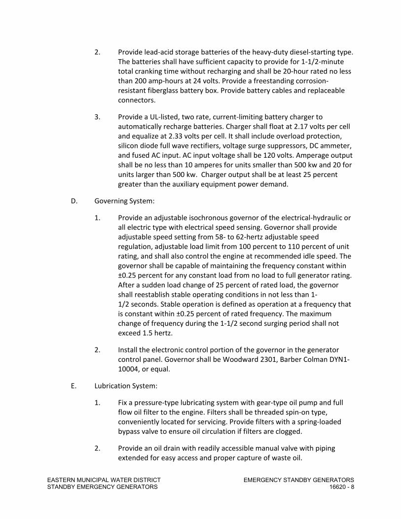
EASTERN MUNICIPAL WATER DISTRICT EMERGENCY STANDBY GENERATORS STANDBY EMERGENCY GENERATORS 16620 - 8
2. Provide lead-acid storage batteries of the heavy-duty diesel-starting type. The batteries shall have sufficient capacity to provide for 1-1/2-minute total cranking time without recharging and shall be 20-hour rated no less than 200 amp-hours at 24 volts. Provide a freestanding corrosion-resistant fiberglass battery box. Provide battery cables and replaceable connectors.
3. Provide a UL-listed, two rate, current-limiting battery charger to automatically recharge batteries. Charger shall float at 2.17 volts per cell and equalize at 2.33 volts per cell. It shall include overload protection, silicon diode full wave rectifiers, voltage surge suppressors, DC ammeter, and fused AC input. AC input voltage shall be 120 volts. Amperage output shall be no less than 10 amperes for units smaller than 500 kw and 20 for units larger than 500 kw. Charger output shall be at least 25 percent greater than the auxiliary equipment power demand.
D. Governing System:
1. Provide an adjustable isochronous governor of the electrical-hydraulic or all electric type with electrical speed sensing. Governor shall provide adjustable speed setting from 58- to 62-hertz adjustable speed regulation, adjustable load limit from 100 percent to 110 percent of unit rating, and shall also control the engine at recommended idle speed. The governor shall be capable of maintaining the frequency constant within ±0.25 percent for any constant load from no load to full generator rating. After a sudden load change of 25 percent of rated load, the governor shall reestablish stable operating conditions in not less than 1-1/2 seconds. Stable operation is defined as operation at a frequency that is constant within ±0.25 percent of rated frequency. The maximum change of frequency during the 1-1/2 second surging period shall not exceed 1.5 hertz.
2. Install the electronic control portion of the governor in the generator control panel. Governor shall be Woodward 2301, Barber Colman DYN1-10004, or equal.
E. Lubrication System:
1. Fix a pressure-type lubricating system with gear-type oil pump and full flow oil filter to the engine. Filters shall be threaded spin-on type, conveniently located for servicing. Provide filters with a spring-loaded bypass valve to ensure oil circulation if filters are clogged.
2. Provide an oil drain with readily accessible manual valve with piping extended for easy access and proper capture of waste oil.

EASTERN MUNICIPAL WATER DISTRICT EMERGENCY STANDBY GENERATORS STANDBY EMERGENCY GENERATORS 16620 - 9
F. Engine-Mounted Fuel System:
1. Provide an engine-mounted fuel filter with spin-on type replaceable elements, fuel pressure gauge, accessible manual shutoff valve, and engine-driven positive displacement pump.
2. Provide a water separator on the engine just ahead of the fuel filters to prevent condensation, or other water, present in the fuel from reaching the engine filters, pumps, or injectors. Construct of heat-resistant Lexan, with an aluminum-perforated baffle, for easy viewing of the amount of water contained. The fuel filter shall not require changing more frequently than once per year or every 250 hours, whichever comes first. Fuel/water separators shall not require draining more frequently than once per week.
G. Jacket Water Heater: Provide a UL-listed, unit-mounted thermal circulation-type water heater incorporating a self-contained thermostatic switch, controlled by the exit coolant temperature from the heater to maintain engine jacket coolant to 90°F in an ambient temperature of 30°F. The dual heater unit shall be single phase, 60 hertz, 240 volts, 2.0 kw. Heater shall be Chromalox or equal. Provide hand valves in the heater hoses to facilitate changing heating elements without draining the entire cooling system.
H. Safety Switches: Provide devices for indication and control of the following conditions at the generator control panel.
1. Low oil pressure (pre-alarm).
2. Low oil pressure (shutdown).
3. High water temperature (pre-alarm).
4. High water temperature (shutdown).
5. Overspeed (shutdown).
Overspeed trip and cranking termination shall be by a dual element electronic-type speed switch that operates on magnetic impulses from the flywheel ring gear or other engine-timed gear. Overspeed trip setting shall be 118 percent of synchronous speed. The low setting shall be used to automatically ensure continued engine cranking until the engine has reached 600 rpm, even if the oil pressure is up to an acceptable level at a lower speed.
I. Emissions: Provide the engine with emission control equipment to ensure that gaseous exhaust emissions (for NOx, HC, and CO) do not exceed the maximum levels established by the local Air Quality Management District.

EASTERN MUNICIPAL WATER DISTRICT EMERGENCY STANDBY GENERATORS STANDBY EMERGENCY GENERATORS 16620 - 10
These maximum levels shall be at the manufacturer’s rated speed and load as measured by SAE-J177 and SAE-J215 recommended practices. Verification of the ability to meet these emission specifications shall be submitted.
2.04 GENERATOR
A. General:
1. The generator shall be a 3-phase, 60-hertz, single-bearing, dripproof, rotating field, synchronous type, with 3-phase rotating armature brushless exciter. Provide Class F insulation on the stator and rotor. Further protect both with 100 percent epoxy varnish impregnation and an overcoat of resilient epoxy asphalt insulating material to increase resistance to abrasive dust or sand, high humidity, and light acidic, oil, or salt-laden atmospheres, as well as prevent fungus growth.
2. The wave form deviation factor of the line-to-line voltage at no load and balanced rated load at 0.80 power factor shall not exceed 5 percent. The rms of all harmonics shall be less than 3 percent and that of any one harmonic less than 2 percent at full rated load.
3. Conform to the applicable NEMA standards for motors and generators, MG-1. Base rating of generator on continuous operation at 0.80 power factor.
B. Regulator: The voltage regulator shall be a solid-state, volts per hertz type with 3-phase sensing and shall maintain a constant and stable generator output voltage within ±1 percent of nominal for all steady-state loads from no load to full load with isochronous speed control and ±2 percent with speed droop operation. A 5 percent variation in frequency and the effects of field heating shall not affect the unit’s regulation performance. Provide stability and voltage range adjustments.
2.05 STRUCTURAL STEEL BASE
A. Mount the engine-generator on a heavy-duty structural steel base. Provide holes for mounting bolts. Provide the structural steel base with means for lifting the unit for shipment and installation. Clearly identify lift points and total weight and permanently mark on the base.
B. Anchor the steel base to the foundation with an anchorage system designed to withstand seismic forces per the California Code of Regulations, Title 24, Part 2, Section 2312, Seismic Zone 4, with Z = 0.4, Cp = 0.67, and Ip = 1.5. The manufacturer shall submit calculations stamped and signed by a California-registered structural engineer or civil engineer.

EASTERN MUNICIPAL WATER DISTRICT EMERGENCY STANDBY GENERATORS STANDBY EMERGENCY GENERATORS 16620 - 11
C. Isolate the engine-generator from the structural steel base with rubber-in-shear isolators for units 225 kw and smaller. Isolate the engine-generator from the structural steel base with steel spring isolators for units 230 kw and larger.
D. The Contractor shall install vibration isolators between the unit base and the concrete foundation that are per the Plans and spring-type isolators with neoprene-jacketed pre-compressed molded fiberglass noise isolation pads, steel load plate, built-in leveling bolt, welded steel or cast housing, and high deflection steel springs. Isolators shall be Peabody Noise Control, Inc.; Kinetics brand, Type SM; or equal.
2.06 COOLING SYSTEM
A. Provide an engine-mounted radiator with blower-type fan sized to maintain full load operation continuously at the specified maximum ambient temperature. Equip the radiator with a 1-inch-wide duct adapter flange and low coolant level switch gauge. The radiator shall be able to produce the airflow required for proper cooling of the engine at full rated load with up to 1.0 inch of water resistance. Provide ductwork with flexible connection section between radiator duct flange and exhaust louver. Provide fan guard for protection of maintenance personnel as required by Cal/OSHA.
B. Ductwork shall be galvanized iron or steel sheets or aluminum sheets. Anchor ducts securely to the building and install so as to be completely free from vibration during engine operation. Brace and reinforce ducts with angles or other structural members. Internal ends of slip joints shall be installed in the direction of flow.
C. Flexible connection shall be wire-reinforced glass fabric. The connection shall be rendered practically airtight.
D. Fill the engine-cooling system with antifreeze/coolant recommended by engine manufacturer.
E. Provide a coolant drain with readily accessible manual valve with piping extended for easy access and proper capture of waste coolant.
2.07 EXHAUST SYSTEM
A. Exhaust system shall consist of a silencer, flexible exhaust fitting, exhaust piping, insulation, and mounting hardware.
B. Provide a chamber-type supercritical hospital grade silencer constructed of Type 304 stainless steel with a baked on silicon-based coating rated for 1100°F minimum. Silencer shall provide an average noise attenuation of 33 to 40 dBA.

EASTERN MUNICIPAL WATER DISTRICT EMERGENCY STANDBY GENERATORS STANDBY EMERGENCY GENERATORS 16620 - 12
Provide brackets, companion flanges, gaskets, and fasteners for mounting silencer. Silencer shall be as manufactured by Universal, Nelson, Riley-Beaird, or equal.
C. Silencer and exhaust pipe size shall be sufficient to ensure that measured exhaust back pressure does not exceed the maximum limitations specified by the generator set manufacturer.
D. Provide a seamless Type 316 stainless steel bellows-type flexible exhaust fitting at least 18-inches long.
E. Exhaust piping shall be carbon steel. Provide flanged or welded type fittings. Provide sufficient flanged fittings to permit the system to be entirely dismantled in sections. Use sweep elbows with a radius at least three times the pipe diameter.
F. Provide vertical discharge tailpipe. Cap with a counterbalanced rain cap.
G. Cover the exhaust manifolds with an expanded metal guard for personnel protection.
H. Cover the silencer and interior exhaust piping with lagging to maintain a surface temperature not to exceed 150°F. Lagging shall be calcium silicate insulation with banded aluminum jacket.
2.08 DIESEL PARTICULATE FILTER
A. Provide a passive type diesel particulate filter system with all necessary appurtenances, including but not limited to the particulate filter, filter controller, electric heater and permanent load bank, such that the generator emissions levels meet Air Quality Management District (AQMD) requirements.
B. DPF should be at least a Califoria Air Resources Board (CARB) Level 3 Verified with a particulate matter (PM) reduction greater than 85%.
C. The CARB Executive order for the DPF should either list compatibility to the generator engine family name or approval shall be granted by AQMD.
D. CARB verified Diagnostic Module shall be provided to continuously monitor temperature and backpressure. Diagnostic Module shall have LED visual indication and dry contact for customer alarms when backpressure and temperature exceeds normal operating conditions.
E. DPF alarm system shall be provided with an Ethernet port connection to support alarm programming, trouble shooting and downloading data.

EASTERN MUNICIPAL WATER DISTRICT EMERGENCY STANDBY GENERATORS STANDBY EMERGENCY GENERATORS 16620 - 13
2.09 FUEL STORAGE SYSTEM
A. Provide a sub-base fuel tank for the generator set, sized to allow full load operation of the generator as indicated on the plans. The fuel tank shall be UL 142 listed and labeled. Installation shall be in compliance with NFPA 37.
B. The fuel tank shall be double walled, steel construction and include the following features:
1. Emergency tank and basin vents.
2. Mechanical level gauge.
3. Fuel supply and return lines, connected to the generator set with flexible fuel lines as recommended by the engine manufacturer and in compliance with UL 2200 and NFPA 37 requirements.
4. Leak detection provisions, wired to the generator set control for local and remote alarm indication.
5. High and low fuel level float switches to indicate fuel level. Wire switches to generator control for local and remote indication of fuel level.
6. Fuel level transmitter: Provide an ultrasonic level transmitter capable of continuous fuel level measurement with a 4-20mA output signal as shown on the Drawings. Level transmitter shall be as manufactured by Flowline, or approved equal.
7. Minimum 5-gallon capacity spill container at fuel fill point.
8. Basin drain.
9. Integral lifting provisions.
2.10 GENERATOR CONTROL PANEL
A. Provide a NEMA 1, vibration isolated, dead front, 16-gauge steel control panel with lockable hinged cover. Mount and wire the control panel to the engine-generator set. The panel shall include the following equipment:
1. Voltmeter, 3-1/2 inches, 2 percent accuracy with 3-phase fuse protection. Digital meters are acceptable.
2. Ammeter, 3-1/2 inches, 2 percent accuracy. Digital meters are acceptable.
3. Ammeter-voltmeter phase selector switch. Digital meters are acceptable.

EASTERN MUNICIPAL WATER DISTRICT EMERGENCY STANDBY GENERATORS STANDBY EMERGENCY GENERATORS 16620 - 14
4. Frequency meter, 3-1/2 inches, dial type. Digital meters are acceptable.
5. Kilowatt meter.
6. Oil pressure gauge.
7. Water temperature gauge.
8. Oil temperature gauge.
9. Running time meter.
10. Instrument transformers.
11. Automatic starting controls.
12. Voltage level adjustment rheostat.
13. Dry contacts for remote alarms wired to terminal strips from the following alarms:
a. Fault indicator lights with press to test feature for low oil pressure.
b. High coolant temperature.
c. Low coolant level.
d. Overspeed.
e. Overcrank.
f. Run dry contact.
g. Generator common fail.
h. In auto.
i. Breaker position (not closed).
j. Fuel level.
14. Visual alarm indicators for impending shutdown from low oil pressure and high coolant temperature.
15. 80-dB alarm horn with silence switch.
16. Three-position function switch marked “manual,” “off/reset,” and “auto.”

EASTERN MUNICIPAL WATER DISTRICT EMERGENCY STANDBY GENERATORS STANDBY EMERGENCY GENERATORS 16620 - 15
17. Panel illumination lights and switch.
18. Electric governor control unit.
19. Generator voltage regulator as previously specified.
20. Low battery voltage alarm light.
21. 4 to 20mA signal outputs for oil pressure, coolant temperature, and battery voltage.
22. Emergency stop button on control panel and an additional emergency stop button on the side of the engine-generator mounted approximately 48 inches above finished floor.
B. Meters, circuit breakers, control switches, and current transformers shall be General Electric, Cutler-Hammer, or equal. Pilot lights and push buttons shall be oil tight type. An annunciator panel may be provided in lieu of oil tight pilot lights. Digital instrumentation is acceptable in lieu of meters and lamps.
C. Provide relays and timing devices with clear polycarbonate dust covers. Devices shall be plug-in type with hold down spring retainers. Output contacts shall be rated 10 amperes at 24-volts DC.
D. Provide engraved or etched nameplates to show position of switches and function of pilot lights, push buttons, and meters. Do not provide embossed tape.
E. Provide fully automatic generator set start-stop controls in the generator panel. Controls shall operate as follows:
1. When the function switch is in automatic position and upon closure of a set of external contacts or when the switch is in manual position, the engine shall automatically crank. An adjustable cranking limiter shall allow from 2 to 5 cycles of 10 seconds’ crank followed by 10 seconds’ rest. If the engine fails to start after this time, the starting circuit shall be locked out and the overcrank shutdown light initiated.
2. When operating in the automatic mode and the remote engine run contact opens, the engine shall shut down.
3. Initiation of any safety shutdown shall immediately stop the engine and light the appropriate light. Upon correction of the fault, the shutoff system shall be made operable by moving the function switch to off/reset and then back to the “auto” position.

EASTERN MUNICIPAL WATER DISTRICT EMERGENCY STANDBY GENERATORS STANDBY EMERGENCY GENERATORS 16620 - 16
2.11 MAIN LINE CIRCUIT BREAKER
A. Provide a main line molded case circuit breaker sized as shown on the Drawings and in accordance with the NEC (two main breakers for Twin Lake Pump Station as indicated on the plans). Install on the generator in a NEMA 1 enclosure or in the generator control panel to function as a load circuit interrupting and protection device. It shall operate both manually for normal switching function and automatically during overload and short-circuit conditions. Circuit breaker shall trip free of the handle. The handle position, or a luminescent flag, shall indicate “off,” “on,” or “tripped” breaker positions. The trip unit for each pole shall have elements providing inverse time delay during overload conditions and instantaneous magnetic tripping for short-circuit protection. Insulated neutral terminals and a ground terminal shall be provided and marked. The circuit breaker shall meet standards established by UL, NEMA, and NEC. Do not use generator exciter field circuit breakers in lieu of a main line circuit breaker.
B. Circuit breaker shall be equipped with an auxiliary contact to provide “Generator Circuit Breaker Not Closed” input to the PLC.
2.12 TORSIONAL VIBRATION ANALYSIS
A. Submit a torsional vibration analysis of the engine-generator combination, showing it free of harmful torsional vibration stresses within ±10 percent of its normal operating speed range, the natural frequency, critical speeds, relative amplitudes of angular displacement, and approximate nodal locations of the complete elastic system of the engine and driven equipment.
2.13 SOUND ATTENUATING ENCLOSURE
A. Provide weatherproof (NEMA 3R) Level II, Stage 2 sound attenuating enclosure that allows the generator set to operate at full rated load in an ambient temperature of up to 120°F. Enclosure shall be 14-gauge steel construction with corrosion resistant hardware and hinged, lockable doors. Enclosure shall include internally mounted muffler, sound insulating panels and rodent barriers. Insulation shall be non-hydroscopic material. All electrical and fuel stub-ups shall be within enclosure. Enclosure shall comply with all applicable NEC and UL 2200 requirements.
B. The sound enclosure shall produce sound pressure levels at the indicated measured distances from the enclosure not to exceed those listed below. The sound level shall not exceed 67 dBA when measured at the site property line adjacent to the residential homes.

EASTERN MUNICIPAL WATER DISTRICT EMERGENCY STANDBY GENERATORS STANDBY EMERGENCY GENERATORS 16620 - 17
Sound Pressure Levels (dBA) at… 1 m (3.3 ft) 7 m (23 ft) 15 m (50 ft)
89.1 76.1 70.1
2.14 LOAD BANK
A. Provide a radiator mounted resistive load bank.
1. Provide load bank per the requirements of the National Fire Protection Association (NFPA) for emergency stand-by power systems.
2. Local and remote controls
3. Load Bank shall be capable of full automatic operation.
4. Indicating lights: Normal operation and cooling feature
5. Branch circuit contactors each step or each 50kw circuit max
6. Full rated copper bus bar with oversized terminal junction box
7. Radiator mounted – galvanized steel construction.
8. Coordinate size of load bank with generator and DPF manufacturers. Load bank minimum size shall be 60% of generator rated capacity.
9. 480v, 3-phase, 60hz
PART 3 - EXECUTION
3.01 FACTORY TESTING
A. Perform factory tests in the presence of the Owner’s Representative prior to shipment. Provide 7-days’ advance notice of test date. Include the following tests.
B. Demonstrate proper operation of all safety devices, shutdown features, and alarms. Conduct load tests utilizing resistive load banks as follows:
Load Hours
½ 1 ¾ 1
Full 4

EASTERN MUNICIPAL WATER DISTRICT EMERGENCY STANDBY GENERATORS STANDBY EMERGENCY GENERATORS 16620 - 18
C. Record current, voltage, frequency, water temperature, and lube oil pressure every 15 minutes.
D. Verify fuel consumption rate at 1/2, 3/4, and full loads. Note fuel consumption rates on a label located at fueling point.
E. The manufacturer shall pay reasonable food, transportation and lodging expenses for up to three Owner personnel to witness testing.
3.02 INSTALLATION
A. Installation will be done by the installation contractor. The manufacturer shall provide written installation instructions with shop drawings. The manufacturer shall coordinate with the installation contractor regarding installation of the engine-generator set foundations and fuel and piping systems and shall verify that all components specified herein are installed in accordance with the generator set manufacturer’s written requirements. Foundation blocks, anchor bolt layouts, and piping may have to be modified from those shown on the Plans. Such work shall be at the Contractor’s expense.
B. Anchor bolts for the engine-generator set bases shall be cast-in-place. The engine manufacturer shall provide anchor bolts and select anchor bolt material.
C. Fill the tanks with No. 2-D diesel fuel meeting ASTM D 975-60T. After field testing is complete, refill the tanks.
3.03 PIPING
A. Pitch horizontal runs of exhaust pipe away from the engine. Provide condensate traps with petcocks or valves at low spots in the exhaust system.
3.04 PAINTING AND COATING
A. Coat non-insulated exhaust pipes and silencers with a baked silicon-based coating rated for 1100°F minimum.
3.05 START-UP
A. On completion of the installation, the initial start-up shall be performed by a factory-trained service representative of the engine supplier, who shall thoroughly inspect, operate, test, and adjust the equipment. The inspection shall include the soundness of all parts, completeness of all details, proper operation of all components with special emphasis on safety devices, correctness of the settings, proper alignments, and correct phase rotation to match other sources.
B. DPF and load bank startup testing and commissioning shall be performed by a factory trained service representative or the engine supplier.

EASTERN MUNICIPAL WATER DISTRICT EMERGENCY STANDBY GENERATORS STANDBY EMERGENCY GENERATORS 16620 - 19
C. Field tests shall include the following:
1. Simulate power failure by tripping the main breaker and demonstrate complete manual and automatic start, load, unload, and stop sequence of the engine-generator.
2. Conduct a 2-hour run, utilizing maximum available load. If available load is less than 75 percent of the generators’ rating, provide load bank loads to obtain 75 percent generator loading (minimum).
3. Retest all alarms and shutdown features.
3.06 SCHEDULED OIL SAMPLING
A. In order to forecast and minimize engine failure, the supplier of the equipment shall provide a quarterly (every 3 months) oil sampling analysis for a period of 2 years from date of acceptance. This scheduled oil sampling shall be of the atomic absorption spectrophotometry method as opposed to the spectographic analysis method and shall be accurate to within ±1 ppm for the following elements: lead, iron, chromium, copper, aluminum, and silicon. In addition, test the sample for the presence of water, fuel, dilution, and antifreeze.
B. Provide equipment needed to take oil samples in a kit at the time of acceptance. Include a sample gun kit, bottles, mailers, and written instructions.
C. Provide immediate notification by telephone or fax to the Owner when analysis results show any critical reading. If readings are normal, provide a report by mail showing that the oil quality is within established requirements.
D. This scheduled oil sampling program shall be available to the Owner at the supplier’s normal rate, after the mandatory 2 years, and shall be continued thereafter at the Owner’s option.
3.07 DELIVERY, STORAGE AND HANDLING
A. The manufacturer shall deliver the assembly to the field just prior to installation as determined by the installation contractor and as approved in writing by the Owner.
B. The manufacturer shall store the assembly within a building protected from the elements for a period up to 365 calendar days.
C. The installation contractor shall accept the delivery of the assembly and will take responsibility for them from that point on and will coordinate with the manufacturer to ensure proper installation of the system. The manufacturer shall coordinate with the installation contractor as needed to provide a complete and functional installation that is covered by the manufacturer’s warranty.

EASTERN MUNICIPAL WATER DISTRICT EMERGENCY STANDBY GENERATORS STANDBY EMERGENCY GENERATORS 16620 - 20
END OF SECTION

Revised 04/14/16
SPECIFICATIONS - DETAILED PROVISIONS Section 16950 - Custom Control Panels
C O N T E N T S
PART 1 - GENERAL ....................................................................................................................... 1
1.01 DESCRIPTION .............................................................................................................. 1 1.02 RELATED WORK SPECIFIED ELSEWHERE ......................................................................... 1 1.03 SUBMITTALS ............................................................................................................... 1 1.04 DESIGN AND GENERAL REQUIREMENTS ........................................................................ 6 1.05 QUALITY ASSURANCE................................................................................................... 8 1.06 DELIVERY, STORAGE, AND HANDLING ........................................................................... 9
PART 2 - PRODUCTS ................................................................................................................... 10 2.01 MANUFACTURERS ..................................................................................................... 10 2.02 MANUFACTURED ENCLOSURES .................................................................................. 10 2.03 ENCLOSURE LIGHTS AND RECEPTACLES ....................................................................... 16 2.04 ENCLOSURE HEATING AND VENTILATION .................................................................... 16 2.05 CONTROL DEVICES AND COMPONENTS ....................................................................... 18 2.06 MARKERS AND NAMEPLATES ..................................................................................... 23 2.07 WIRING METHODS ..................................................................................................... 25 2.08 SPARE PARTS............................................................................................................. 26
PART 3 - EXECUTION .................................................................................................................. 27 3.01 FACTORY TESTS ......................................................................................................... 27 3.02 SITE TESTS ................................................................................................................. 28 3.03 CONTROL PANEL MOUNTING ..................................................................................... 29 3.04 MANUFACTURER'S SERVICES ...................................................................................... 30


Custom Control Panels Section 16950 – 1
SECTION 16950
CUSTOM CONTROL PANELS PART 1 - GENERAL
1.01 DESCRIPTION
Contractor shall furnish and install custom control panels as specified herein, shown on the Drawings, and where specified in other Specification Sections.
A. Custom control panels include, but are not limited to, Unit Control Panels (UCPs), Local
Control Panels (LCPs), and Programmable Logic Controllers (PLCs). Custom control panels include control panels designed and supplied by equipment manufacturers as part of packaged equipment and equipment systems.
B. The Instrumentation and Control Subcontractor (per Section 17005) shall design or
review design of custom control panels and coordinate the interface between custom control panels, MCCs, other control panels, instrumentation, and District's SCADA system (including remote telemetry units, RTUs).
1.02 RELATED WORK SPECIFIED ELSEWHERE
A. The Contract Documents are a single integrated document, and as such all Divisions and Sections apply. It is the responsibility of the Contractor and its Subcontractors to review all sections to ensure a complete and coordinated project.
B. Related Specification Sections include, but are not limited to, the following:
1. Sections of the Specifications specifying equipment and/or systems requiring electrical power and/or control.
2. Division 16 – Electrical
3. Division 17 – Instrumentation and Controls 1.03 SUBMITTALS
All submittals shall be in accordance with the General Conditions and requirements specified herein.

Custom Control Panels Section 16950 – 2
A. Shop Drawings
Contractor shall prepare and submit complete and organized information, drawings, and technical data for all equipment and components. All drawings shall be legible and reduced to a maximum size of 11” x 17” for inclusion within the submittal. Shop drawings shall include, but not be limited to, the following: 1. Detailed Bill of Materials for all control panel hardware, and associated materials
and components, listing: manufacturer's name, quantity, description, size, and catalog/part number.
2. Complete documentation for all control panel equipment and associated
components, including: manufacturer's product literature, specifications, performance capabilities, features and accessories, dimensions and weights, illustrations, and data in sufficient detail to demonstrate compliance with Specification requirements. Manufacturer’s literature and data shall be marked to clearly delineate all applicable information and crossing out all inapplicable information.
3. Control panel fabrication drawings (plan view, and interior and exterior elevation
views) with all equipment and components clearly shown, dimensioned, and labeled. Drawings shall show the equipment and component assembly, clearances, and locations for conduits/conductors and anchor bolts. Devices shall be identified with the same marking as used on the schematic diagrams. The drawings shall include a detailed layout of all door mounted pilot devices and instruments.
4. Enclosure construction, NEMA Type, and type and gauge of materials. 5. Detailed descriptions of control panel equipment, equipment installation
requirements, and heat dissipations. 6. System configuration with power circuit single line diagrams, grounding circuits,
circuit breakers, and fuses. 7. Control schematics, ladder diagrams, and interconnection drawings (see
Part 1.03.B herein) for additional requirements. 8. Nameplate data including the nameplate material, heights of letter and
inscriptions. 9. Spare parts list as specified in this Section.

Custom Control Panels Section 16950 – 3
10. Manufacturer's installation instructions including receiving, handling, and
storage requirements.
B. Control Diagrams
1. Schematic diagrams shall show the equipment serial number, the purchaser's drawing number, purchase order number, or similar identification which will indicate the particular equipment to which the diagrams apply.
2. Diagrams shall show all equipment and components in the electrical system
including internal wiring of subassemblies. Diagrams shall clearly identify internal and external devices, and all remote contacts and signals. Show all interconnections between power sources and device elements of a particular system or equipment, and all interlocks with other equipment/systems in a manner that fully indicates the circuit function and operation. Show all panel terminal block identification numbers and all wire numbers. Show all intermediate terminations between field elements and panels. Diagrams of subassemblies may be furnished on separate sheets.
3. Identify each device by a unique number or number-letter combination. 4. Conductor Identification: Identify each conductor by a unique number, letter, or
number-letter combination. Consecutive numbering is preferred. Each conductor shall have the same identification at all terminals and tie points. All conductors connected to the same terminal or tie point shall have the same identification. Where multi conductor cable is used, a color code may be used to supplement the above identification. Where color coded multi conductor cable is used for wiring identical components, such as limit switches, the color code used shall be consistent and charted on related diagrams.
5. Provide a schematic diagram for each electrical system. The schematic diagram
shall be drawn between vertical lines which represent the source of control power. Show control devices between these lines. Show actuating coils of control devices on the right-hand side. Show contacts between the coils and the left vertical line.
a. Where the internal wiring diagrams of subassemblies are furnished on
separate sheets, they shall be shown as a rectangle in the schematic diagram with all external points identified and cross-referenced to the separate sheets of the control circuit. Show coils and contacts internal to the subassemblies in the rectangle connected to their terminal points.
b. For clarity, show control device symbols in the order in which the
controls are positioned on the diagram.

Custom Control Panels Section 16950 – 4
c. Use a cross-referencing system in conjunction with each relay coil so that associated contacts may be readily located on the diagram. Where a relay contact appears on a sheet separate from the one on which the coil is shown, describe the purpose of the contact on the same sheet.
d. Show all spare contacts. e. Show limit, pressure, level, flow, temperature, and similar switch symbols
on the schematic diagram with all utilities turned off (electric power, air, gas, oil, water, lubrication, etc.) and with the equipment at its normal starting position.
f. Show contacts of multiple contact devices (e.g., selector switches and
pushbuttons) on the line of the schematic diagram where they are connected in a circuit. Indicate a mechanical connection between the multiple contacts by a dotted line or arrow.
g. Additional charts or diagrams may be used to indicate the position of
multiple contact devices such as limit, pressure, level, and selector switches.
h. Show the purpose or function of all switches adjacent to the symbols. i. Show the purpose or function of controls such as relays, starters,
contactors, solenoids, subassemblies, and timers on the diagram adjacent to their respective symbols. Show the number of positions of the solenoid valve adjacent to the valve solenoid symbol.
C. Operation and Maintenance Manual
Contractor shall submit a detailed Operation and Maintenance (O&M) Manual for all custom control panels specified herein and shown on the Drawings. The O&M Manual shall be provided in accordance with the requirements of the District's General Conditions, Specification Section 01430, and as specified herein. The O&M Manual shall include, but not be limited to, the following: 1. Equipment Performance Data and Drawings
a. Detailed Bill of Materials for all control panel equipment and components, listing: manufacturer's name, quantity, description, size, range, and model/part number.

Custom Control Panels Section 16950 – 5
b. Manufacturer's product literature, specifications, performance
capabilities, features and accessories, and illustrations. c. Manufacturer’s data and drawings showing dimensions, physical
configurations, installation and mounting details, and wiring schematics. d. Control ladder diagrams and wiring schematics. Loop diagrams for each
monitoring and/or control loop.
2. Installation and Operation Requirements
a. Complete, detailed installation and operation instructions for all control panel equipment and components.
3. Service and Maintenance Data
a. Service and maintenance data shall include all information and instructions required by District's personnel to keep the control panel and all associated components functioning properly under the full range of operating conditions.
b. Explanation with illustrations as necessary for each service and
maintenance task. c. Recommended schedule of service and maintenance tasks. d. Troubleshooting instructions. e. List of maintenance tools and equipment. f. Recommended spare parts list. g. Names, addresses and phone numbers of all manufacturers and
manufacturer's local service representatives.
D. Final O&M Manual Upon successful completion of startup and initial operation, Contractor shall submit a Final O&M Manual in accordance with the requirements of the District’s General Conditions, Specification Section 01430, and as specified herein. In addition to the O&M Manual requirements specified above, the Final O&M Manual shall be supplemented with the as-built drawings (including all field changes) for all control panel wiring and loop diagrams.

Custom Control Panels Section 16950 – 6 1.04 DESIGN AND GENERAL REQUIREMENTS
A. Power for Control Panels and Interconnected Devices 1. All control panels shall be supplied with 480 VAC, 3-phase, 240 VAC Single Phase
or 120 VAC Single Phase 60 Hz. power, as shown on the Drawings. All control panels shall be designed to minimize sources of control power (foreign power) from other panels.
2. Each control panel shall have a flange mounted disconnecting circuit breaker
operable from the control panel front and interlocked with the enclosure door, to be used to isolate the control panel from the power supply.
3. The panel shall have a nameplate identifying the circuit breaker feeding the
panel. Warning labels shall be provided identifying sources of foreign power to be disconnected prior to accessing the control panel.
4. The control voltage within the control panel controls shall be 120 VAC. Where
the electrical power supply to the control panel is 240 VAC single phase or 480 VAC 3-phase, as shown on the Drawings, the control panel shall be provided with control power transformers, overcurrent protection, and power supplies to convert supply voltage to utilization voltage.
5. The control panel shall be the source of power for all 120 VAC devices
interconnected with the control panel including, but not limited to solenoid valves, instruments, and transmitters both mounted in the control panel and remotely connected to the control panel.
B. Enclosure General Requirements
Unless indicated otherwise on the Drawings, or in the individual packaged equipment specification sections, control panels shall comply with the following requirements:
1. Control panels enclosures shall meet, or exceed, area classifications
requirements per NEC. 2. Control panel enclosures shall have the following NEMA ratings:
a. Enclosures installed indoors shall be rated NEMA 12. b. Enclosures installed outdoors shall be rated NEMA 4X. c. Enclosures installed indoors in wet or corrosive areas shall be rated
NEMA 4X.

Custom Control Panels Section 16950 – 7
d. Enclosures installed indoors in hazardous areas shall be rated NEMA 7. e. Enclosures installed outdoors in hazardous areas shall be rated NEMA 4
and NEMA 7.
3. Control panels shall be either freestanding, pedestal-mounted, wall-mounted, or equipment skid-mounted, as specified in the individual packaged equipment specification sections or indicated on the Drawings.
4. Internal control components shall be mounted on an internal back-panel. 5. Each source of foreign control voltage shall be isolated by providing fuses on a
separate terminal block, clearly labeled for incoming foreign control voltage. 6. Discrete outputs from the control panel shall be provided by electrically isolated
contacts rated for 5 A (minimum) at 120 VAC. Output isolation shall be provided through interposing relays or PLC relay output cards (if applicable).
7. Analog inputs and outputs shall be an isolated 4-20 mA 2-wire signal with power
supply, power supply pilot light, and fuses. 8. Programmable Logic Controllers (PLCs) may be supplied in lieu of hardwired
relay logic with the District's approval or if specified in the specification section for the specific equipment. The PLC shall be in accordance with Section 17010, Programmable Logic Controller.
9. All control panel mounted indicating lights, switches, and operator interface
devices shall be mounted at least 3 feet above the finished floor elevation, but no more than 6 feet above the finished floor elevation.
10. Terminals shall be mounted vertical and locations of terminals and wireways
shall be coordinated to account for conduit entrances. 11. Control panels that contain circuit breakers, combination full-voltage motor
starters, soft starters, variable frequency drives, or other motor controls shall comply with the requirements Section 16480, Motor Control Centers, Switchboards, and Panelboards, and Section 16160, Variable Frequency Drives.
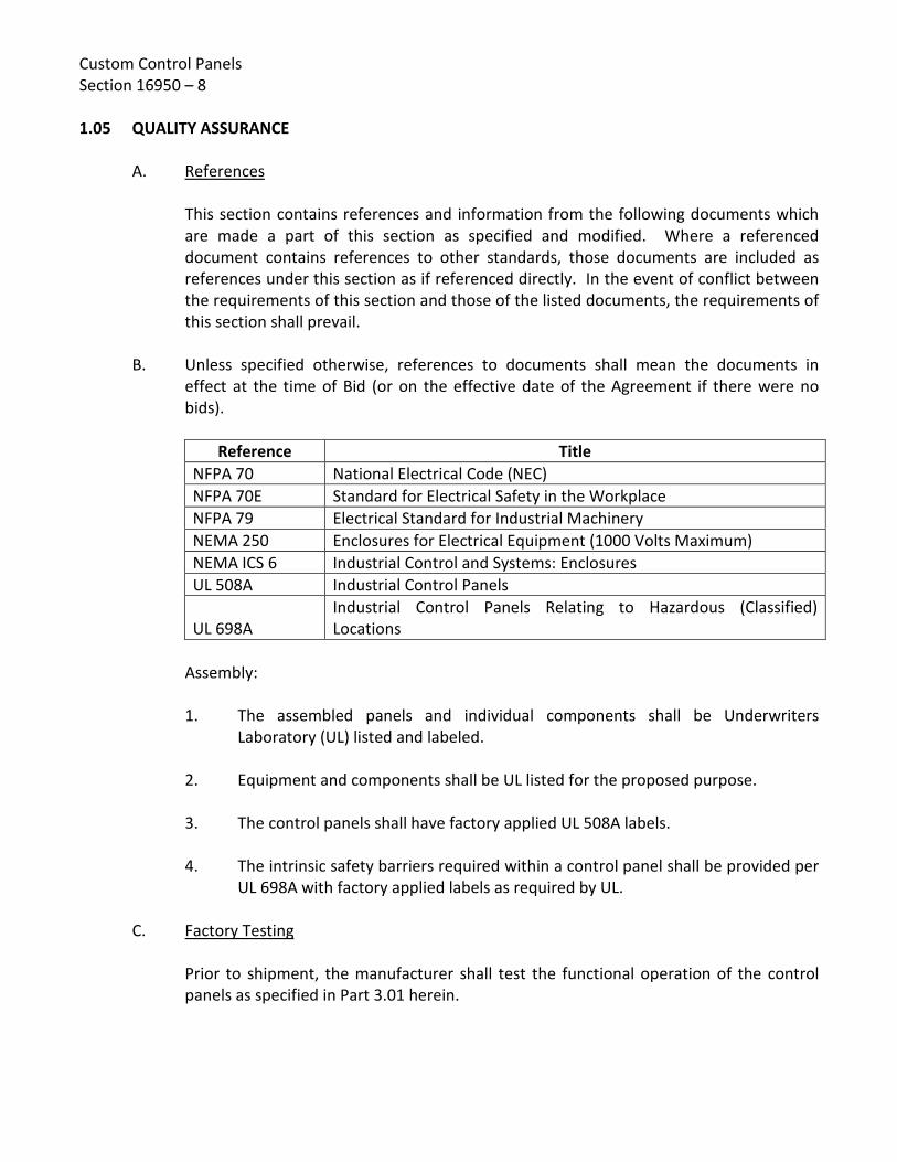
Custom Control Panels Section 16950 – 8 1.05 QUALITY ASSURANCE
A. References
This section contains references and information from the following documents which are made a part of this section as specified and modified. Where a referenced document contains references to other standards, those documents are included as references under this section as if referenced directly. In the event of conflict between the requirements of this section and those of the listed documents, the requirements of this section shall prevail.
B. Unless specified otherwise, references to documents shall mean the documents in effect at the time of Bid (or on the effective date of the Agreement if there were no bids).
Reference Title
NFPA 70 National Electrical Code (NEC) NFPA 70E Standard for Electrical Safety in the Workplace NFPA 79 Electrical Standard for Industrial Machinery NEMA 250 Enclosures for Electrical Equipment (1000 Volts Maximum) NEMA ICS 6 Industrial Control and Systems: Enclosures UL 508A Industrial Control Panels
UL 698A Industrial Control Panels Relating to Hazardous (Classified) Locations
Assembly:
1. The assembled panels and individual components shall be Underwriters Laboratory (UL) listed and labeled.
2. Equipment and components shall be UL listed for the proposed purpose. 3. The control panels shall have factory applied UL 508A labels. 4. The intrinsic safety barriers required within a control panel shall be provided per
UL 698A with factory applied labels as required by UL.
C. Factory Testing
Prior to shipment, the manufacturer shall test the functional operation of the control panels as specified in Part 3.01 herein.

Custom Control Panels Section 16950 – 9
D. Environmental Sustainability
1. All indoor and outdoor panels and instrument enclosures shall be suitable for
operation in the ambient conditions associated with the locations designated in the Contract Documents.
2. Unless specified otherwise, heating, cooling and dehumidifying devices shall be
provided in order to maintain all instrumentation components to within a range equal to 20 percent above the minimum and 20 percent below the maximum of the rated environmental operating ranges. All required power wiring and temperature controls shall be provided for these devices.
3. Enclosures suitable for the designated environment shall be furnished. 4. All control panels and instrumentation enclosures in hazardous areas shall be
suitable for use in the particular hazardous or classified location in which it is to be installed.
1.06 DELIVERY, STORAGE, AND HANDLING
A. Delivery
All control panels shall be crated for shipment using heavy framework and skids:
1. Each panel shall further be cushioned satisfactorily to protect the finish of the instruments and panel during shipment.
2. All instruments, which are shipped with the panel, shall further have suitable
shipping stops and cushioning material installed in a manner to protect instrument parts, which could be damaged due to mechanical shock during shipment.
3. Large panel units and/or panel units weighing over 100 lbs. shall be provided
with removable lifting lugs to facilitate handling.
B. Storage and Handling
Control panels shall be stored and handled in accordance with the manufacturer's instructions and requirements and in a manner to protect the panel from the elements. Panels shall be handled in a manner to protect the components and enclosures.

Custom Control Panels Section 16950 – 10 PART 2 - PRODUCTS 2.01 MANUFACTURERS
A. Control panel enclosures shall be standard manufactured enclosures, whenever possible, and shall be as manufactured by Hoffman Engineering, Rittal, Stalin, or equal.
B. Dimensions
1. The Instrumentation and Control Subcontractor (ICS) and/or manufacturer of the
packaged equipment system shall be responsible to design and size all panel enclosures based upon:
a. Available space in area, as indicated on the Drawings. b. Equipment and device requirements for components located within the
control panel enclosure. 2. The size of the control panel enclosures as indicated on the Drawings is based on
preliminary, non-certified, information and as such these sizes are to be used as a general guideline.
3. A narrow or wide panel enclosure shall be provided if necessary to
accommodate the available space. A larger enclosure shall be provided if necessary to accommodate the equipment, devices, and appurtenances located within the panel.
2.02 MANUFACTURED ENCLOSURES
A. Type NEMA 1 and NEMA 12 Enclosures for Indoor Installation
1. Unless specified otherwise, enclosures rated NEMA 12 shall be provided for all indoor panels located in dry, non-corrosive areas. Where panels are located in dry, non-corrosive areas and are required to be ventilated for cooling (fan or non-fan cooled), enclosures shall be rated NEMA 1 gasketed.
2. NEMA 1 gasketed enclosures shall be designed to house electrical controls,
terminals, and instruments and shall provide protection from dust and dirt. 3. NEMA 12 enclosures shall be designed to house electrical controls, terminals,
and instruments, and shall provide protection from dust, dirt, and oil.

Custom Control Panels Section 16950 – 11
4. Enclosure minimum construction requirements shall be as follows:
a. Seams continuously welded and ground smooth. b. Door and body stiffeners as needed to make a rigid enclosure. c. Heavy gauge continuous hinge. d. Rolled lip around 3 sides of the door and all sides of the enclosure
opening to prevent migration of liquids and contaminants into enclosure. e. Oil-resistant gasket attached to door with oil-resistant adhesive. Gasket
to seal against roll lip on the enclosure opening. f. Interior back panel held in place by collar studs welded to enclosure.
Back panel shall be full size, constructed of 10 gauge steel with stiffeners as required. Provide split back panel where specified or indicated on the Drawings.
g. Door window where specified or indicated on the Drawings:
i) Safety plate glass. ii) Held in place by rubber locking seal. iii) Sized to allow full view of alphanumeric display, operator
interface, PLC Human-Machine Interface (HMI), etc. h. Door panel cutouts for instruments, devices, and windows shall be cut,
punched, or drilled and smoothly finished with rounded edges. Reinforce around cutouts with steel angles or flat bars for large panel cutouts such as for HMIs and for pilot device groupings where the removed metal exceeds 50 percent of the available metal in an area bound by a 3-inch envelope around said pilot devices.
i. Finish for NEMA 1 and NEMA 12 Enclosures
i) All steel parts shall be provided with UL listed acrylic/alkyd baked enamel paint finish or TGIC powder coat, except plated parts used for ground connections. All painted parts shall undergo a multi-stage treatment process, followed by the finishing paint coat.

Custom Control Panels Section 16950 – 12
ii) Pre-treatment shall include: a) Hot alkaline cleaner to remove grease and oil.
b) Iron phosphate treatment to improve adhesion and corrosion resistance
iii) The paint shall be applied using an electro-deposition process to
ensure a uniform paint coat with high adhesion. iv) The standard paint finish shall be tested to UL 50 per ASTM B117
(5% ASTM Salt Spray) with no greater than 0.125 inch loss of paint from a scribed line.
v) Paint color for enclosures shall be #49 medium light gray or #61
dark gray per ANSI Standard Z55.1 (60-70 gloss) on all exterior surfaces, unless specified otherwise. All unit interior surfaces shall be painted white for better visibility inside the unit.
vi) Panels that are in the same room as motor control centers
switchboards, etc. shall be of the same color as the motor control center or switchboards so that the control panel blends into the lineup.
j. Manufacturer's standard gauge steel. k. Each door to have a three-point latching mechanism and padlocking
handle with rollers on the ends of the latch rods. l. Print pocket inside door which shall be furnished with final as-built wiring
diagrams and all applicable manufacturer warranties. m. Heating and cooling per Part 1.05.D and Part 2.04 herein. n. Heavy duty lifting eyes for all free standing panels. o. Free standing, wall mount, or with floor stands or legs as indicated on the
Drawings. p. With flange mounted, disconnect for incoming power. q. Hinges: steel piano-type running full length of doors.

Custom Control Panels Section 16950 – 13
r. Copper ground bus bar 1/4-inch x 1-inch with solderless connectors for all
equipment grounds. s. Bonding and grounding kit, including all cable and mounting hardware
required to ground equipment to the door and body of the enclosure.
B. Type NEMA 4X Enclosures for Outdoor and Indoor (Wet or Corrosive Locations) Installation
1. Unless specified otherwise, enclosures rated NEMA 4X shall be provided for all
outdoor panels and indoor panels located in wet, corrosive areas. 2. NEMA 4X enclosures shall be designed to house electrical controls, terminals,
and instruments and shall provide protection from dust, dirt, oil, water, and corrosion.
3. In general, NEMA 4X enclosures shall be constructed of stainless steel. NEMA 4X
enclosures constructed of non-metallic fiberglass reinforced polyester resin shall be provided only where specifically indicated on the Drawings or specified in individual specification sections for packaged equipment systems.
4. Minimum construction requirements for stainless steel enclosures shall be as follows:
a. Type 316 stainless steel, 14-gauge minimum. b. Seams continuously welded and ground smooth. c. Door and body stiffeners as needed to make a rigid enclosure. d. Heavy gauge continuous hinge. e. Rolled lip around three sides of the door and all sides of the enclosure
opening to prevent migration of liquids and contaminants into enclosure. f. Oil-resistant gasket attached to door with oil-resistant adhesive. Gasket
to seal against roll lip on the enclosure opening. g. Interior back panel held in place by collar studs welded to enclosure.
Back panel shall be full size, constructed of 10 gauge steel with stiffeners as required. Provide split back panel where specified or indicated on the Drawings.

Custom Control Panels Section 16950 – 14
h. Unless specified otherwise or indicated otherwise on the Drawings, panels shall be provided with interior swing-out door for:
i) Mounting switches, lights, devices, and HMIs. ii) A window shall be provided in the exterior door for view of
interior lights, devices, and instruments if indicated on the Drawings.
i. Door panel cutouts (exterior and swing-out doors) for instruments,
devices, and windows shall be cut, punched, or drilled and smoothly finished with rounded edges. Reinforce around cutouts with steel angles or flat bars for large panel cutouts such as for HMIs and for pilot device groupings where the removed metal exceeds 50 percent of the available metal in an area bound by 3-inch envelope around said pilot devices.
j. Door window where specified or indicated on the Drawings:
i) Safety plate glass. ii) Held in place by rubber locking seal. iii) Sized to allow full view of alphanumeric display, operator
interface, PLC Human-Machine Interface (HMI), etc. k. Finish:
i) Stainless steel surfaces shall be unpainted and provided with a brushed finished.
ii) Interior steel parts shall be finished per Part 2.02.A.4.i herein.
Finish paint color shall be white (60-70 gloss).
l. Each door to have a three-point latching mechanism and padlocking handle with rollers on the ends of the latch rods.
m. Print pocket inside door which shall be furnished with final as-built wiring
diagrams and all applicable manufacturer warranties. n. Heating and cooling per Part 1.05.D and Part 2.04 herein. o. Heavy duty lifting eyes for all free standing panels.

Custom Control Panels Section 16950 – 15
p. Free standing, wall mount, or with floor stands or legs as indicated on the
Drawings. q. With flange mounted, disconnect for incoming power. r. Hinges: steel piano-type running full length of doors. s. Copper ground bus bar 1/4-inch x 1-inch with solderless connectors for all
equipment grounds. t. Bonding and grounding kit, including all cable and mounting hardware
required to ground equipment to the door and body of the enclosure.
5. Minimum construction requirements for non-metallic enclosures shall be as follows: a. Shall meet the applicable requirements herein for stainless steel
enclosures plus the following additional requirements. b. Non-metallic enclosures shall be molded fiberglass reinforced polyester
resin with plate steel reinforcing on the sides, top, and bottom. The fiberglass reinforced polyester resin shall meet the following minimum standards:
i) Minimum flexural strength of 29,000 psi per ASTM D790. ii) Maximum water absorption of 0.07% per ASTM D570. iii) Minimum tensile strength of 17,500 psi per ASTM D651. iv) Heat distortion at 400ºF per ASTM D648. v) Minimum specific gravity of 1.35 per ASTM D792. vi) Minimum dielectric strength of 400 V/mil per ASTM D149. vii) Minimum arc resistance of 180 seconds per ASTM D495. viii) Flammability of 94V-O per ASTM D3801 and UL-94.
c. All seams shall be sealed. d. Hinges shall be constructed of fiberglass with no exposed metal parts.

Custom Control Panels Section 16950 – 16
e. No exposed metal parts, except for captive stainless steel door screws which shall be replaceable.
f. Provisions for mounting panels shall be an integral part of the enclosure
whether by way of internal mounting channels welded to the interior or by way of spot-welded collar studs.
g. Panel exterior gelcoat shall be UV light resistant and shall be light gray in
color. h. Each panel shall be provided with a stainless steel door hasp suitable for
padlocking. i. Enclosure mounting panels shall be constructed of 1/4” thick (minimum)
aluminum plate with rounded corners and no sharp edges. Aluminum shall be provided with a uniform brushed finish.
2.03 ENCLOSURE LIGHTS AND RECEPTACLES
A. Each control panel shall be provided with LED lighting fixtures of sufficient size and quantity to provide 50 foot-candles of illumination within the panel. The lighting fixtures shall be horizontal LED tube type fixtures and shall be mounted to the top of the enclosure. The light fixtures shall be wired to a UL-approved switch mounted inside the panel.
B. Each control panel shall be provided with a duplex, 120VAC, 15A, 3-wire grounded GFCI
type convenience receptacle. C. The light fixture(s) and receptacle shall be provided with power by a control transformer
in the panel or by a separate 120 VAC circuit, if indicated on the Drawings.
2.04 ENCLOSURE HEATING AND VENTILATION
A. Control panel enclosures shall be provided with heating and ventilation designed by the manufacturer to meet the following requirements and Part 1.05.D herein.
1. Space heaters shall be provided to prevent condensation. Space heaters shall
operate on 120 V, 60 Hz power. Adjustable line voltage thermostats shall be provided for controlling the space heaters.

Custom Control Panels Section 16950 – 17
2. Non-forced air and forced air ventilation cooling shall be provided as required to
maintain the required temperature of the housed equipment. Forced air ventilation shall be provided with supply fans mounted at the bottom of each enclosure section. The bottom door fans shall force fresh air into the enclosure to create a positive internal air pressure; and thereby, forcing out dirt and contaminants, and moving warm air out through ventilation louvers mounted at the top of the doors. A line voltage thermostat shall control the fans based on the panel internal temperature. Door interlock switches shall be provided to turn the fans off when the door is opened.
3. Supply fans shall be provided with air intake openings equipped with fixed louvers and washable aluminum mesh filters.
Ventilation air shall be exhausted through fixed, louvered openings equipped
with washable aluminum mesh filters.
Air supply and exhaust openings shall be sized by the control panel manufacturer for the air flow required to maintain the proper inside temperature. All air filters shall be provided with interior door mounted frames allowing easy removal for cleaning.
B. Where necessary or where specified elsewhere, control panels shall be provided with air conditioning to maintain the required temperature for the housed equipment. Control panel air conditioning units shall be provided in accordance with the following requirements:
1. The air conditioning system shall provide closed-loop cooling and shall be sized
by the control panel manufacturer based on: heat generated from all panel equipment and auxiliary components operating at full rated capacity, and said equipment operating under maximum ambient temperature conditions.
2. Unless specified otherwise, air conditioning unit shall operate on 115 V or 230 V,
single phase, 60 hertz power supplied by the control panel. 3. Air conditioning unit shall be provided with: 16-gauge (minimum) welded steel
framework, an efficient and quiet rotary compressor, built-in condensate evaporator, HFC environment friendly refrigerant, and additional corrosion protection for all aluminum, copper, and ferrous metal surfaces.
4. Air conditioning units for indoor control panels shall be furnished with built-in
digital temperature controllers. Air conditioning units for outdoor control panels shall be furnished with remote temperature controllers mounted inside the control panel enclosure in an accessible and visible location.

Custom Control Panels Section 16950 – 18
5. Unless indicated otherwise on the Drawings, the air conditioning unit shall be designed to mount on the side of the control panel enclosure while maintaining NEMA Type 12, 4, or 4X integrity, and shall be furnished with a gasket kit at the interface between the enclosure and air conditioner. Air conditioning units mounted to NEMA Type 4X stainless steel enclosures shall be constructed of stainless steel.
6. Air conditioning unit shall be constructed to allow easy access for maintenance,
including easy pull-out air filters. A minimum of three (3) spare replacement air filters shall be provided with each air conditioning unit.
7. Air conditioner units shall be UL listed, and shall be as manufactured by Ice
Qube, Inc., or equal.
C. Control power transformers with primary and secondary fuse protection shall be provided as required for proper operation of the enclosure heating and ventilating equipment, unless Drawings show otherwise. Supply voltage shall be 120 VAC and 60 Hz. Separate line voltage thermostats shall be provided for heating and cooling.
2.05 CONTROL DEVICES AND COMPONENTS
A. Control Transformers
If incoming power supply as shown on the Drawings is other than 120 VAC, each control panel shall be provided with a control transformer. Control transformers shall comply with the following requirements:
1. Each control transformer shall be rated 480/120 V or 240V/120V single phase, 2
wire, 60 Hz, and shall conform to the applicable requirements of NEMA ST 1. The transformer shall have adequate volt-ampere capacity for all connected control function loads indicated, plus an additional 20 percent capacity. Transformer capacity shall be increased as required for any additional non-control function loads, such as condensation heaters, ventilation fans, or air conditioning.
2. Each control transformer shall be feed from the load side of the panel or motor controller disconnect. Control transformers rated 480/120 V shall be provided with two primary fuses rated to interrupt 50,000 A (minimum) at 600 V. One transformer secondary lead shall be provided with a time delay, slow-blow fuse rated to interrupt 10,000 A at 250 V, and the other secondary lead shall be grounded. All fuses shall be provided with blown fuse indicators.

Custom Control Panels Section 16950 – 19
Where control circuit power is provided from a source other than a unit transformer (e.g. a lighting panel circuit breaker), the motor controller disconnect shall include an electrical interlock for disconnection of externally powered control circuits.
B. Control Relays
Control relays shall be general purpose, electrically operated, magnetically held, plug-in blade or pin style with DIN rail mountable socket and LED indicator. Control relays shall be UL listed with 10 A rated contacts (thermal continuous current at 120 VAC), and shall be provided with 120 VAC coils, unless specified otherwise. Number of poles and pole arrangement shall be as indicated on the Drawings and as specified herein. Control relays shall be as manufactured by Allen-Bradley, IDEC, OMRON, Potter-Brumfield, or equal.
C. Time Delay Relays
Time delay relays shall be general purpose, multi-range, multi-function plug-in blade or pin style with DIN rail mountable socket and LES indicators (timing and timed out). Time delay relays shall be provided with multiple programmable timing ranges (0.5 sec to 24 hours, minimum) and multiple operating modes. As a minimum, relay operating modes shall include: on-delay, off-delay, repeat cycle off start, repeat cycle on start, and signal on/off delay. Time delay relays shall be UL listed with 5 A rated contacts (thermal continuous current at 120 VAC) non-inductive load, and shall be provided with 120 VAC coils, unless specified otherwise. Number of poles, pole arrangement, and maximum timing adjustment shall be as indicated on the Drawings and as specified herein. Time delay relays shall be as manufactured by Allen-Bradley, IDEC, OMRON, Potter-Brumfield, or equal.
D. Elapsed Time Meters Elapsed time meters shall be electromechanical, NEMA Type 4X rated, with rectangular or round case suitable for flush panel mounting. Each meter shall have 6-digit (minimum) registers with counter numbers at least 3 mm high, and shall be non-resetable. White counter numbers on black backgrounds shall provide hour indication with the last digit in contrasting colors to indicate tenths of an hour. Each meter shall operate on 120 VAC input power. Elapsed time meters shall be as manufactured by Eaton, Honeywell/Hobbs, or equal.
E. Pilot Devices
1. Pilot devices consisting of pushbuttons, selector switches, pilot lights, and
incidental items shall be as manufactured by Allen-Bradley, Eaton/Cutler Hammer, or Schneider/Square D (no substitutes).

Custom Control Panels Section 16950 – 20
2. Pilot devices shall be suitable for mounting on MCCs, switchgear, control panels, and control stations. Pilot devices shall be 30.5 mm, NEMA Type 4/13 with cast metal bases, chrome-plated octagonal mounting nuts, and legend plates.
3. Contact blocks shall have AC contact ratings of NEMA A600, 10 A with silver
contacts for corrosion resistance and clear side plates for contact inspection. 4. Pushbuttons and switch knobs shall be heavy duty plastic. Unless indicated
otherwise on the Drawings, switch knobs shall be black and pushbuttons shall colors shall be as follows:
Color Function Examples Red Emergency Stop, Stop, Off Emergency Stop button,
Master Stop button, Stop of one or more motors
Yellow (Amber) Return, Emergency Return, Intervention (suppress abnormal conditions)
Return of machine to safe position, override other functions previously selected
Green Start-On General or machine start. Start of cycle or partial sequence.
Black No specific function assigned
Permitted to be used for any function except for those listed above.
5. Pilot light devices shall be push-to-test type and shall be provided with LEDs and
transformers suitable for operation on 120 VAC power. Pilot light lenses shall be shatter resistant plastic. Unless indicated otherwise on the Drawings, pilot light lens colors shall be as follows:
Color Function Examples Red Fail or Alarm (abnormal
condition requiring immediate attention)
Indication that a protective device has stopped the machine, e.g. overload
Yellow (Amber) Warning (marginal condition, change or impending change of conditions)
Some value (e.g. pressure) is approaching its permissible limits. Overload permitted for a limited time. Ground fault indication.
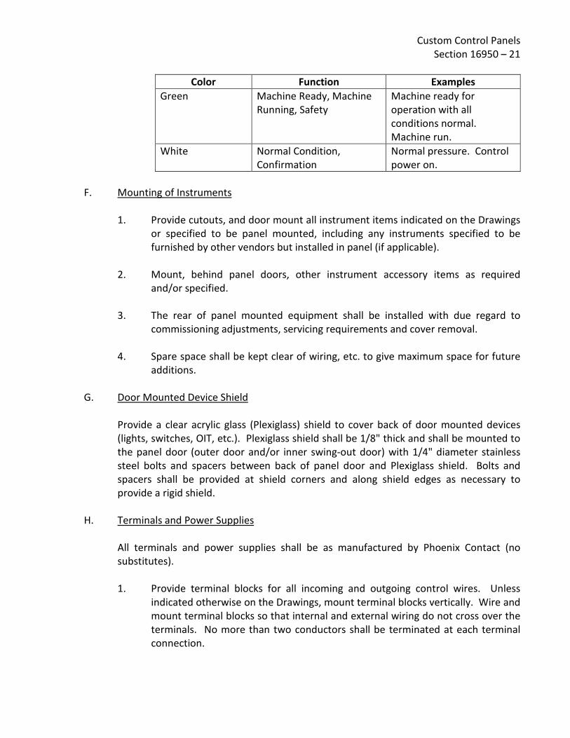
Custom Control Panels Section 16950 – 21
Color Function Examples
Green Machine Ready, Machine Running, Safety
Machine ready for operation with all conditions normal. Machine run.
White Normal Condition, Confirmation
Normal pressure. Control power on.
F. Mounting of Instruments
1. Provide cutouts, and door mount all instrument items indicated on the Drawings
or specified to be panel mounted, including any instruments specified to be furnished by other vendors but installed in panel (if applicable).
2. Mount, behind panel doors, other instrument accessory items as required and/or specified.
3. The rear of panel mounted equipment shall be installed with due regard to commissioning adjustments, servicing requirements and cover removal.
4. Spare space shall be kept clear of wiring, etc. to give maximum space for future additions.
G. Door Mounted Device Shield Provide a clear acrylic glass (Plexiglass) shield to cover back of door mounted devices (lights, switches, OIT, etc.). Plexiglass shield shall be 1/8" thick and shall be mounted to the panel door (outer door and/or inner swing-out door) with 1/4" diameter stainless steel bolts and spacers between back of panel door and Plexiglass shield. Bolts and spacers shall be provided at shield corners and along shield edges as necessary to provide a rigid shield.
H. Terminals and Power Supplies
All terminals and power supplies shall be as manufactured by Phoenix Contact (no substitutes). 1. Provide terminal blocks for all incoming and outgoing control wires. Unless
indicated otherwise on the Drawings, mount terminal blocks vertically. Wire and mount terminal blocks so that internal and external wiring do not cross over the terminals. No more than two conductors shall be terminated at each terminal connection.

Custom Control Panels Section 16950 – 22
2. Field wiring shall terminate on the "field side" of the terminal blocks. Do not connect internal panel wiring to the "field side" of the terminal blocks. Do not connect field wiring to the "panel side" of the terminal block.
3. Unless specified otherwise, all field wiring shall be connected to fused terminal
blocks, including input and output terminals to and from PLCs. PLC loop powered analog signals shall be connected to two-level, non-fused terminal blocks.
4. Terminal blocks shall be modular, rail mounted, rated at 20 amperes, 600 volts capable of terminating wire sizes 12 through 24 AWG and constructed of polyamide thermoplastic. Terminal blocks shall be UL listed in accordance with UL 486A and 1059. All current carrying parts shall be made of copper or brass electroplated with tin/lead. Terminal connection shall be a screw clamp pressure plate connection, designed such that the clamping screw does not clamp the screw directly to the wire.
5. Provide symmetrical steel assembly rails, end brackets, jumper bars, and other accessories as required for a complete terminal block assembly.
6. Terminal blocks shall be consecutively numbered from top to bottom with preprinted marking tags. Tags shall be white polyamide and hot printed with black symbols so that the print is permanent.
7. Specific model terminal blocks shall be as follows: a. Phoenix Contact Terminal Block, Single-Level, Non-Fused, Model UK5N b. Phoenix Contact Terminal Block, Two-Level, Non-Fused, Model UKKB5 c. Phoenix Contact Terminal Block, Fused, Model UKK5-HESILED d. Phoenix Contact End Cover, Model D-UKKB3/5 e. Phoenix Contact Clamp, Model E/UK1. Alternate model terminal blocks or terminal blocks from other manufacturers are not acceptable.
I. Power Supplies
Unless specified otherwise, power supply shall be Phoenix Contact Power Supply AC-DC 24V @ 2A 85-264V In, Enclosed DIN Rail Mount Mini Series, Model 2938730. Alternate model power supplies from other manufacturers are not acceptable.

Custom Control Panels Section 16950 – 23
2.06 MARKERS AND NAMEPLATES
A. Markers
Each signal, control, alarm, and indicating circuit conductor connected to a given electrical point shall be designated by a single unique number, which shall be shown on all manufacturer shop drawings. These numbers shall be marked on all conductors at every terminal. Conductor markers shall be pre-printed white identification tags with clear heat shrinkable tubing. Heat shrinking of the identification tags and clear tubing shall be in accordance with manufacturer's specifications.
1. Conductor identification tags shall be in accordance with the following
requirements:
a. The conductor identification tags shall consist of heat shrinkable flame retarded identification sleeves that fit tightly over the conductor or cable to be marked. Identification sleeves shall be made of a seamless cross-linked polyolefin with a 3 to 1 shrink ratio.
b. The conductor identification tag system shall be UL recognized to
Standard 224, MIL-M-81531. Identification tags shall be smear resistant prior to shrinking and achieve a permanent mark when shrunk, without the need for permatizing equipment. Identification marks shall be legible after 20 eraser rubs and 30 solvent brush strokes.
c. Identification sleeves shall be seamless. Sleeves shall be resistant to
common industrial fluids including Freon TF, Isopropyl Alcohol and Ethylene Glycol. Identification sleeves shall have a temperature range of -30ºC to 105ºC and a dielectric strength of 500 V/mil minute. The identification sleeves shall be suitable for indoor or outdoor use. The conductor identification tag system shall be as manufactured by Raychem/Kroy Cable Marking, or Brady-Permasleeve White Polyolefin (B-342), or equal. Heat shrinkable thermoplastic tags are not acceptable.
2. The conductor identification sleeves shall be provided with heat shrink clear
tubing in accordance with the following: a. To provide a long-term permanent marker in high ambient temperatures,
a translucent (clear) shrink tube shall be placed over each wire marker (extending past both edges of adhesive wire marker) and heat shrunk.
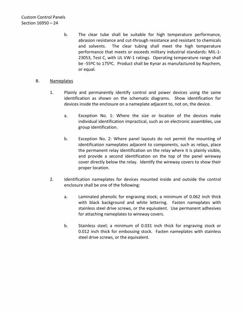
Custom Control Panels Section 16950 – 24
b. The clear tube shall be suitable for high temperature performance, abrasion resistance and cut-through resistance and resistant to chemicals and solvents. The clear tubing shall meet the high temperature performance that meets or exceeds military industrial standards: MIL-1-23053, Test C, with UL VW-1 ratings. Operating temperature range shall be -55ºC to 175ºC. Product shall be Kynar as manufactured by Raychem, or equal.
B. Nameplates
1. Plainly and permanently identify control and power devices using the same identification as shown on the schematic diagrams. Show identification for devices inside the enclosure on a nameplate adjacent to, not on, the device.
a. Exception No. 1: Where the size or location of the devices make
individual identification impractical, such as on electronic assemblies, use group identification.
b. Exception No. 2: Where panel layouts do not permit the mounting of
identification nameplates adjacent to components, such as relays, place the permanent relay identification on the relay where it is plainly visible, and provide a second identification on the top of the panel wireway cover directly below the relay. Identify the wireway covers to show their proper location.
2. Identification nameplates for devices mounted inside and outside the control
enclosure shall be one of the following:
a. Laminated phenolic for engraving stock; a minimum of 0.062 inch thick with black background and white lettering. Fasten nameplates with stainless steel drive screws, or the equivalent. Use permanent adhesives for attaching nameplates to wireway covers.
b. Stainless steel; a minimum of 0.031 inch thick for engraving stock or
0.012 inch thick for embossing stock. Fasten nameplates with stainless steel drive screws, or the equivalent.

Custom Control Panels Section 16950 – 25
2.07 WIRING METHODS
A. Panel wiring shall be neatly contained in panel wireways, including incoming and outgoing field control wiring. Provide separate wireways for internal wiring and field wiring. Panelways shall be colored white for 240 VAC circuits and colored light gray for 120 VAC, restricted slot design, with matching snap on overs. Provide panelways with mounting holes and nylon "push" rivets for mounting. Panelways material shall be PVC or noryl. Panelways shall be as manufactured by Panduit, or equal.
B. Provide minimum 2 inches of clearance between panelway and wire terminations to
allow for clear viewing of wire identification marking. C. Wiring run to control devices on the front door shall be tied together at short intervals
and secured to the inside front door with Panduit adhesive mounts. Mounts shall be Clincher adjustable releasable clamp type for wire bundles 0.69 inch in diameter or smaller, or AM2-C mounts with Uni-Ty releasable nylon cable ties for bundles larger than 0.69 inch in diameter. Mounts shall be attached to front panel with Eastman 910 adhesive, or equal.
D. Signal and Control Circuit Wiring
1. Wire type and sizing:
a. Conductor shall be flexible stranded copper machine tool wire. b. These shall be UL listed Type MTW flexible or Type SIS and shall be rated
600 volts. c. Wires for instrument signal circuits and alarm input circuits shall be No.
14 AWG, minimum.
d. Wires connecting to PLC wiring arms shall be multiconductor No. 16 AWG, minimum.
e. All other wires, including shielded cables, shall be No. 16 AWG, minimum.
Shielded cables shall be used for analog signals.
f. Wire insulation colors shall be as follows: i) Control Wiring
a) PLC Inputs (Status) DI = Blue b) PLC Outputs DO = Brown c) 12VDC Positive = Red

Custom Control Panels Section 16950 – 26
d) 12VDC Negative = Black e) 24VDC Positive = Yellow f) 24VDC Negative = Blue g) 120 VAC Positive = Red h) 120 VAC Negative = White i) 120VAC Switch Leg = Do not use Black, Red or Blue j) 480 VAC Switch Leg = Do not use Brown, Orange or
Yellow
ii) Power Wiring
a) 480 VAC A-Phase = Brown, B-Phase = Orange, C-Phase = Yellow
b) 120/208/240 VAC A-Phase = Black, B-Phase = Red, C-Phase = Blue
c) Phase tape with colors is acceptable d) Foreign Power = Yellow Note: Match existing wiring when appropriate.
2.08 SPARE PARTS
A. All spare parts shall be of the same material and workmanship, shall meet the same requirements, and shall be interchangeable with the corresponding original parts furnished. Spare parts shall be properly packaged for shipment and storage, and shall be labeled with the manufacturer's part number(s).
B. As a minimum, Contractor shall furnish the following spare parts:
1. Five (5) fuses of each type and size for single-phase power (including control
power). 2. Two (2) indicating light assemblies for each type of pilot light. 3. One (1) control relay of each type and rating. 4. One (1) time delay relay of each type and rating.
C. Where control panels operate on 3 phase power and/or are equipped with motor starting equipment and components, Contractor shall furnish the following additional spare parts:
1. Three (3) fuses of each type and size for three-phase power.

Custom Control Panels Section 16950 – 27
2. Two (2) complete sets of 3-pole stationary and moving contact assemblies for
each size AC contactor. 3. Two (2) operating coils for each size AC contactor. 4. One (1) contactor auxiliary contact of each type. 5. Three (3) contactor overload relays of each type and rating, each relay with a
complete set of contact blocks. 6. One (1) spare set of heater elements for each heater rating provided.
PART 3 - EXECUTION 3.01 FACTORY TESTS
Prior to shipment, each control panel shall be inspected and tested for correct operation by the manufacturer. Each circuit shall be tested for continuity, short circuits, and fault grounds. The functional operation of the control panel shall be tested, including operation of all input and output (I/O) points, control devices, and motor controls. Temporary connections shall be provided between control panels and other system components. Subsequent testing of the system shall include, but not be limited to, programming of the PLC and operator interfaces. PLC system shall be programmed as required. A. Initial Testing Initial testing of the control panel shall include configuration of the PLC and its
communications equipment (where PLC is provided) energizing each digital I/O and simulating each analog I/O using a loop simulator and calibrator. Circuits not energized shall be tested for continuity. Energized circuits shall be tested through all components from the terminal blocks in the control panel to the control devices and hardware I/O memory locations in the PLC. Testing of the control system shall be considered completed after control system operation has been successfully simulated at least four (4) times.
An I/O checklist shall be provided for all points in the control panel. The checklist shall
include, for each point, the tag name of the point, a description of the point, comments, date and time of the test, and a signature line for the person performing the test. Where a PLC is provided, each digital point set and reset shall be shown. Verification of all analog points shall be shown at 0%, 25%, 50%, and 100% of range. The checklist shall be submitted to District.
Custom Control Panels Section 16950 – 28
B. District-Witnessed Factory Testing District shall have the option of witnessing the functional shop test. Contractor shall
notify District at least three (3) weeks prior to the scheduled functional shop test. After completion of initial testing, the subsequent testing shall be conducted for
inspection by District. All control functions and all status and alarm monitoring and indication shall be demonstrated under simulated operating conditions. Simulating equipment shall be provided and wired into the control system for this testing. The system shall be revised, modified, and adjusted as required by District during the testing period. Testing shall continue for the time period required by District to observe and verify any revisions and shall continue to District's satisfaction. Where panel is equipped with a PLC, the PLC and HMI programs shall be loaded and fully tested in the factory. All hardware, instruments, and software shall be provided as necessary to perform the testing.
3.02 SITE TESTS
A. General
Control panel shall be tested with all field wiring connected. All adjustable set points and time delays shall be set as required. Operation of control panel and field devices shall be checked to verify correct operation. All required adjustments shall be made as required for correct operation.
B. Specific Field Verifications The following specific field verifications shall be performed:
1. Panel control circuits are grounded with one (1) terminal of each load device connected to the grounded conductor.
2. Panel signal and control wiring are separated and installed in separate wireways
with barriers between the power wiring and the signal and control wiring. 3. Panel is connected to the facility grounding system as specified. 4. Panel tops of wall-mounted panels are mounted at the same elevation (unless
noted otherwise). 5. Panel inner door contains a copy of the as-built elementary and wiring diagrams. 6. Panel inner door contains copies of all applicable equipment warranties.

Custom Control Panels Section 16950 – 29
7. Panel inner door contains a drawing holder. 8. Panel as-built shop drawings and applicable equipment warranties are enclosed
in a transparent, protective jacket. 9. All panel functions are as specified.
3.03 CONTROL PANEL MOUNTING
A. General
Control panels shall be field mounted as indicated on the Drawings or on equipment supplied as shown on District-accepted shop drawings.
B. Mounting Requirements Unless indicated otherwise on the Drawings or in the specification sections for the
packaged equipment systems, control panels shall be mounted as follows:
1. Control panels supported directly by concrete or concrete masonry walls shall be spaced apart not less than 1-5/8" by strut channel between panel and wall. Strut channel shall be attached to the wall as shown on the Drawings. Panels shall be attached to strut channel with stainless steel strut threaded studs, washers, and nuts. Unless specified others, strut stud diameter shall be 1/16” less than the panel mounting holes.
2. Panels shall be mounted to structures or support systems that are free of
vibration or shock. 3. Support systems shall not be attached to handrails, process piping, or
mechanical equipment, unless indicated on the Drawings. 4. Unless indicated otherwise on the Drawings, materials used for support of
control panels shall be constructed of Type 316 stainless steel. Support systems, including panels, shall be designed to prevent deformation greater than 1/8" under the enclosed equipment load and an external load of 200 pounds in any direction.
5. Panels shall be shimmed to precise alignment so doors operate without binding. 6. Floor-mounted cabinets shall be mounted on 3" minimum high concrete
housekeeping pads or grouted bases as indicated on the Drawings.

Custom Control Panels Section 16950 – 30
7. Terminals and terminal blocks shall be sprayed with a silicone resin, similar to Dow Corning R-4-3117 conformal coating, after all terminations and testing have been completed.
3.04 MANUFACTURER'S SERVICES
Unless specified otherwise, equipment manufacturer's services shall be provided at the job site for the minimum number of 8-hour work days listed below, travel time excluded:
A. Two (2) work days to check the installation, calibrate the equipment, supervise start-up,
and supervise testing of the system. B. One (1) work day to instruct the District's personnel in the operation and maintenance
of the equipment.
END OF SECTION

Revised 04/14/16
SPECIFICATIONS - DETAILED PROVISIONS Section 17005 - General Instrumentation and Control Components
C O N T E N T S
PART 1 - GENERAL ....................................................................................................................... 1
1.01 DESCRIPTION .............................................................................................................. 1 1.02 RELATED SECTIONS ...................................................................................................... 1 1.03 REFERENCE STANDARDS AND CODES ............................................................................ 1 1.04 INSTRUMENTATION AND CONTROL SUBCONTRACTOR .................................................. 2 1.05 PERFORMANCE SPECIFICATIONS AND DRAWINGS ......................................................... 4 1.06 INSTRUMENTATION AND CONTROL EQUIPMENT ........................................................... 4 1.07 SUBMITTALS ............................................................................................................... 5 1.08 QUALITY ASSURANCE................................................................................................. 10
PART 2 - PRODUCTS ................................................................................................................... 11 2.01 GENERAL ................................................................................................................... 11 2.02 GENERAL REQUIREMENTS FOR COMPONENTS AND APPURTENANCES .......................... 12 2.03 FLOAT SWITCHES AND INTRINSICALLY SAFE RELAYS ..................................................... 13 2.04 PRESSURE GAUGES .................................................................................................... 14 2.05 DIAPHRAGM SEALS .................................................................................................... 14 2.06 PRESSURE SWITCHES ................................................................................................. 15 2.07 DIFFERENTIAL PRESSURE SWITCHES ............................................................................ 15 2.08 PRESSURE TRANSMITTERS ......................................................................................... 16 2.09 DIFFERENTIAL PRESSURE TRANSMITTERS .................................................................... 16 2.10 ULTRASONIC LIQUID LEVEL MEASUREMENT SYSTEM ................................................... 17 2.11 SUBMERSIBLE LIQUID LEVEL MEASUREMENT SYSTEM .................................................. 19 2.12 CONDUCTANCE LIQUID LEVEL MEASUREMENT SYSTEM ............................................... 21 2.13 CONDUCTIVITY MEASUREMENT SYSTEM ..................................................................... 22 2.14 ANCILLARY MATERIALS AND COMPONENTS ................................................................ 25
PART 3 - EXECUTION .................................................................................................................. 26 3.01 GENERAL ................................................................................................................... 26 3.02 INSTALLATION ........................................................................................................... 26 3.03 FIELD QUALITY CONTROL ........................................................................................... 28 3.04 FIELD TESTING ........................................................................................................... 30 3.05 INSTRUCTION ............................................................................................................ 31


General Instrumentation & Control Components Section 17005 – 1
SECTION 17005 GENERAL INSTRUMENTATION AND CONTROL COMPONENTS
PART 1 - GENERAL 1.01 DESCRIPTION
A. Contractor shall provide all equipment, materials, and labor, and required to place into service a fully configured, integrated, and operational instrumentation and control system as indicated on the Drawings and specified herein.
B. Design, fabricate, coordinate, install, calibrate, and test the instrumentation and
control system to provide proper operation and to interface with related equipment and materials.
C. Furnish and install auxiliary and accessory devices necessary for system
operation or performance and to interface with equipment specified herein and in other Sections of these Specifications.
1.02 RELATED SECTIONS
A. The Contract Documents are a single integrated document, and as such all Specification Sections apply. It is the responsibility of the Contractor and its subcontractors to review all Sections and ensure a complete and coordinated project.
B. Related Specification Sections include, but are not limited to, the following:
1. Division 11 – Equipment 2. Division 13 – Special Construction 3. Division 15 – Mechanical 4. Division 16 – Electrical 5. Division 17 – Instrumentation and Controls
1.03 REFERENCE STANDARDS AND CODES
A. International Society of Automation (ISA)
1. ISA S5.1 – Instrumentation Symbols and Identification.

General Instrumentation & Control Components Section 17005 – 2
2. ISA S5.3 – Graphic Symbols for Distributed Control/Shared Display Instrumentation, Logic, and Computer Systems.
3. ISA S5.4 – Instrument Loop Diagrams. 4. ISA S20 – Specification Forms for Process Measurement and Control
Instruments, Primary Elements, and Control Valves. 5. ISA TR20.00.01 – Specification Forms for Process Measurement and
Control Instruments Part 1: General Considerations.
B. National Electrical Manufacturers Association (NEMA) C. National Fire Protection Agency (NFPA)
1. NFPA 70 - National Electrical Code (NEC). 2. NFPA 79 – Industrial Control Equipment.
Equipment and materials, including installation of same, shall meet or exceed the applicable requirements of the above standards and codes (latest edition).
1.04 INSTRUMENTATION AND CONTROL SUBCONTRACTOR
Contractor shall designate an Instrumentation and Control Subcontractor (ICS) to be responsible to furnish all services, equipment, and material specified herein. A. Qualifications
1. As a minimum, the ICS shall have been regularly engaged in the design, selection, purchase, fabrication, installation, calibration, startup, and testing of instrumentation and control equipment on municipal water and wastewater projects.
2. ICS shall have been regularly engaged in performing coordination, design,
and selection of equipment and controls to interface between instrumentation and control equipment, and to interface with system control panels, motor control centers, variable frequency drives, packaged systems, programmable logic controllers, etc. for municipal water and wastewater projects of similar or larger magnitude for at least 5 years.
3. Contractor shall submit ICS qualifications and project references (5
minimum) for District review and approval.

General Instrumentation & Control Components Section 17005 – 3
4. Personnel employed for system engineering, coordination, supervision, installation, startup, operational testing, and training shall be regularly employed and trained by the ICS.
B. Responsibilities
1. Design, select, fabricate, coordinate, calibrate, and test the
instrumentation and control system to provide proper operation and to interface with related equipment and materials furnished by other suppliers under other Sections of these Specifications, with existing facilities (where required), and with District provided Remote Telemetry Unit (RTU) equipment and/or Supervisory Control and Data Acquisition (SCADA) system equipment.
2. Coordinate the design, selection, and fabrication of instrumentation and
control systems furnished by others, and confirm that the proposed equipment will provide the required monitoring/control and shall properly interface with other equipment systems (new and existing).
3. Design and prepare control and interconnect diagrams (loop drawings)
for all field devices, local control panels, main control panels, motor control centers, etc. showing wiring interconnections for all project equipment, instrumentation, and controls (including existing equipment, instrumentation, and controls).
4. Review and approve shop drawings prepared by the motor control
center, variable frequency drive, and other electrical equipment suppliers. ICS shall date and sign said shop drawings prior to submittal to the District for review.
5. Coordinate work so that all components of the instrumentation system,
including primary measuring, indicating, transmitting, receiving, recording, totalizing, controlling, alarming devices, and all appurtenances are selected, designed, and calibrated to provide the specified accuracy and performance, and are completely compatible and shall function as specified.

General Instrumentation & Control Components Section 17005 – 4
6. Provide auxiliary and accessory devices necessary for system operation or performance and to interface with equipment provided by other suppliers under other Sections of these Specifications, with existing facilities (where required), and District provided RTU equipment and/or SCADA system equipment. These devices include, but are not limited to, current isolators, signal conditioners, transducers, and interposing relays. These devices shall be provided whether they are shown on the Drawings or not, and shall be at no additional cost to the District.
7. Installation of instrumentation and control equipment and materials
need not be performed by the ICS; however, the ICS shall provide onsite technical supervision of the installation.
8. Prior to installation of any conduit associated with instrumentation and
controls, the ICS shall verify conduit size and conduit runs with the Electrical Subcontractor and equipment suppliers for specific equipment to be furnished, and notify the District of any conflicts or deviations.
9. Coordinate services of manufacturer's engineering representatives for
instrumentation and control equipment during installation, startup, operation, and instruction of District personnel.
Contactor shall subcontract the work specified herein to a qualified ICS. All work performed is the responsibility of the Contractor even though references are made herein to work requirements and responsibilities of the ICS and Electrical Subcontractor.
1.05 PERFORMANCE SPECIFICATIONS AND DRAWINGS
Instrumentation and control systems shall be furnished and installed to provide equipment performance, operation control, and/or monitoring functions as specified on the Drawings, in specific equipment sections of these Specifications, or in the Special Conditions. Control schematic diagrams, where provided on the Drawings, show control wiring and control functions for specific equipment. ICS shall prepare, or coordinate preparation of all wiring and control diagrams, and computer programs. ICS shall furnish and install all instrumentation and control components required to provide said specified performance and operation.
1.06 INSTRUMENTATION AND CONTROL EQUIPMENT
Instrumentation and control equipment shall be as specified herein, per individual equipment sections of these Specifications, and as shown on the Drawings. Not all products specified herein are necessarily required for this project.

General Instrumentation & Control Components Section 17005 – 5
1.07 SUBMITTALS
All submittals shall be in accordance with the General Conditions and requirements specified herein.
A. Shop Drawings
Contractor shall prepare and submit complete and organized information, drawings, and technical data for all equipment and components. All drawings shall be legible and reduced to a maximum size of 11” x 17” for inclusion within the submittal. Shop drawings shall include, but not be limited to, the following: 1. Detailed Bill of Materials for all instrumentation and control equipment,
and appurtenances, listing: manufacturer's name, quantity, description, size, range, and catalog/part number.
2. Summary data sheets for all instrumentation and control equipment in
accordance with ISA-20.00.01 format. As a minimum, data sheets shall include the following information: Plant equipment name/number and ISA tag number shown on the Drawings (where provided); item name as specified herein, or separate Specification sections, or indicated on the Drawings; manufacturer’s complete model number, item location; input/output characteristics; range, size, and gradation in engineering units; materials of construction for wetted parts and enclosure; and enclosure NEMA classification.
3. Complete documentation for all instrumentation and control equipment,
including: manufacturer's product literature, specifications, performance capabilities, features and accessories, materials of construction, illustrations, and data in sufficient detail to demonstrate compliance with Specification requirements. Manufacturer’s literature and data shall be marked to clearly delineate all applicable information and crossing out all inapplicable information.
4. Engineering selection and design parameters and calculations for
instrumentation and control components including range, material compatibility for process medium, temperature ratings for project ambient conditions, temperature error and proposed mitigation for same, and other pertinent selection and sizing criteria.
5. Manufacturer’s data and drawings showing dimensions, physical
configurations, methods of connecting instruments and control equipment together, installation and mounting details, single instrument loop diagrams, and wiring schematics.

General Instrumentation & Control Components Section 17005 – 6
6. Product data sheets for instrument cables and controller/transmitter cables. Installation requirements for cables and conductors, including shielding, splicing, and grounding requirements.
7. Control program for programmable controllers (if applicable) with
complete listing and description of all program functions, all input and output parameters, and factory settings.
8. Interface between instruments, controllers, motor starters, control
panels, variable frequency drives, PLCs, etc., District furnished equipment (when supplied), and other equipment related to the instrumentation and control system.
9. Control ladder diagrams for all control, protection and monitoring
circuits, including control panel wiring. Ladder diagrams shall show all switches, push buttons, relays, timers, etc. Show all interconnections between power sources and device elements of a particular system or equipment, and all interlocks with other equipment/systems in a manner that fully indicates the circuit function and operation.
10. Loop diagrams for each monitoring and/or control loop. The loop
diagrams shall show all components of the loop: analog, digital, and discrete including all relays, switches, signal isolators, etc. which are being provided for proper operation. Loop diagrams shall be provided for all analog and control system components, including those components specified in other Sections of these Specifications and/or shown on the Drawings. Loop diagrams shall be prepared according to ISA-S5.4 format, and shall also include the following:
a. All interconnecting wiring between equipment, panels, terminal
junction boxes, and field mounted components. Show all panel terminal board identification numbers and all wire numbers. Show all intermediate terminations between field elements and panels.
b. The location of all devices. c. The instrument description, including type, manufacturer, model
number, range, set points, and operation (e.g. fail open, open on energization, normally closed, etc.) as applicable.
d. The instrument loop power requirements back to the termination
on the terminal block, fuse block (including fuse size), etc., as applicable.

General Instrumentation & Control Components Section 17005 – 7
e. All grounding points within cabinets and panels and identify the connection point of individual components.
f. Each diagram shall include a table summary with output capability
of the transmitting instrument, input impedance of each receiving instrument, estimate of loop wiring impedance based on wire size and approximate length, total loop impedance, and reserve output capacity.
11. Interconnection diagrams for all field devices, local control panels, main
control panels, motor control centers, etc. showing wiring interconnections for all project equipment, instrumentation, and controls (including existing equipment, instrumentation, and controls). Interconnection diagrams shall be provided for all equipment and appurtenances, including equipment specified in other Sections of these Specifications and/or shown on the Drawings. Interconnection diagrams shall be point-to-point type and shall show all conduit and wiring interconnections with electric panel and circuit numbers for all power sources.
12. Proposed nameplate descriptions for all instrumentation and control
equipment.
B. Field Testing and Demonstration Plan
Contractor shall prepare and submit for approval a written plan for field testing and demonstrating that each instrumentation and control system meets the specified operational and performance requirements. Submit a written plan with step by step procedures to be used during pre-startup, startup, and final demonstration testing of system operation and performance.
C. Operation and Maintenance Manual
Contractor shall submit a detailed Operation and Maintenance (O&M) Manual for all instrumentation and control equipment specified herein and incorporated into the Work. The O&M Manual shall be provided in accordance with the requirements of the District's General Conditions, Section 01430, and as specified herein.

General Instrumentation & Control Components Section 17005 – 8
The O&M Manual shall include, but not be limited to, the following: 1. Equipment Performance Data and Drawings
a. Detailed Bill of Materials for all instrumentation and control equipment, and appurtenances, listing: manufacturer's name, quantity, description, size, range, and model/part number.
b. Manufacturer's product literature, specifications, performance
capabilities, features and accessories, materials of construction, and illustrations.
c. Manufacturer’s data and drawings showing dimensions, physical
configurations, installation and mounting details, single instrument loop diagrams, and wiring schematics.
d. Control diagrams, loop diagrams, and interconnect diagrams for
all field devices, local control panels, main control panels, motor control centers, etc. for all project equipment, instrumentation, and controls (including existing equipment, instrumentation, and controls).
2. Equipment Installation Requirements
a. Complete, detailed installation instructions for all instrumentation and control equipment, and appurtenances.
3. Equipment Operation Data
a. Complete and detailed instructions for adjusting all equipment settings, including: input power, output signal, range, span, sensitivity, etc.
b. Complete and detailed user manuals and operating instructions,
including operator interface menus, programming, and setup parameters for all controllers.
c. Printed list of all final setup parameters for each controller,
including factory settings and any field modifications to factory settings.

General Instrumentation & Control Components Section 17005 – 9
4. Equipment Service and Maintenance Data
a. Maintenance data shall include all information and instructions required by District's personnel to keep equipment adjusted and calibrated so that it functions properly under the full range of operating conditions.
b. Explanation with illustrations as necessary for each maintenance
task. c. Recommended schedule of maintenance tasks. d. Troubleshooting instructions. e. List of maintenance tools and equipment. f. Recommended spare parts list. g. Names, addresses and phone numbers of all manufacturers and
manufacturer's local service representatives. 5. Manufacturer Warranties
D. Final O&M Manual Upon successful completion of startup and initial operation, Contractor shall submit a Final O&M Manual in accordance with the requirements of the District’s General Conditions, Specification Section 01430, and as specified herein. 1. As-built drawings (including all field changes) for all wiring and
interconnection diagrams shall be incorporated into the Final O&M Manuals.
2. In addition, pre-startup and post-startup written certification reports as
specified herein shall be included in the Final O&M Manual.

General Instrumentation & Control Components Section 17005 – 10 1.08 QUALITY ASSURANCE
A. Manufacturers
To facilitate the District’s future operation and maintenance, furnish equipment which is the product of one manufacturer to the maximum extent possible. Where this in not practical, all equipment of a given type shall be the product of one manufacturer. All equipment shall be of the manufacturer’s latest design and shall produce or be activated by signals which are standards for the water and wastewater industry.
B. Model Numbers
Model numbers supplied herein are provided for information purposes only, to assist Contractor in selecting equipment that conforms to the Specification and Drawing requirements. In case of any conflict between model numbers provided and the descriptive requirements specified herein, the descriptive requirements shall govern.
C. Standard of Quality
Only equipment of the types and sizes specified which has been demonstrated to operate successfully shall be furnished. All material and equipment furnished shall be listed by and shall bear the label of Underwriters Laboratories (UL), Edison Testing Labs (ETL), or Factory Mutual (FM).
D. Instrumentation and Control Subcontractor's Certifications Prior to startup and initial operation of all instrumentation and control equipment (including existing instrumentation and control equipment), the ICS shall submit a written report stating that equipment has been coordinated, calibrated, properly installed, and is ready for startup. After startup and when equipment is ready to be operated, the ICS shall submit a written report for the instrumentation and control equipment certifying that the equipment is ready to be operated, is safe to operate and has been checked, inspected, calibrated, and adjusted as necessary; has been operated under varying service conditions and operated satisfactorily; and is fully covered under the terms of the guarantee.

General Instrumentation & Control Components Section 17005 – 11
PART 2 - PRODUCTS 2.01 GENERAL
A. Where indicated on the Drawings, specified by the individual equipment sections in these Specifications, or by the Special Conditions, the instrumentation and control components shall be as specified herein.
B. Unless specified otherwise, all equipment shall be suitable for operation over an
ambient temperature range of 15°F to 122°F, and at a maximum elevation of 3,300'. Cooling or heating equipment shall be provided if required by the instrumentation and control equipment. Where dissipation of heat cannot be adequately accomplished with natural convection (NEMA 4X enclosures) or forced air ventilation (NEMA 1 gasketed enclosures), additional cooling or heating shall be furnished.
C. Unless specified otherwise, electrical enclosures for indoor equipment shall be
rated NEMA 1 gasketed, or better. Unless specified otherwise, electrical enclosures for outdoor equipment shall be rated NEMA 4X. Outdoor enclosures with sunlight exposure shall be provided with sun shields. In addition, instrumentation located in areas subject to wash down or exposure to chemicals shall be provided with NEMA 4X electrical enclosures.
D. All instrumentation in hazardous areas shall be intrinsically safe and shall be
approved for use in the particular hazardous (classified) location in which it is to be installed.
E. All panel mounted instruments shall have matching style and general
appearance. Instruments performing similar functions shall be of the same type, model, or class, and shall be of one manufacturer.
F. Analog measurements and control signals shall be as indicated herein, and shall
vary in direct linear proportion to the measured variable, except as noted. Unless specified otherwise, analog output signals shall be 4 to 20 milliamperes (ma) DC.
G. Unless specified otherwise, power for the instrument and control equipment
shall be 120VAC, single phase, 60 Hz. H. Where DC power supplies are not furnished integral with any one instrument
system loop, Contractor shall provide a separate solid-state power supply and fuses (primary and secondary).

General Instrumentation & Control Components Section 17005 – 12 2.02 GENERAL REQUIREMENTS FOR COMPONENTS AND APPURTENANCES
A. Materials and Components
Electrical materials and components shall be as specified in Section 16050, as indicated on the Drawings, and as specified herein.
B. Signal Isolators, Converters, and Power Supplies
Signal isolators shall be furnished and installed in each measurement and control loop, wherever required to ensure adjacent component impedance match, or where feedback paths may be generated. Signal converters shall be included where required to resolve any signal level incompatibilities. Signal power supplies shall be included, as required by the manufacturer's instrument load characteristics, to ensure sufficient power to each loop component.
C. Tags and Nameplates
1. Each field instrument shall be provided with a rectangular Type 316 stainless steel tag. The tag shall be engraved with the project instrument tag number. The instrument tag shall be attached directly to the instrument with stainless steel screws or with a stainless steel chain.
2. Each panel mounted instrument, controller, or control component shall
be provided with a nameplate. The nameplate shall be engraved with the project description of the device. Nameplates shall conform to the requirements of Section 16050.
D. Wiring and Cables
1. Wire Type and Sizes
All power and control wiring shall be provided in accordance with Section 16050. Instrument supply power conductors shall be minimum #12 AWG. Control signal conductors shall be minimum #14 AWG. Wire insulation colors shall be in accordance with Section 16050.

General Instrumentation & Control Components Section 17005 – 13
2. Cables
Shielded cables shall be minimum #16 AWG and shall be in accordance with Section 16050. Instrument transducers or sensors requiring special cable shall be provided by the instrument manufacturer and shall be factory connected to the device. Cable between the transducer or senor and corresponding controller shall be provided with the device. ICS shall verify the length of cable required for each specific installation location. Cable shall be installed in a single run with no splices.
3. Wire Termination Conductors from field instruments or components shall terminate in
control panels, MCC sections, etc. at terminal blocks. 4. Wire Marking
All conductors and cables shall be marked at termination points with a marking system as specified in Section 16050.
2.03 FLOAT SWITCHES AND INTRINSICALLY SAFE RELAYS
A. Float switches shall be designed for operation in water and raw sewage and shall
be hermetically sealed in high impact corrosion resistant polypropylene or polyurethane. Cable shall be minimum 16 gauge multi-strand polyvinylchloride (PVC) jacketed cable (oil and water resistant) suitable for underwater use and heavy flexing service. Float switches shall be rated minimum 4 A at 120 VAC. Each float switch shall be utilized for one operation. A single float switch shall not be used as example for pump start and stop.
B. Float switches shall be as manufactured by Flygt Corporation, Warrick Controls,
Anchor Scientific Inc., Consolidated Electric Co., or equal. C. Unless specified otherwise, each float switch shall be provided with an
intrinsically safe relay complete with reduced voltage transformer and contacts. Intrinsically safe relays shall be specified for use in NEC, Class I, Division 1 (hazardous) locations, and shall be Factory Mutual or UL listed for explosion proof service. Intrinsically safe relays shall be as manufactured by Warrick (no substitutes).

General Instrumentation & Control Components Section 17005 – 14 2.04 PRESSURE GAUGES
A. Unless otherwise shown or specified, pressure gauges shall be weatherproof and provided with 4-1/2" dials, 1/4" or 1/2" threaded connections, and black phenolic resin, black Pocan, or epoxy coated aluminum cases with safety glass windows. Gauge socket and internal component materials shall be compatible with the process medium. As a minimum, gauge sockets and internal components (including bourdon tubes and tips, bellows, or diaphragms) shall be constructed of Type 316L stainless steel. Gauges shall be suitable for dry or liquid filled operation. Gauge accuracy shall be ±0.5% of span per ASTM B40.1, Grade 2A. Gauge range shall be selected for 150% of the working pressure or vacuum of the monitored medium. Gauge dials shall be provided with white backgrounds and black markings. Gauge units shall be applicable to the medium and pressure and/or vacuum range.
B. Pressure gauges shall be as manufactured by Ashcroft, Wika, Marsh Instruments,
or equal. 2.05 DIAPHRAGM SEALS
A. General
Where shown on the Drawings or specified elsewhere, diaphragm seals shall be provided between the process medium and the pressure or vacuum sensing element (e.g. gauge, transmitter, or switch). Diaphragm seals shall be provided with upper and lower housings and diaphragms that are welded or clamped between the housings. Upper and lower housings shall be connected with bolts (4 minimum). Diaphragm seals shall be provided with 1/2" threaded female NPT process connections, 1/4" or 1/2" threaded instrument connections, and lower housings with 1/4" flushing connections. Unless otherwise shown on the Drawings, one (1) diaphragm seal shall be provided for each instrument for direct mounting. Manufacturer shall be responsible for selecting the diaphragm seal based on each specific instrument assembly, including the diaphragm size, diaphragm material, diaphragm spring constant, assembly fill fluid medium, assembly fill fluid volume, and connection piping size (if not direct mounted) to maintain a minimum accuracy of ± 1% of full instrument range based on an ambient temperature range of 20°F to 120°F and exposure to direct sunlight. In addition, manufacturer shall be responsible for selecting diaphragm, bottom housing, and

General Instrumentation & Control Components Section 17005 – 15
gasket materials to be compatible with the process medium. As a minimum, diaphragm, lower housing, upper housing, and bolts shall be constructed of Type 316L stainless steel. Diaphragm seals shall be as manufactured by Ashcroft, Wika, or equal.
B. Water Service (Potable and Non-Potable) Diaphragms seals for water service shall be of all Type 316L stainless steel construction, including diaphragm, lower housing, upper housing, and hardware.
C. Chlorine Service (Solution) Diaphragms seals for chlorine service shall be of all Hastelloy C-276 construction, including diaphragm, lower housing, upper housing, and hardware.
2.06 PRESSURE SWITCHES
A. Pressure switches shall utilize bourdon tubes, diaphragms, or bellows as the sensing/actuating element. Unless otherwise specified, the sensing/actuating element material shall be Type 316 stainless steel. The set point shall be readily field adjustable over the range specified. Switches shall have deadband adjustable up to a maximum of 100% of switch range. Pressure range shall be as indicated on the Drawings. Switches shall be SPDT, rated for 5 A at 240 VAC. Unless specified otherwise, switch enclosures shall be rated NEMA 4X. Switch pressure connection shall be 1/4" FNPT.
B. Pressure switches shall be Model 836 as manufactured by Allen Bradley (no
substitutes). 2.07 DIFFERENTIAL PRESSURE SWITCHES
A. Differential pressure switches shall utilize bourdon tubes, diaphragms, or bellows as the sensing/actuating element. Unless otherwise specified, the sensing/actuating element material shall be stainless steel. The set point shall be readily field adjustable over the range specified. Switches shall have deadband adjustable up to a minimum of 50% of switch range. Repeatability shall be ±1% of range. Switch pressure range shall be as indicated on the Drawings. Switches shall be SPDT, rated for 10 A (minimum) at 240 VAC. Unless specified otherwise, switch enclosures shall be rated NEMA 4X. Switch pressure connections shall be 1/4" FNPT.
B. Differential pressure switches shall be as manufactured by Winters, Ashcroft, or
equal.
General Instrumentation & Control Components Section 17005 – 16 2.08 PRESSURE TRANSMITTERS
A. Pressure transmitters shall be electronic two wire devices with the following features: adjustable span, zero and damping adjustments, integral indicator scaled in engineering units, solid state circuitry and 4-20 mA output. Accuracy shall be ±0.25% of span. Overrange capacity, without affecting calibration, shall not be less than 150% of maximum range. Process wetted materials shall be compatible with the process fluid, unless specified for installation with a diaphragm seal. Unless specified otherwise, process wetted materials shall be Type 316 stainless steel. Body material shall be Type 316 stainless steel. Transmitter process connection shall be 1/2" NPT. Fill fluid, unless otherwise specified, shall be silicone oil. Transmitter housing shall be epoxy coated low copper aluminum alloy and rated NEMA 4X, unless specified otherwise.
B. Unless specified for direct mounting, pressure transmitters shall be provided
with mounting brackets and installation kits. Bracket shall be suitable for surface mounting, pipe mounting, or block and bleed valve manifold mounting. Mounting bracket wetted materials shall be shall be compatible with the process fluid, unless specified for installation with a diaphragm seal. Unless specified otherwise, mounting bracket wetted materials shall be constructed of Type 316 stainless steel. Mounting brackets, installation kits, and accessories shall be provided by the pressure transmitter manufacturer.
C. Pressure transmitters shall be as manufactured by Foxboro (no substitutes).
2.09 DIFFERENTIAL PRESSURE TRANSMITTERS
A. Differential pressure transmitters shall be electronic two wire devices with the following features: adjustable span, zero and damping adjustments, integral indicator scaled in engineering units, solid state circuitry and 4-20 mA output. Accuracy shall be ±0.25% of span. Over-range capacity, without affecting calibration, shall not be less than 150% of maximum range. Span shall be field adjustable over at least a 4 to 1 range. Process wetted materials shall be Type 316 stainless steel. Body material shall be Type 316 stainless steel. Process connections shall be 1/2" NPT. Fill fluid, unless otherwise specified, shall be silicone oil. Transmitter housing shall be epoxy coated low copper aluminum alloy and rated NEMA 4X, unless specified otherwise. A three (3) valve manifold shall be provided with the transmitter, unless indicated otherwise on the Drawings. Manifold wetted materials shall be Type 316 stainless steel.

General Instrumentation & Control Components Section 17005 – 17
B. Differential pressure transmitters shall be provided with mounting brackets and installation kits. Bracket shall be suitable for surface mounting, pipe mounting, or block and bleed valve manifold mounting. Mounting bracket wetted materials shall be shall be compatible with the process fluid, unless specified for installation with a diaphragm seal. Unless specified otherwise, mounting bracket wetted materials shall be constructed of Type 316 stainless steel. Mounting brackets, installation kits, and accessories shall be provided by the differential pressure transmitter manufacturer.
C. Pressure transmitters shall be as manufactured by Foxboro (no substitutes).
2.10 ULTRASONIC LIQUID LEVEL MEASUREMENT SYSTEM
A. General Ultrasonic liquid level measurement systems shall consist of a microprocessor
based electronic controller, a non-contacting transducer, and cable from transducer to controller. The electronic controller shall be capable of receiving, processing, and transmitting ultrasonic signals. All operating parameters shall be entered via the controller keypad. For liquid level, the controller shall, upon demand, display current head, temperature, and distance from transducer to liquid level.
The ultrasonic liquid level measurement system shall be Miltronics Multi Ranger
Plus as manufactured by Siemens (no substitutes). B. Service The transducer shall be capable of submergence without degradation.
Transducer shall function over an ambient temperature range of -40°F to 200°F, and shall be rated by FM and CSA for Class I and II hazardous environments. Controller shall function over an ambient temperature range of 15°F to 122°F.
C. Performance The transducer shall transmit and receive an acoustic signal to accurately
measure liquid level over a range of 0' to 30', unless specified otherwise. Point of zero reference shall be operator adjustable. The output signal shall be proportional to level from 0 to 100% with a resolution of ±0.1%. The transducer shall be provided with integral temperature sensor for speed-of-sound compensation. Unless specified otherwise, the transducer shall be the Echomax XPS Series with a 6° beam angle.

General Instrumentation & Control Components Section 17005 – 18 D. Level Measurement Features 1. Controller shall be provided with output indicating meter with four
character LCD display programmable in engineering units of: feet, inches, or percent of span.
2. Interconnecting Cable: Cable between transducer and controller shall be
supplied with unit, and shall be suitable for a maximum system length of 1,000'. Contractor shall verify length of cable required for each specific installation. Cable shall be installed in a single run with no splices.
3. Discrete Outputs: Controller shall provide up to five discrete outputs,
each adjustable over entire scale range. 4. Alarms: Alarms shall be programmable for level, rate of change of level,
differential level, or loss of echo. 5. Alarm Messages: Loss of echo and cable circuit open or shorted. E. Controller Interface 1. Controller Output: 4-20 mA DC output, current isolated, into a maximum
of 600 ohms (return to ground). 2. Power Supply: Unit shall operate on 120-Volt, 60 Hz power, unless
specified otherwise. 3. Discrete Outputs: Form "C" SPDT relays, 5 amps (continuous),
non-inductive, 250 VAC. 4. Controller shall be provided with necessary output functions and
communication interfaces to enable implementation of control and monitoring operations as specified in other equipment sections of these Specifications, and/or shown on the Drawings.
F. Controller Enclosure
1. Controller enclosure shall be rated NEMA 4. 2. Indoor controllers shall be wall mounted or panel mounted. Where
controller is specified to be panel mounted, it shall be flush mounted in the panel door. ICS shall provide all brackets, supports, bezels, etc. necessary for flush panel mounting.

General Instrumentation & Control Components Section 17005 – 19
3. Outdoor controllers shall be provided with stainless steel, sheet metal sun shields (20 gauge, minimum). Sun shields shall be open at the front and bottom, and shall be of sufficient size to allow access to controller for operation and maintenance. Free edges shall be rolled. Sun shields shall be constructed without sharp edges and corners.
2.11 SUBMERSIBLE LIQUID LEVEL MEASUREMENT SYSTEM
A. General
The submersible liquid level measurement system shall continuously monitor the liquid level in a groundwater well, tank, or wet well. The measurement system shall be of the submersible level pressure type. As a minimum, the measurement system shall consist of a submersible pressure sensor, cable, and accessories, as specified herein. Unless indicated otherwise on the Drawings, the system power supply and display unit shall be the RTU or MCP identified to receive the analog level signal. The power supply shall be 24 VDC normal (9 to 28 VDC operation range). The submersible liquid level measurement system shall be Model PTX 1830 as manufactured by Druck, Inc. (GE Sensing).
B. Sensor and Cable
1. The sensor shall be an all-titanium device that accurately measures depth or level in a well, tank, or body of fluid. A micro-machined silicon measuring element shall be sealed within a titanium pressure module assembly and shall be fully isolated from the pressure media. The pressure module assembly shall be contained in a slimline, welded titanium body and terminated with an injection molded cable assembly.
2. The molded cable shall be a two-conductor cable with aluminum-mylar
shield, Kevlar strain cord, nylon vent tube, and polyurethane jacket. The integral cable vent tube shall reference the sensor to atmospheric pressure. The molded polyurethane cable along with the internal potting in the sensor transmitter shall be constructed to prevent the ingress of water into the cable and back of the sensor transmitter for indefinite immersion in a pressure of 1,000 psi.
3. The cable jacket material shall be impervious to water and chemicals
normally found in groundwater, surface water, and wastewater.

General Instrumentation & Control Components Section 17005 – 20
4. Cable lengths shall be available in 1 ft. increments up to a maximum of 1,600 ft. ICS shall determine the required cable length for each specific installation location.
5. The sensor transmitter shall be a 4-20 mA, two-wire, loop powered
device. The sensor accuracy shall be ±0.1% of full scale. Long term stability shall be ±0.1% of full scale per year. The sensor shall be suitable for operating temperatures ranging from -4 to 140°F, and sensor output shall be temperature compensated from 30 to 86°F.
6. The sensor operating pressure range shall be as indicated on the
Drawings, or specified in the Special Conditions. The sensor shall be capable of being over-pressurized to 400% of the operating full scale pressure (to a maximum of 2,000 psig) with negligible effect on calibration.
7. The sensor shall be rated by FM for use in NEC Class I, Division 1, Groups
A through D hazardous environments.
C. Accessories
Unless specified otherwise, each submersible liquid level measurement system shall be provided with the following accessories:
1. A sensor termination enclosure with the following components:
a. DIN rail mounted terminal blocks for termination of sensor cable conductors and conductors from 4-20 ma shielded cable to signal termination point.
b. Gore-Tex micro-filter designed to prevent the ingress of water
into the enclosure. c. Desiccant module with sight gage for determining desiccant
change intervals. d. PVC base and clear polycarbonate cover. Enclosure shall be rated
NEMA 4X. e. 2-inch pipe mounting kit.
2. A cable clamp designed to hold cable by distributing the clamping force
over an 8-inch long section of cable jacket.

General Instrumentation & Control Components Section 17005 – 21
3. A sensor slimline sink weight. 4. A direct calibration adaptor. 5. Spare desiccant modules (5 total) in sealed containers.
D. Lightning Surge Arrestor
Where Drawings show installation of a submersible sensor in a surface water location, the sensor shall be provided with an integral lightning surge arrestor assembly certified to IEC Standard 61000-4-5 (Level 4). Contractor shall provide a separate ground rod assembly for the surge arrestor. The resistance of the ground rod assembly shall be less than 100 ohms. A minimum #12 AWG ground conductor shall be provided from the lightning arrestor to the ground rod and shall interconnect with the drain-wire on the sensor cable.
E. Intrinsically Safe Barriers
Where Drawings show installation of a submersible sensor in a wastewater location classified as hazardous by the NEC, the sensor shall be provided with the appropriate intrinsically safe barriers.
2.12 CONDUCTANCE LIQUID LEVEL MEASUREMENT SYSTEM
A. General Each conductance liquid level measurement system shall consist of level sensors, connection fitting, and relays as shown on the Drawings and specified herein. Contractor shall furnish and install all material and appurtenances as necessary to provide a complete liquid level measurement system. Conductance liquid level measurement system shall be as manufactured by Warrick Controls Inc., Gems Sensors Inc., or equal.
B. Level Sensors Level sensors shall be conductance type, utilizing electrodes and the conductivity of the process fluid itself to measure level. The system shall be equipped with multiple level sensing electrodes and one ground electrode. The number and lengths of level sensing electrodes shall be as shown on the Drawings. Unless specified otherwise, the electrodes shall be constructed of Type 316 stainless steel and shall be provided with PVC heat shrink sheathings.

General Instrumentation & Control Components Section 17005 – 22
C. Connection Fitting Each connection fitting shall be pressure-tight, and suitable for connection to the flanged top outlet of a pressure vessel. Connection fitting shall be provided with an integral epoxy coated aluminum terminal housing and Type 316 stainless steel electrode couplings. The number of electrode couplings shall accommodate the number of level-sensing electrodes shown on the Drawings and required grounding electrode. Connection fitting flange shall be rated for a pressure that is equal to or greater than the pressure vessel rating. As a minimum, the connection fitting flange shall be rated for a working pressure of 230 psig at 100°F. The connection fitting flange shall be constructed of Type 316 stainless steel or 1018 carbon steel. Contractor shall coordinate the size of the pressure vessel top outlet flange with the connection fitting flange provided by the level measurement system manufacturer.
D. Relays Liquid level measurement system relays shall be solid-state, plug-in modules suitable for 11-pin octal sockets. Relays shall be general purpose, single level or differential service, with DPDT dry contacts rated for 5A (minimum) at 120 VAC. Relays shall be suitable for operation on 120 VAC primary voltage with 12 VAC secondary voltage.
2.13 CONDUCTIVITY MEASUREMENT SYSTEM
A. General
The conductivity measurement system shall continuously measure conductivity in aqueous solutions. The measurement system shall be sense, transmit and display/control liquid conductance, expressed in microSiemens/centimeter (mS/cm). Conductivity measurement system shall include: sensor, sensor mounting assembly, controller, junction box, interconnecting cables, cable plugs, and all appurtenances necessary to provide a complete and operable measurement system. Sensor material and mounting assembly material shall be compatible with measured liquid. The ICS shall confirm material compatibility with the measured liquid and shall confirm the pressure and temperature ratings of all components with the maximum operating conditions. Conductivity measurement system shall be the Hach 3700-SC Electrodeless Conductivity System as manufactured by Hach Company (no substitutes).

General Instrumentation & Control Components Section 17005 – 23
B. Conductivity Sensor
Conductivity sensor shall be inductive electrodeless type. The conductivity sensor shall have a built-in Pt 1000 RTD temperature compensator. The sensor shall be water resistant. Sensor wetted materials shall be available in polypropylene, PVDF, PEEK, or PFA Teflon. Unless specified otherwise, sensor wetted materials shall be PFA Teflon. The sensor shall be rated for a maximum pressure of 200 psi and a maximum temperature of 200°C. The sensor shall be equipped with an integral 5 conductor cable. Unless specified otherwise, the cable shall be provided with a Teflon coated jacket rated for 200°C.
C. Sensor Mounting Assembly
Sensor shall be convertible style with 3/4-inch NPT end connection suitable for immersion mounting, union mounting, or insertion mounting, as indicated on the Drawings and as specified below: 1. Immersion mounting – sensor shall be directly fastened on the end of a
CPVC pipe (1/2-inch diameter by 4-foot long) with 1/2 x 3/4-inch NPT coupling and plastic pipe-mount junction box with terminal strip.
2. Union mounting – sensor shall be fastened to a union adapter for
mounting into a standard 2-inch NPT pipe tee. Unless specified otherwise, union and pipe tee shall be construction of Type 316 stainless steel and shall be rated for a maximum pressure of 200 psi and a maximum temperature of 60°C.
3. Insertion mounting – sensor shall be fastened into a 2-inch ball valve
assembly for mounting into a standard 2-inch NPT pipe tee. Unless specified otherwise, ball valve assembly and pipe tee shall be construction of Type 316 stainless steel and shall be rated for a maximum pressure of 80 psi and a maximum temperature of 95°C.
Mounting assembly hardware shall be provided by the sensor manufacturer.
D. Controller
1. The conductivity controller shall be a programmable microprocessor based electronic device with full input/output signal isolation. The controller shall be correctly matched to the conductivity sensor. Unless specified otherwise, controller shall be configured to operate two (2) digital sensor inputs.
2. Controller display shall be graphic dot matrix LCD with LED backlighting.

General Instrumentation & Control Components Section 17005 – 24
3. The controller shall be provided with the following features: two (2) conductivity analog output signals (4-20 mA) capable of transmission into a maximum impedance of 500 ohms; four (4) user configurable SPDT relays (Form C) rated 5A to 230 VAC and 30 VDC resistive maximum; and 25W sensor/network card with Modbus RS232/RS485 network connection.
4. Conductivity measurement range shall be 0.5 to 10,000 mS/cm, 0 to
99.99 % concentration, and 0 to 9999 ppm total dissolved solids. Repeatability shall be ±2% of full span. Operating temperature range shall be -20 to 60°C.
5. Unless specified otherwise, power supply to controller shall be 120 VAC,
60 Hz. 6. Controller enclosure shall be rated NEMA 4X, and shall be suitable for
panel or surface mounting as indicated on the Drawings. 7. Unless specified otherwise, controller shall be Hach SC200 Model
LXV404.99.00552 as manufactured by Hach Company (no substitutes). E. Accessories
Each conductivity measurement system shall be provided with all accessories and components necessary for a complete and operational system. As a minimum, each conductivity measurement system shall be provided with the following accessories: 1. Digital gateway designed to provide a digital interface between the
conductivity sensor and controller. Unless specified otherwise, each digital gateway shall be provided with a mounting clip, NEMA 4X FRP junction box with back panel (sized for housing digital gateway), and cord fittings for sensor cable and digital extension cable.
2. Digital extension cable with end connectors for connection to digital
gateway and controller. The ICS shall determine the required cable length for each specific installation location.
A digital termination box shall be provided when the distance between the digital gateway and controller exceeds 100 meters.

General Instrumentation & Control Components Section 17005 – 25
2.14 ANCILLARY MATERIALS AND COMPONENTS
A. Pipe and Fittings
Unless indicated otherwise on the Drawings, all pressure gauges, pressure switches, and pressure transmitters shall be connected to process piping with Class 150 threaded fittings, Schedule 40 pipe nipples, and isolation ball valve. Unless specified otherwise, all fittings, pipe nipples, and ball valves shall be constructed of Type 316 stainless steel.
B. Block and Bleed Valve Manifolds Where indicated on the Drawings, pressure transmitters and differential pressure transmitters shall be provided with block and bleed valve manifolds capable of isolating process sensing lines, venting to atmosphere, and connection of test equipment for instrument calibration. Block and bleed valve manifolds shall be 3-valve or 5-valve, as indicated on the Drawings. All wetted materials shall be compatible with the process fluid. Unless specified otherwise, valves shall be constructed of Type 316 stainless steel. Block and bleed valve manifolds shall be as manufactured by Foxboro, Anderson Greenwood, or equal. Unless indicated otherwise on the Drawings, block and bleed valve manifolds shall be provided with mounting kits for mounting the manifold and pressure transmitter assembly to a 2” diameter Schedule 40 hot dipped galvanized pipe stanchion.
C. Protective Coatings
All metallic enclosures, except stainless steel, shall be provided with a corrosion resistant factory coating, fusion bonded epoxy or equivalent coating system.
D. Fasteners
Unless indicated otherwise on the Drawings, equipment and appurtenances shall be securely mounted to walls and floors using Type 316 stainless steel wedge anchors or epoxy anchors for masonry and concrete structures, and Type 316 stainless steel machine bolts and lag screws for metal and wood structures (respectively).

General Instrumentation & Control Components Section 17005 – 26 PART 3 - EXECUTION 3.01 GENERAL
A. It is the general intent of these Specifications that installation of all instrumentation and control equipment; and supply and installation of all field wiring, conduit, and wiring external to the motor control centers, control panels and electrical equipment shall be performed by the Electrical Subcontractor. The ICS shall furnish all instrumentation and control equipment specified herein and supervise installation by the Electrical Subcontractor. In addition, the ICS shall coordinate design of controls within motor control center(s), control panels and electrical equipment, and ensure compatibility of design with equipment and equipment systems.
B. The ICS's attention is directed to the electrical and mechanical details of this
project. Referral to these portions of the Contract Documents shall be required in order to understand the full intent and scope of work required.
3.02 INSTALLATION
A. General
1. All instrumentation and control equipment shall be installed in accordance with the manufacturer’s written instructions, NEC standards, requirements and standards specified herein, and as shown on the Drawings.
2. Wiring between process instruments and remote mounted signal
converters/controllers shall conform to the manufacturer’s recommended cable type and procedures.
3. All instrumentation and control equipment shall be grounded per
manufacturer's requirements. Contractor shall coordinate grounding between process instruments and remote mounted signal converters/controllers, and electrical ground system to ensure compliance with the manufacturer's recommended grounding procedures.
4. Minimum process connection size for pressure gauges, switches, and
transmitters shall be 1/2" NPT. Provide threaded reducers and 1/4" diameter nipples to transition from 1/2" diameter process connection appurtenances to 1/4" device pressure connections.

General Instrumentation & Control Components Section 17005 – 27
5. Unless indicated otherwise on the Drawings, all pressure gauges, pressure switches, and pressure transmitters shall be connected to process piping with Class 150 threaded fittings, Schedule 40 pipe nipples, and isolation ball valve. Unless specified otherwise, all fittings, pipe nipples, and ball valves shall be constructed of Type 316 stainless steel.
B. Pressure Gauges
1. Pressure gauges shall be liquid filled (fill fluid as selected by
manufacturer), except where diaphragm seals are specified. 2. For diaphragm seal installations with lower housing constructed of
materials other than Type 316 stainless steel, all pipe fittings, pipe nipples, and isolation ball valves shall be constructed of the same material as the diaphragm seal lower housing.
C. Pressure Switches
1. Pressure switches shall be provided with Type 316 stainless steel pulsation dampeners, except where diaphragm seals are specified.
2. For diaphragm seal installations with lower housing constructed of
materials other than Type 316 stainless steel, all pipe fittings, pipe nipples, and isolation ball valves shall be constructed of the same material as the diaphragm seal lower housing.
D. Pressure Transmitters
1. Direct connected pressure transmitters shall be provided with Type 316
stainless steel pulsation dampeners, except where diaphragm seals or block and bleed valve manifolds are specified.
2. For diaphragm seal installations with lower housing constructed of
materials other than Type 316 stainless steel, all pipe fittings, pipe nipples, and isolation ball valves shall be constructed of the same material as the diaphragm seal lower housing.
3. Bracket mounted pressure transmitters and bracket mounted pressure
transmitters with block and bleed valve manifolds shall be mounted to 2” diameter Schedule 40 hot dipped galvanized pipe stanchions with stainless steel U-bolts. Each stanchion shall be provided with 3/8” thick steel base plate and four 3/8” diameter anchor bolts for floor mounting.
General Instrumentation & Control Components Section 17005 – 28
E. Differential Pressure Transmitters 1. Where indicated on the Drawings, differential pressure transmitters shall
be provided with block and bleed valve manifolds. Block and bleed valve manifolds shall be in furnished accordance with the requirements specified herein.
2. For diaphragm seal installations with lower housing constructed of
materials other than Type 316 stainless steel, all pipe fittings, pipe nipples, and appurtenances shall be constructed of the same material as the diaphragm seal lower housing.
3. Unless indicated otherwise on the Drawings, differential pressure
transmitter brackets or manifolds shall be mounted to 2” diameter Schedule 40 hot dipped galvanized pipe stanchions with stainless steel U-bolts. Each stanchion shall be provided with 3/8” thick steel base plate and four 3/8” diameter anchor bolts for floor mounting.
4. Connections from process piping to differential pressure transmitter
brackets or block and bleed valve manifolds shall be Schedule 40 piping as specified herein, or Type 316 stainless steel tubing (0.035” wall thickness) with compression (Swagelok) fittings.
F. Float Switches
1. Unless indicated otherwise on the Drawings, float switches shall be
provided with stainless steel clamps and appurtenances suitable for mounting switches to a vertical 3/4-inch pipe.
2. Vertical pipe shall be accessible by District personnel without entering
the structure and shall be capable of being easily removed for float cleaning and adjustment.
3.03 FIELD QUALITY CONTROL
A. Manufacturer's Engineering Representative
The services of manufacturer's engineering representative especially trained and experienced in the installation of the equipment shall be provided to supervise the installation, be present when the instruments and equipment are first put into operation, and inspect, check, adjust as necessary, and calibrate the instruments. All costs for representative's services shall be included in the Contract Price.

General Instrumentation & Control Components Section 17005 – 29
B. Calibration
1. Unless specified otherwise, each field instrument shall be calibrated after installation, in conformance with the requirements specified herein and the instrument manufacturer's instructions. Those components having adjustable features shall be set for the specific conditions and applications of the project, and shall be within the specified limits of accuracy.
2. Each field instrument shall be calibrated at 0%, 25%, 50%, 75%, and 100%
of span using test instruments to simulate inputs and read outputs that are rated to an accuracy of at least 5 times greater than the specified accuracy of the instrument being calibrated. Test instruments shall have accuracies traceable to the National Institute of Standards and Technology (NIST).
3. A calibration sheet shall be prepared for each instrument recording all
calibration readings, including the readings as finally adjusted within the specified tolerances. Contractor shall submit a written report to the District on each instrument. The report shall include the field calibration sheet for each instrument, and associated manufacturer’s standard calibration sheet (if applicable).
4. Elements and equipment which cannot achieve proper calibration or
accuracy, either individually or within a system, shall be replaced. C. Certify Proper Installation
After all installation and connection work has been completed, the ICS and manufacturer’s representative shall check it all for correctness, verifying polarity of electric power and signal connections, making sure all process connections are free of leaks, and all other similar details. The ICS and manufacturer's representative shall certify in writing that for each loop or system checked out, that equipment is properly installed, setup, calibrated, and is ready for operation. Refer to Part 1.08C herein for ICS Certification.

General Instrumentation & Control Components Section 17005 – 30 3.04 FIELD TESTING
A. Operational Demonstration Testing Contractor shall demonstrate that the performance of installed instrumentation and control equipment and materials complies with specified requirements. Equipment shall be operated through its full range for not less than 2 hours unless a longer period is specified elsewhere. Immediately correct defects and malfunctions with approved methods and materials in each case, and repeat the demonstration. Operational demonstration testing shall conform to the approved startup, initial operation and demonstration testing plan.
B. Field Operation Tests
Unless specified otherwise, test all instrumentation and control systems for not less than 24 hours, with no interruptions except for normal maintenance. Field operation tests shall conform to the approved test plan. 1. Testing Materials and Equipment
Contractor shall furnish all labor, equipment, and materials for required tests, including all test instruments, recorders, gauges, chemicals, power, etc.
2. Testing Methods
Contractor shall perform field tests on equipment as specified in the Special Conditions and/or Detailed Provisions for the specific equipment. Unless specified otherwise, operate systems continuously for a minimum of 24 hours. Cause equipment to cycle through the applicable range of operation at a steady rate of change. Induce simulated alarm and distressed operating conditions, and test controls and protective devices for correct operation in adjusting system functions or causing system shutdown.
3. Defects
Contractor shall immediately correct all defects and malfunctions disclosed by tests. Contractor shall use new parts and materials as required to perform corrective work, as approved by the District. The specified total test period shall be extended by the interruption time for corrective work.

General Instrumentation & Control Components Section 17005 – 31
4. Test Records
Contractor shall continuously record all function and operation parameters during the entire test period. Contractor shall submit complete, well organized, and clearly labeled test data to the District for review and approval.
3.05 INSTRUCTION
District's personnel shall be instructed in the functions and operation of each system and shall be shown the various adjustable and set point features which may require re-adjustment, resetting or checking, re-calibration, or maintenance by them from time to time. Instruction shall include interactions of the systems, operations, shutdowns, alarms, failure, and controls. This instruction shall be scheduled at a time arranged with the District at least two (2) weeks in advance. Instruction shall be classroom type for a minimum of four (4) hours, or as specified by the Special Conditions. Instruction shall be given by the ICS and other qualified persons who have been made familiar in advance with the systems in this Facility.
END OF SECTION 17005

General Instrumentation & Control Components Section 17005 – 32
[PAGE LEFT INTENTIONALLY BLANK]

Revised 10/07/19
SPECIFICATIONS - DETAILED PROVISIONS Section 17010 - Programmable Logic Controller
C O N T E N T S
PART 1 - GENERAL ....................................................................................................................... 1
1.01 DESCRIPTION .............................................................................................................. 1 1.02 RELATED SECTIONS ...................................................................................................... 1 1.03 REFERENCE STANDARDS AND CODES ............................................................................ 2 1.04 DEFINITIONS ............................................................................................................... 2 1.05 SUBMITTALS ............................................................................................................... 3 1.06 DESIGN REQUIREMENTS .............................................................................................. 8 1.07 INSTALLED-SPARE REQUIREMENTS ............................................................................. 13 1.08 SPARE PARTS............................................................................................................. 13 1.09 MANUFACTURER SERVICES AND COORDINATION ........................................................ 14 1.10 QUALITY ASSURANCE................................................................................................. 15
PART 2 - PRODUCTS AND MATERIALS.......................................................................................... 15 2.01 PLC CAPABILITIES AND PERFORMANCE ....................................................................... 15 2.02 PLC SOFTWARE REQUIREMENTS ................................................................................. 16 2.03 PLC HARDWARE ........................................................................................................ 19 2.04 HUMAN-MACHINE INTERFACE (HMI) .......................................................................... 25 2.05 PLC ENCLOSURE AND APPURTENANCES ...................................................................... 26 2.06 INTERPOSING RELAY SUBASSEMBLIES ......................................................................... 27 2.07 WIRING ..................................................................................................................... 28
PART 3 – EXECUTION ................................................................................................................. 28 3.01 FABRICATION ............................................................................................................ 28 3.02 INSTALLATION ........................................................................................................... 29 3.03 FIELD QUALITY CONTROL ........................................................................................... 30 3.04 FIELD TESTING ........................................................................................................... 30 3.05 TRAINING .................................................................................................................. 31


Programmable Logic Controller
Section 17010 – 1
SECTION 17010 PROGRAMMABLE LOGIC CONTROLLER
PART 1 - GENERAL 1.01 DESCRIPTION
A. This section specifies the requirements for a programmable logic controller (PLC) provided to monitor and control process conditions for an equipment system, including packaged equipment systems. The PLC shall be supplied by the Instrumentation and Control Subcontractor (ICS) or the manufacturer of the packaged equipment system. The requirements of the individual equipment system are equally applicable to the work specified herein. Where conflict exists, the individual equipment system sections shall take precedence.
B. The equipment system PLC shall interface with the Plant and/or District Supervisory
Control and Data Acquisition (SCADA) system, and shall include all components required for a complete, fully functional and operable process monitoring and control system.
C. The PLC shall include all required enclosures, chassis, power supplies, central
processing units, input/output (I/O) systems, communication systems, interfaces, instruments, devices, wiring, and terminations, as specified herein and as shown on the Drawings.
D. PLC components specified herein shall be provided, as well as any ancillary or incidental
equipment or devices, whether identified or not, that are required to support the monitoring and control of the equipment system and permit full use of the process equipment’s capabilities.
1.02 RELATED SECTIONS
A. The Contract Documents are a single integrated document, and as such all Specification Sections apply. It is the responsibility of the Contractor and its subcontractors to review all sections and ensure a complete and coordinated project.
B. Related Specification Sections include, but are not limited to, the following:
1. Sections of the Specifications specifying equipment systems controlled by PLCs.

Programmable Logic Controller Section 17010 – 2
2. Division 16 – Electrical
3. Division 17 – Instrumentation and Controls 1.03 REFERENCE STANDARDS AND CODES
All materials and equipment specified herein, including installation of same, shall conform to or exceed the applicable requirements of the following standards and codes (latest edition) to the extent that the provisions thereof are not in conflict with other provisions of these Specifications. A. International Society of Automation (ISA)
1. ISA S5.1 – Instrumentation Symbols and Identification 2. ISA S5.3 – Graphic Symbols for Distributed Control/Shared Display
Instrumentation, Logic, and Computer Systems 3. ISA S5.4 – Instrument Loop Diagrams
B. National Electrical Manufacturers Association (NEMA)
1. NEMA 250 – Enclosures for Electrical Equipment (1000 Volts Maximum) 2. NEMA ICS 6 – Industrial Control and Systems: Enclosures
C. National Fire Protection Agency (NFPA)
1. NFPA 70 - National Electrical Code (NEC) 2. NFPA 79 – Electrical Standard for Industrial Machinery
D. Underwriters Laboratories (UL)
1. UL 508A – Standard for Industrial Control Panels 2. UL 698A – Standard for Industrial Control Panels Relating to Hazardous
(Classified) Locations
1.04 DEFINITIONS
The following definitions are used throughout this Section: A. AI: Analog Input

Programmable Logic Controller
Section 17010 – 3
B. AO: Analog Output C. CPU: Central Processing Unit D. DI: Digital Input E. DO: Digital Output F. EEPROM: Electrically erasable programmable read-only memory G. HMI: Human-Machine Interface H. I/O: Input and/or Output I. LAN: Local Area Network J. Peer to Peer: Communication between two or more devices, typically PLCs, in which
each device can control the data exchange. K. PID: Control action, proportional plus integral plus derivative. L. PLC: Programmable Logic Controller M. RAM: Random Access Memory N. Remote I/O: Any and all I/O that is located remotely from the processor. O. SCADA: Supervisory Control and Data Acquisition P. TCP/IP: Transmission Control Protocol and Internet Protocol Q. UPS: Uninterruptible Power Supply
1.05 SUBMITTALS
All submittals shall be in accordance with the General Conditions and requirements specified herein.

Programmable Logic Controller Section 17010 – 4
A. Shop Drawings
Contractor shall prepare and submit complete and organized information, technical data, and drawings for all equipment and components. All drawings shall be legible and reduced to a maximum size of 11” x 17” for inclusion within the submittal. Shop drawings shall include, but not be limited to, the following: 1. Detailed Bill of Materials for all PLC panel hardware, and associated materials
and components, listing: manufacturer's name, quantity, description, size, and catalog/part number.
2. Complete documentation for all PLC panel hardware and associated
components (i.e. PLC chassis backplane, CPU, power supply, I/O modules, communication modules, HMI, UPS, enclosure, relays, terminal blocks, etc.), including: manufacturer's product literature, specifications, performance capabilities, features and accessories, dimensions and weights, illustrations, and data in sufficient detail to demonstrate compliance with Specification requirements. Manufacturer’s literature and data shall be marked to clearly delineate all applicable information and crossing out all inapplicable information.
3. PLC block diagram showing all PLC components, HMI, and all communication
interfaces, including Ethernet and serial communications to all equipment, devices, and SCADA.
4. PLC control logic documentation in hard copy format, including a logic
diagram and a control strategy in written, well organized sections using easy to understand narrative text explaining all input and output parameters, and all monitoring, control, and alarming functions. Provide a list of all addresses referenced in the logic diagram with a description of data associated with each address.
5. Complete PLC I/O lists with I/O description, tags, addresses, and field
terminal numbers. 6. Where applicable, provide addressing for all communication network nodes
using an Ethernet network connection. Coordinate Ethernet TCP/IP addressing with the District.
7. Hard copy documentation for HMI screens, including color prints of all
proposed screen displays, written descriptions for each screen display parameter and input function.

Programmable Logic Controller
Section 17010 – 5
8. PLC panel hardware arrangement drawings (plan view, and interior and exterior elevation views) with all hardware and components clearly shown, dimensioned, and labeled. Drawings shall show the equipment assembly, space requirements, clearances, and locations for conduits and anchor bolts.
9. Nameplate data including the nameplate material, heights of letter and
inscriptions. 10. Control ladder diagrams for all hard wired control, protection, and
monitoring circuits. Ladder diagrams shall show all switches, lights, pushbuttons, relays, etc., and shall be labeled with all associated wiring and termination numbers.
11. PLC panel wiring schematics. Wiring schematics shall show all
interconnections between power sources, PLC, HMI, and all panel devices and components, and shall show all wiring numbers and termination numbers.
12. Loop diagrams for each monitoring and/or control loop. The loop diagrams
shall show all components of the loop: analog and discrete I/O with reference to each PLC module I/O point, field instruments and components, and local switches, relays, signal isolators, etc., which are being provided for proper monitoring, control and operation. Loop diagrams shall be provided for all PLC I/O and all control system components, including those components specified in other Sections of these Specifications and/or shown on the Drawings. Loop diagrams shall be prepared according to ISA-S5.4 format, and shall also include the following:
a. All interconnecting wiring between equipment, field instruments and
devices, local control panels (if applicable), and PLC panel. Show all panel terminal block identification numbers and all wire numbers. Show all intermediate terminations between field elements and panels.
b. The location of all equipment, instruments, and devices. c. The instrument/device description, including type, manufacturer,
model number, range, set points, and operation (e.g. fail open, open on energization, normally closed, etc.) as applicable.
d. The instrument/device loop power requirements back to the
termination on the terminal block, fuse block (including fuse size), etc., as applicable.

Programmable Logic Controller Section 17010 – 6
e. All grounding points within panels and cabinets, and identify the connection point of individual components.
f. Each diagram with an instrument shall include a summary table with
output capability of each transmitting instrument, input impedance of each receiving instrument, estimate of loop wiring impedance based on wire size and approximate length, total loop impedance, and reserve output capacity.
13. Spare parts list as specified in this Section. 14. Test procedures for factory testing and field testing required by
Section 16950.
B. Operation and Maintenance Manual
Contractor shall submit a detailed Operation and Maintenance (O&M) Manual for all PLC equipment and components specified herein. The O&M Manual shall be provided in accordance with the requirements of the District's General Conditions, Specification Section 01430, and as specified herein. The O&M Manual shall include, but not be limited to, the following: 1. PLC Performance Data and Drawings
a. Detailed Bill of Materials for all PLC equipment and components, listing: manufacturer's name, quantity, description, size, range, and model/part number.
b. Manufacturer's product literature, specifications, performance
capabilities, features and accessories, and illustrations. c. Manufacturer’s data and drawings showing dimensions, physical
configurations, installation and mounting details, and wiring schematics.
d. Control ladder diagrams for all hard wired control, protection, and
monitoring circuits. PLC panel wiring schematics. Loop diagrams for each monitoring and/or control loop.
2. PLC Installation and Operation Requirements
a. Complete, detailed installation and operation instructions for all PLC equipment and components.

Programmable Logic Controller
Section 17010 – 7
3. PLC Programming Software and Licenses
a. Complete and detailed user manuals for all PLC and HMI programming software packages.
b. Software licenses issued to the District for all programming software
packages. Software licenses originally assigned to others and transferred to the District will not be acceptable. Unless specified otherwise, two (2) complete licenses shall be provided for programming software packages for use on general purpose laptop computers with Windows 10 (or latest) operating systems.
c. A hardcopy printout and Flash Drive of all PLC and HMI programming
and configuration files.
4. PLC Service and Maintenance Data
a. Service and maintenance data shall include all information and instructions required by District's personnel to keep the PLC and all associated components functioning properly under the full range of operating conditions.
b. Explanation with illustrations as necessary for each service and
maintenance task. c. Recommended schedule of service and maintenance tasks. d. Troubleshooting instructions. e. List of maintenance tools and equipment. f. Recommended spare parts list. g. Names, addresses and phone numbers of all manufacturers and
manufacturer's local service representatives. 5. Manufacturer Warranties

Programmable Logic Controller Section 17010 – 8
C. Final O&M Manual Upon successful completion of startup and initial operation, Contractor shall submit a Final O&M Manual in accordance with the requirements of the District’s General Conditions, Specification Section 01430, and as specified herein. In addition to the O&M Manual requirements specified above, the Final O&M Manual shall be supplemented with the following: 1. As-built drawings (including all field changes) for all wiring and loop diagrams
shall be incorporated into the Final O&M Manuals. 2. A hardcopy printout and Flash Drive of all final PLC and HMI programming
and configuration files (including all field changes).
1.06 DESIGN REQUIREMENTS
A. Environmental
The PLC, including all associated components, shall be of industrial grade capable of operating continuously and satisfactorily in harsh environments. The PLC shall meet or exceed the following environmental requirements: 1. Operating temperature: 0 to 55ºC (+32 to +131ºF) 2. Storage temperature: -25 to 70ºC (-13 to 158ºF)
3. Relative humidity: 30 to 95% non-condensing 4. Altitude: 0 to 6,500 feet
5. Degree of protection: NEMA 4X
6. Shock resistance: 147m/s2 for 11ms 7. Vibration resistance shall be in compliance with IEC 60068 and 61131.
The complete PLC shall be guaranteed to operate satisfactorily within the specified NEMA rated enclosure in ambient temperatures ranging from +32 to +110ºF.

Programmable Logic Controller
Section 17010 – 9
B. General Functions
As a minimum, the PLC system shall be designed to perform the following functions:
1. Provide fully automated control of equipment system operation, including monitoring process conditions, providing control feedback, optimizing process performance, and interfacing with other Plant PLCs and/or the District SCADA system, as shown on the Drawings and as specified in individual equipment system sections and herein.
2. Where specified, provide manual override of the automated controls via the
HMI. Unless specified otherwise, critical system monitoring, alarm, and safety shutdown functions shall remain in effect.
3. Unless specified otherwise, hold all system alarms locally until manually reset
from the PLC HMI or from the SCADA system. 4. Communicate with the SCADA system, which shall provide supervisory
control of the equipment system operation via an Ethernet communication link.
5. Provide control capabilities to restart the equipment system, including
associated equipment, as required after a Plant shutdown or power failure in coordination with and as commanded by the SCADA system.
C. General Performance Capabilities and Features
As a minimum, the PLC system shall be provided with the following performance capabilities and features: 1. The PLC shall be capable of handling analog inputs/outputs (4-20ma); and
discrete inputs/outputs (contact closures, pulses; momentary or latch operation) in addition to power monitoring.
2. Input/output modules shall be furnished to accommodate all process
monitoring and control specified in the equipment system specifications and shown on the Drawings plus any additional modules not shown, but essential to controlling and monitoring the system, providing a complete and final product.
Programmable Logic Controller Section 17010 – 10
3. All control programs shall reside in the PLC. All monitoring and control functions specified in the equipment system specifications and control loops/logic diagrams shown on the Drawings, and any additional controls necessary for operation of the system, shall be supplied and implemented by the equipment system manufacturer.
4. The PLC shall incorporate pre-programmed self-diagnostic software routines
for maintenance. 5. The PLC shall incorporate a watchdog function to monitor: internal CPU
failure, CPU memory failure, loss of communication between CPU and I/O modules, and CPU failure to execute logic program.
6. Unless specified otherwise, activation of alarms and stopping of equipment
shall result from de-energization of control circuits, rather than energization of control circuits.
7. Unless specified otherwise, PLC failure mode shall be designed such that the
loss of PLC supply power or output control signals to the equipment shall result in the equipment shutting down or operating in a predetermined safe mode.
8. PLC logic system failure shall not preclude proper operator intervention. 9. Unless specified otherwise, safety shutdown of equipment or equipment
system shall require manual operator intervention via PLC HMI prior to reestablishing operation of the equipment or system.
10. Internal PLC system status and faults shall be monitored and displayed on the
HMI. As a minimum, monitored items shall include:
a. Power-up diagnostic (self-test) - passed/failed.
b. Memory - OK/loss of memory.
c. CPU - OK/fault
d. Program run status – OK/fault
e. Scan time - OK/overrun.
f. Battery status – OK/low As a minimum, each monitored item shall be displayed on the HMI on a single PLC system status screen.
Programmable Logic Controller
Section 17010 – 11
11. PLC and HMI programming and configuration shall incorporate the following general strategies and functions:
a. All calculations, analog value trip points, timers, etc. shall be
accomplished in the PLC and not in the HMI. b. All analog inputs to the PLC shall be configured in the HMI software
for historical trending. c. All set points for minimum and maximum values of analog outputs
shall be operator adjustable via the HMI software. d. All set points for minimum and maximum values of analog inputs for
process monitoring/control shall be operator adjustable via the HMI software.
e. All open/close automatic valves and remote start/stop motors
controlled by the PLC system shall have an adjustable maximum time value allowed to either open/close or start/stop. Failure to achieve the control function within this maximum time value shall result in a time out alarm for each piece of equipment. An alarm shall be generated from the PLC to the HMI for indication of the control function time out failure (e.g. Pump XXX Fail to Start, Valve XXX Fail to Open).
f. The status of all alarms shall be latched until manually acknowledged
via the HMI. g. HMI entries by the operator, such as set points and operation modes,
shall be displayed on the process screens for information.
12. Prevent unauthorized access to PLC and HMI programs and configurations with password-based security in the PLC and HMI software.
13. The PLC system shall be designed with high noise immunity to prevent
occurrence of false logic signals resulting from switching transients, relay and circuit breaker noise, or conducted and radiated radio frequency interference. Incorporate noise suppression and inductive load suppression design into PLC input, output, and logic modules.
14. At a minimum, the PLC system shall be capable of using Ethernet/IP,
Modbus, and OPC as communication protocols to communicate with other PLCs on the network and Plant SCADA or District SCADA, as applicable.

Programmable Logic Controller Section 17010 – 12
15. All PLC components such as PLC power supply, I/O modules, CPU, communication modules, backplane, wiring harnesses, etc. shall be provided with conformal coatings for protection against moisture and chemical contaminants.
16. All PLC component connections shall be screw-in type. Plug-in type
connections will not be acceptable. All terminal blocks shall be screw-in type and shall provide a location for identifying associated terminal numbers.
17. Independent line fuses or circuit breakers shall be provided, per the
manufacturer’s recommendation, for each power supply, input module, output module, and other modules with separately derived power requirements.
18. All communication signals and 4-20 mA signals shall be properly conditioned
for the PLC and protected from all sources of radiated energy or harmonics.
D. Appurtenances
1. The PLC processor, I/O modules, power supplies, and communication modules shall be provided as a complete system, as specified in the equipment system specification section and herein, and as shown on the Drawings. The PLC shall include all necessary components and hardware for a complete and fully functional system.
2. All special chassis or panel mounted power supplies, special interconnecting
and programming cables, special grounding hardware, or isolation devices shall be furnished as required for proper operation of the equipment.
3. Signal converters, signal boosters, amplifiers, special power supplies,
intrinsically safe relays and current repeaters, surge suppression devices, and isolation devices shall be furnished and installed as required for proper operation of the equipment.
E. Fabrication, Installation, and Testing
1. In addition to the design, fabrication, delivery, installation, and testing requirements specified herein, the PLC panel shall comply with all applicable requirements in Section 16950 - Custom Control Panels.
2. Equipment and components shall be Underwriters Laboratory (UL) listed for
the purpose or UL recognized.

Programmable Logic Controller
Section 17010 – 13
3. The assembled PLC panel and individual components shall be UL listed and labeled. The assembled panel shall have a factory applied UL 508A label.
4. Where applicable, intrinsic safety barriers within the PLC panel shall be
provided per UL 698A with factory applied labels as required by UL. 5. The PLC system shall be factory tested prior to delivery per Specification
Section 16950.
1.07 INSTALLED-SPARE REQUIREMENTS
A. Each PLC shall be provided with the following spare capacities.
1. I/O points – 20 percent spare I/O capacity for each type of I/O signal required. All spare I/O shall be wired to the field terminal blocks.
2. PLC chassis and backplane – the greater of:
a. 20 percent spare capacity, or b. 3 spare backplane slots. All spare backplane slots shall be equipped with slot filler modules.
3. PLC memory – 50 percent spare program volatile memory capacity after all required programming is in place and operating. Executive or “housekeeping” programs shall not be counted in memory size rating.
4. Field terminal blocks – 10 percent spare terminal blocks for each type of I/O
signal required. These spare terminal blocks shall be in addition to the wired terminal blocks required for spare I/O capacity.
1.08 SPARE PARTS
A. Each PLC shall be provided with the following spare parts. Spare parts shall be packaged for long term storage and identified with labels describing contents.
1. I/O Modules: provide a spare of each type of module installed. 2. CPU: provide a spare for each type of CPU installed. 3. PLC Power Supplies: provide a spare for each type of power supply installed.

Programmable Logic Controller Section 17010 – 14
4. Memory Cards: provide a spare for each type of memory card installed. 5. Communication Module: provide a spare for each type of communication
module installed.
B. Provide manufacturer’s recommended special tools for the PLC and associated components. Special tools shall include, but not be limited to: module installation/removal tools, terminal block installation/removal tools, reset tools, and drivers for special fasteners and screws.
1.09 MANUFACTURER SERVICES AND COORDINATION
A. The ICS or packaged equipment system manufacturer shall design, engineer,
fabricate, program, factory test, and deliver to the project site a complete and fully functional PLC to provide process monitoring and control of the specified equipment system and to interface with the Plant and/or District SCADA system.
B. The manufacturer shall coordinate with the Contractor, Electrical Subcontractor,
Instrumentation and Control Subcontractor, and District to ensure proper communication between PLC, Plant equipment, instrumentation and control devices, and SCADA system(s).
C. The ICS or packaged equipment manufacturer shall provide qualified and
experienced engineering representatives to participate in project software development and coordination workshops with the District. As a minimum, the manufacturer’s representatives shall attend two (2) separate workshop sessions (one half day per session). The workshop sessions shall address the following: 1. PLC I/O list. Conventions for tag names and addressing. 2. PLC program monitoring and control strategy. PLC local/remote and
auto/manual control modes. 3. PLC communication and control approach (PLC to PLC, and SCADA to PLC). 4. Network address assignments, where applicable. 5. Alarm acknowledgment and reset strategy. 6. Communication monitoring between PLCs and SCADA. 7. Software security approach.

Programmable Logic Controller
Section 17010 – 15
8. Strategy for automatic restart following a power failure (Plant and equipment system).
9. HMI screens (standard objects, data display, and color conventions).
D. The manufacturer shall provide programming services incorporating direction received during the workshops with the District, including a complete monitoring and control logic program for operation of the equipment system. In addition, the manufacturer shall provide programming services for fully configured HMI screens.
E. After the equipment system has been installed, the manufacturer shall perform pre-
startup, startup, commissioning, and field testing of the system. F. Upon completion of system startup and testing, the manufacturer shall provide the
District with a certificate of proper installation, and provide onsite training to District personnel.
1.10 QUALITY ASSURANCE
A. The District believes that the manufacturers listed herein are capable of producing
equipment and/or products that will satisfy the requirements of these Specifications. The listing of specific manufacturers herein does not imply acceptance of their products that do not meet the specified ratings, features and functions. Manufacturers listed herein are not relieved from meeting these Specifications in their entirety; and, if necessary, they shall provide non-standard, custom equipment and/or products. Contractor shall be responsible for confirming that the proposed equipment and/or products will meet these Specifications.
B. Products of one manufacturer and of the same series or family of models shall be
used to achieve standardization for appearance, operation, maintenance, spare parts, and manufacturer support services.
PART 2 - PRODUCTS AND MATERIALS 2.01 PLC CAPABILITIES AND PERFORMANCE
A. General
1. The PLC shall collect data, perform process control functions, communicate with other PLCs, and distribute process information along the local area network.

Programmable Logic Controller Section 17010 – 16
2. The PLC shall be capable of providing proportional, integral, and derivative control in real time, with preemptive priority multitasking.
3. The PLC shall be able to have its program downloaded from a remote
workstation over the local area network, and be locally programmed from a portable laptop computer.
4. The executive firmware of all intelligent modules shall be stored in flash
memory and shall be able to be updated in the field using standard programming tools. Executive firmware files shall be readily available via the PLC manufacturer’s website.
5. The PLC shall be field expandable to allow for the expansion of the system by
the simple addition of hardware and configuration of same. 6. A controller, or I/O module, shall be capable of being inserted under power,
without upsetting the process being controlled by other controllers. 7. The PLC shall have the capability to preselect the failure status of each
output point in the event of CPU failure.
2.02 PLC SOFTWARE REQUIREMENTS A. Programming Software
As a minimum, the PLC programming software shall have the following capabilities:
1. Allow the use of all textural and graphic languages specified in IEC 61131-3, including:
a. Relay Ladder Diagram (LD) b. Function Block Diagram (FBD) c. Structured Text (ST) d. Sequential Function Chart (SFC) The processor shall be able to program in all four languages in one processor. Standard Boolean logic for coils, timers/counters, etc., shall only be limited by the amount of memory in the processor.

Programmable Logic Controller
Section 17010 – 17
2. Data Manipulation:
a. All memory locations shall be tag based with the ability to add and delete online without taking the processor offline. In addition the tags shall have the ability to be named to reflect usage based on user conventions. The tags shall also have the ability to be aliased to other tag names if required.
b. Compare, move, block move, copy, and PID. c. Table read/write/sort/compare/search/average.
3. Math:
a. Add, subtract, multiply, and divide. b. Square root, exponentiation, and logarithms (base ten and natural). c. Floating point number accuracy of four places. d. Engineering unit scaling function block for analog values.
4. Documentation:
a. Address descriptions four lines by seven characters with edit, copy, and delete capability.
b. Rung descriptions with edit, copy, and delete capability. c. Cut and paste logic capability. d. Ability to import/export all documentation to/from standard text
files. 5. PID Blocks: support both dependent and independent equations. 6. Support user defined data structures with mixed numeric types. 7. Ability to store and retrieve instruction comments, program comments, rung
comments, and other comments and notes in the PLC processor. 8. Communications: support peer to peer message read and write.

Programmable Logic Controller Section 17010 – 18
9. The PLC programming software shall have the following tools for monitoring and troubleshooting the PLC program. a. A breakpoint capability to automatically halt the program just before
a certain sequence is initiated. b. Ability to advance the program step by step to insure proper
operation. c. Ability to create watch points for desired variables. These watch
points shall display the real time value of the variable. d. Ability to create a table that will track a chosen variety of variables.
10. The PLC shall be programmed using a single programming software package. The programming software package shall have integrated tools for PLC programming, network configuration, and communication capabilities. PLC’s that use separate programming, communication, and network configuration software will not be accepted. The programming software shall run on general purpose personal computers with Windows 10 (or latest) operating systems.
B. Editor
1. The PLC programming software package shall include an IEC 61131-3 compliant editor.
2. The logic editor shall support the creation of routines in all of the following
four programming languages: LD, FBD, ST, and SFC. 3. The editor and operating system shall support the import or export of
specific, user-selected portions of logic, into and out of both a running controller as well as an offline controller configuration file. When performing this function online, the controller shall have a “test edit” function, such that the programmer can disqualify, or cancel the edit before fully accepting the changes.
C. Security
The PLC system shall have capability to password protect access to the PLC. The system shall ensure security by authenticating users against a set of defined user accounts and access privileges.

Programmable Logic Controller
Section 17010 – 19
2.03 PLC HARDWARE A. General
The PLC shall be an integrated, modular, chassis type system designed for mounting the CPU (processor) module, I/O modules, communication modules, and power supply unit. The PLC shall be Allen Bradley 1756 ControlLogix or 1769 CompactLogix System (no substitutes).
B. Processor (CPU)
1. The PLC system shall execute logic in a single processor module. The processor shall be capable of executing all monitoring and control functions required by the Specifications and Drawings.
2. The processor shall have the ability to run multiple tasks with the ability to
run each task at a particular scan rate that may be updated while running with the ability to prioritize each task.
3. Processor Features:
a. Unless specified otherwise, the processor shall have a minimum of 4
MB of base program and data memory. Specified memory capacity shall be available entirely for storing the operational control program. Specified spare capacity and executive or “housekeeping” programs shall not be counted in memory size rating.
b. A non-volatile memory card (EEPROM or Flash Memory) shall store
the entire user program and configuration, and shall be capable of reloading the program into RAM if a fault in the program is detected or if the program is lost due to loss of battery power or other means. Unless specified otherwise, the non-volatile memory card shall have a minimum of 8 MB of memory.
c. As a minimum, the processor shall be provided with one built-in USB
port. The required 10BASE-T/100BASE-TX RJ45 Ethernet/IP ports shall be provided as built-in ports and/or via separate communication modules.
d. The processor will be capable of being programmed with a general
purpose laptop computer.

Programmable Logic Controller Section 17010 – 20
e. The PLC shall use a lithium battery to back up the PLC RAM. A BAT light shall indicate when it is time to replace the battery.
f. The PLC shall have status lights to indicate various functions, including
run, processor fault, I/O fault, and communication activity. C. I/O Modules
1. General Requirements
PLC I/O modules shall be provided as required to accept signals as indicated on the Drawings, as specified in Specifications for equipment, and as specified herein. I/O modules shall be provided to accept all active signals and all specified spares. PLC I/O modules, including installation in the PLC enclosure shall conform to the following:
a. All I/O modules shall be enclosed in a plastic housing. I/O modules
shall be plugged into a modular type I/O rack with common backplane. All cables required to connect to all other PLC system components shall be provided.
b. I/O modules shall be capable of being removed and inserted into the
I/O rack under power without affecting any other I/O modules in the rack.
c. I/O of a particular type (digital inputs, digital outputs, analog inputs,
and analog outputs) shall be grouped together. d. All I/O wiring shall be to removable terminal blocks that permit
removal and replacement of a module without disturbing the wiring or any other I/O module. Removable terminal blocks shall be suitable for accepting #14 AWG I/O wiring.
e. Identify on I/O modules and associated terminal blocks, the specific
I/O points as they have been addressed in the PLC system. f. All field wiring shall be terminated on terminal blocks within the PLC
enclosure. The field terminal blocks shall be sized to accommodate all active I/O points and required spares. Field terminals shall be provided for the individual termination of each analog signal shield. The PLC shall be factory prewired between the field terminal blocks and I/O module removable terminal blocks.
Programmable Logic Controller
Section 17010 – 21
g. Unless specified otherwise, provide interposing relays for all discrete outputs. Relays shall be rated a minimum of 10A at 120VAC. Relays shall have LED status indicating lights.
h. Discrete I/O modules shall be provided with LED status indicating
lights on the front of the module. One LED shall indicate I/O status of the field device (yellow – input/output is “on”). The other LED shall indicate module operating status (steady green – normal operating state, flashing green – not performing connected communication, and steady red – module failure).
i. Analog I/O modules shall be provided with LED status indicating lights
on the front of the module. One LED shall indicate the module calibration status (green flashing – in calibration). A second LED shall indicate module operating status (steady green – normal operating state, flashing green – not performing connected communication, and steady red – module failure).
2. Basic I/O Modules
The manufacturer shall have available a variety of I/O modules for the PLC. I/O modules shall be selected as required for the particular project application. Unless specified otherwise, basic I/O modules shall conform to the following:
a. Discrete Inputs
1) Voltage rating shall match circuit voltage. Isolated I/O shall be provided for applications where module interfaces with devices utilizing different sources of power.
2) Discrete input modules shall be provided with individually
isolated digital inputs, or non-isolated digital inputs (8 points per group), depending upon the application.
3) Discrete input modules shall be sixteen (16) channel 120VAC.
b. Discrete Outputs 1) Voltage rating shall match circuit voltage. Isolated I/O shall be
provided for applications where module interfaces with devices utilizing different sources of power.

Programmable Logic Controller Section 17010 – 22
2) Discrete output modules shall be provided with individually isolated digital outputs, or non-isolated and mechanically fused digital outputs (8 points per group), depending upon the application.
3) Discrete output modules shall be sixteen (16) channel 120VAC
relay. 4) Provide one (1) external fuse per common or per isolated
output. Provide blown fuse indication. Fuses shall be in accordance with module manufacturer’s specifications.
c. Analog Inputs
1) Analog input modules shall be provided with individually isolated analog inputs.
2) Analog input modules shall be eight (8) channel, 4-20mA DC
(+/- 10V), with input impedance of 250 ohms per channel. 3) Analog input modules shall be provided with analog/digital
(A/D) conversion resolution of 16 bits. 4) I/O chassis supplied power for powering connected field
instruments. d. Analog Outputs
1) Analog output modules shall be provided with individually isolated analog outputs.
2) Analog output modules shall be eight (8) channel, with each
channel capable of driving a 4-20mA DC signal (+/- 10V) into a 0 to 600 ohm load.
3) Analog output modules shall be provided with digital/analog
(D/A) conversion resolution of 16 bits.
e. Specialized I/O Modules:
1) Where required for the application, specialized I/O modules such as counter modules or high speed counter modules shall be provided.

Programmable Logic Controller
Section 17010 – 23
2) All input/output signals and power supplies required for proper counter operation shall be provided.
D. Communications
1. Communications shall be capable of using Modbus, and open industry
standard Ethernet/IP and OPC protocols. 2. The PLC shall be capable of peer-to-peer communications that provide for
the direct transfer of process data between controllers without the use of gateways or servers.
3. Communication Capabilities: PLC chassis shall be capable of containing one
or more communication modules to provide communication interfaces to other devices, including, but not limited to: remote work stations, HMIs, and PLCs by other manufacturers. As a minimum, the PLC shall support the following without the need for third-party modules:
a. Ethernet (10/100MB). b. Serial protocols including Modbus and ASCII. The PLC shall be provided with an Ethernet module equipped with multiple ports (a minimum of 2 ports, unless specified otherwise). Each port shall be capable of communicating both TCP/IP and Ethernet/IP simultaneously. Modules requiring the ports to be configured for one protocol will not be acceptable. The communication module shall also support daisy chain wiring.
4. Surge protection shall be provided on all connections to communication ports.
E. Chassis
The PLC shall be provided with a chassis to mount the processor module, I/O modules, communication modules, and other applicable modules. The chassis shall be modular, capable of accepting any module into any slot. The chassis backplane shall provide a high speed communication path between modules and distribute power to each of the modules within the chassis. Modules shall be secured to the chassis via a screw connection. The chassis shall be available in various slot configurations, up to a total of 17 slots.

Programmable Logic Controller Section 17010 – 24
F. Power Supply Unit
PLC Power Supply Unit: Each PLC shall be provided with a regulated power unit designed to operate the PLC system. The power supply unit shall conform to the following: 1. Mount directly to the chassis and connect to the chassis backplane. 2. Provide power to:
a. The PLC system, including the controller processor, I/O modules,
communication modules, and other applicable modules. b. All associated two-wire field instruments. c. Other devices as indicated on the Drawings and/or Specifications.
3. Capable of supplying PLC system power when all the specified spare I/O capacity is utilized.
4. Sized to carry no more than 75 percent of total unit capacity under normal
loads, including all spare capacity. 5. Provide constant voltage level DC distribution to all devices. Power
distribution shall be immune to transients and surges resultant from input power noise.
6. A single power supply unit shall be provided for each chassis. 7. Unless specified otherwise, the input power to the power supply shall be
120VAC, +/- 10 percent, 60 Hz. 8. A separate line fuse shall be provided for each power supply unit.
G. Uninterruptable Power Supply (UPS)
Uninterruptable Power Supply (UPS): Unless specified otherwise, each PLC shall be provided with a UPS. The UPS shall conform to the following: 1. Ensure that transient power surges and dips do not affect the operation of
the PLC system. 2. Utilize low maintenance, rechargeable, sealed batteries, maintained at a
float point charge during normal power conditions.

Programmable Logic Controller
Section 17010 – 25
3. Provide a synchronized 60 Hz sine wave output, in-phase with the utility line power sine wave. The sine wave output shall be synchronized during switching from utility AC power source to battery source and during switching from battery source back to utility AC power source. The UPS switch to and from battery in less than 4 milliseconds.
4. Provide silencing audible and visible alarms indicating utility AC line power
failure and low battery. 5. Provide a serial port interface to communicate with the panel PLC. This
interface shall provide information to alert Plant and/or District SCADA of a low battery warning, power alarm, or UPS failure.
6. Sized to sustain full power to the following loads for a minimum of 15
minutes after loss of primary power: a. PLC power supply unit, including all chassis mounted PLC modules
and associated two-wire field instruments. b. PLC Human-Machine Interface. c. All power supplies furnished with the PLC and associated loads.
7. Unless specified otherwise, the input power to the UPS shall be 120VAC, +/-
10 percent, 60 Hz. Output power from UPS shall be 120VAC, +/- 5 percent, 60 Hz. An AC circuit breaker shall be provided for the line power to the UPS.
8. The UPS shall be Model Smart-UPS, as manufactured by APC, or equal.
2.04 HUMAN-MACHINE INTERFACE (HMI)
Where specified, each PLC shall be provided with a door mounted Human-Machine Interface (HMI). Unless specified otherwise, each HMI shall meet or exceed the following requirements:
A. Display Size: 12 inches B. Display Type: Touchscreen, backlit, color TFT LCD, 18-bit color
graphics C. Operating System: Microsoft Windows CE 6.0 R3 D. Architecture: Open

Programmable Logic Controller Section 17010 – 26
E. Processor Frequency: 1.0 GHz F. RAM: 512 MB G. Internal Storage: 512 MB (80 MB non-volatile) H. Operating Temperature: 0 - 55°C I. Enclosure: NEMA 4X, 12, and 13 J. Input Power: 18-30VDC K. Interfaces: 1-SDHC card slot (store data/reload interface
applications), 1-USB-A and 1-USB-B (v2.0 high speed)
L. Communication Interfaces: 1-RJ45 10/100 MB, Auto MDI/MDI-X Ethernet
port M. Standard Software: FactoryTalk (Machine and Viewpoint) or equal,
PDF Viewer, Active X Controls, Remote Terminal Control, FTP Server
N. Manufacturer/Model: Allen Bradley, PanelView Plus 7, or equal.
2.05 PLC ENCLOSURE AND APPURTENANCES
A. The PLC enclosure shall be of sufficient size to house all PLC and HMI hardware, power supplies, instruments, relays, devices, terminal blocks, wireways, and appurtenances as specified herein and required for each equipment system application.
B. Unless specified otherwise, PLCs located outdoors or indoors in corrosive or wet
locations shall be provided with NEMA 4X enclosures constructed of Type 316 stainless steel. Unless specified otherwise, PLCs located indoors in non-corrosive and dry locations shall be provided with NEMA 12 enclosures. Enclosures shall be free-standing or wall mountable.
C. NEMA 4X enclosures shall be provided with solid exterior door(s) and interior hinged
swing-out door(s) for mounting HMIs, instrument displays, lights, switches, pushbuttons, etc. All PLC enclosures shall be supplied with removable equipment mounting back panels and padlockable doors equipped with 3-point latching systems, inner drawing holders, and neoprene seals.

Programmable Logic Controller
Section 17010 – 27
D. The interior and exterior of NEMA 4X stainless steel enclosures shall be unpainted. The interior of NEMA 12 enclosures shall be painted white and the exterior shall be painted gray. All enclosure interior mounting brackets, panels, and plates shall be painted white. Enclosures equipped with single doors shall be hinged to swing from right to left and shall be easily removable.
E. Each PLC panel shall be provided with LED lighting fixtures of sufficient size and
quantity to provide 50 foot-candles of illumination within the panel. The lighting fixtures shall be horizontal LED tube type fixtures and shall be mounted to the top of the enclosure. The light fixtures shall be wired to a UL-approved switch mounted inside the panel.
F. Each PLC panel shall be provided with a duplex, 120VAC, 15A, 3-wire grounded GFCI
type convenience receptacle. G. Unless indicated otherwise on the Drawings, the light fixture(s) and convenience
receptacle shall be powered from a separate voltage source than the PLC equipment.
2.06 INTERPOSING RELAY SUBASSEMBLIES
A. 24 VDC interposing relays shall be utilized on all digital outputs which are required to
interact with the motor control center, VFDs, valves and external hardwired logic circuitry. Octal socket plug-in relays containing two form “C” 10 amp contacts shall be supplied. Each relay shall contain an internal LED indicating when the relay has been energized. Relay coils shall be wired to the load side (output) of the supplied PLC field terminal block and labeled to reflect the I/O address which drives it. A 1 amp, 100V (1N4001) surge suppression diode shall be wired across the relay coil socket pins. Interposing relay contacts shall be wired with yellow wire to the line side (input) of a separate isolated field terminal block dedicated to interposing signals. All wires between relay contacts and the interposing signal terminal block shall be labeled to reflect the relay/pin number.
B. Interposing relays shall be provided in subassemblies consisting of 4 relay sockets mounted onto an interposing relay mounting plate, and prewired with a color-coded wire harness for connection to terminal blocks, as described above. All hardware for mounting the subassembly into the PLC enclosure shall be provided, and a nameplate tag for relay identification shall be provided for each relay socket. Mounting of interposing relay subassemblies shall be simplified while maintaining the integrity of the enclosure’s NEMA rating, maintaining serviceability without the removal of other equipment, and preventing interference with the removal or serviceability of other equipment.

Programmable Logic Controller Section 17010 – 28 2.07 WIRING
A. All terminal blocks shall slide onto a single symmetrical steel DIN mounting rail. The terminal system shall be a finger-safe, multi-circuit (3 circuit minimum), compact, high-density design utilizing a stainless steel screw with nickel plated copper or brass pressure plate wire terminating construction. The terminal block system shall allow for installation ease where the addition of terminals simply requires sliding clear a space on the rail and snapping into place the new terminal modules. All terminals shall be rated for 600 volts with a maximum current of 20 amps, UL rated, and shall accommodate wires ranging between #24 to #12 AWG. All terminals shall have a place for marking the wire number associated with them. All terminal blocks shall be manufactured by Phoenix Contact, no substitutes.
B. All analog inputs and outputs shall be terminated onto fused signal isolation terminal modules in order to protect the PLC I/O modules from accidental field wiring errors, ground loops, disparate supply voltages and short circuits. Power feeds, external power supply outputs, and other power distribution wiring to external equipment shall be terminated on a fused terminal. All fused terminal blocks shall be equipped with fuses, including all spare terminal blocks.
PART 3 – EXECUTION 3.01 FABRICATION
A. The PLC chassis shall be mounted at the top of the enclosure back panel. Provide spacing around the PLC as required by the PLC manufacturer to ensure: adequate cooling, clearance space for cabling, and access for servicing. PLC communication ports, and memory card slots shall be accessible at all times. PLC lights shall be visible at all times when the enclosure door is opened.
B. The field wiring terminal block subassemblies shall be located at the bottom of the
enclosure back panel for easy access and routing of external wiring. C. The UPS and UPS power receptacle shall be located at the bottom of the enclosure D. The interposing relay subassemblies shall be mounted on the enclosure back panel
or enclosure sides, whichever is most convenient for serviceability and panel size minimization while maintaining the NEMA rating. All relay sockets shall be prewired to terminals as described above.

Programmable Logic Controller
Section 17010 – 29
E. I/O modules shall be prewired with cable subassemblies to terminal blocks with color-coded (individually shielded pairs for analog signals) and neatly routed in an orthogonal fashion along the bottom of the PLC modules, panel sides and top of the terminal block subassemblies. Slotted wire ducts with removable covers shall be used for wire and cable routing. The number of cable subassemblies and type shall correspond to the number and type of I/O.
F. Each PLC component shall include a clearly visible faceplate with appropriate data
such as the manufacturer’s model number. In addition, nameplates engraved with the name/function of each PLC component shall be provided. Each nameplate shall be mounted adjacent to the respective component in a clearly visible location.
G. Each I/O point shall be identified on the door of the PLC I/O module.
H. All cables and connectors required for proper operation of all PLC components and
accessories shall be furnished by the manufacturer, and shall be factory installed and tested.
3.02 INSTALLATION
A. Install the PLC panel in the location shown on the Drawings. Installation shall be in accordance with the manufacturer's written installation instructions and as specified herein.
B. The PLC panel shall be rigidly support, plumb and level, and in such a manner as to
provide accessibility and freedom from interference with other equipment, piping, or electrical work.
C. Install free-standing PLC panels on a 3-inch high concrete housekeeping pad.
D. Anchor panels in accordance with the manufacturer's recommendations, and
equipment seismic anchorage calculations/details (where specified). E. All field wiring and cabling shall be connected to the PLC field terminal blocks in
accordance with the approved shop drawings. F. All grounding shall be connected as shown on the approved shop drawings.

Programmable Logic Controller Section 17010 – 30 3.03 FIELD QUALITY CONTROL
The ICS or packaged equipment system manufacturer shall provide a qualified service representative to perform the following:
A. Inspect the PLC, wiring, components, connections, and equipment installation.
Perform all necessary pre-testing, operational checks, and adjustments of the supplied programmable controller, components, and equipment to ensure that the PLC is ready for operation.
B. Assist in field testing of PLC and equipment system, including all programming for
monitoring and control of the equipment. C. Provide a written report documenting all field testing and results. D. Provide written certification that the PLC system has been properly installed, started
up, fully tested, and is ready for operation by the District. 3.04 FIELD TESTING
A. After the PLC system installation has been certified and all analog points have been tested and calibrated, the entire system shall be tested to verify that on discrete and analog inputs and outputs are functioning correctly.
B. I/O points shall be tested from end-to-end without simulation, to the maximum
degree feasible without causing damage to the equipment. Simulated testing will only be allowed when no practical alternative exists.
C. SCADA workstations shall be verified for correctness at the same time as the PLC
testing. D. I/O checklists shall be provided by the ICS or packaged equipment manufacturer to
record the test results, with a copy provided to the District upon completion of testing.
E. Upon completion of the individual I/O points, system operational testing shall be
performed. System operational testing shall demonstrate proper operation of the various process systems monitored and controlled by the PLC, including automatic control modes and control system interlocks. All specified functional requirements shall be verified for compliance.
F. Tests that fail to demonstrate the required operation shall be repeated in their
entirety after corrective action has been completed.

Programmable Logic Controller
Section 17010 – 31
G. During system testing, the ICS or packaged equipment manufacturer shall have a representative onsite continuously who is capable of troubleshooting and modifying the control system programming.
H. Upon satisfactory completion of all field testing, the ICS or packaged equipment
manufacturer shall submit a system testing report to the District documenting all performed testing and testing results.
3.05 TRAINING
A. Upon satisfactory completion of all field testing and commission procedures, the ICS or packaged equipment manufacturer shall provide the services of a factory trained representative to provide onsite training of District personal in the operating and maintenance of the furnished equipment.
B. Training shall include classroom and hands-on instruction. As a minimum, training
shall address:
1. PLC system hardware overview. 2. PLC and HMI software overview. 3. Service and maintenance. 4. Troubleshooting. 5. Operation, including program initiation, changing set points, manual
overrides, passwords, etc.
END OF SECTION 17010

Programmable Logic Controller Section 17010 – 32
[PAGE LEFT INTENTIONALLY BLANK]