Embed Size (px)
Citation preview

SPECIFICATIONFOR
LCD MODULE
MODULE NO: AMC1602A-I2CREVISION NO: 00
PRE
EPARED BY (R
CHECKEAPPROV
RD ENGINEERED BY VED BY
R) SIGNATUREE DATE
Customer’s Approval:
14925 SE Allen Road, Suite 203B, Bellevue, WA 98006Tel: 425-698-1938 Fax: 425-698-1852

AMC1602A-I2C
DOCUMENT REVISION HISTORY:
DATE
PAGE
DESCRIPTION
2013.2 -
First release
Contents
1. Module Classification Information
2. Precautions in use of LCD Modules
3. General Specification
4. Absolute Maximum Ratings
5. Electrical Characteristics
6. Optical Characteristics
7. Interface Pin Function
8. Power Supply
9. Contour Drawing & Block Diagram
10. Function Description
11. Character Generator ROM Pattern
12. Instruction Table
13. Interface with MPU
14. Initializing of LCM
15. Quality Assurance
16. Reliability
AMC1602A-I2C

B 6 T D - S P7 8 1 0 1 1 1 3654321
-B-RA2061CMA W W9 1 2
Page 4
1. Module Classification Information
1 Brand ORIENT DISPLAY 2 Display Type C� Character Type, G� Graphic Type,
NONE� Custom-made 3 Display Font Characters X Lines / Rows X Columns /Others 4 Model serials no. 5 RoHS compliant: R�YES NONE� NO 6 IC Package Type M� SMT Type
B� COB Type T� TAB Type G� COG Type F� COF Type S� Special
7 LCD Mode P�TN Positive N�TN Negative Y� STN Positive, Yellow Green B� STN Negative, Blue G� STN Positive, Gray W� FSTN Positive T� FSTN Negative F� FFSTN Negative S� Special
8 Viewing direction 6� 6:00,12�12:00, S�Special 9 Temperature range N � Normal Temperature
W� Wide Temperature S� Special
10 LCD Polarizer Type R� Reflective T� Transmissive F� Transflective S� Special
11 Backlight Type N� None D� LED E� EL F� CCFL S� Special
12 Backlight Color Y� Yellow-green B� Blue A� Amber W� White G� Green R� Red S� Special
13 Internal Code
AMC1602A-I2C

Page 5
2. Precautions in use of LCD Modules
(1) Avoid applying excessive shocks to the module or making any alterations or modifications to it. (2) Don’t make extra holes on the printed circuit board, modify its shape or change the
components of LCD module. (3) Don’t disassemble the LCM. (4) Don’t operate it above the absolute maximum rating. (5) Don’t drop, bend or twist LCM. (6) Soldering: only to the I/O terminals. (7) Storage: please storage in anti-static electricity container and clean environment.
3. General Specification
tinU noisnemiD metI
Number of Characters 16 characters x 2 Lines
Module dimension (With LED Backlight) 80.0 x 36.0 x 14.0 (MAX) mm
mm 5.51 x 5.46 aera weiV
mm 05.11 x 02.65 aera evitcA
mm 56.0 x55.0 ezis toD
mm 07.0 x 06.0 hctip toD
mm 55.5 x 59.2 ezis retcarahC
mm 59.5 x 55.3 hctip retcarahC
evitcelfsnarT,NTS epyt DCL
61/1 ytuD
kcolc’o 6 noitcerid weiV
thgilkcab DEL/White neerg-wolleY epyT thgilkcaB
AMC1602A-I2C

Page 6
4. Absolute Maximum Ratings
Item Symbol Min Max Unit
Input Voltage VI -0.3 VDD+0.3 V
Supply Voltage For Logic VDD-VSS -0.3 5.5 V
Supply Voltage For LCD VDD-V0 Vdd-7.0 Vdd+0.3 V
Wide Temperature
LCM
Operating Temp. Top -20 70 °C
Storage Temp. Tstr -30 80 °C
5. Electrical Characteristics
Item Symbol Condition Min Typ Max Unit
Supply Voltage For Logic VDD-VSS 4.5 5.0 5.5 V
Supply Voltage For LCD VDD-V0 Ta=25°C 4.5 5.0 5.5 V
Input High Volt. VIH 0.7 VDD VDD V
Input Low Volt. VIL VSS 0.3 VDD V
Supply Current IDD VDD=5V 0.8 1.2 1.5 mA
Supply Voltage of
Yellow-green backlight VLED
Forward current =120 mA Number of LED die 2x12= 24
3.8 4.1 4.3 V
Supply Voltage of White
backlight VLED
Forward current =30 mA
Number of LED die 1x2= 2
3.8 4.1 4.3 V
AMC1602A-I2C

Page 7
6. Optical Characteristics
Item Symbol Condition Min Typ Max Unit
View Angle (V)� CR 2 -20 35 deg
(H)� CR 2 -30 30 deg
Contrast Ratio CR 3
Response Time T rise 250 ms
T fall 250 ms
Definition of Operation Voltage (Vop) Definition of Response Time (Tr , Tf)
Driving Voltage(V)
Intensity
Cr Max
100
Vop
Selected Wave
Non-selected Wave
[positive type]
Cr = Lon / Loff
Intensity
90100
Tr
10
Tf
Non-selectedConition
Non-selectedConitionSelected Conition
[positive type] Conditions: Operating Voltage: Vop Viewing Angle (� �): 0° 0° Frame Frequency: 64 HZ Driving Waveform: 1/N duty, 1/a bias Definition of viewing angle (CR 2)
f= 180
= 90
= 0
= 270
b
rl
AMC1602A-I2C

Page 8
7. Interface Pin Function
noitpircseD leveL lobmyS .oN niP
thgilkcaB DEL fo edonA )+( DEL 1
2 LED (-) Cathode of LED Backlight
3 VSS dnuorG V0
4 VDD 5.0V Supply Voltage for logic
ataD laireS L/H ADS 5
kcolC laireS L/H LCS 6
7 V0 (Variable) Operating voltage for LCD
noitcennoC oN CN 8
noitcennoC oN CN 9
noitcennoC oN CN 01
AMC1602A-I2C

Page 9
8. Power Supply
SINGLE SUPPLY VOLTAGE TYPE
DUAL SUPPLY VOLTAGE TYPE
Timing Diagram of VDD Against V0. Power on sequence shall meet the requirement of Figure 4, the timing diagram of VDD against V0.
AMC1602A-I2C

*AC780S OR EQUIVALENT
Page 10
9. Contour Drawing & Block Diagram
LCD PANEL
75.0
70.5
64.5(V.A.)56.20(A.A.)
80.0±0.5
40.00
SDA
VssV0Vdd
SCL
CO
NTR
OLL
ER
4
40
16
2.5
4.752.5 8.0 P2.54x(10-1)=22.86
4.75
2.511
.50(
A.A
.)
36.0
±0.
531
.026
.515
.5(V
.A.)
10- 1.0
0.05
5.55
0.65
DRIVER
40
0.05
2.950.55
14.0(MAX.)8.8±0.5
18.0
BOTTOM LIT LED B/L
16X2 CHARACTERS
1.6±0.2
3.55
5.95
LC LC
LC
LC101
4- 2.5
AMC1602A-I2C

Page 11
10. Function Description
The LCD display Module is built in a LSI controller, the controller has two 8-bit registers, an instruction register (IR) and a data register (DR). The IR stores instruction codes, such as display clear and cursor shift, and address information for display data RAM (DDRAM) and character generator (CGRAM). The IR can only be written from the MPU. The DR temporarily stores data to be written or read from DDRAM or CGRAM. When address information is written into the IR, then data is stored into the DR from DDRAM or CGRAM.
Address Counter (AC) The address counter (AC) assigns addresses to both DDRAM and CGRAM Display Data RAM (DDRAM) This DDRAM is used to store the display data represented in 8-bit character codes. Its extended capacity is 80×8 bits or 80 characters. Below figure is the relationships between DDRAM addresses and positions on the liquid crystal display.
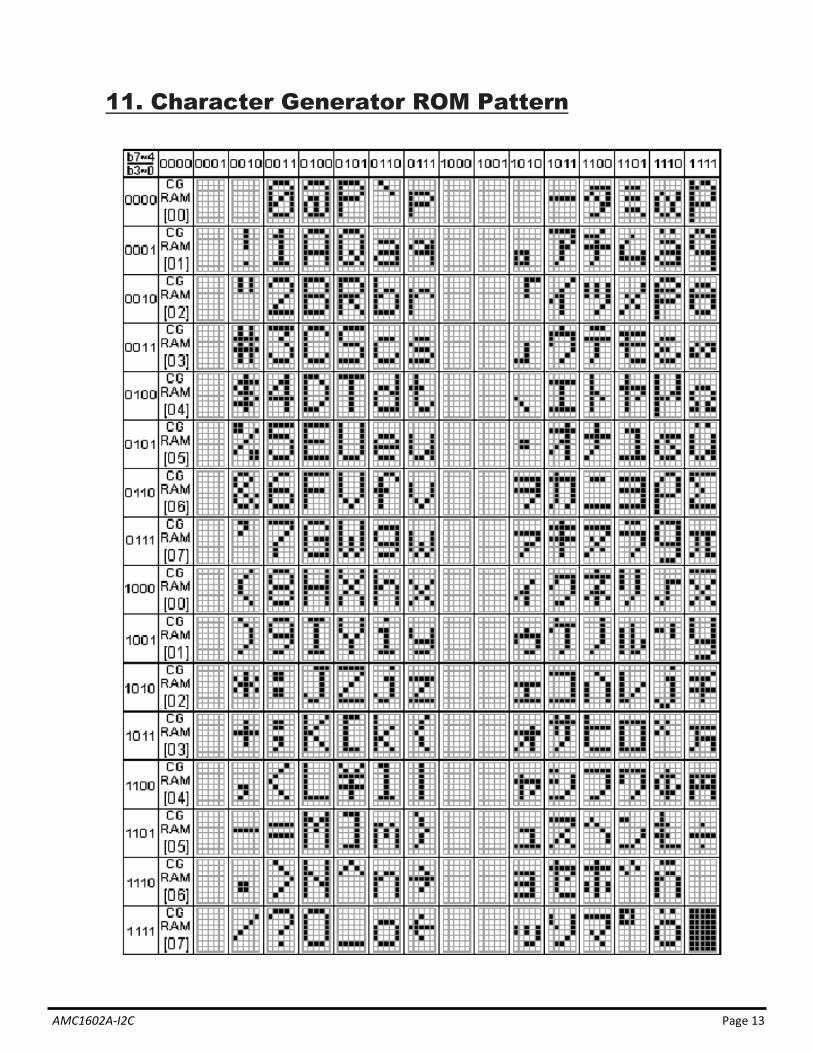
Character Generator ROM (CGROM) The CGROM generate 5×8 dot or 5×10 dot character patterns from 8-bit character codes. See Table 2.
Character Generator RAM (CGRAM) In CGRAM, the user can rewrite character by program. For 5×8 dots, eight character patterns
AC (hexadecimal)
High bits Low bits
AC6 AC5 AC4 AC3 AC2 AC1 AC0 1 0 0 1 1 1 0
Example: DDRAM addresses 4E
Display position DDRAM address
00 01 02 03 04 05 06 07 08 09 0A 0B 0C 0D 0E 0F 40 41 42 43 44 45 46 47 48 49 4A 4B 4C 4D 4E 4F
-Line by 16-Character Display
1 2 3 4 5 6 7 8 9 10 11 12 13 14 15 16
AMC1602A-I2C

Page 12
can be written, and for 5×10 dots, four character patterns can be written. Write into DDRAM the character code at the addresses shown as the left column of table 1. To show the character patterns stored in CGRAM.
Relationship between CGRAM Addresses, Character Codes (DDRAM) and Character patterns Table 1
F o r 5 * 8 d o t c h a r a c te r p a t te r n s
C h a r a c te r C o d e s( D D R A M d a ta ) C G R A M A d d r e s s C h a r a c te r P a t te r n s
( C G R A M d a ta )
5 4 3 2 1 067 5 4 3 2 0 012345671
0 0 000 110 010 101 001 111 011 100 000 110 010 101 001 111 011 100 000 1
01 001 111 011 1
* * ** * ** * ** * ** * ** * ** * ** * * 0 0 0 0 0* * ** * ** * ** * ** * ** * ** * ** * * 0 0 0 0 0
0 0 0 00 0 0 0
0 0 0 0
0 0 00 0 0
0 0 00 0 00 0 0
00 0 00 0 0
0
0 0 0
00 1
* * *
* * *
1 1 10 0 0 0 * 1 1 1
0 0 0 0 * 0 0 0
0 0 0 0 * 0 0 1
H ig h L o w H ig h L o w H ig h L o w
F o r 5 * 1 0 d o t c h a r a c te r p a t te r n sC h a r a c te r C o d e s( D D R A M d a ta ) C G R A M A d d r e s s C h a r a c te r P a t te r n s
( C G R A M d a ta )
7
H ig h L o w
456 3 2 1 0
H ig h L o w
5 4 3 2 1 0
H ig h L o w
7 6 5 4 123 0
* * * 0 0 0 0 00 0 0 0 0* * *
* * ** * ** * ** * ** * ** * ** * ** * ** * *
* * * * * * * *
0 0 0 00 0 0 10 0 1 00 0 1 10 1 0 00 1 0 10 1 1 00 1 1 11 0 0 01 0 0 11 0 1 0
1 1 1 1
0 0 0 0 0
0 0 0 0 * 0 0 0 0 0
0 00 0
0 0 00 0 0
00 0 0 00 0 0 00 0 0 0
C h a r a c te rp a t te r n ( 1 )
C u r s o r p a t te r n
C h a r a c te rp a t te r n ( 2 )
C u r s o r p a t te r n
C h a r a c te rp a t te r n
C u r s o r p a t te r n
: " H ig h "
AMC1602A-I2C
Page 13
11. Character Generator ROM Pattern
AMC1602A-I2C

Page 14
12. Instruction Table
Instruction Instruction Code
Description Execution time (fosc=210Khz)
RS R/W DB7 DB6 DB5 DB4 DB3 DB2 DB1 DB0
Clear Display 0 0 0 0 0 0 0 0 0 1 Write “20H” to DDRAM and set DDRAM address to “00H” from AC
1.98ms
Return Home 0 0 0 0 0 0 0 0 1
Set DDRAM address to “00H” from AC and return cursor to its original position if shifted. The contents of DDRAM are
not changed.
1.98ms
Entry Mode Set
0 0 0 0 0 0 0 1 I/D SH Assign cursor moving direction and enable the shift of entire display.
48�s
Display ON/OFF
0 0 0 0 0 0 1 D C B Set display (D), cursor (C), and blinking of cursor (B) on/off control bit.
48�s
Cursor or Display Shift
0 0 0 0 0 1 S/C R/L Set cursor moving and display shift
control bit, and the direction, without changing of DDRAM data.
48�s
Function Set 0 0 0 0 1 DL N F
Set interface data length (DL:8-bit/4-bit), numbers of display line (N:2-line/1-line)and, display font type
(F:5×11 dots/5×8 dots)
48�s
Set CGRAM Address
0 0 0 1 AC5 AC4 AC3 AC2 AC1 AC0 Set CGRAM address in address counter. 48�s
Set DDRAM Address
0 0 1 AC6 AC5 AC4 AC3 AC2 AC1 AC0 Set DDRAM address in address counter. 48�s
Write Data to RAM
1 0 D7 D6 D5 D4 D3 D2 D1 D0 Write data into internal RAM (DDRAM/CGRAM).
48�s
” ”
AMC1602A-I2C

Page 15
13. Interface with MPU
AMC1602A-I2C

Page 16AMC1602A-I2C

Page 17
Slave Address Option: J8,J10 short,J7,J9open, SA1=0,SA0=0(default setting); J8,J9 short,J7,J10open, SA1=0,SA0=1; J7,J10 short,J8,J9open, SA1=1,SA0=0; J7,J9 short,J8,J10open, SA1=1,SA0=1;
DB5(CSB)is connected to Vss by short J6.
AMC1602A-I2C

Page 18
14. Initializing of LCM
AMC1602A-I2C

Page 19
Initial Code: void WriteData(BYTE byData) { I2C_Start(); I2C_Send(0x78); I2C_Ack(); I2C_Send(0x40); I2C_Ack(); I2C_Send(byData); I2C_Ack(); I2C_Stop(); } void WriteInst(BYTE byInst) { I2C_Start(); I2C_Send(0x78); I2C_Ack(); I2C_Send(0x00); I2C_Ack(); I2C_Send(byInst); I2C_Ack(); I2C_Stop(); } void InitRW1063(void) { WriteInst (0x38); //DL=1: 8 bits; N=1: 2 line; F=0: 5 x 8dots WriteInst (0x0c); // D=1, display on; C=B=0; cursor off; blinking off; WriteInst (0x06); // I/D=1: Increment by 1; S=0: No shift }
AMC1602A-I2C

Page 20
15. Quality Assurance
Screen Cosmetic Criteria noititraP noiretirC tnemgduJ tcefeD metI
1 Spots
A) Clear Size: d mm Acceptable Qty in active area
d 0.1 Disregard 0.1<d 0.2 6 0.2<d 0.3 2 0.3<d 0 Note: Including pin holes and defective dots which must
be within one pixel size. B) Unclear Size: d mm Acceptable Qty in active area d 0.2 Disregard 0.2<d 0.5 6 0.5<d 0.7 2 0.7<d 0
Minor
2 Bubbles in Polarizer
Size: d mm Acceptable Qty in active area d 0.3 Disregard 0.3<d 1.0 3 1.0<d 1.5 1 1.5<d 0
Minor
3 Scratch In accordance with spots cosmetic criteria. When the light reflects on the panel surface, the scratches are not to be remarkable.
Minor
4 Allowable Density Above defects should be separated more than 30mm each other. Minor
5 Coloration
Not to be noticeable coloration in the viewing area of the LCD panels. Back-light type should be judged with back-light on state only.
Minor
AMC1602A-I2C

Page 21
16. Reliability Content of Reliability Test
Environmental Test
Test Item Content of Test Test Condition Applicable Standard
High Temperature
storage
Endurance test applying the high storage temperature for a long time.
80°C 96hrs ——
Low Temperature
storage
Endurance test applying the high storage temperature for a long time.
-30°C 96hrs ——
High Temperature
Operation
Endurance test applying the electric stress (Voltage & Current) and the thermal stress to the element for a long time.
70°C 96hrs ——
Low Temperature
Operation
Endurance test applying the electric stress under low temperature for a long time.
-20°C 96hrs ——
High Temperature/
Humidity Storage
Endurance test applying the high temperature and high humidity storage for a long time.
80°C, 90%RH 96hrs ——
High Temperature/
Humidity Operation
Endurance test applying the electric stress (Voltage & Current) and temperature / humidity stress to the element for a long time.
70°C, 90%RH 96hrs ——
Temperature Cycle
Endurance test applying the low and high temperature cycle. -30°C 25°C 80°C 30min 5min 30min 1 cycle
-30°C �80°C 10 cycles ——
Mechanical Test
Vibration test Endurance test applying the vibration during transportation and using.
10~22Hz�1.5mmp-p 22~500Hz�1.5G
Total 0.5hrs ——
Shock test Constructional and mechanical endurance test applying the shock during transportation.
50G Half sign wave 11 msedc 3 times of each
direction
——
***Supply voltage for logic system=5V. Supply voltage for LCD system =Operating voltage at 25°C
AMC1602A-I2C