Embed Size (px)
Citation preview

SPECIFICATION FOR HIGH DENSITY POLYETHYLENE (HDPE) PIPEWORKS
SPECIFICATION SAJ PW / HDPE / 001
(Rev.6.0 /04.2019)
QUALITY ASSURANCE DEPARTMENT
RANHILL SAJ SDN. BHD.
NO CHANGES ALLOWED WITHOUT THE PERMISSION OF QUALITY ASSURANCE DEPARTMENT` OF RANHILL SAJ SDN BHD
Ref. No. : PW/HDPE/001
Date : 25/4/2019
Total Pages : 29/29

QUALITY ASSURANCE DEPARTMENT RANHILL SAJ SDN BHD
SAJ PS/HDPE/001 (Rev.6.0 / 04.2019) NO CHANGES ALLOWED WITHOUT THE PERMISSION OF QUALITY ASSURANCE DEPARTMENT OF RANHILL SAJ SDN BHD Page 2 Page 2
SPECIFICATION FOR HIGH DENSITY POLYETHYLENE PIPEWORKS
CONTENT Page
1.0 HAULING AND HANDLING 3
2.0 HDPE PIPE LAYING 4
3.0 HDPE JOINTING METHOD 8
4.0 INSTALLATION OF HDPE PIPES 19
5.0 REPAIR METHODS 20
6.0 CONSTRUCTION OF THRUST AND ANCHOR BLOCKS 21
7.0 VALVE INSTALLATION 22
8.0 STEP-BY-STEP INSTALLATION 23
9.0 COMMUNICATION PIPE BACKFILL 26
10.0 COMPACTION EQUIPMENTS 26
11.0 SOIL TESTING 27
12.0 HDPE PIPELINES TESTING 27

QUALITY ASSURANCE DEPARTMENT RANHILL SAJ SDN BHD
SAJ PS/HDPE/001 (Rev.6.0 / 04.2019) NO CHANGES ALLOWED WITHOUT THE PERMISSION OF QUALITY ASSURANCE DEPARTMENT OF RANHILL SAJ SDN BHD Page 3 Page 3
SPECIFICATION FOR HIGH-DENSITY POLYETHYLENE (HDPE) PIPEWORKS
1.0 HAULING AND HANDLING
Great care shall be exercised to ensure that the pipes and specials are not subject to any kind of shock or
sudden load during hauling and handling.
All pipes and pipe specials shall be lifted by means of reinforced canvas slings. For pipe length greater
than 6 m, the pipe shall be lifted by crane using spreader beam and suitable slings. Chains or end hooks
should not be used. Care should be taken to avoid damage to pipes and pipe ends during lifting. On no
account shall the pipes and specials be dropped or let fall onto the ground.
The pipe shall be stacked and supported on wooden saddles and shall be firmly held in position at each
wooden saddle by straps tightened by turnbuckles in such a manner that the external coating is not
damaged as shown in Figure 1 (example for 6m, 9m and 12m length of pipes). Two saddles shall be
placed 0.5m from each end of pipes and approximately maximum 2m spacing under the rest of the pipes.
The spacing of the saddles shall be not more than 2m.
Figure 1: Saddle as pipe support
When the pipes are properly stacked, the pipes shall be covered with canvas at the top in order to protect
the pipes from hot temperature and to ensure the safety of the pipe. Besides that, end caps also shall be
installed at the ends of each pipes to ensure that there is no soils, rubbish and etc. remains in the pipe.
The contractor shall make sure the pipe is in clean condition before, during and after pipe laying.

QUALITY ASSURANCE DEPARTMENT RANHILL SAJ SDN BHD
SAJ PS/HDPE/001 (Rev.6.0 / 04.2019) NO CHANGES ALLOWED WITHOUT THE PERMISSION OF QUALITY ASSURANCE DEPARTMENT OF RANHILL SAJ SDN BHD Page 4 Page 4
For similar reasons, pipe coils should be stored flat and the number of coils per stack should be limited to:
7 coils for 20mm pipe
6 coils for 25mm pipe
5 coils for 32mm pipe
4 coils for 50mm pipe
3 coils for 63mm pipe
2 coils for 90mm pipe
Where the individual pipe lengths are stacked in pyramidal fashion, deformation may occur in the lower
layers. Such stacks should therefore be not greater than 1m high as shown in Figure 2.
Figure 2: Individual pipe storage
2.0 HDPE PIPE LAYING
2.1 Pipe Alignment, Cover and Bedding
Generally, for pipe work of diameter below 1000 mm, at road crossing and along the road, the minimum
cover to the top of pipes shall be 1200 mm. For major pipe work of diameter 1000 mm and above, the
minimum cover to the top of pipes shall be 1000 mm unless otherwise shown on the drawing.
Before commencing excavation the route of the pipeline shall be pegged accurately. Strong sight rails
shall be fixed and maintained at each change of direction and gradient, and at as many intermediate
points not more than 25 m apart as may be necessary. On these rails shall be marked the center line and
the level to which the pipe is to be laid.
The trench bottom shall be free from all rocks, boulders, stones or hard particles which may damage the
pipe walls.
A minimum distance of 600 mm radius from any obstruction and other services shall always be
maintained.

QUALITY ASSURANCE DEPARTMENT RANHILL SAJ SDN BHD
SAJ PS/HDPE/001 (Rev.6.0 / 04.2019) NO CHANGES ALLOWED WITHOUT THE PERMISSION OF QUALITY ASSURANCE DEPARTMENT OF RANHILL SAJ SDN BHD Page 5 Page 5
2.2 Preparation of Pipes
Generally HDPE pipes are joined to form a string above ground prior to snaking into the trench. To
prevent scoring, pipe rollers should be used. Pipe ends have to be kept closed with standard end caps
provided by the pipe supplier until they are welded to another pipe or fitting. This is to prevent any debris,
dirt, stones or other matter to enter the pipe.
The pipes or fittings shall be inspected for deep cuts or scratches, pipes with cuts or scratches which are
deeper than 10% of the pipe wall thickness shall be rejected. The depth shall be measured with calibrated
depth gauges of suitable accuracy. All damaged or flawed section of pipes shall be cut out and removed
to the satisfaction of the Supervisor before jointing can proceed.
Before lowering HDPE pipelines into the trench, a check should be made for cuts, deep scratches or
other pipe damage and in fusion jointed system that the system has cooled sufficiently before stress is
imposed upon any pre-made joints.
2.3 Laying of Pipes
Before any pipes or specials are lowered into the trench, the pipes and specials are to be rechecked for
deep cut and scratches as described above and the fusion joints must have cooled sufficiently (specified
cooling time for the last joint has elapsed) before stress is imposed upon any premade joints. When
lowering pipe into trenches, care should be taken to avoid scoring of the pipe by contact with the sides
and bottom of the trench. Special care shall be needed when passing under/around obstruction or other
utilities. Pipe roller supports for the first four lengths of pipes from the pipe end to be lowered into the
trench shall be provided. Cut section of rejected or damaged HDPE pipes, planks and rope shall be used
for protecting the remaining pipes where appropriate but wire ropes or chain shall not be used. Figure 3
shows the method to lower the pipe into trench by using canvas sling rope.
Figure 3: Lowering the pipe into the trench
Gradual changes in direction of HDPE pipelines can be accommodated by the pipe. The pipe shall be
kept as central as possible within the trench to enable correct side-fill compaction but some snaking to
compensate for thermal expansion of the pipe will be allowed.
If any debris, dirt, stones or other matter have entered the pipe during laying, the removal, flushing and
disinfection of the whole pipe will be at the Contractor’s cost.

QUALITY ASSURANCE DEPARTMENT RANHILL SAJ SDN BHD
SAJ PS/HDPE/001 (Rev.6.0 / 04.2019) NO CHANGES ALLOWED WITHOUT THE PERMISSION OF QUALITY ASSURANCE DEPARTMENT OF RANHILL SAJ SDN BHD Page 6 Page 6
All open ends of pipes and specials in the trench shall be kept closed by means of the standard end caps
delivered by the supplier.
The bending of HDPE pipelines is permissible and the properties of fusion jointed systems enable
changes of direction without recourse to the provision of special bends or anchor blocks. Bending must
not exceed the manufacturer’s minimum recommended bend radius (25 times pipe diameter).
After completion of an installation, pipe work and fittings should be inspected and made ready for testing
to ensure the safety and efficiency of the systems. The trench shall be backfilled prior to testing; but the
mechanical joints and electro-fusion joints shall be exposed during the test except if approved by the
Supervisor.
Before connection, the pipe has to be flushed until clear water is registered to prevent debris, dirt, stones
or other matter to enter the system.
2.4 Pipe Laying in Grounds with High Water Table.
The contractor shall note that some parts of the pipeline will be laid in grounds with high water table,
especially in areas adjacent to the streams, river crossings and ponds in the vicinity.
All costs for dewatering and keeping all the excavations and trenches dry for the whole pipe laying work
and in a safe manner during construction shall be deemed to be included in the Contract Rates except
where specific provision is made in the Bill of Quantities.
2.5 Trenchless Pipe Laying
HDPE pipes are very suited for trenchless pipe laying techniques. The use of trenchless pipe laying is
decided during the design phase. The following techniques can be used:
2.5.1 Impact Moling
Impact moling can be used to lay smaller diameter pipelines over shorter distances as shown in Figure 4.
This method can be used to lay communication pipe. Focus shall be on the inaccuracy of the method and
the risk of deflection.
Figure 4: Impact moling method
QUALITY ASSURANCE DEPARTMENT RANHILL SAJ SDN BHD
SAJ PS/HDPE/001 (Rev.6.0 / 04.2019) NO CHANGES ALLOWED WITHOUT THE PERMISSION OF QUALITY ASSURANCE DEPARTMENT OF RANHILL SAJ SDN BHD Page 7 Page 7
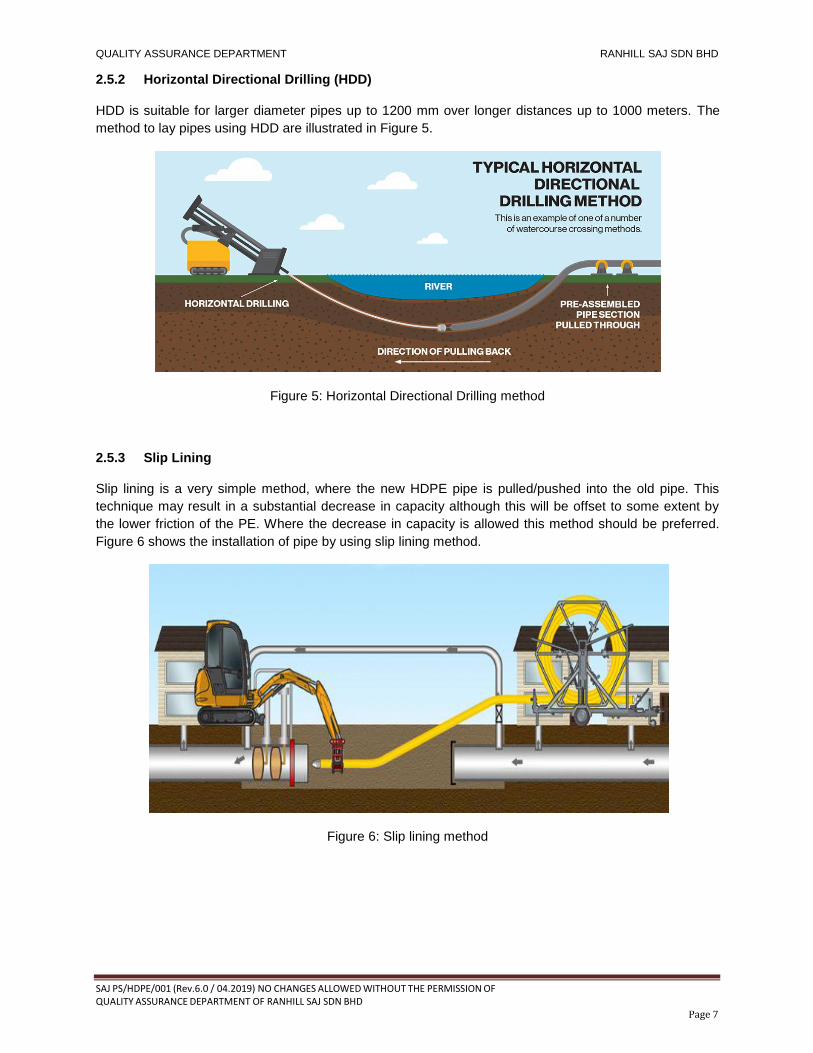
2.5.2 Horizontal Directional Drilling (HDD)
HDD is suitable for larger diameter pipes up to 1200 mm over longer distances up to 1000 meters. The
method to lay pipes using HDD are illustrated in Figure 5.
Figure 5: Horizontal Directional Drilling method
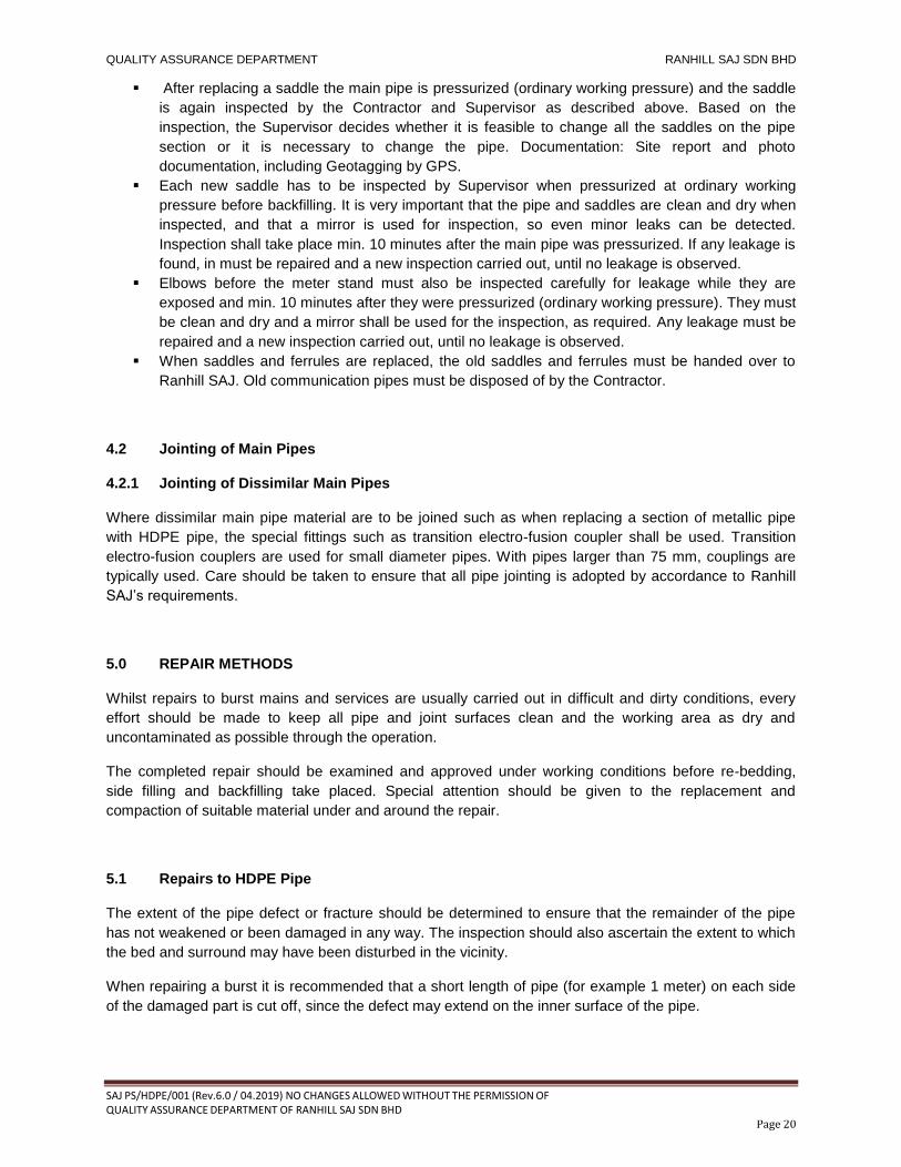
2.5.3 Slip Lining
Slip lining is a very simple method, where the new HDPE pipe is pulled/pushed into the old pipe. This
technique may result in a substantial decrease in capacity although this will be offset to some extent by
the lower friction of the PE. Where the decrease in capacity is allowed this method should be preferred.
Figure 6 shows the installation of pipe by using slip lining method.
Figure 6: Slip lining method

QUALITY ASSURANCE DEPARTMENT RANHILL SAJ SDN BHD
SAJ PS/HDPE/001 (Rev.6.0 / 04.2019) NO CHANGES ALLOWED WITHOUT THE PERMISSION OF QUALITY ASSURANCE DEPARTMENT OF RANHILL SAJ SDN BHD Page 8 Page 8
2.5.4 Pipe Bursting
Pipe bursting can be used where decrease in capacity cannot be accepted. This method involves the
installation of a bigger size of pipe over the existing pipe. The illustration of pipe bursting method are as
shown in Figure 7.
Figure 7: Pipe bursting method
3.0 HDPE Jointing Method
The pipes and fittings shall be jointed by electro-fusion or butt fusion to form a string above the ground
and shall be supported by smooth rollers support. Three standard lengths of pipe on each side of the
fusion machine shall have a minimum of two (2) roller supports per length of the pipe. Never use wooden
blocks or similar instead of roll bending, since the friction will be highly volatile, providing improper
welding pressure. Let protective caps on the free end of the tube to be.
Heat fusion joining may be performed in any season and in hot or cold conditions. During bad weather, a
temporary shelter should be set-up around the joining operation to shield heat fusion operations from rain
and high wind conditions. Wind chill can reduce heating plate temperature or chill melted component
ends before joining. If fusion joining operations cannot be protected against dust contamination during
severe windblown dust conditions, joining shall be suspended until conditions improve.
The selection of HDPE jointing method (electro-fusion, butt fusion or mechanical jointing method)
depends on the condition of work area. The butt fusion jointing method should be used as preferred
method of jointing. The use of electro-fusion and butt fusion joints shall be approved by the Supervisor.
The process of conducting the electro-fusion and butt fusion are explain as follows:

QUALITY ASSURANCE DEPARTMENT RANHILL SAJ SDN BHD
SAJ PS/HDPE/001 (Rev.6.0 / 04.2019) NO CHANGES ALLOWED WITHOUT THE PERMISSION OF QUALITY ASSURANCE DEPARTMENT OF RANHILL SAJ SDN BHD Page 9 Page 9
3.1 Electro-fusion Jointing
Electro-fusion is a method of joining HDPE pipes using special fittings that have built-in electric heating
elements which are used to weld the joint together. Electro-fusion jointing can be conducted from pipe
size of 20 mm and above.
3.1.1 Electro-fusion Jointing Process
1) CUT
The pipe shall be cut neatly and
accurately performed so as to leave
the pipe ends to be jointed are cut
square (90°).
The pipe shall only be cut by a
universal pipe cutter
2) MARKING
Mark the length of the penetration
depth which the contaminated area to
be removed on each pipe to be
jointed.
Trace a line round the circumference
at the appropriate distance from the
pipe using suitable marker.
3) SCRAP
Using the mechanical or rotational
peeling tool, remove the entire
surface of the pipe uniformly,
preferably as a continuous swarf over
the area identified, i.e. the excess of
the penetration depth.
4) WIPE CLEAN
Remove the fitting from its packaging
and check that the bore of the fitting
is clean and dry.
Clean the section to be jointed and
fittings by using disposable, lint-free
material and degrease with a clean
cloth dampened by a suitable solvent
such as alcohol like IPA or a cleaning
liquid from the welding machine
supplier.

QUALITY ASSURANCE DEPARTMENT RANHILL SAJ SDN BHD
SAJ PS/HDPE/001 (Rev.6.0 / 04.2019) NO CHANGES ALLOWED WITHOUT THE PERMISSION OF QUALITY ASSURANCE DEPARTMENT OF RANHILL SAJ SDN BHD Page 10 Page 10
3.1.2 Surface Preparation
In order to achieve a good weld the oxidized surface of the pipe must first be removed. The
removal of this oxidized surface layer is achieved using a mechanical peeling tool.
Consistent peeling to the correct depth is critical to the success of the welding process and the only
effective means of achieving this is to use a mechanical or rotational peeling tool. Therefore only
mechanical or rotational peeling tools should be used. Hand scrapers are allowed to be used only
for communication pipe and at location where branch saddle will be installed. Table 1 shows the
allowable peeling depth of pipes.
Table 1: Allowable Peeling Depth of Pipes
Nominal Diameter of Pipe Peel Depth (mm)
≤ DN25 0.2 max
DN32 – DN63 0.2 - 0.3
DN75 – DN225 0.2 – 0.4
> DN225 0.3 – 0.5
5) CHECK THE PIPE ALIGNMENT
Using the pipe clamps, secure the
pipes so that the pipe does not move
during the fusion period.
6) CONNECT, INSERT INPUT AND SCAN
Connect the control box output leads
to the fitting and check that they have
been fully inserted.
Switch on the control box.
Commence the fusion joining
procedure in accordance with the
control box instruction and check
indicated joining time with time shown
on the fitting.
Scan the bar code magnetic card
which is provided together with the
fusion socket.
7) FUSION PROCESS
Press the start button on the control
box and check that the heating cycle
is proceeding as indicated by the
display countdown.
On completion of the heating cycle,
the melt indicator should have risen.

QUALITY ASSURANCE DEPARTMENT RANHILL SAJ SDN BHD
SAJ PS/HDPE/001 (Rev.6.0 / 04.2019) NO CHANGES ALLOWED WITHOUT THE PERMISSION OF QUALITY ASSURANCE DEPARTMENT OF RANHILL SAJ SDN BHD Page 11 Page 11
3.1.3 Records
Written records (i.e. joint number, ambient temperature, fusion time, cooling time, and joint status) of the
jointing shall be obtained from the control box and shall be kept as required.
All fusion joints shall be inspected and assessed with joint record printouts from the electro-fusion
machine. All joints shall be approved before the contractor is allowed to proceed with pipe laying works.
3.1.4 Electro-fusion Jointing Inspection
There are few criteria of electro-fusion jointing visual inspection that need to be checked by Supervisor
after the jointing process has been done. The criteria are as follows:
i. Fusion melt indicator present on the fitting.
ii. Pipe ends are cut perpendicular to the pipe.
iii. The welded elements must be correctly aligned.
iv. The scrapped area must be clearly visible.
v. The insertion depth previously marked on the elements to be welded must be respected.
vi. No protrusion of melted material and damages on the outside surface of the welded elements are
shown.
vii. Take care also of the possible error messages on the display of the electro-fusion control unit
used for the jointing operation.
3.2 Butt Fusion Jointing
Butt fusion is a process of welding HDPE pipes and fittings using and electrically heated plate. It is
suitable for jointing HDPE pipes and fittings of size from 110 mm outside diameter and above.
3.2.1 Butt Fusion Jointing Equipment
Butt fusion jointing equipment shall be certified in accordance with MS 1058 or ISO 12176. The
equipment used is as follows:
a. Chassis and Clamps
Chassis and clamps which are sufficiently robust to accurately align the pipe to be jointed and
have insert rings to fit different pipe diameters. The base framework shall be fitted with a
minimum of four clamps, two fixed and two moveable, to position the pipes during the fusion
cycle. These clamps shall be designed to enable the pipes to be positioned or removed quickly.
QUALITY ASSURANCE DEPARTMENT RANHILL SAJ SDN BHD
SAJ PS/HDPE/001 (Rev.6.0 / 04.2019) NO CHANGES ALLOWED WITHOUT THE PERMISSION OF QUALITY ASSURANCE DEPARTMENT OF RANHILL SAJ SDN BHD Page 12 Page 12
b. Hydraulic/pneumatic unit
The unit shall be capable of actuating the clamp unit to provide adequate force and speed of
operation. A pressure monitoring device shall be provided to monitor ram pressure. The pressure
required shall be automatically set and calculated by the control box.
c. Trimming tool
The trimming tool shall be capable of being mounted securely within the frame of the jointing
machine, so that this equipment can produce accurately matched planed faces.
Trimming blades of the planar shall be sharp and have defect free cutting edges to provide
continuous swarf of uniform thickness.
d. Heater plate
The plate shall be electrically heated to give a uniform surface temperature of 220 to 230 (+/-10)
°C. The heater plate also shall be fitted with an indicator which is capable to show clearly the
actual temperature on site of the heater plate. The heating system shall be designed to ensure
that the pipe is heated up correctly to the operating temperature and stable fusion conditions are
maintained.
The plate surface shall have a permanent coat of anti-stick material. The surface shall be free
from any scratches and contaminants.
e. Control system
The butt fusion machines used for the jointing shall be a semi-automatic system incorporating a
device for monitoring and recording the fusion parameters. Machines are generally designed for
well-defined ranges of diameters, SDR ratios and fusion cycles. Machines which record fusion
data shall be capable of transferring the data for further use. The machines also shall be capable
of recording the actual temperature of the heater plate in the fusion records.
f. Shelter
A shelter shall be used to provide adequate protection for pipe, fittings and equipment against
adverse weather conditions and contamination.
g. External and internal bead removal if required
External and internal debeaders shall be capable of removing the cold bead cleanly in a
continuous strip without damage to either joint or bead after the cooling time.
h. Generator
The generator shall be selected to suit the butt fusion machine capacity and heater plate rating.
The specification of the generator shall be supplied by the machine manufacturer.

QUALITY ASSURANCE DEPARTMENT RANHILL SAJ SDN BHD
SAJ PS/HDPE/001 (Rev.6.0 / 04.2019) NO CHANGES ALLOWED WITHOUT THE PERMISSION OF QUALITY ASSURANCE DEPARTMENT OF RANHILL SAJ SDN BHD Page 13 Page 13
i. Ancillary equipment
The following equipment shall be made available on site:
(a) Pipe support rollers
(b) Pipe cutters
(c) Digital thermometer with indicator
(d) Timer
(e) Marker pen for marking beads
(f) Pipe end cover
(g) Spirit level to ensure machine is level
(h) Isopropyl alcohol (IPA)
(i) Clean and lint-free paper to wipe the alcohol or cleaning liquid
All equipment shall be well maintained and kept in a clean condition at all time, both in stores and
on site.
The equipment shall be serviced and calibrated regularly. The frequency at which this is carried
out will be different for individual items of equipment and will also depend on usage but should be
at least once every 6 months.

QUALITY ASSURANCE DEPARTMENT RANHILL SAJ SDN BHD
SAJ PS/HDPE/001 (Rev.6.0 / 04.2019) NO CHANGES ALLOWED WITHOUT THE PERMISSION OF QUALITY ASSURANCE DEPARTMENT OF RANHILL SAJ SDN BHD Page 14 Page 14
3.2.2 Butt Fusion Jointing Procedure
The process of conducting butt fusion jointing are as shown in the chart below.
The hot plate temperature must be 220 to 230 (+/-10) °C.
The hot plate must be clean and free from grease.
Ensure that the two pipe brackets and the two pipe supports are correctly aligned.
Both pipe clamps must be adjusted so that they hold the pipe tightly enough to
withstand the force of the welding process.
Press the pipe ends against hot plate by applying the pressure provided by the
supplier.
After reaching a correct bead size at the heating plate release pressure and start the soaking time given by the supplier.
After end of soaking time quickly remove the hot plate and slowly increase the
welding pressure.
Hold the weld pressure steady and allow the weld to cool.
Remove the joint and inspect the weld. An irregular weld seam should be rejected.

QUALITY ASSURANCE DEPARTMENT RANHILL SAJ SDN BHD
SAJ PS/HDPE/001 (Rev.6.0 / 04.2019) NO CHANGES ALLOWED WITHOUT THE PERMISSION OF QUALITY ASSURANCE DEPARTMENT OF RANHILL SAJ SDN BHD Page 15 Page 15
Check surface temperature of the heating plate with an external digital thermometer two times every day.
First time by start up in the morning and the second time after lunch.
Joint quality shall be checked by visual inspection and approved by the Supervisor. Hydraulic butt fusion
equipment shall be fitted for connection to data logging devices that can record equipment temperature,
time and pressure conditions during joining. The record shall be used to document equipment conditions
when making field fusions, and to supplement field joining quality assurance visual inspection and
procedural oversight.
Data logger records shall be used to compare equipment operation during field fusion joining to data
logger equipment operation records of properly made fusions.
3.2.3 Welding Personnel
Only trained and certified welders shall be employed to carry out the butt and electro-fusion jointing. The
contractor is required to show proof of the competency of their PE welders in forms of certificates from
pipe manufacturers in using the specified automatic machines for butt fusion and electro-fusion jointing.
3.2.4 Butt Fusion Jointing Inspection
The butt fusion jointing shall be visually inspected by the Supervisor in order to verify the jointing result.
Proposed visual inspection criteria for butt fusion joints are indicated below. The contractor shall either
accept these inspection criteria or with his tender propose and justify alternative criteria, based on
information from the pipe manufacturer.
The size of the welded bead B should be as shown in the Table 2 below and should be measured with a
caliper for every joint.
Table 2: Allowable bead dimension
Outside Diameter (mm)
Wall Thickness (mm) SDR Bead Width (mm)
110 10.0 11 8-13
125 11.4 11 9-14
160 14.6 11 10-17
180 16.4 11 11-18
200 18.2 11 12-19
225 20.5 11 12-21
250 22.7 11 13-22
280 25.4 11 14-23
315 28.6 11 15-24
355 32.2 11 16-26
400 36.3 11 17-28
450 40.9 11 18-30
500 45.4 11 20-32
560 50.8 11 22-34
630 57.2 11 24-37
If the bead is smaller or bigger than shown in the table the welding has to be rejected.

QUALITY ASSURANCE DEPARTMENT RANHILL SAJ SDN BHD
SAJ PS/HDPE/001 (Rev.6.0 / 04.2019) NO CHANGES ALLOWED WITHOUT THE PERMISSION OF QUALITY ASSURANCE DEPARTMENT OF RANHILL SAJ SDN BHD Page 16 Page 16
Besides the size of the bead there are other characteristics of the bead that need to be visually evaluated,
but not necessarily have to be measured if the visual inspection indicates that the joint is acceptable.
If the beads appear uniform and even and seem to be same size and the V-groove between the beads
does not seem to be below pipe diameter and there is no visible misalignment between the welded pipe
ends, no further action is required.
If the beads by visual inspection are not uniform and even the welding has to be rejected. If the beads do
not seem to have the same size or there is a misalignment between the pipe ends the following have to
be measured:
Table 3: Visual inspection criteria
Criteria Figure
The V-groove A must not be under pipe surface.
The misalignment v between the welded pipe ends may not exceed 10% of the wall thickness.
The bead width should only vary +/- 20% from the average bead width BM
The average bead width BM is calculated so:
BM =
Hereby: Bmin ≥ 0,8 x BM
Bmax ≤ 1.2 x BM

QUALITY ASSURANCE DEPARTMENT RANHILL SAJ SDN BHD
SAJ PS/HDPE/001 (Rev.6.0 / 04.2019) NO CHANGES ALLOWED WITHOUT THE PERMISSION OF QUALITY ASSURANCE DEPARTMENT OF RANHILL SAJ SDN BHD Page 17 Page 17
S: Single bead width Δs: The difference between the two single beads (Smax - Smin) B: The double bead width The difference between the two single beads should not at any given place exceed X% of the double bead width at the same place
( X =
x 100)
It leads to: X ≤ 10% for pipe against pipe implying Δs ≤ 0.1 x B X ≤ 20% for pipe against fittings, implying Δs ≤ 0.2 x B X ≤ 20% for fittings against fittings, implying Δs ≤ 0.2 x B
3.2.5 Butt Fusion Troubleshooting Guide
There are some troubleshooting guidelines that can be used as a reference during the visual inspection
by the Supervisor. The observed condition and possible causes are as listed in the Table 4 below.
Table 4: Butt fusion troubleshooting guidelines
Observed Condition Possible Cause
Excessive double bead width Overheating, excessive joining force
Double bead v-groove too deep Excessive joining force, insufficient heating, pressure during heating
Flat top on bead Excessive joining force, overheating
Non-uniform bead size around pipe Misalignment, defective heating tool, worn equipment, incomplete facing
One bead larger than the other Misalignment component slipped in clamp, worn equipment, defective heating tool, incomplete facing
dissimilar material
Beads too small Insufficient heating, insufficient joining force
Beads not rolled over the surface Shallow v-groove - insufficient heating and insufficient joining force
Deep v-groove – insufficient heating and excessive joining force
Beads too large Excessive heating time
Squareish outer bead edge Pressure during heating
Rough, sandpaper-like, bubbly, or pockmarked melt bead surface
Hydrocarbon contamination

QUALITY ASSURANCE DEPARTMENT RANHILL SAJ SDN BHD
SAJ PS/HDPE/001 (Rev.6.0 / 04.2019) NO CHANGES ALLOWED WITHOUT THE PERMISSION OF QUALITY ASSURANCE DEPARTMENT OF RANHILL SAJ SDN BHD Page 18 Page 18
3.3 Mechanical Jointing
Mechanical joint can only be used when it involves HDPE pipe jointing with flanges. For mechanical
joints, flanges and adaptors must be approved and also must have a pressure rating equal to the pipe.
For transition from HDPE pipe to flanged metal fittings, either HDPE stub end flanges with metal backing
rings or mechanical flange adaptors of approved types complying with MS 1058 shall be used as shown
in Figure 8. This connection is made by first sliding the Back-Up Ring over the pipe end and
then fuse the HDPE flange adapter to the end of the pipe by using electro-fusion jointing. The flange joint
gasket and bolt length used shall be appropriate to the particular adaptor. When tightening the bolts and
nuts to the flanges, care should be taken to produce an even torque load by using torque wrench to the
limits. The use of torque wrench is compulsory. Typical bolt torques as tabulated in Table 5 below.
Figure 8: DI flange adaptor and stub end used in mechanical jointing
Table 5: Typical Bolt Torques
Nominal Pipe Size, mm
Standard Flanges
Nominal Iron Size, mm
Number of Bolts Torque, Nm (+/- 10%)
63 90 125 180 225 250 280 315 355 400 450 500
50 80 100 150 200 250 250 300 350 400 450 500
4 8 8 8
12 12 12 12 16 16 20 20
35 35 35 60 80 100 100 120 150 200 250 300
For installation of heavy flanged fittings, provision should be made for concrete support both for the
weight and to resist the turning moments associated with valves and hydrants.
Jointing of DI valve with HDPE stub end
HDPE stub end and backing ring

QUALITY ASSURANCE DEPARTMENT RANHILL SAJ SDN BHD
SAJ PS/HDPE/001 (Rev.6.0 / 04.2019) NO CHANGES ALLOWED WITHOUT THE PERMISSION OF QUALITY ASSURANCE DEPARTMENT OF RANHILL SAJ SDN BHD Page 19 Page 19
4.0 INSTALLATION OF HDPE PIPES
4.1 Communication Pipe
4.1.1 Laying Communication Pipe
Wherever practicable the whole communication pipe should be laid in a straight line at right angles to the
main when viewed on plan. This assists future location and identification of these pipes.
Slight snaking of the communication pipe in the vertical plane is permitted without overstressing the
connection to the main. However, care must be taken not to kink the pipe and/or impart excess bending
moment to the saddle tapping.
The preferred method would seem to be simple straight connection at right angles to the main with
changes in direction or level achieved by installation of electro-fusion elbows to avoid overstressing of the
communication pipe.
When the new communication pipe shall be connected to existing Non-HDPE pipe, the procedure shall
be based on the condition of the existing pipe.
4.1.2 Connection to HDPE Main Pipe
Connection to HDPE pipe shall vary according to size. Large branch connection are usually effected by
electro-fusion branch tees, while medium size are effected by electro-fusion branch saddles. Other
communication pipe connections (<63mm) are usually effected by electro-fusion tapping saddles.
Electro-fusion tapping saddle have a self-tapping ferrule system whereby the cutter forms an integral part
of the ferrule connection and after withdrawal remains within the ferrule head.
4.1.3 Connection to Pipes of Other Main Pipe Materials
HDPE communication pipe may be connected to other pipe materials such as DI, AC, uPVC, MS etc. The
use of DI saddle is usually required for tapping to DI, AC and uPVC pipes.
For each pipe section the following procedure has to be followed:
Excavation of trial pit at one saddle. Trench has to be at least 200 mm under the bottom of the
pipe to facilitate visual leakage inspection.
Visual inspection of pipe and saddle by Contractor and Supervisor. A mirror must be used for the
inspection. It is very important that the pipe and saddles are clean and dry when inspected, so
even minor leaks can be detected. If the pipe is in too poor condition to safely change the saddle
decision has to be made if the pipe shall be replaced or there will be no further work on this pipe
section.
If the pipe is in good condition the saddle is replaced. Immediately before replacement the
nearest upstream valve is closed, The contractor and/or the Supervisor shall feel with a finger if
there is any sign of corrosion or cracks at the tapping point and if yes, the pipe, or a section of the
pipe, should be replaced. Before fitting a new saddle, the pipe must be cleaned carefully with a
steel brush.
QUALITY ASSURANCE DEPARTMENT RANHILL SAJ SDN BHD
SAJ PS/HDPE/001 (Rev.6.0 / 04.2019) NO CHANGES ALLOWED WITHOUT THE PERMISSION OF QUALITY ASSURANCE DEPARTMENT OF RANHILL SAJ SDN BHD Page 20 Page 20
After replacing a saddle the main pipe is pressurized (ordinary working pressure) and the saddle
is again inspected by the Contractor and Supervisor as described above. Based on the
inspection, the Supervisor decides whether it is feasible to change all the saddles on the pipe
section or it is necessary to change the pipe. Documentation: Site report and photo
documentation, including Geotagging by GPS.
Each new saddle has to be inspected by Supervisor when pressurized at ordinary working
pressure before backfilling. It is very important that the pipe and saddles are clean and dry when
inspected, and that a mirror is used for inspection, so even minor leaks can be detected.
Inspection shall take place min. 10 minutes after the main pipe was pressurized. If any leakage is
found, in must be repaired and a new inspection carried out, until no leakage is observed.
Elbows before the meter stand must also be inspected carefully for leakage while they are
exposed and min. 10 minutes after they were pressurized (ordinary working pressure). They must
be clean and dry and a mirror shall be used for the inspection, as required. Any leakage must be
repaired and a new inspection carried out, until no leakage is observed.
When saddles and ferrules are replaced, the old saddles and ferrules must be handed over to
Ranhill SAJ. Old communication pipes must be disposed of by the Contractor.
4.2 Jointing of Main Pipes
4.2.1 Jointing of Dissimilar Main Pipes
Where dissimilar main pipe material are to be joined such as when replacing a section of metallic pipe
with HDPE pipe, the special fittings such as transition electro-fusion coupler shall be used. Transition
electro-fusion couplers are used for small diameter pipes. With pipes larger than 75 mm, couplings are
typically used. Care should be taken to ensure that all pipe jointing is adopted by accordance to Ranhill
SAJ’s requirements.
5.0 REPAIR METHODS
Whilst repairs to burst mains and services are usually carried out in difficult and dirty conditions, every
effort should be made to keep all pipe and joint surfaces clean and the working area as dry and
uncontaminated as possible through the operation.
The completed repair should be examined and approved under working conditions before re-bedding,
side filling and backfilling take placed. Special attention should be given to the replacement and
compaction of suitable material under and around the repair.
5.1 Repairs to HDPE Pipe
The extent of the pipe defect or fracture should be determined to ensure that the remainder of the pipe
has not weakened or been damaged in any way. The inspection should also ascertain the extent to which
the bed and surround may have been disturbed in the vicinity.
When repairing a burst it is recommended that a short length of pipe (for example 1 meter) on each side
of the damaged part is cut off, since the defect may extend on the inner surface of the pipe.

QUALITY ASSURANCE DEPARTMENT RANHILL SAJ SDN BHD
SAJ PS/HDPE/001 (Rev.6.0 / 04.2019) NO CHANGES ALLOWED WITHOUT THE PERMISSION OF QUALITY ASSURANCE DEPARTMENT OF RANHILL SAJ SDN BHD Page 21 Page 21
5.2 Emergency Repairs
The emergency temporary repair of a HDPE pipe may be carried out using split collar in the normal way
but a more permanent repair should be undertaken as soon as possible.
For work area unsuitable for conducting the electro-fusion and butt fusion jointing method, a quick
connect fixtures can be done by using special fittings. The Buteline fittings is a simple installation process
which can reduce the installation period. Figure 9 shows the special fittings that can be used in
emergency repair works.
Figure 9: Buteline fitting
5.3 Permanent Repairs Using Fusion Joints
The electro-fusion couplers, after removing the central stopper, may be slipped over the existing pipe
ends and fusion joints made. Care must be taken to ensure all ends are cut square and dry and clean
prior to jointing. Marking of the pipe will ensure that the coupler is placed centrally over the joint.
Besides that, the contractor must ensure that the repair or maintenance pipe work must be done in dry
condition with no presence of water. If there is water in the trench, the water needs to be pumped out or
removed from the trench before the repair or maintenance can proceed.
5.4 Temporary Repairs Using Mechanical Joints
Another alternative means of jointing the replacement pipe is by means of a special mechanical type
repair clamps in accordance to Ranhill SAJ’s requirement. Mechanical fittings are encouraged for site
repair.
6.0 CONSTRUCTION OF THRUST AND ANCHOR BLOCKS
The fusion jointing used for HDPE pipe creates an essentially continuous length of pipe. When the pipe is
pressurized two significant internal forces are present in the pipe. End thrust from bends or end caps is
transmitted through the pipe as a longitudinal force. Hoop stress (hoop thrust) occurs due to the internal
pressure. The longitudinal force tends to grow the pipe length while the hoop thrust expands the diameter
(ever so slightly) and tends to contract the pipe’s length. In an all HDPE pipe system the length effects
from these two forces tend to cancel each other out. As a result, buried HDPE pipes are self-restrained
and require no thrust blocking. A different situation occurs when HDPE pipe transitions to a type of pipe
material that is joined by non-restrained gasket joints. The longitudinal force may be no longer present.
The result is that hoop expansion is unbalanced and will cause contraction of the HDPE pipe. This
contraction can result in pulling apart of gasket joints in line with the HDPE pipe.

QUALITY ASSURANCE DEPARTMENT RANHILL SAJ SDN BHD
SAJ PS/HDPE/001 (Rev.6.0 / 04.2019) NO CHANGES ALLOWED WITHOUT THE PERMISSION OF QUALITY ASSURANCE DEPARTMENT OF RANHILL SAJ SDN BHD Page 22 Page 22
The use of HDPE puddle collar shall be used as the function to prevent the gasket being pulled apart
where there is connection of mechanical joints. The use of HDPE puddle collar is a pullout prevention
technique where it is to restrain the HDPE pipelines from any movement and to avoid damage to the pipe
surface. It is done by installing the HDPE puddle collar to the HDPE pipe close to the connection and
pouring a concrete anchor around it. The concrete used in concrete chambers shall be constructed in
accordance with the details shown on the drawings.
Flanges and flexible joints are not to be cast in the concrete blocks. The concrete for the concrete block
must be in Grade 25. Different diameters of pipe require different sizes of anchor blocks. The standard
size of anchor blocks for all pipe diameters can be referred to standard drawing.
Besides that, when anchor is needed to prevent from horizontal movement of the pipe, the buried poly
anchor shall be used as a method to anchor it in the soil when there is connection of mechanical joint.
Then, the backfill soil shall be compacted to 95% Standard Proctor density. Figure 10 below shows the
typical buried poly anchor.
Figure 10: Buried Poly Anchor
7.0 VALVE INSTALLATION
For the construction of sluice valve in concrete and brickwall chamber, the connection of HDPE main pipe
with DI valve will be made by connecting the valve with stub end and butt fuse the HDPE puddle collar
with the HDPE pipe. At the other side, the flange of the DI valve will be connected with HDPE flange
adaptor joint to the puddle collar and HDPE main pipe. Puddle collar is installed when there is contact
with concrete wall.
However, for installation of air valve in precast chamber, branch saddles will be installed on the HDPE
main pipe by jointing with the electro-fusion coupler and stub end and the air valve will be installed on top
of it. Then the area will be filled with compacted sand for a certain depth. A metal support is mounted on
the concrete chamber as function to hold the valve. The installation of valve in precast chamber shall be
as per the specification for precast chamber and standard drawing provided.
Besides that, for the use of HDPE Shut-off valve, the HDPE Shut-off valve shall be installed in precast
chamber and also without precast chamber. For HDPE Shut-off valve with precast chamber it shall be
connected to the HDPE pipe by using electro-fusion or butt fusion jointing method. The Shut-off valve
shall be placed on sand as the foundation to support the HDPE Shut-off valve. The valve shall be buried

QUALITY ASSURANCE DEPARTMENT RANHILL SAJ SDN BHD
SAJ PS/HDPE/001 (Rev.6.0 / 04.2019) NO CHANGES ALLOWED WITHOUT THE PERMISSION OF QUALITY ASSURANCE DEPARTMENT OF RANHILL SAJ SDN BHD Page 23 Page 23
in well compacted sand or compacted sand with crusher run. The spindle of the HDPE valve shall be left
exposed for certain length and shall be covered with surface box and protected with RC slab. While, for
HDPE Shut-off valve with precast chamber, the HDPE Shut-off valve will be connected straight to the
main pipe by using electro-fusion coupler fittings. The details are as shown in the standard drawing.
Figure 11 shows the typical HDPE Shut-off valve.
Figure 11: HDPE Shut Off Valve
8.0 STEP-BY-STEP INSTALLATION OF MAIN PIPE
a. Trenching
Trench collapses can occur in any soil. In unbraced or unsupported excavations, proper attention
should be paid to sloping the trench wall to a safe angle. All the trench shoring and bracing must
be kept above the pipe. The length of open trench required for fused pipe sections should be
such that bending and lowering the pipe into the ditch does not exceed the manufacturer’s
minimum recommended bend radius and result in kinking. The width of the trench shall be as
indicated in Table 6 shown below.
Table 6: Trench width
Pipe OD (mm) Width of Trench (mm)
< 500 OD + 450
> 500 to 750 OD + 600
> 750 OD + 750
Where the ground conditions are poor, the shoring must be installed to avoid the trench from
collapses. Shoring shall be according to SPAN’s Guidelines where the shoring shall be installed
when the trench is deeper than 1.2 m.

QUALITY ASSURANCE DEPARTMENT RANHILL SAJ SDN BHD
SAJ PS/HDPE/001 (Rev.6.0 / 04.2019) NO CHANGES ALLOWED WITHOUT THE PERMISSION OF QUALITY ASSURANCE DEPARTMENT OF RANHILL SAJ SDN BHD Page 24 Page 24
b. De-watering
For safe and proper construction the groundwater level in the trench should be kept below the
pipe invert (minimum 30 cm below). This can be accomplished by pumping out the water from the
trench by using pump.
c. Buoyancy Prevention
Pipeline laid in grounds with high water table shall be protected against buoyancy. This protection
may be by backfilling the trench sufficiently with lowered groundwater table so that buoyancy is
prevented by the ballast effect. The contractor shall calculate the thickness of backfilling material
required to prevent buoyancy for each pipe diameter.
Buoyancy may alternatively be prevented by covering the pipe with geonets, made of
polypropylene. The length of geonets shall be calculated in the design phase but no less than 1
meter each side of the pipe.
Pipe laying with water filled pipe can be considered in areas where dewatering is not feasible.
This to minimize buoyancy. This procedure shall be decided in the design phase and approved by
the Supervisor prior to pipe laying. The method of installing geonets in high water table area as
shown in Figure 12.
Figure 12: The use of geonets in high water table area
Geotextile is used to separate the sand from peat soil, so the embedment is kept in place. The
geotextile should be placed on the trench sides. The use of geotextile in soil is as shown in Figure
13 below.

QUALITY ASSURANCE DEPARTMENT RANHILL SAJ SDN BHD
SAJ PS/HDPE/001 (Rev.6.0 / 04.2019) NO CHANGES ALLOWED WITHOUT THE PERMISSION OF QUALITY ASSURANCE DEPARTMENT OF RANHILL SAJ SDN BHD Page 25 Page 25
Figure 13: The use of geotextile in soft soil
d. Bedding
Where the trench bottom soil can be cut and graded without difficulty, pressure pipe may be
installed directly on the prepared trench bottom. For pressure pipe, the trench bottom may
undulate, but must support the pipe smoothly and be free of ridges, hollows and lumps. In other
situations, bedding may be prepared from the excavated material if it is rock free and well broken
up during excavation. The trench bottom should be relatively smooth and free of rock. When
rocks, boulders, or large stones are encountered which may cause point loading on the pipe, they
should be removed and the trench bottom shall be bedded with 100 mm thick well graded free
flowing granular sand that is free from stones or hard particles or larger than 16 mm diameter.
The content of grains between 8 and 16 mm must not exceed 10%. Compact to at least 95%
degree of compaction.
e. Placing Pipe in Trench
The HDPE pipe will require handling equipment to lift, move and lower down the pipe into the
trench. The reinforced canvas sling shall be used in order to protect the pipe surface without
causing any scratches during the lifting and lowering down the pipe into the trench. Pipe must not
be dumped, dropped, pushed or rolled into the trench. Appropriate safety precautions must be
observed whenever persons are in or near the trench.
f. Pipe Cover
The material to cover the pipe in the trench shall be free from stones or hard particles or larger
than 16 mm diameter for all pipes sizes. The content of grains between 8 and 16 mm must not
exceed 10%. The pipe cover must be placed and compacted to at least 95% degree of
compaction in layers which is not more than 150mm in thickness for each layer.
g. Trench Backfill
After the pipe has been laid in the trench, the final stage backfill may consist of the excavated
material, provided it is free from unsuitable matter such as large lumps of clay, organic material,
boulders or stones larger than 16 mm, or construction debris. Where the pipe is located beneath
a road, place the final backfill in layers as mentioned earlier and compact to 95% degree of
compaction.

QUALITY ASSURANCE DEPARTMENT RANHILL SAJ SDN BHD
SAJ PS/HDPE/001 (Rev.6.0 / 04.2019) NO CHANGES ALLOWED WITHOUT THE PERMISSION OF QUALITY ASSURANCE DEPARTMENT OF RANHILL SAJ SDN BHD Page 26 Page 26
9.0 COMMUNICATION PIPE BACKFILL
For communication pipe, the trench depth or minimum cover of the HDPE pipe shall be 300 mm
for road shoulder and 450mm for road crossing. The pipe is placed on the firm ground and shall
be filled with sand and well compacted for 25 mm depth before the pipe is laid on the sand
bedding. Then, the trench is backfilled with the excavated material and compacted. For
communication pipe, the sand can be compacted by using water at first to spread the sand
around the pipe before it is being compact with hand compactor.
10.0 COMPACTION EQUIPMENTS
The compaction equipment used must be suitable for use in the work area and capable of
achieving the desired degree of compaction (95% degree of compaction). In order to achieve
95% degree of compaction, the compaction must be conducted properly layer by layer.
All trench backfill shall be manually and mechanically compacted depending on the condition of
the work area. For communication pipe, it is allowed to use the hand compactor, while for main
pipe, mechanical compactor shall be used. Backfill material shall be deposited in uniform
horizontal layers which shall not exceed 150 mm compacted depth in all areas.
Where the area to be compacted is close to the pipe surface, the water will be added to the sand
as a method of compaction. After the pipe has been fully covered by sand, the layer will be
compacted by using hand compactor.
When the trench has been fully backfilled, the mechanical compactor can be used in order to
achieve 95% degree of compaction. The compaction process can be done by using compactors
as shown in Figure 14.
Figure 14: Compactors

QUALITY ASSURANCE DEPARTMENT RANHILL SAJ SDN BHD
SAJ PS/HDPE/001 (Rev.6.0 / 04.2019) NO CHANGES ALLOWED WITHOUT THE PERMISSION OF QUALITY ASSURANCE DEPARTMENT OF RANHILL SAJ SDN BHD Page 27 Page 27
11.0 SOIL TESTING
11.1 Sand Replacement Method
The purpose of this test is to determine the relationship between water content and dry density or void
ratio of a soil compacted in a standard manner. It also determines the optimum moisture content for the
soil. In order to check that the required 95% degree of compaction is achieved, the compaction test shall
be conducted according to BS 1377-9. The test shall be conducted by the Contractor and should be
inspected by Supervisor. The Supervisor decides the location where the compaction test will be
conducted at three (3) random points in each one kilometer interval.
12.0 HDPE PIPELINE TESTING
12.1 Visual inspection of joints and tapping saddles on new HDPE reticulation pipe
HDPE tapping saddles on new HDPE reticulation pipe shall be inspected for leakage. All mechanical
joints and electro-fusion joints shall also be exposed and inspected except if approved by the supervisor
not to be inspected. Elbows before the meter stand shall also be inspected.
The trench between saddles and joints shall be backfilled prior to the inspection. It is up to the Contractor
if mechanical joints, electro-fusion joints and tapping saddles are left exposed from installation until the
test has been successfully carried out, or if they are covered after installation and again uncovered before
the test. In any case, the Contractor shall ensure that excavations are safely marked and covered and
that side support is applied to the extent required in order to prevent collapse or accidents involving
trespassers.
The pipe shall be tightly closed before the meter, either by the stopcock or with a temporary plug/stop end
immediately before the meter. The pressure shall be raised to 5 bar.
A mirror must be used for the inspection. It is very important that the pipe, saddles and joints are clean
and dry when inspected, so even minor leaks can be detected. Inspection shall take place min. 10
minutes after the main pipe was pressurized. If any leakage is found, it must be repaired and a new
inspection carried out, until no leakage is observed.
12.2 Pressure Test for New Reticulation Pipe with Communication Pipes
This pressure test shall be carried out for all new reticulation pipes with communication pipes installed.
The trench shall be backfilled prior to testing.
As a precaution, the Contractor must ensure to dismantle the meter before the pressure test is
conducted. The communication pipe shall be connected to the meter stand and the over ground steel
pipe shall be closed either with the stopcock or with a temporary plug/stop end immediately before the
meter.
When a section of the pipeline is ready for testing, fill the pipeline with clean water and bleed off any
trapped air. Subject the pipe to a hydrostatic test pressure that is 12 bar for 10 minutes and check for any
leakage according to BS 6700. It is advisable to conduct the pressure test in the morning and at evening
time (avoid testing during high temperature such as at noon).

QUALITY ASSURANCE DEPARTMENT RANHILL SAJ SDN BHD
SAJ PS/HDPE/001 (Rev.6.0 / 04.2019) NO CHANGES ALLOWED WITHOUT THE PERMISSION OF QUALITY ASSURANCE DEPARTMENT OF RANHILL SAJ SDN BHD Page 28 Page 28
There is no leakage allowance for a section of heat-fusion joined polyethylene piping, because properly
made heat fusion joints do not leak.
Leakage at a fusion joint indicates a faulty joint that may rupture completely at any time. If leakage is
observed at a fusion joint move away immediately, and depressurize the test section. If the test section
fails this test, the Contractor shall repair or replace all defective materials and/or make good poor
workmanship at no additional cost to Ranhill SAJ. Thereafter a new pressure test shall be carried out.
12.3 Creep Test for New Reticulation Pipe with Communication Pipes
Creep test shall be conducted after pressure test has passed. The pressure in pipes is lowered to 4 bars.
The pressure reading is taken every 2 minutes for the first 10 minutes. Then, the reading is taken at every
5 minutes for the next 20 minutes. After that, the reading is continuously taken at every 10 minutes for the
next 60 minutes. A graph of pressure against time will be plotted from the data obtained from the whole
testing. The test will be considered passed if there is no pressure drop in any part during the test or the
pressure dropped but not more than 10% of the prescribed initial pressure. Any drop of pressure indicates
that there is leakage in the pipelines. If the test section fails this test, the Contractor shall repair or replace
all defective materials and/or make good poor workmanship at no additional cost to Ranhill SAJ.
Thereafter a new creep test shall be carried out.
12.4 Pressure test for HDPE Communication Pipes on Existing Reticulation Pipes
For new communication pipe installed on existing pipes, a leakage inspection shall be carried out as
described in section 4.1.3. Later a pressure test shall be carried out. At the pressure test, the applied
pressure shall be 1.5 times working pressure for 10 minutes duration.
As a precaution, the Contractor must ensure to dismantle the meter before the pressure test is
conducted. The communication pipe shall be connected to the meter stand and the over ground steel
pipe shall be closed with the stopcock or a temporary plug/stop end immediately before the meter.
The connection of the communication pipe to the meter stand needs to be observed if there is any
leakage during the testing, as described in section 4.1.3. It is advisable to conduct the pressure test in the
morning and at evening time (avoid testing during high temperature such as at noon). The test is
considered failed if there is a drop of pressure during the testing in accordance with BS 6700, or if any
leakage is observed.
If leakage is observed at a joint move away immediately, and depressurize the test section. If any leakage
is found, it must be repaired and a new test carried out, until no leakage is observed.
If there is a pressure drop during the test, the Supervisor shall decide which action to take, as the
pressure drop may be caused either by leakage on the newly installed tapping saddles or communication
pipes, by valves not being able to close tightly or by leakage on the existing reticulation pipe.
Pressure test conducted on site as shown in Figure 15 below.

QUALITY ASSURANCE DEPARTMENT RANHILL SAJ SDN BHD
SAJ PS/HDPE/001 (Rev.6.0 / 04.2019) NO CHANGES ALLOWED WITHOUT THE PERMISSION OF QUALITY ASSURANCE DEPARTMENT OF RANHILL SAJ SDN BHD Page 29 Page 29
Figure 15: Pressure Testing