Embed Size (px)
Citation preview

1
REVISION:1.30 ( issued on 2009.05.11 )
Approval
Sales Dept. Product
control Dept.
Quality
assurance
Dept.
Product Design
Confirmation Issue
CITIZEN SYSTEMS JAPAN CO.,LTD.
QP-051-D1
Confidential
Specification
for
DP330
Mini Dot Printer
DP330-************

2
Must observe to assure product safety
In order to assure the safe operation of the product, carefully observe the specifications
as well as the notes described below. Citizen Watch Company Limited will not bear any
responsibility for any damage or injuries arising from use of the product that is not in
accordance with the specifications and the notes described below.
< Notes on printer operation >
1. Absolute maximum voltage
1) Printer driver voltage: less than 26.4 V DC
� Applied to the print head solenoid, carriage motor, and paper feed motor.
2) Detect or input voltage: less that 5.25 V DC
� Applied to the home position sensor, black mark detector, and paper detector
2. When designing a driver circuit for electrical components of the printer such as print head
solenoids, motors, detectors, follow the notes provided below.
1) Print head solenoid
The energizing time must never exceed 360 micro-second under any conditions including
uncontrolled software program state.
2) Carriage motor
The energizing time, except for the hold current, must never exceed 2 second under any
condition conditions including uncontrolled software program state.
3) Paper feed motor
The energizing time, except for the hold current, must never exceed 2 second under any
condition conditions including uncontrolled software program state.
4) Detectors
Any operation value must never exceed the specified maximum rating.
< Notes on printer handling >
1. Cover any movable parts such as gears not to touch said parts by hand for safety.
( If movable parts are exposed, it may suffer injury to hand.)
3. Design a desirable opening of the case for the carriage motor, paper feed motor and print head
to be heating off.
3
DP330
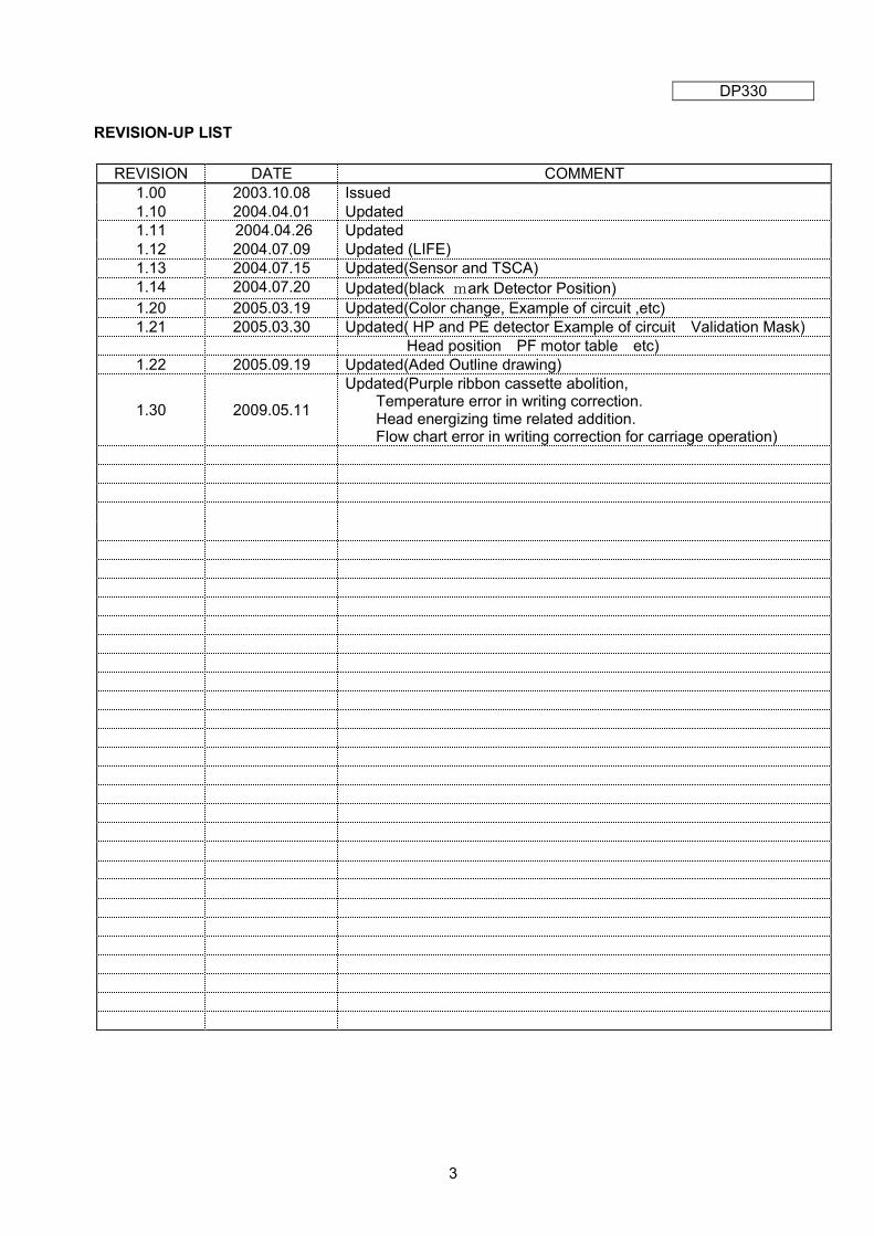
REVISION-UP LIST
REVISION DATE COMMENT
1.00 2003.10.08 Issued
1.10 2004.04.01 Updated
1.11 2004.04.26 Updated
1.12 2004.07.09 Updated (LIFE)
1.13 2004.07.15 Updated(Sensor and TSCA)
1.14 2004.07.20 Updated(black mark Detector Position)
1.20 2005.03.19 Updated(Color change, Example of circuit ,etc)
1.21 2005.03.30 Updated( HP and PE detector Example of circuit Validation Mask)
Head position PF motor table etc)
1.22 2005.09.19 Updated(Aded Outline drawing)
1.30 2009.05.11
Updated(Purple ribbon cassette abolition, Temperature error in writing correction. Head energizing time related addition. Flow chart error in writing correction for carriage operation)
4
REVISION-UP HISTORY
PAGE ITEM CHANGE POINT

5
TABLE OF CONTENTS
1. INTRODUCTION ------------------------------------------------------------------ 7
2. GENERAL SPECIFICATIONS --------------------------------------------------- 8-10
2.1 Printing Method -------------------------------------------------------- 8
2.2 Printing Direction ------------------------------------------------------ 8
2.3 Printing Format --------------------------------------------------------- 8
2.4 Printing Speed -------------------------------------------------------- 8
2.5 Paper Feed ------------------------------------------------------------- 8
2.6 Paper --------------------------------------------------------------------- 8
2.7 Inking --------------------------------------------------------------------- 8
2.8 Power Voltage ---------------------------------------------------------- 9
2.9 Connecting Method --------------------------------------------------- 9
2.10 Printer Installation angle --------------------------------------------- 9
2.11 Environmental Conditions ------------------------------------------- 9
2.12 Environmental Conditions For Storage -------------------------- 10
2.13 Reliability ---------------------------------------------------------------- 10
2.14 Options ------------------------------------------------------------------- 10
2.15 Outer Diameter --------------------------------------------------------- 10
2.16 Weight -------------------------------------------------------------------- 10
2.17 TSCA ---------------------------------------------------------------------- 10
2.18 Insulation Resistance -------------------------------------------------- 10
3. DETAILED SPECIFICATIONS -------------------------------------------------- 11-39
3.1 Paper ----------------------------------------------------------------------- 11
3.2 Print Format -------------------------------------------------------------- 13
3.3 Print Solenoid ----------------------------------------------------------- 14
3.4 Home Position Detector ------------------------------------------------- 20
3.5 Carriage Motor ---------------------------------------------------------- 23
3.6 Paper end detector ---------------------------------------------------------26
3.7 Paper Feed Motor ----------------------------------------------------- 28
3.8 Validation Printer ------------------------------------------------------- 30
3.9 Ribbon Cassette -------------------------------------------------------- 31
3.10 Connector ----------------------------------------------------------------- 32
3.11 Options ------------------------------------------------------------------- 33
3.12 Timing Chart -------------------------------------------------------------- 37

6
4. REMARKS -------------------------------------------------------------------------- 38
4.1 Detection of Abnormal Conditions ---------------------------------- 38
4.2 Handling Ribbon Cartridge --------------------------------------------- 38
4.3 Re-winder ---------------------------------------------------------------- 38
4.4 Appearance of Stamping Plate ------------------------------------- 38
4.5 Precaution for Printer Setting up -------------------------------------- 38
4.6 Printer Usage Precaution --------------------------------------------- 38
4.7 Prohibitive Matters ----------------------------------------------------- 38
5. OUTER DIMENSION ------------------------------------------------------------- 39~40
6. PACKING ------------------------------------------------------------------------------ 41
7. PRINT QUALITY STANDARD -------------------------------------------------- 42~43
NOTE: Information in this document is subject to change without notice
due to technical design improvement. It is recommended to contact
us to obtain updated specification for your application.

7
1. INTRODUCTION
The DP330 printer has the printing mechanism which is characterized by logical seek printing,
mounting the small size dot matrix print head which assures high speed printing, high reliability and
Low price. The printer is driven by two stepping motors and is capable of the right / leftward scanning
of the print head, paper feeding and changeover of the two color ribbons (red/black).
DP330 - * F * *
Black mark Detector
Main PCB
Paper Feed System
Ribbon Casette
Paper width
.
Friction system (fixed) F
76 mm 3
With Volume V
Without Volume N
Detector position, Right B B
Detector position, Right A A
Detector position, Right C C
Detector position, Left B K
Detector position, Left A J
Detector position, Left C L
No Detector N
Black Ribbon
B
Red/Black Ribbon D
8
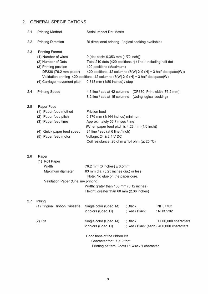
2. GENERAL SPECIFICATIONS
2.1 Printing Method Serial Impact Dot Matrix
2.2 Printing Direction Bi-directional printing(logical seeking available)
2.3 Printing Format
(1) Number of wires 9 (dot-pitch: 0.353 mm (1/72 inch))
(2) Number of Dots Total 210 dots (420 positions *) / line * including half dot
(3) Printing position 420 positions (Maximum)
DP330 (76.2 mm paper) 420 positions, 42 columns (7(W) X 9 (H) + 3 half-dot space(W))
Validation printing 420 positions, 42 columns (7(W) X 9 (H) + 3 half-dot space(W)
(4) Carriage movement pitch 0.318 mm (1/80 inches) / step
2.4 Printing Speed 4.3 line / sec at 42 columns (DP330, Print width: 76.2 mm)
8.2 line / sec at 15 columns (Using logical seeking)
2.5 Paper Feed
(1) Paper feed method Friction feed
(2) Paper feed pitch 0.176 mm (1/144 inches) minimum
(3) Paper feed time Approximately 56.7 msec / line
(When paper feed pitch is 4.23 mm (1/6 inch))
(4) Quick paper feed speed 34 line / sec (at 6 line / inch)
(5) Paper feed motor Voltage: 24 ± 2.4 V DC
Coil resistance: 20 ohm ± 1.4 ohm (at 25 °C)
2.6 Paper
(1) Roll Paper
Width 76.2 mm (3 inches) ± 0.5mm
Maximum diameter 83 mm dia. (3.25 inches dia.) or less
Note: No glue on the paper core.
Validation Paper (One line printing)
Width: grater than 130 mm (5.12 inches)
Height: greater than 60 mm (2.36 inches)
2.7 Inking
(1) Original Ribbon Cassette Single color (Spec. M) ; Black : NH37703
2 colors (Spec. D) ; Red / Black : NH37702
(2) Life Single color (Spec. M) ; Black : 1,000,000 characters
2 colors (Spec. D) ; Red / Black (each): 400,000 characters
Conditions of the ribbon life
Character font; 7 X 9 font
Printing pattern; 2dots / 1 wire / 1 character

9
2.8 Power voltage
(1) Printer power voltage: 24 ± 2.4 V DC
Note:
1.Voltage specification apply to the print head, carriage motor and paper feed motor
2. The same power supply should be used for the above parts.
3. The voltage loss in the energizing circuitry (combined line loss and driver saturation voltage)
must be as follows.
Print head: Less than 1.5 V DC
Others: Less than 1.0 V DC
4.The above voltage should be applied, when all nine pins are driven simultaneously.
(2) Detect input voltage: 5 ± 0.25 V DC
Note:
Applies to the home position detector, paper end detector ,print head temperature Sensing
element, optional black mark detector .
2.9 Connecting Method
(1) Printer side FFC or FPC connector (Type; 27FE-ST)
(2) User side 1.25 mm pitch FFC or FPC
(Width; 35 mm (1.38 inches), thickness; 0.3 mm (0.012 inches),
including reinforcement plate)
2.10 Printer Installation Angle The printer must be installed horizontally, but it can be tiled by
as much as ± 20 degrees.
2.11 Environmental Conditions
(1) Operating temperature 0 - 50 °C (32 - 122 °F)
(2) Operating humidity 10 - 90 % RH (without condensation)
Humidity 90 (%)
50
10
0 35 50 (°C) Temperature
10
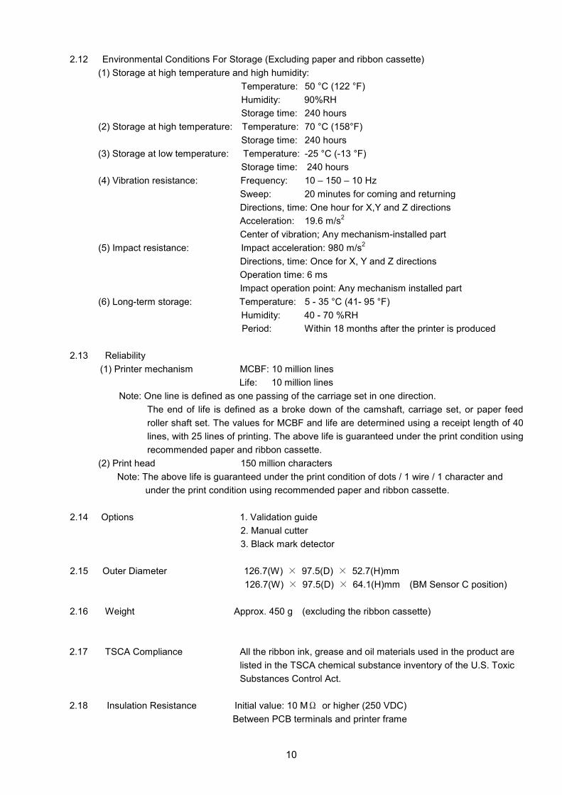
2.12 Environmental Conditions For Storage (Excluding paper and ribbon cassette)
(1) Storage at high temperature and high humidity:
Temperature: 50 °C (122 °F)
Humidity: 90%RH
Storage time: 240 hours
(2) Storage at high temperature: Temperature: 70 °C (158°F)
Storage time: 240 hours
(3) Storage at low temperature: Temperature: -25 °C (-13 °F)
Storage time: 240 hours
(4) Vibration resistance: Frequency: 10 – 150 – 10 Hz
Sweep: 20 minutes for coming and returning
Directions, time: One hour for X,Y and Z directions
Acceleration: 19.6 m/s2
Center of vibration; Any mechanism-installed part
(5) Impact resistance: Impact acceleration: 980 m/s2
Directions, time: Once for X, Y and Z directions
Operation time: 6 ms
Impact operation point: Any mechanism installed part
(6) Long-term storage: Temperature: 5 - 35 °C (41- 95 °F)
Humidity: 40 - 70 %RH
Period: Within 18 months after the printer is produced
2.13 Reliability
(1) Printer mechanism MCBF: 10 million lines
Life: 10 million lines
Note: One line is defined as one passing of the carriage set in one direction.
The end of life is defined as a broke down of the camshaft, carriage set, or paper feed
roller shaft set. The values for MCBF and life are determined using a receipt length of 40
lines, with 25 lines of printing. The above life is guaranteed under the print condition using
recommended paper and ribbon cassette.
(2) Print head 150 million characters
Note: The above life is guaranteed under the print condition of dots / 1 wire / 1 character and
under the print condition using recommended paper and ribbon cassette.
2.14 Options 1. Validation guide
2. Manual cutter
3. Black mark detector
2.15 Outer Diameter 126.7(W) × 97.5(D) × 52.7(H)mm
126.7(W) × 97.5(D) × 64.1(H)mm (BM Sensor C position)
2.16 Weight Approx. 450 g (excluding the ribbon cassette)
2.17 TSCA Compliance All the ribbon ink, grease and oil materials used in the product are
listed in the TSCA chemical substance inventory of the U.S. Toxic
Substances Control Act.
2.18 Insulation Resistance Initial value: 10 MΩ or higher (250 VDC)
Between PCB terminals and printer frame
11
3. DETAILED SPECIFICATIONS 3.1 Paper
The printer paper is supplied by the user. Please use only paper that fulfills the following
requirements to assure good print quality and stable paper feed.
(1) Roll paper
DP330 (paper width 76 mm)
a) Normal paper
Paper width 76.2 ± 0.5(3 ± 1/36 inches)
Outer diameter of roll 83 mm dia. (3.25 inches) or less
(Maximum inside diameter of the paper roll core must be
10 +2/-0 mm (0.394 +0.078/-0 inches))
Paper thickness 0.06 – 0.085 mm
Paper weight 52.3 - 64.0 g/m2(JIS P8124)(14 – 17 lb)
(45 - 55 kg / 1000 sheets / 788mm x 1091 mm)
Recommended paper Oji resister paper
b) Pressure-sensitive paper (2 plat non-carbon paper (1P Original + 1P copy))
Paper thickness 0.05 – 0.08 mm / 1P
(Note: total thickness is less than 0.16 mm)
Recommended paper Mitsubishi-Seishi NCR super (Blue)
(2) Validation paper Greater than 130 mm (5.12”) (W) x 60 mm (2.36”) (H)
Paper thickness 0.085 – 0.1 mm
Total thickness of paper Less than 0.25 mm (0.0098 inches) (Including roll paper)
Total number of paper 3 (Maximum, Including roll paper)
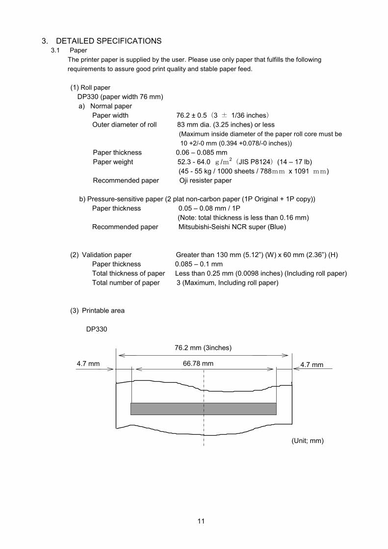
(3) Printable area
DP330
(Unit; mm)
66.78 mm
76.2 mm (3inches)
4.7 mm
4.7 mm
12
(4) Note
1) Conditions on inside end of roll paper (with or without a core)
a) No fold is allowed. The paper should be wound so that the paper edge goes along the
internal circumference.
b) No folding is allowed.
c) The inside end should not be glued to the core. (When a core exists)
d) The upper and lower layers of paper should not be glued to each other.
2) Roll paper sag
When pressure-sensitive roll paper is used, the difference in diameter between the upper
and lower sheets generates slack in the upper sheet. The shape of the case around the
roll paper holder should be designed so that it allows some slack in the upper sheet.
Besides this, when a paper take-up device is employed, be careful of its position to
prevent the upper sheet slack from being taken up by the device.
13
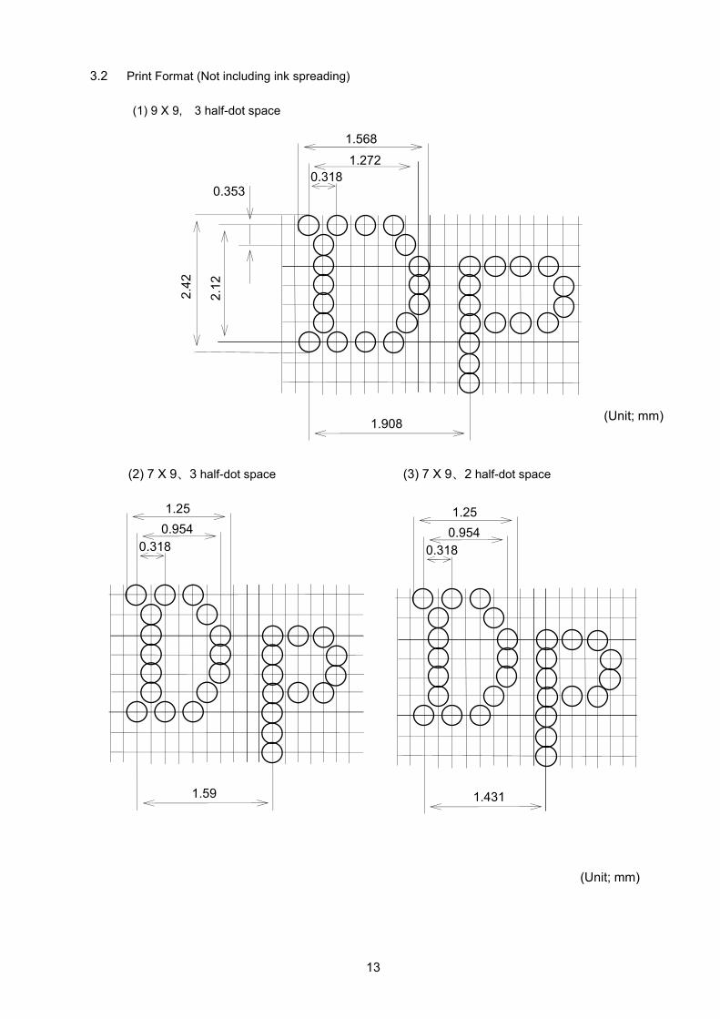
3.2 Print Format (Not including ink spreading)
(1) 9 X 9, 3 half-dot space
(2) 7 X 9、3 half-dot space (3) 7 X 9、2 half-dot space
1.25
0.954
0.318
1.59
(Unit; mm)
1.25
0.954
0.318
1.431
(Unit; mm)
1.568
1.272
0.318 2
.42
2.1
2
1.908
0.353
14
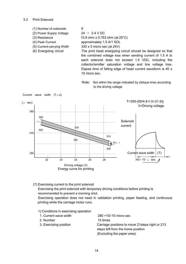
3.3 Print Solenoid
(1) Number of solenoids 9
(2) Power Supply Voltage 24 ± 2.4 V DC
(3) Resistance 10.9 ohm ± 0.763 ohm (at 25°C)
(4) Peak Current approximately 1.5 A/1 SOL
(5) Current-carrying Width 330 ± 5 micro sec (at 24V)
(6) Energizing circuit The print head energizing circuit should be designed so that
the combined voltage loss when sending current of 1.5 A to
each solenoid does not exceed 1.5 VDC, including the
collector/emitter saturation voltage and line voltage loss.
Elapse time of falling edge of head current waveform is 40 ±
10 micro sec.
Note: Set within the range indicated by oblique lines according
to the driving voltage
(7) Exercising current to the print solenoid
Exercising the print solenoid with temporary driving conditions before printing is
recommended to prevent a morning shot.
Exercising operation does not need in validation printing, paper feeding, and continuous
printing while the carriage motor runs.
1) Conditions in exercising operation
1. Current wave width 280 +10/-10 micro sec
2. Number 10 times
3. Exercising position Carriage positions to move 21steps right or 213
steps left from the home position
(Excluding the paper area)
40±10 μ sec
Solenoid
current
Current wave width (T)
Current wave width (Tμs)
Driving voltage (V)
Energy curve for printing
380
330
280
335
10μs 325
24 26 25 23 22
(μ sec)
350
310
300
360
T=355-{50/4.8*(V-21.6)}
V=Driving voltage

15
Approx.1.5A
⊿t Note 1
833(+40/-0)μsec Note 2
330 ±5 μsec (at 24V)
416.5μsec +⊿t
(8) Driving Timing
Note 1) Print waiting time (⊿t) which is passed from time of carriage motor phase change to time
of print start must be defined in order to adjust the vertical dot alignment that is formed by
the print head in either direction of the carriage movement. It is recommended that ⊿t
variable range is ±500 μsec and minimum adjustable unit is 17 μsec. Uni-directional
print is recommended for graphic or double height printing, otherwise, print dot alignment
in vertical may be inaccurate. To print out more precisely in both directions of the carriage
movement, it is also recommended that a thermistor which detects an atmosphere
temperature is installed on a circuit board of a user side, and print waiting time (⊿t) is
revised according to the printing atmosphere temperature.
Note 2) Phase change timing cycle is minimum 833 μsec.
Note 3) Half dot print is defined as the half of head trigger signal pulse (min. 416.5 + ⊿t)
Note 4) Continuous full and half dot print performed by the same wire is prohibited.
Note 5) Elapse time of falling edge of head current waveform is 40 ± 10 μ sec.
Note 6) The above specification of drive timing except for the head current waveform
should be designed by a user of this printer.
Note 7) To adjust the print waiting time (⊿t) whenever a user of this printer like is recommended.
Carriage motor
Phase A
Carriage motor
Phase B
Head trigger pulse
Head ON timer
Head current
waveform
Note 3
±500 μsec
(Recommended range)

16
(9) Energy consumption
No Item Value
1
Standard average input energy (24 VDC at room temperature)
Approximately 6.8mJ / 1 dot
(Current carrying width: 330μs)
2
Maximum input energy (26.4 VDC at 0 °C (32 °F))
Approximately 8.8mJ / 1 dot
(Current carrying width: 310μs)
3 Power calculation method (Input energy) X (Number of printing dots) (Printing time)
4
Average power for printing character “K” as shown below
Approximately 25.4 W (6.8mJ X 14 dots)/(0.4165 X 9 timing)
5
Peak current (Worst case)
Approximately10.0 A
(24VDC at room temperature, when nine wires are driven at the same time)
Approximately13.5 A
(0 ℃, 26.4VDC, when nine wires are driven at the
same time)
Note: Voltage should not drop below 21.6 VDC even if when nine wires are driven at the
same time.
(10) Printing Duty
Calculate the number of the dots from the printing, and set it up in less than allowable duty
line which shows total dot / one-second in the figure.
Allowable characters (cha/line)
= see upper (A) / Average No. of dots at 1 character (B) / printing speed (*LPS)
(dot / sec) (dot / cha) (line / sec)
Ambient temperature
25 °C
1170 dots 1080 dots
990 dots
780 dots
720 dots
660 dots
26.4V 24V 21.6V Ambient temperature
50 °C

17
(11) Temperature sensing element control (thermistor)
The print head temperature detect thermistor is built in the print head to prevent burnout,
smoke emission and fire hazard.
1) Use conditions
Use the temperature-sensing element within the range of the print duty as shown.
(Head temperature is less than 120 °C (248 °F)
The values of the temperature-sensing element should be checked between unprinted areas
after one line print is completed. When the thermistor value becomes over 16.43 k ohm
(inside print head temperature: 140 °C (284 °F)), the head coil current is adjusted to the
specified duty value.
Thermistor resistance is 10 ± 0.1 k ohms at 25 °C.
2) Thermistor
LP73 2B 103J5000 (KOA)or equivalent
18
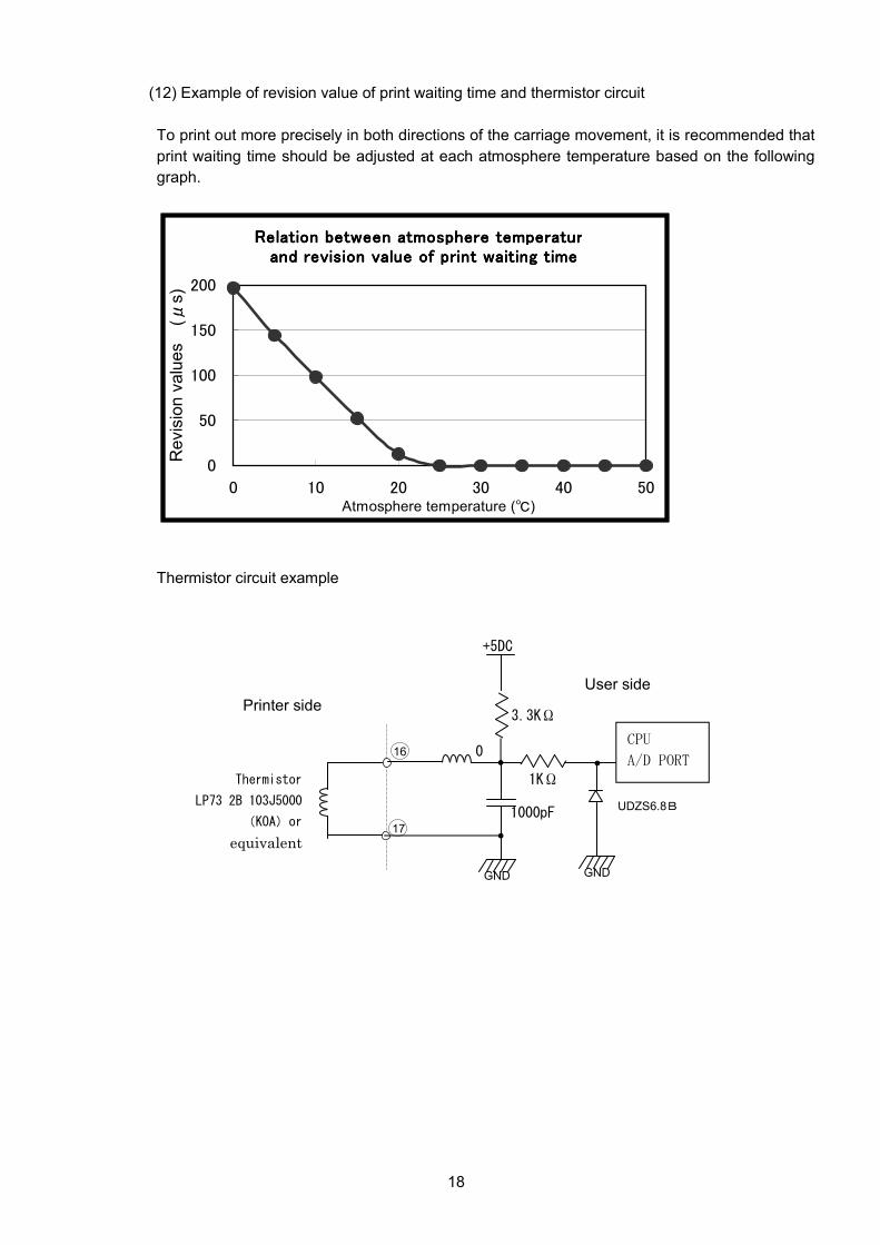
(12) Example of revision value of print waiting time and thermistor circuit
To print out more precisely in both directions of the carriage movement, it is recommended that
print waiting time should be adjusted at each atmosphere temperature based on the following
graph.
Relation between atmosphere temperatureRelation between atmosphere temperatureRelation between atmosphere temperatureRelation between atmosphere temperatureand revision value of print waiting timeand revision value of print waiting timeand revision value of print waiting timeand revision value of print waiting time
0
50
100
150
200
0 10 20 30 40 50Atmosphere temperature (℃)
Revis
ion v
alu
es
( μs)
Thermistor circuit example
16
17
0
GND
+5DC
1000pF
3.3KΩ
1KΩ
CPU
A/D PORT
GND
Thermistor
LP73 2B 103J5000
(KOA)or
equivalent
UDZS6.8B
Printer side
User side
19
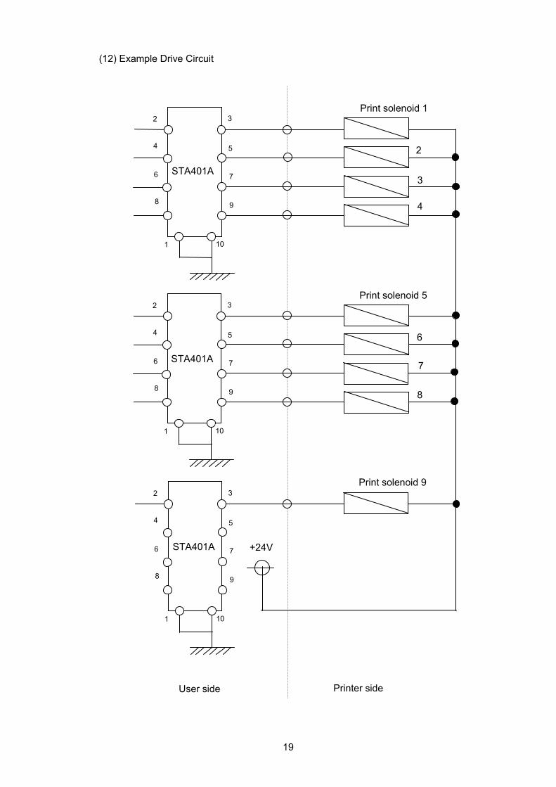
(12) Example Drive Circuit
2 3
4 5
6 7
9 8
10 1
2 3
4 5
6 7
9 8
10 1
2 3
4 5
6 7
9 8
10 1
Print solenoid 1
2
STA401A 3
4
Print solenoid 5
6
STA401A 7
8
Print solenoid 9
+24V STA401A
User side Printer side
20
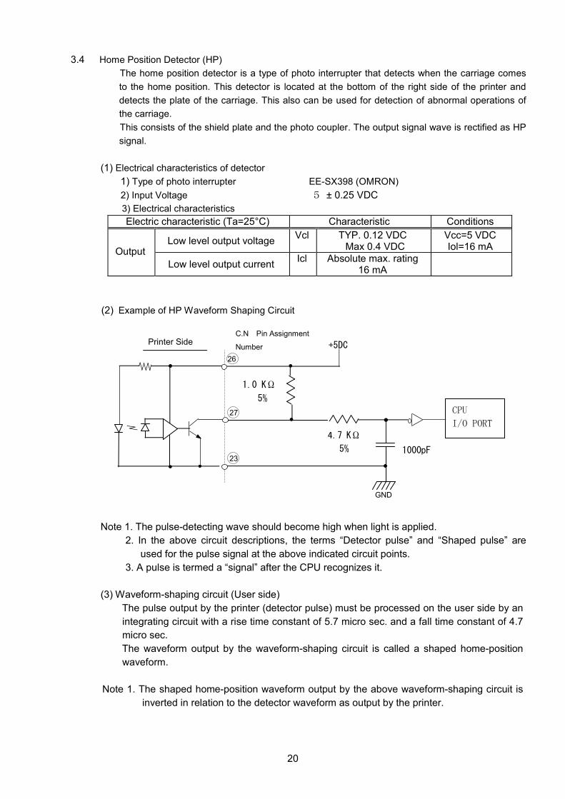
3.4 Home Position Detector (HP)
The home position detector is a type of photo interrupter that detects when the carriage comes
to the home position. This detector is located at the bottom of the right side of the printer and
detects the plate of the carriage. This also can be used for detection of abnormal operations of
the carriage.
This consists of the shield plate and the photo coupler. The output signal wave is rectified as HP
signal.
(1) Electrical characteristics of detector
1) Type of photo interrupter EE-SX398 (OMRON)
2) Input Voltage 5 ± 0.25 VDC
3) Electrical characteristics
Electric characteristic (Ta=25°C) Characteristic Conditions
Low level output voltage Vcl TYP. 0.12 VDC
Max 0.4 VDC Vcc=5 VDC Iol=16 mA
Output
Low level output current Icl Absolute max. rating
16 mA
(2) Example of HP Waveform Shaping Circuit
Note 1. The pulse-detecting wave should become high when light is applied.
2. In the above circuit descriptions, the terms “Detector pulse” and “Shaped pulse” are
used for the pulse signal at the above indicated circuit points.
3. A pulse is termed a “signal” after the CPU recognizes it.
(3) Waveform-shaping circuit (User side)
The pulse output by the printer (detector pulse) must be processed on the user side by an
integrating circuit with a rise time constant of 5.7 micro sec. and a fall time constant of 4.7
micro sec.
The waveform output by the waveform-shaping circuit is called a shaped home-position
waveform.
Note 1. The shaped home-position waveform output by the above waveform-shaping circuit is
inverted in relation to the detector waveform as output by the printer.
4.7 KΩ
5%
1.0 KΩ
5%
Printer Side
C.N Pin Assignment
Number
CPU
I/O PORT
26
27
23
GND
1000pF
+5DC

21
Noise
Tn Tn +1 Noise
Detected Signal
Reading timing 15±5micro sec
(4) Output signal level by the shaped HP waveform point
Signal level
Carriage position Output signal
In home position High
Out of home position Low
(6) Relation of HP and Carriage movement
(6) Detector Signal judgment
Read the detector signal when the signal level changed (falling or rising). After 15 ± 5 micro sec
from detected edge, the detector signal should be read again.
Each signal judgment is only considered to be possible when the results of both cases match.
If the two results do not match, repeat the procedure above.
GND
+5V
42 steps (2 colors, spec. D)
Note: including 21 steps for color change
21 steps (Single color, spec. M)
226 steps (2 colors, spec. D) Note; including 13 steps for color change
213 steps (Single color, spec. M)
Low
High
HP Wave form
HP
Left side of carriage Right side of carriage
22
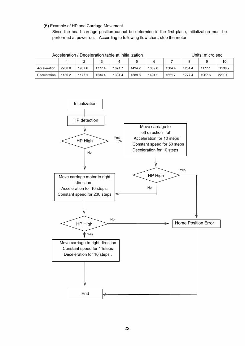
(6) Example of HP and Carriage Movement
Since the head carriage position cannot be determine in the first place, initialization must be
performed at power on. According to following flow chart, stop the motor
Acceleration / Deceleration table at initialization Units: micro sec
1 2 3 4 5 6 7 8 9 10
Acceleration 2200.0 1967.6 1777.4 1621.7 1494.2 1389.8 1304.4 1234.4 1177.1 1130.2
Deceleration 1130.2 1177.1 1234.4 1304.4 1389.8 1494.2 1621.7 1777.4 1967.6 2200.0
Initialization
HP detection
End
Move carriage to right direction
Constant speed for 11steps
Deceleration for 10 steps .
Yes HP High
No
Yes
Move carriage to
left direction at
Acceleration for 10 steps
Constant speed for 50 steps
Deceleration for 10 steps
No
No Home Position Error
Yes
HP High
HP High
Move carriage motor to right
direction .
Acceleration for 10 steps,
Constant speed for 230 steps

23
3.5 Carriage Motor
The movement of the carriage (forward and reverse) is by controlling the carriage drive motor.
(1) Specification
a) Type 4-phase 20-pole PM type stepping motor
b) Control method Constant current chopper driving with 2-phase excitation
c) Coil resistance 17.5 ± 1.75Ω(at 25°C, 1 phase)
Note: Stepping motor does the movement of carriage and a roll paper feed.
(2) Power supply voltage 24 ± 2.4 V DC
(3) Current consumption
(a)Driving in accelerating and decelerating 350mA
(b)Driving at constant speed 350mA
(c)Low excitement time (hold time) 106mA
(d)high excitement time 350mA
Note: Don't supply current to the same phase continuously for more than one second
except for hold time.
(4) Maximum drive frequency 1200 pps (pulses per second)
Note: Minimum period of pulses is 0.833 msec.
(5) Circuit
(6) Drive sequence
Movement in the direction of right to left
H: high level L: low level Step Phase
1 2 3 4
B phase H L L H
A phase L L H H
B phase L H H L
A phase H H L L
Movement in the direction of left to right
H: high level L: low level Step Phase
1 2 3 4
B phase H L L H
A phase H H L L
B phase L H H L
A phase L L H H
A
A B
B
Motor

24
(7) Carriage motor slow up/down control
It should control open loop, and the control of carriage motor does switching in accordance
with the switching time-table
a) Slow up
Step 1 2 3 4 5 6 7 8 9 10 11 12 13
Const.
Switching time
(ms±0.05) 2.80 1.76 1.51 1.32 1.17 1.07 0.99 0.94 0.91 0.86 0.83 0.83 0.83
Pulse
(PPS) 455 568 662 758 855 935 1010 1064 1099 1163 1200 1200 1200
b)Slow down
Step 1 Const.
2 3 4 5 6 7 8 9 10 11 12 13
Switching time
(ms±0.05) 0.83 0.88 0.93 1.02 1.09 1.21 1.31 1.45 1.61 1.83 2.13 2.49 3.20
Pulse
(PPS) 1200 1136 1078 978 914 825 765 690 619 547 468 402 313
(8) Minimum drive amount of the carriage motor
The carriage should move from left at least 72 steps to right to feed ribbon before the
printing is started, because the ribbon feed is performed while the carriage is moved. The
carriage motor can be stopped before reaching the minimum drive amount of the carriage
motor, when the carriage is moved without printing
(9)Constant speed
When moving less than 24 steps ,perform phase switching at a Low speed of 357.1PPS
(2.8msec)
(10) Step number
1) Single color (spec. M)
Area
Step number 12 210 12
HP waveform
2) 2 colors (spec. D)
Area
Step number 13 12 210 12 21
HP waveform
Driving In
accelerating and
decelerating
Driving at
constant
speed
Driving In
accelerating and
decelerating
Driving In
accelerating and
decelerating
Driving at
constant
speed
Driving In
accelerating and
decelerating
Ribbon change
(Black =>Red)
Ribbon change
(Red=>Black)
High
Low9
High
Low9
25
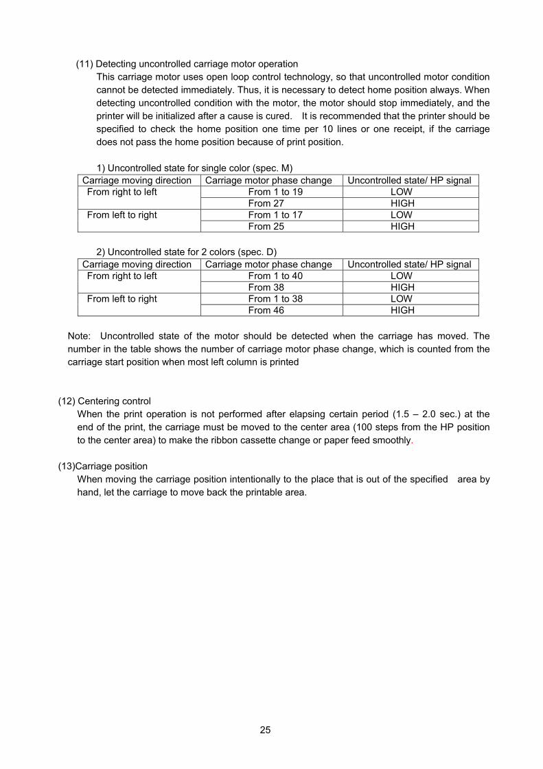
(11) Detecting uncontrolled carriage motor operation
This carriage motor uses open loop control technology, so that uncontrolled motor condition
cannot be detected immediately. Thus, it is necessary to detect home position always. When
detecting uncontrolled condition with the motor, the motor should stop immediately, and the
printer will be initialized after a cause is cured. It is recommended that the printer should be
specified to check the home position one time per 10 lines or one receipt, if the carriage
does not pass the home position because of print position.
1) Uncontrolled state for single color (spec. M)
Carriage moving direction Carriage motor phase change Uncontrolled state/ HP signal
From 1 to 19 LOW From right to left
From 27 HIGH
From 1 to 17 LOW From left to right
From 25 HIGH
2) Uncontrolled state for 2 colors (spec. D)
Carriage moving direction Carriage motor phase change Uncontrolled state/ HP signal
From 1 to 40 LOW From right to left
From 38 HIGH
From 1 to 38 LOW From left to right
From 46 HIGH
Note: Uncontrolled state of the motor should be detected when the carriage has moved. The
number in the table shows the number of carriage motor phase change, which is counted from the
carriage start position when most left column is printed
(12) Centering control
When the print operation is not performed after elapsing certain period (1.5 – 2.0 sec.) at the
end of the print, the carriage must be moved to the center area (100 steps from the HP position
to the center area) to make the ribbon cassette change or paper feed smoothly.
(13)Carriage position
When moving the carriage position intentionally to the place that is out of the specified area by
hand, let the carriage to move back the printable area.
26
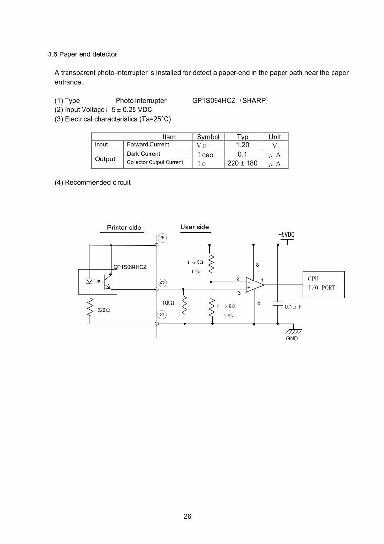
3.6 Paper end detector
A transparent photo-interrupter is installed for detect a paper-end in the paper path near the paper
entrance.
(1) Type Photo interrupter GP1S094HCZ(SHARP)
(2) Input Voltage; 5 ± 0.25 VDC
(3) Electrical characteristics (Ta=25°C)
Item Symbol Typ Unit Input Forward Current VF 1.20 V
Dark Current Iceo 0.1 μA Output
Collector Output Current Ic 220 ± 180 μA
(4) Recommended circuit
23
26
25 2
3
4
8
+5VDC
CPU
I/O PORT
GP1S094HCZ
220Ω
1
+ -
6.2KΩ
1%
Printer side
10KΩ
16KΩ
1%
0.1μF
GND
User side

27
(5) Detector position
Platen
Approx. 27.15
(Paper length)
Approx. 26.15
(Paper length)
Print Center
Unit; mm
Paper
entrance
direction
Paper exit
direction
Friction roller
● ;Paper end detector
Position

28
3.7 Paper Feed Motor
Paper is fed by controlling the paper feed motor.
(1) Specification
a) Type 4 phases 20 pole PM type stepping motor
b) Control method Constant current chopper driving with 2-phase excitation
c) Power supply voltage 20 ± 1.4 ohm (25 °C, 1 phase)
(2) Coil resistance 24 ± 2.4 V DC
(3) Current consumption
a) Driving in accelerating and deceleration 300±21 mA (2 phase excitation)
b) Driving at constant speed 300±21 mA (2 phase excitation)
c) Low excitement time (hold time) 90±20 mA (2 phase excitation)
d) High excitement time 300±21 mA (2 phase excitation)
Note:Don’t supply current to the same phase continuously for more than
one second except for hold time.
(4) Maximum drive frequency 826 pps (pulses per second)
Note: Minimum period of pulses is 1.21 msec.
(5) Circuit
(7) Drive sequence
1) Forward direction H: High level L: Low level Step Phase
1 2 3 4
B phase H L L H
A phase H H L L
B phase L H H L
A phase L L H H
2) Reverse direction H: High level L: Low level Step Phase
1 2 3 4
B phase H L L H
A phase L L H H
B phase L H H L
A phase H H L L
A
A
B
B
Motor
29
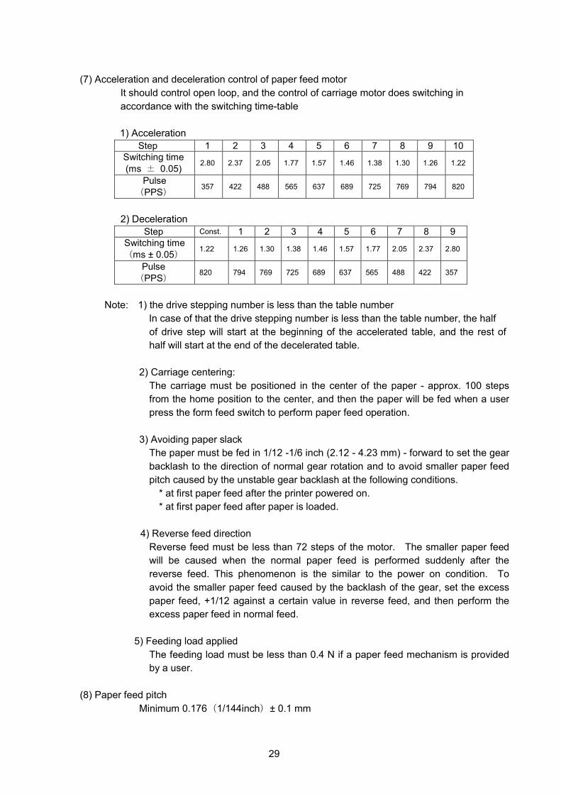
(7) Acceleration and deceleration control of paper feed motor
It should control open loop, and the control of carriage motor does switching in
accordance with the switching time-table
1) Acceleration
Step 1 2 3 4 5 6 7 8 9 10
Switching time
(ms ± 0.05) 2.80 2.37 2.05 1.77 1.57 1.46 1.38 1.30 1.26 1.22
Pulse
(PPS) 357 422 488 565 637 689 725 769 794 820
2) Deceleration
Step Const. 1 2 3 4 5 6 7 8 9
Switching time
(ms ± 0.05) 1.22 1.26 1.30 1.38 1.46 1.57 1.77 2.05 2.37 2.80
Pulse
(PPS) 820 794 769 725 689 637 565 488 422 357
Note: 1) the drive stepping number is less than the table number
In case of that the drive stepping number is less than the table number, the half
of drive step will start at the beginning of the accelerated table, and the rest of
half will start at the end of the decelerated table.
2) Carriage centering:
The carriage must be positioned in the center of the paper - approx. 100 steps
from the home position to the center, and then the paper will be fed when a user
press the form feed switch to perform paper feed operation.
3) Avoiding paper slack
The paper must be fed in 1/12 -1/6 inch (2.12 - 4.23 mm) - forward to set the gear
backlash to the direction of normal gear rotation and to avoid smaller paper feed
pitch caused by the unstable gear backlash at the following conditions.
* at first paper feed after the printer powered on.
* at first paper feed after paper is loaded.
4) Reverse feed direction
Reverse feed must be less than 72 steps of the motor. The smaller paper feed
will be caused when the normal paper feed is performed suddenly after the
reverse feed. This phenomenon is the similar to the power on condition. To
avoid the smaller paper feed caused by the backlash of the gear, set the excess
paper feed, +1/12 against a certain value in reverse feed, and then perform the
excess paper feed in normal feed.
5) Feeding load applied
The feeding load must be less than 0.4 N if a paper feed mechanism is provided
by a user.
(8) Paper feed pitch
Minimum 0.176(1/144inch)± 0.1 mm
30
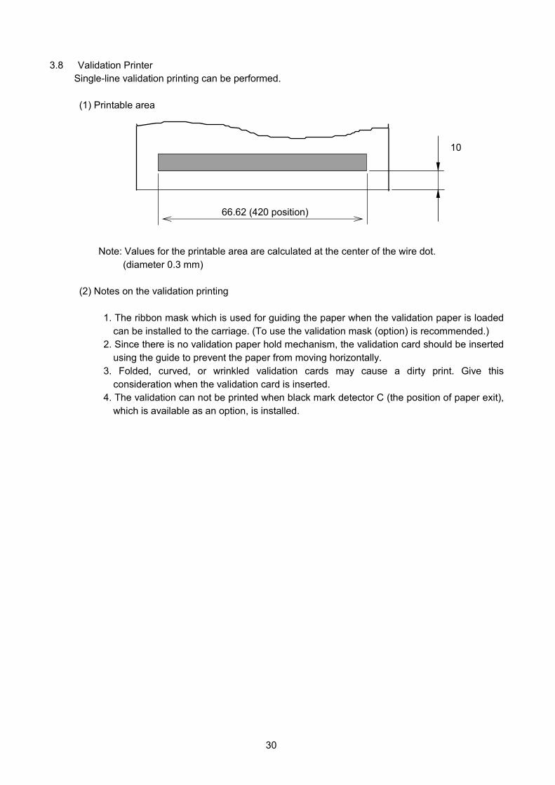
3.8 Validation Printer
Single-line validation printing can be performed.
(1) Printable area
Note: Values for the printable area are calculated at the center of the wire dot.
(diameter 0.3 mm)
(2) Notes on the validation printing
1. The ribbon mask which is used for guiding the paper when the validation paper is loaded
can be installed to the carriage. (To use the validation mask (option) is recommended.)
2. Since there is no validation paper hold mechanism, the validation card should be inserted
using the guide to prevent the paper from moving horizontally.
3. Folded, curved, or wrinkled validation cards may cause a dirty print. Give this
consideration when the validation card is inserted.
4. The validation can not be printed when black mark detector C (the position of paper exit),
which is available as an option, is installed.
66.62 (420 position)
10
31
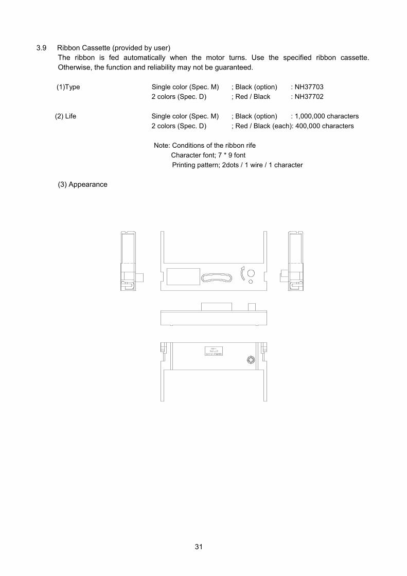
3.9 Ribbon Cassette (provided by user)
The ribbon is fed automatically when the motor turns. Use the specified ribbon cassette.
Otherwise, the function and reliability may not be guaranteed.
(1)Type Single color (Spec. M) ; Black (option) : NH37703
2 colors (Spec. D) ; Red / Black : NH37702
(2) Life Single color (Spec. M) ; Black (option) : 1,000,000 characters
2 colors (Spec. D) ; Red / Black (each): 400,000 characters
Note: Conditions of the ribbon rife
Character font; 7 * 9 font
Printing pattern; 2dots / 1 wire / 1 character
(3) Appearance
32
Supporting Tape
7.7
5 M
IN
0.3±0.05 0.8±0..03 1.25±0.15
1.25±0.15 32.5±0.05
35±0.1
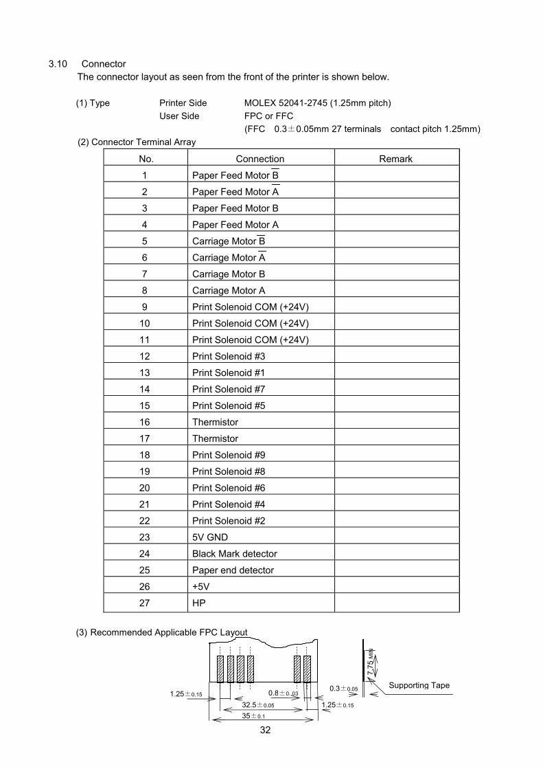
3.10 Connector
The connector layout as seen from the front of the printer is shown below.
(1) Type Printer Side MOLEX 52041-2745 (1.25mm pitch)
User Side FPC or FFC
(FFC 0.3±0.05mm 27 terminals contact pitch 1.25mm)
(2) Connector Terminal Array
No. Connection Remark
1 Paper Feed Motor B
2 Paper Feed Motor A
3 Paper Feed Motor B
4 Paper Feed Motor A
5 Carriage Motor B
6 Carriage Motor A
7 Carriage Motor B
8 Carriage Motor A
9 Print Solenoid COM (+24V)
10 Print Solenoid COM (+24V)
11 Print Solenoid COM (+24V)
12 Print Solenoid #3
13 Print Solenoid #1
14 Print Solenoid #7
15 Print Solenoid #5
16 Thermistor
17 Thermistor
18 Print Solenoid #9
19 Print Solenoid #8
20 Print Solenoid #6
21 Print Solenoid #4
22 Print Solenoid #2
23 5V GND
24 Black Mark detector
25 Paper end detector
26 +5V
27 HP
(3) Recommended Applicable FPC Layout
33
3.11 Options
3.11.1 Validation guide
The validation guide, which guides the validation when it is inserted, can be installed in the
printer main frame.
3.11.2 Manual cutter
The manual cutter for cutting paper roll can be installed in the printer main frame.
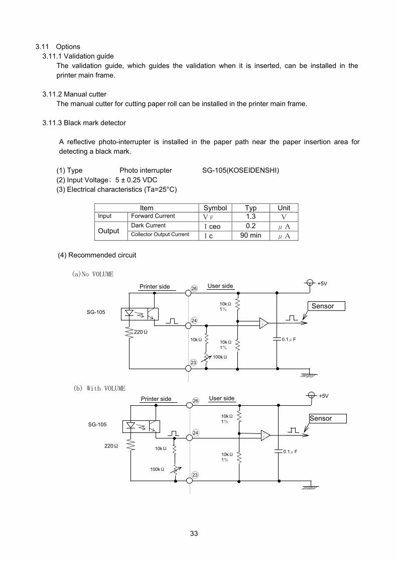
3.11.3 Black mark detector
A reflective photo-interrupter is installed in the paper path near the paper insertion area for
detecting a black mark.
(1) Type Photo interrupter SG-105(KOSEIDENSHI)
(2) Input Voltage; 5 ± 0.25 VDC
(3) Electrical characteristics (Ta=25°C)
Item Symbol Typ Unit Input Forward Current VF 1.3 V
Dark Current Iceo 0.2 μA Output
Collector Output Current Ic 90 min μA
(4) Recommended circuit
(a)No VOLUME
(b) With VOLUME
23
24
26
0.1μF
+5V
10kΩ 220Ω
Sensor 10kΩ 1%
-
+
Printer side User side
SG-105
100kΩ
10kΩ 1%
23
24
26
0.1μF
+5V
10kΩ 220Ω
Sensor 10kΩ 1%
-
+
Printer side User side
SG-105
100kΩ
10kΩ 1%

34
(5) Paper that can be used
The reflecting rate of the black mark must be 10% or less, and the reflecting rate of the white
be 70% or more. The reflecting rate means the value measured with Macbeth density meter
(PCMⅡ) D filter.
(6) Detector position
The black mark detector should be installed in one of the following positions.
Position A
(Paper entrance,
paper face side)
Position B
(Paper entrance,
paper back side)
Position C
(Paper exit,
paper face side)
DP330
Right side Left side
O (A) O (J)
O (B) O (K)
O (C) O (L)
Notes : Symbols within parenthesis indicate detector positions.
Platen
Approx. 27.15
(Paper length)
Approx. 26.15
(Paper length)
Position A(A,J)
Approx. 20
(Paper length)
Print Center
Unit; mm
Position B(B,K)
Position C(C,L)
Paper
entrance
direction
Paper exit
direction
Friction roller
●;Black mark detector
35
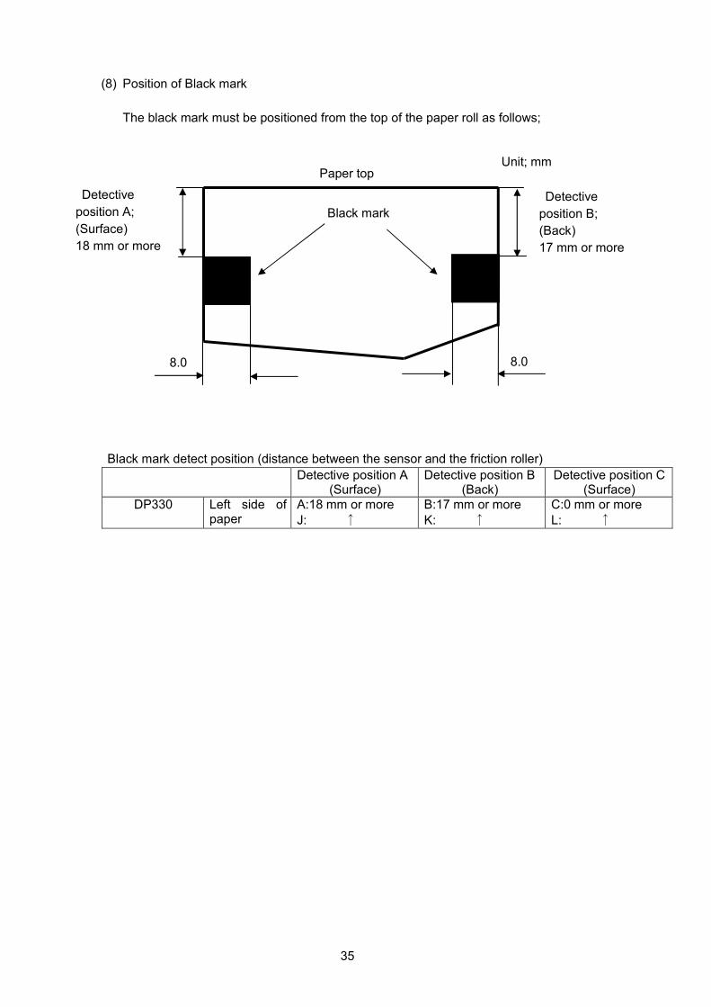
(8) Position of Black mark
The black mark must be positioned from the top of the paper roll as follows;
Black mark detect position (distance between the sensor and the friction roller)
Detective position A (Surface)
Detective position B (Back)
Detective position C (Surface)
DP330 Left side of paper
A:18 mm or more
J: ↑
B:17 mm or more
K: ↑
C:0 mm or more
L: ↑
8.0
Detective
position A;
(Surface)
18 mm or more
Black mark
Unit; mm
8.0
Paper top
Detective
position B;
(Back)
17 mm or more
36
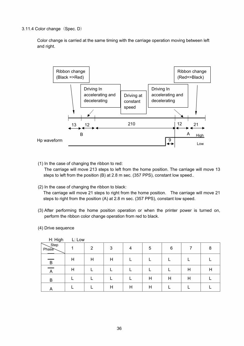
3.11.4 Color change(Spec. D)
Color change is carried at the same timing with the carriage operation moving between left
and right.
(1) In the case of changing the ribbon to red:
The carriage will move 213 steps to left from the home position. The carriage will move 13
steps to left from the position (B) at 2.8 m sec. (357 PPS), constant low speed..
(2) In the case of changing the ribbon to black:
The carriage will move 21 steps to right from the home position. The carriage will move 21
steps to right from the position (A) at 2.8 m sec. (357 PPS), constant low speed.
(3) After performing the home position operation or when the printer power is turned on,
perform the ribbon color change operation from red to black.
(4) Drive sequence
H: High L: Low Step Phase 1 2 3 4 5 6 7 8
B H H H L L L L L
A H L L L L L H H
B L L L L H H H L
A L L H H H L L L
Driving In
accelerating and
decelerating
Driving at
constant
speed
Driving In
accelerating and
decelerating
Ribbon change
(Black =>Red)
Ribbon change
(Red=>Black)
High
Low9 Hp waveform
A B
13 12 210 12 21
37
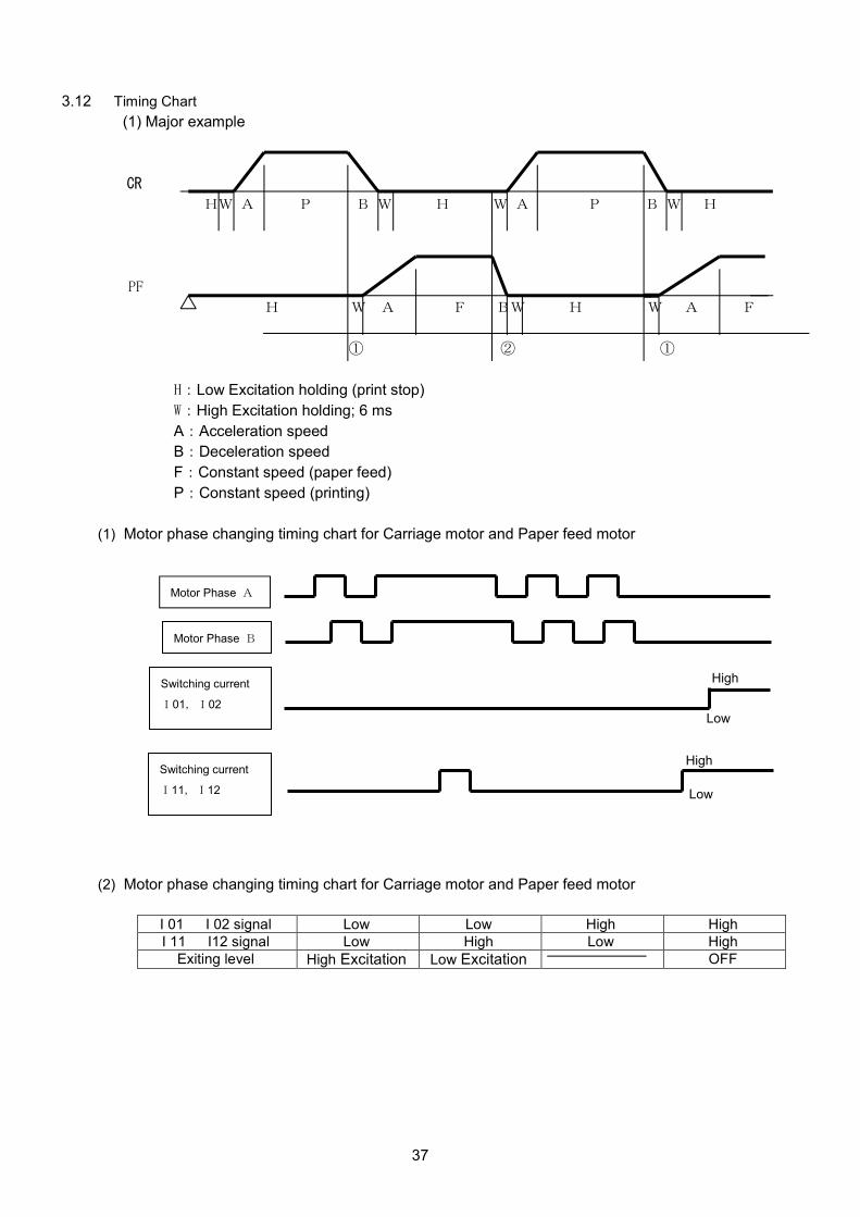
3.12 Timing Chart
(1) Major example
CR
HW A P B W H W A P B W H
PF
H W A F BW H W A F
① ② ①
H:Low Excitation holding (print stop)
W:High Excitation holding; 6 ms
A:Acceleration speed
B:Deceleration speed
F:Constant speed (paper feed)
P:Constant speed (printing)
(1) Motor phase changing timing chart for Carriage motor and Paper feed motor
(2) Motor phase changing timing chart for Carriage motor and Paper feed motor
I 01 I 02 signal Low Low High High
I 11 I12 signal Low High Low High
Exiting level High Excitation Low Excitation OFF
Motor Phase A
Motor Phase B
Switching current
I01,I02
Low
High Switching current
I11,I12
High
Low

38
4. SPECIAL REMARKS
4.1 Detection of Abnormalities
Step-out condition of the carriage motor is undetectable when it happens immediately.
Abnormality detection should be carried out to check on HP signal periodically.
(Refer to 3.5 (10))
4.2 Handling Ribbon Cartridge
1) Use the product designated by CITIZEN to maintain print quality and to obtain enough
durability.
2) Supplementation of ink for the ribbon is prohibited.
3) The ribbon cartridge must not be supplied, being mounted on the printer at the time of
shipment.
4.3 Re-winder
Paper rolling force should be less than 1.47 N (150 gr).
4.4 Appearance of stamping part
Rust may be observed on the edge of stamping plate due to using ordinal steel plate.
4.5 Printer installation precautions
1) As a precaution against noise and unstability, damping material, such as rubber, should be
provided in the installation location of the printer.
2) For installation, use the two U-grooves in the front of the printer and the protrusions in the
rear. The differential height of the four mounting portions must be 0.5 mm (0.02 inch) or less
Except for the mounting parts, the spacing must be made for the printer bottom.
3) The gap between the central positions of the printer and paper receiving section (provided
by the VAR) shall be ± 0.3 mm in the direction of paper width.
4) The exposed wiring of the PCB on the underside of the printer should not come into contact
With the mounting base or with any conductive parts that could short-circuiting.
Proper insulation should be provided.
4.6 Printer usage precautions
1) Since the printer uses permanent magnets in the motor and electromagnets solenoids,
it should be not be used in locations where metallic particles or high levels of dust and other
contamination exist.
2) Using the ground hole on the frame, take measures against static charge.
3) When paper is set to the printer, ensure that top edge has no shrinkage, no tear, and must
be cut at 90 degree against the side edge of paper. The top edge of copy paper must be
no gap in any direction between two papers.
4) To remove paper, pull the paper in forward or reverse by hand, or operate paper feeding
mechanism in forward.

39
5 Outer dimensions
STANDARD
MANUAL CUTTER

40
BLACK MARK SENSOR C POSITION

41
6. Packing
LABEL, CARTON
Drop test and Vibration test
(1) Drop test condition
①Order of drop
1 angle →3 corner →6 faces total 10 times
②Height
60cm
(2) Vibration test condition
Acceleration: 1G (constant)
Frequency: 5 - 60Hz
Sweep: 6 minutes (1 cycle) 10 times (total 1 hour)
Direction: X, Y, and Z
NH*****-**
LABEL, CARTON
PACKING TAPE
RoHS SIGN
CY2003901 LOT No
PRINTER BAR CODE
Printing
Position
DP330-DFVA CODE No. CJ CODE No.NH*********
QUANTIT’Y
20 PCS
42
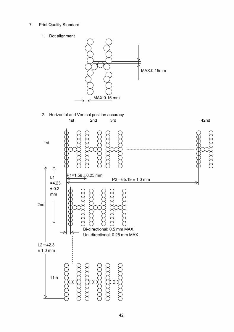
7. Print Quality Standard
1. Dot alignment
2. Horizontal and Vertical position accuracy
1st
2nd 3rd
42nd
1st
2nd
11th
Bi-directional: 0.5 mm MAX.
Uni-directional: 0.25 mm MAX
P1=1.59±0.25 mm P2=65.19 ± 1.0 mm
L1
=4.23
± 0.2
mm
L2=42.3
± 1.0 mm
MAX.0.15 mm
MAX.0.15mm

43
3. Slant of characters
4. Horizontal print position
± 3°
4.8 ± 3 mm
Forward