Embed Size (px)
Citation preview
Zeppelinstrasse 19 D-82205 Gilching Fon +49-8105-778090 [email protected] http://www.lcd-module.de
SPECIFICATION
CUSTOMER :
MODULE NO.: EA TFT035-32ANN
APPROVED BY:
( FOR CUSTOMER USE ONLY )
PCB VERSION: DATA:
SALES BY APPROVED BY CHECKED BY PREPARED BY
ISSUED DATE: 2018/06/18

Zeppelinstrasse 19 D-82205 Gilching Fon +49-8105-778090 [email protected] http://www.lcd-module.de
EA TFT035-32ANN Page 2 of 18
Contents 1.Summary
2.General Specification
3.Absolute Maximum Ratings
4.Electrical Characteristics
5.DC Characteristics
6.AC Characteristics
7.Optical Characteristics
8.Interface
9.Block Diagram
10.Reliability
11.Contour Drawing

Zeppelinstrasse 19 D-82205 Gilching Fon +49-8105-778090 [email protected] http://www.lcd-module.de
EA TFT035-32ANN Page 3 of 18
1.Summary This technical specification applies to 3.5” color TFT-LCD panel. The 3.5” color TFT-LCD panel is designed for camcorder, digital camera application and other electronic products which require high quality flat panel displays. This module follows RoHS. 1.1. Accessories ZIF connector for display, bottom contact EA WF050-40S ZIF connector for display, top contact EA WF050-40ST ZIF connector for touch panel, top contact EA WF050-10T

Zeppelinstrasse 19 D-82205 Gilching Fon +49-8105-778090 [email protected] http://www.lcd-module.de
EA TFT035-32ANN Page 4 of 18
2.General Specifications
Item Dimension Unit
Size 3.5 inch
Dot Matrix 320 x RGBx240(TFT) dots
Module dimension 76.9x 63.9x 3.26 mm
Active area 70.08 x 52.56 mm
Dot pitch 0.073 x 0.219 mm
LCD type TFT, Normally White, Transmissive
View Direction 12o’clock
Gray Scale Inversion Direction 6 o’clock
Backlight Type LED ,Normally White
With /Without TP Without TP
Surface Anti-Glare
*Color tone slight changed by temperature and driving voltage.

Zeppelinstrasse 19 D-82205 Gilching Fon +49-8105-778090 [email protected] http://www.lcd-module.de
EA TFT035-32ANN Page 5 of 18
3.Absolute Maximum Ratings
Item Symbol Min Typ Max Unit
Operating Temperature TOP -20 - +70 ℃
Storage Temperature TST -30 - +80 ℃
Note: Device is subject to be damaged permanently if stresses beyond those absolute maximum ratings listed above 1. Temp. ≦60℃, 90% RH MAX. Temp.>60℃, Absolute humidity shall be less than 90% RH at 60℃
00 20 40 60 80 100
10
20
30
40
Ambient Temperature(oC)
All
oeab
le F
orw
ard
Cur
rent
IF(
mA
) Ambient Tem. vs Alloeable Forward Curren
Zeppelinstrasse 19 D-82205 Gilching Fon +49-8105-778090 [email protected] http://www.lcd-module.de
EA TFT035-32ANN Page 6 of 18
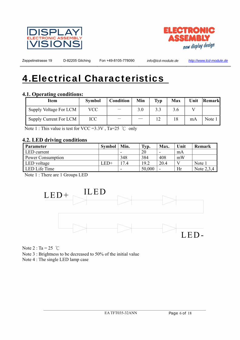
4.Electrical Characteristics 4.1. Operating conditions:
Item Symbol Condition Min Typ Max Unit Remark
Supply Voltage For LCM VCC - 3.0 3.3 3.6 V
Supply Current For LCM ICC - — 12 18 mA Note 1
Note 1 : This value is test for VCC =3.3V , Ta=25 ℃ only
4.2. LED driving conditions Parameter Symbol Min. Typ. Max. Unit Remark LED current - 20 - mA Power Consumption 348 384 408 mW LED voltage LED+ 17.4 19.2 20.4 V Note 1 LED Life Time - 50,000 - Hr Note 2,3,4 Note 1 : There are 1 Groups LED
LED + ILED
LED -
Note 2 : Ta = 25 ℃ Note 3 : Brightness to be decreased to 50% of the initial value Note 4 : The single LED lamp case

Zeppelinstrasse 19 D-82205 Gilching Fon +49-8105-778090 [email protected] http://www.lcd-module.de
EA TFT035-32ANN Page 7 of 18
5.DC CHARATERISTICS
Parameter Symbol Rating
Unit Condition Min Typ Max
Low level input voltage VIL 0 - 0.3VCC V
High level input voltage VIH 0.7VCC - VCC V
Zeppelinstrasse 19 D-82205 Gilching Fon +49-8105-778090 [email protected] http://www.lcd-module.de
EA TFT035-32ANN Page 8 of 18
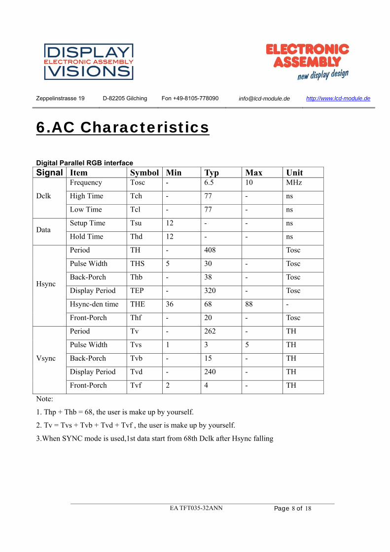
6.AC Characteristics Digital Parallel RGB interface
Signal Item Symbol Min Typ Max Unit
Dclk
Frequency Tosc - 6.5 10 MHz
High Time Tch - 77 - ns
Low Time Tcl - 77 - ns
Data Setup Time Tsu 12 - - ns
Hold Time Thd 12 - - ns
Hsync
Period TH - 408 Tosc
Pulse Width THS 5 30 - Tosc
Back-Porch Thb - 38 - Tosc
Display Period TEP - 320 - Tosc
Hsync-den time THE 36 68 88 -
Front-Porch Thf - 20 - Tosc
Vsync
Period Tv - 262 - TH
Pulse Width Tvs 1 3 5 TH
Back-Porch Tvb - 15 - TH
Display Period Tvd - 240 - TH
Front-Porch Tvf 2 4 - TH
Note:
1. Thp + Thb = 68, the user is make up by yourself.
2. Tv = Tvs + Tvb + Tvd + Tvf , the user is make up by yourself.
3.When SYNC mode is used,1st data start from 68th Dclk after Hsync falling

Zeppelinstrasse 19 D-82205 Gilching Fon +49-8105-778090 [email protected] http://www.lcd-module.de
EA TFT035-32ANN Page 9 of 18
6.1. Waveform
Figure 7.1.1 Data Transaction Timing in Parallel RGB (24 bit) Interface (SYNC Mode)

Zeppelinstrasse 19 D-82205 Gilching Fon +49-8105-778090 [email protected] http://www.lcd-module.de
EA TFT035-32ANN Page 10 of 18
Figure 6.1.2 Data Transaction Timing in Parallel RGB (24 bit) Interface (DE Mode)
6.2. Clock and Sync waveforms
Figure 6.2.1 IHS and IVS timing waveforms

Zeppelinstrasse 19 D-82205 Gilching Fon +49-8105-778090 [email protected] http://www.lcd-module.de
EA TFT035-32ANN Page 11 of 18
Figure 6.2.2 TV and TH timing waveforms
6.3. Reset Timing Chart The RESET input must be held at least 1ms after power is stable

Zeppelinstrasse 19 D-82205 Gilching Fon +49-8105-778090 [email protected] http://www.lcd-module.de
EA TFT035-32ANN Page 12 of 18
7.Optical Characteristics
Ta=25±2℃, IL=20mA Note 1: Definition of viewing angle range
Fig. 8.1. Definition of viewing angle
Note 2: Test equipment setup: After stabilizing and leaving the panel alone at a driven temperature for 10 minutes, the measurement should be executed. Measurement should be executed in a stable, windless, and dark room. Optical specifications are measured by Topcon BM-7orBM-5 luminance meter 1.0° field of view at a distance of 50cm and normal direction.
Item Symbol Condition. Min Typ. Max. Unit Remark
Response time Tr
θ=0˚、Φ=0˚- 10 - ms
Note 3,5 Tf - 15 - ms
Contrast ratio CR At optimized
viewing angle
300 350 - - Note 4,5
Color Chromaticity White Wx
θ=0˚、Φ=0 0.26 0.31 0.36 - Note 2,6,7
Wy 0.28 0.33 0.38 - -
Viewing angle (Gray Scale Inversion
Direction)
Hor. ΘR
CR≧10
- 55 -
Deg. Note 1 ΘL - 55 -
Ver. ΦT - 45 - ΦB - 50 -
Brightness - - 350 420 - cd/m2 Center of display

Zeppelinstrasse 19 D-82205 Gilching Fon +49-8105-778090 [email protected] http://www.lcd-module.de
EA TFT035-32ANN Page 13 of 18
Fig. 8.2. Optical measurement system setup
Note 3: Definition of Response time: The response time is defined as the LCD optical switching time interval between “White” state and “Black” state. Rise time, Tr, is the time between photo detector output intensity changed from 90%to 10%. And fall time, Tf, is the time between photo detector output intensity changed from 10%to 90%
B la c k ( T F T O N ) W h i te ( T F T O F F )W h i te ( T F T O F F )1 0 0 %9 0 %
1 0 %0 %
D is p l a yD a t a
Note 4: Definition of contrast ratio: The contrast ratio is defined as the following expression.
Lum inance m easured w hen LC D on the "W hite" stateC ontrast ratio (C R ) =
Lum inance m easured w hen LC D on the "B lack" state Note 5: White Vi = Vi50 ± 1.5V Black Vi = Vi50 ± 2.0V “±” means that the analog input signal swings in phase with VCOM signal. “±” means that the analog input signal swings out of phase with VCOM signal. The 100% transmission is defined as the transmission of LCD panel when all the input terminals of module are electrically opened. Note 6: Definition of color chromaticity (CIE 1931) Color coordinates measured at the center point of LCD Note 7: Measured at the center area of the panel when all the input terminals of LCD panel are electrically opened.
Zeppelinstrasse 19 D-82205 Gilching Fon +49-8105-778090 [email protected] http://www.lcd-module.de
EA TFT035-32ANN Page 14 of 18
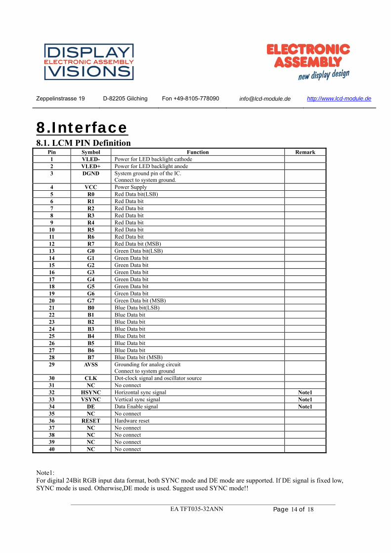
8.Interface 8.1. LCM PIN Definition
Pin Symbol Function Remark 1 VLED- Power for LED backlight cathode 2 VLED+ Power for LED backlight anode 3 DGND System ground pin of the IC.
Connect to system ground.
4 VCC Power Supply 5 R0 Red Data bit(LSB) 6 R1 Red Data bit 7 R2 Red Data bit 8 R3 Red Data bit 9 R4 Red Data bit
10 R5 Red Data bit 11 R6 Red Data bit 12 R7 Red Data bit (MSB) 13 G0 Green Data bit(LSB) 14 G1 Green Data bit 15 G2 Green Data bit 16 G3 Green Data bit 17 G4 Green Data bit 18 G5 Green Data bit 19 G6 Green Data bit 20 G7 Green Data bit (MSB) 21 B0 Blue Data bit(LSB) 22 B1 Blue Data bit 23 B2 Blue Data bit 24 B3 Blue Data bit 25 B4 Blue Data bit 26 B5 Blue Data bit 27 B6 Blue Data bit 28 B7 Blue Data bit (MSB) 29 AVSS Grounding for analog circuit
Connect to system ground
30 CLK Dot-clock signal and oscillator source 31 NC No connect 32 HSYNC Horizontal sync signal Note1 33 VSYNC Vertical sync signal Note1 34 DE Data Enable signal Note1 35 NC No connect 36 RESET Hardware reset 37 NC No connect 38 NC No connect 39 NC No connect 40 NC No connect
Note1: For digital 24Bit RGB input data format, both SYNC mode and DE mode are supported. If DE signal is fixed low, SYNC mode is used. Otherwise,DE mode is used. Suggest used SYNC mode!!

Zeppelinstrasse 19 D-82205 Gilching Fon +49-8105-778090 [email protected] http://www.lcd-module.de
EA TFT035-32ANN Page 15 of 18
Mode D[23:16] D[15:8] D[7:0] IHS IVS DEN
24 bit RGB R[7:0] G[7:0] B[7:0] HSYNC VSYNC
DE signal is fixed low for SYNC mode
Floating if not used
Floating if not used
DE for DE Mode
8.2. Basic Display Color and Gray Scale

Zeppelinstrasse 19 D-82205 Gilching Fon +49-8105-778090 [email protected] http://www.lcd-module.de
EA TFT035-32ANN Page 16 of 18
9.Block Diagram
VS
HS
DE
FPC
DCLK
RESET
Power supply
Backlight LED
Paralle- 24 bit RGB
Source +GateDriver
GrayscaleManipulation
Voltage
TCON
VCON
Charge pump
B/L
R0~R7,G0~G7,B0~B7HSYNC, VSYNCDCLK,DE
RESET
VCC
LED_Anode , LED_Cathode
3.5"320(RGB)x240
LCD Driver Chip (COG)

Zeppelinstrasse 19 D-82205 Gilching Fon +49-8105-778090 [email protected] http://www.lcd-module.de
EA TFT035-32ANN Page 17 of 18
10.Reliability Content of Reliability Test (Wide temperature, -20℃~70℃)
Note1: No dew condensation to be observed. Note2: The function test shall be conducted after 4 hours storage at the normal Temperature and humidity after remove from the test chamber. Note3: The packing have to including into the vibration testing.
Environmental Test
Test Item Content of Test Test Condition Note High Temperature storage
Endurance test applying the high storage temperature for a long time.
80℃ 200hrs
2
Low Temperature storage
Endurance test applying the low storage temperature for a long time.
-30℃ 200hrs
1,2
High Temperature Operation
Endurance test applying the electric stress (Voltage & Current) and the thermal stress to the element for a long time.
70℃ 200hrs
——
Low Temperature Operation
Endurance test applying the electric stress under low temperature for a long time.
-20℃ 200hrs
1
High Temperature/ Humidity Operation
The module should be allowed to stand at 60℃,90%RH max
60℃,90%RH 96hrs
1,2
Thermal shock resistance
The sample should be allowed stand the following 10 cycles of operation -20℃ 25℃ 70℃ 30min 5min 30min 1 cycle
-20℃/70℃ 10 cycles
——
Vibration test Endurance test applying the vibration during transportation and using.
Total fixed amplitude : 15mm Vibration Frequency : 10~55Hz One cycle 60 seconds to 3 directions of X,Y,Z for Each 15 minutes
3
Static electricity test Endurance test applying the electric stress to the terminal.
VS=±600V(contact), ±800v(air), RS=330Ω CS=150pF 10 times
——
Zeppelinstrasse 19 D-82205 Gilching Fon +49-8105-778090 [email protected] http://www.lcd-module.de
EA TFT035-32ANN Page 18 of 18
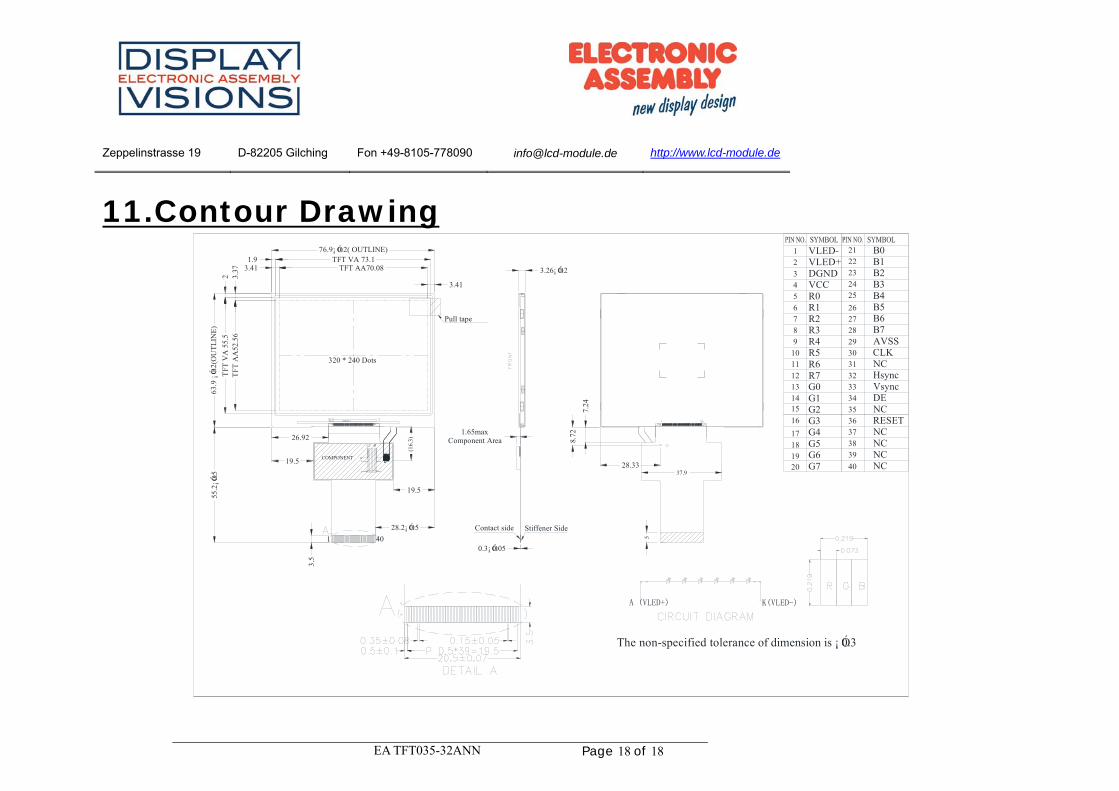
11.Contour Drawing
COMPONENT
76.9¡ Ó0.2( OUTLINE)
63.9
¡Ó0.
2(O
UT
LIN
E)
TFT AA70.08
TFT
AA
52.5
6
3.26¡ Ó0.2
3.37 3.41
0.3¡ Ó0.05
7.24
28.2¡ Ó0.5
55.2
¡Ó0.5
3.5
26.92
19.5
8.72
Stiffener SideContact side
28.33
320 * 240 Dots
1.65maxComponent Area
XRYU XL
3.41
The non-specified tolerance of dimension is ¡ Ó0.3
1 40
37
3938
26
32
3635
3334
29
3130
2827
40
15
21
2524
2223
18
2019
17
16
2
3
5
6
4
9
8
1011
7
1
1314
12
VLED-VLED+DGNDVCCR0R1R2R3R4R5R6R7G0G1G2G3G4G5G6G7
B0B1B2B3B4B5B6B7AVSSCLKNCHsyncVsyncDENCRESETNCNCNCNC19.5
5
37.9
A (VLED+) K(VLED-)
YD
TFT VA 73.11.9
2T
FT V
A 5
5.5
(16.
3)
Pull tape