Embed Size (px)
Citation preview
1-120 585112-01
1993 Specifications CSJ 0924-06-167
SPECIAL SPECIFICATION5851
Water, Reclaim Water, and Sanitary Sewer Systems
1. Scope of Work. This work shall include the following:
The Water work consist of the installation of approximately 40 LF of 48-inch ApprovedPipe, 2400 LF of 36-inch Approved Pipe, 9100 LF of 24-inch Approved Pipe, 440 LF of 12-inch C900/CL200 PVC Pipe, 440 LF of 8-inch C900/CL200 PVC Pipe, 100 LF of 60-inchSteel Casing, 285 LF of 48-inch Steel Casing, butterfly, air/vacuum and gate valves,corrosion protection system and test stations, services, fittings and all necessaryappurtenances for the completed main structure, including associated Trench Safety System.
The Reclaim Water work consists of the installation of approximately 2470 LF of 20-inchC905/DR18 PVC Pipe, 8911 LF of 16-inch C905/DR18 PVC Pipe, 385 LF of 30-inch SteelCasing, butterfly, air/vacuum and gate valves, corrosion protection system and test stations,services, fittings and all necessary appurtenances for the completed main structure, includingassociated Trench Safety System.
The Sanitary Sewer work consists of the installation of approximately 2905 LF of 15-inchSDR35 PVC, 6669 LF of 12-inch SDR35 PVC, 2007 LF of 8-inch SDR35 PVC, manholes,and all necessary appurtenances for the completed main structure, including associated TrenchSafety System.
2. Water, Reclaim Water and Sanitary Sewer Contractor’s Minimum QualificationsCriteria. The Bidder, or at least three Key Personnel employed by the Bidder, mustdemonstrate Successful completion of one project similar in nature and scope of this project,within the past five (5) years and one project with a value of at least 50% of the value bid forthe Water, Reclaim Water and Sanitary Sewer portion of this project.
Project requires the installation of Water, Reclaim Water and Sanitary Sewer Systemsincluding pressure pipe of 48-inch, 36-inch, 24-inch, 20-inch, 16-inch, 12-inch and 8-inch,corrosion protection system and test stations, 15-inch, 12-inch and 8-inch PVC sewer pipe,and miscellaneous appurtenances and fittings. Project also includes a portion of sewer maininstallation with a depth of 15-feet and greater, utilizing an approved deep excavationTrench Safety System.
Bidder to demonstrate successful projects with similar requirements. This requirement maybe satisfied by employing the services of a qualified subcontractor. Provide name ofsubcontractor and list of similar pipe size project.
3. Contractor’s Responsibility for Installation of the Water, Reclaim Water, and SanitarySewer System. It is the intent of these specifications that the installation of the Water,Reclaim Water, and Sewer Mains be a complete workable system, functioning in accordance

2-120 585112-01
with the specified purpose. Therefore, it is the direct responsibility of the Contractor tofurnish, install and construct a complete system as required by the plans for the bid unitprices in the Contract, and to take account of all subsidiary requirements for the materialsand other items furnished to the end that the Water, Reclaim Water, and Sewer Mainsfunction in accordance with the specified requirements.
4. Schedule of Work. Contractor shall fully coordinate his work with that of otherContractors and any operations required from the El Paso Water Utilities in advance in orderto avoid delays and conflicts. Personnel from the El Paso Water Utilities will assist inworking out the coordination between the construction operations and the operation of theexisting facilities, but it is the Contractor’s responsibility to clear all his operations thatmight interfere with such existing operations with the Project Engineer.
5. Temporary Service. Contractor shall take into consideration that service outages tobusinesses and residences are limited to a maximum of four (4) consecutive hours within a24-hour period. Contractor shall make provisions to immediately provide and maintaintemporary service to all customers (businesses, residences, etc.) should the service outageextends beyond the four-hour outage limit. However, temporary service shall beimmediately provided to any customer that requests it prior to the four-hour outage limit.
6. Inspection of Materials. All materials furnished by the Contractor shall be subject to theinspection and approval of the Engineer, the El Paso Water Utilities, or their representative,at any and all times during the progress of the work and until the final completion of thesame. As soon as the materials are tested and inspected, the Contractor shall immediatelyremove all rejected material from the work, and to a point such distance there from as theEngineer may require. No material shall be used before being inspected and approved bythe Engineer, or his representative, but failure or neglect on the part of the Engineer, or hisrepresentative to condemn or reject inferior materials or work shall not be construed toimply any acceptance of the same should its inferiority become evident at any time prior tofinal acceptance of the work.
7. Removed Materials. Equipment, piping, appurtenances and other components scheduled tobe salvaged shall be returned and delivered by the Contractor to the El Paso Water UtilitiesMesa Plant, 4200 Fred Wilson Road. However, if the Contractor removes any section ofpipe that is scheduled to be abandoned, then it will become the responsibility of theContractor to properly dispose of it.
8. Water for Construction. Water for all construction purposes will be provided at theContractor’s expense for trenching, water, reclaim water, and sanitary sewer installation,filling, testing, disinfecting and flushing existing and proposed installations, and all stormdrain, landscape, roadway construction, dust control, compaction and clean-up. At no timewill un-metered water consumption be allowed, nor will the Contractor be allowed tooperate a fire hydrant. Construction water can be provided upon approval and meterdeposits and fees to the Utility have been paid on an existing fire hydrant. The fire hydrantmeter fee is $1,600.00, which includes a meter and backflow preventor fee of $1,500.00 anda set-up and removal fee of $100.00 for the installation and removal of the meter. The firehydrant meter will not be removed from the assigned fire hydrant by anyone other thanUtility Personnel. An outlet valve will be provided with the fire hydrant meter forContractor use. A water loss fee of $500.00 will be assessed to the Contractor for each

3-120 585112-01
occurrence that violates the above. Charges due will be deducted from the depositedamount. Charges in excess of the deposit amount must be paid before the project will beaccepted into the Utility System. Any excess deposit will be refunded promptly.
Construction water drawn through fire hydrant meters will be charged to the Contractor at ausage rate of $1.59 per hundred cubic feet. Fire hydrants meters will be installed andremoved by EPWU’s personnel only. Fire hydrant meters have a locking device and a built-in backflow preventor. The Contractor is no longer responsible for providing his ownbackflow preventor for fire hydrant meters. Water used to fill, pressure test, and disinfectwater main lines will be billed at the standard construction water rate of $1.59 per hundredcubic feet and will be calculated at one and a half times the volume of the installed pipe.
The Contractor may, with the approval of the Engineer, make other arrangements and securewater for construction purposes from a source of his own choosing, including but not limitedto Reclaimed Water from the Wastewater Treatment Plants, which is available at areasonable cost. The Contractor shall obtain information, terms and conditions of service,application process, and other requirements from the El Paso Water Utilities, EngineeringDeveloper Services Section. Issuance of a construction meter or standpipe requires adeposit. Standard forms are available at the El Paso Water Utilities’ EngineeringDepartment. The Contractor shall provide such facilities as may be required for transportingand utilizing this water, at his own cost.
Upon completion of the project, the Contractor must call the Engineering DeveloperServices Section at 594-5540 or 594-5682 to have the meter removed. Upon meter removal,the Contractor will be assessed for the water consumed plus any damages to the fire hydrantand/or fire hydrant meter assembly.
9. Care of Existing Structures. Existing buildings, structures, power and telephone lines,trees, fences, water pipes, gas lines, sewer or other conduits, embankments, monuments andsundry structures in the vicinity of the work shall be supported and protected from injury bythe Contractor during construction and until completion of the work. The Contractor shallbe liable for all damages done to such structures, as herein provided, and shall save and keepthe Owner harmless from any liability or expense for injuries, damages, or repairs to it.

4-120 585112-03
I. Water Mains and Reclaim Water Mains
I. Water Mains and Reclaim Water Mains
1. Description. This Item shall govern for all materials and work necessary for the installationof all water mains, reclaimed water mains, and all distribution lines connected to the variousstructures as shown on the plans.
The data furnished on the plans regarding the size and location of utility lines has beenobtained from record information, field surveys and the various utility companies.However, the Engineer does not assume responsibility for the accuracy of the informationpresented, nor does it warrant that all of the utility lines have been shown.
2. Materials. Each piping system shall be installed using the materials designated on the plansand in details for each particular system. The material so designated shall be furnished inaccordance with the following applicable specification.
Unless otherwise specified on the plans, all water pipe and reclaim water pipe shall be asspecified in the attached Specifications.
All valves shall be as specified in the attached Specifications "Gate Valves” and “ButterflyValves" unless otherwise noted or directed by the Engineer.
Valves 12-inch and smaller shall be bronze gate valves and shall bear the manufacturer'sname, conspicuous brand, or trademark. Gate valves shall be rated for a minimum of 200psi, stream working pressure, and must bear a clear indication of working pressure for whichit is designed. Gate valves shall comply with AWWA C500-86, "Gate Valves for Water andSewage Systems". Gate valves shall be provided with integral seats and threaded endconnections.
Valves shall be tape-wrapped as described in this specification for ductile iron fittings. TheContractor shall submit proof of compliance with AWWA C500 for gate valves,AWWA C504 for butterfly valves as well as the additional conditions listed above.
All valves shall be installed in valve boxes as shown on the plans. Valve boxes shall be castiron and shall have suitable base castings to fit properly over the bonnets of their respectivevalves and heavy top sections with stay-put covers. Covers shall be hot-dip galvanized.Adjustable shaft valve boxes shall be concrete or cast iron Brooks No. 3RT, Christie G5,Empire 7 1/2 valve extension box, or equal. Box covers shall be impressed with lettering asshown on the plans (City Water, Reclaim Water). Wrench nuts shall be provided on buriedvalves and where specified. Extended wrench nuts shall be provided if necessary so that thenut will be within (6-inches) of the valve box cover. Wrench nuts shall comply withSection 3.16 of AWWA C500, "Gate Valves (3-inch) through (48-inch) NPS for Water andSewage System". A minimum of two (2) operating keys, but no less than one (1) key perevery 10 valves, shall be provided for operation of the wrench nut operated valves.
All pipe 3-inch and smaller shall be Type K annealed or drawn copper conforming toASTM B88-83, "Seamless Copper Water Tube". Fittings for copper piping shall be wroughtcopper or bronze solder joint pressure fittings conforming to ANSI B16.22-80, "WroughtCopper and Copper Alloy Solder Joint Pressure Fittings". Solder used in joining copper

5-120 585112-03
I. Water Mains and Reclaim Water Mains
pipe and fittings shall be alloy Grade 50B in accordance with ASTM B32-83, "SolderMetal".
All pipe 4-inch and larger shall be PVC, unless otherwise indicated on the plans or directedby the Engineer, and shall conform to attached Specifications. Fittings for PVC pipe shallbe ductile iron with minimum thickness of wall as defined in ANSI 21.50-81, "ThicknessDesign of Ductile Iron Pipe" for a pressure rating of 200 psi. Fittings shall be furnished withall necessary glands, gaskets, bolts, etc., as may be required to complete the joints. Rubber-gasket joints for mechanical joints or "push-on" type joints shall conform to therequirements of ANSI Standard A21.11 (AWWA Standard C-111), "Rubber-Gasket Jointsfor Ductile-Iron Pressure Pipe and Fittings", latest revision.
All ductile iron pipe and fittings shall conform to the attached Specification "Ductile IronPipe and Fittings". All ductile iron pipe and fittings shall be tape wrapped prior to backfill.Tape wrap shall consist of petroleum-based mastic and wrapping tapes carefully applied inaccordance with the manufacturer's recommendations. Loose scale, rust, dirt, moisture, andsharp projections shall be removed and all surface hand rubbed with priming pasterecommended by the manufacturer. Tape shall then be spirally wrapped with a 55 percentoverlap and sufficient tension and pressure to provide continuous adhesion withoutstretching the tape. Edges of the tape shall be continuously smoothed and sealed by handduring wrapping. Smooth contours shall have a minimum thickness of 50 mils while nuts,bolts and sharp projections shall be 100 mils. Tape wrap coating system shall be DENSCOSystem T-1, Trenton No. 1 Wax Tape, or approved equal.
Thrust restraint shall be provided for all water and reclaim water pipe. Joint restraint shallbe accomplished by serrated "Gripping Surfaces" around the pipe circumference with afollower gland bolting to a mechanical joint fitting or belled-end mating piece of similarserrated design. Restraint fittings shall be manufactured by EBBA Iron Sales, Inc.Models 2000/1500, JCM Industries, Inc., Models 610/620, or equal approved by theEngineer. Joint restrains shall be rated for 200 psi working pressures with a 2:1 safety factorfor pressure surges. Restraints shall be furnished with heavy finish coat of corrosioninhibiting metal primer and all bolts, nuts, and washers shall be of high-strength, low alloysteel as specified in ANSI/AWWA C211/A21.11. Joint restraints shall also be encasedaccording to AWWA C105-88, "Polyethylene Encasement for Ductile Iron Piping". Thrustrestraint shall be provided at all appurtenances as shown on the plans. The Contractor shalldetermine the length of pipe to be restrained accordingly with the thrust restraint.
Fire hydrants shall be as specified in attached Specification, “Fire Hydrants”.
Service taps shall be provided to all proposed reclaim water meters and service connectionsin accordance with AWWA C800-89, "Underground Service Line Valves and Fittings".Each service tap shall include all necessary pipe, fittings, valves, and labor. Saddles andcorporation stops shall be provided for all service taps 2-inches or smaller. Saddles shallconsist of a brass saddle with double or extra wide stainless steel straps, which clamp aroundthe entire pipe. All bolts, nuts, and washers shall be stainless steel and a watertight sealprovided by a neoprene or Buna N gasket. Saddles shall be rated for 200 psi and shallcomply with AWWA Manual M23, "PVC Pipe-Design and Installation". Saddles shall beFord Meter Box Company, Inc., Style 202BS, or approved equal with AWWA threads.Corporation stops shall be brass with AWWA inlet threads and copper tube outlet

6-120 585112-03
I. Water Mains and Reclaim Water Mains
connections. Corporation stops shall be solid brass and conform to AWWA C800-89 withAWWA inlet threads and copper tube outlet connections. Corporation stops shall be FordMeter Box Company, Inc. Model FB1000, or approved equal. Service taps larger than 2inches shall be made by providing a tee in the main line with threaded outlet or flangedcoupling and a gate valve of the same size as the existing water service.
3. Construction Methods. Care shall be exercised in handling, loading, unloading, andstoring pipe and fittings. All material, to which this specification applies, shall be storedunder cover until used. All pipe shall be transported in a vehicle with a bed long enough toallow pipe lengths to lie flat. Pipe shall not be subjected to undue bending or concentratedload at any point. Any section of pipe that has been dented or damaged shall be discardeduntil the damaged section of pipe is cut out. The undamaged sections of pipe shall berejoined with a coupling. Pipe fittings shall be protected from the weather duringconstruction prior to the time that they are welded or joined to the pipe.
All pipe shall be placed in a trench with a minimum of 36-inches of cover, except asotherwise specifically noted on the plans. All pipes shall have a firm, uniform bearing forthe entire length of each pipeline. The Contractor shall take precautionary measures toprevent uneven settlement of each pipeline.
Wedging or blocking of pipe will not be permitted. All rock, lumber, and rubbish shall beremoved from the trenches. If trench or surrounding soil is extremely rocky, the pipe shallbe bedded in sand or other approved material.
Pipe shall not be laid when there is water in the trench, or when the atmospheric temperatureis 32°F or below.
All foreign matter shall be removed from the inside of the pipe before welding or coupling.Pipe shall be kept clean during installation.
All pipelines crossing under culverts and storm drains shall be encased in the type and sizeof encasement pipe indicated on the plans. Casings shall extend a minimum of 5-feetbeyond each curb or edge of shoulder.
All excavation, backfill and dewatering for water pipelines shall conform to the "Excavationand Backfill for Structures & Pipelines" of these attached specifications.
When indicated on the plans, trenches shall be backfilled to the elevations shown, withstabilized backfill containing aggregate, water and a minimum of 2-sacks of PortlandCement per cubic yard of material as placed. Cement and water shall conform to therequirements of the Standard Specification Item 360, "Concrete Pavement", of the standardspecifications. Aggregate shall be as noted on the plans and/or as approved by the Engineer.
Concrete thrust restraint shall be provided at all valves, tees, bends, plugs and caps as shownon the plans. All existing pipe and valves are assumed to be adequately restrained. TheContractor shall verify type and size of existing thrust restraint and obtain confirmation ofadequacy of such restraint with the Engineer. The Contractor shall also submit for approval,by the Engineer, a detailed sequence of construction and construction methods forconnection of all PVC water and reclaim water piping to existing water system.

7-120 585112-03
I. Water Mains and Reclaim Water Mains
All pipe and fittings to be jointed with solder shall be free from all burrs and wire brushed orsteel wool cleaned. After cleaning, a paste flux shall be evenly and sparingly applied to thesurfaces to be joined. Solder shall then be applied and flame passed toward the center of thefitting until the solder disappears. All excess solder shall be removed while it is still plastic.Absolutely no acid flux or acid wipe shall be used in making solder joints. Wherever coppertubing or fittings come in contact with steel or ductile iron, the Contractor shall providedielectric protection.
Fire hydrants shall be installed as shown on the plans and in accordance with NFPA 24-87,"Private Fire Service Mains and their Appurtenances" and with the approval of the FireMarshal.
The Contractor will connect the new Type K copper piping to new services after theContractor has successfully pressure tested all piping. The Contractor shall coordinate allconstruction activities with the Engineer so as to prevent loss of water service to anyresidence or establishment served by the existing water system. Where temporarydisconnection of water services is unavoidable, the Contractor shall notify the Engineer andall affected water users in writing at least 5 working days prior to the loss of service. Lossof service shall not exceed 4 hours in duration for any 24-hour period and must be approvedby the Engineer.
4. Testing. The Contractor shall conduct hydrostatic pressure tests on all water and reclaimwater piping. The test results will be used to evaluate the materials and constructionmethods on the pipeline sections, and successful tests shall be mandatory for the acceptanceof the lines. The Contractor shall furnish all materials and equipment for testing includingpressure pumps, valves, plugs, calibrated measuring equipment and calibrated pressuregages. Test plugs, valves, and piping shall be securely braced to prevent movement.Control valves and pumps shall be located at ground level during tests. Test pressures shallfall within the upper half of the pressure gages range. Test procedures shall be as follows:
(1) Isolate section of line to be tested by closing valves and installing temporary plugs andbracing.
(2) Slowly fill isolated section with clean water while relieving air from high points of theline.
(3) Apply water pressure through high-pressure pump until the internal pipeline pressurereaches 150 psi.
(4) Shut off pump and observe pressure.
(5) Repeat steps 3 and 4 until pressure is stable at 150 psi.
(6) Begin 60-minute test.
(7) After 60 minutes, add water through high-pressure pump until 150 psi is reached.
(8) If the volume of water required to reestablish the 150 psi internal pipeline pressure isless than or equal to 0.02 gallons per inch of nominal diameter per 100 feet of lengthtested then the pipeline shall be presumed free from defect. When the leakage rate

8-120 585112-03
I. Water Mains and Reclaim Water Mains
exceeds this rate, the Contractor shall make necessary inspections to determine thecause of excessive leakage and make needed repairs at his own expense.
(9) Repeat steps 1 and 8 until each pipeline section passes.
(10) Thoroughly flush all water pipelines with potable water.
5. Disinfection. After testing and backfill have been completed, the potable water system andreclaim water system, upon final completion, shall be disinfected according toAWWA C651-86, "Disinfecting Water Mains". The solution for disinfecting shall containnot less than 25 parts per million of available chlorine.
The chlorinating solution shall be sodium hypochlorite, labeled to indicate percent availablechlorine. This solution shall be introduced into the potable water lines at a minimum rate of1.44 gallons of solution per 100 linear feet of 12 inch main per percent of available chlorine,i.e.: 10 percent solution would require 0.144 gallons of solution per 100 feet. The methodof introducing the disinfectant solution and the time at which this operation is to begin shallbe as approved by the Engineer.
The disinfectant solution shall remain in the system for a period of 24 hours, during whichtime, all valves, faucets, and fountains on the potable water system and reclaim water systemshall be opened and closed several (not less than 6) times. After the 24-hour period, thewater in the pipeline shall be tested in the presence of the Engineer. If the chlorineconcentration is less than 10 parts per million, disinfecting will be repeated. The lines shallbe flushed with water from the permanent water source until there is no detectable odor ortaste of chlorine from any outlet. The water shall then be tested for bacteria by a qualifiedlaboratory. Disinfecting shall be repeated if bacteria are present. A testing report shall besubmitted to the Engineer.
The disinfecting procedure shall be repeated whenever repairs are made to the potable watersystem.
6. Measurement.
(1) “Approved Pipe”, of each type and size, specified will be measured by the linear foot,complete in place. Thrust blocks, fittings, and couplings shall be considered subsidiaryto the respective types and sizes of pipe and will not be paid for directly. Threadedoutlets, bends, and adapters of each type and size specified shall be consideredsubsidiary to Approved Pipe installation. The price shall also include all cost associatedwith the cutting, capping, and removal of existing water lines; coordination; excavation;backfilling and embedment; compaction and compaction testing for utilities; all pipeaccessories, including cathodic protection system; disinfection; testing; and dewateringand disposal of water where required.
(2) “Polyvinyl Chloride (PVC) Water Pipe and Reclaim Water Pipe”, of each type andsize specified, will be measured by the linear foot, complete in place. Thrust blocks,fittings, and couplings shall be considered subsidiary to the respective types and sizes ofpipe and will not be paid for directly. The price shall also include all cost associatedwith the cutting, capping, and removal of existing water lines and valves; coordination;excavation; backfilling and embedment; compaction and compaction testing for
9-120 585112-03
I. Water Mains and Reclaim Water Mains
utilities; all pipe accessories; disinfection; testing; and dewatering and disposal of waterwhere required.
(3) “Steel Casing” of the type and size specified will be measured by the linear foot,complete and in place.
(4) “Air Release Valve with Manhole and Assembly”, will be measured as eachcomplete unit of the particular size specified on the plans including but not limited to:isolation valve, manhole, manhole ring and cover, vent piping, guard posts,miscellaneous piping to the pipeline, and all other appurtenances and labor for acomplete working installations as described on the plans.
(5) Blow-off Connection with Manhole”, will be measured as each complete unit asspecified on the plans, including but not limited to isolation valve, manhole, manholering and cover, vent piping, guard posts, miscellaneous piping to the pipeline and allother appurtenances and labor for a complete working installation as described on theplans.
(6) “Gate Valve”, of the size specified measured by each unit, complete in place. Valveboxes and thrust blocks shall be considered subsidiary to the respective sizes of gatevalves.
(7) “Top Outlet with Fittings”, of the size specified measured by each unit, complete inplace. Valve boxes and thrust blocks shall be considered subsidiary to the respectivesizes of top outlet with fittings.
(8) “1 ½” Water Service with BFP (future)”, will be measured as each unit of theparticular size of water service, complete in place. Valves, fitting appurtenances andrequired reduced pressure backflow preventor shall be considered subsidiary and willnot be paid for directly.
(9) “Butterfly Valve with Manhole” will be measured for payment per each butterflyvalve adjusted to final grade, including but not limited to manhole, thrust blocks,operation assembly, and any other incidentals required for a working assembly.
(10) “Fire Hydrant Complete”, will be measured as each complete unit in place. Thisprice shall include all fittings along with gate valve and other appurtenances to ensure acomplete working fire hydrant.
(11) “Trench Excavation Protection”, work prescribed under this Item will be measuredby the linear foot for the installation of the Trench Safety System and shall include anydesign, testing, inspection, or additional excavation and backfill required, forfurnishing, placing, maintaining and removing all shoring, sheeting, or bracing; forrequired compaction; and for all labor, materials, tools, equipment, and any incidentalsnecessary to complete the "Trench Safety System" work.
7. Payment.
(1) “Approved Pipe Main”, measured as provided under “Measurement”, will be paid forat the unit price bid for “Approved Pipe”, for the particular type and size of water main

10-120 585112-03
I. Water Mains and Reclaim Water Mains
specified on the plans. This price shall include all materials, labor, tools, equipment andincidentals necessary to complete the work. Thrust blocks, fittings, and couplings willnot be paid for directly, but shall be considered subsidiary to this item. Threadedoutlets fabricated into pipe, bends, and adapters of each type and size specified shall beconsidered subsidiary to installation. The price shall also include all cost associatedwith the cutting, capping, and removal of existing water lines and valves; coordination;excavation; backfilling and embedment; compaction and compaction testing forutilities; all pipe accessories including cathodic protection; disinfection; testing; anddewatering and disposal of water where required.
(2) “Polyvinyl Chloride (PVC) Water and Reclaim Water Pipe”, measured as providedunder “Measurement”, will be paid for at the unit price bid for “PolyvinylChloride (PVC) Water Pipe”, for the particular type and size of water main specified onthe plans. This price shall include all materials, labor, tools, equipment and incidentalsnecessary to complete the work. Thrust blocks, fittings, and couplings will not be paidfor directly, but shall be considered subsidiary to this item. The price shall also includeall cost associated with the cutting, capping, and removal of existing water lines andvalves; coordination; excavation; backfilling and embedment; compaction andcompaction testing for utilities; all pipe accessories; disinfection; testing; anddewatering and disposal of water where required.
(3) “Steel Casing”, measured as provided under “Measurement”, will be paid for at theunit bid price bid for “Steel Casing” of the type and size specified.
(4) “Air Release Valve with Manhole and Assembly”, measured as provided under“Measurement”, will be paid for at the unit price bid for “Air Release Valve withManhole and Assembly”. This price shall include: isolation valve, manhole, manholering and cover, vent piping, guard posts, miscellaneous piping to the pipeline, and allother appurtenances and labor for a complete installation as described on the plans.
(5) “Blow-off Connection with Manhole”, measured as provided under “Measurement”,will be paid for at the unit price bid for “Blow-off Connection with Manhole” of thesize specified. This price shall include: isolation valve, manhole, manhole ring andcover, vent piping, guard posts, miscellaneous piping to the pipeline, and all otherappurtenances and labor for a complete installation as described on the plans.
(6) “Gate Valve”, measured as provided under “Measurement”, will be paid for at the unitprice bid for “Gate Valve” of the size specified.
(7) “Top Outlet with Fittings”, measured as provided under “Measurement”, will be paidfor at the unit bid price bid for “Top Outlet with Fittings” of the size specified.

11-120 585112-03
I. Water Mains and Reclaim Water Mains
(8) “1 1/2” Water Service with BFP (future)”, measured as provided under“Measurement”, will be paid for at the unit price bid for “1 1/2” Water Service withBFP (future). This price shall include all costs associated with furnishing labor,materials, equipment, reduced pressure backflow preventor installation and testing andincidentals to install the water services; coordination and all appurtenances definedherein to include, but not limited to, the following items: concrete vaults, bends,fittings, and valves in accordance with EPWU requirements and as indicated on thedrawings. Water services shall be wet tapped with the line under pressure. No dry ordirect taps are authorized. The Contractor shall, at his expense, completely restore, toits original condition, any disturbed area associated with the installation of the waterservices should these services be located inside private property.
(9) “Butterfly Valve with Manhole”, measured as provided under “Measurement” will bepaid for at the unit price bid for “Butterfly Valve with Manhole” of the size specified.Work in this item shall include all costs associated with butterfly valve installation,including but not limited to thrust blocks and operations assembly. Temporaryadjustment of butterfly valves and manhole, as required, shall be considered subsidiaryto this item.
(10) “Trench Excavation Protection”, measured as provided under “Measurement”, willbe paid for at the unit price bid for “Trench Excavation Protection”. Payment of allwork prescribed under this item shall be full compensation for the Trench SafetySystem including any design, testing, inspection, or additional excavation and backfillrequired, for furnishing, placing, maintaining and removing all shoring, sheeting, orbracing; for required compaction; and for all labor, materials, tools, necessary tocomplete the "Trench Safety System" work.
(11) “Fire Hydrant Complete”, measured as provided under “Measurement”, will be paidfor at the unit bid price bid for “Fire Hydrant Complete”.
Payment, as provided for above, shall be full compensation for all work, testing,disinfection, furnishing and installing all materials, accessories, and incidentals necessary tocomplete the work prescribed in this specification and as shown on the plans. Said paymentshall also be full compensation for all excavation and backfilling, all freight, loading,unloading, and handling of materials, tools, bypass installations and equipment necessary tocomplete the work. Traffic control and mobilization will not be paid for directly but shall beconsidered subsidiary to the various bid items.

12-120 585112-01
II. Sanitary Sewer
II. Sanitary Sewer
1. Description. These standard specifications designate the requirements for the furnishingand installation of PVC (Polyvinyl Chloride) gravity pipe for sanitary sewage, with aStandard Dimension Ratio (SDR) as shown in the drawings and/or specified herein. TheContractor shall furnish all materials, equipment, tools, labor, superintendence andincidentals required for the complete construction of the work designated in conformity withthe details shown on the plans and as described herein.
The data furnished in the plans regarding the size and location of utility lines has beenobtained from field surveys and the various utility companies. However, the Engineer doesnot assume responsibility for the accuracy of the information presented, nor does it warrantthat all of the utility lines have been shown. The Contractor is responsible for verifying thelocation of all utilities prior to commencing sewer construction.
(1) Definitions.
(a) Sanitary Sewer Main (Sanitary Sewers). Is defined as that portion of the sanitarysewer system which collects the effluent from the service laterals, including stubouts from the nearest manhole, to the point of final destination.
(b) Service Lateral. Is defined as that portion of the sanitary sewer system beginningat a home or other establishment which is the point of origin of the effluent beingcarried by the system, to the sanitary sewer main system.
2. Materials. All materials furnished for this project shall be new. A manufacturer'scertificate of compliance will be acceptable for quality control of fittings, manhole rings andcovers, and pipe.
(1) Sanitary Sewer Pipe. Materials for sanitary sewer pipe shall be made from polyvinylchloride compounds which comply with the requirements for minimum cellclassification defined by ASTM D-1784 and conforming to the following standardsunless a specific type pipe is called for on the plans:
ASTM D-1784 Rigid Poly-Vinyl Chloride (PVC) Compounds, Class 12454-bASTM D-2321 Specification for underground installation of Flexible
Thermoplastic Sewer Pipe.ASTM D-3034 Specification for Type PSM Poly (Vinyl Chloride) (PVC)
Large Diameter Plastic Gravity Sewer Pipe and Fittings.ASTM D-3212 Joints for Drain and Sewer Pipes using Flexible Elastometric
Seals.ASTM F-477 Specification for Elastometric Seals (Gaskets) for Joining
Plastic Pipe.ASTM F-679 Specification for Poly (Vinyl Chloride) (PVC) Large
Diameter Plastic Gravity Sewer Pipe and Fittings.ASTM F-789 Specification for Type PS-46 Poly (Vinyl Chloride) (PVC)
Plastic Gravity Flow Sewer Pipe and Fittings.

13-120 585112-01
II. Sanitary Sewer
ASTM D-1784 Rigid Poly-Vinyl Chloride (PVC) Compounds, Class 12454-bASTM F-794 Specification for Poly (Vinyl Chloride) (PVC) Large
Diameter Ribbed Gravity Sewer Pipe and Fittings Based onControlled Inside Diameter.
Fittings, service risers, and laterals shall be PVC with an SDR rating. Pipe shall befurnished in the standard lengths shown below although not more than 15 percent maybe in random lengths. Poly Vinyl Chloride (PVC) pipe shall be designated as gravitysewer conduit and shall meet the requirements as set forth in the following schedule inthe various diameters and types shown:
PIPESIZE
ASTMSTANDARD MATERIAL
WALLTYPE
MINIMUMSTIFFNESS
STANDARDLENGTH
D-3034 PVC SolidSDR-35 46psi 20-feet8 in.
12 in.15 in. F-789 PVC Solid
T1-Wall 46psi 20 feet
F-679 PVC SolidT1-Wall 46psi 20 feet
F-789 PVC SolidT1-Wall 46psi 20 feet18 in.
F-794 Large DiaPVC
ProfileOpen 46psi 13 feet
F-679 PVC SolidT1-Wall 46psi 20 feet21 in.
to27 in. F-794 Large Dia
PVC
ProfileOpen orClosed
46psi 13 feet
30 in.to
36 in.F-794 Large Dia
PVC
ProfileOpen orClosed
46psi 13 feet
39 in.to
60 inF-794 Large Dia
PVCProfileClosed 46psi 13 feet
PVC Pipe. Poly-Vinyl Chloride (PVC) Pipe shall conform to the requirements ofattached Specifications.
(a) Gravity Sewers. All gravity sewers including mains, service laterals and fittingsshall conform to the requirements of ASTM D-3034 "Poly Vinyl Chloride (PVC)Sewer Pipe and Fittings" with a Standard Dimension Ratio (SDR) of 35. Thenominal sizes shall be as shown on the plan. Neoprene gaskets shall conform toASTM F-477 "Elastomeric Seals (Gaskets) for Joining Plastic Pipe".

14-120 585112-01
II. Sanitary Sewer
(b) Water Main Crossing. Where gravity or force main sewers are constructed in thevicinity of water mains, the requirements of the "Rules and Regulations for PublicWater Systems" of the Texas Department of Health, Water Hygiene Division,adopted 1988, shall be met.
(2) Pipe Zone Backfill. For the purpose of this special specification, "Pipe Zone" shalldefine the area extending from the bottom of the trench to 12-inches above the top ofthe pipe and to the undisturbed trench walls on either side of the pipe. "Embedment"shall be defined as those vertical strata of backfill material in the pipe zone consisting ofbedding, haunching, and initial backfill, as defined in ASTM D-2321, and shown on theConstruction Plans and in the Utility's Standard Details attached.
Select bedding material shall be used for bedding all pipes. Pipe zone embedmentmaterial shall be any of the following classes:
(a) Class I. Material shall be manufactured angular, well-graded, crushed stone perASTM D-2321 with a maximum particle size of 3/4 - inch unless otherwisespecified. The following materials shall be acceptable under this Class designation:ASTM D-448 - Stone Sizes 4, 67, 5, 56, 57, and 6. Pea gravel and other uniformlygraded material are not acceptable under this class.
(b) Class II. Material shall be coarse sands and gravels per ASTM D-2487 withmaximum particle size of 1-1/2 inch, including variously graded sands and gravels,containing less than 12 percent fines (material passing the 200 sieve) generallygranular and non-cohesive, either wet or dry. Soil Types GW, GP, SW and SP areincluded in this Class.
(c) Class III. Material shall be fine sand and clayey (clay filled) gravels, per ASTMD-2487, including fine sands, sand-clay mixtures, and gravel-clay mixtures. ClassIII includes Soil Types GM, GC, SM, and SC.
Under no circumstances shall Class IV or V material, as defined in ASTM D-2487,be used for embedment of flexible pipe.
(3) Manholes. Materials for manholes shall conform to the requirements of the Item 465,"Manholes and Inlets" and as shown on the plans.
(a) Pre-cast Reinforced Concrete Manhole Sections. All manholes shall conform tothe requirements of ASTM Designation C-478. The pre-cast sections shall haverubber gasket compression joints for watertight construction conforming to thematerial and performance requirements of ASTM C-443.
(b) Throat Rings. In the areas of proposed new streets or existing streets, a minimumof two and a maximum of four throat rings shall be used at each manhole foradjustability. Adjustment throat rings shall be non-reinforced concrete rings havinga maximum thickness of 2 inches. The internal diameter shall be not less than 24inches and the width shall be a minimum of 5 inches.
(c) Rings and Covers. Materials for rings and covers shall conform to therequirements of the Item 471, "Frames, Grates, Rings, and Covers". The rings and

15-120 585112-01
II. Sanitary Sewer
covers shall be cast iron as manufactured by Trans-Tex Supply Company, No. A-77, 400 lbs. or equal. Covers shall contain no holes or openings and shall beimpressed with the lettering as shown on the project plans. Lifting bars with slotscast into the covers shall be provided for lifting purposes.
(d) Concrete. All concrete shall meet the requirements of Item 421, "Portland CementConcrete". Unless otherwise shown on the plans or required by the specifications,all concrete shall be Class A.
(e) Mortar. Mortar shall be composed of one (1) part Portland Cement, two (2) partssand and sufficient water to produce a workable mixture. When used to plastermanholes, it may be composed of one (1) part cement to three (3) parts sand. Limeup to ten percent (10%) may be used.
(f) Reinforcing Steel. Reinforcing steel and the placing thereof shall conform to therequirements of Item 440, "Reinforcing Steel", except where welded wire is calledfor on the plans, the material shall be welded wire flat sheets meeting ASTM A-185.
(g) Cement Stabilized Backfill. When indicated on the plans, trenches shall bebackfilled to the elevations shown, with stabilized backfill containing aggregate,water and a minimum of two (2) sacks per cubic yard of material as placed.Aggregate, cement and water shall be as noted on the plans and/or as approved bythe Engineer.
3. Construction Methods. Construction practices shall conform to ASTM D2321-89"Practice for Underground Installation of Thermoplastic Pipe for Sewers and Other Gravity-Flow Applications", ASTM D2774 "Underground Installation of Thermoplastic PressurePiping" and the following conditions. In case of conflict, the following conditions shallprevail.
(1) Excavation and Backfill. Excavation and backfill as required to complete the work asoutlined herein shall be performed in accordance with the Standard Specification Item400, "Excavation and Backfill for Structures".
(2) Bedding. Prior to laying the pipe, the bedding material (select bedding material) shallbe shaped to conform to the outside diameter of the pipe as shown in the plans. Bellholes shall be carefully prepared to fit the bell where bell and spigot pipe is used.
Contractor shall select the embedment material to be used, according to therequirements for water and sanitary sewer installations, and utilize the materialconsistently throughout the entire project. Contractor shall not alternate differentclasses of embedment materials within pipeline segments, unless otherwise approved bythe Engineer and at no additional cost to the Owner.
16-120 585112-01
II. Sanitary Sewer
(3) Pipe Laying. Pipe shall be installed as specified herein.
(a) General.
After the trench has been carefully graded and all bell holes excavated, theContractor will be required to obtain the approval of the Engineer prior to placingthe pipe therein.
All sewers must be laid in straight alignment, so that a light can be seen from onemanhole to the other even for the smaller size of sewers. The pipe shall be laidaccurately to line and grade, with the spigot end downstream entering the bell tofull depth and in such a manner as not to drag earth into the annular space. Pipesand fittings shall be fitted together and matched so that they will form a sewer witha smooth and uniform invert. Special care shall be taken to provide uniformbearing for the entire length of pipe.
(b) Pipe and Fittings.
Proper and Suitable tools and appliances for the safe and convenient handling ofthe pipe and fittings shall be provided and used. Care shall be taken to prevent anydamage to the pipe coating. All pipes shall be laid that is known to be defective.
Any defective pipe discovered after being laid, shall be removed and replaced withsound pipe without extra charge. Wherever the pipe requires cutting, it shall bedone with a standard wheel pipe cutter for pipe 12-inches and smaller. Cuttingmethods for larger pipes shall be as approved by the Engineer. Each cut must besmooth and at right angles to the axis of the pipe.
(c) Manhole Construction. Manhole construction shall be in accordance with ASTMC891-90, "Practice for Installation of Underground Pre-cast Concrete UtilityStructures", Standard Specification Item 465, "Manholes and Inlets", of thespecifications, and as specified herein.
(d) All invert channels of manholes shall be constructed and shaped accurately so asto be smooth, uniform and cause minimum resistance to flow.
(e) Joints on sewer pipes shall not be cast or constructed within the wall sections ofmanholes.
(f) On new sewer manhole and pipe systems and new pipe systems connecting toexisting manholes, pipes entering a manhole above the lowest sewer shall project 2-inches from the inside wall. Such pipes shall be installed with a joint a minimumof 6-inches and a maximum of 18-inches from the outside manhole wall.
(g) Where connections to existing manholes are required, the adjacent pipe beddingshall be prepared to proper grade, the existing manhole neatly cut and the new pipeinserted so that the end is projecting 2-inches from the inside wall. The invert shallthen be reshaped to properly channel new flows. Debris of any kind shall be keptout of new or existing manholes or mains.

17-120 585112-01
II. Sanitary Sewer
(h) Voids between exterior pipe walls and manhole walls at all pipe connections inmanholes shall be filled with a non-shrink grout, concrete or mortar as approved bythe Engineer or as shown on the plan details and inspected prior to backfilling.
(i) Construction joints will be allowed as shown on the plans and when the manholedepth exceeds 12-feet. Additional joints may be allowed when approved by theEngineer.
(j) Throat rings shall be mortared between all bearing surfaces sufficient to provide aminimum, in place, mortar thickness of 1/4 inch. No more than 4 throat rings maybe used on any manhole.
(k) Manhole Ring Encasement. All manhole rings shall be encased with non-reinforced concrete as shown on the plan details or equal as approved by theEngineer.
(i) Manhole ring encasement shall have a minimum depth of 28-inches and aminimum thickness when measured at the manhole ring of one foot. Thesurface of the encasement shall be 4-1/2 inches below the top of the manholering.
(ii) Where manholes are constructed in existing or proposed streets and wheredirected by the Engineer or shown on the plans, the exterior exposed surfacesof the ring, mortar, throat rings and manhole surface shall be coated with a 1/8-inch minimum thickness of Trowel Mastic No. 710-23 Asbestos Fiber asManufactured by Flintkote, or equal prior to placement of concrete.
(4) Jacking, Boring or Tunneling Pipe. Such installations shall be in accordance withStandard Specification Item 476, "Jacking, Boring or Tunneling Pipe".
(5) Concrete Encasement, Cradles, Saddles and Collars.
(a) Concrete Encasement. When concrete encasement is shown on the plans or whendirected by the Engineer, the trench shall be excavated and fine graded to a depthconforming with the details and sections shown on the plans. The pipe shall besupported by pre-cast concrete blocks of the same strength as the concrete forencasement and securely tied down to prevent floatation. Encasement shall then beplaced to a depth and width conforming to details and sections shown on the plans.
(b) Concrete Cradles. When concrete cradles are shown on the plans or when calledfor by the Engineer the trench shall be prepared and the cradle constructed inaccordance with details and sections shown on the plans.
(c) Concrete Saddles. When shown on the plans or when directed by the Engineer,pipe to receive concrete saddle shall be backfilled to the spring line and concreteplaced for a depth and width conforming with details and sections on the plans.
(d) Concrete Collars. When shown on the plans or when directed by the Engineer,concrete collars shall be constructed in accordance with details and sections shownon the plans.

18-120 585112-01
II. Sanitary Sewer
(6) Adjusting Manholes. Existing manholes shall be adjusted in accordance with StandardSpecification Item 479, "Adjusting Manholes and Inlets" and as specified herein.
(a) Adjusting manholes shall consist of either raising or lowering the manhole ring andcover to a desired elevation as directed by the Engineer. Existing manholesscheduled to remain active shall be adjusted to new finished grade.
(b) Abandonment of Manholes. Manholes existing on sewer lines replaced by newsewer piping and which are no longer needed for the revised sewer network shall beabandoned. Work required on an abandoned manhole is to consist of cutting andinstalling a permanent plug on all pipes within the manhole, removing the conesection or sufficient amount of manhole to an elevation one foot below proposedsubgrade and backfilling the manhole with 2-sack cement stabilized backfillmaterial or as specified in Standard Specification Item 400, "Excavation andBackfill for Structures". The ring and cover of the manholes shall be removed andsalvaged. If directed by the Engineer, drainage holes shall be drilled in the bottomof manhole walls prior to backfilling.
(7) Cutting and Restoring Pavement. Where sewers must be installed in streets or otherpaved areas, the work shall include saw cutting of the pavement and base to neat linesand prompt replacement of these materials after sewer excavation and backfill arecompleted. The replacement materials, as to type and thickness, shall be as shown onthe plans. Any work done or damage to base and/or pavement outside the limits shownon the plans will not be measured for payment, but shall be restored at the Contractor'sentire expense.
Where excavation is required to be done in streets or highways, maintenance andcontrol of traffic shall be in accordance with the plans.
When allowed by the construction sequence, shown in the plans or when directed by theEngineer, a "Temporary Concrete Cap" of the depth and class of concrete as shown onthe plans, or as directed by the Engineer, shall be used in lieu of a permanent repair.Use of cement stabilized materials in lieu of compacted soils will be at the Contractor'sexpense.
4. Testing Sanitary Sewers for Leakage.
(1) Manhole Testing. Successful passage of a hydrostatic or vacuum test shall be requiredfor acceptance of standard sanitary sewer manholes.
(a) Hydrostatic Test. Hydrostatic testing shall be conducted by plugging withinspector-approved plugs all influent and effluent pipes in the manhole and fillingthe manhole to the top of the manhole cone with water. Additional water may beadded over a 24-hour period to compensate for absorption and evaporate losses. Atthe conclusion of the 24-hour saturation period the manhole shall be filled to thetop of the manhole cone and observed. A loss within a 30-minute period shall beconsidered an unsuccessful test.
(b) Vacuum Test. Plug all inlets and outlets and insert rubber ring "donut" type plugin cone opening. Attach vacuum pump to hose connected to plug in cone and apply
19-120 585112-01
II. Sanitary Sewer
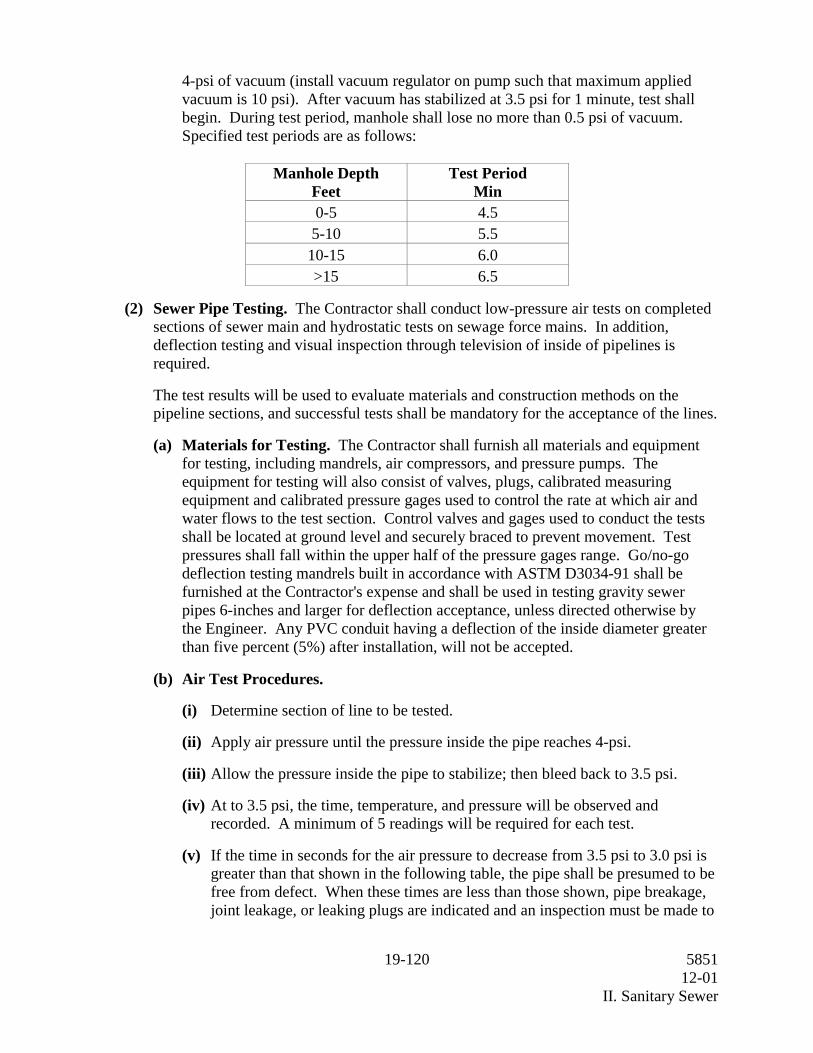
4-psi of vacuum (install vacuum regulator on pump such that maximum appliedvacuum is 10 psi). After vacuum has stabilized at 3.5 psi for 1 minute, test shallbegin. During test period, manhole shall lose no more than 0.5 psi of vacuum.Specified test periods are as follows:
Manhole DepthFeet
Test PeriodMin
0-5 4.55-10 5.510-15 6.0>15 6.5
(2) Sewer Pipe Testing. The Contractor shall conduct low-pressure air tests on completedsections of sewer main and hydrostatic tests on sewage force mains. In addition,deflection testing and visual inspection through television of inside of pipelines isrequired.
The test results will be used to evaluate materials and construction methods on thepipeline sections, and successful tests shall be mandatory for the acceptance of the lines.
(a) Materials for Testing. The Contractor shall furnish all materials and equipmentfor testing, including mandrels, air compressors, and pressure pumps. Theequipment for testing will also consist of valves, plugs, calibrated measuringequipment and calibrated pressure gages used to control the rate at which air andwater flows to the test section. Control valves and gages used to conduct the testsshall be located at ground level and securely braced to prevent movement. Testpressures shall fall within the upper half of the pressure gages range. Go/no-godeflection testing mandrels built in accordance with ASTM D3034-91 shall befurnished at the Contractor's expense and shall be used in testing gravity sewerpipes 6-inches and larger for deflection acceptance, unless directed otherwise bythe Engineer. Any PVC conduit having a deflection of the inside diameter greaterthan five percent (5%) after installation, will not be accepted.
(b) Air Test Procedures.
(i) Determine section of line to be tested.
(ii) Apply air pressure until the pressure inside the pipe reaches 4-psi.
(iii) Allow the pressure inside the pipe to stabilize; then bleed back to 3.5 psi.
(iv) At to 3.5 psi, the time, temperature, and pressure will be observed andrecorded. A minimum of 5 readings will be required for each test.
(v) If the time in seconds for the air pressure to decrease from 3.5 psi to 3.0 psi isgreater than that shown in the following table, the pipe shall be presumed to befree from defect. When these times are less than those shown, pipe breakage,joint leakage, or leaking plugs are indicated and an inspection must be made to

20-120 585112-01
II. Sanitary Sewer
determine the cause. The Contractor shall make repairs, as many as required toaccomplish a successful air test at his own expense.
Allowable Time Table
TimePipe Minute Second
4 inches 2 306 inches 4 08 inches 5 010 inches 6 3012 inches 7 3015 inches 9 30
(c) Hydrostatic Test Procedures.
(i) Isolate section of line to be tested by closing valves and installing temporaryplugs and bracing.
(ii) Slowly fill isolated section with clean water while relieving air from highpoints of the line.
(iii) Apply water pressure through high-pressure pump until the internal pipelinepressure reaches 150 psi.
(iv) Shut off pump and observe pressure.
(v) Repeat Steps 3 and 4 until pressure is stable at 150 psi.
(vi) Begin 60-minute test.
(vii)After 60 minutes, add water through high-pressure pump until 150 psi isreached.
(viii)If the volume of water required to reestablish the 150 psi internal pipelinepressure is less than or equal to 0.02 gallons per inch of nominal diameter per100 feet of length tested, then the pipeline shall be presumed free from defect.
When the leakage rate exceeds this rate, the Contractor shall make necessaryinspections to determine the cause of excessive leakage and make neededrepairs at his own expense.
(ix) Repeat steps 1 through 8 until each pipeline section passes.
(d) Television Inspection. Prior to placing lines into operation, completed sewer linesshall be inspected by Utility personnel with a television camera as a condition offinal acceptance of the installation. The Contractor shall thoroughly clean andflush all lines and notify the Utility Engineer that the line is ready for televisioninspection.
21-120 585112-01
II. Sanitary Sewer
Any defects discovered in the pipe or construction methods shall be corrected bythe Contractor at no additional cost to the Owner. The Owner will pay for theinitial TV inspection. Any additional inspection(s) required due to failure of theinitial inspection shall be paid for by the Contractor.
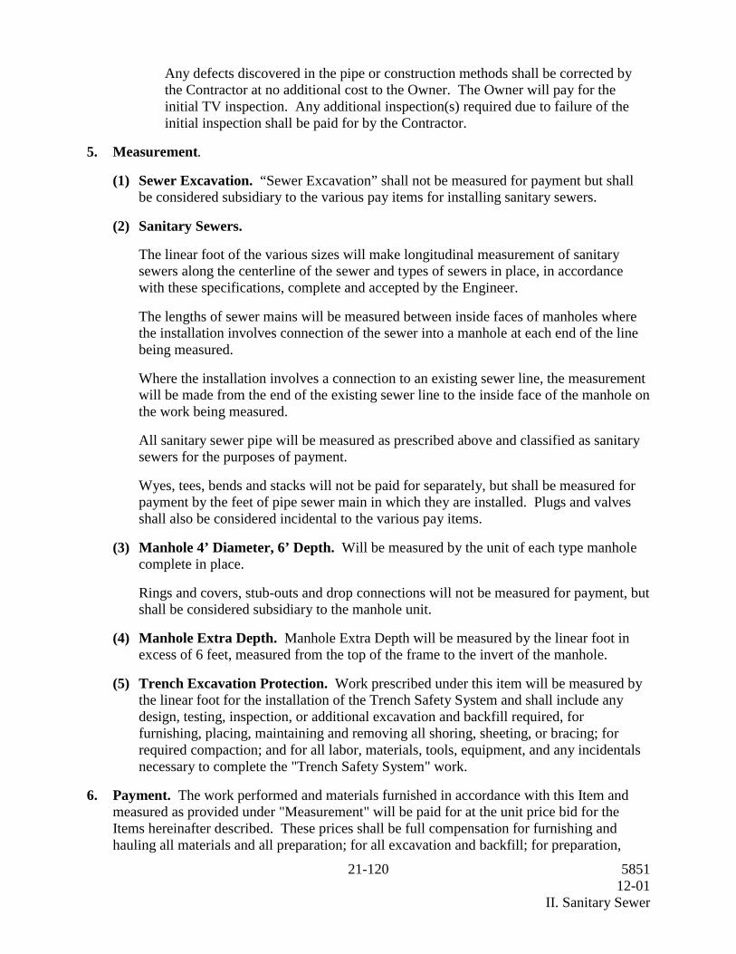
5. Measurement.
(1) Sewer Excavation. “Sewer Excavation” shall not be measured for payment but shallbe considered subsidiary to the various pay items for installing sanitary sewers.
(2) Sanitary Sewers.
The linear foot of the various sizes will make longitudinal measurement of sanitarysewers along the centerline of the sewer and types of sewers in place, in accordancewith these specifications, complete and accepted by the Engineer.
The lengths of sewer mains will be measured between inside faces of manholes wherethe installation involves connection of the sewer into a manhole at each end of the linebeing measured.
Where the installation involves a connection to an existing sewer line, the measurementwill be made from the end of the existing sewer line to the inside face of the manhole onthe work being measured.
All sanitary sewer pipe will be measured as prescribed above and classified as sanitarysewers for the purposes of payment.
Wyes, tees, bends and stacks will not be paid for separately, but shall be measured forpayment by the feet of pipe sewer main in which they are installed. Plugs and valvesshall also be considered incidental to the various pay items.
(3) Manhole 4’ Diameter, 6’ Depth. Will be measured by the unit of each type manholecomplete in place.
Rings and covers, stub-outs and drop connections will not be measured for payment, butshall be considered subsidiary to the manhole unit.
(4) Manhole Extra Depth. Manhole Extra Depth will be measured by the linear foot inexcess of 6 feet, measured from the top of the frame to the invert of the manhole.
(5) Trench Excavation Protection. Work prescribed under this item will be measured bythe linear foot for the installation of the Trench Safety System and shall include anydesign, testing, inspection, or additional excavation and backfill required, forfurnishing, placing, maintaining and removing all shoring, sheeting, or bracing; forrequired compaction; and for all labor, materials, tools, equipment, and any incidentalsnecessary to complete the "Trench Safety System" work.
6. Payment. The work performed and materials furnished in accordance with this Item andmeasured as provided under "Measurement" will be paid for at the unit price bid for theItems hereinafter described. These prices shall be full compensation for furnishing andhauling all materials and all preparation; for all excavation and backfill; for preparation,

22-120 585112-01
II. Sanitary Sewer
dewatering, shaping and fine grading the bottom of the trench; for cutting and restoration ofexisting streets, sidewalks, curbs, and driveways; for placing and joining of pipes andfittings; for stacks and manholes; and for all other Items of material, labor, equipment, toolsand incidentals necessary to complete the work in accordance with the plans andspecifications.
(1) Sewer Excavation. Payment for sewer excavation will not be paid for directly but shallbe considered subsidiary to the various pay Items for installing sewer mains. Paymentfor backfilling and compacting in accordance with these specifications will not be paidfor directly but shall be included in the unit price bid for "Sanitary Sewer".
(2) Sanitary Sewers. Payment for sanitary sewers, measured as prescribed above, will bemade at the bid unit price per linear foot for "Sanitary Sewers" of the size and typespecified, complete in place.
(3) Manhole 4’ Diameter Manhole Standard 6’ Depth. Work under this item includesfurnishing all labor, new materials and equipment and performing all operationsnecessary to construct the sanitary sewer manholes 6 feet or less in depth. Depth isdefined as the distance from the top of the cast iron frame to the invert of the sewer.This includes any extra excavation, backfill, concrete base, concrete or brick walls,conical section, frame and cover, providing an external protective coating such as coaltar epoxy, and any other facility or work necessary for the complete manhole, includingstub-outs and drop connections. Payment for manholes, including rings, covers, dropconnections, and steps, measured as prescribed above, shall be made at the bid unitprice for each "Manhole 4’ Diameter 6’ Depth" of the type specified.
(4) Manhole Extra Depth. Measured as provided under “Measurement”, will be paid forat the unit price bid for “Manhole Extra Depth”. Work under this Item includesfurnishing all labor, new materials and equipment, and performing all operationsnecessary to construct the depth of sanitary sewer manhole in excess of 6 feet; includingbut not limited to providing an external protective bituminous coating, such as coal tarepoxy.
(5) Trench Excavation Protection. Payment of all work prescribed under this Item shallbe full compensation for the Trench Safety System including any design, testing,inspection, or additional excavation and backfill required, for furnishing, placing,maintaining and removing all shoring, sheeting, or bracing; for required compaction;and for all labor, materials, tools, necessary to complete the "Trench ExcavationProtection" work. This Item will be measured and paid for by the bid unit price per footof Trench Safety System for sanitary sewers.
(6) Testing Sanitary Sewers for Leakage, including all labor, materials, and equipmentnecessary to perform the tests, will not be paid for directly but shall be consideredincidental to the various pay Items. Potable water utilized for testing, flushing, andfilling shall be provided at the Contractor's cost, as described in the specialspecifications portion herein.
(7) Traffic Control and Mobilization will not be paid for directly, but shall be consideredsubsidiary to the various bid Items.

23-120 585112-01
III. Water and Sanitary Sewer Bypassing and Dewatering
III. Water and Sanitary Sewer Bypassing and Dewatering
1. Description.
(1) Scope of Work. This section specifies the requirements for temporary bypassing,dewatering, flushing, and abandonment of water and sanitary sewer lines. TheContractor shall keep excavations reasonably free from water during construction. Thestatic water level shall be drawn down a minimum of 2 feet below the bottom ofexcavations to maintain the undisturbed state of natural soils and allow the placement ofany fill to the specified density. Disposal of water shall not damage property or create apublic nuisance. The Contractor shall have on-hand pumping equipment and machineryin good working condition for emergencies and shall have workmen available for itsoperation. Dewatering systems shall operate continuously until backfill has beencompleted to 1 foot above the normal static groundwater level.
Groundwater shall be controlled to prevent softening of the bottom of excavations, orformation of "quick" conditions. Dewatering systems shall not remove natural soils.The Contractor shall control surface runoff to prevent entry or collection of water inexcavations.
Release of groundwater to its static level shall be controlled to prevent disturbance ofthe natural foundation soils or compacted fill and to prevent flotation or movement ofstructures or pipelines.
(2) Requirements. The Contractor shall provide labor, materials, and supervision totemporarily bypass flow around the Contractor's work during water and sanitary sewerconstruction where necessary. The Contractor shall also provide temporary dewateringof low-lying portions of existing sanitary sewers as necessary. The Contractor shallflush all sanitary sewers and manholes to be abandoned with a minimum of twice thesanitary sewer's volume of water. The Contractor shall dewater all sanitary sewers andwater lines to be abandoned. Sanitary sewer lines to be abandoned shall be cut andplugged at all open ends. Water lines shall be isolated, valves closed and depressurizedprior to abandonment. All work to be closely coordinated with the Engineer.
(3) Submittals. Within 14 calendar days of notice to proceed, the Contractor shall submitto the Engineer for review and approval drawings and complete design data showingmethods and equipment he proposes to utilize in water and sanitary sewer bypassingand dewatering. The submittal shall include the following information:
(a) Drawings indicating the location of temporary water and sanitary sewer plugs andbypass discharge lines.
(b) Capacities of pumps, prime movers, and standby equipment.
(c) Design calculations proving adequacy of the system and selected equipment.
(4) Job Conditions.
(a) Available Data. Flow data are available for review at the Owner's office. Use ofthis information in no way relieves the Contractor from his responsibility fordesign, construction, and operation of an adequate and properly functioning bypass

24-120 585112-01
III. Water and Sanitary Sewer Bypassing and Dewatering
and dewatering system. Any additional testing or gathering of flow data is theresponsibility of the Contractor.
(b) Protection. Where bypassing or dewatering is required, the Contractor shallensure that service for connecting sanitary sewer laterals and water services is notdisrupted. All flow shall be discharged into the nearest downstream manhole.Bypassing and dewatering shall not surcharge sanitary sewers or interfere withnormal operation of related sanitary sewer facilities. No discharging to the groundsurface, receiving streams, storm drains, or discharging which results ingroundwater contamination or potential health hazards shall be permitted. In theevent accidental discharging is caused by the Contractor's operations, the Ownershall immediately be entitled to employ others to stop the discharging withoutgiving written notice to the Contractor. All water bypassing shall conform toAWWA procedures for prevention of contamination for water lines, backflowprovisions and provisions for conduit protection and support.
Penalties imposed on the Owner as a result of any discharge by the actions of theContractor, his employees, or sub-contractors, shall be borne in full by theContractor, including legal fees and other expenses to the Owner resulting directlyor indirectly from the discharge.
(c) Scheduling. The bypassing and dewatering systems shall not be shut downbetween shifts, on holidays or weekends, or during work stoppages without writtenpermission from the Engineer.
The Contractor shall submit a detailed outage plan and time schedule for operationsthat will make it necessary to remove a tank, pipeline, channel, electrical circuit,equipment or structure from service. The schedule shall be coordinated with theEngineer and shall meet the restrictions and conditions specified in this section.The detailed plan shall describe the Contractor's method for preventing accidentaldischarges, the length of time required to complete said operation, the necessaryplant, and equipment which the Contractor shall provide in order to preventaccidental discharges.
The Contractor shall observe the following restrictions:
Systems or individual equipment items shall be isolated, dewatered, decommissioned,de-energized, or depressurized in accordance with the detailed outage plan andschedule. The Engineer shall be notified in writing at least 1 week in advance of theplanned operation.
2. Products. No products are included in this section.
3. Execution.
(1) Water and Sanitary Sewer Dewatering. Contractor shall dewater all saggedsubmerged portions of the sanitary sewer during television inspection and grouting.Sanitary sewer flow shall be reduced so that no portion of the television camera's lens issubmerged during inspection. The Contractor may temporarily force the flow awayfrom the area under inspection by water jetting or piping the line. Where these methods

25-120 585112-01
III. Water and Sanitary Sewer Bypassing and Dewatering
cannot adequately reduce the flow, the Contractor shall either pump the flow fromwithin the sanitary sewer or water line or excavate the low portion of the line and pumpthe groundwater from below the pipeline. Sanitary sewers to be abandoned shall beflushed with two pipeline volumes of water prior to dewatering and abandoning.
(2) Water and Sanitary Sewer Bypassing.
General. Water and Sanitary sewer bypassing shall be accomplished by pumping ordiverting the upstream flow around the Contractor's work or as directed by theEngineer.
The Contractor shall provide temporary pumps, conduits, and other equipment tobypass the water or sanitary sewer flow. Contractor shall furnish the necessary laborand supervision to set up and operate the pumping and bypass system. Engines shall beequipped with mufflers and/or enclosed to keep the noise level within local ordinancerequirements. Pumps and bypass lines shall be of adequate capacity and size to handlethe flows. All bypassed flow shall be discharged to the nearest downstream manhole.
Unless otherwise specified, the Contractor shall bypass flow around his work wheneverthe depth of flow, as measured at the inlet pipe to the upstream manhole adjacent to theContractor's work, exceeds the crown elevation of the pipe; or whenever theContractor's equipment operating in the sanitary sewer provides an obstruction thatrestricts flow and causes the depth of flow to exceed the crown elevation.
(3) Standby Equipment.
The Contractor shall maintain on site sufficient equipment and materials to ensurecontinuous and successful operation of the bypass and dewatering systems. Standbypumps shall be fueled and operational at all times. The Contractor shall maintain onsite a sufficient number of valves, tees, elbows, connections, tools, sanitary sewer plugs,piping and other parts or system hardware to ensure immediate repair or modification ofany part of the system as necessary.
(4) Damages.
The Contractor shall repair without cost to the Owner any damage that may result fromhis negligence, inadequate or improper installation, maintenance and operation ofbypassing and a dewatering system including mechanical or electrical failures.
(5) Measurement and Payment.
Payment for the work in this section will be subsidiary to the unit prices for installingpipe, manholes, valves, or fittings, complete in place.
26-120 585112-01
IV. Excavation and Backfill for Structures and Pipelines
IV. Excavation and Backfill for Structures and Pipelines
For this project, Item 400, "Excavation and Backfill for Structures", of the StandardSpecifications, is hereby amended with respect to the clauses cited below and no otherclauses or requirements of this Item are waived or changed hereby.
Article 400.1 Description is voided and replaced by the following:
Article 400.1. Description. This item shall govern for the excavation, bedding, backfilland/or Portland cement stabilized backfill required for the construction of all structures,except drilled shafts. This Item shall also govern for any necessary sloping, pumping orbailing, for drainage, flushing, bypassing, dewatering, and for all sheeting and bracing ofexcavation walls up to 5 feet in depth. Excavation greater than 5 feet in depth shall beprotected as specified in Item 402, "Trench Excavation Protection" or Item 403, "TemporarySpecial Shoring." Unless otherwise provided, the work included herein shall provide for theremoval of old structures or portions thereof (abutments, wingwalls, piers, housefoundations, old sanitary and storm sewers, sanitary and storm sewer appurtenances, etc.),trees and all other obstructions to the proposed construction, the blocking of the ends ofabandoned water and sanitary sewers cut and left in place, the blocking of valves, fittingsand appurtenances, and the protection of existing utilities. Also governed by this Item arethe cutting and restoration of pavement and base courses, the construction and removal ofany cofferdams, the hauling and disposition of surplus materials and the bridging of trenchesand other provisions for maintenance of traffic or access.
Article 400.2. Excavation, Subarticle (1) General, Section (c) Protection of Utilities issupplemented by the following:
Where bypassing is necessary to construct sanitary sewers, the Contractor shall providetemporary pumps, conduits, plugs, and other equipment to bypass the sanitary sewer flow.The Contractor shall furnish the necessary labor and supervision to set up and continuouslyoperate the pumping and bypass system. Engines shall be equipped with mufflers and/orenclosed to keep the noise level within local ordinance requirements. Standby equipmentand materials shall be maintained at the project site to ensure continuous and successfuloperation of the bypass and dewatering systems, as described in these SpecialSpecifications.
Where bypassing or dewatering is required, the Contractor shall ensure that service forconnecting laterals is not disrupted. All flow shall be discharged into the nearestdownstream manhole. Bypassing and dewatering shall not surcharge sanitary sewers orinterfere with normal operation of related sanitary sewer facilities. No discharging to theground surface, receiving streams, storm drains, or discharging which results in groundwatercontamination or potential health hazards shall be permitted. In the event accidentaldischarging is caused by the Contractor's operations, the Engineer shall immediately beentitled to employ others to stop the discharging without giving written notice to theContractor.
Penalties imposed on the State or any utility entity as a result of any discharge by theContractor, his employees, or Subcontractors, shall be borne in full by the Contractor,including legal fees and other expenses resulting directly or indirectly from the discharge.

27-120 585112-01
IV. Excavation and Backfill for Structures and Pipelines
Article 400.2. Excavation, Subarticle (1) General, Section (d) Removing OldStructures or Abandoned Structures is supplemented by the following:
Sanitary sewers and manholes to be abandoned, as shown on the plans, shall be dewateredand flushed with two pipeline volumes of water prior to final dewatering, plugging andabandoning. Dewatering flows shall be discharged into the nearest downstream manhole,but shall not surcharge sanitary sewers or interfere with the normal operation of relatedsanitary sewer facilities.
Any water and sanitary sewer mains to be abandoned under the project drawings that arefound to be in conflict with any proposed structure, water line, sanitary sewer line, stormsewer, foundation assembly, shall be removed by the Contractor at his expense and isconsidered subsidiary to the various bid Items for water and sanitary sewer line installation.
Article 400.2. Excavation, Subarticle (1) General, Section (e) Dewatering ofExcavation Area is voided and replaced by the following:
Dewatering Excavation. Structures shall not be constructed or laid in the presence of waterunless approved by the Engineer. Setting of pre-cast members, placement of concrete, orpipe placing operations shall be performed on a dry firm bed. This shall be accomplished byremoval of water from the surface of the bed by bailing, pumping, well-point installation,deep wells, french drains, or any other method approved by the Engineer and as described inthis specification. The excavation shall be maintained in such dewatered condition until allconcrete and mortar is set and until backfill has been completed to one foot above thenormal static groundwater level. Disposal of water shall not damage property or create apublic nuisance. Disposal of groundwater into the sanitary sewer system shall not beallowed, unless otherwise directed by the Engineer. The Contractor shall maintain pumpingequipment and machinery in good working condition for emergencies and shall haveworkers available for its operation. Release of groundwater to its static level shall becontrolled to prevent disturbances to surrounding soils, fills, structures, and pipelines.
For foundations placed in the presence of water, when approved by the Engineer, pumpingor bailing from the interior of any foundation enclosure shall be done in a manner whichprecludes the possibility of movement of water through or alongside any concrete beingplaced. No pumping or bailing will be permitted during the placing of structural concrete orfor a period of at least 36 hours thereafter, unless from a suitable sump separated from theconcrete work. Pumping or bailing during placement of seal concrete shall be only to theextent necessary to maintain a static head of water within the cofferdam. Pumping orbailing to dewater a sealed cofferdam shall not be started until the seal has aged at least 36hours.
In the event that the excavation cannot be dewatered to the point where the subgrade is freeof mud, or it is difficult to keep the reinforcing steel clean in cast-in-place structures, aspecial material shall be used in the bottom of the excavation. Such special material shall bea minimum depth of 3 inches and shall consist of a lean concrete mixture with not less thanfour (4) sacks of cement per cubic meter (three (3) sacks of cement per cubic yard), or othermaterial approved by the Engineer.

28-120 585112-01
IV. Excavation and Backfill for Structures and Pipelines
Article 400.4. Shaping and Bedding is voided (with the exception of figures 1, 2, and 3)and replaced by the following:
Article 400.4. Shaping and Bedding. For pre-cast pipe, box sections and all PVC pipe, theexcavation shall be undercut a minimum depth sufficient to accommodate the Class ofbedding indicated on the plans and conforming to the bedding requirements of this Item.Where cement stabilized backfill is indicated on the plans, the excavation shall be undercut aminimum of 4 inches and backfilled with stabilized material to support the pipe at therequired grade.
Three Classes of bedding for trench embankment conditions are shown in Figures 1, 2, and3. Bedding shall be in accordance with Class C bedding unless otherwise shown on theplans. The Engineer may require the use of a template to secure reasonably accurateshaping of the foundation material.
The Contractor shall not proceed with PVC bedding until the Engineer has inspected thesubgrade. All pipes shall have a minimum thickness of bedding material below the barrel ofthe pipe as shown. Bedding material shall be placed in the bottom of the trench, leveled,and compacted. Bell holes shall be excavated at each pipe joint to permit proper inspectionand uniform bearing of pipe on bedding material.
Article 400.5. Backfill, Subarticle (3) Pipe is supplemented by the following:
All PVC pipe shall be bedded and backfilled with the following material as shown on theplans. The material shall be a clean gravel-sand mixture free from organic matter andconforming to the following graduation:
Standard Sieve SizePercent by
Weight Passing3/4 inch 1003/8 inch 70-100
No. 4 55-100No. 10 35-95No. 20 20-80No. 40 10-55No. 100 0-2
PVC backfill shall be compacted to a minimum 95 percent by Test Method TEX-115-E forfield densities.

29-120 585112-01
IV. Excavation and Backfill for Structures and Pipelines
Article 400.7. Measurement is supplemented by the following:
(18) The work done to perform necessary excavation dewatering, sanitary sewer dewatering,flushing and abandonment of mains and manholes, and bypassing is considered incidental tothe other work performed and will not be measured separately.

30-120 585112-01
V. Grout
V. Grout
1. Description. This section specifies grout uses other than masonry.
(1) Quality Assurance.
(a) Quality Control by Contractor. To demonstrate conformance with the specifiedrequirements for grout, the Contractor shall provide the services of an independenttesting laboratory that complies with the requirements of ASTM E329. The testinglaboratory shall sample and test grout materials as required in this section. Costs oftesting laboratory services shall be borne by the Contractor.
(b) References. This section contains references to the following documents. Theyare a part of this section as specified and modified. In case of conflict between therequirements of this section and those of the listed documents, the requirements ofthis section shall prevail.
Reference TitleASTM C33-86 Concrete AggregatesASTM C40-84 Organic Impurities in Fine Aggregates for ConcreteASTM C88-83 Soundness of Aggregates by Use of Sodium Sulfate
or Magnesium SulfateASTM C117-87 Material Finer Than 75-um (No. 200) Sieve in
Mineral Aggregates by WashingASTM C136-84a Sieve Analysis of Fine and Coarse AggregatesASTM C150-89 Portland CementASTM C289-87 Potential Reactivity of Aggregates (Chemical
Method)ASTM C494-86 Chemical Admixtures for ConcreteASTM C881-87 Epoxy-Resin-Base Bonding Systems for ConcreteASTM D2419-74 Sand Equivalent Value of Soils and Fine AggregateASTM E329-77 Inspection and Testing Agencies for Concrete, Steel,
and Bituminous Materials as Used in ConstructionCRD-C621-82B Corps of Engineers Specification for Non-shrink
Grout
2. Products.
(1) Materials.
(a) Cement. Portland Cement shall be ASTM C150, Type II or Type V, low alkali,containing less than 0.60 percent alkalis.

31-120 585112-01
V. Grout
(b) Aggregate.
General. Aggregate shall be non-reactive and shall be washed before use.
When sources of aggregate are changed, test reports shall be provided for the newmaterial. The tests specified shall be performed prior to commencing grout work.
(c) Fine Aggregate. Fine aggregate shall be hard, dense, durable particles of eithersand or crushed stone regularly graded from coarse to fine and shall conform toASTM C33 as modified herein. When tested in accordance with ASTM C136,gradation shall be such that 100 percent by weight will pass a standard No. 8 meshsieve and no less than 45 percent by weight will pass a standard No. 40 mesh sieve.
Variation from the specified gradations in individual tests will be acceptable if theaverage of three consecutive tests is within the specified limits and the variation iswithin the permissible variation listed below:
U.S. StandardSieve Size
Permissible Variation inIndividual Tests, Percent
30 or coarser 250 or finer 0.5
Other tests shall be in accordance with the following specifications:
Test Test Method Requirements
Organic Impurities ASTM C40 Color lighter thanstandard
Amount of MaterialPassing No. 200Sieve 3% maximumby weight
ASTM C117
Soundness 10%maximum loss withsodium sulfate ASTM C88
ReactivityInnocuousaggregate ASTM C289
Sand Equivalent ASTM D2419 Minimum 80

32-120 585112-01
V. Grout
(d) Admixtures.
(i) General. Admixtures shall be compatible with the grout.Calcium chloride or admixtures containing calcium chloride are notacceptable. Admixtures shall be used in accordance with the manufacturer'srecommendations and shall be added separately to the grout mix.
(ii) Water Reducing Retarder. Water reducing retarder shall be ASTM C494,Type D and shall be Master Builders Pozzolith 300-R, Sika CorporationPlastiment, or equal.
(iii) Lubricant for Cement Pressure Grouting. Lubricant additive for cementpressure grouting shall be Intrusion Prepakt Intrusion Aid, Sika Intraplast N, orequal.
(e) Water. Water for washing aggregate, for mixing and for curing shall be free fromoil and deleterious amounts of acids, alkalies, and organic materials; shall notcontain more than 1000 mg/L of chlorides as Cl, nor more than 1300 mg/L ofsulfates as SO4; and shall not contain an amount of impurities that may cause achange of more than 25 percent in the setting time of the cement nor a reduction ofmore than 5 percent in the compressive strength of the grout at 14 days whencompared with the result obtained with distilled water. Additionally, water usedfor curing shall not contain an amount of impurities sufficient to discolor the grout.
(2) Grout.
(a) Drypack Grout. Drypack grout shall be a mixture of approximately one partcement, 1-1/2 to 2 parts sand, water reducing retarder, and sufficient water to makea stiff workable mix.
(b) Cement Grout. Cement grout shall be a mixture of one part cement, two partssand, proportioned by volume, admixtures for pressure grouting, and sufficientwater to form a workable mix.
(c) Non-shrink Grout.. Non-shrink grout is available with both metallic andnonmetallic aggregate. Metallic aggregate grout shall be Master Builders Embeco636, Burke Company Metallic Spec Grout, Sonnoborn Ferrolith G Redimix, orequal. Nonmetallic aggregate grout shall be U.S. Grout Corp. Five Star grout,Master Builders Masterflow 713, Burke Company Non-Ferrous, Non-Shrink Grout,or equal.
(d) Epoxy Grout for Crack Repair and Dowel Anchorage. Except as noted below,epoxy grout shall be a high modulus, two-component, moisture insensitive, 100percent solids, thermosetting modified polyamide epoxy compound. Theconsistency shall be a paste form capable of not sagging in horizontal or overheadanchoring configurations. Material shall conform to ASTM C881, Type 1, Grade3, such as Adhesive Engineering Concresive 1440 series, Sika Corporation SikadurHi-Mod Series, Adhesive Technology Corporation Solidbond 200 or equal, andshall have a heat deflection temperature in excess of 130°F.

33-120 585112-01
V. Grout
Epoxy for pressure grouting/crack injection shall be a two-component, moistureinsensitive, high modulus, injection grade, 100 percent solids, blend of epoxy-resincompounds. The consistency shall be as required to achieve complete penetrationin hairline cracks and larger. Material shall conform to ASTM C881, Type 1Grade 1, such as Sika Corporation Sikadur 52, Adhesive Engineering CompanySCB products, Adhesive Technology Corporation SLV 300 series, or equal.
(e) Polymer Concrete (for resurfacing or patching). Polymer concrete (forresurfacing or patching) shall consist of a liquid binder and dry aggregate mixedtogether to make a flowable mortar or grout. The liquid binder shall be a chemicaland oil resistant, stress relieved, low modulus, moisture insensitive, two-componentepoxy-resin compound. The consistency shall be similar to lightweight oil forproper mixing with aggregate. Material shall conform to ASTM C881, Type 3Grade 1, such as Sika Corporation Sikadur Lo-Mod series, Adhesive EngineeringConcresive 1470, Adhesive Technology Corporation 400 series, or equal.
The aggregate shall be oven dry in sealed packages until time of mixing, and shallbe of size and consistency compatible with recommendations of manufacturer ofliquid binder for intended application.
(f) Adhesive Capsules for Dowel Anchorage: Adhesive resin capsules shall consistof sealed glass capsules containing pre-measured amounts of a polyester orvinylester resin, quartz sand aggregate and a hardener contained in a separate vialwithin the capsule. Adhesive capsules shall be Hilti HEA Capsules, MollyParabond Capsules, or equal.
(3) Pressure Grouting Equipment. Pressure grouting equipment shall include a mixerand holdover agitator tanks and shall be designed to place grout at pressures up to 50psi. Gages shall be provided to indicate pressure used. The mixer shall be providedwith a meter capable of indicating to one-tenth of a cubic foot the volume of grout used.
(4) Product Data. The following information shall be provided:
(a) Manufacturer's Data. Manufacturer’s data shall be provided for the following:
1. Bonding compounds2. Non-shrink grout3. Pressure grout4. Retardants5. Epoxy grout6. Polymer concrete
(b) Laboratory Test Reports. Test reports on previously tested materials shall beaccompanied by the manufacturer's statement that the previously tested material isthe same type, quality, manufacture, and make as that proposed for use in thisproject. Test reports are required for the following:
(a) Cement(b) Aggregates(c) Retardants
34-120 585112-01
V. Grout
(d) Bonding compounds(e) Epoxy resin
(c) Evidence of Testing Laboratory Competence. The Contractor shall require thatthe laboratory provide directly to the Engineer evidence of the most recentinspection of its facilities by the Cement and Concrete Reference Laboratory of theNational Bureau of Standards. The evidences shall show that deficienciesmentioned in the report of that inspection have been corrected. The evidence ofinspection shall be provided prior to delivery of materials to the job site.
3. Execution.
(1) General. Primer, if required for polymer concrete, shall be provided per manufacturer'srecommendation.
(2) Drypack Grout. Drypack grout shall be used for built-up surfaces, settingmiscellaneous metal items and minor repairs.
Surfaces required to be built up with drypack grout shall be roughened by brushing,cleaned, and coated with a bonding compound before the application of the grout. Thedrypack grout shall be applied immediately following the application of the bondingcompound in bands or strips to form a covering of the required thickness. The coveringshall be smooth. Construction joints in the grout shall be sloped and shall be cleanedand wetted before application is resumed.
Grout shall not be placed during freezing weather unless adequate protection isprovided.
(3) Cement Grout. Cement grout shall be used for filling rip rap voids, nonbearingportions of equipment pads, and pressure grouting.
Except for the specialized equipment for pressure grouting, mixing and placingapparatus shall be similar to that normally used for cast-in-place concrete. Grout shallbe mixed for a period of at least 1-minute. Diluted grout shall be agitated to keepingredients mixed.
(4) Non-shrink Grout. Non-shrink, nonmetallic aggregate grout shall be used for thebearing surfaces of machinery and equipment bases, column base plates and bearingplates. Non-shrink metallic aggregate grout shall be used for setting anchor bolts andgrouting reinforcing steel holes. Grout shall meet the requirements of CRD-C621 andshall be placed in accordance with manufacturer's instructions.
Holes required for grouting shall be blown clean with compressed air and left free ofdust or standing water. Horizontal holes for grouting shall be drilled at a slightdownward angle to facilitate holding the grout until setting is complete. Bolts orreinforcing steel installed in horizontal grout holes shall be bent slightly accordingly.
(5) Epoxy Grout. Epoxy grout shall be used for repairing cracks by pressure grouting orgravity flow, repairing structural concrete, and may be used for setting reinforcing
35-120 585112-01
V. Grout
dowels or anchor bolts into holes for grouting. Concrete shall be primed in accordancewith the grout manufacturer's instructions.
Use of epoxy grout for anchorage of bolts or reinforcing dowels shall be subject to thefollowing conditions:
(a) Use shall be limited to locations where exposure, on an intermittent or continuousbasis, to acid concentrations higher than 10 percent, to chlorine gas, or to machineor diesel oils, is extremely unlikely.
(b) Use shall be limited to applications where exposure to fire or exposure to concreteor rod temperature above the product's heat deflection temperature or 120°F(whichever is less) is extremely unlikely. Overhead applications (such as pipesupports) because of the above concerns shall be disallowed.
(c) Approval from the Engineer for specific application and from supplier ofequipment to be anchored, if applicable.
(d) Anchor diameter and grade of steel shall be per contract documents or perequipment supplier specifications. Anchor shall be threaded or deformed fulllength of embedment and shall be free of rust, scale, grease, and oils.
(e) Embedment depth and hole diameter shall be as specified.
(f) Holes shall have rough surfaces, such as can be achieved using a rotary percussiondrill.
(g) Holes shall be blown clean with compressed air and be free of dust or standingwater prior to application of grout.
(h) Anchor shall be left undisturbed and unloaded for full curing period.
(i) Anchors shall not be placed in concrete below 25°F.
(6) Adhesive Capsules. Adhesive resin capsules may be used for setting and anchoringreinforcing dowels or anchor bolts into predrilled holes in concrete.
(7) Pressure Grouting. Prior to grouting, systems and holes to be grouted shall be washedclean. Washing is not required for grouting soil voids outside pipe cylinders or casingpipes. Grouting, once commenced, shall be completed without stoppage. In case ofbreakdown of equipment, the Contractor shall wash out the grouting system sufficientlyto ensure fresh grout and adequate bond and penetration will occur upon restarting thegrouting operation. Grout pressure shall be maintained until grout has set.
(8) Measurement and Payment. Payment for the work in this section will be subsidiaryto the unit prices for installing pipe, valves, fittings, concrete collars and/or saddles,manholes, or abandonment of manholes, complete in place.
36-120 585112-01
VI. Piping Systems
VI. Piping Systems
1. General.
(1) Description.
(a) Scope. This section specifies systems of process piping and general requirementsfor piping systems. Detailed specifications for the components listed on the PipingSystem Specification Sheets are found in other Special Specification Sections.This section shall be used in conjunction with those sections.
(b) Definitions. Pressure terms used in this specification and elsewhere are defined asfollows:
(i) Maximum. The greatest continuous pressure at which the piping systemoperates.
(ii) Test. The hydrostatic pressure used to determine system acceptance.
(2) Quality Assurance.
(a) References. This section contains references to the following documents. Theyare a part of this section as specified and modified. In case of conflict between therequirements of this section and those of the listed documents, the requirements ofthis section shall prevail.
Reference Title
ANSI B1.20.1-83 Pipe Threads, General Purpose (Inch)ANSI B16.1-89 Cast Iron Pipe Flanges and Flanged Fittings Class 25,
125, 250, and 800ANSI B16.5-88 Pipe Flanges and Flanged FittingsANSI B16.22-80 Wrought Copper and Copper Alloy Solder Joint
Pressure FittingsASTM A536-84 Ductile Iron CastingsASTM B88-89 Seamless Copper Water TubeASTM D1784-81 Rigid Poly Vinyl Chloride (PVC) CompoundsASTM D1785-89 Poly Vinyl Chloride (PVC) Plastic Pipe, Schedules
40, 80, and 120ASTM D3034-89 Poly Vinyl Chloride (PVC) Sewer Pipe and FittingsASTM F477-76 Elastomeric Seals (Gaskets) for Joining Plastic Pipe
and FittingsASTM F679-89 Poly Vinyl Chloride (PVC) Large-diameter Plastic
Gravity Sewer Pipe and FittingsAWWAC105/A21.5
Polyethylene Encasement for Ductile-Iron Piping forWater and Other Liquids
AWWA C110-87 Ductile-Iron and Gray-Iron Fittings, 3-inch through48-inch for Water and Other Liquids

37-120 585112-01
VI. Piping Systems
Reference Title
AWWA C111-85 Rubber-Gasket Joints for Ductile-Iron and Gray-IronPressure Pipe and Fittings
AWWA C115-88 Flanged Ductile-Iron and Gray-Iron Pipe withThreaded Flanges
AWWA C151-86 Ductile-Iron Pipe, Centrifugally Cast in Metal Moldsor Sand-Lined Molds, for Water or Other Liquids
AWWA C205-89 Cement-Mortar Protective Lining and Coating forSteel Water Pipe 4-inch and Larger – Shop Applied
AWWA C209-84 Cold-Applied Tape Coating for Special Sections,Connections, and Fittings for Steel Water Pipelines
AWWA C214-83 Tape Coating Systems for the Exterior of Steel WaterPipelines
AWWA C600-87 Installation of Ductile-Iron Water Mains and theirAppurtenances
AWWA C651-86 Disinfecting Water MainsAWWA C900-89 Polyvinyl Chloride (PVC) Pressure Pipe, 4 inches
through 12 inches for WaterAWWA M11-85 Steel Pipe--A Guide for Design and InstallationFEDSPEC L-C- Coating, Pipe, Thermoplastic Resin or 530B(1)-72
Thermosetting EpoxyUPC (1988) Uniform Plumbing Code
(b) Fittings and Coupling Compatibility. To assure uniformity and compatibility ofpiping components, fittings, and couplings for grooved end piping systems shall befurnished by the same manufacturers.
2. Products.
(1) Piping Materials. Unless otherwise specified, piping materials, including pipe,gaskets, fittings, connection and joint assemblies, linings and coatings, shall be selectedfrom those listed on the piping system specification sheets. Piping materials shallconform to detailed specifications for each type of pipe and piping appurtenancespecified in other sections.
(2) Piping Identification.
(a) Plastic Coding Markers. Not used
(b) Plastic Tracer Tape. Water, Reclaim Water, and Sanitary Sewer pipe shall bemarked by concurrently installing the appropriate marking tape for detectionpurposes. The detectable tape shall consist of a 5.0-mil inert polyethylene plasticmaterial. It shall be high visibility blue for potable water, purple for reclaim water,and green for sanitary sewer with the standard warning and identification imprintedon the tape. The minimum width of detectable tape shall be 2 inches for 8-inchmain lines and smaller and 6 inches for larger potable water or sanitary sewer mainlines. For PVC services 3 inches and larger, width shall be a minimum of 6 inches

38-120 585112-01
VI. Piping Systems
or twice the line diameter. Detecting tape shall be manufactured by ThorEnterprises, “Magnatec”, or approved equal.
(3) Valves. A single valve manufacturer shall provide all same-size valves and all valvesfor the same service. Packing shall be non-asbestos material. Actual length of valvesshall be within 1/16 inch of the manufacturer's specified length. Flanges shall meet therequirement of ANSI B16.5. Push-on and mechanical joints shall meet therequirements of AWWA C111. Valve operators are specified in this specification.
(4) Product Data. Complete shop drawings and specifications on piping materials andvalves shall be furnished to the Owner for acceptance and approval 2 weeks prior toproceed with their installation. The valve manufacturer shall furnish a complete set ofinstallation, operation, and maintenance instructions for each type of valve furnished.Instructions shall be bound in a cover.
3. Execution.
(1) Installation.
(a) Location. Piping shall be provided as specified on the drawings except foradjustments to avoid existing or planned utilities and/or other structures and shallbe coordinated with road construction.
(b) Piping Sizes. Where the size of piping is not specified, the Contractor shallprovide piping of the sizes required by UPC. Unless specified otherwise, smallpiping (less than 1 inch in diameter) required for services not described by UPCshall be 3/4 inches.
(c) Pipe Support, Anchorage and Seismic Bracing. Not used
(d) Anchorage for Buried Piping. All plugs, caps, tees, valves, and bends in buriedpressure piping systems shall be anchored by means of reaction backing orrestrained joints as specified in the plans.
(e) Bedding and Backfill. Bedding and backfill for buried piping shall be as specifiedin the plans.
(2) Piping Identification.
(a) Pipe Coding. Not used
(b) Plastic Tracer Tape. A single line of tape as specified in paragraph 2.(2).(b) ofthis section shall be provided. The maximum burial depth shall be 18 inches forthe 2 inch wide and 36 inches for the 6 inch wide tape, measured from finishedgrade. For PVC services 3 inch and larger, the burial depth shall not exceed 36inches below the final grade nor be at an elevation of less than 12 inches above theutility line. For pipelines buried 8 feet or greater below finished grade, TheContractor shall provide a second line of tape 12 inches below finished grade,above and parallel to each buried pipe. Tape shall be spread flat with message sideup before backfilling.

39-120 585112-01
VI. Piping Systems
(3) Valve Identification. Potable water main system valves shall be as specified on thedrawing documents. Reclaim water main system valves shall be as specified on thedrawing documents.
(4) Testing.
(a) General. Upon completion of piping the Contractor shall clean, sterilize andpressure-test the piping systems. Pressures, media and test duration shall be asspecified in Special Specifications Section I, (pg. 4-123), “Water Mains andReclaim Water Mains”. Equipment that may be damaged by the specified testconditions shall be isolated. Testing shall be performed using calibrated test gagesand calibrated volumetric measuring equipment to determine leakage rates. Eachtest gage shall be selected so that the specified test pressure falls within theupper half of the gage's range. The Contractor shall provide all testing apparatusincluding pumps, compressors, hoses, gauges and fittings, and other equipmentnecessary to perform the required tests. The Contractor shall notify the Engineer48 hours prior to each test.
Unless otherwise specified, testing shall include existing piping systems thatconnect with new pipe systems. Existing pipe shall be tested to the nearest existingvalve. Any piping which fails the test shall be repaired and re-tested. Repair ofexisting piping as a result of required tests will be considered and paid for as extrawork and in accordance with bid measurement and payment.
(b) Gas, Air, and Vapor Systems. Not used
(c) Liquid Systems. Unless otherwise specified, leakage from buried liquid pipingsystems shall be less than 0.02 gallon per hour per inch diameter per 100 feet ofburied piping.
(5) Cleaning and Flushing.
(a) General. Piping systems shall be cleaned following completion of testing andprior to connection to operating, control, regulating, or instrumentation equipment.The Contractor may, at his option, clean and test sections of buried or exposedpiping systems. Use of this procedure, however, will not waive the requirement fora full pressure test of the completed system. Unless specified otherwise, piping 24in. in diameter and smaller shall first be cleaned by pulling a tightly fitting cleaningball or swab through the system. Piping larger than 24 in. in diameter may becleaned manually or with a cleaning ball or swab.
(b) Temporary Screens. Not used
(c) Gas and Air Systems. Not used
(d) Liquid Systems. After completion of cleaning, liquid systems, unless otherwisespecified, shall be flushed with clean water.
(e) Potable Water Systems. Potable water piping systems and reclaim water pipingsystems shall be flushed and disinfected in accordance with AWWA C651.

40-120 585112-01
VI. Piping Systems
(6) Piping Specification Sheets (PIPESPEC). Piping and valves for groupings of similartypes of service lines are specified on individual piping specification sheets(PIPESPECS). Piping services are grouped according to the chemical and physicalproperties of the fluid conveyed and/or by the temperature or pressure requirements.Each grouping of services (PIPESPEC) is identified by a piping system number. Pipingservices specified in the PIPESPECS and on the drawings are alphabetically arrangedby designated service symbols as shown in Table A. Table A also indicates the systemnumber, fluid category, and pipe marker background color of each service.
Table APiping Services
Pipe MarkerBackgroundSymbol
FluidService System
Category ColorW Potable Water 7 Water Blue
SGravity RawSewage 24 Wastewater Green
Piping Symbol/Service W--Potable Water System--7
Test Requirements:Medium: Water and Reclaim Water; reference this Specification,
paragraph 3.(4).(c).Pressure: 150 psigDuration: 60 minutes
Gasket Requirements:Flange: Compressed gasketing consisting of organic fibers (Kevlar)
and neoprene binderPush-on/MechanicalCoupling:
Nitrile or Neoprene
(7) Buried and Encased Pipe and Valves.(See drawings for pipe size and valve type. Omit coating on encased pipe.)
Polyethylene wrap shall be standard protection for ductile iron pipe and fittings lessthan 36-inch in diameter. The polyethylene wrap shall be applied in accordance withAWWA C-105/A21.5, except that minimum thickness shall be 30 mils.
41-120 585112-01
VI. Piping Systems
3-inch and smaller:Pipe: Copper tube: ASTM B88, Type K, annealed or drawn. Conn;
solder type, with threaded or flanged adapters for valves. Ftgs;wrought copper or bronze, ANSI B16.2.2
Valves: Gate: reference this specification, with extension stem and valvebox. Coating: polyethylene wrap, 30 mil minimum
4-inch thru 12-inch:Pipe: PVC: AWWA C900 (DR18). Reference this specification.
Provide plastic tracer tape.Conn; Push-on elastomeric rubber gasket joint.Ftgs; ductile iron per AWWA C110-87; Coating, M1plus polyethylene bagging (30-mil minimum), cementmortar lining, and ends to match pipe.
Valves: Gate: Reference this specification, with extension systemand valve box. Coating M1 per this specification, pluspolyethylene bagging (30-mil minimum).
PipingSymbol/Service:
S--RawSewage(GravityFlow)
System--24
Test Requirements:
Medium: In accordance with Section 318, Uniform Plumbing Code, ASTMC-828 Recommended Practice for Low-Pressure Air Test ofVitrified Clay Pipe Lines 4 inch to 12 inch.
ASTM C-1103 Standard Practice for Joint Testing of Installed Pre-Cast ConcretePipe Sewer Lines.
ASTM D-3034 Specification for Poly Vinyl Chloride (PVC) Sewer Pipe and Fittings.
ASTM F-679 Specification for Poly Vinyl Chloride (PVC) Large-Diameter PlasticGravity Sewer Pipe and Fittings.
UNI-BELL-6 Standards and Practices for Low-Pressure Air Testing of Installed SewerPipe.
UNI-BELL-9 Poly Vinyl Chloride (PVC) Large Diameter Gravity Sewer Pipe andFittings Based on Controlled Inside Diameter(Nominal Pipe Sizes 18 inch – 48 inch).
ManufacturedProducts:
Contractor shall provide all testing apparatus including pumps,compressors, hoses, gauges and fittings, mandrels, and other equipmentnecessary to perform the required tests.
42-120 585112-01
VI. Piping Systems
ASTM D-3034 Specification for Poly Vinyl Chloride (PVC) Sewer Pipe and Fittings.
TelevisionInspection:
Prior to placing lines into operation, completed sewer lines shall beinspected twice by Utility personnel with a television camera; the first,upon completion of the sewer line installation; the second, uponcompletion of the roadway construction as a condition of final acceptanceof the installation. The Contractor shall thoroughly clean and flush alllines and notify the Utility Engineer that the line is ready for televisioninspection.The Contractor at no additional cost to the Owner shall correct any defectsdiscovered in the pipe or construction methods. The Owner will pay forthe initial TV inspections. The Contractor shall pay for any additionalinspection(s) due to failure of the initial inspection.
Pressure: In accordance with Section 318, Uniform Plumbing Code.Duration: In accordance with Section 318, Uniform Plumbing Code.
GasketRequirements:
Flange: Compressed gasketing consisting of organic fibers (Kevlar) and neoprenebinder
Push-on/MechanicalCoupling:
Nitrile or Neoprene
(8) Buried and Encased Pipe and Valves.(See drawings for pipe size 15-inch and smaller.)
Pipe: PVC: ASTM D3034, SDR 35 (except as specified directly onthe plans for ductile iron pipe Class 52). Reference thisspecification. Provide plastic tracer tape.Conn; Push-on with nitrile gasket.Ftgs; PVC, or IPS cast iron; ends to match pipe
Valves: None
(9) Water for Construction: Refer to these Specifications.
43-120 585112-01
VII. Steel Casing and Carrier Pipe Installation
VII. Steel Casing and Carrier Pipe Installation
1. General.
(1) Description. The Contractor shall install casings at the locations and to the lines andgrades indicated on the Plans, of the sizes indicated, using either jacking, boring,tunneling, or approved open-cut methods. The Contractor shall install carrier pipes ofthe sizes indicated on the Plans within the casings, and shall install the required ventpiping, casing insulators, end seals, pipe supports and skids, and other incidentalfeatures required to complete work described in this section and as shown on the Plans.
(2) Requirements. The Contractor shall furnish all materials, equipment, tools, labor,superintendence and incidentals, including all necessary field welding, to installcasings, carrier pipes and accessories as indicated on the drawings and as specifiedherein. The Contractor shall provide adequate lights, ventilation, signal systems, fireextinguishing equipment, safety equipment and other equipment required, and maintainsuch equipment in good repair.
The Contractor shall be solely responsible for determining soil conditions at the variouslocations where casings are to be installed, and he shall make such other investigationsto obtain that information, as he may deem necessary. The costs of such investigationsshall be included in the Contractor's cost for performing the work.
(3) References. All OSHA regulations and all requirements of the specific private andgovernmental agencies under whose facilities the casings and pipe area to be installedshall apply to these operations.
Referenced within this section is the 1993 Edition of TxDOT's "Standard Specificationfor Construction of Highways, Streets, and Bridges," and hence referred to herein asTxDOT-Specification.
Casing shall meet the following Standards or approved equal:
Reference Title
ASTM A-36 Specification for Structural SteelASTM A-570-84a Specification for Hot Rolled Carbon Steel Sheet and
Strip, Structural QualityASTM A-135-84 Specification for Electric-Resistance-Welded Steel
PipeASTM A-139-84 Specification for Electric–Fusion (Arc)– Welded Steel
Pipe – Sizes 4 inches and overAWWA C-206 Standard for Field Welding of Steel Water PipeAWWA C-210 Standard for Liquid-Epoxy Coating Systems for the
Interior and Exterior of Steel Water Pipelines

44-120 585112-01
VII. Steel Casing and Carrier Pipe Installation
2. Products.
(1) Materials.
(a) Steel Casing Pipe shall be new, unused, and suitable for the purpose intended andshall have minimum yield strength of 36,000 psi. Pipe shall be coated and linedwith coal tar epoxy (15 mils minimum) in accordance with AWWA C-210. Pipejoints shall be welded in accordance with AWWA C-206. After pipe is welded,coating and lining shall be repaired. Unless specified otherwise, the minimum wallthickness of steel casing pipe shall be 5/16 inches.
(b) Tunnel Liner shall be constructed of cold-formed steel plates of the sizes,thickness and dimensions required, as indicated on the plans and standard detaildrawings, and as manufactured by Commercial Shearing, Contech, or equal.
(c) Reinforced Concrete Pipe for casing where specified or shown shall be straight-wall RCP pipe casing conforming to ASTM C-76 Class IV of the size and lengthspecified.
(d) Grout Holes shall be welded half-coupling. Tapped holes shall be provided with apipe plug screwed in place.
(e) Bolts and nuts with liner plates shall be not less than ½ inch diameter andconform to ASTM A-307 Grade A.
(f) Insulated Casing Spacers. Casing spacers shall be Model C12G-2 for carrier pipes4 inch to 36 inch diameter. Model A12G-2 shall be used for carrier pipes 42 inch,48 inch or 56 inch, as manufactured by Pipeline Seal and Insulator, Inc. (PSI) orapproved equal.
(g) End Seals shall be PSI, Inc. Standard Pull-On (Model C), or approved equal.
(2) Product Data. Contractor shall submit for review complete working drawings whichshow details of the proposed method of construction and the sequence of operations tobe performed during construction. The plan shall show the method of jacking, boring ortunneling, muck removal and disposal, type and method of installation of the primarycasing or tunnel liner, access pit size and construction shoring and bracing, anddewatering methods proposed. Drawings shall be sufficiently detailed to allow theEngineer to judge whether or not proposed materials and procedures will meet thecontract requirements.
The Contractor's submittal shall include the design criteria used and a certification thatthe structural design of the casing or tunnel liner meets these design criteria. The tunnelliner shall be capable of carrying HS-20 vehicle load distributions in accordance withAASHTO as well as the anticipated dead loads and include an appropriate design factorof safety.
45-120 585112-01
VII. Steel Casing and Carrier Pipe Installation
The submittal shall also include the layout and design of the access shafts. Acertification shall be submitted that the structural design of the shoring and bracingmeets the design criteria as submitted by the Contractor.
A Professional Engineer, licensed in the State of Texas and qualified to perform suchwork, shall seal all structural designs.
3. Execution.
(1) General. Methods of construction, whether by tunnel boring machine or by handdigging, shall be at the Contractor's option subject to the approval of the governingagencies and approval of the Engineer, in accordance with Item 476, “Jacking, Boringor Tunneling Pipe”.
The work of excavating, lining, grouting and construction of the casing or tunnel shallbe so executed that ground settlement is minimized.
Where casings are installed by open-cut method, all requirements for trenching andbackfilling as described in these specifications shall apply, except as otherwise requiredby the plans or supplemental specifications.
Access shafts or pits shall be located at the beginning and end of each casing or tunnelsegment to be constructed.
Unless superseded by the requirements of other governing authorities under whosefacilities or right-of-way the casing is to be installed, the face of any shaft shall be atleast 20 feet from existing adjacent roadways or structures. Sizing of shafts or pits shallprovide adequate room to meet the Contractor's operational requirements for tunnelconstruction.
The Contractor shall be responsible for protecting the facilities under which the casingsand pipe are installed, for providing protection at the excavations, and for carrying outthe trench safety procedures per all OSHA regulations that may be required because ofthese operations as specified on Item 402, "Trench Excavation Protection" and"Appendix Section F - Trench Excavation Safety System of the Water and SanitarySewer Standard Details."
(2) Installation of Casing Pipe. Casings shall be installed using either jacking, boring ortunneling methods as specified on Item 402, ."Trench Excavation Protection".Equipment used in this work shall be of such size and capacity as to allow theplacement of the casings to proceed in a safe and expeditious manner.
Casing pipe shall be installed from the end that will create a minimum of access andutility relocation problems.
Lateral or vertical variation in the final position of the pipe casing from the line andgrade established by the Engineer shall be permitted only to the extent of 1 inch in 10 ft,provided that such variation shall be regular and only in the direction that will notdetrimentally affect the function of the carrier pipe. Casing pipe found to be
46-120 585112-01
VII. Steel Casing and Carrier Pipe Installation
considerably off-grade or alignment shall be removed and re-installed, or abandonedand another casing placed as required at no additional cost to the Owner.
Any detectable settlement of the roadway overlying the casing or tunnel shall beimmediately repaired at the Contractor's expense. Slight settlement of the roadway,should it occur, shall result in cessation of casing/tunneling operations, posting ofappropriate highway safety signs, and placement of an asphaltic hot-mix overlay toreturn the roadway to original grade. Where applicable, hot-mix shall meet therequirements of TxDOT-Specifications. The surface to receive hot-mix shall be primedas directed by the Engineer. The Contractor shall submit an emergency road repairprocedure plan to the Texas Department of Transportation or applicable governingagency, prior to beginning any casing/tunneling operations.
When installing casing by boring, installation of the casing and the excavation andremoval of the material within the casing shall proceed simultaneously. The completedcasing shall be free of dents, bends, weld protrusions, or other obstructions to allow thesmooth sliding of the carrier pipe through the casing.
(3) Installation of Tunnel Lining. The tunnel shall be of sufficient size to permit efficientexcavation operations, to provide sufficient working space for placing the tunnel lining,and to allow for construction of the carrier pipe as shown on the drawings or indicatedon the specifications. Determination of an adequate tunnel size and section to meetthese requirements shall be the sole responsibility of the Contractor. It shall beunderstood and agreed that the dimensions shown on the drawings represent theapproximate dimensions acceptable to the Engineer and do not necessarily represent thesize and/or section suitable for the construction methods or operational procedures asmay be proposed and/or conducted by the Contractor.
Casing pipe to be installed by tunneling methods shall use structural steel platesassembled from the inside of the tunnel and field bolted to provide a full round casingpipe. Excavation for tunnel shall be held to the minimum possible diameter required forinstallation of liner plate. The limits of excavation shall be as required to preventcaving. The annular space between the tunnel liner and the tunnel bank shall bepressure grouted. Grouting shall be accomplished through 2-inch diameter plugsprovided in the liner plates at spacing of 5 ft or as specified by the Engineer. Anyexcess groundwater encountered shall be removed by the Contractor in a manner toallow the tunneling operation to proceed according to schedule, as specified in theseSpecial Specifications.
(4) Installation of Carrier Pipe in Casing Pipe or Tunnel Liner. After the casing ortunnel liner has been installed and accepted by the Engineer, the carrier pipe shall bepushed or pulled through the casing by exerting pressure on the barrel of the pipe insuch a manner that the pipe joints are always in compression.
Insulated spacers shall be used for providing cathodic protection. Pipeline spacers shallconsist of pre-manufactured steel bands with plastic lining and plastic runners. Casingspacers shall fit snug over the carrier pipe and position the carrier pipe approximately in

47-120 585112-01
VII. Steel Casing and Carrier Pipe Installation
the center of the casing pipe, to provide adequate clearance between the carrier pipe belland the casing pipe.
The carrier pipe shall be installed in the casing in accordance with the recommendationsof the pipe manufacturer.
If tunnel liner is used, the bottom 120 degrees of the liner shall be grouted to the top ofthe tunnel liner ribs to aid in the installation of the carrier pipe.
After installation of the carrier pipe inside the casing pipe or tunnel liner, the ends shallbe sealed to prevent water or other material from entering the casing or liner andcausing corrosion. Method of sealing the ends shall be one of the following methods asdirected or specified:
(a) End shall be sealed by method of brick and mortar.
(b) End shall be sealed with bulkhead and grout.
(c) End shall be sealed with a synthetic rubber end seal. End seals shall be PSI, Inc.Standard Pull-On (Model C), or approved equal. The end seals shall be appropriatefor the size and type of carrier pipe and casing.
(5) Grouting. Unless otherwise specified or directed by the Engineer, grout material shallbe ordinary cement-sand grout as described in this specification.
(a) Fill all excavation outside the casing or tunnel liner with pressure-applied grout orother approved fill unless otherwise directed by the Engineer. Use care in groutingoperations to prevent damage to adjacent utilities or other properties. Pressure usedin grouting shall not be great enough to distort or imperil any portion of the work.
(b) All voids outside the limits of the casing or tunnel excavation created by caving orcollapse of earth cover over the excavation, or by other cause shall also becompletely filled with grout. All grouting to eliminate voids outside the casing ortunnel limits shall be at the Contractor's expense.
(c) When hand-tunneling methods are used, place grout behind the tunnel liner at theend of each day or at every 10 feet of tunnel installed, whichever spacing isacceptable to the Engineer.
(d) The annular space between the casing and carrier pipe shall be treated by one of thefollowing methods as directed or specified. Where applicable, the annular spaceshall be filled according to the regulations specified by the governing agency forthe area where the casing is to be installed.
(e) Annular space shall be left open for cathodically protected systems where bothcasing and carrier pipes are metallic materials.
(f) Annular space shall be filled with pneumatically placed sand. This shall be thestandard method for pipes in all installations other than groundwater.
48-120 585112-01
VII. Steel Casing and Carrier Pipe Installation
(g) Annular space shall be filled with grout. Pressure used to grout shall be such thatthe carrier pipe is not damaged or distorted. Submit method for approval prior tostarting work. This method is mandatory for installations in groundwater, optionalon all other dry installations.
(6) Final Backfill. As soon as practicable after laying and jointing of the pipe, thecompletion of embedment and the completion of structures, the trench shall bebackfilled in accordance to the Special Provision of Specification Item 400 “Excavationand Backfill for Structures”.
4. Measurement.
(1) Casing Pipe, of each type, size, and installation method specified (open cut, boring andjacking), will be measured by the linear feet, complete in place. Where steel casinginstallation by boring and jacking method is indicated, “Boring and Jacking” shall beconsidered subsidiary to the steel casing installation.
(2) Casing for temporary water and/or sanitary sewer bypass lines will not be measured forpayment and shall be considered incidental to the various pay items.
5. Payment.
Casing Pipe, of each type, size, and installation method specified, will be paid for at the bidunit price per linear feet, complete in place.

49-120 585112-01
VIII. STEEL CYLINDER CONCRETE PIPE (SCCP)---BAR-WRAPPED
VIII. STEEL CYLINDER CONCRETE PIPE (SCCP)-BAR-WRAPPED
1. Scope: These specifications cover the manufacture of Reinforced Concrete Pressure Pipe -Steel Cylinder Type, Bar-Wrapped for water and other liquids. All the provisions ofAWWA C-303, latest revision, shall be applicable unless otherwise described herein.
2. Quality Assurance: The Owner shall at all times have free access to the manufacturer'splant while production is in progress. The Owner may at any time refuse to accept pipemade when the plant is failing to follow the stipulations of the specifications in regard toworkmanship, or failing in provisions to insure a uniform product coming within thepermissible variations of the specifications as to size, thickness, position of reinforcing steel,and curing of the pipe. The Owner may reject the pipe if adequate means and methods arenot provided so as to insure the manufacture of a product of uniform quality. Pipe shallconform to American National Standards Institute/National Sanitation Foundation(ANSI/NSF) Standard 61 Drinking Water System Components - Health Effects and becertified by an organization accredited by ANSI. Such compliance shall be evidenced by anaffidavit from the manufacturer or vendor.
The pipe may be rejected for failure to meet any of the requirements of the plans andspecifications. It may also be rejected for the following imperfections and variations:
A piece broken out of the pipe.
Any crack extending entirely through the barrel of the pipe or to the steel cylinder orrods.
Any shattering or flaking of concrete at a crack.
Any excessive surface cracking due to temperature conditions. The pipe supplier shallcontrol these cracks by adequate concrete mix, curing or preservation of moisture inpipe interior during yard storage and shipment to job site.
In addition to certification of all applicable tests required by governing AWWASpecifications, the following certification of tests may be required:
Specified details of materials and methods of welding to be used, prior to any welding.
In lieu of providing test cylinders of the concrete used, certified test reports made by themanufacturer will be acceptable provided such test certificates show that they coverpours from which the purchaser's pipe is made.
3. Submittals: Prior to the fabrication of the pipe, submit shop drawings to the Engineer forapproval. Drawings shall include a complete description of the pipe offered, including cuts,tabulated lay-out and pertinent design data. Submittal shall reference stationing on the planprofile sheets and shall incorporate changes necessary to avoid conflicts with existingutilities and structures. Details for the design and fabrication of all fittings and specials andprovisions for thrust shall be included. Approval by the Engineer will not relieve theContractor of any responsibility of providing pipe and/or fittings in accordance with theOwner's plans and specifications.

50-120 585112-01
VIII. STEEL CYLINDER CONCRETE PIPE (SCCP)---BAR-WRAPPED
An affidavit of compliance shall be required from the manufacturer certifying that the pipeand fittings furnished under the purchaser's contract or agreement comply with all applicableprovisions of these specifications.
4. Standards: Pre-tensioned concrete cylinder pipe shall conform to the applicablerequirements of the following standard specifications, latest edition.
ANSI/NSF 61 Drinking Water System Components - Health Effects
AWWA C-303 Standard for Reinforced Concrete Pressure Pipe, Bar-Wrapped SteelCylinder Type
AWWA M-9 Manual: Concrete Pressure Pipe
ASTM A-570 Standard Specification for Steel, Sheet and Strip, Carbon, Hot Rolled,Structural Quality
ASTM C-144 Specification for Aggregate for Masonry Mortar
ASTM C-150 Specification for Portland Cement
ASTM D-698 Test for Moisture-Density Relations for Soils
5. Delivery and Storage: Pipe 42-inches and larger in diameter shall be stulled and end-capped when transported. Stulls shall remain in pipe until backfilled.
Upon delivery of the pipe, notify the Engineer so that an inspection may be performed.Inspection shall not relieve the Contractor of responsibility of providing pipe which meetsthe Contract requirements. Other handling and storage requirements shall be in accordancewith the manufacturer's recommendations.
After shipment to the job site and prior to installation, the pipe may be re-inspected by theEngineer for cracks, delaminations, spalls, or defects. In addition, the coating may be"sounded" using a ball peen hammer having a head weight of not more than one pound, overits entire exterior surface at the spacing of approximately one foot both circumferentiallyand longitudinally to locate any hollow or drummy areas which would indicate adelamination or void.

51-120 585112-01
VIII. STEEL CYLINDER CONCRETE PIPE (SCCP)---BAR-WRAPPED
6. Pipe Materials: Pipe, bends, and specials shall be designed, manufactured, and tested inaccordance with the applicable requirements of AWWA C-303 and AWWA M-9. Pipe andfittings shall be clearly marked with the pressure class and piece number to permit easyidentification in the field.
Only pipe with the industry standard inside diameter for pre-tensioned concrete cylinderpipe will be acceptable. Any other nonstandard dimensions submitted or proposed will notbe considered. Pre-tensioned Concrete Pressure Pipe shall be furnished in a nominal layinglength of 32 feet.
The pipe shall be designed for 150 psi internal pressure unless otherwise specified and adepth of cover as shown on the plans, plus H-20 loading. Unit weight of fill shall be 130pcf, with bedding coefficient 0.090, and a soil reaction modulus of 700 unless otherwisespecified.
7. Provisions for Thrust: Thrusts at bends, tees, plugs, or other fittings shall be resisted byrestrained joints. Thrust blocking or anchors shall be used to restrain thrust at bends,fittings, etc., adjacent to casing pipe and where indicated.
Restrained joints shall be used for a sufficient distance from each side of the bend, tee, plug,or other fitting to resist thrust which will be developed at the design pressure of the pipe.For the purpose of thrust restraint, design pressure shall be 1.5 times pressure Class(working pressure).
Restrained joints shall consist of welded joints or harnessed joints. Harnessed joints shall beclamp or snap ring type in accordance with AWWA Manual M-9. Clamp type joint restraintshall be used where indicated.
The length of pipe with welded joints to resist thrust forces shall be determined by the pipemanufacturer in accordance with AWWA Manual M-9. Accomplish welding by laying afiller rod between the steel bell of one (1) section and the steel spigot. When the joint weldis completed, pour the exterior joint with mortar as specified in the following, Section 8 -“Joints”.
8. Joints: The pipe shall be assembled and joined in accordance with the manufacturer'sinstructions for the type of joint used.
All portions of the joints shall be thoroughly cleaned before the sections of pipe are puttogether. Lubricate the gasket and the inside surface of the bell with an approved lubricant(flax soap) which will facilitate the telescoping of the joint. The position of the rubbergasket shall be checked with a feeler gauge at each joint before the joints are filled withmortar or grout. If the gasket has "fish-mouthed" or sheared, the pipe section shall beremoved and re-laid with a new gasket.
No "blocking up" of pipe or joints will be permitted, and if the pipe is not uniformlysupported or the joint not made up properly, remove the joint and properly prepare thetrench.

52-120 585112-01
VIII. STEEL CYLINDER CONCRETE PIPE (SCCP)---BAR-WRAPPED
Cement Mortar: Shall be used for pouring joints and shall consist of one (1) part PortlandCement to two (2) parts clean, fine, sharp silica sand, mixed with water. Exterior jointmortar shall be mixed to the consistency of thick cream. Interior joint mortar shall be mixedwith as little water as possible so that the mortar is very stiff, but workable. Cement shall beASTM C-150, Type II or Type III with the modification that the cement shall contain notmore than five (5) percent tri-calcium aluminate. Sand shall conform to ASTM C-144.Cement mortar used for patching shall be mixed as per cement mortar for inside joints.
Interior Cement Mortar Joint: The inside joint recess of pipe sized 20-inch through 36-inchshall be filled immediately prior to placing the pipe together by buttering the bell end withmortar. After the joint is engaged, the joint mortar shall be finished off smooth by handtrowel.
The inside joint recess of pipe larger than 36 inches shall be filled with mortar and finishedsmooth after the joint is engaged.
Exterior Cement Mortar Joint: After the spigot has been telescoped into the bell, the jointchecked and found satisfactory, a wrapper (diaper) shall be secured around the pipe. Thejoint wrapper shall be fiberglass reinforced or a closed-cell polyethylene foam wrapper suchas Dow Chemical Company's "Ethafoam", or approved equal.
For pipes 36-inches and larger, the width of the wrapper shall be 9 inches. For smaller pipe,the width shall be 7 inches. The minimum thickness shall be one half inch and the lengthshall encircle the pipe leaving enough opening between ends to allow the mortar to bepoured inside the wrapper into the joint. The wrapper shall be hemmed at each edge toallow threading with a steel strap to securely fasten the wrapper by means of a stretcher andsealer.
Fill the joint with mortar from one side in one (1) continuous operation until the grout hasflowed entirely around the pipe. During the filling process, the joint shall be consolidatedand rodded or agitated to eliminate voids. Any joint showing shrinkage or excessivecracking shall be cleaned and remade.
9. Fittings and Specials: The manufacturer shall furnish all fittings and special piecesrequired for closures, bends, branches, manholes, air valves, blow-offs, and connections tomainline valves and other fittings shown on the contract drawings or as set out in thespecifications. All openings in the pipe for fittings, manholes, taps, blow-offs, etc., shallhave the interior and exterior surfaces of the steel lined and coated with mortar. The type offittings and details covering the design of fittings and specials shall be furnished by themanufacturer and subject to the approval of the Engineer. The fittings and specials shallcomply in all respects with the requirements of AWWA Specifications with modifications asherein set forth.
10. Ends: The ends of pipe, fittings, and specials shall be prepared for rubber O-ring GasketJoints unless otherwise shown on the plans. They shall also conform to the applicableportions of Section 3.3, Joint Rings, and 3.4, Rubber Gaskets, of AWWA Standard C-303,latest revision.

53-120 585112-01
VIII. STEEL CYLINDER CONCRETE PIPE (SCCP)---BAR-WRAPPED
Flanged ends shall be provided for valve installation and any other connection shown on theplans. Flanges shall be AWWA Standard Steel Ring Type Class D, of the size indicated,made from steel of equal or greater strength than the steel cylinder. Dimensions, bolt holespacing, number and size shall conform to AWWA C-207. The flanges shall be flat facedand connected to the plain end of sections of fittings by two fillet welds as shown inFigure 1 of AWWA C-207.
11. Curves, Bends and Closures: Horizontal and vertical long radius curves shall be formedby bevel adapters or by straight pipe in which the joints are beveled. Beveled pipe shall notexceed a 5 degree angular deflection at any joint. Deflections may be made with standardstraight pipe provided that the maximum deflection per joint does not exceed the pipemanufacturer's recommended joint deflections for the particular size and type of pipe beinginstalled. Pipe sections of shorter than nominal standard lengths may be furnished to reducethe deflection at joints and for closure sections.
12. Outlets: The Contractor shall furnish all labor, equipment, and material necessary toconstruct 1-inch outlets complete as shown on the plans.
A 1-inch outlet shall be provided on both sides of all butterfly valves. The outlet shallconsist of a 1-1/2" steel half coupling, 1-1/2" x 1-1/4" nylon bushing, and a 1-1/4 x 1"bronze bushing for cast iron or steel core pipe and shall come equipped with 1-inch brassplugs.
The 1-inch top outlet shall be installed on each side of the butterfly valve and approximately3 to 5 feet from the centerline of the valve unless otherwise indicated. A 1-inch corporationstop shall be installed in the top outlet and 1 inch copper tubing (Type K) installed from thecorporation stop to the valve manhole. Inside the manhole a 1-inch bronze gate valve shallbe installed on the tubing. The open end of these gate valves shall be equipped with a 1-inchbrass plug. Copper pipe connections are to be flared mechanical connections. Sweatedcopper connections will not be acceptable.
After all testing, filling, and disinfecting is completed, a brass plug shall be inserted in thegate valve in such a manner as to provide a positive water-tight seal.
13. Pipe Trenching, Installation, and Backfill: Except as noted, Pipe Trenching, Installationand Backfill for SCCP shall be in accordance with AWWA M-9 and Section 14 - “PipeZone and Final Backfill Materials” of these Specifications.
54-120 585112-01
VIII. STEEL CYLINDER CONCRETE PIPE (SCCP)---BAR-WRAPPED
14. Pipe Zone and Final Backfill Materials:
(1) Standards: Embedment materials shall comply with applicable requirements of thefollowing:
ASTM D-75 Methods for Sampling Aggregates
ASTM D-448 Specification for Standard Sizes of Coarse Aggregate for HighwayConstruction
ASTM D-2321 Recommended Practice for Underground Installation of FlexibleThermoplastic Sewer Pipe
ASTM D-2487 Classification of Soils for Engineering Purposes
(2) Definitions: For the purpose of this specification, "pipe zone" shall define the areaextending from the bottom of the trench to 12- inches above the top of the pipe and tothe undisturbed trench walls on either side of the pipe.
"Embedment" shall be defined as those vertical stratas of backfill material in the pipezone consisting of bedding, haunching, and initial backfill, as defined in ASTM D-2321, and shown in the Utility's Standard Detail No. 170 (see Design Standards forWater and Sanitary Sewer Facilities).
(3) Submittals: Submittals shall include certified test reports for embedment material.Certified test reports shall be from an independent laboratory. Test reports shall includesieve analysis and Atterberg limits.
A gradation of Class I material shall be submitted by the Contractor to the Engineer forapproval prior to use.
(4) Pipe Zone Backfill: Pipe zone embedment material shall be any of the followingClasses:
CLASS I material shall be manufactured angular, well-graded, crushed stone per ASTMD-2321 with a maximum particle size of 3/4" unless otherwise specified. The followingmaterials shall be acceptable under this Class designation: ASTM D-448 - StoneSizes 4, 67, 5, 56, 57, and 6. Pea Gravel and other uniformly graded material are notacceptable under this Class.
CLASS II material shall be coarse sands and gravels per ASTM D-2487 with maximumparticle size of 1-1/2 inches, including variously graded sands and gravels, containingless than 12 percent fines (material passing the #200 sieve) generally granular andnoncohesive, either wet or dry. Soil Types GW, GP, SW, and SP are included in thisClass.
CLASS III material shall be fine sand and clayey (clay filled) gravels, per ASTM D-2487, including fine sands, sand-clay mixtures, and gravel-clay mixtures. Class IIIincludes soil Types GM, GC, SM and SC.
55-120 585112-01
VIII. STEEL CYLINDER CONCRETE PIPE (SCCP)---BAR-WRAPPED
Under no circumstances shall Class IV or V material, as defined in ASTM D-2487, beused for embedment of flexible pipe.
Materials shall be classified according to The Unified Soil Classification System asdefined in ASTM D-2487 (Refer to Appendix Section B).
(5) Final Backfill: Material for backfilling above the pipe zone shall be defined asfollows:
NATIVE: The most granular material excavated from the trench comprising the spoilbank may be used, provided it is devoid of rocks larger than three inches in greatestdimension, organic material, and other unsuitable material. If initially saturated duringthe excavation, the backfill shall be allowed to dry sufficiently, being manipulated ifnecessary, prior to placing back into trench, to achieve the specified compaction at plusor minus 2 percent of optimum moisture content.
SELECT: If material excavated from the trench is unsuitable as backfill material, or therequired compaction is unattainable for the particular spoil backfill material, theContractor shall, at his expense, import select material to be mixed with or used in placeof the spoil material. Select material shall be designated as Class II as previouslydescribed above in Item (4).
SOIL CEMENT: Where cement stabilized backfill is shown on the Drawings, orrequired by governing jurisdiction or utility, it shall consist of a mixture of soil or sandand two sacks of Portland cement per cubic yard. Soil shall be a sandy material, freefrom lumps, clods, or organic material. If excavated material is not suitable, pit-runsand shall be used. Cement stabilized backfill shall be mixed in a concrete mixer ortransit mixer.
(6) Sources and Evaluation Testing: Materials to be used for embedment and for backfillshall be obtained in accordance with a sampling plan and ASTM D-75. Testing ofmaterials to certify conformance with specification requirements shall be performed byan independent testing laboratory approved by the Owner, at the Contractor's expense.Contractor's testing agency shall perform tests upon change of source and at sufficientintervals to certify conformance of all material furnished for use on this project.
15. Trench Excavation and Preparation:
(1) General: Classification of excavation shall be "unclassified" and involves removingunnecessary materials and excavating trenches to the alignment, width, and depth asindicated in the plans or as required for the proper installation of the pipe andappurtenances. Adjacent structures shall be protected from damage by constructionequipment. All excavated material shall be piled along the trench in a manner whichwill not endanger the work.
(2) Trench Width: The trench walls in the "pipe zone" shall be vertical.

56-120 585112-01
VIII. STEEL CYLINDER CONCRETE PIPE (SCCP)---BAR-WRAPPED
Trench width for FLEXIBLE PIPE shall be:
FLEXIBLE PIPE - TRENCH WIDTH
PIPEDIAMETER
TRENCH WIDTH = BARREL OUTERDIAMETER PLUS
Minimum Maximum
Less than 24" 15" 18"
24" - 48" 18" 24"
Greater than 48" 24" 1/2 Pipe O.D.
Trench width at the top of the pipe for RIGID PIPE shall not exceed the outsidediameter of the pipe barrel, plus the following allowance:
RIGID PIPE - TRENCH WIDTH
PIPEDIAMETER
TRENCHWIDTH =BARRELOUTER
DIAMETERPLUS
Less than 18" 16"
18" - 24" 19"
27" - 39" 22"
42" & Larger 1/2 Pipe O.D.
If maximum trench width specified above is exceeded at the top of the pipe, theContractor shall provide, at his expense, additional load-bearing capacity by means ofimproved bedding, concrete cradle, cap, or encasement, or other means approved by theEngineer.
Trench walls above the pipe zone may be laid back or benched, where space permits, asnecessary to satisfy the requirements of OSHA.

57-120 585112-01
VIII. STEEL CYLINDER CONCRETE PIPE (SCCP)---BAR-WRAPPED
Wherever the prescribed maximum trench width is exceeded, the Contractor shallremove all loose and sloughed-in material from the trench and replace with compactedgranular material such that haunching and initial backfill is compacted to at least 2.5pipe diameters from either side of the pipe or to the trench walls at no additional cost tothe Owner.
Unless otherwise agreed upon, no additional payment will be made to the Contractor forextra material and labor required to fill excessive trench widths caused by theContractor's equipment or natural collapse of trench walls.
(3) Trench Bottom: Excavate the trench to an even grade so that the full length of the pipebarrel is supported and joints may be properly assembled.
For 30-inch diameter and smaller pipe, the trench shall be "rough cut" a minimum of 4inches below the bottom of the pipe. For 33 inches and larger pipe, the trench shall be"rough cut" a minimum of 6 inches below the bottom of the pipe. The "rough cut"dimension shall be increased as necessary to provide a minimum clearance of 2 inchesfrom the bottom of the trench to the bottom of the bells, flanges, valves, fittings, etc.
The entire foundation area at the bottom of all excavations shall be firm, stable material.Loose material shall be removed, leaving a clean, flat trench bottom, and material shallnot be disturbed below required subgrade except as hereinafter described.
If the subgrade is soft, spongy, disintegrated, or where the character of the foundationmaterials is such that a proper foundation cannot be achieved at the elevation specified,the Contractor shall deepen the excavation, not less than 6-inches to a depth where asatisfactory foundation may be obtained. The subgrade shall then be brought back tothe required grade with Class I coarse gravel compacted to seventy percent (70%)relative density per ASTM D-4254.
(4) Over Excavation: If the trench is excavated to a faulty grade (at a lower elevation thanindicated), correct the faulty grade at no additional cost to the Owner, as specifiedbelow:
(a) In uniform, stable dry soils, correct the faulty grade with Class II granularembedment material thoroughly compacted to ninety percent (90%) ModifiedProctor Density per ASTM D-1557.
(b) In soft spongy disintegrated soils, or where necessary to allow proper drainage,correct the faulty grade with Class I coarse gravel compacted to seventy percent(70%) of relative density.
(5) Rock Excavation: When pipe is to be laid in rock cut, provide a clearance of at least 6inches below parts of the pipe, valves, or fittings. Provide adequate clearance at bellholes to permit proper jointing of pipe laid in rock trenches. Refill excavation to pipegrade with Class II granular embedment material compacted to ninety percent (90%)Modified Proctor Density. Unless specifically required and called for in thespecifications, and with a permit issued by governing authorities, blasting shall not bepermitted.

58-120 585112-01
VIII. STEEL CYLINDER CONCRETE PIPE (SCCP)---BAR-WRAPPED
(6) Bell Holes: Bell holes of ample dimension shall be dug in trenches at each joint of pipeto permit the jointing to be made properly, visually inspected, and so that the pipe willrest on the full length of the barrel.
Trench Width: Trench width shall be as specified for RIGID pipe in Section 15,Item (2).
Embedment: Unless otherwise specified or shown on the drawings, Steel CylinderConcrete Pipe, Pre-tensioned, shall be embedded in NATIVE material as defined inSection 14, Item (4). If NATIVE material is not suitable, CLASS II material as definedin Section 14, Item (4) shall be used.
16. Corrosion Protection: As a precaution against corrosion, all flanges, bolts, nuts, and otherexposed metal surfaces underground shall be coated with Texaco, Koppers, or approvedequal rustproof compound.
When specified, standard protection for Pre-tensioned Steel Cylinder Concrete Pipe shall be30 mils polyethylene encasement and shall be installed in accordance with AWWA C-105.An 8 mil wrap shall not be allowed to produce the required 30 mils. Valves, tees, crosses,junctions, or openings shall be wrapped or cut in accordance with AWWA Standard C-105.
17. Patching: Excessive field-patching of lining or coating will not be permitted. Patching oflining or coating will be allowed where area to be repaired does not exceed 100 squareinches and has no dimension greater than 12 inches. In general, there shall not be more thanone patch on either the lining or the coating or any one joint of pipe. Whenever necessary topatch the pipe, make patch with cement mortar as previously specified for interior joints.
18. Testing: Disinfect and test the piping system in accordance with Section I, “Water Mainsand Reclaim Water Mains”, Items 4 and 5 of these Specifications and as detailed in AWWAC-651.

59-120 585112-01
IX. STEEL PIPE
IX. Steel Pipe .4
1. Scope: Furnish labor, materials, equipment and incidentals necessary to install cementmortar-lined, tape coated steel pipe, fittings, and specials as specified and as required for theproper installation and function of the pipe.
2. Quality Assurance: An affidavit stating that the pipe to be furnished complies withAWWA C-200, AWWA C-205, AWWA C-214, and these specifications. Pipe shallconform to American National Standards Institute/National Sanitation Foundation(ANSI/NSF) Standard 61 Drinking Water System Components - Health Effects and becertified by an organization accredited by ANSI. Such compliance with all standards shallbe evidenced by an affidavit from the manufacturer or vendor.
Pipe shall be the product of one manufacturer which has had not less than three (3) yearssuccessful experience with projects of particular type and size indicated. Pipemanufacturing operations (pipe, fittings, lining, coating) shall be performed at one location.
Each joint of pipe and each fitting shall have plainly marked on one end: the Class forwhich it is designated, the date of manufacturer, and the identification number.
The quality of materials, the process of manufacture and the finished pipe will be subject toinspection and approval. Inspections may be made at the place of manufacture, on the jobsite or both places. Rejected materials shall be promptly removed from the job site.
Pipe may be subject to inspection by an independent testing laboratory selected and retainedby the Owner. Representatives of the laboratory or the Engineer shall have access to thework whenever it is in preparation or progress, and the Pipe Manufacturer shall provideproper facilities for access and for inspection. The Pipe Manufacturer shall notify theOwner in writing, at least two weeks prior to the pipe fabrication so that the Owner mayadvise the Manufacturer as to the Owner's decision regarding tests to be performed by anindependent testing laboratory. Material, fabricated parts, and pipe, which are discovered tobe defective, or which do not conform to the requirements of this specification shall besubject to rejection at any time prior to Owner's final acceptance of the product.
The inspection and testing by the independent testing laboratory anticipates that productionof pipe shall be done over a normal period of time and without "slow downs" or otherabnormal delays. In the event that an abnormal production time is required, and the Owneris required to pay excessive costs for inspection, then the Contractor shall be required toreimburse the Owner for such laboratory costs over and above those which would have beenincurred under a normal schedule of production as determined by the Engineer.
Welders shall be certified as qualified in accordance with Chapter 9 of the ASME Boiler andPressure Vessel Code and AWWA C-206. Welds will be tested by the Owner in accordancewith ASTM E-165 and welded test specimens shall be submitted upon request.
3. Submittals: The Pipe Manufacturer shall furnish shop drawings of the pipe and fittings forreview and approval by the engineer prior to fabrication. Details for the design andfabrication of all fittings and specials and provisions for thrust shall be included. Approval

60-120 585112-01
IX. STEEL PIPE
by the Engineer will not relieve the Contractor of any responsibility of providing pipe and/orfittings in accordance with the Owner's plans and specifications.
An affidavit of compliance shall be required from the manufacturer certifying that the pipeand fittings furnished under the purchaser's contract or agreement comply with all applicableprovisions of these specifications.
The Pipe Manufacturer shall furnish design calculations prior to manufacturing the pipe.Shop drawings shall include a schematic location-profile and a tabulated layout schedule,both of which shall be appropriately referenced to the stationing of the proposed pipeline asshown on the plan-profile sheets. These shop drawings shall be based on the plans andspecifications and shall incorporate changes necessary to avoid conflicts with existingdetails of reinforcement, lining, and dimensions for pipe and fittings. Details for the designand fabrication of all fittings, specials and provisions for thrust restraint shall be included.Where welded joints are required, shop drawings shall include proposed weldingrequirements and provisions for thermal stress control.
Copies of design calculations for the pipe shall be provided to the Engineer.
Copies of the results of the factory hydrostatic tests shall be provided to the Engineer, ifrequested.
Certified reports of steel cylinder tests and cement mortar for linings, if requested.
Mill certificates, including chemical and physical test results for each heat of steel, ifrequested.
Contractor shall furnish the Engineer for prior review procedure, specifications andqualification records of welding procedures for all pipe welding to be performed in the field.All qualification and re-qualification tests costs shall be at the expense of the Contractor.The contractor shall submit a list of the welders he proposes using and the type of weldingfor which each has been qualified.
4. Standards: Steel Pipe and fittings shall comply with applicable requirements of thefollowing:
ANSI/NSF 61 Drinking Water System Components - Health Effects
ASTM A-307 Low Carbon Steel Externally Threaded Standard Fasteners
AWWA C-200 Standard for Steel Water Pipe 6-inches and Larger
AWWA C-205 Standard for Cement Mortar Protective Lining and Coating for SteelWater Pipe - 4-inches and Larger
AWWA C-206 Standard for Field Welding of Steel Water Pipe
AWWA C-207 Standard for Steel Pipe Flanges for Waterworks Service - Sizes 4"-144"
AWWA C-208 Standard for Dimensions for Steel Water Pipe Fittings

61-120 585112-01
IX. STEEL PIPE
AWWA C-209 Standard for Cold Applied Tape Coatings for the Exterior of SpecialSections, Connections, and Fittings
AWWA C-214 Standard for Tape Coating Systems for the Exterior of Steel WaterPipelines
AWWA M-11 Manual: Steel Pipe - A Guide for Design and Installation
5. Delivery and Storage: Deliver, handle, and store pipe in accordance with theManufacturer's recommendations to protect coating systems in accordance with AWWA C-200. The pipe shall be prepared for shipment to afford maximum protection from normalhazards of transportation and allow pipe to reach project site in an undamaged condition.Pipe damaged in shipment shall not be delivered to the project site unless such damagedpipe is properly repaired.
Plastic end covers shall be banded to the pipe ends and maintained until pipe is to be placedin the trench. Moisture shall be maintained inside the pipe. The Contractor shall repairplastic end covers to ensure that moisture is maintained inside the pipe.
Pipes shall be carefully supported during shipment and storage. Each end of each length ofpipe, fitting, or special and the middle of each pipe joint shall be internally supported andbraced with stulls to maintain a true circular shape. Internal supports shall consist of timberor steel stulls firmly wedged and secured so that the stulls remain in place during handling.Pipe shall be rotated so that one of the stulls is vertical during storage, shipment, andinstallation. Stulls shall remain in pipe until the trench backfill is complete. Pipe, fittings,and specials shall be separated so that they do not bear against each other, and the wholeload shall be securely fastened to prevent movement in transit. Ship pipe on padded bunkswith tie-down straps adequately supported in transit to minimize pipe deflection and preventcracking or damage to the lining or coating of the pipe. During unloading operations,Contractor shall provide two nylon slings, a spreader bar and the labor required to minimizepipe deflection, and to prevent cracking or damage to the lining or coating of the pipe. Storepipe on padded skids, sand or dirt berm, tires, or other suitable means to protect the pipefrom damage.
6. Pipe Materials: Steel pipe manufactured under AWWA C-200 shall be fabricated fromsheet or coil conforming to the requirements of ASTM A-570, Grades 30, 33, 36, or 40. Itcan also be fabricated from plate in coil form conforming to the requirements of ASTM A-36, A-283, Grades C or D, or A 572, Grade 42, or coil conforming to the requirements ofASTM A-139, Grades B or C. All longitudinal and girth seams, whether straight or spiral,shall be butt welded using an approved electric-fusion weld process. Standard laying lengthshall be 40-feet for pipe diameters less than and inclusive of 20-inches. Standard layinglength shall be 32-feet for pipe 24-inches in diameter and larger. In the absence of thedesign, the pipe wall thickness shall be as determined by performance requirements. Theminimum pipe wall thickness shall be 0.188" for pipe with diameters up to and including 20-inches. For pipes larger than 20-inches, the minimum thickness shall be 0.25" or pipeO.D./230, whichever is greater for pipe and fittings with no minus tolerance. The minimumwall thickness shall also be such that the fiber stress shall not exceed 21,000 psi at designworking pressure and shall not exceed 50% of the minimum yield strength of the steel usedat the specified maximum working pressure for each Class of pipe. In addition, the fiber

62-120 585112-01
IX. STEEL PIPE
stress shall not exceed 75% of the maximum yield strength at the working pressure plustransient pressure. Pipe to be placed in casing or tunnel liner shall have a minimum wallthickness of O.D./144 or 0.25" whichever is greater.
Exterior Tape Coating: Pipe shall be coated and wrapped outside with the prefabricatedmulti-layer cold-applied polyethylene tape coating that is in accordance with AWWA C-214. Machine-applied tape coating system shall be 80 mils consisting of a primer, 20 milinner layer, and two (2) 30 mil outer layers in accordance with AWWA C-214. The coatingshall be held back from the end of the pipe the minimum distance recommended by the pipemanufacturer for the specified joint type. Tape wrap cut back shall be tapered.
Hand wrap specials and fittings which cannot be machine-wrapped. The application shallconform to AWWA C-209 and consist of three layers, a primer layer and two 35 mm tapelayers. Allow the fitting coating system to overlap the machine-applied coating system aminimum of 6" and bond together. The Manufacturer for hand wrap tape and machine wraptape shall be the same. Tape coating manufacturer shall recommend the procedure and tapeproduct required to smooth sharp or abrupt changes at bell, spigot or flanged joints.
Cement Mortar Lining: Shop-applied cement linings shall conform to the requirements ofAWWA C-205. Cement shall be ASTM C-150, Type I or II. Sand shall be silica sand.
Linings on fittings and specials, such as miters, angles, bends and reducers, may be handtroweled. Field applied cement mortar-lining shall be in accordance with ASTM C-602.The interior of the pipe shall be thoroughly cleaned by a method acceptable to the Engineer.
Mortar for Interior Joints: Mortar shall be one part cement to two parts sand. Cement shallbe ASTM C-150, Type I or Type II. Sand shall be of silica base. Sand shall be plaster sandmeeting ASTM C-35. Cement and sand shall be dry mixed and sufficient water added topermit packing and troweling without crumbling.
7. Pipe Design: Steel pipe shall be designed, manufactured, and tested in accordance withAWWA C-200, AWWA Manual M-11, and with the criteria specified herein. Sizes andpressure classes (working pressure) shall be as specified. For the purpose of pipe design, thetotal design internal pressure (transient pressure plus working pressure) shall be 1.5 timesthe working pressure class specified. Fittings, specials, and connections shall be designedfor the same pressure as the adjacent pipe. Pipe design shall be based on trench conditionsand the design pressure in accordance with AWWA Manual M-11. The trench depth shallbe as specified, the Unit Weight of Fill (W) shall be 130 pcf, live load shall be AASHTOHS-20 truck load (unless otherwise specified). A deflection lag factor 1.1, and a beddingconstant of 0.1 shall be used. The modulus of Soil Reaction (E') for design purposes shallbe 700 and the maximum allowable horizontal or vertical deflection shall be 2% afterbackfill. Design calculations shall be submitted to the Engineer for approval prior to thefabrication of the pipe.

63-120 585112-01
IX. STEEL PIPE
8. Joints: The standard field joint for steel pipe shall be either a single welded lap joint or arubber gasket joint. Mechanically coupled or flanged joints shall be required where shown.Butt strap joints shall be used where shown. The joints furnished shall have the same orhigher pressure rating as the abutting pipe.
Lap Welded Slip Joint: Lap welded slip joint shall be provided in all locations where pipe isto be installed in casing or tunnels and where specified. Clearance between the surfaces oflap joints shall not exceed 1/8" at any point around the periphery.
In addition to the provisions for a minimum lap of 1-1/2" as specified in AWWA C-200, thedepth of bell shall be such as to provide for a minimum distance of 1" between the weld andthe nearest tangent of the bell radius when welds are to be located on the inside of the pipe.
Lap welded slip joints shall be welded from the outside for pipe diameters 30" or smaller.Lap welded slip joints shall be welded on the inside for pipe diameters larger than 30". Ifspecified on the drawings, lap welded slip joints shall be welded on the inside and outside.
Bell and Spigot with Rubber Gasket: The standard joint for pipe diameters 36-inches indiameter and smaller, at locations where other joint types are not specified and for workingpressures not exceeding 250 psi, shall be bell and spigot with rubber gasket. Joints shallconform to AWWA Standards C-200 and AWWA M-11. The spigot end groove designedto retain the O-ring rubber gasket shall be formed and sized by rolling on male-female diesto match the bell. The differences in diameter between the I.D. of bell and the O.D. ofspigot shoulder, at point of full engagement with allowable deflection, shall be .00" to .04"as measured on the circumference with a diameter tape. The gasket shall have sufficientvolume to approximately fill the area of the groove and shall conform to AWWA C-200 andAWWA M-11. The joint shall be suitable for a safe pressure equal to the pressure class ofthe pipe furnished and shall operate satisfactorily with a deflection tangent of which is not toexceed 0.75D where D is the outside diameter of the pipe in inches or with a pull-out of3/4".
Flanged Joints: Flanged joints shall be provided on pipe, fittings and specials on weldedsteel piping exposed in vaults, on buried pipe system to connect valves and appurtenances orwhere otherwise indicated. Ends to be fitted with slip-on flanges shall have the longitudinalor spiral welds ground flush to accommodate the type of flanges provided. Pipe flanges andwelding of flanges to steel pipe shall conform to the requirements of AWWA C-207 andAWWA C-206. Pipe flanges shall be of rated pressure equal to or greater than the adjacentpipe class. Flanges shall match the fittings or appurtenances which are to be attached.
Butt Strap Closure Joints: Shall be provided where necessary to provide closure to pipepreviously laid, in accordance with AWWA C-206 and applicable provisions of thisspecification.
Flexible Couplings: Flexible couplings shall be provided where specified. Ends to bejoined by flexible couplings shall be of the plain end type, prepared as stipulated inAWWA C-200. Additionally the welds on ends to be joined by couplings shall be groundflush to permit slipping the coupling in at least one direction to clear pipe joint. Harnessbolts and lugs shall comply with AWWA Manual M-11.

64-120 585112-01
IX. STEEL PIPE
9. Fittings and Specials: Where abrupt changes in grade and direction occur, the Contractorshall employ special shop fabricated fittings for the purpose. Fittings and specials shall befabricated in accordance with AWWA C-200 and M-11. Fittings shall conform to thedimensions specified in AWWA C-208. Elbows shall have a minimum radius of 2.5 timesthe pipe O.D. Welded fittings shall be of the sizes and types indicated on the drawings.Thickness of steel plate for fittings shall be equal to or greater than nominal thickness ofsteel pipe. All tees, laterals, and outlets shall be reinforced in accordance with M-11.
Field cutting the ends of the steel pipe to accomplish angular changes in grade or directionof the line shall not be permitted.
10. Provisions for Thrust: Thrust at bends, tees, or other fittings shall be resisted by restrainedjoints. Restrained joints shall consist of welded joints. When specified, concrete thrustblocks shall be installed in accordance with Section I entitled “Water Mains, Reclaim WaterMains and Sanitary Sewer Mains” of these specifications.
Restrained joints shall be used a sufficient distance from each side of the bend, tee, plug, orother fitting to resist thrust which develops at the design pressure of the pipe. For thepurposes of thrust restraint, design pressure shall be 1.5 times the working pressure class.Restrained joints shall consist of welded joints.
The length of pipe with restrained joints to resist thrust forces shall be determined by thePipe Manufacturer in accordance with AWWA Manual M-11. The following criteria shallbe applied for unsaturated soil conditions: the weight of earth shall be calculated as theweight of the projected soil prism above the pipe, soil density = 110 pcf (maximum value tobe used) and the coefficient of Friction = 0.25 (maximum value to be used). In locationswhere ground water is encountered, the soil density shall be reduced to its buoyant weightfor all backfill below the water table, and the coefficient of friction shall be reduced to 0.20.
11. Pipe Trenching, Installation and Backfill: Except as noted, Pipe Trenching, Installationand Backfill for Steel pipe shall be in accordance with AWWA M-11 and Section 12, “PipeZone and Final Backfill Materials”, of these Specifications.
12. Pipe Zone and Final Backfill Materials:
(1) Standards: Embedment materials shall comply with applicable requirements of thefollowing:
ASTM D-75 Methods for Sampling Aggregates
ASTM D-448 Specification for Standard Sizes of Coarse Aggregate for HighwayConstruction
ASTM D-2321 Recommended Practice for Underground Installation of FlexibleThermoplastic Sewer Pipe
ASTM D-2487 Classification of Soils for Engineering Purposes
(2) Definitions: For the purpose of this specification, "pipe zone" shall define the areaextending from the bottom of the trench to 12 inches above the top of the pipe and tothe undisturbed trench walls on either side of the pipe.

65-120 585112-01
IX. STEEL PIPE
"Embedment" shall be defined as those vertical stratas of backfill material in the pipezone consisting of bedding, haunching, and initial backfill, as defined in ASTM D-2321, and shown in the Utility's Standard Detail No. 170 (see Design Standards forWater and Sanitary Sewer Facilities).
(3) Submittals: Submittals shall include certified test reports for embedment material.Certified test reports shall be from an independent laboratory. Test reports shall includesieve analysis and Atterberg limits.
A gradation of Class I material shall be submitted by the Contractor to the Engineer forapproval prior to use.
(4) Pipe Zone Backfill: Pipe zone embedment material shall be any of the followingclasses:
CLASS I material shall be manufactured angular, well-graded, crushed stone per ASTMD-2321 with a maximum particle size of 3/4" unless otherwise specified. The followingmaterials shall be acceptable under this class designation: ASTM D-448 - Stone Sizes4, 67, 5, 56, 57, and 6. Pea Gravel and other uniformly graded material are notacceptable under this class.
CLASS II material shall be coarse sands and gravels per ASTM D-2487 with maximumparticle size of 1-1/2 inches, including variously graded sands and gravels, containingless than 12 percent fines (material passing the #200 sieve) generally granular andnoncohesive, either wet or dry. Soil Types GW, GP, SW, and SP are included in thisclass.
CLASS III material shall be fine sand and clayey (clay filled) gravels, per ASTM D-2487, including fine sands, sand-clay mixtures, and gravel-clay mixtures. Class IIIincludes soil Types GM, GC, SM, and SC.
Under no circumstances shall Class IV or V material, as defined in ASTM D-2487, beused for embedment of flexible pipe.
Materials shall be classified according to The Unified Soil Classification System asdefined in ASTM D-2487 (Refer to Appendix Section B).
(5) Final backfill: Material for backfilling above the pipe zone shall be defined as follows:
NATIVE: The most granular material excavated from the trench comprising the spoilbank may be used, provided it is devoid of rocks larger than three inches in greatestdimension, organic material, and other unsuitable material. If initially saturated duringthe excavation, the backfill shall be allowed to dry sufficiently, being manipulated ifnecessary, prior to placing back into trench, to achieve the specified compaction at plusor minus 2 percent of optimum moisture content.
SELECT: If material excavated from the trench is unsuitable as backfill material, or therequired compaction is unattainable for the particular spoil backfill material, theContractor shall, at his expense, import select material to be mixed with or used in placeof the spoil material. Select material shall be designated as Class II.

66-120 585112-01
IX. STEEL PIPE
SOIL CEMENT: Where cement stabilized backfill is shown on the Drawings, orrequired by governing jurisdiction or utility, it shall consist of a mixture of soil or sandand two sacks of Portland cement per cubic yard. Soil shall be a sandy material, freefrom lumps, clods, or organic material. If excavated material is not suitable, pit-runsand shall be used. Cement stabilized backfill shall be mixed in a concrete mixer ortransit mixer.
(6) Sources and Evaluation Testing: Materials to be used for embedment and for backfillshall be obtained in accordance with a sampling plan and ASTM D-75. Testing ofmaterials to certify conformance with specification requirements shall be performed byan independent testing laboratory approved by the Owner, at the Contractor's expense.Contractor's testing agency shall perform tests upon change of source and at sufficientintervals to certify conformance of all material furnished for use on this project.
13. Trench Excavation and Preparation:
(1) General: Classification of excavation shall be "unclassified" and involves removingunnecessary materials and excavating trenches to the alignment, width, and depth asindicated in the plans or as required for the proper installation of the pipe andappurtenances. Adjacent structures shall be protected from damage by constructionequipment. All excavated material shall be piled along the trench in a manner whichwill not endanger the work.
(2) Trench Width: The trench walls in the "pipe zone" shall be vertical.
Trench width for FLEXIBLE PIPE shall be:
FLEXIBLE PIPE - TRENCH WIDTH
TRENCH WIDTH = BARREL OUTERDIAMETER PLUS
PIPE DIAMETER
Minimum Maximum
Less than 24" 15" 18"
24" - 48" 18" 24"
Greater than 48" 24" 1/2 Pipe O.D.
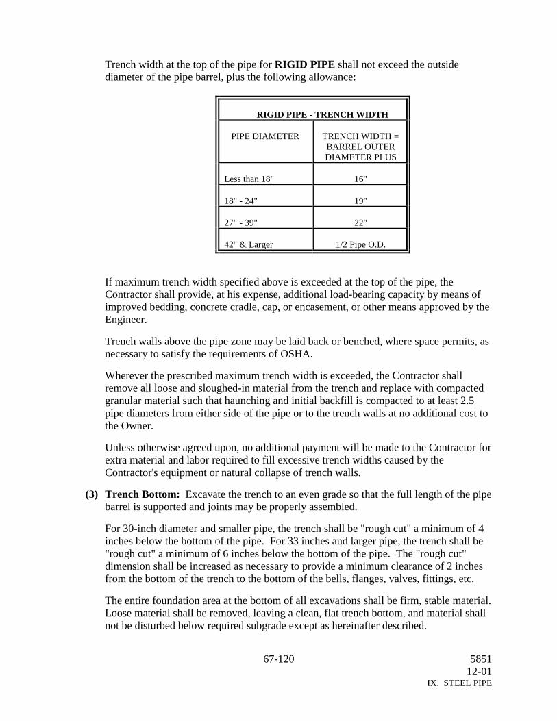
67-120 585112-01
IX. STEEL PIPE
Trench width at the top of the pipe for RIGID PIPE shall not exceed the outsidediameter of the pipe barrel, plus the following allowance:
RIGID PIPE - TRENCH WIDTH
PIPE DIAMETER TRENCH WIDTH =BARREL OUTERDIAMETER PLUS
Less than 18" 16"
18" - 24" 19"
27" - 39" 22"
42" & Larger 1/2 Pipe O.D.
If maximum trench width specified above is exceeded at the top of the pipe, theContractor shall provide, at his expense, additional load-bearing capacity by means ofimproved bedding, concrete cradle, cap, or encasement, or other means approved by theEngineer.
Trench walls above the pipe zone may be laid back or benched, where space permits, asnecessary to satisfy the requirements of OSHA.
Wherever the prescribed maximum trench width is exceeded, the Contractor shallremove all loose and sloughed-in material from the trench and replace with compactedgranular material such that haunching and initial backfill is compacted to at least 2.5pipe diameters from either side of the pipe or to the trench walls at no additional cost tothe Owner.
Unless otherwise agreed upon, no additional payment will be made to the Contractor forextra material and labor required to fill excessive trench widths caused by theContractor's equipment or natural collapse of trench walls.
(3) Trench Bottom: Excavate the trench to an even grade so that the full length of the pipebarrel is supported and joints may be properly assembled.
For 30-inch diameter and smaller pipe, the trench shall be "rough cut" a minimum of 4inches below the bottom of the pipe. For 33 inches and larger pipe, the trench shall be"rough cut" a minimum of 6 inches below the bottom of the pipe. The "rough cut"dimension shall be increased as necessary to provide a minimum clearance of 2 inchesfrom the bottom of the trench to the bottom of the bells, flanges, valves, fittings, etc.
The entire foundation area at the bottom of all excavations shall be firm, stable material.Loose material shall be removed, leaving a clean, flat trench bottom, and material shallnot be disturbed below required subgrade except as hereinafter described.

68-120 585112-01
IX. STEEL PIPE
If the subgrade is soft, spongy, disintegrated, or where the character of the foundationmaterials is such that a proper foundation cannot be achieved at the elevation specified,the Contractor shall deepen the excavation, not less than 6-inches to a depth where asatisfactory foundation may be obtained. The subgrade shall then be brought back tothe required grade with Class I coarse gravel compacted to seventy percent (70%)relative density per ASTM D-4254.
(4) Over Excavation: If the trench is excavated to a faulty grade (at a lower elevation thanindicated), correct the faulty grade at no additional cost to the Owner, as specifiedbelow:
(a) In uniform, stable dry soils, correct the faulty grade with Class II granularembedment material thoroughly compacted to ninety percent (90%) ModifiedProctor Density per ASTM D-1557.
(b) In soft spongy disintegrated soils, or where necessary to allow proper drainage,correct the faulty grade with Class I coarse gravel compacted to seventy percent(70%) of relative density.
(5) Rock Excavation: When pipe is to be laid in rock cut, provide a clearance of at least 6inches below parts of the pipe, valves, or fittings. Provide adequate clearance at bellholes to permit proper jointing of pipe laid in rock trenches. Refill excavation to pipegrade with Class II granular embedment material compacted to ninety percent (90%)Modified Proctor Density. Unless specifically required and called for in thespecifications, and with a permit issued by governing authorities, blasting shall not bepermitted.
(6) Bell Holes: Bell holes of ample dimension shall be dug in trenches at each joint of pipeto permit the jointing to be made properly, visually inspected, and so that the pipe willrest on the full length of the barrel.
Trench Width: Trench width shall be as specified for RIGID pipe in Section 13,Item (2).
Embedment: Unless otherwise specified or shown on the drawings, Steel Pipe shall beembedded in material as defined in Section 12, Item (4). If NATIVE material is notsuitable, CLASS II material as defined in Section 12, Item (4) shall be used.
General: Just before each joint is lowered into the ditch, it is to be inspected and thecoating "jeeped" for holidays. All holidays are to be repaired before the pipe is loweredinto the trench. All pipe, fittings, etc., shall be carefully handled and protected againstdamage to lining and coating, interior and exterior surfaces, impact shocks and free fall.In loading and unloading, material shall be lifted by hoists or rolled on skidways so asto prevent damage. All pipe-handling equipment shall be acceptable to the Engineer.
Pipe Embedment: Unless otherwise specified or shown on the drawings, Steel Pipeshall be embedded in NATIVE material as defined in these specifications. If NATIVEmaterial is not suitable, CLASS II material shall be used.

69-120 585112-01
IX. STEEL PIPE
Installation - Welded Joints: Weld joints in accordance with the AWWA C-206. Weldsshall be full circle fillet welds. If the ends of the pipe are laminated, split, or damagedto the extent that satisfactory welding contact cannot be obtained, remove the pipe fromthe line.
Each welder shall be required to identify his work with a code marking, and listing ofthe names of the welders with corresponding code marks shall be furnished to theEngineer. Any welder making defective welds shall not be allowed to continue to weld.
If the Contractor disagrees with the Engineer's interpretation of welding tests, testsections may be cut from the joint for physical testing. The Contractor shall bear theexpense of repairing the joint, regardless of the results of physical testing. Theprocedure for repairing the joint shall be approved by the Engineer before proceeding.
Adequate provisions for reducing temperature stresses shall be the responsibility of theContractor.
After the pipes have been joined and properly aligned and prior to the start of thewelding procedure, the spigot and bell shall be made essentially concentric byshimming or tacking to obtain clearance tolerance around the periphery of the joint. Inno case shall the clearance tolerance be permitted to accumulate.
Before welding, thoroughly clean pipe ends. Weld pipe by machine or by the manualshielded electric arc process. Welding shall be performed so as not to damage lining orcoating. Cover the tape coating as necessary to protect from welding.
Furnish labor, equipment, tools, and supplies, including shielded type welding rod.Protect welding rod from any deterioration prior to its use. If any portion of a box orcarton is damaged, reject the entire box or carton.
Deposit metal in successive layers so that there will be at least 2 passes or beads in thecompleted welds. Deposit no more than 1/4-inch or metal on each pass. Thoroughlyclean each pass, including the final pass, by wire brushing and hammering to removedirt, slag or flux.
In all hand welding, the metal shall be deposited in successive layers so that there are atleast as many passes or beads in the completed weld as indicated in the following table:
Plate ThicknessInches
Fillet Weld, MinimumNumber of Passes
3/16” 11/4” 2
5/16” 23/8” 3
13/32” 37/16” 3
15/32” 41/2” 4
More than 1/2” 1 for each 1/8 inch and anyremaining fraction thereof

70-120 585112-01
IX. STEEL PIPE
For hand welds, not more than 1/8" of metal shall be deposited in each pass. Each passexcept the final one, whether in butt or fillet welds, shall be thoroughly bobbed orpeened to relieve shrinkage stresses and to remove dirt, slag, or flux before thesucceeding bead is applied. Each pass shall be thoroughly fused into the plates at eachside of the welding groove or fillet and shall not be permitted to pile up in the center ofthe weld. Undercutting along the side shall not be permitted.
Welds shall be free from pin holes, non-metallic inclusions, air pockets, undercuttingand/or any other defects.
Installation - Rubber Gasket Joints: Join rubber gasket joints in accordance with theManufacturer's recommendations. Clean bell and spigot of foreign material. Lubricategaskets and relieve gasket tension around the perimeter of the pipe. Engage spigot asfar as possible in bell, allowing for a 3/8" to 1" gap for inside joint grouting after anyjoint deflection. Contractor shall verify that gaskets have been placed properly andwere not disturbed during installation with manufacturer supplied feeler gauge. Rolledgaskets shall be corrected by removing and reinserting the pipe.
Interior Joint Grouting for Pipe with Plant-Applied Mortar Lining : Upon completionof backfill, fill the inside joint recess with a stiff cement mortar as indicated.
Prior to the placing of mortar, clean out dirt or trash which has collected in the joint,and moisten the mortar surfaces of the joint space by spraying or brushing with a wetbrush. Ram or pack the stiff mortar into the joint space and take extreme care to insurethat no voids remain in the joint space.
After the joint has been filled, level the surface of the joint with the interior surfaces ofthe pipe by steel troweling.
Carefully inspect every joint to insure a smooth continuous interior surface.Thoroughly clean the interior of the pipe and remove any obstructions that may reduceits carrying capacity.
Interior joints of pipe smaller than 21" in diameter shall have the bottom of the bellbuttered with mortar, prior to inserting the spigots, such that when the spigot is pushedinto position it extrudes surplus mortar from the joint. The surplus mortar shall bestruck off flush by pulling a filled burlap bag or inflated ball through the pipe.
Field-Applied Outside Joint Coating: Clean the surface of foreign materials. Removeweld slag, splatter, and scale. Remove by grinding or filing the sharp edges or burrsthat could puncture or cut the tape. Clean the surface using a solvent wash and wirebrushing, dry, and prime the surface prior to tape coating.
Wrap joints with a tape coating system conforming to AWWA C-209, consisting ofthree layers, a primer layer, and two (2) 35 mm tape layers. Overlap the factory-appliedcoating system with the field-applied coating system a minimum of 6 inches and bondtogether.

71-120 585112-01
IX. STEEL PIPE
Protection of Exposed Metal: Exposed ferrous metal such as, bolts and flanges, whichcannot be protected with field-applied tape coatings shall receive a coat of KoppersBitumastic No. 50, or approved equal.
Patch of Coating: When visual inspection shows a portion of the tape system hassustained physical damage, the area in question may be subjected to an electricalholiday test to 6,000 volts.
When the area is tested and there are no holidays or tearing of the material, (onlywrinkling or bruising) no patching is required.
When the damaged area has a tearing of material, remove the damaged layer(s) of outer-wrap by carefully cutting with a sharp razor type utility knife. Wipe the area clean anddry with a rag. Apply the repair tape using a "cigarette wrap" in accordance with thetape manufacturer's recommendation. The repair tape is to overlap at least 6 inches ofsound material.
When the damaged surface shows damage all the way to steel from either a visualinspection or a jeep from a holiday detector, expose the inner-wrap of black tape and cutback the damaged layers leaving a smooth surface. Wipe the area clean and dry with arag. Apply a coat of primer to the area. When the primer is tacky, apply repair tapeusing a "cigarette wrap" in accordance with the tape manufacturer's recommendation ofsufficient size to completely cover the damaged areas, plus a minimum lap of 6 inch onsound tape in all directions. Apply a second patch of repair tape over the first patch.Overlap the first patch a minimum of 6 inches with the second patch.
Patch of Lining: Repair cracks larger than 1/16" and disbanded linings. Excessivepatching of lining shall not be permitted. Field-patching of lining shall be allowedwhere area to be repaired does not exceed 100 square inches and has no dimensiongreater than 12". Repair larger areas by gunite method and reinforce work. The groutused for repair shall be non-metallic and a non-shrink grout. There shall be not morethan one patch in the lining of any joint of pipe.
Wherever necessary to patch the pipe, make the patch with the mortar indicated. Do notinstall patched pipe until the patch has been properly and adequately cured and unlessapproved for installation by the Engineer.
14. Testing: Disinfect and test the piping system in accordance with Section I entitled “WaterMains and Reclaim Water Mains, Sections 4 and 5 of these Specifications and as detailed inAWWA C-651.
Test the field-applied joint coating for holidays after field-applied coating and prior tobackfilling as per AWWA C-209.
72-120 585112-01
IX. STEEL PIPE
Where welds cannot be tested by hydrostatic tests, such as fittings adjacent to test valves,Contractor shall perform a dye penetrant test in accordance with ASTM E-165. Replace orrepair welds, whichever is deemed necessary by Engineer, that prove to be defective at theContractor's expense. The Engineer shall approve all patch work necessary during suchtests.

73-120 585112-01
X. Polyvinyl Chloride (PVC) Pipe
X. Poly Vinyl Chloride (PVC) Pipe
1. General.
(1) Description. This section specifies Poly Vinyl Chloride (PVC) pipe and fittings.
(2) Quality Assurance.
(a) References. This section contains references to the following documents. Theyare a part of this section as specified and modified. In case of conflict between therequirements of this section and those of the listed documents, the requirements ofthis section shall prevail.
Reference TitleANSI/NSF 61 Drinking Water System Components – Health EffectsASTM D1784 Rigid Poly Vinyl Chloride (PVC) Compounds and
Chlorinated Poly Vinyl Chloride (CPVC) CompoundsASTM D1785 Poly Vinyl Chloride (PVC) Plastic Pipe, Schedules 40,
80, and 120ASTM D2241 Specification for Poly Vinyl Chloride (PVC) Pressure-
Rated Pipe (SDR-Series)ASTM D2464 Threaded Poly Vinyl Chloride (PVC) Plastic Pipe
Fittings, Schedule 80ASTM D2466 Poly Vinyl Chloride (PVC) Plastic Pipe Fittings,
Schedule 40ASTM D2467 Socket-Type Poly Vinyl Chloride (PVC) Plastic Pipe
Fittings, Schedule 80ASTM D2564 Solvent Cements for Poly (Vinyl Chloride) (PVC)
Plastic Pipe and FittingsASTM D2774 Recommended Practice for Underground Installation of
Thermoplastic Pressure PipingASTM D3034 Type PSM Poly Vinyl Chloride (PVC) Sewer Pipe and
FittingsASTM F402 Practice for Safe Handling of Solvent Cements and
Primers Used for Joining Thermoplastic Pipe andFittings
ASTM F477 Specifications for Elastomeric Seals (Gaskets) forJoining Plastic Pipe
ASTM F679 Poly Vinyl Chloride (PVC) Large Diameter PlasticGravity Sewer Pipe and Fittings
AWWA C900 Poly Vinyl Chloride (PVC) Pressure Pipe, 4-inchesthrough 12 Inches, for Water Distribution
AWWA C905 Standard for Poly Vinyl Chloride (PVC) WaterTransmission Pipe, Nominal Diameters 14-inchesthrough 36-inches.
AWWA M-23 Manual: PVC Pipe – Design and Installation

74-120 585112-01
X. Polyvinyl Chloride (PVC) Pipe
Reference TitleUNI-BELL-3 Poly Vinyl Chloride (PVC) Pressure Pipe (Complying
with AWWA Standard C-900)UNI-BELL-11 Poly Vinyl Chloride (PVC) Water Transmission Pipe
Nominal Diameters 14-inches through 36-inches
2. Products.
(1) PVC Pipe.
(a) Pressure Pipe. PVC material for pipe and fittings shall conform to ASTM D1784,Class 12454-B. Pipe and fittings shall either be in accordance with AWWA C900or with ASTM 1785 as specified in this specification. Pressure rating for pipe shallbe in excess of test pressure specified in this specification. Neoprene gaskets withpush-on joints shall conform to ASTM F477. Schedule 80 PVC socket type fittingsshall conform to ASTM D2467. Schedule 40 PVC fittings shall conform to ASTMD2466. PVC solvent weld cement for socket connections shall meet therequirements of ASTM D2564. Schedule 80 PVC threaded fittings shall conformto ASTM D2464. Fittings for gasketed pipe shall be ductile iron fittings ratedfor use with the specified Class of PVC pipe.
(b) Non-pressure Pipe.
Gravity Sewer Pipe: PVC material for sewer pipe and fittings shall conform toClass 12454-B, as defined in ASTM D1784. Pipe and fittings shall meet therequirements of ASTM D3034 for SDR 35 and ASTM F679 for large diameterpipe. Neoprene gaskets with push-on joints shall conform to ASTM F477.
(2) Product Data. The following information shall be provided:
Manufacturer's certificates of compliance with the specified standards and Contractor'slayout drawings.
3. Execution.
(1) Installation. PVC pipe 3-inch in diameter and smaller shall be joined by means ofsocket fittings and solvent welding in conformance with ASTM F402. Solvent-cemented joints shall be made in strict compliance with the manufacturer's/supplier'sinstructions and recommended procedures. Unless otherwise specified, PVC pipes 4inch in diameter and greater shall be joined by means of gasketed push-on joints andductile iron push-on or mechanical joint fittings. Unless otherwise specified, PVCpiping exposed to sunlight shall be painted.
Connections to different types of pipe shall be by means of flanges, specified adaptersor transition fittings. Where sleeve type couplings are used, both shall be uniformlytorqued in accordance with pipe manufacturer's recommendation. Foreign materialshall be removed from the pipe interior prior to assembly. Flanged adapters shall beprovided for connection to valves unless otherwise specified.
(2) Testing. Testing of plastic piping shall be as specified in this specification.

75-120 585112-01
XI. Piping Connections
XI. Piping Connections
1. General.
(1) Description. This section specifies the following methods of connecting metallicpiping: flanges, threading, mechanical couplings, dielectric unions, and welding.
(2) References. This section contains references to the following documents. They are apart of this section as specified and modified. In case of conflict between therequirements of this section and the listed documents, the requirements of this sectionshall prevail.
Reference TitleANSI Bl.1-82 Unified Inch Screw Threads (UN and UNR Thread Form)ANSI Bl.20.1-83 Pipe Threads, General Purpose (Inch)ANSI B16.1-89 Cast Iron Pipe Flanges and Flanged Fittings Class 25,
125, 250, and 800ANSI B16.5-88 Pipe Flanges and Flanged FittingsANSI B18.2.1-81 Square and Hex Bolts and Screws Inch Series Including
Hex Cap Screws and Lag ScrewsANSI B18.2.2-87 Square and Hex NutsANSI B31.1-89 Power PipingANSI B31.3-87 Chemical Plant and Petroleum Refinery PipingASME Section IX(1989)
Boiler and Pressure Vessel Code; Welding and BrazingQualifications
ASTM F37-88 Standard Test Methods for Sealability of GasketMaterials
ASTM F104-88 Standard Classification System for Nonmetallic GasketMaterials
ASTM F152-87 Standard Test Methods for Tension Testing ofNonmetallic Gasket Materials
AWWA C111-85 Rubber-Gasket Joints for Ductile-Iron and Gray-IronPressure Pipe and Fittings
AWWA C206-88 Field Welding of Steel Water PipeAWWA C207-86 Steel Pipe Flanges for Waterworks Service--Size 4-inch
through 144-inch.AWWA C606-87 Grooved and Shouldered Type JointsAWWA Mll-85 Steel Pipe--A Guide for Design and Installation
2. Products.
(1) Flange Assemblies.
(a) Flanges. Cast iron flanges shall be faced in accordance with ANSI B16.1. Wherecompanion flanges are used, the flanges on pipe shall be refaced to be flush withthe companion flange face. Class 150 and Class 300 forged steel flanges shall beraised faces conforming to ANSI B16.5. Lightweight slip-on flanges shall be plain

76-120 585112-01
XI. Piping Connections
face conforming to AWWA C207, Class B and ANSI B16.5. Unless otherwisespecified, steel flanges shall be ANSI B16.5, Class 150 or AWWA C207, Class D.Class E AWWA flanges shall be provided where test pressure exceeds 175 psi.Plain-faced flanges shall not be bolted to raised face flanges.
(b) Gaskets. Gasket material shall be as specified in paragraph 2.(3), “Gaskets” forplain-faced flanges shall be the full-face type. Thickness shall be 1/16-inch forpipe 10 inches and less in diameter and 1/8-inch for pipe 12 inches and larger indiameter. Unless otherwise specified, gaskets for raised face flanges shall matchthe raised face and shall be 1/16-inch thick for pipe 3-1/2 inches and less indiameter and 1/8-inch thick for pipe 4 inches and larger.
(c) Bolts. Flange assembly bolts shall be ANSI B18.2.1 standard square or hexagonhead carbon steel machine bolts with ANSI B18.2.2 standard hot pressed hexagonnuts. Threads shall be ANSI Bl.1, standard coarse thread series; bolts shall beClass 2A, nuts shall be Class 2B. Bolt length shall conform to ANSI B16.5.Flange assembly bolts and nuts for submerged or buried service shall be made ofnon-corrosive high-strength, low-alloy steel as specified in ANSI/AWWAC111/A21.11, regardless of any other protective coating.
(2) Mechanical Couplings.
(a) Sleeve-type Couplings. Unless otherwise specified, sleeve-type mechanical pipecouplings shall be Rockwell Type 411, Dresser Style 38, or equal, with the stopremoved from the middle ring. Reducing couplings shall be Rockwell Type 415,Dresser Style 62, or equal. Sleeve-type flanged coupling adapters shall beRockwell Type 913, Dresser Style 128, or equal. Insulating couplings shall beRockwell Type 416, Dresser Style 39, or equal. Bolts and nuts shall be made ofhigh-strength, low-alloy steel as specified in ANSI/AWWA C111/A21.11.
Gaskets shall be as specified in paragraph 2.C and AWWA C111.
(b) Plain-End Couplings. Plain end pipe couplings for pipe sizes 6 inches and smallershall be Gustin-Bacon 200, Victaulic Style 99, or equal for Schedule 80 pipe andGustin-Bacon 205, Victaulic Style 90, or equal for lighter weight pipe. Plain endcouplings for pipe size 8 inch and larger shall be Gustin-Bacon 200, Victaulic Style99, or equal. Unless otherwise specified, bolts and nuts shall comply with AWWAC606.
Gaskets shall be as specified in Section 2, Item (3) of these specifications andAWWA C606.
(c) Grooved End Couplings. Grooved end flexible-type couplings shall be Gustin-Bacon 100, Victaulic Style 77, or equal. Grooved end rigid-type couplings shall beGustin-Bacon 120 Rigi-Grip, Victaulic Style 07 Zero-Flex, or equal. Flexible-typecouplings shall be used for all piping greater than 12 inches in diameter. In rack-mounted tunnel piping applications shall be used for pipe 12 inches in diameter andless and for grooved joints adjacent to pump or blower suction and discharge wheregrooved couplings are used for noise and vibration control. All other applicationsfor piping 12 inches in diameter and less shall utilize rigid-type couplings.

77-120 585112-01
XI. Piping Connections
Grooved end flanged coupling adapters shall be either Gustin-Bacon 154, VictaulicStyle 741, or equal. Snap-joint grooved end couplings shall be Gustin-Bacon 115,Victaulic Style 78, or equal. Cut grooves are not permitted on fabricated orlightwall pipe. Unless otherwise specified, bolts and nuts shall comply withAWWA C606. Bolts and nuts for submerged or buried service shall be high-strength, low-alloy steel as specified in ANSI/AWWA C111/A21.11.
Gaskets shall be as specified in Section 2, Item (3) of these specifications andAWWA C 606.
(3) Gaskets. Gaskets designated in this specification shall be as follows:
(a) EPDM. ethylene-propylene-diene-terpolymer
(b) Neoprene. Neoprene
(c) Nitrile. nitrile (Buna N)
(d) Compressed gasketing consisting of organic fibers (Kevlar) and neoprene binder;ASTM F104 (F712400), 2500 psi (ASTM F152), 0.2 ML/HR LEAKAGE Fuel A(ASTM F37)
(e) Compressed gasketing consisting of organic fibers (Kevlar) and SBR binder;ASTM F104 (F712400), 2500 PSI (ASTM F152), 0.1 ml/hr leakage Fuel A (ASTMF37)
(f) Gylon gasketing, Garlock Style 3500, 2000 psi (ASTM F152), 0.22 ml/hr Fuel A(ASTM F37)
(g) Gylon gasketing, Garlock Style 3510, 2000 psi (ASTM F152), 0.04 ml/hr Fuel A(ASTM F37)
(h) Gylon gasketing, Garlock Style 3504, 2000 psi (ASTM F152), 0.12 ml/hr Fuel A(ASTM F37)
(i) TFE. noncreeping tetrafluoroethylene (TFE) with insert filler
(j) TFE bonded EPDM. TFE bonded to EPDM in full-face gasket having concentric-convex molded rings
(4) Thread. Pipe thread dimensions and size limits shall conform to ANSI Bl.20.1.
(5) Dielectric Unions. Dielectric unions shall be EPCO, Capital, or equal.
(6) Coatings. Unless otherwise specified, flange assemblies and mechanical typecouplings for buried installation shall be field coated with System M-1 as specified inthis specification.
(7) Product Data. In accordance with this specification, the Contractor shall provide foreach welder, a welder qualification certificate indicating the welder is certified for pipewelding in accordance with ASME Boiler and Pressure Vessel, Section IX. Each

78-120 585112-01
XI. Piping Connections
welder's certificate shall be provided to the Construction Manager prior to that welderworking on the job.
3. Execution.
(1) Pipe Cutting, Threading, and Jointing. Pipe cutting, threading, and jointing shallconform to the requirements of ANSI B31.1.
(2) Pipe Welding. Pipe shall be welded by ASME-certified welders using shielded metalarc, gas shielded arc or submerged arc welding methods. Welds shall be made inaccordance with the requirements of ANSI B31.1 for piping Systems 8, 26, and 28specified in this specification. Welds shall be made in accordance with therequirements of ANSI B31.3 for piping system 1 (oxygen high pressure) specified inthis specification.
Welds for piping systems not specified above shall be made in accordance with AWWAC206.
(3) Takedown Couplings. Takedown couplings shall be screw unions, flanged or groovedend mechanical coupling type joints and shall be provided as specified. Flanged orgrooved end joints shall be employed on pipelines 2-1/2 inches in diameter and larger.Where piping passes through walls, takedown couplings shall be provided within 3 feetof the wall, unless specified otherwise.
A union or flanged connection shall be provided within 2 feet of each threaded endvalve.
(4) Flexibility. Unless otherwise specified, piping 2 inches in diameter and larger passingfrom concrete to earth shall be provided with two pipe couplings or flexible joints asspecified within 2 feet or one pipe diameter of the structure, whichever is greater.Where required for resistance to pressure, mechanical couplings shall be restrained inaccordance with AWWA M-11, paragraph 13.10, Tables 13-6 and 13-7, and Figure13-17.
(5) Dielectric Connections. Where a copper pipe is connected to steel or cast iron pipe, aninsulating section of rubber or plastic pipe shall be provided. The insulating sectionshall have a minimum length of 12 pipe diameters. Dielectric unions as specified inparagraph 2.E may be used instead of the specified insulating sections. Where copperpipe is supported from hangers, it shall be insulated from the hangers, or copper-platedhangers shall be used.
79-120 585112-01
XII. Gate Valves
XII. Gate Valves
1. Description. This section specifies bronze and iron-body, solid-wedge gate valves. Ironbody valves shall be bronze mounted. The Contractor shall furnish all valves whereindicated on the plans, as called for in these Specifications, or as required for properoperation of the equipment in general. Unless otherwise indicated on the plans or specifiedin other sections of these Specifications, valves shall conform to the requirements asspecified herein.
2. Quality Assurance.
References. This section contains references to the following documents. They are apart of this section as specified and modified. In case of conflict between therequirements of this section and those of the listed documents, the requirements of thissection shall prevail.
Reference Title
ANSI B16.1-89 Cast Iron Pipe Flanges and Flanged Fittings Class 25,125, 250 and 800
ASTM A126-84 Gray Iron Castings for Valves, Flanges, and PipeFittings
AWWA C-105 Polyethylene Encasement for Ductile-Iron PipeSystems
AWWA C500-86 Gate Valves for Water and Sewer SystemsAWWA C550 Protective Epoxy Interior Coatings for Valves and
HydrantsANSI/NSFStandard 61
“Drinking Water System Components – Health Effects”
Design Criteria. Gate valves 3 inch through 48 inch in size shall comply with AWWAC500, including applicable hydrostatic testing. Gate valves smaller than 3 inches shallbe subject to hydrostatic tests at the test pressure.
3. Products. Valves shall conform to the American National Standards Institute / NationalSanitation Foundation and be certified by an organization accredited by ANSI. Suchcompliance shall be evidenced by an affidavit from the manufacturer or vendor. If the pipedoes not presently conform to this standard, information from the manufacturer regardingaction being taken to comply with this standard must be submitted.
(1) Non-rising Stem Double Disc Gate Valves. Non-Rising Stem Gate Valves are to beiron-body, bronze mounted, parallel seat internal wedging type with non-rising stemand designed for a working pressure of 200 psig. NRS gate valves shall comply withAWWA C-500 "Gate Valves for Water and Sewage Systems", latest revision.
Valves 12-inches or smaller shall be for horizontal installation. The number of turns toopen shall be a minimum of three times the valve diameter.
80-120 585112-01
XII. Gate Valves
Acceptable manufacturers and models shall be:
American-Darling
52NRS (Flanged Ends), 55NRS (MechanicalJoint Ends)
Clow F5065 (Mechanical Joint Ends), F5070(Flanged Ends)
Kennedy 561X (Flanged Ends), 571X (Mechanical JointEnds)
M&H Style 67NRSMueller A-2380-6 (Flanged), A-2380-20 (Mechanical
Joint Ends)
Markings. Shall be cast on the bonnet or body of each valve. Markings shall includethe manufacturer's name or mark, the year the valve casting was made, the size of thevalves, and the designated working pressure.
Valve Ends. Valve ends shall be mechanical joint or flanged with drilling incompliance with ANSI B16.1. Valve ends and size as specified.
Valve Body and Bonnet. Shall be cast iron conforming to ASTM A-126 Class B, orductile iron conforming to ASTM A-395 or ASTM A-536.
Gate. Shall be cast iron or Grade A bronze. Gate rings, constructed of Grade Abronze, shall be rolled, peened, or pressed into grooves machined in the discs, or maybe fastened by some other accepted method.
Body-Seat Ring. Shall be constructed of Grade A bronze, and shall be back-facedthreaded and machined screwed into the valve body.
Wedges. Double-disc gate valves shall be equipped with a free and positive-operatinginternal device which will press the disc seats firmly against the body seats when thevalve is closed and release the load before the discs begin to move when the valve isopened. Wedges shall be simple and rugged in design. The wedge material shall be asspecified in AWWA C-500 and contact surface shall not be iron to iron.
Valve Stem. Shall be constructed of low zinc bronze CDA Copper Alloy No. C99500with a minimum yield strength of 40,000 psi and minimum elongation in 2 inches of10%.
Stem Seals. Shall consist of two O-rings such that the seal above the stem collar can bereplaced with the valve under pressure in the fully open position. O-rings shall meet therequirements of ASTM D-2000 and have physical properties suitable for theapplication.

81-120 585112-01
XII. Gate Valves
Valve Operator. Shall be a cast iron, ASTM A-126 Class B, wrench nut. The nutshall have a 2" square base and shall be 1-15/16" square at the top and be 1-3/4" highand shall open counterclockwise (left). The wrench nut shall be painted black and anarrow indicating direction of opening shall be cast on the nut, according to AWWA C-509.
Protective Coating. An epoxy coating shall be applied to all exterior and all stationaryinterior ferrous surfaces including all interior openings in the valves body. The coatingshall not be applied to the gasket surfaces of the end flanges.
The coating shall be applied in accordance with AWWA C-550 and the manufacturer'sinstructions. After the coating is completely cured, the coated surface shall be tested forporosity, holidays, and pinholes using a holiday detector. All holidays or irregularitiesshall be repaired and the coating again tested.
(2) Outside Screw and Yoke (OS&Y) Gate Valves. Outside Screw and Yoke GateValves are to be iron-body, bronze mounted, parallel seat internal wedging type withoutside screw and yoke and shall comply with AWWA C-500 "Gate Valves for Waterand Sewage Systems". OS&Y Gate Valves shall be provided for the size specified.
Acceptable manufacturers and models shall be:
American Darling 52 OS&YKennedy 566M&H STYLE 68Mueller A-2483-6Clow F5072
Submittals. Submittals shall be provided in accordance with TxDOTs Contractrequirements. Also, the manufacturer shall provide an Affidavit of Compliance inaccordance with Section 1.4, AWWA Standard C-500. Records of all tests performedin accordance with Section 2.2 and Section 5.1, AWWA Standard C-500 shall beprovided. These records will be representative test results for Section 2.2 and certificateof testing for Section 5.1. An affidavit of testing for the valve assembly as outlined inSection 3.1, AWWA Standard C-500 (300 ft-lbs) shall also be provided.
Markings. Shall be cast on the bonnet or body of each valve. Markings shall includethe manufacture's name or mark, the year the valve casting was made, the size of thevalves, and the designated working pressure.
Valve Ends. Valve ends shall be flanged, with drilling in compliance with ANSIB16.1, or as otherwise specified.
Valve Body and Bonnet. Shall be cast iron conforming to ASTM A-126 Class B, orductile iron conforming to ASTM A-395 or ASTM A-536.

82-120 585112-01
XII. Gate Valves
Gate. Shall be cast iron or Grade A bronze. Gate rings, constructed of Grade Abronze, shall be rolled, peened, or pressed into grooves machined in the discs, or maybe fastened by some other accepted method.
Body-Seat Ring. Shall be constructed of Grade A bronze, and shall be back-facedthreaded and machined screwed into the valve body.
Wedges. Double-disc gate valves shall be equipped with a free and positive-operatinginternal device which will press the disc seats firmly against the body seats when thevalve is closed and release the load before the discs begin to move when the valve isopened. Wedges shall be simple and rugged in design. The wedge material shall be asspecified in AWWA C-500 and contact surface shall not be iron to iron.
Valve Stem. Shall be constructed of low zinc bronze CDA Copper Alloy No. C99500with a minimum yield strength of 40,000 psi and minimum elongation in 2 inches of10%. The opening through the bonnet for the stem shall be bushed with Grade A, B, C,D or E bronze as defined in AWWA C-500.
Yoke. The yoke may be either integral or bolted on to bonnet. The design shall be suchthat a hand may not be jammed between the yoke and handwheel.
Valve Operator. Shall be a cast iron, ASTM A-126 Class B, wrench nut. The nutshall have a 2" square base and shall be 1-15/16" square at the top and be 1-3/4" highand shall open counterclockwise (left). The wrench nut shall be painted black and anarrow indicating direction of opening shall be cast on the nut, according to AWWA C-509.
Protective Coating. An epoxy coating shall be applied to all exterior and all stationaryinterior ferrous surfaces including all interior openings in the valves body. The coatingshall not be applied to the gasket surfaces of the end flanges.
The coating shall be applied in accordance with AWWA C-550 and the manufacturer'sinstructions. After the coating is completely cured, the coated surface shall be tested forporosity, holidays, and pinholes using a holiday detector. All holidays or irregularitiesshall be repaired and the coating again tested.
(3) Tapping Valves. Tapping Valves are to be iron-body, bronze mounted, parallel seatinternal wedging type with non-rising stem. Tapping Valves shall conform to AWWAC-500 "Gate Valves for Water and Sewage Systems" except that tapping valves shallhave over-sized seat rings to accommodate full size cutters. Tapping Valves shall beprovided for the size specified.
83-120 585112-01
XII. Gate Valves
Acceptable manufacturers and models shall be:
American Darling 565Kennedy 950-XM&H STYLE 751Mueller H-667Clow 5093
The number of turns to open shall be a minimum of three times the valve diameter.
Submittals. Submittals shall be provided in accordance with TxDOTs Contractrequirements. Also, the manufacturer shall provide an Affidavit of Compliance inaccordance with Section 1.4, AWWA Standard C-500. Records of all tests performedin accordance with Section 2.2 and Section 5.1, AWWA Standard C-500 shall beprovided. These records will be representative test results for Section 2.2 and certificateof testing for Section 5.1. An affidavit of testing for the valve assembly as outlined inSection 3.1, AWWA Standard C-500 (300 ft-lbs) shall also be provided.
Markings. Shall be cast on the bonnet or body of each valve. Markings shall includethe manufacture's name or mark, the year the valve casting was made, the size of thevalves, and the designated working pressure.
Valve Ends. Outlet end of the valve shall be mechanical joint or as otherwisespecified.
Valve Body and Bonnet. Shall be cast iron conforming to ASTM A-126 Class B, orductile iron conforming to ASTM A-395 or ASTM A-536.
Gate. Shall be cast iron or Grade A bronze. Gate rings, constructed of Grade Abronze, shall be rolled, peened, or pressed into grooves machined in the discs, or maybe fastened by some other accepted method.
Body-Seat Ring. Shall be constructed of Grade A bronze, and shall be back-facedthreaded and machined screwed into the valve body.
Wedges. Double-disc gate valves shall be equipped with a free and positive-operatinginternal device which will press the disc seats firmly against the body seats when thevalve is closed and release the load before the discs begin to move when the valve isopened. Wedges shall be simple and rugged in design. The wedge material shall be asspecified in AWWA C-500 and contact surface shall not be iron to iron.
Valve Stem. Shall be constructed of low zinc bronze CDA Copper Alloy No. C99500with a minimum yield strength of 40,000 psi and minimum elongation in 2 inches of10%.
84-120 585112-01
XII. Gate Valves
Stem Seals. Shall consist of two O-rings such that the seal above the stem collar can bereplaced with the valve under pressure in the fully open position. O-rings shall meet therequirements of ASTM D-2000 and have physical properties suitable for theapplication.
Valve Operator. Shall be a cast iron, ASTM A-126 Class B, wrench nut. The nutshall have a 2" square base and shall be 1-15/16" square at the top and be 1-3/4" highand shall open counterclockwise (left). The wrench nut shall be painted black and anarrow indicating direction of opening shall be cast on the nut, according to AWWA C-509.
Protective Coating. An epoxy coating shall be applied to all exterior and all stationaryinterior ferrous surfaces including all interior openings in the valves body. The coatingshall be applied in accordance with AWWA C-550 and the manufacturer's instructions.After the coating is completely cured, the coated surface shall be tested for porosity,holidays, and pinholes using a holiday detector. All holidays or irregularities shall berepaired and the coating again tested.
(4) Non-Rising Stem (NRS) Resilient-Seated Gate Valves. Non-Rising Stem GateValves are to be resilient seat, non-rising stem and shall have a minimum rated workingpressure of 200 psig and shall comply with AWWA C-509 "Resilient-Seated GateValves for Water and Sewage Systems" and AWWA C-550 "Standard for ProtectiveCoatings for Valves and Hydrants". The valves design shall not have any recesses,insets in the bottom of the waterway which would promote build-up or collection ofresidue and debris. Resilient Seated Gate Valves shall be provided for the sizespecified.
With the valve open, the valve shall provide an unobstructed waterway that has adiameter not less than the full nominal diameter of the valve. The minimum number ofturns to open the valve shall be three times the valve diameter.
Acceptable manufacturers and models shall be:
American FlowControl
Series 500, Series 2500
Clow F-6100, F-6102Kennedy Ken-Seal IIM&H 3067US Pipe METROSEAL 250
Submittals. Submittals shall be provided in accordance with TxDOTs Contractrequirements. Also, the manufacturer shall provide approved certified test data or anaffidavit stating that the valve complies with AWWA C-509, Section 6.1 and thefollowing, in accordance with Section 6.2:
Hydrostatic Test. The manufacturer shall pressure test one valve of each size andClass with 400 psi applied to one side and zero to the other. The test shall be madein each direction across the closed gate.

85-120 585112-01
XII. Gate Valves
Torque Test. The manufacturer shall over-torque a valve of each size todemonstrate that no distortion of the valve stem occurs. The applied torque shall be250 ft-lb for a 4" valve and 350 ft-lb for the larger valves in both the open andclosed position.
Leakage Test. The manufacturer shall select two valves of each size to be fullyopened and closed for 500 complete cycles with a 200 psi differential pressureacross the gate. The valve shall be drip tight upon completion of the test.
Pressure Test. One valve of each size shall be tested, with the gate fully open, to apressure of 500 psi. There shall be no evidence of rupture or cracking of valvebody, bonnet or seal plated.
Markings. Shall be cast on the bonnet or body of each valve. Markings shall includethe manufacture's name or mark, the year the valve casting was made, the size of thevalves, and the designated working pressure.
Valve Ends. Shall be mechanical joint or flanged ends as specified.
Valve Body and Bonnet. Shall be cast iron conforming to ASTM A-126, or ductileiron conforming to ASTM A-536 or A-395.
Bolts. All bonnet and seal plate bolts shall be factory installed and made from stainlesssteel ASTM A-276 with either regular square or hexagonal heads with dimensionsconforming to ANSI B18.2.1.
Wedge. The wedge shall be cast iron or ductile iron fully encapsulated with resilientrubber material bonded to the disc. The method for bonding the resilient material shallbe confirmed by ASTM D-429 as required by AWWA C-509.
Valve Stem. Shall be constructed of low zinc bronze CDA Copper Alloy No. C99500with a minimum yield strength of 40,000 psi and minimum elongation in 2 inches of10%.
Stem Seals. Shall consist of two O-rings such that the seal above the stem collar can bereplaced with the valve under pressure in the fully open position. O-rings shall meet therequirements of ASTM D-2000 and have physical properties suitable for theapplication.
Valve Operator. Shall be a cast iron, ASTM A-126 Class B, wrench nut. The nutshall have a 2" square base and shall be 1-15/16" square at the top and be 1-3/4" highand shall open counterclockwise (left). The wrench nut shall be painted black and anarrow indicating direction of opening shall be cast on the nut, according to AWWA C-509.
Protective Coating. An epoxy coating shall be applied to all exterior and all stationaryinterior ferrous surfaces including all interior openings in the valves body. The coatingshall not be applied to the gasket surfaces of the end flanges.
The coating shall be applied in accordance with AWWA C-550 and the manufacturer'sinstructions. The epoxy coating shall have a minimum dry film thickness of 8 mils.

86-120 585112-01
XII. Gate Valves
After the coating is completely cured, the coated surface shall be tested for porosity,holidays, and pinholes using a holiday detector. All holidays or irregularities shall berepaired and the coating again tested.
(5) Materials. Materials of construction shall be as follows:
Component MaterialBody:
3 inches and smaller BronzeLarger than 3 inches Cast iron, ASTM A126, Class B
Wedge:3 inches and smaller BronzeLarger than 3 inches Cast iron, ASTM A126, Class B
Mounting: BronzeStem: Bronze, AWWA C500, Section 3.12
Seat rings:Bronze, Grade A, AWWA C500,Section 3.8
(6) Manufacture.
(a) General. Unless otherwise specified, bronze gate valves shall be provided withintegral seats.
Iron body valves shall be provided with screwed-on seat rings. Exposed gatevalves shall be rising stem type. Buried or submerged gate valves shall be of thenon-rising stem type. Rising stem valves and brass non-rising stem valves shall beprovided with Teflon braid packing. Iron body non-rising stem valves shall beprovided with O-ring stem seals.
(b) End Connections. Gate valve end connections shall be flanged or threaded asspecified. Threaded ends shall not be provided on gate valves with endconnections larger than 4 inches. End flanges shall be integral with the gate valvebody and be faced and drilled in accordance with ANSI B16.1 for 125 lb flanges.
(c) Manual Operators. Unless specified otherwise, valves less than 12 inch size shallbe provided with hand-wheels, and valves 12 inch and larger shall be provided withgeared operators.
(d) Bypass. Unless otherwise specified, gate valves, 16 inch and larger, shall beprovided with a bypass valve sized in accordance with AWWA C500.

87-120 585112-01
XII. Gate Valves
(7) Product Data. The following information shall be provided:
(a) Complete shop drawings and specifications shall be furnished for approval prior toinstallation and acceptance of system. The manufacturer shall provide an Affidavitof Compliance in accordance with Section 1.4, AWWA Standard C-500. Recordsof all tests performed in accordance with Section 2.2 and Section 5.1, AWWAStandard C-500 shall be provided. If requested, the valve manufacturer shall alsosubmit a list of similar installations that have been in satisfactory operation for atleast three years.
An affidavit of testing for the valve assembly as outlined in Section 3.1, AWWAStandard C-500 (300 ft-lbs) shall also be provided.
(b) The manufacturer shall furnish two complete sets of installation, operation, andmaintenance instructions for each type of valve furnished. Instructions shall bebound in a cover.
(c) An affidavit of testing for the valve assembly as outlined in Section 3.1, AWWAStandard C-500 (406.75 Joules (300 ft-lbs.)) shall also be provided.
(d) Hydrostatic test results.
4. Execution.
The Contractor shall carefully handle and install valves horizontally in such a manner as toprevent damage to any part of the valves. Installation shall be in accordance withmanufacturer’s instruction. Valves delivered closed to the site shall be opened by theContractor prior to installation. The Contractor shall record the number of turns required toopen the valve. This information shall be submitted to the Utility on the standard valvereport. Gate valves shall be installed in the closed position.
Valves shall be polyethylene-wrapped in accordance with AWWA C-105, unless otherwisespecified. Thrust blocking shall be provided as specified in Items “Piping Systems” and“Plastic Pipe” of these Special Specifications.
5. Testing.
Upon completion of installation of the valves, an acceptance test shall be conducted to verifythe satisfactory operation of the valves. The unit shall be checked for operation and leakage.The valves must perform in a manner acceptable to the Engineer before the Owner issuesfinal acceptance.
6. Measurement.
Gate valves, of each type and size specified, will be measured by each complete installation.Thrust blocks, fittings, couplings and polyethylene wrapping will not be measured forpayment and shall be considered subsidiary to this Item under the respective valve sizes.

88-120 585112-01
XII. Gate Valves
7. Payment.
Gate valves, of each type and size specified, will be paid for at the bid unit price per eachcompletely installed unit.
Additional gate valves requested by the Engineer and not shown on the plans will bemeasured and paid for at the bid unit price per each completely installed unit.

89-120 585112-01
XIII. BUTTERFLY VALVES
XIII. BUTTERFLY VALVES
1. Butterfly Valves. Shall be of the tight-closing, rubber-seated type for Class 150B service.Butterfly valves shall comply with the requirements of AWWA C-504, "Standard forRubber-Seated Butterfly Valves". Butterfly valves shall be provided for the size specified.
Acceptable manufacturers and models shall be:
American-Darling Class 150B Flanged or Mechanical Joint
M&H 450, 4500, 1450
Kennedy 30A, 30C
Mueller Lineseal III
Pratt Groundhog Flanged or Mechanical
Submittals: Submittals shall be provided in accordance with TxDOTs Contractrequirements. Also, the Manufacturer shall provide approved certified test data or anaffidavit stating that the valve complies with the performance tests, leakage tests, hydrostatictest and proof-of-design tests as described in Section 5.2 of AWWA C-504.
Valve Ends: Shall be short body flanged, mechanical joint or as otherwise specified.
Valve Bodies shall be constructed of cast iron ASTM A-126, Class B, or ASTM A-48, Class40 or Ductile Iron, ASTM A-536, Grade 65/45/12.
Valve Discs shall be cast iron conforming to ASTM A-126, Class B or Ductile Ironconforming to ASTM A-536, Grade 65/45/12. Valve disc shall seat in a position of 90degrees to the pipe axis and shall rotate 90 degrees between full open and tight closedposition. Dimensions of clearance for valve discs are required.
Valve Shafts, keys, dowel pins, or taper pins used for attaching valve shaft to the valve discshall be Type 304 or 316 Stainless Steel, conforming to ASTM A-276, or equivalentcorrosion resistant material. All portions of shaft bearings shall be stainless steel or bronze.
Valve shafts may consist of a one-piece unit extending completely through the valve disc, ormay be of the "stub shaft" type as defined in AWWA C-504.
Butterfly valves shall be provided with an extended bonnet, unless otherwise specified.
Shaft Seals shall be a Split-V or O-ring type. Replacement shall be possible withoutremoving the valve shaft.
Valve Seats shall be new natural or synthetic rubber resilient seats to provide tight shut offat the specified pressure. Seats shall be attached to either the disc or the body. Seats shallbe clamped, mechanically secured, bonded, or vulcanized to either the disc or body. Seatrings shall be stainless steel and fastened by stainless steel cap screws.

90-120 585112-01
XIII. BUTTERFLY VALVES
Mating Seat Surface shall be ASTM A-276, stainless steel 18-8, Type 304, or have a 95%pure nickel overlay.
Valve Bearings shall be sleeve type. Bearings shall be manufactured from corrosionresistant, and "self lubricated" materials that will not damage natural or synthetic rubber.
Valve Operators shall be manual with a 50mm (2-inch) square operating nut and turn left(counterclockwise) to open. Operators shall have all gearing totally enclosed and shall bepre-lubricated or grease packed. Operators shall be of the worm gear or traveling nut andlink type with field adjustable stops capable of withstanding 300 ft. lbs. input torque, asrequired by AWWA C-504.
Protective Coating: Except as otherwise specified, all interior steel or cast iron surfacesshall be shop coated in accordance with the requirements of AWWA Standard C-504. Allexternal surfaces for buried valves shall be shop coated with two coats of asphalt varnishaccording to AWWA C-504.
When specified, a standard epoxy interior coating shall be applied in accordance withAWWA Standard C-550, "Standard for Protective Interior Coatings for Valves andHydrants".
Acceptable manufacturers and models shall be:
American-Darling Class 150B Flanged or Mechanical Joint
M&H 450, 4500, 1450
Kennedy 30A, 30C
Mueller Lineseal III
Pratt Groundhog Flanged or Mechanical
Submittals: Submittals shall be provided in accordance with TxDOTs Contractrequirements. Also, the Manufacturer shall provide approved certified test data or anaffidavit stating that the valve complies with the performance tests, leakage tests, hydrostatictest and proof-of-design tests as described in SECTION 5.2 of AWWA C-504.
Valve Ends: Shall be short body flanged, mechanical joint or as otherwise specified.
Valve Bodies shall be constructed of cast iron ASTM A-126, Class B, or ASTM A-48, Class40 or Ductile Iron, ASTM A-536, Grade 65/45/12.
Valve Discs shall be cast iron conforming to ASTM A-126, Class B or Ductile Ironconforming to ASTM A-536, Grade 65/45/12. Valve disc shall seat in a position of 90degrees to the pipe axis and shall rotate 90 degrees between full open and tight closedposition. Dimensions of clearance for valve discs are required.

91-120 585112-01
XIII. BUTTERFLY VALVES
Valve Shafts, keys, dowel pins, or taper pins used for attaching valve shaft to the valve discshall be Type 304 or 316 Stainless Steel, conforming to ASTM A-276, or equivalentcorrosion resistant material. All portions of shaft bearings shall be stainless steel or bronze.
Valve shafts may consist of a one-piece unit extending completely through the valve disc, ormay be of the "stub shaft" type as defined in AWWA C-504.
Butterfly valves shall be provided with an extended bonnet, unless otherwise specified.
Shaft Seals shall be a Split-V or O-ring type. Replacement shall be possible withoutremoving the valve shaft.
Valve Seats shall be new natural or synthetic rubber resilient seats to provide tight shut offat the specified pressure. Seats shall be attached to either the disc or the body. Seats shallbe clamped, mechanically secured, bonded, or vulcanized to either the disc or body. Seatrings shall be stainless steel and fastened by stainless steel cap screws.
Mating Seat Surface shall be ASTM A-276, stainless steel 18-8, Type 304, or have a 95%pure nickel overlay.
Valve Bearings shall be sleeve type. Bearings shall be manufactured from corrosionresistant, and "self lubricated" materials that will not damage natural or synthetic rubber.
Valve Operators shall be manual with a 50mm (2-inch) square operating nut and turn left(counterclockwise) to open. Operators shall have all gearing totally enclosed and shall bepre-lubricated or grease packed. Operators shall be of the worm gear or traveling nut andlink type with field adjustable stops capable of withstanding 300 ft. lbs. input torque, asrequired by AWWA C-504.
Protective Coating: Except as otherwise specified, all interior steel or cast iron surfacesshall be shop coated in accordance with the requirements of AWWA Standard C-504. Allexternal surfaces for buried valves shall be shop coated with two coats of asphalt varnishaccording to AWWA C-504.
When specified, a standard epoxy interior coating shall be applied in accordance withAWWA Standard C-550, "Standard for Protective Interior Coatings for Valves andHydrants".
2. Air Release, Air/Vacuum, and Combination Air Valves. Air-Release, Air/Vacuum andCombination Air Valves shall comply with AWWA C-512 and the following specifications.These specifications shall apply to valve sizes 150mm (6 inch) and smaller.
Air Release Valves (AR) shall be designed to automatically release accumulated air pocketswithin the pipeline while in operation and under pressure. Air release valves shall be APCOModel 200, Val-Matic Model 38, or Crispin Model P.
Air/Vacuum Valves (AV) shall be designed to allow large volumes of air to escape throughthe valve orifice when filling a pipeline and to close watertight once the air has beenexpelled. Air and vacuum valves shall also permit large volumes of air to enter through thevalve orifice when the pipeline is being drained to break the vacuum. Air and vacuumvalves shall be APCO Series 140, Val-Matic Series 100, or Crispin Model AL.

92-120 585112-01
XIII. BUTTERFLY VALVES
Combination Air Valves (CAV) shall be heavy-duty air and vacuum valves with air release.Combination Air Valves shall be designed to release accumulations of air at high pointswithin a pipeline by exhausting large volumes of air as the pipeline is being filled and byreleasing accumulated pockets of air while the pipeline is in operation and under pressure.Combination air valves shall also be designed to permit large volumes of air to enter thepipeline during pipeline drainage. Combination Air Valves shall be APCO, Val-MaticSeries 200, or Crispin Model C.
Submittals: The manufacturer shall provide an affidavit stating that the valve and allmaterials used in its construction conform to the applicable requirements of AWWA C-512and these specifications. When required, the manufacturer shall provide an affidavit statingthat the valve has been tested and is in compliance with the requirements specified inSection 5.1 of AWWA C-512.
Markings: Manufacturer's name or trademark, size of valve, and the designated maximumworking pressure rating shall be cast in the body or marked on a corrosion-resistant nameplate.
Body and Cover: Each air valve shall have a cast or ductile iron body and cover. Cast ironshall comply with ASTM A-126 Class B, or ASTM A-48 Class 35. Ductile iron shallcomply with the requirements of ASTM A-536, Grade 65-45-12. Bolting material shallmeet or exceed the strength requirements of ASTM A-307. All internal trim shall be ofstainless steel.
Float: Shall be stainless steel. Float shall be baffled to prevent air from blowing valveclosed until air is exhausted. Valve body, float, etc., shall be designed for a workingpressure equal to that of the system in which it is installed. Floats for valves with inlet sizesless than 100mm (4 inch) shall be capable of withstanding a collapse pressure of 1000 psig.For larger inlet sizes, floats shall be capable of withstanding a collapse pressure of 750 psig.
Valve Outlet: Shall be fitted to attach discharge pipe as indicated. Valve inlet shall beN.P.T. for 50mm (2 inch) and smaller valves. Valve inlet shall be ANSI flange for 80mm (3inches) and larger valves. Flange rating shall equal or exceed the maximum workingpressure of the system in which it is installed.
Installation: Air release and air/vacuum valves shall be installed within valve vaults, ormanhole, in accordance with Utility Standard Details 263-1, 263-2, 263-3, 263-4 and plans.
Protective Coatings: Interior surface coatings shall not be required unless otherwisespecified. External surfaces shall be coated with the manufacturer's standard primer.

93-120 585112-01
XIV. Manual Valve Operators and Operator Appurtenances
XIV. Manual Valve Operators and Operator Appurtenances
1. Description. This section specifies manual operators for valves and operator appurtenances.
References. This section contains references to the following document. It is a part of thissection as specified and modified. In case of conflict between the requirements of thissection and those of the listed document, the requirements of this section shall prevail.
Reference Title
AWWA C500-86 Gate Valves 3 inch through 48 inch NPS, for Water andSewage Systems
2. Products.
(1) General. Except as specified in valve specification sections, manual operators shall beas specified herein. Operators shall be mounted on the valve and provided as a unit.Each valve body or operator shall have cast thereon the word "OPEN," an arrowindicating the direction to open, and flow direction arrows.
(2) Operators.
(a) General. Manual operators shall have operating torques less than 80 ft-lbs. Unlessspecified otherwise, the direction of rotation of the operator shall becounterclockwise for opening.
(b) Wrench nuts. Wrench nuts shall comply with Section 3.16 of AWWA C500. Aminimum of two operating keys, but no less than one key per every ten valves,shall be provided for operation of the wrench nut operated valves.
(3) Operator Appurtenances.
(a) Valve Boxes. Valve boxes shall be cast iron and shall have suitable base castingsto fit properly over the bonnets of their respective valves and heavy top sectionswith stay-put covers. Covers shall be hot-dip galvanized.
(b) Floor Boxes. Not used
(c) Adjustable Shaft Valve Boxes. Adjustable shaft valve boxes shall be concrete orcast iron Brooks No. 3RT, Christie G5, Empire 7 valve extension box, or equal.Box covers on water lines shall be impressed with lettering as shown on the plans.
(4) Product Data. Manufacturer’s catalog information and other data-confirmingconformance to design and material requirements shall be provided.
3. Execution.
(1) General. Installation shall be as specified herein. Valve operators shall be located sothat they are readily accessible for operation and maintenance.

94-120 585112-01
XIV. Manual Valve Operators and Operator Appurtenances
(2) Operators.
(a) General. Valves shall be provided with manual operators, unless specifiedotherwise.
(b) Wrench Nuts. Wrench nuts shall be provided on buried valves and wherespecified. Extended wrench nuts shall be provided if necessary so that the nut willbe within 6 inches of the valve box cover.
4. Operator Appurtenances.
(1) Valve Boxes. Valve boxes extending to finished surfaces shall be provided for buriedvalves.
(2) Floor Boxes. Not used.

95-120 585112-01
XV. Fire Hydrants
XV. Fire Hydrants
1. General.
(1) Description.
(a) Scope. This section specifies fire hydrant materials, equipment, and incidentals tofurnish and install fire hydrants as indicated on the drawings, in accordance withUtility requirements and according to typical fire hydrant installation.
(b) Type. Fire hydrants provided under this section shall be two-piece standpipe andstem, compression shutoff, dry-barrel type and shall be designed for a minimumworking pressure of 150 psi and tested at 30 psi hydrostatic pressure.
Hydrant shall have permanent markings identifying name of manufacturer, size ofmain valve opening and year of manufacture. Markings shall be easily located andlegible after the hydrant has been installed.
Hydrants shall be constructed so that the standpipe may be rotated to 8 differentpositions.
Hydrants shall be supplied with extension sections in multiples of 6-inches, withrod and coupling as required, to increase barrel length.
(c) Size. Minimum inside barrel diameter shall be 7 inches. Minimum diameter of themain valve opening shall be 5 inches.
(2) Quality Assurance.
(a) References. This section contains references to the following documents. Theyare a part of this section as specified and modified. In case of conflict between therequirements of this section and those of the listed documents, the requirements ofthis section shall prevail.
Reference TitleAWWA C502-85 Dry-Barrel Fire HydrantsAWWA C550 Protective Epoxy Interior Coatings for Valves and
HydrantsUL 246-79 Hydrants for Fire-Protection ServiceNFPA 24-87 Private Fire Service Mains and Their
Appurtenances
(b) Design Requirements. Fire hydrants shall conform to AWWA C502 and AWWAC550 and shall be listed by Underwriters Laboratories Inc. in accordance withUL 246. Installation of hydrants shall comply with NFPA 24.

96-120 585112-01
XV. Fire Hydrants
(c) Traffic Provisions. The barrel and operating mechanism shall be so designed thatin the event of an accident, damage, or breaking of the hydrant above or near thegrade level, the main valve will remain closed and reasonably tight against leakage.
Manufacturer shall guarantee that the hydrant valve stem will not be bent when thehydrant is damaged or broken at or near ground level. A safety breaking flange orthimble shall be provided. Provisions shall be made in the design of the stem todisconnect the stem from the hydrant parts above the standpipe break point in theevent of a traffic accident.
If breakable couplings are used, the design shall be such that the barrel safetyflange and stem safety collar will break before any other hydrant part in the eventof an accident. Design of coupling shall be such that no part of the coupling willdrop into the hydrant barrel in the event of an accident.
(d) Testing. Fire hydrants shall meet the factory and field test provisions ofAWWA C502.
2. Products.
(1) Acceptable Products. The fire hydrant manufacturer shall provide local representationand support services, through an established vendor, within the county of El Paso.Acceptable manufacturers and models shall be:
American Flow Control B84BClow MedallionKennedy Guardian K81AM&H Style 129Mueller Centurion
Barrels above ground shall be prime coated and painted with two coats of paint; colorshall be "Aluminum" as approved by the Engineer.
(a) Drain Outlet. Upper valve plate, seat ring and drain ring or shoe bushing shall bebronze, to form an all-bronze drain way. The drain valve shall be provided to drainthe hydrant properly by opening as soon as the main valve is closed.
(b) Inlet Connections. Shall be mechanical joint, with accessories, gland, bolts,gaskets, and a 6-inch diameter inlet connection. Main valve facing against seatsshall be synthetic rubber. Top of the stem or bonnet shall be equipped with O-ringseal. Hydrant shall be oil or grease lubricated.
(c) Outlet and Pumper Nozzles. There shall be two hose outlets with 2-½ inchnozzles with National Standard hose coupling screw threads. The outlet nozzlesshall be of the caulked type or mechanically connected into the barrel with an O-ring seal and a non-corrosive locking pin to lock the nozzle to the barrel.

97-120 585112-01
XV. Fire Hydrants
Pumper Nozzle shall have an inner diameter of 4 inches with threads conforming tothe city of El Paso Standards.
Nozzle caps shall have one 1-inch square nut, gaskets, and non-kinking chains.The operating nut and nozzle cap nuts shall be one 1 inch square at the base andtapered to 7/8-inch square at the end and not less than 1 inch deep. Nozzle caps tobe provided with rubber gaskets.
(d) Hydrant Operator. Shall be 1-inch square at the base and tapered to 7/8-inch atthe end and not less than 1 inch deep. Attachment of the operator nut shall not, inany way hinder operating the hydrant with the wrench. The hydrant operator shallopen by turning left (counterclockwise).
Hydrants shall be designed with O-ring seals to prevent water from damaging theoperating threads.
(e) Tamper Proof Cover. The hydrant shall be equipped with a tamper proof cover,with drainage holes, that deters unauthorized operation of the hydrant. The tamperproof cover shall provide adequate wrench clearance and shall have a minimuminside diameter of 2-¼ inches. The height of the cover shall range from 2-¼ inchesto 2-½ inches, measured from the base at the bonnet to the top of the collar.
(f) Painting. Barrels above ground shall be prime coated and painted with two coatsof paint, color shall be "Aluminum" as approved by the Water Utility.
(g) Protective Coating. All interior ferrous surfaces of shoe exposed to flow shall beepoxy coated to a minimum dry thickness of 4 mils. Epoxy coating shall be factoryapplied by an electrostatic or thermosetting process in accordance withmanufacturer's printed instructions. Epoxy materials shall be 100 percent powderepoxy or liquid epoxy conforming to AWWA C-550 and to the currentrequirements of the Food and Drug Administration and the EPA for potable water.
(2) Product Data. The following information shall be provided for approval prior toinstallation:
(a) Certified drawing showing dimensions and construction details and certificationfrom manufacturers that the products comply with appropriate AWWA Standardsand these Specifications. Catalog data illustrating equipment to be furnished and aschedule of parts and materials shall be submitted.
Friction loss shall be guaranteed by the manufacturer to meet the requirements ofAWWA C-502.
(b) Records of standard tests.
3. Execution.
(1) Fire hydrants shall be installed in accordance with the plans and standard details, unlessotherwise directed by the Engineer due to a potential conflict with any existing orproposed structure.

98-120 585112-01
XV. Fire Hydrants
(2) Center of the lowest nozzle shall have a minimum ground clearance of 15 inches.
(3) Face of fire hydrant shall be 12 inches behind back of curb.
(4) Paint damaged during installation shall be touched up.
(5) Hydrants shall be cleaned, disinfected, and tested with the connecting piping inaccordance with these specifications and provisions of AWWA C502.
(6) All hydrants shall be furnished and left in good working order with control valve open.
4. Measurement.
(1) New fire hydrant installation, complete in place including valves, tees, any spoolextensions, bonnet boxes and lids, thrust blocking and miscellaneous fittings will bemeasured for payment by each fire hydrant unit installed.
(2) Removal and salvage of existing fire hydrants will be measured for payment by eachunit removed and delivered to the Owner.
5. Payment.
(1) New fire hydrants will be paid for at the bid unit price by each complete unit installed.
(2) Removal and salvage of existing fire hydrants will be paid for at the bid unit price byeach complete unit removed and delivered to the Owner.

99-120 585112-01
XVI. Joint Gaskets
XVI. Joint Gaskets
1. General.
(1) Description. This section specifies rubber gaskets for push-on compression-type jointsused with fabricated steel pipe, steel pipe, and reinforced concrete pipe.
(2) Quality Assurance.
(a) References. This section contains references to the following documents. Theyare a part of this section as specified and modified. In case of conflict between therequirements of this section and those of the listed documents, the requirements ofthis section shall prevail.
Reference Title
ASTM D395-89 Rubber Property-Compression Set, Test forASTM D412-87 Rubber Properties in Tension, Test forASTM D471-79 Rubber Property-Effect of Liquids, Test forASTM D573-88 Rubber-Deterioration in an Air Oven, Test forASTM D1149-86 Rubber Deterioration-Surface Ozone Cracking
in a Chamber (Flat Specimens), Test forASTM D2240-86 Rubber Property-Durometer Hardness, Test for
(b) Testing. Certified copies of test reports indicating that the gasket material has beentested and that the results of the tests comply with the requirements specified belowin Section 2 shall be provided as product data.
2. Products.
(1) Materials. Gasket stock shall be a synthetic rubber compound in which the elastomeris neoprene. The compound shall contain no less than 50 percent by volume neopreneand shall be free from factice, reclaimed rubber and other deleterious substances.
(2) Physical Requirements. The compound shall meet the following physicalrequirements when tested in accordance with the specified ASTM standards.
(a) Tensile (ASTM D412). The tensile strength shall be 1500 psi minimum and theultimate elongation shall be 350 percent minimum.
(b) Hardness (ASTM D2240, Type A Durometer). The compound shall have ahardness in the range of 35 to 50 for concrete spigots and 50 to 65 for steel spigots.
(c) Compression Set (ASTM D395). The compression set shall not exceed 20 percentwhen compressed for 22 hours at 70 degrees C.
The test specimens shall be circular discs cut from the gaskets. Test specimensshall be 0.500 (+ 0.005 - 0.025) inches in height. The diameter of the test specimenshall be that of the gasket but not to exceed 1.129 + 0.010 inches in diameter.

100-120 585112-01
XVI. Joint Gaskets
(d) Aging (ASTM D573). The test specimen deterioration shall be less than 20percent reduction in tensile strength, 40 percent reduction in ultimate elongation,and 15 points increase in hardness.
(e) Effect of Liquids (ASTM D471). The maximum volume change in oil and inwater shall be as follows.
(i) Oil. 100 percent in ASTM oil No. 3.
(ii) Water. 15 percent.
The test specimens shall have a thickness of 0.080 +0.005 inches and shall becircular discs cut from the gasket.
(f) Ozone Cracking (ASTM D1149). The test specimen shall be a gasket loopmounted to give at least 20 percent elongation. There shall be no cracking visibleat two times magnification of the gasket after 100 hours exposure to 1 mg/l ozoneat 40 degrees C.
(3) Product Data. The Contractor shall provide certified copies of test reports specified inSection 1, (2)(b).
3. Execution. The gaskets shall be installed in accordance with the manufacturer'srecommendations.

101-120 585112-01
XVII. CATHODIC PROTECTION SYSTEM
XVII. CATHODIC PROTECTION SYSTEM
1. Summary: Coordinate, design, furnish, install, energize and test components of cathodicprotection system, including, anodes, test stations, reference electrodes, pipe flangeinsulation, electrical wiring and connections, and associated items for cement-mortar lined(CML), tape wrapped steel pipe and concrete cylinder pipe.
2. References:
ANSI C2 National Electrical Safety CodeASTM B3(1985) Soft or Annealed Copper WireASTM B 6 ZincASTM B 418 Cast and Wrought Galvanic Zinc AnodesAWWA C217.90 Cold Applied Petrolatum Tape and
Petroleum Wax Tape Coatings for theExterior of special Connections, Sectionsand Fittings for buried steel WaterPipelines
NACE RP-0169 Recommended Practice - Control ofExternal Corrosion on Underground orSubmerged Metallic Piping Systems
NACE RP-0286 Recommended Practice for ElectricalIsolation of Cathodically ProtectedPipelines
NFPA - National Electrical Code (NEC)UL – 83 Thermoplastic-Insulated WiresUL – 467 Bonding and Grounding Equipment (78)UL – 486 Wire ConnectorsUL – 501 Insulating Tape
3. Definitions:
Ferrous Metal Pipe: Any pipe made of steel or iron as well as containing steel or iron as aprincipal structural material, except reinforced concrete pipe.
Foreign-Owned Structure: Any buried pipe or cable not specifically installed under thisContract.
Lead, Lead Wire, Joint Bonds, Cable, Conductor, Insulated Copper Conductor: The sameas wire.
Electrically Continuous Pipeline: A pipeline which has a linear electrical resistance equal toor less than the sum of the resistance of the pipe plus the maximum allowable bondresistance for each joint as specified in this Section.

102-120 585112-01
XVII. CATHODIC PROTECTION SYSTEM
Electrical Isolation: The condition of being electrically isolated from other metallicstructures (including, but not limited to, pipe, reinforcement, casing, etc.) and theenvironment as defined in NACE Standards RP0169 and RP02086.
4. Submittals: Submittals shall be provided for review and approval to the ENGINEER.Submittals shall include the following:
Product Data: Submit manufacturer’s data on materials, parts, and equipment includingbut not limited to the following: anodes, anodes wires, split bold connectors, electricaltape (high voltage rubber and vinyl), test stations, shunts, reference electrodes, cableidentification, exothermic weld materials, weld caps, weld coating, insulating flangematerials, petroleum wax tape.
Qualifications of Corrosion ENGINEER.
Qualifications of CONTRACTOR.
5. Special Requirements.
Services of Corrosion ENGINEER:
The Corrosion Engineer shall coordinate, design, furnish, install, and conduct all testingrequired for the cathodic protection system. Design life for the cathodic protectionsystem shall be for a minimum of 20 years.
Corrosion ENGINEER refers to a person, who, by reason of his/her knowledge ofphysical sciences and principles of engineering and mathematics, acquired byprofessional education and related practical experience, is qualified to engage inpractice of corrosion control on buried or submerged metallic piping system and othermetallic structures.
Such person may be a licensed professional ENGINEER or may be a person certified asbeing qualified by NACE if such licensing or certification includes suitable experiencein corrosion control on buried or submerged metallic piping suitable experience incorrosion control on buried or submerged metallic piping systems and other metallicstructures.
Corrosion ENGINEER shall have minimum of seven (7) years experience in field ofburied steel pipeline cathodic protection design and testing.
Corrosion ENGINEER shall insure that cathodic protection system is installed, tested,and placed into service in accordance with requirements specified.
6. Quality Assurance: The intent of these Specifications and Plans is to establish qualitystandards for all equipment and materials and to require first-class workmanship.
Rules: Cathodic protection system installations shall conform to all applicable rules ofNFPA70. Where Drawings and Specifications require higher degree of workmanship orbetter quality of material than implied by codes and standards contained herein, Drawingsand Specification shall prevail.
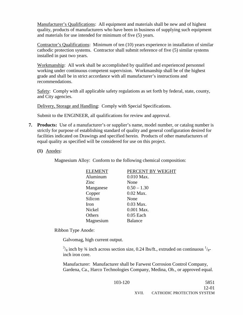
103-120 585112-01
XVII. CATHODIC PROTECTION SYSTEM
Manufacturer’s Qualifications: All equipment and materials shall be new and of highestquality, products of manufacturers who have been in business of supplying such equipmentand materials for use intended for minimum of five (5) years.
Contractor’s Qualifications: Minimum of ten (10) years experience in installation of similarcathodic protection systems. Contractor shall submit reference of five (5) similar systemsinstalled in past two years.
Workmanship: All work shall be accomplished by qualified and experienced personnelworking under continuous competent supervision. Workmanship shall be of the highestgrade and shall be in strict accordance with all manufacturer’s instructions andrecommendations.
Safety: Comply with all applicable safety regulations as set forth by federal, state, county,and City agencies.
Delivery, Storage and Handling: Comply with Special Specifications.
Submit to the ENGINEER, all qualifications for review and approval.
7. Products: Use of a manufacturer’s or supplier’s name, model number, or catalog number isstrictly for purpose of establishing standard of quality and general configuration desired forfacilities indicated on Drawings and specified herein. Products of other manufacturers ofequal quality as specified will be considered for use on this project.
(1) Anodes:
Magnesium Alloy: Conform to the following chemical composition:
ELEMENT PERCENT BY WEIGHTAluminum 0.010 Max.Zinc NoneManganese 0.50 – 1.30Copper 0.02 Max.Silicon NoneIron 0.03 Max.Nickel 0.001 Max.Others 0.05 EachMagnesium Balance
Ribbon Type Anode:
Galvomag, high current output.3/8 inch by ¾ inch across section size, 0.24 lbs/ft., extruded on continuous 1/8-inch iron core.
Manufacturer: Manufacturer shall be Farwest Corrosion Control Company,Gardena, Ca., Harco Technologies Company, Medina, Oh., or approved equal.

104-120 585112-01
XVII. CATHODIC PROTECTION SYSTEM
(2) Anode Cables:
Ribbon anodes shall be single conductor No. 8 AWG stranded copper, of requiredlength to reach each test station unspliced, complying with NFPA 70 Type HMWPEinsulation.
Cables and anodes shall be field installed as shown on Drawings.
(3) Split Bolt Connectors: Copper alloy, cold-forged type to minimum cold creep duringprolonged or extended services shall be of proper size to accommodate cable sizesbeing connected. Manufacturers shall be Burndy Company, Norwich, Ct., Penn UnionCompany, Philadelphia, Pa., or equal.
(4) Electric Tape: High voltage, self-fusing, EPR based, corrosion resistant, insulatingtape. Manufacturers shall be 3M Electric Products Division, Austin, Tx., PlymouthBishop Tapes, Canton, Ma., or approved equal.
Vinyl Electrical Tape shall be 7 mil thickness and weather resistant. Manufacturersshall be 3M Electric Products Division, Austin, Tx., Plymouth Bishop Tapes, Canton,Ma., or approved equal.
8. Test Stations: Flush mount type, consisting of:
Housing Boxes: 14 inches x 14 inches x 12 inches deep, open base with heavy duty“traffic” type cover imprinted with “CP TEST”, as manufactured by Quazite ComposoliteCompany, Lenoir City, Tennessee, or approved equal.
Test Boards: Micarta, 6 inches wide x 10 inches long x ¼ inch thick, shop fabricated withbrass hardware, as shown on Drawings.
Shunts: Calibrated magnin wire type, 0.01 ohm, and 6-ampere capacity. Holloway TypeRS.
9. Reference Electrodes:
Electrodes: 1.4 inch x 1.4 inch x 9 inches long, cast of high purity zinc in accordance withASTM B6. Supply zinc reference electrodes packaged in permeable cloth bags containing50 percent bentonite and 50 percent gypsum.
Lead Wire: Supply each zinc reference electrode with a 50-foot long lead wire of Number10 AWG stranded copper, single conductor, with yellow XHHW insulation.
Connect lead wire to the steel core of zinc reference electrode by silver soldering. Epoxyencapsulated or tape wrap connection to ensure waterproofing. Provide connection strongerthan Number 10 AWG cable being used.
10. Cable Identifications: Cable Identifications shall conform to the following: Heavy duty,non-smear, plastic impregnated cloth; resistant to moisture, dirt, and oil; withstandtemperatures from minus 400F to 275 0F, as manufactured by Panduit Electrical Group, NewLenox, Illinois, William Frick and Company, Vernon Hills, Illinois, or approved equal.

105-120 585112-01
XVII. CATHODIC PROTECTION SYSTEM
11. Exothermic Welding Equipment: Exothermic welding equipment shall be asmanufactured by ERICO Products, Inc., (CALDWELD) of Cleveland, Ohio, ContinentalIndustries, Inc. (THERMOWELD) of Tulsa, Oklahoma, or equal. Interchanging ofequipment or materials from different manufacturers will not be allowed.
Equipment: Welder size and type, weld metal charge size and type, and associated itemsused shall be as determined and recommended by manufacturer in accordance with pipematerial (i.e., steel, cast iron, ductile iron), pipe size (diameter) and wall thickness, andorientation of weld connection.
Molds must be constructed of graphite. Ceramic “one-shot” molds will not be acceptable.
Copper adapter sleeves shall be provided for all wires up to #4 AWG.
12. Weld Caps: Weld caps shall be “Handy Cap 2” as manufactured by Royston Laboratories,Inc., Pittsburgh, Pennsylvania, or approved equal. An appropriate primer shall be provided.
13. Weld Coating: Mastic weld coating shall be provided for connections to fittings, asmanufactured by TC Mastic by Tepecoat Company of Evanston, Illinois, Bitumastic No. 50by Kop-Coat Carboline Company of St. Louis, Missouri, or equal.
14. Pipe Flange Insulation Materials: Flange gasket shall be Type “E” full flange face type,constructed of neoprene faced phenolic, of proper size and ANSI pressure rating as required.Insulating Sleeves shall be Mylar, 1/32 inch thick, of proper size to fit flange bolts. Onesleeve is required for each bolt. Insulating washers shall be G3 glass phenolic, 1/8 inch thick,of proper size to fit flange bolts. Two washers are required for each bolt. For insulated pipeflanges that will be buried, use Type 304 stainless steel bolts and nuts instead of standardcarbon steel parts.
Pipe flange insulation materials shall be as manufactured by Central Plastics Company,Shawnee, Oklahoma, Pipeline Sean and Insulator, Inc., Houston, Texas, or approved equal.
15. Petrolatum Tape Wrap: Petrolatum tape wrap shall comply with AWWA C217: The firstlayer shall be plastic fiber felt saturated with petrolatums, plasticizers, and corrosioninhibitors; the second layer, shall be “rock-shield” type material, as manufactured by DensoNorth America, Inc., Houston, Texas, Trenton Corporation, Ann Arbor, Michigan, orapproved equal.
16. Execution: Furnish and install materials and equipment associates with anodes, teststations, and insulated flanges as indicated on the Drawings and described in this Section.
Ensure items furnished fit space available. Make necessary field measurements, includingthose for connections, and order such sizes and shapes of equipment in order that finalinstallation suits true intent and meaning of Drawings and Specifications.
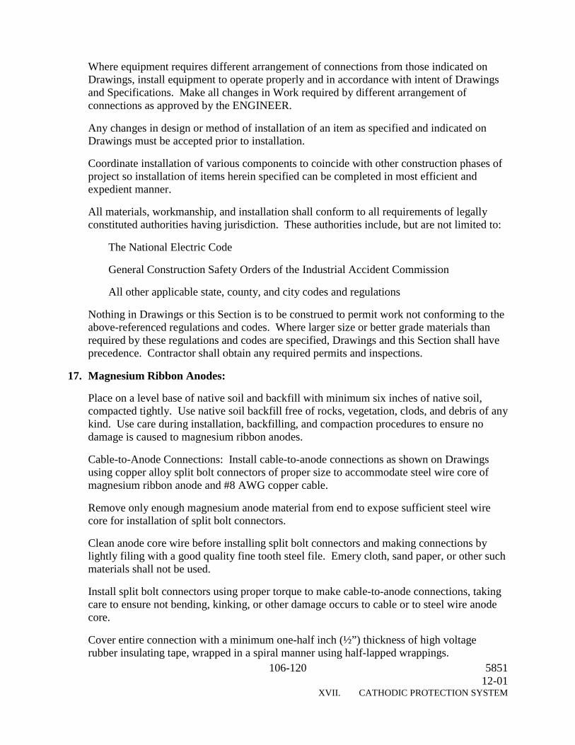
106-120 585112-01
XVII. CATHODIC PROTECTION SYSTEM
Where equipment requires different arrangement of connections from those indicated onDrawings, install equipment to operate properly and in accordance with intent of Drawingsand Specifications. Make all changes in Work required by different arrangement ofconnections as approved by the ENGINEER.
Any changes in design or method of installation of an item as specified and indicated onDrawings must be accepted prior to installation.
Coordinate installation of various components to coincide with other construction phases ofproject so installation of items herein specified can be completed in most efficient andexpedient manner.
All materials, workmanship, and installation shall conform to all requirements of legallyconstituted authorities having jurisdiction. These authorities include, but are not limited to:
The National Electric Code
General Construction Safety Orders of the Industrial Accident Commission
All other applicable state, county, and city codes and regulations
Nothing in Drawings or this Section is to be construed to permit work not conforming to theabove-referenced regulations and codes. Where larger size or better grade materials thanrequired by these regulations and codes are specified, Drawings and this Section shall haveprecedence. Contractor shall obtain any required permits and inspections.
17. Magnesium Ribbon Anodes:
Place on a level base of native soil and backfill with minimum six inches of native soil,compacted tightly. Use native soil backfill free of rocks, vegetation, clods, and debris of anykind. Use care during installation, backfilling, and compaction procedures to ensure nodamage is caused to magnesium ribbon anodes.
Cable-to-Anode Connections: Install cable-to-anode connections as shown on Drawingsusing copper alloy split bolt connectors of proper size to accommodate steel wire core ofmagnesium ribbon anode and #8 AWG copper cable.
Remove only enough magnesium anode material from end to expose sufficient steel wirecore for installation of split bolt connectors.
Clean anode core wire before installing split bolt connectors and making connections bylightly filing with a good quality fine tooth steel file. Emery cloth, sand paper, or other suchmaterials shall not be used.
Install split bolt connectors using proper torque to make cable-to-anode connections, takingcare to ensure not bending, kinking, or other damage occurs to cable or to steel wire anodecore.
Cover entire connection with a minimum one-half inch (½”) thickness of high voltagerubber insulating tape, wrapped in a spiral manner using half-lapped wrappings.

107-120 585112-01
XVII. CATHODIC PROTECTION SYSTEM
Extend high voltage rubber tape wrapping for a minimum distance of four (4) inches beyondcable-to-anode connection area in both directions, over insulation on #8 AWG cable andover magnesium anode material on the ribbon anode.
Cover high voltage rubber tape wrapping with a vinyl electrical tape wrapping of not lessthan two (2) layers applied in a spiral half-lapped manner.
Extend vinyl electrical tape wrapping at least one (1) inch beyond high voltage rubber tapewrapping in both directions.
Install cable-to-anode connections after magnesium ribbon anode lengths have beeninstalled, but before final backfilling and compaction of native soils over ribbon anodes isbegun.
Backfill cable-to-anode connections with magnesium ribbon anodes, taking care so as not tostretch or damage connections in any way. Extend #8 AWG cables from cable-to-anodeconnections above ground for installation into test stations. Provide sufficient cable at eachlocation to make installation from anode connection into test stations in one (1) continuouslength, with sufficient slack provided to minimize stress on cables during backfilling.Splicing of anode cables will not be allowed.
18. Test Stations: Install along pipeline system at locations indicated on Drawings or at 500-feet intervals, unless otherwise directed by the ENGINEER. The Drawings indicate thegeneral locations of test stations. In conjunction with the ENGINEER, determine the exactlocation of each test station based on actual site conditions and other circumstances that maybe involved.
Position each test station as accepted by the ENGINEER. Test stations shall be installedplumb and level. Test station cover shall rest firmly on the top of box and shall be level andflush with the finish grade.
Connect test station cables to pipeline and anodes in accordance with Drawings and thisSection. Connect test station cables to test boards using crimp-type ring terminals of sizerequired and type specified.
Place underground cable runs installed less than 24 inches below finish grade in conduit.Install test boards inside test boxes as indicated on Drawings, with sufficient slack in cablesto allow test boards to be lifted a minimum 24 inches out of test station.
19. Exothermic Weld Process: Observe safety precautions, welding procedures, thermite weldmaterial selection, and surface preparation as recommended by weld manufacturer. Applyexothermic welds only to tape wrapped steel pipe option. For concrete cylinder pipe, useonly factory installed lugs on bell and spigot ends, as shown on the Drawings.
(1) Preparation of Wire: Use suitable cutter to prevent deforming wire ends.
Clean oily or greasy wire with rapid-drying solvent such as natural spirits, which leavesno residue. Remove only enough insulation from wire to allow installation of coppersleeve and weld connection to be made.

108-120 585112-01
XVII. CATHODIC PROTECTION SYSTEM
(2) Preparation of Metal: Remove all coating, dirt, grime, and grease from metal at weldlocation by wire brushing and/or use of suitable safe solvents. Clean metal to bright,shiny surface free of serious pits flaws by use of mechanical grinder or file.
Area pipe where attachment is to be made must be absolutely dry.
(3) Attachment of Wire to Pipe: Comply with manufacturer’s instructions. One wire onlyis to be attached with each weld. Multiple wire-to-structure welds shall be separated byminimum of 12 inches.
(4) Testing of Completed Welds: As soon as weld has cooled, weldment shall be tested forstrength by striking several sharp, direct blows with a hammer. All unsound welds areto be re-welded and re-tested. Weld slag shall be removed from weldment with a wirebrush.
(5) Coating of All Completed Welds: Assure area to be coated is thoroughly clean by wirebrushing. Area must be completely dry. Apply bituminous mastic coating material inaccordance with manufacturer’s recommendations.
Completely coat weld, all bare pipe surfaces around weld, and any exposed copper wire.Allow sufficient time to dry. Install weld cap in accordance with manufacturer’sinstructions.
20. Reference Electrodes: Install reference electrodes at test station locations in the followingmanner and in accordance with manufacturer’s instructions:
In pipe trench, below spring line of pipe, maximum distance of 12-inches from pipe toreference electrode.
In native soil free of rocks, vegetation, and debris; with minimum 6 inches native soilbedding and minimum 6 inches native soil cover.
21. Pipe Flange Insulation: Provide pipe flanges with electrical insulating materials(insulating flange kits) at locations indicated on Drawings to provide electrical isolation ofvalves and specified sections of pipeline from other sections.
Install all flange components free of foreign materials and construction debris.
Gasket seating surfaces shall be free from tool marks, scratches, pits, deposits, or gougesgreater than regular machining marks in a circular pattern. If seating surface is damaged,machine within tolerance of flange specification. If re-machining is not possible, replaceflange.
Install insulating flange kit materials in strict accordance with manufacturer’s instructionsand recommendations. Align pipe flanges for installation of bolts, flange gasket, insulatingsleeves and washers, and metallic washers and nuts. Use lubricant or anti-seizingcompound, as recommended by insulating flange kit manufacturer, on bolt and nut threadsto provide proper engagement and facing of parts. Install bolts and associated parts finger-tight in sequence as outlined in manufacturer’s installation instructions. After installation is
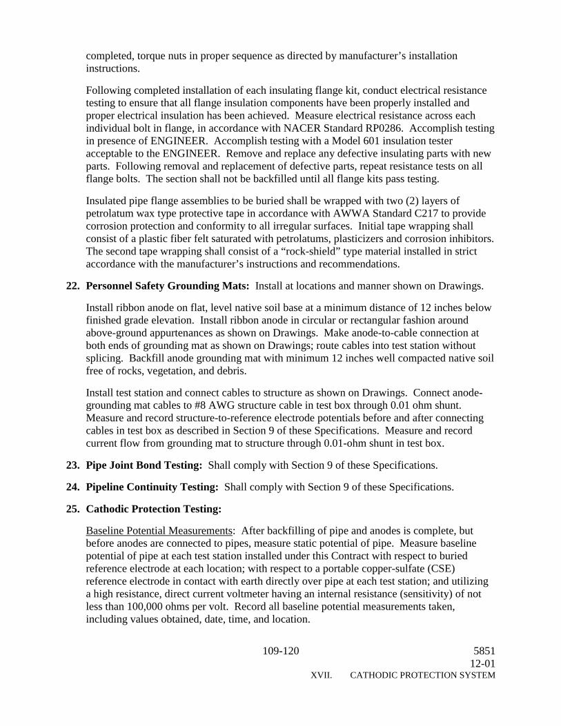
109-120 585112-01
XVII. CATHODIC PROTECTION SYSTEM
completed, torque nuts in proper sequence as directed by manufacturer’s installationinstructions.
Following completed installation of each insulating flange kit, conduct electrical resistancetesting to ensure that all flange insulation components have been properly installed andproper electrical insulation has been achieved. Measure electrical resistance across eachindividual bolt in flange, in accordance with NACER Standard RP0286. Accomplish testingin presence of ENGINEER. Accomplish testing with a Model 601 insulation testeracceptable to the ENGINEER. Remove and replace any defective insulating parts with newparts. Following removal and replacement of defective parts, repeat resistance tests on allflange bolts. The section shall not be backfilled until all flange kits pass testing.
Insulated pipe flange assemblies to be buried shall be wrapped with two (2) layers ofpetrolatum wax type protective tape in accordance with AWWA Standard C217 to providecorrosion protection and conformity to all irregular surfaces. Initial tape wrapping shallconsist of a plastic fiber felt saturated with petrolatums, plasticizers and corrosion inhibitors.The second tape wrapping shall consist of a “rock-shield” type material installed in strictaccordance with the manufacturer’s instructions and recommendations.
22. Personnel Safety Grounding Mats: Install at locations and manner shown on Drawings.
Install ribbon anode on flat, level native soil base at a minimum distance of 12 inches belowfinished grade elevation. Install ribbon anode in circular or rectangular fashion aroundabove-ground appurtenances as shown on Drawings. Make anode-to-cable connection atboth ends of grounding mat as shown on Drawings; route cables into test station withoutsplicing. Backfill anode grounding mat with minimum 12 inches well compacted native soilfree of rocks, vegetation, and debris.
Install test station and connect cables to structure as shown on Drawings. Connect anode-grounding mat cables to #8 AWG structure cable in test box through 0.01 ohm shunt.Measure and record structure-to-reference electrode potentials before and after connectingcables in test box as described in Section 9 of these Specifications. Measure and recordcurrent flow from grounding mat to structure through 0.01-ohm shunt in test box.
23. Pipe Joint Bond Testing: Shall comply with Section 9 of these Specifications.
24. Pipeline Continuity Testing: Shall comply with Section 9 of these Specifications.
25. Cathodic Protection Testing:
Baseline Potential Measurements: After backfilling of pipe and anodes is complete, butbefore anodes are connected to pipes, measure static potential of pipe. Measure baselinepotential of pipe at each test station installed under this Contract with respect to buriedreference electrode at each location; with respect to a portable copper-sulfate (CSE)reference electrode in contact with earth directly over pipe at each test station; and utilizinga high resistance, direct current voltmeter having an internal resistance (sensitivity) of notless than 100,000 ohms per volt. Record all baseline potential measurements taken,including values obtained, date, time, and location.
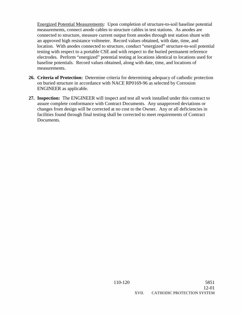
110-120 585112-01
XVII. CATHODIC PROTECTION SYSTEM
Energized Potential Measurements: Upon completion of structure-to-soil baseline potentialmeasurements, connect anode cables to structure cables in test stations. As anodes areconnected to structure, measure current output from anodes through test station shunt withan approved high resistance voltmeter. Record values obtained, with date, time, andlocation. With anodes connected to structure, conduct “energized” structure-to-soil potentialtesting with respect to a portable CSE and with respect to the buried permanent referenceelectrodes. Perform “energized” potential testing at locations identical to locations used forbaseline potentials. Record values obtained, along with date, time, and locations ofmeasurements.
26. Criteria of Protection: Determine criteria for determining adequacy of cathodic protectionon buried structure in accordance with NACE RP0169-96 as selected by CorrosionENGINEER as applicable.
27. Inspection: The ENGINEER will inspect and test all work installed under this contract toassure complete conformance with Contract Documents. Any unapproved deviations orchanges from design will be corrected at no cost to the Owner. Any or all deficiencies infacilities found through final testing shall be corrected to meet requirements of ContractDocuments.

111-120 585112-01
XVIII. PIPELINE CORROSION MONITORING FACILITIES
XVIII. PIPELINE CORROSION MONITORING FACILITIES
1. Summary: Section includes pipeline corrosion monitoring facilities, pipe joint bonding,pipe flange insulation, corrosion monitoring test stations, personnel safety grounding mats,and associated equipment, materials, and miscellaneous Items.
2. References:
ANSI C2 National Electrical Safety Code
ASTM B 3-74 (1985) Soft or Annealed Copper Wire
ASTM B 6-87 Zinc
ASTM B 418-88 Cast and Wrought Galvanic Zinc Anodes
NACE RP0169-83 Recommended Practice, Control of External Corrosion onUnderground or Submerged Metallic Piping Systems
NACE RP02086-86 Standard Recommended Practices, the Electrical Isolation ofCathodically Protected Pipelines
NEMA 250-85 Enclosures for Electrical Equipment. NFPA 70-93 NationalElectrical Code
UL 83-85 Thermoplastic-Insulated Wires
UL 467-85 Bonding and Grounding Equipment
UL 486A-85 Wire Connectors
UL 510-82 Insulating Tape
3. Definitions:
Ferrous Metal Pipe: Any pipe made of steel or iron as well as containing steel or iron as aprincipal structural material, except reinforced concrete pipe.
Foreign-Owned Structure: Any buried pipe or cable not specifically installed under thiscontract.
Lead, Lead Wire, Joint Bonds, Cable, Conductor, Insulated Copper Conductor: The same aswire.
Electrically Continuous Pipeline: A pipeline which has a linear electrical resistance equal toor less than the sum of the resistance of the pipe plus the maximum allowable bondresistance for each joint as specified in this section.
Electrical Isolation: The condition of being electrically isolated from other metallicstructures including, but not limited to, pipe, reinforcement, casing, and the environment asdefined in NACE Standard RP0169-83.
112-120 585112-01
XVIII. PIPELINE CORROSION MONITORING FACILITIES
4. Submittals: The CONTRACTOR shall submit shop drawings for all equipment andmaterials including, but not limited to, the following items: manufacturer supplied pipe jointbonding equipment, pipe joint bonding cables, test station boxes and terminal boards, teststation cables, exothermic welding equipment, exothermic weld caps, coal tar masticcoating, Zinc reference electrodes, pipe flange insulation materials, petrolatum wax tape,Magnesium ribbon anode, Ribbon anode cables, split bolt connectors, electrical tape (highvoltage rubber and vinyl), testing instruments and equipment, testing plans and schedule.
5. Delivery, Storage, and Handling: Prepare products for shipment by applying grease andlubricating oil to bearings and similar items and pack separately, mark products to agreewith delivery schedule, include complete packing lists and bills of material with eachshipment, adequately package all products to prevent damage from handling, transit, andstorage.
Materials and equipment shall be delivered in undamaged condition in the manufacturer’soriginal, unopened containers and packaging and shall be promptly inspected by theCONTRACTOR upon delivery.
All materials and equipment shall be stored as recommended by the manufacturer, includingbut not limited to providing adequate drainage, temperature control, ventilation, andprotection from the natural elements as required. Access for periodical inspection by theCONTRACTOR and ENGINEER shall be maintained.
6. Materials:
(1) Pipe Joint Bonding Equipment:
(a) Concrete Cylinder Pipe and Tape Wrapped Steel Pipe: Pipe Manufacturer suppliedbonding clips, 3 per joint, as shown on Drawings.
(b) Ductile Iron Pipe: Number 2 American Wire Gauge stranded copper, singleconductor, with high molecular weight polyethylene insulation designed for directburial and cathodic protection use, of sufficient length to avoid stress during thebackfilling of the pipe, and in the event of pipe deflection and/or movement.
Equip cables with a tinned copper sleeve on each end for connection to pipe, asshown on the Drawings.
(2) Corrosion Monitoring Test Stations: See Section 8 of these Specifications.
Test Station Cables: Number 10 AWG stranded copper, single conductor, withXHHW insulation of the color as indicated on the Drawings.
Test Station Cable Terminals: For terminating the cables inside the corrosionmonitoring test stations, use crimp-type ring terminals which are ¼ inch diameter,tinned copper, as manufactured by Thomas & Betts Corporation, Edison, NewJersey, or approved equal.
Exothermic (Thermite) Weld Equipment: See Section 8 of these Specifications.
Thermite Weld Caps: See Section 8 of these Specifications.

113-120 585112-01
XVIII. PIPELINE CORROSION MONITORING FACILITIES
Coal Tar Mastic Coating: See Section 8 of these Specifications.
Zinc Reference Electrodes: See Section 8 of these Specifications.
Pipe Flange Insulation Materials: See Section 8 of these Specifications.
Petrolatum Wax Tape Wrap: See Section 8 of these Specifications.
Magnesium Ribbon Anode for Personnel Safety Grounding Mats: See Section 8 ofthese Specifications.
Anode Cables: See Section 8 of these Specifications.
Split Bolt Connectors: See Section 8 of these Specifications.
Electrical Tape: See Section 8 of these Specifications.
7. Installation: Furnish and install all materials and equipment associated with pipe jointbonding, corrosion monitoring stations, insulated flanges, personnel safety grounding mats,and other miscellaneous items as indicated on the Plans and/or Standard Details anddescribed in this Section.
Any changes in the design or method of installation of an item as specified and indicated onthe Drawings must be accepted prior to installation.
Coordinate the installation of the various components to coincide with other constructionphases of the project so that installation of the items herein specified can be completed in themost efficient and expedient manner.
All materials, workmanship, and installation shall conform with all requirements of thelegally constituted authorities having jurisdiction. These authorities include, but are notlimited to The National Electric Code, General Construction Safety Orders of the IndustrialAccident Commission, and all other applicable, state, county, and city codes and regulations.
Nothing in the Drawings or this Section is to be construed to permit work not conforming tothe above-referenced regulations and codes. Where larger size or better grade materials thanrequired by these regulations and codes are specified, the Drawings and this Section haveprecedence. Obtain any required permits and inspections.
(1) Special Techniques:
(a) In order to form an electrically continuous pipeline facility in the areas required,bond buried and above-ground pipe joints as specified. Included in the specifiedelectrically continuous pipeline sections, bond all vault and manhole piping andfittings as necessary. Pipe joints that are to be field welded for restrainingpurposes, as specified, will not require bonding.
(b) Each bonded pipe joint shall be tested as specified in these Specifications.
(c) Concrete Cylinder Pipe and Tape Wrapped Steel Pipe: Bond all concrete cylinderpipe and steel pipe joints, except for field welded joints, to provide complete

114-120 585112-01
XVIII. PIPELINE CORROSION MONITORING FACILITIES
electrical continuity along the entire length of the pipeline system, or certainsections as specified.
Install 3 bonding clips across each concrete cylinder pipe and steel pipe joints asindicated on the Drawings.
Joint bonding connections shall be inspected and accepted by the ENGINEER priorto the application of coating or the grouting of the pipe joints.
(d) Ductile Iron Pipe, Cement Mortar Lined and Tape Coated Steel Pipe, and ConcreteCylinder Pipe:
Bond all pipe joints as indicated on the Drawings and as specified in this Section,to provide complete electrical continuity along the pipeline system.
Install 2 bonding cables across each pipe joint.
Bond pipe couplings and expansion fittings using the exothermic welding processin accordance with the manufacturer’s instructions and recommendations and instrict accordance with the details indicated on the Drawings ensuring that rings,spools, center pieces, and other associated parts are connected.
Bonding cable connections on the pipe joints and associated fittings shall beinspected by the ENGINEER before the application of coating and the backfillingof the pipe.
Coat the bonding cable connections with coal tar mastic as indicated on theDrawings and specified elsewhere in this Section.
(2) Corrosion Monitoring Test Stations: Install corrosion monitoring test stations along thepipeline system at the locations specified on the Drawings.
The Plans indicate the general locations of the test stations. In conjunction with theENGINEER, determine the exact location of each test station based on actual siteconditions and other circumstances that may be involved.
Position each test station off the streets and tin protected, accessible locations, asaccepted by the ENGINEER.
Connect test station cables to the various pipeline structures in accordance with theDrawings and this Section.
Connect test station cables to terminal boards inside the test boxes using crimp-typeterminals of the size required and the type specified herein.
Place underground cable runs installed less than 24 inches below the finish grade inconduit.
(3) Flush Mount Test Stations: Install the flush mount test stations at the locations asindicated on the Plans and/or Standard Details included in these Specifications.

115-120 585112-01
XVIII. PIPELINE CORROSION MONITORING FACILITIES
Install service boxes even with the finish grade, and bed in pea gravel. The pea gravelshall be a minimum of 6 inches deep. The pea gravel inside the service box shall be nohigher than 2 inches above the bottom of the box.
The 2-inch diameter polyvinyl chloride conduit installed inside the box shall extend nomore than 3 inches above the bottom of the box.
The test cables terminated inside the test station boxes shall each have a sufficient coilof slack cable to allow the test station terminal boards to be lifted out of the serviceboxes for a minimum distance of 24 inches.
(4) Exothermic Welding Procedures: The connection of copper cables, including bondingcables at flexible couplings and test station cables, to steel and ductile iron surfacesshall be made by the exothermic (thermite) weld method. For concrete cylinder pipe,use ring type compression connectors bolted onto pipe manufacturer installed hex headcoupling nut, as shown on the Drawings. Do not apply exothermic welds on the pipecan.
Observe proper safety precautions, welding procedures, exothermic weld materialselection, and surface preparation as recommended by the welding equipmentmanufacturer.
Assure that the pipe or fitting wall thickness is of sufficient thickness that theexothermic weld process will not damage the integrity of the pipe or fitting wall orprotective lining.
Before each connection is made, clean the surface to bare metal by making a minimum2 inch by 2 inch window in any previously applied pipeline coating, and then file orgrind the surface to reproduce a bright metal finish. Accomplish grinding with avitrified-type grinding wheel. The use of a resin, rubber, or shellac-impregnated typegrinding wheels will not be acceptable. The prepared metal surface shall be dry.
Install copper sleeves on the ends of the cables before welding to the metal surface.
(a) Remove only sufficient insulation from the cables to allow the installation of thecopper sleeves and proper placement in the welder mold.
(b) Perform thermite welding in strict accordance with the manufacturer’s writteninstructions.
(c) After the weld connection has cooled, remove all slag by wire brushing, andphysically test the cable connection by several direct blows with a hammer.Remove and replace any defective connections.
(d) After the weld is completed, trim cable insulation smooth prior to coating. Cleanwelds and surrounding area free of slag and dirt prior to coating.
(e) The completed weld connections shall be inspected and accepted by theENGINEER before final coating of the welds and backfilling of the pipe.

116-120 585112-01
XVIII. PIPELINE CORROSION MONITORING FACILITIES
Following the cleaning and testing of each weld, install a prefabricated thermite weldcap over the weld connection area. Use the proper weld cap primer for the installationof the weld cap, in strict accordance with the manufacturer’s specifications andrecommendations.
Following the installation of the thermite weld cap, coat the entire cable connectionweld area with two coats of coal tar mastic, in accordance with the manufacturer’sspecifications and instructions. Allow sufficient time between the coating applicationsto provide proper curing of the coating. Apply sufficient coating to ensure that anyexposed metal, including copper cable, is completely covered.
Completed pipe joint bonding connections and test station cable connections shall beinspected and accepted by the ENGINEER prior to the backfilling of the pipe.
(5) Zinc Reference Electrodes: Install the zinc reference electrodes at the location and inthe manner as indicated on the Drawings. Place the reference electrodes at a maximumdistance of 12 inches from the pipe.
Do not handle the reference electrodes or lower by the cable. Remove plastic or paperbags used for protection during shipping from the reference electrode beforeinstallation.
Place a minimum of 6 inches of well-compacted native soil free of rocks, clods,vegetation, and debris around the reference electrode. Saturate reference electrode,backfill, and the surrounding soil with minimum 5 gallons of water.
Any damage caused to the reference electrode or its components will requirereplacement of the entire assembly.
(6) Cable Installation: Install buried cables straight without kinks and a minimum cover of24 inches.
Install test station cables with less than 24 inches of ground cover in rigid polyvinylchloride conduit, as accepted by the ENGINEER. The bottom of the cable trench shallbe free from stones, roots, or other materials that might damage the insulation of thecables.
Install cables in conduit from the top of the pipe to the test boxes where backfill maydamage the cables.
Each cable shall be continuous in length and free of splices unless otherwise specifiedor accepted by the ENGINEER. Use care during installation to avoid abrasions,punctures, cuts, or any other damage to cable insulation. Repair or replace any damageto insulation.
(7) Pipe Flange Insulation: Provide pipe flanges with electrical insulating materials(insulating flange kits) at the locations indicated on the Drawings to provide electricalisolation of specified sections of the pipeline from the other sections.
Install all piping and piping components free of foreign materials and constructiondebris.
117-120 585112-01
XVIII. PIPELINE CORROSION MONITORING FACILITIES
The gasket seating surface shall be free from tool marks, scratches, pits, deposits, orgouges greater than the regular machining marks in a circular pattern (except of thespecified surface finish typically 125-200 AARH). If the seating surface is damaged,machine within the tolerance of the flange specification. If re-machining is notpossible, replace the flange.
Install the insulating flange kit materials in strict accordance with the manufacturer’sinstructions and recommendations.
Align pipe flanges for installation of bolts flange gasket, insulating sleeves and washers,and metallic washers and bolts. Use lubricant or anti-seizing compound, asrecommended by the insulating flange kits, on bold and nut threads to provide properengagement and facing of parts.
Install the bolts and associated parts finger-tighten in the sequence as outlined in themanufacturer'’ installation instructions. After the installation is completed, torque thestuds in the proper sequence as directed by the manufacturer’s installation instructions.
Following the completed installation of each insulating flange kit, conduct electricalresistance testing to ensure that all flange insulation components have been properlyinstalled and that proper electrical insulation has been achieved.
Measure the electrical resistance across each individual bolt assembly in accordancewith NAC Standard RP0286-86. Accomplish the testing in the presence of theENGINEER, with the pipe empty and one side of the pipe flange underground at thetime of the testing.
Accomplish the testing with a Model 601 insulation tester acceptable the ENGINEER
Remove and replace any defective insulating parts with new parts. Following theremoval and replacement of defective parts, repeat the resistance tests with all flangebolt assemblies.
Insulated pipe flange assemblies to be buried shall be wrapped with two (2) layers ofpetrolatum wax type protective tape in accordance with AWWA Standard C217 toprovide corrosion protection and conformity to all irregular surfaces.
Initial tape wrapping shall consist of plastic fiber felt saturated with petrolatumsplasticizers and corrosion inhibitors.
The second tape wrapping shall consist of a “rock-shield” type material installed instrict accordance with the manufacturer’s instructions and recommendations.
(8) Personnel Safety Grounding Mats: Comply with Section 8 of these Specifications.
8. Field Quality Control:
(1) Testing During Construction: Furnish all necessary equipment and materials and makeall electrical connections to the pipe as required to test the electrical continuity ofbonded pipe joints.
118-120 585112-01
XVIII. PIPELINE CORROSION MONITORING FACILITIES
Conduct a continuity test on each pipe joint that is required to be bonded. Test theelectrical continuity of each pipe joint before bonding and after the bonds have beeninstalled, but before backfilling of the pipe.
(a) Test Equipment Required: The CONTRACTOR shall furnish all necessary testingequipment and materials including but not limited to digital low resistance ohmmeter, as manufactured by: Biddle, Model 247001, or approved equal; one Set ofDuplex Helical Current and Potential and Spikes as manufactured by Biddle,Model Number 241001, cable length as required, or approved equal; and onecalibration shunt rated at 0.001 ohms and 100 amperes, as manufactured by Biddle,Model Number 249004, or approved equal..
Store the above described equipment at the project site and maintain the equipmentin good working condition. The equipment shall be available for use by theENGINEER or the OWNER during the construction. Upon completion of theproject, turn the equipment over to the OWNER along with all manuals andassociated items.
(b) Test Procedure: Measure the resistance of each pipe joint before and after bonding,using the low resistance ohm meter in accordance with the manufacturer’s writteninstructions.
Use the helical hand spikes to contact the pipe on each side of the joint. Whentaking measurements after the pipe joint bonding cables have been installed, do nottouch the exothermic weld or the bonding cables. Clean the contact area to brightmetal by filing or grinding, with all surface rusting or oxidation removed.
Take measurements both forward and reversed to ensure no DC interference andrecord the measured pipe joint resistances on a permanent record and submit threecopies to the ENGINEER.
Any damaged pipe coating shall be repaired in accordance with thesespecifications, using only compatible and accepted materials.
(c) Joint Bond Acceptance: Resistances of bonded pipe joints shall be less than orequal to 110 percent of the theoretical calculated resistance of the bond cables.
Replace any joint bonds which exceeds the allowable resistance. Retestreplacement joint bonds for compliance with the specified bond resistance.
(d) Test Records: Maintain a complete record of all resistance testing conducted ateach pipe joint, before and after joint bonding cables have been installed.
Submit the original and five copies of the test data to the ENGINEER forevaluation within 24 hours after the testing has been completed.
The test records shall include: the location (pipeline station number) and a briefdescription of the joint type, fitting; the date of the test and the status of the joint(before or after bonding); the resistance measured; and any comments.

119-120 585112-01
XVIII. PIPELINE CORROSION MONITORING FACILITIES
Notify the ENGINEER at least 24 hours before pipe joint resistance testing is to beconducted, in order that the testing may be witnessed by the ENGINEER.
(2) Testing after Construction: Perform electrical continuity testing on the entire bondedpipeline system or specified bonded sections of the pipeline system installed as part ofproject to ascertain and ensure that all pipe joint bonding has been properly installedand is functioning as designated.
Complete the continuity testing after the pipe joint bonding and installation of thecorrosion monitoring test stations have been completed.
The CONTRACTOR shall provide all required testing equipment and materials,including but not limited to the following: 1 Each Digital Multimeter with Case andTest Leads, as manufactured by Beckham Instruments, San Diego, California, ModelHD-100, or approved equal; 2 Each Copper/copper-sulfate Reference Electrodes, asmanufactured by Tinker & Rasor, Inc., San Gabriel, California, Model 8B, or approvedequal; 1 Pound Copper Sulfate Crystals, as manufactured by Tinker & Rasor, Inc., SanGabriel, California, or approved equal; and one Quart Copper Sulfate Anti-freezeSolution, as manufactured by Tinker & Rasor, Inc., San Gabriel, California, or approvedequal.
The CONTRACTOR shall ensure that all required testing equipment be available at thesite well in advance to the continuity testing is scheduled to begin.
Store equipment at the project site and maintain the equipment in good workingcondition. The equipment shall be available for use by ENGINEER or the OWNER.Turn the equipment over to the OWNER along with all manuals and associated itemsupon completion of the project.
At least 3 weeks before continuity testing is to be accomplished, submit a testing planand schedule to the ENGINEER. This plan and schedule shall include a list of theequipment that will be used for the testing, including power supply, auxiliary(temporary) ground, reference electrode, Voltmeters.
(a) Testing Procedure: Conduct the continuity tests by measuring the response of thepotential of the piping to the application of a simulated cathodic protection testcurrent in the following manner:
Install an auxiliary (temporary) ground at a minimum distance of 10 feet from thepipeline near or adjacent to a corrosion monitoring test station.
Connect the auxiliary ground to the positive DC output terminal of a portablecathodic protection rectifier unit or “steady source” DC power supply, as acceptedby the ENGINEER.
Connect the negative DC output terminal of the rectifier or DC power supply to thepipeline by means of the test cables in the corrosion monitoring test station.
Adjust the DC output of the rectifier or power supply to provide a pipeline potentialno more negative than minus 2.00 volts with respect to a standard copper/copper-

120-120 585112-01
XVIII. PIPELINE CORROSION MONITORING FACILITIES
sulfate (Cu/CuSO4) reference electrode in contact with the earth directly over thepipeline at the test station location.
Record the DC voltage and current output of the rectifier or power supply, alongwith the pipeline- potential measured at or near the auxiliary ground.
With the DC test current turned on and off on a cycling basis (by means of acurrent interrupter installed in the test circuit), “on” and “off” pipe-to-Cu/CuSO4potential measurements shall be taken at each corrosion monitoring test station inboth directions away from the auxiliary ground and power source.
Pipe-to-Cu/CuSO4 potential measurements of “foreign” lines and/or casings locatedat test stations shall also be taken with the simulated cathodic protection current“on” and “off”.
All measurements shall be recorded.
When the pipe-to-Cu/CuSO4 potential change from “off” to “on” becomes less than300 millivolts, move the auxiliary ground and the power supply to a new location,with the testing procedure as described above, repeated until the entire bondedpipeline or bonded pipeline sections have been tested.
Take all pipe-to-Cu/CuSO4 potential measurements utilizing the Digital Multimeterand the copper/copper-sulfate reference electrodes to be purchased by theContractor as part of the
project, and as specified earlier in this Section.
Accomplish all continuity testing in the presence of the ENGINEER.
9. Inspection: Upon completion of all work, the corrosion control facilities installed underthis contract will be inspected and tested by the ENGINEER to assure completeconformance with the Contract Documents.
Any unapproved deviations or changes from the design made by the CONTRACTOR duringthe installation of these facilities shall be corrected.
Any or all deficiencies in the facilities found through the final testing shall be corrected tomeet the requirements of the Contract Documents.