Embed Size (px)
Citation preview
CSM_DZ_DS_E_4_3
1
Special-purpose Basic Switch
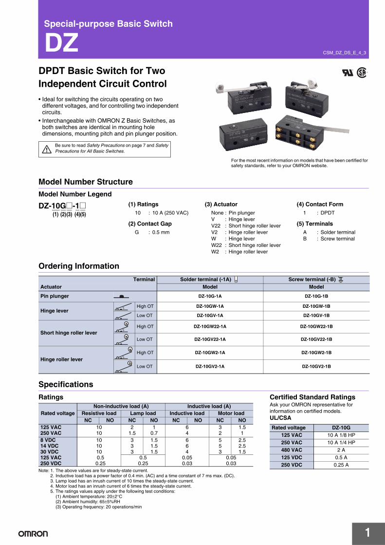
DZDPDT Basic Switch for Two Independent Circuit Control• Ideal for switching the circuits operating on two
different voltages, and for controlling two independent circuits.
• Interchangeable with OMRON Z Basic Switches, as both switches are identical in mounting hole dimensions, mounting pitch and pin plunger position.
Be sure to read Safety Precautions on page 7 and Safety Precautions for All Basic Switches.
For the most recent information on models that have been certified for safety standards, refer to your OMRON website.
Model Number StructureModel Number Legend
Ordering Information
Specifications
Terminal Solder terminal (-1A) Screw terminal (-B) Actuator Model Model
Pin plunger DZ-10G-1A DZ-10G-1B
Hinge leverHigh OT DZ-10GW-1A DZ-10GW-1B
Low OT DZ-10GV-1A DZ-10GV-1B
Short hinge roller leverHigh OT DZ-10GW22-1A DZ-10GW22-1B
Low OT DZ-10GV22-1A DZ-10GV22-1B
Hinge roller leverHigh OT DZ-10GW2-1A DZ-10GW2-1B
Low OT DZ-10GV2-1A DZ-10GV2-1B
(1) Ratings10 : 10 A (250 VAC)
(2) Contact GapG : 0.5 mm
(3) ActuatorNone : Pin plungerV : Hinge leverV22 : Short hinge roller leverV2 : Hinge roller leverW : Hinge leverW22 : Short hinge roller leverW2 : Hinge roller lever
(4) Contact Form1 : DPDT
(5) TerminalsA : Solder terminalB : Screw terminal
DZ-10G@-1@(1) (2)(3) (4)(5)
Ratings
Note: 1. The above values are for steady-state current.2. Inductive load has a power factor of 0.4 min. (AC) and a time constant of 7 ms max. (DC).3. Lamp load has an inrush current of 10 times the steady-state current.4. Motor load has an inrush current of 6 times the steady-state current.5. The ratings values apply under the following test conditions:
(1) Ambient temperature: 20±2°C(2) Ambient humidity: 65±5%RH(3) Operating frequency: 20 operations/min
Rated voltageNon-inductive load (A) Inductive load (A)
Resistive load Lamp load Inductive load Motor loadNC NO NC NO NC NO NC NO
125 VAC250 VAC
1010
21.5
10.7
64
32
1.51
8 VDC14 VDC30 VDC125 VAC250 VDC
1010100.5
0.25
333
1.51.51.5
664
0.050.03
553
2.52.51.5
0.50.25
0.050.03
Certified Standard RatingsAsk your OMRON representative for information on certified models.UL/CSARated voltage DZ-10G
125 VAC 10 A 1/8 HP250 VAC 10 A 1/4 HP480 VAC 2 A125 VDC 0.5 A250 VDC 0.25 A

2
DZ
StructureContact Form (DPDT)
Dimensions (Unit: mm)
TerminalsSolder Terminals (-1A) Screw Terminals (-1B)
Dimensions and Operating CharacteristicsThe solder terminal model has a suffix "-1A" in its model number and its omitted dimensions are the same as the corresponding dimensions of the pin plunger model.
Characteristics
*1. The values are for pin plunger models. (Contact your OMRON representative for other models.)*2. Malfunction: 1 ms max.
Contact Specifications
Operating speed 0.1 mm to 1 m/s *1
Operating frequency
Mechanical 240 operations/minElectrical 20 operations/min
Insulation resistance 100 MΩ min. (at 500 VDC)Contact resistance 15 mΩ max. (initial value)
Dielectric strength
1,000 VAC, 50/60 Hz for 1 min between non-continuous terminals1,500 VAC, 50/60 Hz for 1 min between current-carryingmetal parts and non-current-carrying metal part, and between current-carrying metal part and ground and between switches
Vibrationresistance Malfunction 10 to 55 Hz, 1.5-mm double amplitude *2
Shockresistance
Destruction 1,000 m/s2 max.Malfunction 300 m/s2 max. *1 *2
DurabilityMechanical 1,000,000 operations min.Electrical 500,000 operations min.
Degree of protection IP00Degree of protection against electric shock Class I
Proof tracking index (PTI) 175Ambient operating temperature −25°C to 80°C (with no icing)Ambient operating humidity 35% to 85%RHWeight Approx. 30 to 50 g
ContactsMaterial Silver alloyGap (standard value) 0.5 mm
Inrush currentNC 30 A max.NO 15 A max.
Engineering DataMechanical Durability (DZ-10G-1B)
Electrical Durability (DZ-10G-1B)
10,000
7,000
5,000
3,000
1,000
700
500
300
1000 0.1 0.2 0.3 0.4 0.5 0.6 0.7 0.8
Overtravel (mm)
Dur
abili
ty (
x104 o
pera
tions
)
Ambient temperature: 20±2°CAmbient humidity: 65±5%RHWithout loadOperating frequency: 240 operations/min
1,000
700
500
300
100
70
50
30
100 5 10 15
Switching current (A)
250 VAC
125 VAC
Dur
abili
ty (
x104 o
pera
tions
)
Ambient temperature: 20±2°CAmbient humidity: 65±5%RHOperating frequency: 20 operations/mincosφ=1
COM2 NC2
NO2
COM1 NC1
NO1
NC NOCOM
NC NOCOM
17.45±0.225.4±0.1
11.949.2
8.2
14.5
23.5 16.8
COM NC NO
COM NC NO
17.45±0.225.4±0.1
11.949.2
8.2
14.5
23.5 16.8
Six M3 pan head screws(with toothed washer)
4.2 dia. hole+0.075-0.025
4.36 dia.+0.1-0.05
4.2+0.075-0.025
23.3±0.25
25.4±0.111.9
49.2
17.45±0.2
PT
OP
3 dia. 2.5SR *
0.4
14.5
8.2
* Stainless-steel pin plunger
Pin Plunger
DZ-10G-1B
Operating force OF max.Release force RF min.Pretravel PT max.Overtravel OT min.Movement Differential MD max.
5.59 N0.56 N1.7 mm0.13 mm0.4 mm
Operating Position OP 15.6±0.4 mm

3
DZ
Note: Unless otherwise specified, a tolerance of ±0.4 mm applies to all dimensions.
28.4
25.4±0.111.9
49.2
17.45±0.2
17.719.714.5
FP
8.2
OP
4.9
* Stainless-steel lever
t = 1 *
63.5R
4.2 dia. hole+0.075-0.025
4.36 dia.+0.1-0.05
4.2+0.075-0.025
Hinge Lever
DZ-10GW-1B
OF max.RF min.OT min.MD max.
1.67 N0.27 N1.6 mm4 mm
FP max.OP
46.3 mm21.8±1 mm
17.45 ±0.2
4.9
* Stainless-steel lever
25.4±0.111.9
49.2
17.7
4.2 dia. hole+0.075-0.025
4.36 dia.+0.1-0.05
4.2+0.075-0.025
19.714.5
8.2
OP
PT t = 1 *63.5R
1.1DZ-10GV-1B
OF max.RF min.PT max.OT min.MD max.
1.96 N0.13 N6 mm
0.4 mm1.7 mm
OP 18.3±1 mm
4.2 dia. hole+0.075-0.025
4.36 dia.+0.1-0.05
4.2+0.075-0.025
28.4
25.4±0.111.9
49.2
17.45±0.2
17.719.714.5
FP
8.2
OP
9.5 dia. × 4(plastic roller)
* Stainless-steel lever
t = 1 *
26.2
R
Short Hinge Roller LeverDZ-10GW22-1B
OF max.RF min.OT min.MD max.
3.92 N0.83 N0.9 mm2.4 mm
FP max.OP
39.7 mm30.2±0.8 mm
17.45±0.2
* Stainless-steel lever
4.2 dia. hole+0.075-0.025
4.36 dia.+0.1-0.05
25.4±0.111.9
49.2
17.7 19.714.5
8.2
OP
PT
4.2+0.075-0.025
t = 1 *
1.1
9.5 dia. × 4(plastic roller)
30.2R
DZ-10GV22-1B
OF max.RF min.PT max.OT min.MD max.
4.22 N0.41 N3 mm
0.13 mm0.6 mm
OP 29.4±0.8 mm
28.4
25.4±0.111.9
49.2
17.45±0.2
17.719.714.5
FP
8.2
OP
9.5 dia. × 4(plastic roller)
* Stainless-steel lever
t = 1 *
48.4R
4.2 dia. hole+0.075-0.025
4.36 dia.+0.1-0.05
4.2+0.075-0.025
17.45±0.2
* Stainless-steel lever
4.2 dia. hole+0.075-0.025
4.36 dia.+0.1-0.05
25.4±0.111.9
49.2
17.7 19.714.5
8.2
OP
PT t = 1 *
1.1
9.5 dia. × 4(plastic roller)
48.4R
4.2+0.075-0.025
OF max.RF min.PT max.OT min.MD max.
2.65 N0.33 N4 mm
0.26 mm1.1 mm
OP 29.4±0.8 mm
Hinge Roller Lever
DZ-10GW2-1B
OF max.RF min.OT min.MD max.
2.09 N0.41 N1.2 mm3.3 mm
FP max.OP
47.6 mm31.8±0.8 mm
DZ-10GV2-1B
4
DZAccessories (Order separately)
A Terminal Protective Cover, Actuators, and a Separator are available.
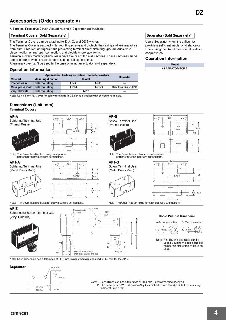
Dimensions (Unit: mm)Terminal Covers
Note: Each dimension has a tolerance of ±0.4 mm unless otherwise specified. (±0.8 mm for the AP-Z)
The Terminal Covers can be attached to Z, A, X, and DZ Switches.The Terminal Cover is secured with mounting screws and protects the casing and terminal wires from dust, vibration, or fingers, thus preventing terminal short-circuiting, ground faults, wire disconnection or improper connection, and electric shock accidents.Terminal Covers made of phenol resin have five or six thin wall sections. These sections can be torn open for providing holes for lead cables at desired points.A terminal cover can’t be used in the case of using an actuator sold separately.
Operation Information
Note: Use a Terminal Cover for screw terminals fir DZ-series Switches with soldering terminals.
Terminal Covers (Sold Separately)
Application Soldering terminal use Screw terminal useRemarks
Material Mounting direction Model
Phenol resin Side mounting AP-A AP-B ---
Metal press mold Side mounting AP1-A AP1-B Used for AP-A and AP-B
Vinyl chloride Side mounting AP-Z ---
Use a Separator when it is difficult to provide a sufficient insulation distance or when using the Switch near metal parts or copper wires.
Operation Information
Separator (Sold Separately)
Model
SEPARATOR FOR Z
52.8
25.4
8
6.5
16.3
218
2.15R
4.3+0.20 4.3+0.2
0
AP-ASoldering Terminal Use(Phenol Resin)
Note: The Cover has five thin, easy-to-separate portions for easy lead wire connections.
53.825.4
8
6.5
20.2
218
2.15R
4.3+0.20 4.3+0.2
0AP-BScrew Terminal Use(Phenol Resin)
Note: The Cover has six thin, easy-to-separate portions for easy lead wire connections.
54.425.4
8
7.2
17.1
22.68.5
2.15R
4.3+0.20 4.3+0.2
0
AP1-ASoldering Terminal Use(Metal Press Mold)
Note: The Cover has five holes for easy lead wire connections.
55.425.4
8
7
21
22.68.5
2.15R
4.3+0.20 4.3+0.2
0AP1-BScrew Terminal Use(Metal Press Mold)
Note: The Cover has six holes for easy lead wire connections.
14
21
52.8
25.4
21
3946
7
1213
15
A'
B'
A
B
Pressure plate(t1 steel)
Two, 4.2 dia.
M3 × 20 Phillips screw(with plane washer and nut)Nut
15 13
A-A' cross-section B-B' cross-section
8 dia. 6 dia.
Note: A 6-dia. or 8-dia. cable can be used by cutting the cable pull-out hole to the size of the cable to be used.
Cable Pull-out Dimension
AP-ZSoldering or Screw Terminal Use(Vinyl Chloride)
25.4±0.211.9
27±0.5
13.5
49.2±0.5
Two, 4.5 dia.
t = 0.51
Note: 1. Each dimension has a tolerance of ±0.4 mm unless otherwise specified.2. The material is EAVTC (Epoxide Alkyd Varnished Tetron Cloth) and its heat-resisting
temperature is 130°C.
Separator

5
DZ
A Switch can be actuated by a cam or an appropriate object, in which case, use one of the following Actuators according to the application.
Ordering Information
Dimensions (Unit: mm) and Operating Characteristics Note: These Actuators are not provided with Switches.
Note: Each dimension has a tolerance of ±0.4 mm unless otherwise specified.
Actuators (Sold Separately)
Actuator Application Common to Z and X models
Hinge lever XAA-1
Hinge roller lever ZAA-2
Panel mount plunger
Short ZAQ-3
Medium ZAQ-2
Long ZAQ-1
Panel mount roller plunger ZAQ-22
49.2
11.9
20.529.4
38.5
19.1
7
OP
60R
FP
*
25.4±0.1
Two, M4 Two, M4 30
* Stainless steel
Note: This Actuator can be used with the Z-15G(-B) and X-10G(-B). When mounting the Switch, set the overtravel to between 32% and 100%, taking into consideration the operating body and the distance between the Actuator and the dog.
ModelOperating characteristics Z-15G-B X-10G-B
Operating force OF max.Release force RF min.Overtravel OT min.Movement Differential MD max.
4.90 N1.67 N
12.7 mm2.2 mm
4.90 N1.67 N
12.7 mm3.3 mm
Free Position FP max.Operating Position OP
32.9±1.6 mm28.9±1.6 mm
Hinge LeverXAA-1
XAA-1
XAA-1
49.2
11.9
20.529.4
38.5
19.1
22.2
7
*2
OP FP
58.5R
25.4±0.1
Two, M4 Two, M4 30
*1. Stainless steel roller*2. Stainless steel
9.5 dia. × 4.8 *1
Hinge Roller LeverZAA-2
Note: This Actuator can be used with the Z-15G(-B) and ZX-10G(-B). When mounting the Switch, set the overtravel to between 32% and 100%, taking into consideration the operating body and the distance between the Actuator and the dog.
Z-15G-B X-10G-B
OF max.RF min.OT min.MD max.
4.90 N1.67 N
12.7 mm2.2 mm
4.90 N1.67 N
12.7 mm3.3 mm
FP max.OP
44.5±1.6 mm40.4±1.6 mm
52.4
13.5
20.7
1.6
OP
PT
23.312SR
*1
20.7
24.222.6
17.5
*3*2
*3
25.4±0.1
M12 × 1 mounting screw
2 t × 15.6 widthacross flats
*1. Stainless-steel pin plunger*2. Bronze frame*3. Incomplete screw section part with a maximum of 1.5 mm
7.9 dia.
2 t × 14 width across flats
Two, M4 × 25 screws
Two, M4 nuts
14.5dia.
Short Panel Mount PlungerZAQ-3
Note: 1. This Actuator (pin plunger) can be used with Standard Pin Plungers (Z-15G(-B), Z-15E(-B), X-10G(-B), DZ-10G-1A(-1B)) for the Z, X, and DZ models.
ZAQ-3
Z-15E-B X-10G-B
OF max.RF min.PT max.OT min.MD max.
8.34 N1.12 N0.8 mm4.8 mm
0.15 mm
5.39 N1.12 N1 mm
4.5 mm0.2 mm
OP 27.8±1.5 mm
6
DZ
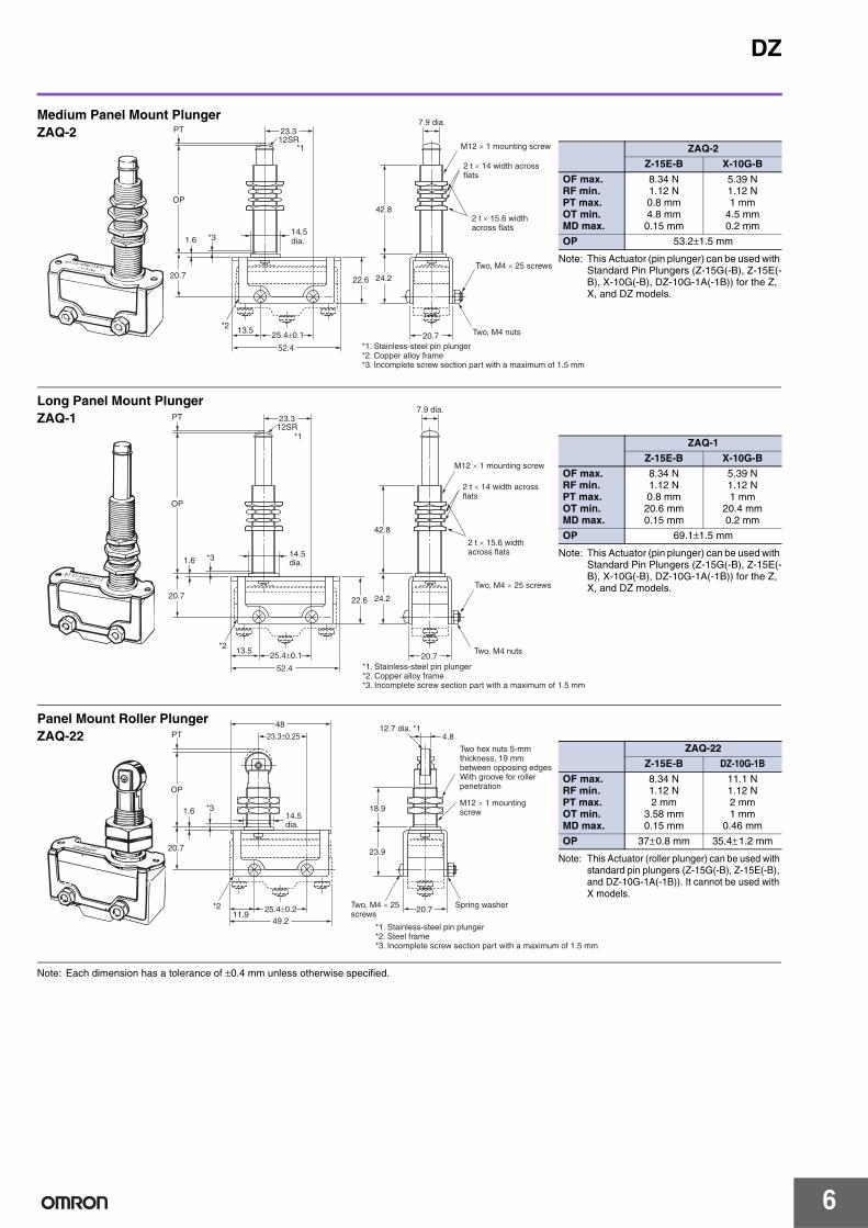
Note: Each dimension has a tolerance of ±0.4 mm unless otherwise specified.
52.4
13.5
20.7
1.6 *3
*2
OP
PT 23.312SR
20.7
24.222.6
42.8
*1
25.4±0.1
M12 × 1 mounting screw
2 t × 15.6 widthacross flats
*1. Stainless-steel pin plunger*2. Copper alloy frame*3. Incomplete screw section part with a maximum of 1.5 mm
7.9 dia.
2 t × 14 width acrossflats
Two, M4 × 25 screws
Two, M4 nuts
14.5dia.
Note: This Actuator (pin plunger) can be used with Standard Pin Plungers (Z-15G(-B), Z-15E(-B), X-10G(-B), DZ-10G-1A(-1B)) for the Z, X, and DZ models.
ZAQ-2
Z-15E-B X-10G-B
OF max.RF min.PT max.OT min.MD max.
8.34 N1.12 N0.8 mm4.8 mm0.15 mm
5.39 N1.12 N1 mm
4.5 mm0.2 mm
OP 53.2±1.5 mm
Medium Panel Mount PlungerZAQ-2
52.4
13.5
20.7
1.6
OP
PT 23.312SR
*1
20.7
24.222.6
42.8
*3
*225.4±0.1
M12 × 1 mounting screw
2 t × 15.6 widthacross flats
*1. Stainless-steel pin plunger*2. Copper alloy frame*3. Incomplete screw section part with a maximum of 1.5 mm
14.5dia.
7.9 dia.
2 t × 14 width acrossflats
Two, M4 × 25 screws
Two, M4 nuts
Long Panel Mount PlungerZAQ-1
Note: This Actuator (pin plunger) can be used with Standard Pin Plungers (Z-15G(-B), Z-15E(-B), X-10G(-B), DZ-10G-1A(-1B)) for the Z, X, and DZ models.
ZAQ-1
Z-15E-B X-10G-B
OF max.RF min.PT max.OT min.MD max.
8.34 N1.12 N0.8 mm20.6 mm0.15 mm
5.39 N1.12 N1 mm
20.4 mm0.2 mm
OP 69.1±1.5 mm
48
OP
PT
20.7
1.6 *3
*2
23.3±0.25
23.9
4.8
20.711.9
49.225.4±0.2
18.9M12 × 1 mountingscrew
Two, M4 × 25 screws
*1. Stainless-steel pin plunger*2. Steel frame*3. Incomplete screw section part with a maximum of 1.5 mm
12.7 dia. *1
Two hex nuts 5-mm thickness, 19 mmbetween opposing edgesWith groove for roller penetration
Spring washer
14.5dia.
Note: This Actuator (roller plunger) can be used with standard pin plungers (Z-15G(-B), Z-15E(-B), and DZ-10G-1A(-1B)). It cannot be used with X models.
ZAQ-22
Z-15E-B DZ-10G-1B
OF max.RF min.PT max.OT min.MD max.
8.34 N1.12 N2 mm
3.58 mm0.15 mm
11.1 N1.12 N2 mm1 mm
0.46 mm
OP 37±0.8 mm 35.4±1.2 mm
Panel Mount Roller PlungerZAQ-22
7
DZSafety PrecautionsRefer to Safety Precautions for All Basic Switches.
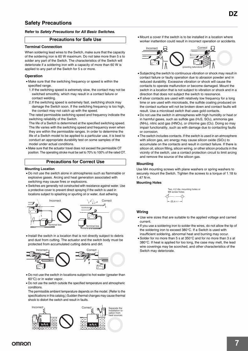
Terminal ConnectionWhen soldering lead wires to the Switch, make sure that the capacity of the soldering iron is 60 W maximum. Do not take more than 5 s to solder any part of the Switch. The characteristics of the Switch will deteriorate if a soldering iron with a capacity of more than 60 W is applied to any part of the Switch for 5 s or more.
Operation• Make sure that the switching frequency or speed is within the
specified range.1.If the switching speed is extremely slow, the contact may not be
switched smoothly, which may result in a contact failure or contact welding.
2.If the switching speed is extremely fast, switching shock may damage the Switch soon. If the switching frequency is too high, the contact may not catch up with the speed.
The rated permissible switching speed and frequency indicate the switching reliability of the Switch.The life of a Switch is determined at the specified switching speed. The life varies with the switching speed and frequency even when they are within the permissible ranges. In order to determine the life of a Switch model to be applied to a particular use, it is best to conduct an appropriate durability test on some samples of the model under actual conditions.
• Make sure that the actuator travel does not exceed the permissible OT position. The operating stroke must be set to 70% to 100% of the rated OT.
Mounting Location• Do not use the switch alone in atmospheres such as flammable or
explosive gases. Arcing and heat generation associated with switching may cause fires or explosions.
• Switches are generally not constructed with resistance against water. Use a protective cover to prevent direct spraying if the switch is used in locations subject to splashing or spurting oil or water, dust adhering.
• Install the switch in a location that is not directly subject to debris and dust from cutting. The actuator and the switch body must be protected from accumulated cutting debris and dirt.
• Do not use the switch in locations subject to hot water (greater than 60°C) or in water vapor.
• Do not use the switch outside the specified temperature and atmospheric conditions.The permissible ambient temperature depends on the model. (Refer to the specifications in this catalog.) Sudden thermal changes may cause thermal shock to distort the switch and result in faults.
• Mount a cover if the switch is to be installed in a location where worker inattention could result in incorrect operation or accidents.
• Subjecting the switch to continuous vibration or shock may result in contact failure or faulty operation due to abrasion powder and in reduced durability. Excessive vibration or shock will cause the contacts to operate malfunction or become damaged. Mount the switch in a location that is not subject to vibration or shock and in a direction that does not subject the switch to resonance.
• If silver contacts are used with relatively low frequency for a long time or are used with microloads, the sulfide coating produced on the contact surface will not be broken down and contact faults will result. Use a microload switch that uses gold contacts.
• Do not use the switch in atmospheres with high humidity or heat or in harmful gases, such as sulfide gas (H2S, SO2), ammonia gas (NH3), nitric acid gas (HNO3), or chlorine gas (Cl2). Doing so may impair functionality, such as with damage due to contacting faults or corrosion.
• The switch includes contacts. If the switch is used in an atmosphere with silicon gas, arc energy may cause silicon oxide (SiO2) to accumulate on the contacts and result in contact failure. If there is silicon oil, silicon filling, silicon wiring, or other silicon products in the vicinity of the switch, use a contact protection circuit to limit arcing and remove the source of the silicon gas.
MountingUse M4 mounting screws with plane washers or spring washers to securely mount the Switch. Tighten the screws to a torque of 1.18 to 1.47 N·m.Mounting Holes
Wiring• Use wire sizes that are suitable to the applied voltage and carried
current.• If you use a soldering iron to solder the wires, do not allow the tip of
the soldering iron to exceed 380°C. If a Switch is used with insufficient soldering, abnormal heat and burning may occur.
• Solder for no more than 5 s at 350°C and for no more than 3 s at 380°C. If heat is applied for too long, the case may melt, the lead wire coverings may be scorched, and other characteristics of the Switch may deteriorate.
Precautions for Safe Use
Precautions for Correct Use
Terminal box Terminal box
Incorrect Correct
Incorrect Correct
Incorrect Separate the installation lo-cation from heat sources.
Correct
Correct
(preventing malfunctions)
Incorrect
25.4 ±0.1
Two, 4.2 dia. mounting holes orM4 screw holes
Terms and Conditions Agreement Read and understand this catalog. Please read and understand this catalog before purchasing the products. Please consult your OMRON representative if you have any questions or comments. Warranties. (a) Exclusive Warranty. Omron’s exclusive warranty is that the Products will be free from defects in materials and workmanship for a period of twelve months from the date of sale by Omron (or such other period expressed in writing by Omron). Omron disclaims all other warranties, express or implied. (b) Limitations. OMRON MAKES NO WARRANTY OR REPRESENTATION, EXPRESS OR IMPLIED, ABOUT NON-INFRINGEMENT, MERCHANTABILITY OR FITNESS FOR A PARTICULAR PURPOSE OF THE PRODUCTS. BUYER ACKNOWLEDGES THAT IT ALONE HAS DETERMINED THAT THE PRODUCTS WILL SUITABLY MEET THE REQUIREMENTS OF THEIR INTENDED USE. Omron further disclaims all warranties and responsibility of any type for claims or expenses based on infringement by the Products or otherwise of any intellectual property right. (c) Buyer Remedy. Omron’s sole obligation hereunder shall be, at Omron’s election, to (i) replace (in the form originally shipped with Buyer responsible for labor charges for removal or replacement thereof) the non-complying Product, (ii) repair the non-complying Product, or (iii) repay or credit Buyer an amount equal to the purchase price of the non-complying Product; provided that in no event shall Omron be responsible for warranty, repair, indemnity or any other claims or expenses regarding the Products unless Omron’s analysis confirms that the Products were properly handled, stored, installed and maintained and not subject to contamination, abuse, misuse or inappropriate modification. Return of any Products by Buyer must be approved in writing by Omron before shipment. Omron Companies shall not be liable for the suitability or unsuitability or the results from the use of Products in combination with any electrical or electronic components, circuits, system assemblies or any other materials or substances or environments. Any advice, recommendations or information given orally or in writing, are not to be construed as an amendment or addition to the above warranty. See http://www.omron.com/global/ or contact your Omron representative for published information. Limitation on Liability; Etc. OMRON COMPANIES SHALL NOT BE LIABLE FOR SPECIAL, INDIRECT, INCIDENTAL, OR CONSEQUENTIAL DAMAGES, LOSS OF PROFITS OR PRODUCTION OR COMMERCIAL LOSS IN ANY WAY CONNECTED WITH THE PRODUCTS, WHETHER SUCH CLAIM IS BASED IN CONTRACT, WARRANTY, NEGLIGENCE OR STRICT LIABILITY. Further, in no event shall liability of Omron Companies exceed the individual price of the Product on which liability is asserted. Suitability of Use. Omron Companies shall not be responsible for conformity with any standards, codes or regulations which apply to the combination of the Product in the Buyer’s application or use of the Product. At Buyer’s request, Omron will provide applicable third party certification documents identifying ratings and limitations of use which apply to the Product. This information by itself is not sufficient for a complete determination of the suitability of the Product in combination with the end product, machine, system, or other application or use. Buyer shall be solely responsible for determining appropriateness of the particular Product with respect to Buyer’s application, product or system. Buyer shall take application responsibility in all cases. NEVER USE THE PRODUCT FOR AN APPLICATION INVOLVING SERIOUS RISK TO LIFE OR PROPERTY OR IN LARGE QUANTITIES WITHOUT ENSURING THAT THE SYSTEM AS A WHOLE HAS BEEN DESIGNED TO ADDRESS THE RISKS, AND THAT THE OMRON PRODUCT(S) IS PROPERLY RATED AND INSTALLED FOR THE INTENDED USE WITHIN THE OVERALL EQUIPMENT OR SYSTEM. Programmable Products. Omron Companies shall not be responsible for the user’s programming of a programmable Product, or any consequence thereof. Performance Data. Data presented in Omron Company websites, catalogs and other materials is provided as a guide for the user in determining suitability and does not constitute a warranty. It may represent the result of Omron’s test conditions, and the user must correlate it to actual application requirements. Actual performance is subject to the Omron’s Warranty and Limitations of Liability. Change in Specifications. Product specifications and accessories may be changed at any time based on improvements and other reasons. It is our practice to change part numbers when published ratings or features are changed, or when significant construction changes are made. However, some specifications of the Product may be changed without any notice. When in doubt, special part numbers may be assigned to fix or establish key specifications for your application. Please consult with your Omron’s representative at any time to confirm actual specifications of purchased Product. Errors and Omissions. Information presented by Omron Companies has been checked and is believed to be accurate; however, no responsibility is assumed for clerical, typographical or proofreading errors or omissions.
2016.3
In the interest of product improvement, specifications are subject to change without notice.
OMRON Corporation Industrial Automation Company http://www.ia.omron.com/
(c)Copyright OMRON Corporation 2016 All Right Reserved.


![Basic Switch – [Preliminary]. 2Honeywell Confidential Opening Introduction Fundamental of Basic Switch Products Overview Product Selection Competitors](https://img.dokumen.tips/doc/110x75/56649ca25503460f94961de9/basic-switch-preliminary-2honeywell-confidential-opening-introduction.jpg)