Embed Size (px)
Citation preview

Lewiston Auburn Transportation Committee WIN 12326.00
Federal Number: ME03-0041 Downtown Auburn Transportation Center
Date: May 27, 2015
CAST-IN-PLACE CONCRETE 033000 - 1
SPECIAL PROVISION SECTION 033000 CAST-IN-PLACE CONCRETE
PART 1 - GENERAL
1.1 SUMMARY
A. Section includes cast-in-place concrete, including formwork, reinforcement, concrete materials, mixture design, placement procedures, and finishes.
B. Related Requirements:
1. Section 312000 "Earth Moving" for drainage fill under slabs-on-grade.
1.2 ACTION SUBMITTALS
A. Product Data: For each type of product.
B. Design Mixtures: For each concrete mixture.
C. Steel Reinforcement Shop Drawings: Placing Drawings that detail fabrication, bending, and placement.
1.3 INFORMATIONAL SUBMITTALS
A. Material certificates.
B. Material test reports.
C. Formwork Shop Drawings: Prepared by or under the supervision of a qualified professional engineer, detailing fabrication, assembly, and support of formwork.
D. Floor surface flatness and levelness measurements indicating compliance with specified tolerances.
1.4 QUALITY ASSURANCE
A. Manufacturer Qualifications: A firm experienced in manufacturing ready-mixed concrete products and that complies with ASTM C 94/C 94M requirements for production facilities and equipment.

Lewiston Auburn Transportation Committee WIN 12326.00
Federal Number: ME03-0041 Downtown Auburn Transportation Center
Date: May 27, 2015
CAST-IN-PLACE CONCRETE 033000 - 2
1. Manufacturer certified according to NRMCA's "Certification of Ready Mixed Concrete Production Facilities."
B. Testing Agency Qualifications: An independent agency,[ acceptable to authorities having jurisdiction,] qualified according to ASTM C 1077 and ASTM E 329 for testing indicated.
1.5 PRECONSTRUCTION TESTING
A. Preconstruction Testing Service: Engage a qualified testing agency to perform preconstruction testing on concrete mixtures.
1.6 FIELD CONDITIONS
A. Cold-Weather Placement: Comply with ACI 306.1.
1. Do not use calcium chloride, salt, or other materials containing antifreeze agents or chemical accelerators unless otherwise specified and approved in mixture designs.
B. Hot-Weather Placement: Comply with ACI 301.
PART 2 - PRODUCTS
2.1 CONCRETE, GENERAL
A. ACI Publications: Comply with the following unless modified by requirements in the Contract Documents:
1. ACI 301. 2. ACI 117.
2.2 FORM-FACING MATERIALS
A. Smooth-Formed Finished Concrete: Form-facing panels that provide continuous, true, and smooth concrete surfaces. Furnish in largest practicable sizes to minimize number of joints.
B. Rough-Formed Finished Concrete: Plywood, lumber, metal, or another approved material. Provide lumber dressed on at least two edges and one side for tight fit.
2.3 STEEL REINFORCEMENT
A. Recycled Content of Steel Products: Postconsumer recycled content plus one-half of preconsumer recycled content not less than 25 percent.

Lewiston Auburn Transportation Committee WIN 12326.00
Federal Number: ME03-0041 Downtown Auburn Transportation Center
Date: May 27, 2015
CAST-IN-PLACE CONCRETE 033000 - 3
B. Reinforcing Bars: ASTM A 615/A 615M, Grade 60, deformed.
C. Plain-Steel Welded-Wire Reinforcement: ASTM A 1064/A 1064M, plain, fabricated from as-drawn steel wire into flat sheets.
D. Bar Supports: Bolsters, chairs, spacers, and other devices for spacing, supporting, and fastening reinforcing bars and welded-wire reinforcement in place. Manufacture bar supports from steel wire, plastic, or precast concrete according to CRSI's "Manual of Standard Practice."
2.4 CONCRETE MATERIALS
A. Regional Materials: Concrete shall be manufactured within 500 miles of Project site from aggregates that have been extracted, harvested, or recovered, as well as manufactured, within 500 miles of Project site.
B. Cementitious Materials:
1. Portland Cement: ASTM C 150/C 150M, Type II. 2. Fly Ash: ASTM C 618, Class F. 3. Slag Cement: ASTM C 989/C 989M, Grade 100 or 120.
C. Normal-Weight Aggregates: ASTM C 33/C 33M, graded.
1. Maximum Coarse-Aggregate Size: 3/4 inch nominal. 2. Fine Aggregate: Free of materials with deleterious reactivity to alkali in cement.
D. Air-Entraining Admixture: ASTM C 260/C 260M.
E. Chemical Admixtures: Certified by manufacturer to be compatible with other admixtures and that do not contribute water-soluble chloride ions exceeding those permitted in hardened concrete. Do not use calcium chloride or admixtures containing calcium chloride.
1. Water-Reducing Admixture: ASTM C 494/C 494M, Type A. 2. Retarding Admixture: ASTM C 494/C 494M, Type B. 3. Water-Reducing and Retarding Admixture: ASTM C 494/C 494M, Type D. 4. High-Range, Water-Reducing Admixture: ASTM C 494/C 494M, Type F. 5. High-Range, Water-Reducing and Retarding Admixture: ASTM C 494/C 494M, Type G. 6. Plasticizing and Retarding Admixture: ASTM C 1017/C 1017M, Type II.
F. Water: ASTM C 94/C 94M and potable.
2.5 VAPOR RETARDERS
A. Sheet Vapor Retarder: Polyethylene sheet, ASTM D 4397, not less than 10 mils thick.

Lewiston Auburn Transportation Committee WIN 12326.00
Federal Number: ME03-0041 Downtown Auburn Transportation Center
Date: May 27, 2015
CAST-IN-PLACE CONCRETE 033000 - 4
2.6 CURING MATERIALS
A. Evaporation Retarder: Waterborne, monomolecular film forming, manufactured for application to fresh concrete.
B. Absorptive Cover: AASHTO M 182, Class 2, burlap cloth made from jute or kenaf, weighing approximately 9 oz./sq. yd. when dry.
C. Moisture-Retaining Cover: ASTM C 171, polyethylene film or white burlap-polyethylene sheet.
D. Water: Potable.
E. Clear, Waterborne, Membrane-Forming Curing Compound: ASTM C 309, Type 1, Class B, nondissipating, certified by curing compound manufacturer to not interfere with bonding of floor covering.
2.7 RELATED MATERIALS
A. Expansion- and Isolation-Joint-Filler Strips: ASTM D 1751, asphalt-saturated cellulosic fiber or ASTM D 1752, cork or self-expanding cork.
2.8 CONCRETE MIXTURES, GENERAL
A. Prepare design mixtures for each type and strength of concrete, proportioned on the basis of laboratory trial mixture or field test data, or both, according to ACI 301.
B. Cementitious Materials: Use fly ash, pozzolan, slag cement, and silica fume as needed to reduce the total amount of portland cement, which would otherwise be used, by not less than 40 percent.
C. Admixtures: Use admixtures according to manufacturer's written instructions.
1. Use water-reducing, high-range water-reducing or plasticizing admixture in concrete, as required, for placement and workability.
2. Use water-reducing and -retarding admixture when required by high temperatures, low humidity, or other adverse placement conditions.
3. Use water-reducing admixture in pumped concrete, concrete for heavy-use industrial slabs and parking structure slabs, concrete required to be watertight, and concrete with a w/c ratio below 0.50.
2.9 CONCRETE MIXTURES FOR BUILDING ELEMENTS
A. Normal-Weight Concrete: Properties as indicated on Structural Notes Sheet of Contract Documents.
Lewiston Auburn Transportation Committee WIN 12326.00
Federal Number: ME03-0041 Downtown Auburn Transportation Center
Date: May 27, 2015
CAST-IN-PLACE CONCRETE 033000 - 5
2.10 FABRICATING REINFORCEMENT
A. Fabricate steel reinforcement according to CRSI's "Manual of Standard Practice."
2.11 CONCRETE MIXING
A. Ready-Mixed Concrete: Measure, batch, mix, and deliver concrete according to ASTM C 94/C 94M, and furnish batch ticket information.
1. When air temperature is between 85 and 90 deg F, reduce mixing and delivery time from 1-1/2 hours to 75 minutes; when air temperature is above 90 deg F, reduce mixing and delivery time to 60 minutes.
PART 3 - EXECUTION
3.1 FORMWORK INSTALLATION
A. Design, erect, shore, brace, and maintain formwork, according to ACI 301, to support vertical, lateral, static, and dynamic loads, and construction loads that might be applied, until structure can support such loads.
B. Construct formwork so concrete members and structures are of size, shape, alignment, elevation, and position indicated, within tolerance limits of ACI 117.
C. Chamfer exterior corners and edges of permanently exposed concrete.
3.2 EMBEDDED ITEM INSTALLATION
A. Place and secure anchorage devices and other embedded items required for adjoining work that is attached to or supported by cast-in-place concrete. Use setting drawings, templates, diagrams, instructions, and directions furnished with items to be embedded.
3.3 VAPOR-RETARDER INSTALLATION
A. Sheet Vapor Retarders: Place, protect, and repair sheet vapor retarder according to ASTM E 1643 and manufacturer's written instructions.
1. Lap joints 6 inches and seal with manufacturer's recommended tape.

Lewiston Auburn Transportation Committee WIN 12326.00
Federal Number: ME03-0041 Downtown Auburn Transportation Center
Date: May 27, 2015
CAST-IN-PLACE CONCRETE 033000 - 6
3.4 STEEL REINFORCEMENT INSTALLATION
A. General: Comply with CRSI's "Manual of Standard Practice" for fabricating, placing, and supporting reinforcement.
1. Do not cut or puncture vapor retarder. Repair damage and reseal vapor retarder before placing concrete.
3.5 JOINTS
A. General: Construct joints true to line with faces perpendicular to surface plane of concrete.
B. Construction Joints: Install so strength and appearance of concrete are not impaired, at locations indicated or as approved by The Department.
C. Contraction Joints in Slabs-on-Grade: Form weakened-plane contraction joints, sectioning concrete into areas as indicated. Construct contraction joints for a depth equal to at least one-fourth of concrete thickness as follows:
1. Grooved Joints: Form contraction joints after initial floating by grooving and finishing each edge of joint to a radius of 1/8 inch. Repeat grooving of contraction joints after applying surface finishes. Eliminate groover tool marks on concrete surfaces.
2. Sawed Joints: Form contraction joints with power saws equipped with shatterproof abrasive or diamond-rimmed blades. Cut 1/8-inch-wide joints into concrete when cutting action does not tear, abrade, or otherwise damage surface and before concrete develops random contraction cracks.
D. Isolation Joints in Slabs-on-Grade: After removing formwork, install joint-filler strips at slab junctions with vertical surfaces, such as column pedestals, foundation walls, grade beams, and other locations, as indicated.
3.6 WATERSTOP INSTALLATION
A. Waterstops: Install in construction joints and at other locations indicated, according to manufacturer's written instructions.
3.7 CONCRETE PLACEMENT
A. Before placing concrete, verify that installation of formwork, reinforcement, and embedded items is complete and that required inspections are completed.
B. Deposit concrete continuously in one layer or in horizontal layers of such thickness that no new concrete is placed on concrete that has hardened enough to cause seams or planes of weakness. If a section cannot be placed continuously, provide construction joints as indicated. Deposit concrete to avoid segregation.

Lewiston Auburn Transportation Committee WIN 12326.00
Federal Number: ME03-0041 Downtown Auburn Transportation Center
Date: May 27, 2015
CAST-IN-PLACE CONCRETE 033000 - 7
1. Consolidate placed concrete with mechanical vibrating equipment according to ACI 301.
3.8 FINISHING FORMED SURFACES
A. Rough-Formed Finish: As-cast concrete texture imparted by form-facing material with tie holes and defects repaired and patched. Remove fins and other projections that exceed specified limits on formed-surface irregularities.
1. Apply to concrete surfaces not exposed to public view.
B. Smooth-Formed Finish: As-cast concrete texture imparted by form-facing material, arranged in an orderly and symmetrical manner with a minimum of seams. Repair and patch tie holes and defects. Remove fins and other projections that exceed specified limits on formed-surface irregularities.
1. Apply to concrete surfaces exposed to public view, to receive a rubbed finish, or to be covered with a coating or covering material applied directly to concrete.
C. Rubbed Finish: Apply the following to smooth-formed-finished as-cast concrete where indicated:
1. Smooth-Rubbed Finish: Not later than one day after form removal, moisten concrete surfaces and rub with carborundum brick or another abrasive until producing a uniform color and texture. Do not apply cement grout other than that created by the rubbing process.
2. Grout-Cleaned Finish: Wet concrete surfaces and apply grout of a consistency of thick paint to coat surfaces and fill small holes. Mix 1 part portland cement to 1-1/2 parts fine sand with a 1:1 mixture of bonding admixture and water. Add white portland cement in amounts determined by trial patches, so color of dry grout matches adjacent surfaces. Scrub grout into voids and remove excess grout. When grout whitens, rub surface with clean burlap and keep surface damp by fog spray for at least 36 hours.
3. Cork-Floated Finish: Wet concrete surfaces and apply a stiff grout. Mix 1 part portland cement and 1 part fine sand with a 1:1 mixture of bonding agent and water. Add white portland cement in amounts determined by trial patches, so color of dry grout matches adjacent surfaces. Compress grout into voids by grinding surface. In a swirling motion, finish surface with a cork float.
D. Related Unformed Surfaces: At tops of walls, horizontal offsets, and similar unformed surfaces adjacent to formed surfaces, strike off smooth and finish with a texture matching adjacent formed surfaces. Continue final surface treatment of formed surfaces uniformly across adjacent unformed surfaces unless otherwise indicated.
3.9 FINISHING FLOORS AND SLABS
A. General: Comply with ACI 302.1R recommendations for screeding, restraightening, and finishing operations for concrete surfaces. Do not wet concrete surfaces.

Lewiston Auburn Transportation Committee WIN 12326.00
Federal Number: ME03-0041 Downtown Auburn Transportation Center
Date: May 27, 2015
CAST-IN-PLACE CONCRETE 033000 - 8
B. Float Finish: Consolidate surface with power-driven floats or by hand floating if area is small or inaccessible to power-driven floats. Restraighten, cut down high spots, and fill low spots. Repeat float passes and restraightening until surface is left with a uniform, smooth, granular texture.
1. Apply float finish to surfaces to receive trowel finish.
C. Trowel Finish: After applying float finish, apply first troweling and consolidate concrete by hand or power-driven trowel. Continue troweling passes and restraighten until surface is free of trowel marks and uniform in texture and appearance. Grind smooth any surface defects that would telegraph through applied coatings or floor coverings.
1. Apply a trowel finish to surfaces exposed to view or to be covered with resilient flooring, carpet, ceramic or quarry tile set over a cleavage membrane, paint, or another thin-film-finish coating system.
2. Finish and measure surface, so gap at any point between concrete surface and an unleveled, freestanding, 10-ft.-long straightedge resting on two high spots and placed anywhere on the surface does not exceed 1/8 inch.
D. Broom Finish: Apply a broom finish to exterior concrete platforms, steps, ramps, and elsewhere as indicated.
1. Immediately after float finishing, slightly roughen trafficked surface by brooming with fiber-bristle broom perpendicular to main traffic route. Coordinate required final finish with The Department before application.
3.10 CONCRETE PROTECTING AND CURING
A. General: Protect freshly placed concrete from premature drying and excessive cold or hot temperatures. Comply with ACI 306.1 for cold-weather protection and ACI 301 for hot-weather protection during curing.
B. Evaporation Retarder: Apply evaporation retarder to unformed concrete surfaces if hot, dry, or windy conditions cause moisture loss approaching 0.2 lb/sq. ft. x h before and during finishing operations. Apply according to manufacturer's written instructions after placing, screeding, and bull floating or darbying concrete, but before float finishing.
C. Formed Surfaces: Cure formed concrete surfaces, including underside of beams, supported slabs, and other similar surfaces. If forms remain during curing period, moist cure after loosening forms. If removing forms before end of curing period, continue curing for remainder of curing period.
D. Cure concrete according to ACI 308.1, by one or a combination of the following methods:
1. Moisture Curing: Keep surfaces continuously moist for not less than seven days. 2. Moisture-Retaining-Cover Curing: Cover concrete surfaces with moisture-retaining cover
for curing concrete, placed in widest practicable width, with sides and ends lapped at

Lewiston Auburn Transportation Committee WIN 12326.00
Federal Number: ME03-0041 Downtown Auburn Transportation Center
Date: May 27, 2015
CAST-IN-PLACE CONCRETE 033000 - 9
least 12 inches, and sealed by waterproof tape or adhesive. Cure for not less than seven days. Immediately repair any holes or tears during curing period, using cover material and waterproof tape.
3. Curing Compound: Apply uniformly in continuous operation by power spray or roller according to manufacturer's written instructions. Recoat areas subjected to heavy rainfall within three hours after initial application. Maintain continuity of coating and repair damage during curing period.
a. Removal: After curing period has elapsed, remove curing compound without damaging concrete surfaces by method recommended by curing compound manufacturer.
4. Curing and Sealing Compound: Apply uniformly to floors and slabs indicated in a continuous operation by power spray or roller according to manufacturer's written instructions. Recoat areas subjected to heavy rainfall within three hours after initial application. Repeat process 24 hours later and apply a second coat. Maintain continuity of coating and repair damage during curing period.
3.11 CONCRETE SURFACE REPAIRS
A. Defective Concrete: Repair and patch defective areas when approved by The Department. Remove and replace concrete that cannot be repaired and patched to The Department's approval.
3.12 FIELD QUALITY CONTROL
A. Special Inspections: Owner will engage a [special inspector] [and] [qualified testing and inspecting agency] to perform field tests and inspections and prepare test reports.
END OF SECTION 033000

Lewiston Auburn Transportation Committee WIN 12326.00
Federal Number: ME03-0041 Downtown Auburn Transportation Center
Date: May 27, 2015
POLISHED CONCRETE FINISHING 033543 - 1
SPEICIAL PROVISION SECTION 033543
POLISHED CONCRETE FINISHING
PART 1 - GENERAL
1.1 RELATED DOCUMENTS
A. Drawings and general provisions of the Contract, including General and Supplementary Conditions and Division 01 Specification Sections, apply to this Section.
1.2 SUMMARY
A. Section includes polished concrete finishing[, including staining] [and scoring].
1. Concrete for polished concrete, including formwork, reinforcement, concrete materials, mixture design, placement procedures, initial finishing, and curing is specified in Section 033000 "Cast-in-Place Concrete."
B. Related Requirements:
1. Section 033000 "Cast-in-Place Concrete" for concrete not designated as polished concrete.
1.3 DEFINITIONS
A. Design Reference Sample: Sample designated by Architect in the Contract Documents that reflects acceptable surface quality and appearance of polished concrete.
1.4 PREINSTALLATION MEETINGS
A. Preinstallation Conference: Conduct conference at Project site.
1. Before submitting design mixtures, review concrete design mixture and examine procedures for ensuring quality of concrete materials. Require representatives of each entity directly concerned with polished concrete to attend, including the following:
a. Contractor's superintendent. b. Independent testing agency responsible for concrete design mixtures. c. Ready-mix concrete manufacturer. d. Cast-in-place concrete subcontractor. e. Polished concrete finishing Subcontractor.

Lewiston Auburn Transportation Committee WIN 12326.00
Federal Number: ME03-0041 Downtown Auburn Transportation Center
Date: May 27, 2015
POLISHED CONCRETE FINISHING 033543 - 2
2. Review cold- and hot-weather concreting procedures, curing procedures, construction joints, concrete repair procedures, concrete finishing, and protection of polished concrete.
1.5 ACTION SUBMITTALS
A. Product Data: For each type of product.
B. Polishing Schedule: Submit plan showing polished concrete surfaces and schedule of polishing operations for each area of polished concrete before start of polishing operations. Include locations of all joints, including construction joints.
C. Samples for Initial Selection: For each type of product requiring color selection.
D. Samples for Verification: For each type of exposed color.
1.6 INFORMATIONAL SUBMITTALS
A. Qualification Data: For Installer.
B. Material Certificates: For each of the following, signed by manufacturers:
1. Repair materials. 2. Stain materials. 3. Liquid floor treatments.
1.7 QUALITY ASSURANCE
A. Field Sample Panels: After approval of verification sample and before casting concrete, produce field sample panels to demonstrate the approved range of selections made under Sample submittals. Produce a minimum of three sets of full-scale panels, approximately 48 by 48 inches (1200 by 1200 mm) minimum, to demonstrate the expected range of finish, color, and appearance variations.
1. Locate panels as indicated or, if not indicated, as directed by Architect. 2. Maintain field sample panels during construction in an undisturbed condition as a
standard for judging the completed Work. 3. Demolish and remove field sample panels when directed.
B. Mockups: Before casting concrete, build mockups to verify selections made under Sample submittals and to demonstrate typical joints, surface finish, tolerances, and standard of workmanship. Build mockups to comply with the following requirements, using materials indicated for the completed Work:
1. Build mockups in the location and of the size indicated or, if not indicated, as directed by Architect.

Lewiston Auburn Transportation Committee WIN 12326.00
Federal Number: ME03-0041 Downtown Auburn Transportation Center
Date: May 27, 2015
POLISHED CONCRETE FINISHING 033543 - 3
2. Demonstrate curing, finishing, and protecting of polished concrete. 3. Subject to compliance with requirements, approved mockups may become part of the
completed Work if undisturbed at time of Substantial Completion.
1.8 FIELD CONDITIONS
A. Traffic Control: Maintain access for vehicular and pedestrian traffic as required for other construction activities.
PART 2 - PRODUCTS
2.1 LIQUID FLOOR TREATMENTS
A. Penetrating Liquid Floor Treatments for Polished Concrete Finish: Clear, waterborne solution of inorganic silicate or siliconate materials and proprietary components; odorless; that penetrates, hardens, and is suitable for polished concrete surfaces.
1. <Double click here to find, evaluate, and insert list of manufacturers and products.>
2.
PART 3 - EXECUTION
3.1 POLISHING
A. Polish: Level 2: Low sheen, 400 grit.
B. Apply polished concrete finish system to cured and prepared slabs to match accepted mockup.
1. Machine grind floor surfaces to receive polished finishes level and smooth and to depth required to reveal aggregate to match approved mockup.
2. Apply reactive stain for polished concrete in polishing sequence and according to manufacturer's written instructions.
3. Apply penetrating liquid floor treatment for polished concrete in polishing sequence and according to manufacturer's written instructions, allowing recommended drying time between successive coats.
4. Apply penetrating stain for polished concrete in polishing sequence and according to manufacturer's written instructions.
5. Continue polishing with progressively finer-grit diamond polishing pads to gloss level, to match approved mockup.
6. Control and dispose of waste products produced by grinding and polishing operations. 7. Neutralize and clean polished floor surfaces.

Lewiston Auburn Transportation Committee WIN 12326.00
Federal Number: ME03-0041 Downtown Auburn Transportation Center
Date: May 27, 2015
POLISHED CONCRETE FINISHING 033543 - 4
C. Scoring: Score decorative jointing in concrete surfaces 1/16 inch (1.6 mm) deep with diamond blades to match pattern indicated. Rinse until water is clear. Score [after] [before] staining.
1. Joint Width: [3/8 inch (10 mm)] <Insert dimension>.
D. Allow concrete surface to dry before applying stain. Verify readiness of concrete to receive stain according to ASTM D 4263 by tightly taping 18-by-18-inch (450-by-450-mm), 4-mil- (0.1-mm-) thick polyethylene sheet to a representative area of concrete surface. Apply stain only if no evidence of moisture has accumulated under sheet after 16 hours.
END OF SECTION 033543

Lewiston Auburn Transportation Committee WIN 12326.00
Federal Number: ME03-0041 Downtown Auburn Transportation Center
Date: May 27, 2015
UNIT MASONRY ASSEMBLIES 042000 - 1
SPECIAL PROVISON SECTION 042000
UNIT MASONRY ASSEMBLIES
PART 1 - GENERAL
1.1 RELATED DOCUMENTS
A. Drawings and general provisions of the Contract, including General and Supplementary Conditions and Division 01 Specification Sections, apply to this Section.
1.2 SUMMARY
A. This Section includes unit masonry assemblies consisting of the following: 1. Concrete masonry units (CMUs). 2. Split-faced concrete masonry units. 3. Ground-faced concrete masonry units. 4. Mortar and grout. 5. Reinforcing steel. 6. Masonry joint reinforcement. 7. Ties and anchors. 8. Embedded flashing. 9. Miscellaneous masonry accessories. 10. Veneer-wall insulation. 11. Masonry waste disposal.
B. Related Sections include the following: 1. Division 03 Section "Plant-Precast Architectural Concrete." 2. Division 07 Section Modified Bitumenous Sheet Air/Vapor Barrier" for air/vapor barrier
system. 3. Division 07 Section "Sheet Metal Flashing and Trim" for exposed sheet metal flashing. 4. walls. 5. Division 07 Section "Joint Sealants" for sealing control and expansion joints in unit
masonry.
C. Products installed, but not furnished, under this Section include the following: 1. Architectural precast concrete units furnished under Division 03 Section "Plant-Precast
Architectural Concrete." 2. Steel lintels and steel plates embedded in bond beams for unit masonry, furnished under
Division 05 Section "Metal Fabrications." 3. Counterflashing in masonry joints for metal flashing, furnished under Division 07 Section
"Sheet Metal Flashing and Trim." 4. Steel frames for doors set in unit masonry openings, furnished under Division 08 Section
"Hollow Metal Doors and Frames."

Lewiston Auburn Transportation Committee WIN 12326.00
Federal Number: ME03-0041 Downtown Auburn Transportation Center
Date: May 27, 2015
UNIT MASONRY ASSEMBLIES 042000 - 2
1.3 DEFINITIONS
A. Reinforced Masonry: Masonry containing reinforcing steel in grouted cells.
1.4 PERFORMANCE REQUIREMENTS
A. Delegated Design: Engage a qualified professional structural engineer through the veneer tie manufacturer, as defined in Division 01 Section "Quality Requirements," to design layout and spacing of masonry veneer anchors.
B. Design Wind Pressures for Wall Components: 1. Corner Pressures: +29.3 lbf/sq. ft29.3. 2. Field-of-Building Pressures: +24.3 lbf/sq. ft.24.3
1.5 SUBMITTALS
A. General: Submit in accordance with Division 01 Section "Submittal Procedures."
B. Product Data: For each type of product indicated.
C. Shop Drawings: For the following: 1. Masonry Units: Show sizes, profiles, coursing, and locations of special shapes. 2. Cast Stone Water-Table and Window Sills: Show sizes, profiles, and locations of each
unit required. 3. Reinforcing Steel: Detail bending and placement of unit masonry reinforcing bars.
Comply with ACI 315, "Details and Detailing of Concrete Reinforcement." Show elevations of reinforced walls.
4. Fabricated Flashing: Detail corner units, end-dam units, and other special applications.
D. Delegated-Design Data for Masonry Veneer Anchors: For masonry veneer anchors indicated to comply with design loads, include structural analysis data signed and sealed by the tie manufacturer's qualified professional engineer responsible for their preparation. 1. Provide description of veneer anchor spacing requirements. If spacing varies over the
corner areas and the field of the wall, provide Shop Drawings showing the spacing at the various locations.
E. Samples for Initial Selection: For the following: 1. Colored mortar showing the full range of colors available. 2. Weep holes/vents showing colors available.
F. Samples for Verification: Provide samples of each type and color of the following when requested by the Architect: 1. Split-faced concrete masonry units. 2. Ground-faced concrete masonry units. 3. Special block shapes. 4. Pigmented mortar. Make Samples using same sand and mortar ingredients to be used on
Project. Label Samples to indicate types and amounts of pigments used. 5. Weep holes/vents.

Lewiston Auburn Transportation Committee WIN 12326.00
Federal Number: ME03-0041 Downtown Auburn Transportation Center
Date: May 27, 2015
UNIT MASONRY ASSEMBLIES 042000 - 3
G. Qualification Data: For firms and persons specified in "Quality Assurance" Article.
H. Material Certificates: Include statements of material properties indicating compliance with requirements including compliance with standards and type designations within standards. Provide for each type and size of the following: 1. Masonry Units.
a. Include material test reports substantiating compliance with requirements. b. For masonry units used in structural masonry, include data and calculations
establishing average net-area compressive strength of units. c. For masonry units used in fire-rated assemblies, provide certificate establishing
fire-resistance rating of units. 2. Cementitious materials. Include brand, type, and name of manufacturer. 3. Preblended, dry mortar mixes. Include description of type and proportions of ingredients. 4. Grout mixes. Include description of type and proportions of ingredients. 5. Reinforcing bars. 6. Joint reinforcement. 7. Anchors, ties, and metal accessories.
I. Mix Designs: For each type of mortar and grout. Include description of type and proportions of ingredients. 1. Include test reports, per ASTM C 780for mortar mixes required to comply with property
specification. 2. Include test reports, per ASTM C 1019, for grout mixes required to comply with
compressive strength requirement.
J. Submit samples of sand to an approved laboratory for tests. Submit test report for approval.
K. Cold- and Hot-Weather Procedures: Detailed description of methods, materials, and equipment to be used to comply with cold-weather requirements.
L. Installation Inspection Report: Submit report of completed work inspection, for each area that is completed and ready to turn over for application of the air/vapor barrier system.
1.6 QUALITY ASSURANCE
A. Installer Qualifications: Company specializing in performing the work of this Section with minimum 5 years experience.
B. Source Limitations for Masonry Units: Obtain exposed masonry units of a uniform texture and color, or a uniform blend within the ranges accepted for these characteristics, through one source from a single manufacturer for each product required.
C. Source Limitations for Mortar Materials: Obtain mortar ingredients of a uniform quality, including color for exposed masonry, from a single manufacturer for each cementitious component and from one source or producer for each aggregate.
D. Fire-Resistance Ratings: Where indicated, provide materials and construction identical to those of assemblies with fire-resistance ratings determined per ASTM E 119 by a testing and

Lewiston Auburn Transportation Committee WIN 12326.00
Federal Number: ME03-0041 Downtown Auburn Transportation Center
Date: May 27, 2015
UNIT MASONRY ASSEMBLIES 042000 - 4
inspecting agency, by equivalent concrete masonry thickness, or by other means, as acceptable to authorities having jurisdiction.
E. Mockups: Build mockup panels to verify selections made under sample submittals and to demonstrate aesthetic effects and set quality standards for materials and execution with each trade providing components of their work. 1. Locate mockups in the locations indicated or, if not indicated, as directed by Architect. 2. Prepare mockups for review at Preinstallation Conference. 3. Exterior Framed Wall Mockup: Provide masonry veneer mockup on exterior framed wall
mockup constructed in Division 05 Section "Cold-Formed Metal Framing." a. The masonry mockup will be provided on half of the mockup panel vertically. The
remaining portion of the panel will be left exposed to show the air/vapor barrier installation and tie-in with panel components. Apply the brick veneer as follows:
b. Include cavity insulation and veneer anchors and ties at same spacing as specified. c. On brick clad portion of mockup, include the following:
1) Include a sealant-filled joint at least 16 inches long in mockup. 2) Include through-wall flashing installed for a 24-inch length in corner of
exterior wall mockup approximately 16 inches down from top of mockup, with a 12-inch length of flashing left exposed to view (omit masonry above half of flashing). Include counterflashing necessary at top edge of air/vapor barrier.
4. Clean one-half of exposed faces of mockups with masonry cleaner as indicated. 5. Protect accepted mockups from the elements with weather-resistant membrane. Maintain
approved mockups during construction in an undisturbed condition as a standard for judging the completed Work.
6. Approval of mockups is for color, texture, and blending of masonry units; relationship of mortar and sealant colors to masonry unit colors; tooling of joints; and aesthetic qualities of workmanship. a. Approval of mockups is also for other material and construction qualities
specifically approved by Architect in writing. b. Approval of mockups does not constitute approval of deviations from the Contract
Documents contained in mockups unless such deviations are specifically approved by Architect in writing.
7. Demolish and remove mockups when directed by Architect.
F. Preinstallation Conference: Conduct conference at Project site to comply with requirements in Division 01 Section "Project Management and Coordination." 1. Parties that shall be present shall include the Owner, Architect, Owner's commissioning
agent, masonry subcontractor, masonry subcontractor's field superintendent and field workers performing the actual application, air/vapor barrier applicator, and installers whose work interfaces with or affects unit masonry assemblies, including but not limited to installers of storefront, curtain wall, windows and doors.
2. Review mockup. 3. Review tooling requirements for masonry receiving air/vapor barrier membrane. 4. Review procedures and installation requirements of flexible flashings. 5. Document proceedings, including corrective measures and actions required, and furnish
copy of record to each participant.

Lewiston Auburn Transportation Committee WIN 12326.00
Federal Number: ME03-0041 Downtown Auburn Transportation Center
Date: May 27, 2015
UNIT MASONRY ASSEMBLIES 042000 - 5
6. Provide 5 business days minimum advance notice to participants prior to convening preinstallation conference.
G. Installation Inspection: Contractor and Installer shall inspect completed masonry backup installation for compliance with installation specifications and details and submit a report for each area that is completed and ready to turn over for application of the air/vapor barrier system. Report shall include the following: 1. Verify masonry joints are completely filled and free of voids and lumps. 2. Verify masonry joints are tooled slightly concave. 3. Verify that masonry reinforcing with pintels is at the specified spacing. 4. Verify that masonry pintels are free of mortar droppings. 5. Verify foundation ledge is clean and free of mortar droppings. 6. Verify through wall flashings are at installed at specified locations.
1.7 DELIVERY, STORAGE, AND HANDLING
A. Store masonry units on elevated platforms in a dry location. If units are not stored in an enclosed location, cover tops and sides of stacks with waterproof sheeting, securely tied. If units become wet, do not install until they are dry.
B. Store cementitious materials on elevated platforms, under cover, and in a dry location. Do not use cementitious materials that have become damp.
C. Store aggregates where grading and other required characteristics can be maintained and contamination avoided.
D. Deliver preblended, dry mortar mix in moisture-resistant containers designed for lifting and emptying into dispensing silo. Store preblended, dry mortar mix in delivery containers on elevated platforms, under cover, and in a dry location or in a metal dispensing silo with weatherproof cover.
E. Protect plastic insulation as follows: 1. Do not expose to sunlight, except to extent necessary for period of installation and
concealment. 2. Protect against ignition at all times. Do not deliver plastic insulating materials to Project
site before installation time. 3. Complete installation and concealment of plastic materials as rapidly as possible in each
area of construction.
1.8 COORDINATION
A. Coordinate production and delivery of architectural cast stone with unit masonry work to minimize need for on-site storage and to avoid delaying Work.

Lewiston Auburn Transportation Committee WIN 12326.00
Federal Number: ME03-0041 Downtown Auburn Transportation Center
Date: May 27, 2015
UNIT MASONRY ASSEMBLIES 042000 - 6
1.9 PROJECT CONDITIONS
A. Protection of Masonry: During construction, cover tops of walls, projections, and sills with waterproof sheeting at end of each day's work. Cover partially completed masonry when construction is not in progress. 1. Extend cover a minimum of 24 inches down both sides and hold cover securely in place.
B. Do not apply uniform floor or roof loads for at least 12 hours and concentrated loads for at least 3 days after building masonry walls or columns.
C. Stain Prevention: Prevent grout, mortar, and soil from staining the face of masonry to be left exposed or painted. Immediately remove grout, mortar, and soil that come in contact with such masonry. 1. Protect base of walls from rain-splashed mud and from mortar splatter by spreading
coverings on ground and over wall surface. 2. Protect sills, ledges, and projections from mortar droppings. 3. Protect surfaces of window and door frames, as well as similar products with painted and
integral finishes, from mortar droppings. 4. Turn scaffold boards near the wall on edge at the end of each day to prevent rain from
splashing mortar and dirt onto completed masonry.
D. Cold-Weather Requirements: Do not use frozen materials or materials mixed or coated with ice or frost. Do not build on frozen substrates. Remove and replace unit masonry damaged by frost or by freezing conditions. Comply with cold-weather construction requirements contained in ACI 530.1/ASCE 6/TMS 602 and the following: 1. Cold-Weather Construction: When the ambient temperature is within the limits indicated,
use the following procedures: a. 40 to 32 deg F: Heat mixing water or sand to produce mortar temperatures
between 40 and 120 deg F. b. 32 to 25 deg F: Heat mixing water and sand to produce mortar temperatures
between 40 and 120 deg F. Heat grout materials to produce grout temperatures between 40 and 120 deg F. Maintain mortar and grout above freezing until used in masonry.
c. 25 to 20 deg F: Heat mixing water and sand to produce mortar temperatures between 40 and 120 deg F. Heat grout materials to produce grout temperatures between 40 and 120 deg F. Maintain mortar and grout above freezing until used in masonry. Heat masonry units to 40 deg F if grouting. Use heat on both sides of walls under construction.
d. 20 deg F and Below: Heat mixing water and sand to produce mortar temperatures between 40 and 120 deg F. Heat grout materials to produce grout temperatures between 40 and 120 deg F. Maintain mortar and grout above freezing until used in masonry. Heat masonry units to 40 deg F. Provide enclosures and use heat on both sides of walls under construction to maintain temperatures above 32 deg F within the enclosures.
2. Cold-Weather Protection: When the mean daily temperature is within the limits indicated, provide the following protection, this is in addition to construction procedures specified above:

Lewiston Auburn Transportation Committee WIN 12326.00
Federal Number: ME03-0041 Downtown Auburn Transportation Center
Date: May 27, 2015
UNIT MASONRY ASSEMBLIES 042000 - 7
a. 40 to 25 deg F: Cover masonry insulating blankets for 48 hours after construction. b. 25 deg F and Below: Provide enclosure and heat to maintain temperatures above
32 deg F within the enclosure for 72 hours after construction. 3. Cold-Weather Cleaning: Use liquid cleaning methods only when air temperature is 40
deg F and above and will remain so until masonry has dried, but not less than 7 days after completing cleaning.
E. Hot-Weather Requirements: Protect unit masonry work when temperature and humidity conditions produce excessive evaporation of water from mortar and grout. Provide artificial shade and wind breaks and use cooled materials as required. 1. When ambient temperature exceeds 100 deg F, or 90 deg F with a wind velocity greater
than 8 mph, do not spread mortar beds more than 48 inches ahead of masonry. Set masonry units within one minute of spreading mortar.
PART 2 - PRODUCTS
2.1 MANUFACTURERS
A. In other Part 2 articles where titles below introduce lists, the following requirements apply to product selection: 1. Products: Subject to compliance with requirements, provide one of the products
specified. 2. Manufacturers: Subject to compliance with requirements, provide products by one of the
manufacturers specified.
2.2 MASONRY UNITS, GENERAL
A. Defective Units: Referenced masonry unit standards may allow a certain percentage of units to exceed tolerances and to contain chips, cracks, or other defects exceeding limits stated in the standard. Do not uses units where such defects, including dimensions that vary from specified dimensions by more than stated tolerances, will be exposed in the completed Work or will impair the quality of completed masonry.
2.3 CONCRETE MASONRY UNITS (CMU)
A. Shapes: Provide shapes indicated and as follows: 1. Provide special shapes for lintels, corners, jambs, sashes, movement joints, headers,
bonding, and other special conditions. 2. Provide bullnose units for outside corners, unless otherwise indicated.
a. Where CMU is designated to receive tile surface, provide square edged units for outside corners.
B. Concrete Masonry Units: ASTM C 90. 1. Unit Compressive Strength: Provide units with minimum average net-area compressive
strength of 1900 psi. 2. Weight Classification: Normal weight, unless otherwise indicated. 3. Size (Width): Manufactured to dimensions 3/8 inch less than nominal dimensions.

Lewiston Auburn Transportation Committee WIN 12326.00
Federal Number: ME03-0041 Downtown Auburn Transportation Center
Date: May 27, 2015
UNIT MASONRY ASSEMBLIES 042000 - 8
4. Exposed Faces: Provide color and texture matching the range represented by Architect's sample.
5. Provide fire-rated block with ratings at locations indicated. Fire-rated block shall meet the requirements of IBC 2009.
C. Split-faced Masonry Units: ASTM C 90. 1. Unit Compressive Strength: Provide units with minimum average net-area compressive
strength of 1900 psi. 2. Weight Classification: Normal weight. 3. Size (Width): As indicated; manufactured to dimensions 3/8 inch less than nominal
dimensions. 4. Provide units made with integral color. 5. Pattern and Texture: Standard pattern, split-face finish. Ends finished to match face
where exposed. 6. Integral Water Repellent: Provide units made with integral water repellent.
a. Integral Water Repellent: Liquid polymeric, integral water-repellent admixture that does not reduce flexural bond strength. Units made with integral water repellent, when tested as a wall assembly made with mortar containing integral water-repellent manufacturer's mortar additive according to ASTM E 514, with test period extended to 24 hours, show no visible water or leaks on the back of test specimen.
b. Product: Dry-Block; Grace Construction Products, a unit of W. R. Grace & Co. - Conn.
7. Provide 4-inch wide exterior units as solid units without cores. 8. Manufacturer: Genest Concrete.
a. Color: GSF -262, Rockwood
D. Ground Face Concrete Masonry Units: 1. Unit Compressive Strength: Provide units with minimum average net-area compressive
strength of 1900 psi. 2. Weight Classification: Normal weight. 3. Size (Width): As indicated; manufactured to dimensions 3/8 inch less than nominal
dimensions. 4. Provide units made with integral color. 5. Pattern and Texture: Standard pattern, split-face finish. Ends finished to match face
where exposed. 6. Integral Water Repellent: Provide units made with integral water repellent.
a. Integral Water Repellent: Liquid polymeric, integral water-repellent admixture that does not reduce flexural bond strength. Units made with integral water repellent, when tested as a wall assembly made with mortar containing integral water-repellent manufacturer's mortar additive according to ASTM E 514, with test period extended to 24 hours, show no visible water or leaks on the back of test specimen.
b. Product: Dry-Block; Grace Construction Products, a unit of W. R. Grace & Co. - Conn.
7. Provide 4-inch wide exterior units as solid units without cores. 8. Manufacturer: Genest Concrete.

Lewiston Auburn Transportation Committee WIN 12326.00
Federal Number: ME03-0041 Downtown Auburn Transportation Center
Date: May 27, 2015
UNIT MASONRY ASSEMBLIES 042000 - 9
a. Color: GF-410, Gypsum 9. Factory Coating: Manufacturer’s standard protective coating.
2.4 MASONRY LINTELS
2.5 MORTAR AND GROUT MATERIALS
A. Portland Cement: ASTM C 150, Type I or II, except Type III may be used for cold-weather construction. Provide natural color or white cement as required to produce mortar color indicated.
B. Hydrated Lime: ASTM C 207, Type S.
C. Portland Cement-Lime Mix: Packaged blend of portland cement complying with ASTM C 150, Type I or Type III, and hydrated lime complying with ASTM C 207, Type S. Standard masonry cement is not acceptable. Provide one of the following portland cement-lime mix products: 1. Eaglebond; Lafarge North America Inc. 2. Portland and lime; Cement Quebec, Inc. 3. Portland and lime Quikrete; The Quikrete Companies.
D. Mortar Pigments: Natural and synthetic iron oxides and chromium oxides, compounded for use in mortar mixes. Use only pigments with a record of satisfactory performance in masonry mortar. 1. Products: Solomon Grind-Chem Services, Inc.; SGS Mortar Colors.
a. Bayer Corporation, Industrial Chemicals Div.; Bayferrox Iron Oxide Pigments. b. Davis Colors; True Tone Mortar Colors. c. Solomon Grind-Chem Services, Inc.; SGS Mortar Colors.
E. Aggregate for Mortar: ASTM C 144. 1. For mortar that is exposed to view, use washed aggregate consisting of natural sand.
F. Aggregate for Grout: ASTM C 404.
G. Water-Repellent Admixture: Liquid water-repellent mortar admixture intended for use with concrete masonry units, containing integral water repellent by same manufacturer. 1. Products:
a. Addiment Incorporated; Mortar Tite. b. Grace Construction Products, a unit of W. R. Grace & Co. - Conn.; Dry-Block
Mortar Admixture. c. Master Builders, Inc.; Rheomix Rheopel.
H. Water: Potable.
2.6 REINFORCEMENT
A. Uncoated Steel Reinforcing Bars: ASTM A 615/A 615M or ASTM A 996/A 996M, Grade 60.

Lewiston Auburn Transportation Committee WIN 12326.00
Federal Number: ME03-0041 Downtown Auburn Transportation Center
Date: May 27, 2015
UNIT MASONRY ASSEMBLIES 042000 - 10
2.7 MASONRY JOINT REINFORCEMENT
A. Masonry Joint Reinforcement, General: ASTM A 951. 1. Interior Walls: Hot-dip galvanized, carbon steel. 2. Exterior Walls: Hot-dip galvanized, carbon steel. 3. Wire Size for Side Rods - Exterior Walls: W2.8 or 0.188-inch diameter. 4. Wire Size for Side Rods - Interior Walls: W1.7 or 0.148-inch diameter. 5. Wire Size for Cross Rods: W1.7 or 0.148-inch diameter. 6. Spacing of Cross Rods, Tabs, and Cross Ties: Not more than 16 inches o.c. 7. Provide in lengths of not less than 10 feet, with prefabricated corner and tee units.
B. Masonry Joint Reinforcement for Single-Wythe Masonry: Ladder type with single pair of side rods. 1. Products:
a. Interior Block Walls: Continuous ladder type, ASTM A 641, hot dip galvanized, No. 9 wire. 1) Heckman Building Products, Inc.; No. 1100 Ladder. 2) Hohmann & Barnard, Inc.; Lox-All Ladder-Mesh. 3) Wire Bond; Ladder Series 200.
2.8 TIES AND ANCHORS
A. Materials: Provide ties and anchors specified in subsequent paragraphs that are made from materials that comply with eight subparagraphs below, unless otherwise indicated. 1. Stainless-Steel Wire: ASTM A 580/A 580M, Type 304 or 316. 2. Stainless-Steel Sheet: ASTM A 666, Type 304. 3. Stainless Steel Bars: ASTM A 276 or ASTM A 666, Type 304.
B. Wire Ties, General: Unless otherwise indicated, size wire ties to extend at least halfway through veneer but with at least 5/8-inch cover on outside face. Outer ends of wires are bent 90 degrees and extend 2 inches parallel to face of veneer.
C. Adjustable Masonry-Veneer Anchors: 1. General: Provide anchors that allow vertical adjustment but resist tension and
compression forces perpendicular to plane of wall, for attachment over sheathing to metal studs and concrete masonry units (CMU), and as follows: a. Structural Performance Characteristics: Capable of withstanding a 100-lbf load in
both tension and compression without deforming or developing play in excess of 0.05 inch.
2. Screw-Attached, Masonry-Veneer Anchors with Weather-Resistant Gypsum Sheathing and Insulation: Units consisting of a wire tie and an adjustable metal anchor section. a. Anchor Section: Dual-diameter stainless steel barrel section with thermal-plastic
wing nut and metal backed neoprene washer, and corrosion-resistant, self-drilling screw. Barrel length to suit sheathing thickness and insulation thickness.
b. Wire Ties: Triangular-shaped wire ties fabricated from 0.188-inch- diameter, adjustable, stainless steel wire.
c. Product: Hohmann & Barnard, Inc.; Thermal 2-Seal Wing Nut Tie with 2X-Hook Tie.

Lewiston Auburn Transportation Committee WIN 12326.00
Federal Number: ME03-0041 Downtown Auburn Transportation Center
Date: May 27, 2015
UNIT MASONRY ASSEMBLIES 042000 - 11
3. Screw-Attached, Masonry-Veneer Anchors with CMU and Insulation: Units consisting of a wire tie and an adjustable metal anchor section. a. Anchor Section: Dual-diameter stainless steel barrel with thermal-plastic wing nut
and factory-installed EPDM washers to seal both the face of the insulation and the air/vapor barrier.
b. Wire Ties: Triangular-shaped wire ties fabricated from 0.188-inch- diameter, adjustable, stainless steel wire.
c. Product: Hohmann & Barnard, Inc.; Thermal Concrete 2-Seal Wing Nut Anchor with 2X-Hook Tie.
2.9 MISCELLANEOUS ANCHORS
A. Anchor Bolts: Steel bolts, L-shaped, complying with ASTM A 307, Grade A; with ASTM A 563 hex nuts and, where indicated, flat washers; hot-dip galvanized to comply with ASTM A 153/A 153M, Class C; of dimensions indicated.
B. Postinstalled Anchors: Provide chemical or torque-controlled expansion anchors, with capability to sustain, without failure, a load equal to six times the load imposed when installed in solid or grouted unit masonry and equal to four times the load imposed when installed in concrete, as determined by testing per ASTM E 488 conducted by a qualified independent testing agency. 1. Corrosion Protection: Carbon-steel components zinc plated to comply with
ASTM B 633, Class Fe/Zn 5 (5 microns) for Class SC 1 service condition (mild). 2. Corrosion Protection: Stainless-steel components complying with ASTM F 593 and
ASTM F 594, Alloy Group 1 or 2 for bolts and nuts; ASTM A 666 or ASTM A 276, Type 304 or 316, for anchors.
2.10 EMBEDDED FLASHING MATERIALS
A. Metal Flashing: Provide metal flashing, where flashing is exposed or partly exposed and where indicated, complying with SMACNA's "Architectural Sheet Metal Manual, Division 07 Section "Sheet Metal Flashing and Trim," and as follows: 1. Tin-Zinc Alloy Coated Copper: Temper H00 or H01, cold-rolled copper sheet, 16-oz./sq.
ft. weight or 0.0216 inch thick, coated with tin-zinc alloy and a protective washcoat. a. Product: FreedomGray; Revere Copper Products, Inc.
2. Fabrication: Form metal flashing to required shape using sheet metal break. a. Fabricate metal flashing with drip edge. Fabricate by extending flashing 3/8 inch
out from wall, with outer edge bent down 45 degrees. 1) Lintel head flashings shall be fabricated with ends turned up and inside
corners soldered. Metal flashing shall extend horizontally across lintel angle, up the vertical leg, and across the cavity to support the flexible flashing tie-in to the air/vapor barrier.
B. Flexible Flashing: For flashing not exposed to the exterior, use the following, unless otherwise indicated: 1. Rubberized-Asphalt Flashing: Composite flashing product consisting of a pliable,
adhesive rubberized-asphalt compound, bonded to a high-density, cross-laminated polyethylene film to produce an overall thickness of not less than 0.040 inch.
Lewiston Auburn Transportation Committee WIN 12326.00
Federal Number: ME03-0041 Downtown Auburn Transportation Center
Date: May 27, 2015
UNIT MASONRY ASSEMBLIES 042000 - 12
a. Coordinate flashing and mastic with manufacturer of air/vapor barrier system. If proposed flashing system is not from the air/vapor barrier manufacturer being used on the project, it is the responsibility of the mason contractor to obtain and submit a statement of compatibility from the air/vapor barrier system being used on the project.
b. Products: 1) Carlisle Coatings & Waterproofing; CCW-705-TWF Thru-Wall Flashing.
a) Termination Mastic: CCW-704 rubberized bitumen mastic. Coordinate mastic and flashing with manufacturer of air/vapor barrier system.
2) Grace Construction Products, a unit of W. R. Grace & Co. - Conn.; Perm-A-Barrier Wall Flashing. a) Termination Mastic: Bituthene Mastic. Coordinate mastic and
flashing with manufacturer of air/vapor barrier system. 3) Henry Company; Blueskin TWF Thru-Wall Flashing.
a) Termination Mastic: Polybitume 579-05. Coordinate mastic and flashing with manufacturer of air/vapor barrier system.
C. Adhesives, Primers, and Seam Tapes for Flashings: Flashing manufacturer's standard products or products recommended by flashing manufacturer for bonding flashing sheets to each other and to substrates.
2.11 MISCELLANEOUS MASONRY ACCESSORIES
A. Compressible Filler: Premolded filler strips complying with ASTM D 1056, Grade 2A1; compressible up to 35 percent; of width and thickness indicated; formulated from neoprene, urethane, or PVC.
B. Preformed Control-Joint Gaskets: Made from styrene-butadiene-rubber compound, complying with ASTM D 2000, Designation M2AA-805 or PVC, complying with ASTM D 2287, Type PVC-65406 and designed to fit standard sash block and to maintain lateral stability in masonry wall; size and configuration as indicated.
C. Bond-Breaker Strips: Asphalt-saturated, organic roofing felt complying with ASTM D 226, Type I (No. 15 asphalt felt).
D. Weep/Vent Products: Use the following, unless otherwise indicated: 1. Cellular Plastic Weep/Vent: One-piece, flexible extrusion made from UV-resistant
polypropylene copolymer, full height and width of head joint and depth 1/8 inch less than depth of outer wythe, in color selected from manufacturer's standard. a. Products:
1) Hohmann & Barnard, Inc.; Quadro-Vent. 2) Wire-Bond; Cell Vent.
E. Cavity Drainage Material: Free-draining mesh, made from nonabsorbent, polymer strands that will not degrade within the wall cavity. 1. Configuration: Strips, full-depth of cavity and 10 inches wide, with dovetail shaped
notches 7 inches deep that prevent mesh from being clogged with mortar droppings.

Lewiston Auburn Transportation Committee WIN 12326.00
Federal Number: ME03-0041 Downtown Auburn Transportation Center
Date: May 27, 2015
UNIT MASONRY ASSEMBLIES 042000 - 13
2. Thickness: or as indicated 3. Product: Mortar Net; Mortar Net USA, Ltd.
F. Reinforcing Bar Positioners: Wire units designed to fit into mortar bed joints spanning masonry unit cells with loops for holding reinforcing bars in center of cells. Units are formed from 0.142-inch steel wire, hot-dip galvanized after fabrication. Provide units with either two loops or four loops as needed for number of bars indicated. 1. Products:
a. Heckmann Building Products Inc.; No. 376 Rebar Positioner. b. Hohmann & Barnard, Inc.; #RB or #RB-Twin Rebar Positioner. c. Wire-Bond; O-Ring or Double O-Ring Rebar Positioner.
2.12 CAVITY-WALL INSULATION
A. Rigid Insulation for Installation: ASTM C1289 Type 1, Class 2, closed-cell polyisocyanurate foam insulation faced with 10.5 mil thick glass fiber reinforced foil facer on each side, exposed side shall have a 1.5 mil thick reflective aluminum facer and meeting the following physical properties: 1. Density: ASTM D 1622, nominal 2.0 pcf. 2. Compressive Strength: ASTM D1621, 20 psi, minimum. 3. Water Absorption: ASTM C209, less than 0.1 percent by volume. 4. Air Permeance: ASTM E 2178, less than 0.02l/ssm. 5. Board Size and Configuration:
a. Panel Size: 4 feet by 12 feet long. b. Thickness: 3 inches. c. Edge Condition: Square.
6. Thermal Resistance: R-20.3. 7. Fire Performance: Shall be compliant with NFPA 285 and UL 1715. 8. Fire-Test-Response Characteristics: ASTM E 84, maximum flame-spread and smoke-
developed indexes of 25 and 450, respectively. 9. Product: Rmax Operating, LLC; TSX-8500.
B. Insulation Tape: Provide board insulation manufacturer's compatible joint tape for sealing joints, seams and brick tie penetrations through the insulation layer. 1. Adhesive: Butyl rubber (non-asphalt). 2. Facer: Aluminum foil. 3. Width: 4 inch. 4. Thickness: 3.3 mils. 5. Product: Rmax Operating, LLC; R-SEAL 3000 Tape.
C. Insulation Flashing Tape: Provide insulation manufacturer's recommended flashing tape for sealing corners, ceiling and floor transitions, exterior envelop opening penetrations and through wall penetrations. 1. Adhesive: Butyl rubber (non-asphalt). 2. Width: 9-inch and 12-inch widths as required. 3. Thickness: 35 mils. 4. Product: Rmax Operating, LLC; R-SEAL 6000.

Lewiston Auburn Transportation Committee WIN 12326.00
Federal Number: ME03-0041 Downtown Auburn Transportation Center
Date: May 27, 2015
UNIT MASONRY ASSEMBLIES 042000 - 14
D. Insulation Caulk: Provide insulation manufacturer's recommended caulk for sealing small penetrations. 1. Product: Henry Company; Henry HE925-BES or equivalent.
E. Adhesive: Type recommended by insulation board manufacturer for application indicated.
2.13 MASONRY CLEANERS
A. Job-Mixed Detergent Solution: Solution of 1/2-cup dry measure tetrasodium polyphosphate (Spic and Span) and 1/2-cup dry measure laundry detergent dissolved in 1 gal. of water.
B. Proprietary Buffered Detergent-Based Cleaner: Manufacturer's standard-strength cleaner designed for removing mortar/grout stains, efflorescence, and other new construction stains from new masonry without discoloring or damaging masonry and precast concrete surfaces. Use product expressly approved for intended use by cleaner manufacturer and manufacturer of masonry units being cleaned. Muriatic acid is not permitted. 1. Cleaners for Brick: EaCoChem; NMD 80.
2.14 MORTAR AND GROUT MIXES
A. General: Do not use admixtures, including pigments, air-entraining agents, accelerators, retarders, water-repellent agents, antifreeze compounds, or other admixtures, unless otherwise indicated. 1. Do not use calcium chloride in mortar or grout. 2. Limit cementitious materials in mortar for exterior and reinforced masonry to portland
cement and lime.
B. Preblended, Dry Mortar Mix: Furnish dry mortar ingredients in form of a preblended mix. Measure quantities by weight to ensure accurate proportions, and thoroughly blend ingredients before delivering to Project site.
C. Mortar for Unit Masonry and Cast Stone Masonry: Comply with BIA Technical Notes 8A, Proportion Specification. Provide the following types of mortar for applications stated unless another type is indicated or needed to provide required compressive strength of masonry. 1. For masonry below grade or in contact with earth, use Type M. 2. For reinforced masonry, use Type S. 3. For exterior veneer masonry, use Type N. Provide integral waterproofing for cast stone
masonry, same manufacturer that is contained in block.
D. Pigmented Mortar: Use colored cement product[ or select and proportion pigments with other ingredients to produce color required. Do not add pigments to colored cement products]. 1. Pigments shall not exceed 10 percent of portland cement by weight. 2. Pigments shall not exceed 5 percent of mortar cement by weight. 3. Mix to match Architect's sample.

Lewiston Auburn Transportation Committee WIN 12326.00
Federal Number: ME03-0041 Downtown Auburn Transportation Center
Date: May 27, 2015
UNIT MASONRY ASSEMBLIES 042000 - 15
E. Grout for Unit Masonry: Comply with ASTM C 476. 1. Use grout of type indicated or, if not otherwise indicated, of type (fine or coarse) that will
comply with Table 1.15.1 in ACI 530.1/ASCE 6/TMS 602 for dimensions of grout spaces and pour height.
2. Provide grout with a slump of 8 to 11 inches as measured according to ASTM C 143/C 143M.
F. Concrete for Unit Masonry: 3000 psi, 28-day compressive strength. Comply with requirements of Division 03 Section "Cast-In-Place Concrete."
PART 3 - EXECUTION
3.1 EXAMINATION
A. Examine conditions, with Installer present, for compliance with requirements for installation tolerances and other conditions affecting performance of work. 1. If unsatisfactory conditions are encountered, prepare written report, endorsed by Installer,
listing conditions detrimental to performance of work. 2. Verify that foundations are within tolerances specified. 3. Verify that reinforcing dowels are properly placed. 4. Examine wall framing, sheathing, and air/vapor barrier to verify that stud locations are
suitable for spacing of veneer anchors and that installation will result in a weatherproof covering.
B. Before installation, examine rough-in and built-in construction for piping and electrical systems to verify actual locations of piping and conduit connections.
C. Proceed with installation only after unsatisfactory conditions have been corrected.
3.2 INSTALLATION, GENERAL
A. Thickness: Build cavity and other masonry construction to full thickness shown. Build single-wythe walls to actual widths of masonry units, using units of widths indicated.
B. Build chases and recesses to accommodate items specified in this and other Sections.
C. Leave openings for equipment to be installed before completing masonry. After installing equipment, complete masonry to match the construction immediately adjacent to opening.
D. Use full-size units without cutting if possible. If cutting is required to provide a continuous pattern or to fit adjoining construction, cut units with motor-driven saws; provide clean, sharp, unchipped edges. Allow units to dry before laying, unless wetting of units is specified. Install cut units with cut surfaces and, where possible, cut edges concealed.
E. Select and arrange units for exposed unit masonry to produce a uniform blend of colors and textures. 1. Mix units from several pallets or cubes as they are placed.

Lewiston Auburn Transportation Committee WIN 12326.00
Federal Number: ME03-0041 Downtown Auburn Transportation Center
Date: May 27, 2015
UNIT MASONRY ASSEMBLIES 042000 - 16
F. Comply with construction tolerances in ACI 530.1/ASCE 6/TMS 602 and with the following: 1. For conspicuous vertical lines, such as external corners, door jambs, reveals, and
expansion and control joints, do not vary from plumb by more than 1/8 inch in 10 feet, 1/4 inch in 20 feet, or 1/2 inch maximum.
2. For vertical alignment of exposed head joints, do not vary from plumb by more than 1/4 inch in 10 feet, or 1/2 inch maximum.
3. For conspicuous horizontal lines, such as lintels, sills, parapets, and reveals, do not vary from level by more than 1/8 inch in 10 feet, 1/4 inch in 20 feet, or 1/2 inch maximum.
4. For exposed bed joints, do not vary from thickness indicated by more than plus or minus 1/8 inch, with a maximum thickness limited to 1/2 inch. Do not vary from bed-joint thickness of adjacent courses by more than 1/8 inch.
5. For exposed head joints, do not vary from thickness indicated by more than plus or minus 1/8 inch. Do not vary from adjacent bed-joint and head-joint thicknesses by more than 1/8 inch.
6. For faces of adjacent exposed masonry units, do not vary from flush alignment by more than 1/16 inch except due to warpage of masonry units within tolerances specified for warpage of units.
7. For exposed bed joints and head joints of stacked bond, do not vary from a straight line by more than 1/16 inch from one masonry unit to the next.
3.3 INSULATION INSTALLATION
A. General: Install insulation in accordance with manufacture's written instructions. 1. Do not install insulation on walls when water, frost or ice is present. 2. Do not install wet insulation. Wet insulation shall be fully air dried before installing,
sealing or covering. 3. All taping and flashing of started sections of insulation installations shall be completed
each day. Exposed foam edges shall be sealed with insulation tape, and sealed to air weather barrier to prevent water from entering into and behind insulation at end of each work day.
B. Fit courses of cavity insulation firmly against air/vapor barrier membrane and sheathing or back-up wythe, with edges butted tightly both ways. Hold firmly in place until veneer anchor are installed. Install insulation with the long dimension horizontal and the foil facer facing the exterior. Each row of insulation shall be staggered a minimum of 16 inches from the row below. At corners, boards shall be overlapped tightly.
C. Seal end and edge joints of insulation with continuous insulation joint tape, 4 inches wide, using sufficient hand pressure to ensure seal and in accordance with rigid insulation manufacturer's joint sealing recommendations. Use hand roller to roll entire surface of tape to ensure a tight bond of tape and along tape ends and edges without bubbles or gaps. 1. All surfaces to which the insulation joint tape is applied shall be free of moisture, oils,
dust, dirt and other debris that could inhibit adhesion. Clean surfaces with a dry cloth as necessary.
2. Center tape along insulation joints. When connection ends of tape segments, provide a minimum of 2 inch overlap.

Lewiston Auburn Transportation Committee WIN 12326.00
Federal Number: ME03-0041 Downtown Auburn Transportation Center
Date: May 27, 2015
UNIT MASONRY ASSEMBLIES 042000 - 17
3. At insulation board terminations, including but not limited to, building foundations, slabs, shelf protrusions, roofing membranes, blocking for exterior envelop openings, seal insulation to adjacent surface with flashing tape.
4. Inside corners and outside corners, shall be sealed using insulation flashing tape. 5. Where board buts dissimilar material, including small wall penetrations such as conduits,
seal edge with continuous bead of insulation caulk, providing watertight seal between foil facer and adjacent material.
6. Where board buts dissimilar material, including windows and wall penetrations. Seal edge with continuous bead of insulation sealant, providing watertight seal between foil facer and adjacent material.
7. Provide continuous strip of foil tape up the wall at each stud that is receiving brick ties to reinforce foil facer. Roll tape to seal in tight intimate contact with foil facer.
8. At window openings, seal at perimeter of opening with flashing tape lapping onto insulation and onto blocking that is wrapped with air/vapor barrier.
D. Damages to foam core and foil facing shall be replaced by fully cutting out the damaged area. At steel framed walls, the removed piece shall be large enough to span entire stud spacing to ensure new joints are backed by framing. Replace removed piece with new insulation.
E. Insulation shall be permanently held in place by masonry veneer anchors installed in paragraph 3.8 below.
3.4 LAYING MASONRY WALLS
A. Lay out walls in advance for accurate spacing of surface bond patterns with uniform joint thicknesses and for accurate location of openings, movement-type joints, returns, and offsets. Avoid using less-than-half-size units, particularly at corners, jambs, and, where possible, at other locations.
B. Bond Pattern for Exposed Masonry: Unless otherwise indicated, lay exposed masonry in running bond, except as indicated otherwise; do not use units with less than nominal 4-inch horizontal face dimensions at corners or jambs.
C. Lay concealed masonry with all units in a wythe in running bond or bonded by lapping not less than 2 inches. Bond and interlock each course of each wythe at corners. Do not use units with less than nominal 4-inch horizontal face dimensions at corners or jambs.
D. Stopping and Resuming Work: Stop work by racking back units in each course from those in course below; do not tooth. When resuming work, clean masonry surfaces that are to receive mortar, remove loose masonry units and mortar, and wet brick if required before laying fresh masonry.
E. Built-in Work: As construction progresses, build in items specified in this and other Sections. Fill in solidly with masonry around built-in items.
F. Fill space between steel frames and masonry solidly with mortar, unless otherwise indicated. Grout cores solid minimum of 16-inches each side of openings.

Lewiston Auburn Transportation Committee WIN 12326.00
Federal Number: ME03-0041 Downtown Auburn Transportation Center
Date: May 27, 2015
UNIT MASONRY ASSEMBLIES 042000 - 18
G. Fill cores in hollow concrete masonry units with grout 24 inches under bearing plates, beams, lintels, posts, and similar items, unless otherwise indicated.
H. Build non-load-bearing interior partitions full height of story to underside of solid floor or roof structure above, unless otherwise indicated. 1. Install compressible filler in joint between top of partition and underside of structure
above.
I. At fire-rated walls and partitions, coordinate size of joint between top of masonry and underside of structure and between masonry and adjacent construction to comply with Division 07 Section "Fire-Resistive Joint Systems."
3.5 MORTAR BEDDING AND JOINTING
A. Lay hollow concrete masonry units as follows: 1. With face shells fully bedded in mortar and with head joints of depth equal to bed joints. 2. With webs fully bedded in mortar in all courses of piers, columns, and pilasters. 3. With webs fully bedded in mortar in grouted masonry.
B. Lay solid masonry units, with completely filled bed and head joints; butter ends with sufficient mortar to fill head joints and shove into place. Do not deeply furrow bed joints or slush head joints. 1. Full head joints in masonry veneer are required to make wall as water impermeable as
possible. If field observations find head joints are not fully filled, the contractor will be required to remove brick at random locations as directed by the Architect. If additional locations are found with partially filled head joints, the masonry veneer shall be removed and new masonry veneer properly laid.
C. Set cast-stone trim units in full bed of mortar with full vertical joints. Fill dowel, anchor, and similar holes solid. 1. Clean soiled surfaces with fiber brush and soap powder and rinse thoroughly with clear
water. 2. Wet joint surfaces thoroughly before applying mortar.
D. Tool exposed joints slightly concave when thumbprint hard, using a jointer larger than joint thickness, unless otherwise indicated.
E. Tool joints in masonry to receive air/vapor barrier slightly concave, filling all joints, free of voids and lumps. Clean around ties, providing smooth surface free of mortar droppings. Review requirements with the air/vapor barrier installer.
3.6 CAVITY WALLS
A. Keep cavities clean of mortar droppings and other materials during construction. Strike joints facing cavities flush. 1. Use wood strips temporarily placed in cavity to collect mortar droppings. As work
progresses, remove strips, clean off mortar droppings, and replace in cavity.

Lewiston Auburn Transportation Committee WIN 12326.00
Federal Number: ME03-0041 Downtown Auburn Transportation Center
Date: May 27, 2015
UNIT MASONRY ASSEMBLIES 042000 - 19
2. Place cavity drainage mat at the base flashing of all new masonry, providing a continuous drainage system at base of wall, at heads of windows, doors, and other horizontal interruptions in cavity. (Note: It is still intended to have mortar dropping minimized through proper placement, drag boards and other methods required to keep the cavity clear.)
3.7 MASONRY JOINT REINFORCEMENT
A. General: Install entire length of longitudinal side rods in mortar with a minimum cover of 5/8 inch on exterior side of walls, 1/2 inch elsewhere. Lap reinforcement a minimum of 6 inches. 1. Space reinforcement not more than 16 inches o.c. 2. Space reinforcement not more than 8 inches o.c. in foundation walls and parapet walls. 3. Provide reinforcement not more than 8 inches above and below wall openings and
extending 12 inches beyond openings. a. Reinforcement above is in addition to continuous reinforcement.
B. Interrupt joint reinforcement at control and expansion joints, unless otherwise indicated.
C. Provide continuity at wall intersections by using prefabricated T-shaped units.
D. Provide continuity at corners by using prefabricated L-shaped units.
E. Cut and bend reinforcing units as directed by manufacturer for continuity at corners, returns, offsets, column fireproofing, pipe enclosures, and other special conditions.
3.8 ANCHORING MASONRY VENEERS
A. Anchor masonry veneers to wall framing and masonry backup with masonry-veneer anchors to comply with the following requirements: 1. At steel framed walls, screw masonry anchors through foil tape, insulation, air/vapor
barrier membrane, and gypsum sheathing into steel studs. Press insulation tight to substrate and tighten wing nut to be flush with foil facer on insulation without damaging facer, holding insulation in place without gaps between back side of insulation and air/vapor barrier. If anchor misses stud, remove anchor and insulation, patch holes in air/vapor barrier membrane, and replace insulation with new insulation.
2. At CMU backup walls, predrill a 3/16-inch hole through insulation and air/vapor barrier membrane into CMU backup wall. Install masonry anchor section through foil tape, insulation and air/vapor barrier membrane into CMU backup wall, holding insulation tight to substrate and tighten wing nut to be flush with foil facer on insulation without damaging facer, holding insulation in place without gaps between back side of insulation and air/vapor barrier.
3. Insert tie sections into anchor wing nuts. 4. Embed tie sections in masonry joints. Provide not less than 2 inches of air space between
back of masonry veneer and face of insulation. 5. Space anchors as indicated in approved submittal for delegated-design veneer anchor
data. For bidding purposes, price anchors spaced, 16 inches o.c. vertically and 16 inches o.c. horizontally. If spacing increase or decreases, cost will be adjusted by appropriate

Lewiston Auburn Transportation Committee WIN 12326.00
Federal Number: ME03-0041 Downtown Auburn Transportation Center
Date: May 27, 2015
UNIT MASONRY ASSEMBLIES 042000 - 20
change order. Provide additional anchors within 12 inches of openings and at intervals, not exceeding 8 inches, around perimeter.
3.9 CONTROL AND EXPANSION JOINTS
A. General: Install control and expansion joint materials in unit masonry as masonry progresses. Do not allow materials to span control and expansion joints without provision to allow for in-plane wall or partition movement. 1. Where control joints are not shown, provide control joints at a maximum spacing of 30
feet; review proposed locations with Architect prior to installation.
B. Form control joints in concrete masonry as follows: 1. Install preformed control-joint gaskets designed to fit standard sash block.
C. Form expansion joints in brickas follows: 1. Build in compressible joint fillers where indicated. 2. Form open joint full depth of brick wythe and of width indicated, but not less than 3/8
inch for installation of sealant and backer rod specified in Division 07 Section "Joint Sealants."
3.10 LINTELS
A. Install steel lintels where indicated.
B. Provide masonry lintels where shown and at all exposed block locations.
C. Provide minimum bearing of 8 inches at each jamb, unless otherwise indicated.
3.11 FLASHING, WEEP HOLES, CAVITY DRAINAGE, AND VENTS
A. General: Install embedded flashing and weep holes in masonry at shelf angles, lintels, ledges, other obstructions to downward flow of water in wall, and where indicated. Install vents at shelf angles, ledges, and other obstructions to upward flow of air in cavities, and where indicated.
B. Install flashing as follows, unless otherwise indicated: 1. Prepare masonry surfaces so they are smooth and free from projections that could
puncture flashing. Before covering with mortar, seal penetrations in flashing with adhesive, sealant, or tape as specified.
2. Flexible flashing shall not span across a gap greater than 1/4-inch. 3. Extend sheet metal flashing 3/8 inch beyond face of masonry at exterior and turn flashing
down at 45 degrees to form a drip. Lap joints of metal flashing 3 inches, sealing between with full bed of asphalt mastic. Over the top of each joint, apply a 4-inch wide strip of rubberized asphalt sheet flashing to both horizontal and vertical legs.
4. Flexible Flashing Tie-In to Air/Vapor Barrier: Prepare surface of air/vapor barrier in accordance with air/vapor barrier manufacturer to receive flexible flashing. Run flexible flashing up face of air/vapor barrier 8 inches minimum. Flexible flashing shall be smooth, free of gaps and wrinkles. Roll surface of flexible flashing with hand roller to

Lewiston Auburn Transportation Committee WIN 12326.00
Federal Number: ME03-0041 Downtown Auburn Transportation Center
Date: May 27, 2015
UNIT MASONRY ASSEMBLIES 042000 - 21
ensure full adhesion over the entire surface. Apply continuous bead of termination mastic along flexible flashing top edge, vertical edges, seams, cuts, and penetrations.
5. Base of Wall Flashing: Provide 4-inch wide metal drip flashing and flexible flashing. Lap flexible flashing onto sheet metal drip flashing 3 inches, stopping flexible flashing minimum 1/2-inch back from face of brick, providing continuous watertight seal between. Extend flexible flashing fully supported across mortar filled cavity and turning up wall 8 inches minimum, tying into air/vapor barrier system as specified above.
6. At lintels, provide metal flashing extending a minimum of 8 inches into masonry at each end, turning up not less than 2 inches to form end dams with inside corners soldered. Metal flashing shall extend horizontally across lintel angle, up the vertical leg, and across the cavity to support the flexible flashing tie-in to the air/vapor barrier. a. Metal flashing shall be one piece, full width of opening. Where opening width
exceeds available sheet metal length, lap joints of metal flashing 3 inches, sealing between with full bed of asphalt mastic. Over the top of each joint, apply a 4-inch wide strip of flexible sheet flashing to both the horizontal and vertical legs.
b. Install flexible flashing tie-in to air/vapor barrier, extending a minimum of 8 inches up face of wall. Run flexible flashing full width of metal flashing, lapping beyond metal flashing ends. Run flexible flashing across insulation and metal flashing spanning cavity, and turn down face of lintel 3 inches minimum.
7. At two-piece receiver and counterflashing furnished in Division 07 Section "Sheet Metal Flashing and Trim," install receiver, providing proper weeping and drainage to exterior. Tie in metal flashing to air/water barrier with 12 inch wide cap strip of flexible flashing, adhering 8 inches to air/vapor barrier free of gaps and wrinkles, lapping 4 inches on to metal flashing. Apply continuous bead of termination mastic along cap strip top edge.
8. At base of wall locations where brick shelves is below finish floor elevation, the air/vapor barrier system will be applied to brick shelf as part of air/vapor barrier system specified in Division 07 Section "Fluid Applied Air/Vapor Barrier System." Where brick shelf is flush with or above finish floor elevation, provide metal drip and flexible flashing, tying into air/vapor barrier system as specified above.
C. Install weep holes in head joints in exterior wythes of first course of masonry immediately above embedded flashing and as follows: 1. Use specified weep/vent products to form weep holes. 2. Space weep holes 24 inches o.c., unless otherwise indicated. 3. Provide weep holes not more than 8 inches from end of lintels.
D. Place cavity drainage material in cavities to comply with configuration requirements for cavity drainage material in Part 2 "Miscellaneous Masonry Accessories" Article.
E. Install vents in head joints in exterior wythes at tops of walls at spacing indicated; if spacing not indicated, space vents 64 inches o.c. Use specified weep/vent products to form vents.
3.12 REINFORCED UNIT MASONRY INSTALLATION
A. Bracing of Walls During Construction: Provide temporary lateral bracing of masonry walls to prevent collapse in accordance with NCMA-TEC 72 and applicable OSHA standards. Contractor is solely responsible for the design and adequacy of bracing methods used.

Lewiston Auburn Transportation Committee WIN 12326.00
Federal Number: ME03-0041 Downtown Auburn Transportation Center
Date: May 27, 2015
UNIT MASONRY ASSEMBLIES 042000 - 22
B. Placing Reinforcement: Comply with requirements in ACI 530.1/ASCE 6/TMS 602 and requirements indicated on Structural Drawings.
C. Grouting: Do not place grout until entire height of masonry to be grouted has attained enough strength to resist grout pressure. 1. Comply with requirements in ACI 530.1/ASCE 6/TMS 602 for cleanouts and for grout
placement, including minimum grout space and maximum pour height. 2. Definitions:
a. Grout Lift: Grout placed in one continuous operation. The maximum time span for grout placement in one lift is 1-1/2 hours measured from time water is added to grout mix. The minimum time span between successive grout lifts is one hour.
b. Grout Pour: Height of masonry to be grouted prior to erection of additional masonry.
3. Do Not Exceed the Following Pour Heights for Fine Grout: a. For minimum widths of grout spaces of 3/4 inch or for minimum grout space of
hollow unit cells of 1 1/2 by 2 inches, pour height of 12 inches. b. For minimum widths of grout spaces of 2 inches or for minimum grout space of
hollow unit cells of 2 by 3 inches, pour height of 60 inches. c. For minimum widths of grout spaces of 2-1/2 inches or for minimum grout space
of hollow unit cells of 2-1/2 by 3 inches, pour height of 12 feet. d. For minimum widths of grout spaces of 3 inches or for minimum grout space of
hollow unit cells of 3 by 3 inches, pour height of 24 feet. 4. Do Not Exceed the Following Pour Heights for Coarse Grout:
a. For minimum widths of grout spaces of 1-1/2 inches or for minimum grout space of hollow unit cells of 1-1/2 by 3 inches, pour height of 12 inches.
b. For minimum widths of grout spaces of 2 inches or for minimum grout space of hollow unit cells of 2-1/2 by 3 inches, pour height of 60 inches.
c. For minimum widths of grout spaces of 2-1/2 inches or for minimum grout space of hollow unit cells of 3 by 3 inches, pour height of 12 feet.
d. For minimum widths of grout spaces of 3 inches or for minimum grout space of hollow unit cells of 3 by 4 inches, pour height of 24 feet.
5. Provide cleanout holes at least 3 inches in least dimension for grout pours over 60 inches in height. a. Provide cleanout holes at each vertical reinforcing bar. b. At solid grouted masonry, provide cleanout holes at not more than 32 inches o.c.
6. Where grouting of cells does not extend full height of wall, install specified grout stop at bottom of lift.
7. Consolidate grout with a mechanical vibrator. a. Use a low velocity vibrator with a 3/4- inch head. b. Vibrate each cell in concrete masonry units twice. Insert vibrator to bottom of lift
and activate for 1 to 2 seconds. c. Perform initial consolidation at each cell immediately after grout placement. d. Perform reconsolidation in each cell by reinserting vibrator when grout is still
plastic. 8. Interior of block cells shall be dry before grouting operations occur to facilitate proper
absorption of water from grout. Wet or saturated surface dry conditions are not allowed, and shall be allowed to fully dry before grout placement.

Lewiston Auburn Transportation Committee WIN 12326.00
Federal Number: ME03-0041 Downtown Auburn Transportation Center
Date: May 27, 2015
UNIT MASONRY ASSEMBLIES 042000 - 23
3.13 FIELD QUALITY CONTROL
A. Testing Agency: Owner will engage a qualified independent testing and inspecting agency to perform field tests and inspections indicated below and prepare test reports: 1. Payment for these services will be made by Owner. 2. Retesting of materials failing to comply with specified requirements shall be done at
Contractor's expense.
B. Testing Frequency: One set of tests for each 5000 sq. ft. of wall area or portion thereof.
C. Mortar Test (Property Specification): For each mix provided, per ASTM C 780.
D. Grout Test (Compressive Strength): For each mix provided, per ASTM C 1019.
E. Inspect cores and clean-out holes before grout is placed.
3.14 REPAIRING, POINTING, AND CLEANING
A. Remove and replace masonry units that are loose, chipped, broken, stained, or otherwise damaged or that do not match adjoining units. Install new units to match adjoining units; install in fresh mortar, pointed to eliminate evidence of replacement.
B. Pointing: During the tooling of joints, enlarge voids and holes, except weep holes, and completely fill with mortar. Point up joints, including corners, openings, and adjacent construction, to provide a neat, uniform appearance. Prepare joints for sealant application, where indicated.
C. In-Progress Cleaning: Clean unit masonry as work progresses by dry brushing to remove mortar fins and smears before tooling joints.
D. Final Cleaning: After mortar is thoroughly set and cured, clean exposed masonry as follows: 1. Allow mortar to cure above 45 degrees F or greater for minimum 14 days before
cleaning. If cure temperature is below 45 degrees F, allow additional time above 45 degrees F to achieve the 14 day cure period to allow the mortar to cure thoroughly.
2. Remove large mortar particles by hand with wooden paddles and nonmetallic scrape hoes or chisels.
3. Mix cleaner with water at manufacturer’s recommended rate. Test cleaning methods on wall at an inconspicuous location.
4. Protect adjacent non-masonry surfaces from contact with cleaner by covering them with liquid strippable masking agent or polyethylene film and waterproof masking tape.
5. Lightly pre-wet wall surfaces with water before applying cleaner. 6. Clean brick in accordance with manufacturer’s printed instructions:
a. Apply cleaner with low-pressure sprayer and allow to foam and dwell until foam collapses. Reapply cleaner without rinsing until cleaner no longer foams. Do not let cleaner dry on surface.
b. Pressure wash surface using 25 to 40 degree wide tip nozzle. Use the minimum pressure possible, as determined by the sample test area. Rinse in overlapping

Lewiston Auburn Transportation Committee WIN 12326.00
Federal Number: ME03-0041 Downtown Auburn Transportation Center
Date: May 27, 2015
UNIT MASONRY ASSEMBLIES 042000 - 24
pattern, maintaining tip location and pressure in a manner to prevent surface damage to masonry units and mortar joints.
7. Clean dirty concrete masonry by cleaning method indicated in NCMA TEK 8-4A. Clean stains on concrete masonry by cleaning method indicated in NCMA TEK 8-2A applicable to type of stain on exposed surfaces.
8. Clean cast stone by bucket and brush hand-cleaning method described in BIA Technical Notes No. 20 Revised II, using job-mixed detergent solution. a. Wet wall surfaces with water before applying cleaners; remove cleaners promptly
by rinsing thoroughly with clear water.
E. Protection: Provide final protection and maintain conditions that ensure unit masonry is without damage and deterioration at time of Substantial Completion.
3.15 MASONRY WASTE DISPOSAL
A. Salvageable Materials: Unless otherwise indicated, excess masonry materials are Contractor's property. At completion of unit masonry work, remove from Project site.
B. Excess Masonry Waste: Remove excess clean masonry waste and other masonry waste, and legally dispose of off Owner's property.
END OF SECTION 042000

Lewiston Auburn Transportation Committee WIN 12326.00
Federal Number: ME03-0041 Downtown Auburn Transportation Center
Date: May 27, 2015
CAST STONE MASONRY 047200 - 1
SPECIAL PROVISION SECTION 047200
CAST STONE MASONRY
PART 1 - GENERAL
1.1 RELATED DOCUMENTS
A. Drawings and general provisions of the Contract, including General and Supplementary Conditions and Division 01 Specification Sections, apply to this Section.
1.2 SUMMARY
A. Section Includes: 1. Cast-stone trim including the following:
a. Window sills. b. Water tables.
B. Related Sections: 1. Section 048500 – “Natural Thin Veneer Stone" for installing cast-stone. 2. Section 055000 – “Metal Fabrications” for steel angle supports. 3. Section 079200 – “Joint sealants” for sealants.
1.3 ACTION SUBMITTALS
A. Product Data: For each type of product. 1. For cast-stone units, include construction details, material descriptions, dimensions of
individual components and profiles, and finishes specific to this project showing adjacent construction and connection methods.
B. Shop Drawings: Show fabrication and installation details for cast-stone units. Include dimensions, details of reinforcement and anchorages if any, and indication of finished faces. 1. Include building elevations showing layout of units and locations of joints and anchors.
C. Samples for Initial Selection: For colored mortar.
D. Samples for Verification: 1. For each color and texture of cast stone required, 6 inches (152.4 mm) square in size. 2. For each trim shape required, 10 inches (250 mm) in length. 3. For colored mortar, make Samples using same sand and mortar ingredients to be used on
Project. Label Samples to indicate types and amounts of pigments used.
E. Full-Size Samples: 1. Make available for Architect's review as part of the mock-up panel for Architect
approval.

Lewiston Auburn Transportation Committee WIN 12326.00
Federal Number: ME03-0041 Downtown Auburn Transportation Center
Date: May 27, 2015
CAST STONE MASONRY 047200 - 2
2. Make Samples from materials to be used for units used on Project Approved Samples may be installed in the Work.
1.4 INFORMATIONAL SUBMITTALS
A. Qualification Data: For manufacturer and testing agency. 1. Include copies of material test reports for completed projects, indicating compliance of
cast stone with ASTM C 1364.
B. Material Test Reports: For each mix required to produce cast stone, based on testing according to ASTM C 1364, including test for resistance to freezing and thawing. 1. Provide test reports based on testing within previous two years.
1.5 QUALITY ASSURANCE
A. Testing Agency Qualifications: Qualified according to ASTM E 329 for testing indicated.
B. Mockups: Build mockups to verify selections made under Sample submittals and to demonstrate aesthetic effects and set quality standards for materials and execution. 1. Build mockup of typical wall area as shown on Drawings.
1.6 DELIVERY, STORAGE, AND HANDLING
A. Coordinate delivery of cast stone with unit masonry work to avoid delaying the Work and to minimize the need for on-site storage.
B. Pack, handle, and ship cast-stone units in suitable packs or pallets. 1. Lift with wide-belt slings; do not use wire rope or ropes that might cause staining. Move
cast-stone units if required, using dollies with wood supports. 2. Store cast-stone units on wood skids or pallets with non-staining, waterproof covers,
securely tied. Arrange to distribute weight evenly and to prevent damage to units. Ventilate under covers to prevent condensation.
C. Store cementitious materials on elevated platforms, under cover, and in a dry location. Do not use cementitious materials that have become damp.
D. Store mortar aggregates where grading and other required characteristics can be maintained and contamination can be avoided.
1.7 PROJECT CONDITIONS
A. Cold-Weather Requirements: Do not use frozen materials or materials mixed or coated with ice or frost. Do not build on frozen substrates. Comply with cold-weather construction requirements in TMS 602/ACI 530.1/ASCE 6.

Lewiston Auburn Transportation Committee WIN 12326.00
Federal Number: ME03-0041 Downtown Auburn Transportation Center
Date: May 27, 2015
CAST STONE MASONRY 047200 - 3
1. Cold-Weather Cleaning: Use liquid cleaning methods only when air temperature is 40 deg F (4 deg C) and above and will remain so until cast stone has dried, but no fewer than seven days after completing cleaning.
B. Hot-Weather Requirements: Comply with hot-weather construction requirements in TMS 602/ACI 530.1/ASCE 6.
PART 2 - PRODUCTS
2.1 MANUFACTURERS
A. Source Limitations for Cast Stone: Obtain cast-stone units from single source from single manufacturer.
B. Source Limitations for Mortar Materials: Obtain mortar ingredients of a uniform quality, including color, from one manufacturer for each cementitious component and from one source or producer for each aggregate.
2.2 CAST-STONE MATERIALS
A. General: Comply with ASTM C 1364.
B. Portland Cement: ASTM C 150/C 150M, Type I or Type III, containing not more than 0.60 percent total alkali when tested according to ASTM C 114. Provide natural color or white cement as required to produce cast-stone color indicated.
C. Coarse Aggregates: Granite, quartz, or limestone complying with ASTM C 33/C 33M; gradation and colors as needed to produce required cast-stone textures and colors.
D. Fine Aggregates: Natural sand or crushed stone complying with ASTM C 33/C 33M, gradation and colors as needed to produce required cast-stone textures and colors.
E. Color Pigment: ASTM C 979/C 979M, synthetic mineral-oxide pigments or colored water-reducing admixtures; color stable, free of carbon black, nonfading, and resistant to lime and other alkalis.
F. Admixtures: Use only admixtures specified or approved in writing by Architect. 1. Do not use admixtures that contain more than 0.1 percent water-soluble chloride ions by
mass of cementitious materials. Do not use admixtures containing calcium chloride. 2. Use only admixtures that are certified by manufacturer to be compatible with cement and
other admixtures used. 3. Air-Entraining Admixture: ASTM C 260/C 260M. Add to mixes for units exposed to the
exterior at manufacturer's prescribed rate to result in an air content of 4 to 6 percent, except do not add to zero-slump concrete mixes.
4. Water-Reducing Admixture: ASTM C 494/C 494M, Type A. 5. Water-Reducing, Retarding Admixture: ASTM C 494/C 494M, Type D.

Lewiston Auburn Transportation Committee WIN 12326.00
Federal Number: ME03-0041 Downtown Auburn Transportation Center
Date: May 27, 2015
CAST STONE MASONRY 047200 - 4
6. Water-Reducing, Accelerating Admixture: ASTM C 494/C 494M, Type E.
G. Reinforcement: Deformed steel bars complying with ASTM A 615/A 615M, Grade 60 (Grade 420). Use galvanized or epoxy-coated reinforcement when covered with less than 1-1/2 inches (38 mm) of cast-stone material. 1. Epoxy Coating: ASTM A 775/A 775M. 2. Galvanized Coating: ASTM A 767/A 767M.
H. Embedded Anchors and Other Inserts: Fabricated from stainless steel complying with ASTM A 240/A 240M
2.3 CAST-STONE UNITS 1. Manufacturers: Subject to compliance with requirements, available manufacturers
offering products that may be incorporated into the Work include, but are not limited to the following: a. Geonest Concrete, Windham Maine b. Northern Design, Louden New Hampshire.
B. Cast-Stone Units: Comply with ASTM C 1364. 1. Units shall be manufactured using the vibrant dry tamp method. 2. Units shall be resistant to freezing and thawing as determined by laboratory testing
according to ASTM C 666/C 666M, Procedure A, as modified by ASTM C 1364.
C. Fabricate units with sharp arris and accurately reproduced details, with indicated texture on all exposed surfaces unless otherwise indicated. 1. Slope exposed horizontal surfaces 1:12 to drain unless otherwise indicated. 2. Provide raised fillets at backs of sills and at ends indicated to be built into jambs. 3. Provide drips on projecting elements unless otherwise indicated.
D. Fabrication Tolerances: 1. Variation in Cross Section: Do not vary from indicated dimensions by more than 1/8 inch
(3 mm). 2. Variation in Length: Do not vary from indicated dimensions by more than 1/360 of the
length of unit or 1/8 inch (3 mm), whichever is greater, but in no case by more than 1/4 inch (6 mm).
3. Warp, Bow, and Twist: Not to exceed 1/360 of the length of unit or 1/8 inch (3 mm), whichever is greater.
4. Location of Grooves, False Joints, Holes, Anchorages, and Similar Features: Do not vary from indicated position by more than 1/8 inch (3 mm) on formed surfaces of units and 3/8 inch (10 mm) on unformed surfaces.
E. Cure Units as Follows: 1. Cure units in enclosed, moist curing room at 95 to 100 percent relative humidity and
temperature of 100 deg F (38 deg C) for 12 hours or 70 deg F (21 deg C) for 16 hours. 2. Keep units damp and continue curing to comply with one of the following:
a. No fewer than five days at mean daily temperature of 70 deg F (21 deg C) or above.
Lewiston Auburn Transportation Committee WIN 12326.00
Federal Number: ME03-0041 Downtown Auburn Transportation Center
Date: May 27, 2015
CAST STONE MASONRY 047200 - 5
b. No fewer than six days at mean daily temperature of 60 deg F (16 deg C) or above. c. No fewer than seven days at mean daily temperature of 50 deg F (10 deg C) or
above. d. No fewer than eight days at mean daily temperature of 45 deg F (7 deg C) or
above.
F. Acid etch units after curing to remove cement film from surfaces to be exposed to view.
G. Colors and Textures: As selected by Architect from manufacturer's full range.
H. Colors and Textures: Provide units with fine-grained texture and buff color resembling smooth-finished Indiana limestone.
I. Colors and Textures: Provide units with fine.
MORTAR MATERIALS
J. Portland Cement: ASTM C 150/C 150M, Type I or II, except Type III may be used for cold-weather construction. Provide natural color or white cement as required to produce mortar color indicated.
K. Hydrated Lime: ASTM C 207, Type S.
L. Portland Cement-Lime Mix: Packaged blend of portland cement and hydrated lime containing no other ingredients.
M. Masonry Cement: ASTM C 91/C 91M. 1. Manufacturers: Subject to compliance with requirements, available manufacturers
offering products that may be incorporated into the Work include, but are not limited to the following: a. Cemex S.A.B. de C.V. b. Essroc. c. Holcim (US) Inc. d. Lafarge North America Inc.
N. Mortar Pigments: Natural and synthetic iron oxides and chromium oxides, compounded for use in mortar mixes and complying with ASTM C 979/C 979M. Use only pigments with a record of satisfactory performance in masonry mortar. 1. Manufacturers: Subject to compliance with requirements, available manufacturers
offering products that may be incorporated into the Work include, but are not limited to the following: a. Davis Colors. b. Lanxess Corporation.
O. Colored Cement Product: Packaged blend made from \portland cement and hydrated limeand mortar pigments, all complying with specified requirements, and containing no other ingredients. 1. Colored Portland Cement-Lime Mix:

Lewiston Auburn Transportation Committee WIN 12326.00
Federal Number: ME03-0041 Downtown Auburn Transportation Center
Date: May 27, 2015
CAST STONE MASONRY 047200 - 6
a. Manufacturers: Subject to compliance with requirements, available manufacturers offering products that may be incorporated into the Work include, but are not limited to the following: 1) Essroc. 2) Holcim (US) Inc. 3) Lafarge North America Inc.
2. Colored Masonry Cement: a. Manufacturers: Subject to compliance with requirements, available manufacturers
offering products that may be incorporated into the Work include, but are not limited to the following: 1) Cemex S.A.B. de C.V. 2) Essroc. 3) Lafarge North America Inc.
3. Formulate blend as required to produce color indicated or, if not indicated, as selected from manufacturer's standard colors.
4. Pigments shall not exceed 10 percent of portland cement by weight. 5. Pigments shall not exceed 5 percent of masonry cement by weight.
P. Aggregate for Mortar: ASTM C 144. 1. For mortar that is exposed to view, use washed aggregate consisting of natural sand or
crushed stone. 2. For joints less than 1/4 inch (6 mm) thick, use aggregate graded with 100 percent passing
the No. 16 (1.18-mm) sieve. 3. White-Mortar Aggregates: Natural white sand or crushed white stone. 4. Colored Aggregates: Natural sand or crushed stone of color necessary to produce
required mortar color.
Q. Water: Potable.
2.4 ACCESSORIES
A. Anchors: Type and size indicated, fabricated from Type 304 stainless steel complying with ASTM A 240/A 240M.
B. Dowels: 1/2-inch- (12-mm-) diameter round bars, fabricated from Type 304 stainless steel complying with ASTM A 240/A 240M.
C. Proprietary Acidic Cleaner: Manufacturer's standard-strength cleaner designed for removing mortar/grout stains, efflorescence, and other new construction stains from new masonry without discoloring or damaging masonry surfaces. Use product expressly approved for intended use by cast-stone manufacturer and expressly approved by cleaner manufacturer for use on cast stone and adjacent masonry materials. 1. Manufacturers: Subject to compliance with requirements, available manufacturers
offering products that may be incorporated into the Work include, but are not limited to the following: a. Diedrich Technologies, Inc.; a division of Sandell Construction Solutions. b. EaCo Chem, Inc.

Lewiston Auburn Transportation Committee WIN 12326.00
Federal Number: ME03-0041 Downtown Auburn Transportation Center
Date: May 27, 2015
CAST STONE MASONRY 047200 - 7
2.5 MORTAR MIXES
A. Do not use admixtures including pigments, air-entraining agents, accelerators, retarders, water-repellent agents, antifreeze compounds, or other admixtures unless otherwise indicated. 1. Do not use calcium chloride in mortar or grout. 2. Use portland cement-lime mortar unless otherwise indicated.
B. Comply with ASTM C 270, Proportion Specification.
1. For setting mortar, use Type N. 2. For pointing mortar, use Type N.
C. Pigmented Mortar: Use colored cement product or select and proportion pigments with other ingredients to produce color required. Do not add pigments to colored cement products. 1. Pigments shall not exceed 10 percent of portland cement by weight. 2. Pigments shall not exceed 5 percent of masonry cement or mortar cement by weight. 3. Mix to match Architect's sample. 4. Application: Use pigmented mortar for exposed mortar joints.
D. Colored-Aggregate Mortar: Produce required mortar color by using colored aggregates and natural color or white cement as necessary to produce required mortar color. 1. Mix to match Architect's sample. 2. Application: Use colored-aggregate mortar for exposed mortar joints.
2.6 SOURCE QUALITY CONTROL
A. Engage a qualified independent testing agency to sample and test cast-stone units according to ASTM C 1364. 1. Include one test for resistance to freezing and thawing.
PART 3 - EXECUTION
3.1 EXAMINATION
A. Examine substrates and conditions, with Installer present, for compliance with requirements for installation tolerances and other conditions affecting performance of the Work.
B. Proceed with installation only after unsatisfactory conditions have been corrected.
3.2 SETTING CAST STONE IN MORTAR
A. Set cast stone as indicated on Drawings. Set units accurately in locations indicated, with edges and faces aligned according to established relationships and indicated tolerances. 1. Install anchors, supports, fasteners, and other attachments indicated or necessary to
secure units in place.

Lewiston Auburn Transportation Committee WIN 12326.00
Federal Number: ME03-0041 Downtown Auburn Transportation Center
Date: May 27, 2015
CAST STONE MASONRY 047200 - 8
2. Coordinate installation of cast stone with installation of flashing specified in other Sections.
B. Wet joint surfaces thoroughly before applying mortar or setting in mortar.
C. Set units in full bed of mortar with full head joints unless otherwise indicated. 1. Set units with joints 3/8” (9.25 mm) wide. 2. Build anchors and ties into mortar joints as units are set. 3. Fill dowel holes and anchor slots with mortar. 4. Fill collar joints solid as units are set. 5. Build concealed flashing into mortar joints as units are set. 6. Keep head joints in copings and between other units with exposed horizontal surfaces
open to receive sealant. 7. Keep joints at shelf angles open to receive sealant.
D. Rake out joints for pointing with mortar to depths of not less than 3/4 inch (19 mm). Rake joints to uniform depths with square bottoms and clean sides. Scrub faces of units to remove excess mortar as joints are raked.
E. Point mortar joints by placing and compacting mortar in layers not greater than 3/8 inch (10 mm). Compact each layer thoroughly and allow it to become thumbprint hard before applying next layer.
F. Tool exposed joints slightly concave when thumbprint hard. Use a smooth plastic jointer larger than joint thickness.
G. Rake out joints for pointing with sealant to depths of not less than 3/4 inch (19 mm). Scrub faces of units to remove excess mortar as joints are raked.
H. Point joints with sealant to comply with applicable requirements in Section 079200 "Joint Sealants." 1. Prime cast-stone surfaces to receive sealant and install compressible backer rod in joints
before applying sealant unless otherwise indicated.
I. Provide sealant joints at head joints of copings and other horizontal surfaces; at expansion, control, and pressure-relieving joints; and at locations indicated. 1. Keep joints free of mortar and other rigid materials. 2. Build in compressible foam-plastic joint fillers where indicated. 3. Form joint of width indicated, but not less than 1/2 inch (13 mm) . 4. Prime cast-stone surfaces to receive sealant and install compressible backer rod in joints
before applying sealant unless otherwise indicated. 5. Prepare and apply sealant of type and at locations indicated to comply with applicable
requirements in Section 079200 "Joint Sealants."

Lewiston Auburn Transportation Committee WIN 12326.00
Federal Number: ME03-0041 Downtown Auburn Transportation Center
Date: May 27, 2015
CAST STONE MASONRY 047200 - 9
3.3 SETTING ANCHORED CAST STONE WITH SEALANT-FILLED JOINTS
A. Set cast stone as indicated on Drawings. Set units accurately in locations indicated, with edges and faces aligned according to established relationships and indicated tolerances. 1. Install anchors, supports, fasteners, and other attachments indicated or necessary to
secure units in place. 2. Shim and adjust anchors, supports, and accessories to set cast stone in locations indicated
with uniform joints.
B. Keep cavities open where unfilled space is indicated between back of cast-stone units and backup wall; do not fill cavities with mortar or grout.
C. Fill anchor holes with sealant. 1. Where dowel holes occur at pressure-relieving joints, provide compressible material at
ends of dowels.
D. Set cast stone supported on clip or continuous angles on resilient setting shims. Use material of thickness required to maintain uniform joint widths. Hold shims back from face of cast stone a distance at least equal to width of joint.
E. Keep joints free of mortar and other rigid materials. Remove temporary shims and spacers from joints after anchors and supports are secured in place and cast-stone units are anchored. Do not begin sealant installation until temporary shims and spacers are removed. 1. Form open joint of width indicated, but not less than 1/2 inch (13 mm).
F. Prime cast-stone surfaces to receive sealant and install compressible backer rod in joints before applying sealant unless otherwise indicated.
G. Prepare and apply sealant of type and at locations indicated to comply with applicable requirements in Section 079200 "Joint Sealants."
3.4 INSTALLATION TOLERANCES
A. Variation from Plumb: Do not exceed 1/8 inch in 10 feet (3 mm in 3 m), 1/4 inch in 20 feet (6 mm in 6 m), or 1/2 inch (12 mm) maximum.
B. Variation from Level: Do not exceed 1/8 inch in 10 feet (3 mm in 3 m), 1/4 inch in 20 feet (6 mm in 6 m), or 1/2 inch (12 mm) maximum.
C. Variation in Joint Width: Do not vary joint thickness more than 1/8 inch in 36 inches (3 mm in 900 mm) or one-fourth of nominal joint width, whichever is less.
D. Variation in Plane between Adjacent Surfaces (Lipping): Do not vary from flush alignment with adjacent units or adjacent surfaces indicated to be flush with units by more than 1/16 inch (1.5 mm), except where variation is due to warp-age of units within tolerances specified.
Lewiston Auburn Transportation Committee WIN 12326.00
Federal Number: ME03-0041 Downtown Auburn Transportation Center
Date: May 27, 2015
CAST STONE MASONRY 047200 - 10
3.5 ADJUSTING AND CLEANING
A. Remove and replace stained and otherwise damaged units and units not matching approved Samples. Cast stone may be repaired if methods and results are approved by Architect.
B. Replace units in a manner that results in cast stone matching approved Samples, complying with other requirements, and showing no evidence of replacement.
C. In-Progress Cleaning: Clean cast stone as work progresses. 1. Remove mortar fins and smears before tooling joints. 2. Remove excess sealant immediately, including spills, smears, and spatter.
D. Final Cleaning: After mortar is thoroughly set and cured, clean exposed cast stone as follows: 1. Remove large mortar particles by hand with wooden paddles and nonmetallic scrape hoes
or chisels. 2. Test cleaning methods on sample; leave one sample uncleaned for comparison purposes.
Obtain Architect's approval of sample cleaning before proceeding with cleaning of cast stone.
3. Protect adjacent surfaces from contact with cleaner by covering them with liquid strippable masking agent or polyethylene film and waterproof masking tape.
4. Wet surfaces with water before applying cleaners; remove cleaners promptly by rinsing thoroughly with clear water.
5. Clean cast stone by bucket-and-brush hand-cleaning method described in BIA Technical Notes 20.
6. Clean cast stone with proprietary acidic cleaner applied according to manufacturer's written instructions.
END OF SECTION 047200

Lewiston Auburn Transportation Committee WIN 12326.00
Federal Number: ME03-0041 Downtown Auburn Transportation Center
Date: May 27, 2015
STRUCTURAL STEEL FRAMING 051200 - 1
SPECIAL PROVISION SECTION 051200 STRUCTURAL STEEL FRAMING
PART 1 - GENERAL
1.1 SUMMARY
A. Section Includes:
1. Structural steel. 2. Grout.
1.2 DEFINITIONS
A. Structural Steel: Elements of the structural frame indicated on Drawings and as described in AISC 303, "Code of Standard Practice for Steel Buildings and Bridges."
1.3 PREINSTALLATION MEETINGS
A. Preinstallation Conference: Conduct conference at [Project site] <Insert location>.
1.4 ACTION SUBMITTALS
A. Product Data: For each type of product.
B. Shop Drawings: Show fabrication of structural-steel components.
1.5 INFORMATIONAL SUBMITTALS
A. Qualification Data: For [Installer] [fabricator] [testing agency].
B. Source quality-control reports.
C. Field quality-control[ and special inspection] reports.
1.6 QUALITY ASSURANCE
A. Fabricator Qualifications: A qualified fabricator that participates in the AISC Quality Certification Program and is designated an AISC-Certified Plant, Category STD, or is accredited by the IAS Fabricator Inspection Program for Structural Steel (AC 172).

Lewiston Auburn Transportation Committee WIN 12326.00
Federal Number: ME03-0041 Downtown Auburn Transportation Center
Date: May 27, 2015
STRUCTURAL STEEL FRAMING 051200 - 2
B. Installer Qualifications: A qualified installer who participates in the AISC Quality Certification Program and is designated an AISC-Certified Erector, Category CSE.
C. Welding Qualifications: Qualify procedures and personnel according to AWS D1.1/D1.1M, "Structural Welding Code - Steel."
D. Comply with applicable provisions of the following specifications and documents:
1. AISC 303. 2. AISC 360. 3. RCSC's "Specification for Structural Joints Using ASTM A 325 or A 490 Bolts."
PART 2 - PRODUCTS
2.1 PERFORMANCE REQUIREMENTS
A. Connections: Provide details of simple shear connections required by the Contract Documents to be selected or completed by structural-steel fabricator to withstand loads indicated and comply with other information and restrictions indicated.
1. Select and complete connections using AISC 360. 2. Use Allowable Stress Design; data are given at service-load level.
B. Construction: Braced frame.
2.2 STRUCTURAL-STEEL MATERIALS
A. Recycled Content of Steel Products: Postconsumer recycled content plus one-half of preconsumer recycled content not less than 25 percent.
B. W-Shapes: ASTM A 992/A 992M.
C. Channels, Angles: ASTM A 36/A 36M.
D. Plate and Bar: ASTM A 36/A 36M.
E. Cold-Formed Hollow Structural Sections: ASTM A 500/A 500M, Grade B, structural tubing.
F. Steel Pipe: ASTM A 53/A 53M, Type E or Type S, Grade B.
G. Welding Electrodes: Comply with AWS requirements.

Lewiston Auburn Transportation Committee WIN 12326.00
Federal Number: ME03-0041 Downtown Auburn Transportation Center
Date: May 27, 2015
STRUCTURAL STEEL FRAMING 051200 - 3
2.3 BOLTS, CONNECTORS, AND ANCHORS
A. High-Strength Bolts, Nuts, and Washers: ASTM A 325, Type 1, heavy-hex steel structural bolts; ASTM A 563, Grade C, heavy-hex carbon-steel nuts; and ASTM F 436, Type 1, hardened carbon-steel washers; all with plain finish.
1. Direct-Tension Indicators: ASTM F 959, Type 325, compressible-washer type with plain finish.
B. Zinc-Coated High-Strength Bolts, Nuts, and Washers: ASTM A 325, Type 1, heavy-hex steel structural bolts; ASTM A 563, Grade DH heavy-hex carbon-steel nuts; and ASTM F 436, Type 1, hardened carbon-steel washers.
1. Finish: Hot-dip or mechanically deposited zinc coating.
C. Headed Anchor Rods: ASTM F 1554, Grade 36, straight.
1. Finish: Hot-dip zinc coating, ASTM A 153/A 153M, Class C.
D. Threaded Rods: ASTM A 36/A 36M.
1. Finish: Hot-dip zinc coating, ASTM A 153/A 153M, Class C.
E. Clevises and Turnbuckles: Made from cold-finished carbon steel bars, ASTM A 108, Grade 1035.
2.4 PRIMER
A. Low-Emitting Materials: Paints and coatings shall comply with the testing and product requirements of the California Department of Public Health's (formerly, the California Department of Health Services') "Standard Method for the Testing and Evaluation of Volatile Organic Chemical Emissions from Indoor Sources Using Environmental Chambers."
B. Primer: Fabricator's standard lead- and chromate-free, nonasphaltic, rust-inhibiting primer complying with MPI#79 and compatible with topcoat.
2.5 GROUT
A. Nonmetallic, Shrinkage-Resistant Grout: ASTM C 1107/C 1107M, factory-packaged, nonmetallic aggregate grout, noncorrosive and nonstaining, mixed with water to consistency suitable for application and a 30-minute working time.

Lewiston Auburn Transportation Committee WIN 12326.00
Federal Number: ME03-0041 Downtown Auburn Transportation Center
Date: May 27, 2015
STRUCTURAL STEEL FRAMING 051200 - 4
2.6 FABRICATION
A. Structural Steel: Fabricate and assemble in shop to greatest extent possible. Fabricate according to AISC 303, "Code of Standard Practice for Steel Buildings and Bridges," and to AISC 360.
2.7 SHOP CONNECTIONS
A. High-Strength Bolts: Shop install high-strength bolts according to RCSC's "Specification for Structural Joints Using ASTM A 325 or A 490 Bolts" for type of bolt and type of joint specified.
1. Joint Type: Snug tightened.
B. Weld Connections: Comply with AWS D1.1/D1.1M for tolerances, appearances, welding procedure specifications, weld quality, and methods used in correcting welding work.
2.8 SHOP PRIMING
A. Shop prime steel surfaces except the following:
1. Surfaces embedded in concrete or mortar. Extend priming of partially embedded members to a depth of 2 inches.
2. Surfaces to be field welded. 3. Surfaces of high-strength bolted, slip-critical connections. 4. Surfaces to receive sprayed fire-resistive materials (applied fireproofing). 5. Galvanized surfaces.
B. Surface Preparation: Clean surfaces to be painted. Remove loose rust and mill scale and spatter, slag, or flux deposits. Prepare surfaces according to the following specifications and standards:
1. SSPC-SP 2, "Hand Tool Cleaning." 2. SSPC-SP 3, "Power Tool Cleaning." 3. SSPC-SP 7/NACE No. 4, "Brush-off Blast Cleaning."
C. Priming: Immediately after surface preparation, apply primer according to manufacturer's written instructions and at rate recommended by SSPC to provide a minimum dry film thickness of 1.5 mils. Use priming methods that result in full coverage of joints, corners, edges, and exposed surfaces.
2.9 SOURCE QUALITY CONTROL
A. Testing Agency: [Owner will engage] [Engage] a qualified testing agency to perform shop tests and inspections.
Lewiston Auburn Transportation Committee WIN 12326.00
Federal Number: ME03-0041 Downtown Auburn Transportation Center
Date: May 27, 2015
STRUCTURAL STEEL FRAMING 051200 - 5
B. Bolted Connections: Inspect shop-bolted connections according to RCSC's "Specification for Structural Joints Using ASTM A 325 or A 490 Bolts."
C. Welded Connections: Visually inspect shop-welded connections according to AWS D1.1/D1.1M and the following inspection procedures, at testing agency's option:
1. Liquid Penetrant Inspection: ASTM E 165. 2. Magnetic Particle Inspection: ASTM E 709; performed on root pass and on finished
weld. Cracks or zones of incomplete fusion or penetration are not accepted. 3. Ultrasonic Inspection: ASTM E 164. 4. Radiographic Inspection: ASTM E 94.
D. Prepare test and inspection reports.
PART 3 - EXECUTION
3.1 EXAMINATION
A. Verify, with certified steel erector present, elevations of concrete- and masonry-bearing surfaces and locations of anchor rods, bearing plates, and other embedments for compliance with requirements.
B. Proceed with installation only after unsatisfactory conditions have been corrected.
3.2 ERECTION
A. Set structural steel accurately in locations and to elevations indicated and according to AISC 303 and AISC 360.
B. Baseplates and Leveling Plates: Clean concrete- and masonry-bearing surfaces of bond-reducing materials, and roughen surfaces prior to setting plates. Clean bottom surface of plates.
1. Set plates for structural members on wedges, shims, or setting nuts as required. 2. Weld plate washers to top of baseplate as required. 3. Snug-tighten anchor rods after supported members have been positioned and plumbed.
Do not remove wedges or shims but, if protruding, cut off flush with edge of plate before packing with grout.
4. Promptly pack grout solidly between bearing surfaces and plates so no voids remain. Neatly finish exposed surfaces; protect grout and allow to cure. Comply with manufacturer's written installation instructions for shrinkage-resistant grouts.
C. Maintain erection tolerances of structural steel within AISC 303, "Code of Standard Practice for Steel Buildings and Bridges."

Lewiston Auburn Transportation Committee WIN 12326.00
Federal Number: ME03-0041 Downtown Auburn Transportation Center
Date: May 27, 2015
STRUCTURAL STEEL FRAMING 051200 - 6
3.3 FIELD CONNECTIONS
A. High-Strength Bolts: Install high-strength bolts according to RCSC's "Specification for Structural Joints Using ASTM A 325 or A 490 Bolts" for type of bolt and type of joint specified.
1. Joint Type: Snug tightened.
B. Weld Connections: Comply with AWS D1.1/D1.1M for tolerances, appearances, welding procedure specifications, weld quality, and methods used in correcting welding work.
1. Comply with AISC 303 and AISC 360 for bearing, alignment, adequacy of temporary connections, and removal of paint on surfaces adjacent to field welds.
2. Remove backing bars or runoff tabs where indicated, back gouge, and grind steel smooth. 3. Assemble and weld built-up sections by methods that maintain true alignment of axes
without exceeding tolerances in AISC 303, "Code of Standard Practice for Steel Buildings and Bridges," for mill material.
3.4 FIELD QUALITY CONTROL
A. Special Inspections: [Owner will engage] [Engage] a qualified special inspector to perform the following special inspections:
1. Verify structural-steel materials and inspect steel frame joint details. 2. Verify weld materials and inspect welds. 3. Verify connection materials and inspect high-strength bolted connections.
B. Testing Agency: [Owner will engage] [Engage] a qualified testing agency to perform tests and inspections.
C. Bolted Connections: Inspect bolted connections according to RCSC's "Specification for Structural Joints Using ASTM A 325 or A 490 Bolts."
D. Welded Connections: Visually inspect field welds according to AWS D1.1/D1.1M.
1. In addition to visual inspection, test and inspect field welds according to AWS D1.1/D1.1M and the following inspection procedures, at testing agency's option:
a. Liquid Penetrant Inspection: ASTM E 165. b. Magnetic Particle Inspection: ASTM E 709; performed on root pass and on
finished weld. Cracks or zones of incomplete fusion or penetration are not accepted.
c. Ultrasonic Inspection: ASTM E 164. d. Radiographic Inspection: ASTM E 94.
END OF SECTION 051200

Lewiston Auburn Transportation Committee WIN 12326.00
Federal Number: ME03-0041 Downtown Auburn Transportation Center
Date: May 27, 2015
STEEL JOIST FRAMING 052100 - 1
SPECIAL PROVISION SECTION 052100 STEEL JOIST FRAMING
PART 1 - GENERAL
1.1 SUMMARY
A. Section Includes:
1. K-series steel joists. 2. K-series steel joist substitutes. 3. LH- and DLH-series long-span steel joists. 4. Joist girders. 5. Joist accessories.
1.2 ACTION SUBMITTALS
A. Product Data: For each type of joist, accessory, and product.
B. Shop Drawings:
1. Include layout, designation, number, type, location, and spacing of joists. 2. Include joining and anchorage details, bracing, bridging, and joist accessories; splice and
connection locations and details; and attachments to other construction.
1.3 INFORMATIONAL SUBMITTALS
A. Welding certificates.
B. Manufacturer certificates.
C. Mill Certificates: For each type of bolt.
1.4 QUALITY ASSURANCE
A. Manufacturer Qualifications: A manufacturer certified by SJI to manufacture joists complying with applicable standard specifications and load tables in SJI's "Specifications."
1. Manufacturer's responsibilities include providing professional engineering services for designing special joists to comply with performance requirements.

Lewiston Auburn Transportation Committee WIN 12326.00
Federal Number: ME03-0041 Downtown Auburn Transportation Center
Date: May 27, 2015
STEEL JOIST FRAMING 052100 - 2
B. Welding Qualifications: Qualify field-welding procedures and personnel according to AWS D1.1/D1.1M, "Structural Welding Code - Steel."
1.5 DELIVERY, STORAGE, AND HANDLING
A. Deliver, store, and handle joists as recommended in SJI's "Specifications."
PART 2 - PRODUCTS
2.1 PERFORMANCE REQUIREMENTS
A. Recycled Content of Steel Products: Postconsumer recycled content plus one-half of preconsumer recycled content not less than 25 percent.
2.2 K-SERIES STEEL JOISTS
A. Manufacture steel joists of type indicated according to "Standard Specifications for Open Web Steel Joists, K-Series" in SJI's "Specifications," with steel-angle top- and bottom-chord members, underslung ends, and parallel top chord.
B. Steel Joist Substitutes: Manufacture according to "Standard Specifications for Open Web Steel Joists, K-Series" in SJI's "Specifications," with steel-angle or -channel members.
2.3 LONG-SPAN STEEL JOISTS
A. Manufacture steel joists according to "Standard Specifications for Longspan Steel Joists, LH-Series and Deep Longspan Steel Joists, DLH-Series" in SJI's "Specifications," with steel-angle top- and bottom-chord members; of joist type and end and top-chord arrangements as indicated.
2.4 JOIST GIRDERS
A. Manufacture joist girders according to "Standard Specifications for Joist Girders" in SJI's "Specifications," with steel-angle top- and bottom-chord members; with end and top-chord arrangements as indicated.
2.5 PRIMERS
A. Low-Emitting Materials: Paints and coatings shall comply with the testing and product requirements of the California Department of Health Services' "Standard Practice for the Testing of Volatile Organic Emissions from Various Sources Using Small-Scale Environmental Chambers."

Lewiston Auburn Transportation Committee WIN 12326.00
Federal Number: ME03-0041 Downtown Auburn Transportation Center
Date: May 27, 2015
STEEL JOIST FRAMING 052100 - 3
B. Primer: SSPC-Paint 15, or manufacturer's standard shop primer complying with performance requirements in SSPC-Paint 15.
2.6 JOIST ACCESSORIES
A. Bridging: Provide bridging anchors and number of rows of horizontal or diagonal bridging of material, size, and type required by SJI's "Specifications" for type of joist, chord size, spacing, and span. Furnish additional erection bridging if required for stability.
B. Bridging: Schematically indicated. Detail and fabricate according to SJI's "Specifications." Furnish additional erection bridging if required for stability.
C. Furnish ceiling extensions, either extended bottom-chord elements or a separate extension unit of enough strength to support ceiling construction. Extend ends to within 1/2 inch of finished wall surface unless otherwise indicated.
D. Carbon-Steel Bolts and Threaded Fasteners: ASTM A 307, Grade A, carbon-steel, hex-head bolts and threaded fasteners; carbon-steel nuts; and flat, unhardened steel washers.
E. High-Strength Bolts, Nuts, and Washers: ASTM A 325, Type 1, heavy hex steel structural bolts; ASTM A 563 heavy hex carbon-steel nuts; and ASTM F 436 hardened carbon-steel washers.
F. Furnish miscellaneous accessories including splice plates and bolts required by joist manufacturer to complete joist assembly.
2.7 CLEANING AND SHOP PAINTING
A. Clean and remove loose scale, heavy rust, and other foreign materials from fabricated joists and accessories.
B. Apply one coat of shop primer.
PART 3 - EXECUTION
3.1 INSTALLATION
A. Do not install joists until supporting construction is in place and secured.
B. Install joists and accessories plumb, square, and true to line; securely fasten to supporting construction according to SJI's "Specifications," joist manufacturer's written recommendations, and requirements in this Section.
1. Before installation, splice joists delivered to Project site in more than one piece. 2. Space, adjust, and align joists accurately in location before permanently fastening.

Lewiston Auburn Transportation Committee WIN 12326.00
Federal Number: ME03-0041 Downtown Auburn Transportation Center
Date: May 27, 2015
STEEL JOIST FRAMING 052100 - 4
3. Install temporary bracing and erection bridging, connections, and anchors to ensure that joists are stabilized during construction.
C. Field weld joists to supporting steel bearing plates and framework. Coordinate welding sequence and procedure with placement of joists. Comply with AWS requirements and procedures for welding, appearance and quality of welds, and methods used in correcting welding work.
D. Bolt joists to supporting steel framework using carbon-steel bolts.
E. Bolt joists to supporting steel framework using high-strength structural bolts. Comply with Research Council on Structural Connection's "Specification for Structural Joints Using ASTM A 325 or ASTM A 490 Bolts" for high-strength structural bolt installation and tightening requirements.
F. Install and connect bridging concurrently with joist erection, before construction loads are applied. Anchor ends of bridging lines at top and bottom chords if terminating at walls or beams.
3.2 FIELD QUALITY CONTROL
A. Testing Agency: Owner will engage a qualified independent testing and inspecting agency to inspect [field welds] [and] [bolted connections] and to perform field tests and inspections and prepare test and inspection reports.
END OF SECTION 052100

Lewiston Auburn Transportation Committee WIN 12326.00
Federal Number: ME03-0041 Downtown Auburn Transportation Center
Date: May 27, 2015
STEEL DECKING 053100 - 1
SPECIAL PROVISION SECTION 053100 STEEL DECKING
PART 1 - GENERAL
1.1 SUMMARY
A. Section Includes:
1. Roof deck. 2. Composite floor deck. 3. Noncomposite form deck.
1.2 ACTION SUBMITTALS
A. Product Data: For each type of deck, accessory, and product indicated.
B. Shop Drawings:
1. Include layout and types of deck panels, anchorage details, reinforcing channels, pans, cut deck openings, special jointing, accessories, and attachments to other construction.
1.3 INFORMATIONAL SUBMITTALS
A. Welding certificates.
B. Product certificates.
C. Evaluation reports.
D. Field quality-control reports.
1.4 QUALITY ASSURANCE
A. Testing Agency Qualifications: Qualified according to ASTM E 329 for testing indicated.
B. Welding Qualifications: Qualify procedures and personnel according to AWS D1.3, "Structural Welding Code - Sheet Steel."

Lewiston Auburn Transportation Committee WIN 12326.00
Federal Number: ME03-0041 Downtown Auburn Transportation Center
Date: May 27, 2015
STEEL DECKING 053100 - 2
1.5 DELIVERY, STORAGE, AND HANDLING
A. Protect steel deck from corrosion, deformation, and other damage during delivery, storage, and handling.
B. Stack steel deck on platforms or pallets and slope to provide drainage. Protect with a waterproof covering and ventilate to avoid condensation.
PART 2 - PRODUCTS
2.1 PERFORMANCE REQUIREMENTS
A. AISI Specifications: Comply with calculated structural characteristics of steel deck according to AISI's "North American Specification for the Design of Cold-Formed Steel Structural Members."
B. Recycled Content of Steel Products: Postconsumer recycled content plus one-half of preconsumer recycled content not less than 25 percent.
C. Low-Emitting Materials: Paints and coatings shall comply with the testing and product requirements of the California Department of Health Services' "Standard Practice for the Testing of Volatile Organic Emissions from Various Sources Using Small-Scale Environmental Chambers."
2.2 ROOF DECK
A. Roof Deck: Fabricate panels, without top-flange stiffening grooves, to comply with "SDI Specifications and Commentary for Steel Roof Deck," in SDI Publication No. 31, and with the following:
1. Prime-Painted Steel Sheet: ASTM A 1008/A 1008M, Structural Steel (SS), Grade 33 minimum, shop primed with manufacturer's standard baked-on, rust-inhibitive primer.
a. Color: [Manufacturer's standard] [Gray] [White] [Gray top surface with white underside].
2. Deck Profile: As indicated. 3. Profile Depth: As indicated. 4. Design Uncoated-Steel Thickness: As indicated.
2.3 ACCESSORIES
A. General: Provide manufacturer's standard accessory materials for deck that comply with requirements indicated.

Lewiston Auburn Transportation Committee WIN 12326.00
Federal Number: ME03-0041 Downtown Auburn Transportation Center
Date: May 27, 2015
STEEL DECKING 053100 - 3
B. Mechanical Fasteners: Corrosion-resistant, low-velocity, power-actuated or pneumatically driven carbon-steel fasteners; or self-drilling, self-threading screws.
C. Side-Lap Fasteners: Corrosion-resistant, hexagonal washer head; self-drilling, carbon-steel screws, No. 10 minimum diameter.
D. Flexible Closure Strips: Vulcanized, closed-cell, synthetic rubber.
E. Miscellaneous Sheet Metal Deck Accessories: Steel sheet, minimum yield strength of 33,000 psi, not less than 0.0359-inch design uncoated thickness, of same material and finish as deck; of profile indicated or required for application.
F. Flat Sump Plates: Single-piece steel sheet, 0.0747 inch thick, of same material and finish as deck. For drains, cut holes in the field.
G. Repair Paint: Manufacturer's standard rust-inhibitive primer of same color as primer.
PART 3 - EXECUTION
3.1 INSTALLATION, GENERAL
A. Install deck panels and accessories according to applicable specifications and commentary in SDI Publication No. 31, manufacturer's written instructions, and requirements in this Section.
B. Place deck panels on supporting frame and adjust to final position with ends accurately aligned and bearing on supporting frame before being permanently fastened. Do not stretch or contract side-lap interlocks.
C. Place deck panels flat and square and fasten to supporting frame without warp or deflection.
D. Cut and neatly fit deck panels and accessories around openings and other work projecting through or adjacent to deck.
E. Provide additional reinforcement and closure pieces at openings as required for strength, continuity of deck, and support of other work.
F. Comply with AWS requirements and procedures for manual shielded metal arc welding, appearance and quality of welds, and methods used for correcting welding work.
G. Mechanical fasteners may be used in lieu of welding to fasten deck. Locate mechanical fasteners and install according to deck manufacturer's written instructions.
H. Miscellaneous Roof-Deck Accessories: Install ridge and valley plates, finish strips, end closures, and reinforcing channels according to deck manufacturer's written instructions. Weld or mechanically fasten to substrate to provide a complete deck installation.

Lewiston Auburn Transportation Committee WIN 12326.00
Federal Number: ME03-0041 Downtown Auburn Transportation Center
Date: May 27, 2015
STEEL DECKING 053100 - 4
1. Weld cover plates at changes in direction of roof-deck panels unless otherwise indicated.
I. Pour Stops and Girder Fillers: Weld steel-sheet pour stops and girder fillers to supporting structure according to SDI recommendations unless otherwise indicated.
J. Floor-Deck Closures: Weld steel-sheet column closures, cell closures, and Z-closures to deck, according to SDI recommendations, to provide tight-fitting closures at open ends of ribs and sides of deck.
3.2 FIELD QUALITY CONTROL
A. Testing Agency: [Owner will engage] [Engage] a qualified testing agency to perform tests and inspections.
B. Field welds will be subject to inspection.
C. Testing agency will report inspection results promptly and in writing to Contractor and The Department.
D. Remove and replace work that does not comply with specified requirements.
E. Additional inspecting, at Contractor's expense, will be performed to determine compliance of corrected work with specified requirements.
3.3 PROTECTION
A. Galvanizing Repairs: Prepare and repair damaged galvanized coatings on both surfaces of deck with galvanized repair paint according to ASTM A 780 and manufacturer's written instructions.
B. Repair Painting: Wire brush and clean rust spots, welds, and abraded areas on both surfaces of prime-painted deck immediately after installation, and apply repair paint.
END OF SECTION 053100

Lewiston Auburn Transportation Committee WIN 12326.00
Federal Number: ME03-0041 Downtown Auburn Transportation Center
Date: May 27, 2015
COLD-FORMED METAL FRAMING 054000 - 1
SPECIAL PROVISION SECTION 054000
COLD-FORMED METAL FRAMING
PART 1 - GENERAL
1.1 RELATED DOCUMENTS
A. Drawings and general provisions of the Contract, including General and Supplementary Conditions and Division 01 Specification Sections, apply to this Section.
1.2 SUMMARY
A. Section Includes: 1. Interior non-load-bearing wall framing 2. Exterior non-load-bearing wall framing. 3. Soffit framing.
B. Related Requirements: 1. Section 055000 "Metal Fabrications" for masonry shelf angles and connections.
1.3 PREINSTALLATION MEETINGS
A. Preinstallation Conference: Conduct conference at Project site.
1.4 ACTION SUBMITTALS
A. Product Data: For each type of cold-formed steel framing product and accessory.
B. Shop Drawings: 1. Include layout, spacing, sizes, thicknesses, and types of cold-formed steel framing;
fabrication; and fastening and anchorage details, including mechanical fasteners. 2. Indicate reinforcing channels, opening framing, supplemental framing, strapping,
bracing, bridging, splices, accessories, connection details, and attachment to adjoining work.
C. Delegated-Design Submittal: For cold-formed steel framing.
1.5 INFORMATIONAL SUBMITTALS
A. Qualification Data: For testing agency.
B. Welding certificates.
Lewiston Auburn Transportation Committee WIN 12326.00
Federal Number: ME03-0041 Downtown Auburn Transportation Center
Date: May 27, 2015
COLD-FORMED METAL FRAMING 054000 - 2
C. Product Test Reports: For each listed product, for tests performed by manufacturer and witnessed by a qualified testing agency.. 1. Steel sheet. 2. Expansion anchors. 3. Power-actuated anchors. 4. Mechanical fasteners. 5. Vertical deflection clips. 6. Horizontal drift deflection clips 7. Miscellaneous structural clips and accessories.
D. Research Reports: For non-standard cold-formed steel framing, from ICC-ES.
1.6 QUALITY ASSURANCE
A. Testing Agency Qualifications: Qualified according to ASTM E 329 for testing indicated.
B. Product Tests: Mill certificates or data from a qualified independent testing agency[, indicating steel sheet complies with requirements, including base-metal thickness, yield strength, tensile strength, total elongation, chemical requirements, and metallic-coating thickness.
C. Welding Qualifications: Qualify procedures and personnel according to the following: 1. AWS D1.1/D1.1M, "Structural Welding Code - Steel." 2. AWS D1.3/D1.3M, "Structural Welding Code - Sheet Steel."
D. Comply with AISI S230 "Standard for Cold-Formed Steel Framing - Prescriptive Method for One and Two Family Dwellings."
1.7 DELIVERY, STORAGE, AND HANDLING
A. Protect cold-formed steel framing from corrosion, moisture staining, deformation, and other damage during delivery, storage, and handling.
PART 2 - PRODUCTS
2.1 MANUFACTURERS
A. Manufacturers: Subject to compliance with requirements, available manufacturers offering products that may be incorporated into the Work include, but are not limited to the following: 1. ClarkDietrich Building Systems. 2. Marino\WARE. 3. Steel Structural Systems. 4. United Metal Products, Inc.
Lewiston Auburn Transportation Committee WIN 12326.00
Federal Number: ME03-0041 Downtown Auburn Transportation Center
Date: May 27, 2015
COLD-FORMED METAL FRAMING 054000 - 3
2.2 PERFORMANCE REQUIREMENTS
A. Delegated Design: Engage a qualified professional engineer, as defined in Section 014000 "Quality Requirements," to design cold-formed steel framing.
B. Structural Performance: Provide cold-formed steel framing capable of withstanding design loads within limits and under conditions indicated. 1. Design Loads: As indicated 2. Deflection Limits: Design framing systems to withstand design loads without deflections
greater than the following: a. Exterior Non-Load-Bearing Framing: Horizontal deflection of 1/360 at non stone
veneer, 1/600 at stone veneer of the wall height. b. Ceiling Joist Framing: Vertical deflection of 1/360 of the span for live loads and
1/240 for total loads of the span. 3. Design framing systems to provide for movement of framing members located outside
the insulated building envelope without damage or overstressing, sheathing failure, connection failure, undue strain on fasteners and anchors, or other detrimental effects when subject to a maximum ambient temperature change of 120 deg F (67 deg C).
4. Design framing system to maintain clearances at openings, to allow for construction tolerances, and to accommodate live load deflection of primary building structure as follows: a. Upward and downward movement of 3/4 inch (19 mm).
5. Design exterior non-load-bearing wall framing to accommodate horizontal deflection without regard for contribution of sheathing materials.
C. Cold-Formed Steel Framing Design Standards: 1. Floor and Roof Systems: AISI S210. 2. Wall Studs: AISI S211. 3. Headers: AISI S212. 4. Lateral Design: AISI S213.
D. AISI Specifications and Standards: Unless more stringent requirements are indicated, comply with AISI S100 and AISI S200.
E. Fire-Resistance Ratings: Comply with ASTM E 119; testing by a qualified testing agency. Identify products with appropriate markings of applicable testing agency. 1. Indicate design designations from UL's "Fire Resistance Directory" or from the listings
of another qualified testing agency.
2.3 COLD-FORMED STEEL FRAMING, GENERAL
A. Steel Sheet: ASTM A 1003/A 1003M, Structural Grade, Type H, metallic coated, of grade and coating weight as follows: 1. Grade: As required by structural performance. 2. Coating: G60.

Lewiston Auburn Transportation Committee WIN 12326.00
Federal Number: ME03-0041 Downtown Auburn Transportation Center
Date: May 27, 2015
COLD-FORMED METAL FRAMING 054000 - 4
B. Steel Sheet for Vertical Deflection Clips: ASTM A 653/A 653M, structural steel, zinc coated, of grade and coating as follows: 1. Grade: As required by structural performance. 2. Coating: G60 (Z180).
2.4 EXTERIOR NON-LOAD-BEARING WALL FRAMING
A. Steel Studs: Manufacturer's standard C-shaped steel studs, of web depths indicated, punched, with stiffened flanges, and as follows: 1. Minimum Base-Metal Thickness: 0.0329 inch (0.84 mm). Flange widths vary with
application. If sheathing or masonry ties are required, consider minimum flange width of 1-5/8 inches (41 mm). Sequence corresponds to common flange width designators 137, 162, 200, and 250.
2. Flange Width: As required for structural performance.
B. Steel Track: Manufacturer's standard U-shaped steel track, of web depths indicated, unpunched, with unstiffened flanges, and as follows: 1. Minimum Base-Metal Thickness: 0.0329 inch (0.84 mm. 2. Flange Width: 1-1/4 inches (32 mm).
C. Vertical Deflection Clips: Manufacturer's standard head clips, capable of accommodating upward and downward vertical displacement of primary structure through positive mechanical attachment to stud web. 1. Manufacturers: Subject to compliance with requirements, available manufacturers
offering products that may be incorporated into the Work include, but are not limited to the following: a. ClarkDietrich Building Systems. b. Marino\WARE. c. Steel Network, Inc. (The).
D. Single Deflection Track: Manufacturer's single, deep-leg, U-shaped steel track; unpunched, with unstiffened flanges, of web depth to contain studs while allowing free vertical movement, with flanges designed to support horizontal loads and transfer them to the primary structure, and as follows: 1. Minimum Base-Metal Thickness: 0.0428 inch (1.09 mm. 2. Flange Width: 1 inch (25 mm) plus the design gap for one-story structures.
2.5 SOFFIT FRAMING
A. Exterior Soffit Frame: Manufacturer's standard C-shaped steel sections, of web depths indicated, with stiffened flanges, and as follows: 1. Minimum Base-Metal Thickness: 0.0329 inch (0.84 mm). 2. Flange Width: 1-5/8 inches (41 mm), minimum.

Lewiston Auburn Transportation Committee WIN 12326.00
Federal Number: ME03-0041 Downtown Auburn Transportation Center
Date: May 27, 2015
COLD-FORMED METAL FRAMING 054000 - 5
2.6 FRAMING ACCESSORIES
A. Fabricate steel-framing accessories from steel sheet, ASTM A 1003/A 1003M, Structural Grade, Type H, metallic coated, of same grade and coating weight used for framing members.
B. Provide accessories of manufacturer's standard thickness and configuration, unless otherwise indicated, as follows: 1. Supplementary framing. 2. Bracing, bridging, and solid blocking. 3. Web stiffeners. 4. Anchor clips. 5. End clips. 6. Foundation clips. 7. Gusset plates. 8. Stud kickers and knee braces. 9. Joist hangers and end closures. 10. Hole reinforcing plates. 11. Backer plates.
2.7 ANCHORS, CLIPS, AND FASTENERS
A. Steel Shapes and Clips: ASTM A 36/A 36M, zinc coated by hot-dip process according to ASTM A 123/A 123M.
B. Anchor Bolts: ASTM F 1554, Grade 36, threaded carbon-steel hex-headed bolts and carbon-steel nuts; and flat, hardened-steel washers; zinc coated by hot-dip process according to ASTM A 153/A 153M, Class C.
C. Expansion Anchors: Fabricated from corrosion-resistant materials, with allowable load or strength design capacities calculated according to ICC-ES AC193 and ACI 318 greater than or equal to the design load, as determined by testing per ASTM E 488 conducted by a qualified testing agency.
D. Power-Actuated Anchors: Fastener system of type suitable for application indicated, fabricated from corrosion-resistant materials, with allowable load capacities calculated according to ICC-ES AC70, greater than or equal to the design load, as determined by testing per ASTM E 1190 conducted by a qualified testing agency.
E. Mechanical Fasteners: ASTM C 1513, corrosion-resistant-coated, self-drilling, self-tapping, steel drill screws. 1. Head Type: Low-profile head beneath sheathing, manufacturer's standard elsewhere.
F. Welding Electrodes: Comply with AWS standards.
2.8 MISCELLANEOUS MATERIALS
A. Galvanizing Repair Paint: SSPC-Paint 20 or MIL-P-21035B

Lewiston Auburn Transportation Committee WIN 12326.00
Federal Number: ME03-0041 Downtown Auburn Transportation Center
Date: May 27, 2015
COLD-FORMED METAL FRAMING 054000 - 6
B. Cement Grout: Portland cement, ASTM C 150, Type I; and clean, natural sand, ASTM C 404. Mix at ratio of 1 part cement to 2-1/2 parts sand, by volume, with minimum water required for placement and hydration.
C. Nonmetallic, Nonshrink Grout: Premixed, nonmetallic, noncorrosive, nonstaining grout containing selected silica sands, portland cement, shrinkage-compensating agents, and plasticizing and water-reducing agents, complying with ASTM C 1107/C 1107M, with fluid consistency and 30-minute working time.
D. Shims: Load bearing, high-density multimonomer plastic, and nonleaching; or of cold-formed steel of same grade and coating as framing members supported by shims.
E. Sealer Gaskets: Closed-cell neoprene foam, 1/4 inch (6.4 mm) thick, selected from manufacturer's standard widths to match width of bottom track or rim track members.
2.9 FABRICATION
A. Fabricate cold-formed steel framing and accessories plumb, square, and true to line, and with connections securely fastened, according to referenced AISI's specifications and standards, manufacturer's written instructions, and requirements in this Section. 1. Fabricate framing assemblies using jigs or templates. 2. Cut framing members by sawing or shearing; do not torch cut. 3. Fasten cold-formed steel framing members by welding, screw fastening, clinch fastening,
pneumatic pin fastening, or riveting as standard with fabricator. Wire tying of framing members is not permitted. a. Comply with AWS D1.3/D1.3M requirements and procedures for welding,
appearance and quality of welds, and methods used in correcting welding work. b. Locate mechanical fasteners and install according to Shop Drawings, with screw
penetrating joined members by no fewer than three exposed screw threads. 4. Fasten other materials to cold-formed steel framing by welding, bolting, pneumatic pin
fastening, or screw fastening, according to Shop Drawings.
B. Reinforce, stiffen, and brace framing assemblies to withstand handling, delivery, and erection stresses. Lift fabricated assemblies to prevent damage or permanent distortion.
C. Fabrication Tolerances: Fabricate assemblies level, plumb, and true to line to a maximum allowable tolerance variation of 1/8 inch in 10 feet (1:960) and as follows: 1. Spacing: Space individual framing members no more than plus or minus 1/8 inch (3 mm)
from plan location. Cumulative error shall not exceed minimum fastening requirements of sheathing or other finishing materials.
2. Squareness: Fabricate each cold-formed steel framing assembly to a maximum out-of-square tolerance of 1/8 inch (3 mm).

Lewiston Auburn Transportation Committee WIN 12326.00
Federal Number: ME03-0041 Downtown Auburn Transportation Center
Date: May 27, 2015
COLD-FORMED METAL FRAMING 054000 - 7
PART 3 - EXECUTION
3.1 EXAMINATION
A. Examine supporting substrates and abutting structural framing for compliance with requirements for installation tolerances and other conditions affecting performance of the Work.
B. Proceed with installation only after unsatisfactory conditions have been corrected.
3.2 PREPARATION
A. Before sprayed fire-resistive materials are applied, attach continuous angles, supplementary framing, or tracks to structural members indicated to receive sprayed fire-resistive materials.
B. After applying sprayed fire-resistive materials, remove only as much of these materials as needed to complete installation of cold-formed framing without reducing thickness of fire-resistive materials below that are required to obtain fire-resistance rating indicated. Protect remaining fire-resistive materials from damage.
C. Install load bearing shims or grout between the underside of load-bearing wall bottom track and the top of foundation wall or slab at locations with a gap larger than 1/4 inch (6 mm) to ensure a uniform bearing surface on supporting concrete or masonry construction.
D. Install sealer gaskets at the underside of wall bottom track or rim track and at the top of foundation wall or slab at stud or joist locations.
3.3 INSTALLATION, GENERAL
A. Cold-formed steel framing may be shop or field fabricated for installation, or it may be field assembled.
B. Install cold-formed steel framing according to AISI S200 and to manufacturer's written instructions unless more stringent requirements are indicated.
C. Install shop- or field-fabricated, cold-formed framing and securely anchor to supporting structure. 1. Screw, bolt, or weld wall panels at horizontal and vertical junctures to produce flush,
even, true-to-line joints with maximum variation in plane and true position between fabricated panels not exceeding 1/16 inch (1.6 mm).
D. Install cold-formed steel framing and accessories plumb, square, and true to line, and with connections securely fastened. 1. Cut framing members by sawing or shearing; do not torch cut. 2. Fasten cold-formed steel framing members by welding, screw fastening, clinch fastening,
or riveting. Wire tying of framing members is not permitted.

Lewiston Auburn Transportation Committee WIN 12326.00
Federal Number: ME03-0041 Downtown Auburn Transportation Center
Date: May 27, 2015
COLD-FORMED METAL FRAMING 054000 - 8
a. Comply with AWS D1.3/D1.3M requirements and procedures for welding, appearance and quality of welds, and methods used in correcting welding work.
b. Locate mechanical fasteners and install according to Shop Drawings, and complying with requirements for spacing, edge distances, and screw penetration.
E. Install framing members in one-piece lengths unless splice connections are indicated for track or tension members.
F. Install temporary bracing and supports to secure framing and support loads comparable in intensity to those for which structure was designed. Maintain braces and supports in place, undisturbed, until entire integrated supporting structure has been completed and permanent connections to framing are secured.
G. Do not bridge building expansion joints with cold-formed steel framing. Independently frame both sides of joints.
H. Install insulation, specified in Section 072100 "Building Insulation," in built-up exterior framing members, such as headers, sills, boxed joists, and multiple studs at openings, that are inaccessible on completion of framing work.
I. Fasten hole reinforcing plate over web penetrations that exceed size of manufacturer's approved or standard punched openings.
J. Erection Tolerances: Install cold-formed steel framing level, plumb, and true to line to a maximum allowable tolerance variation of 1/8 inch in 10 feet (1:960) and as follows:
1. Space individual framing members no more than plus or minus 1/8 inch (3 mm) from plan location. Cumulative error shall not exceed minimum fastening requirements of sheathing or other finishing materials.
3.4 EXTERIOR NON-LOAD-BEARING WALL INSTALLATION
A. Install continuous tracks sized to match studs. Align tracks accurately and securely anchor to supporting structure as indicated.
B. Fasten both flanges of studs to bottom track unless otherwise indicated. Space studs as follows: 1. Stud Spacing: 16 inches (406 mm.
C. Set studs plumb, except as needed for diagonal bracing or required for nonplumb walls or warped surfaces and similar requirements.
D. Isolate non-load-bearing steel framing from building structure to prevent transfer of vertical loads while providing lateral support. 1. Install single deep-leg deflection tracks and anchor to building structure. 2. Install double deep-leg deflection tracks and anchor outer track to building structure. 3. Connect vertical deflection clips to [bypassing] [infill] studs and anchor to building
structure.
Lewiston Auburn Transportation Committee WIN 12326.00
Federal Number: ME03-0041 Downtown Auburn Transportation Center
Date: May 27, 2015
COLD-FORMED METAL FRAMING 054000 - 9
4. Connect drift clips to cold-formed metal framing and anchor to building structure.
E. Install horizontal bridging in wall studs, spaced vertically in rows indicated on Shop Drawings but not more than 48 inches (1220 mm) apart. Fasten at each stud intersection. 1. Top Bridging for Single Deflection Track: Install row of horizontal bridging within 18
inches (450 mm) of single deflection track. Install a combination of bridging and stud or stud-track solid blocking of width and thickness matching studs, secured to stud webs or flanges. a. Install solid blocking at 96-inch (2440-mm) centers.
2. Bridging: Cold-rolled steel channel, welded or mechanically fastened to webs of punched studs.
3. Bridging: Combination of flat, taut, steel sheet straps of width and thickness indicated and stud-track solid blocking of width and thickness to match studs. Fasten flat straps to stud flanges and secure solid blocking to stud webs or flanges.
4. Bridging: Proprietary bridging bars installed according to manufacturer's written instructions.
F. Install miscellaneous framing and connections, including stud kickers, web stiffeners, clip angles, continuous angles, anchors, and fasteners, to provide a complete and stable wall-framing system.
3.5 FIELD QUALITY CONTROL
A. Testing: Owner will engage a qualified independent testing and inspecting agency to perform field tests and inspections and prepare test reports.
B. Field and shop welds will be subject to testing and inspecting.
C. Testing agency will report test results promptly and in writing to Contractor and Architect.
D. Remove and replace work where test results indicate that it does not comply with specified requirements.
E. Additional testing and inspecting, at Contractor's expense, will be performed to determine compliance of replaced or additional work with specified requirements.
3.6 REPAIRS AND PROTECTION
A. Galvanizing Repairs: Prepare and repair damaged galvanized coatings on fabricated and installed cold-formed steel framing with galvanized repair paint according to ASTM A 780 and manufacturer's written instructions.
B. Provide final protection and maintain conditions, in a manner acceptable to manufacturer and Installer, that ensure that cold-formed steel framing is without damage or deterioration at time of Substantial Completion.

Lewiston Auburn Transportation Committee WIN 12326.00
Federal Number: ME03-0041 Downtown Auburn Transportation Center
Date: May 27, 2015
COLD-FORMED METAL FRAMING 054000 - 10
END OF SECTION 054000
Lewiston Auburn Transportation Committee WIN 12326.00
Federal Number: ME03-0041 Downtown Auburn Transportation Center
Date: May 27, 2015
ROUGH CARPENTRY 061000 - 1
SPECIAL PROVISION SECTION 061000
ROUGH CARPENTRY
PART 1 - GENERAL
1.1 RELATED DOCUMENTS
A. Drawings and general provisions of the Contract, including General and Supplementary Conditions and Division 01 Specification Sections, apply to this Section.
1.2 SUMMARY
A. Section Includes: 1. Framing with dimension lumber. 2. Rooftop wood blocking 3. Wood blocking and nailers. 4. Plywood backing panels.
B. Related Requirements: 1. Section 054000 “Cold Form Metal Framing” for exterior metal framing. 2. Section 092950 “Gypsum Board Assemblies” for non-load bearing steel framing. 3. Section 084113 “Aluminum-Framed Entrances and Storefront” for storefront framing. 4. Section 102800 “Toilet Accessories” for toilet accessory blocking. 5. Section 108500 “Building Specialties” for Knox box and fire extinguisher blocking.
1.3 DEFINITIONS
A. Boards or Strips: Lumber of less than 2 inches nominal (38 mm actual) size in least dimension.
B. Dimension Lumber: Lumber of 2 inches nominal (38 mm actual) size or greater but less than 5 inches nominal (114 mm actual) size in least dimension.
C. Exposed Framing: Framing not concealed by other construction.
D. Timber: Lumber of 5 inches nominal (114 mm actual) size or greater in least dimension.
1.4 ACTION SUBMITTALS
A. Product Data: For each type of process and factory-fabricated product. Indicate component materials and dimensions and include construction and application details. 1. Include data for wood-preservative treatment from chemical treatment manufacturer and
certification by treating plant that treated materials comply with requirements. Indicate type of preservative used and net amount of preservative retained.
Lewiston Auburn Transportation Committee WIN 12326.00
Federal Number: ME03-0041 Downtown Auburn Transportation Center
Date: May 27, 2015
ROUGH CARPENTRY 061000 - 2
2. Include data for fire-retardant treatment from chemical treatment manufacturer and certification by treating plant that treated materials comply with requirements. Include physical properties of treated materials based on testing by a qualified independent testing agency.
3. For fire-retardant treatments, include physical properties of treated lumber both before and after exposure to elevated temperatures, based on testing by a qualified independent testing agency according to ASTM D 5664.
4. For products receiving a waterborne treatment, include statement that moisture content of treated materials was reduced to levels specified before shipment to Project site.
B. Fastener Patterns: Full-size templates for fasteners in exposed framing.
1.5 INFORMATIONAL SUBMITTALS
A. Material Certificates: For dimension lumber specified to comply with minimum allowable unit stresses. Indicate species and grade selected for each use and design values approved by the ALSC Board of Review.
B. Evaluation Reports: For the following, from ICC-ES: 1. Wood-preservative-treated wood. 2. Fire-retardant-treated wood. 3. Power-driven fasteners. 4. Post-installed anchors. 5. Metal framing anchors.
1.6 QUALITY ASSURANCE
A. Testing Agency Qualifications: For testing agency providing classification marking for fire-retardant treated material, an inspection agency acceptable to authorities having jurisdiction that periodically performs inspections to verify that the material bearing the classification marking is representative of the material tested.
1.7 DELIVERY, STORAGE, AND HANDLING
A. Stack wood products flat with spacers beneath and between each bundle to provide air circulation. Protect wood products from weather by covering with waterproof sheeting, securely anchored. Provide for air circulation around stacks and under coverings.
PART 2 - PRODUCTS
2.1 WOOD PRODUCTS, GENERAL
A. Lumber: DOC PS 20 and applicable rules of grading agencies indicated. If no grading agency is indicated, comply with the applicable rules of any rules-writing agency certified by the ALSC

Lewiston Auburn Transportation Committee WIN 12326.00
Federal Number: ME03-0041 Downtown Auburn Transportation Center
Date: May 27, 2015
ROUGH CARPENTRY 061000 - 3
Board of Review. Grade lumber by an agency certified by the ALSC Board of Review to inspect and grade lumber under the rules indicated. 1. Factory mark each piece of lumber with grade stamp of grading agency. 2. For exposed lumber indicated to receive a stained or natural finish, mark grade stamp on
end or back of each piece. 3. Dress lumber, S4S, unless otherwise indicated.
B. Maximum Moisture Content of Lumber: 15 percent unless otherwise indicated.
2.2 WOOD-PRESERVATIVE-TREATED LUMBER
A. Preservative Treatment by Pressure Process: AWPA U1; Use Category UC2 for interior construction not in contact with ground, Use Category UC3b for exterior construction not in contact with ground, and Use Category UC4a for items in contact with ground. 1. Preservative Chemicals: Acceptable to authorities having jurisdiction and containing no
arsenic or chromium. Do not use inorganic boron (SBX) for sill plates. 2. For exposed items indicated to receive a stained or natural finish, chemical formulations
shall not require incising, contain colorants, bleed through, or otherwise adversely affect finishes.
B. Kiln-dry lumber after treatment to a maximum moisture content of 15 percent. Do not use material that is warped or that does not comply with requirements for untreated material.
C. Mark lumber with treatment quality mark of an inspection agency approved by the ALSC Board of Review. 1. For exposed lumber indicated to receive a stained or natural finish, omit marking and
provide certificates of treatment compliance issued by inspection agency.
D. Application: Treat all rough carpentry unless otherwise indicated 1. Wood cants, nailers, curbs, equipment support bases, blocking, stripping, and similar
members in connection with roofing, flashing, vapor barriers, and waterproofing. 2. Wood sills, sleepers, blocking, furring, stripping, and similar concealed members in
contact with masonry or concrete. 3. Wood framing and furring attached directly to the interior of below-grade exterior
masonry or concrete walls. 4. Wood framing members that are less than 18 inches (460 mm) above the ground in
crawlspaces or unexcavated areas. 5. Wood floor plates that are installed over concrete slabs-on-grade.
2.3 FIRE-RETARDANT-TREATED MATERIALS
A. General: Where fire-retardant-treated materials are indicated, materials shall comply with requirements in this article, that are acceptable to authorities having jurisdiction, and with fire-test-response characteristics specified as determined by testing identical products per test method indicated by a qualified testing agency.
Lewiston Auburn Transportation Committee WIN 12326.00
Federal Number: ME03-0041 Downtown Auburn Transportation Center
Date: May 27, 2015
ROUGH CARPENTRY 061000 - 4
B. Fire-Retardant-Treated Lumber and Plywood by Pressure Process: Products with a flame-spread index of 25 or less when tested according to ASTM E 84, and with no evidence of significant progressive combustion when the test is extended an additional 20 minutes, and with the flame front not extending more than 10.5 feet (3.2 m) beyond the centerline of the burners at any time during the test. 1. Treatment shall not promote corrosion of metal fasteners. 2. Exterior Type: Treated materials shall comply with requirements specified above for fire-
retardant-treated lumber and plywood by pressure process after being subjected to accelerated weathering according to ASTM D 2898. Use for exterior locations and where indicated.
3. Interior Type A: Treated materials shall have a moisture content of 28 percent or less when tested according to ASTM D 3201 at 92 percent relative humidity. Use where exterior type is not indicated.
4. Design Value Adjustment Factors: Treated lumber shall be tested according to ASTM D 5664 and design value adjustment factors shall be calculated according to ASTM D 6841. For enclosed roof framing, framing in attic spaces, and where high temperature fire-retardant treatment is indicated, provide material with adjustment factors of not less than 0.85 modulus of elasticity and 0.75 for extreme fiber in bending for Project's climatological zone.
C. Kiln-dry lumber after treatment to maximum moisture content of 15 percent. Kiln-dry plywood after treatment to maximum moisture content of 15 percent.
D. Identify fire-retardant-treated wood with appropriate classification marking of qualified testing agency. 1. For exposed lumber indicated to receive a stained or natural finish, omit marking and
provide certificates of treatment compliance issued by testing agency.
E. For exposed items indicated to receive a stained or natural finish, chemical formulations shall not bleed through, contain colorants, or otherwise adversely affect finishes.
2.4 MISCELLANEOUS LUMBER
A. General: Provide miscellaneous lumber indicated and lumber for support or attachment of other construction, including the following: 1. Blocking. 2. Nailers. 3. Rooftop blocking. 4. Furring.
B. Dimension Lumber Items: Standard Stud, or No. 3 grade lumber of any of the following species: 1. Hem-fir (north); NLGA. 2. Mixed southern pine or southern pine; SPIB. 3. Spruce-pine-fir; NLGA. 4. Hem-fir; WCLIB or WWPA. 5. Spruce-pine-fir (south); NeLMA, WCLIB, or WWPA.

Lewiston Auburn Transportation Committee WIN 12326.00
Federal Number: ME03-0041 Downtown Auburn Transportation Center
Date: May 27, 2015
ROUGH CARPENTRY 061000 - 5
6. Western woods; WCLIB or WWPA. 7. Northern species; NLGA. 8. Eastern softwoods; NeLMA.
C. Concealed Boards: 15 percent maximum moisture content and any of the following species and grades: 1. Mixed southern pine or southern pine; No. 2 grade; SPIB. 2. Hem-fir or hem-fir (north); Standard or No. 3 Common grade; NLGA, WCLIB, or
WWPA. 3. Spruce-pine-fir (south) or spruce-pine-fir; Standard or No. 3 Common grade; NeLMA,
NLGA, WCLIB, or WWPA. 4. Eastern softwoods; No. 3Common grade; NeLMA. 5. Northern species; No. 3 Common grade; NLGA. 6. Western woods; Standard or No. 3 Common grade; WCLIB or WWPA.
D. For blocking not used for attachment of other construction, Utility, Stud, or No. 3 grade lumber of any species may be used provided that it is cut and selected to eliminate defects that will interfere with its attachment and purpose.
E. For blocking and nailers used for attachment of other construction, select and cut lumber to eliminate knots and other defects that will interfere with attachment of other work.
F. For furring strips for installing plywood or hardboard paneling, select boards with no knots capable of producing bent-over nails and damage to paneling.
2.5 PLYWOOD BACKING PANELS
A. Equipment Backing Panels: Plywood, DOC PS 1, Exposure 1, C-D Plugged fire-retardant treated, in thickness indicated or, if not indicated, not less than 3/4-inch (19-mm) nominal thickness.
2.6 FASTENERS
A. General: Fasteners shall be of size and type indicated and shall comply with requirements specified in this article for material and manufacture. 1. Where rough carpentry is exposed to weather, in ground contact, pressure-preservative
treated, or in area of high relative humidity, provide fasteners with hot-dip zinc coating complying with ASTM A 153/A 153.
B. Nails, Brads, and Staples: ASTM F 1667.
C. Power-Driven Fasteners: Fastener systems with an evaluation report acceptable to authorities having jurisdiction, based on ICC-ES AC70.

Lewiston Auburn Transportation Committee WIN 12326.00
Federal Number: ME03-0041 Downtown Auburn Transportation Center
Date: May 27, 2015
ROUGH CARPENTRY 061000 - 6
D. Post-Installed Anchors: Fastener systems with an evaluation report acceptable to authorities having jurisdiction, based on ICC-ES AC01 or as appropriate for the substrate. 1. Material: Carbon-steel components, zinc plated to comply with ASTM B 633,
Class Fe/Zn 5. 2. Material: Stainless steel with bolts and nuts complying with ASTM F 593 and
ASTM F 594, Alloy Group 1 or 2 (ASTM F 738M and ASTM F 836M, Grade A1 or A4).
2.7 METAL FRAMING ANCHORS
A. Manufacturers: Subject to compliance with requirements, available manufacturers offering products that may be incorporated into the Work include, but are not limited to the following: 1. Cleveland Steel Specialty Co. 2. KC Metals Products, Inc. 3. Phoenix Metal Products, Inc. 4. Simpson Strong-Tie Co., Inc.
B. Allowable design loads, as published by manufacturer, shall meet or exceed those of products of manufacturers listed. Manufacturer's published values shall be determined from empirical data or by rational engineering analysis and demonstrated by comprehensive testing performed by a qualified independent testing agency. Framing anchors shall be punched for fasteners adequate to withstand same loads as framing anchors.
C. Galvanized-Steel Sheet: Hot-dip, zinc-coated steel sheet complying with ASTM A 653/A 653M, G60 (Z180) coating designation. 1. Use for interior locations unless otherwise indicated.
D. Hot-Dip, Heavy-Galvanized Steel Sheet: ASTM A 653/A 653M; structural steel (SS), high-strength low-alloy steel Type A (HSLAS Type A), or high-strength low-alloy steel Type B (HSLAS Type B); G185 (Z550) coating designation; and not less than 0.036 inch (0.9 mm) thick. 1. Use for wood-preservative-treated lumber and where indicated.
E. Stainless-Steel Sheet: ASTM A 666, Type 304. 1. Use for exterior locations and where indicated.
2.8 MISCELLANEOUS MATERIALS
A. Sill-Sealer Gaskets: Glass-fiber-resilient insulation, fabricated in strip form, for use as a sill sealer; 1-inch (25-mm) nominal thickness, compressible to 1/32 inch (0.8 mm); selected from manufacturer's standard widths to suit width of sill members indicated.
B. Sill-Sealer Gaskets: Closed-cell neoprene foam, 1/4 inch (6.4 mm) thick, selected from manufacturer's standard widths to suit width of sill members indicated.

Lewiston Auburn Transportation Committee WIN 12326.00
Federal Number: ME03-0041 Downtown Auburn Transportation Center
Date: May 27, 2015
ROUGH CARPENTRY 061000 - 7
C. Flexible Flashing: Composite, self-adhesive, flashing product consisting of a pliable, butyl rubber compound, bonded to a high-density polyethylene film, aluminum foil, or spunbonded polyolefin to produce an overall thickness of not less than 0.025 inch (0.6 mm).
D. Adhesives for Gluing Furring and Sleepers to Concrete or Masonry: Formulation complying with ASTM D 3498 that is approved for use indicated by adhesive manufacturer.
E. Water-Repellent Preservative: NWWDA-tested and -accepted formulation containing 3-iodo-2-propynyl butyl carbamate, combined with an insecticide containing chloropyrifos as its active ingredient.
PART 3 - EXECUTION
3.1 INSTALLATION, GENERAL
A. Framing Standard: Comply with AF&PA's WCD 1, "Details for Conventional Wood Frame Construction," unless otherwise indicated.
B. Framing with Engineered Wood Products: Install engineered wood products to comply with manufacturer's written instructions.
C. Set rough carpentry to required levels and lines, with members plumb, true to line, cut, and fitted. Fit rough carpentry accurately to other construction. Locate furring, nailers, blocking, grounds, and similar supports to comply with requirements for attaching other construction.
D. Install plywood backing panels by fastening to studs; coordinate locations with utilities requiring backing panels. Install fire-retardant-treated plywood backing panels with classification marking of testing agency exposed to view.
E. Install shear wall panels to comply with manufacturer's written instructions.
F. Install metal framing anchors to comply with manufacturer's written instructions. Install fasteners through each fastener hole.
G. Install sill sealer gasket to form continuous seal between sill plates and foundation walls.
H. Do not splice structural members between supports unless otherwise indicated.
I. Provide blocking and framing as indicated and as required to support facing materials, fixtures, specialty items, and trim. 1. Provide metal clips for fastening gypsum board or lath at corners and intersections where
framing or blocking does not provide a surface for fastening edges of panels. Space clips not more than 16 inches (406 mm) o.c.
J. Provide fire blocking in furred spaces, stud spaces, and other concealed cavities as indicated and as follows:

Lewiston Auburn Transportation Committee WIN 12326.00
Federal Number: ME03-0041 Downtown Auburn Transportation Center
Date: May 27, 2015
ROUGH CARPENTRY 061000 - 8
1. Fire block furred spaces of walls, at each floor level, at ceiling, and at not more than 96 inches (2438 mm) o.c. with solid wood blocking or noncombustible materials accurately fitted to close furred spaces.
2. Fire block concealed spaces of wood-framed walls and partitions at each floor level, at ceiling line of top story, and at not more than 96 inches (2438 mm) o.c. Where fire blocking is not inherent in framing system used, provide closely fitted solid wood blocks of same width as framing members and 2-inch nominal (38-mm actual) thickness.
3. Fire block concealed spaces between floor sleepers with same material as sleepers to limit concealed spaces to not more than 100 sq. ft. (9.3 sq. m) and to solidly fill space below partitions.
4. Fire block concealed spaces behind combustible cornices and exterior trim at not more than 20 feet (6 m) o.c.
K. Sort and select lumber so that natural characteristics do not interfere with installation or with fastening other materials to lumber. Do not use materials with defects that interfere with function of member or pieces that are too small to use with minimum number of joints or optimum joint arrangement.
L. Comply with AWPA M4 for applying field treatment to cut surfaces of preservative-treated lumber. 1. Use inorganic boron for items that are continuously protected from liquid water. 2. Use copper naphthenate for items not continuously protected from liquid water.
M. Where wood-preservative-treated lumber is installed adjacent to metal decking, install continuous flexible flashing separator between wood and metal decking.
N. Securely attach rough carpentry work to substrate by anchoring and fastening as indicated, complying with the following: 1. Table 2304.9.1, "Fastening Schedule," in ICC's International Building Code (IBC). 2. Table R602.3(1), "Fastener Schedule for Structural Members," and Table R602.3(2),
"Alternate Attachments," in ICC's International Residential Code for One- and Two-Family Dwellings.
3. ICC-ES evaluation report for fastener.
O. Use steel common nails unless otherwise indicated. Select fasteners of size that will not fully penetrate members where opposite side will be exposed to view or will receive finish materials. Make tight connections between members. Install fasteners without splitting wood. Drive nails snug but do not countersink nail heads unless otherwise indicated.
P. For exposed work, arrange fasteners in straight rows parallel with edges of members, with fasteners evenly spaced, and with adjacent rows staggered. 1. Comply with approved fastener patterns where applicable. 2. Use finishing nails unless otherwise indicated. Countersink nail heads and fill holes with
wood filler. 3. Use common nails unless otherwise indicated. Drive nails snug but do not countersink
nail heads.

Lewiston Auburn Transportation Committee WIN 12326.00
Federal Number: ME03-0041 Downtown Auburn Transportation Center
Date: May 27, 2015
ROUGH CARPENTRY 061000 - 9
3.2 WOOD BLOCKING, AND NAILER INSTALLATION
A. Install where indicated and where required for screeding or attaching other work. Form to shapes indicated and cut as required for true line and level of attached work. Coordinate locations with other work involved.
B. Attach items to substrates to support applied loading. Recess bolts and nuts flush with surfaces unless otherwise indicated.
C. Provide permanent grounds of dressed, pressure-preservative-treated, key-beveled lumber not less than 1-1/2 inches (38 mm) wide and of thickness required to bring face of ground to exact thickness of finish material. Remove temporary grounds when no longer required.
3.3 WOOD FURRING INSTALLATION
A. Install level and plumb with closure strips at edges and openings. Shim with wood as required for tolerance of finish work.
B. Furring to Receive Plywood or Hardboard Paneling: Install 1-by-3-inch nominal- (19-by-63-mm actual-) size furring horizontally and vertically at 24 inches (610 mm) o.c.
C. Furring to Receive Gypsum Board: Install 1-by-2-inch nominal- (19-by-38-mm actual-) size furring vertically at 16 inches (406 mm) o.c.
3.4 PROTECTION
A. Protect wood that has been treated with inorganic boron (SBX) from weather. If, despite protection, inorganic boron-treated wood becomes wet, apply EPA-registered borate treatment. Apply borate solution by spraying to comply with EPA-registered label.
B. Protect rough carpentry from weather. If, despite protection, rough carpentry becomes wet enough that moisture content exceeds that specified, apply EPA-registered borate treatment. Apply borate solution by spraying to comply with EPA-registered label.
END OF SECTION 061000

Lewiston Auburn Transportation Committee WIN 12326.00
Federal Number: ME03-0041 Downtown Auburn Transportation Center
Date: May 27, 2015
ROUGH CARPENTRY 061000 - 10
This Page Left Intentionally Blank

Lewiston Auburn Transportation CommitteeWIN 12326.00
Federal Number: ME03-0041Downtown Auburn Transportation Center
Date: May 27, 2015
ARCHITECTURAL WOODWORK 064000 - 1
SPECIAL PROVISIONSECTION 064000
ARCHITECTURAL WOODWORK
PART 1 - GENERAL
1.1 RELATED DOCUMENTS
A. Drawings and general provisions of the Contract, including General and Supplementary Conditions and Division 01 Specification Sections, apply to this Section.
1.2 SUMMARY
A. This Section includes, but is not limited to, the following:1. Wood cabinets and casework.2. Plastic-laminate cabinets.3. Plastic-laminate countertops.4. Solid-surfacing-material window sills.5. Specialty millwork.6. Shop finishing interior woodwork.
B. Related Sections include the following:1. Division 06 Section "Rough Carpentry" for wood furring, blocking, shims, and hanging
strips required for installing woodwork and concealed within other construction before woodwork installation.
2. Division 09 Section "Painting" for field finishing of interior architectural woodwork.3. Division 22 Sections for plumbing integrated into casework.4. Division 26 Sections for conduit, wiring, and lighting integrated into casework.
1.3 DEFINITIONS
A. Interior architectural woodwork includes wood furring, blocking, shims, and hanging strips for installing woodwork items, unless concealed within other construction before woodwork installation.
B. Exposed Surfaces of Casework: Surfaces visible when doors and drawers are closed, including visible surfaces in open cabinets or behind glass doors.1. Tops of all cabinets and shelving shall be defined as "exposed."2. Open faced shelving units.
C. Semiexposed Surfaces of Casework: Surfaces behind opaque doors or drawer fronts, including interior faces of doors and interiors and sides of drawers. Bottoms of wall cabinets are defined as "semiexposed."

Lewiston Auburn Transportation CommitteeWIN 12326.00
Federal Number: ME03-0041Downtown Auburn Transportation Center
Date: May 27, 2015
ARCHITECTURAL WOODWORK 064000 - 2
D. Concealed Surfaces of Casework: Surfaces not usually visible after installation, including sleepers, web frames, dust panels, bottoms of drawers, and ends of cabinets installed directly against and completely concealed by walls or other cabinets.
1.4 SUBMITTALS
A. General: Submit in accordance with Division 01 Section "Submittal Procedures."
B. Product Data: For each type of product indicated, including cabinet hardware and accessories, and finishing materials and processes.1. For installation adhesives and sealants, include a printed statement of the VOC content.
C. Shop Drawings: Show location of each item, dimensioned plans and elevations, large-scale details, attachment devices, and other components.1. Show details full size.2. Show locations and sizes of furring, blocking, and hanging strips, including concealed
blocking and reinforcement specified in other Sections.3. Show locations and sizes of cutouts and holes for plumbing fixtures, faucets, and other
items installed in architectural woodwork.
D. Samples for Verification: For the following:1. Lumber with or for transparent finish (stained), 5 inches wide by 24 inches long, for each
species and cut, finished on 1 side and 1 edge.2. Wood-veneer-faced panel products with or for transparent finish (stained), 8 by 10
inches, for each species and cut. Include at least one face-veneer seam and finish as specified.
3. Plastic-laminate-clad panel products, 8 by 10 inches, for each type, color, pattern, and surface finish.
4. Solid-surfacing materials, 6 inches square.5. Exposed cabinet hardware and accessories, one unit for each type and finish.
E. Product Certificates: Signed by manufacturers of woodwork certifying that products furnished and construction provided comply with requirements.
F. Qualification Data: For firms and persons specified in "Quality Assurance" Article to demonstrate their capabilities and experience. Include lists of completed projects with project names and addresses, names and addresses of architects and owners, and other information specified.
1.5 QUALITY ASSURANCE
A. Installer Qualifications: An experienced Installer who has completed architectural woodwork similar in material, design, and extent to that indicated for this Project and whose work has resulted in construction with a record of successful in-service performance.

Lewiston Auburn Transportation CommitteeWIN 12326.00
Federal Number: ME03-0041Downtown Auburn Transportation Center
Date: May 27, 2015
ARCHITECTURAL WOODWORK 064000 - 3
B. Fabricator Qualifications: A firm experienced in producing architectural woodwork similar to that indicated for this Project and with a record of successful in-service performance, as well as sufficient production capacity to produce required units.
C. Source Limitations: Engage a qualified woodworking firm to assume undivided responsibility for production and installation of interior architectural woodwork.
D. Quality Standard: Unless otherwise indicated, comply with AWI's "Architectural Woodwork Standards, First Edition" for grades of interior architectural woodwork, construction, finishes, and other requirements.1. The Contract Documents contain selections chosen from options in the AWI's Standards
as well as additional requirements beyond those of the AWI's Standard. Comply with such selections and requirements in addition to the AWI's Standard.
E. Preinstallation Conference: Conduct conference at Project site to comply with requirements in Division 01 Section "Project Management and Coordination."
1.6 DELIVERY, STORAGE, AND HANDLING
A. Protect woodwork during transit, delivery, storage, and handling to prevent damage, soilage, and deterioration.
B. Do not deliver woodwork until painting and similar operations that could damage woodwork have been completed in installation areas. If woodwork must be stored in other than installation areas, store only in areas where environmental conditions comply with requirements specified in "Project Conditions" Article.
1.7 PROJECT CONDITIONS
A. Environmental Limitations: Do not deliver or install woodwork until building is enclosed, wet work is complete, and HVAC system is operating and maintaining temperature and relative humidity at occupancy levels during the remainder of the construction period.
B. Field Measurements: Where woodwork is indicated to fit to other construction, verify dimensions of other construction by accurate field measurements before fabrication and indicate measurements on Shop Drawings. Coordinate fabrication schedule with construction progress to avoid delaying the Work.1. Locate concealed framing, blocking, and reinforcements that support woodwork by field
measurements before being enclosed and indicate measurements on Shop Drawings.2. Established Dimensions: Where field measurements cannot be made without delaying
the Work, establish dimensions and proceed with fabricating woodwork without field measurements. Provide allowance for trimming at site, and coordinate construction to ensure that actual dimensions correspond to established dimensions.

Lewiston Auburn Transportation CommitteeWIN 12326.00
Federal Number: ME03-0041Downtown Auburn Transportation Center
Date: May 27, 2015
ARCHITECTURAL WOODWORK 064000 - 4
1.8 COORDINATION
A. Coordinate sizes and locations of framing, blocking, furring, reinforcements, and other related units of Work specified in other Sections to ensure that interior architectural woodwork can be supported and installed as indicated.
B. Hardware Coordination: Distribute copies of approved hardware schedule specified in Division 8 Section "Door Hardware" to fabricator of architectural woodwork; coordinate Shop Drawings and fabrication with hardware requirements.
C. Coordinate locations and sizes of plumbing fixtures that will penetrate countertops.
PART 2 - PRODUCTS
2.1 MATERIALS
A. General: Provide materials that comply with requirements of the AWI's standards for each type of woodwork and quality grade specified, unless otherwise indicated.
B. Wood Species and Cut for Transparent Finish: Solid Premium Select White Birch, plain sawn or sliced.
C. Wood Species for Opaque Finish: Any closed-grain hardwood.
D. Wood Products: Comply with the following:1. Hardboard: AHA A135.4.2. Medium-Density Fiberboard, MDF: ANSI A208.2, Grade MD-21, 48 lb. density.3. Particleboard: ANSI A208.1, Grade M-2.4. Softwood Plywood: DOC PS 1, Medium Density Overlay.5. Hardwood Plywood and Face Veneers: HPVA HP-1, Grade A veneers.
a. Veneer Core Construction, All Locations Except as Noted: Veneer core plywood, no voids; Premium Select White birch core veneers.1) 3/4-Inch Thickness: 7 plies.2) 1/2-Inch Thickness: 5 plies.3) 1-Inch Thickness: 9 plies.
b. Veneer Core Construction, Door Fronts, and Paneling: MDF core.
E. Clear Float Glass for Shelves: ASTM C 1036, Type I, Class 1, Quality q3, 3/8 inch thick, unless otherwise indicated; polished edges.
F. Clear Tempered Float Glass for Doors: ASTM C 1048, Kind FT, Condition A, Type I, Class 1, Quality q3; manufactured by horizontal (roller hearth) process, with exposed edges seamed before tempering, 6 mm thick, unless otherwise indicated.1. Do not use tempered glass for shelves; use float glass.

Lewiston Auburn Transportation CommitteeWIN 12326.00
Federal Number: ME03-0041Downtown Auburn Transportation Center
Date: May 27, 2015
ARCHITECTURAL WOODWORK 064000 - 5
G. High-Pressure Decorative Laminate, PL1: NEMA LD 3, grades as indicated, or if not indicated, as required by woodwork quality standard.1. Manufacturer: Pionite.2. Color, Pattern, and Finish: As indicated on Materials Legend.
H. Edgebanding for Plastic Laminate: Rigid PVC extrusions, through color with satin finish, 1 mm and 3 mm thick, with radiused edges. Hot melt adhesive application.
I. Solid-Surfacing Material, SS1: Homogeneous solid sheets of filled plastic resin complying with material and performance requirements in ANSI Z124.3, for Type 5 or Type 6, without a precoated finish.1. Products:
a. SS1 & SS2: Corian; DuPont Polymers.2. Color, Patterns, and Finishes: As indicated in Materials Legend.
2.2 CABINET HARDWARE
A. General: Provide cabinet hardware and accessory materials associated with architectural cabinets, except for items specified in Division 08 Section "Door Hardware."
B. Hardware Standard: Comply with BHMA A156.9 for items indicated by referencing BHMA numbers or items referenced to this standard.
C. Butt Hinges: 2-3/4-inch, 5-knuckle steel hinges made from 0.095-inch- thick metal with antifriction bearings and rounded tips, and as follows:1. Semiconcealed Hinges for Overlay Doors: BHMA A156.9, B01521.2. Provide 2 for doors less than 28 inches high; 3 for doors 48 to 62 inches high; and 4
hinges for doors more than 62 inches high.
D. Wire Pulls: Back mounted, 7.5 inches long, 5/16 inch in diameter.1. Manufacturers: Ives or Stanley.2. Finish: Brushed Stainless Steel
E. Catches: Provide 2 catches on doors more than 48 inches high.1. Heavy-duty magnetic catches, BHMA A156.9, B03171.
a. Product: Catch No. 918; Knape & Vogt Mfg. Co.2. Heavy duty roller catches with conical spring and full lip strike.
a. Product: Roller latch No. 335; H. B. Ives.
F. Adjustable Shelf Standards and Supports: 1. Surface Mounted Standards and Supports: Heavy duty steel standards with 2 inch o.c.
adjustment complying with BHMA A156.9, B84102; with heavy duty steel shelf brackets, B84112; nickel finish.a. Product: Standard No. 87 and bracket No. 187 with No. 211 and 212 shelf rests;
Knape & Vogt Mfg. Co.

Lewiston Auburn Transportation CommitteeWIN 12326.00
Federal Number: ME03-0041Downtown Auburn Transportation Center
Date: May 27, 2015
ARCHITECTURAL WOODWORK 064000 - 6
G. Shelf Rests: BHMA A156.9, B04013.1. Plastic Shelf Rest: Polycarbonate resin, heavy-duty double pin shelf rest with shelf lock
for 5 mm diameter drilled holes spaced at 32 mm o.c.; shelf lock shall accommodate 3/4-inch thick and 1-inch thick shelves; and capable of supporting up to 500 lbs.a. Product: Allen Field Manufacturing & Development; HD Double Pin No. 55536.
H. Drawer Slides: Side-mounted, full-extension, epoxy-coated steel drawer slides with steel ball bearings, BHMA A156.9, B05091, and rated for the following loads:1. Box Drawer Slides: 100 lbf.2. File Drawer Slides: 150 lbf.
I. Drawer and Cupboard Locks: Cylindrical type, 5-pin tumbler and cam, brass with chrome-plated finish, complying with BHMA A156.11, Grade 1.1. Timberline; CompX deadbolt door locks; tall cabinets System 260. 2. Provide minimum of 2 keys per lock and 6 master keys.3. Each room shall be keyed according to Owner's instructions. Provide on all drawers and
doors.a. Provide barlock multipoint locks for tall cabinets.
J. Garment Hooks: Cast aluminum.1. Wardrobe Hook: Hafele America, Co.2. Model: 843.77.0003. Finish: Satin Nickel
K. Exposed Hardware Finishes: For exposed hardware, provide finish that complies with BHMA A156.18 for BHMA finish number indicated.1.2. Satin Stainless Steel: BHMA 630.
L. For concealed hardware, provide manufacturer's standard finish that complies with product class requirements in BHMA A156.9.
2.3 CABINET ACCESSORY MATERIALS
A. Counter Bracket Supports: Fabricated of 6063 T-6, T-shaped extruded aluminum; MIG welded along 45 degree miters and along back; pre-punched for 1/4-inch fasteners; provide rubber grommet in 7/8-inch hole; powder coated finish; Rakks, Rangine Corp., Millis, MA.
B. Casters: Medium-duty swivel plate caster with non-marking, thermoplastic rubber wheels, 2-inch diameter; cam lock brakes on 2 wheels.
2.4 INSTALLATION MATERIALS
A. Furring, Blocking, Shims, and Hanging Strips: Softwood or hardwood lumber, kiln-dried to less than 15 percent moisture content.

Lewiston Auburn Transportation CommitteeWIN 12326.00
Federal Number: ME03-0041Downtown Auburn Transportation Center
Date: May 27, 2015
ARCHITECTURAL WOODWORK 064000 - 7
B. Screws: Select material, type, size, and finish required for each use and substrate. Comply with ASME B 18.6.1 for applicable requirements.1. For metal framing supports, provide screw as recommended by metal-framing
manufacturer.
C. Nails: Select material, type, size, and finish required for each use. Comply with FS FF-N-105 for applicable requirements.
D. Anchors: Select material, type, size, and finish required for each substrate for secure anchorage. Provide nonferrous-metal or hot-dip galvanized anchors and inserts on inside face of exterior walls and elsewhere as required for corrosion resistance. Provide toothed-steel or lead expansion sleeves for drilled-in-place anchors.
E. VOC Limits for Installation Adhesives and Glues: Installation adhesives and glues used inside the weatherproofing system shall have the following limits for VOC content when calculated according to 40 CFR 59, Subpart D (EPA Method 24):1. Wood Glues: 30 g/L.2. Contact Adhesive: 250 g/L.
2.5 FABRICATION, GENERAL
A. Interior Woodwork Grade: Provide materials that comply with requirements of the AWI'sstandards for each type of woodwork and quality grade indicated and any additional requirements of this Section. When quality grade is not indicated, provide Custom quality grade.
B. Wood Moisture Content: Comply with requirements of referenced quality standard for wood moisture content in relation to ambient relative humidity during fabrication and in installation areas.
C. Fabricate woodwork to dimensions, profiles, and details indicated. Ease edges to radius indicated for the following:1. Corners of Cabinets and Edges of Solid-Wood (Lumber) Members 3/4 Inch Thick or
Less: 1/16 inch (1.5 mm).2. Edges of Rails and Similar Members More Than 3/4 Inch Thick: 1/8 inch.
D. Complete fabrication, including assembly, finishing, and hardware application, to maximum extent possible, before shipment to Project site. Disassemble components only as necessary for shipment and installation. Where necessary for fitting at site, provide ample allowance for scribing, trimming, and fitting.1. Trial fit assemblies at fabrication shop that cannot be shipped completely assembled.
Install dowels, screws, bolted connectors, and other fastening devices that can be removed after trial fitting. Verify that various parts fit as intended and check measurements of assemblies against field measurements indicated on Shop Drawings before disassembling for shipment.

Lewiston Auburn Transportation CommitteeWIN 12326.00
Federal Number: ME03-0041Downtown Auburn Transportation Center
Date: May 27, 2015
ARCHITECTURAL WOODWORK 064000 - 8
E. Shop cut openings, to maximum extent possible, to receive hardware, appliances, plumbing fixtures, electrical work, and similar items. Locate openings accurately and use templates or roughing-in diagrams to produce accurately sized and shaped openings. Sand edges of cutouts to remove splinters and burrs.1. Seal edges of openings in countertops with a coat of water-resistant varnish.
F. Install glass to comply with applicable requirements in Division 08 and in FGMA's "Glazing Manual." For glass in wood frames, secure glass with removable stops.
2.6 INTERIOR STANDING AND RUNNING TRIM FOR TRANSPARENT FINISH
A. Quality Standard: Comply with AWI's Standards Section 6 - Interior & Exterior Millwork requirements for wood standing and running trim.
B. Grade: Custom.
C. Backout or groove backs of flat trim members and kerf backs of other wide, flat members, except for members with ends exposed in finished work.
D. Assemble casings in plant except where limitations of access to place of installation require field assembly.
E. Assemble moldings in plant to maximum extent possible. Miter corners in plant and prepare for field assembly with bolted fittings designed to pull connections together.
F. Wood Species and Cut: Select white birch, plain sawn, no dark streaks on exposed face.1. Interior trim, tackboard trim, column trim, mounting boards, quarter round,
miscellaneous trim with natural finish.
2.7 INTERIOR STANDING AND RUNNING TRIM FOR OPAQUE FINISH
A. Quality Standard: Comply with AWI's Standards Section 6 - Interior & Exterior Millwork requirements for wood standing and running trim.
B. Grade: Custom.
C. Backout or groove backs of flat trim members and kerf backs of other wide, flat members, except for members with ends exposed in finished work.
D. Assemble casings in plant except where limitations of access to place of installation require field assembly.
E. Assemble moldings in plant to maximum extent possible. Miter corners in plant and prepare for field assembly with bolted fittings designed to pull connections together.
F. Wood Species: Any closed-grain hardwood.

Lewiston Auburn Transportation CommitteeWIN 12326.00
Federal Number: ME03-0041Downtown Auburn Transportation Center
Date: May 27, 2015
ARCHITECTURAL WOODWORK 064000 - 9
2.8 WOOD CABINETS AND SHELVING FOR TRANSPARENT FINISH
A. Quality Standard: Comply with AWI's Standards, Section 10 - Casework and additional specified requirements for wood cabinets.
B. Grade: Custom.
C. AWI Type of Cabinet Construction: Flush overlay.
D. Wood Species and Cut for Exposed Surfaces: Premium Select White Birch, plain sawn or sliced.1. Grain Matching: Run and match grain vertically for doors and fixed panels.2. Matching of Veneer Leaves: Book match.3. Vertical Matching of Veneer Leaves: End match.4. Veneer Matching within Panel Face: Running match.5. Drawer Faces: Solid wood, grain run vertically.6. Open Shelving: 1-inch thick hardwood plywood for all widths.
a. Edge Treatment: Solid wood matching face for species and cut; front and back.
E. Semiexposed Surfaces: Provide surface materials indicated below:1. Surfaces Other Than Drawer Bodies: Match species and cut indicated for exposed
surfaces.2. Drawer Sides and Backs: Solid-hardwood lumber, same species indicated for exposed
surfaces.3. Drawer Bottoms: Hardwood plywood, same species indicated for exposed surfaces.4. Shelving: 3/4-inch thick hardwood plywood for shelves up to 36 inches wide, 1-inch
thick for shelves over 36 inches wide.
2.9 PLASTIC-LAMINATE CABINETS
A. Quality Standard: Comply with AWI's Standards, Section 10 - Casework and additional specified requirements for plastic laminate cabinets.
B. Grade: Custom.
C. AWI Type of Cabinet Construction: Flush overlay.
D. Laminate Cladding for Exposed Surfaces: High-pressure decorative laminate complying with the following requirements:1. Horizontal Surfaces Other Than Tops: HGL.2. Vertical Surfaces: VGS.3. Edges: PVC tape, 0.018-inch (0.460-mm) minimum thickness, matching laminate in
color, pattern, and finish.
E. Materials for Semiexposed Surfaces: Provide surface materials indicated below:1. Surfaces Other Than Drawer Bodies: High-pressure decorative laminate, Grade VGS.2. Drawer Sides and Backs: Solid-hardwood lumber.3. Drawer Bottoms: Hardwood plywood.
Lewiston Auburn Transportation CommitteeWIN 12326.00
Federal Number: ME03-0041Downtown Auburn Transportation Center
Date: May 27, 2015
ARCHITECTURAL WOODWORK 064000 - 10
F. Base and Tall Cabinets: Bottoms and ends of cabinets, exposed backs, and tops of cabinets; 3/4-inch particleboard, plastic laminate faced on exposed surfaces, plastic laminate faced on semi-exposed surfaces.1. Backs of Cabinets: 3/8-inch plywood, plastic laminate faced. Back mounted to side,
bottom and top; inset 3/4-inch to conceal mounting rails. Tall cabinets shall have rails positioned at top and intermediate location. Base cabinet shall have rail positioned at the top.
2. Mounting Rails: 3/4-inch thick, fastened to cabinet back on interior of cabinet or as indicated in details.
3. Cabinet Sub-Base: Separate and continuous (no cabinet body sides to floor), water resistant exterior grade plywood with concealed fastening to cabinet bottom. Ladder type construction of front, back, and intermediates to form a secure and level platform to which cabinets attach.
4. Depth: Provide cabinets of the type indicated meeting the following:a. Deep Cabinet: Minimum outside depth of 23 inches from wall to face of cabinet
box, less the door (approximately 24 inches from wall to face of door).b. Shallow Cabinet: Minimum outside depth of 13 inches from wall to face of
cabinet box, less the door (approximately 14 inches from wall to face of door).
G. Wall Cabinets: Ends of cabinets and exposed backs; 3/4-inch particleboard, plastic-laminate faced on exposed surfaces, plastic laminate faced on semi-exposed surfaces. Tops and bottoms of cabinets; 1-inch particleboard, plastic laminate faced.1. Backs of Cabinets: 3/8-inch plywood, plastic laminate liner faced surfaces with balance
sheet on concealed side. Back mounted to side bottom and top, inset 3/4 inch to conceal mounting rails. Cabinets shall have rails positioned at top and bottom location.
2. Mounting Rails: 3/4-inch thick, fastened to back of cabinet on interior of cabinet or as indicated in details.
3. Depth: Wall hung cabinets shall have a minimum outside depth of 13 inches from wall to face of cabinet box, less the door (approximately 14 inches from wall to face of door).
H. Inside Corners: Construct cabinets and fillers at inside corners to allow for proper clearance and operation of drawers and doors.
I. Drawer Fronts: 3/4-inch particleboard, plastic-laminate faced on exposed surfaces, plastic laminate faced on semi-exposed surfaces, applied to separate drawer body sub-front.
J. Drawer Bodies: 1/2-inch thick MDF or plywood sides, back, and sub-fronts with dadoed, pinned and glued joints. MDF bottom, 1/4- inch thick, rabbeted into sides, back and sub-front, and glued. All surfaces inside and outside of drawer box shall be covered with plastic-laminatefinish. Reinforce drawer bottoms with 1/2- by 4-inch front to back hardwood intermediate stiffeners, glued and fastened in place. Provide one stiffener for drawers to 24 inch width, two to 36 inch width and four to 48 inch width.
K. Solid Doors: 3/4-inch thick particleboard or medium-density fiberboard, plastic-laminate faced on exposed surface, plastic laminate faced on semi-exposed surfaces.
L. Dividers: 3/4-inch thick particleboard or medium-density fiberboard, plastic-laminate faced on exposed surface, plastic laminate faced on semi-exposed surfaces.

Lewiston Auburn Transportation CommitteeWIN 12326.00
Federal Number: ME03-0041Downtown Auburn Transportation Center
Date: May 27, 2015
ARCHITECTURAL WOODWORK 064000 - 11
M. Shelving: Particleboard or medium-density fiberboard meeting the following:1. Open Shelving: 1-inch thick shelving for all widths, unless otherwise indicated. Top of
shelves faced with plastic-laminate. Underside of shelves, plastic laminate faced.2. Behind Solid Doors: 3/4-inch thick for cabinets up to 24 inches wide. 1 inch thick
shelving for cabinets greater than 24 inches wide. Plastic laminate faced.3. All shelving shall be adjustable. Fixed center shelf for tall units to prevent bowing of
cabinet sides.
N. Edgebanding: Color to match surfacing material. Finished edgebanding shall be uniform in color and sheen.1. Exposed and Semi-Exposed Shelving: 3 mm PVC applied to front edge. 1 mm PVC
applied to back edge and both ends.2. Doors and Drawer Fronts: 3 mm PVC applied to perimeter, matching face laminate.3. Drawer Bodies: 1 mm PVC applied to all edges, semi-exposed and concealed locations
(top, back and bottom edges).4. Cabinet Bodies: 1 mm PVC applied to all exposed and semi-exposed edges, matching
face laminate.5. Dividers: 1 mm PVC.
O. Colors, Patterns, and Finishes: As indicated in Interior Materials Legend.
2.10 PLASTIC-LAMINATE COUNTERTOPS
A. Quality Standard: Comply with AWI's Standards Section 11 - Countertops requirements for high-pressure decorative laminate countertops.
B. Grade: Premium.
C. High-Pressure Decorative Laminate Grade: HGS.
D. Colors, Patterns, and Finishes: Provide materials and products that result in colors and textures of exposed laminate surfaces complying with the following requirements:1. Provide Architect's selections from manufacturer's full range of colors and finishes
indicated.
E. Edge Treatment: Same as laminate cladding on horizontal surfaces.1. Premium grade, edge to be applied before top laminate.
F. Core Material: Particleboard, except as indicated otherwise.
G. Core Material at Sinks: Exterior-grade plywood.
2.11 SOLID-SURFACING-MATERIAL COUNTERTOPS
A. Quality Standard: Comply with AWI's Standards Section 11 - Countertops requirements for countertops.

Lewiston Auburn Transportation CommitteeWIN 12326.00
Federal Number: ME03-0041Downtown Auburn Transportation Center
Date: May 27, 2015
ARCHITECTURAL WOODWORK 064000 - 12
B. Grade: Custom.
C. Configuration: Provide countertops with the following front and backsplash style:1. Front: Straight, 1/4-inch radius at top.2. Backsplash: Provide integral cove where backsplash meets the top, chemically bonded.
Flat, slightly eased at corner for top of backsplash.3. Endsplash: Matching backsplash.
D. Solid-Surfacing-Material Thickness: 1/2 inch with front edge built up with same material.
E. Colors, Patterns, and Finishes: Provide materials and products that result in colors of solid-surfacing material complying with the following requirements:1. Match color, pattern, and finish as indicated by manufacturer's designations for these
characteristics.
F. Fabrication: Fabricate tops in one piece with integral chemically bonded shop-applied edges and backsplashes. Provide continuous 3/8-inch deep scribe strip along top back edge and ends of back splash. Provide built-up nosing with concealed drip groove. Comply with solid-surface-material manufacturer's written instructions for adhesives, sealers, fabrication, and finishing.1. Fabricate with loose endsplashes for field assembly.
G. Drill holes in countertops for plumbing fittings, soap dispensers and grommets in shop.
2.12 WINDOW TRIM
A. Quality Standard: Comply with AWI's Standards Section 6 - Interior & Exterior Millwork requirements for wood standing and running trim and Section 11 - Countertops for solid surfacing window sills.
2.13 SHOP FINISHING
A. Quality Standard: Comply with AWI's Standards Section 5 - Finishing, unless otherwise indicated.1. Grade: Provide finishes of same grades as items to be finished.
B. General: Shop finish transparent finished interior architectural woodwork at fabrication shop as specified in this Section, except as indicated otherwise. 1. Standing and running trim shall be field finished in Division 09 "Painting." Shop apply
back priming for standing and running trim.
C. Preparations for Finishing: Comply with referenced quality standard for sanding, filling countersunk fasteners, sealing concealed surfaces, and similar preparations for finishing architectural woodwork, as applicable to each unit of work.
1. Backpriming: Apply one coat of sealer or primer, compatible with finish coats, to concealed surfaces of woodwork. Apply two coats to back of paneling and to end-grain surfaces. Concealed surfaces of plastic-laminate-clad woodwork do not require

Lewiston Auburn Transportation CommitteeWIN 12326.00
Federal Number: ME03-0041Downtown Auburn Transportation Center
Date: May 27, 2015
ARCHITECTURAL WOODWORK 064000 - 13
backpriming when surfaced with plastic laminate, backing paper, or thermoset decorative overlay.
D. Transparent Finish (Stained): Comply with requirements indicated below for grade, finish system, staining, and sheen, with sheen measured on 60-degree gloss meter per ASTM D 523:1. Grade: Same as item being finished.2. AWI Finish System: Catalyzed polyurethane.3. Staining, WS1: Shall match PL-1 as noted on Materials Legend.
a. Product: Olympic Interior Oil Based Wood Stain 44500, tinted to match color PL-1 as noted on Interior Material Legend
4. Sheen: Satin, 30-50 gloss units.
PART 3 - EXECUTION
3.1 PREPARATION
A. Condition woodwork to average prevailing humidity conditions in installation areas before installation.
B. Before installing architectural woodwork, examine shop-fabricated work for completion and complete work as required, including removal of packing and backpriming.
3.2 INSTALLATION
A. Quality Standard: Install woodwork to comply with the same grade specified in Part 2 of this Section for type of woodwork involved.
B. Install woodwork level, plumb, true, and straight. Shim as required with concealed shims. Install level and plumb (including tops) to a tolerance of 1/8 inch in 96 inches.
C. Scribe and cut woodwork to fit adjoining work, and refinish cut surfaces and repair damaged finish at cuts.
D. Anchor woodwork to anchors or blocking built in or directly attached to substrates. Secure with countersunk, concealed fasteners and blind nailing as required for complete installation. Use fine finishing nails for exposed fastening, countersunk and filled flush with woodwork and matching final finish if transparent finish is indicated.
E. Standing and Running Trim: Install with minimum number of joints possible, using full-length pieces (from maximum length of lumber available) to greatest extent possible. Do not use pieces less than 60 inches long, except where shorter single-length pieces are necessary. Scarf running joints and stagger in adjacent and related members.1. Fill gaps, if any, between top of base and wall with plastic wood filler, sand smooth, and
finish same as wood base, if finished.2. Install wall railings on indicated metal brackets securely fastened to wall framing.

Lewiston Auburn Transportation CommitteeWIN 12326.00
Federal Number: ME03-0041Downtown Auburn Transportation Center
Date: May 27, 2015
ARCHITECTURAL WOODWORK 064000 - 14
3. Install standing and running trim with no more variation from a straight line than 1/8 inch in 96 inches.
F. Cabinets and Casework: Install without distortion so doors and drawers fit openings properly and are accurately aligned. Adjust hardware to center doors and drawers in openings and to provide unencumbered operation. Complete installation of hardware and accessory items as indicated.1. Install cabinets with no more than 1/8 inch in 96-inch sag, bow, or other variation from a
straight line.2. Maintain veneer sequence matching of cabinets with transparent finish.3. Fasten wall cabinets through back, near top and bottom, at ends and not more than 16
inches o.c.
G. Countertops: Anchor securely by screwing through corner blocks of base cabinets or other supports into underside of countertop. 1. Align adjacent solid-surfacing-material countertops and form seams to comply with
manufacturer's written recommendations using adhesive in color to match countertop. Carefully dress joints smooth, remove surface scratches, and clean entire surface.
2. Install countertops with no more than 1/8 inch in 96-inch sag, bow, or other variation from a straight line.
3. Scribe back splashes to conform to wall.4. Secure plastic laminate backsplashes to tops with concealed metal brackets at 16 inches
o.c. and to walls with adhesive.5. Install loose solid surface end splashes to comply with manufacturer's written instructions
for adhesives, sealers, fabrication, and finishing. Set back edge in bed of sealant to prevent water from running behind splash. Adhere to wall with construction adhesive. Adhere bottom edge to top with solid surface adhesive system to form a continuous water tight joint. Do not use exposed silicone sealant along bottom edge.
6. Install countertop brackets specified in Part 2. Painting of bracket specified in Division 09 Section "Painting."
7. Provide cutouts for plumbing fixtures and fittings. Verify locations of cutouts from on-site dimensions. Seal surfaces of cutout edges.
8. Caulk space between backsplash and wall with sealant specified in Division 07 Section "Joint Sealants."
H. Complete the finishing work specified in this Section to extent not completed at shop or before installation of woodwork. Fill nail holes with matching filler where exposed. Apply specified finish coats, including stains and paste fillers if any, to exposed surfaces where only sealer/prime coats were applied in shop.
3.3 ADJUSTING AND CLEANING
A. Repair damaged and defective woodwork, where possible, to eliminate functional and visual defects; where not possible to repair, replace woodwork. Adjust joinery for uniform appearance.
B. Clean, lubricate, and adjust hardware.
Lewiston Auburn Transportation CommitteeWIN 12326.00
Federal Number: ME03-0041Downtown Auburn Transportation Center
Date: May 27, 2015
ARCHITECTURAL WOODWORK 064000 - 15
C. Clean woodwork on exposed and semiexposed surfaces. Touch up shop-applied finishes to restore damaged or soiled areas.
3.4 PROTECTION
A. Provide final protection and maintain conditions in a manner acceptable to fabricator and Installer that ensures that woodwork is without damage or deterioration at time of Substantial Completion.
END OF SECTION 064000

Lewiston Auburn Transportation CommitteeWIN 12326.00
Federal Number: ME03-0041Downtown Auburn Transportation Center
Date: May 27, 2015
ARCHITECTURAL WOODWORK 064000 - 16
This Page Left Intentionally Blank

Lewiston Auburn Transportation Committee WIN 12326.00
Federal Number: ME03-0041 Downtown Auburn Transportation Center
Date: May 27, 2015
BUILDING INSULATION 072100 - 1
SPECIAL PROVISION SECTION 072100
BUILDING INSULATION
PART 1 - GENERAL
1.1 RELATED DOCUMENTS
A. Drawings and general provisions of the Contract, including General and Supplementary Conditions and Division 01 Specification Sections, apply to this Section.
1.2 SUMMARY
A. Section Includes: 1. Foam-plastic board insulation. 2. Under slab insulation. 3. Spray urethane foam insulation. 4. Foam-in-place insulation sealant. 5. Vapor retarders. 6. Flexible flashing strip at steel framing.
B. Related Sections: 1. Division 07 Section "Air/Vapor Barrier System." 2. Division 09 Section "Gypsum Board Assemblies" for provision metal-framed assemblies
of acoustical insulation. 3. Divisions 22 and 23 Sections for insulation on ducts, piping, and equipment.
1.3 DEFINITIONS
A. Thermal Resistivity: Where the thermal resistivity of insulation products are designated by "r-values," they represent the reciprocal of thermal conductivity (k-values). Thermal conductivity is the rate of heat flow through a homogenous material exactly 1 inch thick. Thermal resistivities are expressed by the temperature difference in degrees F between the two exposed faces required to cause one BTU to flow through one square foot per hour at mean temperatures indicated.
B. Mineral-Fiber Insulation: Insulation composed of rock-wool fibers, slag-wool fibers, or glass fibers; produced in boards and blanket with latter formed into batts (flat-cut lengths) or rolls.
1.4 SUBMITTALS
A. General: Submit in accordance with Division 01 Section "Submittal Procedures."
B. Product Data: For each type of product indicated.

Lewiston Auburn Transportation Committee WIN 12326.00
Federal Number: ME03-0041 Downtown Auburn Transportation Center
Date: May 27, 2015
BUILDING INSULATION 072100 - 2
C. Product Test Reports: Based on evaluation of comprehensive tests performed by a qualified testing agency, for each product.
D. Research/Evaluation Reports: For foam-plastic insulation, from ICC-ES.
1.5 QUALITY ASSURANCE
A. Source Limitations: Obtain each type of building insulation through one source from a single manufacturer.
B. Surface-Burning Characteristics: As determined by testing identical products according to ASTM E 84 by a qualified testing agency and bearing UL label. Identify products with appropriate markings of applicable testing agency.
1.6 DELIVERY, STORAGE, AND HANDLING
A. Protect insulation materials from physical damage and from deterioration due to moisture, soiling, and other sources. Store inside and in a dry location. Comply with manufacturer's written instructions for handling, storing, and protecting during installation.
B. Protect foam-plastic board insulation as follows: 1. Do not expose to sunlight except to necessary extent for period of installation and
concealment. 2. Protect against ignition at all times. Do not deliver foam-plastic board materials to
Project site before installation time. 3. Quickly complete installation and concealment of foam-plastic board insulation in each
area of construction.
C. Storage Requirements for Spray Urethane Foam Insulation: Store and handle materials in compliance with manufacturer's recommendations to prevent their deterioration or damage due to moisture, high or low temperatures, contaminants, or other causes. Store materials covered, out of direct sunlight, and at temperatures between 60 deg F and 70 deg F. 1. Dispose of empty containers by technicians in accordance with manufacturer's
recommendations, current law, and industry standard practice.
1.7 PROJECT CONDITIONS FOR SPRAY URETHANE FOAM INSULATION
A. Environmental Limitations: Do not apply material when ambient or substrate temperature is 50 deg F or lower unless temporary protection and heat are provided to maintain temperature at or above this level for 24 hours before, during, and for 24 hours after product application. Do not apply material when moisture due to dew, frost or water is present on substrate materials.
1.8 COORDINATION
A. Coordinate installation of self-adhering flashing strip with installation of steel framing and light gage steel trusses. Self-adhering flashing strips shall be installed over beams prior to the installation of the and light gage steel trusses.

Lewiston Auburn Transportation Committee WIN 12326.00
Federal Number: ME03-0041 Downtown Auburn Transportation Center
Date: May 27, 2015
BUILDING INSULATION 072100 - 3
PART 2 - PRODUCTS
2.1 MANUFACTURERS
A. In other Part 2 articles where titles below introduce lists, the following requirements apply to product selection: 1. Manufacturers: Subject to compliance with requirements, provide products by one of the
manufacturers specified. 2. Products: Subject to compliance with requirements, provide one of the products
specified.
2.2 FOAM-PLASTIC BOARD INSULATION
A. Foundation Perimeter Extruded-Polystyrene Board Insulation: ASTM C 578, Type IV, 25 psi, with maximum flame-spread and smoke-developed indexes of 75 and 450, respectively, per ASTM E 84. 1. Edge Condition: As follows:
a. Perimeter Insulation: Tongue and groove or shiplap edges. 2. Thickness: 3 inch, unless indicated otherwise. 3. Products:
a. Styrofoam Tongue and Groove; Dow Chemical Company (The). b. Foamular 250; Owens Corning. c. GreenGuard Insulation Board; Pactiv Building Products.
B. Rigid Insulation, Window Blocking and Insulation Baffles: ASTM C1289 Type 1, Class 2, closed-cell polyisocyanurate foam insulation faced with 10.5 mil thick glass fiber reinforced foil facer on each side, exposed side shall have a 1.5 mil thick reflective aluminum facer and meeting the following physical properties: 1. Density: ASTM D 1622, nominal 2.0 pcf. 2. Compressive Strength: ASTM D1621, 20 psi, minimum. 3. Water Absorption: ASTM C209, less than 0.1 percent by volume. 4. Air Permeance: ASTM E 2178, less than 0.02l/ssm. 5. Board Size and Configuration:
a. Panel Size: 2 feet by 12 feet long. b. Edge Condition: Square.
6. Board Thickness: a. In Z-Furring: 3” inches. b. At stone veneer wall base : 3 ½ inches c. At Window Blocking: 1 inch. d. As Insulation Baffles: 1 inch.
7. Thermal Resistance: R-23.9. 8. Fire Performance: Shall be compliant with NFPA 285 and UL 1715. 9. Fire-Test-Response Characteristics: ASTM E 84, maximum flame-spread and smoke-
developed indexes of 25 and 450, respectively. 10. Product: Rmax Operating, LLC; TSX-8500.

Lewiston Auburn Transportation Committee WIN 12326.00
Federal Number: ME03-0041 Downtown Auburn Transportation Center
Date: May 27, 2015
BUILDING INSULATION 072100 - 4
C. Adhesive for Bonding Insulation: Product with demonstrated capability to bond insulation securely to substrates without damaging insulation and substrates.
2.3 UNDERSLAB INSULATION
A. Under Slabs-On-Grade (Under Slab Insulation): High performance extruded pokystyrene (XPS) rigid foam insulation. 1. Location: Under all slabs. 2. ASTM C578 Type VI 3. Compressive Strength – 40 PSI Minimum 4. Cell Structure – Closed Cell 5. R-Value – 5 per inch (LTTR) 6. Thickness – 2” 7. Flame Spread – 5 8. Smoke Development - 50 9. Product: Owens Corning, Foamular 400, High Compressive Strength Rigid Foam
Insulation.
B. Tape: Polyethylene-coated cloth tape with rubber-based pressure sensitive adhesive. Minimum 4-inch width. Provide cold weather tape for low temperature applications.
2.4 Verify, with manufacturers, availability and relative cost of different facings in first four paragraphs below.
2.5 SPRAY POLYURETHANE FOAM (SPF) INSULATION
A. Closed-Cell Polyurethane Foam Insulation (SPF): ASTM C 1029, Type II, with maximum flame-spread and smoke-developed indexes of 75 and 450, respectively, per ASTM E 84; with non-ozone depleting blowing agent. Coordinate catalysis with application temperature conditions. 1. Density: ASTM D 1622; minimum density of 2.0 lb/cu. ft. 2. Thermal Resistivity (R-Factor), LTTR: Not less than 5.4 per inch of thickness. 3. Closed Cell Content: ASTM D 2856, 90 percent minimum. 4. Vapor Permeance: ASTM E 96, 1-inch thickness, 1.2 perms maximum. 5. Fungi Resistance: ASTM C 1338, no growth. 6. Applied Thickness: To fill cavity where indicated. 7. Products:
a. JM Corbond III SPF; Johns Manville Corporation. b. CertaSpray Closed Cell Foam; CertainTeed Corporation. c. Heatlok Soy; Demilec LLC, Arlington, TX. d. Icynene MD-C-200; Icynene, Inc.

Lewiston Auburn Transportation Committee WIN 12326.00
Federal Number: ME03-0041 Downtown Auburn Transportation Center
Date: May 27, 2015
BUILDING INSULATION 072100 - 5
2.6 Icynene Classic Eco is also a 100 percent water-blown product which additionally exceeds the USDA BioPreferredSM level of renewable-based product. If more than one product is required, revise the Section Text accordingly.
2.7 FOAM-IN-PLACE INSULATION SEALANT
A. Foam-In-Place Insulation Sealant, General Use: On-site foam-in-place insulation shall be Class 1 foam. 1. Products:
a. Froth-Pac; Dow Chemical Company (The). b. Touch 'n Foam Gun Foam Sealant; Convenience Products.
B. Polyurethane Foam Insulation Sealant (Minimal Expansive) for Perimeters of Openings in Exterior Walls: Single- or two-component, UL classified sealant, to insulate, seal, fill, and stop air infiltration; shall not expand to the point to cause pressure on jambs of opening in exterior walls. 1. Density: ASTM D 1622, 1.0 - 1.8 lbs./cu. ft. 2. R-Value: ASTM C 518, not less than 4.0 per inch of thickness. 3. Fire-Test-Response Characteristics: ASTM E 84, as follows:
a. Flame Spread: Not greater than 25. b. Smoke Developed: Not greater than 50.
4. Products: a. Dow Chemical Company (The); Great Stuff PRO Window & Door. b. Fomo Products Inc.; Handi-Seal Window and Door Sealant. c. Convenience Products; No-Warp Foam Window & Door Insulating Sealant.
2.8 SUB SLAB VAPOR RETARDER
A. Polyethylene Vapor Retarders: ASTM E 1745, Class A, 15 mils thick, with maximum permeance rating of 0.01 perm. Stego Wrap Vapor Barrier
B. Vapor-Retarder Tape: Pressure-sensitive polyethylene film tape of type recommended by vapor-retarder manufacturer for sealing joints and penetrations in vapor retarder. Tape to be by same manufacturer or vapor barrier membrane
C. Vapor Proofing Mastic: Medium viscosity water based, polymer modified anionic bitumenous asphault emulsion. Ensure compatibility with vapor barrier.
2.9 AUXILIARY INSULATING MATERIALS
A. Clip Angles for Insulation Baffles: ASTM A 36/A 36M, zinc coated by hot-dip process according to ASTM A 123; 25 gage, 2- by 2-inches, length as indicated.

Lewiston Auburn Transportation Committee WIN 12326.00
Federal Number: ME03-0041 Downtown Auburn Transportation Center
Date: May 27, 2015
BUILDING INSULATION 072100 - 6
PART 3 - EXECUTION
3.1 PREPARATION
A. Clean substrates of substances that are harmful to insulation or that interfere with insulation attachment.
B. Preparation for Spray Urethane Foam Insulation: 1. Mask and cover items not indicated to receive insulation, protecting from fallout or
overspray of materials during application. 2. Brush down roof deck, adjacent eave framing, and substrates to loosen and remove
cobwebs, dirt, dust and debris. Upon completion of brush-down, blow surfaces clean with compressed air to remove remaining surface dust and dirt. Upon completion of operations, substrate shall be clean of substances that are harmful to insulation or that interfere with insulation attachment.
3.2 INSTALLATION, GENERAL
A. Comply with insulation manufacturer's written instructions applicable to products and applications indicated. Butt joints tight and fasten in place to prevent displacement during the installation of work that conceals insulation. Fill voids in thermal envelope not covered by the work of other sections. 1. If printed instructions are not available or do not apply to project conditions, consult
manufacturer's technical representative for specific recommendations before proceeding with installation of insulation.
B. Install insulation that is undamaged, dry, and unsoiled and that has not been left exposed to ice, rain, or snow at any time.
C. Extend insulation to envelop entire area to be insulated. Cut and fit tightly around obstructions and fill voids with insulation. Remove projections that interfere with placement.
D. Provide sizes to fit applications indicated and selected from manufacturer's standard thicknesses, widths, and lengths. Apply single layer of insulation units to produce thickness indicated unless multiple layers are otherwise shown or required to make up total thickness.
3.3 INSTALLATION OF BELOW-GRADE INSULATION
A. On vertical footing and foundation wall surfaces, set insulation units using manufacturer's recommended adhesive according to manufacturer's written instructions. 1. Extend insulation to top of footing, unless otherwise indicated. 2. Seal end-to-end joints between units by applying sealant to edges of each unit to form a
tight seal as units are shoved into place. Fill voids in completed installation with sealant as recommended by insulation manufacturer.

Lewiston Auburn Transportation Committee WIN 12326.00
Federal Number: ME03-0041 Downtown Auburn Transportation Center
Date: May 27, 2015
BUILDING INSULATION 072100 - 7
B. On horizontal surfaces under slabs, loosely lay insulation units according to manufacturer's written instructions. Stagger end joints and tightly abut insulation units. Insulate under slab where indicated.
3.4 INSTALLATION OF COMPOSITE UNDER-SLAB INSULATION
A. Place under-slab insulation beneath under slab vapor retarder with black polyethylene facing down. Lap seams, installing cut edges beneath the factory edge, and tape seams with continuous polyethylene tape. Lap over footings to foundation walls.
3.5 INSTALLATION OF INSULATION OF RIGID INSULATION
A. Installation of Insulation Baffles: Install as indicated holding insulation in place using clip angles fastened to light gage steel trusses. Fasten insulation to clip angle with screw and tin washer as indicated.
B. Installation of Rigid Insulation Installed in Z-Furring and at Window Blocking: Rigid insulation installed in Division 06 Section "Rough Carpentry."
3.6 INSTALLATION OF SPRAY POLYURETHANE FOAM (SPF) INSULATION
A. Installation of Spray Urethane Foam Insulation: Apply spray-applied insulation according to manufacturer's written instructions. Surfaces and air temperature shall be not less than 45 degrees F. Apply in consecutive passes as recommended by the manufacturer to achieve specified thickness.
3.7 INSTALLATION OF FOAM-IN-PLACE INSULATION SEALANT
A. Install foam-in-place insulation sealant to a minimum depth of 1inch, sealing roof deck flutes and construction cracks and gaps where outside air and cold can infiltrate, providing an airtight building envelope.
3.8 INSTALLATION OF UNDER SLAB VAPOR RETARDERS
A. Install vapor barrier, vapor barrier tape, and vapor barrier mastic in accordance with manufacturer’s instructions and ASTM E 1643. 1. Unroll vapor barrier with the longest dimension parallel with the direction of the concrete
placement. Place vapor barrier membrane over slab insulation. 2. Lap vapor barrier over footings and/or seal to foundation walls. 3. Overlap joints 6 inches and seal with manufacturer’s tape. 4. Seal all penetrations (including pipes) per manufacturer’s instructions. 5. No penetration of the vapor barrier is allowed except for reinforcing steel and permanent
utilities.

Lewiston Auburn Transportation Committee WIN 12326.00
Federal Number: ME03-0041 Downtown Auburn Transportation Center
Date: May 27, 2015
BUILDING INSULATION 072100 - 8
3.9 CLEANING
A. Cleaning after Installation of Stray Polyurethane Foam Insulation: Remove material overspray and protection materials from surfaces of other construction and clean exposed surfaces. Remove trash and debris from the project site and properly dispose of.
3.10 PROTECTION
A. Protect installed insulation and vapor retarders from damage due to harmful weather exposures, physical abuse, and other causes. Provide temporary coverings or enclosures where insulation is subject to abuse and cannot be concealed and protected by permanent construction immediately after installation.
END OF SECTION 072100

Lewiston Auburn Transportation Committee WIN 12326.00
Federal Number: ME03-0041 Downtown Auburn Transportation Center
Date: May 27, 2015
MODIFIED BITUMINOUS SHEET AIR BARRIERS 072713 - 1
SPECIAL PROVISION SECTION 072713
MODIFIED BITUMINOUS SHEET AIR BARRIERS
PART 1 - GENERAL
1.1 RELATED DOCUMENTS
A. Drawings and general provisions of the Contract, including General and Supplementary Conditions and Division 01 Specification Sections, apply to this Section.
1.2 SUMMARY
A. Section includes self-adhering, vapor-retarding, modified bituminous sheet air barriers.
B. Related Requirements:
1. Section 061600 "Sheathing" for wall sheathings and wall sheathing joint-and-penetration treatments.
1.3 DEFINITIONS
A. Air-Barrier Material: A primary element that provides a continuous barrier to the movement of air.
B. Air-Barrier Accessory: A transitional component of the air barrier that provides continuity.
C. Air-Barrier Assembly: The collection of air-barrier materials and accessories applied to an opaque wall, including joints and junctions to abutting construction, to control air movement through the wall.
1.4 PREINSTALLATION MEETINGS
A. Preinstallation Conference: Conduct conference at Project site.
1. Review air-barrier requirements and installation, special details, mockups, air-leakage and bond testing, air-barrier protection, and work scheduling that covers air barriers.

Lewiston Auburn Transportation Committee WIN 12326.00
Federal Number: ME03-0041 Downtown Auburn Transportation Center
Date: May 27, 2015
MODIFIED BITUMINOUS SHEET AIR BARRIERS 072713 - 2
1.5 ACTION SUBMITTALS
A. Product Data: For each type of product.
1. Include manufacturer's written instructions for evaluating, preparing, and treating each substrate; technical data; and tested physical and performance properties of products.
B. Shop Drawings: For air-barrier assemblies.
1. Show locations and extent of air barrier materials, accessories, and assemblies specific to Project conditions.
2. Include details for substrate joints and cracks, counterflashing strips, penetrations, inside and outside corners, terminations, and tie-ins with adjoining construction.
3. Include details of interfaces with other materials that form part of air barrier.
1.6 INFORMATIONAL SUBMITTALS
A. Qualification Data: For Installer
B. Product Certificates: From air-barrier manufacturer, certifying compatibility of air barriers and accessory materials with Project materials that connect to or that come in contact with air barrier.
C. Product Test Reports: For each air-barrier assembly, for tests performed by a qualified testing agency.
D. Field quality-control reports.
1.7 QUALITY ASSURANCE
A. Installer Qualifications: An entity that employs installers and supervisors who are trained and approved by manufacturer.
1. Installer shall be licensed by ABAA according to ABAA's Quality Assurance Program and shall employ ABAA-certified installers and supervisors on Project.
B. Mockups: Build mockups to set quality standards for materials and execution and for preconstruction testing
1. Build integrated mockups of exterior wall assembly , 150 sq. ft. (14 sq. m)], incorporating backup wall construction, external cladding, window, storefront, door frame and sill, insulation, ties and other penetrations, and flashing to demonstrate surface preparation, crack and joint treatment, application of air barriers, and sealing of gaps, terminations, and penetrations of air-barrier assembly.
a. Coordinate construction of mockups to permit inspection and testing of air barrier before external insulation and cladding are installed.

Lewiston Auburn Transportation Committee WIN 12326.00
Federal Number: ME03-0041 Downtown Auburn Transportation Center
Date: May 27, 2015
MODIFIED BITUMINOUS SHEET AIR BARRIERS 072713 - 3
b. Include junction with roofing membrane[, building corner condition,and foundation wall intersection.
c. If Architect determines mockups do not comply with requirements, reconstruct mockups and apply air barrier until mockups are approved.
2. Approval of mockups does not constitute approval of deviations from the Contract Documents contained in mockups unless Architect specifically approves such deviations in writing.
3. Subject to compliance with requirements, approved mockups may become part of the completed Work if undisturbed at time of Substantial Completion.
1.8 PRECONSTRUCTION TESTING
A. Preconstruction Testing Service: Engage a qualified testing agency to perform preconstruction testing on field mockups.
B. Mockup Testing: Air-barrier assemblies shall comply with performance requirements indicated, as evidenced by reports based on mockup testing by a qualified testing agency.
1. Air-Leakage-Location Testing: Mockups will be tested for evidence of air leakage according to ASTM E 1186, chamber pressurization or depressurization with smoke tracers.
2. Air-Leakage-Volume Testing: Mockups will be tested for air-leakage rate according to ASTM E 783
3. Adhesion Testing: Mockups will be tested for required air-barrier adhesion to substrate according to ASTM D 4541.
4. Notify Architect seven days in advance of the dates and times when mockups will be tested.
1.9 DELIVERY, STORAGE, AND HANDLING
A. Remove and replace liquid materials that cannot be applied within their stated shelf life.
B. Protect stored materials from direct sunlight.
1.10 FIELD CONDITIONS
A. Environmental Limitations: Apply air barrier within the range of ambient and substrate temperatures recommended in writing by air-barrier manufacturer.
1. Protect substrates from environmental conditions that affect air-barrier performance. 2. Do not apply air barrier to a damp or wet substrate or during snow, rain, fog, or mist.

Lewiston Auburn Transportation Committee WIN 12326.00
Federal Number: ME03-0041 Downtown Auburn Transportation Center
Date: May 27, 2015
MODIFIED BITUMINOUS SHEET AIR BARRIERS 072713 - 4
PART 2 - PRODUCTS
2.1 MATERIALS
A. Source Limitations: Obtain primary air-barrier materials and air-barrier accessories from single source from single manufacturer.
2.2 PERFORMANCE REQUIREMENTS
A. Air-Barrier Performance: Air-barrier assembly and seals with adjacent construction shall be capable of performing as a continuous air barrier[ and as a liquid-water drainage plane flashed to discharge to the exterior incidental condensation or water penetration]. Air-barrier assemblies shall be capable of accommodating substrate movement and of sealing substrate expansion and control joints, construction material changes, penetrations[, tie-ins to installed waterproofing], and transitions at perimeter conditions without deterioration and air leakage exceeding specified limits.
B. Air-Barrier Assembly Air Leakage: Maximum 0.04 cfm/sq. ft. of surface area at 1.57 lbf/sq. ft. (0.2 L/s x sq. m of surface area at 75 Pa), when tested according to ASTM E 2357.
2.3 SELF-ADHERING SHEET AIR BARRIER
A. Modified Bituminous Sheet: 40-mil- (1.0-mm-) thick, self-adhering sheet consisting of 36 mils (0.9 mm) of rubberized asphalt laminated to a 4-mil- (0.1-mm-) thick, cross-laminated polyethylene film with release liner on adhesive side and formulated for application with primer that complies with VOC limits.
1. Manufacturers: Subject to compliance with requirements, provide products by one of the following:
a. Carlisle Coatings & Waterproofing Inc. b. Grace Construction Products; W.R. Grace & Co. -- Conn. c. Henry Company.
2. Physical and Performance Properties:
a. Air Permeance: Maximum 0.004 cfm/sq. ft. of surface area at 1.57-lbf/sq. ft. (0.02 L/s x sq. m of surface area at 75-Pa) pressure difference; ASTM E 2178.
b. Tensile Strength: Minimum 250 psi (1.7 MPa); ASTM D 412, Die C. c. Ultimate Elongation: Minimum 200 percent; ASTM D 412, Die C. d. Puncture Resistance: Minimum 40 lbf (180 N); ASTM E 154/E 154M. e. Water Absorption: Maximum 0.15 percent weight gain after 48-hour immersion at
70 deg F (21 deg C); ASTM D 570. f. Vapor Permeance: Maximum 0.1 perm (5.8 ng/Pa x s x sq. m);
ASTM E 96/E 96M, Desiccant Method.

Lewiston Auburn Transportation Committee WIN 12326.00
Federal Number: ME03-0041 Downtown Auburn Transportation Center
Date: May 27, 2015
MODIFIED BITUMINOUS SHEET AIR BARRIERS 072713 - 5
g. Adhesion to Substrate: Minimum 16 lbf/sq. in. (110 kPa) when tested according to ASTM D 4541 as modified by ABAA.
h. Fire Propagation Characteristics: Passes NFPA 285 testing as part of an approved assembly.
i. UV Resistance: Can be exposed to sunlight for 60 days according to manufacturer's written instructions.
2.4 ACCESSORY MATERIALS
A. Requirement: Provide primers, transition strips, termination strips, joint sealants, counterflashing strips, flashing sheets and metal termination bars, termination mastic, substrate patching materials, adhesives, tapes, foam sealants, lap sealants, and other accessory materials that are recommended in writing by air-barrier manufacturer to produce a complete air-barrier assembly and that are compatible with primary air-barrier material and adjacent construction to which they may seal.
B. Primer: Liquid waterborne primer recommended for substrate by air-barrier material manufacturer.
C. Stainless-Steel Sheet: ASTM A 240/A 240M, Type 304, 0.0187 inch (0.5 mm)] thick, and Series 300 stainless-steel fasteners.
D. Preformed Silicone Extrusion: Manufacturer's standard system consisting of cured low-modulus silicone extrusion, sized to fit opening widths, with a single-component, neutral-curing, Class 100/50 (low-modulus) silicone sealant for bonding extrusions to substrates.
1. Manufacturers: Subject to compliance with requirements, provide products by one of the following:
a. Dow Corning Corporation. b. GE Construction Sealants; Momentive Performance Materials Inc.
PART 3 - EXECUTION
3.1 EXAMINATION
A. Examine substrates, areas, and conditions, with Installer present, for compliance with requirements and other conditions affecting performance of the Work.
1. Verify that substrates are sound and free of oil, grease, dirt, excess mortar, or other contaminants.
2. Verify that substrates have cured and aged for minimum time recommended in writing by air-barrier manufacturer.
3. Verify that substrates are visibly dry and free of moisture. Test concrete substrates for capillary moisture by plastic sheet method according to ASTM D 4263.
4. Verify that masonry joints are flush and completely filled with mortar.

Lewiston Auburn Transportation Committee WIN 12326.00
Federal Number: ME03-0041 Downtown Auburn Transportation Center
Date: May 27, 2015
MODIFIED BITUMINOUS SHEET AIR BARRIERS 072713 - 6
B. Proceed with installation only after unsatisfactory conditions have been corrected.
3.2 SURFACE PREPARATION
A. Clean, prepare, treat, fill, and seal substrate and joints and cracks in substrate according to manufacturer's written instructions and details. Provide clean, dust-free, and dry substrate for air-barrier application.
B. Mask off adjoining surfaces not covered by air barrier to prevent spillage and overspray affecting other construction.
C. Remove grease, oil, bitumen, form-release agents, paints, curing compounds, and other penetrating contaminants or film-forming coatings from concrete.
D. Remove fins, ridges, mortar, and other projections and fill honeycomb, aggregate pockets, holes, and other voids in concrete with substrate-patching membrane.
E. Remove excess mortar from masonry ties, shelf angles, and other obstructions.
F. At changes in substrate plane, apply sealant or termination mastic beads at sharp corners and edges to form a smooth transition from one plane to another.
G. Cover gaps in substrate plane and form a smooth transition from one substrate plane to another with stainless-steel sheet mechanically fastened to structural framing to provide continuous support for air barrier.
H. Bridge isolation joints.expansion joints and discontinuous wall-to-wall, deck-to-wall, and deck-to-deck joints with air-barrier accessory material that accommodates joint movement according to manufacturer's written instructions and details.
3.3 INSTALLATION
A. Install materials according to air-barrier manufacturer's written instructions and details and according to recommendations in ASTM D 6135 to form a seal with adjacent construction and ensure continuity of air and water barrier.
1. When ambient and substrate temperatures range between 25 and 40 deg F (minus 4 and plus 5 deg C), install self-adhering, modified bituminous air-barrier sheet produced for low-temperature application. Do not install low-temperature sheet if ambient or substrate temperature is higher than 60 deg F (16 deg C).
2. Unless manufacturer recommends in writing against priming, apply primer to substrates at required rate and allow it to dry.
B. Prepare, treat, and seal inside and outside corners and vertical and horizontal surfaces at terminations and penetrations with termination mastic and according to ASTM D 6135.

Lewiston Auburn Transportation Committee WIN 12326.00
Federal Number: ME03-0041 Downtown Auburn Transportation Center
Date: May 27, 2015
MODIFIED BITUMINOUS SHEET AIR BARRIERS 072713 - 7
C. Apply primer to substrates at required rate and allow it to dry. Limit priming to areas that will be covered by air-barrier sheet on same day. Reprime areas exposed for more than 24 hours.
D. Apply and firmly adhere air-barrier sheets over area to receive air barrier. Accurately align sheets and maintain uniform 2-1/2-inch- (64-mm-) minimum lap widths and end laps. Overlap and seal seams, and stagger end laps to ensure airtight installation.
1. Apply sheets in a shingled manner to shed water. 2. Roll sheets firmly to enhance adhesion to substrate.
E. Apply continuous air-barrier sheets over accessory strips bridging substrate cracks, construction, and contraction joints.
F. CMU: Install air-barrier sheet horizontally against the CMU beginning at base of wall. Align top edge of air-barrier sheet immediately below protruding masonry ties or joint reinforcement or ties, and firmly adhere in place.
1. Overlap horizontally adjacent sheets a minimum of 2 inches (50 mm) and roll seams. 2. Apply overlapping sheets with bottom edge slit to fit around masonry reinforcing or ties.
Roll firmly into place. 3. Seal around masonry reinforcing or ties and penetrations with termination mastic. 4. Continue the sheet into all openings in the wall, such as doors and windows, and
terminate at points to maintain an airtight barrier that is not visible from interior.
G. Seal top of through-wall flashings to air-barrier sheet with an additional 6-inch- (150-mm-) wide, transition strip.
H. Seal exposed edges of sheet at seams, cuts, penetrations, and terminations not concealed by metal counter-flashings or ending in reglets with termination mastic.
I. Install air-barrier sheet and accessory materials to form a seal with adjacent construction and to maintain a continuous air barrier.
1. Coordinate air-barrier installation with installation of roofing membrane and base flashing to ensure continuity of air barrier with roofing membrane.
2. Install transition strip on roofing membrane or base flashing so that a minimum of 3 inches (75 mm) of coverage is achieved over each substrate.
J. Connect and seal exterior wall air-barrier sheet continuously to roofing-membrane air barrier, concrete below-grade structures, floor-to-floor construction, exterior glazing and window systems, glazed curtain-wall systems, storefront systems, exterior louvers, exterior door framing, and other construction used in exterior wall openings, using accessory materials.
K. At end of each working day, seal top edge of air-barrier material to substrate with termination mastic.

Lewiston Auburn Transportation Committee WIN 12326.00
Federal Number: ME03-0041 Downtown Auburn Transportation Center
Date: May 27, 2015
MODIFIED BITUMINOUS SHEET AIR BARRIERS 072713 - 8
L. Apply joint sealants forming part of air-barrier assembly within manufacturer's recommended application temperature ranges. Consult manufacturer when sealant cannot be applied within these temperature ranges.
M. Wall Openings: Prime concealed, perimeter frame surfaces of windows, curtain walls, storefronts, and doors. Apply transition strip so that a minimum of 3 inches (75 mm) of coverage is achieved over each substrate. Maintain 3 inches (75 mm) of contact over firm bearing to perimeter frames, with not less than 1 inch (25 mm) of full contact.
1. Transition Strip: Roll firmly to enhance adhesion. 2. Preformed Silicone Extrusion: Set in full bed of silicone sealant applied to walls, frame,
and air-barrier material.
N. Fill gaps in perimeter frame surfaces of windows, curtain walls, storefronts, doors, and miscellaneous penetrations of air-barrier material with foam sealant.
O. Repair punctures, voids, and deficient lapped seams in air barrier. Slit and flatten fishmouths and blisters. Patch with air-barrier sheet extending 6 inches (150 mm) beyond repaired areas in all directions.
P. Do not cover air barrier until it has been tested and inspected by testing agency.
Q. Correct deficiencies in or remove air barrier that does not comply with requirements; repair substrates and reapply air-barrier components.
3.4 FIELD QUALITY CONTROL
A. ABAA Quality Assurance Program: Perform examinations, preparation, installation, testing, and inspections under ABAA's Quality Assurance Program.
B. Testing Agency: Engage a qualified testing agency to perform tests and inspections.
C. Inspections: Air-barrier materials, accessories, and installation are subject to inspection for compliance with requirements.
1. Continuity of air-barrier system has been achieved throughout the building envelope with no gaps or holes.
2. Continuous structural support of air-barrier system has been provided. 3. Masonry and concrete surfaces are smooth, clean, and free of cavities, protrusions, and
mortar droppings. 4. Site conditions for application temperature and dryness of substrates have been
maintained. 5. Maximum exposure time of materials to UV deterioration has not been exceeded. 6. Surfaces have been primed. 7. Laps in sheet materials have complied with the minimum requirements and have been
shingled in the correct direction (or mastic applied on exposed edges), with no fishmouths.

Lewiston Auburn Transportation Committee WIN 12326.00
Federal Number: ME03-0041 Downtown Auburn Transportation Center
Date: May 27, 2015
MODIFIED BITUMINOUS SHEET AIR BARRIERS 072713 - 9
8. Termination mastic has been applied on cut edges. 9. Air barrier has been firmly adhered to substrate. 10. Compatible materials have been used. 11. Transitions at changes in direction and structural support at gaps have been provided. 12. Connections between assemblies (air barrier and sealants) have complied with
requirements for cleanliness, surface preparation and priming, structural support, integrity, and continuity of seal.
13. All penetrations have been sealed.
D. Tests: As determined by testing agency from among the following tests:
1. Air-Leakage-Location Testing: Air-barrier assemblies will be tested for evidence of air leakage according to ASTM E 1186, chamber pressurization or depressurization with smoke tracers.
2. Air-Leakage-Volume Testing: Air-barrier assemblies will be tested for air-leakage rate according to ASTM E 783.
3. Adhesion Testing: Air-barrier assemblies will be tested for required adhesion to substrate according to ASTM D 4541 for each 600 sq. ft. (56 sq. m) of installed air barrier or part thereof.
E. Air barriers will be considered defective if they do not pass tests and inspections.
1. Apply additional air-barrier material, according to manufacturer's written instructions, where inspection results indicate insufficient thickness.
2. Remove and replace deficient air-barrier components for retesting as specified above.
F. Repair damage to air barriers caused by testing; follow manufacturer's written instructions.
G. Prepare test and inspection reports.
3.5 CLEANING AND PROTECTION
A. Protect air-barrier system from damage during application and remainder of construction period, according to manufacturer's written instructions.
1. Protect air barrier from exposure to UV light and harmful weather exposure as recommended in writing by manufacturer. If exposed to these conditions for longer than recommended, remove and replace air barrier or install additional, full-thickness, air-barrier application after repairing and preparing the overexposed materials according to air-barrier manufacturer's written instructions.
2. Protect air barrier from contact with incompatible materials and sealants not approved by air-barrier manufacturer.
B. Clean spills, stains, and soiling from construction that would be exposed in the completed Work, using cleaning agents and procedures recommended in writing by manufacturer of affected construction.

Lewiston Auburn Transportation Committee WIN 12326.00
Federal Number: ME03-0041 Downtown Auburn Transportation Center
Date: May 27, 2015
MODIFIED BITUMINOUS SHEET AIR BARRIERS 072713 - 10
END OF SECTION 072713
Lewiston Auburn Transportation CommitteeWIN 12326.00
Federal Number: ME03-0041Downtown Auburn Transportation Center
Date: May 27, 2015
CORRUGATED METAL WALL PANELS 074100 - 1
SPECIAL PROVISIONSECTION 074010
CORRUGATED METAL WALL PANELS
PART 1 GENERAL
1.1 SECTION INCLUDES
A. Corrugated metal wall panels
B. Miscellaneous trim, flashing, closures and accessories.
C. Fastening devices.
1.2 RELATED SECTIONS
A. Section 054000 - Cold-Formed Metal Framing.
B. Section 061000 - Rough Carpentry.
1.3 REFERENCES
A. ASTM A 240 - Standard Specification for Chromium and Chromium-Nickel Stainless Steel Plate, Sheet, and Strip for Pressure Vessels and for General Applications.
B. ASTM A 480/A 480M - Standard Specification for General Requirements for Flat-Rolled Stainless and Heat-Resisting Steel Plate, Sheet, and Strip.
C. ASTM A 606/A 606M - Standard Specification for Steel, Sheet and Strip, High-Strength, Low-Alloy, Hot-Rolled and Cold-Rolled, with Improved Atmospheric Corrosion Resistance
D. ASTM A 653/A 653M - Standard Specification for Steel Sheet, Zinc-Coated (Galvanized) or Zinc-Iron Alloy-Coated (Galvannealed) by the Hot-Dip Process.
E. ASTM A 792/A 792M - Standard Specification for Steel Sheet, 55% Aluminum-Zinc Alloy-Coated by the Hot-Dip Process.
F. ASTM B 209 - Standard Specification for Aluminum and Aluminum-Alloy Sheet and Plate.
G. ASCE 7 - Minimum Design Loads for Buildings and Other Structures.
H. American Iron & Steel Institute (AISI) Specification for the Design of Cold formed Steel Structural Members.
1.4 DESIGN / PERFORMANCE REQUIREMENTS
A. Design Requirements for Roof Systems:1. System Design: Metal roof system as designed by the manufacturer shall be a
complete system. All components of the system shall be supplied by the same manufacturer.
Lewiston Auburn Transportation CommitteeWIN 12326.00
Federal Number: ME03-0041Downtown Auburn Transportation Center
Date: May 27, 2015
CORRUGATED METAL WALL PANELS 074100 - 2
2. Roof Panels: Steel panels shall be designed in accordance with the AISI Cold-Formed Steel Design Manual.
3. Design Loads: Design load application shall be in accordance with local building code.
4. Wind Loads: The design wind loads shall be based on the wind criteria in accordance with local building code.
5. Deflection: Deflection requirements shall be in accordance with the applicable building code, or as a minimum, L/180 for wind load (but not less than 10 psf (49 kg/sq m).
6. Thermal Expansion and Contraction: Completed metal roofing and flashing system shall be capable of withstanding expansion and contraction of components caused by changes in temperature without buckling, producing excess stress on structure, anchors or fasteners, or reducing performance ability. Design temperature differential shall be not less then 200 degrees F.
7. Accessories and Fasteners: Accessories and fasteners shall be capable of resisting the specified design wind suction forces in accordance with local building code.
B. Design Requirements for Wall Systems:1. System Design: Metal wall a system as designed by the manufacturer shall be a
complete system. All components of the system shall be supplied by the same manufacturer.
2. Wall Panels: Steel panels shall be designed in accordance with the AISI Cold-Formed Steel Design Manual.
3. Design Loads: Design load application shall be in accordance with local building code.
4. Wind Loads: The design wind loads shall be based on the wind criteria in accordance with local building code.
5. Deflection: Deflection requirements shall be in accordance with the applicable building code, or as a minimum, L/180 for wind load (but not less than 10 psf (49 kg/sq m).
6. Thermal Expansion and Contraction: Completed metal wall and flashing system shall be capable of withstanding expansion and contraction of components caused by changes in temperature without buckling, producing excess stress on structure, anchors or fasteners, or reducing performance ability. Design temperature differential shall be not less then 200 degrees F.
7. Accessories and Fasteners: Accessories and fasteners shall be capable of resisting the specified design wind suction forces in accordance with local building code.
1.5 SUBMITTALS
A. Submit under provisions of Section 01 30 00 - Administrative Requirements.
B. Product Data: Manufacturer's data sheets on each product to be used, including:1. Preparation instructions and recommendations.2. Storage and handling requirements and recommendations.3. Installation methods.

Lewiston Auburn Transportation CommitteeWIN 12326.00
Federal Number: ME03-0041Downtown Auburn Transportation Center
Date: May 27, 2015
CORRUGATED METAL WALL PANELS 074100 - 3
C. Shop Drawings: Elevations and plans showing layout of roof and wall panels, sections and details, fastening and joint details, trim, flashing, vents, openings, sealant and accessories. Show details of interfaces with adjacent products, weatherproofing, terminations, and penetrations of metal work.
D. Design Loads: Submit manufacturer's minimum design load calculations according to ASCE 7, Method 2 for Components and Cladding. In no case shall the design loads be taken to be less than those specified herein.
E. Selection Samples: For each finish product specified, two complete sets of color chips representing manufacturer's full range of available colors and patterns.
F. Verification Samples: For each finish product specified, two samples, minimum size 12 inches (305 mm) square, representing actual product, color, and texture.
G. Manufacturer's Certificates: Certify products meet or exceed specified requirements.
H. Closeout Submittals:1. Provide executed copy of manufacturer's warranty as applicable.
1.6 QUALITY ASSURANCE
A. Manufacturer Qualifications: Company specializing in factory production with fixed based roll forming equipment for the profiles and s type specified with a minimum 10 years documented experience and a documented, standardized quality control program such as ISO-9001 approval.
B. Installer Qualifications: Company specializing in installation of Metal Roof and Wall Panel Products of the type specified with a minimum 5 years documented experience.
1.7 DELIVERY, STORAGE, AND HANDLING
A. Deliver panels to job site properly packaged to provide protection against transportation damage.
B. Store products in manufacturer's unopened and undamaged packaging with label intact in a clean, dry indoor location until ready for installation.
C. Stack all materials to prevent damage and to allow for adequate ventilation. Elevate one end to promote drainage.
D. Panels with strippable film must not be stored in the open, exposed to the sun.
E. Protect panels from contact with materials that could cause staining or discoloration of the finish.
1.8 SEQUENCING
A. Ensure that products of this section are supplied to affected trades in time to prevent interruption of construction progress.

Lewiston Auburn Transportation CommitteeWIN 12326.00
Federal Number: ME03-0041Downtown Auburn Transportation Center
Date: May 27, 2015
CORRUGATED METAL WALL PANELS 074100 - 4
1.9 PROJECT CONDITIONS
A. Maintain environmental conditions (temperature, humidity, and ventilation) within limits recommended by manufacturer for optimum results. Do not install products under environmental conditions outside manufacturer's absolute limits. Do not install panels over wet or frozen substrate.
1.10 WARRANTY
A. Provide Paint finish with the manufacturer's limited 20 five year warranty against cracking, peeling and fade (not to exceed 5 N.B.S. units).
PART 2 PRODUCTS
2.1 MANUFACTURERS
A. Acceptable Manufacturer: Corrugated Metals Inc., which is located at: 6550 Revlon Dr.; Belvidere, IL 61008; Toll Free Tel: 800-621-5617; Fax: 815-323-1317; Email:request info ([email protected]); Web:www.corrugated-metals.com
B. Requests for substitutions will be considered in accordance with provisions of Section 01 60 00 - Product Requirements.
2.2 PREFORMED METAL ROOF AND WALL PANELS
A. Sinewave: Corrugated metal panels designed for horizontal and vertical applications.1. Sinewave 2.67 by 3/4 inches:
a. Siding Coverage of 40 inches and an overall width 41-3/4 inches.b. Corrugated profile 2.67 inches o.c.c. Depth 3/4 inch.
2.3 ACCESSORIES
A. Metal Components:1. Provide accessories and other items essential to a complete roof or wall panel
installation including panel clips, trim, closures, fascia, soffits, caps and similar metal components.
2. Metal components fabricated from same gauge and finish as metal panels, unless otherwise noted.
3. Flashing: Provide the same gauge and finish as the exterior panel, unless otherwise noted.
B. Fasteners:1. Exposed fasteners shall be hex head self-drilling screws with bonded washers and
color to match panels. Provide stainless steel and installed per manufacturer’s recommended spacing and resist wind loads noted on structural drawings.
2. Exposed stainless steel rivets shall match color finish of panel.
C. Closure Strips: EPDM rubber to match configuration of the covering.

Lewiston Auburn Transportation CommitteeWIN 12326.00
Federal Number: ME03-0041Downtown Auburn Transportation Center
Date: May 27, 2015
CORRUGATED METAL WALL PANELS 074100 - 5
D. Sealants:1. Exposed Sealants: One component silicone based as recommended by panel
manufacturer: field applied.2. Concealed Sealants: Non-curing, non-skinning butyl, polyisobutylene or polybutane
tape as recommended by panel manufacturer; field applied.
2.4 FABRlCATlON
A. Form and fabricate panels to the profiles and configurations indicated on the Drawings.
B. Factory form panels and components on a stationary industrial rolling mill.
C. Mark panels with custom metallic finishes with proper panel orientation for field erection.
D. Fabricate panels to full length indicated.
E. Fabricate flashings in 10 foot lengths.
PART 3 EXECUTION
3.1 EXAMINATION
A. Do not begin installation until substrates have been properly prepared.
B. Inspect framing to verify that installation tolerance is in conformance with AISC Code, Section 7.
C. Verify primary and secondary framing members are installed and fastened, properly aligned and sloped where required.
D. Verify openings, curbs, pipes, sleeves, ducts, or vents through panels are solidly set, properly framed and located.
E. If framing or substrate preparation is the responsibility of another installer, notify Architect of unsatisfactory preparation before proceeding.
3.2 PREPARATION
A. Clean surfaces thoroughly prior to installation.
B. Prepare surfaces using the methods recommended by the manufacturer for achieving the bestresult for the substrate under the project conditions.
3.3 INSTALLATION
A. Install roofing and siding systems in accordance with approved shop drawings and manufacturer's printed installation instructions.
B. Install panels properly aligned, level and plumb.

Lewiston Auburn Transportation CommitteeWIN 12326.00
Federal Number: ME03-0041Downtown Auburn Transportation Center
Date: May 27, 2015
CORRUGATED METAL WALL PANELS 074100 - 6
C. Panels shall be in full and firm contact with supports and with each other at side and end laps.
D. Attach panels using manufacturer's fasteners, spaced in accordance with approved shop drawings.
E. Install panels weather tight.
F. Do not allow panels or trim to come into contact with dissimilar materials.
G. Installation shall provide for expansion and contraction of panels and flashings waves, warps, buckles, fastening distress or distortions.
H. Provide underlayment for roofing panels where required by the manufacturer.
I. Provide closures at all panel openings.
J. Coordinate flashing and seals at intersections with adjacent work as required for a watertight installation.
K. Use tape sealant at side and end laps of all through fastened roof assembles with a slope of 4:12 or less.
L. Coordinate with installation of insulation as specified in Section 07 25 00 - WeatherBarriers.
M. Install metal roofing accessories in accordance with the manufacturer's instructions and the approved shop drawings.
3.4 CLEANING
A. Clean any grease, finger marks or stains from the panels per manufacturer's recommendations.
3.5 PROTECTION
A. Protect installed products until completion of project.
B. Remove and replace any panels or components, which are damaged beyond successful repair.
C. Touch-up, repair or replace damaged products before Substantial Completion.
END OF SECTION 074100

Lewiston Auburn Transportation CommitteeWIN 12326.00
Federal Number: ME03-0041Downtown Auburn Transportation Center
Date: May 27, 2015
EXTERIOR WALL PANELS & SYSTEMS 074213 - 1
SPECIAL PROVISIONSECTION 074213
EXTERIOR WALL PANELS & SYSTEMS
PART 1 - GENERAL
1.1 WORK INCLUDED
A. Section Includes: Laminated panels and attachment systems for use as exterior cladding.
1.2 RELATED SECTIONS
A. Section 054000: Cold Formed Metal Framing
B. Section 061000: Rough Carpentry
C. Section 072100: Building Insulation
D. Section 076200: Sheet Metal Flashing and Trim
E. Section 079200: Sealants
1.3 SYSTEM DESCRIPTION
A. Panels exposed finishes shall perform according to AAMA 2603-98 or AAMA 2605-98; exposed anodized aluminum according to AAMA 611-98.
B. Panel composite assembly shall conform to ASTM E84, flame spread resistance, Class A.
C. Design wall system to withstand a positive and negative windload pressure acting inward and outward normal to the plane of the wall to meet the requirements of the latest adopted Local Building Code.
D. Make adequate provisions in the wall system for thermal expansion and contraction of the component parts and fastening of the system to prevent harmful damage caused by buckling, opening of joints, contraction and expansion due to accumulation of dead loads and variations of live loads.
E. Design wall system to be sealed at all joints, intersections and cutouts to prevent moisture intrusion of any type.
1.4 QUALITY ASSURANCE
A. Panel Manufacturer: Manufacturer shall have a minimum of ten (10) years experience in the manufacture of composite architectural wall systems and have ISO 9001:2000 Certification.

Lewiston Auburn Transportation CommitteeWIN 12326.00
Federal Number: ME03-0041Downtown Auburn Transportation Center
Date: May 27, 2015
EXTERIOR WALL PANELS & SYSTEMS 074213 - 2
B. Panel Installer: Installer shall be experienced in performing work of this section and be specialized in the installation of similar work required on this project.
C. Field Measurements: When possible, measurements should be taken prior to the completion of shop manufacturing and assembly.
D. Pre-Installation Meetings: Conduct pre-installation meetings to verify project requirements, substrate condition, installation instructions and warranty requirements. Comply with Division 01 Section “Project Management and Coordination”, Project Meetings Section.
1.5 REFERENCES
A. American Society for Testing and Materials (ASTM): ASTM E84: Surface Burning Characteristics
B. Architectural Aluminum Manufacturers' Association (AAMA):1. AAMA 2603-98: Voluntary Specification, Performance Requirements and Test
Procedures for Pigmented Organic Coatings on Aluminum Extrusions and Panels.2. AAMA 2605-98: Voluntary Specification, Performance Requirements and Test
Procedures for Superior Performing Organic Coatings on Aluminum Extrusions and Panels.
3. AAMA 611-98: Voluntary Specification for Anodized Architectural Aluminum.
1.6 SUBMITTALS
A. Samples:1. Panel: Two samples of each type of assembly.2. Color Standards: Two 3" x 5" samples of each color of finish selected.
B. Shop Drawings: Indicate thickness and dimension of parts, fastening and anchoring methods, detail and location of joints, including joints necessary to accommodate thermal movement.
C. Material Certification: Two (2) copies certifying that material meets the requirements specified.
D. Manufacturer's Literature: Two (2) copies of manufacturer's literature for panel material.
E. Test Reports: Two (2) copies of third party test reports on testing required in article 1.3.
1.7 DELIVERY, STORAGE AND HANDLING
A. General: Comply with Division 01 Section “Product Requirements”.
B. Deliver, store and handle panels and other components so they will not be damaged or deformed. Package all panels for protection against transportation damage.
Lewiston Auburn Transportation CommitteeWIN 12326.00
Federal Number: ME03-0041Downtown Auburn Transportation Center
Date: May 27, 2015
EXTERIOR WALL PANELS & SYSTEMS 074213 - 3
C. Storage and Protection: Stack materials on platforms or pallets, covered with suitable ventilated covering. Do not store panels to accumulate water or be in contact with other materials that might cause staining, denting or other surface damage.
1.8 WARRANTY
A. Manufacturer's Warranty: Furnish panel manufacturer's standard warranty document executed by authorized company official. Manufacturer's warranty is in addition to and not a limitation of other rights Owner may have under the Contract Documents.
B. Panel Lamination Warranty: Five (5) years commencing on Date of Substantial Completion.
C. Finish Warranty: Anodized: Twenty (20) years
PART 2 - PRODUCTS
2.1 EXTERIOR WALL PANELS & SYSTEMS
A. Manufacturer: Citadel Architectural Products, Inc.3131-A North Franklin RoadIndianapolis, Indiana 46226phone: (317) 894-9400
(800) 446-8828fax: (317) 894-6333
(800) [email protected]
B. SinoCore® Prefinished Architectural Panels1. Panel Composition:
a. Face Skin: .024" (minimum) prefinished smooth aluminum, color as selected from manufacturer’s standard (clear anodized)
b. Core: 4mm high density polypropylenec. Back Skin: .024" primed smooth aluminum backer.
2. Panel Tolerances:a. Thickness: ±1/32"b. Length and Width: +0, -1/8"c. Squareness: 1/64" per lineal foot
3. Attachment System: Two-part extruded aluminum batten moldings.4. Corner Treatment: Inside and outside corners shall be route return transition detailing per
manufacturer’s detailing.
2.2 FINISH
A. Exposed Finish: Anodized

Lewiston Auburn Transportation CommitteeWIN 12326.00
Federal Number: ME03-0041Downtown Auburn Transportation Center
Date: May 27, 2015
EXTERIOR WALL PANELS & SYSTEMS 074213 - 4
B. Color: As selected by Architect from panel manufacturer's Color Selection Guide.
2.3 ACCESSORIES
A. Fasteners and moldings as required for panel system's design by panel system manufacturer. Fasteners shall be coated or stainless steel.
B. Weather Seals: Shall be Tremco® Spectrem® 2, applied per the sealant manufacturer's instructions.
PART 3 - EXECUTION
3.1 EXAMINATION
A. Examine and verify substrate surfaces to receive composite metal panel system and associated work and condition which work will be installed.
B. Maximum deviation from vertical and horizontal alignment of substrate shall be no more than 1/4"in 20'-0".
C. Do not proceed with work until unsatisfactory conditions have been corrected in a manner acceptable to installer. Starting work within a particular area will be construed as installer's acceptance of surface conditions.
3.2 PREPARATION
A. Comply with manufacturer's product data including product technical bulletins, product catalog installation instructions, and product carton instructions.
B. Surfaces to receive panels shall be even, smooth, sound, clean, and free from defects detrimental to panel installation.
C. Field measure and verify dimensions as required.
D. Protect adjacent areas or surfaces from damage as a result of the Work of this Section.
3.3 INSTALLATION
A. Sheathing and water resistant membrane (if specified) by others.
B. Erect panels level and true to intended plane.
C. Maximum deviation from vertical and horizontal alignment of erected panels shall be no more than 1/4" in 20'-0".
D. Maximum deviation in panel flatness shall be 0.6% of the assembled units.

Lewiston Auburn Transportation CommitteeWIN 12326.00
Federal Number: ME03-0041Downtown Auburn Transportation Center
Date: May 27, 2015
EXTERIOR WALL PANELS & SYSTEMS 074213 - 5
E. Conform to panel manufacturer's instructions for attachment systems.
F. Weather seal all joints as required using methods and materials as recommended by the panel manufacturer.
G. All outside and inside corners shall be routed and folded to create a neat and water tight bend joint.
3.4 CLEANING
A. Remove temporary coverings and protection to adjacent work areas. Repair or replace damaged installed products. Clean installed products in accordance with manufacturer's instructions prior to Owner's acceptance.
B. Remove and legally dispose of construction debris from project site.
END OF SECTION 074213

Lewiston Auburn Transportation CommitteeWIN 12326.00
Federal Number: ME03-0041Downtown Auburn Transportation Center
Date: May 27, 2015
EXTERIOR WALL PANELS & SYSTEMS 074213 - 6
This Page Left Intentionally Blank

Lewiston Auburn Transportation Committee WIN 12326.00
Federal Number: ME03-0041 Downtown Auburn Transportation Center
Date: May 27, 2015
METAL SOFFIT PANELS 074213.53 - 1
SPECIAL PROVISION SECTION 074213.53
METAL SOFFIT PANELS
PART 1 - GENERAL
1.1 RELATED DOCUMENTS
A. Drawings and general provisions of the Contract, including General and Supplementary Conditions and Division 01 Specification Sections, apply to this Section.
1.2 SUMMARY
A. Section includes metal soffit panels.
B. Related Sections:
1. Section 061000 "Rough Carpentry" for blocking. 2. Section 054000 “Cold Form Metal Framing” for soffit framing
1.3 PREINSTALLATION MEETINGS
A. Preinstallation Conference: Conduct conference at Project site.
1.4 ACTION SUBMITTALS
A. Product Data: For each type of product.
1. Include construction details, material descriptions, dimensions of individual components and profiles, and finishes for each type of panel and accessory.
B. Shop Drawings:
1. Include fabrication and installation layouts of metal panels; details of edge conditions, joints, panel profiles, corners, anchorages, attachment system, trim, flashings, closures, and accessories; and special details.
2. Accessories: Include details of flashing, trim, and anchorage systems, at a scale of not less than 1-1/2 inches per 12 inches (1:10).
C. Samples for Initial Selection: For each type of metal panel indicated with factory-applied color finishes.
1. Include similar Samples of trim and accessories involving color selection.

Lewiston Auburn Transportation Committee WIN 12326.00
Federal Number: ME03-0041 Downtown Auburn Transportation Center
Date: May 27, 2015
METAL SOFFIT PANELS 074213.53 - 2
D. Samples for Verification: For each type of exposed finish required, prepared on Samples of size indicated below:
1. Metal Panels: 12 inches (305 mm) long by actual panel width. Include fasteners, closures, and other metal panel accessories.
1.5 INFORMATIONAL SUBMITTALS
A. Qualification Data: For Installer.
B. Product Test Reports: For each product, tests performed by a qualified testing agency.
C. Sample Warranties: For special warranties.
1.6 CLOSEOUT SUBMITTALS
A. Maintenance Data: For metal panels to include in maintenance manuals.
1.7 QUALITY ASSURANCE
A. Installer Qualifications: An entity that employs installers and supervisors who are trained and approved by manufacturer.
B. UL-Certified, Portable Roll-Forming Equipment: UL-certified, portable roll-forming equipment capable of producing metal panels warranted by manufacturer to be the same as factory-formed products. Maintain UL certification of portable roll-forming equipment for duration of work.
C. Mockups: Build mockups to verify selections made under Sample submittals and to demonstrate aesthetic effects and set quality standards for fabrication and installation.
1. Build mockup of typical roof eave, including fascia, and soffit as shown on Drawings; approximately four panels wide by full eave width, including attachments and accessories.
2. Approval of mockups does not constitute approval of deviations from the Contract Documents contained in mockups unless Architect specifically approves such deviations in writing.
3. Subject to compliance with requirements, approved mockups may become part of the completed Work if undisturbed at time of Substantial Completion.
1.8 DELIVERY, STORAGE, AND HANDLING
A. Deliver components, metal panels, and other manufactured items so as not to be damaged or deformed. Package metal panels for protection during transportation and handling.
B. Unload, store, and erect metal panels in a manner to prevent bending, warping, twisting, and surface damage.

Lewiston Auburn Transportation Committee WIN 12326.00
Federal Number: ME03-0041 Downtown Auburn Transportation Center
Date: May 27, 2015
METAL SOFFIT PANELS 074213.53 - 3
C. Stack metal panels horizontally on platforms or pallets, covered with suitable weathertight and ventilated covering. Store metal panels to ensure dryness, with positive slope for drainage of water. Do not store metal panels in contact with other materials that might cause staining, denting, or other surface damage.
D. Retain strippable protective covering on metal panels during installation.
E. Copper Panels: Wear gloves when handling to prevent fingerprints and soiling of surface.
1.9 FIELD CONDITIONS
A. Weather Limitations: Proceed with installation only when existing and forecasted weather conditions permit assembly of metal panels to be performed according to manufacturers' written instructions and warranty requirements.
1.10 COORDINATION
A. Coordinate metal panel installation with rain drainage work, flashing, trim, construction of walls, and other adjoining work to provide a leakproof, secure, and noncorrosive installation.
1.11 WARRANTY
A. Special Warranty: Manufacturer's standard form in which manufacturer agrees to repair or replace components of metal panel systems that fail in materials or workmanship within specified warranty period.
1. Failures include, but are not limited to, the following:
a. Structural failures including rupturing, cracking, or puncturing. b. Deterioration of metals and other materials beyond normal weathering.
2. Warranty Period: Two years from date of Substantial Completion.
B. Special Warranty on Panel Finishes: Manufacturer's standard form in which manufacturer agrees to repair finish or replace metal panels that show evidence of deterioration of factory-applied finishes within specified warranty period.
1. Exposed Panel Finish: Deterioration includes, but is not limited to, the following:
a. Color fading more than 5 Hunter units when tested according to ASTM D 2244. b. Chalking in excess of a No. 8 rating when tested according to ASTM D 4214. c. Cracking, checking, peeling, or failure of paint to adhere to bare metal.
2. Finish Warranty Period: 20 years from date of Substantial Completion.

Lewiston Auburn Transportation Committee WIN 12326.00
Federal Number: ME03-0041 Downtown Auburn Transportation Center
Date: May 27, 2015
METAL SOFFIT PANELS 074213.53 - 4
PART 2 - PRODUCTS
2.1 PERFORMANCE REQUIREMENTS
A. Structural Performance: Provide metal panel systems capable of withstanding the effects of the following loads, based on testing according to ASTM E 1592:
1. Wind Loads: As indicated on Drawings. 2. Other Design Loads: As indicated on Drawings 3. Deflection Limits: For wind loads, no greater than 1/180 of the span.
B. Air Infiltration: Air leakage of not more than 0.06 cfm/sq. ft. (0.3 L/s per sq. m) when tested according to ASTM E 283 at the following test-pressure difference:
1. Test-Pressure Difference: 1.57 lbf/sq. ft. (75 Pa)] [6.24 lbf/sq. ft. (300 Pa).
C. Water Penetration under Static Pressure: No water penetration when tested according to ASTM E 331 at the following test-pressure difference:
1. Test-Pressure Difference: 2.86 lbf/sq. ft. (137 Pa)] [6.24 lbf/sq. ft. (300 Pa).
D. Thermal Movements: Allow for thermal movements from ambient and surface temperature changes by preventing buckling, opening of joints, overstressing of components, failure of joint sealants, failure of connections, and other detrimental effects. Base calculations on surface temperatures of materials due to both solar heat gain and nighttime-sky heat loss.
1. Temperature Change (Range): 120 deg F (67 deg C), ambient; 180 deg F (100 deg C), material surfaces
2.2 METAL SOFFIT PANELS
A. General: Provide metal soffit panels designed to be installed by lapping and interconnecting side edges of adjacent panels and mechanically attaching through panel to supports using concealed fasteners in side laps. Include accessories required for weathertight installation.
B. Metal Soffit Panels: Match profile and material of metal wall panels.
1. Finish: Match finish and color of metal wall panels Retain "Sealant" Subparagraph below if required. Verify availability with manufacturers.
2. Sealant: Factory applied within interlocking joint.
C. Flush-Profile Metal Soffit Panels Solid panels formed with vertical panel edges and a flat pan between panel edges; with flush joint between panels.
1. Manufacturers: Subject to compliance with requirements, provide products by one of the following:
Lewiston Auburn Transportation Committee WIN 12326.00
Federal Number: ME03-0041 Downtown Auburn Transportation Center
Date: May 27, 2015
METAL SOFFIT PANELS 074213.53 - 5
a. ATAS International, Inc. b. Berridge Manufacturing Company. c. CENTRIA Architectural Systems. d. Englert, Inc. e. McElroy Metal, Inc.
2. Material: Same material, finish, and color as metal wall panels. 3. Metallic-Coated Steel Sheet: Zinc-coated (galvanized) steel sheet complying with
ASTM A 653/A 653M, G90 (Z275) coating designation, or aluminum-zinc alloy-coated steel sheet complying with ASTM A 792/A 792M, Class AZ50 (Class AZM150) coating designation; structural quality. Prepainted by the coil-coating process to comply with ASTM A 755/A 755M.
a. Nominal Thickness: 0.022 inch (0.56 mm)] . b. Exterior Finish: Two-coat fluoropolymer. c. Color: As selected by Architect from manufacturer's full range.
4. Aluminum Sheet: Coil-coated sheet, ASTM B 209 (ASTM B 209M), alloy as standard with manufacturer, with temper as required to suit forming operations and structural performance required.
a. Thickness: 0.032 inch (0.81 mm) b. Surface: Smooth, flat finish. c. Exterior Finish: Two-coat fluoropolymer. d. Color: As selected by Architect from manufacturer's full range.
5. Panel Coverage: 12 inches (305 mm). 6. Panel Height: 0.875 inch (22 mm).
2.3 MISCELLANEOUS MATERIALS
A. Miscellaneous Metal Subframing and Furring: ASTM C 645, cold-formed, metallic-coated steel sheet, ASTM A 653/A 653M, G90 (Z275 hot-dip galvanized) coating designation or ASTM A 792/A 792M, Class AZ50 (Class AZM150) aluminum-zinc-alloy coating designation unless otherwise indicated. Provide manufacturer's standard sections as required for support and alignment of metal panel system.
B. Panel Accessories: Provide components required for a complete, weathertight panel system including trim, clips, flashings, sealants, gaskets, fillers, closure strips, and similar items. Match material and finish of metal panels unless otherwise indicated.
1. Closure Strips: Closed-cell, expanded, cellular, rubber or crosslinked, polyolefin-foam or closed-cell laminated polyethylene; minimum 1-inch- (25-mm-) thick, flexible closure strips; cut or premolded to match metal panel profile. Provide closure strips where indicated or necessary to ensure weathertight construction.

Lewiston Auburn Transportation Committee WIN 12326.00
Federal Number: ME03-0041 Downtown Auburn Transportation Center
Date: May 27, 2015
METAL SOFFIT PANELS 074213.53 - 6
C. Flashing and Trim: Provide flashing and trim formed from same material as metal panels as required to seal against weather and to provide finished appearance. Finish flashing and trim with same finish system as adjacent metal panels.
D. Panel Fasteners: Self-tapping screws designed to withstand design loads. Provide exposed fasteners with heads matching color of metal panels by means of plastic caps or factory-applied coating. Provide EPDM or PVC sealing washers for exposed fasteners.
E. Panel Sealants: Provide sealant types recommended by manufacturer that are compatible with panel materials, are nonstaining, and do not damage panel finish.
1. Sealant Tape: Pressure-sensitive, 100 percent solids, gray polyisobutylene compound sealant tape with release-paper backing. Provide permanently elastic, nonsag, nontoxic, nonstaining tape 1/2 inch (13 mm) wide and 1/8 inch (3 mm) thick.
2. Joint Sealant: ASTM C 920; elastomeric polyurethane or silicone sealant; of type, grade, class, and use classifications required to seal joints in metal panels and remain weathertight; and as recommended in writing by metal panel manufacturer.
3. Butyl-Rubber-Based, Solvent-Release Sealant: ASTM C 1311.
2.4 FABRICATION
A. General: Fabricate and finish metal panels and accessories at the factory, by manufacturer's standard procedures and processes, as necessary to fulfill indicated performance requirements demonstrated by laboratory testing. Comply with indicated profiles and with dimensional and structural requirements.
B. On-Site Fabrication: Subject to compliance with requirements of this Section, metal panels may be fabricated on-site using UL-certified, portable roll-forming equipment if panels are of same profile and warranted by manufacturer to be equal to factory-formed panels. Fabricate according to equipment manufacturer's written instructions and to comply with details shown.
C. Provide panel profile, including major ribs and intermediate stiffening ribs, if any, for full length of panel.
D. Fabricate metal panel joints with factory-installed captive gaskets or separator strips that provide a weathertight seal and prevent metal-to-metal contact, and that minimize noise from movements.
E. Sheet Metal Flashing and Trim: Fabricate flashing and trim to comply with manufacturer's recommendations and recommendations in SMACNA's "Architectural Sheet Metal Manual" that apply to design, dimensions, metal, and other characteristics of item indicated.
1. Form exposed sheet metal accessories that are without excessive oil canning, buckling, and tool marks and that are true to line and levels indicated, with exposed edges folded back to form hems.
2. Seams for Aluminum: Fabricate nonmoving seams with flat-lock seams. Form seams and seal with epoxy seam sealer. Rivet joints for additional strength.

Lewiston Auburn Transportation Committee WIN 12326.00
Federal Number: ME03-0041 Downtown Auburn Transportation Center
Date: May 27, 2015
METAL SOFFIT PANELS 074213.53 - 7
3. Seams for Other Than Aluminum: Fabricate nonmoving seams in accessories with flat-lock seams. Tin edges to be seamed, form seams, and solder.
4. Sealed Joints: Form nonexpansion, but movable, joints in metal to accommodate sealant and to comply with SMACNA standards.
5. Conceal fasteners and expansion provisions where possible. Exposed fasteners are not allowed on faces of accessories exposed to view.
6. Fabricate cleats and attachment devices from same material as accessory being anchored or from compatible, noncorrosive metal recommended in writing by metal panel manufacturer.
a. Size: As recommended by SMACNA's "Architectural Sheet Metal Manual" or metal soffit panel manufacturer for application but not less than thickness of metal being secured.
2.5 FINISHES
A. Protect mechanical and painted finishes on exposed surfaces from damage by applying a strippable, temporary protective covering before shipping.
B. Appearance of Finished Work: Variations in appearance of abutting or adjacent pieces are acceptable if they are within one-half of the range of approved Samples. Noticeable variations in same piece are not acceptable. Variations in appearance of other components are acceptable if they are within the range of approved Samples and are assembled or installed to minimize contrast.
C. Aluminum Panels and Accessories:
1. Two-Coat Fluoropolymer: AAMA 2605. Fluoropolymer finish containing not less than 70 percent PVDF resin by weight in color coat. Prepare, pretreat, and apply coating to exposed metal surfaces to comply with coating and resin manufacturers' written instructions.
PART 3 - EXECUTION
3.1 EXAMINATION
A. Examine substrates, areas, and conditions, with Installer present, for compliance with requirements for installation tolerances, metal panel supports, and other conditions affecting performance of the Work.
1. Examine framing to verify that girts, angles, channels, studs, and other structural panel support members and anchorage have been installed within alignment tolerances required by metal panel manufacturer.
2. Examine sheathing to verify that sheathing joints are supported by framing or blocking and that installation is within flatness tolerances required by metal panel manufacturer.

Lewiston Auburn Transportation Committee WIN 12326.00
Federal Number: ME03-0041 Downtown Auburn Transportation Center
Date: May 27, 2015
METAL SOFFIT PANELS 074213.53 - 8
a. Verify that air- or water-resistive barriers been installed over sheathing or backing substrate to prevent air infiltration or water penetration.
B. Examine roughing-in for components and systems penetrating metal panels to verify actual locations of penetrations relative to seam locations of metal panels before installation.
C. Proceed with installation only after unsatisfactory conditions have been corrected.
3.2 PREPARATION
A. Miscellaneous Supports: Install subframing, furring, and other miscellaneous panel support members and anchorages according to ASTM C 754 and metal panel manufacturer's written recommendations.
1. Soffit Framing: Wire tie or clip furring channels to supports[, as required to comply with requirements for assemblies indicated.
3.3 METAL PANEL INSTALLATION
A. General: Install metal panels according to manufacturer's written instructions in orientation, sizes, and locations indicated. Install panels perpendicular to supports unless otherwise indicated. Anchor metal panels and other components of the Work securely in place, with provisions for thermal and structural movement.
1. Shim or otherwise plumb substrates receiving metal panels. 2. Flash and seal metal panels at perimeter of all openings. Fasten with self-tapping screws.
Do not begin installation until air- or water-resistive barriers and flashings that will be concealed by metal panels are installed.
3. Install screw fasteners in predrilled holes. 4. Locate and space fastenings in uniform vertical and horizontal alignment. 5. Install flashing and trim as metal panel work proceeds. 6. Locate panel splices over, but not attached to, structural supports. Stagger panel splices
and end laps to avoid a four-panel lap splice condition. 7. Provide weathertight escutcheons for pipe- and conduit-penetrating panels.
B. Fasteners:
1. Steel Panels: Use stainless-steel fasteners for surfaces exposed to the exterior; use galvanized-steel fasteners for surfaces exposed to the interior.
2. Aluminum Panels: Use aluminum or stainless-steel fasteners for surfaces exposed to the exterior; use aluminum or galvanized-steel fasteners for surfaces exposed to the interior.
3. Copper Panels: Use copper, stainless-steel, or hardware-bronze fasteners. 4. Stainless-Steel Panels: Use stainless-steel fasteners.
C. Metal Protection: Where dissimilar metals contact each other or corrosive substrates, protect against galvanic action as recommended in writing by metal panel manufacturer.

Lewiston Auburn Transportation Committee WIN 12326.00
Federal Number: ME03-0041 Downtown Auburn Transportation Center
Date: May 27, 2015
METAL SOFFIT PANELS 074213.53 - 9
D. Lap-Seam Metal Panels: Fasten metal panels to supports with fasteners at each lapped joint at location and spacing recommended by manufacturer.
1. Apply panels and associated items true to line for neat and weathertight enclosure. 2. Provide metal-backed washers under heads of exposed fasteners bearing on weather side
of metal panels. 3. Locate and space exposed fasteners in uniform vertical and horizontal alignment. Use
proper tools to obtain controlled uniform compression for positive seal without rupture of washer.
4. Install screw fasteners with power tools having controlled torque adjusted to compress washer tightly without damage to washer, screw threads, or panels. Install screws in predrilled holes.
E. Watertight Installation:
1. Apply a continuous ribbon of sealant or tape to seal lapped joints of metal panels, using sealant or tape as recommend by manufacturer on side laps of nesting-type panels and elsewhere as needed to make panels watertight.
2. Provide sealant or tape between panels and protruding equipment, vents, and accessories. 3. At panel splices, nest panels with minimum 6-inch (152-mm) end lap, sealed with sealant
and fastened together by interlocking clamping plates.
F. Accessory Installation: Install accessories with positive anchorage to building and weathertight mounting, and provide for thermal expansion. Coordinate installation with flashings and other components.
1. Install components required for a complete metal panel system including trim, corners, seam covers, flashings, sealants, gaskets, fillers, closure strips, and similar items. Provide types indicated by metal panel manufacturer; or, if not indicated, provide types recommended by metal panel manufacturer.
G. Flashing and Trim: Comply with performance requirements, manufacturer's written installation instructions, and SMACNA's "Architectural Sheet Metal Manual." Provide concealed fasteners where possible, and set units true to line and level as indicated. Install work with laps, joints, and seams that are permanently watertight.
1. Install exposed flashing and trim that is without buckling, and tool marks, and that is true to line and levels indicated, with exposed edges folded back to form hems. Install sheet metal flashing and trim to fit substrates and to achieve waterproof performance.
2. Expansion Provisions: Provide for thermal expansion of exposed flashing and trim. Space movement joints at a maximum of 10 feet (3 m) with no joints allowed within 24 inches (610 mm) of corner or intersection. Where lapped expansion provisions cannot be used or would not be waterproof, form expansion joints of intermeshing hooked flanges, not less than 1 inch (25 mm) deep, filled with mastic sealant (concealed within joints).
Lewiston Auburn Transportation Committee WIN 12326.00
Federal Number: ME03-0041 Downtown Auburn Transportation Center
Date: May 27, 2015
METAL SOFFIT PANELS 074213.53 - 10
3.4 CLEANING AND PROTECTION
A. Remove temporary protective coverings and strippable films, if any, as metal panels are installed unless otherwise indicated in manufacturer's written installation instructions. On completion of metal panel installation, clean finished surfaces as recommended by metal panel manufacturer. Maintain in a clean condition during construction.
B. After metal panel installation, clear weep holes and drainage channels of obstructions, dirt, and sealant.
C. Replace metal panels that have been damaged or have deteriorated beyond successful repair by finish touchup or similar minor repair procedures.
END OF SECTION 074213.53

Lewiston Auburn Transportation CommitteeWIN 12326.00
Federal Number: ME03-0041Downtown Auburn Transportation Center
Date: May 27, 2015
ETHYLENE-PROPYLENE-DIENE-MONOMER (EPDM) ROOFING 075323 - 1
SPECIAL PROVISIONSECTION 075323
ETHYLENE-PROPYLENE-DIENE-MONOMER (EPDM) ROOFING
PART 1 - GENERAL
1.1 RELATED DOCUMENTS
A. Drawings and general provisions of the Contract, including General and Supplementary Conditions and Division 01 Specification Sections, apply to this Section.
1.2 SUMMARY
A. Section Includes:1. Adhered ethylene-propylene-diene-monomer (EPDM) roofing system.2. Roof cover board.3. Roof accessories
B. Section includes the installation of insulation strips in ribs of roof deck. Insulation strips are furnished under Division 05 Section "Steel Decking."
C. Related Requirements:1. Division 06 Section "Rough Carpentry" for material description and installation
requirements for wood nailers and blocking.2. Division 07 Section "Building Insulation" for roof insulation.3. Division 07 Section "Air/Vapor Barrier System" for tie-in with roof system.4. Division 07 Section "Sheet Metal Flashing and Trim" for metal roof flashings and
counterflashings.5. Division 22 Sections for roof drains.
1.3 DEFINITIONS
A. Roofing Terminology: Definitions in ASTM D 1079 and glossary of NRCA's "The NRCA Roofing and Waterproofing Manual" apply to work of this Section.
B. Thermal Resistivity: Where the thermal resistivity of insulation products are designated by "r-values," they represent the reciprocal of thermal conductivity (k-values). Thermal conductivity is the rate of heat flow through a homogenous material exactly 1-inch thick. Thermal resistivities are expressed by the temperature difference in degrees F between the two exposed faces required to cause one BTU to flow through one square foot per hour at mean temperatures indicated.

Lewiston Auburn Transportation CommitteeWIN 12326.00
Federal Number: ME03-0041Downtown Auburn Transportation Center
Date: May 27, 2015
ETHYLENE-PROPYLENE-DIENE-MONOMER (EPDM) ROOFING 075323 - 2
1.4 PREINSTALLATION MEETINGS
A. Preinstallation Roofing Conference: Conduct conference at Project site. Review methods and procedures related to roofing system including, but not limited to, the following:1. Meet with Architect, roofing Installer, roofing system manufacturer's representative, deck
Installer, and installers whose work interfaces with or affects roofing, including installers of metal wall panels, roof accessories and roof-mounted equipment.
2. Review methods and procedures related to roofing installation, including manufacturer's written instructions.
3. Review and finalize construction schedule, and verify availability of materials, Installer's personnel, equipment, and facilities needed to make progress and avoid delays.
4. Examine deck substrate conditions and finishes for compliance with requirements, including flatness and fastening.
5. Review structural loading limitations of roof deck during and after roofing.6. Review base flashings, special roofing details, roof drainage, roof penetrations,
equipment curbs, and condition of other construction that affects roofing system.7. Review construction schedule to minimize construction activities on completed roofing.8. Review temporary protection requirements for roofing system during and after
installation.a. Review staging, material placement, construction activity and pedestrian traffic
protection requirements for work areas and access paths to areas where work will occur on completed roofing.
9. Review roof observation and repair procedures after roofing installation. Establish monitoring procedures for construction activities and recording of damage by sub-trades.
10. Document proceedings, including corrective measures and actions required, and furnish copy of record to each participant.
11. Provide 7 business days minimum advance notice to participants prior to convening preinstallation conference.
1.5 ACTION SUBMITTALS
A. Product Data: For each type of product.
B. Shop Drawings: For roofing system. Include plans, elevations, sections, details, and attachments to other work. Customized detail sheets shall be prepared showing each condition and approved installation method conforming with construction drawing constraints and details.1. Base flashings and membrane terminations.2. Tapered insulation, including slopes.3. Roof plan showing orientation of steel roof deck and orientation of roofing and fastening
spacings and patterns for mechanically fastened roofing.4. Insulation fastening patterns for corner, perimeter, and field-of-roof locations.5. Roof flashing details shall be consistent with those shown on Drawings. Where cap
flashing is shown, a standard manufacturer's bar anchor only detail is not acceptable. Membrane manufacturer's recommended flashing detail may be considered by the Architect when no detail is provided.

Lewiston Auburn Transportation CommitteeWIN 12326.00
Federal Number: ME03-0041Downtown Auburn Transportation Center
Date: May 27, 2015
ETHYLENE-PROPYLENE-DIENE-MONOMER (EPDM) ROOFING 075323 - 3
1.6 INFORMATIONAL SUBMITTALS
A. Installer Qualification Data: For qualified Installer signed by roofing system manufacturer certifying that Installer is approved, authorized, or licensed by manufacturer to install roofing system.
B. Product Test Reports: For components of roofing system, tests performed by manufacturer and witnessed by a qualified, independent testing agency, for components of roofing system.1. Insulation Test Reports: Include insulation test reports evidencing compliance with
specified requirements including those for thermal resistance, fire test response characteristics, water-vapor transmission, water absorption, and other properties, based on comprehensive testing of current products.
C. Research/Evaluation Reports: For components of roofing system, from ICC-ES.
D. Pull Test: Submit results of insulation adhesive pull test.
E. Inspection Report: Copy of roofing system manufacturer's inspection report of completed roofing installation.
F. Sample Warranties: For manufacturer's special warranties.
1.7 CLOSEOUT SUBMITTALS
A. Maintenance Data: For roofing system to include in maintenance manuals.
B. Warranties: Special warranties specified in this Section.
1.8 QUALITY ASSURANCE
A. Installer Qualifications: A qualified firm that is factory trained and licensed by roofing system manufacturer to install manufacturer's product and that is eligible to receive manufacturer's special warranty. Contractor shall have a minimum of 5 years experience installing the system, have installed a minimum of 500,000 square feet and shall employ personnel experienced and skilled in the application of the manufacturer's roofing system.1. Work associated with membrane roofing including, but not limited to, insulation,
flashing, and membrane sheet joint sealers, shall be performed by Installer of this Work.
B. Roofing work shall be applied in strict accordance with the provisions of the specification criteria. No deviations shall be permitted without written consent from the Architect. Should a conflict between this specification and the manufacturer's requirements arise, the most restrictive provision as determined by the Architect shall govern.
C. Pull Test: Conduct one pull test to test insulation adhesive bond to metal deck. Test shall comply with ANSI/SPRI IA-1 Standard Field Test Procedure for Determining the Mechanical Uplift Resistance of Insulation Adhesives.
Lewiston Auburn Transportation CommitteeWIN 12326.00
Federal Number: ME03-0041Downtown Auburn Transportation Center
Date: May 27, 2015
ETHYLENE-PROPYLENE-DIENE-MONOMER (EPDM) ROOFING 075323 - 4
D. Upon completion of the installation, an inspection shall be made by the roofing system manufacturer to ascertain that the roofing system has been installed according to applicable manufacturer's specifications and details. No "early bird" warranty will be accepted. Results of the warranty inspection shall be submitted in writing to Owner and Architect for their review and records.
1.9 DELIVERY, STORAGE, AND HANDLING
A. Deliver roofing materials to Project site in original containers with seals unbroken and labeled with manufacturer's name, product brand name and type, date of manufacture, shelf life of liquid materials, approval or listing agency markings, and manufacturer's written instructionsfor storing and mixing with other components. Comply with manufacturer's written instructions for proper material storage.
B. Store liquid materials in their original undamaged containers in a clean, dry, protected location and within the temperature range required by roofing system manufacturer. Protect stored liquid material from direct sunlight.1. Discard and legally dispose of liquid material that cannot be applied within its stated
shelf life.
C. Protect roof insulation materials from physical damage and from deterioration by sunlight, moisture, soiling, and other sources. Store in a dry location. Comply with insulation manufacturer's written instructions for handling, storing, and protecting during installation.1. Insulation and cover board shall be stored on pallets, not less than 4 inches off ground,
tightly covered with waterproof, "breathable" materials. Protect insulation from direct sunlight.
D. Handle and store roofing materials, and place equipment in a manner to avoid permanent deflection of deck.1. Do not overload any portion of building either by use of or placement of equipment,
storage of debris, or storage of materials. Construction loads shall not exceed 25 pounds per square foot.
E. Materials shall be delivered in sufficient quantity to allow continuity of Work.
F. Materials, which are damaged, shall be removed and replaced at Installer's expense.
1.10 FIELD CONDITIONS
A. Weather Limitations: Proceed with installation only when existing and forecasted weather conditions permit roofing system to be installed according to manufacturer's written instructions and warranty requirements.1. Weather protection shall mean the temporary protection of that work adversely affected
by moisture, wind, heat, and cold by covering, patching and sealing, enclosing, ventilation, cooling and/or heat.

Lewiston Auburn Transportation CommitteeWIN 12326.00
Federal Number: ME03-0041Downtown Auburn Transportation Center
Date: May 27, 2015
ETHYLENE-PROPYLENE-DIENE-MONOMER (EPDM) ROOFING 075323 - 5
B. Proceed with work so roofing materials are not subject to construction traffic. When construction traffic is necessary, roof sections shall be protected with plywood or other appropriate material to prevent damage; remove protection after construction traffic has ceased and re-inspected for possible damage.
C. Substrate Conditions: Do not begin roofing installation until substrates have been inspected and are determined to be in satisfactory condition. All surfaces shall be smooth, dry, clean, free of fins or sharp edges, loose or foreign materials, oil or grease. No work shall proceed when moisture is present on roof or in substrate materials.
D. Temporary Water Stops: Install at end of each workday and remove before proceeding with next day's work.
E. Protect against fire and flame spread. Maintain proper and adequate fire extinguishers.
F. Take precautions to prevent drains from clogging during roofing application. Remove debris at completion of each day's work and clean drains, if required. At completion, test drains to ensure system is free running and drains are watertight. Remove strainers and plug drains in areas where work is in progress. Install flags or other telltales on plugs. Remove plugs each night and screen drain.
G. If exterior walls are not erected at time of membrane installation, envelop flutes of metal deck to prevent moisture intrusion and wind damage.
1.11 WARRANTY
A. Special Warranty: Manufacturer's standard or customized form, without monetary limitation, in which manufacturer agrees to repair or replace components of membrane roofing system that fail in materials or workmanship within specified warranty period. Failure includes roof leaks. The maximum wind speed coverage shall be peak gusts of 72 mph measured at 10 meters above ground level. Warrantor shall be the manufacturer of the roofing membrane. Warranty shall be written to building Owner.1. Special warranty includes membrane roofing, base flashings, roof insulation, fasteners,
cover boards, roofing accessories, and other components of roofing system.2. Warranty Period: 20 years from date of Substantial Completion.
B. When the Warrantor is notified that there is a problem (leak or damage) with warranted roofing system and/or accessories by telephone, and/or in writing (fax, e-mail or mail), the response time to physically start repairs shall be within twenty-four hours from time of telephone or date of written notification.

Lewiston Auburn Transportation CommitteeWIN 12326.00
Federal Number: ME03-0041Downtown Auburn Transportation Center
Date: May 27, 2015
ETHYLENE-PROPYLENE-DIENE-MONOMER (EPDM) ROOFING 075323 - 6
PART 2 - PRODUCTS
2.1 MANUFACTURERS
A. Source Limitations: Obtain components including roof insulation, cover board and fasteners for roofing system from same manufacturer as membrane roofing or manufacturer approved by membrane roofing manufacturer for a total system warranty.
2.2 PERFORMANCE REQUIREMENTS
A. General Performance: Installed roofing and base flashings shall withstand specified uplift pressures, thermally induced movement, and exposure to weather without failure due to defective manufacture, fabrication, installation, or other defects in construction. Roofing and base flashings shall remain watertight.1. Accelerated Weathering: Roofing system shall withstand 2000 hours of exposure when
tested according to ASTM G 152, ASTM G 154, or ASTM G 155.2. Impact Resistance: Roofing system shall resist impact damage when tested according to
ASTM D 3746 or ASTM D 4272.
B. Material Compatibility: Roofing materials shall be compatible with one another and adjacent materials under conditions of service and application required, as demonstrated by roofing manufacturer based on testing and field experience.
C. Roofing System Design: Provide a membrane roofing system that is identical to systems that have been successfully tested by a qualified testing and inspecting agency to resist uplift pressure calculated according to ASCE 7.1. Corner Uplift Pressure: 42 lbf/sq. ft.2. Perimeter Uplift Pressure: 32 lbf/sq. ft.3. Field-of-Roof Uplift Pressure: 28 lbf/sq. ft.
D. Exterior Fire-Test Exposure: ASTM E 108 or UL 790, Class A; for application and roof slopes indicated; testing by a qualified testing agency. Identify products with appropriate markings of applicable testing agency.
E. Fire-Resistance Ratings: Comply with fire-resistance-rated assembly designs indicated. Identify products with appropriate markings of applicable testing agency.
F. Insulation Fire Performance Characteristics: Provide insulation and related materials with the fire test response characteristics specified elsewhere in this Section as determined by testing identical products per test method indicated below by UL or another testing and inspecting agency acceptable to authorities having jurisdiction. Identify materials with appropriate markings of applicable testing and inspecting agency.1. Surface Burning Characteristic: ASTM E 84.2. Fire Resistance Ratings: ASTM E 119.3. Combustion Characteristics: ASTM E 136.

Lewiston Auburn Transportation CommitteeWIN 12326.00
Federal Number: ME03-0041Downtown Auburn Transportation Center
Date: May 27, 2015
ETHYLENE-PROPYLENE-DIENE-MONOMER (EPDM) ROOFING 075323 - 7
2.3 EPDM ROOFING
A. EPDM: ASTM D 4637, Type I, nonreinforced, uniform, flexible EPDM sheet.1. Manufacturers: Subject to compliance with requirements, provide products by one of the
following:a. Carlisle SynTec Incorporated.b. Firestone Building Products.c. GAF Materials Corporation.d. GenFlex Roofing Systems.e. Johns Manville.
2. Thickness: 60 mils , nominal.3. Exposed Face Color: Black.
2.4 AUXILIARY ROOFING MATERIALS
A. General: Auxiliary materials recommended by roofing system manufacturer for intended use and compatible with roofing.
B. Sheet Flashing: 60-mil- thick EPDM, partially cured or cured, according to application.
C. Bonding Adhesive: Manufacturer's standard capable of withstanding Project wind uplift requirements.
D. Seaming Material: Manufacturer's standard splice tape for sealing lapped joints, including edge sealer to cover exposed spliced edges as recommended by membrane manufacturer.
E. Lap Sealant: Manufacturer's standard, single-component sealant.
F. Membrane Adhesive: As recommended by membrane manufacturer for particular substrate and project conditions, formulated to withstand specified uplift force.
G. Water Cutoff Mastic: Manufacturer's standard butyl mastic sealant.
H. Metal Termination Bars: Manufacturer's standard, predrilled stainless-steel or aluminum bars, approximately 1 by 1/8 inch thick; with anchors.
I. Crickets and Flashing Accessories: Types recommended by membrane manufacturer, including adhesive tapes, flashing cements, and sealants.1. Crickets: Tapered factory pre-cut crickets, extending to roof drain sumps, 1/2-inch taper.
J. Fasteners: Factory-coated steel fasteners and metal or plastic plates complying with corrosion-resistance provisions in FM Global 4470, designed for fastening membrane to substrate, and acceptable to roofing system manufacturer.1. Fasteners into Preservative Treated Lumber: Stainless steel only.
Lewiston Auburn Transportation CommitteeWIN 12326.00
Federal Number: ME03-0041Downtown Auburn Transportation Center
Date: May 27, 2015
ETHYLENE-PROPYLENE-DIENE-MONOMER (EPDM) ROOFING 075323 - 8
K. Miscellaneous Accessories: Provide preformed cone and vent sheet flashings, molded pipe boot flashings, preformed inside and outside corner sheet flashings, reinforced EPDM securement strips, T-joint covers, in-seam sealants, termination reglets, cover strips, and other accessories.1. Pourable sealers not allowed.2. Field-formed pipe flashing not allowed.
L. ROOF PROTECTION BOARD: ¼” high density polisocyanurate cover board similar to Johns Manville, Invinsa Cover Board Tapered Insulation: Provide factory-tapered insulation boards fabricated to slope of 1/4 inch per 12 inches unless otherwise indicated.1. Tapered insulation shall meet requirements specified for board roof insulation. Provide
tapered boards where indicated.2. Tapered insulation at roof drains shall slope 1/2 inch per 12 inches, unless otherwise
indicated.3. Tapered insulation shall be manufactured by same manufacturer of board roof insulation.
PART 3 - EXECUTION
3.1 EXAMINATION
A. Examine substrates, areas, and conditions, with Installer present, for compliance with requirements and other conditions affecting performance of the Work:1. Verify that roof openings and penetrations are in place, curbs are set and braced, and
roof-drain bodies are securely clamped in place.2. Verify that wood blocking and nailers are securely anchored to roof deck at penetrations
and terminations and that nailers match thicknesses of insulation.3. Verify that surface plane flatness and fastening of steel roof deck complies with
requirements in Division 05 Section "Steel Decking."
B. Proceed with installation only after unsatisfactory conditions have been corrected.
3.2 PREPARATION
A. General: Comply with manufacturer's instructions to prepare substrate to receive EPDM membrane roof system.
B. Clean substrate of dust, debris, moisture, and other substances detrimental to roofing installation according to roofing system manufacturer's written instructions. Remove sharp projections.
C. Prevent materials from entering and clogging roof drains and conductors and from spilling or migrating onto surfaces of other construction. Remove roof-drain plugs when no work is taking place or when rain is forecast.
D. Install insulation strips according to acoustical roof deck manufacturer's written instructions.

Lewiston Auburn Transportation CommitteeWIN 12326.00
Federal Number: ME03-0041Downtown Auburn Transportation Center
Date: May 27, 2015
ETHYLENE-PROPYLENE-DIENE-MONOMER (EPDM) ROOFING 075323 - 9
3.3 ROOFING INSTALLATION, GENERAL
A. Install roofing system according to roofing system manufacturer's written instructions.
B. Complete terminations and base flashings and provide temporary seals to prevent water from entering completed sections of roofing system at the end of the workday or when rain is forecast. Remove and discard temporary seals before beginning work on adjoining roofing.
3.4 ROOF PROTECTION BOARD INSTALLATION
A. Install substrate board with long joints in continuous straight lines, perpendicular to roof slopes with end joints staggered between rows. Tightly butt substrate boards together.1. Fasten substrate board to top flanges of steel deck according to recommendations in FM
Global's "RoofNav" and FM Global Loss Prevention Data Sheet 1-29 for specified Windstorm Resistance Classification.
2. Fasten substrate board to top flanges of steel deck to resist uplift pressure at corners, perimeter, and field of roof according to roofing system manufacturers' written instructions.
B. Mechanically Fastened Protection Board: Install each layer of tapered insulation and protectionboard and secure to deck using mechanical fasteners specifically designed and sized for fastening specified board-type roof insulation to deck type.1. Fasten insulation according to requirements in FM Global's "RoofNav" for specified
Windstorm Resistance Classification.2. Fasten insulation to resist specified uplift pressure at corners, perimeter, and field of roof,
but in no case, provide less than one anchor per 4 sq. ft. of surface area (8 fasteners per 4 x 8 foot board).
3. Screws shall be installed utilizing automatic, positive clutch disengaged and adjustable nosepiece.
4. Install tapered edge strips at edges of tapered insulation to provide smooth transition to flat areas, free of gaps and voids.
5. Fasten insulation and cover boards to resist uplift pressure at corners, perimeter, and field of roof.
3.5 ADHERED MEMBRANE ROOFING INSTALLATION
A. Adhere roofing over area to receive roofing according to membrane roofing system manufacturer's written instructions and approved Shop Drawings. Unroll membrane roofing without stretching and allow to relax before installing.
B. Start installation of roofing in presence of roofing system manufacturer's technical personnel.
C. Accurately align roofing, and maintain uniform side and end laps of minimum dimensions required by manufacturer. Stagger end laps. Position sheets to accommodate contours of the roof deck to avoid bucking water.

Lewiston Auburn Transportation CommitteeWIN 12326.00
Federal Number: ME03-0041Downtown Auburn Transportation Center
Date: May 27, 2015
ETHYLENE-PROPYLENE-DIENE-MONOMER (EPDM) ROOFING 075323 - 10
D. Bonding Adhesive: Apply to substrate and underside of roofing at rate required by manufacturer, and allow to partially dry before installing roofing. Do not apply to splice area of roofing.
E. In addition to adhering, mechanically fasten roofing securely into wood blocking at terminations, penetrations, and perimeters.
F. Apply roofing with side laps shingled with slope of roof deck where possible.
G. Tape Seam Installation: Clean and prime both faces of splice areas, apply splice tape, and firmly roll side and end laps of overlapping roofing according to manufacturer's written instructions to ensure a watertight seam installation. Apply lap sealant and seal exposed edges of roofing terminations.
H. Repair tears, voids, and lapped seams in roofing that do not comply with requirements.
I. Spread sealant or mastic bed over deck-drain flange at roof drains, and securely seal membrane roofing in place with clamping ring.
J. Perimeter membrane shall extend down wall at least 1 inch past bottom of wood nailer, lapping over wall finish, but not exposed below flashing.
K. Flashing details shall be done in accordance with the approved Shop Drawings. Base flashing shall be properly terminated and covered with counterflashing, providing not less than a 4-inch overlap.
L. Install membrane roofing and auxiliary materials to tie in to existing membrane roofing to maintain weather-tightness of transition and to not void warranty for existing membrane roofing system.
M. Cut out and repair membrane defects at the end of each day's work.
3.6 BASE FLASHING INSTALLATION
A. Install sheet flashings and preformed flashing accessories, and adhere to substrates according to roofing system manufacturer's written instructions and approved Shop Drawings.
B. Flashing of curbs, expansion joints, and other parts of the roof shall be performed using EPDM membrane flashing.
C. At roof edges, membrane shall run under metal roof edge flashing full length and width. Membrane shall extend down wall at least 1-inch past bottom of wood nailer, lapping over wall finish, but not exposed below flashing.
Lewiston Auburn Transportation CommitteeWIN 12326.00
Federal Number: ME03-0041Downtown Auburn Transportation Center
Date: May 27, 2015
ETHYLENE-PROPYLENE-DIENE-MONOMER (EPDM) ROOFING 075323 - 11
D. Flash all projections including pipes, conduits, fall arrest anchors, and curbs passing through membrane.1. Flash pipes and conduits with pre-molded cone type flashing boots. Do not field
fabricate pipe flashing.
E. Base Flashing: Tops of elastomeric base flashing shall be secured with a continuous aluminum termination bar, sealed and counterflashed.
F. All vertical flashings and membranes shall be adhered to substrates regardless of height.
G. Apply bonding adhesive to substrate and underside of sheet flashing at required rate, and allow to partially dry. Do not apply to seam area of flashing.1. Keep exposed surface of EPDM free of adhesive.
H. Flash penetrations and field-formed inside and outside corners with sheet flashing conforming to manufacturer's requirements. Provide a minimum overlap of 3-inches.
I. Clean splice areas, apply splicing cement, and firmly roll side and end laps of overlapping sheets to ensure a watertight seam installation. Apply lap sealant and seal exposed edges of sheet flashing terminations.1. Keep exposed surface of EPDM free of adhesive.
J. Terminate and seal top of sheet flashings and mechanically anchor to substrate through termination bars.
3.7 FIELD QUALITY CONTROL
A. Final Roof Inspection: Arrange for roofing system manufacturer's technical personnel to inspect roofing installation on completion and submit report to Architect.1. Notify Architect not less than 5 business days in advance of date and time of inspection.
B. Repair or remove and replace components of roofing system where inspections indicate that they do not comply with specified requirements.
C. Additional testing and inspecting, at Contractor's expense, will be performed to determine if replaced or additional work complies with specified requirements.
3.8 PROTECTING AND CLEANING
A. Protect membrane roofing system from damage and wear during remainder of construction period. When remaining construction does not affect or endanger roofing, inspect roofing for deterioration and damage, describing its nature and extent in a written report, with copies to Architect and Owner.
B. Correct deficiencies in or remove membrane roofing system that does not comply with requirements, repair substrates, and repair or reinstall membrane roofing system to a condition

Lewiston Auburn Transportation CommitteeWIN 12326.00
Federal Number: ME03-0041Downtown Auburn Transportation Center
Date: May 27, 2015
ETHYLENE-PROPYLENE-DIENE-MONOMER (EPDM) ROOFING 075323 - 12
free of damage and deterioration at time of Substantial Completion and according to warranty requirements.
C. Clean overspray and spillage from adjacent construction using cleaning agents and procedures recommended by manufacturer of affected construction.
END OF SECTION 075323

Lewiston Auburn Transportation Committee WIN 12326.00
Federal Number: ME03-0041 Downtown Auburn Transportation Center
Date: May 27, 2015
SHEET METAL FLASHING AND TRIM 076200 - 1
SPECIAL PROVISION SECTION 076200
SHEET METAL FLASHING AND TRIM
PART 1 - GENERAL
1.1 RELATED DOCUMENTS
A. Drawings and general provisions of the Contract, including General and Supplementary Conditions and Division 01 Specification Sections, apply to this Section.
1.2 SUMMARY
A. This Section includes the following sheet metal flashing and trim: 1. Formed roof edge trim/fascia units. 2. Formed counter flashing and base flashing. 3. Formed wall flashing and trim. 4. Miscellaneous sheet metal accessories. 5. Formed low-slope roof edge trim.
B. Related Sections include the following: 1. Division 04 Section "Natural Thin Stone Veneer" for installing receiver flashing and
other sheet metal flashing and trim. 2. Division 06 Section "Rough Carpentry" for exterior wood trim to be clad under this
Section, wood nailers, curbs, and blocking. 3. Division 07 Section "Exterior Wall Panels & Systems" for factory-formed metal wall
panels and flashing and trim not part of sheet metal flashing and trim and for installing counterflashing receivers with metal wall panels.
4. Division 07 Section "Joint Sealants" for field-applied sheet metal flashing and trim sealants.
1.3 PERFORMANCE REQUIREMENTS
A. General: Sheet metal flashing and trim assemblies shall withstand wind loads, structural movement, thermally induced movement, and exposure to weather without failure due to defective manufacture, fabrication, installation, or other defects in construction. Completed sheet metal flashing and trim shall not rattle, leak, or loosen, and shall remain watertight.
B. SPRI Wind Design Standard for Manufactured Roof Edge Flashings: Manufacture and install roof-edge flashings tested according to SPRI ES-1 and capable of resisting the following design pressures: 1. Design Wind Uplift: As follows:
a. Corner Uplift Pressure: 60 lbf/sq. ft. b. Perimeter Uplift Pressure: 40 lbf/sq. ft.

Lewiston Auburn Transportation Committee WIN 12326.00
Federal Number: ME03-0041 Downtown Auburn Transportation Center
Date: May 27, 2015
SHEET METAL FLASHING AND TRIM 076200 - 2
C. Thermal Movements: Provide sheet metal flashing and trim that allow for thermal movements resulting from the following maximum change (range) in ambient and surface temperatures by preventing buckling, opening of joints, hole elongation, overstressing of components, failure of joint sealants, failure of connections, and other detrimental effects. Provide clips that resist rotation and avoid shear stress as a result of sheet metal and trim thermal movements. Base engineering calculation on surface temperatures of materials due to both solar heat gain and nighttime-sky heat loss. 1. Temperature Change (Range): 120 deg F, ambient; 180 deg F, material surfaces.
D. Water Infiltration: Provide sheet metal flashing and trim that do not allow water infiltration to building interior.
1.4 SUBMITTALS
A. General: Submit in accordance with Division 01 Section "Submittal Procedures."
B. Product Data: For each type of product indicated. Include construction details, material descriptions, dimensions of individual components and profiles, finishes, and installation instructions. 1. Include waterproof underlayment manufacturer's written installation instructions.
Variations between manufacturer's printed instructions and these Specifications shall be noted in the submittal.
C. Shop Drawings: Show layouts of sheet metal flashing and trim, including plans and elevations. Distinguish between shop- and field-assembled work. Provide layouts at 1/4-inch scale and details at 3-inch scale. Include the following: 1. Identify material, thickness, weight, and finish for each item and location in Project. 2. Details for forming sheet metal flashing and trim, including profiles, shapes, seams, and
dimensions. 3. Details for fastening, joining, supporting, and anchoring sheet metal flashing and trim,
including fasteners, clips, cleats, and attachments to adjoining work. 4. Include details of termination points and assemblies. 5. Include details of roof-penetration flashing. 6. Details of edge conditions, including roof edges, counter flashings, step flashing,
cladding for wood trim, and miscellaneous fabrications as applicable. 7. Details of connections to adjoining work.
D. Samples for Initial Selection: For each type of sheet metal flashing and trim indicated with factory-applied color finishes. 1. Include similar Samples of trim and accessories involving color selection.
E. Samples for Verification: For each type of exposed finish required, prepared on Samples of size indicated below: 1. Sheet Metal Flashing: 12 inches long. Include fasteners, cleats, clips, closures, and other
attachments. 2. Accessories: Full-size Sample.

Lewiston Auburn Transportation Committee WIN 12326.00
Federal Number: ME03-0041 Downtown Auburn Transportation Center
Date: May 27, 2015
SHEET METAL FLASHING AND TRIM 076200 - 3
F. Qualification Data: For firms and persons specified in "Quality Assurance" Article to demonstrate their capabilities and experience. Include lists of completed projects with project names and addresses, names and addresses of architects and owners, and other information specified.
G. Product Certificates: For each type of roof edge flashing that is SPRI ES-1 tested.
H. Warranties: Special warranties specified in this Section.
1.5 QUALITY ASSURANCE
A. Installer Qualifications: Engage an experienced Installer who has completed sheet metal flashing and trim work similar in material, design, forming method, and extent to that indicated for this Project and with a record of successful in-service performance for ten years.
B. Sheet Metal Flashing and Trim Standard: Comply with SMACNA's "Architectural Sheet Metal Manual, Seventh Edition." Conform to dimensions and profiles shown unless more stringent requirements are indicated. 1. Copper Standard: Comply with CDA's "Copper in Architecture Handbook."
C. Preinstallation Conference: Conduct conference at Project site to comply with requirements in Division 01 Section "Project Management and Coordination." 1. Meet with Owner, Architect, Installer, and installers whose work interfaces with or
affects sheet metal flashing and trim including installers of roofing materials, roof accessories and roof-mounted equipment.
2. Review methods and procedures related to sheet metal flashing and trim. 3. Examine substrate conditions for compliance with requirements, including flatness and
attachment to structural members. 4. Document proceedings, including corrective measures and actions required, and furnish
copy of record to each participant. 5. Provide not less than 5 business days advance notice to participants prior to convening
preinstallation conference.
1.6 DELIVERY, STORAGE, AND HANDLING
A. Deliver sheet metal flashing materials and fabrications undamaged. Protect sheet metal flashing and trim materials and fabrications during transportation and handling.
B. Deliver metal coils, components, and other sheet metal roofing materials so as not to be damaged or deformed. Package shop formed sheet metal roofing materials for protection during transportation and handling.
C. Unload, store, and install sheet metal flashing materials and fabrications in a manner to prevent bending, warping, twisting, staining, and surface damage.

Lewiston Auburn Transportation Committee WIN 12326.00
Federal Number: ME03-0041 Downtown Auburn Transportation Center
Date: May 27, 2015
SHEET METAL FLASHING AND TRIM 076200 - 4
D. Stack materials on platforms or pallets, covered with suitable weathertight and ventilated covering. Do not store sheet metal flashing and trim materials in contact with other materials that might cause staining, denting, or other surface damage. 1. Store tin-zinc alloy coated copper away from uncured concrete and masonry.
E. Protect strippable protective covering on sheet metal flashing and trim from exposure to sunlight and high humidity, except to extent necessary for period of sheet metal flashing and trim installation.
1.7 COORDINATION
A. Coordinate installation of sheet metal flashing and trim with interfacing and adjoining construction to provide a leakproof, secure, and noncorrosive installation.
B. Coordinate Work of this Section with interfacing and adjoining Work for proper sequencing of each installation to ensure a weathertight installation.
1.8 WARRANTY
A. General: Special warranties specified in this Article shall not deprive Owner of other rights Owner may have under other provisions of the Contract Documents and shall be in addition to, and run concurrent with, other warranties made by Contractor under requirements of the Contract Documents.
B. Special Warranty on Painted Finishes: Manufacturer's standard form in which manufacturer agrees to repair finish or replace roof specialties that show evidence of deterioration of factory-applied finishes within specified warranty period. 1. Fluoropolymer Finish: Deterioration includes, but is not limited to, the following:
a. Color fading more than 5 Hunter units when tested according to ASTM D 2244. b. Chalking in excess of a No. 8 rating when tested according to ASTM D 4214. c. Cracking, checking, peeling, or failure of paint to adhere to bare metal.
2. Finish Warranty Period: 20 years from date of Substantial Completion.
C. Special Installer's Warranty: Installer's warranty, on warranty form at end of this Section, signed by Installer, in which Installer agrees to repair or replace components of custom-fabricated sheet metal flashing and trim that fail in materials or workmanship within specified warranty period. 1. Failures include, but are not limited to, the following:
a. Structural failures. b. Loose parts. c. Wrinkling or buckling. d. Failure to remain weathertight, including uncontrolled water leakage.
2. Warranty Period: Two years for date of Substantial Completion.
Lewiston Auburn Transportation Committee WIN 12326.00
Federal Number: ME03-0041 Downtown Auburn Transportation Center
Date: May 27, 2015
SHEET METAL FLASHING AND TRIM 076200 - 5
PART 2 - PRODUCTS
2.1 MANUFACTURERS
A. In other Part 2 articles where titles below introduce lists, the following requirements apply to product selection: 1. Products: Subject to compliance with requirements, provide one of the products
specified.
2.2 SHEET METALS
A. Tin-Zinc Alloy Coated Copper: ASTM B 370, Temper H00, cold-rolled copper sheet, of minimum 16 oz. uncoated weight (thickness), coated both sides with a zinc-tin alloy (50 percent zinc, 50 percent tin), total weight (thickness) of 17.2 oz/sq. ft.. 1. Product: Freedom Gray, Revere Copper Products, Inc.
B. Aluminum Sheet: ASTM B 209, Alloy 3003, 3004, 3105, or 5005, Temper suitable for forming and structural performance required, but not less than H14, finished as follows: 1. High-Performance Organic Finish: AA-C12C42R1x (Chemical Finish: cleaned with
inhibited chemicals; Chemical Finish: acid-chromate-fluoride-phosphate conversion coating; Organic Coating: as specified below). Prepare, pretreat, and apply coating to exposed metal surfaces to comply with coating and resin manufacturers' written instructions. a. Fluoropolymer 2-Coat System: Manufacturer's standard 2-coat, thermocured
system consisting of specially formulated inhibitive primer and fluoropolymer color topcoat containing not less than 70 percent polyvinylidene fluoride resin by weight; complying with AAMA 2605, except as modified below: 1) Humidity Resistance: 2000 hours. 2) Salt-Spray Resistance: 2000 hours.
b. Color: As indicated by manufacturer's designations; if not indicated, as selected by Architect from manufacturer's full range of standard options.
2. Anodized Finish: Apply the following coil-anodized finish: a. Class II, Clear Anodic Finish: AA-M12C22A31 (Mechanical Finish: nonspecular
as fabricated; Chemical Finish: etched, medium matte; Anodic Coating: Architectural Class II, clear coating 0.010 mm or thicker) complying with AAMA 611.
C. Prepainted, Metallic-Coated Steel Sheet: Steel sheet metallic coated by the hot-dip process and prepainted by the coil-coating process to comply with ASTM A 755/A 755M. 1. Aluminum-Zinc Alloy-Coated Steel Sheet: ASTM A 792/A 792M, Class AZ50 coating
designation, Grade 40; structural quality. 2. Exposed Finishes: Apply the following coil coating:
a. High-Performance Organic Finish: Prepare, pretreat, and apply coating to exposed metal surfaces to comply with coating and resin manufacturers' written instructions. 1) Fluoropolymer 2-Coat System: Manufacturer's standard 2-coat,
thermocured system consisting of specially formulated inhibitive primer and

Lewiston Auburn Transportation Committee WIN 12326.00
Federal Number: ME03-0041 Downtown Auburn Transportation Center
Date: May 27, 2015
SHEET METAL FLASHING AND TRIM 076200 - 6
fluoropolymer color topcoat containing not less than 70 percent polyvinylidene fluoride resin by weight; complying with physical properties and coating performance requirements of AAMA 2605, except as modified below: a) Humidity Resistance: 2000 hours. b) Salt-Spray Resistance: 2000 hours.
2) Colors: As indicated by manufacturer's designations in Exterior Materials Legend; if not indicated, as selected by Architect from manufacturer's full range.
2.3 UNDERLAYMENT MATERIALS
A. Felts: ASTM D 226, Type II (No. 30), asphalt-saturated organic felt, nonperforated.
B. Slip Sheet: Rosin-sized paper, minimum 5-lb/100 sq. ft..
C. Self-Adhering Sheet Underlayment, High Temperature: Minimum of 30- to 40-mil- thick, slip-resisting, polyethylene-film-reinforced top surface laminated to layer of butyl or SBS-modified asphalt adhesive, with release paper backing; cold applied. 1. Thermal Stability: Stable after testing at 240 deg F; ASTM D 1970. 2. Low-Temperature Flexibility: Passes after testing at minus 20 deg F; ASTM D 1970. 3. Products:
a. Dri-Start "HR"; Carlisle Coatings & Waterproofing, Div. of Carlisle Co., Inc. b. Vycor Ultra; Grace, W. R. & Co.
2.4 MISCELLANEOUS MATERIALS
A. General: Provide materials and types of fasteners, solder, welding rods, protective coatings, separators, sealants, and other miscellaneous items as required for complete sheet metal flashing and trim installation.
B. Fasteners: Wood screws, annular threaded nails, self-tapping screws, self-locking rivets and bolts, and other suitable fasteners designed to withstand design loads. 1. Nails for Tin-Zinc Alloy Coated Copper Sheet: Copper or hardware bronze, 0.109 inch
minimum and not less than 7/8 inch long, barbed with large head. 2. Exposed Fasteners: Heads matching color of sheet metal by means of plastic caps or
factory-applied coating. 3. Fasteners for Flashing and Trim: Blind fasteners or self-drilling screws, gasketed, with
hex washer head. 4. Blind Fasteners: High-strength aluminum or stainless-steel rivets. 5. Fasteners into Preservative Treated Lumber: Stainless steel.
C. Solder for Zinc-Tin Alloy-Coated Copper: ASTM B 32, 100 percent tin.
D. Sealing Tape: Pressure-sensitive, 100 percent solids, polyisobutylene compound sealing tape with release-paper backing. Provide permanently elastic, nonsag, nontoxic, nonstaining tape.

Lewiston Auburn Transportation Committee WIN 12326.00
Federal Number: ME03-0041 Downtown Auburn Transportation Center
Date: May 27, 2015
SHEET METAL FLASHING AND TRIM 076200 - 7
E. Elastomeric Sealant: ASTM C 920, elastomeric polymer sealant; of type, grade, class, and use classifications required to seal joints in sheet metal flashing and trim and remain watertight.
F. Epoxy Seam Sealer: Two-part, noncorrosive, aluminum seam-cementing compound, recommended by aluminum manufacturer for exterior nonmoving joints, including riveted joints.
G. Bituminous Coating: Cold-applied asphalt mastic, SSPC-Paint 12, compounded for 15-mil dry film thickness per coat. Provide inert-type noncorrosive compound free of asbestos fibers, sulfur components, and other deleterious impurities.
H. Metal Accessories: Provide sheet metal clips, straps, anchoring devices, and similar accessory units as required for installation of work, matching or compatible with material being installed, noncorrosive, size and gage as required for performance. 1. Closures: Provide closures at roof eaves, fabricated of same metal as sheet metal roofing. 2. Clips: Minimum 0.0625-inch- thick, stainless steel panel clips designed to withstand
negative-load requirements. 3. Cleats: Mechanically seamed cleats formed from same metal and gage as sheet metal
roofing.
I. Elastic Flashing Filler: Closed cell polyethylene or other soft closed cell material recommended by elastic flashing manufacturer as fill under flashing loops to ensure movement with minimum stress on flashing sheet.
2.5 MANUFACTURED ROOF EDGE FLASHINGS
A. Roof-Edge Fascia: Manufactured two-piece, roof-edge fascia consisting of snap-on metal fascia cover in section lengths not exceeding 12 feet; a continuous extruded aluminum bar with integral drip-edge to engage fascia cover and secure single-ply roof membrane; and necessary splice plates. Provide matching factory-mitered and welded corner units and tapered spill-out type scupper units 1. Performance: Per IBC 2009 low-slope membrane roof system metal edge securement
shall be designed and installed for wind loads and tested in accordance with ANSI/SPRI ES-1.
2. Face Height: As detailed. 3. Angle of Trim: Acute and obtuse angles as applicable, fabricated to match roof slope. 4. Fascia Cover Material: Fabricate from prefinished, sheet aluminum, not less than 0.040
inch thick. a. Color: Clear Anodic Finish.
B. Straight roof edge fascia and scuppers shall be manufactured by same manufacturer.
2.6 CUSTOM FABRICATION, GENERAL
A. General: Custom fabricate sheet metal flashing and trim to comply with recommendations in SMACNA's "Architectural Sheet Metal Manual, Seventh Edition" that apply to design,

Lewiston Auburn Transportation Committee WIN 12326.00
Federal Number: ME03-0041 Downtown Auburn Transportation Center
Date: May 27, 2015
SHEET METAL FLASHING AND TRIM 076200 - 8
dimensions, metal, and other characteristics of item indicated. Shop fabricate items where practicable. Obtain field measurements for accurate fit before shop fabrication.
B. Fabricate sheet metal flashing and trim in thickness or weight needed to comply with performance requirements, but not less than that specified for each application and metal.
C. Fabricate sheet metal flashing and trim in minimum 96-inch- lengths, but not exceeding 10-foot- long sections.
D. Fabricate sheet metal flashing and trim without excessive oil canning, buckling, and tool marks and true to line and levels indicated, with exposed edges folded back to form hems. 1. Seams for Aluminum: Fabricate nonmoving seams with flat-lock seams. Form seams
and seal with epoxy seam sealer. Rivet joints for additional strength. 2. Seams for Other Than Aluminum: Fabricate nonmoving seams in accessories with flat-
lock seams. Tin edges to be seamed, form seams, and solder.
E. Sealed Joints: Form non-expansion but movable joints in metal to accommodate elastomeric sealant to comply with SMACNA recommendations.
F. Expansion Provisions: Where lapped or bayonet-type expansion provisions in the Work cannot be used or would not be sufficiently water/weatherproof, form expansion joints of intermeshing hooked flanges, not less than 1 inch deep, filled with elastomeric sealant concealed within joints.
G. Separations: Provide for separation of metal from noncompatible metal or corrosive substrates by coating concealed surfaces at locations of contact, with bituminous coating, by applying rubberized-asphalt underlayment to each contact surface, or other permanent separation as recommended by manufacturer/fabricator.
H. Conceal fasteners and expansion provisions where possible on exposed-to-view sheet metal flashing and trim, unless otherwise indicated.
I. Fabricate cleats and attachment devices from same material as accessory being anchored or from compatible, noncorrosive metal. 1. Thickness: As recommended by SMACNA's "Architectural Sheet Metal Manual" for
application but not less than thickness of metal being secured.
2.7 FINISHES
A. Comply with NAAMM's "Metal Finishes Manual for Architectural and Metal Products" for recommendations for applying and designating finishes.
B. Protect mechanical and painted finishes on exposed surfaces from damage by applying a strippable, temporary protective covering before shipping.
C. Appearance of Finished Work: Variations in appearance of abutting or adjacent pieces are acceptable if they are within one-half of the range of approved Samples. Noticeable variations

Lewiston Auburn Transportation Committee WIN 12326.00
Federal Number: ME03-0041 Downtown Auburn Transportation Center
Date: May 27, 2015
SHEET METAL FLASHING AND TRIM 076200 - 9
in the same piece are not acceptable. Variations in appearance of other components are acceptable if they are within the range of approved Samples and are assembled or installed to minimize contrast.
PART 3 - EXECUTION
3.1 EXAMINATION
A. Examine substrates, areas, and conditions, with Installer present, to verify actual locations, dimensions and other conditions affecting performance of work. 1. Verify that substrate is sound, dry, smooth, clean, sloped for drainage, and securely
anchored.
B. Proceed with installation only after unsatisfactory conditions have been corrected.
3.2 INSTALLATION, GENERAL
A. General: Anchor sheet metal flashing and trim and other components of the Work securely in place, with provisions for thermal and structural movement. Use fasteners, solder, welding rods, protective coatings, separators, sealants, and other miscellaneous items as required to complete sheet metal flashing and trim system. 1. Torch cutting of sheet metal flashing and trim is not permitted.
B. Metal Protection: Where dissimilar metals will contact each other or corrosive substrates, protect against galvanic action by painting contact surfaces with bituminous coating or by other permanent separation as recommended by fabricator or manufacturers of dissimilar metals. 1. Underlayment: Where installing metal flashing directly on cementitious or wood
substrates, install a course of felt underlayment and cover with a slip sheet or install a course of polyethylene underlayment.
2. Bed flanges in thick coat of water cutoff mastic where required for waterproof performance.
C. Install sheet metal flashing and trim with minimum number of joints practical, using manufactured or shop fabricated full-length pieces. Provide one piece flashing and trim using full-length pieces without joints where run is less than the 8 to 10 foot fabricated lengths. Do not use pieces less than 24 inches long. 1. Sill Flashing at Openings: Provide one piece flashing, full width of opening except
where opening exceeds available manufactured/fabricated lengths. Provide sealed metal end dams at ends of sills. Sills flashing shall turn up on back side to form pan, directing water to the exterior.
D. Install exposed sheet metal flashing and trim without excessive oil canning, buckling, and tool marks.
E. Install sheet metal flashing and trim true to line and levels indicated. Provide uniform, neat seams with minimum exposure of solder, welds, and elastomeric sealant.

Lewiston Auburn Transportation Committee WIN 12326.00
Federal Number: ME03-0041 Downtown Auburn Transportation Center
Date: May 27, 2015
SHEET METAL FLASHING AND TRIM 076200 - 10
F. Install sheet metal flashing and trim to fit substrates and to result in watertight performance. Verify shapes and dimensions of surfaces to be covered before fabricating sheet metal. 1. Cleats shall be continuous, unless otherwise noted.
G. Expansion Provisions: Provide for thermal expansion of exposed flashing and trim. Space movement joints at a maximum of 10 feet with no joints allowed within 24 inches of corner or intersection. Where lapped or bayonet-type expansion provisions cannot be used or would not be sufficiently watertight, form expansion joints of intermeshing hooked flanges, not less than 1 inch deep, filled with elastomeric sealant concealed within joints.
H. Fasteners: Use fasteners of sizes that will penetrate substrate not less than 1-1/4 inches for nails and not less than 3/4 inch for wood screws. 1. Prepainted, Metallic-Coated Steel: Use stainless-steel fasteners. 2. Aluminum: Use aluminum or stainless-steel fasteners. 3. Zinc-Tin Alloy-Coated Copper: Use copper or stainless steel fasteners.
I. Seal joints with elastomeric sealant as required for watertight construction. 1. Where sealant-filled joints are used, embed hooked flanges of joint members not less than
1 inch into sealant. Form joints to completely conceal sealant. When ambient temperature at time of installation is moderate, between 40 and 70 deg F, set joint members for 50 percent movement either way. Adjust setting proportionately for installation at higher ambient temperatures. Do not install sealant-type joints at temperatures below 40 deg F.
2. Prepare joints and apply sealants to comply with installation requirements in Division 07 Section "Joint Sealants."
J. Soldered Joints: Clean surfaces to be soldered, removing oils and foreign matter. Pretin edges of sheets to be soldered to a width of 1-1/2 inches except where pretinned surface would show in finished Work. 1. Do not solder prepainted, metallic-coated steel and aluminum sheet. 2. Pretinning is not required for zinc-tin alloy-coated copper. 3. Do not use open-flame torches for soldering. Heat surfaces to receive solder and flow
solder into joints. Fill joints completely. Completely remove flux and spatter from exposed surfaces.
3.3 INSTALLATION OF MANUFACTURED ROOF FLASHINGS
A. General: Install manufactured roof specialties according to manufacturer's written instructions. Anchor with manufacturer's required devices, fasteners, and fastener spacing to meet performance requirements. Use fasteners, separators, sealants, and other miscellaneous items as required to complete manufactured roof specialty systems. 1. Install manufactured roof specialties with provisions for thermal and structural
movement. 2. Torch cutting of manufactured roof specialties is not permitted.
B. Install manufactured roof specialties level, plumb, true to line and elevation, and without warping, jogs in alignment, excessive oil canning, buckling, or tool marks.
Lewiston Auburn Transportation Committee WIN 12326.00
Federal Number: ME03-0041 Downtown Auburn Transportation Center
Date: May 27, 2015
SHEET METAL FLASHING AND TRIM 076200 - 11
C. Install manufactured roof specialties to fit substrates and to result in watertight performance. Verify shapes and dimensions of surfaces to be covered before manufacture.
D. Fasteners: Use fasteners of type and size recommended by manufacturer but of sizes that will penetrate substrate not less than 1-1/4 inches for nails and not less than 3/4 inch for wood screws.
E. Seal joints with elastomeric sealant as required by manufacturer of roofing specialties.
3.4 CUSTOM FABRICATED FLASHING AND TRIM INSTALLATION
A. General: Except as otherwise indicated, install sheet metal flashing and trim comply with fabricator’s installation instructions, performance requirements, and SMACNA "Architectural Sheet Metal Manual, Seventh Edition." Anchor units of work securely in place by methods indicated, providing for thermal expansion of metal units; conceal fasteners where possible; and set units true to line and level as indicated. All edge strips shall be neatly folded; external and internal corners shall be mitered and soldered for copper, and sealed in full bed of water cut off mastic for pre-finished metal. Install work with laps, joints, and seams that will be permanently watertight and weatherproof. 1. Fabricate in minimum 96-inch- long sections, but not exceeding 10-foot-long sections.
B. Back-Up Plates: Where specified, set flashing ends in full bed of water cut-off mastic, allowing 1/4-inch between sections.
C. Counterflashing: Coordinate installation of counterflashing with installation of base flashing. Insert counterflashing in reglets or receivers and fit tightly to base flashing. Extend counterflashing 4 inches over base flashing. Lap counterflashing joints a minimum of 4 inches and bed with elastomeric sealant. 1. Install receivers to receive counterflashing in manner and by methods indicated.
a. Where receivers are shown in wall panels, provide them to installer of siding as specified in Division 07 Sections "Metal Wall Panels."
2. Secure in a waterproof manner by means of snap-in installation or welding in-place. Fill reglets with mastic or elastomeric sealant, as indicated and depending on degree of sealant exposure.
3. Verify correct installation of receiver flashing with back-up plates properly set and sealed at joints for two-piece counter flashing detail.
D. Roof-Penetration Flashing: Coordinate installation of roof-penetration flashing with installation of roofing and other items penetrating roof. Install flashing as follows: 1. Turn lead flashing down inside vent piping, being careful not to block vent piping with
flashing. 2. Seal with elastomeric sealant and clamp flashing to pipes penetrating roof except for lead
flashing on vent piping.
E. Install flashing and sheet metal with concealed fasteners, unless indicated otherwise. Metal edge flashing shall be installed to resist wind blow-off and prevent flutter and vibration. Allow

Lewiston Auburn Transportation Committee WIN 12326.00
Federal Number: ME03-0041 Downtown Auburn Transportation Center
Date: May 27, 2015
SHEET METAL FLASHING AND TRIM 076200 - 12
for expansion and contraction, making square, straight corners and tight overlaps, free of gaps and openings, properly sealed to be watertight.
F. Electrolytic Action: Where two dissimilar metals adjoin or lap each other (example: galvanized metal ducts and copper cap flashing), an approved separating strip or other insulating material shall be installed.
G. Bed flanges of work in water cut off mastic where required for waterproof performance.
3.5 CLEANING AND PROTECTION
A. Clean exposed metal surfaces of substances that interfere with uniform oxidation and weathering.
B. Clean and neutralize flux materials. Clean off excess solder and sealants.
C. Remove temporary protective coverings and strippable films as sheet metal flashing and trim are installed. On completion of installation, clean finished surfaces, including removing unused fasteners, metal filings, pop rivet stems, and pieces of flashing. Maintain in a clean condition during construction.
D. Replace sheet metal flashing and trim that have been damaged or that have deteriorated beyond successful repair by finish touchup or similar minor repair procedures.

Lewiston Auburn Transportation Committee WIN 12326.00
Federal Number: ME03-0041 Downtown Auburn Transportation Center
Date: May 27, 2015
SHEET METAL FLASHING AND TRIM 076200 - 13
3.6 INSTALLER'S WARRANTY
A. WHEREAS _______________ of _______________ herein called the "Installer," has performed siding, roofing, flashing and associated work ("work") on the following project: 1. Owner: _____________________________________ 2. Address: ____________________________________ 3. Building Name/Type: __________________________ 4. Address: ____________________________________ 5. Area of Work: _______________________________ 6. Acceptance Date: _____________________________ 7. Warranty Period: _____________________________ 8. Expiration Date: _____________________________
B. AND WHEREAS Installer has contracted (either directly with Owner or indirectly as a subcontractor) to warrant said work against leaks and faulty or defective materials and workmanship for designated Warranty Period,
C. NOW THEREFORE Installer hereby warrants, subject to terms and conditions herein set forth, that during Warranty Period he will, at his own cost and expense, make or cause to be made such repairs to or replacements of said work as are necessary to correct faulty and defective work and as are necessary to maintain said work in a watertight condition.
D. This Warranty is made subject to the following terms and conditions: 1. Specifically excluded from this Warranty are damages to work and other parts of the
building, and to building contents, caused by: a. lightning; b. peak gust wind speed exceeding 70 mph. c. fire; d. failure of siding and roofing system substrate, including cracking, settlement,
excessive deflection, deterioration, and decomposition; e. faulty construction of parapet walls, copings, chimneys, skylights, vents,
equipment supports, and other edge conditions and penetrations of the work; f. vapor condensation on bottom of work; and g. activity on work by others, including construction contractors, maintenance
personnel, other persons, and animals, whether authorized or unauthorized by Owner.
2. When work has been damaged by any of foregoing causes, Warranty shall be null and void until such damage has been repaired by Installer and until cost and expense thereof have been paid by Owner or by another responsible party so designated.
3. Installer is responsible for damage to work covered by this Warranty but is not liable for consequential damages to building or building contents resulting from leaks or faults or defects of work.
4. During Warranty Period, if Owner allows alteration of work by anyone other than Installer, including cutting, patching, and maintenance in connection with penetrations, attachment of other work, and positioning of anything on roof, this Warranty shall become null and void on date of said alterations, but only to the extent said alterations

Lewiston Auburn Transportation Committee WIN 12326.00
Federal Number: ME03-0041 Downtown Auburn Transportation Center
Date: May 27, 2015
SHEET METAL FLASHING AND TRIM 076200 - 14
affect work covered by this Warranty. If Owner engages Installer to perform said alterations, Warranty shall not become null and void unless Installer, before starting said work, shall have notified Owner in writing, showing reasonable cause for claim, that said alterations would likely damage or deteriorate work, thereby reasonably justifying a limitation or termination of this Warranty.
5. During Warranty Period, if original use of roof is changed and it becomes used for, but was not originally specified for, a promenade, work deck, spray-cooled surface, flooded basin, or other use or service more severe than originally specified, this Warranty shall become null and void on date of said change, but only to the extent said change affects work covered by this Warranty.
6. Owner shall promptly notify Installer of observed, known, or suspected leaks, defects, or deterioration and shall afford reasonable opportunity for Installer to inspect work and to examine evidence of such leaks, defects, or deterioration.
7. This Warranty is recognized to be the only warranty of Installer on said work and shall not operate to restrict or cut off Owner from other remedies and resources lawfully available to Owner in cases of siding, roofing, flashing, or trim failure. Specifically, this Warranty shall not operate to relieve Installer of responsibility for performance of original work according to requirements of the Contract Documents, regardless of whether Contract was a contract directly with Owner or a subcontract with Owner's General Contractor.
E. IN WITNESS THEREOF, this instrument has been duly executed this ___________ day of _____________ 1. Authorized Signature: ______________________________________ 2. Name: ___________________________________________________ 3. Title: ____________________________________________________
END OF SECTION 076200
Lewiston Auburn Transportation Committee WIN 12326.00
Federal Number: ME03-0041 Downtown Auburn Transportation Center
Date: May 27, 2015
JOINT SEALANTS 079200 - 1
SPECIAL PROVISION SECTION 079200 JOINT SEALANTS
PART 1 - GENERAL
1.1 RELATED DOCUMENTS
A. Drawings and general provisions of the Contract, including General and Supplementary Conditions and Division 01 Specification Sections, apply to this Section.
1.2 SUMMARY
A. This Section includes joint sealants for the following applications, including those specified by reference to this Section: 1. Exterior joints in the following vertical surfaces and horizontal nontraffic surfaces:
a. Construction and control joints in cast-in-place concrete. b. Control and expansion joints in concrete masonry. c. Joints between metal panels and adjacent surfaces d. Joints between different materials listed above. e. Perimeter joints between materials listed above and frames of doors and windows. f. Other joints as indicated.
2. Exterior joints in the following horizontal traffic surfaces: a. Isolation and contraction joints in cast-in-place concrete slabs. b. Other joints as indicated.
3. Interior joints in the following vertical surfaces and horizontal nontraffic surfaces: a. Control and expansion joints on exposed interior surfaces of exterior walls. b. Perimeter joints of exterior openings where indicated. c. Tile control and expansion joints. d. Perimeter joints between interior wall surfaces and frames of interior doors,
windows, borrowed lites e. Joints between plumbing fixtures and adjoining walls, floors, and counters. f. Other joints as indicated.
4. Interior joints in the following horizontal traffic surfaces: a. Isolation and control joints in exposed cast-in-place concrete slabs. b. Control and expansion joints in tile flooring. c. Other joints as indicated.
B. Related Sections include the following: 1. Division 04 Section "Concrete Masonry Units" for veneer control and expansion joint
fillers and gaskets. 2. Division 07 Section "Sheet Metal Flashing and Trim" for sealing joints related to flashing
and sheet metal for roofing. 3. Division 08 Section "Glazing" for glazing sealants. 4. Division 09 Section "Gypsum Board Assemblies" for sealing perimeter joints of gypsum
board partitions to reduce sound transmission.

Lewiston Auburn Transportation Committee WIN 12326.00
Federal Number: ME03-0041 Downtown Auburn Transportation Center
Date: May 27, 2015
JOINT SEALANTS 079200 - 2
Divisions 21, 22, 23, and 26 for sealing of perimeter joints of plumbing, HVAC systems, automatic fire protection systems, telecommunication systems, and electrical systems.
1.3 PERFORMANCE REQUIREMENTS
A. Provide joint sealants that have been produced and installed to establish and to maintain watertight and airtight continuous seals without causing staining or deterioration of joint substrates.
B. Provide joint sealants for interior applications that establish and maintain airtight and water-resistant continuous joint seals without staining or deteriorating joint substrates.
1.4 SUBMITTALS
A. General: Submit in accordance with Division 01 Section "Submittal Procedures."
B. Product Data: For each joint-sealant product indicated.
C. Joint-Sealant Schedule: Include the following information: 1. Joint-sealant application, joint location, and designation. 2. Joint design, including width and depth of joint sealant, and backer rod or bond-breaker
size and location. 3. Joint-sealant manufacturer and product name. 4. Joint-sealant formulation. 5. Joint-sealant color. 6. Primer for each substrate type. 7. Solvent wipe cleaner for each substrate type. 8. For sealants and sealant primers used inside the weatherproofing system, including
printed statement of VOC content.
D. Samples for Selection: Manufacturer's color charts consisting of strips of cured sealants showing the full range of colors available for each product exposed to view.
E. Qualification Data: For Installer.
F. Field-Adhesion Test Reports: For each sealant test.
1.5 QUALITY ASSURANCE
A. Installer Qualifications: Engage an experienced Installer who has completed joint sealant applications similar in materials, design, and extent to that indicated for Project that have resulted in construction with a record of successful in-service performance.
B. Source Limitations: Obtain each type of joint sealant through one source from a single manufacturer.

Lewiston Auburn Transportation Committee WIN 12326.00
Federal Number: ME03-0041 Downtown Auburn Transportation Center
Date: May 27, 2015
JOINT SEALANTS 079200 - 3
C. Mockups: Install sealant in mockups of assemblies specified in other Sections that are indicated to receive joint sealants specified in this Section. Use materials and installation methods specified in this Section.
1.6 DELIVERY, STORAGE, AND HANDLING
A. Deliver materials to Project site in original unopened containers or bundles with labels indicating manufacturer, product name and designation, color, expiration period for use, shelf/pot life, curing time, and mixing instructions for multi-component materials.
B. Store and handle materials in compliance with manufacturer's recommendations to prevent their deterioration or damage due to moisture, high or low temperatures, contaminants, or other causes.
C. Remove and replace materials, at no cost to Owner, that cannot be applied within their stated shelf life.
1.7 PROJECT CONDITIONS
A. Environmental Conditions: Do not proceed with installation of joint sealants under the following conditions: 1. When ambient and substrate temperature conditions are outside limits permitted by joint-
sealant manufacturer or are below 40 deg F. 2. When joint substrates are wet. 3. Where joint widths are less than those allowed by joint-sealant manufacturer for
applications indicated. 4. Contaminants capable of interfering with adhesion have not yet been removed from joint
substrates.
B. Joint Width Conditions: Do not proceed with installation of joint sealants where joint widths are less than allowed by joint sealant manufacturer for application indicated.
C. Joint Substrate Conditions: Do not proceed with installation of joint sealants until contaminants capable of interfering with their adhesion are removed from joint substrates.
1.8 SEQUENCING AND SCHEDULING
A. Coordinate Work of this Section with interfacing and adjoining Work for proper sequencing of each installation to ensure a weathertight installation.

Lewiston Auburn Transportation Committee WIN 12326.00
Federal Number: ME03-0041 Downtown Auburn Transportation Center
Date: May 27, 2015
JOINT SEALANTS 079200 - 4
PART 2 - PRODUCTS
2.1 MATERIALS, GENERAL
A. Compatibility: Provide joint sealants, backings, and other related materials that are compatible with one another and with joint substrates under conditions of service and application, as demonstrated by sealant manufacturer, based on testing and field experience.
B. VOC Content of Interior Sealants: Provide sealants and sealant primers for use inside the weatherproofing system that comply with the following limits for VOC content when calculated according to 40 CFR 59, Part 59, Subpart D (EPA Method 24): 1. Architectural Sealants: 250 g/L. 2. Sealant Primers for Nonporous Substrates: 250 g/L. 3. Sealant Primers for Porous Substrates: 775 g/L.
C. Liquid-Applied Joint Sealants: Comply with ASTM C 920 and other requirements indicated for each liquid-applied joint sealant specified, including those referencing ASTM C 920 classifications for type, grade, class, and uses related to exposure and joint substrates. 1. Suitability for Immersion in Liquids. Where sealants are indicated for Use I for joints
that will be continuously immersed in liquids, provide products that have undergone testing according to ASTM C 1247. Liquid used for testing sealants is deionized water, unless otherwise indicated.
D. Stain-Test-Response Characteristics: Where sealants are specified to be nonstaining to porous substrates, provide products that have undergone testing according to ASTM C 1248 and have not stained porous joint substrates indicated for Project.
E. Colors of Exposed Joint Sealants: As selected by Architect from manufacturer's full range and custom colors. Allow for 3 custom colors to be used on the project.
2.2 JOINT SEALANTS
A. Type 1 - General Purpose Exterior Sealant: Polyurethane; ASTM C920, Type S, Grade NS, Class 25; single component. 1. Sonolastic NP-1; Sonneborn, Division of ChemRex Inc. 2. Dymonic; Tremco. 3. Sikaflex-1a; Sika Corporation, Inc. 4. Dynatrol 1; Pecora Corporation. 5. Vulkem 116; Tremco. 6. Chem-Calk 900; Bostik Findley.
B. Type 2 - General Purpose Exterior Sealant: Single-component, nonsag, neutral-curing silicone joint sealant; ASTM C 920, Type S, Grade NS, Class 50, for Use NT. Shall be no staining on granite, precast concrete and brick per ASTM C 1248. 1. Dow Corning Corporation; 795. 2. GE Advanced Materials - Silicones; SilPruf NB SCS9000. 3. Pecora Corporation; 864NST.
Lewiston Auburn Transportation Committee WIN 12326.00
Federal Number: ME03-0041 Downtown Auburn Transportation Center
Date: May 27, 2015
JOINT SEALANTS 079200 - 5
4. Tremco Incorporated; Spectrem 3.
C. Type 3 - General Purpose Interior Sealant: Acrylic emulsion latex; ASTM C834, single component, paintable. 1. Tremflex 834; Tremco. 2. AC-20; Pecora Corporation. 3. Chem-Calk 600; Bostik Findley.
D. Type 4 - Plumbing Fixture/Tile Sealant: Silicone; ASTM C920, Uses M and A; single component, mildew resistant, color selected by Architect. 1. 898 Silicone; Pecora Corporation. 2. Tremsil 200 Sanitary; Tremco, Inc.
E. Type 5 - Interior Floor Joint Sealant: Polyurethane, self-leveling; ASTM C920, Grade P, Class 25, Uses T, M and A; single component. 1. Sonolastic SL-1; Sonneborn, Division of ChemRex Inc. 2. Tremflex S/L; Tremco. 3. Sikaflex-1CSL; Sika Corporation, Inc. 4. NR-201; Pecora Corporation. 5. Vulkem 45; Tremco. 6. Chem-Calk 950; Bostik Findley.
F. Acoustical Sealant: See Division 09 Section "Gypsum Board Assemblies."
2.3 JOINT-SEALANT BACKING
A. General: Provide sealant backings (backer rods) of material and type that are nonstaining; are compatible with joint substrates, sealants, primers, and other joint fillers; and are approved for applications indicated by sealant manufacturer based on field experience and laboratory testing.
B. Plastic Foam Joint Fillers (Backer Rods): ASTME C 1330, Type C, preformed, compressible, resilient, nonstaining, nonwaxing, nonextruding strips of flexible plastic foam of material indicated below and of size, shape, and density to control sealant depth and otherwise contribute to producing optimum sealant performance: 1. Closed-cell polyethylene foam, nonabsorbent to liquid water and gas, nonoutgassing in
unruptured state.
C. Bond-Breaker Tape: Polyethylene tape or other plastic tape recommended by sealant manufacturer for preventing sealant from adhering to rigid, inflexible joint-filler materials or joint surfaces at back of joint where such adhesion would result in sealant failure. Provide self-adhesive tape where applicable.
2.4 MISCELLANEOUS MATERIALS
A. Primer: Material recommended by joint-sealant manufacturer where required for adhesion of sealant to joint substrates indicated, as determined from preconstruction joint-sealant-substrate tests and field tests.

Lewiston Auburn Transportation Committee WIN 12326.00
Federal Number: ME03-0041 Downtown Auburn Transportation Center
Date: May 27, 2015
JOINT SEALANTS 079200 - 6
B. Cleaners for Nonporous Surfaces: Chemical cleaners acceptable to manufacturers of sealants and sealant backing materials, free of oily residues or other substances capable of staining or harming joint substrates and adjacent nonporous surfaces in any way, and formulated to promote optimum adhesion of sealants to joint substrates.
C. Masking Tape: Nonstaining, nonabsorbent material compatible with joint sealants and surfaces adjacent to joints.
PART 3 - EXECUTION
3.1 EXAMINATION
A. Examine joints indicated to receive joint sealants, with Installer present, for compliance with requirements for joint configuration, installation tolerances, and other conditions affecting joint-sealant performance.
B. Proceed with installation only after unsatisfactory conditions have been corrected.
3.2 PREPARATION
A. Surface Cleaning of Joints: Clean out joints immediately before installing joint sealants to comply with joint-sealant manufacturer's written instructions and the following requirements: 1. Remove all foreign material from joint substrates that could interfere with adhesion of
joint sealant, including dust, paints (except for permanent, protective coatings tested and approved for sealant adhesion and compatibility by sealant manufacturer), old joint sealants, oil, grease, waterproofing, water repellents, water, surface dirt, and frost.
2. Clean concrete, masonry, unglazed surfaces of ceramic tile, and similar porous joint substrate surfaces by brushing, grinding, blast cleaning, mechanical abrading, or a combination of these methods to produce a clean, sound substrate capable of developing optimum bond with joint sealants. Remove loose particles and dust remaining after cleaning operations above by vacuuming or blowing out joints with oil-free compressed air.
3. Remove laitance and form-release agents from concrete. 4. Clean metal, glass, porcelain enamel, glazed surfaces of ceramic tile, and other
nonporous surfaces with chemical cleaners or other means that do not stain, harm substrates, or leave residues capable of interfering with adhesion of joint sealants.
B. Joint Priming: Prime joint substrates, where indicated or recommended in writing by joint-sealant manufacturer, based on prior experience. Apply primer to comply with joint-sealant manufacturer's written instructions. Confine primers to areas of joint-sealant bond; do not allow spillage or migration onto adjoining surfaces. 1. Stone veneer surface shall be primed.
C. Masking Tape: Use masking tape where required to prevent contact of sealant with adjoining surfaces that otherwise would be permanently stained or damaged by such contact or by

Lewiston Auburn Transportation Committee WIN 12326.00
Federal Number: ME03-0041 Downtown Auburn Transportation Center
Date: May 27, 2015
JOINT SEALANTS 079200 - 7
cleaning methods required to remove sealant smears. Remove tape immediately after tooling without disturbing joint seal.
3.3 INSTALLATION OF JOINT SEALANTS
A. General: Comply with joint-sealant manufacturer's written installation instructions for products and applications indicated, unless more stringent requirements apply.
B. Sealant Installation Standard: Comply with recommendations in ASTM C 1193 for use of joint sealants as applicable to materials, applications, and conditions indicated.
C. See Division 09 Section "Gypsum Board Assemblies." Installation of Sealant Backings (Backer Rods): Install sealant backings to comply with the following requirements: 1. Install sealant backings of type indicated to provide support of sealants during application
and at position required to produce cross-sectional shapes and depths of installed sealants relative to joint widths that allow optimum sealant movement capability. a. Do not leave gaps between ends of sealant backings. b. Do not stretch, twist, puncture, or tear sealant backings.
2. Install bond-breaker tape behind sealants where sealant backings are not used between sealants and joint fillers or backs of joints.
D. Installation of Sealants: Install sealants using proven techniques that result in sealants directly contacting and fully wetting joint substrates, completely filling recesses provided for each joint configuration, and providing uniform, cross-sectional shapes and depths relative to joint widths that allow optimum sealant movement capability. Install sealants at the same time sealant backings and primer are installed. 1. Place sealants so they directly contact and fully wet joint substrates. 2. Completely fill recesses in each joint configuration. 3. Produce uniform, cross-sectional shapes and depths relative to joint widths that allow
optimum sealant movement capability.
E. Tooling of Nonsag Sealants: Immediately after sealant application and before skinning or curing begins, tool sealants according to requirements specified below to form smooth, uniform beads of configuration indicated; to eliminate air pockets; and to ensure contact and adhesion of sealant with sides of joint. 1. Remove excess sealant from surfaces adjacent to joints. 2. Use tooling agents that are approved in writing by sealant manufacturer and that do not
discolor sealants or adjacent surfaces. 3. Provide concave joint configuration per Figure 5A in ASTM C 1193, unless otherwise
indicated.
3.4 FIELD QUALITY CONTROL
A. Field-Adhesion Testing: Field test joint-sealant adhesion to joint substrates as follows: 1. Extent of Testing: Test completed elastomeric sealant joints as follows:
a. Perform 5 tests for the first 500 feet of joint length for each type of elastomeric sealant and joint substrate.
Lewiston Auburn Transportation Committee WIN 12326.00
Federal Number: ME03-0041 Downtown Auburn Transportation Center
Date: May 27, 2015
JOINT SEALANTS 079200 - 8
b. Perform 1 test for each 1000 feet of joint length thereafter or 1 test per each floor per elevation, whichever is more frequent.
2. Test Method: Test joint sealants according to Method A, Field-Applied Sealant Joint Hand Pull Tab in Appendix X1 in ASTM C 1193 or Method A, Tail Procedure, in ASTM C 1521. a. For joints with dissimilar substrates, verify adhesion to each substrate separately;
do this by extending cut along one side, verifying adhesion to opposite side. Repeat procedure for opposite side.
3. Inspect tested joints and report on the following: a. Whether sealants in joints connected to pulled-out portion failed to adhere to joint
substrates or tore cohesively. Include data on pull distance used to test each type of product and joint substrate. Compare these results to determine if adhesion passes sealant manufacturer's field-adhesion hand-pull test criteria.
b. Whether sealants filled joint cavities and are free of voids. c. Whether sealant dimensions and configurations comply with specified
requirements. 4. Record test results in a field-adhesion-test log. Include dates when sealants were
installed, names of persons who installed sealants, test dates, test locations, whether joints were primed, adhesion results and percent elongations, sealant fill, sealant configuration, and sealant dimensions.
5. Repair sealants pulled from test area by applying new sealants following same procedures used originally to seal joints. Ensure that original sealant surfaces are clean and that new sealant contacts original sealant.
B. Evaluation of Field Test Results: Sealants not evidencing adhesive failure from testing or noncompliance with other indicated requirements will be considered satisfactory. Remove sealants that fail to adhere to joint substrates during testing or to comply with other requirements. Retest failed applications until test results prove sealants comply with indicated requirements.
3.5 CLEANING
A. Clean off excess sealant or sealant smears adjacent to joints as the Work progresses by methods and with cleaning materials approved in writing by manufacturers of joint sealants and of products in which joints occur.
3.6 PROTECTION
A. Protect joint sealants during and after curing period from contact with contaminating substances and from damage resulting from construction operations or other causes so sealants are without deterioration or damage at time of Substantial Completion. If, despite such protection, damage or deterioration occurs, cut out and remove damaged or deteriorated joint sealants immediately so installations with repaired areas are indistinguishable from original work.

Lewiston Auburn Transportation Committee WIN 12326.00
Federal Number: ME03-0041 Downtown Auburn Transportation Center
Date: May 27, 2015
JOINT SEALANTS 079200 - 9
3.7 JOINT-SEALANT SCHEDULE
A. Control, Expansion, and Soft Joints in masonry veneer and Adjacent Work: Type 2; colors as selected. Prime veneer.
B. Exterior Joints Between Cast Stone Units: Type 2; colors as selected. Prime cast stone.
C. Joints between Exterior Metal Frames and Adjacent Work (except masonry): Type 2; colors as selected.
D. Under Exterior Door Thresholds: Type 1.
E. Exterior Joints for Which No Other Sealant Type is Indicated: Type 2; colors as selected.
F. Concealed Interior Perimeter Joints of Exterior Openings: Type 1.
G. Exposed Interior Perimeter Joints of Exterior Openings: Type 3; colors as selected.
H. Control and Expansion Joints in Interior Concrete Slabs and Floors Left Exposed: Type 5; colors as selected.
I. Joints between Plumbing Fixtures and Walls and Floors and Between Countertops and Walls: Type 4; colors as selected.
J. Interior Joints for Which No Other Sealant is Indicated: Type 3; colors as selected.
END OF SECTION 079200

Lewiston Auburn Transportation Committee WIN 12326.00
Federal Number: ME03-0041 Downtown Auburn Transportation Center
Date: May 27, 2015
JOINT SEALANTS 079200 - 10
This Page Left Intentionally Blank

Lewiston Auburn Transportation Committee WIN 12326.00
Federal Number: ME03-0041 Downtown Auburn Transportation Center
Date: May 27, 2015
HOLLOW METAL DOORS AND FRAMES 081113 - 1
SPECIAL PROVISION SECTION 081113
HOLLOW METAL DOORS AND FRAMES
PART 1 - GENERAL
1.1 RELATED DOCUMENTS
A. Drawings and general provisions of the Contract, including General and Supplementary Conditions and Division 01 Specification Sections, apply to this Section.
1.2 SUMMARY
A. Section Includes: 1. Hollow metal doors and frames.
B. Related Sections: 1. Division 07 Section "Building Insulation" for insulation of steel door frames in exterior
steel stud walls. 2. Division 08 Section "Door Hardware" for door hardware and templates, removable
mullions for hollow metal doors. 3. Division 08 Section "Glazing" for glazed lites in steel doors and borrow lites. 4. Division 09 Sections "Painting" for field painting hollow metal doors and frames. 5. Division 26 Sections for electrical connections including conduit and wiring for door
controls and operators.
1.3 DEFINITIONS
A. Minimum Thickness: Minimum thickness of base metal without coatings according to NAAMM-HMMA 803 or SDI A250.8.
B. Standard Hollow Metal Work: Hollow metal work fabricated according to ANSI/SDI A250.8.
1.4 SUBMITTALS
A. General: Submit in accordance with Division 01 Section "Submittal Procedures." 1. Submittals for Division 08 Sections "Hollow Metal Doors and Frames," "Wood Doors,"
"Aluminum-Framed Entrances and Storefronts," and "Door Hardware" shall be made concurrently.
B. Product Data: For each type of product indicated. Include construction details, material descriptions, core descriptions, fire-resistance rating, and finishes.
C. Shop Drawings: Include the following:

Lewiston Auburn Transportation Committee WIN 12326.00
Federal Number: ME03-0041 Downtown Auburn Transportation Center
Date: May 27, 2015
HOLLOW METAL DOORS AND FRAMES 081113 - 2
1. Elevations of each door design. 2. Details of doors, including vertical and horizontal edge details and metal thicknesses. 3. Frame details for each frame type, including dimensioned profiles and metal thicknesses.
Provide dimensions for proper edge clearances of wood and metal doors, including meeting stiles for pairs of doors going into metal frames.
4. Locations of reinforcement and preparations for hardware. 5. Details and locations weather stripping gaskets of frames. 6. Details of each different wall opening condition. 7. Details of anchorages, joints, field splices, and connections. 8. Details of accessories. 9. Details of moldings, removable stops, and glazing. 10. Details of conduit and preparations for power, signal, and control systems.
D. Door Schedule: Provide a schedule of hollow metal doors and frames prepared by or under the supervision of supplier, using same reference numbers for details and openings as those on Drawings. Coordinate with door hardware schedule.
E. Product Test Reports: Based on evaluation of comprehensive tests performed by a qualified testing agency, for each type of hollow metal door and frame assembly.
F. Certificate: Provide certification that primed non-galvanized steel doors comply with ANSI A250.10 acceptance criteria and primer has a uniform dry film thickness of not less than 0.7 mils.
1.5 QUALITY ASSURANCE
A. Source Limitations: Obtain hollow metal work from single source from single manufacturer.
B. Door Frame Inspection: Contractor with Installer shall inspect each installed door frame, checking frame installation for squareness, alignment, twist, and plumbness before installation of wallboard and masonry to assure proper fit of doors with correct clearances and operation without modification to the door. Frames that are out of tolerance shall be reinstalled to requirements.
1.6 DELIVERY, STORAGE, AND HANDLING
A. Deliver hollow metal work palletized, wrapped, or crated to provide protection during transit and Project-site storage. Do not use non-vented plastic.
B. Deliver welded frames with two removable spreader bars across bottom of frames, tack welded to jambs and mullions.
C. Inspect doors and frames on delivery for damage; notify shipper and supplier if damage is found. Minor damages may be repaired provided refinished items match new work and are acceptable to Architect. Remove and replace damaged items that cannot be repaired as directed.

Lewiston Auburn Transportation Committee WIN 12326.00
Federal Number: ME03-0041 Downtown Auburn Transportation Center
Date: May 27, 2015
HOLLOW METAL DOORS AND FRAMES 081113 - 3
D. Store hollow metal work under cover at Project site. Place in stacks of five units maximum in a vertical position with heads up, spaced by blocking, on minimum 4-inch- high wood blocking. Do not store in a manner that traps excess humidity. 1. Provide minimum 1/4-inch space between each stacked door to permit air circulation.
1.7 PROJECT CONDITIONS
A. Field Measurements: Verify actual dimensions of openings by field measurements before fabrication.
1.8 COORDINATION
A. Coordinate installation of anchorages for hollow metal frames. Furnish setting drawings, templates, and directions for installing anchorages, including sleeves, concrete inserts, anchor bolts, and items with integral anchors. Deliver such items to Project site in time for installation.
PART 2 - PRODUCTS
2.1 MANUFACTURERS
A. Manufacturers: Subject to compliance with requirements, provide products by one of the following: 1. Ceco Door Products; an Assa Abloy Group company. 2. Curries Company; an Assa Abloy Group company. 3. Steelcraft; an Ingersoll-Rand company.
2.2 MATERIALS
A. Cold-Rolled Steel Sheet: ASTM A 1008/A 1008M, Commercial Steel (CS), Type B; suitable for exposed applications.
B. Hot-Rolled Steel Sheet: ASTM A 1011/A 1011M, Commercial Steel (CS), Type B; free of scale, pitting, or surface defects; pickled and oiled.
C. Metallic-Coated Steel Sheet: ASTM A 653/A 653M, Commercial Steel (CS), Type B; with minimum G60 or A60 metallic coating.
D. Frame Anchors: ASTM A 591/A 591M, Commercial Steel (CS), 40Z coating designation; mill phosphatized. 1. For anchors built into exterior walls and anchors for interior galvanized frames, steel
sheet complying with ASTM A 1008/A 1008M or ASTM A 1011/A 1011M, hot-dip galvanized according to ASTM A 153/A 153M, Class B.
E. Inserts, Bolts, and Fasteners: Hot-dip galvanized according to ASTM A 153/A 153M.

Lewiston Auburn Transportation Committee WIN 12326.00
Federal Number: ME03-0041 Downtown Auburn Transportation Center
Date: May 27, 2015
HOLLOW METAL DOORS AND FRAMES 081113 - 4
F. Powder-Actuated Fasteners in Concrete: Fastener system of type suitable for application indicated, fabricated from corrosion-resistant materials, with clips or other accessory devices for attaching hollow metal frames of type indicated.
G. Grout: Comply with Division 04 Section "Natural Thin Veneer Stone”."
H. Mineral-Fiber Insulation: ASTM C 665, Type I (blankets without membrane facing); consisting of fibers manufactured from slag or rock wool with 6- to 12-lb/cu. ft. density; with maximum flame-spread and smoke-development indexes of 25 and 50, respectively; passing ASTM E 136 for combustion characteristics.
I. Glazing: Comply with requirements in Division 08 Section "Glazing."
J. Bituminous Coating: Cold-applied asphalt mastic, SSPC-Paint 12, compounded for 15-mil dry film thickness per coat. Provide inert-type noncorrosive compound free of asbestos fibers, sulfur components, and other deleterious impurities.
2.3 HOLLOW METAL DOORS
A. General: Provide doors of design indicated, not less than thickness indicated; fabricated with smooth surfaces, without visible joints or seams on exposed faces unless otherwise indicated. Comply with ANSI/SDI A250.8, unless more stringent requirements are specified. 1. Design: Flush panel. 2. Core Construction: Manufacturer's standard kraft-paper honeycomb, polystyrene,
polyurethane, polyisocyanurate, mineral-board, or vertical steel-stiffener core. Provide internal sound deadener on inside of face sheets. a. Thermal-Rated (Insulated) Doors: Where indicated, provide doors fabricated with
thermal-resistance value (R-value) of not less than 11.1 deg F x h x sq. ft./Btu when tested according to ASTM C 518, unless otherwise indicated. 1) Locations: Exterior doors.
3. Vertical Edges for Doors: Beveled edge. a. Beveled Edge: 1/8 inch in 2 inches.
4. Top and Bottom Edges: Closed with flush or inverted 0.042-inch- thick, end closures or channels of same material as face sheets.
5. Tolerances: Comply with SDI 117, "Manufacturing Tolerances for Standard Steel Doors and Frames."
B. Interior Doors: Face sheets fabricated from cold-rolled steel sheet, unless metallic-coated sheet is indicated. Provide doors complying with requirements indicated below by referencing ANSI/SDI A250.8 for level and model and ANSI/SDI A250.4 for physical performance level: 1. Level 3 and Physical Performance Level A (Extra Heavy Duty), 16 Gage, Model 2
(Seamless), except as indicated otherwise. a. Where indicated, fabricate doors from 0.067 inch thick, 14 gage, steel sheet.
C. Hardware Reinforcement: Fabricate according to ANSI/SDI A250.6 with reinforcing plates of sufficient strength from same material as door face sheets to support hardware without through bolting and to comply with the following minimum sizes:
Lewiston Auburn Transportation Committee WIN 12326.00
Federal Number: ME03-0041 Downtown Auburn Transportation Center
Date: May 27, 2015
HOLLOW METAL DOORS AND FRAMES 081113 - 5
1. Hinges: Minimum 0.123 inch thick, 10 gage, by 1-1/2 inches wide by 6 inches longer than hinge, secured by not less than 6 spot welds.
2. Lock Face, Flush Bolts, Closers, and Concealed Holders: Minimum 0.067 inch thick, 8 gage.
3. All Other Surface-Mounted Hardware: Minimum 0.067 inch thick, 8 gage.
D. Fabricate concealed stiffeners and hardware reinforcement from either cold- or hot-rolled steel sheet.
2.4 HOLLOW METAL FRAMES
A. General: Comply with ANSI/SDI A250.8 and with details indicated for type and profile. Conceal fastenings, unless otherwise indicated.
B. Interior Frames: Fabricated from cold-rolled steel sheet, unless metallic-coated sheet is indicated. 1. Fabricate frames with mitered or coped corners and seamless face joints. 2. Fabricate frames as face welded, unless otherwise indicated. 3. . 4. Frames for Level 3 Steel Doors: 0.053-inch- thick, 16 gage, steel sheet, except as
indicated otherwise. a. Frames for doors in Boys Shower A127A, Girls Shower A129A, PE Toilet A130A
and Commercial Kitchen areas shall be fabricated from metallic-coated steel sheet. b. Where indicated, fabricate door frames from 0.067 inch thick, 14 gage, steel sheet.
5. Frames for Wood Doors: 0.053-inch- thick, 16 gage, steel sheet. 6. Frames for Borrowed Lights: 0.053-inch- thick, 16 gage, steel sheet, except as indicated
otherwise. 7. All welded joints shall be ground and dressed to be smooth, flush, and invisible.
C. Hardware Reinforcement: Fabricate according to ANSI/SDI A250.6 with reinforcement plates of sufficient strength from same material as frames to support hardware without through bolting and to comply with the following minimum sizes: 1. Hinges: Minimum 0.123 inch thick, 10 gage, by 1-1/2 inches wide by 6 inches longer
than hinge, secured by not less than 6 spot welds. 2. Lock Face, Flush Bolts, Closers, and Concealed Holders: Minimum 0.067 inch thick, 14
gage. 3. All Other Surface-Mounted Hardware: Minimum 0.067 inch thick, 14 gage. 4. Fabricate concealed stiffeners and hardware reinforcement plates from same material as
frames. 5. Locate hardware reinforcement plates as indicated on Shop Drawings or, if not indicated,
according to ANSI/SDI A250.6.
2.5 FRAME ANCHORS
A. Jamb Anchors:

Lewiston Auburn Transportation Committee WIN 12326.00
Federal Number: ME03-0041 Downtown Auburn Transportation Center
Date: May 27, 2015
HOLLOW METAL DOORS AND FRAMES 081113 - 6
1. Stud-Wall Type: Slip in wood stud anchor; not less than 0.053 inch thick, 16 gage.
B. Floor Anchors: Formed from same material as frames, not less than 0.042 inch thick, 18 gage, and as follows: 1. Monolithic Concrete Slabs: Clip-type anchors, with two holes to receive fasteners.
2.6 STOPS AND MOLDINGS
A. Moldings for Glazed Lites in Doors: Minimum 0.032 inch thick, 22 gage, fabricated from same material as door face sheet in which they are installed. 1. Provide non-removable stops on outside of exterior doors and on secure side of interior
doors for glass in doors. 2. Provide screw-applied, removable, glazing stops on inside of glass in doors. 3. Moldings for Doors Receiving Polycarbonate Glazing: 1-1/4 inch high, minimum 0.053
inch thick, 16 gage, fabricated from same material as frames in which they are installed.
B. Fixed Frame Moldings: Formed integral with hollow metal frames, a minimum of 5/8 inch high unless otherwise indicated. 1. Frames Receiving Polycarbonate Glazing: 1-1/4 inch high.
C. Loose Stops for Glazed Lites in Frames: Minimum 0.032 inch thick, 22 gage, fabricated from same material as frames in which they are installed. 1. Frames Receiving Polycarbonate Glazing: 1-1/4 inch high, minimum 0.053 inch thick,
16 gage, fabricated from same material as frames in which they are installed.
2.7 ACCESSORIES
A. Mullions and Transom Bars: Join to adjacent members by welding.
B. Grout Guards: Formed from same material as frames, not less than 0.016 inch thick.
C. Weather Stripping for Exterior Door Frames: UV-resistant polyethylene clad urethane foam gasket material.
2.8 FABRICATION
A. Fabricate hollow metal work to be rigid and free of defects, warp, or buckle. Accurately form metal to required sizes and profiles, with minimum radius for thickness of metal. Where practical, fit and assemble units in manufacturer's plant. To ensure proper assembly at Project site, clearly identify work that cannot be permanently factory assembled before shipment.
B. Tolerances: Fabricate hollow metal work to tolerances indicated in SDI 117.
C. Hollow Metal Doors: 1. Interior Door Faces: Fabricate exposed faces of doors, including stiles and rails of
nonflush units, from cold-rolled steel sheet, unless otherwise indicated.
Lewiston Auburn Transportation Committee WIN 12326.00
Federal Number: ME03-0041 Downtown Auburn Transportation Center
Date: May 27, 2015
HOLLOW METAL DOORS AND FRAMES 081113 - 7
2. Coordinate door undercut to provide 1/2 inch clearance from top of floor covering. Coordinate locations where tile floor coverings occur.
D. Hollow Metal Frames: Where frames are fabricated in sections due to shipping or handling limitations, provide alignment plates or angles at each joint, fabricated of same thickness metal as frames. 1. Welded Frames: Weld flush face joints continuously; grind, fill, dress, and make smooth,
flush, and invisible. 2. Provide countersunk, flat- or oval-head exposed screws and bolts for exposed fasteners
unless otherwise indicated. 3. Grout Guards: Weld guards to frame at back of hardware mortises in frames to be
grouted. 4. Floor Anchors: Weld anchors to bottom of jambs and mullions with at least four spot
welds per anchor. Provide floor anchors for all frames. Floor anchors are in addition to jamb anchors.
5. Jamb Anchors: Provide number and spacing of anchors as follows: a. Stud-Wall Type: Locate anchors not more than 18 inches from top and bottom of
frame. Space anchors not more than 32 inches o.c. and as follows: 1) Three anchors per jamb up to 60 inches high. 2) Four anchors per jamb from 60 to 90 inches high. 3) Five anchors per jamb from 90 to 96 inches high. 4) Five anchors per jamb plus 1 additional anchor per jamb for each 24 inches
or fraction thereof above 96 inches high. 5) Two anchors per head for frames above 42 inches wide and mounted in
metal-stud partitions. 6. Door Silencers: Except on weather-stripped doors, drill stops to receive door silencers as
follows. Keep holes clear during construction. a. Single-Door Frames: Drill stop in strike jamb to receive three door silencers. b. Double-Door Frames: Drill stop in head jamb to receive two door silencers.
7. Provide welded frames with temporary spreader bars for shipping. Shipping spreader bars to be removed before installation, with template jig used to properly square up and space jambs.
E. Fabricate concealed stiffeners, edge channels, and hardware reinforcement from either cold- or hot-rolled steel sheet.
F. Hardware Preparation: Factory prepare hollow metal work to receive templated mortised hardware; include cutouts, reinforcement, mortising, drilling, and tapping according to the Door Hardware Schedule and templates furnished as specified in Division 08 Section "Door Hardware." 1. Locate hardware as indicated on approved Shop Drawings, or if not indicated, according
to ANSI/SDI A250.8. 2. Reinforce doors and frames to receive nontemplated, mortised and surface-mounted door
hardware. Through bolting will not be acceptable. 3. Comply with applicable requirements in ANSI/SDI A250.6 and ANSI/DHI A115 Series
specifications for preparation of hollow metal work for hardware.

Lewiston Auburn Transportation Committee WIN 12326.00
Federal Number: ME03-0041 Downtown Auburn Transportation Center
Date: May 27, 2015
HOLLOW METAL DOORS AND FRAMES 081113 - 8
4. Coordinate locations of conduit and wiring boxes for electrical connections with Division 26 Sections.
G. Stops and Moldings: Provide stops and moldings around glazed lites where indicated. Form corners of stops and moldings with butted or mitered hairline joints. 1. Single Glazed Lites: Provide fixed stops and moldings welded on secure side of hollow
metal work. 2. Multiple Glazed Lites: Provide fixed and removable stops and moldings so that each
glazed lite is capable of being removed independently. 3. Provide fixed frame moldings on outside of exterior and on secure side of interior doors
and frames. 4. Provide loose stops and moldings on inside of hollow metal work. 5. Coordinate rabbet width between fixed and removable stops with type of glazing and
type of installation indicated.
2.9 STEEL FINISHES
A. General: Comply with NAAMM's "Metal Finishes Manual for Architectural and Metal Products" for recommendations for applying and designating finishes. 1. Apply primers to hollow metal doors and frames after assembly. 2. All interior and exterior doors and frames shall be factory primed to assure proper
preparation and bond of primer. Bare galvannealed or galvanized steel for field priming not permitted.
B. Comply with SSPC-PA1, "Paint Application Specification No. 1," for steel sheet finishes.
C. Metallic-Coated Steel Surface Preparation: Clean surfaces with nonpetroleum solvent so surfaces are free of oil and other contaminants. After cleaning, apply a conversion coating suited to the organic coating to be applied over it. Clean welds, mechanical connections, and abraded areas, and apply galvanizing repair paint specified below to comply with ASTM A 780. 1. Galvanizing Repair Paint: High-zinc-dust-content paint for regalvanizing welds in steel,
complying with SSPC-Paint 20.
D. Steel Surface Preparation: Clean surfaces to comply with SSPC-SP 1, "Solvent Cleaning"; remove dirt, oil, grease, or other contaminants that could impair paint bond. Remove mill scale and rust, if present, from uncoated steel; comply with SSPC-SP 3, "Power Tool Cleaning," or SSPC-SP 6/NACE No. 3, "Commercial Blast Cleaning."
E. Prime Finish: Apply manufacturer's standard primer immediately after cleaning and pretreating. Apply a smooth coat of even consistency to provide a uniform dry film thickness of not less than 0.7 mils. 1. Shop Primer: Manufacturer's standard, fast-curing, lead- and chromate-free primer
complying with ANSI/SDI A250.10 acceptance criteria; recommended by primer manufacturer for substrate; compatible with substrate and field-applied coatings despite prolonged exposure.

Lewiston Auburn Transportation Committee WIN 12326.00
Federal Number: ME03-0041 Downtown Auburn Transportation Center
Date: May 27, 2015
HOLLOW METAL DOORS AND FRAMES 081113 - 9
PART 3 - EXECUTION
3.1 EXAMINATION
A. Examine substrates, areas, and conditions, with Installer present, for compliance with requirements for installation tolerances and other conditions affecting performance of the Work.
B. Examine roughing-in for embedded and built-in anchors to verify actual locations before frame installation.
C. If unacceptable conditions are encountered, prepare written report, endorsed by Installer, listing conditions detrimental to performance of the Work.
D. Proceed with installation only after unsatisfactory conditions have been corrected.
3.2 PREPARATION
A. Review finish schedules and verify flooring thickness to permit frame to be set at proper elevation to maintain undercut clearance of factory fit wood and hollow metal doors, providing not less than 1/4 inch clearance from finish floor.
B. Remove welded-in shipping spreaders installed at factory. Restore exposed finish by grinding, filling, and dressing, as required to make repaired area smooth, flush, and invisible on exposed faces.
C. Prior to installation, adjust and securely brace welded hollow metal frames for squareness, alignment, twist, and plumbness to the following tolerances: 1. Squareness: Plus or minus 1/16 inch, measured at door rabbet on a line 90 degrees from
jamb perpendicular to frame head. 2. Alignment: Plus or minus 1/16 inch, measured at jambs on a horizontal line parallel to
plane of wall. 3. Twist: Plus or minus 1/16 inch, measured at opposite face corners of jambs on parallel
lines, and perpendicular to plane of wall. 4. Plumbness: Plus or minus 1/16 inch, measured at jambs on a perpendicular line from
head to floor.
D. Drill and tap doors and frames to receive nontemplated, mortised, and surface-mounted door hardware.
E. Hollow metal door frames installed in exterior steel stud framed walls shall be filled with rigid insulation before installing. Coordinate preparation and installation of insulation with requirements of Division 07 Section "Building Insulation."
3.3 INSTALLATION
A. General: Install hollow metal work plumb, rigid, properly aligned, and securely fastened in place; comply with Drawings and manufacturer's written instructions.

Lewiston Auburn Transportation Committee WIN 12326.00
Federal Number: ME03-0041 Downtown Auburn Transportation Center
Date: May 27, 2015
HOLLOW METAL DOORS AND FRAMES 081113 - 10
B. Hollow Metal Frames: Install hollow metal frames for doors, borrowed lights, and other openings, of size and profile indicated. Comply with ANSI/SDI A250.11. 1. Set frames accurately in position, plumbed, aligned, and braced securely until permanent
anchors are set. After wall construction is complete, remove temporary braces, leaving surfaces smooth and undamaged. a. Where frames are fabricated in sections because of shipping or handling
limitations, field splice at approved locations by welding face joint continuously; grind, fill, dress, and make splice smooth, flush, and invisible on exposed faces.
b. Install frames with removable glazing stops located on secure side of opening. c. Install door silencers in frames before grouting. d. Remove shipping straps at bottom of frames. Properly space frame using wood
template that is full depth of frame and of proper spacing width during setting and anchoring of frames to maintain proper width, with frame plumb and square without twists. Remove temporary braces necessary for installation only after frames have been properly set and secured. Restore exposed finish by grinding, filling, and dressing, as required to make repaired area smooth, flush, and invisible on exposed faces.
e. Set bottom of frames at required elevations to provide proper undercut clearance of factory fit doors.
f. Check plumbness, squareness, and twist of frames as walls are constructed. Shim as necessary to comply with installation tolerances.
g. Field apply bituminous coating to backs of frames that are filled with grout. 2. Floor Anchors: Provide floor anchors for each jamb and mullion that extends to floor,
and secure with post-installed expansion anchors. Floor anchors are in addition to wall anchors. a. Floor anchors may be set with powder-actuated fasteners instead of post-installed
expansion anchors if so indicated and approved on Shop Drawings. 3. Stud Partitions: Attach wall anchors to studs with screws. Provide floor anchor at each
jamb, in addition to the wall anchors. Use galvanized fasteners at exterior locations. 4. Installation Tolerances: Adjust hollow metal door frames for squareness, alignment,
twist, and plumb to the following tolerances: a. Squareness: Plus or minus 1/16 inch, measured at door rabbet on a line 90 degrees
from jamb perpendicular to frame head. b. Alignment: Plus or minus 1/16 inch, measured at jambs on a horizontal line
parallel to plane of wall. c. Twist: Plus or minus 1/16 inch, measured at opposite face corners of jambs on
parallel lines, and perpendicular to plane of wall. d. Plumbness: Plus or minus 1/16 inch, measured at jambs at floor.
5. Mineral Fiber Insulation: Fill head and jambs of frames in stud walls that are scheduled to receive sound seals with mineral fiber insulation.
C. Hollow Metal Doors: Fit hollow metal doors accurately in frames, within clearances specified below. Shim as necessary. 1. Standard Steel Doors:
a. Jambs and Head: 1/8 inch plus or minus 1/16 inch. b. Between Edges of Pairs of Doors: 1/8 inch plus or minus 1/16 inch. c. Between Bottom of Door and Top of Threshold: Maximum 3/8 inch.

Lewiston Auburn Transportation Committee WIN 12326.00
Federal Number: ME03-0041 Downtown Auburn Transportation Center
Date: May 27, 2015
HOLLOW METAL DOORS AND FRAMES 081113 - 11
d. Between Bottom of Door and Top of Finish Floor (No Threshold): Maximum 3/4 inch.
D. Glazing: Comply with installation requirements in Division 08 Section "Glazing" and with hollow metal manufacturer's written instructions. 1. Secure stops with countersunk flat- or oval-head machine screws spaced uniformly not
more than 9 inches o.c. and not more than 2 inches o.c. from each corner.
3.4 ADJUSTING AND CLEANING
A. Final Adjustments: Remove and replace defective work, including hollow metal work that is warped, bowed, or otherwise unacceptable.
B. Remove grout and other bonding material from hollow metal work immediately after installation.
C. Prime-Coat Touchup: Immediately after erection, sand smooth rusted or damaged areas of prime coat and apply touchup of compatible air-drying, rust-inhibitive primer.
D. Metallic-Coated Surfaces: Clean abraded areas and repair with galvanizing repair paint according to manufacturer's written instructions.
END OF SECTION 081113

Lewiston Auburn Transportation Committee WIN 12326.00
Federal Number: ME03-0041 Downtown Auburn Transportation Center
Date: May 27, 2015
HOLLOW METAL DOORS AND FRAMES 081113 - 12
This Page Left Intentionally Blank

Lewiston Auburn Transportation Committee WIN 12326.00
Federal Number: ME03-0041 Downtown Auburn Transportation Center
Date: May 27, 2015
FLUSH WOOD DOORS 081416 - 1
SPECIAL PROVISION SECTION 081416
FLUSH WOOD DOORS
PART 1 - GENERAL
1.1 RELATED DOCUMENTS
A. Drawings and general provisions of the Contract, including General and Supplementary Conditions and Division 01 Specification Sections, apply to this Section.
1.2 SUMMARY
A. Section Includes: 1. Solid-core doors with wood-veneer faces. 2. [Factory finishing flush wood doors.
B. Related Requirements: 1. section 087100 “Door Hardware” for door hardware. 2. Section 088000 "Glazing" for glass view panels in flush wood doors.
1.3 PREINSTALLATION MEETINGS
A. Preinstallation Conference: Conduct conference at Project site.
1.4 ACTION SUBMITTALS
A. Product Data: For each type of door. Include details of core and edge construction and trim for openings. Include factory-finishing specifications.
B. Shop Drawings: Indicate location, size, and hand of each door; elevation of each kind of door; construction details not covered in Product Data; and the following: 1. Dimensions and locations of blocking. 2. Dimensions and locations of mortises and holes for hardware. 3. Dimensions and locations of cutouts. 4. Undercuts. 5. Requirements for veneer matching. 6. Doors to be factory finished and finish requirements.
C. Samples for Initial Selection: For factory-finished doors using custom stain and finish system..
D. Samples for Verification: 1. Factory finishes applied to actual door face materials, approximately 8 by 10 inches (200
by 250 mm), for each material and finish. For each wood species and transparent finish,

Lewiston Auburn Transportation Committee WIN 12326.00
Federal Number: ME03-0041 Downtown Auburn Transportation Center
Date: May 27, 2015
FLUSH WOOD DOORS 081416 - 2
provide set of three Samples showing typical range of color and grain to be expected in finished Work.
2. Corner sections of doors, approximately 8 by 10 inches (200 by 250 mm), with door faces and edges representing actual materials to be used. a. Provide Samples for each species of veneer and solid lumber required. b. Provide Samples for each color, texture, and pattern of plastic laminate required. c. Finish veneer-faced door Samples with same materials proposed for factory-
finished doors. 3. Frames for light openings, 6 inches (150 mm) long, for each material, type, and finish
required.
1.5 INFORMATIONAL SUBMITTALS
A. Sample Warranty: For special warranty.
B. Quality Standard Compliance Certificates Program certificates.
1.6 DELIVERY, STORAGE, AND HANDLING
A. Comply with requirements of referenced standard and manufacturer's written instructions.
B. Package doors individually in cardboard cartons and wrap bundles of doors in plastic sheeting.
C. Mark each door on top rail with opening number used on Shop Drawings.
1.7 FIELD CONDITIONS
A. Environmental Limitations: Do not deliver or install doors until spaces are enclosed and weathertight, wet work in spaces is complete and dry, and HVAC system is operating and maintaining ambient temperature and humidity conditions at occupancy levels during remainder of construction period.
B. Environmental Limitations: Do not deliver or install doors until spaces are enclosed and weathertight, wet work in spaces is complete and dry, and HVAC system is operating and maintaining temperature between 60 and 90 deg F (16 and 32 deg C) and relative humidity between 25 and 55 percent during remainder of construction period.
1.8 WARRANTY
A. A. Special Warranty: Manufacturer agrees to repair or replace doors that fail in materials or workmanship within specified warranty period. 1. Failures include, but are not limited to, the following:
a. Warping (bow, cup, or twist) more than 1/4 inch (6.4 mm) in a 42-by-84-inch (1067-by-2134-mm) section.
b. Telegraphing of core construction in face veneers exceeding 0.01 inch in a 3-inch (0.25 mm in a 76.2-mm) span.

Lewiston Auburn Transportation Committee WIN 12326.00
Federal Number: ME03-0041 Downtown Auburn Transportation Center
Date: May 27, 2015
FLUSH WOOD DOORS 081416 - 3
2. Warranty shall also include installation and finishing that may be required due to repair or replacement of defective doors.
3. Warranty Period for Solid-Core Interior Doors: Five years from date of Substantial Completion.
PART 2 - PRODUCTS
2.1 MANUFACTURERS
A. Manufacturers: Subject to compliance with requirements, provide products by one of the following: 1. Algoma Hardwoods, Inc. 2. Eggers Industries. 3. General Veneer Manufacturing Co. 4. Graham Wood Doors; an Assa Abloy Group company. 5. Marshfield Door Systems, Inc. 6. Mohawk Flush Doors, Inc. 7. Oregon Door. 8. Oshkosh Door Company. 9. VT Industries, Inc.
B. Source Limitations: Obtain flush wood doors from single manufacturer.
2.2 FLUSH WOOD DOORS
A. Quality Standard: In addition to requirements specified, comply with WDMA I.S.1-A, "Architectural Wood Flush Doors." 1. Provide Labels indicating that doors comply with requirements of grades specified. 2. Contract Documents contain selections chosen from options in quality standard and
additional requirements beyond those of quality standard. Comply with those selections and requirements in addition to quality standard.
B. WDMA I.S.1-A Performance Grade: Extra Heavy Duty
C. Interior Solid-Core Doors: 1. Grade: Premium Select, with Grade AA faces. (No heart wood will be accepted). 2. Species: White Birch. 3. Cut: Rotary cut, (No heart wood will be accepted). 4. Room Match: Provide door faces of compatible color and grain within each separate
room or area of building. 5. Exposed Vertical and Top Edges: Applied wood-veneer edges of same species as faces
and covering edges of faces - edge Type B. 6. Core: Particleboard.. 7. Construction: Five plies. Stiles and rails are bonded to core, then entire unit is abrasive
planed before veneering. 8. Construction: Seven plies, either bonded or no construction.

Lewiston Auburn Transportation Committee WIN 12326.00
Federal Number: ME03-0041 Downtown Auburn Transportation Center
Date: May 27, 2015
FLUSH WOOD DOORS 081416 - 4
9. WDMA I.S.1-A Performance Grade: Extra Heavy Duty.
2.3 FABRICATION
A. Factory fit doors to suit frame-opening sizes indicated. Comply with clearance requirements of referenced quality standard for fitting unless otherwise indicated. 1. Comply with NFPA 80 requirements for fire-rated doors.
B. Factory machine doors for hardware that is not surface applied. Locate hardware to comply with DHI-WDHS-3. Comply with final hardware schedules, door frame Shop Drawings, BHMA-156.115-W, and hardware templates. 1. Coordinate with hardware mortises in metal frames to verify dimensions and alignment
before factory machining. 2. Metal Astragals: Factory machine astragals and formed-steel edges for hardware for pairs
of fire-rated doors.
C. Openings: Factory cut and trim openings through doors. 1. Light Openings: Trim openings with moldings of material and profile indicated. 2. Glazing: Factory install glazing in doors indicated to be factory finished. Comply with
applicable requirements in Section 088000 "Glazing."
2.4 FACTORY FINISHING
A. General: Comply with referenced quality standard for factory finishing. Complete fabrication, including fitting doors for openings and machining for hardware that is not surface applied, before finishing. 1. Finish faces, all four edges, edges of cutouts, and mortises. Stains and fillers may be
omitted on top and bottom edges, edges of cutouts, and mortises.
B. Factory finish doors with custom stain and finish to match Architect’s Sample.
C. Transparent Finish: 1. Grade: Custom. 2. Finish: AWI's, AWMAC's, and WI's "Architectural Woodwork Standards" System 9, UV
curable, acrylated epoxy, polyester, or urethane. 3. Finish: WDMA TR-6 catalyzed polyurethane. 4. Staining: Match Architect's sample.. 5. Effect: Filled finish. 6. Sheen: Satin.
PART 3 - EXECUTION
3.1 EXAMINATION
A. Examine doors and installed door frames, with Installer present, before hanging doors.

Lewiston Auburn Transportation Committee WIN 12326.00
Federal Number: ME03-0041 Downtown Auburn Transportation Center
Date: May 27, 2015
FLUSH WOOD DOORS 081416 - 5
1. Verify that installed frames comply with indicated requirements for type, size, location, and swing characteristics and have been installed with level heads and plumb jambs.
2. Reject doors with defects.
B. Proceed with installation only after unsatisfactory conditions have been corrected.
3.2 INSTALLATION
A. Hardware: For installation, see Section 087100 "Door Hardware."
B. Installation Instructions: Install doors to comply with manufacturer's written instructions and referenced quality standard, and as indicated.
C. Job-Fitted Doors: Align and fit doors in frames with uniform clearances and bevels as indicated below; do not trim stiles and rails in excess of limits set by manufacturer or permitted for fire-rated doors. Machine doors for hardware. Seal edges of doors, edges of cutouts, and mortises after fitting and machining. 1. Clearances: Provide 1/8 inch (3.2 mm) at heads, jambs, and between pairs of doors.
Provide 1/8 inch (3.2 mm) from bottom of door to top of decorative floor finish or covering unless otherwise indicated. Where threshold is shown or scheduled, provide1/4 inch (6.4 mm) from bottom of door to top of threshold unless otherwise indicated.
2. Bevel fire-rated doors 1/8 inch in 2 inches (3-1/2 degrees) at lock edge; trim stiles and rails only to extent permitted by labeling agency.
D. Factory-Fitted Doors: Align in frames for uniform clearance at each edge.
E. Factory-Finished Doors: Restore finish before installation if fitting or machining is required at Project site.
3.3 ADJUSTING
A. Operation: Rehang or replace doors that do not swing or operate freely.
B. Finished Doors: Replace doors that are damaged or that do not comply with requirements. Doors may be repaired or refinished if Work complies with requirements and shows no evidence of repair or refinishing.
END OF SECTION 081416

Lewiston Auburn Transportation Committee WIN 12326.00
Federal Number: ME03-0041 Downtown Auburn Transportation Center
Date: May 27, 2015
FLUSH WOOD DOORS 081416 - 6
This Page Left Intentionally Blank

Lewiston Auburn Transportation Committee WIN 12326.00
Federal Number: ME03-0041 Downtown Auburn Transportation Center
Date: May 27, 2015
ALUMINUM-FRAMED ENTRANCES AND STOREFRONTS 084113 - 1
SPECIAL PROVISION SECTION 084113
ALUMINUM-FRAMED ENTRANCES AND STOREFRONTS
PART 1 - GENERAL
1.1 RELATED DOCUMENTS
A. Drawings and general provisions of the Contract, including General and Supplementary Conditions and Division 01 Specification Sections, apply to this Section.
1.2 SUMMARY
A. Section Includes: 1. Exterior and interior storefront framing. 2. Storefront framing for punched openings. 3. Exterior and interior entrance doors and door-frame units. 4. Break metal and extruded in conjunction with frames. 5. Door hardware. 6. Sealant at interior and exterior perimeter of storefront.
B. Related Requirements: 1. Division 07 Section "Joint Sealants" for installation requirements of joint sealants
installed with aluminum-framed systems and for sealants to the extent not specified in this Section.
2. Division 08 Section "Glazing" for glazing requirements to the extent not specified in this Section.
C. Products installed, but not furnished, under this Section include the following: 1. Balance of door hardware furnished in Division 08 Section "Door Hardware."
1.3 PREINSTALLATION MEETINGS
A. Preinstallation Conference: Conduct conference at Project site. Comply with requirements in Division 01 Section "Project Management and Coordination." Review methods and procedures related to glazed aluminum storefront and entrance systems including, but not limited to, the following: 1. Meet with Owner; Architect; storefront and entrance systems Installer; storefront and
entrance systems manufacturer's representative; and installers whose work interfaces with or affects storefront and entrance systems.
2. Inspect and discuss condition of substrate and other preparatory work performed by other trades.
3. Review structural loading limitations. 4. Review and finalize construction schedule and verify availability of materials, Installer's
personnel, equipment, and facilities needed to make progress and avoid delays.

Lewiston Auburn Transportation Committee WIN 12326.00
Federal Number: ME03-0041 Downtown Auburn Transportation Center
Date: May 27, 2015
ALUMINUM-FRAMED ENTRANCES AND STOREFRONTS 084113 - 2
5. Review required inspecting, testing, and certifying procedures. 6. Review weather and forecasted weather conditions and procedures for coping with
unfavorable conditions. 7. Review temporary protection requirements for existing construction during and after
installation. 8. Document proceedings, including corrective measures and actions required, and furnish
copy of record to each participant. 9. Provide minimum advance notice of 5 business days to participants prior to convening
preinstallation conference.
1.4 ACTION SUBMITTALS
A. General: Submit in accordance with Division 01 Section "Submittal Procedures." 1. Submittals for Division 08 Sections Aluminum-Framed Entrances and Storefronts," and
"Door Hardware" shall be made concurrently.
B. Product Data: For each type of product. 1. Include construction details, material descriptions, dimensions of individual components
and profiles, and finishes. Include manufacturer's installation instructions for system(s) specified.
C. Shop Drawings: For aluminum-framed entrances and storefronts prepared by or under the supervision of a qualified professional structural engineer. Include plans, elevations, sections, full-size details of components, rough openings, masonry openings, flashing, and attachments to other work. 1. Include details of provisions for assembly expansion and contraction and for draining
moisture occurring within the assembly to the exterior. 2. Include full-size isometric details of each vertical-to-horizontal intersection of aluminum-
framed entrances and storefronts, showing the following: a. Joinery, including concealed welds. b. Anchorage. c. Expansion provisions. d. Glazing. e. Flashing and drainage.
3. Show connection to and continuity with adjacent thermal, weather, air, and vapor barriers.
4. For entrance doors, include hardware schedule and indicate operating hardware types, functions, quantities, and locations.
5. Indicate fastener layout and size for transferring loads back to supporting structure.
D. Samples for Initial Selection: If not indicated, for units with factory-applied color finishes. 1. Initial Selection of Sealant Color: Manufacturer's color charts consisting of strips of
cured sealants showing the full range of colors available for each product exposed to view.
E. Entrance Door Hardware Schedule: Prepared by or under supervision of supplier, detailing fabrication and assembly of entrance door hardware, as well as procedures and diagrams.

Lewiston Auburn Transportation Committee WIN 12326.00
Federal Number: ME03-0041 Downtown Auburn Transportation Center
Date: May 27, 2015
ALUMINUM-FRAMED ENTRANCES AND STOREFRONTS 084113 - 3
Coordinate final entrance door hardware schedule with doors, frames, and related work to ensure proper size, thickness, hand, function, and finish of entrance door hardware.
F. Delegated-Design Submittal: For aluminum-framed entrances and storefronts indicated to comply with performance requirements and design criteria, including analysis data signed and sealed by the qualified professional engineer responsible for their preparation. 1. Calculations shall be prepared by a professional structural engineer registered in the state
where the project is located.
1.5 INFORMATIONAL SUBMITTALS
A. Qualification Data: For Installer signed by manufacturer certifying that Installers comply with requirements in "Quality Assurance" Article and professional engineer.
B. Product Test Reports: For aluminum-framed entrances and storefronts, for tests performed by a qualified independent testing agency. Tests shall be based on manufacturer's current system and shall indicate compliance with performance requirements.
C. Manufacturer's Field Reports: Manufacturer's field service representative shall submit field inspection report of product installation to Architect.
D. Sample Warranties: For special warranties.
1.6 CLOSEOUT SUBMITTALS
A. Maintenance Data: For aluminum-framed entrances and storefronts to include in maintenance manuals. 1. Maintenance Tools and Instructions: Furnish a complete set of specialized tools and
maintenance instructions as needed for Owner's continued adjustment, maintenance, and removal and replacement of entrance door hardware.
1.7 QUALITY ASSURANCE
A. Installer Qualifications: An entity that employs installers and supervisors who are trained and approved by manufacturer. 1. Engineering Responsibility: Preparation of data for glazed aluminum storefront systems
including the following: a. Shop Drawings based on testing and engineering analysis of manufacturer's
standard units in assemblies similar to those indicated for this Project and submission of reports of tests performed on manufacturer's standard assemblies.
B. Professional Engineer Qualifications: A professional structural engineer who is legally qualified to practice in jurisdiction where Project is located and who is experienced in providing engineering services of kind indicated. Engineering services are defined as those performed for installations of glazed storefront and entrance systems that are similar to those indicated for this Project in material, design, and extent.

Lewiston Auburn Transportation Committee WIN 12326.00
Federal Number: ME03-0041 Downtown Auburn Transportation Center
Date: May 27, 2015
ALUMINUM-FRAMED ENTRANCES AND STOREFRONTS 084113 - 4
C. Product Options: Information on Drawings and in Specifications establishes requirements for aesthetic effects and performance characteristics of assemblies. Aesthetic effects are indicated by dimensions, arrangements, alignment, and profiles of components and assemblies as they relate to sightlines, to one another, and to adjoining construction. Performance characteristics are indicated by criteria subject to verification by one or more methods including preconstruction testing, field testing, and in-service performance. 1. Do not change intended aesthetic effects, as judged solely by Architect, except with
Architect's approval. If changes are proposed, submit comprehensive explanatory data to Architect for review.
D. Field Quality Control: Provide manufacturer's field services consisting of product use recommendations, site visit at commencement of work, and periodic site visit for inspection of product installation in accordance with manufacturer's instruction. Manufacturer's field representative shall prepare written report on installation of systems.
1.8 PROJECT CONDITIONS
A. Field Measurements: Verify actual locations of structural supports for aluminum-framed systems by field measurements before fabrication and indicate measurements on Shop Drawings. 1. Coordinate rough opening, masonry opening, and wood blocking requirements.
1.9 WARRANTY
A. Special Warranty: Manufacturer agrees to repair or replace components of aluminum-framed entrances and storefronts that do not comply with requirements or that fail in materials or workmanship within specified warranty period. 1. Failures include, but are not limited to, the following:
a. Structural failures including, but not limited to, excessive deflection. b. Failure of system to meet performance requirements. c. Noise or vibration created by wind and thermal and structural movements. d. Deterioration of metals, metal finishes, and other materials beyond normal
weathering. e. Adhesive or cohesive sealant failures. f. Water penetration through fixed glazing and framing areas. g. Failure of operating components. h. Glazing breakage.
2. Warranty Period: Five years from date of Substantial Completion.
B. Special Finish Warranty: Standard form in which manufacturer agrees to repair finishes or replace aluminum that shows evidence of deterioration of factory-applied finishes within specified warranty period. 1. Deterioration includes, but is not limited to, the following:
a. Color fading more than 5 Hunter units when tested according to ASTM D 2244. b. Chalking in excess of a No. 8 rating when tested according to ASTM D 4214. c. Cracking, checking, peeling, or failure of paint to adhere to bare metal.
2. Warranty Period: 10 years from date of Substantial Completion.

Lewiston Auburn Transportation Committee WIN 12326.00
Federal Number: ME03-0041 Downtown Auburn Transportation Center
Date: May 27, 2015
ALUMINUM-FRAMED ENTRANCES AND STOREFRONTS 084113 - 5
PART 2 - PRODUCTS
2.1 PERFORMANCE REQUIREMENTS
A. Delegated Design: Engage a qualified professional structural engineer, as defined in Section 014000 "Quality Requirements," to design aluminum-framed entrances and storefronts. 1. Calculations shall be prepared by a professional structural engineer registered in the state
where the project is located.
B. General Performance: Comply with performance requirements specified, as determined by testing of aluminum-framed entrances and storefronts representing those indicated for this Project without failure due to defective manufacture, fabrication, installation, or other defects in construction. Aluminum-framed entrances and storefronts shall withstand the effects indicated and the requirements of IBC 2009. 1. Aluminum-framed entrances and storefronts shall withstand movements of supporting
structure including, but not limited to, story drift, twist, column shortening, long-term creep, and deflection from uniformly distributed and concentrated live loads.
2. Failure also includes the following: a. Thermal stresses transferring to building structure. b. Deflection exceeding specified limits. c. Framing members transferring stresses, including those caused by thermal and
structural movements to glazing. d. Glass breakage. e. Noise or vibration created by wind and thermal and structural movements. f. Loosening or weakening of fasteners, attachments, and other components. g. Failure of operating units. h. Sealant failure.
C. Structural Loads: 1. Wind Loads: As indicated on Drawings. 2. Code: Comply with requirements of IBC 2009.
D. Deflection of Framing Members: At design wind pressure, as follows: 1. Deflection Normal to Wall Plane: Limited to 1/175 of clear span for spans up to 13 feet 6
inches and to 1/240 of clear span plus 1/4 inch for spans greater than 13 feet 6 inches or an amount that restricts edge deflection of individual glazing lites to 3/4 inch, whichever is less.
2. Deflection Parallel to Glazing Plane: Limited to 1/360 of clear span or 1/8 inch, whichever is smaller.
3. Cantilever Deflection: Where framing members overhang an anchor point, as follows: a. Perpendicular to Plane of Wall: No greater than 1/240 of clear span plus 1/4 inch
for spans greater than 11 feet 8-1/4 inches or 1/175 times span, for spans less than 11 feet 8-1/4 inches.
E. Structural: Test according to ASTM E 330 as follows: 1. When tested at positive and negative wind-load design pressures, assemblies do not
evidence deflection exceeding specified limits.

Lewiston Auburn Transportation Committee WIN 12326.00
Federal Number: ME03-0041 Downtown Auburn Transportation Center
Date: May 27, 2015
ALUMINUM-FRAMED ENTRANCES AND STOREFRONTS 084113 - 6
2. When tested at 150 percent of positive and negative wind-load design pressures, assemblies, including anchorage, do not evidence material failures, structural distress, or permanent deformation of main framing members exceeding 0.2 percent of span.
3. Test Durations: As required by design wind velocity, but not less than 10 seconds.
F. Air Infiltration: Test according to ASTM E 283 for infiltration as follows: 1. Fixed Framing and Glass Area:
a. Maximum air leakage of 0.06 cfm/sq. ft. at a static-air-pressure differential of 1.57 lbf/sq. ft..
2. Entrance Doors: a. Pair of Doors: Maximum air leakage of 1.0 cfm/sq. ft. at a static-air-pressure
differential of 1.57 lbf/sq. ft. b. Single Doors: Maximum air leakage of 0.5 cfm/sq. ft. at a static-air-pressure
differential of 1.57 lbf/sq. ft.
G. Water Penetration under Static Pressure: Test according to ASTM E 331 as follows: 1. No evidence of water penetration through fixed glazing and framing areas when tested
according to a minimum static-air-pressure differential of 20 percent of positive wind-load design pressure, but not less than 6.24 lbf/sq. ft..
H. Seismic Performance: Aluminum-framed entrances and storefronts shall withstand the effects of earthquake motions determined according to ASCE/SEI 7.
I. Energy Performance: Certify and label energy performance according to NFRC as follows: 1. Thermal Transmittance (U-factor): Fixed glazing and framing areas shall have U-factor
of not more than 0.69 Btu/sq. ft. x h x deg F as determined according to NFRC 100. 2. Solar Heat Gain Coefficient: Fixed glazing and framing areas shall have a solar heat gain
coefficient of no greater than 0.20 as determined according to NFRC 200. 3. Condensation Resistance: Fixed glazing and framing areas shall have an NFRC-certified
condensation resistance rating of no less than 62 as determined according to NFRC 500.
J. Thermal Movements: Allow for thermal movements resulting from ambient and surface temperature changes: 1. Temperature Change: 120 deg F, ambient; 180 deg F, material surfaces. 2. Thermal Cycling: No buckling; stress on glass; sealant failure; excess stress on framing,
anchors, and fasteners; or reduction of performance when tested according to AAMA 501.5. a. High Exterior Ambient-Air Temperature: That which produces an exterior metal-
surface temperature of 180 deg F. b. Low Exterior Ambient-Air Temperature: 0 deg F. c. Interior Ambient-Air Temperature: 75 deg F.
2.2 MANUFACTURERS
A. Products: Subject to compliance with requirements, provide one of the following: 1. Kawneer North America:

Lewiston Auburn Transportation Committee WIN 12326.00
Federal Number: ME03-0041 Downtown Auburn Transportation Center
Date: May 27, 2015
ALUMINUM-FRAMED ENTRANCES AND STOREFRONTS 084113 - 7
a. Exterior Storefront and Entrances: Trifab Versa Glazed (VG) 451T frames with 500 Heavy Wall Entrances and Trifab Versa Glazed (VG) 451 Heavy Wall Frames.
b. Interior Storefront and Entrances: Trifab Versa Glazed (VG) 451 frames with 500 Heavy Wall Entrances and Trifab Versa Glazed (VG) 451 Heavy Wall Frames.
B. Source Limitations: Obtain all components of aluminum-framed entrance and storefront system, including framing, entrance doors, and accessories, from single manufacturer.
2.3 FRAMING
A. Framing Members: Manufacturer's extruded- or formed-aluminum framing members of thickness required and reinforced as required to support imposed loads. 1. Construction: As follows: Thermally broken with Isolock® lanced and debridged
thermal break option a. Exterior Framing Members: Composite assemblies of two separate extruded-
aluminum components permanently bonded by an elastomeric material of low thermal conductance.
b. Interior Framing Members: Nonthermal. 2. Glazing System: Retained mechanically with gaskets on four sides. 3. Glazing Plane: Front. 4. Finish: Color anodic finish 5. Fabrication Method: Shear-block system. 6. Provide components having 1-1/2” face width.. 7. Provide thermally broken extruded aluminum subframes for storefront sills. 8. Provide thermally broken extruded aluminum sill flashing with end dams for storefronts. 9. Provide operable units (doors) manufactured by storefront system manufacturer.
B. Backer Plates: Manufacturer's standard, continuous backer plates for framing members, if not integral, where framing abuts adjacent construction.
C. Brackets and Reinforcements: Manufacturer's standard high-strength aluminum with nonstaining, nonferrous shims for aligning system components.
D. Materials: 1. Aluminum: Alloy and temper recommended by manufacturer for type of use and finish
indicated. a. Sheet and Plate: ASTM B 209. b. Extruded Bars, Rods, Profiles, and Tubes: ASTM B 221. c. Extruded Structural Pipe and Tubes: ASTM B 429/B 429M. d. Structural Profiles: ASTM B 308/B 308M.
2. Steel Reinforcement: Manufacturer's standard zinc-rich, corrosion-resistant primer complying with SSPC-PS Guide No. 12.00; applied immediately after surface preparation and pretreatment. Select surface preparation methods according to recommendations in SSPC-SP COM, and prepare surfaces according to applicable SSPC standard. a. Structural Shapes, Plates, and Bars: ASTM A 36/A 36M. b. Cold-Rolled Sheet and Strip: ASTM A 1008/A 1008M. c. Hot-Rolled Sheet and Strip: ASTM A 1011/A 1011M.
Lewiston Auburn Transportation Committee WIN 12326.00
Federal Number: ME03-0041 Downtown Auburn Transportation Center
Date: May 27, 2015
ALUMINUM-FRAMED ENTRANCES AND STOREFRONTS 084113 - 8
2.4 ENTRANCE DOOR SYSTEMS
A. Entrance Doors: Manufacturer's standard glazed entrance doors for manual- and power-assisted-swing operation. 1. Door Construction: 2-inch overall thickness, with minimum 0.188-inch- thick, extruded-
aluminum tubular rail and stile members. Mechanically fasten corners with reinforcing brackets that are deeply penetrated and fillet welded or that incorporate concealed tie rods.
2. Door Design: Wide stile; 5-inch nominal width with 10-inch high bottom rail, and 6-inch cross rail.
3. Door Frame: Minimum 0.188-inch thick, extruded aluminum; 2-inch by 4-1/2 inch profile, stop with weather stripping; run heavy weight jambs full height of opening and transom.
4. Glazing Stops and Gaskets: Square, snap-on, extruded-aluminum stops and preformed gaskets; finished to match frame. a. Provide nonremovable glazing stops on outside of exterior doors and to
nonsecured side of interior doors.
2.5 DOOR HARDWARE
A. General: Provide heavy-duty units in sizes, numbers, and types recommended by entrance system and hardware manufacturers for entrances and uses indicated. Finish exposed parts to match door finish, unless otherwise indicated. Provide specified manufacturers without substitution. 1. Sequence of Operation: Provide electrified door hardware function, sequence of
operation, and interface with other building control systems indicated. 2. Opening-Force Requirements:
a. Egress Doors: Not more than 15 lbf to release the latch and not more than 30 lbf to set the door in motion and not more than 15 lbf to open the door to its minimum required width.
b. Accessible Interior Doors: Not more than 5 lbf to fully open door.
B. Continuous, Gear-Type Hinges: Heavy-duty, extruded aluminum, pinless, geared hinge leaves; joined by a continuous extruded aluminum channel cap; with concealed, self-lubricating with stainless-steel bearings between knuckles; fabricated to full height of door and frame. Finish to match doors.
C. Weather Stripping: Manufacturer's standard replaceable components. 1. Compression Type: Made of ASTM D 2000, molded neoprene, or ASTM D 2287,
molded PVC. Provide at head and jamb of all exterior doors for weather control and at all interior doors for smoke control.
D. Weather Sweeps: Manufacturer's standard exterior-door bottom sweep with concealed fasteners on mounting strip.
E. Silencers: BHMA A156.16, Grade 1.

Lewiston Auburn Transportation Committee WIN 12326.00
Federal Number: ME03-0041 Downtown Auburn Transportation Center
Date: May 27, 2015
ALUMINUM-FRAMED ENTRANCES AND STOREFRONTS 084113 - 9
F. Thresholds: BHMA A156.21, raised thresholds beveled with a slope of not more than 1:2, with maximum height of 1/2 inch. Coordinate cutouts for operating hardware with anchors and jamb clips. 1. Material: Aluminum, mill finish.
G. Balance of Hardware: Furnished in Division 08 Section "Door Hardware."
2.6 GLAZING
A. Glazing: Specified in Section 088000 "Glazing."
B. Weatherseal Sealants: ASTM C 920 for Type S; Grade NS; Class 25; Uses NT, G, A, and O; chemically curing silicone formulation that is compatible with structural sealant and other system components with which it comes in contact; recommended by structural-sealant, weatherseal-sealant, and structural-sealant-glazed storefront manufacturers for this use. 1. Color: As selected by Architect.
2.7 ACCESSORIES
A. Fasteners and Accessories: Manufacturer's standard corrosion-resistant, nonstaining, nonbleeding fasteners and accessories compatible with adjacent materials. 1. Use self-locking devices where fasteners are subject to loosening or turning out from
thermal and structural movements, wind loads, or vibration. 2. Reinforce members as required to receive fastener threads. 3. Do not use exposed fasteners, except for hardware application. For hardware application,
use exposed fasteners with countersunk Phillips screw heads, finished to match framing. system or hardware being fastened, unless otherwise noted. Exposed fasteners shall be stainless steel.
B. Anchors: Three-way adjustable anchors with minimum adjustment of 1 inch that accommodate fabrication and installation tolerances in material and finish compatible with adjoining materials and recommended by manufacturer. 1. Concrete and Masonry Inserts: Hot-dip galvanized cast-iron, malleable-iron, or steel
inserts complying with ASTM A 123/A 123M or ASTM A 153/A 153M requirements.
C. Concealed Flashing: Manufacturer's standard corrosion-resistant, nonstaining, nonbleeding flashing compatible with adjacent materials.
D. Bituminous Paint: Cold-applied asphalt-mastic paint complying with SSPC-Paint 12 requirements except containing no asbestos, formulated for 30-mil thickness per coat.
E. Aluminum Break Metal: Form exposed flashing from sheet aluminum finished to match framing and of sufficient thickness, not less than 0.063-inch thick, to maintain a flat appearance without visible deflection.
F. Head Compensation Receptor (Deflection Track): Manufacturer's standard, thermally broken head receptor.

Lewiston Auburn Transportation Committee WIN 12326.00
Federal Number: ME03-0041 Downtown Auburn Transportation Center
Date: May 27, 2015
ALUMINUM-FRAMED ENTRANCES AND STOREFRONTS 084113 - 10
G. Sill and Jamb Receptor: Manufacturer's standard, thermally broken receptor.
H. Extruded aluminum plate as indicated on drawings for head and jamb locations used to trim and seal to adjacent building materials.
2.8 FABRICATION
A. General: Fabricate glazed aluminum storefront and entrances systems according to approved Shop Drawings. Fabricate components that, when assembled, will have accurately fitted joints with ends coped or mitered to produce hairline joints free of burrs and distortion. After fabrication, clearly mark components to identify their locations in Project according to Shop Drawings.
B. Form or extrude aluminum shapes before finishing.
C. Weld in concealed locations to greatest extent possible to minimize distortion or discoloration of finish. Remove weld spatter and welding oxides from exposed surfaces by descaling or grinding.
D. Fabricate components that, when assembled, have the following characteristics: 1. Profiles that are sharp, straight, and free of defects or deformations. 2. Accurately fitted joints with ends coped or mitered. 3. Physical and thermal isolation of glazing from framing members. 4. Means to drain water passing joints, condensation within framing members, and moisture
migrating within the system to exterior. 5. Accommodations for thermal and mechanical movements of glazing and framing to
maintain required glazing edge clearances. 6. Provisions for field replacement of glazing from exterior. 7. Fasteners, anchors, and connection devices that are concealed from view to greatest
extent possible.
E. Mechanically Glazed Framing Members: Fabricate for flush glazing without projecting stops.
F. Storefront Framing: Fabricate components for assembly using shear-block system.
G. Entrance Door Frames: Reinforce as required to support loads imposed by door operation and for installing entrance door hardware. 1. At exterior doors, provide compression weather stripping at fixed stops. 2. At interior doors, provide silencers at stops to prevent metal-to-metal contact. Install
three silencers on strike jamb of single-door frames and two silencers on head of frames for pairs of doors.
H. Entrance Doors: Reinforce doors as required for installing entrance door hardware. 1. At exterior doors, provide weather sweeps applied to door bottoms.
I. Door Hardware Installation: Factory install entrance door hardware to the greatest extent possible. Cut, drill, and tap for factory-installed entrance door hardware before applying finishes.

Lewiston Auburn Transportation Committee WIN 12326.00
Federal Number: ME03-0041 Downtown Auburn Transportation Center
Date: May 27, 2015
ALUMINUM-FRAMED ENTRANCES AND STOREFRONTS 084113 - 11
1. Install hardware for aluminum entrances furnished in Section 087100 "Door Hardware."
J. After fabrication, clearly mark components to identify their locations in Project according to Shop Drawings.
2.9 ALUMINUM FINISHES
A. Clear Anodic Finish: AA-M12C22A31, Class II, 0.010 mm or thicker.
PART 3 - EXECUTION
3.1 EXAMINATION
A. Examine areas, with Installer present, for compliance with requirements for installation tolerances and other conditions affecting performance of the Work. 1. Confirm that wood blocking, where used, has been sufficiently fastened to transfer
storefront wind loads back to structure.
B. Proceed with installation only after unsatisfactory conditions have been corrected.
3.2 INSTALLATION
A. General: 1. Comply with manufacturer's written instructions. 2. Do not install damaged components. 3. Fit joints to produce hairline joints free of burrs and distortion. 4. Rigidly secure non-movement joints. 5. Install anchors with separators and isolators to prevent metal corrosion and electrolytic
deterioration and to prevent impeding movement of moving joints. 6. Seal perimeter and other joints watertight unless otherwise indicated.
B. Metal Protection: 1. Where aluminum is in contact with dissimilar metals, protect against galvanic action by
painting contact surfaces with materials recommended by manufacturer for this purpose or by installing nonconductive spacers.
2. Where aluminum is in contact with concrete or masonry, protect against corrosion by painting contact surfaces with bituminous paint.
C. Install components to drain water passing joints, condensation occurring within framing members, and moisture migrating within the system to exterior.
D. Set continuous sill members and flashing in full sealant bed as specified in Division 07 Section "Joint Sealants" to produce weathertight installation. Install sills in one piece, full width of opening except where opening exceeds available manufactured lengths. Provide sealed metal end dams at ends of sills. Sills shall turn up on backside to form pan, directing water to the exterior.

Lewiston Auburn Transportation Committee WIN 12326.00
Federal Number: ME03-0041 Downtown Auburn Transportation Center
Date: May 27, 2015
ALUMINUM-FRAMED ENTRANCES AND STOREFRONTS 084113 - 12
E. Secure subframes to opening framing. Caulk exterior perimeter with backer rod and sealant. Caulk around interior perimeter between frame and the air/vapor barrier with backer rod and sealant.
F. Install components plumb and true in alignment with established lines and grades.
G. Install operable units level and plumb, securely anchored, and without distortion. Adjust weather-stripping contact and hardware movement to produce proper operation.
H. Install glazing as specified in Division 08 Section "Glazing."
I. Install weatherseal sealant according to installation requirements in Division 07 Section "Joint Sealants" and according to sealant manufacturer's written instructions to produce weatherproof joints. Install joint filler behind sealant as recommended by sealant manufacturer. Color of sealant to match aluminum finish. Provide sealants around storefront perimeter on interior sides between frame and air/vapor barrier and exterior sides between frame and exterior finishes.
J. Entrance Doors: Install doors to produce smooth operation and tight fit at contact points. 1. Exterior Doors: Install to produce weathertight enclosure and tight fit at weather
stripping. 2. Field-Installed Entrance Door Hardware: Install surface-mounted entrance door
hardware according to entrance door hardware manufacturers' written instructions using concealed fasteners to greatest extent possible.
3. Install hardware furnished in Division 08 Section "Door Hardware," including power assist door operators, closers, pulls, exit devices, door trims and miscellaneous hardware as scheduled.
3.3 ERECTION TOLERANCES
A. Erection Tolerances: Install aluminum-framed entrances and storefronts to comply with the following maximum tolerances: 1. Plumb: 1/8 inch in 10 feet; 1/4 inch in 40 feet. 2. Level: 1/8 inch in 20 feet; 1/4 inch in 40 feet. 3. Alignment:
a. Where surfaces about in line or are separated by reveal or protruding element up to 1/2 inch wide, limit offset from true alignment to 1/16 inch.
b. Where surfaces are separated by reveal or protruding element from 1/2 to 1 inch wide, limit offset from true alignment to 1/8 inch.
c. Where surfaces are separated by reveal or protruding element of 1 inch wide or more, limit offset from true alignment to 1/4 inch.
4. Location: Limit variation from plane to 1/8 inch in 12 feet; 1/2 inch over total length.
END OF SECTION 084113

Lewiston Auburn Transportation CommitteeWIN 12326.00
Federal Number: ME03-0041Downtown Auburn Transportation Center
Date: May 27, 2015
DOOR HARDWARE 087100 - 1
SPECIAL PROVISIONSECTION 087100DOOR HARDWARE
PART 1 - GENERAL
1.1 RELATED DOCUMENTS
A. All of the Contract Documents, including General and Supplementary Conditions and Division 01 General Requirements, apply to the work of this section.
1.2 DESCRIPTION OF WORK
A. The work of this section includes, but is not limited to, the following: 1. Providing hardware for all doors, except doors provided with their own hardware.2. Providing lock cylinders for all work requiring cylinders.3. Providing the services of a qualified hardware consultant to prepare detailed schedules of
hardware required for the project.
1.3 RELATED WORK
A. Carefully examine all of the Contract Documents for requirements which affect the work of this section. Other specifications sections which directly relate to the work of this section include, but are not limited to, the following:1. Section 081113 – Hollow Metal Doors and Frames; work requiring template
coordination, metal astragals for fire-rated doors.2. Section 081416 – Flush Wood Doors; work requiring template coordination, metal
astragals for fire-rated doors. 3. Section 084113 - Aluminum Framed Entrances and Storefronts; work requiring lock
cylinders.
1.4 INTENT
A. A major intent of the work of this section is to provide hardware for every door in the project, except as indicated, so that each door functions correctly for its intended use. Provide only hardware that complies with applicable codes and requirements of authorities having jurisdiction including requirements for barrier-free accessibility.
1.5 QUALITY ASSURANCE
A. Hardware supplier shall have in his employ one or more members of the Door and Hardware Institute in good standing, who shall be responsible for preparation of the Finish Hardware Schedule. This Consultant shall be acceptable to the Architect and is to ensure that the intent requirement of this specification is fulfilled, and to certify that the work of this section meets or

Lewiston Auburn Transportation CommitteeWIN 12326.00
Federal Number: ME03-0041Downtown Auburn Transportation Center
Date: May 27, 2015
DOOR HARDWARE 087100 - 2
exceeds the requirements specified in this section and the requirements of authorities having jurisdiction.
B. Hardware supplier shall warrant and guarantee, in writing, that hardware supplied is free of defective material and workmanship. Supplier shall further warrant and guarantee for a period of one year from Owner's Use and Occupancy that the hardware shall function in a satisfactory manner without binding, collapse, or dislodging of its parts, provided the installation is made to the manufacturer's recommendations.
C. The hardware supplier shall repair or remedy, without charge, any defect of workmanship or material for which he is responsible hereunder.
1.6 SUBMITTALS
A. Submit the following in accordance with SECTION 013300-SUBMITTALS:1. Schedule: Submit to the Architect one electronic PDF copy of the complete hardware
schedule within fourteen (14) days after receipt of contract award. Submit therewith complete catalog cuts and descriptive data of all products specifically scheduled therein. No materials shall be ordered or templates issued until the hardware schedule has been approved by the Architect. Form and detail of hardware schedule shall be in vertical format in conformance to the door and hardware industry standards. All hardware sets shall be clearly cross-referenced to the hardware set numbers listed in this specification.
2. Samples: If requested, submit to the Architect for approval, a complete line of samples as directed. Samples shall be plainly marked giving hardware number used in this specification, the manufacturer's numbers, types and sizes. The Architect will deliver approved samples to the project site to be stored. Samples will remain with the Architect until delivery of all hardware to the project is complete, after which time they will be turned over to the General Contractor for incorporation into the work.
3. Keying System Submission: Before cylinders are ordered, submit a complete proposed keying system for approval. This should be done after a keying meeting has been held with the Owner’s representative.
1.7 PRODUCT DELIVERY, STORAGE AND HANDLING
A. Delivery of hardware shall be made to the project by the Hardware Supplier in accordance with the instructions of the General Contractor.
B. The finish hardware shall be delivered to the jobsite and received there by the General Contractor. The General Contractor shall prepare a locked storage room with adequate shelving, for all hardware. The storage room shall be in a dry, secure area, and shall not include storage of other products by other trades.
C. The General Contractor shall furnish the Hardware Supplier with receipts for all hardware and accessory items received, and shall send copies of these receipts to the Architect, if requested.

Lewiston Auburn Transportation CommitteeWIN 12326.00
Federal Number: ME03-0041Downtown Auburn Transportation Center
Date: May 27, 2015
DOOR HARDWARE 087100 - 3
1.8 REGULATORY REQUIREMENTS
A. Conform to all applicable codes. Provide all throws, projections, coatings, knurling, opening and closing forces, and other special functions required by State and Local Building Codes, and all applicable Handicap Code requirements.
1.9 SPECIAL REQUIREMENTS
A. Hardware Supplier shall determine conditions and materials of all doors and frames for proper application of hardware.
B. The Hardware Schedule shall list the actual product series numbers. Bidders are required to follow manufacturers' catalog requirement for the actual size of door closers, brackets and holders. All door opening sizes are as noted on the Door Schedule and all hardware shall be in strict accordance with requirements of height, width, and thickness.
PART 2 - PRODUCTS
2.1 ACCEPTABLE MANUFACTURERS
A. Hinges:1. McKinney - Scranton, PA2. Stanley - New Britain, CT
B. Locksets:1. Sargent - New Haven, CT2. Schlage - Colorado Springs, CO
C. Exit Devices:1. Sargent - New Haven, CT2. Von Duprin - Indianapolis, IN
D. Door Closers:1. Sargent - New Haven, CT2. LCN - Princeton, IL
E. Door Stops:1. Ives - New Haven, CT2. Rockwood - Rockwood, PA
F. Push /Pulls:1. Rockwood - Rockwood, PA2. Burns - Erie, PA3. Ives - New Haven, CT
G. Protective Plates:1. Rockwood - Rockwood, PA

Lewiston Auburn Transportation CommitteeWIN 12326.00
Federal Number: ME03-0041Downtown Auburn Transportation Center
Date: May 27, 2015
DOOR HARDWARE 087100 - 4
2. Burns - Erie, PA3. Ives - New Haven, CT
H. Thresholds / Weatherstripping / Rain Drips:1. NGP - Memphis, TN2. Pemko - Memphis, TN3. Reese - Rosemount, MN
I. Silencers:1. Ives - New Haven, CT2. Glynn Johnson - Indianapolis, IN 3. Rockwood - Rockwood, PA
2.2 MATERIALS AND QUALITY
A. All hardware shall be of the best grade of solid metal entirely free from imperfections in manufacturer and finish.
B. Qualities, weights, and sizes given herein are the minimum that will be accepted. It is the responsibility of the Hardware Supplier to supply the specified size and weight of hardware and the proper function of hardware in each case and to provide UL approved hardware at all fire-rated doors.
C. Provide, as far as possible, locks of one lock manufacturer and hinges of one hinge manufacturer. Modifications to hardware that are necessary to conform to construction shown or specified shall be provided as required for the specified operation and functional features.
2.3 HARDWARE DESIGNATIONS
A. All items of hardware are referenced by manufacturer's names and numbers. The manufacturer's names and numbers are used to define the function, design, and quality of the material to be supplied.
B. Substitution of products other than those listed shall be submitted to the Architect at least ten (10) days PRIOR to the bid date. The Architect shall be the sole judge of any proposed substitution.
2.4 TEMPLATES
A. Hardware supplier shall immediately, but not later than three (3) days after approval of his Schedule by the Architect, furnish the General Contractor with complete template information necessary for the fabrication of doors, frames, etc. No templates shall be furnished prior to the approval of the hardware schedule.

Lewiston Auburn Transportation CommitteeWIN 12326.00
Federal Number: ME03-0041Downtown Auburn Transportation Center
Date: May 27, 2015
DOOR HARDWARE 087100 - 5
2.5 HARDWARE FOR LABELED FIRE DOORS, EXIT DEVICES AND SMOKE DOORS
A. Hardware shall conform to requirements of NFPA 80 for labeled fire doors and to NFPA 101 for exit doors, as well as to other requirements specified. Labeling and listing by UL Building Materials Directory, for class of door being used will be accepted as evidence of conformance to these requirements. Install minimum latch throw as specified on label of individual doors. Provide hardware listed by UL except where heavier materials, larger sizes, or better grades are specified herein under paragraph entitled "Hardware Sets". In lieu of UL labeling and listing, test reports from a nationally recognized testing agency may be submitted showing that hardware has been tested in accordance with UL test methods and that it conforms to NFPA requirements. Specific hardware requirements of door or frame manufacturers which exceed sizes or weights of hardware herein listed shall be provided with no additional charge.
2.6 KEYS AND KEYING
A. The hardware supplier shall review the specific hardware functions with the Architect and owner at the time of the keying review, to assure the appropriateness of each of the hardware functions. Failure to make this review does not relieve the hardware supplier from providing the proper functions.
B. Key System: All cylinders shall be Master Keyed and/or Grandmaster Keyed to a new key removable core system as directed. 1. Master Keys, Grandmaster Keys: Furnish six (6) keys for each set, if required.2. Furnish cylinders for use at the Aluminum doors and Storefront, as well as the cylinders
being used with the Exit Devices. These cylinders are to be furnished complete with temporary removable construction cores for use by the contractor during the construction period. These construction cores are to be operated by the same construction key that is established for the balance of the locksets, cylinders.
3. Furnish three (3) change keys for each cylinder keyed differently; six (6) change keys for each set keyed alike, and in sets where only two (2) cylinders are keyed alike, four (4) change keys will be required. Furnish two (2) control keys.
4. All keying is to be done at the factory to avoid duplication of the new cylinders. 5. Master Keys shall be sent to the Owner by registered mail, return receipt required.6. Supply a factory bitting list for all change keys and master keys to the Owner, after the
warranty period. 7. All lock cylinders shall be set to a Construction core for use by the Contractor during the
construction period. Furnish ten (10) Construction keys and two (2) keys for voiding the Construction key feature.
2.7 FASTENERS
A. Manufacture hardware to conform to published templates, generally prepared for machine screw installation.
B. Furnish screws for installation, with each hardware item. Provide Phillips flat-head screws except as otherwise indicated. Furnish exposed screws to match the hardware finish, or, if

Lewiston Auburn Transportation CommitteeWIN 12326.00
Federal Number: ME03-0041Downtown Auburn Transportation Center
Date: May 27, 2015
DOOR HARDWARE 087100 - 6
exposed in surfaces of other work, to match the finish of such other work as closely as possible, except as otherwise indicated.
C. Provide concealed fasteners for hardware units which are exposed when the door is closed, except to the extent no standard manufactured units of the type specified are available with concealed fasteners. Do not use thru-bolts unless specifically approved by the Architect.
D. All hardware shall be installed only with fasteners supplied by manufacturers of specific products.
2.8 PACKING AND MARKING
A. All hardware shall have the required screws, bolts and fastenings necessary for proper installation and shall be wrapped in the same package as the hardware item for which it is intended and shall match finish of hardware with which to be used.
B. Each package shall be clearly labeled indicating the portion of the work for which it is intended.
2.9 ENVIRONMENTAL CONCERN FOR PACKAGING
A. The hardware shipped to the jobsite is to be packaged in biodegradable packs such as paper or cardboard boxes and wrapping. If non-biodegradable packing such as plastic, plastic bags or large amounts of styrofoam is utilized, then the Contractor will be responsible for the disposal of the non-biodegradable packing to a licensed or authorized collector for recycling of the non-biodegradable packing.
2.10 FINISH HARDWARE DESCRIPTION
A. Hardware items shall conform to respective specifications and standards and to requirements specified herein.
2.11 MATERIALS AND FINISH: MATERIALS AND FINISHES SHALL BE:
A. Interior Butts: US26D (BHMA 652)
B. Door Closers: Sprayed to match hardware finish
C. Exit Devices: US32D (BHMA 626)
D. Kick, Push Plates: US32D (BHMA 630)
E. All other hardware shall be: US26D (BHMA 626), or as scheduled

Lewiston Auburn Transportation CommitteeWIN 12326.00
Federal Number: ME03-0041Downtown Auburn Transportation Center
Date: May 27, 2015
DOOR HARDWARE 087100 - 7
2.12 HINGES AND PIVOTS:
A. Number of hinges or pivots per door: two hinges or pivots are intended to be provided for doors up to and including five feet in height, and an additional hinge for each two-and-one-half feet or fraction thereof, of the height of the door. Dutch doors are to be provided with four hinges.
B. Hinges on interior doors shall be oil-impregnated bearings, steel and sized as follows, unless otherwise specified in the hardware sets below:
Door thickness Door width Hinge Weight Hinge
1-3/4" 40" and under Regular 4-1/2"1-3/4" Over 40" Extra heavy 4-1/2"
NOTE: Width of hinge shall be determined by trim conditions.
C. All bearing hinges shall have flush bearings and button tips.
D. Hinges shall be McKinney or Stanley as follows:
McKinney StanleyT2714 F179 Interior UseTA2714 FBB179 Interior UseT4A3786 FBB168 Interior UseTA2314 FBB191 Exterior UseT4A3386 FBB199 Exterior Use
2.13 DOOR CLOSERS:
A. Door closers shall have fully hydraulic, full rack and pinion action. Cylinder body shall be 1-1/2" in diameter, and double heat treated pinion shall be 11/16" in diameter.
B. Hydraulic fluid shall be of a type requiring no seasonal closer adjustment for temperatures ranging from 120 degrees F to -30 degrees F.
C. Spring power shall be continuously adjustable over the full range of closer sizes, and allow for reduced opening force for the physically handicapped. Hydraulic regulation shall be by tamper-proof, non-critical valves. Closers shall have separate adjustment for latch speed, general speed, and hydraulic back-check.
D. All closers shall have solid forged steel main arms (and forged forearms for parallel arm closers).
E. Closer arms (and metal covers when specified) shall have a powder coating finish.
F. Provide drop, mounting plates where required.

Lewiston Auburn Transportation CommitteeWIN 12326.00
Federal Number: ME03-0041Downtown Auburn Transportation Center
Date: May 27, 2015
DOOR HARDWARE 087100 - 8
G. Do not locate closers on the side of doors facing corridors, passageways or similar type areas. Where it is necessary, due to certain conditions and approval of the Architect, to have closers in corridors, provide such closers with parallel or track type arms.
H. All door closers shall be adjusted by the installer in accordance with the manufacturer's templates and written instructions. Closers with parallel arms shall have back-check features adjusted prior to installation.
I. Closers shall conform to all applicable code requirements relative to setting closing speeds for closers and maximum pressure for operating interior and exterior doors.
J. Door closers meeting this specification are as follows:
LCN Sargent
Exterior 4111S-CUSH 281 - CPS4111S-H-CUSH 281 - CPSH
Interior 4011 281 - 04111 281 - P104040SE 2407 Series4000T 281 - OT x spec. Temp.4310ME-SF 29804040SE-DE 2477
2.14 ELECTRICALLY - POWERED DOOR OPERATOR
A. Referenced Standard: Provide unit that conforms to AAMA/BHMA A156.19 low energy operation, and to ADA Architectural Guidelines for opening force and time to close standards.
B. Products: Subject to compliance with requirements, furnish one of the following products:1. Horton 7000 2. LCN 4610/20 (Electrically powered "Auto-Equalizer" system).3. Keane-Monroe Corporation, "Access Two" Series 3100.
C. General: Furnish complete system, including electro-mechanical swinging door operator and solid-state electronic control, aluminum header matching door frame, connecting hardware, and power on/off switch.
D. Operator: Opening by means of a fractional HP DC motor, through reduction gears, splined spindle, door arm and linkage assembly. If door encounters an obstacle, operator shall stop the door in the open position by electrically reducing the motor voltage and stalling. Spring closingwith closing speed controlled by the motor operating as a dynamic brake. Operator shall function as a manual door closer in the direction of swing, with or without electrical power. Provide interface for use with electric hardware.1. Operator shall be removable from the header as a unit, for servicing and replacement.2. Door Speed and Timing:
a. Door opening time: Adjustable but not less than 4 seconds.

Lewiston Auburn Transportation CommitteeWIN 12326.00
Federal Number: ME03-0041Downtown Auburn Transportation Center
Date: May 27, 2015
DOOR HARDWARE 087100 - 9
b. Door closing time: Adjustable but not less than 4.5 seconds.c. Hold Open: Adjustable from 6 to 60 seconds, to allow safe passage between series
of doors at entrance and vestibule.3. Furnish unit without power assist ("Push-N-Go") feature, or with device that allows
Owner to activate or disconnect the feature after the door has been installed.
E. Header: 0.125 minimum wall thickness extruded aluminum.
F. Metal Finish: Finish covers, mounting plates, and arm system with manufacturer's standard powder-coat finish. Match finish of storefront framing system.
G. Push-Plate Control: Nominal 4 inch square or 4-1/2 inch diameter round push-plate control; stainless steel with No. 4 satin finish; with international accessibility symbol engraved and painted blue.1. Furnish wall-mounted or jamb mounted type, as appropriate to mounting conditions
indicated on Drawings. Project requires both types.
2.15 EXIT DEVICES:
A. Shall be Von Duprin or Sargent as follows:
Function Von Duprin SargentA CD99NL-OP 16-8804B CD99EO 16-8810C CD99L 16-8813ETD 99L-BE 8815ETE 99EO-F 12-8810F 99L-F 12-8813ETG 99L-F-BE 12-8815ETH CD9927EO 16-8710I 9927L 8713ETJ 9927L-BE 8715ETK CD9927EO 16/8710L CD9927L 16/8713ETM 9927L-BE 8715ETN 9927EO-F 12-8710O 9927L-F 12-8713ETP 9927L-F-BE 12-8715ETQ 9927EO-F 12 R8710R 9927L-F 12/8713ETS 9927L-F-BE 12/8715ETNOTE: Lever design shall match lock trim.
2.16 FLUSH BOLTS:
A. Shall be self-latching or automatic type at label doors, manual flush bolts at non-label doors.
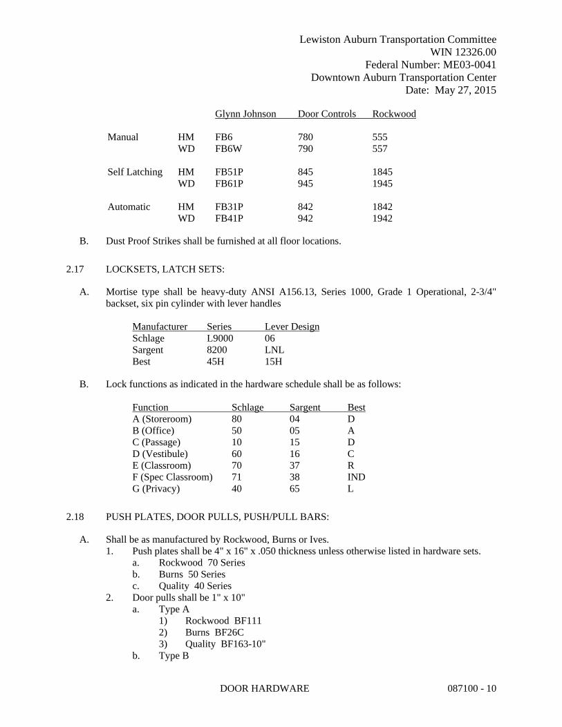
Lewiston Auburn Transportation CommitteeWIN 12326.00
Federal Number: ME03-0041Downtown Auburn Transportation Center
Date: May 27, 2015
DOOR HARDWARE 087100 - 10
Glynn Johnson Door Controls Rockwood
Manual HM FB6 780 555WD FB6W 790 557
Self Latching HM FB51P 845 1845WD FB61P 945 1945
Automatic HM FB31P 842 1842WD FB41P 942 1942
B. Dust Proof Strikes shall be furnished at all floor locations.
2.17 LOCKSETS, LATCH SETS:
A. Mortise type shall be heavy-duty ANSI A156.13, Series 1000, Grade 1 Operational, 2-3/4" backset, six pin cylinder with lever handles
Manufacturer Series Lever DesignSchlage L9000 06Sargent 8200 LNLBest 45H 15H
B. Lock functions as indicated in the hardware schedule shall be as follows:
Function Schlage Sargent BestA (Storeroom) 80 04 DB (Office) 50 05 AC (Passage) 10 15 DD (Vestibule) 60 16 CE (Classroom) 70 37 RF (Spec Classroom) 71 38 INDG (Privacy) 40 65 L
2.18 PUSH PLATES, DOOR PULLS, PUSH/PULL BARS:
A. Shall be as manufactured by Rockwood, Burns or Ives.1. Push plates shall be 4" x 16" x .050 thickness unless otherwise listed in hardware sets.
a. Rockwood 70 Seriesb. Burns 50 Seriesc. Quality 40 Series
2. Door pulls shall be 1" x 10"a. Type A
1) Rockwood BF1112) Burns BF26C3) Quality BF163-10"
b. Type B

Lewiston Auburn Transportation CommitteeWIN 12326.00
Federal Number: ME03-0041Downtown Auburn Transportation Center
Date: May 27, 2015
DOOR HARDWARE 087100 - 11
1) Rockwood 1572) Burns 39C3) Quality 521
2.19 KICK PLATES, ARMOR PLATES, MOP PLATES:
A. Kick plates shall be 8 in. high. Armor plates shall be 34 in. high. Mop plates shall be 4 in. high. All plates shall be 2 in. less the width of door. Plates shall be .050 thickness, bevel 4 edges, screws shall be oval head counter-sunk.
2.20 STOPS:
A. Shall be furnished at all doors. Wherever an opened door or any item of hardware thereon strikes a wall, at 90 degrees provide wall bumpers, unless otherwise indicated in hardware sets.
B. Where wall bumpers cannot be effectively used, a floor stop shall be furnished and installed.
C. Provide roller bumpers for each door where two doors interfere with each other in swinging.
Manufacturer Wall Bumpers Floor Stops Roller BumpersRockwood 409 440,442 456Ives 407 1/2 436B, 438B 470 SeriesGlynn Johnson WB 50XT FB13, FB14 RB-3
D. Where overhead stops are listed they shall be the surface mounted type as follows:
Manufacturer SeriesGlynn-Johnson GJ450Sargent 1540ABH 4400
2.21 THRESHOLDS, WEATHERSTRIP, SEAL:
A. Thresholds shall be as detailed and furnished on all doors where shown on drawings. Thresholds shall be aluminum unless otherwise indicated. Set thresholds for exterior and acoustical doors in full bed of sealant complying with requirements specified in Division 7 Section "Joint Sealants".
B. Weatherstripping shall be furnished on all exterior doors unless otherwise indicated.
Product NGP PemkoThreshold as detailedBrush Seal A626A 18041Auto. Door Bottom 420 2548Door Sweep 101AV 345Set Astragals 140 x 140P 351Astragal 139SP 357Rain Drip 16AD 346C

Lewiston Auburn Transportation CommitteeWIN 12326.00
Federal Number: ME03-0041Downtown Auburn Transportation Center
Date: May 27, 2015
DOOR HARDWARE 087100 - 12
Gasketing 600A 18062
2.22 SILENCERS:
A. Provide silencers on all metal and wood frames. Silencers shall be Ives 20/21, Glynn Johnson 64/65 or Rockwood 608/609.
2.23 RECESSED DOOR CONTACT
A. Provide recessed high security concealed magnetic contacts similar to Sentrol Inc. or equal1. 1275 Series Recessed 3/8” diameter Wing Fit with Wire Leads, Concealed Magnetic
Contacts.
2.24 POWER SUPPLY
A. 6 Amp Class 2 Power Supply:1. Product: Model 636RF 6 Amp Power Supply as manufactured by SDC Security Door
Controls or equal2. (1) 6A output and (3) 2A outputs.3. Field selectable 12/24 VDC.4. Emergency release input with field selectable manual reset.5. Low battery disconnect.6. Input, output and battery status.7. Battery charger (Batteries not included)8. Large cabinet: 16 inches W by 14 inches H by 6 inches D.9. Provide FB5 or Door control modules as required.10. Provide battery backup – One, two, four, six pieces of RB12V7
PART 3 - EXECUTION
3.1 INSPECTION
A. It shall be the general contractor’s responsibility to inspect all door openings and doors to determine that each door and door frame has been properly prepared for the required hardware. If errors in dimensions or preparation are encountered, they are to be corrected by the responsible parties prior to the installation of hardware.
3.2 PREPARATION
A. All doors and frames, requiring field preparation for finish hardware, shall be carefully mortised, drilled for pilot holes, or tapped for machine screws for all items of finish hardware in accordance with the manufacturer’s templates and instructions.

Lewiston Auburn Transportation CommitteeWIN 12326.00
Federal Number: ME03-0041Downtown Auburn Transportation Center
Date: May 27, 2015
DOOR HARDWARE 087100 - 13
3.3 INSTALLATION/ADJUSTMENT/LOCATION
A. All materials shall be installed in a workmanlike manner following the manufacturer's recommended instructions.
B. Exit Devices shall be carefully installed so as to permit friction free operation of crossbar, touch bar, lever. Latching mechanism shall also operate freely without friction or binding.
C. Door Closers shall be installed in accordance with the manufacturer's instructions. Each door closer shall be carefully installed, on each door, at the degree of opening indicated on the hardware schedule. Arm position shall be as shown on the instruction sheets and required by the finish hardware schedule.
D. The adjustments for all door closers shall be the installer’s responsibility and these adjustments shall be made at the time of installation of the door closer. The closing speed and the latching speed valves, shall be adjusted individually to provide a smooth, continuous closing action without slamming. The delayed action feature or back check valve shall also be adjusted so as to permit the correct delayed action cycle or hydraulic back check cushioning of the door in the opening cycle. All valves must be properly adjusted at the time of installation. Each door closer has adjustable spring power capable of being adjusted, in the field, from size 1 thru 6. It shall be the installers responsibility to adjust the spring power for each door closer in exact accordance with the spring power adjustment chart illustrated in the door closer installation sheet packed with each door closer.
E. Installation of all other hardware, including locksets, push-pull latches, overhead holders, door stops, plates and other items, shall be carefully coordinated with the hardware schedule and the manufacturer's instruction sheets.
F. Locations for finish hardware shall be in accordance with dimensions listed in the pamphlet "Recommended locations for Builders' Hardware" published by the Door and Hardware Institute.
3.4 PROTECTION
A. All exposed portions of finish hardware shall be carefully protected, by use of cloth, adhesive backed paper or other materials, immediately after installation of the hardware item on the door. The finish shall remain protected until completion of the project. Prior to acceptance of the project by the Architect and owner, the general contractor shall remove the protective material exposing the finish hardware.
3.5 CLEANING
A. It shall be the responsibility of the general contractor to clean all items of finish hardware and to remove any remaining pieces of protective materials and labels.

Lewiston Auburn Transportation CommitteeWIN 12326.00
Federal Number: ME03-0041Downtown Auburn Transportation Center
Date: May 27, 2015
DOOR HARDWARE 087100 - 14
3.6 INSTRUCTIONS AND TOOLS
A. It shall be the responsibility of the general contractor to provide installation and repair manuals and adjusting tools, wrenches, etc. for the following operating products:1. Locksets (all types)2. Exit Devices (all types)3. Door Closers
B. These items are included with the factory supplied material – General Contractor to collect these items and give to owner.
3.7 HARDWARE SETS
Each Hardware Set listed below represents the complete hardware requirements for one opening (single door or pair of doors). Furnish the quantities required for each set for the work.
HW1 - DOORS 1A and 2A
EACH LEAF SHALL HAVE: HINGES, EXIT DEVICE, ENTRY FUNCTION LOCKSET, CYLINDER, ELECTRIC DOOR OPERATOR, KICK PLATE, THRESHOLD, PERIMETER WEATHERSTRIP, ADA PUSH PAD OPERATOR W/ INTERFACE, AND POWER SUPPLY. (BALANCE OF HARDWARE BY ALUMINUM DOOR SUPPLIER)
HW2 - DOORS 1B and 2B
EACH LEAF SHALL HAVE: HINGES, EXIT DEVICE, ENTRY FUNCTION LOCKSET, CYLINDER, ELECTRIC DOOR OPERATOR, KICK PLATE, PERIMETER WEATHERSTRIP, ADA PUSH PAD OPERATOR W/ INTERFACE, AND POWER SUPPLY. (BALANCE OF HARDWARE BY ALUMINUM DOOR SUPPLIER)
HW4 - DOORS 7 and 8
EACH LEAF SHALL HAVE: HINGES, PRIVACY SET, DOOR STOP, SILENCERS
HW 5 - DOORS 5 and 9
EACH LEAF SHALL HAVE: HINGES, PASSAGE SET, CLOSER, DOOR STOP, SILENCERS, KICK=PLATE
HW6 – DOOR 6
EACH LEAF SHALL HAVE: HINGES, STOREROOM SET, DOOR STOP, SILENCERS, KICK-PLATE
END OF SECTION 087100

Lewiston Auburn Transportation CommitteeWIN 12326.00
Federal Number: ME03-0041Downtown Auburn Transportation Center
Date: May 27, 2015
GLAZING 088000 - 1
SPECIAL PROVISIONSECTION 088000
GLAZING
PART 1 - GENERAL
1.1 RELATED DOCUMENTS
A. Drawings and general provisions of the Contract, including General and Supplementary Conditions and Division 01 Specification Sections, apply to this Section.
1.2 SUMMARY
A. Section includes glazing for the following products and applications, including those specified in other Sections where glazing requirements are specified by reference to this Section:1. Insulated Glazing - Doors, storefront and storefront entrances
B. Related Sections:1. Division 08 Section "Hollow Metal Doors and Frames” & "Wood Doors" for factory
glazing of wood doors with glazed openings.
1.3 DEFINITIONS
A. Glass Thicknesses: Indicated by thickness designations in millimeters according to ASTM C 1036.
B. Interspace: Space between lites of an insulating-glass unit.
1.4 PERFORMANCE REQUIREMENTS
A. General: Installed glazing systems shall withstand normal thermal movement and wind and impact loads (where applicable) without failure, including loss or glass breakage attributable to the following: defective manufacture, fabrication, or installation; failure of sealants or gaskets to remain watertight and airtight; deterioration of glazing materials; or other defects in construction.
B. Thermal Movements: Allow for thermal movements from ambient and surface temperature changes acting on glass framing members and glazing components.1. Temperature Change: 120 deg F, ambient; 180 deg F, material surfaces.
1.5 ACTION SUBMITTALS
A. Product Data: For each glass product and glazing material indicated.
Lewiston Auburn Transportation CommitteeWIN 12326.00
Federal Number: ME03-0041Downtown Auburn Transportation Center
Date: May 27, 2015
GLAZING 088000 - 2
B. Glazing Schedule: List glass types and thicknesses for each size opening and location. Use same designations indicated on Drawings.
1.6 INFORMATIONAL SUBMITTALS
A. Product Certificates: For glass and glazing products, from manufacturer.
B. Warranties: Sample of special warranties.
1.7 QUALITY ASSURANCE
A. Source Limitations for Glass: Obtain coated float glass, laminated glass, fire-rated glazing, andinsulating glass from single source from single manufacturer for each glass type.
B. Source Limitations for Glazing Accessories: Obtain from single source from single manufacturer for each product and installation method.
C. Glazing Publications: Comply with published recommendations of glass product manufacturers and organizations below, unless more stringent requirements are indicated. Refer to these publications for glazing terms not otherwise defined in this Section or in referenced standards.1. GANA Publications: GANA's "Laminated Glazing Reference Manual" and GANA's
"Glazing Manual."2. IGMA Publication for Insulating Glass: SIGMA TM-3000, "North American Glazing
Guidelines for Sealed Insulating Glass Units for Commercial and Residential Use."
D. Safety Glazing Labeling: Where safety glazing labeling is indicated, permanently mark glazing with certification label of the SGCC. Label shall indicate manufacturer's name, type of glass, thickness, and safety glazing standard with which glass complies.
E. Fire-Protection-Rated Glazing Labeling: Permanently mark fire-protection-rated glazing with certification label of a testing agency acceptable to authorities having jurisdiction. Label shall indicate manufacturer's name, test standard, whether glazing is for use in fire doors or other openings, whether or not glazing passes hose-stream test, whether or not glazing has a temperature rise rating of 450 deg F, and the fire-resistance rating in minutes.
F. Insulating-Glass Certification Program: Permanently marked either on spacers or on at least one component lite of units with appropriate certification label of IGCC.
1.8 DELIVERY, STORAGE, AND HANDLING
A. Protect glazing materials according to manufacturer's written instructions. Prevent damage to glass and glazing materials from condensation, temperature changes, direct exposure to sun, or other causes.1. Protect fire-resistive glazing from ultraviolet light.

Lewiston Auburn Transportation CommitteeWIN 12326.00
Federal Number: ME03-0041Downtown Auburn Transportation Center
Date: May 27, 2015
GLAZING 088000 - 3
1.9 PROJECT CONDITIONS
A. Environmental Limitations: Do not proceed with glazing when ambient and substrate temperature conditions are outside limits permitted by glazing material manufacturers and when glazing channel substrates are wet from rain, frost, condensation, or other causes.1. Do not install glazing sealants when ambient and substrate temperature conditions are
outside limits permitted by sealant manufacturer or below 40 deg F.
1.10 WARRANTY
A. Manufacturer's Special Warranty for Coated-Glass Products: Manufacturer's standard form in which coated-glass manufacturer agrees to replace coated-glass units that deteriorate within specified warranty period. Deterioration of coated glass is defined as defects developed from normal use that are not attributed to glass breakage or to maintaining and cleaning coated glass contrary to manufacturer's written instructions. Defects include peeling, cracking, and other indications of deterioration in coating.1. Warranty Period: 10 years from date of Substantial Completion.
B. Manufacturer's Special Warranty on Laminated Glass: Manufacturer's standard form in which laminated-glass manufacturer agrees to replace laminated-glass units that deteriorate within specified warranty period. Deterioration of laminated glass is defined as defects developed from normal use that are not attributed to glass breakage or to maintaining and cleaning laminated glass contrary to manufacturer's written instructions. Defects include edge separation, delamination materially obstructing vision through glass, and blemishes exceeding those allowed by referenced laminated-glass standard.1. Warranty Period: Five years from date of Substantial Completion.
C. Manufacturer's Special Warranty on Insulating Glass: Manufacturer's standard form in which insulating-glass manufacturer agrees to replace insulating-glass units that deteriorate within specified warranty period. Deterioration of insulating glass is defined as failure of hermetic seal under normal use that is not attributed to glass breakage or to maintaining and cleaning insulating glass contrary to manufacturer's written instructions. Evidence of failure is the obstruction of vision by dust, moisture, or film on interior surfaces of glass.1. Warranty Period: 10 years from date of Substantial Completion.
D. Manufacturer's Special Warranty on Fire-Rated Glass: Manufacturer's standard form in which fire rated glass manufacturer agrees to replace fire rated glass units that deteriorate within specified warranty period. Deterioration of fire rated glass is defined as failure defects developed from normal use that are not attributed to glass breakage or to maintaining and cleaning fire rated glass contrary to manufacturer's written instructions. Defects include obstruction of glass area, delamination, or edge separation and/or changes in properties of the interlayer.1. Warranty Period: Five years from date of Substantial Completion.
E. Manufacturer's Special Warranty for Glass-Clad Polycarbonate: Manufacturer agrees to replace glass-clad polycarbonate that deteriorates within specified warranty period. Deterioration of glass-clad polycarbonate is defined as defects developed from normal use that are not attributed

Lewiston Auburn Transportation CommitteeWIN 12326.00
Federal Number: ME03-0041Downtown Auburn Transportation Center
Date: May 27, 2015
GLAZING 088000 - 4
to glass breakage or to maintaining and cleaning glass-clad polycarbonate contrary to manufacturer's written instructions. Defects include edge separation, delamination materially obstructing vision through glazing, blemishes exceeding those allowed by referenced glass-clad polycarbonate standard, yellowing, and loss of light transmission.1. Warranty Period: Five years from date of Substantial Completion.
PART 2 - PRODUCTS
2.1 GLASS PRODUCTS, GENERAL
A. Thickness: Where glass thickness is indicated, it is a minimum. Provide glass lites in thicknesses as needed to comply with requirements indicated.1. Minimum Glass Thickness for Exterior Lites: Not less than 6.0 mm.
B. Strength: Where float glass is indicated, provide annealed float glass. Where fully tempered glass or safety glazing is indicated or required by code, provide Kind FT heat-treated float glass.
2.2 GLASS PRODUCTS
A. Float Glass: ASTM C 1036, Type I, Quality-Q3, Class I (clear) unless otherwise indicated.
B. Safety Glass (Fully Tempered): ASTM C 1048; Kind FT (fully tempered), Condition A (uncoated), Type I (transparent flat glass); Class 1(clear); Quality q3 (glazing select); conforming to ANZI A97.1If heat soaking of fully tempered glass is needed, insert requirements here.
2.3 INSULATING GLASS
A. Insulating-Glass Units: Factory-assembled units consisting of sealed lites of glass separated by a dehydrated interspace, qualified according to ASTM E 2190, and complying with other requirements specified.1. Sealing System: Dual seal, with manufacturer's standard primary and secondary.2. Spacer: Manufacturer's standard warm edge spacer material and construction.3. Desiccant: Molecular sieve or silica gel, or blend of both.
B. Glass: Comply with applicable requirements in "Glass Products" Article as indicated by designations in "Insulating-Glass Types" Article.
C. Low-E, Clear, Insulated Glass Units:1. Overall Unit Thickness:
a. For Exterior Locations Other Than Doors: Inner and outer panes of 6.0 mm glass; total unit thickness of 1 inch minimum.
b. For Exterior Doors: Inner and outer panes of 3/16 clear glass; total unit thickness of 5/8 inch minimum.
2. Outdoor Lite: Class 1 (clear) float glass, except as noted.

Lewiston Auburn Transportation CommitteeWIN 12326.00
Federal Number: ME03-0041Downtown Auburn Transportation Center
Date: May 27, 2015
GLAZING 088000 - 5
a. Kind FT (fully tempered) where indicated or required by code.3. Interspace Content: Argon.4. Indoor Lite: Class 1 (clear) float glass, except as noted.
a. Kind FT (fully tempered) where indicated or required by code.5. Low-E Coating: Sputtered on second surface.6. Visible Light Transmittance: 65 percent minimum.7. Winter Nighttime U-Factor: 0.24 maximum.8. Shading Coefficient: 0.27 maximum.9. Solar Heat Gain Coefficient: 0.27 maximum.10. Provide safety glazing labeling on fully tempered glass.
2.4 GLAZING GASKETS
A. Dense Compression Gaskets: Molded or extruded gaskets of profile and hardness required to maintain watertight seal, made from one of the following:1. EPDM complying with ASTM C 864.2. Silicone complying with ASTM C 1115.3. Thermoplastic polyolefin rubber complying with ASTM C 1115.
2.5 GLAZING SEALANTS
A. General:1. Compatibility: Provide glazing sealants that are compatible with one another and with
other materials they will contact, including glass products, seals of insulating-glass units, and glazing channel substrates, under conditions of service and application, as demonstrated by sealant manufacturer based on testing and field experience.
2. Suitability: Comply with sealant and glass manufacturers' written instructions for selecting glazing sealants suitable for applications indicated and for conditions existing at time of installation.
3. Sealants used inside the weatherproofing system shall comply with the testing and product requirements of the California Department of Health Services' "Standard Practice for the Testing of Volatile Organic Emissions from Various Sources Using Small-Scale Environmental Chambers."
4. Colors of Exposed Glazing Sealants: As selected by Architect from manufacturer's full range.
B. Glazing Sealant: Neutral-curing silicone glazing sealant complying with ASTM C 920, Type S, Grade NS, Class 50, Use NT.1. Products: Subject to compliance with requirements, provide one of the following:
a. Dow Corning Corporation; 791 or 795.b. GE Advanced Materials - Silicones; SilPruf NB SCS9000 or
UltraPruf II SCS2900.c. Pecora Corporation; 895.d. Tremco Incorporated; Spectrem 2 or Spectrem 3.
Lewiston Auburn Transportation CommitteeWIN 12326.00
Federal Number: ME03-0041Downtown Auburn Transportation Center
Date: May 27, 2015
GLAZING 088000 - 6
2.6 GLAZING TAPES
A. Back-Bedding Mastic Glazing Tapes: Preformed, butyl-based, 100 percent solids elastomeric tape; nonstaining and nonmigrating in contact with nonporous surfaces; with or without spacer rod as recommended in writing by tape and glass manufacturers for application indicated; and complying with ASTM C 1281 and AAMA 800 for products indicated below:1. AAMA 806.3 tape, for glazing applications in which tape is subject to continuous
pressure.2. AAMA 807.3 tape, for glazing applications in which tape is not subject to continuous
pressure.
B. Expanded Cellular Glazing Tapes: Closed-cell, PVC foam tapes; factory coated with adhesive on both surfaces; and complying with AAMA 800 for the following types:1. AAMA 810.1, Type 2, for glazing applications in which tape is used in combination with
a full bead of liquid sealant.
2.7 MISCELLANEOUS GLAZING MATERIALS
A. General: Provide products of material, size, and shape complying with referenced glazing standard, requirements of manufacturers of glass and other glazing materials for application indicated, and with a proven record of compatibility with surfaces contacted in installation.
B. Cleaners, Primers, and Sealers: Types recommended by sealant or gasket manufacturer.
C. Setting Blocks: Elastomeric material with a Shore, Type A durometer hardness of 85, plus or minus 5.
D. Spacers: Elastomeric blocks or continuous extrusions of hardness required by glass manufacturer to maintain glass lites in place for installation indicated.
E. Edge Blocks: Elastomeric material of hardness needed to limit glass lateral movement (side walking).
F. Cylindrical Glazing Sealant Backing: ASTM C 1330, Type O (open-cell material), of size and density to control glazing sealant depth and otherwise produce optimum glazing sealant performance.
G. Perimeter Insulation for Fire-Resistive Glazing: Product that is approved by testing agency that listed and labeled fire-resistant glazing product with which it is used for application and fire-protection rating indicated.
2.8 FABRICATION OF GLAZING UNITS
A. Fabricate glazing units in sizes required to fit openings indicated for Project, with edge and face clearances, edge and surface conditions, and bite complying with written instructions of productmanufacturer and referenced glazing publications, to comply with system performance requirements.

Lewiston Auburn Transportation CommitteeWIN 12326.00
Federal Number: ME03-0041Downtown Auburn Transportation Center
Date: May 27, 2015
GLAZING 088000 - 7
B. Grind smooth and polish exposed glass edges and corners.
PART 3 - EXECUTION
3.1 EXAMINATION
A. Examine framing, glazing channels, and stops, with Installer present, for compliance with the following:1. Manufacturing and installation tolerances, including those for size, squareness, and
offsets at corners.2. Presence and functioning of weep systems.3. Minimum required face and edge clearances.4. Effective sealing between joints of glass-framing members.
B. Proceed with installation only after unsatisfactory conditions have been corrected.
3.2 PREPARATION
A. Clean glazing channels and other framing members receiving glass immediately before glazing. Remove coatings not firmly bonded to substrates.
B. Examine glazing units to locate exterior and interior surfaces. Label or mark units as needed so that exterior and interior surfaces are readily identifiable. Do not use materials that will leave visible marks in the completed work.
3.3 GLAZING, GENERAL
A. Comply with combined written instructions of manufacturers of glass, sealants, gaskets, and other glazing materials, unless more stringent requirements are indicated, including those in referenced glazing publications.
B. Adjust glazing channel dimensions as required by Project conditions during installation to provide necessary bite on glass, minimum edge and face clearances, and adequate sealant thicknesses, with reasonable tolerances.
C. Protect glass edges from damage during handling and installation. Remove damaged glass from Project site and legally dispose of off Project site. Damaged glass is glass with edge damage or other imperfections that, when installed, could weaken glass and impair performance and appearance. Protect glass edges as follows:1. Use a rolling block in rotating glass units to prevent damage to glass corners.2. Do not impact glass with metal framing. 3. Use suction cups to shift glass units within openings. Do not raise or drift glass with a
pry bar.4. Rotate glass lites with flares or bevels on bottom horizontal edges so edges are located at
top of opening, unless otherwise indicated by manufacturer's label.

Lewiston Auburn Transportation CommitteeWIN 12326.00
Federal Number: ME03-0041Downtown Auburn Transportation Center
Date: May 27, 2015
GLAZING 088000 - 8
D. Apply primers to joint surfaces where required for adhesion of sealants.
E. Install setting blocks in sill rabbets, sized and located to comply with referenced glazing publications, unless otherwise required by glass manufacturer. Set blocks in thin course of compatible sealant suitable for heel bead.
F. Do not exceed edge pressures stipulated by glass manufacturers for installing glass lites.
G. Provide spacers for glass lites where length plus width is larger than 50 inches.1. Locate spacers directly opposite each other on both inside and outside faces of glass.
Install correct size and spacing to preserve required face clearances, unless gaskets and glazing tapes are used that have demonstrated ability to maintain required face clearances and to comply with system performance requirements.
2. Provide 1/8-inch minimum bite of spacers on glass and use thickness equal to sealant width. With glazing tape, use thickness slightly less than final compressed thickness of tape.
H. Provide edge blocking where indicated or needed to prevent glass lites from moving sideways in glazing channel, as recommended in writing by glass manufacturer and according to requirements in referenced glazing publications.
I. Set glass lites in each series with uniform pattern, draw, bow, and similar characteristics.
J. Set glass lites with proper orientation so that coatings face exterior or interior as specified.
3.4 TAPE GLAZING
A. Position tapes on fixed stops so that, when compressed by glass, their exposed edges are flush with or protrude slightly above sightline of stops.
B. Install tapes continuously, but not necessarily in one continuous length. Do not stretch tapes to make them fit opening.
C. Cover vertical framing joints by applying tapes to heads and sills first and then to jambs. Cover horizontal framing joints by applying tapes to jambs and then to heads and sills.
D. Place joints in tapes at corners of opening with adjoining lengths butted together, not lapped. Seal joints in tapes with compatible sealant approved by tape manufacturer.
E. Do not remove release paper from tape until right before each glazing unit is installed.
F. Apply heel bead of elastomeric sealant.
G. Center glass lites in openings on setting blocks and press firmly against tape by inserting dense compression gaskets formed and installed to lock in place against faces of removable stops. Start gasket applications at corners and work toward centers of openings.

Lewiston Auburn Transportation CommitteeWIN 12326.00
Federal Number: ME03-0041Downtown Auburn Transportation Center
Date: May 27, 2015
GLAZING 088000 - 9
H. Apply cap bead of elastomeric sealant over exposed edge of tape.
3.5 GASKET GLAZING (DRY)
A. Cut compression gaskets to lengths recommended by gasket manufacturer to fit openings exactly, with allowance for stretch during installation.
B. Insert soft compression gasket between glass and frame or fixed stop so it is securely in place with joints miter cut and bonded together at corners.
C. Installation with Drive-in Wedge Gaskets: Center glass lites in openings on setting blocks and press firmly against soft compression gasket by inserting dense compression gaskets formed and installed to lock in place against faces of removable stops. Start gasket applications at corners and work toward centers of openings. Compress gaskets to produce a weathertight seal without developing bending stresses in glass. Seal gasket joints with sealant recommended by gasket manufacturer.
D. Installation with Pressure-Glazing Stops: Center glass lites in openings on setting blocks and press firmly against soft compression gasket. Install dense compression gaskets and pressure-glazing stops, applying pressure uniformly to compression gaskets. Compress gaskets to produce a weathertight seal without developing bending stresses in glass. Seal gasket joints with sealant recommended by gasket manufacturer.
E. Install gaskets so they protrude past face of glazing stops.
3.6 SEALANT GLAZING (WET)
A. Install continuous spacers, or spacers combined with cylindrical sealant backing, between glass lites and glazing stops to maintain glass face clearances and to prevent sealant from extruding into glass channel and blocking weep systems until sealants cure. Secure spacers or spacers and backings in place and in position to control depth of installed sealant relative to edge clearance for optimum sealant performance.
B. Force sealants into glazing channels to eliminate voids and to ensure complete wetting or bond of sealant to glass and channel surfaces.
C. Tool exposed surfaces of sealants to provide a substantial wash away from glass.
3.7 CLEANING AND PROTECTION
A. Protect exterior glass from damage immediately after installation by attaching crossed streamers to framing held away from glass. Do not apply markers to glass surface. Remove nonpermanent labels and clean surfaces.

Lewiston Auburn Transportation CommitteeWIN 12326.00
Federal Number: ME03-0041Downtown Auburn Transportation Center
Date: May 27, 2015
GLAZING 088000 - 10
B. Protect glass from contact with contaminating substances resulting from construction operations. If, despite such protection, contaminating substances do come into contact with glass, remove substances immediately as recommended in writing by glass manufacturer.
C. Examine glass surfaces adjacent to or below exterior concrete and other masonry surfaces at frequent intervals during construction, but not less than once a month, for buildup of dirt, scum, alkaline deposits, or stains; remove as recommended in writing by glass manufacturer.
D. Remove and replace glass that is broken, chipped, cracked, or abraded or that is damaged from natural causes, accidents, and vandalism, during construction period.
E. Wash glass on both exposed surfaces in each area of Project not more than four days before date scheduled for inspections that establish date of Substantial Completion. Wash glass as recommended in writing by glass manufacturer.
END OF SECTION 088000

Lewiston Auburn Transportation Committee WIN 12326.00
Federal Number: ME03-0041 Downtown Auburn Transportation Center
Date: May 27, 2015
GYPSUM BOARD ASSEMBLIES 092950 - 1
SPECIAL PROVISION SECTION 092950
GYPSUM BOARD ASSEMBLIES
PART 1 - GENERAL
1.1 RELATED DOCUMENTS
A. Drawings and general provisions of the Contract, including General and Supplementary Conditions and Division 01 Specification Sections, apply to this Section.
1.2 SUMMARY
A. This Section includes the following: 1. Interior gypsum wallboard. 2. Non-load-bearing steel framing. 3. Exterior wall sheathing 4. Exterior soffits 5. Interior suspension systems.
B. Related Sections include the following: 1. Division 05 Section "Cold-Formed Metal Framing" for non-load-bearing steel framing
and glass-mat gypsum sheathing. 2. Division 06 Section "Rough Carpentry" for concealed wood blocking in gypsum board
assembly walls; wood framing and furring, and metal Z- and J-furring supporting plywood wall sheathing.
3. Division 07 Section "Building Insulation" for thermal insulation and vapor retarders installed in gypsum board assemblies.
4. Division 07 Section "Joint Sealants" for sealants not covered by work of this Section. 5. Division 09 Section "Painting" for coordination/inspection requirements with painting
contractor and primers applied to gypsum board surfaces.
1.3 DEFINITIONS
A. Gypsum Board Terminology: Refer to ASTM C 11 and GA-505 for definitions of terms for gypsum board assemblies not defined in this Section or in other referenced standards.
1.4 SUBMITTALS
A. General: Submit in accordance with Division 01 Section "Submittal Procedures."
B. Product Data: For each type of product indicated.

Lewiston Auburn Transportation Committee WIN 12326.00
Federal Number: ME03-0041 Downtown Auburn Transportation Center
Date: May 27, 2015
GYPSUM BOARD ASSEMBLIES 092950 - 2
C. Shop Drawings: Show locations, fabrication, and installation of control and expansion joints including plans, elevations, sections, details of components, and attachments to other units of Work. 1. Submit marked up floor plans with location of all control joints in gypsum board walls
and ceilings.
1.5 QUALITY ASSURANCE
A. Fire-Test-Response Characteristics: For gypsum board assemblies with fire-resistance ratings, provide materials and construction identical to those tested in assembly indicated according to ASTM E 119 by an independent testing and inspecting agency acceptable to authorities having jurisdiction. 1. Fire-Resistance-Rated Assemblies: Indicated by design designations from UL's "Fire
Resistance Directory," GA-600, "Fire Resistance Design Manual," or in the listing of another testing and inspecting agency acceptable to authorities having jurisdiction.
2. Deflection Firestop Track: Top runner indicated in fire-resistance-rated assemblies shall be labeled and listed by UL, Warnock Hersey, or another testing and inspecting agency acceptable to authorities having jurisdiction.
B. Sound Transmission Characteristics: For gypsum board assemblies with STC ratings, provide materials and construction identical to those tested in assembly indicated according to ASTM E 90 and classified according to ASTM E 413 by a qualified independent testing agency. 1. STC-Rated Assemblies: Indicated by design designations from GA-600, "Fire Resistance
Design Manual" or other approved qualified independent testing agency.
C. Source Limitations for Steel Framing: Obtain steel framing members for gypsum board assemblies from a single source from a single manufacturer.
D. Source Limitations for Panel Products: Obtain each type of gypsum board and other panel products from a single source from a single manufacturer.
E. Source Limitations for Finishing Materials: Obtain finishing materials from either a manufacturer supplying gypsum board and other panel products or from a manufacturer acceptable to gypsum board manufacturer.
F. Gypsum Board Finish Mockups: Before finishing gypsum board assemblies, install mockups using room designated by Architect to demonstrate aesthetic effects and qualities of materials and execution. 1. Install mockups for surfaces indicated to receive nontextured paint finishes. 2. Simulate finished lighting conditions for review of mockups. 3. Mockup will be painted under Division 09 Section "Painting" to provide finished
condition for viewing. 4. Approved mockups may become part of the completed Work if undisturbed at time of
Substantial Completion.

Lewiston Auburn Transportation Committee WIN 12326.00
Federal Number: ME03-0041 Downtown Auburn Transportation Center
Date: May 27, 2015
GYPSUM BOARD ASSEMBLIES 092950 - 3
1.6 DELIVERY, STORAGE, AND HANDLING
A. Deliver materials in original packages, containers, or bundles bearing brand name and identification of manufacturer or supplier.
B. Store materials inside under cover and keep them dry and protected against damage from weather, direct sunlight, surface contamination, corrosion, construction traffic, and other causes.
C. Stack gypsum panels flat on leveled supports off floor or slab to prevent sagging.
D. Gypsum Sheathing: Stack panels flat with spacers beneath and between each bundle to provide air circulation. Protect sheathing from weather by covering with waterproof sheeting, securely anchored. Provide for air circulation around stacks and under coverings.
1.7 PROJECT CONDITIONS
A. Environmental Limitations: Establish and maintain environmental conditions for applying and finishing gypsum board to comply with ASTM C 840 requirements or gypsum board manufacturer's written recommendations, whichever are more stringent.
B. Do not install interior products until installation areas are enclosed and conditioned.
C. Do not install panels that are wet, those that are moisture damaged, and those that are mold damaged. 1. Indications that panels are wet or moisture damaged include, but are not limited to,
discoloration, sagging, or irregular shape. 2. Indications that panels are mold damaged include, but are not limited to, fuzzy or
splotchy surface contamination and discoloration.
D. Room Temperatures: For nonadhesive attachment of gypsum board to framing, maintain not less than 40 deg F. Do not exceed 95 deg F when using temporary heat sources.
E. Ventilation: Ventilate building spaces as required to dry joint treatment materials. Avoid drafts during hot, dry weather to prevent finishing materials from drying too rapidly.
1.8 COORDINATION
A. Coordinate installation of fasteners into overhead floor deck to insure radiant heat tubing is not damaged.
B. Coordination attachment of runner tracks with radiant heat installation to insure framing fasteners do not penetrate tubing.

Lewiston Auburn Transportation Committee WIN 12326.00
Federal Number: ME03-0041 Downtown Auburn Transportation Center
Date: May 27, 2015
GYPSUM BOARD ASSEMBLIES 092950 - 4
PART 2 - PRODUCTS
2.1 MANUFACTURERS
A. In other Part 2 articles where titles below introduce lists, the following requirements apply for product selection: 1. Manufacturers: Subject to compliance with requirements, provide products by the
manufacturers specified. 2. Products: Subject to compliance with requirements, provide one of the products
specified.
2.2 NON-LOAD-BEARING STEEL FRAMING, GENERAL
A. Framing Members, General: Comply with ASTM C 754 for conditions indicated. 1. Steel Sheet Components: Comply with ASTM C 645 requirements for metal, unless
otherwise indicated. 2. Protective Coating: ASTM A 653, G40, hot-dip galvanized, unless otherwise indicated.
2.3 STEEL SUSPENDED CEILING AND SOFFIT FRAMING
A. Manufacturers: 1. Clark Dietrich Building Systems. 2. MarinoWare; Division of Ware Ind. 3. Super Stud Building Products, Inc.
B. Tie Wire: ASTM A 641/A 641M, Class 1 zinc coating, soft temper, not less than 0.0625-inch- diameter (8-gage) wire, or double strand of not less than 0.099-inch- diameter (12-gage) wire.
C. Hanger Attachments to Concrete: As follows: 1. Powder-Actuated Fasteners: Suitable for application indicated, fabricated from
corrosion-resistant materials, with clips or other devices for attaching hangers of type indicated, and capable of sustaining, without failure, a load equal to 10 times that imposed by construction as determined by testing according to ASTM E 1190 by a qualified independent testing agency.
D. Hangers: As follows: 1. Wire Hangers: ASTM A 641/A 641M, Class 1 zinc coating, soft temper, 0.162-inch
diameter (8-gage).
E. Carrying Channels: Cold-rolled, commercial-steel sheet with a base metal thickness of 0.0538 inch, a minimum 1/2-inch- wide flange, with ASTM A 653/A 653M, G40, hot-dip galvanized zinc coating. 1. Depth: 2 inches, unless indicated otherwise.
F. Furring Channels (Furring Members): Commercial-steel sheet with ASTM A 653/A 653M, G40, hot-dip galvanized zinc coating. 1. Hat-Shaped, Rigid Furring Channels: ASTM C 645, 7/8 inch deep; where indicated.
a. Minimum Base Metal Thickness: 0.0312 inch (22 gage).
Lewiston Auburn Transportation Committee WIN 12326.00
Federal Number: ME03-0041 Downtown Auburn Transportation Center
Date: May 27, 2015
GYPSUM BOARD ASSEMBLIES 092950 - 5
G. Hand-Formable Arch Tracks: Factory fabricated runner track, providing smooth, non-segmented continuous one-piece shape; 0.0329 inch thick, 20 gage; size as indicated. 1. Products: Provide the following products by Radius Track Corporation, (888) 872-3487:
a. Hand-Formable Ready-Arch.
H. Grid Suspension System for Interior Ceilings: ASTM C 645, direct-hung system composed of main beams and cross-furring members that interlock, heavy-duty. 1. Products:
a. Armstrong World Industries, Inc.; Drywall Grid Systems. b. Chicago Metallic Corporation; 640-C Drywall Furring System. c. USG Interiors, Inc.; Drywall Suspension System. d. Provide comparable system where fire-rated ceilings are indicated.
2.4 STEEL PARTITION AND SOFFIT FRAMING
A. Products: 1. Clark Dietrich Building Systems; ProSTUD. 2. MarinoWare; Division of Ware Ind.; ViperStud. 3. Super Stud Building Products, Inc.; The Edge Framing.
B. Steel Studs and Runners, Gauge Equivalent Drywall Framing: ASTM C 645. 1. Minimum Base Metal Thickness: 0.0158 inch (25 gage equivalent studs) minimum,
unless otherwise indicated. a. Provide studs with 0.0200 inch (20 gage equivalent studs) minimum thickness at
the following locations: 1) For 6 inch and greater framing. 2) For framing over 12 feet high. 3) For door jamb framing. 4) At locations to receive tile backer board. 5) At locations to receive abuse-resistant board. 6) At locations receiving wall mounted equipment (shelving, casework and
cabinets, televisions, grab bars, and where directed by Architect). 7) Where indicated.
2. Depth: As indicated. 3. Maximum Allowable Deflection: Increase metal thickness where required to meet the
following: a. Maximum Allowable Deflection for Drywall Assemblies: L/240 calculated using
a 5 pound per square uniform load perpendicular to studs and based on stud properties alone.
b. Maximum Allowable Deflection for Drywall Assemblies Receiving Tile and Tile Backing Panels: L/360 calculated using a 5 pound per square uniform load perpendicular to studs and based on stud properties alone.
C. Deep-Leg Deflection Track: ASTM C 645 top runner with flanges to allow for 3/4-inch deflection at floors and 1-1/2 inch at roofs.

Lewiston Auburn Transportation Committee WIN 12326.00
Federal Number: ME03-0041 Downtown Auburn Transportation Center
Date: May 27, 2015
GYPSUM BOARD ASSEMBLIES 092950 - 6
D. Firestop Deflection Track: Top runner manufactured to allow partition heads to expand and contract with movement of the structure while maintaining continuity of fire-resistance-rated assembly indicated; in thickness not less than indicated for studs and in width to accommodate depth of studs. Provide deflection track with flanges to allow for 3/4-inch deflection at floors and 1-1/2 inch at roofs. 1. Product: Fire Trak Corp.; Fire Trak attached to studs with Fire Trak Slip Clip.
E. Flat Strap and Backing Plate: Steel sheet for blocking and bracing in length and width indicated. 1. Minimum Base Metal Thickness: 0.0598 inch (16 gage), unless indicated otherwise.
F. Cold-Rolled Channel Bridging: 0.0538-inch (16 gage) minimum bare steel thickness, with minimum 1/2-inch- wide flange. 1. Depth: 1-1/2 inches. 2. Clip Angle: 1-1/2 by 1-1/2 inch, 0.068-inch- thick, galvanized steel.
G. Hat-Shaped, Rigid Furring Channels: ASTM C 645. 1. Minimum Base Metal Thickness: 0.0312 inch (20 gage). 2. Depth: 7/8 inch, unless otherwise indicated.
H. Resilient Furring Channels: 1/2-inch- deep, steel sheet members designed to reduce sound transmission. 1. Configuration: Asymmetrical.
I. Furring Brackets: Serrated-arm type, adjustable, fabricated from corrosion-resistant steel sheet complying with ASTM C 645, 20 gauge, .0329 inch, designed for screw attachment to steel studs and steel rigid furring channels used for furring.
J. Deflection Brackets: 1. Construction: Slotted galvanized steel angle with step bushing to prevent over tightening
of fasteners. 2. Vertical Deflection: 1-1/2 inch total travel. 3. Product: VertiClip; Signature Industries, (919) 844-0789.
a. Series: SL, SDL, SLB, and SLS as required by attachment condition.
K. Fasteners for Metal Framing: Of type, material, size, corrosion resistance, holding power, and other properties required to fasten steel framing and furring members to substrates involved; complying with the recommendations of gypsum board manufacturers for applications indicated.
2.5 EXTERIOR WEATHER-RESISTANT GYPSUM SHEATHING
A. Manufacturers: 1. Glass-Mat Gypsum Sheathing Board:
a. Dens-Glass Gold; Georgia-Pacific Corporation. b. GlasRoc Sheathing; CertainTeed Corporation. c. Expended Exposure Sheathing e²xp; National Gypsum Company.

Lewiston Auburn Transportation Committee WIN 12326.00
Federal Number: ME03-0041 Downtown Auburn Transportation Center
Date: May 27, 2015
GYPSUM BOARD ASSEMBLIES 092950 - 7
B. Glass-Mat Gypsum Wall Sheathing: ASTM C 1177; moisture- and mold-resistant core and facers. 1. Type and Thickness: Type X, 5/8 inch thick. 2. Moisture- and Mold-Resistance: ASTM D3273, rating of 10. 3. Size: 48 by maximum available lengths.
C. Gypsum Sheathing Fasteners for Metal Framing: Steel drill screws, ASTM C 954, in length recommended by sheathing manufacturer for thickness of sheathing board to be attached, with organic-polymer or other corrosion-protective coating having a salt-spray resistance of more than 800 hours according to ASTM B 117.
2.6 PANELS, GENERAL
A. Size: Provide in maximum lengths and widths available that will minimize joints in each area and that correspond with support system indicated.
B. Manufacturers: Unless indicated otherwise, provide products by one of the following: 1. G-P Gypsum Corporation. 2. National Gypsum Company. 3. United States Gypsum Company.
2.7 INTERIOR GYPSUM WALLBOARD
A. General: Complying with ASTM C 36/C 36M or ASTM C 1396/C 1396M, as applicable to type of gypsum board indicated and whichever is more stringent.
B. Type X, GPDW: 1. Thickness: 5/8 inch. 2. Long Edges: Tapered. 3. Face Sheets: 100 percent post-consumer recycled content. 4. Location: All locations, except as otherwise noted.
C. Moisture- and Mold-Resistant Type, GPDW-MR: ASTM C 1396/C 1396M with moisture- and mold-resistant core and surfaces. 1. Core: 5/8 inch, Type X. 2. Long Edges: Tapered. 3. Mold-Resistance: ASTM D 3273, score of 10 as rated according to ASTM D 3274. 4. Face Sheets: 100 percent post-consumer recycled content. 5. Location: Interior face of all exterior walls; underside of metal trusses; walls and ceilings
of toilet rooms and janitor closets, except as indicated otherwise; and where indicated. 6. Products:
a. G-P Gypsum Corp.; Toughrock Mold-Guard Gypsum Board. b. National Gypsum Co.; Gold Bond Brand XP Gypsum Board. c. United States Gypsum Co.; Mold Tough Panels.

Lewiston Auburn Transportation Committee WIN 12326.00
Federal Number: ME03-0041 Downtown Auburn Transportation Center
Date: May 27, 2015
GYPSUM BOARD ASSEMBLIES 092950 - 8
D. Abuse-Resistant Gypsum Wallboard: ASTM C 1629/C 1629M, manufactured to produce greater resistance to surface indentation, through-penetration (impact resistance), and abrasion than standard, regular-type and Type X gypsum board. 1. Products:
a. G-P Gypsum Corp.; ToughRock Fireguard Abuse Guard Gypsum Board. b. National Gypsum Company; Gold Bond Hi-Abuse Wallboard. b. United States Gypsum Co.; Mold Tough AR Gypsum Panels.
2. Core: 5/8 inch, Type X. 3. Surface Abrasion Resistance and Soft Body Impact Resistance: Not less than Level 2. 4. Indentation Resistance and Hard Body Impact Resistance: Level 1 or greater. 5. Mold-Resistance: ASTM D 3273, score of 10 as rated according to ASTM D 3274. 6. Long Edges: Tapered. 7. Location: As indicated.
a. Note: Do not continue abuse-resistant behind tile wainscot; use tile backer board behind wall tile.
2.8 EXTERIOR GYPSUM PANELS FOR SOFFITS
A. Exterior Gypsum Soffit Board: ASTM C 931/C 931M and ASTM C 1396/C 1396M, weather-, sag- and warp-resistant, with manufacturer's standard edges. 1. Core: 5/8 inch, Type X. 2. Products:
a. G-P Gypsum Corp.; ToughRock Soffit Board. b. National Gypsum Co.; Gold Bond Exterior Soffit Board. c. United States Gypsum Co.; Sheetrock Exterior Gypsum Ceiling Board.
2.9 TRIM ACCESSORIES
A. Interior Metal Trim: ASTM C 1047, galvanized steel. 1. Shapes:
a. Cornerbead: 1-1/4 inch x 1-1/4 inch external corner with 1/8-inch nose bead. Use at outside corners, unless otherwise indicated.
b. LC-Bead (Casing): J-shaped casing with 1/16-inch nose bead ground, not less than 30 gage; exposed long flange receives joint compound; use at exposed panel edges.
c. Expansion (Control) Joint: One-piece control joint formed with V-shaped slot and removable strip covering slot opening.
d. Curved-Edge Cornerbead: With notched or flexible flanges; use at curved openings.
2. Accessories for Curved Edges: Corner bead formed of metal, plastic, or metal combined with plastic, with either notched or flexible flanges that are bendable to curvature radius.
B. Aluminum Trim: Extruded accessories of profiles and dimensions indicated. 1. Manufacturers:
a. Fry Reglet Corp. b. Gordon, Inc. c. MM Systems Corporation. d. Pittcon Industries.

Lewiston Auburn Transportation Committee WIN 12326.00
Federal Number: ME03-0041 Downtown Auburn Transportation Center
Date: May 27, 2015
GYPSUM BOARD ASSEMBLIES 092950 - 9
2. Aluminum: Alloy and temper with not less than the strength and durability properties of ASTM B 221, alloy 6063-T5.
3. Finish: Corrosion-resistant primer compatible with joint compound and finish materials specified.
4. Profiles: As indicated. Provide end caps where trim terminates at door frames and other open locations.
2.10 JOINT TREATMENT MATERIALS
A. General: Comply with ASTM C 475 and the recommendations of both the manufacturers of sheet products and of joint treatment materials for each application indicated.
B. Joint Tape: 1. Interior Gypsum Wallboard: Paper reinforcing tape. Fiberglass tape not permitted.
a. If fiberglass tape is considered for use, it shall be USG Sheetrock Brand with cross-laminated construction, NO substitution, with setting type compound only for first and second coats.
2. Glass-Mat, Water-Resistant Tile Backing Panels: As recommended by panel manufacturer.
C. Setting-Type Joint Compound: Factory-packaged, job-mixed, chemical-hardening powder products formulated for uses indicated. 1. Where setting-type joint compounds are indicated as a taping compound only or for
taping and filling only, use formulation that is compatible with other joint compounds applied over it.
D. Drying-Type Joint Compound: Factory-packaged vinyl-based products complying with the following requirements for formulation and intended use. 1. Ready-Mixed Formulation: Factory-mixed product; all-purpose compound formulated
for both taping and topping compounds.
E. Type of Joint Compound for Interior Gypsum Wallboard: For each coat use formulation that is compatible with other compounds applied on previous or for successive coats. 1. Prefilling: At open joints, beveled panel edges, and damaged surface areas, use setting-
type taping compound. 2. Embedding and First Coat: For embedding tape and first coat on joints, fasteners, and
trim flanges, use setting-type taping compound or drying-type, all-purpose compound. a. Use setting-type compound for installing paper-faced metal trim accessories.
3. Fill Coat: For second coat, use setting-type, sandable topping compound or drying-type, all-purpose compound.
4. Finish Coat: For third coat, use setting-type, sandable topping compound or drying-type, all-purpose compound.
5. Skim Coat: For final coat of Level 5 finish, use drying-type, all-purpose compound.
F. Joint Compound for Exterior Applications: 1. Exterior Gypsum Soffit Board: Use setting-type taping and setting-type, sandable
topping compounds.

Lewiston Auburn Transportation Committee WIN 12326.00
Federal Number: ME03-0041 Downtown Auburn Transportation Center
Date: May 27, 2015
GYPSUM BOARD ASSEMBLIES 092950 - 10
G. Joint Compound for Tile Backing Panels: 1. Glass-Mat, Water-Resistant Backing Panel: As recommended by manufacturer.
a. Use setting type compound only for panels receiving tile finishes.
2.11 AUXILIARY MATERIALS
A. General: Provide auxiliary materials that comply with referenced installation standards and manufacturer's written recommendations.
B. Steel Drill Screws: ASTM C 1002, unless otherwise indicated. 1. Fastening gypsum board to steel members: Type S bugle head. 2. Use screws complying with ASTM C 954 for fastening panels to steel members from
0.033 to 0.112 inch thick.
C. Sound Attenuation Blankets (Acoustical Insulation), SAB: ASTM C 665, Type I (blankets without membrane facing) produced by combining thermosetting resins with mineral fibers manufactured from glass or rock wool; with maximum flame-spread and smoke-developed indices of 25 and 50, respectively; passing ASTM E 136 for combustion characteristics. Thermal fiberglass insulation not allowed. 1. Fire-Resistance-Rated Assemblies: Comply with mineral-fiber requirements of UL
assemblies indicated. 2. Acoustical Batt Insulation in Wall Assemblies: Provide in thickness for full depth of
cavity. Where cavity requires insulation that is thicker than standard size, install next larger size and compress into cavity. a. STC Rating for Interior Walls: Not less than indicated.
3. Products: a. Johns Manville; Fiberglass Sound Control Batts. b. Knauf Insulation; EcoBatt Quiet Therm Insulation. c. Owens Corning; Sound Attenuation Batt Insulation.
D. Thermal Insulation: As specified in Division 07 Section "Building Insulation."
E. Polyethylene Vapor Retarder: As specified in Division 07 Section "Building Insulation."
F. Underslab Vapor Barrier: As specificd in Division 07 Section “ Building Insulation”
G. Insulation Support Anchors: Continuous, galvanized metal support strip, 25 gage, with pre-punched tabs at 8 inches on center. 1. Product: Insul-hold; Insul-Hold Co., Inc.; phone (207) 465-9066.

Lewiston Auburn Transportation Committee WIN 12326.00
Federal Number: ME03-0041 Downtown Auburn Transportation Center
Date: May 27, 2015
GYPSUM BOARD ASSEMBLIES 092950 - 11
PART 3 - EXECUTION
3.1 EXAMINATION
A. Examine areas and substrates, with Installer present, and including welded hollow-metal frames, cast-in anchors, and structural framing, for compliance with requirements and other conditions affecting performance.
B. Examine panels before installation. Reject panels that are wet, moisture damaged, and mold damaged.
C. Proceed with installation only after unsatisfactory conditions have been corrected.
D. Post-Installation Inspection: Inspect walls for dents and imperfections, with Installer and painter present, prior to painting. Verify exposed joints are finished up to required heights (to above acoustical ceilings). Inspect wall again after primer and first coat of paint applied, with Installer and painter present. Installer shall touch-up as follows: 1. Touch-up visible gypsum board imperfections before priming of walls. 2. Touch-up imperfections found in field of boards and joints made visible from painting
after first finish coat applied. 3. Joint compound touch-up shall be primed and painted and viewed for acceptability before
final coat is applied.
3.2 PREPARATION
A. Suspended Assemblies: Coordinate installation of suspension systems with installation of overhead structure to ensure that inserts and other provisions for anchorages to building structure have been installed to receive hangers at spacing required to support the Work and that hangers will develop their full strength.
3.3 STEEL FRAMING INSTALLATION, GENERAL
A. Installation Standards: ASTM C 754, and ASTM C 840 requirements that apply to framing installation. 1. Comply with requirements of UL assemblies indicated for fire-rated construction.
B. Install supplementary framing, blocking, and bracing at terminations in gypsum board assemblies to support fixtures, equipment services, heavy trim, grab bars, toilet accessories, furnishings, or similar construction. Comply with details indicated and with gypsum board manufacturer's written recommendations or, if none available, with United States Gypsum's "Gypsum Construction Handbook."
C. Isolate steel framing from building structure at locations indicated to prevent transfer of loading imposed by structural movement. Comply with details shown on Drawings. 1. Isolate ceiling assemblies where they abut or are penetrated by building structure.

Lewiston Auburn Transportation Committee WIN 12326.00
Federal Number: ME03-0041 Downtown Auburn Transportation Center
Date: May 27, 2015
GYPSUM BOARD ASSEMBLIES 092950 - 12
2. Isolate partition framing and wall furring where it abuts structure, except at floor. Install slip-type joints at head of assemblies that avoid axial loading of assembly and laterally support assembly. a. Allow for 3/4-inch deflection at floors and 1-1/2 inches at roofs. b. Install deflection track top runner or deflection brackets to attain lateral support
and avoid axial loading. c. Install deflection firestop track top runner at fire-resistance-rated assemblies.
1) Attach jamb studs at openings to tracks using manufacturer's standard stud clip.
D. Do not bridge building control and expansion joints with steel framing or furring members. Frame both sides of joints independently.
3.4 INSTALLING SUSPENSION SYSTEMS
A. Install suspension system components in sizes and spacings indicated on Drawings, but not less than those required by referenced installation standards for assembly types and other assembly components indicated.
B. Isolate suspension systems from building structure where they abut or are penetrated by building structure to prevent transfer of loading imposed by structural movement.
C. Suspend ceiling hangers from building structure as follows: 1. Install hangers plumb and free from contact with insulation or other objects within ceiling
plenum that are not part of supporting structural or ceiling suspension system. Splay hangers only where required to miss obstructions and offset resulting horizontal forces by bracing, countersplaying, or other equally effective means.
2. Where width of ducts and other construction within ceiling plenum produces hanger spacings that interfere with the location of hangers required to support standard suspension system members, install supplemental suspension members and hangers in form of trapezes or equivalent devices. Size supplemental suspension members and hangers to support ceiling loads within performance limits established by referenced standards.
3. Wire Hangers: Secure wire hangers by looping and wire-tying, either directly to structures or to inserts, eyescrews, or other devices and fasteners that are secure and appropriate for substrate, and in a manner that will not cause them to deteriorate or otherwise fail.
4. Do not attach hangers to steel roof deck. 5. Do not attach hangers to permanent metal forms. Attach hangers to structural members. 6. Do not attach hangers to rolled-in hanger tabs of composite steel floor deck. Attach
hangers to structural members. 7. Do not connect or suspend steel framing from ducts, pipes, or conduit. Attach hangers to
structural members.
D. Installation Tolerances: Install suspension systems that are level to within 1/8 inch in 12 feet measured lengthwise on each member that will receive finishes and transversely between parallel members that will receive finishes.
Lewiston Auburn Transportation Committee WIN 12326.00
Federal Number: ME03-0041 Downtown Auburn Transportation Center
Date: May 27, 2015
GYPSUM BOARD ASSEMBLIES 092950 - 13
E. Sway-brace suspended steel framing with hangers used for support.
F. Where indicated, screw wood furring to underside of light gage steel trusses.
G. Wire-tie furring channels to supports, as required to comply with requirements for assemblies indicated.
H. Install suspended steel framing components in sizes and spacings indicated, but not less than that required by the referenced steel framing and installation standards. 1. Hangers: 48 inches o.c. 2. Carrying Channels (Main Runners): 48 inches o.c. 3. Furring Channels (Furring Members): 16 inches o.c.
I. Grid Suspension System: Attach perimeter wall track or angle where grid suspension system meets vertical surfaces. Mechanically join main beam and cross-furring members to each other and butt-cut to fit into wall track.
3.5 INSTALLING STEEL PARTITION AND SOFFIT FRAMING
A. Install tracks (runners) at floors, ceilings, and structural walls and columns where gypsum board assemblies abut other construction. 1. Coordination with radiant heat installation to insure framing fasteners do not penetrate
tubing.
B. Installation Tolerance: Install each steel framing and furring member so fastening surfaces vary not more than 1/8 inch from the plane formed by the faces of adjacent framing.
C. Extend partition framing full height to structural supports or substrates above suspended ceilings. Continue framing over frames for doors and openings and frame around ducts penetrating partitions above ceiling to provide support for gypsum board. 1. Cut studs 1/2 inch short of full height to provide perimeter relief. Do not fasten studs to
top track to allow independent movement of studs and track. 2. For fire-resistance-rated and STC-rated partitions that extend to the underside of
floor/roof slabs and decks or other continuous solid-structure surfaces to obtain ratings, install framing around structural and other members extending below floor/roof slabs and decks, as needed to support gypsum board closures and to make partitions continuous from floor to underside of solid structure. a. Fire-resistance rated and STC rated joint designs shall maintain integrity
throughout repetitive deflection cycles.
D. Install steel studs and furring at the following spacings: 1. Single-Layer Construction: 16 inches o.c., unless otherwise indicated. 2. Multilayer Construction: 16 inches o.c., unless otherwise indicated. 3. Sound Rated Partitions: Space studs 24 inches o.c. for sound rated partitions, unless
otherwise indicated.
E. Install steel studs so flanges point in the same direction and leading edge or end of each panel can be attached to open (unsupported) edges of stud flanges first.

Lewiston Auburn Transportation Committee WIN 12326.00
Federal Number: ME03-0041 Downtown Auburn Transportation Center
Date: May 27, 2015
GYPSUM BOARD ASSEMBLIES 092950 - 14
1. Attach both flanges to floor runner track with screws.
F. Curved (Arched) Soffits: 1. Cut top and bottom track (runners) through leg and web at 2-inch intervals for arc length.
In cutting lengths of track, allow for uncut straight lengths of not less than 12 inches at ends of arcs.
2. Bend track to uniform curve and locate straight lengths so they are tangent to arcs. 3. Support outside (cut) leg of track by clinching steel sheet strip, 1-inch- high-by-thickness
of track metal, to inside of cut legs using metal lock fasteners. 4. Begin and end each arc with a stud, and space intermediate studs equally along arcs at
stud spacing recommended in writing by gypsum board manufacturer for radii indicated. Attach studs to bottom runners with 3/8-inch- long pan head framing screws into both flanges. On straight lengths of not less than 2 studs at ends of arcs, place studs 6 inches o.c.
5. Premanufactured Runner Option: Provide pre-manufactured radius runners to uniform curve of radius indicated and locate straight lengths so they are tangent to arcs.
G. Frame door openings to comply with GA-600 and with gypsum board manufacturer's applicable written recommendations, unless otherwise indicated. Screw vertical studs at jambs to jamb anchor clips on door frames; install runner track section (for cripple studs) at head and secure to jamb studs. 1. Install two studs at each jamb, unless otherwise indicated. 2. Install cripple studs at head adjacent to each jamb stud, with a minimum 1/2-inch
clearance from jamb stud to allow for installation of control joint. 3. Extend jamb studs through suspended ceilings and attach to underside of floor or roof
structure above, even when partitions are not full height. Provide diagonal bracing at tall partitions to stop deflection and vibration of studs when doors are slammed shut.
4. Extend jamb studs one-piece full height.
H. Frame openings other than door openings the same as required for door openings, unless otherwise indicated. Install framing below sills of openings to match framing required above door heads.
I. Installation Tolerance: Framing members shall be within the following limits: 1. Install each framing member so fastening surfaces vary not more than 1/8 inch from the
plane formed by faces of adjacent framing, a total variation of 1/4 inch in 8 feet from a true plane.
2. Layout of Walls and Partitions: 1/4 inch from intended position. 3. Plates and Runners: 1/4 inch in 10 feet from a straight line. 4. Studs: 1/4 inch in 10 feet out of plumb, not cumulative. 5. Headers and Sills of Openings: 1/8 inch from level across width of opening. 6. Soffits: 1/4 inch in 10 feet from level straight line. 7. Spacing of Framing Members: Comply with requirements of ASTM C 754.
J. Sound-Rated Partitions: Install framing to comply with sound-rated assembly indicated. 1. Extend partitions to the underside of floor/roof slabs and decks or other continuous solid-
structure surfaces to obtain ratings, install framing around structural and other members

Lewiston Auburn Transportation Committee WIN 12326.00
Federal Number: ME03-0041 Downtown Auburn Transportation Center
Date: May 27, 2015
GYPSUM BOARD ASSEMBLIES 092950 - 15
extending below floor/roof slabs and decks, as needed to support gypsum board closures and to make partitions continuous from floor to underside of solid structure.
3.6 APPLYING AND FINISHING PANELS, GENERAL
A. Gypsum Board Application and Finishing Standards: ASTM C 840 and GA-216, except as specified otherwise. 1. Comply with requirements of UL assemblies indicated for fire-rated construction. 2. Comply with requirements of STC assemblies indicated for sound-rated construction.
B. Install acoustical insulation, where indicated, before installing gypsum panels, unless blankets are readily installed after panels have been installed on one side.
C. Install ceiling panels across framing to minimize the number of abutting end joints and to avoid abutting end joints in the central area of each ceiling. Stagger abutting end joints of adjacent panels not less than one framing member. Run gypsum board continuous on underside of trusses, over vapor retarder, before partitions are erected.
D. Install gypsum panels with face side out. Butt panels together for a light contact at edges and ends with not more than 1/16 inch of open space between panels. Do not force into place.
E. Locate edge and end joints over supports, except in ceiling applications where intermediate supports or gypsum board back-blocking is provided behind end joints. Do not place tapered edges against cut edges or ends. Stagger vertical joints on opposite sides of partitions. Do not make joints other than control joints at corners of framed openings.
F. Attachment to Steel Framing: Attach gypsum panels to steel studs so leading edge or end of each panel is attached to open (unsupported) edges of stud flanges first.
G. Attach gypsum panels to framing provided at openings and cutouts.
H. Do not attach gypsum panels across the flat grain of wide-dimension lumber, including floor joists and headers. Float gypsum panels over these members using resilient channels, or provide control joints to counteract wood shrinkage.
I. Form control joints with space between edges of adjoining gypsum panels. 1. Where control joints are not shown, provide control joints at a maximum spacing of 30
feet; review proposed locations with Architect prior to commencement of work. a. Where abuse-resistant panels are used, provide control joints at a maximum
spacing of 28 feet; review proposed locations with Architect prior to commencement of work.
J. Cover both faces of steel stud partition framing with gypsum panels in concealed spaces (above ceilings, etc.), except in chases braced internally. 1. Unless concealed application is indicated or required for sound, fire, air, or smoke
ratings, coverage may be accomplished with scraps of not less than 8 sq. ft. in area. 2. Fit gypsum panels around ducts, pipes, and conduits.

Lewiston Auburn Transportation Committee WIN 12326.00
Federal Number: ME03-0041 Downtown Auburn Transportation Center
Date: May 27, 2015
GYPSUM BOARD ASSEMBLIES 092950 - 16
3. Where partitions intersect beams, joists, and other structural members projecting below underside of floor/roof slabs and decks, cut gypsum panels to fit profile formed by beams, joists, and other structural members; allow 1/4- to 3/8-inch- wide joints to install sealant.
4. Caulk smoke partitions with acoustical sealant at head and sill on both sides of wall to prevent the passage of smoke.
5. Caulk fire-rated assemblies with fire-rated acoustical sealant on both sides of wall at head and sill to prevent the passage of smoke, gases and sound.
6. Fire-resistance rated and STC rated joint designs shall maintain integrity throughout repetitive deflection cycles
7. Run board to within 1/4 inch of floor slabs to provide full support of resilient base.
K. Isolate perimeter of non-load-bearing gypsum board partitions at structural abutments, except floors. Provide 1/4- to 1/2-inch- wide spaces at these locations, and trim edges with casing bead edge trim where edges of gypsum panels are exposed. Seal joints between edges and abutting structural surfaces with acoustical sealant. 1. Use fire-rated acoustical sealant for fire-rated walls.
L. Wood Framing: Install gypsum panels over wood framing, with floating internal corner construction. Do not attach gypsum panels across the flat grain of wide-dimension lumber, including floor joists and headers. Float gypsum panels over these members, or provide control joints to counteract wood shrinkage.
M. STC-Rated Assemblies and Smoke Partitions: Where STC-rated assemblies and smoke partitions are indicated, seal construction at perimeters, behind control joints, and at openings and penetrations with a continuous bead of acoustical sealant on both sides of wall at head and sill. Install acoustical sealant at both faces of partitions at perimeters and through penetrations. Comply with ASTM C 919 and with manufacturer's written recommendations for locating edge trim and closing off sound-flanking paths around or through assemblies, including sealing partitions above acoustical ceilings. 1. Joints to receive sealant shall be clean and dry, free of dirt, dust and debris.
N. Exterior Walls: Install continuous bead of acoustical sealant at base of all exterior walls sealing between edge of gypsum panels and floor slab. Install continuous bead of paintable acoustical sealant at top of all exterior walls sealing between edge of gypsum panel casing bead and underside of floor slab. Tool material smooth and uniform to insure good contact and adhesion to substrate. 1. Joints to receive sealant shall be clean and dry, free of dirt, dust and debris.
O. Space fasteners in gypsum panels according to referenced gypsum board application and finishing standard and manufacturer's written recommendations. 1. Space screws a maximum of 12 inches o.c. for vertical applications.
P. Space fasteners in panels that are tile substrates a maximum of 8 inches o.c.
Q. Remove screws that do not hit studs, supports, or blocking and repair hole left by screw removal.

Lewiston Auburn Transportation Committee WIN 12326.00
Federal Number: ME03-0041 Downtown Auburn Transportation Center
Date: May 27, 2015
GYPSUM BOARD ASSEMBLIES 092950 - 17
3.7 PANEL APPLICATION METHODS
A. Single-Layer Application: 1. On ceilings, apply gypsum panels before wall/partition board application to greatest
extent possible and at right angles to framing, unless otherwise indicated. 2. On partitions/walls, apply gypsum panels vertically (parallel to framing), unless
otherwise indicated or required by fire-resistance-rated assembly, and minimize end joints. a. Stagger abutting end joints not less than one framing member in alternate courses
of board. 3. Fastening Methods: Apply gypsum panels to supports with steel drill screws.
B. Multilayer Application on Ceilings: Apply gypsum board indicated for base layers before applying base layers on walls/partitions; apply face layers in same sequence. Apply base layers at right angles to framing members and offset face-layer joints 1 framing member, 16 inches minimum, from parallel base-layer joints, unless otherwise indicated or required by fire-resistance-rated assembly.
C. Multilayer Application on Partitions/Walls: Apply gypsum board indicated for base layers and face layers vertically (parallel to framing) with joints of base layers located over stud or furring member and face-layer joints offset at least one stud or furring member with base-layer joints, unless otherwise indicated or required by fire-resistance-rated assembly. Stagger joints on opposite sides of partitions.
D. Single-Layer Fastening Methods: Apply gypsum panels to supports with steel drill screws.
E. Multilayer Fastening Methods: Fasten base layers and face layers separately to supports with screws.
F. Curved Partitions: 1. Install panels horizontally (perpendicular to supports) and unbroken, to the extent
possible, across curved surface plus 12-inch-long straight sections at ends of curves and tangent to them.
2. Wet gypsum panels on surfaces that will become compressed where curve radius prevents using dry panels. Comply with gypsum board manufacturer's written recommendations for curve radii, wetting methods, stacking panels after wetting, and other preparations that precede installing wetted gypsum panels.
3. On convex sides of partitions, begin installation at one end of curved surface and fasten gypsum panels to studs as they are wrapped around curve. On concave side, start fastening panels to stud at center of curve and work outward to panel ends. Fasten panels to framing with screws spaced 12 inches o.c.
4. For double-layer construction, fasten base layer to studs with screws 16 inches o.c. Center gypsum board face layer over joints in base layer, and fasten to studs with screws spaced 12 inches o.c.
5. Allow wetted gypsum panels to dry before applying joint treatment.
G. Tile Backing Panels:

Lewiston Auburn Transportation Committee WIN 12326.00
Federal Number: ME03-0041 Downtown Auburn Transportation Center
Date: May 27, 2015
GYPSUM BOARD ASSEMBLIES 092950 - 18
1. Glass-Mat, Water-Resistant Backing Panel: Comply with manufacturer's written installation instructions and install at showers and locations indicated to receive tile. Install with 1/4-inch gap where panels abut other construction or penetrations.
2. Where tile backing panels abut other types of panels in the same plane, shim surfaces to produce a uniform plane across panel surfaces.
3.8 INSTALLING TRIM ACCESSORIES
A. General: For trim with back flanges intended for fasteners, attach to framing with same fasteners used for panels. Otherwise, attach trim according to manufacturer's written instructions.
B. Install corner bead at external corners.
C. Install edge trim where edge of gypsum panels would otherwise be exposed. Provide edge trim type with face flange formed to receive joint compound, except where other types are indicated. 1. Install LC-bead (casing bead) where gypsum panels are tightly abutted to other
construction and back flange can be attached to framing or supporting substrate. 2. Install U-bead where indicated. 3. Curved-Edge Cornerbead: Use at curved openings.
D. Control Joints: Install control joints according to ASTM C 840 and in specific locations approved by Architect for visual effect. 1. Review locations of control joints with Architect prior to start of gypsum panel
installation.
E. Aluminum Trim: Install in locations indicated on Drawings.
3.9 EXTERIOR SHEATHING INSTALLATION
A. General: Install gypsum sheathing to comply with GA-253 and manufacturer's written instructions.
B. Cut boards at penetrations, edges, and other obstructions of the work; fit tightly against abutting construction, except provide a 3/8-inch setback where construction abuts structural elements.
C. Coordinate sheathing installation with flashing and joint sealant installation so these materials are installed in the sequence and manner that prevent exterior moisture from passing through completed exterior wall assembly.
D. Apply fasteners so screw heads bear tight against but flush with surface of sheathing boards. Do not cut into facing.
E. Do not bridge building expansion joints and deflection joints with sheathing; cut and space edges to match spacing of structural support elements. Do not screw edges of sheathing to deflection track.

Lewiston Auburn Transportation Committee WIN 12326.00
Federal Number: ME03-0041 Downtown Auburn Transportation Center
Date: May 27, 2015
GYPSUM BOARD ASSEMBLIES 092950 - 19
F. Horizontal Installation: Abut ends of boards over centers of stud flanges and stagger end joints of adjacent boards not less than one stud spacing. Screw-attach boards at perimeter and within field of board to each steel stud at approximately 8 inches o.c. and set back a minimum of 3/8 inch from edges and ends of boards.
3.10 FINISHING GYPSUM BOARD ASSEMBLIES
A. General: Treat gypsum board joints, interior angles, flanges of corner bead, edge trim, control joints, penetrations, fastener heads, surface defects, and elsewhere as required to prepare gypsum board surfaces for decoration. Promptly remove residual joint compound from adjacent surfaces.
B. Prefill open joints, beveled edges, and damaged surface areas using setting-type joint compound.
C. Apply joint tape over gypsum board joints and to flanges of trim accessories, except those with trim having flanges not intended for tape.
D. Gypsum Board Finish Levels: Finish panels to levels indicated below, according to ASTM C 840, for locations indicated: 1. Level 1: At ceiling plenum areas, concealed areas, and where indicated, unless a higher
level of finish is required for fire-resistance-rated assemblies and sound-rated assemblies. 2. Level 2: At ceiling plenum areas, concealed areas, for tile substrates, for fire-resistance-
rated assemblies, smoke assemblies and sound-rated assemblies, and where indicated. 3. Level 4: At panel surfaces that will be exposed to view, unless otherwise indicated.
E. Glass-Mat, Water-Resistant Backing Panels: Finish board forming base for ceramic and porcelain tile to comply with ASTM C 840 and according to manufacturer's written instructions for treatment of joints behind tile.
F. Where Level 1 gypsum board finish is indicated, embed tape in joint compound. Surface shall be free of excess joint compound.
G. Where Level 2 gypsum board finish is indicated, fill fastener heads, embed tape in joint compound and apply thin coat of joint compound over all joints and interior angles.
H. For Level 4 gypsum board finish, embed tape in joint compound and apply first, fill (second), and finish (third) coats of joint compound over joints, angles, fastener heads, and accessories. Touch up and sand between coats and after last coat as needed to produce a surface free of visual defects and ready for decoration. 1. At tapered edge joints, draw compound down to a level plane, leaving a monolithic
surface that is flush with paper face. Finish coat shall be feathered a minimum of 8 inches beyond both sides of center of joint tape.
2. At end-to-end butt joints, draw compound down to minimize hump created by joint tape application. Finish coat shall be feathered a minimum of 16 inches beyond both sides of center of joint tape.
3. End product shall be a surface that appears level without telegraphing joint locations as high spots when viewed down wall after painting.

Lewiston Auburn Transportation Committee WIN 12326.00
Federal Number: ME03-0041 Downtown Auburn Transportation Center
Date: May 27, 2015
GYPSUM BOARD ASSEMBLIES 092950 - 20
4. Finish board to within 1/4 inch of floor, providing full support for resilient wall base without telegraphing joint.
3.11 FIELD QUALITY CONTROL
A. Above-Ceiling Observation: Before Contractor installs gypsum board ceilings, Architect will conduct an above-ceiling observation and report deficiencies in the Work observed. Do not proceed with installation of gypsum board to ceiling support framing until deficiencies have been corrected. 1. Notify Architect seven days in advance of date and time when Project, or part of Project,
will be ready for above-ceiling observation. 2. Before notifying Architect, complete the following in areas to receive gypsum board
ceilings: a. Installation of 80 percent of lighting fixtures, powered for operation. b. Installation, insulation, and leak and pressure testing of water piping systems. c. Installation of air-duct systems. d. Installation of air devices. e. Installation of mechanical system control-air tubing. f. Installation of above ceiling automatic fire suppression piping, including leak and
pressure testing. g. Installation of ceiling support framing. h. Installation of fire stopping, smoke sealant and acoustical sealant work.
3.12 CLEANING
A. Promptly remove any residual joint compound from adjacent surfaces.
3.13 PROTECTION
A. Protect adjacent surfaces from drywall compound and promptly remove from floors and other non-drywall surfaces. Repair surfaces stained, marred, or otherwise damaged during drywall application.
B. Protect installed products from damage from weather, condensation, direct sunlight, construction, and other causes during remainder of the construction period.
C. Remove and replace panels that are wet, moisture damaged, and mold damaged. 1. Indications that panels are wet or moisture damaged include, but are not limited to,
discoloration, sagging, or irregular shape. 2. Indications that panels are mold damaged include, but are not limited to, fuzzy or
splotchy surface contamination and discoloration.
END OF SECTION 092950

Lewiston Auburn Transportation Committee WIN 12326.00
Federal Number: ME03-0041 Downtown Auburn Transportation Center
Date: May 27, 2015
ACOUSTICAL TILE CEILINGS 095123 - 1
SPECIAL PROVISION SECTION 095123
ACOUSTICAL TILE CEILINGS
PART 1 - GENERAL
1.1 RELATED DOCUMENTS
A. Drawings and general provisions of the Contract, including General and Supplementary Conditions and Division 01 Specification Sections, apply to this Section.
1.2 SUMMARY
A. Section Includes: 1. Acoustical tiles for ceilings. 2. Concealed suspension systems.
B. Products furnished, but not installed under this Section, include anchors, clips, and other ceiling attachment devices to be cast in concrete.
1.3 PREINSTALLATION MEETINGS
A. Preinstallation Conference: Conduct conference at Project site.
1.4 ACTION SUBMITTALS
A. Product Data: For each type of product.
B. Samples: For each exposed product and for each color and texture specified, 6-inches in size.
C. Samples for Initial Selection: For components with factory-applied color finishes.
D. Samples for Verification: For each component indicated and for each exposed finish required, prepared on Samples of size indicated below. 1. Acoustical Tile: Set of full-size Samples of each type, color, pattern, and texture. 2. Concealed Suspension-System Members: 6-inch- (150-mm-) long Sample of each type. 3. Exposed Moldings and Trim: Set of 6-inch- (150-mm-) long Samples of each type and
color.
1.5 INFORMATIONAL SUBMITTALS
A. Coordination Drawings: Reflected ceiling plans, drawn to scale, on which the following items are shown and coordinated with each other, using input from installers of the items involved:

Lewiston Auburn Transportation Committee WIN 12326.00
Federal Number: ME03-0041 Downtown Auburn Transportation Center
Date: May 27, 2015
ACOUSTICAL TILE CEILINGS 095123 - 2
1. Ceiling suspension-system members. 2. Method of attaching hangers to building structure.
a. Furnish layouts for cast-in-place anchors, clips, and other ceiling attachment devices whose installation is specified in other Sections.
3. Size and location of initial access modules for acoustical tile. 4. Ceiling-mounted items including lighting fixtures, diffusers, grilles, speakers, sprinklers,
access panels, and special moldings. 5. Minimum Drawing Scale: 1/8 inch = 1 foot (1:96).
B. Qualification Data: For testing agency.
C. Product Test Reports: For each acoustical tile ceiling, for tests performed by manufacturer and witnessed by a qualified testing agency.
D. Evaluation Reports: For each acoustical tile ceiling suspension system, from ICC-ES.
E. Field quality-control reports.
1.6 CLOSEOUT SUBMITTALS
A. Maintenance Data: For finishes to include in maintenance manuals.
1.7 MAINTENANCE MATERIAL SUBMITTALS
A. Furnish extra materials that match products installed and that are packaged with protective covering for storage and identified with labels describing contents. 1. Acoustical Ceiling Units: Full-size tiles equal to 5 percent of quantity installed. 2. Suspension-System Components: Quantity of each concealed grid and exposed
component equal to 2 percent of quantity installed.
1.8 QUALITY ASSURANCE
A. Testing Agency Qualifications: Qualified according to the National Voluntary Laboratory Accreditation Program (NVLAP) for testing indicated.
B. Mockups: Build mockups to verify selections made under sample submittals and to demonstrate aesthetic effects and set quality standards for materials and execution. 1. Build mockup of typical ceiling area as shown on Drawings. 2. Subject to compliance with requirements, approved mockups may become part of the
completed Work if undisturbed at time of Substantial Completion.
1.9 DELIVERY, STORAGE, AND HANDLING
A. Deliver acoustical tiles, suspension-system components, and accessories to Project site in original, unopened packages and store them in a fully enclosed, conditioned space where they
Lewiston Auburn Transportation Committee WIN 12326.00
Federal Number: ME03-0041 Downtown Auburn Transportation Center
Date: May 27, 2015
ACOUSTICAL TILE CEILINGS 095123 - 3
will be protected against damage from moisture, humidity, temperature extremes, direct sunlight, surface contamination, and other causes.
B. Before installing acoustical tiles, permit them to reach room temperature and a stabilized moisture content.
C. Handle acoustical tiles carefully to avoid chipping edges or damaging units in any way.
1.10 FIELD CONDITIONS
A. Environmental Limitations: Do not install acoustical tile ceilings until spaces are enclosed and weatherproof, wet work in spaces is complete and dry, work above ceilings is complete, and ambient temperature and humidity conditions are maintained at the levels indicated for Project when occupied for its intended use. 1. Pressurized Plenums: Operate ventilation system for not less than 48 hours before
beginning acoustical tile ceiling installation.
PART 2 - PRODUCTS
2.1 PERFORMANCE REQUIREMENTS
A. Seismic Performance: Acoustical ceiling shall withstand the effects of earthquake motions determined according to ASCE/SEI 7.
B. Surface-Burning Characteristics: Comply with ASTM E 84; testing by a qualified testing agency. Identify products with appropriate markings of applicable testing agency. 1. Flame-Spread Index: Comply with ASTM E 1264 for Class A materials. 2. Smoke-Developed Index: 50 or less.
C. Fire-Resistance Ratings: Comply with ASTM E 119; testing by a qualified testing agency. Identify products with appropriate markings of applicable testing agency. 1. Indicate design designations from UL's "Fire Resistance Directory" or from the listings of
another qualified testing agency.
2.2 ACOUSTICAL TILES, GENERAL
A. Source Limitations: 1. Acoustical Ceiling Tile: Obtain each type from single source from single manufacturer. 2. Suspension System: Obtain each type from single source from single manufacturer.
B. Source Limitations: Obtain each type of acoustical ceiling tile and supporting suspension system from single source from single manufacturer.

Lewiston Auburn Transportation Committee WIN 12326.00
Federal Number: ME03-0041 Downtown Auburn Transportation Center
Date: May 27, 2015
ACOUSTICAL TILE CEILINGS 095123 - 4
C. Acoustical Tile Standard: Provide manufacturer's standard tiles of configuration indicated that comply with ASTM E 1264 classifications as designated by types, patterns, acoustical ratings, and light reflectances unless otherwise indicated. 1. Mounting Method for Measuring NRC: Type E-400; plenum mounting in which face of
test specimen is 15-3/4 inches (400 mm) away from test surface according to ASTM E 795.
D. Acoustical Tile Colors and Patterns: Match appearance characteristics indicated for each product type. 1. Where appearance characteristics of acoustical tiles are indicated by referencing pattern
designations in ASTM E 1264 and not manufacturers' proprietary product designations, provide products selected by Architect from each manufacturer's full range that comply with requirements indicated for type, pattern, color, light reflectance, acoustical performance, edge detail, and size.
2.3 ACOUSTICAL TILES ACT-1
A. Armstrong World Industries, Ultima Vector.
B. Classification: Provide tiles complying with ASTM E 1264 for type, form, and pattern as follows: 1. Type and Form: Type III, mineral base with painted finish; Form 4, cast or molded. 2. Type and Form: Vector, Tegular. 3. Pattern: E Fine textured.
C. Color: White (WH).
D. LR: Not less than 0.90.
E. NRC: Not less than 0.70.
F. CAC: Not less than 33.
G. AC: Not less than 170.
H. Edge/Joint Detail: ¼” Reveal with 15/16” Vector.
I. Thickness: 3/4 inch (19 mm).
J. Modular Size: 24 by 24 inches (610 by 610 mm).
K. Broad Spectrum Antimicrobial Fungicide and Bactericide Treatment: Provide acoustical tiles treated with manufacturer's standard antimicrobial formulation that inhibits fungus, mold, mildew, and gram-positive and gram-negative bacteria and showing no mold, mildew, or bacterial growth when tested according to ASTM D 3273 and evaluated according to ASTM D 3274 or ASTM G 21.

Lewiston Auburn Transportation Committee WIN 12326.00
Federal Number: ME03-0041 Downtown Auburn Transportation Center
Date: May 27, 2015
ACOUSTICAL TILE CEILINGS 095123 - 5
2.4 METAL SUSPENSION SYSTEMS, GENERAL
A. Armstrong World Industries, Prelude 15/16”.
B. Metal Suspension-System Standard: Provide manufacturer's standard metal suspension systems of types, structural classifications, and finishes indicated that comply with applicable requirements in ASTM C 635/C 635M.
C. Attachment Devices: Size for five times the design load indicated in ASTM C 635/C 635M, Table 1, "Direct Hung," unless otherwise indicated. Comply with seismic design requirements. 1. Power-Actuated Fasteners in Concrete: Fastener system of type suitable for application
indicated, fabricated from corrosion-resistant materials, with clips or other accessory devices for attaching hangers of type indicated, and with capability to sustain, without failure, a load equal to 10 times that imposed by ceiling construction, as determined by testing according to ASTM E 1190, conducted by a qualified testing and inspecting agency.
D. Wire Hangers, Braces, and Ties: Provide wires complying with the following requirements: 1. Zinc-Coated, Carbon-Steel Wire: ASTM A 641/A 641M, Class 1 zinc coating, soft
temper. 2. Size: Select wire diameter so its stress at three times hanger design load
(ASTM C 635/C 635M, Table 1, "Direct Hung") will be less than yield stress of wire, but provide not less than 0.135-inch- (3.5-mm-) diameter wire.
E. Hanger Rods: Mild steel, zinc coated or protected with rust-inhibitive paint.
F. Angle Hangers: Angles with legs not less than 7/8 inch (22 mm) wide; formed with 0.04-inch- (1-mm-) thick, galvanized-steel sheet complying with ASTM A 653/A 653M, G90 (Z275) coating designation; with bolted connections and 5/16-inch- (8-mm-) diameter bolts.
G. Seismic Struts: Manufacturer's standard compression struts designed to accommodate lateral forces.
H. Seismic Clips: Manufacturer's standard seismic clips designed and spaced to secure acoustical tiles in-place.
2.5 METAL SUSPENSION SYSTEM
A. Armstrong World Industries, Prelude 15/16”
B. Direct-Hung, Double-Web Suspension System: Main and cross runners roll formed from and capped with cold-rolled steel sheet, prepainted, electrolytically zinc coated, or hot-dip galvanized according to ASTM A 653/A 653M, G30 (Z90) coating designation. 1. Structural Classification: Intermediate-duty system. 2. Access: Upward, with initial access openings of size indicated below and located
throughout ceiling within each module formed by main and cross runners, with additional access available by progressively removing remaining acoustical tiles.

Lewiston Auburn Transportation Committee WIN 12326.00
Federal Number: ME03-0041 Downtown Auburn Transportation Center
Date: May 27, 2015
ACOUSTICAL TILE CEILINGS 095123 - 6
a. Initial Access Opening: In each module, 24 by 24 inches (610 by 610 mm).
2.6 METAL EDGE MOLDINGS AND TRIM
A. Armstrong World Industries, Prelude
B. Roll-Formed, Sheet-Metal Edge Moldings and Trim: Type and profile indicated or, if not indicated, manufacturer's standard moldings for edges and penetrations complying with seismic design requirements; formed from sheet metal of same material, finish, and color as that used for exposed flanges of suspension-system runners. 1. Provide manufacturer's standard edge moldings that fit acoustical tile edge details and
suspension systems indicated and that match width and configuration of exposed runners unless otherwise indicated.
2. For circular penetrations of ceiling, provide edge moldings fabricated to diameter required to fit penetration exactly.
C. Extruded-Aluminum Edge Moldings and Trim: Where indicated, provide manufacturer's extruded-aluminum edge moldings and trim of profile indicated or referenced by manufacturer's designations, including splice plates, corner pieces, and attachment and other clips and complying with seismic design requirements and the following: 1. Aluminum Alloy: Alloy and temper recommended by aluminum producer and finisher
for type of use and finish indicated and with not less than the strength and durability properties of aluminum extrusions complying with ASTM B 221 (ASTM B 221M) for Alloy and Temper 6063-T5.
2. Clear Anodic Finish: AAMA 611, AA-M12C22A31, Class II, 0.010 mm or thicker. 3. Baked-Enamel or Powder-Coat Finish: Minimum dry film thickness of 1.5 mils (0.04
mm). Comply with ASTM C 635/C 635M and coating manufacturer's written instructions for cleaning, conversion coating, and applying and baking finish.
PART 3 - EXECUTION
3.1 EXAMINATION
A. Examine substrates, areas, and conditions, including structural framing and substrates to which acoustical tile ceilings attach or abut, with Installer present, for compliance with requirements specified in this and other Sections that affect ceiling installation and anchorage and for compliance with requirements for installation tolerances and other conditions affecting performance of the Work.
B. Examine acoustical tiles before installation. Reject acoustical tiles that are wet, moisture damaged, or mold damaged.
C. Proceed with installation only after unsatisfactory conditions have been corrected.

Lewiston Auburn Transportation Committee WIN 12326.00
Federal Number: ME03-0041 Downtown Auburn Transportation Center
Date: May 27, 2015
ACOUSTICAL TILE CEILINGS 095123 - 7
3.2 PREPARATION
A. Testing Substrates: Before installing adhesively applied tiles on wet-placed substrates such as cast-in-place concrete or plaster, test and verify that moisture level is below tile manufacturer's recommended limits.
B. Measure each ceiling area and establish layout of acoustical tiles to balance border widths at opposite edges of each ceiling. Avoid using less-than-half-width tiles at borders, and comply with layout shown on reflected ceiling plans.
3.3 INSTALLATION OF SUSPENDED ACOUSTICAL TILE CEILINGS
A. General: Install acoustical panel ceilings to comply with ASTM C 636/C 636M and seismic design requirements indicated, according to manufacturer's written instructions and CISCA's "Ceiling Systems Handbook." 1. Fire-Rated Assembly: Install fire-rated ceiling systems according to tested fire-rated
design.
B. Suspend ceiling hangers from building's structural members and as follows: 1. Install hangers plumb and free from contact with insulation or other objects within ceiling
plenum that are not part of supporting structure or of ceiling suspension system. 2. Splay hangers only where required and, if permitted with fire-resistance-rated ceilings, to
miss obstructions; offset resulting horizontal forces by bracing, countersplaying, or other equally effective means.
3. Where width of ducts and other construction within ceiling plenum produces hanger spacings that interfere with location of hangers at spacings required to support standard suspension-system members, install supplemental suspension members and hangers in form of trapezes or equivalent devices.
4. Secure wire hangers to ceiling suspension members and to supports above with a minimum of three tight turns. Connect hangers directly either to structures or to inserts, eye screws, or other devices that are secure and appropriate for substrate and that will not deteriorate or otherwise fail due to age, corrosion, or elevated temperatures.
5. Secure flat, angle, channel, and rod hangers to structure, including intermediate framing members, by attaching to inserts, eye screws, or other devices that are secure and appropriate for both the structure to which hangers are attached and the type of hanger involved. Install hangers in a manner that will not cause them to deteriorate or fail due to age, corrosion, or elevated temperatures.
6. Do not support ceilings directly from permanent metal forms or floor deck. Fasten hangers to cast-in-place hanger inserts, postinstalled mechanical or adhesive anchors, or power-actuated fasteners that extend through forms into concrete.
7. When steel framing does not permit installation of hanger wires at spacing required, install carrying channels or other supplemental support for attachment of hanger wires.
8. Do not attach hangers to steel deck tabs. 9. Do not attach hangers to steel roof deck. Attach hangers to structural members. 10. Space hangers not more than 48 inches (1200 mm) o.c. along each member supported
directly from hangers unless otherwise indicated; provide hangers not more than 8 inches (200 mm) from ends of each member.

Lewiston Auburn Transportation Committee WIN 12326.00
Federal Number: ME03-0041 Downtown Auburn Transportation Center
Date: May 27, 2015
ACOUSTICAL TILE CEILINGS 095123 - 8
11. Size supplemental suspension members and hangers to support ceiling loads within performance limits established by referenced standards and publications.
C. Secure bracing wires to ceiling suspension members and to supports with a minimum of four tight turns. Suspend bracing from building's structural members as required for hangers without attaching to permanent metal forms, steel deck, or steel deck tabs. Fasten bracing wires into concrete with cast-in-place or postinstalled anchors.
D. Install edge moldings and trim of type indicated at perimeter of acoustical tile ceiling area and where necessary to conceal edges of acoustical tiles. 1. Apply acoustical sealant in a continuous ribbon concealed on back of vertical legs of
moldings before they are installed. 2. Screw attach moldings to substrate at intervals not more than 16 inches (400 mm) o.c.
and not more than 3 inches (75 mm) from ends, leveling with ceiling suspension system to a tolerance of 1/8 inch in 12 feet (3.2 mm in 3.6 m). Miter corners accurately and connect securely.
3. Do not use exposed fasteners, including pop rivets, on moldings and trim.
E. Install suspension-system runners so they are square and securely interlocked with one another. Remove and replace dented, bent, or kinked members.
F. Arrange directionally patterned acoustical tiles as follows: 1. As indicated on reflected ceiling plans.
G. Install acoustical tiles in coordination with suspension system and exposed moldings and trim. Place splines or suspension-system flanges into kerfed edges so tile-to-tile joints are closed by double lap of material. 1. Fit adjoining tile to form flush, tight joints. Scribe and cut tile for accurate fit at borders
and around penetrations through tile. 2. Hold tile field in compression by inserting leaf-type, spring-steel spacers between tile and
moldings, spaced 12 inches (305 mm) o.c. 3. Protect lighting fixtures and air ducts to comply with requirements indicated for fire-
resistance-rated assembly.
3.4 FIELD QUALITY CONTROL
A. Testing Agency: Engage a qualified testing agency to perform tests and inspections and prepare test reports.
B. Perform the following tests and inspections of completed installations of acoustical tile ceiling hangers and anchors and fasteners in successive stages and when installation of ceiling suspension systems on each floor has reached 20 percent completion but no tiles have been installed. Do not proceed with installations of acoustical tile ceiling hangers for the next area until test results for previously completed installations of acoustical tile ceiling hangers show compliance with requirements. 1. Within each test area, testing agency will select one of every 10 power-actuated fasteners
and postinstalled anchors used to attach hangers to concrete and will test them for 200 lbf

Lewiston Auburn Transportation Committee WIN 12326.00
Federal Number: ME03-0041 Downtown Auburn Transportation Center
Date: May 27, 2015
ACOUSTICAL TILE CEILINGS 095123 - 9
(890 N) of tension; it will also select one of every two postinstalled anchors used to attach bracing wires to concrete and will test them for 440 lbf (1957 N) of tension.
2. When testing discovers fasteners and anchors that do not comply with requirements, testing agency will test those anchors not previously tested until 20 pass consecutively and then will resume initial testing frequency.
C. Acoustical tile ceiling hangers and anchors and fasteners will be considered defective if they do not pass tests and inspections.
D. Prepare test and inspection reports.
3.5 CLEANING
A. Clean exposed surfaces of acoustical tile ceilings, including trim and edge moldings. Comply with manufacturer's written instructions for cleaning and touchup of minor finish damage. Remove and replace tiles and other ceiling components that cannot be successfully cleaned and repaired to permanently eliminate evidence of damage.
END OF SECTION 095123

Lewiston Auburn Transportation Committee WIN 12326.00
Federal Number: ME03-0041 Downtown Auburn Transportation Center
Date: May 27, 2015
ACOUSTICAL TILE CEILINGS 095123 - 10
This Page Left Intentionally Blank

Lewiston Auburn Transportation Committee WIN 12326.00
Federal Number: ME03-0041 Downtown Auburn Transportation Center
Date: May 27, 2015
RESILIENT BASE AND ACCESSORIES 096513 - 1
SPECIAL PROVISION SECTION 096513
RESILIENT BASE AND ACCESSORIES
PART 1 - GENERAL
1.1 RELATED DOCUMENTS
A. Drawings and general provisions of the Contract, including General and Supplementary Conditions and Division 01 Specification Sections, apply to this Section.
1.2 SUMMARY
A. Section Includes: 1. Resilient base.
1.3 ACTION SUBMITTALS
A. Product Data: For each type of product.
B. Samples: For each exposed product and for each color and texture specified, not less than 12 inches (300 mm) long.
C. Samples for Initial Selection: For each type of product indicated.
D. Samples for Verification: For each type of product indicated and for each color, texture, and pattern required in manufacturer's standard-size Samples, but not less than 12 inches (300 mm) long.
E. Product Schedule: Use same designations indicated on Drawings.
1.4 MAINTENANCE MATERIAL SUBMITTALS
A. Furnish extra materials that match products installed and that are packaged with protective covering for storage and identified with labels describing contents. 1. Furnish not less than 10 linear feet (3 linear m) for every 500 linear feet (150 linear m) or
fraction thereof, of each type, color, pattern, and size of resilient product installed.
1.5 QUALITY ASSURANCE
A. Mockups: Build mockups to verify selections made under Sample submittals and to demonstrate aesthetic effects and set quality standards for materials and execution. 1. Coordinate mockups in this Section with mockups specified in other Sections.

Lewiston Auburn Transportation Committee WIN 12326.00
Federal Number: ME03-0041 Downtown Auburn Transportation Center
Date: May 27, 2015
RESILIENT BASE AND ACCESSORIES 096513 - 2
1.6 DELIVERY, STORAGE, AND HANDLING
A. Store resilient products and installation materials in dry spaces protected from the weather, with ambient temperatures maintained within range recommended by manufacturer, but not less than 50 deg F (10 deg C) or more than 90 deg F (32 deg C).
1.7 FIELD CONDITIONS
A. Maintain ambient temperatures within range recommended by manufacturer, but not less than 70 deg F (21 deg C) or more than 95 deg F (35 deg C), in spaces to receive resilient products during the following time periods: 1. 48 hours before installation. 2. During installation. 3. 48 hours after installation.
B. After installation and until Substantial Completion, maintain ambient temperatures within range recommended by manufacturer, but not less than 55 deg F (13 deg C) or more than 95 deg F (35 deg C).
C. Install resilient products after other finishing operations, including painting, have been completed.
PART 2 - PRODUCTS
2.1 THERMOPLASTIC-RUBBER BASE RB-1
A. Manufacturers: Subject to compliance with requirements, provide products by the following: 1. Johnsonite; A Tarkett Company.
B. Product Standard: ASTM F 1861, Type TP (rubber, thermoplastic). 1. Group: I (solid, homogeneous). 2. Style and Location:
a. Style A, Straight: Provide in all locations. 1) Profile: Straight.
C. Thickness: 0.25 inch (6.4 mm).
D. Height: 4-1/2 inches (114 mm).
E. Lengths: Cut lengths 48 inches (1219 mm) long or coils in manufacturer's standard length.
F. Outside Corners: Preformed.
G. Inside Corners: Preformed.
H. Colors: As selected from manufacturer’s standard.

Lewiston Auburn Transportation Committee WIN 12326.00
Federal Number: ME03-0041 Downtown Auburn Transportation Center
Date: May 27, 2015
RESILIENT BASE AND ACCESSORIES 096513 - 3
2.2 INSTALLATION MATERIALS
A. Trowelable Leveling and Patching Compounds: Latex-modified, portland cement based or blended hydraulic-cement-based formulation provided or approved by resilient-product manufacturer for applications indicated.
B. Adhesives: Water-resistant type recommended by resilient-product manufacturer for resilient products and substrate conditions indicated.
C. Metal Edge Strips: Extruded aluminum with mill finish of width shown, of height required to protect exposed edges of flooring, and in maximum available lengths to minimize running joints.
D. Floor Polish: Provide protective, liquid floor-polish products recommended by resilient stair-tread manufacturer.
PART 3 - EXECUTION
3.1 EXAMINATION
A. Examine substrates, with Installer present, for compliance with requirements for maximum moisture content and other conditions affecting performance of the Work. 1. Verify that finishes of substrates comply with tolerances and other requirements specified
in other Sections and that substrates are free of cracks, ridges, depressions, scale, and foreign deposits that might interfere with adhesion of resilient products.
B. Proceed with installation only after unsatisfactory conditions have been corrected. 1. Installation of resilient products indicates acceptance of surfaces and conditions.
3.2 PREPARATION
A. Prepare substrates according to manufacturer's written instructions to ensure adhesion of resilient products.
B. Concrete Substrates for Resilient Stair Accessories: Prepare horizontal surfaces according to ASTM F 710. 1. Verify that substrates are dry and free of curing compounds, sealers, and hardeners. 2. Remove substrate coatings and other substances that are incompatible with adhesives and
that contain soap, wax, oil, or silicone, using mechanical methods recommended by manufacturer. Do not use solvents.
3. Alkalinity and Adhesion Testing: Perform tests recommended by manufacturer. Proceed with installation only after substrate alkalinity falls within range on pH scale recommended by manufacturer in writing, but not less than 5 or more than 9 pH.
4. Moisture Testing: Proceed with installation only after substrates pass testing according to manufacturer's written recommendations, but not less stringent than the following:

Lewiston Auburn Transportation Committee WIN 12326.00
Federal Number: ME03-0041 Downtown Auburn Transportation Center
Date: May 27, 2015
RESILIENT BASE AND ACCESSORIES 096513 - 4
a. Perform anhydrous calcium chloride test according to ASTM F 1869. Proceed with installation only after substrates have maximum moisture-vapor-emission rate of 3 lb of water/1000 sq. ft. (1.36 kg of water/92.9 sq. m) in 24 hours.
b. Perform relative humidity test using in situ probes according to ASTM F 2170. Proceed with installation only after substrates have maximum 75 percent relative humidity level.
C. Fill cracks, holes, and depressions in substrates with trowelable leveling and patching compound; remove bumps and ridges to produce a uniform and smooth substrate.
D. Do not install resilient products until they are the same temperature as the space where they are to be installed. 1. At least 48 hours in advance of installation, move resilient products and installation
materials into spaces where they will be installed.
E. Immediately before installation, sweep and vacuum clean substrates to be covered by resilient products.
3.3 RESILIENT BASE INSTALLATION
A. Comply with manufacturer's written instructions for installing resilient base.
B. Apply resilient base to walls, columns, pilasters, casework and cabinets in toe spaces, and other permanent fixtures in rooms and areas where base is required.
C. Install resilient base in lengths as long as practical without gaps at seams and with tops of adjacent pieces aligned.
D. Tightly adhere resilient base to substrate throughout length of each piece, with base in continuous contact with horizontal and vertical substrates.
E. Do not stretch resilient base during installation.
F. On masonry surfaces or other similar irregular substrates, fill voids along top edge of resilient base with manufacturer's recommended adhesive filler material.
G. Preformed Corners: Install preformed corners before installing straight pieces.
3.4 CLEANING AND PROTECTION
A. Comply with manufacturer's written instructions for cleaning and protecting resilient products.
B. Perform the following operations immediately after completing resilient-product installation: 1. Remove adhesive and other blemishes from exposed surfaces. 2. Sweep and vacuum horizontal surfaces thoroughly. 3. Damp-mop horizontal surfaces to remove marks and soil.

Lewiston Auburn Transportation Committee WIN 12326.00
Federal Number: ME03-0041 Downtown Auburn Transportation Center
Date: May 27, 2015
RESILIENT BASE AND ACCESSORIES 096513 - 5
C. Protect resilient products from mars, marks, indentations, and other damage from construction operations and placement of equipment and fixtures during remainder of construction period.
D. Floor Polish: Remove soil, visible adhesive, and surface blemishes from resilient stair treads before applying liquid floor polish. 1. Apply three coats.
E. Cover resilient products subject to wear and foot traffic until Substantial Completion.
END OF SECTION 096513

Lewiston Auburn Transportation Committee WIN 12326.00
Federal Number: ME03-0041 Downtown Auburn Transportation Center
Date: May 27, 2015
RESILIENT BASE AND ACCESSORIES 096513 - 6
This Page Left Intentionally Blank

Lewiston Auburn Transportation CommitteeWIN 12326.00
Federal Number: ME03-0041Downtown Auburn Transportation Center
Date: May 27, 2015
PAINTING 099000 - 1
SPECIAL PROVISIONSECTION 099000
PAINTING
PART 1 - GENERAL
1.1 RELATED DOCUMENTS
A. Drawings and general provisions of the Contract, including General and Supplementary Conditions and Division 01 Specification Sections, apply to this Section.
1.2 SUMMARY
A. This Section includes the following:1. Exposed exterior items and surfaces with low VOC coatings complying with ME DEP
regulations (OTC regulations).2. Exposed interior items and surfaces with low VOC coatings complying with ME DEP
regulations (OTC regulations).3. Surface preparation, priming, and finish coats specified in this Section are in addition to
shop priming and surface treatment specified in other Sections.
B. Related Sections include the following:1. Division 05 Section "Structural Steel Framing" for shop priming structural steel.2. Division 05 Section "Steel Decking" for shop finish on metal deck to be field finished.3. Division 05 Section "Metal Fabrications" for shop priming ferrous metal.4. Division 06 Section “Exterior Finish Carpentry” for Laminated Bamboo Rainscreen
System.5. Division 08 Section "Hollow Metal Doors and Frames" for factory priming steel doors
and frames.6. Division 08 Section “Flush Wood Doors” for staining of wood doors.7. Division 09 Section "Gypsum Board Assemblies" for surface preparation of gypsum
board.8. Review all sections for shop primed items requiring field painting.
1.3 DEFINITIONS
A. General: Standard coating terms defined in ASTM D 16 apply to this Section.1. Flat refers to a lusterless or matte finish with a gloss range below 15 when measured at an
85-degree meter.2. Eggshell refers to low-sheen finish with a gloss range between 20 and 35 when measured
at a 60-degree meter.3. Satin refers to low-sheen finish with a gloss range between 15 and 35 when measured at a
60-degree meter.4. Semigloss refers to medium-sheen finish with a gloss range between 35 and 70 when
measured at a 60-degree meter.5. Full gloss refers to high-sheen finish with a gloss range more than 70 when measured at a
60-degree meter.

Lewiston Auburn Transportation CommitteeWIN 12326.00
Federal Number: ME03-0041Downtown Auburn Transportation Center
Date: May 27, 2015
PAINTING 099000 - 2
1.4 SUBMITTALS
A. General: Submit in accordance with Division 01 Section "Submittal Procedures."
B. Product Data: For each paint system indicated. 1. Material List: An inclusive list of required coating materials. Indicate each material and
cross-reference specific coating, finish system, and application. Identify each material by manufacturer's catalog number and general classification.
2. Manufacturer's Information: Manufacturer's technical information, including label analysis and instructions for handling, storing, and applying each coating material proposed for use.
3. Include printed statement of VOC content for each product.
C. Schedule: Provide schedule of all surfaces to be coated, with prime and finish coat material listed, and manufacturer's recommended wet film thickness.
D. Samples: For each type of exposed finish required, submit color chips, 3- by 5-inches, matching colors indicated on Materials Legend.
E. Manufacturer Certificates: Signed by manufacturers certifying that products with limit VOC amounts specified comply with requirements.
F. Qualification Data: For Applicator.
G. Color Mix Code: For all colors used for Project to include in Owner's Manual.
1.5 QUALITY ASSURANCE
A. Applicator Qualifications: Engage an experienced Applicator who has completed painting system applications similar in material, design, and extent to those indicated for this Project, whose work has resulted in applications with a record of successful in-service performance.
B. Source Limitations: Obtain block fillers, primers and undercoat materials for each coating system from the same manufacturer as the finish coats.
C. Benchmark Samples (Mockups): Provide a full-coat benchmark finish sample for each type of coating and substrate required. Duplicate finish of approved sample Submittals.1. Architect will select one room or surface to represent surfaces and conditions for each
type of coating and substrate to be painted.a. Wall Surfaces: Provide samples of at least 100 sq. ft.b. Small Areas and Items: Architect will designate items or areas required.
2. After permanent lighting and other environmental services have been activated, apply benchmark samples, according to requirements for the completed Work. Provide required sheen, color, and texture on each surface.a. After finishes are accepted, Architect will use the room or surface to evaluate
coating systems of a similar nature.3. Final approval of colors will be from benchmark samples.4. Subject to compliance with requirements, approved mockups may become part of the
completed Work if undisturbed at time of Substantial Completion.

Lewiston Auburn Transportation CommitteeWIN 12326.00
Federal Number: ME03-0041Downtown Auburn Transportation Center
Date: May 27, 2015
PAINTING 099000 - 3
1.6 DELIVERY, STORAGE, AND HANDLING
A. Deliver materials to the Project Site in manufacturer's original, unopened packages and containers bearing manufacturer's name and label, and the following information:1. Product name or title of material.2. Product description (generic classification or binder type).3. Manufacturer's stock number and date of manufacture.4. Contents by volume, for pigment and vehicle constituents.5. Thinning instructions.6. Application instructions.7. Color name and number.8. VOC content.
B. Store materials not in use in tightly covered containers in a well-ventilated area at a minimum ambient temperature of 45 deg F. Maintain containers used in storage in a clean condition, free of foreign materials and residue.1. Protect from freezing. Keep storage area neat and orderly. 2. Remove oily rags and waste daily. 3. Take necessary measures to ensure that workers and work areas are protected from fire
and health hazards resulting from handling, mixing, and application.
1.7 PROJECT CONDITIONS
A. Apply paints only when temperatures of surfaces to be painted and surrounding air are between 45 and 95 deg F.
B. Do not apply paint in snow, rain, fog, or mist; or when relative humidity exceeds 85 percent; or at temperatures less than 5 deg F above the dew point; or to damp or wet surfaces.1. Painting may continue during inclement weather if surfaces and areas to be painted are
enclosed and heated within temperature limits specified by manufacturer during application and drying periods.
2. Allow wet surfaces to dry thoroughly and attain temperature and conditions specified before proceeding with or continuing coating operation.
1.8 EXTRA MATERIALS
A. Furnish extra paint materials from the same production run as the materials applied and in the quantities described below. Package with protective covering for storage and identify with labels describing contents. Deliver extra materials to Owner.1. Quantity: Furnish Owner with not less than 1 gal., of each material and color applied for
Owner's use during move in.
PART 2 - PRODUCTS
2.1 MANUFACTURERS
A. Products: Subject to compliance with requirements, provide one of the products listed in other Part 2 articles.

Lewiston Auburn Transportation CommitteeWIN 12326.00
Federal Number: ME03-0041Downtown Auburn Transportation Center
Date: May 27, 2015
PAINTING 099000 - 4
B. Manufacturers' Names: Shortened versions (shown in parentheses) of the following manufacturers' names are used in other Part 2 articles:1. Benjamin Moore & Company (Moore).2. Great Lakes Laboratories (GLL).3. PPG Architectural Finishes, Inc. (PPG).4. Sherwin-Williams Co. (S-W).Tnemec Company, Inc. (Tnemec).5. Sikkens, a division of Akzo Nobel (Sikkens).6. Flame Control Coatings, LLC (Flame Control); phone: (716) 282-1399; available
through Sherwin-Williams.
2.2 COATINGS MATERIALS, GENERAL
A. Material Compatibility: Provide block fillers, primers, undercoats, and finish-coat materials that are compatible with one another and with the substrates indicated under conditions of service and application, as demonstrated by manufacturer based on testing and field experience.
B. Material Quality: Provide manufacturer's best quality coating material of the various coating types specified that are factory formulated and recommended by manufacturer for application indicated. Paint-material containers not displaying manufacturer's product identification will not be acceptable.1. Proprietary Names: Use of manufacturer's proprietary product names to designate colors
or materials is not intended to imply that products named are required to be used to the exclusion of equivalent products of other manufacturers listed in the specification schedule. Furnish manufacturer's material data and certificates of performance for proposed substitutions.
2. Where schedule says no substitution, use proprietary product only. Do not propose substitution, as the products from the other manufacturers have been considered, and are not acceptable.
C. VOC Compliance for Exterior and Interior Paints and Coatings: Provide the manufacturer's formulation for the products specified below that are VOC compliant with the State of Maine Department of Environmental Protection Regulation, "Chapter 151: Architectural and Industrial Maintenance (AIM) Coatings" and the following chemical restrictions from the Ozone Transport Commission (OTC) expressed in grams per liter:1. Flat Paints and Coatings: VOC content of not more than 100 g/L.2. Non-Flat Paints and Coatings: VOC content of not more than 150 g/L.3. Non-Flat Paints and Coatings - High Gloss: VOC content of not more than 250 g/L.4. Anticorrosive (Rust Preventative) Coatings: VOC content of not more than 400 g/L.5. Clear Wood Coatings:
a. Varnishes: VOC content of not more than 350 g/L.6. Fire Retardant Coatings:
a. Clear: VOC content of not more than 650 g/L.b. Opaque: VOC content of not more than 350 g/L.
7. Industrial Maintenance Coatings (IMC): VOC content of not more than 340 g/L.8. Primers, Sealers, and Undercoaters: VOC content of not more than 200 g/L.9. Quick-Dry Enamels: VOC content of not more than 250 g/L.10. Quick-Dry Primers, Sealers, and Undercoaters: VOC content of not more than 200 g/L.11. Specialty Primers, Sealers, and Undercoaters: VOC content of not more than 350 g/L.

Lewiston Auburn Transportation CommitteeWIN 12326.00
Federal Number: ME03-0041Downtown Auburn Transportation Center
Date: May 27, 2015
PAINTING 099000 - 5
12. Stains: VOC content of not more than 500 g/L.13. Wood Preservatives: VOC content of not more than 350 g/L.
D. Colors: Provide colors as indicated in Materials Legend; if color is not indicated, color shall be as selected by the Architect from the manufacturer's full range of options.
PART 3 - EXECUTION
3.1 EXAMINATION
A. Examine substrates, areas, and conditions, with Applicator and drywall subcontractor present, under which painting will be performed for compliance with paint application requirements.1. Inspect walls for dents and imperfections prior to painting. Inspect walls again after
primer and first coat of paint applied, with Applicator and drywall subcontractor present. Drywall subcontractor shall touch-up as follows:a. Touch-up visible gypsum board imperfections before priming of walls.b. Touch-up imperfections found in field of boards and joints made visible from
painting after first finish coat applied.2. If unacceptable conditions are encountered, prepare written report, endorsed by
Applicator, listing conditions detrimental to performance of work.3. Verify compatibility with and suitability of substrates, including compatibility with
existing finishes or primers.4. Application of coating indicates Applicator's acceptance of surfaces and conditions
within a particular area.5. Begin coating application only after unsatisfactory conditions have been corrected and
surfaces are dry.
B. Coordination of Work: Review other Sections in which primers are provided to ensure compatibility of the total system for various substrates. On request, furnish information on characteristics of specified finish materials to ensure use of compatible primers.1. Notify Architect about anticipated problems when using the materials specified over
substrates primed by others.
3.2 PREPARATION
A. General: Remove hardware and hardware accessories, plates, machined surfaces, lighting fixtures, and similar items already installed that are not to be painted. If removal is impractical or impossible because of size or weight of the item, provide surface-applied protection before surface preparation and painting.1. After completing painting operations in each space or area, reinstall items removed using
workers skilled in the trades involved.
B. Cleaning: Before applying paint or other surface treatments, clean substrates of substances that could impair bond of the various coatings. Remove oil and grease before cleaning.1. Schedule cleaning and painting so dust and other contaminants from the cleaning process
will not fall on wet, newly painted surfaces.

Lewiston Auburn Transportation CommitteeWIN 12326.00
Federal Number: ME03-0041Downtown Auburn Transportation Center
Date: May 27, 2015
PAINTING 099000 - 6
C. Surface Preparation: Clean and prepare surfaces to be painted according to manufacturer's written instructions for each particular substrate condition and as specified.1. Provide barrier coats over incompatible primers or remove and reprime.
a. Determine alkalinity and moisture content of surfaces by performing appropriate tests. If surfaces are sufficiently alkaline to cause the finish paint to blister and burn, correct this condition before application. Do not paint surfaces if moisture content exceeds that permitted in manufacturer's written instructions.
2. Wood: Clean surfaces of dirt, oil, and other foreign substances with scrapers, mineral spirits, and sandpaper, as required. Sand surfaces exposed to view smooth and dust off.a. Scrape and clean small, dry, seasoned knots, and apply a thin coat of white shellac
or other recommended knot sealer before applying primer. b. Prime, stain, or seal wood to be painted immediately on delivery. Prime edges,
ends, faces, undersides, and back sides of wood.c. After priming, fill holes and imperfections in finish surfaces with putty or plastic
wood filler. Sand smooth when dried.d. If transparent finish is required, backprime with spar varnish.
3. Ferrous Metals: Clean ungalvanized ferrous-metal surfaces that have not been shop coated; remove oil, grease, dirt, loose mill scale, and other foreign substances. Use solvent or mechanical cleaning methods that comply with SSPC's standards.a. Treat bare and sandblasted or pickled clean metal with a metal treatment wash coat
before priming.b. Touch up bare areas and shop-applied prime coats that have been damaged. Clean
with solvents recommended by paint manufacturer and SSPC SP2; and touch up with same primer as the shop coat.
4. Galvanized Surfaces: Uniformly abrade galvanized surfaces with a palm sander and 60 grit aluminum oxide so surface is free of oil and surface contaminants. Remove pretreatment from galvanized sheet metal fabricated from coil stock by mechanical methods to produce clean, lightly etched surfaces that promote adhesion of subsequently applied paints. a. Clean field welds with nonpetroleum-based solvents complying with SSPC's
standards so surface is free of oil and surface contaminants.5. Metal Doors and Frames: Wipe down to remove oils and surface contaminates during
shipping and installation.
D. Material Preparation: Mix and prepare paint materials according to manufacturer's written instructions.1. Maintain containers used in mixing and applying paint in a clean condition, free of
foreign materials and residue.2. Stir material before application to produce a mixture of uniform density. Stir as required
during application. Do not stir surface film into material. If necessary, remove surface film and strain material before using.
3. Use only thinners approved by paint manufacturer and only within recommended limits.
3.3 APPLICATION
A. General: Apply paint according to manufacturer's written instructions. Use applicators and techniques best suited for substrate and type of material being applied.1. Paint colors, surface treatments, and finishes are indicated in the paint schedules.
Lewiston Auburn Transportation CommitteeWIN 12326.00
Federal Number: ME03-0041Downtown Auburn Transportation Center
Date: May 27, 2015
PAINTING 099000 - 7
2. Do not paint over dirt, rust, scale, grease, moisture, scuffed surfaces, or conditions detrimental to formation of a durable paint film.
3. Provide finish coats that are compatible with primers used.4. The term "exposed surfaces" includes areas visible when permanent or built-in fixtures,
grilles, convector covers, covers for finned-tube radiation, and similar components are in place. Extend coatings in these areas, as required, to maintain system integrity and provide desired protection.
5. Paint surfaces behind movable equipment and furniture the same as similar exposed surfaces. Before final installation of equipment, paint surfaces behind permanently fixed equipment or furniture with prime coat only.
6. Paint interior surfaces of ducts with a flat, nonspecular black paint where visible through registers or grilles.
7. Paint back sides of access panels and removable or hinged covers to match exposed surfaces.
8. Finish exterior doors on tops, bottoms, and side edges the same as exterior faces, unless indicated otherwise.
9. Sand lightly between each succeeding enamel or varnish coat.
B. Scheduling Painting: Apply first coat to surfaces that have been cleaned, pretreated, or otherwise prepared for painting as soon as practicable after preparation and before subsequent surface deterioration.1. The number of coats and film thickness required are the same regardless of application
method. Do not apply succeeding coats until previous coat has cured as recommended by manufacturer. If sanding is required to produce a smooth, even surface according to manufacturer's written instructions, sand between applications.
2. Omit primer over metal surfaces that have been shop primed and touchup painted, unless otherwise indicated.
3. If undercoats, stains, or other conditions show through final coat of paint, apply additional coats until paint film is of uniform finish, color, and appearance. Give special attention to ensure that edges, corners, crevices, welds, and exposed fasteners receive a dry film thickness equivalent to that of flat surfaces.
4. Allow sufficient time between successive coats to permit proper drying. Do not recoat surfaces until paint has dried to where it feels firm, and does not deform or feel sticky under moderate thumb pressure, and until application of another coat of paint does not cause undercoat to lift or lose adhesion.
C. Paint all exposed surfaces, except where the paint schedules indicate that a surface or material is not to be painted or is to remain natural. If the paint schedules do not specifically mention an item or a surface, paint the item or surface the same as similar adjacent materials or surfaces whether or not schedules indicate colors. If the schedules do not indicate color or finish, the Architect will select from standard colors and finishes available.1. Painting includes field painting of exposed bare and covered pipes and ducts (including
color-coding), hangers, exposed steel and iron work, and primed metal surfaces of mechanical and electrical equipment at all locations, except mechanical and electrical rooms.
D. Do not paint prefinished items, concealed surfaces, finished metal surfaces, operating parts, and labels.

Lewiston Auburn Transportation CommitteeWIN 12326.00
Federal Number: ME03-0041Downtown Auburn Transportation Center
Date: May 27, 2015
PAINTING 099000 - 8
1. Labels: Do not paint over Underwriters Laboratories (UL), Factory Mutual (FM), or other code-required labels or equipment name, identification, performance rating, or nomenclature plates.
E. Application Procedures: Apply paints and coatings by brush, roller, spray, or other applicators according to manufacturer's written instructions. Walls shall have roller finish.1. Brushes: Use brushes best suited for type of material applied. Use brush of appropriate
size for surface or item being painted.2. Rollers: Use rollers of carpet, velvet-back, or high-pile sheep's wool as recommended by
manufacturer for material and texture required.3. Spray Equipment: Use airless spray equipment with orifice size as recommended by
manufacturer for material and texture required.
F. Minimum Coating Thickness: Apply paint materials no thinner than manufacturer's recommended spreading rate to achieve dry film thickness indicated. Provide total dry film thickness of the entire system as recommended by manufacturer.
G. Mechanical and Electrical Work: Painting of mechanical, plumbing, fire protection, and electrical work is limited to items exposed in occupied spaces (outside mechanical and electrical rooms).
H. Mechanical, plumbing, and fire protection items to be painted include, but are not limited to, the following:1. Piping, pipe hangers and supports.2. Heat exchangers.3. Tanks.4. Ductwork, including interior of ductwork visible through air devices.5. Insulation.6. Accessory items.
I. Electrical items to be painted include, but are not limited to, the following:1. Conduit and fittings.2. Panelboards.
J. Prime Coats: Before applying finish coats, apply a prime coat, as recommended by manufacturer, to material that is required to be painted or finished and that has not been prime coated by others. Recoat primed and sealed surfaces where evidence of suction spots or unsealed areas in first coat appears, to ensure a finish coat with no burn-through or other defects due to insufficient sealing.
K. Pigmented (Opaque) Finishes: Completely cover surfaces as necessary to provide a smooth, opaque surface of uniform finish, color, appearance, and coverage. Cloudiness, spotting, holidays, laps, brush marks, runs, sags, ropiness, or other surface imperfections will not be acceptable.
L. Transparent (Clear or Stained) Finishes: Use multiple coats to produce a glass-smooth surface film of even luster. Provide a finish free of laps, runs, cloudiness, color irregularity, brush marks, orange peel, nail holes, or other surface imperfections.1. Provide satin finish for final coats, unless otherwise noted.
Lewiston Auburn Transportation CommitteeWIN 12326.00
Federal Number: ME03-0041Downtown Auburn Transportation Center
Date: May 27, 2015
PAINTING 099000 - 9
M. Stipple Enamel Finish: Roll and redistribute paint to an even and fine texture. Leave no evidence of rolling, such as laps, irregularity in texture, skid marks, or other surface imperfections.
N. Completed Work: Match approved samples for color, texture, and coverage. Remove, refinish, or repaint work not complying with requirements.
O. Exterior Ferrous Metal Items to Be Painted Include, but Are Not Limited To, the Following:1. Exposed structural steel and lintel plates.
a. Galvanized single angle lintels do not require painting, except as noted otherwise.1) Galvanized angle lintels at main entrance shall be painted.
2. Steel doors and frames.3. Bollards.4. Metal fabrications; see Division 05 Section "Metal Fabrications."5. Factory primed louvers.6. Miscellaneous metal items, including galvanized steel.
P. Interior Ferrous Metal Items to Be Painted Include, but Are Not Limited To, the Following:1. Steel doors and frames.2. Lintel plates and angles.3. Exposed construction, roof structure including metal deck.4. Wood door glass lite kits and astragals.5. Access panels (both sides).6. Metal fabrications; see Division 05 Section "Metal Fabrications."7. Miscellaneous metal items.
3.4 CLEANING
A. Cleanup: At the end of each workday, remove empty cans, rags, rubbish, and other discarded paint materials from the Project site.1. After completing painting, clean glass and paint-spattered surfaces. Remove spattered
paint by washing and scraping. Be careful not to scratch or damage adjacent finished surfaces.
3.5 PROTECTION
A. Protect work of other trades, whether being painted or not, against damage by painting. Correct damage by cleaning, repairing or replacing, and repainting, as approved by Architect.
B. Provide "Wet Paint" signs to protect newly painted finishes. Remove temporary protective wrappings provided by others to protect their work after completing painting operations.1. At completion of construction activities of other trades, touch up and restore damaged or
defaced painted surfaces.

Lewiston Auburn Transportation CommitteeWIN 12326.00
Federal Number: ME03-0041Downtown Auburn Transportation Center
Date: May 27, 2015
PAINTING 099000 - 10
3.6 EXTERIOR PAINT SCHEDULE
A. VOC Compliance, General: Provide the manufacturers' formulations for the products specified below that comply with the VOC requirements for the State of Maine Department of Environmental Protection in paragraph 2.2.C of this Section.
B. Ferrous Metal: Provide the following finish systems over exterior ferrous metal. Primer is not required on shop-primed items, except steel doors and frames, which require a primer under this specification. 1. Semigloss, Waterborne Alkyd Finish: 2 finish coats over a primer.
a. Primer: Quick-drying, corrosion resistant, single component, acrylic-modified alkyd metal primer applied to galvanized metals not previously shop-primed applied at spreading rate recommended by the manufacturer to achieve a dry film thickness of not less than indicated for product. Moore and S-W do not have exterior products meeting requirements.1) PPG: Speedhide 6-208 Interior/Exterior Rust Inhibitive Steel Primer;
2.3 mils DFT.b. First and Second Coats: Semigloss, exterior, single component, waterborne alkyd
applied at spreading rate recommended by the manufacturer to achieve a dry film thickness per coat of not less than indicated for product. Moore does not have exterior products meeting requirements; S-W ProMar 200 Interior Waterbased Acrylic-Alkyd not approved for exterior use.1) PPG: Speedhide Interior/Exterior WB Alkyd Semi-Gloss 6-1510
Series; 1.5 mils DFT per coat.
C. Zinc-Coated Metal: Provide the following finish systems over exterior zinc-coated (galvanized) metal surfaces: Primer is not required on shop-primed items, except zinc-coated (galvanized) steel doors and frames, which require a primer under this specification. 1. Semigloss, Waterborne Alkyd Finish: 2 finish coats over a primer.
a. Primer: Quick-drying, corrosion resistant, single component, acrylic-modified alkyd metal primer applied to galvanized metals not previously shop-primed applied at spreading rate recommended by the manufacturer to achieve a dry film thickness of not less than indicated for product. Moore and S-W do not have exterior products meeting requirements.1) PPG: Speedhide 6-209 Interior/Exterior Galvanized Steel Primer; 1.8
mils DFT.b. First and Second Coats: Semigloss, exterior, single component, waterborne alkyd
applied at spreading rate recommended by the manufacturer to achieve a dry film thickness per coat of not less than indicated for product. Moore does not have exterior products meeting requirements; S-W ProMar 200 Interior Waterbased Acrylic-Alkyd not approved for exterior use.1) PPG: Speedhide Interior/Exterior WB Alkyd Semi-Gloss 6-1510
Series; 1.5 mils DFT per coat.

Lewiston Auburn Transportation CommitteeWIN 12326.00
Federal Number: ME03-0041Downtown Auburn Transportation Center
Date: May 27, 2015
PAINTING 099000 - 11
3.7 LOW VOC INTERIOR COATINGS
A. VOC Compliance, General: Provide the manufacturers' formulations for the products specified below that comply with the VOC requirements for the State of Maine Department of Environmental Protection in as defined in paragraph 2.2.C of this Section.
B. Gypsum Board: Provide the following finish systems over interior gypsum board:1. Flat Acrylic Finish, GPDW Soffits and Ceilings, Except Where Indicated Otherwise: 2
finish coats over a primer.a. Primer: Low-odor, low VOC, latex-based, interior primer applied at spreading rate
recommended by the manufacturer to achieve a dry film thickness of not less than indicated for product.1) Moore: Ben Premium Interior Latex Primer No. W624; 1.2 mils DFT.2) PPG: Speedhide Interior MaxPrime Latex Primer/Surfacer 6-4; 1.0
mils DFT. 3) S-W: ProMar 200 Zero VOC Interior Latex Primer B28W02600
Series; 1.0 mils DFT.b. First and Second Coats: Low-odor, low VOC, flat, acrylic-latex-based, interior
paint applied at spreading rate recommended by the manufacturer to achieve a dry film thickness per coat of not less than indicated for product.1) Moore: Ben Premium Interior Latex Flat No. W625; 1.2 mils DFT per
coat.2) PPG: Speedhide Interior Latex Flat 6-70 Series; 1.3 mils DFT per coat. 3) S-W: ProMar 200 Interior Latex Flat, B30W200 Series; 1.3 mils DFT
per coat. 2. Low-Luster (Satin or Eggshell), Acrylic-Latex Finish; Walls, Except Where Indicated
Otherwise; Tackable Wall Panels (Homosote); and GPDW Toilet Room Ceilings: 2 finish coats over a primer.a. Primer: Low odor, low VOC, latex-based, interior primer applied at spreading rate
recommended by the manufacturer to achieve a dry film thickness of not less than indicated for product.1) Moore: Ben Premium Interior Latex Primer No. W624; 1.2 mils DFT. 2) PPG: Speedhide Interior MaxPrime Latex Primer/Surfacer 6-4; 1.0
mils DFT. 3) S-W: ProMar 200 Interior Latex Flat, B30W200 Series; 1.5 mils DFT.
b. First and Second Coats: Low odor, low VOC, low-luster (eggshell or satin), acrylic-latex, interior finish applied at spreading rate recommended by the manufacturer to achieve a dry film thickness per coat of not less than indicated for product.1) Moore: Ben Premium Interior Latex Eggshell No. W626; 1.3 mils DFT
per coat. 2) PPG: Speedhide Interior Satin Latex; 1.4 mils DFT per coat. 3) S-W: ProMar 200 Interior Latex Eg-Shel, B20W2200 Series; 1.6 mils
DFT per coat.3. Waterborne, Satin Polyurethane Finish: 3 finish coats of a waterborne, clear-satin
polyurethane over a stain coat. Stain coats WS1 shall match PL-1 Pionite HP336 Sunset"

Lewiston Auburn Transportation CommitteeWIN 12326.00
Federal Number: ME03-0041Downtown Auburn Transportation Center
Date: May 27, 2015
PAINTING 099000 - 12
a. Stain Coat, WS1: VOC compliant, penetrating, interior wood stain, applied at spreading rate recommended by the manufacturer. Stain color WS1 to match finish applied to flush wood doors.1) WS1: Olympic Interior Oil Based Wood Stain 44500, tinted to match
PL-1 Pionite HO336 Sunset. b. First, Second and Third Finish Coats: Waterborne, polyurethane finish applied at
spreading rate recommended by the manufacturer.1) Moore: Benwood Stays Clear Acrylic Polyurethane Low Lustre No. 423.2) PPG: Olympic 42786 Premium Interior Water Based Polyurethane
Satin Clear.3) S-W: Minwax Polycrylic Protective Finish Satin Clear.
C. Wood Trim , Opaque Finish: Provide the following paint finish systems over new, interior wood surfaces:1. Flat Acrylic Finish on Cementitious Acoustical Panels (Tectum): 1 finish coat.
a. First Coat: Flat, acrylic-latex-based, interior paint, thinned and applied at spreading rate to prevent bridging and reducing of acoustic value.1) Moore: Ben Premium Interior Latex Flat No. W625; 1.2 mils DFT.2) PPG: Speedhide Interior Latex Flat 6-70 Series; 1.3 mils DFT.3) S-W: ProMar 200 Interior Latex Flat, B30W200 Series; 1.5 mils DFT.
2. Semigloss, Acrylic-Latex Finish, Trim: 2 finish coats over a wood undercoater/primer.a. Primer: Low VOC, stain-blocking, acrylic-latex-based, interior wood undercoater,
as recommended by the manufacturer for this substrate, applied at spreading rate recommended by the manufacturer to achieve a total dry film thickness of not less than indicated for product.1) Moore: Fresh Start High-Hiding All-Purpose Primer No. 056; 1.4 mils
DFT.2) PPG: Speedhide 6-2 Interior Latex Sealer Quick-Drying; 1.0 mils
DFT.3) S-W: Premium Wall & Wood Primer B28W08111 Series; 1.8 mils
DFT.b. First and Second Coats: Low odor, low VOC, semigloss, acrylic-latex, interior
enamel applied at spreading rate recommended by the manufacturer to achieve a dry film thickness per coat of not less than indicated for product.1) Moore: Ben Premium Interior Latex Semi-Gloss No. W627; 1.5 mils
DFT per coat.2) PPG: Speedhide Interior High Lustre Semi-Gloss Latex, 6-8510
Series; 1.2 mils DFT per coat.3) S-W: ProGreen 200 Low VOC Interior Latex Semi-Gloss B31W2200
Series; 1.6 mils DFT per coat.
D. Ferrous Metal: Provide the following finish systems over ferrous metal. Primer is not required on shop-primed items, except steel doors and frames, which require a primer under this specification. Prime bare spots and cracks on other ferrous metals.1. Semigloss, Acrylic-Modified Alkyd Finish or Pre-Catalyzed Waterborne Acrylic Epoxy
Finish, All Surfaces except Handrails: 2 finish coats over a primer.

Lewiston Auburn Transportation CommitteeWIN 12326.00
Federal Number: ME03-0041Downtown Auburn Transportation Center
Date: May 27, 2015
PAINTING 099000 - 13
a. Primer: Quick-drying, corrosion resistant, single component, acrylic-modified alkyd primer or self cross-linking acrylic primer, as recommended by the manufacturer for this substrate, applied at spreading rate recommended by the manufacturer to achieve a ry film thickness of not less than indicated for product.1) Moore: Advance Waterborne Interior Alkyd Primer No. 790; 1.6 mils
DFT.2) PPG: Pitt-Tech Plus 90-912 Interior/Exterior Industrial DTM Primer;
3.0 mils DFT.3) S-W: Pro Industrial Pro-Cryl Universal Primer B66-310 Series; 3.0
mils DFT.b. First and Second Coats: Semigloss, single component, acrylic-modified alkyd
interior enamel or single-component, pre-catalyzed waterborne acrylic epoxyapplied at spreading rate recommended by the manufacturer to achieve a dry film thickness per coat of not less than indicated for product.1) Moore: Advance Waterborne Interior Alkyd Gloss No. 794; 1.6 mils
DFT per coat.2) PPG: Pitt-Glaze WB1 16-510 Interior Semi-Gloss Pre-Catalyzed
Water-Borne Acrylic Epoxy; 2.0 mils DFT per coat.3) S-W: Pro Industrial Pre-Catalyzed Waterbased Epoxy K45-150 Series;
1.5 mils DFT per coat.
E. Zinc-Coated Metal: Provide the following finish systems over zinc-coated metal. Primer is not required on shop-primed items, except zinc-coated steel doors and frames, which require a primer under this specification. Prime bare spots and cracks on other zinc-coated metals.1. Semigloss, Acrylic-Modified Alkyd Finish or Pre-Catalyzed Waterborne Acrylic Epoxy
Finish: 2 finish coats over a primer.a. Primer: Quick-drying, corrosion resistant, single component, acrylic-modified
alkyd primer or self cross-linking acrylic primer, as recommended by the manufacturer for this substrate, applied at spreading rate recommended by the manufacturer to achieve a dry film thickness of not less than indicated for product.1) Moore: Advance Waterborne Interior Alkyd Primer No. 790; 1.6 mils
DFT.2) PPG: Speedhide 6-209 Interior/Exterior Galvanized Steel Primer; 3.6
mils DFT.3) S-W: Pro Industrial Pro-Cryl Universal Primer B66-310 Series; 3.0
mils DFT.b. First and Second Coats: Low VOC, semigloss, single component, acrylic-
modified alkyd interior enamel or single-component, pre-catalyzed waterborne acrylic epoxy applied at spreading rate recommended by the manufacturer to achieve a dry film thickness per coat of not less than indicated for product.1) Moore: Advance Waterborne Interior Alkyd Gloss No. 794; 1.6 mils
DFT per coat.2) PPG: Speedhide 6-1510 Series Interior/Exterior WB Alkyd Semi-
Gloss; 1.5 mils DFT per coat.3) S-W: Pro Industrial Pre-Catalyzed Waterbased Epoxy K45-150 Series;
1.5 mils DFT per coat.

Lewiston Auburn Transportation CommitteeWIN 12326.00
Federal Number: ME03-0041Downtown Auburn Transportation Center
Date: May 27, 2015
PAINTING 099000 - 14
F. Overhead Exposed Construction, Including Metal Deck, Steel Joists, Galvanized Duct Work and Piping: Provide the following finish system.1. Flat, Modified Alkyd Rust-Inhibitive Primer/Finish: Quick-drying, corrosion resistant,
primer/finish over prepaint surface cleaner.a. Prepaint Surface Cleaner: Concentrated alkaline detergent blend for cleaning
overhead construction without needing to rinse prior to coating, applied at spreading rate recommended by the manufacturer.1) GLL: No Rinse Prepaint Cleaner.
b. Primer/Finish: Quick-drying, corrosion resistant, primer, as recommended by the manufacturer for this substrate, applied at spreading rate recommended by the manufacturer to achieve a dry film thickness of not less than indicated for product.1) Tnemec: Series 115, Uni-Bond DF; 3.0 mils DFT. No substitution.
G. Telecommunication, Data and Electrical Backboards: Provide the following finish over plywood:1. Flat Intumescent Finish: Two finish coats over a primer.
a. Primer: Latex-based, interior primer applied at spreading rate recommended by the manufacturer to achieve a dry film thickness of not less than indicated for product.1) Moore: Fresh Start High-Hiding All-Purpose Primer No. 056; 1.4 mils
DFT.2) SW: Preprite Problock Interior/Exterior Latex Primer\Sealer; 1.4 mils
DFT.b. First and Second Coats: Intumescent-type, fire-retardant paint applied at spreading
rate recommended by manufacturer to achieve a total dry film thickness of not less than 4 mils; white color for telecommunication and black for electrical.1) Moore: P59 220 Latex Fire-Retardant Coating.2) FlameControl: 20-20A Flat Latex Intumescent Coating.
END OF SECTION 099000
Lewiston Auburn Transportation Committee WIN 12326.00
Federal Number: ME03-0041 Downtown Auburn Transportation Center
Date: May 27, 2015
TOILET COMPARTMENTS 102113 - 1
SPECIAL PROVISION SECTION 102113
TOILET COMPARTMENTS
PART 1 - GENERAL
1.1 RELATED DOCUMENTS
A. Drawings and general provisions of the Contract, including General and Supplementary Conditions and Division 01 Specification Sections, apply to this Section.
1.2 SUMMARY
A. This Section includes solid-polymer units as follows: 1. Toilet Enclosures: Floor supported, overhead braced, solid polymer. 2. Urinal Screens: Floor anchored post.
B. Related Sections include the following: 1. Division 06 Section "Rough Carpentry" for concealed wood blocking. 2. Division 10 Section "Toilet and Bath Accessories" for toilet tissue dispensers, grab bars,
shower curtains, and similar accessories.
1.3 SUBMITTALS
A. General: Submit in accordance with Division 01 Section "Submittal Procedures."
B. Product Data: For each type of product indicated. Include construction details, material descriptions, dimensions of individual components and profiles, and finishes.
C. Shop Drawings: Include plans, elevations, sections, details, and attachments to other work.
D. Samples for Initial Selection: For each type of unit indicated.
1.4 QUALITY ASSURANCE
A. Fire Hazard Classification: Partitions shall comply with all five parameters of NFPA 286 - Standard Methods of Fire Tests for Evaluating Contribution of Wall and Ceiling Interior Finish to Room Fire Growth."
B. Regulatory Requirements: Comply with applicable provisions in the U.S. Architectural & Transportation Barriers Compliance Board's "Americans with Disabilities Act (ADA) and Architectural Barriers Act (ABA) Accessibility Guidelines for Buildings and Facilities" and ICC/ANSI A117.1 for toilet compartments designated as accessible.

Lewiston Auburn Transportation Committee WIN 12326.00
Federal Number: ME03-0041 Downtown Auburn Transportation Center
Date: May 27, 2015
TOILET COMPARTMENTS 102113 - 2
1.5 PROJECT CONDITIONS
A. Field Measurements: Verify actual locations of walls, columns, ceilings, and other construction contiguous with toilet compartments by field measurements before fabrication and indicate measurements on Shop Drawings.
PART 2 - PRODUCTS
2.1 SOLID-POLYMER UNITS
A. Manufacturers: Subject to compliance with requirements, provide products by one of the following: 1. Accurate Partitions Corporation. 2. Global Steel Products Corp. 3. Santana Product, Inc. 4. Scranton Products.
B. Door, Panel, and Pilaster Construction: Solid, high-density polyethylene (HDPE) panel material, not less than 1 inch thick, seamless, with eased edges, and with homogenous color and pattern throughout thickness of material. 1. Color and Pattern: One color and pattern in each room as selected by Architect from
manufacturer's full range of colors and patterns.
C. Pilaster Shoes and Sleeves (Caps): Manufacturer's standard design; stainless steel.
D. Brackets (Fittings): 1. Full-Height (Continuous) Type: Manufacturer's standard double ear design; extruded
aluminum or stainless steel.
E. Head Rails: Extruded aluminum, 0.75 lb/lft.; anti-grip shape; bright anodized finish.
2.2 ACCESSORIES
A. Hardware and Accessories: Manufacturer's standard design, heavy-duty operating hardware and accessories. 1. Material: Chrome-plated, nonferrous, cast zinc alloy (zamac), or clear anodized
aluminum.
B. Overhead Bracing: Manufacturer's standard continuous, extruded-aluminum head rail with antigrip profile and in manufacturer's standard finish.
C. Support Posts for Urinal Screens: Manufacturer's standard aluminum post with floor shoe to conceal supports and leveling mechanisms for anchoring to floor construction.
D. Anchorages and Fasteners: Manufacturer's standard exposed fasteners of stainless steel, finished to match hardware, with theft-resistant-type heads. Provide sex-type bolts for through-bolt applications. For concealed anchors, use hot-dip galvanized or other rust-resistant, protective-coated steel.

Lewiston Auburn Transportation Committee WIN 12326.00
Federal Number: ME03-0041 Downtown Auburn Transportation Center
Date: May 27, 2015
TOILET COMPARTMENTS 102113 - 3
2.3 FABRICATION
A. Floor-Supported, Overhead-Braced Units: Provide manufacturer's standard corrosion-resistant anchoring assemblies complete with threaded rods, lock washers, and leveling adjustment nuts at pilasters for structural connection to floor. Make provisions for setting and securing continuous head rail at top of each pilaster. Provide shoes at pilasters to conceal supports and leveling mechanisms.
B. Doors: Unless otherwise indicated, provide 24-inch- wide in-swinging doors for standard toilet compartments and 36-inch- wide out-swinging doors with a minimum 32-inch- wide clear opening for compartments indicated to be accessible to people with disabilities. 1. Hinges: Manufacturer's standard self-closing type that can be adjusted to hold doors
open at any angle up to 90 degrees. 2. Latch and Keeper: Manufacturer's standard recessed latch unit designed for emergency
access and with combination rubber-faced door strike and keeper. Provide units that comply with accessibility requirements of authorities having jurisdiction at compartments indicated to be accessible to people with disabilities.
3. Coat Hook: Manufacturer's standard combination hook and rubber-tipped bumper, sized to prevent door from hitting compartment-mounted accessories.
4. Door Bumper: Manufacturer's standard rubber-tipped bumper at out-swinging doors. 5. Door Pull: Manufacturer's standard unit at out-swinging doors that complies with
accessibility requirements of authorities having jurisdiction. Provide units on both sides of doors at compartments indicated to be accessible to people with disabilities.
PART 3 - EXECUTION
3.1 INSTALLATION
A. General: Comply with manufacturer's written installation instructions. Install units rigid, straight, level, and plumb. Secure units in position with manufacturer's recommended anchoring devices. 1. Maximum Clearances:
a. Pilasters and Panels: 1/2 inch. b. Panels and Walls: 1 inch.
B. Floor-Supported, Overhead-Braced Units: Bottom of pilasters shall be supported by a continuous floor angle that is full width of pilasters. Install 3 screws through angle into 4-inch wide pilasters, with one additional screw for each additional 4 inches of pilaster width or fraction thereof. Install 2 lag bolts through angle into floor for 4-inch wide pilasters and one additional screw for each additional 4 inches of pilaster width or fraction thereof. Set pilasters with anchors penetrating not less than 2 inches into structural floor, unless otherwise indicated in manufacturer's written instructions. Secure continuous head rail to each pilaster with not less than two fasteners. Hang doors to align tops of doors with tops of panels and adjust so tops of doors are parallel with overhead brace when doors are in closed position.
C. Post-Supported Urinal Screens: Attach with anchoring devices to suit supporting structure. Set units level and plumb and to resist lateral impact.
Lewiston Auburn Transportation Committee WIN 12326.00
Federal Number: ME03-0041 Downtown Auburn Transportation Center
Date: May 27, 2015
TOILET COMPARTMENTS 102113 - 4
3.2 ADJUSTING
A. Hardware Adjustment: Adjust and lubricate hardware according to manufacturer's written instructions for proper operation. Set hinges on in-swinging doors to hold doors open approximately 30 degrees from closed position when unlatched. Set hinges on out-swinging doors to return doors to fully closed position.
END OF SECTION 102113

Lewiston Auburn Transportation Committee WIN 12326.00
Federal Number: ME03-0041 Downtown Auburn Transportation Center
Date: May 27, 2015
TOILET ACCESSORIES 102800 - 1
SPECIAL PROVISION SECTION 102800
TOILET ACCESSORIES
PART 1 - GENERAL
1.1 RELATED DOCUMENTS
A. Drawings and general provisions of the Contract, including General and Supplementary Conditions and Division 01 Specification Sections, apply to this Section.
1.2 SUMMARY
A. Section Includes: 1. Public-use washroom accessories. 2. Under lavatory guards. 3. Custodial accessories.
B. Related Requirements: 1. Division 22 "Plumbing" for under-counter sink piping. 2. Section 061000 “Rough Carpentry” for wood blocking requirements 3. Section 092950 “Gypsum Board Assemblies” for gypsum wall board.
1.3 COORDINATION
A. Coordinate accessory locations with other work to prevent interference with clearances required for access by people with disabilities, and for proper installation, adjustment, operation, cleaning, and servicing of accessories.
B. Deliver inserts and anchoring devices set into concrete or masonry as required to prevent delaying the Work.
1.4 ACTION SUBMITTALS
A. Product Data: For each type of product. 1. Include construction details, material descriptions, dimensions of individual components
and profiles, and finishes. 2. Include anchoring and mounting requirements, including requirements for cutouts in
other work and substrate preparation. 3. Include electrical characteristics.
B. Samples: Full size, for each exposed product and for each finish specified. 1. Approved full-size Samples will be returned and may be used in the Work.

Lewiston Auburn Transportation Committee WIN 12326.00
Federal Number: ME03-0041 Downtown Auburn Transportation Center
Date: May 27, 2015
TOILET ACCESSORIES 102800 - 2
C. Product Schedule: Indicating types, quantities, sizes, and installation locations by room of each accessory required. 1. Identify locations using room designations indicated. 2. Identify accessories using designations indicated.
1.5 INFORMATIONAL SUBMITTALS
A. Sample Warranty: For manufacturer's special warranty.
1.6 CLOSEOUT SUBMITTALS
A. Maintenance Data: For accessories to include in maintenance manuals.
1.7 WARRANTY
A. Manufacturer's Special Warranty for Mirrors: Manufacturer agrees to repair or replace mirrors that fail in materials or workmanship within specified warranty period. 1. Failures include, but are not limited to, visible silver spoilage defects. 2. Warranty Period: 15 years from date of Substantial Completion.
PART 2 - PRODUCTS
2.1 PERFORMANCE REQUIREMENTS
A. Electrical Components, Devices, and Accessories: Listed and labeled as defined in NFPA 70, by a qualified testing agency, and marked for intended location and application.
2.2 PUBLIC-USE WASHROOM ACCESSORIES
A. Source Limitations: Obtain public-use washroom accessories from single source from single manufacturer.
B. Toilet Tissue (Roll) Dispenser WA-1: 1. Manufacturer’s:
a. Bobrick B-6867 (Basis of Design) b. Bradley Corp.
2. Description: Double-roll dispenser. 3. Mounting: Surface mounted. 4. Operation: Noncontrol delivery with standard spindle. 5. Capacity: Designed for 5-inch-5 1/2-inch (127-mm-140-mm) diameter tissue rolls. 6. Material and Finish: Type 304 Stainless steel, No. 4 finish (satin).
C. Combination Towel (Folded) Dispenser/Waste Receptacle WA-2: 1. Manufacturers:
a. Bobrick B-3942 (Basis of Design)

Lewiston Auburn Transportation Committee WIN 12326.00
Federal Number: ME03-0041 Downtown Auburn Transportation Center
Date: May 27, 2015
TOILET ACCESSORIES 102800 - 3
b. Bradley Corp. 2. Description: Combination unit for dispensing C-fold or multifold towels, with removable
waste receptacle. 3. Mounting: Semi-Recessed. 4. Minimum Towel-Dispenser Capacity: 600 C-fold or 800 multifold paper towels. 5. Minimum Waste-Receptacle Capacity: 12 gal. (11.3 L). 6. Material and Finish: Stainless steel, No. 4 finish (satin). 7. Liner: Reusable, vinyl waste-receptacle liner. 8. Lockset: Tumbler type for towel-dispenser compartment.
D. Liquid-Soap Dispenser WA-3: 1. Manufacturer’s:
a. Bobrick b. Bradley, Corp Model 6334 (Basis of Design)
2. Description: Designed for dispensing antibacterial soap in liquid or lotion form. 3. Mounting: Deck mounted on vanity. 4. Capacity: 16 oz. 5. Materials: <Insert requirements for valve and reservoir materials and finishes>. 6. Lockset: Tumbler type. 7. Refill Indicator: Window type.
E. Grab Bar WA-4: 1. Manufacturer’s:
a. Bobrick b. Bradley, Corp.
2. Mounting: Flanges with concealed fasteners. 3. Material: Stainless steel, 0.05 inch (1.3 mm) thick.
a. Finish: Smooth, No. 4 finish (satin) on ends and slip-resistant texture in grip area. 4. Outside Diameter: 1-1/2 inches (38 mm). 5. Configuration and Length: Straight, 36 inches (914 mm) long.
F. Grab Bar WA-5: 1. Manufacturer’s:
a. Bobrick b. Bradley, Corp.
2. Mounting: Flanges with concealed fasteners. 3. Material: Stainless steel, 0.05 inch (1.3 mm) thick.
a. Finish: Smooth, No. 4 finish (satin) on ends and slip-resistant texture in grip area. 4. Outside Diameter: 1-1/2 inches (38 mm). 5. Configuration and Length: Straight, 42 inches (914 mm) long
G. Mirror Unit WA-6: 1. Frame: Frameless. 2. Hangers: Produce rigid, tamper- and theft-resistant installation, using method indicated
below. a. Wall bracket of galvanized steel, equipped with concealed locking devices
requiring a special tool to remove. 3. Size: As indicated on Drawings.

Lewiston Auburn Transportation Committee WIN 12326.00
Federal Number: ME03-0041 Downtown Auburn Transportation Center
Date: May 27, 2015
TOILET ACCESSORIES 102800 - 4
H. Coat Hook WA-7: 1. Manufacturer’s:
a. Bobrick b. Bradley Corp c. Hafele Model 843.77.000 (Basis of Design)
2. Description: Double-prong unit. 3. Material and Finish: Satin Nickel.
2.3 CUSTODIAL ACCESSORIES
A. Source Limitations: Obtain custodial accessories from single source from single manufacturer.
B. Utility Shelf: 1. Manufacturer’s:
a. Bobrick B-295 x 24 (Basis of Design) b. Bradley Corp
2. Description: With exposed edges turned down not less than 1/2 inch (13 mm) and supported by two triangular brackets welded to shelf underside.
3. Size: 24 inches (610 mm) long by 5 inches (127mm) deep. 4. Material and Finish: Not less than nominal 0.05-inch- (1.3-mm-) thick stainless steel,
No. 4 finish (satin).
C. Mop and Broom Holder: 1. Manufacturer’s:
a. Bobrick B-223 x 24 (Basis of Design) 2. Description: Unit with holders. 3. Length: 24 inches (610 mm). 4. Hooks: Three. 5. Mop/Broom Holders: Three, spring-loaded, rubber hat, cam type. 6. Material and Finish: Stainless steel, No. 4 finish (satin).
2.4 MATERIALS
A. Stainless Steel: ASTM A 666, Type 304, 0.031-inch (0.8-mm) minimum nominal thickness unless otherwise indicated.
B. Brass: ASTM B 19, flat products; ASTM B 16/B 16M, rods, shapes, forgings, and flat products with finished edges; or ASTM B 30, castings.
C. Steel Sheet: ASTM A 1008/A 1008M, Designation CS (cold rolled, commercial steel), 0.036-inch (0.9-mm) minimum nominal thickness.
D. Galvanized-Steel Sheet: ASTM A 653/A 653M, with G60 (Z180) hot-dip zinc coating.
E. Galvanized-Steel Mounting Devices: ASTM A 153/A 153M, hot-dip galvanized after fabrication.

Lewiston Auburn Transportation Committee WIN 12326.00
Federal Number: ME03-0041 Downtown Auburn Transportation Center
Date: May 27, 2015
TOILET ACCESSORIES 102800 - 5
F. Fasteners: Screws, bolts, and other devices of same material as accessory unit and tamper-and-theft resistant where exposed, and of galvanized steel where concealed.
G. Chrome Plating: ASTM B 456, Service Condition Number SC 2 (moderate service).
H. Mirrors: ASTM C 1503, Mirror Glazing Quality, clear-glass mirrors, nominal 6.0 mm thick.
2.5 FABRICATION
A. General: Fabricate units with tight seams and joints, and exposed edges rolled. Hang doors and access panels with full-length, continuous hinges. Equip units for concealed anchorage and with corrosion-resistant backing plates.
B. Keys: Provide universal keys for internal access to accessories for servicing and resupplying. Provide minimum of six keys to Owner's representative.
PART 3 - EXECUTION
3.1 INSTALLATION
A. Install accessories according to manufacturers' written instructions, using fasteners appropriate to substrate indicated and recommended by unit manufacturer. Install units level, plumb, and firmly anchored in locations and at heights indicated.
B. Grab Bars: Install to withstand a downward load of at least 250 lbf (1112 N), when tested according to ASTM F 446.
3.2 ADJUSTING AND CLEANING
A. Adjust accessories for unencumbered, smooth operation. Replace damaged or defective items.
B. Remove temporary labels and protective coatings.
C. Clean and polish exposed surfaces according to manufacturer's written instructions.
END OF SECTION 102800

Lewiston Auburn Transportation Committee WIN 12326.00
Federal Number: ME03-0041 Downtown Auburn Transportation Center
Date: May 27, 2015
TOILET ACCESSORIES 102800 - 6
This Page Left Intentionally Blank
Lewiston Auburn Transportation Committee WIN 12326.00
Federal Number: ME03-0041 Downtown Auburn Transportation Center
Date: May 27, 2015
BUILDING SPECIALTIES 108500 - 1
SPECIAL PROVISION SECTION 108500
BUILDING SPECIALTIES
PART 1 - GENERAL
1.1 RELATED DOCUMENTS
A. Drawings and general provisions of the Contract, including General and Supplementary Conditions and Division 01 Specification Sections, apply to this Section.
1.2 SUMMARY
A. This Section includes the following: 1. Wood Lockers 2. Knox box and Knox padlocks. 3. Fire extinguisher Cabinets and Fire extinguisher. 4. Employee metal lockers.
B. Related Sections include the following: 1. Division 06 Section "Rough Carpentry" for concealed blocking required to install
building specialties.
1.3 SUBMITTALS
A. General: Submit in accordance with Division 01 Section "Submittal Procedures."
B. Product Data: Include construction details, material descriptions, dimensions of individual components and profiles, finishes, and method of attachment for each product indicated. 1. Include detailed information regarding rough-in and other preparatory work by other
trades related to exhaust hood installation. 2. Include wiring diagrams and location of wiring connections for electrically operated
projection screens.
C. Shop Drawings: Show fabrication and installation details not included in product data for each product specified. Shop Drawings shall indicate materials, gauges, dimensions and method of attachment.
D. Samples: For each product involving a color selection, submit the manufacturer's color charts showing the full range of colors and patterns available.
E. Maintenance Data: For all items to include in Operating and Maintenance Manuals specified in Division 01 Section "Operation and Maintenance Data." 1. Include maintenance date for projection screens.
Lewiston Auburn Transportation Committee WIN 12326.00
Federal Number: ME03-0041 Downtown Auburn Transportation Center
Date: May 27, 2015
BUILDING SPECIALTIES 108500 - 2
F. Warranties: Special warranties specified in this Section.
1.4 QUALITY ASSURANCE
A. Fire-Test-Response Characteristics: Provide corner guards with the following surface-burning characteristics as determined by testing identical products per ASTM E 84 by UL or another testing and inspecting agency acceptable to authorities having jurisdiction: 1. Flame-Spread Index: 25 or less. 2. Smoke-Developed Index: 450 or less.
B. NFPA Compliance: Fabricate and label fire extinguishers to comply with NFPA 10, "Portable Fire Extinguishers."
C. Fire Extinguishers: Listed and labeled for type, rating, and classification by an independent testing agency acceptable to authorities having jurisdiction. 1. Provide fire extinguishers approved, listed, and labeled by FMG.
D. Fire Extinguisher Inspection: Prior to installation, professionally inspect all fire extinguishers in accordance with NFPA 10, "Portable Fire Extinguishers" and attach tag to the fire extinguisher verifying inspection and inspection date. Tag shall comply with the requirements of the local authority having jurisdiction. Tag with manufacturing date only is not acceptable.
1.5 WORKMANSHIP
A. Materials, devices, equipment and apparatus of a patented or of a special nature of manufacture shall be prepared, applied, or installed in strict accordance with the manufacturer's directions.
B. Work of this Section shall be executed in strict accordance with Drawings, approved Shop Drawings and approved samples.
C. Insofar as possible, fitting, construction and fabrication of the work shall be executed at shops, ready for delivery and erection at buildings.
D. Provide all holes, connections, and fastenings for and to work of other trades abutting, adjoining, or intersecting work of this Section.
E. All items, which do not have a special finish or are not otherwise specified, shall receive one shop coat of metal primer before leaving shop.
1.6 WARRANTY
A. Special Warranty for Fire Extinguishers: Manufacturer's standard form in which manufacturer agrees to repair or replace components of portable fire extinguishers that fail in materials or workmanship within specified warranty period. 1. Failures include, but are not limited to, the following:
a. Failure of hydrostatic test according to NFPA 10.

Lewiston Auburn Transportation Committee WIN 12326.00
Federal Number: ME03-0041 Downtown Auburn Transportation Center
Date: May 27, 2015
BUILDING SPECIALTIES 108500 - 3
b. Faulty operation of valves or release levers. 2. Warranty Period: Six years from date of Substantial Completion.
PART 2 - PRODUCTS
2.1 MANUFACTURERS
A. In other Part 2 articles where subparagraph titles below introduce lists, the following requirements apply for manufacturer and product selection: 1. Manufacturers: Subject to compliance with requirements, provide products by one of the
manufacturers specified. 2. Product: Subject to compliance with requirements, provide one of the products specified.
2.2 KNOX BOX AND KNOX PADLOCKS
A. Knox Box: Flush mount with masonry anchorage kit, finish to be selected by Architect. Coordinate order placement with Fire Department authorization, Coordinate mounting height and location in field with Architect. 1. Quantity: One at Main Entrance. 2. Product: Knox Company. 3. Gate Padlocks: Exterior Use Model 3770, Knox Company.
a. Quantity: Three.
2.3 EMPLOYEE LOCKERS
A. Metal Lockers: Provide double-tier lockers, 12" W x 15" D x 72" H, fabricated of cold-rolled steel sheet complying with ASTM A 366, and meeting the following requirements: 1. Body: Form backs, tops, bottoms, sides, and intermediate partitions from 0.024 inch (0.60
mm) thick steel sheet, flanged for double thickness at back vertical corner. Bottoms shall be galvanized sheet steel. Exposed ends shall be formed from 0.0598 inch (1.50 mm) thick steel sheet.
2. Frames: Form channel frames from minimum 0.0598 inch (1.50 mm) thick steel sheet; lapped and welded at corners. Form continuous integral door strike on vertical frame members. Form latch hooks from minimum 0.1046 inch (2.70 mm) thick steel, welded to door frames. Provide resilient bumpers to cushion door closing.
3. Doors: One-piece 0.0598 inch (1.50 mm) thick steel sheet, formed into channel shape at vertical edges and flanged at right angles at top and bottom edges; stamped louver vents in door face. Fabricate to prevent springing when opening or closing, and to swing 180 degrees.
4. Fabricate lockers for quiet operation with manufacturer’s standard rattle-free latching mechanism and moving components isolated to prevent metal-to-metal contact.
5. Hardware: Manufacturer’s standard 5 knuckle hinge welded to inside of door frame; recessed handle and pry-resistant latch with integral door pull for Owner provided combination locks; one double-prong ceiling hook and two single-prong wall hooks per locker.

Lewiston Auburn Transportation Committee WIN 12326.00
Federal Number: ME03-0041 Downtown Auburn Transportation Center
Date: May 27, 2015
BUILDING SPECIALTIES 108500 - 4
6. Accessories: Manufacturer’s standard continuous base, continuous sloping tops with supports and end panels, and finished locker end panels fabricated from minimum 0.047 inch (1.2 mm) thick steel sheet, filler plates, and number plates.
7. Finish: Manufacturer’s standard baked-enamel; color selected by Architect from manufacturer’s standard range of colors.
2.4 PORTABLE FIRE EXTINGUISHERS
A. Manufacturers: 1. JL Industries, Inc. 2. Larsen's Manufacturing Company. 3. Potter Roemer; Div. of Smith Industries, Inc.
B. Fire extinguisher cabinets, fire extinguishers, and mounting brackets shall be from same manufacturer.
C. General: Provide fire extinguishers of type, size, and capacity for each fire-protection cabinet and mounting bracket indicated. 1. Handles and Levers: Manufacturer's standard. 2. Instruction Labels: Include pictorial marking system complying with NFPA 10,
Appendix B.
D. Wet-Chemical Type, Class K: UL-rated 2-A:1-B:C:K, 1.6-gal. nominal capacity, with potassium acetate-based chemical in stainless-steel container; with pressure-indicating gage. 1. Provide in Kitchen A143, bracket mounted; locate as directed by Architect.
E. Multipurpose Dry-Chemical Type in Steel Container: UL-rated 4-A:80-B:C, 10-lb nominal capacity, with monoammonium phosphate-based dry chemical in enameled-steel container.
2.5 FIRE-PROTECTION CABINET
A. Cabinet Type: Suitable for fire extinguisher. 1. Products:
a. JL Industries, Inc.; Academy Series. b. Larsen's Manufacturing Company; Architectural Series. c. Potter Roemer; Div. of Smith Industries, Inc.; Alta Series.
B. Cabinet Construction: Nonrated.
C. Cabinet Material: Enameled-steel sheet. 1. Shelf: Same metal and finish as cabinet.
D. Semirecessed Cabinet: Cabinet box partially recessed in walls of shallow depth to suit style of trim indicated; with one-piece combination trim and perimeter door frame overlapping surrounding wall surface with exposed trim face and wall return at outer edge (backbend). 1. Rolled-Edge Trim: 2-1/2-inch backbend depth.

Lewiston Auburn Transportation Committee WIN 12326.00
Federal Number: ME03-0041 Downtown Auburn Transportation Center
Date: May 27, 2015
BUILDING SPECIALTIES 108500 - 5
E. Cabinet Trim Material: Same material and finish as door.
F. Door Material: Steel sheet.
G. Door Style: Vertical duo panel with frame.
H. Door Glazing: Tempered float glass (clear).
I. Door Hardware: Manufacturer's standard door-operating hardware of proper type for cabinet type, trim style, and door material and style indicated. 1. Provide projecting lever handle with cam-action latch. 2. Provide continuous hinge, of same material and finish as trim, permitting door to open
180 degrees.
J. Accessories: 1. Mounting Bracket: Manufacturer's standard steel, designed to secure fire extinguisher to
fire-protection cabinet, of sizes required for types and capacities of fire extinguishers indicated, with plated or baked-enamel finish.
2. Door Lock: Cam lock that allows door to be opened during emergency by pulling sharply on door handle.
3. Identification: Identify fire extinguisher in fire-protection cabinet with the words "FIRE EXTINGUISHER"; lettering complying with authorities having jurisdiction for letter style, size, spacing, and location; lettering orientation and color as selected by Architect. Locate as indicated by Architect.
K. Finishes: 1. Manufacturer's standard baked-enamel or powder coat for the following:
a. Exterior of cabinet, door, and trim, except for those surfaces indicated to receive another finish.
b. Interior of cabinet and door. 2. Steel: Baked enamel or powder coat.
a. Color and Texture: As selected by Architect from manufacturer's full range.
2.6 MOUNTING BRACKETS
A. Mounting Brackets: Manufacturer's standard steel, designed to secure fire extinguisher to wall or structure, of sizes required for types and capacities of fire extinguishers indicated, with plated or baked-enamel finish; black.
B. Identification: Lettering complying with authorities having jurisdiction for letter style, size, spacing, and location. Locate as indicated by Architect. 1. Identify bracket-mounted fire extinguishers with the words "FIRE EXTINGUISHER" in
red letter decals applied vertically to mounting surface.
Lewiston Auburn Transportation Committee WIN 12326.00
Federal Number: ME03-0041 Downtown Auburn Transportation Center
Date: May 27, 2015
BUILDING SPECIALTIES 108500 - 6
2.7 FABRICATION
A. Fire-Protection Cabinets: Provide manufacturer's standard box (tub), with trim, frame, door, and hardware to suit cabinet type, trim style, and door style indicated. 1. Weld joints and grind smooth.
B. Cabinet Doors: Fabricate doors according to manufacturer's standards, from materials indicated and coordinated with cabinet types and trim styles selected. 1. Fabricate door frames with tubular stiles and rails and hollow-metal design, minimum 1/2
inch thick. 2. Miter and weld perimeter door frames.
C. Cabinet Trim: Fabricate cabinet trim in one piece with corners mitered, welded, and ground smooth.
2.8 FINISHES, GENERAL
A. Comply with NAAMM's "Metal Finishes Manual for Architectural and Metal Products" for recommendations for applying and designating finishes.
B. Protect mechanical finishes on exposed surfaces from damage by applying a strippable, temporary protective covering before shipping.
C. Finish fire-protection cabinets after assembly.
D. Appearance of Finished Work: Variations in appearance of abutting or adjacent pieces are acceptable if they are within one-half of the range of approved Samples. Noticeable variations in the same piece are not acceptable. Variations in appearance of other components are acceptable if they are within the range of approved Samples and are assembled or installed to minimize contrast.
2.9 STEEL FINISHES
A. Surface Preparation: Clean surfaces of dirt, oil, grease, mill scale, rust, and other contaminants that could impair paint bond using manufacturer's standard methods.
B. Baked-Enamel Finish or Powder-Coat Finish: Immediately after cleaning and pretreating, apply manufacturer's standard two-coat, baked-on finish consisting of prime coat and thermosetting topcoat. Comply with coating manufacturer's written instructions for applying and baking to achieve a minimum dry film thickness of 2 mils.
Lewiston Auburn Transportation Committee WIN 12326.00
Federal Number: ME03-0041 Downtown Auburn Transportation Center
Date: May 27, 2015
BUILDING SPECIALTIES 108500 - 7
PART 3 - EXECUTION
3.1 EXAMINATION
A. Examine substrates, areas, and conditions, with Installers present, for compliance with requirements for installation tolerances, and other conditions affecting performance of work.
B. Examine walls and partitions for suitable framing depth and blocking where semirecessed cabinets will be installed.
C. Examine fire extinguishers for proper charging and tagging. 1. Remove and replace damaged, defective, or undercharged units.
D. Proceed with installation only after unsatisfactory conditions have been corrected.
3.2 INSTALLATION
A. All items specified under this Section shall be installed in strict accordance with manufacturer's recommendations and approved Shop Drawings.
B. General: Install fire-protection specialties in locations and at mounting heights indicated or, if not indicated, at heights indicated below: 1. Fire-Protection Cabinets: 54 inches above finished floor to top of cabinet. 2. Mounting Brackets: 54 inches above finished floor to top of fire extinguisher.
C. Fire-Protection Cabinets: Fasten fire-protection cabinets to structure, square and plumb. 1. Unless otherwise indicated, provide recessed fire-protection cabinets. If wall thickness is
not adequate for recessed cabinets, provide semirecessed fire-protection cabinets. 2. Fasten mounting brackets to inside surface of fire-protection cabinets, square and plumb.
D. Mounting Brackets: Fasten mounting brackets to surfaces, square and plumb, at locations indicated.
E. Identification: Apply decals at locations indicated
F. Metal Lockers: Assemble knocked-down metal lockers with standard fasteners, with no exposed fasteners on door faces or face frames. Install level, plumb, and true; shim as required, using concealed shims. Anchor locker runs at ends and at intervals recommended by manufacturer, but not more than 36 inches o.c. Install anchors through backup reinforcing plates, channels, or blocking as required to prevent metal distortion, using concealed fasteners.
3.3 CLEANING AND PROTECTION
A. Clean building specialties in accordance with manufacturer's instructions. Touch up factory-applied finishes to restore damaged or soiled areas.

Lewiston Auburn Transportation Committee WIN 12326.00
Federal Number: ME03-0041 Downtown Auburn Transportation Center
Date: May 27, 2015
BUILDING SPECIALTIES 108500 - 8
B. Provide final protection and maintain conditions that ensure building specialties are without damage or deterioration at the time of Substantial Completion.
C. Remove temporary protective coverings and strippable films, if any, as fire-protection specialties are installed, unless otherwise indicated in manufacturer's written installation instructions.
D. Adjust fire-protection cabinet doors to operate easily without binding. Verify that integral locking devices operate properly.
E. On completion of fire-protection cabinet installation, clean interior and exterior surfaces as recommended by manufacturer.
F. Touch up marred finishes, or replace fire-protection cabinets that cannot be restored to factory-finished appearance. Use only materials and procedures recommended or furnished by fire-protection cabinet manufacturer.
END OF SECTION 108500

Lewiston Auburn Transportation CommitteeWIN 12326.00
Federal Number: ME03-0041Downtown Auburn Transportation Center
Date: May 27, 2015
PLASTIC-LAMINATE-CLAD COUNTERTOPS 123623.13 - 1
SECTION 123623.13PLASTIC-LAMINATE-CLAD COUNTERTOPS
PART 1 - GENERAL
1.1 RELATED DOCUMENTS
A. Drawings and general provisions of the Contract, including General and Supplementary Conditions and Division 01 Specification Sections, apply to this Section.
1.2 SUMMARY
A. Section includes plastic-laminate countertops.
1.3 ACTION SUBMITTALS
A. Product Data: For each type of product, including high-pressure decorative laminate.
1. Include data for fire-retardant treatment from chemical-treatment manufacturer and certification by treating plant that treated materials comply with requirements.
B. Shop Drawings: Show location of each item, dimensioned plans and elevations, large-scale details, attachment devices, and other components.
1. Show locations and sizes of cutouts and holes for plumbing fixtures, faucets, soap dispensers, electrical switches and outlets and other items installed in plastic-laminate countertops.
2. Apply WI Certified Compliance Program label to Shop Drawings.3. Apply AWI Quality Certification Program label to Shop Drawings.
C. Samples for Initial Selection:
1. Plastic laminates.
D. Samples for Verification:
1. Plastic laminates, 8 by 10 inches (200 by 250 mm), for each color, pattern, and surface finish, and specified edge material applied to one edge.
1.4 INFORMATIONAL SUBMITTALS
A. Product Certificates: For each type of product.
1. Composite wood and agrifiber products.2. High-pressure decorative laminate.

Lewiston Auburn Transportation CommitteeWIN 12326.00
Federal Number: ME03-0041Downtown Auburn Transportation Center
Date: May 27, 2015
PLASTIC-LAMINATE-CLAD COUNTERTOPS 123623.13 - 2
3. Chemical-resistant, high-pressure decorative laminate.4. Adhesives.
B. Woodwork Quality Standard Compliance Certificates: AWI Quality Certification Program certificates
C. Evaluation Reports: For fire-retardant-treated materials, from ICC-ES.
1.5 QUALITY ASSURANCE
A. Fabricator Qualifications: Shop that employs skilled workers who custom fabricate productssimilar to those required for this Project and whose products have a record of successful in-service performance.Shop is a certified participant in AWI's Quality Certification Program.
B. Installer Qualifications: [Fabricator of products] [Certified participant in AWI's Quality Certification Program] [Licensee of WI's Certified Compliance Program].
C. Testing Agency Qualifications: For testing agency providing classification marking for fire-retardant-treated material, an inspection agency acceptable to authorities having jurisdiction that periodically performs inspections to verify that the material bearing the classification marking is representative of the material tested.
1.6 DELIVERY, STORAGE, AND HANDLING
A. Do not deliver countertops until painting and similar operations that could damage countertops have been completed in installation areas. If countertops must be stored in other than installation areas, store only in areas where environmental conditions comply with requirements specified in "Field Conditions" Article.
1.7 FIELD CONDITIONS
A. Environmental Limitations: Do not deliver or install countertops until building is enclosed, wet work is complete, and HVAC system is operating and maintaining temperature and relative humidity at occupancy levels during the remainder of the construction period.
B. Environmental Limitations: Do not deliver or install countertops until building is enclosed, wet work is complete, and HVAC system is operating and maintaining temperature between 60 and 90 deg F (16 and 32 deg C) and relative humidity between 43 and 70 percent during the remainder of the construction period.
C. Field Measurements: Where countertops are indicated to fit to other construction, verify dimensions of other construction by field measurements before fabrication, and indicate measurements on Shop Drawings. Coordinate fabrication schedule with construction progress to avoid delaying the Work.

Lewiston Auburn Transportation CommitteeWIN 12326.00
Federal Number: ME03-0041Downtown Auburn Transportation Center
Date: May 27, 2015
PLASTIC-LAMINATE-CLAD COUNTERTOPS 123623.13 - 3
D. Established Dimensions: Where countertops are indicated to fit to other construction, establish dimensions for areas where countertops are to fit. Provide allowance for trimming at site, and coordinate construction to ensure that actual dimensions correspond to established dimensions.
PART 2 - PRODUCTS
2.1 PLASTIC-LAMINATE COUNTERTOPS
A. Quality Standard: Unless otherwise indicated, comply with the "Architectural Woodwork Standards" for grades indicated for construction, installation, and other requirements.
1. Provide labels] andcertificates from AWI certification program indicating that countertops comply with requirements of grades specified.
2. The Contract Documents contain selections chosen from options in the quality standard and additional requirements beyond those of the quality standard. Comply with those selections and requirements in addition to the quality standard.
B. Grade: Custom] [Economy.
C. High-Pressure Decorative Laminate: NEMA LD 3, Grade HGS
1. Manufacturers: Subject to compliance with requirements, provide products by one of the following:
a. Formica Corporation.b. Lamin-Art, Inc.c. Pionite Inc.
D. Colors, Patterns, and Finishes: Provide materials and products that result in colors and textures of exposed laminate surfaces complying with the following requirements:
1. As indicated by manufacturer's designations.2. Match Architect's sample.3. As selected by Architect from manufacturer's full range in the following categories:
a. Solid colors, matte finish.b. Solid colors with core same color as surface, matte finish.c. Wood grains, gloss finish.d. Patterns, gloss finish.
4. Grain Direction: Parallel to cabinet fronts.
E. Edge Treatment: Same as laminate cladding on horizontal surfaces
F. Core Material: Exterior-grade plywood.

Lewiston Auburn Transportation CommitteeWIN 12326.00
Federal Number: ME03-0041Downtown Auburn Transportation Center
Date: May 27, 2015
PLASTIC-LAMINATE-CLAD COUNTERTOPS 123623.13 - 4
G. Core Material at Sinks: exterior-grade plywood
H. Core Thickness: 3/4 inch (19 mm)
1. Build up countertop thickness to 1-1/2 inches (38 mm) at front, back, and ends with additional layers of core material laminated to top.
I. Backer Sheet: Provide plastic-laminate backer sheet, NEMA LD 3, Grade BKL, on underside of countertop substrate.
J. Paper Backing: Provide paper backing on underside of countertop substrate.
2.2 WOOD MATERIALS
A. Wood Products: Provide materials that comply with requirements of referenced quality standard unless otherwise indicated.
1. Wood Moisture Content: 5 to 10 percent.
B. Composite Wood and Agrifiber Products: Provide materials that comply with requirements of referenced quality standard for each type of woodwork and quality grade specified unless otherwise indicated.
1. Softwood Plywood: DOC PS 1.
2.3 FIRE-RETARDANT-TREATED MATERIALS
A. Fire-Retardant-Treated Materials, General: Where fire-retardant-treated materials are indicated, use materials complying with requirements in this article that are acceptable to authorities having jurisdiction and with fire-test-response characteristics specified as determined by testing identical products per test method indicated by a qualified testing agency.
1. Use treated materials that comply with requirements of referenced woodworking standard. Do not use materials that are warped, discolored, or otherwise defective.
2. Use fire-retardant-treatment formulations that do not bleed through or otherwise adversely affect finishes. Do not use colorants to distinguish treated materials from untreated materials.
3. Identify fire-retardant-treated materials with appropriate classification marking of qualified testing agency in the form of removable paper label or imprint on surfaces that will be concealed from view after installation.
B. Fire-Retardant-Treated Lumber and Plywood: Products with a flame-spread index of 25 or less when tested according to ASTM E 84, with no evidence of significant progressive combustion when the test is extended an additional 20 minutes, and with the flame front not extending more than 10.5 feet (3.2 m) beyond the centerline of the burners at any time during the test.

Lewiston Auburn Transportation CommitteeWIN 12326.00
Federal Number: ME03-0041Downtown Auburn Transportation Center
Date: May 27, 2015
PLASTIC-LAMINATE-CLAD COUNTERTOPS 123623.13 - 5
1. Kiln dry lumber and plywood after treatment to a maximum moisture content of 19 and 15 percent, respectively.
2. For items indicated to receive a stained or natural finish, use organic resin chemical formulation.
3. Mill lumber after treatment within limits set for wood removal that do not affect listed fire-test-response characteristics, using a woodworking shop certified by testing and inspecting agency.
4. Mill lumber before treatment and implement special procedures during treatment and drying processes that prevent lumber from warping and developing discolorations from drying sticks or other causes, marring, and other defects affecting appearance of treated woodwork.
C. Fire-Retardant Particleboard: Panels complying with the following requirements, made from softwood particles and fire-retardant chemicals mixed together at time of panel manufacture to achieve flame-spread index of 25 or less and smoke-developed index of 25 or less per ASTM E 84.
1. For panels 3/4 inch (19 mm) thick and less, comply with ANSI A208.1 for Grade M-2 except for the following minimum properties: modulus of rupture, 1600 psi (11 MPa); modulus of elasticity, 300,000 psi (2070 MPa); internal bond, 80 psi (550 kPa); and screw-holding capacity on face and edge, 250 and 225 lbf (1100 and 1000 N), respectively.
2. For panels 13/16 to 1-1/4 inches (20 to 32 mm) thick, comply with ANSI A208.1 for Grade M-1 except for the following minimum properties: modulus of rupture, 1300 psi (9 MPa); modulus of elasticity, 250,000 psi (1720 MPa); linear expansion, 0.50 percent; and screw-holding capacity on face and edge, 250 and 175 lbf (1100 and 780 N), respectively.
3. Manufacturers: Subject to compliance with requirements, provide products by one of the following:
a. <Insert manufacturer's name>.
2.4 MISCELLANEOUS MATERIALS
A. Adhesive for Bonding Plastic Laminate: Unpigmented contact cement
1. Adhesive for Bonding Edges: Hot-melt adhesive or adhesive specified above for faces.
B. Installation Adhesive:
2.5 FABRICATION
A. Sand fire-retardant-treated wood lightly to remove raised grain on exposed surfaces before fabrication.

Lewiston Auburn Transportation CommitteeWIN 12326.00
Federal Number: ME03-0041Downtown Auburn Transportation Center
Date: May 27, 2015
PLASTIC-LAMINATE-CLAD COUNTERTOPS 123623.13 - 6
B. Fabricate countertops to dimensions, profiles, and details indicated. Provide front and end overhang of 1 inch (25 mm) over base cabinets. Ease edges to radius indicated for the following:
1. Solid-Wood (Lumber) Members: 1/16 inch (1.5 mm) unless otherwise indicated.
C. Complete fabrication, including assembly, to maximum extent possible before shipment to Project site. Disassemble components only as necessary for shipment and installation. Where necessary for fitting at site, provide ample allowance for scribing, trimming, and fitting.
1. Notify Architect seven days in advance of the dates and times woodwork fabrication will be complete.
2. Trial fit assemblies at fabrication shop that cannot be shipped completely assembled. Install dowels, screws, bolted connectors, and other fastening devices that can be removed after trial fitting. Verify that various parts fit as intended and check measurements of assemblies against field measurements before disassembling for shipment.
D. Shop cut openings to maximum extent possible to receive appliances, plumbing fixtures, electrical work, and similar items. Locate openings accurately and use templates or roughing-in diagrams to produce accurately sized and shaped openings. Sand edges of cutouts to remove splinters and burrs.
1. Seal edges of openings in countertops with a coat of varnish.
PART 3 - EXECUTION
3.1 PREPARATION
A. Before installation, condition countertops to average prevailing humidity conditions in installation areas.
B. Before installing countertops, examine shop-fabricated work for completion and complete work as required, including removal of packing and backpriming.
3.2 INSTALLATION
A. Grade: Install countertops to comply with same grade as item to be installed.
B. Assemble countertops and complete fabrication at Project site to the extent that it was not completed in the shop.
1. Provide cutouts for appliances, plumbing fixtures, electrical work, and similar items.2. Seal edges of cutouts by saturating with varnish.

Lewiston Auburn Transportation CommitteeWIN 12326.00
Federal Number: ME03-0041Downtown Auburn Transportation Center
Date: May 27, 2015
PLASTIC-LAMINATE-CLAD COUNTERTOPS 123623.13 - 7
C. Field Jointing: Where possible, make in the same manner as shop jointing, using dowels, splines, adhesives, and fasteners recommended by manufacturer. Prepare edges to be joined in shop so Project-site processing of top and edge surfaces is not required. Locate field joints where shown on Shop Drawings.
1. Secure field joints in plastic-laminate countertops with concealed clamping devices located within 6 inches (150 mm) of front and back edges and at intervals not exceeding 24 inches (600 mm). Tighten according to manufacturer's written instructions to exert a constant, heavy-clamping pressure at joints.
D. Install countertops level, plumb, true, and straight. Shim as required with concealed shims. Install level and plumb to a tolerance of 1/8 inch in 96 inches (3 mm in 2400 mm).
E. Scribe and cut countertops to fit adjoining work, refinish cut surfaces, and repair damaged finish at cuts.
F. Fire-Retardant-Treated Wood: Handle, store, and install fire-retardant-treated wood to comply with chemical treatment manufacturer's written instructions, including those for adhesives used to install woodwork.
G. Countertops: Anchor securely by screwing through corner blocks of base cabinets or other supports into underside of countertop.
1. Install countertops with no more than 1/8 inch in 96-inch (3 mm in 2400-mm) sag, bow, or other variation from a straight line.
2. Secure backsplashes [o tops with concealed metal brackets at 16 inches (400 mm)o.c.][nd] [o walls with adhesive
3. Seal junctures of tops, splashes, and walls with mildew-resistant silicone sealant or another permanently elastic sealing compound recommended by countertop material manufacturer.
3.3 ADJUSTING AND CLEANING
A. Repair damaged and defective countertops, where possible, to eliminate functional and visual defects; where not possible to repair, replace woodwork. Adjust joinery for uniform appearance.
B. Clean countertops on exposed and semiexposed surfaces. Touch up shop-applied finishes to restore damaged or soiled areas.
END OF SECTION 123623.13

Lewiston Auburn Transportation CommitteeWIN 12326.00
Federal Number: ME03-0041Downtown Auburn Transportation Center
Date: May 27, 2015
PLASTIC-LAMINATE-CLAD COUNTERTOPS 123623.13 - 8
This Page Left Intentionally Blank

Lewiston Auburn Transportation Committee WIN 12326.00
Federal Number: ME03-0041 Downtown Auburn Transportation Center
Date: May 27, 2015
COMMON WORK RESULTS FOR PLUMBING 220500 - 1
SPECIAL PROVISION SECTION 220500
COMMON WORK RESULTS FOR PLUMBING
PART 1 - GENERAL
1.1 RELATED DOCUMENTS
A. Drawings and general provisions of the Contract, including General and Supplementary Conditions and Division 01 Specification Sections, apply to this Section.
1.2 SUMMARY
A. This Section includes the following: 1. Piping materials and installation instructions common to most piping systems. 2. Transition fittings. 3. Dielectric fittings. 4. Mechanical sleeve seals. 5. Sleeves. 6. Escutcheons.
1.3 DEFINITIONS
A. Finished Spaces: Spaces other than mechanical and electrical equipment rooms, furred spaces, pipe chases, unheated spaces immediately below roof, spaces above ceilings, unexcavated spaces, crawlspaces, and tunnels.
B. Exposed, Interior Installations: Exposed to view indoors. Examples include finished occupied spaces and mechanical equipment rooms.
C. Exposed, Exterior Installations: Exposed to view outdoors or subject to outdoor ambient temperatures and weather conditions. Examples include rooftop locations.
D. Concealed, Interior Installations: Concealed from view and protected from physical contact by building occupants. Examples include above ceilings and in chases.
E. Concealed, Exterior Installations: Concealed from view and protected from weather conditions and physical contact by building occupants but subject to outdoor ambient temperatures. Examples include installations within unheated shelters.
F. The following are industry abbreviations for plastic materials: 1. ABS: Acrylonitrile-butadiene-styrene plastic. 2. CPVC: Chlorinated polyvinyl chloride plastic. 3. PVC: Polyvinyl chloride plastic.

Lewiston Auburn Transportation Committee WIN 12326.00
Federal Number: ME03-0041 Downtown Auburn Transportation Center
Date: May 27, 2015
COMMON WORK RESULTS FOR PLUMBING 220500 - 2
G. The following are industry abbreviations for rubber materials: 1. EPDM: Ethylene-propylene-diene terpolymer rubber. 2. NBR: Acrylonitrile-butadiene rubber.
1.4 SUBMITTALS
A. Product Data: For the following: 1. Transition fittings. 2. Mechanical sleeve seals. 3. Escutcheons.
B. Welding certificates.
1.5 QUALITY ASSURANCE
A. Steel Support Welding: Qualify processes and operators according to AWS D1.1, "Structural Welding Code--Steel."
B. Steel Pipe Welding: Qualify processes and operators according to ASME Boiler and Pressure Vessel Code: Section IX, "Welding and Brazing Qualifications." 1. Comply with provisions in ASME B31 Series, "Code for Pressure Piping." 2. Certify that each welder has passed AWS qualification tests for welding processes
involved and that certification is current.
C. Electrical Characteristics for Plumbing Equipment: Equipment of higher electrical characteristics may be furnished provided such proposed equipment is approved in writing and connecting electrical services, circuit breakers, and conduit sizes are appropriately modified. If minimum energy ratings or efficiencies are specified, equipment shall comply with requirements.
1.6 DELIVERY, STORAGE, AND HANDLING
A. Deliver pipes and tubes with factory-applied end caps. Maintain end caps through shipping, storage, and handling to prevent pipe end damage and to prevent entrance of dirt, debris, and moisture.
B. Store plastic pipes protected from direct sunlight. Support to prevent sagging and bending.
1.7 COORDINATION
A. Arrange for pipe spaces, chases, slots, and openings in building structure during progress of construction, to allow for plumbing installations.
B. Coordinate installation of required supporting devices and set sleeves in poured-in-place concrete and other structural components as they are constructed.
C. Coordinate requirements for access panels and doors for plumbing items requiring access that are concealed behind finished surfaces.
Lewiston Auburn Transportation Committee WIN 12326.00
Federal Number: ME03-0041 Downtown Auburn Transportation Center
Date: May 27, 2015
COMMON WORK RESULTS FOR PLUMBING 220500 - 3
PART 2 - PRODUCTS
2.1 MANUFACTURERS
A. In other Part 2 articles where subparagraph titles below introduce lists, the following requirements apply for product selection: 1. Available Manufacturers: Subject to compliance with requirements, manufacturers
offering products that may be incorporated into the Work include, but are not limited to, the manufacturers specified.
2. Manufacturers: Subject to compliance with requirements, provide products by the manufacturers specified.
2.2 PIPE, TUBE, AND FITTINGS
A. Refer to individual Division 22 piping Sections for pipe, tube, and fitting materials and joining methods.
B. Pipe Threads: ASME B1.20.1 for factory-threaded pipe and pipe fittings.
2.3 JOINING MATERIALS
A. Refer to individual Division 22 piping Sections for special joining materials not listed below.
B. Solder Filler Metals: ASTM B 32, lead-free alloys. Include water-flushable flux according to ASTM B 813.
2.4 TRANSITION FITTINGS
A. AWWA Transition Couplings: Same size as, and with pressure rating at least equal to and with ends compatible with, piping to be joined. 1. Manufacturers:
a. Cascade Waterworks Mfg. Co. b. Dresser Industries, Inc.; DMD Div. c. Ford Meter Box Company, Incorporated (The); Pipe Products Div. d. JCM Industries. e. Smith-Blair, Inc. f. Viking Johnson.
2. Underground Piping NPS 2 (DN 50) and Larger: AWWA C219, metal sleeve-type coupling.
3. Aboveground Pressure Piping: Pipe fitting. 4. Manufacturers:
a. Eslon Thermoplastics.
B. Plastic-to-Metal Transition Adaptors: One-piece fitting with manufacturer's SDR 11 equivalent dimensions; one end with threaded brass insert, and one solvent-cement-joint end. 1. Manufacturers:
a. Thompson Plastics, Inc.
Lewiston Auburn Transportation Committee WIN 12326.00
Federal Number: ME03-0041 Downtown Auburn Transportation Center
Date: May 27, 2015
COMMON WORK RESULTS FOR PLUMBING 220500 - 4
C. Plastic-to-Metal Transition Unions: MSS SP-107, CPVC and PVC four-part union. Include brass end, solvent-cement-joint end, rubber O-ring, and union nut. 1. Manufacturers:
a. NIBCO INC. b. NIBCO, Inc.; Chemtrol Div.
D. Flexible Transition Couplings for Underground Nonpressure Drainage Piping: ASTM C 1173 with elastomeric sleeve, ends same size as piping to be joined, and corrosion-resistant metal band on each end. 1. Manufacturers:
a. Cascade Waterworks Mfg. Co. b. Fernco, Inc. c. Mission Rubber Company. d. Plastic Oddities, Inc.
2.5 DIELECTRIC FITTINGS
A. Description: Combination fitting of copper alloy and ferrous materials with threaded, solder-joint, plain, or weld-neck end connections that match piping system materials.
B. Insulating Material: Suitable for system fluid, pressure, and temperature.
C. Dielectric Unions: Factory-fabricated, union assembly, for 250-psig (1725-kPa) minimum working pressure at 180 deg F (82 deg C). 1. Manufacturers:
a. Capitol Manufacturing Co. b. Central Plastics Company. c. Eclipse, Inc. d. Epco Sales, Inc. e. Hart Industries, International, Inc. f. Watts Industries, Inc.; Water Products Div. g. Zurn Industries, Inc.; Wilkins Div.
D. Dielectric Couplings: Galvanized-steel coupling with inert and noncorrosive, thermoplastic lining; threaded ends; and 300-psig (2070-kPa) minimum working pressure at 225 deg F (107 deg C).
1. Available Manufacturers: a. Calpico, Inc. b. Lochinvar Corp.
E. Dielectric Nipples: Electroplated steel nipple with inert and noncorrosive, thermoplastic lining; plain, threaded, or grooved ends; and 300-psig (2070-kPa) minimum working pressure at 225 deg F (107 deg C). 1. Available Manufacturers:
a. Perfection Corp. b. Precision Plumbing Products, Inc. c. Sioux Chief Manufacturing Co., Inc.
Lewiston Auburn Transportation Committee WIN 12326.00
Federal Number: ME03-0041 Downtown Auburn Transportation Center
Date: May 27, 2015
COMMON WORK RESULTS FOR PLUMBING 220500 - 5
d. Victaulic Co. of America.
2.6 SLEEVES
A. Galvanized-Steel Sheet: 0.0239-inch (0.6-mm) minimum thickness; round tube closed with welded longitudinal joint.
B. Steel Pipe: ASTM A 53, Type E, Grade B, Schedule 40, galvanized, plain ends.
C. PVC Pipe: ASTM D 1785, Schedule 40.
2.7 ESCUTCHEONS
A. Description: Manufactured wall and ceiling escutcheons and floor plates, with an ID to closely fit around pipe, tube, and insulation of insulated piping and an OD that completely covers opening.
B. One-Piece, Deep-Pattern Type: Deep-drawn, box-shaped brass with polished chrome-plated finish.
C. One-Piece, Stamped-Steel Type: With set screw or spring clips and chrome-plated finish.
PART 3 - EXECUTION
3.1 PIPING SYSTEMS - COMMON REQUIREMENTS
A. Install piping according to the following requirements and Division 22 Sections specifying piping systems.
B. Drawing plans, schematics, and diagrams indicate general location and arrangement of piping systems. Indicated locations and arrangements were used to size pipe and calculate friction loss, expansion, pump sizing, and other design considerations. Install piping as indicated unless deviations to layout are approved on Coordination Drawings.
C. Install piping in concealed locations, unless otherwise indicated and except in equipment rooms and service areas.
D. Install piping indicated to be exposed and piping in equipment rooms and service areas at right angles or parallel to building walls. Diagonal runs are prohibited unless specifically indicated otherwise.
E. Install piping above accessible ceilings to allow sufficient space for ceiling panel removal.
F. Install piping to within 18” of the ceiling to permit valve servicing.
G. Install piping at indicated slopes.

Lewiston Auburn Transportation Committee WIN 12326.00
Federal Number: ME03-0041 Downtown Auburn Transportation Center
Date: May 27, 2015
COMMON WORK RESULTS FOR PLUMBING 220500 - 6
H. Install piping free of sags and bends.
I. Install fittings for changes in direction and branch connections.
J. Install piping to allow application of insulation.
K. Select system components with pressure rating equal to or greater than system operating pressure.
L. Install escutcheons for penetrations of walls, ceilings, and floors according to the following: 1. New Piping:
a. Piping with Fitting or Sleeve Protruding from Wall: One-piece, deep-pattern type. b. Insulated Piping: One-piece, stamped-steel type with spring clips. c. Bare Piping at Wall and Floor Penetrations in Finished Spaces: One-piece, cast-
brass type with polished chrome-plated finish. d. Bare Piping at Wall and Floor Penetrations in Finished Spaces: One-piece,
stamped-steel type.
M. Sleeves are not required for core-drilled holes.
N. Install sleeves for pipes passing through concrete and masonry walls, gypsum-board partitions, and concrete floor and roof slabs. 1. Cut sleeves to length for mounting flush with both surfaces.
a. Exception: Extend sleeves installed in floors of mechanical equipment areas or other wet areas 2 inches (50 mm) above finished floor level. Extend cast-iron sleeve fittings below floor slab as required to secure clamping ring if ring is specified.
2. Install sleeves in new walls and slabs as new walls and slabs are constructed. 3. Install sleeves that are large enough to provide 1/4-inch (6.4-mm) annular clear space
between sleeve and pipe or pipe insulation. Use the following sleeve materials: a. Steel Pipe Sleeves: For pipes smaller than NPS 6 (DN 150). b. Steel Sheet Sleeves: For pipes NPS 6 (DN 150) and larger, penetrating gypsum-
board partitions. 1) Seal space outside of sleeve fittings with grout.
4. Except for underground wall penetrations, seal annular space between sleeve and pipe or pipe insulation, using joint sealants appropriate for size, depth, and location of joint. Refer to Division 07 Section "Joint Sealants" for materials and installation.
O. Aboveground, Exterior-Wall Pipe Penetrations: Seal penetrations using sleeves and mechanical sleeve seals. Select sleeve size to allow for 1-inch (25-mm) annular clear space between pipe and sleeve for installing mechanical sleeve seals. 1. Install steel pipe for sleeves smaller than 6 inches (150 mm) in diameter. 2. Install cast-iron "wall pipes" for sleeves 6 inches (150 mm) and larger in diameter. 3. Mechanical Sleeve Seal Installation: Select type and number of sealing elements
required for pipe material and size. Position pipe in center of sleeve. Assemble mechanical sleeve seals and install in annular space between pipe and sleeve. Tighten
Lewiston Auburn Transportation Committee WIN 12326.00
Federal Number: ME03-0041 Downtown Auburn Transportation Center
Date: May 27, 2015
COMMON WORK RESULTS FOR PLUMBING 220500 - 7
bolts against pressure plates that cause sealing elements to expand and make watertight seal.
P. Fire-Barrier Penetrations: Maintain indicated fire rating of walls, partitions, ceilings, and floors at pipe penetrations. Seal pipe penetrations with firestop materials. Refer to Division 07 Section "Joint Sealants" for materials.
Q. Verify final equipment locations for roughing-in.
R. Refer to equipment specifications in other Sections of these Specifications for roughing-in requirements.
3.2 PIPING JOINT CONSTRUCTION
A. Join pipe and fittings according to the following requirements and Division 22 Sections specifying piping systems.
B. Ream ends of pipes and tubes and remove burrs. Bevel plain ends of steel pipe.
C. Remove scale, slag, dirt, and debris from inside and outside of pipe and fittings before assembly.
D. Soldered Joints: Apply ASTM B 813, water-flushable flux, unless otherwise indicated, to tube end. Construct joints according to ASTM B 828 or CDA's "Copper Tube Handbook," using lead-free solder alloy complying with ASTM B 32.
E. Plastic Piping Solvent-Cement Joints: Clean and dry joining surfaces. Join pipe and fittings according to the following: 1. Comply with ASTM F 402 for safe-handling practice of cleaners, primers, and solvent
cements. 2. PVC Nonpressure Piping: Join according to ASTM D 2855.
3.3 PIPING CONNECTIONS
A. Make connections according to the following, unless otherwise indicated: 1. Install unions, in piping NPS 2 (DN 50) and smaller, adjacent to each valve and at final
connection to each piece of equipment.
END OF SECTION 220500

Lewiston Auburn Transportation Committee WIN 12326.00
Federal Number: ME03-0041 Downtown Auburn Transportation Center
Date: May 27, 2015
COMMON WORK RESULTS FOR PLUMBING 220500 - 8
This Page Left Intentionally Blank

Lewiston Auburn Transportation Committee WIN 12326.00
Federal Number: ME03-0041 Downtown Auburn Transportation Center
Date: May 27, 2015
METERS AND GAGES FOR PLUMBING PIPING 220519 - 1
SPECIAL PROVISION SECTION 220519
METERS AND GAGES FOR PLUMBING PIPING
PART 1 - GENERAL
1.1 RELATED DOCUMENTS
A. Drawings and general provisions of the Contract, including General and Supplementary Conditions and Division 01 Specification Sections, apply to this Section.
1.2 SUMMARY
A. Section Includes: 1. Thermometers. 2. Gages. 3. Test plugs.
B. Related Sections: 1. Division 22 for domestic and fire-protection water service meters outside the building. 2. Division 22 Section "Domestic Water Piping" for domestic and fire-protection water
service meters inside the building. 3. Division 22 for gas meters.
1.3 DEFINITIONS
A. CR: Chlorosulfonated polyethylene synthetic rubber.
B. EPDM: Ethylene-propylene-diene terpolymer rubber.
1.4 SUBMITTALS
A. Product Data: For each type of product indicated; include performance curves.
PART 2 - PRODUCTS
2.1 BIMETALLIC-ACTUATED DIAL THERMOMETERS
A. Manufacturers: Subject to compliance with requirements, provide products by one of the following:
B. Basis-of-Design Product: Subject to compliance with requirements, provide Trerice H.O. Co. or comparable product by one of the following: 1. Ashcroft Commercial Instrument Operations; Dresser Industries; Instrument Div.

Lewiston Auburn Transportation Committee WIN 12326.00
Federal Number: ME03-0041 Downtown Auburn Transportation Center
Date: May 27, 2015
METERS AND GAGES FOR PLUMBING PIPING 220519 - 2
2. Palmer - Wahl Instruments Inc. 3. Trerice, H. O. Co. 4. Weiss Instruments, Inc. 5. Weksler Instruments Operating Unit; Dresser Industries; Instrument Div.
C. Description: Direct-mounting, bimetallic-actuated dial thermometers complying with ASME B40.3.
D. Case: Dry type, stainless steel with 5-inch (127-mm) diameter.
E. Element: Bimetal coil.
F. Dial: Satin-faced, nonreflective aluminum with permanently etched scale markings.
G. Pointer: Red or other dark-color metal.
H. Window: Glass.
I. Ring: Metal, Brass or Stainless steel.
J. Connector: Adjustable angle type.
K. Stem: Metal, for thermowell installation and of length to suit installation.
L. Accuracy: Plus or minus 1 percent of range or plus or minus 1 scale division to maximum of 1.5 percent of range.
2.2 PRESSURE GAGES
A. Manufacturers: Subject to compliance with requirements, provide products by one of the following:
B. Basis-of-Design Product: Subject to compliance with requirements, provide Trerice H.O. Co. product indicated on Drawings or comparable product by one of the following: 1. AMETEK, Inc.; U.S. Gauge Div. 2. Ashcroft Commercial Instrument Operations; Dresser Industries; Instrument Div. 3. Palmer - Wahl Instruments Inc. 4. Trerice, H. O. Co. 5. Weiss Instruments, Inc. 6. Weksler Instruments Operating Unit; Dresser Industries; Instrument Div.
C. Direct-Mounting, Dial-Type Pressure Gages: Indicating-dial type complying with
ASME B40.100. 1. Case: Dry type, drawn steel or cast aluminum , 4-1/2-inch (114-mm) diameter. 2. Pressure-Element Assembly: Bourdon tube, unless otherwise indicated. 3. Pressure Connection: Brass, NPS 1/4 (DN 8), bottom-outlet type unless back-outlet type
is indicated. 4. Movement: Mechanical, with link to pressure element and connection to pointer.

Lewiston Auburn Transportation Committee WIN 12326.00
Federal Number: ME03-0041 Downtown Auburn Transportation Center
Date: May 27, 2015
METERS AND GAGES FOR PLUMBING PIPING 220519 - 3
5. Dial: Satin-faced, nonreflective aluminum with permanently etched scale markings. 6. Pointer: Red or other dark-color metal. 7. Window: Glass or plastic. 8. Ring: Metal, Brass or Stainless steel. 9. Accuracy: Grade A, plus or minus 1 percent of middle half scale. 10. Vacuum-Pressure Range: 30-in. Hg of vacuum to 15 psig of pressure (100 kPa of
vacuum to 103 kPa of pressure). 11. Range for Fluids under Pressure: Two times operating pressure.
PART 3 - EXECUTION
3.1 THERMOMETER APPLICATIONS
A. Install direct-mounting, vapor-actuated dial thermometers in the outlet of each domestic, hot-water storage tank.
B. Install dry -case-type, vapor -actuated dial thermometers at suction and discharge of each pump.
C. Provide the following temperature ranges for thermometers: 1. Domestic Hot Water: 30 to 180 deg F, with 2-degree scale divisions (Minus 1 to plus 82
deg C, with 1-degree scale divisions). 2. Domestic Cold Water: 0 to 100 deg F, with 2-degree scale divisions (Minus 18 to plus 38
deg C, with 1-degree scale divisions).
3.2 GAGE APPLICATIONS
A. Install dry-case-type pressure gages for discharge of each pressure-reducing valve.
B. Install dry-case-type pressure gages at suction and discharge of each pump.
C. Pressure scale: 0 to 100 psi at 2 psi scale divisions.
3.3 INSTALLATIONS
A. Install direct-mounting thermometers and adjust vertical and tilted positions.
B. Install remote-mounting dial thermometers on panel, with tubing connecting panel and thermometer bulb supported to prevent kinks. Use minimum tubing length.
C. Install thermowells with socket extending one-third of diameter of pipe and in vertical position in piping tees where thermometers are indicated.
D. Install direct-mounting pressure gages in piping tees with pressure gage located on pipe at most readable position.
E. Install remote-mounting pressure gages on panel.

Lewiston Auburn Transportation Committee WIN 12326.00
Federal Number: ME03-0041 Downtown Auburn Transportation Center
Date: May 27, 2015
METERS AND GAGES FOR PLUMBING PIPING 220519 - 4
F. Install needle-valve and snubber fitting in piping for each pressure gage.
G. Install test plugs in tees in piping.
H. Install permanent indicators on walls or brackets in accessible and readable positions.
I. Install connection fittings for attachment to portable indicators in accessible locations.
J. Install thermometers and gages adjacent to machines and equipment to allow service and maintenance for thermometers, gages, machines, and equipment.
K. Adjust faces of thermometers and gages to proper angle for best visibility from the floor.
END OF SECTION 220519

Lewiston Auburn Transportation Committee WIN 12326.00
Federal Number: ME03-0041 Downtown Auburn Transportation Center
Date: May 27, 2015
GENERAL-DUTY VALVES FOR PLUMBING PIPING 220523 - 1
SPECIAL PROVISION SECTION 220523
GENERAL-DUTY VALVES FOR PLUMBING PIPING
PART 1 - GENERAL
1.1 RELATED DOCUMENTS
A. Drawings and general provisions of the Contract, including General and Supplementary Conditions and Division 01 Specification Sections, apply to this Section.
1.2 SUMMARY
A. Section Includes: 1. Bronze ball valves. 2. Bronze swing check valves.
B. Related Sections: 1. Division 22 Section "Identification for Plumbing Piping and Equipment" for valve tags
and schedules.
1.3 DEFINITIONS
A. CWP: Cold working pressure.
B. EPDM: Ethylene propylene copolymer rubber.
C. NBR: Acrylonitrile-butadiene, Buna-N, or nitrile rubber.
D. NRS: Nonrising stem.
E. SWP: Steam working pressure.
1.4 SUBMITTALS
A. Product Data: For each type of valve indicated.
1.5 QUALITY ASSURANCE
A. Source Limitations for Valves: Obtain each type of valve from single source from single manufacturer.
B. ASME Compliance: 1. ASME B16.10 and ASME B16.34 for ferrous valve dimensions and design criteria. 2. ASME B31.1 for power piping valves. 3. ASME B31.9 for building services piping valves.

Lewiston Auburn Transportation Committee WIN 12326.00
Federal Number: ME03-0041 Downtown Auburn Transportation Center
Date: May 27, 2015
GENERAL-DUTY VALVES FOR PLUMBING PIPING 220523 - 2
C. NSF Compliance: NSF 61 for valve materials for potable-water service.
1.6 DELIVERY, STORAGE, AND HANDLING
A. Prepare valves for shipping as follows: 1. Protect internal parts against rust and corrosion. 2. Protect threads, flange faces, grooves, and weld ends. 3. Set ball and plug valves open to minimize exposure of functional surfaces.
B. Use the following precautions during storage: 1. Maintain valve end protection. 2. Store valves indoors and maintain at higher than ambient dew point temperature. If
outdoor storage is necessary, store valves off the ground in watertight enclosures.
PART 2 - PRODUCTS
2.1 GENERAL REQUIREMENTS FOR VALVES
A. Refer to valve schedule articles for applications of valves.
B. Valve Pressure and Temperature Ratings: Not less than indicated and as required for system pressures and temperatures.
C. Valve Sizes: Same as upstream piping unless otherwise indicated. D. Valves in Insulated Piping: With 2-inch (50-mm) stem extensions and the following features:
1. Ball Valves: With extended operating handle of non-thermal-conductive material, and protective sleeve that allows operation of valve without breaking the vapor seal or disturbing insulation.
E. Valve-End Connections:
1. Solder Joint: With sockets according to ASME B16.18. 2. Threaded: With threads according to ASME B1.20.1.
F. Valve Bypass and Drain Connections: MSS SP-45.
2.2 BRASS BALL VALVES
A. Two-Piece, Full-Port, Brass Ball Valves: 1. Manufacturers: Subject to compliance with requirements:
a. Conbraco Industries, Inc.; Apollo Valves. b. Milwaukee Valve Company. c. NIBCO INC. d. Watts Regulator Co.; a division of Watts Water Technologies, Inc.
2. Description: a. Standard: MSS SP-110. b. SWP Rating: 150 psig (1035 kPa).

Lewiston Auburn Transportation Committee WIN 12326.00
Federal Number: ME03-0041 Downtown Auburn Transportation Center
Date: May 27, 2015
GENERAL-DUTY VALVES FOR PLUMBING PIPING 220523 - 3
c. CWP Rating: 600 psig (4140 kPa). d. Body Design: Two piece. e. Body Material: Bronze. f. Ends: Threaded. g. Seats: PTFE or TFE. h. Stem: Bronze. i. Ball: Chrome-plated brass. j. Port: Full.
2.3 BRONZE SWING CHECK VALVES
A. Class 150, Bronze Swing Check Valves with Bronze Disc: 1. Manufacturers: Subject to compliance with requirements:
a. American Valve, Inc. b. Crane Co.; Crane Valve Group; Crane Valves. c. Crane Co.; Crane Valve Group; Jenkins Valves. d. Crane Co.; Crane Valve Group; Stockham Division. e. Milwaukee Valve Company. f. NIBCO INC. g. Zy-Tech Global Industries, Inc.
2. Description: a. Standard: MSS SP-80, Type 3. b. CWP Rating: 300 psig (2070 kPa). c. Body Design: Horizontal flow. d. Body Material: ASTM B 62, bronze. e. Ends: Threaded. f. Disc: Bronze.
PART 3 - EXECUTION
3.1 EXAMINATION
A. Examine valve interior for cleanliness, freedom from foreign matter, and corrosion. Remove special packing materials, such as blocks, used to prevent disc movement during shipping and handling.
B. Operate valves in positions from fully open to fully closed. Examine guides and seats made accessible by such operations.
C. Examine threads on valve and mating pipe for form and cleanliness.
D. Examine mating flange faces for conditions that might cause leakage. Check bolting for proper size, length, and material. Verify that gasket is of proper size, that its material composition is suitable for service, and that it is free from defects and damage.
E. Do not attempt to repair defective valves; replace with new valves.

Lewiston Auburn Transportation Committee WIN 12326.00
Federal Number: ME03-0041 Downtown Auburn Transportation Center
Date: May 27, 2015
GENERAL-DUTY VALVES FOR PLUMBING PIPING 220523 - 4
3.2 VALVE INSTALLATION
A. Install valves with unions or flanges at each piece of equipment arranged to allow service, maintenance, and equipment removal without system shutdown.
B. Locate valves for easy access and provide separate support where necessary.
C. Install valves in horizontal piping with stem at or above center of pipe.
D. Install valves in position to allow full stem movement.
E. Install check valves for proper direction of flow and as follows: 1. Swing Check Valves: In horizontal position with hinge pin level.
3.3 ADJUSTING
A. Adjust or replace valve packing after piping systems have been tested and put into service but before final adjusting and balancing. Replace valves if persistent leaking occurs.
3.4 GENERAL REQUIREMENTS FOR VALVE APPLICATIONS
A. If valve applications are not indicated, use the following: 1. Shutoff Service: ball valves. 2. Throttling Service: ball valves.
B. If valves with specified SWP classes or CWP ratings are not available, the same types of valves with higher SWP classes or CWP ratings may be substituted.
C. Select valves, except wafer types, with the following end connections: 1. For Copper Tubing, NPS 2 (DN 50) and Smaller: Threaded ends except where solder-
joint valve-end option is indicated in valve schedules below.
3.5 DOMESTIC, HOT- AND COLD-WATER VALVE SCHEDULE
A. Pipe NPS 2 (DN 50) and Smaller: 1. Bronze Valves: May be provided with solder-joint ends instead of threaded ends. 2. Ball Valves: Two piece, full port, brass with chrome plated brass trim. 3. Bronze Swing Check Valves: Class 150, bronze disc.
END OF SECTION 220523
Lewiston Auburn Transportation Committee WIN 12326.00
Federal Number: ME03-0041 Downtown Auburn Transportation Center
Date: May 27, 2015
HANGERS AND SUPPORTS FOR PLUMBING PIPING AND EQUIPMENT 220529 - 1
SPECIAL PROVISION SECTION 220529
HANGERS AND SUPPORTS FOR PLUMBING PIPING AND EQUIPMENT
PART 1 - GENERAL
1.1 RELATED DOCUMENTS
A. Drawings and general provisions of the Contract, including General and Supplementary Conditions and Division 01 Specification Sections, apply to this Section.
1.2 SUMMARY
A. This Section includes the following hangers and supports for plumbing system piping and equipment: 1. Steel pipe hangers and supports.
B. Trapeze pipe hangers.
1.3 DEFINITIONS
A. MSS: Manufacturers Standardization Society for The Valve and Fittings Industry Inc.
B. Terminology: As defined in MSS SP-90, "Guidelines on Terminology for Pipe Hangers and Supports."
1.4 SUBMITTALS
A. Product Data: For the following: 1. Steel pipe hangers and supports.
PART 2 - PRODUCTS
2.1 MANUFACTURERS 1. Manufacturers: Subject to compliance with requirements, provide products by one of the
manufacturers specified.
2.2 STEEL PIPE HANGERS AND SUPPORTS
A. Description: MSS SP-58, Types 1 through 58, factory-fabricated components. Refer to Part 3 "Hanger and Support Applications" Article for where to use specific hanger and support types.
B. Available Manufacturers: 1. B-Line Systems, Inc.; a division of Cooper Industries. 2. Carpenter & Paterson, Inc.
Lewiston Auburn Transportation Committee WIN 12326.00
Federal Number: ME03-0041 Downtown Auburn Transportation Center
Date: May 27, 2015
HANGERS AND SUPPORTS FOR PLUMBING PIPING AND EQUIPMENT 220529 - 2
3. ERICO/Michigan Hanger Co. 4. Grinnell Corp.
C. Padded Hangers: Hanger with fiberglass or other pipe insulation pad or cushion for support of bearing surface of piping.
2.3 TRAPEZE PIPE HANGERS
A. Description: MSS SP-69, Type 59, shop- or field-fabricated pipe-support assembly made from structural-steel shapes with MSS SP-58 hanger rods, nuts, saddles, and U-bolts.
PART 3 - EXECUTION
3.1 HANGER AND SUPPORT APPLICATIONS
A. Specific hanger and support requirements are specified in Sections specifying piping systems and equipment.
B. Comply with MSS SP-69 for pipe hanger selections and applications that are not specified in piping system Sections.
C. Use hangers and supports with galvanized, metallic coatings for piping and equipment that will not have field-applied finish.
D. Use nonmetallic coatings on attachments for electrolytic protection where attachments are in direct contact with copper tubing.
E. Use padded hangers for piping that is subject to scratching.
F. Horizontal-Piping Hangers and Supports: Unless otherwise indicated and except as specified in piping system Sections, install the following types: 1. Adjustable, Steel Clevis Hangers (MSS Type 1): For suspension of noninsulated or
insulated stationary pipes, NPS 1/2 to NPS 30 (DN 15 to DN 750). 2. Pipe Hangers (MSS Type 5): For suspension of pipes, NPS 1/2 to NPS 4 (DN 15 to
DN 100), to allow off-center closure for hanger installation before pipe erection.
G. Adjustable, Steel Band Hangers (MSS Type 7): For suspension of noninsulated stationary pipes, NPS 1/2 to NPS 8 (DN 15 to DN 200).
H. Vertical-Piping Clamps: Unless otherwise indicated and except as specified in piping system Sections, install the following types: 1. Extension Pipe or Riser Clamps (MSS Type 8): For support of pipe risers, NPS 3/4 to
NPS 20 (DN 20 to DN 500). 2. Carbon- or Alloy-Steel Riser Clamps (MSS Type 42): For support of pipe risers,
NPS 3/4 to NPS 20 (DN 20 to DN 500), if longer ends are required for riser clamps.

Lewiston Auburn Transportation Committee WIN 12326.00
Federal Number: ME03-0041 Downtown Auburn Transportation Center
Date: May 27, 2015
HANGERS AND SUPPORTS FOR PLUMBING PIPING AND EQUIPMENT 220529 - 3
I. Building Attachments: Unless otherwise indicated and except as specified in piping system Sections, install the following types: 1. Top-Beam C-Clamps (MSS Type 19): For use under roof installations with bar-joist
construction to attach to top flange of structural shape. 2. Side-Beam or Channel Clamps (MSS Type 20): For attaching to bottom flange of beams,
channels, or angles. 3. Top-Beam Clamps (MSS Type 25): For top of beams if hanger rod is required tangent to
flange edge. 4. Side-Beam Clamps (MSS Type 27): For bottom of steel I-beams.
J. Saddles and Shields: Unless otherwise indicated and except as specified in piping system Sections, install the following types: 1. Protection Shields (MSS Type 40): Of length recommended in writing by manufacturer
to prevent crushing insulation.
K. Comply with MFMA-102 for metal framing system selections and applications that are not specified in piping system Sections.
L. Fixtures to support supply and waste piping for plumbing fixtures.
3.2 HANGER AND SUPPORT INSTALLATION
A. Steel Pipe Hanger Installation: Comply with MSS SP-69 and MSS SP-89. Install hangers, supports, clamps, and attachments as required to properly support piping from building structure.
B. Trapeze Pipe Hanger Installation: Comply with MSS SP-69 and MSS SP-89. Arrange for grouping of parallel runs of horizontal piping and support together on field-fabricated trapeze pipe hangers. 1. Pipes of Various Sizes: Support together and space trapezes for smallest pipe size or
install intermediate supports for smaller diameter pipes as specified above for individual pipe hangers.
2. Field fabricate from ASTM A 36/A 36M, steel shapes selected for loads being supported. Weld steel according to AWS D1.1.
C. Metal Framing System Installation: Arrange for grouping of parallel runs of piping and support together on field-assembled metal framing systems.
D. Thermal-Hanger Shield Installation: Install in pipe hanger or shield for insulated piping.
E. Pipe Positioning System Installation: Install support devices to make rigid supply and waste piping connections to each plumbing fixture. Refer to Division 22 Section "Plumbing Fixtures" for plumbing fixtures.
F. Install hangers and supports complete with necessary inserts, bolts, rods, nuts, washers, and other accessories.

Lewiston Auburn Transportation Committee WIN 12326.00
Federal Number: ME03-0041 Downtown Auburn Transportation Center
Date: May 27, 2015
HANGERS AND SUPPORTS FOR PLUMBING PIPING AND EQUIPMENT 220529 - 4
G. Pipe Slopes: Install hangers and supports to provide indicated pipe slopes and so maximum pipe deflections allowed by ASME B31.9 (for building services piping) are not exceeded.
H. Insulated Piping: Comply with the following: 1. Attach clamps and spacers to piping.
a. Piping Operating above Ambient Air Temperature: Clamp may project through insulation.
b. Do not exceed pipe stress limits according to ASME B31.9 for building services piping.
2. Install MSS SP-58, Type 40, protective shields on cold piping with vapor barrier. Shields shall span an arc of 180 degrees. a. Option: Thermal-hanger shield inserts may be used. Include steel weight-
distribution plate for pipe NPS 4 (DN 100) and larger if pipe is installed on rollers. 3. Shield Dimensions for Pipe: Not less than the following:
a. NPS 1/4 to NPS 3-1/2 (DN 8 to DN 90): 12 inches (305 mm) long and 0.048 inch (1.22 mm) thick.
4. Insert Material: Length at least as long as protective shield. 5. Thermal-Hanger Shields: Install with insulation same thickness as piping insulation.
3.3 METAL FABRICATIONS
A. Cut, drill, and fit miscellaneous metal fabrications for trapeze pipe hangers.
3.4 ADJUSTING
A. Hanger Adjustments: Adjust hangers to distribute loads equally on attachments and to achieve indicated slope of pipe.
B. Trim excess length of continuous-thread hanger and support rods to 1-1/2 inches.
END OF SECTION 220529
Lewiston Auburn Transportation Committee WIN 12326.00
Federal Number: ME03-0041 Downtown Auburn Transportation Center
Date: May 27, 2015
IDENTIFICATION FOR PLUMBING PIPING AND EQUIPMENT 220553 - 1
SPECIAL PROVISION SECTION 220553
IDENTIFICATION FOR PLUMBING PIPING AND EQUIPMENT
PART 1 - GENERAL
1.1 RELATED DOCUMENTS
A. Drawings and general provisions of the Contract, including General and Supplementary Conditions and Division 01 Specification Sections, apply to this Section.
1.2 SUMMARY
A. Section Includes: 1. Pipe labels. 2. Valve tags.
1.3 SUBMITTALS
A. Product Data: For each type of product indicated.
B. Samples: For color, letter style, and graphic representation required for each identification material and device.
C. Equipment Label Schedule: Include a listing of all equipment to be labeled with the proposed content for each label.
D. Valve numbering scheme.
E. Valve Schedules: For each piping system to include in maintenance manuals.
1.4 COORDINATION
A. Coordinate installation of identifying devices with completion of covering and painting of surfaces where devices are to be applied.
B. Coordinate installation of identifying devices with locations of access panels and doors.
C. Install identifying devices before installing acoustical ceilings and similar concealment.
PART 2 - PRODUCTS
2.1 PIPE LABELS
A. General Requirements for Manufactured Pipe Labels: Preprinted, color-coded, with lettering indicating service, and showing flow direction.

Lewiston Auburn Transportation Committee WIN 12326.00
Federal Number: ME03-0041 Downtown Auburn Transportation Center
Date: May 27, 2015
IDENTIFICATION FOR PLUMBING PIPING AND EQUIPMENT 220553 - 2
B. Pretensioned Pipe Labels: Pre-coiled, semi-rigid plastic formed to cover full circumference of pipe and to attach to pipe without fasteners or adhesive.
C. Pipe Label Contents: Include identification of piping service using same designations or abbreviations as used on Drawings, pipe size, and an arrow indicating flow direction. 1. Flow-Direction Arrows: Integral with piping system service lettering to accommodate
both directions, or as separate unit on each pipe label to indicate flow direction. 2. Lettering Size: At least 1-1/2 inches (38 mm) high.
2.2 VALVE TAGS
A. Valve Tags: Stamped or engraved with 1/4-inch (6.4-mm) letters for piping system abbreviation and 1/2-inch (13-mm) numbers. 1. Tag Material: Brass, 0.032-inch (0.8-mm) minimum thickness, and having predrilled or
stamped holes for attachment hardware. 2. Fasteners: Brass wire-link or beaded chain; or S-hook .
B. Valve Schedules: For each piping system, on 8-1/2-by-11-inch (A4) bond paper. Tabulate valve number, piping system, system abbreviation (as shown on valve tag), location of valve (room or space), normal-operating position (open, closed, or modulating), and variations for identification. Mark valves for emergency shutoff and similar special uses. 1. Valve-tag schedule shall be included in operation and maintenance data.
PART 3 - EXECUTION
3.1 PREPARATION
A. Clean piping and equipment surfaces of substances that could impair bond of identification devices, including dirt, oil, grease, release agents, and incompatible primers, paints, and encapsulants.
3.2 EQUIPMENT LABEL INSTALLATION
A. Install or permanently fasten labels on each major item of mechanical equipment.
B. Locate equipment labels where accessible and visible.
3.3 PIPE LABEL INSTALLATION
A. Locate pipe labels where piping is exposed or above accessible ceilings in finished spaces; machine rooms; accessible maintenance spaces such as shafts, tunnels, and plenums; and exterior exposed locations as follows: 1. Near each valve and control device. 2. Near each branch connection, excluding short takeoffs for fixtures and terminal units.
Where flow pattern is not obvious, mark each pipe at branch. 3. Near penetrations through walls, floors, ceilings, and inaccessible enclosures.

Lewiston Auburn Transportation Committee WIN 12326.00
Federal Number: ME03-0041 Downtown Auburn Transportation Center
Date: May 27, 2015
IDENTIFICATION FOR PLUMBING PIPING AND EQUIPMENT 220553 - 3
4. At access doors, manholes, and similar access points that permit view of concealed piping.
5. Near major equipment items and other points of origination and termination. 6. Spaced at maximum intervals of 50 feet (15 m) along each run. Reduce intervals to
25 feet (7.6 m) in areas of congested piping and equipment.
B. Pipe Label Color Schedule: 1. Domestic Cold Water Piping:
a. Background Color: Green. b. Letter Color: White.
2. Domestic Hot Water, and Hot Water Return Piping: a. Background Color: Yellow. b. Letter Color: Black.
3. Storm Drainage Piping: a. Background Color: Green. b. Letter Color: White.
3.4 VALVE-TAG INSTALLATION
A. Install tags on valves and control devices in piping systems, except check valves; valves within factory-fabricated equipment units; shutoff valves; faucets; convenience and lawn-watering hose connections; and similar roughing-in connections of end-use fixtures and units. List tagged valves in a valve schedule.
B. Valve-Tag Application Schedule: Tag valves according to size, shape, and color scheme and with captions similar to those indicated in the following subparagraphs: 1. Valve-Tag Size and Shape:
a. Cold Water: 1-1/2 inches (38 mm), round. b. Hot Water: 1-1/2 inches (38 mm), round. c. Compressed Air: 1-1/2 inches (38 mm), round.
2. Valve-Tag Color: a. Cold Water: Natural. b. Hot Water: Natural.
END OF SECTION 220553

Lewiston Auburn Transportation Committee WIN 12326.00
Federal Number: ME03-0041 Downtown Auburn Transportation Center
Date: May 27, 2015
IDENTIFICATION FOR PLUMBING PIPING AND EQUIPMENT 220553 - 4
This Page Left Intentionally Blank

Lewiston Auburn Transportation Committee WIN 12326.00
Federal Number: ME03-0041 Downtown Auburn Transportation Center
Date: May 27, 2015
PLUMBING INSULATION 220700 - 1
SPECIAL PROVISION SECTION 220700
PLUMBING INSULATION
PART 1 - GENERAL
1.1 RELATED DOCUMENTS
A. Drawings and general provisions of the Contract, including General and Supplementary Conditions and Division 01 Specification Sections, apply to this Section.
1.2 SUMMARY
A. Section Includes: 1. Insulation Materials:
a. Fiberglass. 2. Field-applied jackets. 3. Tapes. 4. Securements. 5. Corner angles.
1.3 SUBMITTALS
A. Product Data: For each type of product indicated. Include thermal conductivity, thickness, and jackets (both factory and field applied, if any).
B. Qualification Data: For qualified Installer.
C. Material Test Reports: From a qualified testing agency acceptable to authorities having jurisdiction indicating, interpreting, and certifying test results for compliance of insulation materials, sealers, attachments, cements, and jackets, with requirements indicated. Include dates of tests and test methods employed.
1.4 QUALITY ASSURANCE
A. Installer Qualifications: Skilled mechanics who have successfully completed an apprenticeship program or another craft training program certified by the Department of Labor, Bureau of Apprenticeship and Training.
B. Fire-Test-Response Characteristics: Insulation and related materials shall have fire-test-response characteristics indicated, as determined by testing identical products per ASTM E 84, by a testing and inspecting agency acceptable to authorities having jurisdiction. Factory label insulation and jacket materials and adhesive, mastic, tapes, and cement material containers, with appropriate markings of applicable testing and inspecting agency. 1. Insulation Installed Indoors: Flame-spread index of 25 or less, and smoke-developed
index of 50 or less.
Lewiston Auburn Transportation Committee WIN 12326.00
Federal Number: ME03-0041 Downtown Auburn Transportation Center
Date: May 27, 2015
PLUMBING INSULATION 220700 - 2
1.5 DELIVERY, STORAGE, AND HANDLING
A. Packaging: Insulation material containers shall be marked by manufacturer with appropriate ASTM standard designation, type and grade, and maximum use temperature.
1.6 COORDINATION
A. Coordinate size and location of supports, hangers, and insulation shields specified in Division 22 Section "Hangers and Supports for Plumbing Piping and Equipment."
B. Coordinate clearance requirements with piping Installer for piping insulation application and equipment Installer for equipment insulation application. Before preparing piping Shop Drawings, establish and maintain clearance requirements for installation of insulation and field-applied jackets and finishes and for space required for maintenance.
C. Coordinate installation and testing of heat tracing.
1.7 SCHEDULING
A. Schedule insulation application after pressure testing systems and, where required, after installing and testing heat tracing. Insulation application may begin on segments that have satisfactory test results.
PART 2 - PRODUCTS
2.1 INSULATION MATERIALS
A. Comply with requirements in Part 3 schedule articles for where insulating materials shall be applied.
B. Products shall not contain asbestos, lead, mercury, or mercury compounds.
C. Products that come in contact with stainless steel shall have a leachable chloride content of less than 50 ppm when tested according to ASTM C 871.
D. Insulation materials for use on austenitic stainless steel shall be qualified as acceptable according to ASTM C 795.
E. Foam insulation materials shall not use CFC or HCFC blowing agents in the manufacturing process.
F. Fibergl, Preformed Pipe Insulation:
1. Products: Subject to compliance with requirements, provide one of the following: a. Johns Manville; Micro-Lok. b. Knauf Insulation; 1000(Pipe Insulation. c. Owens Corning; Fiberglas Pipe Insulation.

Lewiston Auburn Transportation Committee WIN 12326.00
Federal Number: ME03-0041 Downtown Auburn Transportation Center
Date: May 27, 2015
PLUMBING INSULATION 220700 - 3
2. Type I, 850 deg F (454 deg C) Materials: Mineral or glass fibers bonded with a thermosetting resin. Comply with ASTM C 547, Type I, Grade A, with factory-applied ASJ. Factory-applied jacket requirements are specified in "Factory-Applied Jackets" Article.
2.2 ADHESIVES
A. Materials shall be compatible with insulation materials, jackets, and substrates and for bonding insulation to itself and to surfaces to be insulated, unless otherwise indicated.
B. Fiberglass Adhesive: Comply with MIL-A-3316C, Class 2, Grade A. 1. Products: Subject to compliance with requirements, provide one of the following:
a. Childers Products, Division of ITW; CP-82. b. Foster Products Corporation, H. B. Fuller Company; 85-20. c. ITW TACC, Division of Illinois Tool Works; S-90/80. d. Marathon Industries, Inc.; 225. e. Mon-Eco Industries, Inc.; 22-25.
2. For indoor applications, use adhesive that has a VOC content of 80 g/L or less when calculated according to 40 CFR 59, Subpart D (EPA Method 24).
C. ASJ Adhesive, and FSK and PVDC Jacket Adhesive: Comply with MIL-A-3316C, Class 2, Grade A for bonding insulation jacket lap seams and joints. 1. Products: Subject to compliance with requirements, provide one of the following:
a. Childers Products, Division of ITW; CP-82. b. Foster Products Corporation, H. B. Fuller Company; 85-20. c. ITW TACC, Division of Illinois Tool Works; S-90/80. d. Marathon Industries, Inc.; 225. e. Mon-Eco Industries, Inc.; 22-25.
2. For indoor applications, use adhesive that has a VOC content of 50 g/L or less when calculated according to 40 CFR 59, Subpart D (EPA Method 24).
2.3 FIELD-APPLIED JACKETS
A. Aluminum Jacket: ASTM B209, ASTM B209M. 1. Thickness: 0.016 inch sheet. 2. Finish: Corrugated. 3. Joining: Longitudinal slip joints and 2 inch laps. 4. Fittings: 0.016 inch thick die shaped fitting covers with factory attached protective liner. 5. Metal Jacket Bands: 3/8 inch wide; 0.015 inch thick aluminum.
2.4 TAPES
A. ASJ Tape: White vapor-retarder tape matching factory-applied jacket with acrylic adhesive, complying with ASTM C 1136. 1. Products: Subject to compliance with requirements, provide one of the following:
a. Avery Dennison Corporation, Specialty Tapes Division; Fasson 0835.

Lewiston Auburn Transportation Committee WIN 12326.00
Federal Number: ME03-0041 Downtown Auburn Transportation Center
Date: May 27, 2015
PLUMBING INSULATION 220700 - 4
b. Compac Corp.; 104 and 105. c. Ideal Tape Co., Inc., an American Biltrite Company; 428 AWF ASJ. d. Venture Tape; 1540 CW Plus, 1542 CW Plus, and 1542 CW Plus/SQ.
2. Width: 3 inches (75 mm). 3. Thickness: 11.5 mils (0.29 mm). 4. Adhesion: 90 ounces force/inch (1.0 N/mm) in width. 5. Elongation: 2 percent. 6. Tensile Strength: 40 lbf/inch (7.2 N/mm) in width. 7. ASJ Tape Disks and Squares: Precut disks or squares of ASJ tape.
PART 3 - EXECUTION
3.1 EXAMINATION
A. Examine substrates and conditions for compliance with requirements for installation and other conditions affecting performance of insulation application. 1. Verify that systems and equipment to be insulated have been tested and are free of
defects. 2. Verify that surfaces to be insulated are clean and dry. 3. Proceed with installation only after unsatisfactory conditions have been corrected.
3.2 PREPARATION
A. Surface Preparation: Clean and dry surfaces to receive insulation. Remove materials that will adversely affect insulation application.
B. Mix insulating cements with clean potable water; if insulating cements are to be in contact with stainless-steel surfaces, use demineralized water.
3.3 GENERAL INSTALLATION REQUIREMENTS
A. Install insulation materials, accessories, and finishes with smooth, straight, and even surfaces; free of voids throughout the length of equipment and piping including fittings, valves, and specialties.
B. Install insulation materials, forms, vapor barriers or retarders, jackets, and thicknesses required for each item of equipment and pipe system as specified in insulation system schedules.
C. Install accessories compatible with insulation materials and suitable for the service. Install accessories that do not corrode, soften, or otherwise attack insulation or jacket in either wet or dry state.
D. Install insulation with longitudinal seams at top and bottom of horizontal runs.
E. Install multiple layers of insulation with longitudinal and end seams staggered.
F. Do not weld brackets, clips, or other attachment devices to piping, fittings, and specialties.

Lewiston Auburn Transportation Committee WIN 12326.00
Federal Number: ME03-0041 Downtown Auburn Transportation Center
Date: May 27, 2015
PLUMBING INSULATION 220700 - 5
G. Keep insulation materials dry during application and finishing.
H. Install insulation with tight longitudinal seams and end joints. Bond seams and joints with adhesive recommended by insulation material manufacturer.
I. Install insulation with least number of joints practical.
J. Where vapor barrier is indicated, seal joints, seams, and penetrations in insulation at hangers, supports, anchors, and other projections with vapor-barrier mastic. 1. Install insulation continuously through hangers and around anchor attachments. 2. For insulation application where vapor barriers are indicated, extend insulation on anchor
legs from point of attachment to supported item to point of attachment to structure. Taper and seal ends at attachment to structure with vapor-barrier mastic.
3. Install insert materials and install insulation to tightly join the insert. Seal insulation to insulation inserts with adhesive or sealing compound recommended by insulation material manufacturer.
4. Cover inserts with jacket material matching adjacent pipe insulation. Install shields over jacket, arranged to protect jacket from tear or puncture by hanger, support, and shield.
K. Apply adhesives, mastics, and sealants at manufacturer's recommended coverage rate and wet and dry film thicknesses.
L. Install insulation with factory-applied jackets as follows: 1. Draw jacket tight and smooth. 2. Cover circumferential joints with 3-inch- (75-mm-) wide strips, of same material as
insulation jacket. Secure strips with adhesive and outward clinching staples along both edges of strip, spaced 4 inches (100 mm) o.c.
3. Overlap jacket longitudinal seams at least 1-1/2 inches (38 mm). Install insulation with longitudinal seams at bottom of pipe. Clean and dry surface to receive self-sealing lap. Staple laps with outward clinching staples along edge at 2 inches (50 mm) o.c. a. For below ambient services, apply vapor-barrier mastic over staples.
4. Cover joints and seams with tape as recommended by insulation material manufacturer to maintain vapor seal.
5. Where vapor barriers are indicated, apply vapor-barrier mastic on seams and joints and at ends adjacent to pipe flanges and fittings.
M. Cut insulation in a manner to avoid compressing insulation more than 75 percent of its nominal thickness.
N. Finish installation with systems at operating conditions. Repair joint separations and cracking due to thermal movement.
O. Repair damaged insulation facings by applying same facing material over damaged areas. Extend patches at least 4 inches (100 mm) beyond damaged areas. Adhere, staple, and seal patches similar to butt joints.
P. For above ambient services, do not install insulation to the following:

Lewiston Auburn Transportation Committee WIN 12326.00
Federal Number: ME03-0041 Downtown Auburn Transportation Center
Date: May 27, 2015
PLUMBING INSULATION 220700 - 6
1. Vibration-control devices. 2. Testing agency labels and stamps. 3. Nameplates and data plates. 4. Manholes. 5. Handholes. 6. Cleanouts.
Q. Pipe Exposed in Mechanical Equipment Rooms 10 feet or Less Above Finished Floor: 1. Piping Which Crosses Walking and Service Access Paths 4 feet or Less Above Finished
Floor: Finish with aluminum jacket and fitting covers. 2. Other Piping: Finish with aluminum jacket and fitting covers.
3.4 PENETRATIONS
A. Insulation Installation at Interior Wall and Partition Penetrations (That Are Not Fire Rated): Install insulation continuously through walls and partitions.
3.5 GENERAL PIPE INSULATION INSTALLATION
A. Requirements in this article generally apply to all insulation materials except where more specific requirements are specified in various pipe insulation material installation articles.
B. Insulation Installation on Fittings, Valves, Strainers, Flanges, and Unions: 1. Install insulation over fittings, valves, strainers, flanges, unions, and other specialties with
continuous thermal and vapor-retarder integrity, unless otherwise indicated. 2. Insulate pipe elbows using preformed fitting insulation or mitered fittings made from
same material and density as adjacent pipe insulation. Each piece shall be butted tightly against adjoining piece and bonded with adhesive. Fill joints, seams, voids, and irregular surfaces with insulating cement finished to a smooth, hard, and uniform contour that is uniform with adjoining pipe insulation.
3. Insulate tee fittings with preformed fitting insulation or sectional pipe insulation of same material and thickness as used for adjacent pipe. Cut sectional pipe insulation to fit. Butt each section closely to the next and hold in place with tie wire. Bond pieces with adhesive.
4. Insulate valves using preformed fitting insulation or sectional pipe insulation of same material, density, and thickness as used for adjacent pipe. Overlap adjoining pipe insulation by not less than two times the thickness of pipe insulation, or one pipe diameter, whichever is thicker. For valves, insulate up to and including the bonnets, valve stuffing-box studs, bolts, and nuts. Fill joints, seams, and irregular surfaces with insulating cement.
5. Insulate flanges and unions using a section of oversized preformed pipe insulation. Overlap adjoining pipe insulation by not less than two times the thickness of pipe insulation, or one pipe diameter, whichever is thicker.
6. Cover segmented insulated surfaces with a layer of finishing cement and coat with a mastic. Install vapor-barrier mastic for below ambient services and a breather mastic for above ambient services. Reinforce the mastic with fabric-reinforcing mesh. Trowel the mastic to a smooth and well-shaped contour.
Lewiston Auburn Transportation Committee WIN 12326.00
Federal Number: ME03-0041 Downtown Auburn Transportation Center
Date: May 27, 2015
PLUMBING INSULATION 220700 - 7
7. Label the outside insulation jacket of each union with the word "UNION." Match size and color of pipe labels.
C. Insulate instrument connections for thermometers, pressure gages, pressure temperature taps, test connections, flow meters, sensors, switches, and transmitters on insulated pipes, vessels, and equipment. Shape insulation at these connections by tapering it to and around the connection with insulating cement and finish with finishing cement, mastic, and flashing sealant.
D. Install removable insulation covers at locations indicated. Installation shall conform to the following: 1. Make removable flange and union insulation from sectional pipe insulation of same
thickness as that on adjoining pipe. Install same insulation jacket as adjoining pipe insulation.
2. When flange and union covers are made from sectional pipe insulation, extend insulation from flanges or union long at least two times the insulation thickness over adjacent pipe insulation on each side of flange or union. Secure flange cover in place with stainless-steel or aluminum bands. Select band material compatible with insulation and jacket.
3. Construct removable valve insulation covers in same manner as for flanges except divide the two-part section on the vertical center line of valve body.
4. When covers are made from block insulation, make two halves, each consisting of mitered blocks wired to stainless-steel fabric. Secure this wire frame, with its attached insulation, to flanges with tie wire. Extend insulation at least 2 inches (50 mm) over adjacent pipe insulation on each side of valve. Fill space between flange or union cover and pipe insulation with insulating cement. Finish cover assembly with insulating cement applied in two coats. After first coat is dry, apply and trowel second coat to a smooth finish.
5. Unless a PVC jacket is indicated in field-applied jacket schedules, finish exposed surfaces with a metal jacket.
3.6 FIBERGLASS INSULATION INSTALLATION
A. Insulation Installation on Straight Pipes and Tubes: 1. Secure each layer of preformed pipe insulation to pipe with wire or bands and tighten
bands without deforming insulation materials. 2. Where vapor barriers are indicated, seal longitudinal seams, end joints, and protrusions
with vapor-barrier mastic and joint sealant. 3. For insulation with factory-applied jackets on above ambient surfaces, secure laps with
outward clinched staples at 6 inches (150 mm) o.c. 4. For insulation with factory-applied jackets on below ambient surfaces, do not staple
longitudinal tabs but secure tabs with additional adhesive as recommended by insulation material manufacturer and seal with vapor-barrier mastic and flashing sealant.
B. Insulation Installation on Pipe Fittings and Elbows: 1. Install preformed sections of same material as straight segments of pipe insulation when
available.

Lewiston Auburn Transportation Committee WIN 12326.00
Federal Number: ME03-0041 Downtown Auburn Transportation Center
Date: May 27, 2015
PLUMBING INSULATION 220700 - 8
2. When preformed insulation elbows and fittings are not available, install mitered sections of pipe insulation, to a thickness equal to adjoining pipe insulation. Secure insulation materials with wire or bands.
C. Insulation Installation on Valves and Pipe Specialties: 1. Install preformed sections of same material as straight segments of pipe insulation when
available. 2. When preformed sections are not available, install mitered sections of pipe insulation to
valve body. 3. Arrange insulation to permit access to packing and to allow valve operation without
disturbing insulation. 4. Install insulation to flanges as specified for flange insulation application.
3.7 FIELD QUALITY CONTROL
A. Perform tests and inspections.
B. Tests and Inspections: 1. Inspect field-insulated equipment, randomly selected by Architect, by removing field-
applied jacket and insulation in layers in reverse order of their installation. Extent of inspection shall be limited to one location(s) for each type of equipment defined in the "Equipment Insulation Schedule" Article. For large equipment, remove only a portion adequate to determine compliance.
2. Inspect pipe, fittings, strainers, and valves, randomly selected by Architect, by removing field-applied jacket and insulation in layers in reverse order of their installation. Extent of inspection shall be limited to three locations of straight pipe, three locations of threaded fittings, three locations of welded fittings, two locations of threaded strainers, two locations of welded strainers, three locations of threaded valves, and three locations of flanged valves for each pipe service defined in the "Piping Insulation Schedule, General" Article.
C. All insulation applications will be considered defective Work if sample inspection reveals noncompliance with requirements.
3.8 PIPING INSULATION SCHEDULE, GENERAL
A. Acceptable preformed pipe and tubular insulation materials and thicknesses are identified for each piping system and pipe size range. If more than one material is listed for a piping system, selection from materials listed is Contractor's option.
3.9 INDOOR PIPING INSULATION SCHEDULE
A. Domestic Cold Water: 1. NPS ½ and NPS ¾ : Insulation shall be one of the following:
a. Fiberglass, Preformed Pipe Insulation, Type I: 1/2 inch (13 mm) thick. 2. NPS 1 (DN 25) and NPS 1-1/4 (DN 32): Insulation shall be one of the following:
a. Fiberglass, Preformed Pipe Insulation, Type I: 1/2 inch (13 mm) thick.

Lewiston Auburn Transportation Committee WIN 12326.00
Federal Number: ME03-0041 Downtown Auburn Transportation Center
Date: May 27, 2015
PLUMBING INSULATION 220700 - 9
3. NPS 1-1/2 (DN 40) and Larger: Insulation shall be one of the following: a. Fiberglass, Preformed Pipe Insulation, Type I: 1 inch (25 mm) thick.
B. Domestic Hot Water: 1. NPS 1 (DN 25) and Smaller: Insulation shall be one of the following:
a. Fiberglass, Preformed Pipe Insulation, Type I: 1 inch (25 mm) thick. 2. NPS 1-1/4 (DN 32) : Insulation shall be the following:
a. Fiberglass, Preformed Pipe Insulation, Type I: 1-1/2 inch (38 mm) thick. 3. NPS 1-1/2 (DN 40) and NPS 2 (DN 50) : Insulation shall be the following:
a. Fiberglass, Preformed Pipe Insulation, Type I: 1-1/2 inch (38 mm) thick. 4. NPS 2-1/2 (DN 63): Insulation shall be the following:
a. Fiberglass, Preformed Pipe Insulation, Type I: 2 inch (50 mm) thick.
END OF SECTION 220700

Lewiston Auburn Transportation Committee WIN 12326.00
Federal Number: ME03-0041 Downtown Auburn Transportation Center
Date: May 27, 2015
PLUMBING INSULATION 220700 - 10
This Page Left Intentionally Blank

Lewiston Auburn Transportation CommitteeWIN 12326.00
Federal Number: ME03-0041Downtown Auburn Transportation Center
Date: May 27, 2015
DOMESTIC WATER PIPING 221116 - 1
SPECIAL PROVISIONSECTION 221116
DOMESTIC WATER PIPING
PART 1 - GENERAL
1.1 RELATED DOCUMENTS
A. Drawings and general provisions of the Contract, including General and Supplementary Conditions and Division 01 Specification Sections, apply to this Section.
1.2 SUMMARY
A. Section Includes:1. Boiler Feed Water Meter.2. Escutcheons.3. Sleeves and sleeve seals.
1.3 QUALITY ASSURANCE
A. Piping materials shall bear label, stamp, or other markings of specified testing agency.
B. Comply with NSF 61 for potable domestic water piping and components.
1.4 PROJECT CONDITIONS
A. Interruption of Existing Water Service: Do not interrupt water service to facilities occupied by Owner or others unless permitted under the following conditions and then only after arranging to provide temporary water service according to requirements indicated:1. Notify Owner no fewer than two days in advance of proposed interruption of water
service.2. Do not proceed with interruption of water service Owner's written permission.
PART 2 - PRODUCTS
2.1 PIPING MATERIALS
A. Comply with requirements in "Piping Schedule" Article for applications of pipe, tube, fitting materials, and joining methods for specific services, service locations, and pipe sizes.
2.2 COPPER TUBE AND FITTINGS
A. Hard Copper Tube: ASTM B 88, Type L (ASTM B 88M, Type B) water tube, drawn temper.1. Cast-Copper Solder-Joint Fittings: ASME B16.18, pressure fittings.2. Wrought-Copper Solder-Joint Fittings: ASME B16.22, wrought-copper pressure fittings.

Lewiston Auburn Transportation CommitteeWIN 12326.00
Federal Number: ME03-0041Downtown Auburn Transportation Center
Date: May 27, 2015
DOMESTIC WATER PIPING 221116 - 2
3. Copper Unions: MSS SP-123, cast-copper-alloy, hexagonal-stock body, with ball-and-socket, metal-to-metal seating surfaces, and solder-joint or threaded ends.a. Manufacturers: Subject to compliance with requirements, provide products by one
of the following:1) Elkhart Products Corporation; Industrial Division.2) NIBCO INC.
2.3 PIPING JOINING MATERIALS
A. Solder Filler Metals: ASTM B 32, lead-free alloys. Include water-flushable flux according to ASTM B 813.
2.4 TRANSITION FITTINGS
A. General Requirements:1. Same size as pipes to be joined.2. Pressure rating at least equal to pipes to be joined.3. End connections compatible with pipes to be joined.
B. Fitting-Type Transition Couplings: Manufactured piping coupling or specified piping system fitting.
C. Sleeve-Type Transition Coupling: AWWA C219.
1. Manufacturers: Subject to compliance with requirements, [provide products by one of the following] [available manufacturers offering products that may be incorporated into the Work include, but are not limited to, the following]:
a. Cascade Waterworks Manufacturing.b. Dresser, Inc.; Dresser Piping Specialties.c. Ford Meter Box Company, Inc. (The).d. JCM Industries.e. Romac Industries, Inc.f. Smith-Blair, Inc; a Sensus company.g. Viking Johnson; c/o Mueller Co.
2.5 DIELECTRIC FITTINGS
A. General Requirements: Assembly of copper alloy and ferrous materials or ferrous material body with separating nonconductive insulating material suitable for system fluid, pressure, and temperature.
B. Dielectric Unions:
1. Manufacturers: Subject to compliance with requirements, provide products by one of the following:
Lewiston Auburn Transportation CommitteeWIN 12326.00
Federal Number: ME03-0041Downtown Auburn Transportation Center
Date: May 27, 2015
DOMESTIC WATER PIPING 221116 - 3
a. Capitol Manufacturing Company.b. Central Plastics Company.c. EPCO Sales, Inc.d. Hart Industries International, Inc.e. Watts Regulator Co.; a division of Watts Water Technologies, Inc.f. Zurn Plumbing Products Group; Wilkins Water Control Products.
2. Description:
a. Pressure Rating: 150 psig (1035 kPa) at 180 deg F (82 deg C).b. End Connections: Solder-joint copper alloy and threaded ferrous.
C. Dielectric Couplings:
1. Manufacturers: Subject to compliance with requirements, provide products by one of the following:
a. Calpico, Inc.b. Lochinvar Corporation.
2. Description:
a. Galvanized-steel coupling.b. Pressure Rating: 300 psig (2070 kPa) at 225 deg F (107 deg C).c. End Connections: Female threaded.d. Lining: Inert and noncorrosive, thermoplastic.
D. Dielectric Nipples:
1. Manufacturers: Subject to compliance with requirements, [provide products by one of the following:
a. Perfection Corporation; a subsidiary of American Meter Company.b. Precision Plumbing Products, Inc.c. Victaulic Company.
2. Description:
a. Electroplated steel nipple complying with ASTM F 1545.b. Pressure Rating: 300 psig (2070 kPa) at 225 deg F.c. End Connections: Male threaded or grooved.d. Lining: Inert and noncorrosive, propylene.
2.6 WATER METER
A. Displacement-Type Water Meters:

Lewiston Auburn Transportation CommitteeWIN 12326.00
Federal Number: ME03-0041Downtown Auburn Transportation Center
Date: May 27, 2015
DOMESTIC WATER PIPING 221116 - 4
1. Manufacturers: Subject to compliance with requirements, provide products by one of the following or approved equal:
2. Basis of Design: DLJ METER model DLJ 150, 1-1/2” multijet impeller meter.
a. Standard: AWWA C708.b. Pressure Rating: 150-psig (1035-kPa) working pressure.c. Body Design: Inferential impeller.d. Registration: In gallons.e. Case: Epoxy coated bronze body..f. End Connections: Threaded.
B. Remote Registration System: Direct-reading type complying with AWWA C708; modified with signal transmitting assembly, low-voltage connecting wiring, and remote register assembly. Connect to the building management system.
PART 3 - EXECUTION
3.1 PIPING INSTALLATION
A. Drawing plans, schematics, and diagrams indicate general location and arrangement of domestic water piping. Indicated locations and arrangements are used to size pipe and calculate friction loss, expansion, and other design considerations. Install piping as indicated unless deviations to layout are approved on Coordination Drawings.
B. Install shutoff valve, hose-end drain valve, strainer, pressure gage, and test tee with valve, inside the building at each domestic water service entrance.
C. Install domestic water piping level and plumb.
D. Install piping concealed from view and protected from physical contact by building occupants unless otherwise indicated and except in equipment rooms and service areas.
E. Install piping indicated to be exposed and piping in equipment rooms and service areas at right angles or parallel to building walls. Diagonal runs are prohibited unless specifically indicated otherwise.
F. Install piping above accessible ceilings to allow sufficient space for ceiling panel removal, and coordinate with other services occupying that space.
G. Install piping adjacent to equipment and specialties to allow service and maintenance.
H. Install piping to permit valve servicing.
I. Install nipples, unions, special fittings, and valves with pressure ratings the same as or higher than system pressure rating used in applications below unless otherwise indicated.

Lewiston Auburn Transportation CommitteeWIN 12326.00
Federal Number: ME03-0041Downtown Auburn Transportation Center
Date: May 27, 2015
DOMESTIC WATER PIPING 221116 - 5
J. Install piping free of sags and bends.
K. Install fittings for changes in direction and branch connections.
3.2 JOINT CONSTRUCTION
A. Ream ends of pipes and tubes and remove burrs. Bevel plain ends of steel pipe.
B. Remove scale, slag, dirt, and debris from inside and outside of pipes, tubes, and fittings before assembly.
C. Soldered Joints: Apply ASTM B 813, water-flushable flux to end of tube. Join copper tube and fittings according to ASTM B 828 or CDA's "Copper Tube Handbook."
3.3 VALVE INSTALLATION
A. General-Duty Valves: Comply with requirements in Division 22 Section "General-Duty Valves for Plumbing Piping" for valve installations.
B. Install shut-off valve close to water main on each branch and riser serving plumbing fixtures or equipment, on each water supply to equipment, and on each water supply to plumbing fixtures that do not have supply stops. Use ball valves for piping NPS 2 (DN 50) and smaller.
C. Install drain valves for equipment at base of each water riser, at low points in horizontal piping, and where required to drain water piping. Drain valves are specified in Division 22 Section "Domestic Water Piping Specialties."1. Hose-End Drain Valves: At low points in water mains, risers, and branches.2. Stop-and-Waste Drain Valves: Instead of hose-end drain valves where indicated.
D. Install balancing valve in each hot-water circulation return branch and discharge side of each pump and circulator. Set balancing valves partly open to restrict but not stop flow. Comply with requirements in Division 22 Section "Domestic Water Piping Specialties" for balancing valves.
3.4 TRANSITION FITTING INSTALLATION
A. Install transition couplings at joints of dissimilar piping.
B. Transition Fittings in Underground Domestic Water Piping:
1. NPS 1-1/2 (DN 40) and Smaller: Fitting-type coupling.2. NPS 2 (DN 50) and Larger: Sleeve-type coupling.
3.5 DIELECTRIC FITTING INSTALLATION
A. Install dielectric fittings in piping at connections of dissimilar metal piping and tubing.

Lewiston Auburn Transportation CommitteeWIN 12326.00
Federal Number: ME03-0041Downtown Auburn Transportation Center
Date: May 27, 2015
DOMESTIC WATER PIPING 221116 - 6
B. Dielectric Fittings for NPS 2 (DN 50) and Smaller: Use dielectric couplings.
3.6 WATER METER INSTALLATION
A. Rough-in domestic water piping for water meter installation according to utility company's requirements.
B. The Primary water meter will be furnished by and installed utility company.
C. The Secondary meter will be furnished and installed by the contractor.
D. Install water meters according to AWWA M6, utility company's requirements, and the following:
E. Install displacement-type water meters with shutoff valve on water-meter inlet. Install valve on water-meter outlet and valved bypass around meter unless prohibited by authorities having jurisdiction.
F. Install turbine-type water meters with shutoff valve on water-meter inlet. Install valve on water-meter outlet and valved bypass around meter unless prohibited by authorities having jurisdiction.
G. Install compound-type water meters with shutoff valves on water-meter inlet and outlet and on valved bypass around meter. Support meters, valves, and piping on brick or concrete piers.
H. Install fire-service water meters with shutoff valves on water-meter inlet and outlet and on full-size valved bypass around meter. Support meter, valves, and piping on brick or concrete piers.
I. Install remote registration system according to standards of utility company and of authorities having jurisdiction.
3.7 HANGER AND SUPPORT INSTALLATION
A. Comply with requirements in Division 22 Section "Hangers and Supports for Plumbing Piping and Equipment" for pipe hanger and support products and installation.
3.8 CONNECTIONS
A. Drawings indicate general arrangement of piping, fittings, and specialties.
B. Install piping adjacent to equipment and machines to allow service and maintenance.
C. Connect domestic water piping to existing water piping within the building.
D. Connect domestic water piping to water-service piping with shutoff valve; extend and connect to the following:

Lewiston Auburn Transportation CommitteeWIN 12326.00
Federal Number: ME03-0041Downtown Auburn Transportation Center
Date: May 27, 2015
DOMESTIC WATER PIPING 221116 - 7
1. Plumbing Fixtures: Cold- and hot-water supply piping in sizes indicated, but not smaller than required by plumbing code. Comply with requirements in Division 22 plumbing fixture Sections for connection sizes.
3.9 ESCUTCHEON INSTALLATION
A. Install escutcheons for penetrations of walls, ceilings, and floors.
B. Escutcheons for New Piping:1. Piping with Fitting or Sleeve Protruding from Wall: One piece, deep pattern.2. Bare Piping at Wall and Floor Penetrations in Finished Spaces: One piece, cast brass
with polished chrome-plated finish .3. Bare Piping at Ceiling Penetrations in Finished Spaces: One piece, cast brass with
polished chrome-plated finish .
C. Escutcheons for Existing Piping:1. Chrome-Plated Piping: Split casting, cast brass with chrome-plated finish.2. Insulated Piping: Split plate, stamped steel with concealed hinge and spring clips.
3.10 IDENTIFICATION
A. Identify system components. Comply with requirements in Division 22 Section "Identification for Plumbing Piping and Equipment" for identification materials and installation.
B. Label pressure piping with system operating pressure.
3.11 FIELD QUALITY CONTROL
A. Perform tests and inspections.
B. Piping Inspections:1. Do not enclose, cover, or put piping into operation until it has been inspected and
approved by authorities having jurisdiction.2. During installation, notify authorities having jurisdiction at least one day before
inspection must be made. Perform tests specified below in presence of authorities having jurisdiction:a. Roughing-in Inspection: Arrange for inspection of piping before concealing or
closing-in after roughing-in and before setting fixtures.b. Final Inspection: Arrange final inspection for authorities having jurisdiction to
observe tests specified below and to ensure compliance with requirements.3. Reinspection: If authorities having jurisdiction find that piping will not pass tests or
inspections, make required corrections and arrange for reinspection.4. Reports: Prepare inspection reports and have them signed by authorities having
jurisdiction.
C. Piping Tests:1. Fill domestic water piping. Check components to determine that they are not air bound
and that piping is full of water.

Lewiston Auburn Transportation CommitteeWIN 12326.00
Federal Number: ME03-0041Downtown Auburn Transportation Center
Date: May 27, 2015
DOMESTIC WATER PIPING 221116 - 8
2. Test for leaks and defects in new piping and parts of existing piping that have been altered, extended, or repaired. If testing is performed in segments, submit a separate report for each test, complete with diagram of portion of piping tested.
3. Leave new, altered, extended, or replaced domestic water piping uncovered and unconcealed until it has been tested and approved. Expose work that was covered or concealed before it was tested.
4. Cap and subject piping to static water pressure of 50 psig (345 kPa) above operating pressure, without exceeding pressure rating of piping system materials. Isolate testsource and allow to stand for four hours. Leaks and loss in test pressure constitute defects that must be repaired.
5. Repair leaks and defects with new materials and retest piping or portion thereof until satisfactory results are obtained.
6. Prepare reports for tests and for corrective action required.
D. Domestic water piping will be considered defective if it does not pass tests and inspections.
E. Prepare test and inspection reports.
3.12 ADJUSTING
A. Perform the following adjustments before operation:1. Close drain valves, hydrants, and hose bibbs.2. Open shutoff valves to fully open position.3. Open throttling valves to proper setting.4. Adjust balancing valves in hot-water-circulation return piping to provide adequate flow.
a. Manually adjust ball-type balancing valves in hot-water-circulation return piping to provide flow of hot water in each branch.
b. Adjust calibrated balancing valves to flows indicated.5. Remove plugs used during testing of piping and for temporary sealing of piping during
installation.6. Remove and clean strainer screens. Close drain valves and replace drain plugs.7. Remove filter cartridges from housings and verify that cartridges are as specified for
application where used and are clean and ready for use.8. Check plumbing specialties and verify proper settings, adjustments, and operation.
3.13 CLEANING
A. Clean and disinfect potable domestic water piping as follows:1. Purge new piping and parts of existing piping that have been altered, extended, or
repaired before using.2. Use purging and disinfecting procedures prescribed by authorities having jurisdiction; if
methods are not prescribed, use procedures described in either AWWA C651 or AWWA C652 or follow procedures described below:a. Flush piping system with clean, potable water until dirty water does not appear at
outlets.b. Fill and isolate system according to either of the following:

Lewiston Auburn Transportation CommitteeWIN 12326.00
Federal Number: ME03-0041Downtown Auburn Transportation Center
Date: May 27, 2015
DOMESTIC WATER PIPING 221116 - 9
1) Fill system or part thereof with water/chlorine solution with at least 50 ppm(50 mg/L) of chlorine. Isolate with valves and allow to stand for 24 hours.
2) Fill system or part thereof with water/chlorine solution with at least 200 ppm (200 mg/L) of chlorine. Isolate and allow to stand for three hours.
c. Flush system with clean, potable water until no chlorine is in water coming from system after the standing time.
d. Submit water samples in sterile bottles to authorities having jurisdiction. Repeat procedures if biological examination shows contamination.
B. Prepare and submit reports of purging and disinfecting activities.
C. Clean interior of domestic water piping system. Remove dirt and debris as work progresses.
3.14 PIPING SCHEDULE
A. Aboveground domestic water piping, NPS 2 (DN 50) and smaller, shall be one of the following:1. Hard copper tube, ASTM B 88, Type L (ASTM B 88M, Type B); cast- copper solder-
joint fittings; and soldered joints.2. Hard copper tube, ASTM B 88, Type L (ASTM B 88M, Type B) ; copper push-on-joint
fittings; and push-on joints.
3.15 VALVE SCHEDULE
A. Drawings indicate valve types to be used. Where specific valve types are not indicated, the following requirements apply:1. Shutoff Duty: Use ball valves for piping NPS 2 (DN 50) and smaller. Use butterfly, ball,
or gate valves with flanged ends for piping NPS 2-1/2 (DN 65) and larger.2. Drain Duty: Hose-end drain valves.
B. Use check valves to maintain correct direction of domestic water flow to and from equipment.
END OF SECTION 221116

Lewiston Auburn Transportation CommitteeWIN 12326.00
Federal Number: ME03-0041Downtown Auburn Transportation Center
Date: May 27, 2015
DOMESTIC WATER PIPING 221116 - 10
This Page Left Intentionally Blank

Lewiston Auburn Transportation Committee WIN 12326.00
Federal Number: ME03-0041 Downtown Auburn Transportation Center
Date: May 27, 2015
DOMESTIC WATER PIPING SPECIALTIES 221119 - 1
SPECIAL PROVISION SECTION 221119
DOMESTIC WATER PIPING SPECIALTIES
PART 1 - GENERAL
1.1 RELATED DOCUMENTS
A. Drawings and general provisions of the Contract, including General and Supplementary Conditions and Division 01 Specification Sections, apply to this Section.
1.2 SUMMARY
A. This Section includes the following domestic water piping specialties: 1. Vacuum breakers. 2. Backflow preventers. 3. Water Entrance Pressure-Reducing Valve. 4. Temperature-actuated water mixing valves. 5. Strainers. 6. Hose bibbs. 7. Wall hydrants. 8. Drain valves. 9. Water hammer arresters.
B. Related Sections include the following: 1. Division 22 Section "Meters and Gages for Plumbing Piping" for thermometers, pressure
gages, and flow meters in domestic water piping. 2. Division 22 Section "Domestic Water Piping" for water meters. 3. Division 22 Section "Emergency Plumbing Fixtures".
1.3 PERFORMANCE REQUIREMENTS
A. Minimum Working Pressure for Domestic Water Piping Specialties: 125 psig (860 kPa), unless otherwise indicated.
1.4 SUBMITTALS
A. Product Data: For each type of product indicated.
B. Field quality-control test reports.
C. Operation and Maintenance Data: For domestic water piping specialties to include in emergency, operation, and maintenance manuals.

Lewiston Auburn Transportation Committee WIN 12326.00
Federal Number: ME03-0041 Downtown Auburn Transportation Center
Date: May 27, 2015
DOMESTIC WATER PIPING SPECIALTIES 221119 - 2
1.5 QUALITY ASSURANCE
A. Electrical Components, Devices, and Accessories: Listed and labeled as defined in NFPA 70, Article 100, by a testing agency acceptable to authorities having jurisdiction, and marked for intended use.
B. NSF Compliance: 1. Comply with NSF 14, "Plastics Piping Components and Related Materials," for plastic
domestic water piping components. 2. Comply with NSF 61, "Drinking Water System Components - Health Effects;
Sections 01 through 09."
PART 2 - PRODUCTS
2.1 BACKFLOW PREVENTERS
A. Intermediate Atmospheric-Vent Backflow Preventers: 1. Manufacturers: Subject to compliance with requirements, provide products by one of the
following: a. FEBCO; SPX Valves & Controls. b. Watts Industries, Inc.; Water Products Div. c. Zurn Plumbing Products Group; Wilkins Div.
2. Standard: ASSE 1012. 3. Operation: Continuous-pressure applications. 4. Size: NPS 3/4 (DN 20). 5. Body: Bronze. 6. End Connections: Solder joint. 7. Finish: Rough bronze.
B. Reduced-Pressure-Principle Backflow Preventers: 1. Manufacturers: Subject to compliance with requirements, provide products by one of the
following: 2. Basis-of-Design Product: Watts. Subject to compliance with requirements, provide a
comparable product by one of the following: a. Ames Co. b. FEBCO; SPX Valves & Controls. c. Watts Industries, Inc.; Water Products Div. d. Zurn Plumbing Products Group; Wilkins Div.
3. Water Entrance: Model 2-909M1-QT-S, 2” Threaded with 2” quarter turn ball valves. The Reduced Pressure Zone Assembly shall consist of two independent torsion spring check modules, a differential pressure relief valve located between and below the two modules, two drip tight shutoff valves, and required torsion spring check modules and relief valve shall be contained with a sleeve accessible single housing constructed from 304 (Schedule 40) stainless steel pipe with groove end connections. Torsion spring checks shall have replaceable elastomeric discs and in operation produce drip tight closure against the reverse flow of liquid caused by backpressure or backsiphonage.

Lewiston Auburn Transportation Committee WIN 12326.00
Federal Number: ME03-0041 Downtown Auburn Transportation Center
Date: May 27, 2015
DOMESTIC WATER PIPING SPECIALTIES 221119 - 3
4. Boiler Make-up: Model 1-1/2-909M1-QT-S, 1-1/2” Threaded with 1-1/2” quarter turn ball valves. The Reduced Pressure Zone Assembly shall consist of two independent torsion spring check modules, a differential pressure relief valve located between and below the two modules, two drip tight shutoff valves, and required torsion spring check modules and relief valve shall be contained with a sleeve accessible single housing constructed from 304 (Schedule 40) stainless steel pipe with groove end connections. Torsion spring checks shall have replaceable elastomeric discs and in operation produce drip tight closure against the reverse flow of liquid caused by backpressure or backsiphonage.
5. Standard: ASSE 1013. 6. Operation: Continuous-pressure applications. 7. Configuration: Designed for horizontal, straight through flow. 8. Provide Series 909-AG-F Air Gap fitting.
2.1 WATER PRESSURE-REDUCING VALVES
A. Water Regulators: 1. Manufacturers: Subject to compliance with requirements, provide products by one of the
following: a. Watts Industries, Inc.; Water Products Div. b. Zurn Plumbing Products Group; Wilkins Div.
2. Basis of Design: Watts model LFU5B-Z3-G, 2” size with threaded inlet and outlet, strainer and optional pressure gauge, adjustable pressure range of 25 psi to 75 psi.
3. Standard: ASSE 1003. 4. Pressure Rating: Initial working pressure of 300 psig. 5. Size: 2”. 6. Design Flow Rate: 85 gpm. 7. Pressure Drop at design flow rate: 15 psig. 8. Design Outlet Pressure Setting: 75 psig. 9. Body: Lead Free cast copper alloy. 10. End Connections: Threaded. 11. Gauge: Provide optional gauge.
2.2 HOSE BIBBS
A. Hose Bibbs: 1. Basis-of-Design Product: Subject to compliance with requirements, provide a
comparable product by one of the following: Chicago Faucet model 293-E27CP. 2. Standard: ASME A112.18.1 for sediment faucets. 3. Body Material: Polished Chrome. 4. Seat: Slow Compression, replaceable. 5. Supply Connections: NPS 1/2 threaded or solder-joint inlet. 6. Outlet Connection: Garden-hose thread complying with ASME B1.20.7. 7. Pressure Rating: 125 psig (860 kPa). 8. Vacuum Breaker: Integral nonremovable, drainable, hose-connection vacuum breaker
complying with ASSE 1011. 9. Finish for Equipment Rooms: Chrome plated.

Lewiston Auburn Transportation Committee WIN 12326.00
Federal Number: ME03-0041 Downtown Auburn Transportation Center
Date: May 27, 2015
DOMESTIC WATER PIPING SPECIALTIES 221119 - 4
10. Finish for Service Areas: Chrome plated. 11. Finish for Finished Rooms: Chrome plated. 12. Operation for Equipment Rooms: Operating key. 13. Operation for Service Areas: Operating key. 14. Operation for Finished Rooms: Operating key. 15. Include operating key with each operating-key hose bibb. 16. Include wall flange with each chrome-plated hose bibb.
2.3 WALL HYDRANTS
A. Nonfreeze Wall Hydrants: 1. Available Manufacturers: Subject to compliance with requirements, manufacturers
offering products that may be incorporated into the Work include, but are not limited to, the following:
2. Manufacturers: Subject to compliance with requirements, provide products by one of the following: a. Josam Company. b. MIFAB, Inc. c. Smith, Jay R. Mfg. Co.; Division of Smith Industries, Inc. d. Tyler Pipe; Wade Div. e. Watts Drainage Products Inc. f. Woodford Manufacturing Company. g. Zurn Plumbing Products Group; Specification Drainage Operation.
3. Standard: ASME A112.21.3M for concealed -outlet, self-draining wall hydrants. 4. Pressure Rating: 125 psig (860 kPa). 5. Operation: Loose key. 6. Casing and Operating Rod: Of length required to match wall thickness. Include wall
clamp. 7. Inlet: NPS 3/4. 8. Outlet: Concealed, with integral vacuum breaker and garden-hose thread complying with
ASME B1.20.7. 9. Box: Deep, flush mounting with cover. 10. Box and Cover Finish: Polished nickel bronze . 11. Outlet: Exposed, with integral vacuum breaker and garden-hose thread complying with
ASME B1.20.7. 12. Nozzle and Wall-Plate Finish: Polished nickel bronze. 13. Operating Keys(s): One with each wall hydrant.
2.4 DRAIN VALVES
A. Ball-Valve-Type, Hose-End Drain Valves: 1. Standard: MSS SP-110 for standard-port, two-piece ball valves. 2. Pressure Rating: 400-psig (2760-kPa) minimum CWP. 3. Size: NPS 3/4 (DN 20). 4. Body: Copper alloy. 5. Ball: Chrome-plated brass. 6. Seats and Seals: Replaceable.

Lewiston Auburn Transportation Committee WIN 12326.00
Federal Number: ME03-0041 Downtown Auburn Transportation Center
Date: May 27, 2015
DOMESTIC WATER PIPING SPECIALTIES 221119 - 5
7. Handle: Vinyl-covered steel. 8. Inlet: Threaded or solder joint. 9. Outlet: Threaded, short nipple with garden-hose thread complying with ASME B1.20.7
and cap with brass chain.
2.5 WATER HAMMER ARRESTERS
A. Water Hammer Arresters: 1. Available Manufacturers: Subject to compliance with requirements, manufacturers
offering products that may be incorporated into the Work include, but are not limited to, the following:
2. Manufacturers: Subject to compliance with requirements, provide products by one of the following: a. PPP Inc. b. Sioux Chief Manufacturing Company, Inc. c. Watts Drainage Products Inc. d. Zurn Plumbing Products Group; Specification Drainage Operation.
3. Standard: ASSE 1010 or PDI-WH 201. 4. Type: Copper tube with piston. 5. Size: ASSE 1010, Sizes AA and A through F or PDI-WH 201, Sizes A through F.
2.6 THERMOSTATIC WATER MIXING VALVES
A. Thermostatic, Water-Mixing-Valve Assembly : 1. Manufacturers: Subject to compliance with requirements, provide products by one of the
following: a. Powers. b. Watts. c. Leonard.
2. Basis-of-Design Product: Subject to compliance with requirements, provide Powers, model LFLM491-1, Lead Free, Hi-Low Thermostatic Mixing Valve.
3. Description: Factory-fabricated, exposed-mounting, thermostatically controlled, water-mixing-valve assembly in a single valve arrangement.
4. Thermostatic Mixing Valves: Comply with ASSE 1017. Include check stops on hot- and cold-water inlets and shutoff valve on outlet.
5. Water Regulator(s): Comply with ASSE 1003. Include pressure gage on inlet and outlet. 6. Component Pressure Ratings: 125 psig (860 kPa) minimum, unless otherwise indicated. 7. Valve Size: 3/4 inlets with 3/4” outlet. 8. Tempered-Water Setting: 120 deg F (deg C). 9. Unit Tempered-Water Design Flow Rate: 7.6 gpm. 10. Unit Minimum Tempered-Water Design Flow Rate: 0.5gpm (L/s) (Must be ASSE 1017
Rated flow). 11. Unit Pressure Drop at Design Flow Rate: 5 psig (kPa). 12. Thermostatic Mixing Valve and Water Regulator Finish: Rough bronze.

Lewiston Auburn Transportation Committee WIN 12326.00
Federal Number: ME03-0041 Downtown Auburn Transportation Center
Date: May 27, 2015
DOMESTIC WATER PIPING SPECIALTIES 221119 - 6
PART 3 - EXECUTION
3.1 INSTALLATION
A. Refer to Division 22 Section "Common Work Results for Plumbing" for piping joining materials, joint construction, and basic installation requirements.
B. Install backflow preventers in each water supply to mechanical equipment and systems and to other equipment and water systems that may be sources of contamination. Comply with authorities having jurisdiction. 1. Locate backflow preventers in same room as connected equipment or system. 2. Backflow preventers shall be accessible from a standing position on the floor. 3. Install drain for backflow preventers with atmospheric-vent drain connection with air-gap
fitting, fixed air-gap fitting, or equivalent positive pipe separation of at least two pipe diameters in drain piping and pipe to floor drain. Locate air-gap device attached to or under backflow preventer. Simple air breaks are not acceptable for this application.
4. Do not install bypass piping around backflow preventers.
C. Install water regulators with inlet and outlet shutoff valves. Install pressure gages on inlet and outlet.
D. Install water control valves with inlet and outlet shutoff valves. Install pressure gages on inlet and outlet.
E. Install balancing valves in locations where they can easily be adjusted.
F. Install temperature-actuated water mixing valves with check stops or shutoff valves on inlets and with shutoff valve on outlet. 1. Install thermometers and water regulators if specified. 2. Install cabinet-type units recessed in or surface mounted on wall as specified.
G. Install Y-pattern strainers for water on supply side of each water pressure-reducing valve.
H. Install outlet boxes recessed in wall. Install 2-by-4-inch (38-by-89-mm) fire-retardant-treated-wood blocking wall reinforcement between studs. Fire-retardant-treated-wood blocking is specified in Division 06 Section "Rough Carpentry."
I. Install water hammer arresters in water piping according to PDI-WH 201.
3.2 CONNECTIONS
A. Piping installation requirements are specified in other Division 22 Sections. Drawings indicate general arrangement of piping and specialties.
B. Ground equipment according to Division 26 Section "Grounding and Bonding."
C. Connect wiring according to Division 26.

Lewiston Auburn Transportation Committee WIN 12326.00
Federal Number: ME03-0041 Downtown Auburn Transportation Center
Date: May 27, 2015
DOMESTIC WATER PIPING SPECIALTIES 221119 - 7
3.3 LABELING AND IDENTIFYING
A. Equipment Nameplates and Signs: Install engraved plastic-laminate equipment nameplate or sign on or near each of the following: 1. Primary, thermostatic, water mixing valves. 2. Primary water tempering valves.
B. Distinguish among multiple units, inform operator of operational requirements, indicate safety and emergency precautions, and warn of hazards and improper operations, in addition to identifying unit. Nameplates and signs are specified in Division 22 Section "Identification for Plumbing Piping and Equipment."
3.4 FIELD QUALITY CONTROL
A. Perform the following tests and prepare test reports: 1. Test each reduced-pressure-principle backflow preventer according to authorities having
jurisdiction and the device's reference standard.
B. Remove and replace malfunctioning domestic water piping specialties and retest as specified above.
3.5 ADJUSTING
A. Set field-adjustable pressure set points of water pressure-reducing valves.
B. Set field-adjustable flow set points of balancing valves.
C. Set field-adjustable temperature set points of temperature-actuated water mixing valves.
END OF SECTION 221119

Lewiston Auburn Transportation Committee WIN 12326.00
Federal Number: ME03-0041 Downtown Auburn Transportation Center
Date: May 27, 2015
DOMESTIC WATER PIPING SPECIALTIES 221119 - 8
This Page Left Intentionally Blank

Lewiston Auburn Transportation CommitteeWIN 12326.00
Federal Number: ME03-0041Downtown Auburn Transportation Center
Date: May 27, 2015
SANITARY WASTE AND VENT PIPING 221316 - 1
SPECIAL PROVISIONSECTION 221316
SANITARY WASTE AND VENT PIPING
PART 1 - GENERAL
1.1 RELATED DOCUMENTS
A. Drawings and general provisions of the Contract, including General and Supplementary Conditions and Division 01 Specification Sections, apply to this Section.
1.2 SUMMARY
A. This Section includes the following for soil, waste, and vent piping inside the building including vents through the roof:
1.3 DEFINITIONS
A. ABS: Acrylonitrile-butadiene-styrene plastic.
B. PVC: Polyvinyl chloride plastic.
1.4 PERFORMANCE REQUIREMENTS
A. Components and installation shall be capable of withstanding the following minimum working pressure, unless otherwise indicated:
B. Soil, Waste, and Vent Piping: 10-foot head of water 30 kPa or 5 psi.
1.5 SUBMITTALS
A. Product Data: For pipe, tube, fittings, and couplings.
B. Field quality-control inspection and test reports.
1.6 QUALITY ASSURANCE
A. Piping materials shall bear label, stamp, or other markings of specified testing agency.
PART 2 - PRODUCTS
2.1 MANUFACTURERS
A. Manufacturers: Subject to compliance with requirements, provide products by one of the manufacturers specified.

Lewiston Auburn Transportation CommitteeWIN 12326.00
Federal Number: ME03-0041Downtown Auburn Transportation Center
Date: May 27, 2015
SANITARY WASTE AND VENT PIPING 221316 - 2
2.2 PIPING MATERIALS
2.3 HUBLESS CAST-IRON SOIL PIPE AND FITTINGS
A. Pipe and Fittings: ASTM A 888 or CISPI 301.
B. Sovent Stack Fittings: ASME B16.45 or ASSE 1043, hubless, cast-iron drainage fittings.
C. Shielded Couplings: ASTM C 1277 assembly of metal shield or housing, corrosion-resistant fasteners, and rubber sleeve with integral, center pipe stop.
1. Heavy Duty, Shielded, Stainless-Steel Couplings: CISPI 310, with stainless-steel corrugated shield; stainless-steel bands and tightening devices; and ASTM C 564, rubber sleeve.a. Manufacturers:
1) ANACO.2) Fernco, Inc.3) Ideal Div.; Stant Corp.4) Mission Rubber Co.5) Tyler Pipe; Soil Pipe Div.
PART 3 - EXECUTION
3.1 EXCAVATION
A. Refer to section 03300 for excavating, trenching, and backfilling.
3.2 PIPING APPLICATIONS
A. Aboveground, soil, waste and vent piping shall be the following:1. Hubless cast-iron soil pipe and fittings heavy-duty shielded, stainless-steel couplings; and
hubless-coupling joints.2. Copper DWV tube, copper drainage fittings, and soldered joints.
B. Underground, soil, waste, and vent piping shall be the following:1. Hubless cast-iron soil pipe and fittings; heavy-duty shielded, stainless-steel couplings;
and hubless-coupling joints.
3.3 PIPING INSTALLATION
A. Basic piping installation requirements are specified in Division 22 Section "Common Work Results for Plumbing."
B. Install cleanouts at grade and extend to where building sanitary drains connect to building sanitary sewers.

Lewiston Auburn Transportation CommitteeWIN 12326.00
Federal Number: ME03-0041Downtown Auburn Transportation Center
Date: May 27, 2015
SANITARY WASTE AND VENT PIPING 221316 - 3
C. Install cleanout fitting with closure plug inside the building in sanitary force-main piping.
D. Make changes in direction for soil and waste drainage and vent piping using appropriate branches, bends, and long-sweep bends. Sanitary tees and short-sweep 1/4 bends may be used on vertical stacks if change in direction of flow is from horizontal to vertical. Use long-turn, double Y-branch and 1/8-bend fittings if 2 fixtures are installed back to back or side by side with common drain pipe. Straight tees, elbows, and crosses may be used on vent lines. Do not change direction of flow more than 90 degrees. Use proper size of standard increasers and reducers if pipes of different sizes are connected. Reducing size of drainage piping in direction of flow is prohibited.
E. Lay buried building drainage piping beginning at low point of each system. Install true to grades and alignment indicated, with unbroken continuity of invert. Place hub ends of piping upstream. Install required gaskets according to manufacturer's written instructions for use of lubricants, cements, and other installation requirements. Maintain swab in piping and pull past each joint as completed.
F. Install soil and waste drainage and vent piping at the following minimum slopes, unless otherwise indicated:1. Horizontal Sanitary Drainage Piping: 2 percent downward in direction of flow for piping
NPS 3 (DN 80) and smaller; 1 percent downward in direction of flow for piping NPS 4(DN 100) and larger.
2. Vent Piping: 1 percent down toward vertical fixture vent or toward vent stack.
G. Do not enclose, cover, or put piping into operation until it is inspected and approved by authorities having jurisdiction.
3.4 JOINT CONSTRUCTION
A. Basic piping joint construction requirements are specified in Division 22 Section "Common Work Results for Plumbing."
3.5 HANGER AND SUPPORT INSTALLATION
A. Pipe hangers and supports are specified in Division 22 Section "Hangers and Supports for Plumbing Piping and Equipment." Install the following:1. Vertical Piping: MSS Type 8 or Type 42, clamps.2. Install individual, straight, horizontal piping runs according to the following:
B. Install supports according to Division 22 Section "Hangers and Supports for Plumbing Piping and Equipment."
C. Support vertical piping and tubing at base and at each floor.
D. Rod diameter may be reduced 1 size for double-rod hangers, with 3/8-inch (10-mm) minimum rods.

Lewiston Auburn Transportation CommitteeWIN 12326.00
Federal Number: ME03-0041Downtown Auburn Transportation Center
Date: May 27, 2015
SANITARY WASTE AND VENT PIPING 221316 - 4
E. Maximum spans below were taken from MSS SP-69 for water service and from model plumbing codes. Most restrictive piping and spacing dimensions are shown.
F. Install hangers for cast-iron soil piping with the following maximum horizontal spacing and minimum rod diameters:1. NPS 1-1/2 and NPS 2 (DN 40 and DN 50): 60 inches (1500 mm) with 3/8-inch (10-mm)
rod.2. NPS 3 (DN 80): 60 inches (1500 mm) with 1/2-inch (13-mm) rod.3. NPS 4 and NPS 5 (DN 100 and DN 125): 60 inches (1500 mm) with 5/8-inch (16-mm)
rod.
G. Install supports for vertical cast-iron soil piping every 15 feet (4.5 m).
H. Install hangers for copper tubing with the following maximum horizontal spacing and minimum rod diameters:
I. NPS 1-1/4 (DN 32): 72 inches (1800 mm) with 3/8-inch (10-mm) rod.
J. NPS 1-1/2 and NPS 2 (DN 40 and DN 50): 96 inches (2400 mm) with 3/8-inch (10-mm) rod.
K. Support piping and tubing not listed above according to MSS SP-69 and manufacturer's written instructions.
3.6 CONNECTIONS
A. Drawings indicate general arrangement of piping, fittings, and specialties.
B. Connect drainage and vent piping to the following:1. Plumbing Fixtures: Connect drainage piping in sizes indicated, but not smaller than
required by plumbing code.2. Plumbing Fixtures and Equipment: Connect atmospheric vent piping in sizes indicated,
but not smaller than required by authorities having jurisdiction.3. Plumbing Specialties: Connect drainage and vent piping in sizes indicated, but not
smaller than required by plumbing code.
3.7 FIELD QUALITY CONTROL
A. During installation, notify authorities having jurisdiction at least 24 hours before inspection must be made. Perform tests specified below in presence of authorities having jurisdiction.1. Roughing-in Inspection: Arrange for inspection of piping before concealing or closing-in
after roughing-in and before setting fixtures.2. Final Inspection: Arrange for final inspection by authorities having jurisdiction to
observe tests specified below and to ensure compliance with requirements.
B. Reinspection: If authorities having jurisdiction find that piping will not pass test or inspection, make required corrections and arrange for reinspection.
C. Reports: Prepare inspection reports and have them signed by authorities having jurisdiction.
Lewiston Auburn Transportation CommitteeWIN 12326.00
Federal Number: ME03-0041Downtown Auburn Transportation Center
Date: May 27, 2015
SANITARY WASTE AND VENT PIPING 221316 - 5
D. Test sanitary drainage and vent piping according to procedures of authorities having jurisdiction or, in absence of published procedures, as follows:1. Test for leaks and defects in new piping and parts of existing piping that have been
altered, extended, or repaired. If testing is performed in segments, submit separate report for each test, complete with diagram of portion of piping tested.
2. Leave uncovered and unconcealed new, altered, extended, or replaced drainage and vent piping until it has been tested and approved. Expose work that was covered or concealed before it was tested.
3. Roughing-in Plumbing Test Procedure: Test drainage and vent piping, except outside leaders, on completion of roughing-in. Close openings in piping system and fill with water to point of overflow, but not less than 10-foot head of water (30 kPa). From 15 minutes before inspection starts to completion of inspection, water level must not drop. Inspect joints for leaks.
4. Finished Plumbing Test Procedure: After plumbing fixtures have been set and traps filled with water, test connections and prove they are gastight and watertight. Plug vent-stack openings on roof and building drains where they leave building. Introduce air into piping system equal to pressure of 1-inch wg (250 Pa). Use U-tube or manometer inserted in trap of water closet to measure this pressure. Air pressure must remain constant without introducing additional air throughout period of inspection. Inspect plumbing fixture connections for gas and water leaks.
5. Repair leaks and defects with new materials and retest piping, or portion thereof, until satisfactory results are obtained.
6. Prepare reports for tests and required corrective action.
3.8 CLEANING
A. Clean interior of piping. Remove dirt and debris as work progresses.
B. Protect drains during remainder of construction period to avoid clogging with dirt and debris and to prevent damage from traffic and construction work.
C. Place plugs in ends of uncompleted piping at end of day and when work stops.
END OF SECTION 221316

Lewiston Auburn Transportation CommitteeWIN 12326.00
Federal Number: ME03-0041Downtown Auburn Transportation Center
Date: May 27, 2015
SANITARY WASTE AND VENT PIPING 221316 - 6
This Page Left Intentionally Blank

Lewiston Auburn Transportation Committee WIN 12326.00
Federal Number: ME03-0041 Downtown Auburn Transportation Center
Date: May 27, 2015
SANITARY WASTE PIPING SPECIALTIES 221319 - 1
SPECIAL PROVISION SECTION 221319
SANITARY WASTE PIPING SPECIALTIES
PART 1 - GENERAL
1.1 RELATED DOCUMENTS
A. Drawings and general provisions of the Contract, including General and Supplementary Conditions and Division 01 Specification Sections, apply to this Section.
1.2 SUMMARY
A. This Section includes the following sanitary drainage piping specialties: 1. Cleanouts. 2. Floor drains. 3. Trench Drain Grates
B. Related Sections include the following: 1. Division 22 Section "Plumbing Fixtures".
1.3 QUALITY ASSURANCE
A. Drainage piping specialties shall bear label, stamp, or other markings of specified testing agency.
B. Comply with NSF 14, "Plastics Piping Components and Related Materials," for plastic sanitary piping specialty components.
PART 2 - PRODUCTS
2.1 CLEANOUTS
A. Metal Floor Cleanouts FCO: 1. Basis-of-Design Product: Subject to compliance with requirements, provide product by
Watts model CO200-RX heavy duty rating or one of the following: a. Josam Company; Josam Div. b. Smith, Jay R. Mfg. Co.; Division of Smith Industries, Inc. c. Watts Drainage Products Inc. d. Zurn Plumbing Products Group; Specification Drainage Operation.
2. Standard: ASME A112.36.2M for threaded, adjustable housing cleanout. 3. Size: Same as connected branch. 4. Type: Threaded, adjustable housing. 5. Body or Ferrule: Cast iron. 6. Clamping Device: Not required.

Lewiston Auburn Transportation Committee WIN 12326.00
Federal Number: ME03-0041 Downtown Auburn Transportation Center
Date: May 27, 2015
SANITARY WASTE PIPING SPECIALTIES 221319 - 2
7. Outlet Connection: Inside caulk. 8. Closure: Plastic plug. 9. Adjustable Housing Material: Cast iron with threads. 10. Frame and Cover Material and Finish: Nickel-bronze, copper alloy. 11. Frame and Cover Shape: 5-1/8” Round. 12. Riser: ASTM A 74, Service class, cast-iron drainage pipe fitting and riser to cleanout. 13. Standard: ASME A112.3.1.
B. Floor Drains FD-1: 1. Manufacturers: Subject to compliance with requirements, provide products by one of the
following: 2. Basis-of-Design Product: Subject to compliance with requirements, provide Watts,
model FD-200-L8-9-5, heavy duty rating or a comparable product by one of the following: a. Smith, Jay R. Mfg. Co.; Division of Smith Industries, Inc. b. Watts Drainage Products Inc. c. Zurn Plumbing Products Group; Specification Drainage Operation.
3. Standard: ASME A112.6.3 4. Pattern: Floor drain. 5. Body Material: Gray iron. 6. Seepage Flange: Required. 7. Anchor Flange: Required. 8. Clamping Device: Required. 9. Outlet: Bottom. 10. Coating on Interior and Exposed Exterior Surfaces: Required. 11. Sediment Bucket: Required. 12. Top or Strainer Material: Nickel bronze. 13. Top of Body and Strainer Finish: Nickel bronze. 14. Top Shape: Square. 15. Dimensions of Top or Strainer: 8 inch square with optional “-9” hinged grate. 16. Top Loading Classification: Heavy Duty. 17. Trap Material: Cast Iron. 18. Trap Pattern: Standard P-trap.
C. Trench Drain Grating: 1. Basis-of-Design Product: Subject to compliance with requirements, provide
FIBERGRATE Composite Structures, 1-1/2” deep x 1-1/2” square mesh, 12” wide in 12’ long sections, heavy duty rating, reinforced fiberglass composite, yellow color, 70% open area.
2. Pattern: Square mesh. 3. Surface: Standard Meniscus Top. 4. Securing: Loose fit grates set in trench. 5. Size: Grates shall be manufactured 12” wide by 48” long. Grating may be cut in the field
to fit overall trench length.

Lewiston Auburn Transportation Committee WIN 12326.00
Federal Number: ME03-0041 Downtown Auburn Transportation Center
Date: May 27, 2015
SANITARY WASTE PIPING SPECIALTIES 221319 - 3
PART 3 - EXECUTION
3.1 INSTALLATION
A. Refer to Division 22 Section "Common Work Results for Plumbing" for piping joining materials, joint construction, and basic installation requirements.
B. Install cleanouts in aboveground piping and building drain piping according to the following, unless otherwise indicated: 1. Size same as drainage piping up to NPS 4 (DN 100). Use NPS 4 (DN 100) for larger
drainage piping unless larger cleanout is indicated. 2. Locate at each change in direction of piping greater than 45 degrees. 3. Locate at minimum intervals of 100 feet for all piping. 4. Locate at base of each vertical soil and waste stack.
C. For floor cleanouts for piping below floors, install cleanout deck plates with top flush with finished floor.
D. For cleanouts located in concealed piping, install cleanout wall access covers, of types indicated, with frame and cover flush with finished wall.
3.2 CONNECTIONS
A. Piping installation requirements are specified in other Division 22 Sections. Drawings indicate general arrangement of piping, fittings, and specialties.
B. Tests and Inspections: 1. Leak Test: After installation, charge system and test for leaks. Repair leaks and retest
until no leaks exist.
3.3 PROTECTION
A. Protect drains during remainder of construction period to avoid clogging with dirt or debris and to prevent damage from traffic or construction work.
B. Place plugs in ends of uncompleted piping at end of each day or when work stops.
END OF SECTION 221319

Lewiston Auburn Transportation Committee WIN 12326.00
Federal Number: ME03-0041 Downtown Auburn Transportation Center
Date: May 27, 2015
SANITARY WASTE PIPING SPECIALTIES 221319 - 4
This Page Left Intentionally Blank

Lewiston Auburn Transportation Committee WIN 12326.00
Federal Number: ME03-0041 Downtown Auburn Transportation Center
Date: May 27, 2015
ELECTRIC, DOMESTIC-WATER HEATERS 223300 - 1
SPECIAL PROVISION SECTION 223300
ELECTRIC, DOMESTIC-WATER HEATERS
PART 1 - GENERAL
1.1 RELATED DOCUMENTS
A. Drawings and general provisions of the Contract, including General and Supplementary Conditions and Division 01 Specification Sections, apply to this Section.
1.2 SUMMARY
A. Section Includes: 1. Electric, domestic-water heaters. 2. Thermostat-control, electric, tankless, domestic-water heaters. 3. Domestic-water heater accessories.
1.3 ACTION SUBMITTALS
A. Product Data: For each type and size of domestic-water heater indicated.
B. Shop Drawings: 1. Wiring Diagrams: For power, signal, and control wiring.
1.4 INFORMATIONAL SUBMITTALS
A. Seismic Qualification Certificates: For commercial domestic-water heaters, accessories, and components, from manufacturer. 1. Basis for Certification: Indicate whether withstand certification is based on actual test of
assembled components or on calculation. 2. Dimensioned Outline Drawings of Equipment Unit: Identify center of gravity and locate
and describe mounting and anchorage provisions. 3. Detailed description of equipment anchorage devices on which the certification is based
and their installation requirements.
B. Product Certificates: For each type of electric, domestic-water heater, from manufacturer.
C. Domestic-Water Heater Labeling: Certified and labeled by testing agency acceptable to authorities having jurisdiction.
D. Source quality-control reports.
E. Field quality-control reports.

Lewiston Auburn Transportation Committee WIN 12326.00
Federal Number: ME03-0041 Downtown Auburn Transportation Center
Date: May 27, 2015
ELECTRIC, DOMESTIC-WATER HEATERS 223300 - 2
F. Warranty: Sample of special warranty.
1.5 CLOSEOUT SUBMITTALS
A. Operation and Maintenance Data: For electric, domestic-water heaters to include in emergency, operation, and maintenance manuals.
1.6 QUALITY ASSURANCE
A. Electrical Components, Devices, and Accessories: Listed and labeled as defined in NFPA 70, by a qualified testing agency, and marked for intended location and application.
B. ASHRAE/IESNA Compliance: Applicable requirements in ASHRAE/IESNA 90.1.
C. ASME Compliance: Where ASME-code construction is indicated, fabricate and label commercial, domestic-water heater storage tanks to comply with ASME Boiler and Pressure Vessel Code: Section VIII, Division 1.
D. NSF Compliance: Fabricate and label equipment components that will be in contact with potable water to comply with NSF 61 Annex G, "Drinking Water System Components - Health Effects."
1.7 COORDINATION
A. Coordinate sizes and locations of concrete bases with actual equipment provided.
1.8 WARRANTY
A. Special Warranty: Manufacturer's standard form in which manufacturer agrees to repair or replace components of electric, domestic-water heaters that fail in materials or workmanship within specified warranty period. 1. Failures include, but are not limited to, the following:
a. Structural failures including storage tank and supports. b. Faulty operation of controls. c. Deterioration of metals, metal finishes, and other materials beyond normal use.
2. Warranty Periods: From date of Substantial Completion. a. Electric, Storage, Domestic-Water Heaters:
1) Storage Tank: Five years. 2) Controls and Other Components: Two years.
b. Electric, Tankless, Domestic-Water Heaters: Five year(s).

Lewiston Auburn Transportation Committee WIN 12326.00
Federal Number: ME03-0041 Downtown Auburn Transportation Center
Date: May 27, 2015
ELECTRIC, DOMESTIC-WATER HEATERS 223300 - 3
PART 2 - PRODUCTS
2.1 WATER HEATING AND TEMPERING EQUIPMENT
A. Water Heating/Tempering Equipment: WHTR-1 1. Basis-of-Design Product: Provide Hubbell model EMV120-85-4.5SL-R 2. Description:
a. Factory packaged system designed to meet the requirements of ANSI Z358.1-2004 for tepid water delivery to an emergency drench system. The water heater is constructed of a carbon steel tank and internally lined with 1/2" thick Hydrastone cement and is fully insulated with 3" thick polyurethane foam to minimize stand-by heat loss. The water heater is packaged with a mixing valve specifically designed, tested and proven for use in emergency safety shower/face/eyewash applications. The entire package including the mixing valve is factory piped and mounted to the water heater to provide single source responsibility.
b. Packaged with the Hubbell model EMV is a triple redundant, thermostatic pressure balanced valve designed specifically for emergency safety shower/face/eyewash applications. The valve is factory mounted and piped to the water heater. After water flow is activated at the emergency station, the outlet water temperature from the model EMV package will be maintained at 85°F tepid temperature. The Hubbell EMV is able to achieve the high volume demand required for a safety drench system by mixing the 170°F water in the tank with incoming cold water. The mixing valve meets OSHA and ANSI requirements and is capable of providing constant 85°F output regardless of inlet pressure and temperature variations, and the temperature setting is tamper proof and cannot be inadvertently adjusted in the field. The valve is capable of providing a full range of flows from a flow of 0.4 GPM for an eyewash to the combined 23 GPM flow for a simultaneous demand of shower, eyewash, and face wash system.
c. Electrical Connection: 208 v. 3 phase d. Water connections:
1) Inlet: 1-1/2” NTP female. 2) Tempered Outlet: 1-1/4” NPT female
e. Storage capacity: 120 gallons f. Relief Valve: ¾”, T & P 210 degree f, 160 psi. g. Warranty: 5 year non pro-rated.
2.2 ELECTRIC, TANKLESS, DOMESTIC-WATER HEATERS
A. Thermostat-Control, Electric, Domestic-Water Heaters: WHTR-2 1. Standard: UL 499 for electric, (domestic-water heater) heating appliance. 2. Construction: Copper piping or tubing complying with NSF 61 Annex G barrier materials
for potable water, with storage capacity. a. Connections: ASME B1.20.1 pipe thread. b. Pressure Rating: 150 psig (1035 kPa). c. Heating Element: Resistance heating system. d. Temperature Control: Digital touchpad with LED temperature display. e. Safety Control: High-temperature-limit cutoff device or system.

Lewiston Auburn Transportation Committee WIN 12326.00
Federal Number: ME03-0041 Downtown Auburn Transportation Center
Date: May 27, 2015
ELECTRIC, DOMESTIC-WATER HEATERS 223300 - 4
f. Jacket: Aluminum or steel with enameled finish or plastic.
2.3 SOURCE QUALITY CONTROL
A. Factory Tests: Test and inspect domestic-water heaters specified to be ASME-code construction, according to ASME Boiler and Pressure Vessel Code.
B. Hydrostatically test domestic-water heaters to minimum of one and one-half times pressure rating before shipment.
C. Electric, domestic-water heaters will be considered defective if they do not pass tests and inspections. Comply with requirements in Section 014000 "Quality Requirements" for retesting and reinspecting requirements and Section 017300 "Execution" for requirements for correcting the Work.
D. Prepare test and inspection reports.
PART 3 - EXECUTION
3.1 DOMESTIC-WATER HEATER INSTALLATION
A. Electric, Domestic-Water Heater Mounting: Install electric, domestic-water heaters on domestic-water heater mounting bracket. 1. Maintain manufacturer's recommended clearances. 2. Arrange units so controls and devices that require servicing are accessible. 3. Place and secure anchorage devices. Use setting drawings, templates, diagrams,
instructions, and directions furnished with items to be embedded. 4. Install anchor bolts to elevations required for proper attachment to supported equipment. 5. Anchor domestic-water heaters to substrate.
B. Install electric, domestic-water heaters level and plumb, according to layout drawings, original design, and referenced standards. Maintain manufacturer's recommended clearances. Arrange units so controls and devices needing service are accessible. 1. Install shutoff valves on domestic-water-supply piping to domestic-water heaters and on
domestic-hot-water outlet piping. Comply with requirements for shutoff valves specified in Section 220523 "General-Duty Valves for Plumbing Piping."
C. Install combination temperature-and-pressure relief valves in top portion of storage tanks. Use relief valves with sensing elements that extend into tanks. Extend commercial-water-heater relief-valve outlet, with drain piping same as domestic-water piping in continuous downward pitch, and discharge by positive air gap onto closest floor drain.
D. Install combination temperature-and-pressure relief valves in water piping for electric, domestic-water heaters without storage. Extend commercial-water-heater relief-valve outlet, with drain piping same as domestic-water piping in continuous downward pitch, and discharge by positive air gap onto closest floor drain.

Lewiston Auburn Transportation Committee WIN 12326.00
Federal Number: ME03-0041 Downtown Auburn Transportation Center
Date: May 27, 2015
ELECTRIC, DOMESTIC-WATER HEATERS 223300 - 5
E. Install water-heater drain piping as indirect waste to spill by positive air gap into open drains or over floor drains. Install hose-end drain valves at low points in water piping for electric, domestic-water heaters that do not have tank drains. Comply with requirements for hose-end drain valves specified in Section 221119 "Domestic Water Piping Specialties."
F. Install thermometers on outlet piping of electric, domestic-water heaters. Comply with requirements for thermometers specified in Section 220519 "Meters and Gages for Plumbing Piping."
G. Install thermometers on inlet and outlet piping of electric, domestic-water heaters. Comply with requirements for thermometers specified in Section 220519 "Meters and Gages for Plumbing Piping."
H. Fill electric, domestic-water heaters with water.
3.2 CONNECTIONS
A. Comply with requirements for piping specified in Section 221116 "Domestic Water Piping." Drawings indicate general arrangement of piping, fittings, and specialties.
B. Where installing piping adjacent to electric, domestic-water heaters, allow space for service and maintenance of water heaters. Arrange piping for easy removal of domestic-water heaters.
3.3 IDENTIFICATION
A. Identify system components. Comply with requirements for identification specified in Section 220553 "Identification for Plumbing Piping and Equipment."
3.4 FIELD QUALITY CONTROL
A. Perform tests and inspections. 1. Manufacturer's Field Service: Engage a factory-authorized service representative to
inspect components, assemblies, and equipment installations, including connections, and to assist in testing.
2. Leak Test: After installation, charge system and test for leaks. Repair leaks and retest until no leaks exist.
3. Operational Test: After electrical circuitry has been energized, start units to confirm proper operation.
4. Test and adjust controls and safeties. Replace damaged and malfunctioning controls and equipment.
B. Electric, domestic-water heaters will be considered defective if they do not pass tests and inspections. Comply with requirements in Section 014000 "Quality Requirements" for retesting and reinspecting requirements and Section 017300 "Execution" for requirements for correcting the Work.
C. Prepare test and inspection reports.

Lewiston Auburn Transportation Committee WIN 12326.00
Federal Number: ME03-0041 Downtown Auburn Transportation Center
Date: May 27, 2015
ELECTRIC, DOMESTIC-WATER HEATERS 223300 - 6
3.5 DEMONSTRATION
A. Owner's maintenance personnel to adjust, operate, and maintain electric, domestic-water heaters.
END OF SECTION 223300

Lewiston Auburn Transportation CommitteeWIN 12326.00
Federal Number: ME03-0041Downtown Auburn Transportation Center
Date: May 27, 2015
COMMON WORK RESULTS FOR HVAC 230500 - 1
SPECIAL PROVISIONSECTION 230500
COMMON WORK RESULTS FOR HVAC
PART 1 - GENERAL
1.1 SECTION INCLUDES
A. Provide labor, materials, accessories, and other related items as required to complete operations in connection with the complete installation of the HVAC and mechanical systems as indicated on the Drawings and as specified herein.
1.2 RELATED REQUIREMENTS
A. Conditions of the Contract apply to the work, including the work of this Division. Examine Contract Documents for requirements affecting the work.
1.3 CONTRACT DOCUMENTS
A. The general location of the apparatus and the details of the work are indicated on the Drawings. Exact locations not indicated shall be determined at the site as the work progresses and shall be subject to the Architect's approval.
B. It is not intended that the Drawings shall show every pipe, pipe rise, pipe drop, duct rise, duct drop, pipe fitting, duct fitting, or appliance, but it shall be a requirement to furnish, without additional expense, material and labor necessary to complete the systems in accordance with the design intent and with the highest possible quality available.
C. The Contractor shall take no advantage of any apparent error or omission in the Drawings and Specifications, and the Designer shall be permitted to make such corrections and interpretations as may be deemed necessary for the fulfillment of the intent of the Drawings and Specifications. Where errors or omissions appear in the Contract Documents, the Contractor shall promptly notify the Designer in writing of such errors or omissions. Inconsistencies in the contract documents are to be reported before proposals are received, whenever found.
D. Should the Drawings or the Specifications disagree in themselves or with each other, the Contractor shall provide the better quality or greater quantity of work and/or materials unless otherwise directed by written addendum to the Contract Documents.
1.4 REQUIREMENTS
A. Installation Instructions: Obtain manufacturer’s printed installation instructions to aid in properly executing work on major pieces of equipment. Install equipment in accordance with manufacturer’s recommendations.

Lewiston Auburn Transportation CommitteeWIN 12326.00
Federal Number: ME03-0041Downtown Auburn Transportation Center
Date: May 27, 2015
COMMON WORK RESULTS FOR HVAC 230500 - 2
B. Objectionable Noise, Fumes and Vibration:1. Mechanical and electrical equipment shall operate without creating objectionable noise,
fumes, or vibration, as determined by the Architect.2. If such objectionable noise, fumes, or vibration is produced and transmitted to occupied
portions of building by apparatus, piping, ducts, or any other part of mechanical and electrical work, make necessary changes and additions, as approved, without extra cost to Owner.
C. Equipment Design and Installation:1. Uniformity: Unless otherwise specified, equipment or material of same type or
classification, used for same purposes, shall be product of same manufacturer.2. Design: Equipment and accessories not specifically described or identified by
manufacturer's catalog number shall be designed in conformity with ASME, IEEE, or other applicable technical standards, suitable for maximum working pressure, and with neat and finished appearance.
3. Installation: Erect equipment aligned, level, and adjusted for satisfactory operation. Install so that connecting and disconnecting of piping and accessories can be made readily, and so that parts are easily accessible for inspection, operation, maintenance and repair. Minor deviations from indicated arrangements may be made, as approved.
D. Hanging of Equipment and Ductwork:1. Support equipment, ductwork, and piping from the top chord of bar joists at the “Panel
Points” or from the top flange of beams. Provide intermediate support consisting of steel angle or equal as required where supports are installed between joist spaces.
E. Protection of Equipment and Materials: Responsibility for care and protection of materials and mechanical work rests with the Contractor until the entire project has been completed, tested and the project is accepted by the Owner.
F. Ceiling Mounting: Where ceiling mounting is indicated or specified, use suspended platform or strap hangers, bracket or shelf, whichever is most suitable for equipment and its location. Construct of structural steel members, steel plates, or rods, as required; brace and fasten to building structure or to inserts as approved, or as detailed.
1.5 ELECTRIC WORK
A. Provide motors, pilot lights, controllers, limit switches, and other related items for equipment provided under Division 23.
B. Except as noted, required line switches, fused switches, and other related items and necessary wiring to properly connect equipment to motors and switches shall be furnished and installed under Division 26, Electric.
C. Provide complete wiring system for automatic temperature controls as specified under Section Division 23 Section “Instrumentation and Controls for Mechanical Systems.”
D. Wiring shall conform to the requirements of the National Electrical Code.

Lewiston Auburn Transportation CommitteeWIN 12326.00
Federal Number: ME03-0041Downtown Auburn Transportation Center
Date: May 27, 2015
COMMON WORK RESULTS FOR HVAC 230500 - 3
1.6 SUBMITTALS
A. After award of Contract and before installation, submit for approval Shop Drawings, bulletins, Product Data, Samples, and other related items.
B. Submit Shop Drawings and Product Data as required in each Section. Submittal shall include physical data and performance data required to verify compliance with the Contract Documents.
C. Architect/Engineer’s review will not include the review, coordination, or verification of dimensions or quantities; these shall be the responsibility of the Contractor.
1.7 SUBSTITUTIONS
A. Comply with provisions of the Instructions to Bidders and General Conditions
B. The first item listed under “Acceptable Manufacturers”, “Approved Manufacturers” or “Manufacturers” is the design basis.1. Other manufacturers listed may be used in the base Bid, but conformance with details of
the Specifications, as well as dimensional and electrical data, shall be verified by the Contractor.
2. Architect/Engineer has not verified that each listed manufacturer has the ability to provide an acceptable substitution for the basis-of-design product. Contractor may not assume that substitutions will be approved.
3. Modifications required as a result of differences between the design basis item and the submitted and approved item must be approved by the Architect and made at the Contractor's expense. As an example, if a rooftop HVAC unit is submitted and approved and if the unit’s dimensions and weight are different from those of the unit which was used as the design basis, the Contractor shall be responsible for building structural modifications required to accommodate the submitted and approved unit, at no additional cost to the Owner.
4. For items which have no manufacturers listed, any item conforming with the Contract Documents is acceptable.
C. Substitutions from manufacturers or providers which are not listed may be proposed within the time allowed in the General Conditions of the Specifications.1. The exception to this is products for which the list of manufacturers or providers is
limited by the wording “no substitutions” or similar wording.
1.8 COORDINATION
A. Coordinate scheduling, submittals, and Work of the various Sections of Specifications to assure efficient and orderly sequence of installation of interdependent construction elements, with provisions for accommodating items installed later.
B. Verify that utility requirement characteristics of operating equipment are compatible with building utilities. Coordinate work of various Divisions having interdependent responsibilities for installing, connecting to, and placing in service, such equipment.
Lewiston Auburn Transportation CommitteeWIN 12326.00
Federal Number: ME03-0041Downtown Auburn Transportation Center
Date: May 27, 2015
COMMON WORK RESULTS FOR HVAC 230500 - 4
C. Coordinate space requirements and installation of mechanical and electrical work which are indicated diagrammatically on Drawings. Follow routing shown for pipes, ducts, and conduit, as closely as practicable; place runs parallel with line of building. Utilize spaces efficiently to maximize accessibility for other installations, for maintenance, and for repairs.
D. In finished areas, conceal pipes, ducts, and wiring within the construction. Coordinate locations of fixtures and outlets with finish elements.
E. Coordinate completion and clean-up of work of separate Sections in preparation for Substantial Completion.
F. After Owner occupancy of premises, coordinate access to site for correction of defective work and work not in accordance with Contract Documents, to minimize disruption of Owner's activities.
1.9 CLEANING
A. Remove debris from site daily.
B. Material and pieces of equipment shall be turned over to the Owner free of dust and dirt, both inside and out.
C. At the completion of the Project, equipment shall have a clean, neat appearance of factory finish by cleaning or repainting as required.
D. At the completion of the Project, surfaces exposed to view shall have a clean, neat appearance of finish free from smudges and scratches by cleaning or repainting as required.
1.10 STARTING SYSTEMS
A. Coordinate schedule for start-up of various equipment and systems.
B. Notify Architect/Engineer 7 days prior to start-up of each item.
C. Verify that each piece of equipment or system has been checked for proper lubrication, drive rotation, belt tension, control sequence, or other conditions which may cause damage.
D. Verify that tests, meter readings, and specified electrical characteristics agree with those required by the equipment or system manufacturer.
E. Verify that wiring and support components for equipment are complete and tested.
F. Execute start-up under supervision of responsible manufacturer’s representative in accordance with manufacturer’s instructions.
G. When specified in individual Specification Sections, require manufacturer to provide authorized representative to be present at site to inspect, check, and approve equipment or

Lewiston Auburn Transportation CommitteeWIN 12326.00
Federal Number: ME03-0041Downtown Auburn Transportation Center
Date: May 27, 2015
COMMON WORK RESULTS FOR HVAC 230500 - 5
system installation prior to start-up, and to supervise placing equipment or system in operation.
H. Submit a written report that equipment or system has been properly installed and is functioning correctly.
1.11 FACTORY START-UP AND START-UP REPORTS
A. Provide factory start-up of mechanical equipment listed below. Factory start-up shall be performed by a factory authorized representative of the equipment manufacturer. When factory start-up is successfully completed for each piece of mechanical equipment listed below, submit a formal start-up report to the Architect for approval. Start-up report shall be formatted in accordance with equipment manufacturer’s recommendations. Start-up report shall be typed, not hand written, and shall be submitted in a clean and legible form.
B. Equipment requiring factory start-up1. Variable refrigerant volume system
1.12 ADJUSTMENTS AND OWNER'S INSTRUCTIONS
A. After completion of the installation work called for in the Contract Documents, furnish necessary mechanics or engineers for the adjustment and operation of the systems, to the end that the systems are perfectly adjusted and turned over to the Owner in perfect working order. Further instruct the Owner’s authorized representative in the care and operation of the installation, providing framed instruction charts, directions, and other related items.
B. Instructors providing Owner training shall be experienced and familiar with the jobsite.
1.13 TESTING
A. After the entire installation is completed and ready for operation, test the systems as outlined in Division 23 Section “Testing, Adjusting and Balancing for HVAC.” These tests are supplementary to detailed tests specified herein or directed. The Owner will provide water and electric current for the test. Provide necessary labor, test pump, gauges, meters, other instruments, and materials. Perform tests in the presence of the Architect or their representative.
B. Perform other tests specified in individual Sections of this Specification.
1.14 COMPLETION OF SYSTEMS
A. The following mechanical systems shall not be complete until the following conditions are satisfied:1. Ductwork Systems:
a. Ductwork and related components and accessories shall be completely installed and insulated as specified.
b. Ductwork leakage testing shall be completed and leakage testing reports shall be submitted and approved.

Lewiston Auburn Transportation CommitteeWIN 12326.00
Federal Number: ME03-0041Downtown Auburn Transportation Center
Date: May 27, 2015
COMMON WORK RESULTS FOR HVAC 230500 - 6
c. Ductwork shall be balanced and a balancing report shall be submitted and approved.
d. Commissioning shall be completed.2. Piping Systems:
a. Piping, valves and accessories shall be completely installed, insulated and labeled as specified.
b. Piping pressure testing be completed and pressure testing reports shall be submitted and approved.
c. Piping systems shall be balanced and a balancing report shall be submitted and approved.
d. Commissioning shall be completed.3. Equipment:
a. Equipment, including but not limited to boilers, heat exchangers, terminal heat transfer units, pumps, air handling units, condensing units, chillers, split system air conditioning equipment, and exhaust fans, shall be completely installed.
b. Equipment start-up reports shall be completed, submitted and approved.c. Equipment balancing shall be completed and the balancing report shall be
submitted and approved.d. Commissioning shall be completed.
4. Automatic Temperature Controls (ATC):a. ATC system shall be completely installed.b. Commissioning shall be completed.c. ATC system shall operate in an automatic mode for a minimum of 4 months
during Owner occupancy without substantial deficiencies.
1.15 OPERATING AND MAINTENANCE MANUALS
A. Furnish quantity required in Division 01 of the Specifications, of bound operating and maintenance manuals. Deliver to the Architect for review. Required quantity is for the Owner; the Architect will not retain a bound copy.
B. For maintenance purposes, provide approved Submittals, parts lists, specifications, and manufacturer's maintenance bulletins for each piece of equipment. For materials used which have been submitted to the Architect for approval but do not require regular maintenance, such as piping, ductwork, and insulation, provide one copy of approved Submittals.
C. Provide name, address and telephone number of the manufacturer’s representative and servicecompany, for each piece of equipment or material so that service or spare parts can be readily obtained.
1.16 WARRANTY
A. Provide guarantees and warranties for work under this Contract as indicated in the general requirements of the Contract.
B. Provide manufacturers’ standard warranties and guarantees for work by the mechanical trades. However, such warranties and guarantees shall be in addition to and not in lieu of
Lewiston Auburn Transportation CommitteeWIN 12326.00
Federal Number: ME03-0041Downtown Auburn Transportation Center
Date: May 27, 2015
COMMON WORK RESULTS FOR HVAC 230500 - 7
other liabilities which the manufacturer and the Mechanical Contractor may have by law or by other provisions of the Contract Documents.
C. Guarantee that elements of the systems provided under this Contract are of sufficient capacity to meet the specified performance requirements as set forth in these Specifications or as indicated on the Drawings.
D. Upon receipt of notice from the Owner of failure of any part of the mechanical systems or equipment during the warranty period, the Mechanical Subcontractor shall replace theaffected part or parts.
E. Furnish a written guarantee covering the above requirements before submitting the application for final payment.
PART 2 - PRODUCTS (NOT USED)
PART 3 - EXECUTION (NOT USED)
END OF SECTION 230500

Lewiston Auburn Transportation CommitteeWIN 12326.00
Federal Number: ME03-0041Downtown Auburn Transportation Center
Date: May 27, 2015
COMMON WORK RESULTS FOR HVAC 230500 - 8
This Page Left Intentionally Blank

Lewiston Auburn Transportation CommitteeWIN 12326.00
Federal Number: ME03-0041Downtown Auburn Transportation Center
Date: May 27, 2015
TESTING, ADJUSTING AND BALANCING FOR HVAC 230593 - 1
SPECIAL PROVISIONSECTION 230593
TESTING, ADJUSTING, AND BALANCING HVAC
PART 1 - GENERAL
1.1 SECTION INCLUDES
A. Testing, Adjustment, and Balancing of Air Systems.
B. Measurement of Final Operating Condition of HVAC Systems.
1.2 RELATED SECTIONS
A. Division 01 Section “Quality Requirements”: Testing laboratory services: Employment of testing agency and payment for services.
B. Division 01 Section “General Commissioning Requirements.”
1.3 REFERENCES
A. AABC - National Standards for Total System Balance.
B. ADC - Test Code for Grilles, Registers, and Diffusers.
C. ASHRAE 111 - Practices for Measurement, Testing, Adjusting, and Balancing of Building Heating, Ventilation, Air-conditioning, and Refrigeration Systems.
D. NEBB - Procedural Standards for Testing, Adjusting, and Balancing of Environmental Systems.
E. SMACNA - HVAC Systems Testing, Adjusting, and Balancing.
1.4 DEFINITIONS
A. AABC: Associated Air Balance Council.
B. ASHRAE: American Society of Heating, Refrigerating and Air Conditioning Engineers.
C. NEBB: National Environmental Balancing Bureau.
D. SMACNA: Sheet Metal and Air Conditioning Contractors’ National Association.
E. TAB: Testing, Adjusting, and Balancing.

Lewiston Auburn Transportation CommitteeWIN 12326.00
Federal Number: ME03-0041Downtown Auburn Transportation Center
Date: May 27, 2015
TESTING, ADJUSTING AND BALANCING FOR HVAC 230593 - 2
1.5 SUBMITTALS
A. Submit under provisions of Division 01 Section “Submittal Procedures.”
B. Submit name of TAB Agency for approval within [14] [30] days after award of Contract.
C. Design Review Reports:1. Submit prior to commencement of construction under provisions of Division 01 Section
“Quality Requirements.”2. Review the Contract Documents, and indicate deficiencies in systems that would prevent
proper testing, adjusting, and balancing of systems and equipment to achieve specified performance.
D. Preliminary Report Submittals:1. Prior to commencing work of this Section, and no more than [14] [30] days after approval
of TAB Agency submittals, submit report forms or outlines indicating adjusting, balancing, and equipment data required, with columns of design data filled in. By means of plan views, equipment profiles, and similar graphical descriptions, indicate where measurements will be taken.
2. Submit the procedures to be used.
E. Field Reports: Submit draft copies of report for review prior to final acceptance of Project. Provide final copies for Architect/Engineer and for inclusion in operating and maintenance manuals.
F. Provide reports in letter size, 3-ring binder manuals, complete with index page and indexing tabs, with cover identification at front and side. Include set of reduced drawings with air outlets and equipment identified to correspond with data sheets, and indicating thermostat locations.
G. Include detailed procedures, agenda, sample report forms and copy of AABC National Project Performance Guaranty prior to commencing system balance.
H. Test Reports: Indicate data on AABC National Standards for Total System Balance forms ,forms prepared following ASHRAE 111, NEBB forms, or forms containing information indicated in Schedules.
1.6 QUALITY ASSURANCE
A. Perform total system balance in accordance with AABC National Standards for Field Measurement and Instrumentation, Total System Balance, ASHRAE 111, or NEBB Procedural Standards for Testing, Balancing and Adjusting of Environmental Systems.
1.7 QUALIFICATIONS
A. Agency: Company specializing in the testing, adjusting, and balancing of systems specified in this Section with minimum three years of experience.
B. Perform Work under supervision of AABC Certified Test and Balance Engineer, NEBB

Lewiston Auburn Transportation CommitteeWIN 12326.00
Federal Number: ME03-0041Downtown Auburn Transportation Center
Date: May 27, 2015
TESTING, ADJUSTING AND BALANCING FOR HVAC 230593 - 3
Certified Testing, Balancing and Adjusting Supervisor, or registered Professional Engineer experienced in performance of this Work and licensed at the place where the Project is located.
1.8 SEQUENCING
A. Sequence work under the provisions of Division 01 Section “Summary.”
B. Sequence work to commence after completion of systems or portions of work, and schedule completion of work before Substantial Completion of Project.
1.9 SCHEDULING
A. Sequence work under the provisions of Division 01 Section “Summary.”
B. Sequence work to commence after completion of systems or portions of work, and schedule completion of work before Substantial Completion of Project.
PART 2 - PRODUCTS (Not Used)
PART 3 - EXECUTION
3.1 AGENCIES
A. Tekon Technical Consultants, Rochester, NH. Contact: Charles Corlin, (603) 335-3080.
B. Maine Air Balance, Brewer, ME. Contact: Ron Vaillancourt Tel. (207) 989-0533.
C. Whitetail Air Balance LLC, Lisbon, ME. Contact: Jim Davis, (207) 577-9292.
D. Air Solutions, Auburn, NH, Contact: Jeremy Reid, (603) 262-9292
E. TAB-TECH International, Albion, ME. Contact: Daniel Althenn, 207-437-4400.
F. No Substitutions.
3.2 EXAMINATION
A. Verify that systems are complete and operating correctly in accordance with sequence of operations before commencing work. Ensure the following conditions:1. Systems are started and operating in a safe and normal condition.2. Temperature control systems are installed complete and operable.3. Proper thermal overload protection is in place for electrical equipment.4. Final filters are clean and in place. If required, install temporary media in addition to
final filters.5. Duct systems are clean of debris.6. Fans are rotating correctly.

Lewiston Auburn Transportation CommitteeWIN 12326.00
Federal Number: ME03-0041Downtown Auburn Transportation Center
Date: May 27, 2015
TESTING, ADJUSTING AND BALANCING FOR HVAC 230593 - 4
7. Air coil fins are cleaned and combed.8. Access doors are closed and duct end caps are in place.9. Air outlets are installed and connected.10. Duct system leakage is minimized.
B. Submit field reports. Report to the responsible Subcontractors, defects and deficiencies noted during performance of services which prevent system balance. Submit list of locations where the Contractor needs to provide additional balancing devices.
C. Beginning of work means acceptance of existing conditions.
3.3 PREPARATION
A. Provide instruments required for testing, adjusting, and balancing operations. Make instruments available to Architect/Engineer to facilitate spot checks during testing.
3.4 INSTALLATION TOLERANCES
A. Air Handling Systems: Adjust to within plus or minus 5 percent of design for supply systems and plus or minus 5 percent of design for return and exhaust systems.
B. Air Outlets and Inlets: Adjust total to within plus 10 percent and minus 5 percent of design to space. Adjust outlets and inlets in space to within plus or minus 10 percent of design.
C. Hydronic Systems: Adjust to within plus or minus 10 percent of design.
3.5 ADJUSTING
A. Ensure recorded data represents actual measured or observed conditions.
B. Permanently mark settings of valves, dampers, and other adjustment devices allowing settings to be restored. Set and lock memory stops.
C. After adjustment, take measurements to verify balance has not been disrupted or that such disruption has been rectified.
D. Leave systems in proper working order, replacing belt guards, closing access doors, closing doors to electrical switch boxes, and restoring thermostats to specified settings.
3.6 AIR SYSTEM PROCEDURE
A. Adjust air handling and distribution systems to provide design supply, return, and exhaust air quantities.
B. Make air quantity measurements in ducts by Pitot tube traverse of entire cross sectional area of duct.
C. Measure air quantities at air inlets and outlets.

Lewiston Auburn Transportation CommitteeWIN 12326.00
Federal Number: ME03-0041Downtown Auburn Transportation Center
Date: May 27, 2015
TESTING, ADJUSTING AND BALANCING FOR HVAC 230593 - 5
D. Adjust distribution system to obtain uniform space temperatures free from objectionable drafts and noise.
E. Use volume control devices to regulate air quantities only to extent that adjustments do not create objectionable air motion or sound levels. Effect volume control by duct internal devices such as dampers and splitters.
F. Vary total system air quantities by adjustment of fan speeds. Vary branch air quantities by damper regulation.
G. Provide system schematic (in floor-plan or line-diagram view) with outlets and inlets numbered with the reference numbers used in the TAB Agent’s tabular data, and with required and actual air quantities recorded at each outlet or inlet.1. Indicate locations of duct traverses.2. Indicate locations of duct pressure sensors, airflow monitoring stations, and other devices
which require measurements for control settings.
H. Measure static air pressure conditions on air supply units, air return units, exhaust units, and heat recovery units, including pressure drops across filters, coils, dampers, mixing boxes, and heat recovery devices, and total pressure across the fan. Make allowances for 50 percent loading of filters, and indicate actual filter drop as well as the allowances. Provide equipment diagram indicating internal components and measurement points.
I. Provide duct traverse diagrams with measurement points indicated, with readings recorded at each point, and with calculated velocity and airflow.
J. Adjust outside air automatic dampers, outside air, return air, and exhaust dampers for design conditions. Adjust at minimum position and maximum position, and use manual dampers and actuator limit stops to minimize differences.
K. Where modulating dampers are provided, take measurements and balance at extreme conditions. Balance variable volume systems at maximum air flow rate, full cooling, and at minimum air flow rate, full heating.
L. Where available fan capacity is less than total flow requirements of individual system parts (due to system diversity), full flow in one part may be simulated by temporary restriction of flow to other parts.
M. Set pattern-control vanes and other devices in air inlets and outlets to provide the spread and throw patterns indicated, without objectionable noise or air motion to the occupants. Split the flow of linear slot diffusers in directions as required for good coverage. At completion, patterns shall be uniform and pleasing to the eye.
3.7 SCHEDULES[
A. Equipment Requiring Testing, Adjusting, and Balancing:1. Air Inlets and Outlets2. VRV systems

Lewiston Auburn Transportation CommitteeWIN 12326.00
Federal Number: ME03-0041Downtown Auburn Transportation Center
Date: May 27, 2015
TESTING, ADJUSTING AND BALANCING FOR HVAC 230593 - 6
B. Report Forms:1. Title Page:
a. Name of Testing, Adjusting, and Balancing Agencyb. Address of Testing, Adjusting, and Balancing Agencyc. Telephone number of Testing, Adjusting, and Balancing Agencyd. Project namee. Project locationf. Project Architectg. Project Engineerh. Project Contractori. Project altitudej. Report date
2. Summary Comments:a. Design versus final performanceb. Notable characteristics of systemc. Description of systems operation sequenced. Summary of outdoor and exhaust flows to indicate amount of building
pressurizatione. Nomenclature used throughout reportf. Test conditions
3. Instrument List:a. Instrumentb. Manufacturerc. Model numberd. Serial numbere. Rangef. Calibration date
4. Electric Motors:a. Manufacturerb. Model/Framec. HP/BHPd. Phase, voltage, amperage; nameplate, actual, no loade. RPMf. Service factorg. Starter size, rating, heater elementsh. Sheave Make/Size/Bore
5. Air Cooled Condensing Unit:a. Identification/numberb. Locationc. Manufacturer and Model numberd. Serial numbere. Entering DB air temperature, design and actualf. Leaving DB air temperature, design and actualg. Number of compressorsh. Refrigerant and oil types and quantities
6. Air Moving Equipment:a. Location
Lewiston Auburn Transportation CommitteeWIN 12326.00
Federal Number: ME03-0041Downtown Auburn Transportation Center
Date: May 27, 2015
TESTING, ADJUSTING AND BALANCING FOR HVAC 230593 - 7
b. Manufacturerc. Model numberd. Serial numbere. Arrangement/Class/Dischargef. Air flow, specified and actualg. Return air flow, specified and actualh. Outside air flow, specified and actuali. Total static pressure (total external), specified and actualj. Inlet pressurek. Discharge pressurel. Component pressure dropsm. Sheave Make/Size/Boren. Number of Belts/Make/Sizeo. Fan RPM
7. Return Air/Outside Air Data:a. Identification/locationb. Design air flowc. Actual air flowd. Design return air flowe. Actual return air flowf. Design outside air flowg. Actual outside air flowh. Return air temperaturei. Outside air temperaturej. Required mixed air temperaturek. Actual mixed air temperaturel. Design outside/return air ratiom. Actual outside/return air ratio
8. Duct Traverse:a. System zone/branchb. Duct sizec. Aread. Design velocitye. Design air flowf. Test velocityg. Test air flowh. Duct static pressurei. Air temperaturej. Air correction factor
9. Air Distribution Test Sheet:a. Air terminal numberb. Room number/locationc. Terminal typed. Terminal sizee. Area factorf. Design velocityg. Design air flow
Lewiston Auburn Transportation CommitteeWIN 12326.00
Federal Number: ME03-0041Downtown Auburn Transportation Center
Date: May 27, 2015
TESTING, ADJUSTING AND BALANCING FOR HVAC 230593 - 8
h. Test (final) velocityi. Test (final) air flowj. Percent of design air flow
END OF SECTION 230593

Lewiston Auburn Transportation CommitteeWIN 12326.00
Federal Number: ME03-0041Downtown Auburn Transportation Center
Date: May 27, 2015
DUCT INSULATION 230713 - 1
SPECIAL PROVISIONSECTION 230713DUCT INSULATION
PART 1 - GENERAL
1.1 SECTION INCLUDES
A. Ductwork Insulation.
1.2 RELATED SECTIONS
A. Division 23 Section “Metal Ducts”: Factory-insulated flexible ductwork.
B. Division 23 Section “Metal Ducts”: Ductwork.
1.3 SUBMITTALS
A. Division 01 Section “Submittal Procedures”.
B. Product Data: Provide product description, thermal characteristics, list of materials and thickness for each service, and locations.
1.4 QUALITY ASSURANCE
A. Manufacturer Qualifications: Company specializing in manufacturing the Products specified in this Section with minimum 3 years’ experience.
B. Applicator Qualifications: Company specializing in performing the work of this Section with minimum 3 years’ experience.
1.5 REGULATORY REQUIREMENTS
A. Materials: Flame spread/smoke developed rating of 25/50 in accordance with ASTM E84, NFPA 255 and UL 723. For elastomeric foam insulation, rating shall apply for thicknesses up to 2 inches (50 mm).
B. Insulation materials shall be asbestos free. No fibers with dimensions similar to asbestos fibers shall be released from any material.
1.6 DELIVERY, STORAGE, AND PROTECTION
A. Division 01 Section “Product Requirements”: Transport, handle, store, and protect products.
B. Accept materials on site in original factory packaging, labeled with manufacturer's identification, including product density and thickness.

Lewiston Auburn Transportation CommitteeWIN 12326.00
Federal Number: ME03-0041Downtown Auburn Transportation Center
Date: May 27, 2015
DUCT INSULATION 230713 - 2
C. Protect insulation from weather and construction traffic, dirt, water, chemical, and mechanical damage, by storing in original wrapping.
1.7 ENVIRONMENTAL REQUIREMENTS
A. Division 01 Section “Product Requirements”: Environmental conditions affecting products on site.
B. Maintain ambient temperatures and conditions required by manufacturers of adhesives, mastics, and insulation cements.
C. Maintain temperature during and after installation for minimum period of 24 hours.
PART 2 - PRODUCTS
2.1 MANUFACTURERS
A. Glass and Mineral Fiber Products:1. Knauf Insulation.2. Certainteed Corporation.3. Johns Manville.4. Owens Corning.5. No substitutions.
B. Glass Fiber Insulation Sealing Tapes:1. Venture Tape Corporation.2. 3M Company.3. Ideal Tape Co., division of American Biltrite Inc.4. Nashua Tape Products, division of Berry Plastics Corp.5. No substitutions.
2.2 GLASS FIBER, FLEXIBLE
A. Insulation: ASTM C553; flexible, noncombustible blanket.1. 'K' ('Ksi') value: ASTM C518, 0.27 at 75 degrees F (0.039 at 24 degrees C).2. Maximum service temperature: 250 degrees F (121 degrees C) faced and 350 degrees F
(176 degrees C) unfaced.3. Maximum moisture absorption: 0.20 percent by volume.4. Minimum density: 1.0 lb/cu. ft. (16 kg/m3).
B. Vapor Barrier Jacket:1. ASTM C1136, Kraft paper reinforced with glass fiber yarn and bonded to vapor barrier
film. Facing as required for the application. Integral staple flap on one edge.a. Aluminum Faced: FSK (aluminum foil-scrim-kraft) construction.b. White Faced: PSK (polypropylene-scrim-kraft) construction.
2. Moisture vapor transmission: ASTM E96; 0.02 perm.3. Suitable for insulation surface temperatures up to 150 degrees F (66 degrees C).

Lewiston Auburn Transportation CommitteeWIN 12326.00
Federal Number: ME03-0041Downtown Auburn Transportation Center
Date: May 27, 2015
DUCT INSULATION 230713 - 3
4. Overlap longitudinal laps and butt strips.5. Secure with outward clinch expanding staples and vapor barrier mastic and pressure
sensitive tape.
C. Vapor Barrier Tape: See article “Glass Fiber Insulation Sealing Tape” in this Section.
D. Outdoor Vapor Barrier Mastic: Vinyl emulsion type acrylic or mastic, compatible with insulation, black color.
E. Tie Wire: Annealed steel, 16 ga (1.5 mm).
2.3 GLASS FIBER INSULATION SEALING TAPE
A. Self-adhesive tape with integral vapor barrier, pressure sensitive acrylic-based or rubber-basedadhesive, and release liner strip. Width 3 inch (76 mm) nominal.
B. Manufactured by VentureTape, by the insulation manufacturer, or by one of the other tape manufacturers listed in the article “Manufacturers” in this Section.
C. Types:1. White or aluminum outer surface to match the insulation.2. Reinforced: Kraft paper reinforced with glass fiber yarn and bonded to vapor barrier
layer. a. Aluminum Finish with FSK: VentureTape 1525CW.b. White Finish with ASJ: VentureTape 1540CWc. White Finish with PSK: VentureTape 1531CW.
3. Non-Reinforced: Foil insulation tape. Dead-soft temper 2 mil (0.05 mm) thick aluminum foil, without reinforcement. Hand-tearable.a. Venture Tape 3520CW.
4. Performance:a. Peel Adhesion: PSTC-101 with 20 minute dwell, 45 oz/in. (12.5 N / 25 mm).b. Shear Adhesion: PSTC-107, 2.2 psi (15.2 kPa) after 24 hours.c. Tensile Strength: PSTC-131:
1) Reinforced Types: 40 lb/in. (180.8 N / 25 mm).2) Non-reinforced Types: 21 lb/in. (94.9 N / 25 mm).
d. Elongation: PSTC 131, 6 percent maximum.e. Service Temperature: -40 to 240 degrees F (-40 to 116 degrees C).f. UL 723 listed or classified (flame/smoke rating).
PART 3 - EXECUTION
3.1 EXAMINATION
A. Division 01 Section “Project Management and Coordination”: Verification of existing conditions before starting work.
B. Verify that ductwork has been tested before applying insulation materials.
Lewiston Auburn Transportation CommitteeWIN 12326.00
Federal Number: ME03-0041Downtown Auburn Transportation Center
Date: May 27, 2015
DUCT INSULATION 230713 - 4
C. Verify that surfaces are clean, foreign material removed, and dry.
D. Verify that insulation materials are clean and dry. Discard any materials that exhibit signs of moisture damage, contamination, mold, mildew, or other biological growth. Discard any materials used in the air handling airstream if they have been exposed to water.
3.2 INSTALLATION
A. Division 01 Section “Quality Requirements”: Manufacturer's instructions.
B. Install in accordance with NAIMA National Insulation Standards.
C. Provide insulation for surfaces of ductwork, as indicated and specified. Insulation values shall meet or exceed the requirements of ASHRAE 90.1-2010, State Energy Codes, and Table I, whichever is greater. In addition, comply with the other requirements of this Section.
D. Insulated Ductwork Conveying Air below Ambient Temperature:1. Provide insulation with vapor barrier jackets.2. Finish with tape and vapor barrier jacket.3. Continue insulation through walls, sleeves, hangers, and other duct penetrations.4. Insulate entire system including fittings, joints, flanges, fire dampers, flexible
connections, and expansion joints.
E. Insulated Ductwork Conveying Air above Ambient Temperature:1. Provide with or without standard vapor barrier jacket.2. Insulate fittings and joints. Where service access is required, bevel and seal ends of
insulation.
F. Inspection Plates and Test Holes: Provide, where required, in ductwork or casings for balance measurements. Test holes shall be factory fabricated, airtight, and noncorrosive with screw cap and gasket. Extend cap through insulation.
G. Install insulation after ductwork and equipment have been tested and approved.
H. Ensure that surface is clean and dry prior to installation. Ensure that insulation is dry before and during application. Finish with system at operating conditions.
I. Ensure that insulation is continuous through inside walls. Pack around ducts with fireproof self-supporting insulation material, properly sealed.
J. Finish insulation neatly at hangers, supports and other protrusions.
K. Locate insulation or cover seams in least visible locations.
L. Repair separation of joints or cracking of insulation due to thermal movement or poor workmanship.

Lewiston Auburn Transportation CommitteeWIN 12326.00
Federal Number: ME03-0041Downtown Auburn Transportation Center
Date: May 27, 2015
DUCT INSULATION 230713 - 5
M. Standing seams, supporting angles and flanges on insulated ductwork shall be insulated with thickness equal to the duct and edges shall be finished and vapor sealed.
N. For supply or return ductwork which is required to be insulated, insulation shall be continuous and shall include the insulating of register, grille and diffuser connection plenums/boots.
O. Mechanical fasteners shall not be riveted or screwed to the duct and shall not penetrate the metalwork.
3.3 FIELD INSPECTION
A. Visually inspect to ensure that materials used conform to Specifications. Inspect installations progressively for compliance with requirements.
TABLE IDUCTWORK INSULATION MATERIAL AND WALL THICKNESS
DUCTWORK TYPE INSULATION MATERIAL
VAPOR BARRIER REQUIRED
INSULATION WALL THICKNESS
Exhaust ductwork from exterior building openings (such as louvers and roof hoods) to 4 feet (1.2 m) interior of motorized damper or backdraft damper
Glass Fiber, Flexible (only if ductwork is concealed)
Yes 1 ½ inches (38.1 mm)
Glass Fiber, Rigid Yes 1inch (25.4 mm)
Outside air intake ductwork Glass Fiber, Flexible (only if ductwork is concealed)
Yes 2 layers of 1 ½ inch (38.1 mm) with staggered joints
Supply ductwork Glass Fiber, Flexible Yes 1 ½ inches (38.1 mm)Glass Fiber, Rigid Yes 1inch (25.4 mm)
END OF SECTION 230713

Lewiston Auburn Transportation CommitteeWIN 12326.00
Federal Number: ME03-0041Downtown Auburn Transportation Center
Date: May 27, 2015
DUCT INSULATION 230713 - 6
This Page Left Intentionally Blank

Lewiston Auburn Transportation CommitteeWIN 12326.00
Federal Number: ME03-0041Downtown Auburn Transportation Center
Date: May 27, 2015
HVAC DUCTS 233113 - 1
SPECIAL PROVISIONSECTION 233113
HVAC DUCTS
PART 1 - GENERAL
1.1 SECTION INCLUDES
A. Metal Ductwork.
1.2 PERFORMANCE REQUIREMENTS
A. No variation of duct configuration or sizes is permitted except by written permission from the Architect. Size proposed substitutions of round ducts in place of rectangular ducts in accordance with ASHRAE table of equivalent rectangular and round ducts.
1.3 SUBMITTALS
A. Submit under provisions of Division 01 Section “Submittal Procedures”.
B. Shop Drawings: Indicate duct fittings, particulars such as gauges, sizes, welds, and configuration. Submit prior to start of work.
C. Product Data: Provide data for duct materials, duct liner and duct connectors.
D. Test Reports: Submit testing apparatus, procedures, and preliminary forms prior to performing tests. On final reports, indicate pressure tests performed. Include date, section tested, test pressure, and leakage rate, following SMACNA HVAC Air Duct Leakage Test Manual.
1.4 PROJECT RECORD DOCUMENTS
A. Submit under provisions of Division 01 Section “Closeout Procedures.”
B. Record actual locations of ducts and duct fittings. Record changes in fitting location and type. Indicate additional fittings used.
1.5 QUALITY ASSURANCE
A. Perform Work in accordance with SMACNA HVACDCS.
1.6 QUALIFICATIONS
A. Manufacturer: Company specializing in manufacturing the Products specified in this Section with minimum 3 years’ experience.
B. Installer: Company specializing in performing the work of this Section with minimum 3 years’experience.
Lewiston Auburn Transportation CommitteeWIN 12326.00
Federal Number: ME03-0041Downtown Auburn Transportation Center
Date: May 27, 2015
HVAC DUCTS 233113 - 2
1.7 REGULATORY REQUIREMENTS
A. Construct ductwork to NFPA 90A, NFPA 90B and NFPA 96 standards.
1.8 ENVIRONMENTAL REQUIREMENTS
A. Do not install duct sealants when temperatures are less than those recommended by sealant manufacturers.
B. Maintain temperatures during and after installation of duct sealants.
PART 2 - PRODUCTS
2.1 ACCEPTABLE MANUFACTURERS
A. Flexible Ducts:1. Flexible Technologies Group - Thermaflex product line.2. Buckley Associates - Flexmaster Triple-Lock Buck Duct product line.3. No substitutions.
B. Plastic Drawbands:1. Panduit.2. Thomas and Betts.3. Tyton.
C. Tape for Flexible Ducts:1. Ideal Tape Co., division of American Biltrite Inc.2. 3M Company.3. Nashua Tape Products, division of Berry Plastics Corp.4. Venture Tape Corporation.5. No substitutions.
D. Manufactured Ductwork - Round and Flat Oval:1. McGill AirFlow LLC, a subsidiary of United McGill Corporation.2. Aero Heating & Ventilating, Inc.; Portland, ME.3. Air Purchases, Inc.; Manchester, NH – spiral duct lengths.4. Atlantic Air Products LLC; Bow, NH.5. Hahnel Brothers; Bangor and Lewiston, ME.6. Monroe Metal Mfg. Inc.; Monroe, NC.7. Northeastern Sheet Metal Inc.; Goffstown, NH.8. Total Air Supply; Nashua, NH – spiral duct lengths.9. No substitutions.
E. Manufactured Ductwork - Transverse Duct Connection System:1. Ductmate.2. HFC Enterprises; Baldwin Park, CA – Dura Flange product line, for round and flat oval
ducts only.

Lewiston Auburn Transportation CommitteeWIN 12326.00
Federal Number: ME03-0041Downtown Auburn Transportation Center
Date: May 27, 2015
HVAC DUCTS 233113 - 3
F. Sealants:1. Hardcast, a division of Carlisle Corporation.2. 3M Company.3. Ductmate.4. Foster.5. McGill AirSeal LLC, a subsidiary of United McGill Corporation.6. Mon-Eco Industries, Inc - Eco product line.7. Polymer Adhesive Sealant Systems.
2.2 MATERIALS
A. Galvanized Steel Ducts:1. Steel sheet metal components of galvanized ductwork in this Specification Section shall
be galvanized steel sheet, lock-forming quality, having G60 or heavier zinc coating (G90 minimum for outdoor or moist applications) conforming to ASTM A653 rating system and tested in accordance with ASTM A90.
2. Provide paint-grip exterior surfaces for exposed ducts, where available.3. Sheet metal gauge shall be not less than 26 gauge (0.56 mm).
2.3 FLEXIBLE DUCTS
A. Insulated Flexible Ducts:1. Semi-Rigid Flexible Aluminum Ductwork:
a. Flexmaster Triple-Lock Buck Duct - Insulated.b. Triple lock mechanical joint aluminum flex duct, constructed entirely without the
use of adhesive.c. Fiberglass insulation and fire-retardant polyethylene vapor retarder film.d. Pressure Rating: Positive pressure 12 in. WG (2988 Pa) for all sizes. Negative
pressure 12 in. WG (2988 Pa) for sizes thru 16 in. (406 mm) diameter, 8 in. WG (1993 Pa) for sizes 18 and 20 in. (457 and 508 mm) diameter.
e. Maximum Velocity: 5500 fpm (27.9 m/sec).f. Inside bend radius: Minimum one diameter.g. Temperature Range: -40 to 250 degrees F (-40 to 121 degrees C).h. UL 181, Class 0 air duct.i. Meets NFPA 90A and 90B standards.
B. Non-Insulated Flexible Ducts:1. Semi-Rigid Flexible Aluminum Ductwork:
a. Flexmaster Triple-Lock Buck Duct - Bare.b. Triple lock mechanical joint aluminum flex duct, constructed entirely without the
use of adhesive.c. Pressure Rating: 12 inches WG (2988 Pa) positive for all sizes, 12 inches WG
(2988 Pa) negative for sizes thru 16 in. diameter (406 mm), 8 inches WG (1992 Pa) negative for sizes 18 in. (457 mm) and 20 in. (508 mm) diameter.
d. Maximum Velocity: 5500 fpm (27.9 m/sec).e. Inside bend radius: Minimum one diameter.f. Temperature Range: -40 to 250 degrees F (-40 to 121 degrees C).

Lewiston Auburn Transportation CommitteeWIN 12326.00
Federal Number: ME03-0041Downtown Auburn Transportation Center
Date: May 27, 2015
HVAC DUCTS 233113 - 4
g. UL 181, Class 0 air duct.h. Meets NFPA 90A and 90B standards.
C. Return and Exhaust: Use either semi-rigid flexible aluminum type (insulated or bare), or fabric-core type (insulated). Non-insulated fabric-core type does not have adequate negative pressure rating.
2.4 ACCESSORIES
A. Drawbands for Flexible Ducts:1. Stainless Steel: ½ inch (13 mm) wide with screw-driven worm gear.2. Plastic: Panduit PLT5H or PLT8H; Thomas and Betts Dukt-Rap, VAL-26-50, or
VAL-275X-25; or Tyton T150L or LX. Install with manufacturer’s lever-action tightening tool.
B. Tape for Flexible Ducts: Ideal-Seal 587A/B, UL 181B-FX listed, aluminum foil with pressure-sensitive acrylic adhesive, -20 to 250 degrees F (-28 to 121 degrees C) temperature range, 25.0 lb/in. width (109.4 N/25.4 mm width) tensile strength.
C. Sealants: See Duct Sealant portion of this Specification.
D. Hanger Rod: ASTM A36; galvanized steel; threaded both ends, threaded one end, or continuously threaded.
E. Wire Rope Hanging System: At the Contractor’s option, Ductmate Industries’ Clutcher hanger system may be used with Ductmate wire rope (no substitutions). System use and installation shall conform with manufacturer’s requirements. System shall not be painted or otherwise coated. System shall not be used in corrosive environments.
2.5 DUCTWORK FABRICATION
A. Fabricate and support in accordance with SMACNA HVACDCS, as specified or as indicated on the drawings. Provide duct material, gauges, reinforcing, and sealing for operating pressures indicated.
B. SMACNA Duct Construction Manuals:1. The SMACNA recommendations shall be considered as mandatory requirements.2. Substitute the word "shall" for the word "should" in these manuals.3. Where the Contract Specifications differ from SMACNA recommendations, the more
stringent requirements (as determined by the Architect) shall take precedence.4. Details on the Contract Drawings take precedence over SMACNA standards.
C. Sheet metal shall be galvanized steel as specified in Part 2 paragraph “Materials” in this Section, unless otherwise indicated or specified.

Lewiston Auburn Transportation CommitteeWIN 12326.00
Federal Number: ME03-0041Downtown Auburn Transportation Center
Date: May 27, 2015
HVAC DUCTS 233113 - 5
D. Construct Tees, bends, and elbows with radius of not less than 1-1/2 times width of duct on centerline.1. Where space is too restricted for full-radius elbows, provide mitered (square-throat)
elbows with single wall turning vanes. Do not use air foil turning vanes.2. Mitered elbows in round or flat-oval ductwork shall be factory-manufactured.3. Radiused elbows with throat radius 1/2 times width of duct (centerline radius 1 width of
duct) may be used instead of mitered elbows, but only where space is too restricted for full radius.
4. Fittings not conforming to these requirements will be ordered removed and replaced with proper fittings.
E. Increase duct sizes gradually, not exceeding 15 degrees divergence or convergence (per side) wherever possible; maximum 30 degrees divergence (per side) upstream of equipment and 45 degrees convergence (per side) downstream.
F. Fabricate continuously welded round and oval duct fittings two gauges heavier than duct gauges indicated in SMACNA Standard. Joints shall be minimum 4 inch (100 mm) cemented slip joint, brazed or electric welded. Prime coat welded joints.
G. Provide standard 45 degree lateral wye takeoffs unless otherwise indicated where 90 degree conical tee connections may be used.
H. Longitudinal locks or seams known as “button-punch-snap-lock” and other “snap-lock” types will not be permitted in rectangular duct. Snap-lock longitudinal seams may be used on round ducts up to 8 inches diameter, with screws provided to secure the seams at 24 inches (609 mm) on center maximum spacing.
I. Exposed Ducts: Select and handle materials with care for a neat appearance. Joint connections on round and flat oval ducts shall be sleeve or flanged type; drawbands are not acceptable.
2.6 MANUFACTURED DUCTWORK AND FITTINGS
A. Manufactured ductwork and fittings listed below are acceptable alternatives to standard ductwork systems. For exposed round and flat oval ductwork, factory-manufactured ductwork and fittings are required.
B. Manufacture in accordance with SMACNA HVACDCS, and as specified or as indicated on the drawings. Provide duct material, gauges, reinforcing, and sealing for operating pressures indicated.
C. Exposed Round and Flat Oval Ductwork: Shall be manufactured ductwork by one of the listed manufacturers.1. Spiral Ductwork Acceptable Products:
a. McGill Airflow: Standard Uni-Seal product line (smooth surface between spiral lockseams) or Uni-Rib product line (one standing seam reinforcement between each pair of spiral lockseams).
b. Monroe Metal Inc.: Standard spiral product line (smooth surface between spiral lockseams). V-Rib product line is not allowed.

Lewiston Auburn Transportation CommitteeWIN 12326.00
Federal Number: ME03-0041Downtown Auburn Transportation Center
Date: May 27, 2015
HVAC DUCTS 233113 - 6
c. Other Manufacturers: Standard spiral product line (smooth surface between spiral lockseams).
d. Ductwork and fittings shall be products of a single manufacturer.
D. Galvanized and stainless steel sheet metal used in fabrication shall be not less than 26 gauge (0.551 mm) thickness. Aluminum shall be not less than 0.025 in. (0.635 mm) nominal thickness. This requirement supersedes SMACNA requirements.
E. Round and Flat Oval Duct and Fittings:1. Shall be suitable for at least 4 in. WG (996 Pa) positive pressure and 2 in. WG (498 Pa)
negative pressure in accordance with SMACNA HVACDCS standards. This is a minimum; provide higher ratings where required.
2. Fittings shall be fabricated of sheet metal at least one gauge heavier than straight duct of the same size.
3. Fittings shall be factory-sealed so that no field sealing of joints between gores or segments is required. Acceptable methods of construction are fully welded, spot-welded with inner sealant, or standing-seam crimped joints.
F. Radiused Elbows in Round and Flat Oval:1. In exposed ductwork shall be non-adjustable type, factory-sealed.2. In concealed ductwork may be adjustable type, with full long radius as detailed on the
Drawings. Short-radius elbows are not allowed.3. Shall be constructed of the following minimum number of segments or gores: 90-degree:
4 gores; 60-degree: 3 gores; 45-degree: 3 gores; 30-degree: 2 gores; 22-1/2-degree: 2 gores.
4. 1-piece stamped elbows are acceptable up to 12 inches (305 mm) diameter. Pleated elbows are acceptable up to 10 inches (254 mm) diameter.
G. Mitered Elbows in Round and Flat Oval:1. Available in both 90-degree and 45-degree elbows.2. Shall have minimum number of welded single-wall vanes as follows (size is duct width in
plane of bend):a. 3 to 9 inch (76 to 229 mm): 2.b. 10 to 14 inch (254 to 356 mm): 3.c. 15 to 19 inch (381 to 483 mm): 4.d. 20 to 60 inch (508 to 1524 mm): 5.e. Larger Sizes: 12-inch (305 mm) maximum spacing.
H. Inner tie-rod reinforcement is not allowed. Increase duct sheet metal gauge or external reinforcement as required.
I. Flat Oval Ducts: Machine made from round spiral lockseam duct.
J. Transverse Duct Connection System: SMACNA "F" rated or SMACNA "J" rated rigidity class connection, interlocking angle and duct edge connection system with sealant, gasket, cleats, and corner clips. Product shall be Ductmate factory-manufactured connectors, or field-formed flanges using a specialized machine.

Lewiston Auburn Transportation CommitteeWIN 12326.00
Federal Number: ME03-0041Downtown Auburn Transportation Center
Date: May 27, 2015
HVAC DUCTS 233113 - 7
2.7 DUCT SEALING
A. Seal ductwork as outlined in the SMACNA HVACDCS. Seal ductwork to a minimum of class A (transverse joints, longitudinal seams, and duct wall penetrations), regardless of pressure class.
B. Seal ductwork systems as required to ensure that maximum duct leakage does not exceed that allowed by the latest edition of the SMACNA HVAC Air Duct Leakage Test Manual. Allow sealant to dry in accordance with manufacturer’s requirements of time and environmental conditions before ductwork systems are pressurized.
C. Duct sealing materials used shall be non-flammable and non-combustible in both liquid and solid states.
D. Seal Pittsburgh hammered lockseams by flooding the joint with sealant prior to assembly.
E. Fill (with matching duct material such as sheet metal) any gaps in duct which exceed the recommendations of the sealant manufacturer, and in no case shall liquid or mastic sealant be used to fill gaps or openings which exceed 1/8 inch (3.2 mm) in any direction. Verify that system air pressure acting on a wide gap will not exert enough force to damage or loosen the sealant.
F. Materials for Sealing:1. Hardcast: Flex-Grip 550 or Iron-Grip 601 mastic.2. Hardcast: gypsum-based tape and mastic, waterproof type when used on moist-air
exhaust or in humid or outdoor locations.3. Ductmate: Flanged lateral joints with gaskets.4. Ductmate: PROseal.5. Foster: Duct-Fas or Safetee mastic sealant. Duct-Fas is UV resistant and recommended
for applications exposed to sunlight.6. Mon-Eco: Eco-Duct Seal 4450 (red color) or 4452 (grey color). Use grey color where
ducts will be unpainted and exposed to public view.7. Polymer Adhesives Sealant Systems: Airseal No. 11 premium sealant.
2.8 UNIFORMITY OF MATERIALS
A. Ductwork accessories, including but not limited to volume dampers, smoke dampers, fire dampers, combination fire/smoke dampers, backdraft dampers and motorized dampers, shall be fabricated of materials that are similar to the ductwork in which they are installed.
PART 3 - EXECUTION
3.1 INSTALLATION
A. Install in accordance with manufacturer's instructions.

Lewiston Auburn Transportation CommitteeWIN 12326.00
Federal Number: ME03-0041Downtown Auburn Transportation Center
Date: May 27, 2015
HVAC DUCTS 233113 - 8
B. Install components furnished under other Section and Divisions of the Specifications. Such items may include but are not limited to: Sensors and airflow measuring stations furnished under Division 23 Section “Instrumentation and Control for Mechanical Systems”; gauges and meters; and smoke detectors furnished under Division 26 – Electrical.
C. Install ducts in accordance with SMACNA HVACDCS.
D. Duct Hangers and Supports: SMACNA HVACDCS, Section 4. Hang ducts up to and including 36 inches (914 mm) in width by a minimum of 1 in x 16 ga (25 mm x 1.61 mm) flat straps on each side of the duct on 4 ft (1.22 m) centers, bent under bottom of duct a minimum of 2 inches (50 mm) and securely fastened to duct. Hang ducts larger than 36 inches (914 mm) in width by 3/8 inch (9.5 mm) steel rods and 2 x 2 x 1/4-inch (50x50x6.3 mm) steel angle trapeze hangers, spaced 4 ft (1.22 mm) on center. 1. Ducts with Extra Weight Such As Lead Lining or Lagging: Include the extra weight in
determination of suitable hangers and supports.
E. Attach supports only to structural framing members and non-metal deck concrete slabs. Do not anchor supports to metal decking unless a means is provided and approved for preventing the anchors from puncturing the metal decking. Where supports are required between structural framing member, provide suitable intermediate metal framing. Where C clamps are used, use retainer clips.
F. Duct Sizes are inside clear dimensions. For lined ducts, maintain sizes inside lining.
G. “Fishmouth” duct connections are not allowed.
H. Inner tie-rod reinforcement is not allowed. Increase duct sheet metal gauge or external reinforcement as required.
I. Provide openings in ductwork where required to accommodate thermometers and controllers. Provide pitot tube openings where required for testing of systems, complete with metal can with spring device or screw to ensure against air leakage. Where openings are provided in insulated ductwork, install insulation material inside a metal ring.
J. Locate ducts with sufficient space around equipment to allow normal operating and maintenance activities.
K. Use crimp joints with or without bead for joining round duct sizes 8 inch (200 mm) and smaller with crimp in direction of air flow.
L. Use double nuts and lock washers on threaded rod supports. Strap hangers shall be minimum 16 gauge (1.50 mm) x 1 inch (25 mm) galvanized straps. Hanger and support components including but not limited to “unistrut” shall be galvanized steel except that where other duct materials are used, the hanger materials shall be compatible and non-corrosive to the duct. Wire hangers are not acceptable.

Lewiston Auburn Transportation CommitteeWIN 12326.00
Federal Number: ME03-0041Downtown Auburn Transportation Center
Date: May 27, 2015
HVAC DUCTS 233113 - 9
M. Flexible Ducts:1. Connect diffusers or light troffer boots to low pressure supply ducts directly or with
5 feet (1.5 m) maximum length of flexible duct held in place with strap or clamp.2. Minimum bend radius shall be one and one half times the duct diameter. Support the
bend to maintain this radius.3. Bends shall not exceed 45 degrees.4. Connect flexible ducts to metal ducts with 2 turns of duct tape and metal draw bands.
Plastic drawbands may be used if they are installed using the band manufacturer’s lever-action tightening tool. On insulated flexible ducts, provide an additional seal of tape and drawband on the insulation’s vapor barrier.
N. Set plenum doors 6 to 12 inches (150 to 300 mm) above floor. Arrange door swings so that fan static pressure holds door in closed position.
O. During construction, provide temporary closures of metal or taped polyethylene on open ductwork to prevent construction dust from entering ductwork system. Do not start ducted air moving equipment until construction is completed to a stage where airborne construction dust is no longer present. At the time of substantial completion, the entire air distribution system shall be turned over to the Owner clear of construction dust and debris. If the interior surfaces of any ducted air moving equipment or the interior surfaces of any portion of the ductwork distribution system are found, as determined by the Architect, to contain significant construction dust and debris, the entire air distribution system shall be cleaned in accordance with Division 23. If proper precautions are taken to prevent construction dust and debris from entering the ductwork during construction and if the Architect finds all ductwork to be free from such dust and debris, air duct cleaning shall not be required.
P. For fresh air intake and exhaust plenums connected to louvers or brick or block vents, pitch bottom of plenums down to bottom of louver at minimum 1/4 inch per foot (2 percent). Seal connections and joints on bottom of plenums watertight with mastic. Connect bottom of plenum to top-inside edge of bottom louver blade or waterstop as detailed on the Drawings, to ensure positive drainage. Provide ¾” drain connection at the lowest point upstream of pitched duct connection to louver. Pipe to nearest floor drain.
END OF SECTION 233113

Lewiston Auburn Transportation CommitteeWIN 12326.00
Federal Number: ME03-0041Downtown Auburn Transportation Center
Date: May 27, 2015
HVAC DUCTS 233113 - 10
This Page Left Intentionally Blank

Lewiston Auburn Transportation CommitteeWIN 12326.00
Federal Number: ME03-0041Downtown Auburn Transportation Center
Date: May 27, 2015
AIR DUCT ACCESSORIES 233300 - 1
SPECIAL PROVISIONSECTION 233300
AIR DUCT ACCESSORIES
PART 1 - GENERAL
1.1 SECTION INCLUDES
A. Dampers:1. Backdraft Dampers.2. Volume Control Dampers.
B. Turning Vanes.
1.2 SUBMITTALS
A. Submit under provisions of Division 01 Section “Submittal Procedures.”
B. Shop Drawings: Indicate for shop fabricated assemblies including volume control dampers, duct access doors and duct test holes.
C. Product Data: Provide for shop fabricated assemblies including volume control dampers, duct access doors, duct test holes and hardware used. Include electrical characteristics and connection requirements.
D. Manufacturer's Installation Instructions: Indicate for fire dampers and combination fire and smoke dampers.
1.3 PROJECT RECORD DOCUMENTS
A. Submit under provisions of Division 01 Section “Closeout Procedures.”
B. Record actual locations of access doors and test holes.
1.4 QUALIFICATIONS
A. Manufacturer: Company specializing in manufacturing the products specified in this Section with minimum 3 years’ experience.
1.5 REGULATORY REQUIREMENTS
A. Products Requiring Electrical Connection: Listed and classified by Underwriters' Laboratories Inc., as suitable for the purpose specified and indicated.
Lewiston Auburn Transportation CommitteeWIN 12326.00
Federal Number: ME03-0041Downtown Auburn Transportation Center
Date: May 27, 2015
AIR DUCT ACCESSORIES 233300 - 2
1.6 DELIVERY, STORAGE, AND HANDLING
A. Deliver, store, protect and handle products to site under provisions of Division 01 Section “Product Requirements.”
B. Protect dampers from damage to operating linkages and blades.
PART 2 - PRODUCTS
2.1 GALVANIZED STEEL
A. Steel sheet metal components of accessories in this Specification Section shall be galvanized steel sheet, lock-forming quality, having G60 or heavier zinc coating conforming to ASTM A653 rating system and tested in accordance with ASTM A90. Provide paint-grip exterior surfaces for exposed ducts, where available.
2.2 DAMPERS
A. Manufacturers:1. Ruskin.2. Air Balance, Inc.3. Arrow.4. Cesco.5. Greenheck.6. NCA. 7. Tamco.8. Ventex.9. Vent Products, Inc.10. No substitutions.
B. Backdraft Dampers:1. Gravity Backdraft Dampers, Size 18 x 18 inches (450 x 450 mm) or Smaller, Furnished
with Air Moving Equipment: Air moving equipment manufacturer's standard construction.
2. Multi-Blade, Parallel Action Gravity Backdraft Dampers: Frames of 16 ga (1.5 mm) thick galvanized steel, or extruded aluminum, with blades of maximum 6 inch (150 mm) width, with felt or flexible vinyl sealed edges, linked together in rattle-free manner with 90 degree stop, steel ball or sintered bronze bearings, and plated steel pivot pin; [adjustment device to permit setting for varying differential static pressure.] Pressure and velocity ratings shall be suitable for the application.
C. Volume Control Dampers:1. Factory-fabricate in accordance with SMACNA HVACDCS, and as specified or as
indicated on the Drawings.2. Shop fabrication is permitted for single blade dampers only.3. Height is the dimension perpendicular to the blade rod or shaft. Width is the dimension
parallel to the blade rod.

Lewiston Auburn Transportation CommitteeWIN 12326.00
Federal Number: ME03-0041Downtown Auburn Transportation Center
Date: May 27, 2015
AIR DUCT ACCESSORIES 233300 - 3
4. Single Blade Dampers: For duct sizes (height x width) up to 7 x 30 inch (175 x 760 mm). When height or width exceeds its respective maximum, provide multi-blade damper.
5. Multi-Blade Damper: Opposed blade pattern with maximum blade sizes (height x width) 8 x 72 inch (200 x 1825 mm). Assemble center and edge crimped blades in prime coated or galvanized channel frame with suitable hardware.
6. End Bearings: Except in round ductwork 6 inches (150 mm) and smaller, provide end bearings. On multiple blade dampers, provide oil-impregnated nylon or sintered bronze bearings. Provide retainer clips or other devices to prevent bearings from pulling out. For single-blade dampers, plastic bearings are allowed.a) Manufacturers:
1) Duro Dyne.2) Elgen Manufacturing.3) Rossi.4) Ventfabrics.
b) Snap-in Plastic Bearings for Single-Blade Dampers: Designed to push into hole in sheet metal, with retaining tabs. Flame Retardant, Glass Reinforced, “Zytel” polymer by Dupont, conforming to UL 1995 and UL 94 with the required flammability rating of 5VA or lower. Acceptable materials include Polyamide 66 (PA66) (glass-reinforced Dupont Zytel), nylon and acetyl. Submit manufacturer’s verification of the suitability of these bearings for the application, including operating pressures and temperatures.
7. Quadrants:a) Manufacturers:
1) Duro-Dyne. 2) Elgen Manufacturing.3) Rossi.4) Ventfabrics.
b) Duro-Dyne Specline SR and SRH series; Quadline series; or Stampline dial regulators and wedge-loc regulators. Or equal by Elgen, Rossi, or Ventfabrics. Factory-manufactured dampers shall have damper manufacturer’s choice of quadrant equal to the Duro-Dyne products specified.
c) Provide locking, indicating quadrant regulators on single and multi-blade dampers. Regulators shall include lever handle, locking wing nut and graduated indicatordial. Provide shaft seals, bushings, or gaskets for duct penetrations. Quadrants without these features are not allowed.1) Rossi Everlock Regulators: Locking lever handle of Polyamide 66 (PA66)
(glass-reinforced Dupont Zytel) plastic, thumb trigger with stainless steel spring, with at least 9 latching positions in a 90 degree rotation.
d) On insulated ducts mount quadrant regulators on stand-off mounting brackets,bases, or adapters, with open space to run insulation through.
e) Where rod lengths exceed 30 inches (750 mm) provide regulator at both ends, with a single rod so that either regulator will control the entire damper.
2.3 TURNING VANES
A. Manufacturers for Turning Vanes and Vane Rails:1. Ductmate Industries - PROrail 2 inch Turning Vane Rail.

Lewiston Auburn Transportation CommitteeWIN 12326.00
Federal Number: ME03-0041Downtown Auburn Transportation Center
Date: May 27, 2015
AIR DUCT ACCESSORIES 233300 - 4
2. Duro Dyne - Junior Vane Rail.3. Hardcast, a division of Carlisle Corporation - Dyn-O-Rail Jr.
B. Factory-fabricated and factory-or-field-assembled units consisting of curved turning vanes for uniform air distribution and change of direction with minimum turbulence and pressure loss. Provide curved single thickness vanes for mitered elbows with change in direction of 45 degrees or greater, conforming to SMACNA HVACDCS single vane schedule for small vanes. Each vane shall form a 90 degree arc. Fill the entire duct cross-section with vanes. Orient leading edge of vanes parallel to the side of the duct (directed straight into the entering airstream).
C. Turning vanes shall be minimum 16 gauge (1.61 mm), regardless of gauges that are recommended by SMACNA. Double thickness turning vanes are not allowed.
D. Turning vanes in rectangular ductwork and shop-fabricated round ductwork shall conform with details on the Drawings. If not detailed, the SMACNA detail for small-radius small-spacing single-thickness vanes shall be used.
E. Turning vanes in manufactured round and flat oval duct elbows shall be the duct manufacturer’s standard size, spacing, and gauge, but must be single-wall and not less than 16 gauge (1.61 mm).
F. Material for vanes shall be the same as the duct sheet metal.
G. Factory-fabricated turning vane rails shall be a minimum of 24 ga (0.7 mm) and shall be the same material as the duct sheet metal.
2.4 UNIFORMITY OF MATERIALS
A. Ductwork accessories, including but not limited to volume dampers, smoke dampers, fire dampers, combination fire/smoke dampers, backdraft dampers and motorized dampers, shall be fabricated of materials that are similar to the ductwork in which they are installed.
PART 3 - EXECUTION
3.1 PREPARATION
A. Verify that electric power is available and of the correct characteristics.
3.2 INSTALLATION
A. Install accessories in accordance with manufacturer's instructions, NFPA 90A, and follow SMACNA HVACDCS. Refer to Division 23 Section “Metal Ducts” for duct construction and pressure class.
B. Install components furnished under other Section and Divisions of the Specifications. Such items may include but are not limited to: Sensors and airflow measuring stations furnished

Lewiston Auburn Transportation CommitteeWIN 12326.00
Federal Number: ME03-0041Downtown Auburn Transportation Center
Date: May 27, 2015
AIR DUCT ACCESSORIES 233300 - 5
under Division 23 Section “Instrumentation and Control for Mechanical Systems”; gauges and meters; and smoke detectors furnished under Division 26 – Electrical.
C. Duct Hangers and Supports: SMACNA HVACDCS, Section 4. 1. Flexible Ducts: Support ducts by hangers every 3 feet (0.9 m), unless supported by
ceiling construction. Stretch flexible air ducts to smooth out corrugations, and long radius elbows, where possible, using a minimum length to make connections.
2. Flexible Connectors: Provide flexible connectors between fans and ducts or casings and where ducts are of dissimilar metals. For round ducts, securely fasten flexible connectors by zinc-coated steel clinch-type draw-bands. For rectangular ducts, lock flexible connectors to metal collars.
D. Attach supports only to structural framing members and non-metal deck concrete slabs. Do not anchor supports to metal decking unless a means is provided and approved for preventing the anchors from puncturing the metal decking. Where supports are required between structural framing member, provide suitable intermediate metal framing. Where C clamps are used, use retainer clips.
E. Provide duct access doors in horizontal return air, exhaust air and fresh air intake ductwork to facilitate the removal of accumulations of dust and combustible materials in accordance with NFPA 90A. Install access doors at maximum 20 foot (6 m) intervals and at the base of each vertical riser.
F. Provide duct access doors for inspection, servicing, and cleaning before filters, before and after coils, before and after fans, before automatic dampers, at fire dampers, at smoke dampers, at combination fire and smoke dampers, at smoke detector sampling tubes (upstream of the sampling tube), at multiple blade volume dampers, at backdraft and counterbalanced dampers, and elsewhere as specified or as indicated on the Drawings. Provide at changes in direction of kitchen exhaust ductwork and as otherwise required for cleaning kitchen exhaust ductwork in accordance with NFPA 96. Provide minimum 8 x 8 inch (200 x 200 mm) size for hand access, 18 x 18 inch (450 x 450 mm) size for shoulder access, and as specified or as indicated on the Drawings. Review locations prior to fabrication.
G. Provide backdraft dampers on exhaust fans or exhaust ducts nearest to outside and where indicated.
H. Provide balancing dampers at points on supply, return, and exhaust systems where branches are taken from larger ducts as required for air balancing. Install minimum 2 duct widths from duct take-off.
I. Provide balancing dampers on high velocity systems where indicated. Refer to Division 23 Section “Air Terminal Units”
J. Provide balancing dampers on duct take-offs to diffusers, grilles, and registers, regardless of whether dampers are specified as part of the diffuser, grille, or register assembly. Where branch duct is completely above non-accessible wallboard ceiling and the Architect has not approved the use of access doors, duct mounted balancing dampers shall not be required.
Lewiston Auburn Transportation CommitteeWIN 12326.00
Federal Number: ME03-0041Downtown Auburn Transportation Center
Date: May 27, 2015
AIR DUCT ACCESSORIES 233300 - 6
K. For volume dampers located above suspended ceilings and in areas that are not visible to building occupants (e.g. mechanical rooms), provide fluorescent orange colored surveyor’s tape. Permanently attach tape to damper handles and run tape down to 10 in. (254 mm) above ceiling or 12 in. (304 mm) below damper handle where ceilings do not exist (e.g. mechanical rooms).
L. Provide flexible connections immediately adjacent to equipment in ducts associated with fans and motorized equipment, and support by vibration isolators. Staple and seal connections airtight. [For fans developing static pressures of 5.0 in. w.g. (1250 Pa) and over, cover connections with leaded vinyl sheet, held in place with metal straps.]
M. Duct Sleeves and Prepared Openings: Install for ducts passing through roofs, ceilings, walls and floors. Field determine the proper size and location of sleeves and prepared openings. 1. Duct Sleeves: Allow one-inch (25 mm) clearance between duct and sleeve or one-inch
(25 mm) clearance between insulation and sleeve for insulated ducts, except at grilles, registers, and diffusers.
2. Prepared Openings: Allow one-inch (25 mm) clearance between duct and opening or one-inch (25 mm) clearance between insulation and opening for insulated ducts, except at grilles, registers, and diffusers.
N. Closure Collars:1. Provide not less than 4 inches (100 mm) wide on each side of walls or floors where
sleeves or prepared openings are installed. Fit collars snugly around ducts. Grind smooth edges of collar to prevent tearing or puncturing insulation covering or vapor barrier.
2. Where insulated ducts penetrate non-fire-rated walls, insulation shall be continuous through the closure collars and the closure collars shall be installed tight to the insulation.
3. Where insulated ducts penetrate fire rated walls, insulate ducts on both sides of closure collars and seal points of contact between closure collar and insulation with vapor proof adhesive.
4. Where ducts penetrate fire rated walls, provide fire proof sealant at closure collar. Refer to Division 07 Section “Through Penetration Firestop Systems,” for fire proof sealant requirements.
5. Secure closure collars to ducts with sheet metal screws at maximum 6 inch (152 mm) centers and secure closure collars to walls or floors with sheetrock screws, nails or other appropriate fastener at maximum 6 inch (152 mm) centers.
6. Packing: Pack with non-combustible glass fiber insulation in spaces between sleeve/opening and duct/duct insulation. Cover or seal edges of packing to contain loose fibers.
O. Provide interconnecting power and control wiring as required, in accordance with Division 26.
END OF SECTION 233300

Lewiston Auburn Transportation CommitteeWIN 12326.00
Federal Number: ME03-0041Downtown Auburn Transportation Center
Date: May 27, 2015
AIR OUTLETS AND INLETS 233700 - 1
SPECIAL PROVISIONSECTION 233700
AIR OUTLETS AND INLETS
GENERALPART 1 -
1.1 SECTION INCLUDES
A. Diffusers.
B. Registers/Grilles.
C. Brick Vents and Block Vents.
D. Louvers.
1.2 SUBMITTALS
A. Submit under provisions of Division 01 Section “Submittal Procedures.”
B. Product Data: Provide data for equipment required for this project. Review outlets and inlets asto size, finish, and type of mounting prior to submission. Submit schedule of outlets and inlets indicating type, size, application, rated airflow, noise level, pressure drop, and throw distance as applicable. Submit both manufacturer’s standard performance tables and graphs, AND tabulated selection data specific to this project. NOTE: Submittals without complete and sufficient information, to verify the performance specified and scheduled on the Drawings, shall be rejected.
1.3 PROJECT RECORD DOCUMENTS
A. Submit under provisions of Division 01 Section “Closeout Procedures.”
B. Record actual locations of air outlets and inlets.
1.4 QUALITY ASSURANCE
A. Test and rate air outlet and inlet performance in accordance with ADC Equipment Test Code 1062 and ASHRAE 70.
B. Test and rate louver performance in accordance with AMCA 500.
1.5 QUALIFICATIONS
A. Manufacturer: Company specializing in manufacturing the Products specified in this Section with minimum 3 years’ experience.

Lewiston Auburn Transportation CommitteeWIN 12326.00
Federal Number: ME03-0041Downtown Auburn Transportation Center
Date: May 27, 2015
AIR OUTLETS AND INLETS 233700 - 2
PRODUCTSPART 2 -
2.1 MANUFACTURERS
A. Diffusers, Registers, Grilles, and Drum Louvers:1. Titus.2. Anemostat.3. Krueger.4. Metalaire.5. Price.
B. Brick Vents and Block Vents:1. Greenheck.2. Airolite.3. American Warming and Ventilating.4. Arrow.5. Ruskin.6. United Enertech.
C. Louvers (Non-acoustical Type):1. Greenheck.2. American Warming and Ventilating.3. Arrow.4. Ruskin.5. United Enertech.
D. No substitutions.
2.2 RECTANGULAR CEILING DIFFUSERS
A. Type: Square and rectangular, multi-louvered directional diffuser to discharge air in pattern as indicated. Removable and interchangeable core for cleaning and changing patterns without tools.
B. Frame: Surface mount, inverted T-bar, snap-in, or spline type, as indicated and as required to be compatible with ceiling. In plaster ceilings, provide plaster frame and ceiling frame.
C. Fabrication: Steel with baked enamel off-white finish.
D. Accessories: Opposed blade damper and multi-louvered equalizing grid, with damper adjustable from diffuser face.
2.3 CEILING GRID CORE EXHAUST AND RETURN REGISTERS/GRILLES
A. Type: Fixed grilles of 1/2 x 1/2 x 1/2 inch (13 x 13 x 13 mm) vanes in square grid pattern.
B. Frame: 1-1/4 inch (32 mm) margin with countersunk screw mounting.For suspended grid ceilings, provide channel lay-in frame for suspended grid ceilings.

Lewiston Auburn Transportation CommitteeWIN 12326.00
Federal Number: ME03-0041Downtown Auburn Transportation Center
Date: May 27, 2015
AIR OUTLETS AND INLETS 233700 - 3
C. Fabrication: Aluminum with factory off-white enamel finish.
D. Damper: Integral, gang-operated, opposed blade type with removable key operator, operable from face.
2.4 WALL SUPPLY REGISTERS/GRILLES
A. Type: Streamlined and individually adjustable blades, 3/4 inch (19 mm) minimum depth, 3/4 inch (19 mm) maximum spacing with spring or other device to set blades, vertical or horizontal face as indicated, double deflection.
B. Frame: 1-1/4 inch (32 mm) margin with countersunk screw mounting and gasket.
C. Fabrication: Steel with 20 gauge (0.90 mm) minimum frames and 22 gauge (0.80 mm) minimum blades, steel and aluminum with 20 gauge (0.90 mm) minimum frame, or aluminum extrusions, as indicated, with factory off-white enamel finish.
D. Damper: Integral, gang-operated opposed blade type with removable key operator, operable from face.
E. Gymnasiums: Provide front pivoted or welded in place blades, securely fastened to be immobile.
2.5 BRICK VENTS AND BLOCK VENTS
A. Vents shall be one-piece cast #319 aluminum alloy. Nominal wall thickness shall be at least 0.125 inches (3 mm). Blades shall be at 35 to 45 degree angle from horizontal. Features shall include integral water stop in frame, integral storm drip on each blade, and aluminum insect screen at inside face of blades. Free area of maximum size vent shall be at least 35 percent.
B. Finish: Factory 2-coat, 1.2-mil (0.03 mm) thickness 70 percent Kynar 500/Hylar 5000 fluoropolymer finish, with 10-year warranty. Submit manufacturer’s standard color chart.
2.6 LOUVERS (4-INCH)
A. Louvers shall be equal to, and shall have free areas no less than, Greenheck Model ESD-403. Acceptable substitutes by other listed manufacturers (subject to performance specified and scheduled on Drawings) shall be:1. Airolite: Model2. American Warming & Ventilating: Model LE-23.3. Arrow: Model EA-415-D.4. Ruskin: Model ELF445DX.5. United Enertech: Model __________.
B. For reference, free area of a model ESD-403 in 48 inch x 48 inch (1.2 m x 1.2 m) size is 8.0 sq. ft (0.74 m2).
Lewiston Auburn Transportation CommitteeWIN 12326.00
Federal Number: ME03-0041Downtown Auburn Transportation Center
Date: May 27, 2015
AIR OUTLETS AND INLETS 233700 - 4
C. Free area velocity at beginning of water penetration shall be at least 1000 fpm (5.0 m/sec). Beginning of water penetration is defined by AMCA as 0.01 oz. per sq. ft (3 g/m2).
D. Air pressure drop for intake air at an air velocity of 1000 fpm (5.0m/sec) in intake mode shall not exceed 0.20 in.wg (49.8Pa).
E. Testing for water penetration and air performance shall be in accordance with AMCA Standard 511, using a 48 inch x 48 inch (1.2 m x 1.2 m) louver.
F. Type: 4 inch (100 mm) deep with drainable blades on approximately 37 to 45 degree slope, heavy channel frame, removable expanded aluminum bird screen with 1/2 inch (13mm) mesh mounted on interior face.
G. Fabrication: 0.081 inch (2.05 mm) thick 6063-T5 extruded aluminum alloy, welded assembly.
H. Mounting: Furnish with standard box frame and angles for installation.
I. Finish: Factory 2-coat, 1.2-mil (0.03 mm) thickness 70 percent Kynar 500/Hylar 5000 fluoropolymer finish, with 10-year warranty. Submit manufacturer’s standard color chart.
I. Louvers shall bear the AMCA rating seal for water penetration and air performance.
EXECUTIONPART 3 -
3.1 INSTALLATION
A. Install in accordance with manufacturer's instructions.
B. Check location of outlets and inlets and make necessary adjustments in position to conform toarchitectural features, symmetry, and lighting arrangement.
C. Install outlets and inlets to ductwork with air tight connection.
D. Slope ducts or plenums at louvers, and at brick or block vents, to drain outward, and seal bottoms watertight.
E. Provide balancing dampers on duct take-off to diffusers, and grilles and registers, despite whether dampers are specified as part of the diffuser, or grille and register assembly.
F. Paint ductwork visible behind air outlets and inlets matte black. Refer to Division 09 Section “Painting.”
G. Surfaces exposed to view shall be clean, and free of stains, smudges, and scratches.
END OF SECTION 233700
Lewiston Auburn Transportation CommitteeWIN 12326.00
Federal Number: ME03-0041Downtown Auburn Transportation Center
Date: May 27, 2015
PARTICULATE AIR FILTRATION 234100 - 1
SPECIAL PROVISIONSECTION 234100
PARTICULATE AIR FILTRATION
PART 1 - GENERAL
1.1 SECTION INCLUDES
A. Disposable, pleated-media extended area panel filters
1.2 PERFORMANCE TOLERANCES
A. Conform to ARI 850 Section 7.4.
B. Particle Size Efficiency: Plus or minus 5 percent, relative to the ASHRAE 52.2-2007 rating standards.
1.3 SUBMITTALS
A. Submit under provisions of Division 01 Section “Submittal Procedures.”
B. Shop Drawings: Indicate filter assembly and filter frames, dimensions, motor locations, and electrical characteristics and connection requirements.
C. Product Data: Provide data on filter media, filter performance data, filter assembly and filter frames, dimensions, motor locations and electrical characteristics and connection requirements.
1.4 OPERATION AND MAINTENANCE DATA
A. Submit under provisions of Division 01 Section “Operation and Maintenance Data.”
B. Operation and Maintenance Data: Include instructions for operation, changing, and periodic cleaning.
1.5 QUALIFICATIONS
A. Manufacturer: Company specializing in manufacturing the products specified in this Section with minimum 3 years experience.
1.6 REGULATORY REQUIREMENTS
A. Products Requiring Electrical Connection: Listed and classified by Underwriters' Laboratories Inc., as suitable for the purpose specified and indicated.
1.7 EXTRA MATERIALS
A. Furnish under provisions of Division 01 Section “Closeout Procedures.”

Lewiston Auburn Transportation CommitteeWIN 12326.00
Federal Number: ME03-0041Downtown Auburn Transportation Center
Date: May 27, 2015
PARTICULATE AIR FILTRATION 234100 - 2
B. Provide one set of filters.
PART 2 - PRODUCTS
2.1 GENERAL
A. Filter efficiency (MERV) ratings shall be in accordance with ASHRAE Standard 52.2-2007. Filter ratings shall incorporate particle size vs. efficiency.
B. Particulate Filters (other than electrostatic precipitators):1. Ratings shall be MERV-A in accordance with the Standard’s Appendix J (part of
Addendum B, approved in 2008), which requires a conditioning step using a KCl aerosol to neutralize electrostatic charge.
2. If the manufacturer has not completed MERV-A testing, submittals shall include a statement that the filtration and MERV rating are entirely mechanical and does not rely on an electrostatic charge.
3. Fine fiber media, which maintain their efficiency over time, are required, as opposed to coarse-fiber media which rely on electrostatic charge and lose efficiency over time as the charge dissipates.
C. Gas-Phase filters such as activated carbon shall be rated for gas absorption, and installed with MERV-rated prefilters.
2.2 MANUFACTURERS
A. Filters, Frames, and Housings:1. Camfil Farr.2. AAF International (American Air Filter and AAF brands).3. Airguard - a Clarcor company.4. Cleanrooms International (products: ceiling HEPA filter housings and fan-filter units).5. Columbus Industries (product: Polysorb carbon filtration).6. Eco-Air - division of Flanders Corporation.7. Fiberbond Corporation.8. Flanders Corporation.9. GlasFloss Industries.10. Purolator - a Clarcor company.11. No substitutions.
B. Gauges:1. Dwyer.
2.3 DISPOSABLE, PLEATED-MEDIA EXTENDED AREA PANEL FILTERS
A. Product: Camfil Farr 30-30.

Lewiston Auburn Transportation CommitteeWIN 12326.00
Federal Number: ME03-0041Downtown Auburn Transportation Center
Date: May 27, 2015
PARTICULATE AIR FILTRATION 234100 - 3
B. Media: UL 900 Class 2, pleated, lofted, non-woven, reinforced cotton and synthetic fabric; supported and bonded to wire grid.1. Frame: High-wet-strength beverage board. 2. Pleats: Rounded radial type for full usage of media area.3. Nominal thickness: 2 inches (50 mm), unless otherwise indicated.
C. Performance Ratings:1. MERV (ASHRAE 52.2): 8.2. MERV-A (ASHRAE 52.2, Appendix J): 8.3. Maximum Initial Resistance:
a. At 350 Fpm (1.78 m/sec) Face Velocity:1) 1 inch thick (25 mm) Filter: 0.23 inch WG (77 Pa).
b. At 500 Fpm (2.54 m/sec) Face Velocity:1) 2 inch thick (25 mm) Filter: 0.31 inch WG (77 Pa).2) 4 inch thick (50 mm) Filter: 0.27 inch WG (77 Pa).
4. Recommended Final Resistance: 1.0 inch WG (249 Pa).5. Guaranteed Pressure Drop Without Failure: 2.0 inch WG (498 Pa).6. Maximum Operating Temperature: 180°F (82°C) continuous, 200°F (93°C) intermittent.7. Total Media Area, 24 inch x 24 inch (610 mm x 610 mm) Nominal Size:
a. 1 inch (12.5 mm) Thick: 9.8 sq. ft (0.9 m2).b. 2 inch (25 mm) Thick: 17.3 sq. ft (1.6 m2).c. 4 inch (25 mm) Thick: 27.7 sq. ft (2.5 m2).
PART 3 - EXECUTION
3.1 INSTALLATION
A. Install air cleaning devices in accordance with manufacturer's instructions.
B. Prevent passage of unfiltered air around filters with felt, rubber, or neoprene gaskets.
C. Provide new filters in air handling systems immediately before the systems are balanced by the approved balancing contractor. Air handling systems shall be balanced with clean filters.
D. Do not operate fan system until filters (temporary or permanent) are in place. Once air handling systems are in operation and before substantial completion, provide filter replacement as required. Filters shall be replaced when their pressure drop (as measured by the approved balancing contractor) reaches the manufacturer’s recommended change out pressure drop. At the time of substantial completion, provide air handling systems with a new set of filters. After substantial completion, provide any air handling systems that are subjected to significant dust and debris as a result of continued construction with filter change outs as specified above, and provide new filters when construction is completed.
END OF SECTION 234100

Lewiston Auburn Transportation CommitteeWIN 12326.00
Federal Number: ME03-0041Downtown Auburn Transportation Center
Date: May 27, 2015
PARTICULATE AIR FILTRATION 234100 - 4
This Page Left Intentionally Blank

Lewiston Auburn Transportation CommitteeWIN 12326.00
Federal Number: ME03-0041Downtown Auburn Transportation Center
Date: May 27, 2015
VARIABLE-REFRIGERANT-FLOW AIR CONDITIONING SYSTEMS 238126 - 1
SPECIAL PROVISIONSECTION 238130
VARIABLE-REFRIGERANT-FLOW AIR CONDITIONING SYSTEMS
PART 1 - GENERAL
1.1 DESCRIPTION
A. Variable capacity, variable refrigerant flow heat pump and air conditioning split systems.
1.2 QUALITY ASSURANCE
A. Manufacturer's Qualifications: Company specializing in manufacturing the Products specified in this Section with minimum 3 years experience.
B. Installer Qualifications: Company specializing in performing the work of this Section with minimum 3 years experience.
C. The units shall be listed by Electrical Laboratories (ETL) and bear the ETL label.
D. Wiring shall be in accordance with the National Electric Code (NEC).
E. The system shall bear the Energy Star label.
F. The system shall be produced in an ISO 9001 and ISO 14001 facility, which are standards set by the International Standard Organization (ISO). The system shall be factory tested for safety and function.
G. The outdoor unit will be factory charged with R410A.
1.3 WARRANTY
A. Manufacturer’s warranty for a period of 1 year from date of installation. Limited labor warranty for a period of 1 year from date of installation. Compressor warranty: 6 years from date of installation. During the stated period, should any part fail due to defects in material and workmanship, it shall be repaired or replaced at the discretion of the manufacturer.
1.4 INSTALLATION REQUIREMENTS
A. The system must be installed by a factory-trained contractor/dealer.
1.5 DELIVERY, STORAGE AND HANDLING
A. Unit shall be stored and handled according to the manufacturer’s recommendations.
Lewiston Auburn Transportation CommitteeWIN 12326.00
Federal Number: ME03-0041Downtown Auburn Transportation Center
Date: May 27, 2015
VARIABLE-REFRIGERANT-FLOW AIR CONDITIONING SYSTEMS 238126 - 2
PART 2 - PRODUCTS
2.1 SYSTEM DESCRIPTION
A. Manufacturers:1. Daikin.2. LG.3. Mitsubishi.4. Sanyo.5. Toshiba.6. York, a division of Johnson Controls.
B. The variable capacity, heat pump system shall consist of multiple evaporators using PID control, and two outdoor units. The system shall be direct expansion (DX), air-cooled heat pump air-conditioning system, variable speed driven compressor multi zone split system, using R410A refrigerant. The outdoor units may connect to an indoor evaporator capacity up to 130percent to that of the outdoor condensing unit capacity. Indoor units are each capable of operating separately with individual temperature control.
2.2 OPERATING RANGE
A. The operating range in cooling will be 23°F DB ~ 115°F DB. The operating range in heating will be 0 degrees F DB – 64 degrees F DB / -5 degrees F WB – 60 degrees F WB.
2.3 REFRIGERANT PIPING
A. The system shall be capable of refrigerant piping up to 410 equivalent feet, a total combined length of 1000 feet of piping between the condensing and fan coil units with 165 feet maximum vertical difference, without any oil traps or additional equipment. In case where the outdoor unit is located below the indoor unit, the vertical difference is a maximum of 133 feet.
2.4 OUTDOOR UNIT
A. General: 1. The outdoor unit shall be factory assembled and pre-wired with necessary electronic and
refrigerant controls. The refrigeration circuit of the condensing unit shall consist of a scroll compressor, motors, fans, condenser coil, electronic expansion valve, solenoid valves, 4 way valve, distribution headers, capillaries, filters, shut off valves, oil separators, service ports, liquid receivers and accumulators.
2. Both liquid and suction lines must be individually insulated between the outdoor and indoor units.
3. The outdoor unit can be wired and piped with outdoor unit access from left, right, rear or bottom.
4. The connection ratio of indoor units to outdoor unit will be 50 percent to 130 percent.5. The sound pressure dB(A) at rated conditions shall be a value of 58 decibels at 3 feet
from the front of the unit. The outdoor unit shall be capable of operating at further reduced noise during night time.

Lewiston Auburn Transportation CommitteeWIN 12326.00
Federal Number: ME03-0041Downtown Auburn Transportation Center
Date: May 27, 2015
VARIABLE-REFRIGERANT-FLOW AIR CONDITIONING SYSTEMS 238126 - 3
6. The system will automatically restart operation after a power failure and will not cause any settings to be lost, thus eliminating the need for re-programming.
7. The outdoor unit shall be modular in design and should allow for side-by-side installation with minimum spacing.
8. The following safety devices shall be included on the condensing unit; high pressure switch, control circuit fuses, crankcase heaters, fusible plug, high pressure switch, overload relay, inverter overload protector, thermal protectors for compressor and fan motors, over current protection for the inverter and anti-recycling timers. To ensure the liquid refrigerant does not flash when supplying to the various fan coil units, the circuit shall be provided with a sub-cooling feature. Oil recovery cycle shall be automatic occurring 1 hour after start of operation and then every 6 hours of operation.
B. Unit Cabinet:1. The outdoor unit shall be completely weather proof and corrosion resistant. The unit
shall be constructed from rust-proofed mild steel panels coated with a baked enamel finish.
C. Fan:1. The condensing unit shall consist of propeller type, direct-drive fan motors that have
multiple speed operation via a DC inverter.2. The condensing unit fan motor shall have multiple speed operation of the DC inverter
type, and be of high external static pressure and shall be factory set as standard at 0.12 in. WG with available by field setting switch to a maximum 0.24 in. WG pressure.
3. The fan shall be a vertical discharge configuration.4. The fan motor shall have inherent protection and permanently lubricated bearings and be
mounted.5. The fan motor shall be provided with a fan guard to prevent contact with moving parts.
D. Condenser Coil:1. The condenser coil shall be manufactured from copper tubes expanded into aluminum
fins to form a mechanical bond.2. The coil shall be of a waffle louver fin and high heat exchanger, rifled bore tube design to
ensure highly efficient performance.3. The coils shall be complete with corrosion treatment of an acrylic resin type. The
thickness of the coating must be between 2.0 to 3.0 microns.
E. Compressor:1. The scroll compressor shall be variable speed (PAM inverter) controlled which is capable
of changing the speed to follow the variations in total cooling load as determined by the suction gas pressure as measured in the condensing unit.
2. The inverter driven compressor in each condensing unit shall be of highly efficient reluctance DC, hermetically sealed scroll type.
3. Neodymium magnets shall be adopted in the rotor construction to yield a higher torque and efficiency in the compressor instead of the normal ferrite magnet type. At complete stop of the compressor, the neodymium magnets will position the rotor into the optimum position for a low torque start.

Lewiston Auburn Transportation CommitteeWIN 12326.00
Federal Number: ME03-0041Downtown Auburn Transportation Center
Date: May 27, 2015
VARIABLE-REFRIGERANT-FLOW AIR CONDITIONING SYSTEMS 238126 - 4
4. The capacity control range shall be 14 percent to 100 percent, with 29 individual capacity steps. Each non-inverter compressor shall also be of the hermetically sealed scroll type.
5. Each compressor shall be equipped with a crankcase heater, high pressure safety switch, and internal thermal overload protector.
6. Oil separators shall be standard with the equipment together with an oil balancing circuit.7. The compressor shall be mounted to avoid the transmission of vibration.
F. Electrical:1. The control voltage between the indoor and outdoor unit shall be 16VDC non-shielded 2
conductor cable.2. The control wiring shall be a two-wire multiplex transmission system, making it possible
to connect multiple indoor units to one outdoor unit with one 2-cable wire, thus simplifying the wiring operation.
3. The control wiring lengths are:
2.5 FXHQ INDOOR UNIT – UNDER CEILING MOUNTED UNIT
A. General: Unit shall be a wall mounted fan coil unit, operable with refrigerant R410A, equipped with an electronic expansion valve, for installation onto a wall or ceiling within a conditioned space. Computerized PID control shall be used to maintain room temperature within 1 degree F. The unit shall be equipped with a programmed drying mechanism that dehumidifies while inhibiting changes in room temperature . A mildew-proof, polystyrene air filter and condensate drain pan shall be included as standard equipment.
B. Indoor Unit:1. The indoor unit shall be completely factory assembled and tested. Included in the unit is
factory wiring, piping, electronic proportional expansion valve, control circuit board, fan motor thermal protector, flare connections, condensate drain pan, self-diagnostics, auto-restart function, 3-minute fused time delay, and test run switch. The unit shall have an auto-swing louver which ensures efficient air distribution, which closes automatically when the unit stops. The remote controller shall be able to set five (5) steps of discharge angle. The front grille shall be easily removed for washing. The discharge angle shall automatically set at the same angle as the previous operation upon restart. The drain pipe can be fitted to from either left or right sides.
2. Indoor unit and refrigerant pipes will be charged with dehydrated air prior to shipment from the factory.
3. Both refrigerant lines shall be insulated from the outdoor unit.4. Return air shall be through a resin net mold resistant filter.
Outdoor to Indoor Unit
Outdoor to Central Controller
Indoor Unit to Remote Control
Control Wiring Length
6,665 3,330 1,665
Wire Type 2 wire, non-polarity, non-shielded

Lewiston Auburn Transportation CommitteeWIN 12326.00
Federal Number: ME03-0041Downtown Auburn Transportation Center
Date: May 27, 2015
VARIABLE-REFRIGERANT-FLOW AIR CONDITIONING SYSTEMS 238126 - 5
5. The indoor units shall be equipped with a condensate pan.6. The indoor units shall be equipped with a return air thermistor.
C. Unit Cabinet:1. The cabinet shall be affixed to a factory supplied wall/ceiling hanging brackets and
located in the conditioned space.2. The cabinet shall be constructed with sound absorbing foamed polystyrene and
polyethylene insulation.
D. Fan:1. The fan shall be a direct-drive cross-flow fan, statically and dynamically balanced
impeller with high and low fan speeds available. 2. The air flow rate shall be available in high and low settings.3. The fan motor shall be thermally protected.
E. Coil:1. Coils shall be of the direct expansion type constructed from copper tubes expanded into
aluminum fins to form a mechanical bond.2. The coil shall be of a waffle louver fin and high heat exchange, rifled bore tube design to
ensure highly efficient performance.3. The refrigerant connections shall be flare connections and the condensate will be 1 inch
outside diameter PVC.4. A thermistor will be located on the liquid and gas line.5. A condensate pan shall be located in the unit.
F. Electrical:1. A separate power supply will be required.
G. Control:1. The unit shall have controls provided by the manufacturer to perform functions necessary
to operate the system.2. A condensate pump.
PART 3 - EXECUTION
3.1 EXAMINATION
A. Verify that system is located per Drawings.
B. Verify that proper power supply is available.
3.2 INSTALLATION
A. Install units in accordance with manufacturer's instructions.
B. Mount ground-mounted air-cooled condensing units 24 in. (0.61 m) above grade.

Lewiston Auburn Transportation CommitteeWIN 12326.00
Federal Number: ME03-0041Downtown Auburn Transportation Center
Date: May 27, 2015
VARIABLE-REFRIGERANT-FLOW AIR CONDITIONING SYSTEMS 238126 - 6
C. Mount wall-mounted air-cooled condensing units using bracket furnished by the manufacturer, and provide supplemental supports as required.
D. Provide recessed wall mounting box for mounting the wired indoor controller. Fasten the box to wall framing stud, masonry, or other suitable structural surface approved by the Architect; fastening to gypsum wallboard is not acceptable. Provide interconnecting low-voltage and line-voltage wiring and conduits, concealed unless otherwise indicated. Wall mounting box, wiring, and conduits shall be in accordance with the requirements of Division 26 – Electrical.
END OF SECTION 238130

Lewiston Auburn Transportation CommitteeWIN 12326.00
Federal Number: ME03-0041Downtown Auburn Transportation Center
Date: May 27, 2015
CONVECTION HEATING AND COOLING UNITS 238200 - 1
SPECIAL PROVISIONSECTION 238200
CONVECTION HEATING AND COOLING UNITS
PART 1 - GENERAL
1.1 SECTION INCLUDES
A. Electric Heaters.
1.2 SUBMITTALS FOR REVIEW
A. Division 01 Section “Submittal Procedures.”
B. Product Data: Provide typical catalog of information including arrangements.
C. Shop Drawings:1. Indicate cross sections of cabinets, grilles, bracing and reinforcing, and typical elevations.2. Submit schedules of equipment and enclosures typically indicating length and number of
pieces of element and enclosure, corner pieces, end caps, cap strips, access doors, pilaster covers, and comparison of specified heat required to actual heat output provided.
3. Indicate mechanical and electrical service locations and requirements.
1.3 SUBMITTALS AT PROJECT CLOSEOUT
A. Division 01 Section “Closeout Procedures”: Procedures for submittals.
B. Project Record Documents: Record actual locations of components and locations of access doors in radiation cabinets required for access or valving.
C. Warranty: Submit manufacturer warranty and ensure forms have been completed in Owner’s name and registered with manufacturer.
D. Operation and Maintenance Data: Include manufacturer's descriptive literature, operating instructions, installation instructions, maintenance and repair data, and parts listings. Submit under provisions of Division 01 Section “Operation and Maintenance Data.”
1.4 QUALITY ASSURANCE
A. Manufacturer Qualifications: Company specializing in manufacturing the Products specified in this Section with minimum 3 years experience.
1.5 REGULATORY REQUIREMENTS
A. Products Requiring Electrical Connection: Listed and classified by Underwriters Laboratories Inc., as suitable for the purpose specified and indicated.

Lewiston Auburn Transportation CommitteeWIN 12326.00
Federal Number: ME03-0041Downtown Auburn Transportation Center
Date: May 27, 2015
CONVECTION HEATING AND COOLING UNITS 238200 - 2
1.6 EXTRA MATERIALS
A. Division 01 Section “Closeout Procedures”: Maintenance Data.
PART 2 - PRODUCTS
2.1 ELECTRIC UNIT HEATERS
A. Manufacturers: 1. Markel2. Chromalox.
B. Assembly: UL listed and labeled assembly with terminal box and cover, and [built-in] controls.
C. Heating Elements: Enclosed copper tube, aluminum finned element of coiled nickel-chrome resistance wire centered in tubes and embedded in refractory material.
D. Cabinet: 0.0478 inch (1.2 mm) steel with easily removed front panel with integral air outlet and inlet grilles.
E. Element Hangers: Quiet operating, ball bearing cradle type providing unrestricted longitudinal movement, on enclosure brackets.
F. Fan: Direct drive propeller type, statically and dynamically balanced, with fan guard.
G. Motor: Permanently lubricated, sleeve bearings for horizontal models, ball bearings for vertical models.
H. Control: Separate fan speed switch and thermostat heat selector switch, factory wired, with switches built-in behind cover. Provide thermal overload.
PART 3 - EXECUTION
3.1 INSTALLATION
A. Install in accordance with manufacturer's instructions.
B. Protection: Provide finished cabinet units with protective covers during balance of construction.
C. Install electric heating equipment including devices furnished by manufacturer but not factory-mounted. Furnish copy of manufacturer's wiring diagram submittal. Install electrical wiring in accordance with manufacturer's submittals and Division 26 - Electrical.

Lewiston Auburn Transportation CommitteeWIN 12326.00
Federal Number: ME03-0041Downtown Auburn Transportation Center
Date: May 27, 2015
CONVECTION HEATING AND COOLING UNITS 238200 - 3
3.2 CLEANING
A. After construction is completed, including painting, clean exposed surfaces of units. Vacuum clean coils and inside of cabinets.
B. Touch-up marred or scratched surfaces of factory-finished cabinets, using finish materials furnished by manufacturer.
C. Install new filters.
END OF SECTION 238200

Lewiston Auburn Transportation CommitteeWIN 12326.00
Federal Number: ME03-0041Downtown Auburn Transportation Center
Date: May 27, 2015
CONVECTION HEATING AND COOLING UNITS 238200 - 4
This Page Left Intentionally Blank

Lewiston Auburn Transportation CommitteeWIN 12326.00
Federal Number: ME03-0041Downtown Auburn Transportation Center
Date: May 27, 2015
BASIC ELECTRICAL REQUIREMENTS 260010 - 1
SPECIAL PROVISIONSECTION 260010
BASIC ELECTRICAL REQUIREMENTS
PART 1 - GENERAL
1.1 SECTION INCLUDES
A. Basic Electrical Requirements specifically applicable to all Division 26 Sections.
B. Intent Is to Provide and Install Complete Electrical Systems, as required to Accommodate the newBuilding.
C. Access Panels: Where required by NFPA 70 (N.E.C.)
D. All Cable Bundles Shall Be Limited to a Maximum of 12 Cables, Individual Bundles of Cables Shall Be Separated by at Least 2 Inches in All Directions.
1.2 RELATED REQUIREMENTS
A. Drawings and general provisions of the Contract, including General and Supplementary Conditions and other Division 01 Specification Sections, apply to this Section. Examine all contract documents for requirements affecting the work.
1.3 DEFINITIONS
A. As used in this section, "provide" shall mean, "furnish and install". "Furnish" shall mean "to purchase and deliver to the project site complete with every necessary appurtenance and support", and "Install" shall mean "to unload at the delivery point at the site and perform every operation necessary to establish secure mounting and correct operation at the proper location in the project".
B. All wiring, connectivity, terminations and testing for complete systems.
1.4 SUBSTITUTIONS
A. Refer to Division 01 for Substitutions and Product Options.
1.5 REFERENCES
A. NEMA Standards.
B. NECA "Standard of Installation."
C. NFPA 70 (N.E.C.) latest edition.
D. NFPA 101 Life Safety Code.

Lewiston Auburn Transportation CommitteeWIN 12326.00
Federal Number: ME03-0041Downtown Auburn Transportation Center
Date: May 27, 2015
BASIC ELECTRICAL REQUIREMENTS 260010 - 2
E. U.L. Standards.
F. ANSI Standards.
G. Maine Uniform Building and Energy Codes (MUBEC) which include provisions of:1. (IBC) International Building Code.2. (IEBC) International Existing Building Code.3. (IRC) International Residential Code.4. (IECC) International Energy Conservation Code.5. ASHRAE 62.1 Ventilation for Acceptable Indoor Air Quality.6. ASHRAE 62.2 Ventilation and Acceptable Indoor Air Quality in Low-Rise Residential
Buildings.7. ASHRAE 90.1 Energy Standard for Buildings except Low-Rise Residential Buildings.8. ASTM E1465-06 Radon Standard for new residential construction - (Maine Model Standard).
1.6 SUBMITTALS
A. Submit Shop Drawings, Owner's Manuals, and Operating Instructions in accordance with Division 01 Section “Submittal Procedures”.
B. Include products specified in Division 26 individual sections.
C. Submit Shop Drawings and product data grouped by individual Sections to include complete submittals of related systems, products, and accessories. Label each with Section number and title. Partial Section submittals will not be reviewed.
D. Include access panels.
E. Include fire-stop seals and fillers.
1.7 RECORD DRAWINGS
A. Submit under provisions of Division 01 Section “Project Management and Coordination”.
B. Keep a marked set of Drawings at the site as a record set indicating all revisions in the work as the work progresses. At the completion of the work, mark the Drawings "As-Built Drawings" with the Contractor's name and date, and deliver to the Architect.
1.8 PERFORMANCE REQUIREMENTS
A. Conform to requirements of the latest edition of ANSI/NFPA 70 National Electrical Code (N.E.C.).
B. Conform to requirements of all local, State and Federal laws and regulations, plus local electric utility company's rules, and the Fire Underwriters' requirements.
C. Furnish products listed and classified by Underwriters' Laboratories, Inc. (U.L.) as suitable for purpose specified and shown.

Lewiston Auburn Transportation CommitteeWIN 12326.00
Federal Number: ME03-0041Downtown Auburn Transportation Center
Date: May 27, 2015
BASIC ELECTRICAL REQUIREMENTS 260010 - 3
D. Secure and pay for all permits and certificates as required by local, State and Federal laws.
E. Request inspections from authority having jurisdiction.
F. Run separate circuits for lighting and receptacle outlets as indicated.1. Circuits shall be balanced and loads and capacities shall be in accordance with requirements
of local electric light company and National Board of Fire Underwriters.2. Do not share neutral on branch circuits.
G. The entire electrical system shall be permanently and effectively grounded in accordance with Code requirements.
H. The Drawings indicate only diagrammatically the extent, layout and the general location and arrangement of equipment, conduit and wiring. Become familiar with all details of the work and verify all dimensions in the field so that the outlets and equipment will be properly located and readily accessible.1. Note that drawings do not show all junction boxes and fixture whips for lighting fixtures
recessed in accessible ceilings. Although not specifically shown on the drawings, these fixtures shall be wired from junction boxes and 6'-0" unsupported whips. Provide number of junction boxes as required to allow for the 6'-0" whips. Wiring from fixture to fixture is not allowed. See Division 26 Section “Luminaires”.
2. Lighting and Devices shown with same panel and circuit designation with no home run symbol may share same home runs to panelboards provided that the furthest device on the circuit does not exceed 2-1/2% voltage drop.
3. Where home run symbols are shown, use separate run to panelboard for each symbol, and do not share home run with other devices having same panel and circuit designation.
1.9 PROJECT/SITE CONDITIONS
A. Coordinate with all other trades to ensure proper access and space requirements.
B. Where project conditions occur necessitating departures from the drawings, submit for approval the details of and reasons for departures prior to implementing any change.
1.10 SEQUENCING AND SCHEDULING
A. Construct Work in sequence under provisions of Division 01 Section “Summary”.
B. Arrange to execute the work at such times and in such locations as may be required to provide uninterrupted services for the occupied sections of the building or any of its sections. If necessary, install temporary work to provide for this condition. Authorization for interrupting services shall be obtained, in writing, from the Owner. Costs for overtime work and temporary work shall be included in the bid.

Lewiston Auburn Transportation CommitteeWIN 12326.00
Federal Number: ME03-0041Downtown Auburn Transportation Center
Date: May 27, 2015
BASIC ELECTRICAL REQUIREMENTS 260010 - 4
1.11 TEMPORARY LIGHT AND POWER
A. "Temporary Light and Power" specified under Division 01 Section “Temporary Facilities and Controls”.
B. Furnish all temporary equipment, wiring, lamps, etc., as required for the completion of the work, including the work of all Subcontractors.
C. Temporary electrical work shall comply with OSHA and NEC requirements.
D. Lighting level in all areas for the duration of construction period shall be a minimum of 5 foot candles or per OSHA requirements, whichever is greater. Provide a minimum of 50 foot candles for taping and painting of all surfaces, and for surfaces receiving finishes, including flooring and tile. When permanent light fixtures are installed, these units may be used to provide required lighting level, but shall be relamped with correct lamps prior to building turnover to Owner."
PART 2 - PRODUCTS
2.1 PAINTING
A. Refer to Division 09 Section “Painting”.
2.2 ACCESS PANELS
A. Access panels required for items furnished under Division 26 shall be provided under this Division and installed under Divisions 08 and 09.
B. Standard panels: 12" x 16" except as indicated. Doors: flush type 14-gauge steel, hinged to 16-gauge frame. Latch: Flush face screw. All factory primed and painted to match in the field.1. Same U.L. fire rating as wall, floor, or ceiling in which they are installed.2. Equal To: Inryco/Milcor style "M" and Miami-Carey "HM".
PART 3 - EXECUTION
3.1 WORKMANSHIP AND INSTALLATION
A. Execute all work in a neat manner acceptable to the Local and State Electrical Inspector. Follow manufacturer's installation recommendations.
B. All electrical components and their attachments shall be properly supported and where required shall be designed for seismic forces.
C. Lighting fixtures shall be supported from structural members. Provide unistrut channels or equal to span between beams. Paint to match. See Division 26 “Luminaires”.

Lewiston Auburn Transportation CommitteeWIN 12326.00
Federal Number: ME03-0041Downtown Auburn Transportation Center
Date: May 27, 2015
BASIC ELECTRICAL REQUIREMENTS 260010 - 5
D. Perform all electrical work by licensed electricians well skilled in the trade and supervised by a Master Electrician.
E. Replace or repair to new condition, defective equipment and equipment damaged during installation or testing.
3.2 TESTING AND ADJUSTING
A. The entire installation shall be free from short circuits and improper grounds. Test in the presence of the Architects or their representatives.
B. Test feeders with the feeders disconnected from the branch circuit panels.
C. Test each individual branch circuit at the panel. In testing for insulation resistance to ground, thepower equipment shall be connected for proper operation. In no case shall the insulation resistance be less than that required by the National Electrical Code and the manufacturer's recommendations. Correct failure in a manner satisfactory to the Architect and Engineers.
D. Completely test and adjust each system specified under Division 26 for proper operation.
3.3 SLEEVES, INSERTS AND OPENINGS
A. Sleeves:1. Furnish and install all sleeves required for the work.2. Sleeves through exterior building walls or through concrete construction shall be rigid
galvanized steel.3. Sleeves shall be sized to provide a total of not less than 1/2-inch clearance around conduit.4. Sleeves for setting into walls shall be flush with finished construction. Sleeves for setting into
floor shall be embedded in concrete slab and extend approximately 2 inches above finished floors.
5. All sleeved openings within building shall be sealed airtight using fire barrier caulking with a UL classification for use as a fire penetration seal for walls and floors with up to a 3-hour fire rating expanded.
6. Sleeves shall be provided in all locations where cables and conduits penetrate walls and floors.
7. Selection of firestopping materials and installation shall be in accordance with specifications Division 07 Section “Through Penetration Firestop Systems” for Firestopping”.
END OF SECTION 260010

Lewiston Auburn Transportation CommitteeWIN 12326.00
Federal Number: ME03-0041Downtown Auburn Transportation Center
Date: May 27, 2015
BASIC ELECTRICAL REQUIREMENTS 260010 - 6
This Page Left Intentionally Blank

Lewiston Auburn Transportation CommitteeWIN 12326.00
Federal Number: ME03-0041Downtown Auburn Transportation Center
Date: May 27, 2015
CONDUIT 260111 - 1
SPECIAL PROVISIONSECTION 260111
CONDUIT
PART 1 - GENERAL
1.1 WORK INCLUDES
A. Metal Conduit.
B. Flexible Metal Conduit.
C. Liquidtight Flexible Metal Conduit.
D. Electrical Metallic Tubing (EMT).
E. Non-Metallic Conduit.
F. Fittings and Conduit Bodies.
1.2 RELATED SECTIONS
A. Division 01 Section “Submittal Procedures”.
B. Division 07 Section “Thermoplastic Membrane Roofing.” For penetrations.
C. Division 07 Section “Through Penetration Firestop Systems.”
D. Division 26 Section “Basic Electrical Requirements”.
1.3 REFERENCES
A. NECA "Standard of Installation."
B. NEMA Standards.
C. NFPA 70 N.E.C. latest edition.
D. U.L. Standards.
1.4 DESIGN REQUIREMENTS
A. Conform to requirements of ANSI/NFPA 70 (N.E.C.)
B. Furnish products listed and classified by Underwriters Laboratories, Inc. as suitable for purpose specified and shown.

Lewiston Auburn Transportation CommitteeWIN 12326.00
Federal Number: ME03-0041Downtown Auburn Transportation Center
Date: May 27, 2015
CONDUIT 260111 - 2
C. Conduit Size: ANSI/NFPA 70 (N.E.C.) for conductors indicated. Increase size as required to include bonding conductors specified.
1.5 SUBMITTALS
A. Submit Shop Drawings, Owner's Manuals, and Operating Instructions in accordance with Division 01 Section “Submittal Procedures”.
B. Include only nonmetallic conduit (PVC) with associated fittings and describe intended use.
C. Include expansion fittings for all conduit types used on the project.
D. Include fire-stop seals and fillers.
1.6 PROJECT RECORD DOCUMENTS
A. Submit under provisions of Division 01 Section “Project Management and Coordination”.
B. Accurately record actual routing of conduits larger than 1 inch.
1.7 DELIVERY, STORAGE, AND HANDLING
A. Deliver, store, protect, and handle products to site under provisions of Division 01.
B. Accept conduit on site. Inspect for damage.
C. Protect conduit from corrosion and entrance of debris by storing above grade. Provide appropriate covering.
D. Protect PVC conduit from sunlight.
1.8 PROJECT CONDITIONS
A. Verify that field measurements are as shown on Drawings.
B. Verify routing and termination locations of conduit prior to rough-in.
C. Conduit routing is shown on Drawings in approximate locations unless dimensioned. Route as required to meet project conditions.
D. Where conduit routing is not shown, and destination only is indicated, determine exact routing and lengths required.

Lewiston Auburn Transportation CommitteeWIN 12326.00
Federal Number: ME03-0041Downtown Auburn Transportation Center
Date: May 27, 2015
CONDUIT 260111 - 3
PART 2 - PRODUCTS
2.1 CONDUIT REQUIREMENTS
A. Except as otherwise specifically noted, all wiring throughout the building, including each of the systems specified, shall be enclosed in minimum size 3/4 inch conduit.
B. Underground Installations:1. Use rigid galvanized steel conduit, intermediate metal conduit, plastic coated steel conduit,
thickwall nonmetallic conduit PVC-80, thinwall nonmetallic conduit PVC-40.2. In or Under Slab on Grade:
a. Use rigid galvanized steel conduit, intermediate metal conduit, plastic coated steel conduit, thickwall nonmetallic conduit PVC-80 and thinwall nonmetallic conduit PVC-40.
b. Rise through slab in rigid galvanized steel conduit.c. Conduit larger than 3/4" shall run below slab.
3. Minimum Size: 3/4 inch.4. Under paved areas: rigid galvanized steel conduit or concrete encased PVC-40.5. Metallic conduits buried in soil: Coated with Bitumastic #50.6. Communications (telephone, data, catv) service entrance conduits from riser into building:
PVC-40, concrete encased where indicated.
C. Outdoor Locations, Above Grade: Use rigid galvanized steel and aluminum conduit, intermediate metal conduit.
D. In Slab Above Grade:1. Use rigid galvanized steel conduit, intermediate metal conduit, electrical metallic tubing with
water tight connectors.2. Maximum Size Conduit in Slab: 3/4 inch.3. Rise through slab in rigid galvanized steel conduit.
E. Interior Wet and Damp Locations: Use rigid galvanized steel and aluminum conduit, intermediate metal conduit.
F. Dry Locations:1. Concealed: Use rigid galvanized steel and aluminum conduit, intermediate metal conduit,
electrical metallic tubing.2. Concealed/ Accessible: Use rigid galvanized steel and aluminum conduit, intermediate metal
conduit, electrical metallic tubing.3. Exposed: Use rigid galvanized steel and aluminum conduit, intermediate metal conduit,
electrical metallic tubing.a. Finished areas: Exposed galvanized conduit run high between framing members.
G. Panel Feeders: Use rigid galvanized steel and aluminum conduit, intermediate metal conduit, electrical metallic tubing in accordance with locations herein specified.

Lewiston Auburn Transportation CommitteeWIN 12326.00
Federal Number: ME03-0041Downtown Auburn Transportation Center
Date: May 27, 2015
CONDUIT 260111 - 4
H. Couplings and connectors for electrical metallic tubing up to 2" shall be steel set screw or compression type. Set-screw connection shall be used for all tubing sizes with a minimum of four set-screws for coupling and two set-screws for connectors and fittings for sizes 1-1/4" and larger.
I. Couplings and connectors for rigid and intermediate metal conduit shall be threaded.
J. Termination for all conduit and tubing shall have insulated bushings or insulated throat connectors in accordance with code requirements.
K. Permanent Connection to Motors: Dry locations, use flexible metal conduit. Damp or wet locations, use flexible liquidtight Type UA conduit with approved liquidtight fittings. Maximum length two feet (2').
PART 3 - EXECUTION
3.1 INSTALLATION
A. In general, all raceways shall be concealed within finished walls - securely supported in accordance with code requirements. Wiring in areas with no finished ceilings (exposed construction) shall be exposed overhead such that all raceways are parallel or perpendicular to joists, columns or beams and all drops to wall devices shall be concealed in walls.
B. Aluminum conduits shall not be installed below grade or in poured concrete or masonry.
C. Install conduit in accordance with NECA "Standard of Installation."
D. Install nonmetallic conduit in accordance with manufacturer's instructions.
E. Arrange supports to prevent misalignment during wiring installation.
F. Support conduit using coated steel or malleable iron straps, lay-in adjustable hangers, clevis hangers, and split hangers.
G. Group Related Conduits:1. Support using conduit rack of Power-Strut, or approved equal.2. Parallel runs shall be neatly clustered with all bends and offsets of uniform pattern3. Provide space on each for 25 percent additional conduit.
H. Substantially support with approved clips or hangers spaced not to exceed ten feet (10') on centers except 3/4" electrical metallic tubing shall have supports spaced not to exceed six feet (6').
I. Fasten conduit supports to building structure.1. Do not support conduit with wire or perforated pipe straps. Remove wire used for temporary
supports.2. Do not attach conduit to ceiling support wires.3. Conduits larger than 2” shall be supported from suitable structure.

Lewiston Auburn Transportation CommitteeWIN 12326.00
Federal Number: ME03-0041Downtown Auburn Transportation Center
Date: May 27, 2015
CONDUIT 260111 - 5
J. Arrange conduit to maintain headroom and present neat appearance.
K. Route conduit parallel and perpendicular to walls.
L. Route conduit in and under slab from point-to-point.1. Install only where specifically indicated or required.2. Obtain approval from the Architect before installation.
M. Do not cross conduits in slab.
N. Maintain adequate clearance between conduit and piping.
O. Maintain 6 inch clearance between conduit and surfaces with temperatures exceeding 104ºF.
P. Join nonmetallic conduit using cement as recommended by manufacturer. Wipe nonmetallic conduit dry and clean before joining. Apply full even coat of cement to entire area inserted in fitting. Allow joint to cure for 20 minutes, minimum.
Q. Use conduit hubs or sealing locknuts to fasten conduit to sheet metal boxes in damp and wet locations and to cast boxes.
R. Install no more than equivalent of three 90-degree bends between boxes. Use conduit bodies to make sharp changes in direction. Use factory elbows or hydraulic one-shot bender to fabricate bends in metal conduit 2 inches or larger in size.
S. Avoid moisture traps; provide junction box with drain fitting at low points in conduit system.
T. Provide suitable fittings to accommodate expansion and deflection where conduit crosses seismic, control and expansion joints.
U. Provide suitable labeled nylon pull string in each empty conduit.
V. Use suitable caps to protect installed conduit against entrance of dirt and moisture.
W. Use sleeves when passing through floors and walls.
X. When serving roof top equipment, conduit shall enter within the weather-proof curbing. Maintain water tight roofing system.
Y. Ground and bond conduit under provisions of Division 26 Section “Grounding and Bonding.”
Z. Identify conduit under provisions of Division 26 Section “Electrical Identification.”
AA. All elbows in nonmetallic conduit runs shall be rigid galvanized steel to eliminate "burn through" when pulling in conductors.

Lewiston Auburn Transportation CommitteeWIN 12326.00
Federal Number: ME03-0041Downtown Auburn Transportation Center
Date: May 27, 2015
CONDUIT 260111 - 6
3.2 FIELD QUALITY CONTROL
A. No wire shall be installed until work which might cause damage to wires or conduits has been completed.
B. Conduits shall be thoroughly cleaned of water or other foreign matter before wire is installed.
3.3 INTERFACE WITH OTHER PRODUCTS
A. Install conduit to preserve fire-resistance rating of partitions and other elements, using approved seals, fillers and materials.
END OF SECTION 260111

Lewiston Auburn Transportation CommitteeWIN 12326.00
Federal Number: ME03-0041Downtown Auburn Transportation Center
Date: May 27, 2015
WIRE AND CABLE 260123 - 1
SPECIAL PROVISIONSECTION 260123WIRE AND CABLE
PART 1 - GENERAL
1.1 SECTION INCLUDES
A. Building wire and cable.
B. Underground feeder and branch circuit cable.
C. Service entrance cable
D. Metal clad cable.
E. Wiring connectors and connections.
1.2 RELATED SECTIONS
A. Division 26 Section 260010 “Basic Electrical Requirements.”
B. Division 26 Section 260111 “Conduit.”
C. Division 26 Section 260112 “Surface Raceways.”
D. Division 26 Section 260130 “Boxes.”
E. Division 26 Section 260195 “Electrical Identification.”
1.3 REFERENCES
A. NEMA Standards.
B. NFPA 70 N.E.C. Latest Edition.
C. U.L. Standards.
1.4 DESIGN REQUIREMENTS
A. Conform to requirements of ANSI/NFPA 70. (N.E.C.)
B. Furnish products listed and classified by Underwriters' Laboratories, Inc. as suitable for purpose specified and shown.
C. Unless Indicated Otherwise, Conductor Sizes Shown Are Based on Copper.
Lewiston Auburn Transportation CommitteeWIN 12326.00
Federal Number: ME03-0041Downtown Auburn Transportation Center
Date: May 27, 2015
WIRE AND CABLE 260123 - 2
D. Manufacturer's name, wire size and insulation type shall be clearly marked on the insulation or jacket.
1.5 SUBMITTALS
A. Submit Shop Drawings, Owner's Manuals, and Operating Instructions in accordance with Division 01 Section “Submittal Procedures.”
B. Manufacturer's Installation Instructions: Indicate application conditions and limitations of use stipulated by product testing agency.
C. Include MC manufacturer’s specification sheets indicating construction, diameter, ampacity and bending radius.
1.6 PROJECT CONDITIONS
A. Wire and cable routing shown on Drawings is approximate unless dimensioned. Route wire and cable as required to meet project conditions.
B. Where wire and cable routing is not shown, and destination or circuit number only is indicated, determine exact routing and lengths required.
1.7 COORDINATION
A. Locate such that outlets are readily accessible.
B. Determine required separation between cable and other work.
C. Determine cable routing to avoid interference with other work.
PART 2 - PRODUCTS
2.1 MANUFACTURERS
A. American Insulated Wire Corp.
B. Alcan Cable
C. Carol Cable.
D. General Cable.
E. The Okonite Co.
F. Paranite Essex Group.
G. Triangle PWC, Inc.

Lewiston Auburn Transportation CommitteeWIN 12326.00
Federal Number: ME03-0041Downtown Auburn Transportation Center
Date: May 27, 2015
WIRE AND CABLE 260123 - 3
H. Prysmian Cables and Systems.
I. Superior Essex Inc.
J. Southwire Company.
2.2 WIRE AND CABLE
A. Description: Single conductor insulated wire.
B. Conductors: Sizes #6 AWG and Smaller: Copper.
C. Insulation Voltage Rating: 600 volts.
D. Insulation: ANSI/NFPA 70 (N.E.C.), Type THHN/THWN, XHHW, rated 90 degrees C.
2.3 METAL CLAD CABLE
A. Description: ANSI/NFPA 70 (N.E.C.), Type MC with separate insulated ground.
B. Conductor: Copper, [maximum # 10 AWG].
C. Insulation Voltage Rating: 600 volts.
D. Insulation Temperature Rating: 90ºC.
E. Armor Material: Aluminum.
F. Armor Design: Interlocked Metal Armor or Corrugated tube
G. Jacket: None
2.4 WIRING CONNECTORS
A. Use the Following Types As Herein Specified:1. Split bolt connectors.2. Solderless pressure connectors.3. Spring wire connectors.4. Compression connectors.5. Insulation piercing connectors.
PART 3 - EXECUTION
3.1 EXAMINATION
A. Verify that interior of building has been protected from weather.

Lewiston Auburn Transportation CommitteeWIN 12326.00
Federal Number: ME03-0041Downtown Auburn Transportation Center
Date: May 27, 2015
WIRE AND CABLE 260123 - 4
B. Verify that mechanical work likely to damage wire and cable has been completed.
3.2 PREPARATION
A. Completely and thoroughly swab raceway before installing wire.
3.3 WIRING METHODS
A. Concealed Dry Interior Locations: Use only wire Type THHN/THWN insulation, in raceway or metal clad cable.
B. Accessible Dry Interior Locations (such as above acoustical ceilings): Use only wire Type THHN/THWN insulation, in raceway or metal clad cable.
C. Exposed Dry Interior Locations:1. Use exposed wiring only where specifically indicated.2. Use only building wire Type THHN/THWN insulation, in raceway. Type MC cable may be
exposed in mechanical rooms and where specifically indicated.
D. Wet or Damp Interior Locations: Use only building wire Type THWN, XHHW, XHHW-2 insulation, in raceway.
E. Exterior Locations: Use only building wire Type THWN, XHHW, XHHW-2 insulation, in raceway.
F. Underground Installations: Use only building wire Type XHHW or XHHW-2 insulation installed in raceway..
G. Panel Feeders: Use only building wire Type XHHW and XHHW-2 insulation, in raceway.
H. Use other wiring methods only as specifically indicated on Drawings.
3.4 INSTALLATION
A. Install products in accordance with manufacturer's instructions.
B. Except as otherwise specifically noted, all wiring throughout the building, including each of the systems specified, shall be enclosed in raceways.
C. In general, all wire in raceways shall be concealed above ceilings and within finished walls, securely supported in accordance with code requirements. Wiring in areas with no finished ceilings (exposed construction) shall be raceways exposed overhead, but run along structures such that raceways have minimum visibility and such that all raceways are parallel or perpendicular to joists, columns or beams and concealed in walls.
D. Use solid conductor for feeders and branch circuits #10 AWG and smaller. At contractors option stranded conductors for #10 AWG and smaller shall be permitted as long as vinyl insulated support

Lewiston Auburn Transportation CommitteeWIN 12326.00
Federal Number: ME03-0041Downtown Auburn Transportation Center
Date: May 27, 2015
WIRE AND CABLE 260123 - 5
crimp-on fork terminals are use for all screw head terminations. Barrel lugs and screw activated compression clamps on back wired devices shall not require crimp-on terminals.
E. Use stranded conductor for feeders and branch circuits #8 AWG and larger.
F. Use stranded conductors for control circuits.
G. Minimum Size Conductors for Power and Lighting Circuits #12 AWG Except as Follows:1. Minimum #10 AWG for 120 volt circuits more than 100 feet long.2. Sizes shall be not less than indicated.3. Note: Wire sizes indicated on drawings and schedules are minimum requirements and shall
be adjusted to meet the above criteria.
H. Use conductor not smaller than #16 AWG for control circuits with fusing sized accordingly.
I. Pull all conductors into raceway at same time.
J. Use suitable wire pulling lubricant for building wire #4 AWG and larger.
K. Support cables above accessible ceiling, using spring metal clips or approved cable ties to support cables from structure. Do not support from ceiling suspension system. Do not rest cable on ceiling panels. Do not drape over ductwork or between bar joists. Wiring shall not be run diagonally and shall be cabled neatly.
L. Use approved cable fittings and connectors.
M. Neatly train and lace wiring inside boxes, equipment, and panelboards.
N. Clean conductor surfaces before installing lugs and connectors.
O. Make splices, taps, and terminations to carry full ampacity of conductors with no perceptible temperature rise.
P. Use split bolt connectors, insulation piercing connectors or U.L. approved insulated connectors for copper conductor splices and taps, #6 AWG and larger. Tape uninsulated conductors and connector with electrical tape to 150 percent of insulation rating of conductor.
Q. Use solderless pressure connectors with insulating covers for copper conductor splices and taps, #8 AWG and smaller.
R. Use insulated spring wire connectors with plastic caps for copper conductor splices and taps, 10 AWG and smaller.
S. Wiring in sleeves passing through fire-rated barriers shall be sealed/filled with approved material to maintain the fire rating.

Lewiston Auburn Transportation CommitteeWIN 12326.00
Federal Number: ME03-0041Downtown Auburn Transportation Center
Date: May 27, 2015
WIRE AND CABLE 260123 - 6
3.5 INTERFACE WITH OTHER PRODUCTS
A. Identify wire and cable under provisions of Division 26 Section 260195 “Electrical Identification”.
B. Identify each conductor with its circuit number or other designation indicated on Drawings.
3.6 FIELD QUALITY CONTROL
A. Inspect wire and cable for physical damage and proper connection.
B. Measure tightness of bolted connections and compare torque measurements with manufacturer's recommended values.
C. Verify continuity of each branch circuit conductor.
D. Verify proper operation of each circuit.
3.7 TESTING
A. For conductors larger than #8AWG, perform Insulation-Resistance Test on each field-installed conductor with respect to ground and adjacent conductors. 1. Applied potential shall be 500 volts dc for 300 volt rated cable and 1000 volts dc for 600 volt
rated cable. 2. Take readings after 1 minute and until the reading is constant for 15 seconds. 3. Minimum insulation-resistance values shall not be less than 25 Megohms for 300 volt rated
cable and 100 Megohms for 600 volt rated cable.
END OF SECTION 260123

Lewiston Auburn Transportation CommitteeWIN 12326.00
Federal Number: ME03-0041Downtown Auburn Transportation Center
Date: May 27, 2015
BOXES 260130 - 1
SPECIAL PROVISIONSECTION 260130
BOXES
PART 1 - GENERAL
1.1 SECTION INCLUDES
A. Wall and Ceiling Outlet Boxes.
B. Pull and Junction Boxes.
C. Hinged Cover Cabinet Enclosures.
D. Terminal Blocks and Accessories.
E. RELATED SECTIONS
F. Division 07 Section “Through Penetration Firestop Systems”
G. Division 08 Section “Access Doors and Frames”
H. Division 26 Section 260010 “Basic Electrical Requirements.”
I. Division 26 Section 260111 “Conduit.”
J. Division 26 Section 260141 “Wiring Devices.”
K. Division 26 Section 260170 “Grounding and Bonding.”
L. Division 26 Section 260180 “Equipment Wiring.”
1.2 REFERENCES
A. NEMA Standards.
B. NFPA 70 N.E.C. Latest Edition.
C. U.L. Standards.
1.3 SUBMITTALS
A. Submit Shop Drawings, Owner's Manuals, and Operating Instructions in accordance with Division 01 Section “Submittal Procedures”.
B. Include product data for boxes larger than 12x12x6 inches
Lewiston Auburn Transportation CommitteeWIN 12326.00
Federal Number: ME03-0041Downtown Auburn Transportation Center
Date: May 27, 2015
BOXES 260130 - 2
1.4 PROJECT RECORD DOCUMENTS
A. Submit under provisions of Division 01 Section “Project Record Documents”
B. Accurately record actual locations and mounting heights of outlets if not as shown on Drawings, plus pull and junction boxes larger than 12x12x6 inches and boxes used for panel feeders.
1.5 PERFORMANCE REQUIREMENTS
A. Conform to requirements of ANSI/NFPA 70. (N.E.C.)
B. Furnish products listed and classified by Underwriters' Laboratories, Inc. as suitable for purpose specified and shown.
C. Size per N.E.C. Art. 314.
1.6 PROJECT CONDITIONS
A. Verify field measurements are as shown on Drawings.
B. Verify locations of wall boxes and outlets in work areas prior to rough-in.
C. Electrical boxes are shown on Drawings in approximate locations unless dimensioned. Install at location required for box to serve intended purpose.
D. Generally pull boxes are not shown on Drawings. Provide as required.
1.7 COORDINATION
A. Locate such that outlets are readily accessible and do not interfere with other work.
B. Provide for access panel where required.
PART 2 - PRODUCTS
2.1 OUTLET BOXES
A. Sheet Metal Outlet Boxes: Standard type galvanized steel, minimum four inch square or octagon by 2-1/8 inch deep.1. Luminaire and Equipment Supporting Boxes: Rated for weight of equipment supported;
include 1/2 inch male fixture studs where required.2. Concrete Ceiling Boxes: Concrete type, three and four inch deep or depth as to coordinate
with concrete slab.3. Single Wall Type: Minimum size, four inch square by 1-1/2 inch deep, except as noted.
Provide dry wall plaster rings raised as required to insure flush finish mounting.4. Ganged Wall Type: Minimum depth 3 inches except as noted, ganged as required under
common plate to contain device shown.
Lewiston Auburn Transportation CommitteeWIN 12326.00
Federal Number: ME03-0041Downtown Auburn Transportation Center
Date: May 27, 2015
BOXES 260130 - 3
B. Cast Boxes: Type FS shallow type FD deep , aluminum or , cast feralloy.1. Provide number of threaded hubs as required.2. Use in all exterior, damp or exposed in mechanical space.3. Provide gasketed cover and accessories by box manufacturer for complete weatherproofing.
2.2 PULL AND JUNCTION BOXES
A. Sheet Metal Boxes: Standard type galvanized steel, minimum four inch square or octagon by 2-1/8inch deep.1. Sizes up to 12x12x6 inch: Provide screw-type or hinged covers.2. Sizes greater than 12x12x6 inch: Provide hinged covers.
B. Exterior Surface-Mounted Cast Metal Box: NEMA 250, Type 4; flat-flanged, surface-mounted junction box.1. Material: Galvanized cast iron or Cast aluminum.2. Cover: Furnish with ground flange, neoprene gasket, and stainless steel cover screws.
2.3 CABINET ENCLOSURES
A. Covers: Continuous hinge, held closed by flush latch operable by screwdriver.; finish in gray baked enamel..
B. Boxes: Galvanized steel minimum 12"x12"x6" deep or as noted. Provide 3/4 inch (19 mm) thick plywood backboard painted matte white, for mounting terminal blocks.
C. Power Terminals: Unit construction type, closed-back type, with tubular pressure screw connectors, rated 600 volts.
D. Signal and Control Terminals: Modular construction type, channel mounted; tubular pressure screw connectors, rated 300 volts.
PART 3 - EXECUTION
3.1 INSTALLATION
A. Install electrical boxes as shown on Drawings, and as required for splices, taps, wire pulling, equipment connections and compliance with regulatory requirements.1. Except where specifically noted, boxes on finished surfaces shall be flush mounted with
finished cover plate.2. Consult Architect prior to installing in finished areas.
B. Install electrical boxes to maintain headroom and to present neat mechanical appearance.
C. Install pull boxes and junction boxes above accessible ceilings and in unfinished areas only.

Lewiston Auburn Transportation CommitteeWIN 12326.00
Federal Number: ME03-0041Downtown Auburn Transportation Center
Date: May 27, 2015
BOXES 260130 - 4
D. In Non-accessible Ceiling Areas: Install outlet and junction boxes no more than 12 inches from ceiling access panels or from removable recessed luminaires such that they are accessible.
E. In accessible Ceiling Areas: Install outlet and junction boxes such that they are accessible from ceiling access panels or from removable recessed luminaires.
F. Install boxes to preserve fire-resistance rating of partitions and other elements, using materials and methods under the provisions of Division 07 Section “Through Penetration Firestop Systems”
G. Align Wall Boxes for Switches, Receptacles, Thermostats, Telephone, and Similar Devices with Each Other as Follows:1. Horizontally for outlets with same mounting height.2. Vertically for outlets shown in similar locations with different mounting heights.
H. Do not install flush mounted boxes back-to-back in walls; provide minimum 6 inch separation. Provide minimum 24 inches separation in acoustic and fire rated walls.
I. Accurately position flush mounted wall boxes to allow for surface finish thickness.1. Box shall be flush with finished surface.2. Use wall box support brackets that span two studs.3. Single stud support will be allowed only if used with Caddy H series E-Z Mount Brackets or
equal product to support side opposite the stud.
J. Install flush mounting box without damaging wall insulation and vapor barrier or reducing its effectiveness.
K. Use adjustable steel channel fasteners for hung ceiling outlet box.
L. Do not fasten boxes to ceiling support wires.
M. Support boxes independently of conduit.
N. Use gang box where more than one device is mounted together. Do not use sectional box.
O. Use 4" square box with plaster ring for single device outlets.
P. Use cast outlet box in exterior locations and wet locations.
Q. Large Pull Boxes: Boxes larger than 100 cubic inches in volume or 12 inches in any dimension.1. Interior Dry Locations: Use hinged covers.2. Other Locations: Use surface-mounted cast metal box.
3.2 INTERFACE WITH OTHER PRODUCTS
A. Coordinate locations and sizes of required access doors with Division 08 Section “Access Doors and Frames”.

Lewiston Auburn Transportation CommitteeWIN 12326.00
Federal Number: ME03-0041Downtown Auburn Transportation Center
Date: May 27, 2015
BOXES 260130 - 5
B. Locate flush mounting box in masonry wall to require cutting of only one masonry unit. Coordinate masonry cutting to achieve neat opening.
C. Coordinate mounting heights and locations of outlets mounted above counters, benches and backsplashes.
D. Position outlet boxes to locate luminaires as shown on reflected ceiling plan.
END OF SECTION 260130

Lewiston Auburn Transportation CommitteeWIN 12326.00
Federal Number: ME03-0041Downtown Auburn Transportation Center
Date: May 27, 2015
BOXES 260130 - 6
This Page Left Intentionally Blank

Lewiston Auburn Transportation CommitteeWIN 12326.00
Federal Number: ME03-0041Downtown Auburn Transportation Center
Date: May 27, 2015
WIRING DEVICES 260141 - 1
SPECIAL PROVISIONSECTION 260141WIRING DEVICES
PART 1 - GENERAL
1.1 SECTION INCLUDES
A. Wall Switches.
B. Receptacles.
C. Device Plates.
D. Relays and Contactors.
1.2 RELATED SECTIONS
A. Division 07 Section “Through-Penetration Firestop Systems”.
B. Division 26 Section 260010 “Basic Electrical Requirements”.
C. Division 26 Section 260130 “Boxes.”
1.3 REFERENCES
A. NEMA Standards.
B. NFPA 70 N.E.C. Latest Edition.
C. U.L. Standards.
1.4 SUBMITTALS
A. Submit Shop Drawings for equipment and component devices in accordance with Division 01 Section “Submittal Procedures”.
B. Product Data: Provide manufacturer's catalog information showing dimensions, colors, and configurations.
C. Include documentation showing compliance with UL, Fed. Spec. and NEMA references.
1.5 PERFORMANCE REQUIREMENTS
A. Conform to requirements of ANSI/NFPA 70.

Lewiston Auburn Transportation CommitteeWIN 12326.00
Federal Number: ME03-0041Downtown Auburn Transportation Center
Date: May 27, 2015
WIRING DEVICES 260141 - 2
B. Furnish products listed and classified by Underwriters' Laboratories, Inc. as suitable for purpose specified and shown.
PART 2 - PRODUCTS
2.1 ACCEPTABLE MANUFACTURERS
A. Manufacturers' Names: Shortened versions (shown in parentheses) of the following manufacturers' names are used in other Part 2 articles:1. Cooper Wiring Devices; a division of Cooper Industries, Inc. (Cooper).2. Hubbell Incorporated; Wiring Device-Kellems (Hubbell).3. Leviton Mfg. Company Inc. (Leviton).4. Pass & Seymour/Legrand; Wiring Devices & Accessories (Pass & Seymour).
2.2 STRAIGHT BLADE RECEPTACLES
A. Convenience Receptacles, 125 V, 20 A: Comply with NEMA WD 1, NEMA WD 6 configuration 5-20R, and UL 498.1. Cooper; 5351 (single), 5352 (duplex).2. Hubbell; HBL5361 (single), CR5352 (duplex).3. Leviton; 5891 (single), 5352 (duplex).4. Pass & Seymour; 5381 (single), 5352 (duplex)
B. Device Body: 1. Wall mounted devices shall be ivory2. Ceiling mounted devices shall be white.
2.3 GFCI RECEPTACLES
A. General Description: Straight blade, feed -through type. Comply with NEMA WD 1, NEMA WD 6, UL 498, and UL 943, Class A, and include indicator light that is lighted when device is tripped. Will not energize if line and load wiring are reversed.
B. Duplex GFCI Convenience Receptacles, 125 V, 20 A:1. Cooper; GF20.2. Hubbell; GFR53523. Pass & Seymour; 2095
2.4 TAMPER RESISTANT (CHILD SAFETY TYPE) RECEPTACLE
A. All receptacles installed in pre-kindergarten, kindergarten, Life Skills, and Emotional Disabled areas and as shown on drawings shall be safety type. Receptacles shall have a visible mark (“TR”) to identify the receptacle as tamper resistant.1. P & S Model TR63-HI series rated 20A with integral internal safety shutter.2. Leviton 5362-SG series rated 20A with integral internal safety shutter.
Lewiston Auburn Transportation CommitteeWIN 12326.00
Federal Number: ME03-0041Downtown Auburn Transportation Center
Date: May 27, 2015
WIRING DEVICES 260141 - 3
2.5 RECEPTACLES
A. Receptacles shall represent manufacturer's highest quality receptacles other than hospital grade. Receptacles shall be back and side wired, provide green ground screw terminal, automatic ground clamp, fully enclosed in composition case, nylon face, and have all brass wrap around bridge for installation strength. Receptacles shall be UL 498 listed, Fed. Spec. WC596 and NEMA WD-6compliant. Duplex Convenience Receptacle, NEMA 5-20R, Rated 20 Amp:1. Hubbell, Model HBL5362 or HBL5352.2. P&S, Model 5362A3. Leviton, Model 5362A.
B. GFCI Duplex Receptacle, Rated 20 Amp:1. Same construction as specified above except with integral GFCI.
C. Telephone Jack: Specified under Division 26 Section 260741.
D. Device Body: Nylon type, color: Ivory,, except as noted.
E. GFCI Receptacle: U.L. Class A integral ground fault circuit interrupter.
2.6 WALL SWITCHES
A. Comply with NEMA WD 1 and UL 20.
B. Switches, 120/277 V, 20 A:1. Cooper; 2221 (single pole), 2222 (two pole), 2223 (three way), 2224 (four way).2. Hubbell; CS1221 (single pole), CS1222 (two pole), CS1223 (three way), CS1224 (four way).3. Leviton; 1221-2 (single pole), 1222-2 (two pole), 1223-2 (three way), 1224-2 (four way).4. Pass & Seymour; 20AC1 (single pole), 20AC2 (two pole), 20AC3 (three way), 20AC4 (four
way)
C. Provide key switches, three-way, four-way switches, etc., as indicated matching the Series listed above. For keyed switches, provide minimum 2 keys per keyed device.
D. Device Body: Toggle handle type, color: Ivory.
E. Pilot Light: Neon type #1720-120v red. Separate gang position combined under same plate as switch or separately mounted.
2.7 LIGHTING OCCUPANCY SENSORS
A. Manufacturers:1. Hubbell H-Moss. Model numbers listed except as noted.2. Lightolier3. Light-O-Matic4. Sensor Switch5. Leviton

Lewiston Auburn Transportation CommitteeWIN 12326.00
Federal Number: ME03-0041Downtown Auburn Transportation Center
Date: May 27, 2015
WIRING DEVICES 260141 - 4
B. Complete with Faceplates, Color: Ivory
A. Occupancy Sensor - Room Ceilings: Hubbell ATD2000CRP dual technology ceiling mounted sensor with auxiliary isolated relay and photocell.1. 24 VDC/VAC and halfwave rectified AC 2. Ultrasonic frequency of 40kHz 3. Time delays: automatic and fixed (5, 10, 15, 20, or 30 minutes), walk-through, test-mode. Set
units for 20 minute delay to OFF.4. Sensitivity adjustment: SmartSet (automatic) or reduced sensitivity (for PIR sensitivity);
ultrasonic sensitivity is variable with trimpot 5. Built-in light level sensor works from 10 to 300 footcandles 6. Low voltage, momentary switch input for manual operation 7. Auxiliary isolated relay with N/O and N/C outputs; rated for 1 Amp @ 30 VDC/VAC for use
by the Building Automation System.8. Multi-level, 360° Fresnel lens for superior occupancy detection 9. Control unit (power pack): up to 4 sensors or 3 sensors and 1 Add-A-Relay. Include the Add-
A-Relay for use by the Building Automation System. 10. Typical PIR Coverage: 2000 sq.ft.11. Typical Ultrasonic Coverage: 600 sq.ft.12. UL and CUL listed; Five year warranty13. Provide control units (power packs) CU300A, mounting brackets and other hardware as
required for a complete working system to cover the areas indicated.
B. Occupancy Sensor - Wall Switch: Hubbell ATD1277 series Adaptive Dual Technology Ultrasonic and Passive Infrared wall-switch with Manual-Off override button with the following features:1. Dual 120/277 VAC.2. Coverage – Use ATD1277H Hard Lens for small spaces up to 300 sq. ft. and ATD1277 for
larger areas up to 1000 sq. ft. 3. Compatible with all electronic ballasts.4. Zero crossing control circuitry.5. Time out button.6. Test button7. Concealed service disconnect air gap switch.8. Selectable self-adjusting time out or fixed four minute.9. UL listed.10. Five year warranty.11. Color: Ivory.
2.8 WALL PLATES
A. Decorative Cover Plate: Ivory smooth face nylon
B. Rain-Tight While-in-use Cover Plates: NEMA 3R Clear cover extra deep, Leviton 5966-DCL Series.

Lewiston Auburn Transportation CommitteeWIN 12326.00
Federal Number: ME03-0041Downtown Auburn Transportation Center
Date: May 27, 2015
WIRING DEVICES 260141 - 5
C. Utility Area Cover Plates for Surface Mounting: Cadmium plated steel with rounded edges.
2.9 RELAYS/ CONTACTORS
A. Similar to the following with characteristics as indicated or equal:
B. Control Relays: Allen-Bradley Bulletin "700" Series.1. 120 volt and 277 volt coil as required.2. Number of poles as indicated or required. Minimum number of poles: two.3. Minimum continuous ampere rating: 5 amps.4. Enclosure: NEMA-1, except as noted.5. Electrically held, except as noted.6. 600 volt rated.7. For non-lighting low voltage control applications.
C. Lighting/Power Relays/ Contactors: Allen-Bradley Bulletin "500L" Series.1. 120 volt and 277 volt coil as required.2. Number of poles as indicated or required. Minimum number of poles: two.3. Minimum continuous ampere rating: 125 percent of the connected load, except minimum 20
amps.4. 600 volt rated.5. Enclosure: NEMA-1, except as noted.6. Electrically held, except as noted.7. Rated for lighting and heating loads.
D. Motor Load Relays/ Contactors: Allen-Bradley Bulletin "500" Series.1. 120 volt [and 277 volt] coil as required.2. Number of poles as indicated or required. Minimum number of poles: three.3. Horsepower rated for connected motor, except minimum NEMA size 0.4. 600 volt rated.5. Enclosure: NEMA-1, except as noted.6. Electrically held, except as noted.
E. Time Clock Control: Tork Model #DZS200-Series.1. Digital two channel astronomical with LCD display.2. 120volt, 240 volt and 277 volt as required to match voltage indicated.3. 48 events per channel/per week.4. 16 individual holiday dates.5. 72 hour memory backup with rechargeable battery.6. NEMA type III indoor/outdoor enclosure.7. Contact ratings: 10 amperes at 277 volt.

Lewiston Auburn Transportation CommitteeWIN 12326.00
Federal Number: ME03-0041Downtown Auburn Transportation Center
Date: May 27, 2015
WIRING DEVICES 260141 - 6
PART 3 - EXECUTION
3.1 INSTALLATION
A. Install products in accordance with manufacturer's instructions.
B. Install devices and plates vertical and plumb. Boxes shall be flush with finished surface.
C. Provide matching blank face plate for all unused wall boxes.
D. Install switches with Off position down.1. Locate close to door frame on latch side of door, or beyond swing of door where appropriate.2. Where door frames have side lights, switch shall be either located below side light where a
3'-0" mounting height is possible, or beyond the side light. Coordinate with door frame schedule.
3. Switches indicated in the same area at the same mounting heights shall be ganged together under a common plate.
E. Install receptacles with grounding pole on top.
F. Where devices such as duplex receptacles, telephone/data outlets, and TV outlets are shown adjacent to each other, then group all under a common face plate.
END OF SECTION 260141

Lewiston Auburn Transportation CommitteeWIN 12326.00
Federal Number: ME03-0041Downtown Auburn Transportation Center
Date: May 27, 2015
GROUNDING AND BONDING 260170 - 1
SPECIAL PROVISIONSECTION 260170
GROUNDING AND BONDING
PART 1 - GENERAL
1.1 SECTION INCLUDES
A. Grounding electrodes and conductors.
B. Equipment grounding conductors.
C. Bonding.
1.2 RELATED SECTIONS
A. Division 26 Section 260010 “Basic Electrical Requirements.”
1.3 REFERENCES
A. NEMA Standards.
B. NFPA 70 (N.E.C.) Latest Edition.
1.4 PERFORMANCE REQUIREMENTS
A. Grounding System Resistance: Conform to requirements of ANSI/NFPA 70. (N.E.C.), except that the Minimum System Resistance shall be 10 ohms.
1.5 SUBMITTALS
A. Submit Shop Drawings, Owner's Manuals, and Operating Instructions in accordance with Division 01 Section “Submittal Procedures”.
B. Product Data: Provide data for grounding electrodes and connections.
C. Manufacturer's Instructions: Include instructions for protection, examination, preparation and installation of exothermic connectors.
1.6 GROUNDING ELECTRODE SYSTEM
A. Metal underground water pipe.
B. Rod electrode.

Lewiston Auburn Transportation CommitteeWIN 12326.00
Federal Number: ME03-0041Downtown Auburn Transportation Center
Date: May 27, 2015
GROUNDING AND BONDING 260170 - 2
1.7 PROJECT RECORD DOCUMENTS
A. Submit under provisions of Division 01 Section “Project Management and Coordination”.
B. Accurately record actual locations of grounding electrodes.
PART 2 - PRODUCTS
2.1 ROD ELECTRODE
A. Manufacturers:1. ITT Blackburn2. Substitutions: Under provisions of Division 01 Section “Substitutions and Product Options”.
B. Material: Copper, Copper-clad carbon steel.
C. Diameter: 3/4 inch.
D. Length: Sectional 10 feet.
E. Use only "Acorn" style ground clamps for connections to rods.
2.2 MECHANICAL CONNECTORS
A. Material: Bronze.
2.3 EXOTHERMIC CONNECTIONS
A. Manufacturers:1. Cadweld.2. Thermoweld .3. Substitutions: Under provisions of Division 01 Section “Substitutions and Product Options”.
2.4 WIRE
A. Material: Copper.
B. Grounding Electrode Conductor: Size to meet NFPA 70 requirements, but not smaller than indicated.
PART 3 - EXECUTION
3.1 EXAMINATION
A. Verify that final backfill and compaction has been completed before driving rod electrodes.

Lewiston Auburn Transportation CommitteeWIN 12326.00
Federal Number: ME03-0041Downtown Auburn Transportation Center
Date: May 27, 2015
GROUNDING AND BONDING 260170 - 3
3.2 INSTALLATION
A. Install Products in accordance with manufacturer's instructions.
B. Install rod electrodes at locations indicated and as required. Install additional rod electrodes as required to achieve specified resistance to ground.
C. Install ground wire from water entrance to main service entrance.
D. Equipment Grounding Conductor: Provide separate, 600 volt insulated conductor within each feeder and branch circuit raceway. Terminate each end on suitable lug, bus, or bushing.
E. Provide and install bonding conductor to each item of electrical equipment.
F. Bonding conductors shall be continuous where possible. Where splices are required, provide T & B, or approved equal, compression connectors of approved pattern. Insulate connectors to equivalent thickness of conductors.
END OF SECTION 260170

Lewiston Auburn Transportation CommitteeWIN 12326.00
Federal Number: ME03-0041Downtown Auburn Transportation Center
Date: May 27, 2015
GROUNDING AND BONDING 260170 - 4
This Page Left Intentionally Blank

Lewiston Auburn Transportation CommitteeWIN 12326.00
Federal Number: ME03-0041Downtown Auburn Transportation Center
Date: May 27, 2015
EQUIPMENT WIRING 260180 - 1
SPECIAL PROVISIONSECTION 260180
EQUIPMENT WIRING
PART 1 - GENERAL
1.1 WORK INCLUDES
A. Electrical Connections to Equipment Specified under Other Sections Or Furnished by Owner, Including but Not Limited to: Exhaust fans, air handling units, air-conditioning units, circulators, heating system pumps, burner.
B. All line voltage wiring including final branch circuit connections to disconnects, motor controllers, Variable Frequency Drives (VFD), Isolation transformers, and motors. See Drawings for wiring and equipment locations.
C. Fused and non-fused disconnect switches for the equipment, except disconnect switches specifically provided with the equipment.
D. Except as specifically noted, motors, variable frequency drives (VFD), isolation transformers for VFD, magnetic or manual starters and thermal overload protection will be furnished with the equipment for installation under Division 26 Section 260180.1. Single pole switches, switch and pilots, and light/fan switches shall be provided and installed
under Division 26 Section 260180. Coordinate with equipment schedules on H&V Drawings.
E. Temperature Control Wiring: Provided and installed under Division 23 Section “Instrumentation and Controls for HVAC Systems”.
F. Roof Top Equipment: Whether shown or not on the Drawings, provide a weather proof GFCI service receptacle at units per code requirements. For 120 volt, 15 and 20 amp equipment, connect to line side of safety switch. For larger equipment, provide home run to nearest 120 volt, 20A, 1 pole spare breaker. Label and show on as-built drawings.
1.2 RELATED SECTIONS
A. Division 01 Section "Summary".
B. Division 08 Section “Openings”.
C. Division 11 Section “Equipment”
D. Division 22 Section “Plumbing”.
E. Division 23 Section “Heating Ventilation and Air Conditioning”.
F. Division 26 Section "Basic Electrical Requirements".
Lewiston Auburn Transportation CommitteeWIN 12326.00
Federal Number: ME03-0041Downtown Auburn Transportation Center
Date: May 27, 2015
EQUIPMENT WIRING 260180 - 2
1.3 REFERENCES
A. NEMA Standards.
B. NFPA 70 (N.E.C.) Latest Edition.
C. U.L. Standards.
D. ANSI Standards.
1.4 PERFORMANCE REQUIREMENTS
A. Conform to requirements of ANSI/NFPA 70. (N.E.C.)
B. Furnish products listed and classified by Underwriters' Laboratories, Inc. (U.L.) as suitable for purpose specified and shown.
C. Drawings do not show all required disconnect servicing switches. Furnish and locate as required by N.E.C.
D. Size fuses and thermal elements per N.E.C. and manufacturer's recommendations.
E. Connect motors for correct voltage, phase and rotation.
1.5 SUBMITTALS
A. Submit Shop Drawings, Owner's Manuals, and Operating Instructions in accordance with Division 01 Section "Submittal Procedures".
PART 2 - PRODUCTS
2.1 ACCEPTABLE MANUFACTURERS
A. Westinghouse.
B. I-T-E Siemens.
C. General Electric.
D. Square D.
2.2 DISCONNECT SWITCHES
A. Enclosed, heavy-duty type, except as noted with visible blades, Horsepower rated 600-volt and 250-volt ratings as required by the particular circuit.
B. NEMA-1 enclosure, for dry locations; NEMA-3R raintight for exterior locations.

Lewiston Auburn Transportation CommitteeWIN 12326.00
Federal Number: ME03-0041Downtown Auburn Transportation Center
Date: May 27, 2015
EQUIPMENT WIRING 260180 - 3
C. Fuses and ampere rating and number of poles as indicated on Drawings, or as required by the specific equipment.
PART 3 - EXECUTION
3.1 INSPECTION
A. Verify that equipment is ready for electrical connection, wiring, and energization.
3.2 PREPARATION
A. Review equipment submittals prior to installation and electrical rough-in. Verify location, size, and type of connections. Coordinate details of equipment connections with supplier and installer.
3.3 INSTALLATION
A. Use wire and cable with insulation suitable for temperatures encountered in heat-producing equipment, but in no case less than the wire specified under Division 26 Section 260123 “Wire and Cable.”
B. Conduit Connections to Equipment: Dry locations, use flexible conduit. Damp or wet locations, use flexible liquidtight Type UA conduit with approved liquidtight fittings. Maximum length two feet (2').
C. Install pre-finished cord set where connection with attachment plug is indicated or specified, or use attachment plug with suitable strain-relief clamps.
D. Provide suitable strain-relief clamps for cord connections to outlet boxes and equipment connection boxes.
E. Semiportable Machines: Use heavy-duty oil-resistant type SO cord with stranded copper conductors No. 12 AWG, minimum size and number of wires as required to include each phase conductor, white neutral conductor, and green grounding conductor. Furnish and install Kellems Series H cord grips and spring hangers for each cord connected machine with overhead supply.
F. Make wiring connections in wiring compartment of prewired equipment in accordance with manufacturer's instructions.
G. Install disconnect switches, controllers, control stations, temperature switches as indicated or required.
H. Coolers and Freezers: Cut and properly seal conduit openings in freezer and cooler walls, floor, and ceilings to prevent condensate buildup. Use silicone caulking on outside of conduit penetration and listed foam in place sealant inside of conduit penetration..

Lewiston Auburn Transportation CommitteeWIN 12326.00
Federal Number: ME03-0041Downtown Auburn Transportation Center
Date: May 27, 2015
EQUIPMENT WIRING 260180 - 4
END OF SECTION 260180

Lewiston Auburn Transportation CommitteeWIN 12326.00
Federal Number: ME03-0041Downtown Auburn Transportation Center
Date: May 27, 2015
ELECTRICAL IDENTIFICATION 260195 - 1
SPECIAL PROVISIONSECTION 260195
ELECTRICAL IDENTIFICATION
PART 1 - GENERAL
1.1 WORK INCLUDES
A. Nameplates and Tape Labels.
B. Wire and Cable Markers.
C. Conductor Color Coding.
1.2 RELATED SECTIONS
A. Division 26 Section 260010 “Basic Electrical Requirements.”
1.3 REFERENCES
A. NFPA 70 (N.E.C.) Latest Edition.
1.4 REQUIREMENTS
A. Label all panelboards, all safety switches, controls, relays, junction boxes, pull boxes, pilot lights, special switches and outlets. Label on panelboards shall include name and circuit number of source.
B. Nameplates shall identify function of device, space controlled, voltage conditions, fuse size, panel serving switch, as indicated or required without abbreviations. Details shall be as approved.
C. Conform to requirements of ANSI/NFPA 70. (N.E.C.) Art. 200 for grounded neutral conductor, Art. 210 for branch circuits and art. 250 for grounding (bonding) conductor.
1.5 SUBMITTALS
A. Submit Shop Drawings, in accordance with Division 01 Section “Submittal Procedures”.
B. Only include if details of nameplates, wiring markers and conductor color code are not as specified below.
PART 2 - PRODUCTS
2.1 MATERIALS
A. Nameplates: Engraved three-layer laminated plastic, white letters on a black background.

Lewiston Auburn Transportation CommitteeWIN 12326.00
Federal Number: ME03-0041Downtown Auburn Transportation Center
Date: May 27, 2015
ELECTRICAL IDENTIFICATION 260195 - 2
B. Tape Labels: Embossed adhesive tape, with 3/16 inch white letters on black background.
C. Junction Box Labels: Hand lettered inside box cover with indelible black marker. Indicate voltage and circuit.
D. Wire and Cable Markers: Cloth markers, split sleeve or tubing type.
PART 3 - EXECUTION
3.1 INSTALLATION
A. Install nameplates and tape labels parallel to equipment lines.
B. Secure nameplates to equipment fronts using screws, or rivets, or adhesive. Secure nameplate to inside face of recessed panelboard doors in finished locations. Secure nameplate to outside face of surface panelboards in unfinished locations.
C. Use embossed tape only for identification of individual wall switches and receptacles, control device stations.
3.2 WIRE IDENTIFICATION
A. Conductors throughout the building shall be color coded to identify voltage and phases.1. All metallic bonding conductors - Green.2. Phase Conductors of 120/208 Volt System: Black, red, blue. Neutral: white.
B. All circuit conductors of the same color shall be connected to the same ungrounded feeder conductor throughout the installation.
C. Where Conductors Are Not Available in the Colors Indicated, Due to Size, Prewired Cable, or Other Reason: Install identifying adhesive bands 3/4" wide of colors indicated above around each conductor within six inches (6") and twelve inches (12") of each end and at a maximum of five foot (5') intervals along wireways, at back of panelboards, and wherever conductors are accessible.
D. Power and Lighting Circuits in Panelboard Gutters, Pull Boxes, Outlet and Junction Boxes, and at Load Connection: Provide wire markers on each conductor and Identify with branch circuit or feeder number.
E. System Control Wires at Control Panel and Load Connection:1. Provide wire markers on each conductor and identify with number as indicated on equipment
manufacturer's Shop Drawings.2. Fire Alarm System: Follow local Fire Department color code and labeling standards.
END OF SECTION 260195

Lewiston Auburn Transportation CommitteeWIN 12326.00
Federal Number: ME03-0041Downtown Auburn Transportation Center
Date: May 27, 2015
PRIMARY ELECTRICAL DISTRIBUTION 260300 - 1
SPECIAL PROVISIONSECTION 260300
PRIMARY ELECTRICAL DISTRIBUTION
PART 1 - GENERAL
1.1 SECTION INCLUDES
A. Poles and Crossarms.
B. Pole Hardware.
C. Overhead Line Conductors.
D. Pad-Mounted Transformers.
E. Medium Voltage Cables.[1,001 to 35,000v]
F. Medium Voltage Splice Kits.
G. Medium Voltage Terminating Kits.
H. [Manholes.]
I. Coordination with the Power Company to assure proper primary metering.
J. Coordination with the Power Company to assure that primary cable load break elbow terminations properly mate with the Transformer primary load break wells and bushings.
K. [Pad-mounted Primary Metering Station.]
1.2 RELATED SECTIONS
A. Division 03 Section "Cast-In-Place Concrete."
B. Division 03 Section "Pre-Place Concrete."
C. Division 32 Section "Exterior Improvements."
D. Division 33 Section "Utilities."
E. Division 26 Section 260010 "Basic Electrical Requirements."
F. Division 26 Section 260420 “Service Entrance”

Lewiston Auburn Transportation CommitteeWIN 12326.00
Federal Number: ME03-0041Downtown Auburn Transportation Center
Date: May 27, 2015
PRIMARY ELECTRICAL DISTRIBUTION 260300 - 2
1.3 REFERENCES
A. NEMA Standards.
B. ANSI/IEEE C2 - National Electrical Safety Code.
C. NFPA 70 (N.E.C.) Latest Edition.
D. U.L. Standards.
E. ANSI Standards.
1.4 PERFORMANCE REQUIREMENTS
A. Conform to requirements of ANSI/NFPA 70. (N.E.C.)
B. ANSI/IEEE C2 - National Electrical Safety Code.
C. Medium voltage is defined as 1,000 to 35,000 volts.
D. All overhead electrical work shall, as a minimum, be in accordance with the rules of the NEC and ANSI C2, Electrical Safety Code, latest edition and [Central Maine Power Co. Standards].
E. Medium voltage work for this project is [4160/2400, 12470/7200] volts, 3 phase [, grounded wye], [neutral conductor is required and is carried in the distribution system using 1/3 capacity neutral concentric conductors.]
F. All pole line materials and installation shall meet the minimum standards of Rural Electrification Authority or [Central Maine Power Co.] Distribution Standards, whichever is more stringent.
G. Size per [ ].
1.5 QUALIFICATIONS
A. Manufacturer:1. Company specializing in manufacturing the products specified in this Section with
minimum five years documented experience.2. Company maintaining engineering and service departments capable of rendering advice
regarding installation.3. [Company maintaining field service engineers for assistance during start up and testing.]
B. Installer:1. Company specializing in applying work of this Section with minimum three years
documented experience.2. Company offering repair service contracts.3. Company with certified trades persons.

Lewiston Auburn Transportation CommitteeWIN 12326.00
Federal Number: ME03-0041Downtown Auburn Transportation Center
Date: May 27, 2015
PRIMARY ELECTRICAL DISTRIBUTION 260300 - 3
4. Cable splicer working on this project shall have a minimum of 5 years experience in terminating and splicing 15 kV medium voltage cable and shall have experience installing the terminations and splices specified.
5. [Company approved by [CMP] for installation and repair work on their medium voltage systems.]
1.6 SUBMITTALS
A. Submit Shop Drawings, Owner's Manuals, and Operating Instructions in accordance with Division 01 Section "Submittal Procedures."
B. Include all materials, equipment and components specified under this Section.
C. Include Certification of Competency: Cable splicer's experience during the past three years, describing performance in splicing and terminating cables of the type and classification being provided under the contract.
D. Submit manufacturers' instructions.
E. Terminator manufacturer's installation instructions.
F. Typical installation instructions for splicing and terminating kits.
G. Include Pad transformer and internal loop feed switch details, primary fusing details, with indication that same was sent to_____ for their review.
H. Include metering enclosure details with indication that same was sent to [Power Co.]
I. Include documentation that work is being coordinated with the Power Company, including proper cable terminations and metering enclosure details.
J. [Include Proof of payment of Power Co. charges.]
K. [Submit C/T enclosure details to Power Co. for their approval.]
L. [Include drawings, specifications, fuse curves and manuals for all pole mounted equipment including but not limited to insulators, fused cut outs, lightning arrestors, cable terminators, guy insulator, guy anchor, pole, cross arm and associated hardware and materials.]
1.7 PROJECT CONDITIONS
A. [Bowdoin-The intent is to serve the proposed project with one primary meter and two primary pad mounted transformer. Transformers will be rented from the Power Company by the Owner. Provide all work and coordination as required to implement the new services.]
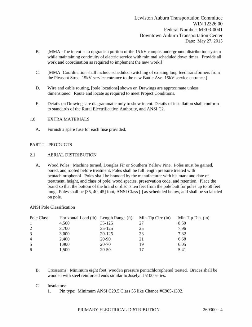
Lewiston Auburn Transportation CommitteeWIN 12326.00
Federal Number: ME03-0041Downtown Auburn Transportation Center
Date: May 27, 2015
PRIMARY ELECTRICAL DISTRIBUTION 260300 - 4
B. [MMA -The intent is to upgrade a portion of the 15 kV campus underground distribution system while maintaining continuity of electric service with minimal scheduled down times. Provide all work and coordination as required to implement the new work.]
C. [MMA -Coordination shall include scheduled switching of existing loop feed transformers from the Pleasant Street 15kV service entrance to the new Battle Ave. 15kV service entrance.]
D. Wire and cable routing, [pole locations] shown on Drawings are approximate unless dimensioned. Route and locate as required to meet Project Conditions.
E. Details on Drawings are diagrammatic only to show intent. Details of installation shall conform to standards of the Rural Electrification Authority, and ANSI C2.
1.8 EXTRA MATERIALS
A. Furnish a spare fuse for each fuse provided.
PART 2 - PRODUCTS
2.1 AERIAL DISTRIBUTION
A. Wood Poles: Machine turned, Douglas Fir or Southern Yellow Pine. Poles must be gained, bored, and roofed before treatment. Poles shall be full length pressure treated with pentachlorophenol. Poles shall be branded by the manufacturer with his mark and date of treatment, height, and class of pole, wood species, preservation code, and retention. Place the brand so that the bottom of the brand or disc is ten feet from the pole butt for poles up to 50 feet long. Poles shall be [35, 40, 45] foot, ANSI Class [ ] as scheduled below, and shall be so labeled on pole.
ANSI Pole Classification
Pole Class Horizontal Load (lb) Length Range (ft) Min Tip Circ (in) Min Tip Dia. (in)1 4,500 35-125 27 8.592 3,700 35-125 25 7.963 3,000 20-125 23 7.324 2,400 20-90 21 6.685 1,900 20-70 19 6.056 1,500 20-50 17 5.41
B. Crossarms: Minimum eight foot, wooden pressure pentachlorophenol treated. Braces shall be wooden with steel reinforced ends similar to Joselyn J5100 series.
C. Insulators:1. Pin type: Minimum ANSI C29.5 Class 55 like Chance #C905-1302.

Lewiston Auburn Transportation CommitteeWIN 12326.00
Federal Number: ME03-0041Downtown Auburn Transportation Center
Date: May 27, 2015
PRIMARY ELECTRICAL DISTRIBUTION 260300 - 5
2. Dead End Suspension Insulators: Minimum ANSI C29.2 Class 52. [NOTE TO DESIGNER: 5KV to 23KV]
D. Overhead Conductors: [Bare copper], [aluminum conductor, steel reinforced (ACSR)], or [AAAC], sized as indicated [or as required to support the intended loads]. [, minimum size #1/0 AWG] [ACSR construction: Bare aluminum alloy 1350-H19 wires, concentrically stranded about a Class A galvanized coated steel core wire, rated 240 Amperes.]
E. Guy Anchors: Power installed, minimum 12 inches or double 10 inch diameter helix with minimum [3/4][1] inch diameter rod.
F. Surge Arresters: Valve type conforming to NEMA LA1 arranged for crossarm mounting rated for [3KV, 6KV, or 9 KV] max.
G. Fused Cutouts: ANSI C37.42; Drop-out type fused cutouts rated [100] [200] [___] amperes at [14.4] [___] kV ungrounded.
H. Fuses: Type [T] [K], rated [as indicated] [as required] [ amperes.]
I. Provide other hardware and equipment as required and indicated for a complete installation. Acceptable manufacturers for pole line equipment are A.B. Chance, Joselyn, Westinghouse, G.E., G&W, S&C, and McGraw-Edison.
2.2 THREE-PHASE PAD-MOUNTED TRANSFORMERS, DEAD-FRONT
A. Acceptable Manufacturers:1. Cooper Power Systems (RTE) or equal.2. General Electric.3. Square D.4. ITE-Siemens.
B. ANSI C57.12.28 with separate Medium and low-voltage compartments, primary switching and fuses, [secondary circuit breaker[s],] and accessories. Tamper resistant welded weatherproof enclosure with interlocking doors and penta-head bolt/padlock handle assembly on low voltage door. Provide bolted access handhole at transformer top.
C. Compartments: Divided Medium and low-voltage compartments in sections with steel isolating barriers extending the full height and depth of the compartment.
D. Compartment Doors: hinged lift-off type with stop in open position and three-point latching.
E. Medium-Voltage Compartment: Contain the incoming line, insulated Medium-voltage load-break connectors, inserts, transformer Medium-voltage bushing wells, connector parking stands, [dead-front surge arresters,] [load-break switch handle], [access to Dry-well fuses][access to oil-immersed fuses], externally-operated padlockable no load tap changer, drain valve and sampler, and ground pad.1. Insulated Medium-voltage load-break connectors IEEE 386.

Lewiston Auburn Transportation CommitteeWIN 12326.00
Federal Number: ME03-0041Downtown Auburn Transportation Center
Date: May 27, 2015
PRIMARY ELECTRICAL DISTRIBUTION 260300 - 6
2. Bushing well and insert ratings:a. 95 kV BIL, rated voltage 8.3 kV for operation on a 4.16 kV system.b. Current rating: 200 amperes rms continuous.c. Fault Close-in: 10,000 A.d. Corona Extinction: 11 kV.
{OR}e. 125 kV BIL, rated voltage 8.3 kV for operation on a 12.47 kV system.f. Current rating: 200 amperes rms continuous.g. Fault Close-in: 10,000 A.h. Corona Extinction: 19 kV.
F. Load Break Inserts and Bushings Plus Load Break Elbows: The product of a single manufacturer and provide with the transformer to insure compatibility.
G. Load-break Elbow Connectors: Complete with steel reinforced hook-stick eye, grounding eye, and arc-quenching contact material all sized for the Medium voltage cable specified and provided with transformer to insure compatibility.
H. Load-break Oil Rotary Switch (LBOR): Four Position Sectionalizing Loop-feed oil-immersed type, gang-operated, spring loaded quick-make quick-break. Positions: 1. A-B-Coil (feed-thru), 2. B-Coil, 3. A-coil, 4. Open.1. Locate the switch handle in the Medium-voltage compartment.2. LBOR ratings:
a. 95 kV BIL, rated voltage 15.5 kV L-L, 8.3 kV L-G.b. Current rating: 200 amperes rms continuous.c. Making current: 12 kA RMS Sym/19.2 kA Assym.
{OR}d. 125 kV BIL, rated voltage 27 kV L-L, 15.5 kV L-G.e. Current rating: 200 amperes rms continuous.f. Making current: 12 kA RMS Sym/19.2 kA Assym.
I. Current Limiting Fuses Dry-well Mount: Fuses in air-insulated, oil-sealed, dead-front, load break or non-load-break dry-well fuse canisters and on the load side of the load-break switch. Interlock non-load-break type fuse canisters with the load-break switch so that the fuses may be removed only when the switch is in the "Off" position. The fuses shall remove the transformer from service in case of an internal fault. Size fuses to approximately 150 percent of the transformer rating, but in no case larger than the manufacturer's recommended size. The fuses shall have a peak let-through rating less than the switch rating. Furnish a spare fuse for each fuse provided.1. [In lieu of dry-well fuses, current limiting “Bay-O-Net” type load break fuses, Oil-
immersed but externally replaceable, with in series non accessible in oil fault fuses will be considered for approval.]
J. Parking stands: Provide a parking stand near each bushing well.

Lewiston Auburn Transportation CommitteeWIN 12326.00
Federal Number: ME03-0041Downtown Auburn Transportation Center
Date: May 27, 2015
PRIMARY ELECTRICAL DISTRIBUTION 260300 - 7
K. Low-voltage Compartment: Containing liquid temperature and level gages, cable lugs, low-voltage bushings, pressure relief valve, filling provisions, stainless steel transformer nameplate, and ground pad.
L. Transformer: Oil insulated, two winding, 60 hertz, 65 degree C rise above a 30 degree C average ambient, self-cooled type.1. Rated [75][112.5] [150][225][300][500][750][1000] kVA [as indicated on the Drawings].2. [[60 kV BIL, Medium voltage of 4.16] [95 kV BIL, Medium voltage of [12.47] [13.2]
[13.8]] kV [delta] [wye] primary, with four 2-1/2 percent full capacity taps two above and two below rated primary voltage.
3. Secondary voltage: [208Y/120] [480Y/277].4. Minimum tested impedance: Not less than [_**_] percent. ** [NOTE TO DESIGNER:
2.6% for 75kVA, 5.4% for 500kVA, 5.75% =>750kVA]5. Tap changer: Externally operated, manual type for changing tap setting when the
transformer is de-energized.6. Transformer kVA and voltage ratings: Conspicuously displayed on the exterior of its
enclosure.7. The transformer shall have an insulated low-voltage neutral bushing with removable
ground strap with lugs for ground cable.
M. [Insulating Liquid: Less flammable, edible-seed-oil based, and UL listed as complying with NFPA 70 requirements for fire point of not less than 300 deg C when tested according to ASTM D 92. Liquid shall be in conformance with FM Approval Standard 6933. Liquid shall be readily biodegradable and nontoxic. Listed less-flammable fluid meeting the requirements of National Electrical Code® Section 450-23 and the requirements of the National Electrical Safety Code (IEEE C2-1997), Section 15. The dielectric coolant shall be readily and completely biodegradable per EPA OPPTS 835.3100. The base fluid shall be 100% derived from edible seed oils with performance enhancing additives. The fluid shall be published under US EPA Environmental Technology Verification (ETV) requirements, and tested for compatibility with transformer components. The fluid shall be Factory Mutual Approved, UL® Classified Dielectric Medium (UL-EOUV) and UL Classified Transformer Fluid (UL-EOVK), Envirotemp® FR3® fluid.]
N. Corrosion Protection Using ALL Processes in Order Listed:1. Phosphate coating on pretreated, clean bare metal.2. Epoxy primer using a cationic electrodeposition dip process. Minimum 0.0005" thick.3. Baked-on Electrostatic thermosetting polyester powder spray. Minimum 0.0015" thick.4. Coating of urethane spray paint for final color. Minimum 0.0010" thick.5. Final color: [ASA 70 light gray][Green].
O. Warning Signs: Provide on door: "DANGER HIGH VOLTAGE KEEP OUT".
2.3 THREE-PHASE PAD-MOUNTED PRIMARY METERING STATION,[from USPS Hampden]
A. Manufacturer: Elliot Industries Cat# EPM-PMS-15-311P-E2.

Lewiston Auburn Transportation CommitteeWIN 12326.00
Federal Number: ME03-0041Downtown Auburn Transportation Center
Date: May 27, 2015
PRIMARY ELECTRICAL DISTRIBUTION 260300 - 8
B. Three phase, two poles per phase 200 amp air terminated bushing wells, NEMA standard outdoor enclosure.
C. Heavy duty 11 gauge welded steel construction outdoor enclosure with front and rear doors.
D. Dimensions: 72" wide x 48" deep x 48" high.
E. Front Access: Dead front construction with parking stands, two 200 amp air terminated bushing wells per phase.
F. Rear Access: Live front construction with 3/16" GPO 3 barriers between phases. Include all hardware as required to allow Power Co. to install instrument transformers. Coordinate details with Power Co.
G. Warning Signs: Provide on door: "DANGER HIGH VOLTAGE KEEP OUT".
2.4 UNDERGROUND DISTRIBUTION
A. Conduits for underground installation is specified under Section 260111 - Conduit.
B. [OR]Conduits And Duct Banks1. Conduits Specified Under Division 26 Section 260111 “Conduit.”2. Duct Banks: Minimum concrete cover all sides as indicated on drawings. Form sides for
smooth finish to minimize frost action.3. Concrete for Duct Banks: Specified under Division 03 Section 033000 “Cast-In-Place
Concrete”: Minimum 3000 psi concrete with one-inch maximum aggregate.4. Trenching, Backfill, Earthwork: Specified under Division 31 and 32.5. Separators: High impact polystyrene, spacing as indicated. Stagger the joints of the
conduits by rows and layers.6. See Drawings for details.
C. Medium Voltage Wires and Cables: Shielded cable, copper conductors.1. Rated: 15kV, 133 percent insulation level.2. Conductor: Annealed uncoated copper, compact stranded per ASTM B-496.3. Conductor Screen: Extruded semiconducting EPR conforming to ICEA S-94-649 and
AEIC CS8.4. Insulation: Ethylene-propylene based (EPR) conforming to ICEA S-94-649 AEIC CS8.5. Insulation Screen: Extruded semiconducting EPR conforming to ICEA S-93-639/NEMA
WC74, S-97-682, AEIC CS8 and UL1072.6. [Concentric conductor: Bare copper wires, 1/3 neutral capacity.]7. [OR Shield: 5mil Bare copper tape helically applied with 25% overlap.]8. Jacket: Polyvinyl chloride (PVC), oil, acid, chemical and sunlight resistant.9. Designed for both wet and dry locations.10. [Equal to Okonite type URO-J, sized as indicated.]11. [OR Equal to Okonite type MV-105, sized as indicated.]12. Shall meet the following manufacturers’ published data:

Lewiston Auburn Transportation CommitteeWIN 12326.00
Federal Number: ME03-0041Downtown Auburn Transportation Center
Date: May 27, 2015
PRIMARY ELECTRICAL DISTRIBUTION 260300 - 9
Conductor Size AMPS Direct Burial AMPS Underground Duct
2 AWG 225 165
1 AWG 260 185
1/0 AWG 295 2152/0 AWG 335 245
3/0 AWG 380 275
4/0 AWG 435 315
250 kcmil 475 345
350 kcmil 575 415
500 kcmil 700 500
Three Conductor 105 deg C, 100% load, Earth Temp 20 deg C, RHO=90
D. Lightning Arresters: M.O.V.E. deadfront Arrester designed to plug in same as a loadbreak elbow. Ratings selected by manufacturer of the pad transformer for the voltage indicated. Provide one per phase on source side at pad using load break feed thru inserts. Provide proper grounding.
E. [OR] Lightning Arresters: M.O.V.E. deadfront Arrester designed to plug in same as a load break elbow. Provide one per phase [on source side] at each loop feed pad mounted transformer [locations where shown on 15kV One-Line,] using load break feed thru inserts. Provide proper grounding. Rated min 7.65 kV, max 9kv. Provide proper grounding.
F. [Fault Circuit Indicators (FCI): Provide one per phase on opposite side of Arrester at each loop feed pad mounted transformer. FCI shall be equal to Cooper Power Systems S.T.A.R. 15 kV Test Point Reset style with the following features:1. High/Low Trip Rating.2. Inrush Restraint.3. Temperature Compensation.4. Low Pass Filter5. Single Hot-Stick Installation.6. Automatic Reset.7. Open-Core CT Design.8. Flag Display.9. Test Point Adapter Kit.10. Line/Self Powered.]
G. Medium Voltage Load Break Dead Front Termination: 1. Loadbreak Feedthru Inserts: Conforming to ANSI/IEEE Standard 386 for 200A, 15kV
Class. Compatible with bushing wells/inserts of associated equipment. Use on Source side to allow installation of the M.O.V.E. deadfront Arrester.
2. Load Break Elbows: Conforming to ANSI/IEEE Standard 386 for 200A, 15kV Class. Compatible with bushing wells/inserts of associated equipment. Elbows shall have an optional capacitive test point, made of corrosion resistant plastic, for use with fault indicators. Provide insulated cap for elbows that do not require FCI. Loadbreak Elbow Connectors shall be fully-shielded and insulated plug-in termination for connecting
Lewiston Auburn Transportation CommitteeWIN 12326.00
Federal Number: ME03-0041Downtown Auburn Transportation Center
Date: May 27, 2015
PRIMARY ELECTRICAL DISTRIBUTION 260300 - 10
underground cables to transformers, switching cabinets and junctions equipped with loadbreak bushings.
3. Load break Multiple Point Junctions: Fully shielded, submersible, separable connection for load break operation. 200A, 15kV Class, separable insulated connector systems with four 8.3/14/4 kV load break interfaces, internally bussed together meeting requirements of ANSI/IEEE Standard 386. Adjustable hot-dipped galvanized support bracket with 90 degree tilt in 10 degree increments, designed for direct mounting to wall. Load break interfaces designed to receive load break elbows herein specified.
4. Load Break Dead Front Terminations shall be as manufactured by Cooper Power Systems or equal.
H. [Medium Voltage Termination:1. Medium Voltage Cable Terminations: IEEE 48 Class 1 (exterior wet locations). Include
all components, and materials which shall include stress relief cones/ devices, plus complete manufacturer's instructions for installation.
2. Cast Epoxy Resin Type Termination: IEEE 48, Class 1, terminating single conductor, solid insulated, nonmetallic jacketed type cables for service voltage up to 15 kV outdoors. Terminations for shielded conductors shall include stress control, with a shield ground
connection brought out through the insulation and covering, and grounded at installation. Terminations exposed to the weather shall include porcelain insulator and weather shield.]
I. Medium Voltage Permanent Splices:1. Medium Voltage Cable Splices: IEEE 48 Class 1 (exterior wet locations). 15kV, 200A,
permanent, fully-shielded, fully submersible cable joint, EPDM rubber, designed specifically for the medium voltage cables being spliced. Manufactured in full compliance with all applicable IEEE standards, 404 and 592. Include all components, and materials which shall include stress relief cones/ devices, plus complete manufacturer's instructions for installation.
2. As manufactured by Cooper Power Systems, One-Piece EZ II Splice or equal.
PART 3 - EXECUTION
3.1 GROUNDING ELECTRODES
A. Provide driven ground rods as specified in [Division 26 Section 260170 “Grounding and Bonding”].
{OR}
B. Rod Electrodes: ITT Blackburn, Copper-clad carbon steel, 3/4" Diameter, minimum length: Sectional 10 feet.
C. Use only "Acorn" style ground clamps for connections to rods.{OR}
D. Connect ground conductors to the upper end of the ground rods by exothermic weld.

Lewiston Auburn Transportation CommitteeWIN 12326.00
Federal Number: ME03-0041Downtown Auburn Transportation Center
Date: May 27, 2015
PRIMARY ELECTRICAL DISTRIBUTION 260300 - 11
E. Provide compression connectors at equipment end of ground conductors.
3.2 GROUNDING
A. Grounding: NFPA 70 and ANSI C2, and Power Company requirements, except that grounds and grounding systems shall have a resistance to solid earth ground not exceeding 5 ohms. Provide multiple ground rods as required.
B. Make joints in grounding conductors and taps to ground ring by exothermic weld, Cadweld or equal.
3.3 PAD-MOUNTED TRANSFORMER GROUNDING
A. Grounding: NFPA 70 and ANSI C2, and Power Company requirements, except that grounds and grounding systems shall have a resistance to solid earth ground not exceeding [5] ohms. Provide multiple ground rods as required.
B. Connect copper grounding conductors to the ground loop as specified. In addition to the bonding strap provided by the manufacturer, provide a ground conductor from the transformer secondary neutral to the ground loop.
C. Make joints in grounding conductors and taps to ground ring by exothermic weld, Cadweld or equal.
3.4 INSTALLATION OVERHEAD WORK
A. Set poles in alignment and plumb except, at points of strain. Rake poles against the strain 2"-4" per ten feet of pole height or as required so that poles are vertical after line installation. Pole holes shall be at least eight inches larger in diameter than the pole butt and be at least as large at the top as at the bottom. Thoroughly tamp pole backfill for the full depth of the hole and mound excess fill around the pole. Setting depths shall be [minimum 7'-0", except as indicated] [as scheduled below].
B. Place anchors in line with the strain and a distance from the pole equal to the vertical distance from the pole ground line to the point of guy attachment on the pole. Anchors and guys shall be capable of holding the planned loads to which they are applied.
C. All overhead line work shall be performed by personnel well experienced in this type of work and all work shall be done in accordance with recognized safety standards including those of OSHA and other regulatory agencies.
D. Install conductors to ANSI/IEEE C2 and tension to proper sag values. All splices shall exceed the ultimate strength of the conductor and be of the type recommended by the conductor manufacturer.

Lewiston Auburn Transportation CommitteeWIN 12326.00
Federal Number: ME03-0041Downtown Auburn Transportation Center
Date: May 27, 2015
PRIMARY ELECTRICAL DISTRIBUTION 260300 - 12
E. Identify each pole using aluminum marker stamped with characters 2-1/2 inches (60 mm) high minimum. Locate to provide maximum visibility [from roadway] and fasten with aluminum nails. Obtain identifying numbers from [____________________.]
F. Set crossarms at right angles to line for straight runs; and to bisect the angle of turns in line direction.
G. Provide two braces for each crossarm.
3.5 INSTALLATION UNDERGROUND WORK
A. Earthwork: Excavation, backfilling, and pavement repairs for electrical requirements are specified under Divisions 31, 32, 33.
B. Install and make all final connections to pad-mounted transformers furnished under this section as indicated on project drawings, the approved shop drawings, and as specified herein. Mount transformers on concrete slab and secure with at least four anchor bolts.
C. [Disconnect, remove and re-install pad mounted transformers for _________ as indicated.]
D. Precast Manholes [Handholes]: Provide and installed under Division 03 Section “Precast Concrete”, complete with [sumps,] drain facilities, ladder, and all accessories, as detailed on Drawing [E-4].
[OR]
E. Precast Manholes / Handholes: Provide and installed under Div 31, 32, 33. 1. Under Division 26 Section 260300, provide ladder, grounding and all accessories
necessary to allow for the Div 26 work.
F. Grounding:1. Ground Rods: Install in each [existing and new] electric manhole and handhole, at a
convenient point close to the wall, a 3/4-inch by 10-foot copper-clad steel ground rod. Approximately 4 inches of the ground rod shall extend above the floor. Properly connected to the cable shielding, metallic sheath, and armor at each cable joint or splice by means of No.4 AWG or equivalent braided tinned copper wire. Ground wires shall be neatly and firmly attached to manhole and handhole walls and shall be connected to all metallic surfaces.
2. Counterpoise / Fault current grounding: In all conduit paths containing Medium voltage cables, include a 4/0 bare copper grounding conductor. Cadweld to manhole, handhole, and tranformer pad ground rods and all metal associated metallic surfaces.
G. Cable Pulling: Test duct lines with a mandrel and thoroughly swab out to remove foreign material before the pulling of cables. Pull cables down grade with the feed-in point at the manhole or buildings of the highest elevation. Accumulate cable slack at each manhole or junction box and train the cable around the interior to form one complete loop. Minimum allowable bending radii shall be maintained in forming such loops.

Lewiston Auburn Transportation CommitteeWIN 12326.00
Federal Number: ME03-0041Downtown Auburn Transportation Center
Date: May 27, 2015
PRIMARY ELECTRICAL DISTRIBUTION 260300 - 13
1. Lubricants for assisting in the pulling of jacketed cables shall be those specifically recommended by the cable manufacturer.
2. Cable pulling tensions shall not exceed the maximum pulling tension recommended by the cable manufacturer.
H. Installation of Cables in Manholes, Handholes [and Vaults]:1. Do not install cables utilizing the shortest route, but route along those walls providing the
longest route and the maximum spare cable lengths.2. Form all cables to closely parallel walls, not to interfere with duct entrances, and support
on brackets and cable insulators at a maximum of 18 inches.3. Support cable splices in underground structures by racks on each side of the splice.
Locate splices to prevent cyclic bending in the spliced sheath.4. [In existing manholes; handholes and vaults where new ducts are to be terminated or
where new cables are to be installed, coordinate with the existing installation of cables, cable supports and grounding as required for a neat and workmanlike installation with all cables properly arranged and supported.]
I. Cable Terminating: Install all terminations in accordance with the manufacturer's requirements. Make terminations using materials and methods designated by the written instructions of the cable manufacturer and termination kit manufacturer.
J. Splices for 600 Volt Class Cables: Locate splices in underground systems only in accessible locations such as manholes and handholes. Use compression connector on the conductor and insulate and waterproof by one of the following methods suitable for continuous submersion in water.1. Cast-type splice insulation by means of molded casting process employing a thermosetting
epoxy resin insulating material and apply by a gravity poured method or by a pressure injected method. The component materials of the resin insulation shall be in a packaged form ready for mixing without removing from the package.
2. Gravity poured method: Employ materials and equipment contained in an approved commercial splicing kit which includes a mold suitable for the cables to be spliced.
K. Splices in Medium Voltage Cables: Intent is to not allow splicing. Splicing may be allowed do to existing condition and only after specific written approval from the engineer. Were allowed, splices shall be suitable for continuous immersion in water and shall be made only in accessible locations in manholes or handholes.1. Cast-Type Splice Methods: Cast-type splice insulation shall be provided by means of a
molded casting process employing a thermosetting epoxy resin insulating material which shall be applied by a gravity poured method or by a pressure injected method. The component materials of the resin insulation shall be in a packaged form ready for mixing without removing from the package.
2. Kit Methods: Medium voltage splices made using a "kit" shall be the product of one manufacturer and shall have the approval in writing of the manufacturer of the cable which is to be spliced.
3. Splices in Shielded Cables: Splices in shielded cables shall include covering the spliced area with metallic tape, or like material, to the original cable shield and by connecting it to the cable shield on each side of the splice. Provide a No. 6 AWG bare copper ground
Lewiston Auburn Transportation CommitteeWIN 12326.00
Federal Number: ME03-0041Downtown Auburn Transportation Center
Date: May 27, 2015
PRIMARY ELECTRICAL DISTRIBUTION 260300 - 14
connection brought out in a watertight manner and grounded to a 3/4 inch by 10 foot ground rod as part of the splice installation.
L. Fireproofing Tape for Medium Voltage Cable: Strips of fireproofing tape approximately 1/16-inch thick by 3 inches wide shall be wrapped tightly around each cable spirally in half-lapped wrapping, or in two butt-joined wrappings with the second wrapping covering the joints in the first. The tape shall be applied with the coated side toward the cable and shall extend one inch into the ducts. To prevent unraveling, the fireproofing tape shall be random wrapped the entire length of the fireproofing with pressure sensitive glass cloth tape. The fireproofing tape shall consist of a flexible, conformable fabric having one side coated with flame retardant, flexible, polymeric coating and/or a chlorinated elastomer not less than 0.050 inch thick and shall weight not less than 2.5 pounds per square yard. The tape shall be non-corrosive to cable sheath, shall be self-extinguishing, and shall not support combustion. The tape shall not deteriorate when subjected to oil, water, gases, salt water, sewage and fungus.
3.6 TESTING
A. Provide earth ground testing at each existing transformer, manhole and vault. 1. Resistance of the grounding electrode system shall be measured using an earth ground
testers that can perform earth ground loop resistances using only clamps (Stakeless testing). This method shall not require the use of earth ground stakes or the disconnection of ground rods. Tester shall automatically determine the ground loop resistance at the grounding connection. Clamp-0n earth ground resistance tester jaws shall clamp completely around the conductor to be tested.
2. If ground resistance is over 5 ohms, then install a second ground rod.
B. Medium Voltage Cables: After installation, and before placing in service, perform a D.C. High Potential Test on all cables rated above 600 volts. All precautions and limits as specified in the applicable standards shall be adhered to. Current sensing circuits in test equipment shall measure only the leakage current associated with the cable under test, and shall not include internal leakage current of the test equipment. Test procedures shall be as follows and the results for each cable test shall be recorded.1. Record temperature and relative humidity. Do not perform tests unless weather is clear
and relative humidity is low.2. Each conductor shall be individually tested with all other conductors grounded. All
shields shall be grounded.3. Terminations shall be properly corona suppressed by guard ring, field reduction sphere, or
other suitable methods.4. Perform megger and continuity test prior to high-pot.5. A D.C. high potential shall be applied in at least five equal increments until maximum
test voltage is reached. The D.C. leakage current shall be recorded at each step after a constant stabilization time consistent with system charging current decay. 100% voltage shall be reached in a maximum of 60 seconds.
6. A graphic plot shall be made of leakage current (X axis) versus voltage (Y axis) at each increment.
7. The test conductor shall be raised to a maximum test voltage and held for a total of 15 minutes. Readings of leakage current (Y axis) versus time (X axis) shall be recorded and

Lewiston Auburn Transportation CommitteeWIN 12326.00
Federal Number: ME03-0041Downtown Auburn Transportation Center
Date: May 27, 2015
PRIMARY ELECTRICAL DISTRIBUTION 260300 - 15
plotted. Take values at 15 seconds, 30 seconds, 60 seconds, then one minute interval till end of test.
8. The conductor test potential shall be reduced to zero and grounds applied for at least ten minutes to discharge the cable.
9. The maximum D.C. test voltage shall be as recommended by the cable manufacturer and by IPCEA for "Voltage Tests After Installation".
10. When new cables are spliced into existing cables, the high potential test shall be performed on the new cable prior to splicing. After test results are approved for new cable and splice is made, an insulation resistance test and continuity test shall be performed on the length of cable including the splice; the existing cable shall be tested to the nearest disconnection point. Written results shall be submitted for approval.
[OR if used cable or no $$ for HiPot]
C. Typical medium voltage cable D.C. High Potential testing is not required on this project.
D. Perform Insulation-Resistance Test on each field-installed conductor with respect to ground and adjacent conductors. 1. Applied potential shall be 1,000 volts dc for 600 volt rated cable and 5,000 volts dc for
medium voltage cables. 2. Take readings after 1 minute and until the reading is constant for 15 seconds. 3. Minimum insulation-resistance values shall not be less than 100 Megohms. If lower
readings are measured, contact the cable manufacturer for trouble shooting and for authorization to energize.
END OF SECTION 260300

Lewiston Auburn Transportation CommitteeWIN 12326.00
Federal Number: ME03-0041Downtown Auburn Transportation Center
Date: May 27, 2015
PRIMARY ELECTRICAL DISTRIBUTION 260300 - 16
This Page Left Intentionally Blank

Lewiston Auburn Transportation CommitteeWIN 12326.00
Federal Number: ME03-0041Downtown Auburn Transportation Center
Date: May 27, 2015
SERVICE ENTRANCE 260420 - 1
SPECIAL PROVISIONSECTION 260420
SERVICE ENTRANCE
PART 1 - GENERAL
1.1 WORK INCLUDES
A. Arrangement with Power Company for permanent electric service.
B. Arrange with Power Company to provide for metering.
C. Primary cables, aerial and underground lines, poles, switching, fuse protection and pad mounted transformers.
1.2 RELATED SECTIONS
A. Division 26 Section 260010 “Basic Electrical Requirements.”
B. Division 26 Section 260111 “Conduit.”
C. Division 26 Section 260123 “Wire and Cable.”
D. Division 26 Section 260130 “Boxes.”
E. Division 26 Section 260170 “Grounding and Bonding.”
1.3 SYSTEM DESCRIPTION
A. System Voltage: 120/208 volts, three phase, four wire, 60 Hertz.
1.4 REFERENCES
A. NEMA Standards.
B. NFPA 70 (N.E.C.) latest edition.
C. U.L. Standards.
D. ANSI Standards.
1.5 REGULATORY REQUIREMENTS
A. Conform to requirements of ANSI/NFPA 70. (N.E.C.).

Lewiston Auburn Transportation CommitteeWIN 12326.00
Federal Number: ME03-0041Downtown Auburn Transportation Center
Date: May 27, 2015
SERVICE ENTRANCE 260420 - 2
B. Furnish products listed and classified by Underwriters Laboratories, Inc. (U.L.) as suitable for purpose specified and shown.
C. Power Company: Central Maine Power Co. - Contact: Dan Begin
D. Install in accordance with Power Company's rules and regulations.
1.6 SUBMITTALS
A. Submit Shop Drawings, Owner's Manuals, and Operating Instructions in accordance with Division 01 Section “Submittal Procedures”.
B. Include modular metering equipment
PART 2 - PRODUCTS
2.1 METERING EQUIPMENT
A. Self contained 200 Amp 3 phase 4 wire. Size and details as approved by the Power Company.
B. Meter Socket: As listed and approved by the Power Company.
2.2 SECONDARY CONDUCTORS
A. Specified Under Division 26 Section 260123 “Wire and Cable.”
2.3 CONDUITS
A. Specified Under Division 26 Section 260111 “Conduit.”
PART 3 - EXECUTION
3.1 INSTALLATION
A. Make arrangements with Power Company to obtain permanent electric service to the Project.
B. Overhead: Install service rack and weatherhead at height as required by Power Company. Power Company will connect service drop to service entrance conductors.
C. Underground: Install service entrance conduits [in concrete envelope] from [property line] [Power Company's manhole] [Power Company's terminal pole] [Power Company's pad-mountedtransformer] to building service entrance equipment.
[AND/OR]

Lewiston Auburn Transportation CommitteeWIN 12326.00
Federal Number: ME03-0041Downtown Auburn Transportation Center
Date: May 27, 2015
SERVICE ENTRANCE 260420 - 3
D. Underground Secondary: Install service entrance conduits in concrete envelope from Power Company's pad-mounted transformer to building service entrance equipment.
[AND/OR]
E. Underground Primary: Install service entrance conduits in concrete envelope where located within the State of Maine right of way, [where crossing paved ways or as specifically detailed] from Power Company's Riser pole to Power Company's pad-mounted transformer.
F. Concrete Pad for Transformer: Coordinate specific details and location with Power Company and obtain approvals prior to installation of pad.
3.2 PAD-MOUNTED TRANSFORMER GROUNDING
A. Grounding: NFPA 70 and ANSI C2, and Power Company requirements, except that grounds and grounding systems shall have a resistance to solid earth ground not exceeding 10 ohms. Provide multiple ground rods as required.
3.3 INSTALLATION UNDERGROUND WORK
A. Earthwork: Excavation, backfilling, and pavement repairs for electrical requirements are specified under Divisions 31, 32, 33.
END OF SECTION 260420

Lewiston Auburn Transportation CommitteeWIN 12326.00
Federal Number: ME03-0041Downtown Auburn Transportation Center
Date: May 27, 2015
SERVICE ENTRANCE 260420 - 4
This Page Left Intentionally Blank
Lewiston Auburn Transportation CommitteeWIN 12326.00
Federal Number: ME03-0041Downtown Auburn Transportation Center
Date: May 27, 2015
DISCONNECT SWITCHES 260440 - 1
SECTION 260440DISCONNECT SWITCHES
PART 1 - GENERAL
1.1 WORK INCLUDES
A. Disconnect Switches.
B. Fuses.
C. Enclosures.
1.2 RELATED SECTIONS
A. Division 26 Section 260010 “Basic Electrical Requirements.”
B. Division 26 Section 260170 “Grounding and Bonding.”
C. Division 26 Section 260180 “Equipment Wiring.”
D. Division 26 Section 260195 “Electrical Identification.”
E. Division 26 Section 260470 “Panelboards.”
1.3 REFERENCES
A. NEMA Standards.
B. NFPA 70 (N.E.C.) Latest Edition.
C. U.L. Standards.
D. ANSI Standards.
1.4 PERFORMANCE REQUIREMENTS
A. Conform to requirements of ANSI/NFPA 70. (N.E.C.)
B. Furnish products listed and classified by Underwriters' Laboratories, Inc. (U.L.) as suitable for purpose specified and shown.
C. Size per N.E.C. and Equipment Manufacturers' Recommendations.
1.5 SUBMITTALS
A. Submit Shop Drawings, Owner's Manuals, and Operating Instructions in accordance with Division 01 Section “Submittal Procedures.”

Lewiston Auburn Transportation CommitteeWIN 12326.00
Federal Number: ME03-0041Downtown Auburn Transportation Center
Date: May 27, 2015
DISCONNECT SWITCHES 260440 - 2
B. Include outline drawings with dimensions, and equipment ratings for voltage, capacity, horsepower, and short circuit.
1.6 SPARE PARTS
A. Fuses: Furnish to Owner three (3) spare fuses for each circuit and each device requiring fuses. Maximum of six (6) spare fuses of each type and rating installed.
B. Fuse Cabinet: Provided under Division 26 Section 260470 - Panelboards.
C. Fuse Pullers: Furnish one fuse puller to Owner.
PART 2 - PRODUCTS
2.1 DISCONNECT SWITCHES
A. Acceptable Manufacturers:1. Cutler Hammer.2. I-T-E Siemens.3. General Electric.4. Square D.
B. Fusible Switch Assemblies: Heavy-duty, quick-make, quick-break, load interrupter enclosed knife switch with externally operable handle interlocked to prevent opening front cover with switch in ON position. Handle lockable in OFF position. Fuse Clips: Designed to accommodate Class R fuses.
C. Nonfusible Switch Assemblies: Heavy-duty, quick-make, quick-break, load interrupter enclosed knife switch with externally operable handle interlocked to prevent opening front cover with switch in ON position. Handle lockable in OFF position.
D. Rated: Horsepower rated, 250-volt as required by the particular circuit with ampere rating and number of poles as indicated, or as required by the specific equipment.
E. Enclosures: NEMA KS 1; Type 1 for interior dry locations, Type 3R raintight for exterior locations. Type 4 gasketed for wash down areas in kitchens.
2.2 FUSES
A. Acceptable Manufacturers:1. Bussman.2. Gould Shawmut.3. Littelfuse.
B. Fuses 600 Amperes and Less: Dual element time delay current limiting Class RK5 (Dual Element Time Delay); 250 volt.
C. Interrupting Rating: 200,000 RMS amperes.
Lewiston Auburn Transportation CommitteeWIN 12326.00
Federal Number: ME03-0041Downtown Auburn Transportation Center
Date: May 27, 2015
DISCONNECT SWITCHES 260440 - 3
2.3 FUSE CABINET:
A. Fuse Cabinet: Sized to contain all spare fuses required plus 25% room for future use. Provide with engraved nameplate.
PART 3 - EXECUTION
3.1 INSTALLATION
A. See Section Division 26 260180 “Equipment Wiring.”
B. Install fuses in fusible disconnect switches.
C. Mount fuse cabinet in main electrical room.
END OF SECTION 260440

Lewiston Auburn Transportation CommitteeWIN 12326.00
Federal Number: ME03-0041Downtown Auburn Transportation Center
Date: May 27, 2015
DISCONNECT SWITCHES 260440 - 4
This Page Left Intentionally Blank

Lewiston Auburn Transportation CommitteeWIN 12326.00
Federal Number: ME03-0041Downtown Auburn Transportation Center
Date: May 27, 2015
PANELBOARDS 260470 - 1
SPECIAL PROVISIONSECTION 260470
PANELBOARDS
PART 1 - GENERAL
1.1 SECTION INCLUDES
A. Panelboards.
B. Individually mounted circuit breakers.
C. Metering
1.2 RELATED SECTIONS
A. Division 01 Section "Submittal Procedures."
B. Division 06 Section "Rough Carpentry."
C. Division 09 Section "Painting."
D. Division 26 Section 260010: Basic Electrical Requirements.
E. Division 26 Section 260170: Grounding and Bonding.
1.3 REFERENCES
A. NEMA Standards.
B. NFPA 70 N.E.C. Latest Edition.
C. U.L. Standards.
1.4 PERFORMANCE REQUIREMENTS
A. Conform to requirements of ANSI/NFPA 70 (N.E.C.).
B. Furnish products listed and classified by Underwriters Laboratories, Inc. (U.L.) as suitable for purpose specified and shown.
C. Size per Drawings.

Lewiston Auburn Transportation CommitteeWIN 12326.00
Federal Number: ME03-0041Downtown Auburn Transportation Center
Date: May 27, 2015
PANELBOARDS 260470 - 2
1.5 SUBMITTALS
A. Submit Shop Drawings, Owners' Manuals, and Operating Instructions in accordance with Division 01 Section "Submittal Procedures."
B. Include outline and support point dimensions, voltage, main bus ampacity, integrated short circuit ampere rating, circuit breaker arrangement, catalog, specification and sizes, panel dimensions, and gutter space.
1.6 SPARE PARTS
A. Keys: Furnish to Owner 1 key for each panel. All panels shall be keyed alike.
PART 2 - PRODUCTS
2.1 ACCEPTABLE MANUFACTURES - PANELBOARDS
A. General Electric.
B. Eaton.
C. Siemens.
D. Schneider Electric (Square D).
2.2 PANELBOARDS RATED 400AMPERE AND LESS
A. Circuit breaker type with mains and circuits as indicated on the Drawings and designed for one phase, three wire or three phase, four wire, solid neutral, 60 cycle service rated for 120/208 volt service as scheduled.
B. Enclosure: NEMA Type 1 except as noted. Code gauge galvanized steel boxes and enameled steel fronts sized for 6" minimum side, top and bottom gutters, or greater as required by NEC.
C. Flush or surface mounting as indicated by the panel schedule, concealed hinge and flush lock all keyed alike.
D. Bus: Copper ratings as scheduled on Drawings. Provide subfeed and feed-through lugs as required. Lugs designed for use for both copper and aluminum conductors. Subfeed shall signify that lugs are
tapped ahead of buses and feed-through shall signify that lugs are tapped on load side of the main and buses.
E. Neutral Bar: Copper, full size insulated from the cabinet and provided with lugs for each branch circuit space in the panel.
F. Bonding strap securely attached to the cabinet with lugs as required to receive the bonding conductors indicated and specified.

Lewiston Auburn Transportation CommitteeWIN 12326.00
Federal Number: ME03-0041Downtown Auburn Transportation Center
Date: May 27, 2015
PANELBOARDS 260470 - 3
G. Minimum Integrated Short Circuit Rating: 1. As indicated on drawings
H. Molded Case Circuit Breakers: Toggle type thermal-magnetic, quick-make, quick-break, with silver-plated contacts, bolt-in type, and with common trip for multiple circuits. Breakers shall have a nominal thickness of 1" per pole. Provide circuit breakers UL listed as Type SWD for switching lighting circuits. Provide UL Class A ground fault interrupter circuit breakers where indicated.
I. Bedroom Circuit Breakers: UL listed as Arc-Fault Circuit Interrupter.
2.3 INDIVIDUALLY MOUNTED CIRCUIT BREAKERS
A. Molded Case Circuit Breakers: As specified above for Panelboards.
B. Enclosure: NEMA Type 1 general purpose except as noted.
C. Flush or surface mounted as indicated.
PART 3 - EXECUTION
3.1 INSTALLATION
A. Install panelboards plumb and properly secured. Recessed panels shall be flush with wall finishes.
B. Height: Per N.E.C.
C. Provide filler plates for unused spaces in panelboards.
D. Provide typed directory completely filled-in indicating outlets, fixtures, devices, and locations served by the circuit. Revise directory to reflect circuiting changes required to balance phase loads.
E. Finish painting of flush panelboards and individually mounted breakers shall be as specified in Division 09 Section "Painting".
F. Properly support backboards, and panels. At non structural walls, provide separate support system for panelboards and equipment. Use UNISTRUT P5000 channels or equal. Length and spacing to form rigid separate wall. In other areas, coordinate with Division 06 Section "Rough Carpentry", to provide blocking as required.
3.2 FIELD QUALITY CONTROL
A. Measure steady state load currents at each panelboard feeder. Should the difference at any panelboard between phases exceed 20 percent, rearrange circuits in the panelboard to balance the phase loads within 20 percent. Take care to maintain proper phasing for multi-wire branch circuits.
Lewiston Auburn Transportation CommitteeWIN 12326.00
Federal Number: ME03-0041Downtown Auburn Transportation Center
Date: May 27, 2015
PANELBOARDS 260470 - 4
B. Visual and Mechanical Inspection: Inspect for physical damage, proper alignment, anchorage, and grounding. Check proper installation and tightness of connections for circuit breakers, fusible switches, and fuses.
3.3 PANELBOARD SCHEDULE
A. See Drawings.
END OF SECTION 260470

Lewiston Auburn Transportation CommitteeWIN 12326.00
Federal Number: ME03-0041Downtown Auburn Transportation Center
Date: May 27, 2015
LUMINAIRES 260510 - 1
SPECIAL PROVISIONSECTION 260510
LUMINAIRES
PART 1 - GENERAL
1.1 SECTION INCLUDES
A. Interior and exterior luminaires and accessories.
B. Exterior luminaires, and accessories.
C. Drivers
D. Dimming Drivers
E. Additional wiring methods for luminaires.
1.2 RELATED SECTIONS
A. Division 26 Section 260010: Basic Electrical Requirements.
B. Division 26 Section 260111: Conduit.
C. Division 26 Section 260123: Wire and Cable.
D. Division 26 Section 260130: Boxes.
E. Division 26 Section 260170: Grounding and Bonding.
1.3 REFERENCES
A. NEMA Standards.
B. NFPA 70 N.E.C. Latest Edition.
C. U.L. Standards.
D. ANSI/NFPA 101 - Life Safety Code.
1.4 PERFORMANCE REQUIREMENTS
A. Conform to requirements of ANSI/NFPA 70 (N.E.C.).
B. Furnish products listed and classified by Underwriters' Laboratories, Inc. (U.L.) as suitable for purpose specified and shown.

Lewiston Auburn Transportation CommitteeWIN 12326.00
Federal Number: ME03-0041Downtown Auburn Transportation Center
Date: May 27, 2015
LUMINAIRES 260510 - 2
C. Luminaire and pole sized for minimum 90 m.p.h. steady wind with 1.3 gust factor.
1.5 SUBMITTALS
A. Submit Shop Drawings, Owner's Manuals, and Operating Instructions in accordance with Division 01 Section “Submittal Procedures”.
B. Shop Drawings: Indicate dimensions and components for each luminaire that is not a standard product of the manufacturer.
C. Product Data: Provide dimensions, ratings, performance data and total input watts.
D. Product Data - Driver: Provide ratings and performance data.
E. Manufacturer's Instructions: Include instructions for storage, handling, protection, examination, preparation, and installation of product.
1.6 DELIVERY, STORAGE, AND HANDLING
A. Accept materials on site. Inspect for damage.
B. Protect from moisture, corrosion and entrance of debris by storing above grade. Provide appropriate covering.
1.7 SPARES
A. Provide two of each louver type.
B. Provide two of each plastic lens type.
C. Provide replacement driver for each driver type installed as follows: 1. 1% of total drivers per type installed.2. Minimum of 2 drivers for each type installed.
1.8 PROJECT CONDITIONS
A. Wiring to fixtures as shown on Drawings is diagrammatic only and is intended to show circuit and switching arrangements. Fixtures shall not be used as raceways except as specifically allowed by N.E.C. Art 410.
B. Where panel designation and circuit numbers are shown with no homerun symbol, wiring to same circuits may share same homerun to panel. See voltage drop and distance restrictions in Division 26 Section 260010.

Lewiston Auburn Transportation CommitteeWIN 12326.00
Federal Number: ME03-0041Downtown Auburn Transportation Center
Date: May 27, 2015
LUMINAIRES 260510 - 3
PART 2 - PRODUCTS
2.1 LUMINAIRES
A. Furnish products as specified in schedule on Drawings.
B. All fixtures shall be approved by Underwriters' Laboratories, Inc., and bear Underwriters' labels.
C. In addition to the manufacturers listed on the Drawings, fixtures with equivalent details and matching characteristics as provided by manufacturers listed below shall be considered for approval after review of Shop Drawings.
D. Manufacturers:HaloColumbiaExcelineCooper DaybriteDelta
ExcelineHolophaneHubbleICE (ICON)KeeneBenjamin
Insight LightingKeystoneKIMLightolierLitecontrolLithonia
MoldcastPeerlessQLSpauldingSPIWinona
E. Driver: Provide driver suitable for configuration specified.
F. Lamps: All lamps shall be furnished and installed in each fixture.
G. LED Dimming Driver:1. Equal to Advance Xitanium (0-10V).2. Fully electronic designed to operate properly on the LED sources indicated. Coordinate with
LED manufacturer for compatibility.3. Drivers shall have a Class A sound rating.4. Dimming shall be controlled by a Class 1 or Class 2 low-voltage 0-10V circuit.5. Driver shall operate LEDs at a frequency of 60 Hz.6. Drivers shall operate from 50/60 Hz input source of 120V or 277V with sustained variations
of +/- 10% (voltage and frequency) with no damage to the drive..7. Driver shall have a Power Factor greater than 90% and the input current shall have Total
Harmonic Distortion (THD) of less than 20%.8. Driver shall tolerate sustained open circuit and short circuit output conditions without damage
and without need for external fuses or trip devices.9. Driver shall have a minimum operating temperature of -40C (-40F).

Lewiston Auburn Transportation CommitteeWIN 12326.00
Federal Number: ME03-0041Downtown Auburn Transportation Center
Date: May 27, 2015
LUMINAIRES 260510 - 4
PART 3 - EXECUTION
3.1 INSTALLATION
A. Fixtures: Complete with wiring, drivers, stems, hangers, fittings, end plates, pendant feeds, aircraft cable, etc.
B. Install in accordance with manufacturer's instructions.
C. Suspended Luminaires.1. Pendants:
a. 1/2" rigid conduit stems, painted to match fixture, with swivel mounts.b. Where indicated provide aircraft cable suspension. Feed end shall have canopy with
feed grommet and white cord. c. Provide pendant length required to suspend luminaire at indicated height. Cut or
lengthened to give mounting heights as indicated and required.d. Where fixtures are specifically indicated to be chain mounted, provide wire hook chain
set & jack chains cut to length as required to suspend luminaire at indicated height. Use MC cable supported by cable ties from fixture to junction box mounted in structure above each fixture.
e. Except as specifically noted, fixtures shall be supported from structural steel. Provide unistrut channels or equal to span between top cord of joists. Supports shall be suitable for fixture weight and seismic forces.
f. Pendant suspension details shall be submitted for approval prior to installation.
D. Provide 12 gauge safety hanger wire supports for all fixtures recessed in ceiling grids of suspended acoustical ceilings. Hangers shall be independent of ceiling framing suspension system and shall extend from fixture housing to structure above. Lighting fixtures weighing less than 56 pounds shall have two hangers, at diagonal corners of fixture (2 locations). Lighting fixtures weighing more than 56 pounds shall have four hangers, one at each corner of fixture (4 locations). Wires shall have no tension (slack) to prevent ceiling distortion. In addition, attach to ceiling framing “T”s as required by code.
E. Fixtures with one (1) piece 8' channel shall be supported within two feet (2') of each end and fixtures with 4' channel shall be supported within one foot (1') of each end. Fixtures indicated in continuous rows shall have ends bolted together and shall be provided with 4' long lens constructed so the joint between two (2) sections of an 8' fixture appear the same as two (2) 4' fixtures butted together.
F. Fixtures in sloping ceilings shall have angle face plate for proper orientation of fixture.
G. Locate recessed ceiling luminaires as indicated on reflected ceiling plan. Fixtures shall have frame and trim details to match the ceiling suspension system furnished. Coordinate details with Acoustical Treatment Section and installation with the Ceiling Installer to assure fixtures are centered on tiles or on joints as required.
Lewiston Auburn Transportation CommitteeWIN 12326.00
Federal Number: ME03-0041Downtown Auburn Transportation Center
Date: May 27, 2015
LUMINAIRES 260510 - 5
H. Install surface mounted luminaires plumb and adjust to align with building lines and with each other. Install spacers where required to allow proper installation of rabbeted (Tegular) ceiling tiles. Secure
to prevent movement.
I. Install clips to secure recessed luminaires in place. Install recessed luminaires to permit removal from below.
J. Install recessed luminaires using accessories and firestopping materials to meet regulatory requirements for fire rating.
K. Install wall mounted luminaires at height as indicated.
L. Install accessories furnished with each luminaire.
M. Additional Wiring Methods For Luminaires:1. Refer to Division 26 for Basic Electrical Requirements: Performance Requirements.2. Refer to Division 26 for Wire and Cable: Wiring Methods. 3. Fixtures: Wiring within housings and between fixtures and junction boxes above ceilings
shall be Type THHN insulated conductors rated for use at temperatures not lower than 90ºC.4. Wiring From Recessed Fixtures To Junction Boxes: As described in Division 26 Section
260010 “Basic Electrical Requirements”: Performance Requirements.5. Wiring to Exterior Pole Mounted Luminaires and Bollards: Per Division 26 Section 260111
“Conduit”: Conduit Requirements for underground installations and Section 260123 “Wire and Cable”: Wiring Methods for underground installations and as shown on the Drawings. Where tapped conductors are used at the base of the pole, provide fusing on each current carrying conductor to protect wiring up pole.
N. Bond products and metal accessories to branch circuit equipment grounding conductor.
O. Install poles and bollards plumb. Provide shims or double nuts to adjust plumb. Grout around each base for neat smooth tight finish.
3.2 INTERFACE WITH OTHER PRODUCTS
A. Locate fixtures to avoid interference with mechanical and structural features.
B. In finished spaces, consult the Architect prior to making adjustment to fixture locations.
3.3 FIELD QUALITY CONTROL
A. All fixtures and equipment shall be in first-class condition at time of delivery of building to Owners with all scratches, mars, etc., refinished to factory standards.
B. Operate each luminaire after installation and connection. Inspect for proper connection and operation.

Lewiston Auburn Transportation CommitteeWIN 12326.00
Federal Number: ME03-0041Downtown Auburn Transportation Center
Date: May 27, 2015
LUMINAIRES 260510 - 6
3.4 ADJUSTING/CLEANING/RELAMPING
A. Aim and adjust luminaires after dark as directed.
B. Clean electrical parts to remove conductive and deleterious materials.
C. Remove dirt and debris from enclosure.
D. Clean photometric control surfaces using procedures as recommended by manufacturer.
E. Clean finishes and touch up damage.
3.5 SCHEDULE
A. Shown on Drawings.
END OF SECTION 260510

Lewiston Auburn Transportation CommitteeWIN 12326.00
Federal Number: ME03-0041Downtown Auburn Transportation Center
Date: May 27, 2015
EMERGENCY LIGHTING EQUIPMENT 260535 - 1
SPECIAL PROVISIONSECTION 260535
EMERGENCY LIGHTING EQUIPMENT
PART 1 - GENERAL
1.1 SECTION INCLUDES
A. Emergency lighting battery units.
B. Exit signs.
C. Emergency LED power supplies.
1.2 RELATED WORK
A. Division 26 Section 260010 “Basic Electrical Requirements.”
B. Division 26 Section 260111 “Conduit.”
C. Division 26 Section 260123 “Wire and Cable.”
D. Division 26 Section 260130 “Boxes.”
E. Division 26 Section 260170 “Grounding and Bonding.”
F. Division 26 Section 260510 “Luminaires.”
1.3 REFERENCES
A. NEMA Standards.
B. NFPA 70 (N.E.C.) Latest Edition.
C. NFPA 101 - Code for Safety to Life from Fire in Buildings and Structures.
D. U.L. Standards.
E. ANSI Standards.
1.4 DESIGN REQUIREMENTS
A. Conform to requirements of ANSI/NFPA 70.(N.E.C.)
B. Conform to local building code and NFPA 101 for installation requirements.
Lewiston Auburn Transportation CommitteeWIN 12326.00
Federal Number: ME03-0041Downtown Auburn Transportation Center
Date: May 27, 2015
EMERGENCY LIGHTING EQUIPMENT 260535 - 2
C. Furnish products listed and classified by Underwriters Laboratories, Inc. (U.L.) as suitable for purpose specified and shown.
D. All components of the same manufacturer.
1.5 SUBMITTALS
A. Submit Shop Drawings, Owner's Manuals, and Operating Instructions in accordance with Division 01 Section "Submittal Procedures."
B. Include all components, electrical characteristics, recommended maintenance procedures and intervals.
C. Submit manufacturer's instructions.
1.6 WARRANTY
A. Fully guaranteed for a minimum of three (3) years. Except as noted, batteries shall be warranted for an additional seven (7) years minimum, on a prorated basis with a life expectancy of ten (10) years.
PART 2 - PRODUCTS
2.1 ACCEPTABLE MANUFACTURERS
A. Lithonia: Model numbers listed except as noted.
B. Lightalarms.
C. Sure-Lites.
D. Chloride.
E. Dual-Lite.
F. Siltron.
G. Prescolite.
H. Dynaray.
2.2 EMERGENCY LIGHTING BATTERY UNITS
A. 6 volt, D.C. complete with cabinet of high-impact "NORYL" thermoplastic, low-profile design, suitable for wall or ceiling mounting, sealed maintenance free battery, lamp disconnect switch, self diagnostic, test switch.

Lewiston Auburn Transportation CommitteeWIN 12326.00
Federal Number: ME03-0041Downtown Auburn Transportation Center
Date: May 27, 2015
EMERGENCY LIGHTING EQUIPMENT 260535 - 3
B. Batteries: Sufficient capacity to supply and maintain at not less than 87-1/2 percent of system voltage the total lamp load indicated for a period of time as required by latest edition of NEC,(90 minutes minimum). Initially oversize to meet this criteria over battery's entire life.
C. Unit Voltage: 277 volts, AC.
D. Unit Mounted Heads: LED.
E. Lithonia - Quantum ELMLT
2.3 EXIT SIGNS
A. Universal LED type Self powered, complete with ceiling, side wall brackets and arrows and faces as indicated. Brown out, low voltage disconnect, test switch, power indicator.
B. Die-cast aluminum construction white Face and Red letters.
C. Red LED’s Smooth look and no visible LED dots. Less than 3Watts input power.
D. Nickel Cadmium Battery with 15 year pro rated warranty.
E. Sure-Lite CX7 Series.
2.4 EMERGENCY LED POWER SUPPLY
A. Provide under Division 26 Section 260510 “Luminaires” with the lighting fixture indicated. Units shall be factory installed.
B. Capacity to turn lamps on under emergency mode, and to maintain lamp load for a minimum of 90 minutes.
C. Unit: Self-contained, with automatic transfer to battery supply on power failure, including integral, wall or ceiling mounted test switch, AC ON pilot light, fully-automatic two-rate charger, battery, and power supply.
D. Battery: Sealed lead acid, lead calcium, or nickel cadmium cell, requiring no maintenance or replacement for 7 years under normal conditions, with life expectancy between 7 - 10 years.
E. Field replaceable batteries.
F. Dual voltage designed for 120 or 277 volts input.
G. Automatic low voltage disconnect.
H. Lithonia, Magnetek or Bodine, or equal.

Lewiston Auburn Transportation CommitteeWIN 12326.00
Federal Number: ME03-0041Downtown Auburn Transportation Center
Date: May 27, 2015
EMERGENCY LIGHTING EQUIPMENT 260535 - 4
PART 3 - EXECUTION
3.1 INSTALLATION
A. Install units plumb and level.
B. Aim directional lampheads to maximize light in egress paths and as directed.
C. AC Wiring to Exit Lights: In separate conduit, or MC cable with ground.
D. Exit Sign Mounting: Generally mount directly above and centered over the doorway opening, on the wall where possible, or mounted from the ceiling when wall mounting is not possible. End wall mounted where required, up 7'-6" AFF. The intent is to locate signs to allow for maximum visibility. Consult Architect before installation, if in question.
END OF SECTION 260535
Lewiston Auburn Transportation Committee WIN 12326.00
Federal Number: ME03-0041 Downtown Auburn Transportation Center
Date: May 27, 2015
EARTH MOVING 312000 - 1
SPECIAL PROVISION SECTION 312000 EARTH MOVING
PART 1 - GENERAL
1.1 SUMMARY
A. Section Includes:
1. Excavating and filling for rough grading the Site. 2. Preparing subgrades for slabs-on-grade, walks and pavements. 3. Excavating and backfilling for buildings and structures. 4. Drainage course for concrete slabs-on-grade. 5. Subbase course for concrete walks pavements. 6. Subbase course and base course for asphalt paving. 7. Excavating and backfilling trenches for utilities and pits for buried utility structures.
1.2 DEFINITIONS
A. Backfill: Soil material used to fill an excavation.
1. Initial Backfill: Backfill placed beside and over pipe in a trench, including haunches to support sides of pipe.
2. Final Backfill: Backfill placed over initial backfill to fill a trench.
B. Base Course: Aggregate layer placed between the subbase course and hot-mix asphalt paving.
C. Bedding Course: Aggregate layer placed over the excavated subgrade in a trench before laying pipe.
D. Borrow Soil: Satisfactory soil imported from off-site for use as fill or backfill.
E. Drainage Course: Aggregate layer supporting the slab-on-grade that also minimizes upward capillary flow of pore water.
F. Excavation: Removal of material encountered above subgrade elevations and to lines and dimensions indicated.
1. Authorized Additional Excavation: Excavation below subgrade elevations or beyond indicated lines and dimensions as directed by Architect. Authorized additional excavation and replacement material will be paid for according to Contract provisions for changes in the Work.
Lewiston Auburn Transportation Committee WIN 12326.00
Federal Number: ME03-0041 Downtown Auburn Transportation Center
Date: May 27, 2015
EARTH MOVING 312000 - 2
2. Unauthorized Excavation: Excavation below subgrade elevations or beyond indicated lines and dimensions without direction by Architect. Unauthorized excavation, as well as remedial work directed by Architect, shall be without additional compensation.
G. Fill: Soil materials used to raise existing grades.
H. Structures: Buildings, footings, foundations, retaining walls, slabs, tanks, curbs, mechanical and electrical appurtenances, or other man-made stationary features constructed above or below the ground surface.
I. Subbase Course: Aggregate layer placed between the subgrade and base course for hot-mix asphalt pavement, or aggregate layer placed between the subgrade and a cement concrete pavement or a cement concrete or hot-mix asphalt walk.
J. Subgrade: Uppermost surface of an excavation or the top surface of a fill or backfill immediately below subbase, drainage fill, drainage course, or topsoil materials.
K. Utilities: On-site underground pipes, conduits, ducts, and cables as well as underground services within buildings.
1.3 INFORMATIONAL SUBMITTALS
A. Material test reports.
1.4 FIELD CONDITIONS
A. Utility Locator Service: Notify utility locator service for area where Project is located before beginning earth-moving operations.
B. Do not commence earth-moving operations until plant-protection measures specified in Section 015639 "Temporary Tree and Plant Protection" are in place.
PART 2 - PRODUCTS
2.1 SOIL MATERIALS
A. General: Provide borrow soil materials when sufficient satisfactory soil materials are not available from excavations.
B. Satisfactory Soils: Soil Classification [Groups GW, GP, GM, SW, SP, and SM according to ASTM D 2487] [Groups A-1, A-2-4, A-2-5, and A-3 according to AASHTO M 145], or a combination of these groups; free of rock or gravel larger than [3 inches] <Insert dimension> in any dimension, debris, waste, frozen materials, vegetation, and other deleterious matter.

Lewiston Auburn Transportation Committee WIN 12326.00
Federal Number: ME03-0041 Downtown Auburn Transportation Center
Date: May 27, 2015
EARTH MOVING 312000 - 3
1. Liquid Limit: <Insert value>. 2. Plasticity Index: <Insert value>.
C. Unsatisfactory Soils: Soil Classification [Groups GC, SC, CL, ML, OL, CH, MH, OH, and PT according to ASTM D 2487] [Groups A-2-6, A-2-7, A-4, A-5, A-6, and A-7 according to AASHTO M 145], or a combination of these groups.
1. Unsatisfactory soils also include satisfactory soils not maintained within 2 percent of optimum moisture content at time of compaction.
D. Subbase Material: Naturally or artificially graded mixture of natural or crushed gravel, crushed stone, and natural or crushed sand; ASTM D 2940/D 2940M; with at least 90 percent passing a 1-1/2-inch sieve and not more than 12 percent passing a No. 200 sieve.
E. Base Course: Naturally or artificially graded mixture of natural or crushed gravel, crushed stone, and natural or crushed sand; ASTM D 294/D 2940M 0; with at least 95 percent passing a 1-1/2-inch sieve and not more than 8 percent passing a No. 200 sieve.
F. Engineered Fill: Naturally or artificially graded mixture of natural or crushed gravel, crushed stone, and natural or crushed sand; ASTM D 2940/D 2940M; with at least 90 percent passing a 1-1/2-inch sieve and not more than 12 percent passing a No. 200 sieve.
G. Bedding Course: Naturally or artificially graded mixture of natural or crushed gravel, crushed stone, and natural or crushed sand; ASTM D 2940/D 2940M; except with 100 percent passing a 1-inch sieve and not more than 8 percent passing a No. 200 sieve.
H. Drainage Course: Narrowly graded mixture of washed crushed stone, or crushed or uncrushed gravel; ASTM D 448; coarse-aggregate grading Size 57; with 100 percent passing a 1-1/2-inch sieve and zero to 5 percent passing a No. 8 sieve.
2.2 ACCESSORIES
A. Warning Tape: Acid- and alkali-resistant, polyethylene film warning tape manufactured for marking and identifying underground utilities, 6 inches wide and 4 mils thick, continuously inscribed with a description of the utility; colored to comply with local practice or requirements of authorities having jurisdiction.
B. Detectable Warning Tape: Acid- and alkali-resistant, polyethylene film warning tape manufactured for marking and identifying underground utilities, a minimum of 6 inches wide and 4 mils thick, continuously inscribed with a description of the utility, with metallic core encased in a protective jacket for corrosion protection, detectable by metal detector when tape is buried up to 30 inches deep; colored to comply with local practice or requirements of authorities having jurisdiction.

Lewiston Auburn Transportation Committee WIN 12326.00
Federal Number: ME03-0041 Downtown Auburn Transportation Center
Date: May 27, 2015
EARTH MOVING 312000 - 4
PART 3 - EXECUTION
3.1 PREPARATION
A. Protect structures, utilities, sidewalks, pavements, and other facilities from damage caused by settlement, lateral movement, undermining, washout, and other hazards created by earth-moving operations.
B. Protect and maintain erosion and sedimentation controls during earth-moving operations.
C. Protect subgrades and foundation soils from freezing temperatures and frost. Remove temporary protection before placing subsequent materials.
3.2 EXCAVATION, GENERAL
A. Unclassified Excavation: Excavate to subgrade elevations regardless of the character of surface and subsurface conditions encountered. Unclassified excavated materials may include rock, soil materials, and obstructions. No changes in the Contract Sum or the Contract Time will be authorized for rock excavation or removal of obstructions.
1. If excavated materials intended for fill and backfill include unsatisfactory soil materials and rock, replace with satisfactory soil materials.
3.3 EXCAVATION FOR STRUCTURES
A. Excavate to indicated elevations and dimensions within a tolerance of plus or minus 1 inch. If applicable, extend excavations a sufficient distance from structures for placing and removing concrete formwork, for installing services and other construction, and for inspections.
1. Excavations for Footings and Foundations: Do not disturb bottom of excavation. Excavate by hand to final grade just before placing concrete reinforcement. Trim bottoms to required lines and grades to leave solid base to receive other work.
2. Pile Foundations: Stop excavations 6 to 12 inches above bottom of pile cap before piles are placed. After piles have been driven, remove loose and displaced material. Excavate to final grade, leaving solid base to receive concrete pile caps.
3. Excavation for Underground Tanks, Basins, and Mechanical or Electrical Utility Structures: Excavate to elevations and dimensions indicated within a tolerance of plus or minus 1 inch. Do not disturb bottom of excavations intended as bearing surfaces.
B. Excavations at Edges of Tree- and Plant-Protection Zones:
1. Excavate by hand or with an air spade to indicated lines, cross sections, elevations, and subgrades. If excavating by hand, use narrow-tine spading forks to comb soil and expose roots. Do not break, tear, or chop exposed roots. Do not use mechanical equipment that rips, tears, or pulls roots.

Lewiston Auburn Transportation Committee WIN 12326.00
Federal Number: ME03-0041 Downtown Auburn Transportation Center
Date: May 27, 2015
EARTH MOVING 312000 - 5
2. Cut and protect roots according to requirements in Section 015639 "Temporary Tree and Plant Protection."
3.4 EXCAVATION FOR WALKS AND PAVEMENTS
A. Excavate surfaces under walks and pavements to indicated lines, cross sections, elevations, and subgrades.
3.5 EXCAVATION FOR UTILITY TRENCHES
A. Excavate trenches to indicated gradients, lines, depths, and elevations.
B. Excavate trenches to uniform widths to provide the following clearance on each side of pipe or conduit. Excavate trench walls vertically from trench bottom to 12 inches higher than top of pipe or conduit unless otherwise indicated.
C. Trench Bottoms: Excavate and shape trench bottoms to provide uniform bearing and support of pipes and conduit. Shape subgrade to provide continuous support for bells, joints, and barrels of pipes and for joints, fittings, and bodies of conduits. Remove projecting stones and sharp objects along trench subgrade.
1. Excavate trenches 6 inches deeper than elevation required in rock or other unyielding bearing material to allow for bedding course.
D. Trenches in Tree- and Plant-Protection Zones:
1. Hand-excavate to indicated lines, cross sections, elevations, and subgrades. Use narrow-tine spading forks to comb soil and expose roots. Do not break, tear, or chop exposed roots. Do not use mechanical equipment that rips, tears, or pulls roots.
2. Do not cut main lateral roots or taproots; cut only smaller roots that interfere with installation of utilities.
3. Cut and protect roots according to requirements in Section 015639 "Temporary Tree and Plant Protection."
3.6 SUBGRADE INSPECTION
A. Proof-roll subgrade below the building slabs and pavements with a pneumatic-tired dump truck to identify soft pockets and areas of excess yielding. Do not proof-roll wet or saturated subgrades.
B. Reconstruct subgrades damaged by freezing temperatures, frost, rain, accumulated water, or construction activities, as directed by Architect, without additional compensation.

Lewiston Auburn Transportation Committee WIN 12326.00
Federal Number: ME03-0041 Downtown Auburn Transportation Center
Date: May 27, 2015
EARTH MOVING 312000 - 6
3.7 UNAUTHORIZED EXCAVATION
A. Fill unauthorized excavation under foundations or wall footings by extending bottom elevation of concrete foundation or footing to excavation bottom, without altering top elevation. Lean concrete fill, with 28-day compressive strength of 2500 psi, may be used when approved by Architect.
1. Fill unauthorized excavations under other construction, pipe, or conduit as directed by Architect.
3.8 STORAGE OF SOIL MATERIALS
A. Stockpile borrow soil materials and excavated satisfactory soil materials without intermixing. Place, grade, and shape stockpiles to drain surface water. Cover to prevent windblown dust.
1. Stockpile soil materials away from edge of excavations. Do not store within drip line of remaining trees.
3.9 UTILITY TRENCH BACKFILL
A. Place backfill on subgrades free of mud, frost, snow, or ice.
B. Place and compact bedding course on trench bottoms and where indicated. Shape bedding course to provide continuous support for bells, joints, and barrels of pipes and for joints, fittings, and bodies of conduits.
C. Trenches under Footings: Backfill trenches excavated under footings and within [18 inches] <Insert dimension> of bottom of footings with satisfactory soil; fill with concrete to elevation of bottom of footings. Concrete is specified in Section 033000 "Cast-in-Place Concrete."
D. Trenches under Roadways: Provide [4-inch-] <Insert dimension> thick, concrete-base slab support for piping or conduit less than [30 inches] <Insert dimension> below surface of roadways. After installing and testing, completely encase piping or conduit in a minimum of [4 inches] <Insert dimension> of concrete before backfilling or placing roadway subbase course. Concrete is specified in Section 033000 "Cast-in-Place Concrete."
E. Initial Backfill: Place and compact initial backfill of [subbase material] [satisfactory soil], free of particles larger than [1 inch] <Insert dimension> in any dimension, to a height of 12 inches over the pipe or conduit.
1. Carefully compact initial backfill under pipe haunches and compact evenly up on both sides and along the full length of piping or conduit to avoid damage or displacement of piping or conduit. Coordinate backfilling with utilities testing.
F. Final Backfill: Place and compact final backfill of satisfactory soil to final subgrade elevation.

Lewiston Auburn Transportation Committee WIN 12326.00
Federal Number: ME03-0041 Downtown Auburn Transportation Center
Date: May 27, 2015
EARTH MOVING 312000 - 7
G. Warning Tape: Install warning tape directly above utilities, 12 inches below finished grade, except 6 inches below subgrade under pavements and slabs.
3.10 SOIL FILL
A. Plow, scarify, bench, or break up sloped surfaces steeper than 1 vertical to 4 horizontal so fill material will bond with existing material.
B. Place and compact fill material in layers to required elevations as follows:
1. Under grass and planted areas, use satisfactory soil material. 2. Under walks and pavements, use satisfactory soil material. 3. Under steps and ramps, use engineered fill. 4. Under building slabs, use engineered fill. 5. Under footings and foundations, use engineered fill.
3.11 SOIL MOISTURE CONTROL
A. Uniformly moisten or aerate subgrade and each subsequent fill or backfill soil layer before compaction to within 2 percent of optimum moisture content.
1. Do not place backfill or fill soil material on surfaces that are muddy, frozen, or contain frost or ice.
2. Remove and replace, or scarify and air dry, otherwise satisfactory soil material that exceeds optimum moisture content by 2 percent and is too wet to compact to specified dry unit weight.
3.12 COMPACTION OF SOIL BACKFILLS AND FILLS
A. Place backfill and fill soil materials in layers not more than [8 inches] <Insert dimension> in loose depth for material compacted by heavy compaction equipment and not more than 4 inches in loose depth for material compacted by hand-operated tampers.
B. Place backfill and fill soil materials evenly on all sides of structures to required elevations and uniformly along the full length of each structure.
C. Compact soil materials to not less than the following percentages of maximum dry unit weight according to [ASTM D 698] [ASTM D 1557]:
1. Under structures, building slabs, steps, and pavements, scarify and recompact top 12 inches of existing subgrade and each layer of backfill or fill soil material at [95] <Insert number> percent.
2. Under walkways, scarify and recompact top 6 inches below subgrade and compact each layer of backfill or fill soil material at [92] <Insert number> percent.

Lewiston Auburn Transportation Committee WIN 12326.00
Federal Number: ME03-0041 Downtown Auburn Transportation Center
Date: May 27, 2015
EARTH MOVING 312000 - 8
3. Under turf or unpaved areas, scarify and recompact top 6 inches below subgrade and compact each layer of backfill or fill soil material at [85] <Insert number> percent.
4. For utility trenches, compact each layer of initial and final backfill soil material at [85] <Insert number> percent.
3.13 GRADING
A. General: Uniformly grade areas to a smooth surface, free of irregular surface changes. Comply with compaction requirements and grade to cross sections, lines, and elevations indicated.
B. Site Rough Grading: Slope grades to direct water away from buildings and to prevent ponding. Finish subgrades to elevations required to achieve indicated finish elevations, within the following subgrade tolerances:
1. Turf or Unpaved Areas: Plus or minus [1 inch] <Insert dimension>. 2. Walks: Plus or minus [1 inch] <Insert dimension>. 3. Pavements: Plus or minus [1/2 inch] <Insert dimension>.
C. Grading inside Building Lines: Finish subgrade to a tolerance of [1/2 inch] <Insert dimension> when tested with a 10-foot straightedge.
3.14 SUBBASE AND BASE COURSES UNDER PAVEMENTS AND WALKS
A. Place subbase course and base course on subgrades free of mud, frost, snow, or ice.
B. On prepared subgrade, place subbase course and base course under pavements and walks as follows:
1. Shape subbase course and base course to required crown elevations and cross-slope grades.
2. Place subbase course and base course that exceeds 6 inches in compacted thickness in layers of equal thickness, with no compacted layer more than 6 inches thick or less than 3 inches thick.
3. Compact subbase course and base course at optimum moisture content to required grades, lines, cross sections, and thickness to not less than 95 percent of maximum dry unit weight according to [ASTM D 698] [ASTM D 1557].
3.15 DRAINAGE COURSE UNDER CONCRETE SLABS-ON-GRADE
A. Place drainage course on subgrades free of mud, frost, snow, or ice.
B. On prepared subgrade, place and compact drainage course under cast-in-place concrete slabs-on-grade as follows:
Lewiston Auburn Transportation Committee WIN 12326.00
Federal Number: ME03-0041 Downtown Auburn Transportation Center
Date: May 27, 2015
EARTH MOVING 312000 - 9
1. Place drainage course that exceeds 6 inches in compacted thickness in layers of equal thickness, with no compacted layer more than 6 inches thick or less than 3 inches thick.
2. Compact each layer of drainage course to required cross sections and thicknesses to not less than 95 percent of maximum dry unit weight according to ASTM D 698.
3.16 FIELD QUALITY CONTROL
A. Special Inspections: Owner will engage a qualified special inspector to perform inspections:
B. Testing Agency: Owner will engage a qualified geotechnical engineering testing agency to perform tests and inspections.
C. Allow testing agency to inspect and test subgrades and each fill or backfill layer. Proceed with subsequent earth moving only after test results for previously completed work comply with requirements.
D. Footing Subgrade: At footing subgrades, at least one test of each soil stratum will be performed to verify design bearing capacities. Subsequent verification and approval of other footing subgrades may be based on a visual comparison of subgrade with tested subgrade when approved by Architect.
E. When testing agency reports that subgrades, fills, or backfills have not achieved degree of compaction specified, scarify and moisten or aerate, or remove and replace soil materials to depth required; recompact and retest until specified compaction is obtained.
3.17 PROTECTION
A. Protecting Graded Areas: Protect newly graded areas from traffic, freezing, and erosion. Keep free of trash and debris.
B. Repair and reestablish grades to specified tolerances where completed or partially completed surfaces become eroded, rutted, settled, or where they lose compaction due to subsequent construction operations or weather conditions.
C. Where settling occurs before Project correction period elapses, remove finished surfacing, backfill with additional soil material, compact, and reconstruct surfacing.
1. Restore appearance, quality, and condition of finished surfacing to match adjacent work, and eliminate evidence of restoration to greatest extent possible.
3.18 DISPOSAL OF SURPLUS AND WASTE MATERIALS
A. Remove surplus satisfactory soil and waste materials, including unsatisfactory soil, trash, and debris, and legally dispose of them off Owner's property.

Lewiston Auburn Transportation Committee WIN 12326.00
Federal Number: ME03-0041 Downtown Auburn Transportation Center
Date: May 27, 2015
EARTH MOVING 312000 - 10
END OF SECTION 312000

Lewiston Auburn Transportation Committee WIN 12326.00
Federal Number: ME03-0041 Downtown Auburn Transportation Center
Date: May 27, 2015
ASPHALT PAVING 321216 - 1
SPECIAL PROVISION SECTION 321216 ASPHALT PAVING
PART 1 - GENERAL
1.1 SUMMARY
A. Section Includes:
1. Cold milling of existing asphalt pavement. 2. Hot-mix asphalt patching. 3. Hot-mix asphalt paving. 4. Hot-mix asphalt overlay. 5. Asphalt curbs.
B. Related Requirements:
1. Section 312000 "Earth Moving" for subgrade preparation, fill material, unbound-aggregate subbase and base courses, and aggregate pavement shoulders.
2. Section 321373 "Concrete Paving Joint Sealants" for joint sealants and fillers at pavement terminations.
1.2 ACTION SUBMITTALS
A. Product Data: For each type of product.
1.3 INFORMATIONAL SUBMITTALS
A. Material Certificates: For each paving material.[ Include statement that mixes containing recycled materials will perform equal to mixes produced from all new materials.]
1.4 QUALITY ASSURANCE
A. Manufacturer Qualifications: [A paving-mix manufacturer registered with and approved by authorities having jurisdiction or the DOT of state in which Project is located] <Insert requirement>.
B. Regulatory Requirements: Comply with materials, workmanship, and other applicable requirements of <Insert applicable standards> of <Insert name of state or local DOT> for asphalt paving work.

Lewiston Auburn Transportation Committee WIN 12326.00
Federal Number: ME03-0041 Downtown Auburn Transportation Center
Date: May 27, 2015
ASPHALT PAVING 321216 - 2
1. Measurement and payment provisions and safety program submittals included in standard specifications do not apply to this Section.
PART 2 - PRODUCTS
2.1 AGGREGATES
A. Coarse Aggregate: ASTM D 692/D 692M, sound; angular crushed stone, crushed gravel, or cured, crushed blast-furnace slag.
B. Fine Aggregate: [ASTM D 1073] [or] [AASHTO M 29], sharp-edged natural sand or sand prepared from stone, gravel, cured blast-furnace slag, or combinations thereof.
C. Mineral Filler: [ASTM D 242/D 242M] [or] [AASHTO M 17], rock or slag dust, hydraulic cement, or other inert material.
2.2 ASPHALT MATERIALS
A. Asphalt Binder: AASHTO M 320, [PG 64-22] [PG 58-28] [PG 70-22] <Insert performance grade>.
B. Tack Coat: [ASTM D 977] [or] [AASHTO M 140] emulsified asphalt, or [ASTM D 2397] [or] [AASHTO M 208] cationic emulsified asphalt, slow setting, diluted in water, of suitable grade and consistency for application.
2.3 AUXILIARY MATERIALS
A. Recycled Materials for Hot-Mix Asphalt Mixes: Reclaimed asphalt pavement; reclaimed, unbound-aggregate base material; and recycled tires, asphalt shingles, or glass from sources and gradations that have performed satisfactorily in previous installations, equal to performance of required hot-mix asphalt paving produced from all new materials.
B. Herbicide: Commercial chemical for weed control, registered by the EPA, and not classified as "restricted use" for locations and conditions of application. Provide in granular, liquid, or wettable powder form.
2.4 MIXES
A. Recycled Content of Hot-Mix Asphalt: Postconsumer recycled content plus one-half of preconsumer recycled content not less than [10] [20] [40] <Insert number> percent or more than [15] [25] [50] <Insert number> percent by weight.

Lewiston Auburn Transportation Committee WIN 12326.00
Federal Number: ME03-0041 Downtown Auburn Transportation Center
Date: May 27, 2015
ASPHALT PAVING 321216 - 3
1. Surface Course Limit: Recycled content no more than [10] <Insert number> percent by weight.
B. Hot-Mix Asphalt: Dense-graded, hot-laid, hot-mix asphalt plant mixes [approved by authorities having jurisdiction] [; designed according to procedures in AI MS-2, "Mix Design Methods for Asphalt Concrete and Other Hot-Mix Types";] and complying with the following requirements:
1. Provide mixes with a history of satisfactory performance in geographical area where Project is located.
2. Base Course: <Insert mix designation>. 3. Surface Course: <Insert mix designation>.
PART 3 - EXECUTION
3.1 COLD MILLING
A. Clean existing pavement surface of loose and deleterious material immediately before cold milling. Remove existing asphalt pavement by cold milling to grades and cross sections indicated.
1. Mill to a depth of [1-1/2 inches] [2 inches] [3 inches] <Insert dimension>. 2. Patch surface depressions deeper than 1 inch after milling, before wearing course is laid.
3.2 PATCHING
A. Asphalt Pavement: Saw cut perimeter of patch and excavate existing pavement section to sound base. Excavate rectangular or trapezoidal patches, extending 12 inches into perimeter of adjacent sound pavement, unless otherwise indicated. Cut excavation faces vertically. Remove excavated material. Recompact existing unbound-aggregate base course to form new subgrade.
B. Portland Cement Concrete Pavement: Break cracked slabs and roll as required to reseat concrete pieces firmly.
1. Remove disintegrated or badly cracked pavement. Excavate rectangular or trapezoidal patches, extending into perimeter of adjacent sound pavement, unless otherwise indicated. Cut excavation faces vertically. Recompact existing unbound-aggregate base course to form new subgrade.
C. Tack Coat: Before placing patch material, apply tack coat uniformly to vertical asphalt surfaces abutting the patch. Apply at a rate of 0.05 to 0.15 gal./sq. yd..
1. Allow tack coat to cure undisturbed before applying hot-mix asphalt paving. 2. Avoid smearing or staining adjoining surfaces, appurtenances, and surroundings. Remove
spillages and clean affected surfaces.

Lewiston Auburn Transportation Committee WIN 12326.00
Federal Number: ME03-0041 Downtown Auburn Transportation Center
Date: May 27, 2015
ASPHALT PAVING 321216 - 4
D. Placing Patch Material: Fill excavated pavement areas with hot-mix asphalt base mix for full thickness of patch and, while still hot, compact flush with adjacent surface.
3.3 SURFACE PREPARATION
A. General: Immediately before placing asphalt materials, remove loose and deleterious material from substrate surfaces. Ensure that prepared subgrade is ready to receive paving.
B. Proof-roll subgrade below pavements with heavy pneumatic-tired equipment to identify soft pockets and areas of excess yielding. Do not proof-roll wet or saturated subgrades.
C. Herbicide Treatment: Apply herbicide according to manufacturer's recommended rates and written application instructions. Apply to dry, prepared subgrade or surface of compacted-aggregate base before applying paving materials.
D. Tack Coat: Apply uniformly to surfaces of existing pavement at a rate of 0.05 to 0.15 gal./sq. yd..
1. Allow tack coat to cure undisturbed before applying hot-mix asphalt paving. 2. Avoid smearing or staining adjoining surfaces, appurtenances, and surroundings. Remove
spillages and clean affected surfaces.
3.4 PLACING HOT-MIX ASPHALT
A. Machine place hot-mix asphalt on prepared surface, spread uniformly, and strike off. Place asphalt mix by hand in areas inaccessible to equipment in a manner that prevents segregation of mix. Place each course to required grade, cross section, and thickness when compacted.
1. Spread mix at a minimum temperature of 250 deg F. 2. Regulate paver machine speed to obtain smooth, continuous surface free of pulls and
tears in asphalt-paving mat.
B. Place paving in consecutive strips not less than 10 feet wide unless infill edge strips of a lesser width are required.
C. Promptly correct surface irregularities in paving course behind paver. Use suitable hand tools to remove excess material forming high spots. Fill depressions with hot-mix asphalt to prevent segregation of mix; use suitable hand tools to smooth surface.
3.5 JOINTS
A. Construct joints to ensure a continuous bond between adjoining paving sections. Construct joints free of depressions, with same texture and smoothness as other sections of hot-mix asphalt course.

Lewiston Auburn Transportation Committee WIN 12326.00
Federal Number: ME03-0041 Downtown Auburn Transportation Center
Date: May 27, 2015
ASPHALT PAVING 321216 - 5
1. Clean contact surfaces and apply tack coat to joints. 2. Offset longitudinal joints, in successive courses, a minimum of 6 inches. 3. Offset transverse joints, in successive courses, a minimum of 24 inches. 4. Construct transverse joints at each point where paver ends a day's work and resumes
work at a subsequent time. Construct these joints using either "bulkhead" or "papered" method according to AI MS-22, for both "Ending a Lane" and "Resumption of Paving Operations."
3.6 COMPACTION
A. General: Begin compaction as soon as placed hot-mix paving will bear roller weight without excessive displacement. Compact hot-mix paving with hot, hand tampers or with vibratory-plate compactors in areas inaccessible to rollers.
1. Complete compaction before mix temperature cools to 185 deg F.
B. Breakdown Rolling: Complete breakdown or initial rolling immediately after rolling joints and outside edge. Examine surface immediately after breakdown rolling for indicated crown, grade, and smoothness. Correct laydown and rolling operations to comply with requirements.
C. Intermediate Rolling: Begin intermediate rolling immediately after breakdown rolling while hot-mix asphalt is still hot enough to achieve specified density. Continue rolling until hot-mix asphalt course has been uniformly compacted to the following density:
1. Average Density: 92 percent of reference maximum theoretical density according to ASTM D 2041, but not less than 90 percent or greater than 96 percent.
D. Finish Rolling: Finish roll paved surfaces to remove roller marks while hot-mix asphalt is still warm.
E. Edge Shaping: While surface is being compacted and finished, trim edges of pavement to proper alignment. Bevel edges while asphalt is still hot; compact thoroughly.
F. Protection: After final rolling, do not permit vehicular traffic on pavement until it has cooled and hardened.
G. Erect barricades to protect paving from traffic until mixture has cooled enough not to become marked.
3.7 ASPHALT CURBS
A. Construct hot-mix asphalt curbs over compacted pavement surfaces. Apply a light tack coat unless pavement surface is still tacky and free from dust. Spread mix at a minimum temperature of 250 deg F.
1. Asphalt Mix: Same as pavement surface-course mix.

Lewiston Auburn Transportation Committee WIN 12326.00
Federal Number: ME03-0041 Downtown Auburn Transportation Center
Date: May 27, 2015
ASPHALT PAVING 321216 - 6
B. Place hot-mix asphalt to curb cross section indicated or, if not indicated, to local standard shapes, by machine or by hand in wood or metal forms. Tamp hand-placed materials and screed to smooth finish. Remove forms after hot-mix asphalt has cooled.
3.8 INSTALLATION TOLERANCES
A. Pavement Thickness: Compact each course to produce the thickness indicated within the following tolerances:
1. Base Course: Plus or minus 1/2 inch. 2. Surface Course: Plus 1/4 inch, no minus.
B. Pavement Surface Smoothness: Compact each course to produce a surface smoothness within the following tolerances as determined by using a 10-foot straightedge applied transversely or longitudinally to paved areas:
1. Base Course: [1/4 inch] <Insert dimension>. 2. Surface Course: [1/8 inch] <Insert dimension>. 3. Crowned Surfaces: Test with crowned template centered and at right angle to crown.
Maximum allowable variance from template is 1/4 inch.
3.9 FIELD QUALITY CONTROL
A. Testing Agency: Owner will engage a qualified testing agency to perform tests and inspections.
B. Replace and compact hot-mix asphalt where core tests were taken.
C. Remove and replace or install additional hot-mix asphalt where test results or measurements indicate that it does not comply with specified requirements.
3.10 WASTE HANDLING
A. General: Handle asphalt-paving waste according to approved waste management plan required in Section 017419 "Construction Waste Management and Disposal."
END OF SECTION 321216

Lewiston Auburn Transportation Committee WIN 12326.00
Federal Number: ME03-0041 Downtown Auburn Transportation Center
Date: May 27, 2015
CONCRETE PAVING 321313 - 1
SPECIAL PROVISION SECTION 321313 CONCRETE PAVING
PART 1 - GENERAL
1.1 SUMMARY
A. Section Includes Concrete Paving [.] [Including the Following:]
1. Driveways. 2. Roadways. 3. Parking lots. 4. Curbs and gutters. 5. Walks.
1.2 ACTION SUBMITTALS
A. Product Data: For each type of product.
B. Samples: For each type of product, ingredient, or admixture requiring color selection.
C. Design Mixtures: For each concrete paving mixture. Include alternate design mixtures when characteristics of materials, Project conditions, weather, test results, or other circumstances warrant adjustments.
1.3 QUALITY ASSURANCE
A. Ready-Mix-Concrete Manufacturer Qualifications: A firm experienced in manufacturing ready-mixed concrete products and that complies with ASTM C 94/C 94M requirements for production facilities and equipment.
1. Manufacturer certified according to NRMCA's "Certification of Ready Mixed Concrete Production Facilities" (Quality Control Manual - Section 3, "Plant Certification Checklist").
1.4 PRECONSTRUCTION TESTING
A. Preconstruction Testing Service: Engage a qualified independent testing agency to perform preconstruction testing on concrete paving mixtures.

Lewiston Auburn Transportation Committee WIN 12326.00
Federal Number: ME03-0041 Downtown Auburn Transportation Center
Date: May 27, 2015
CONCRETE PAVING 321313 - 2
PART 2 - PRODUCTS
2.1 CONCRETE, GENERAL
A. ACI Publications: Comply with ACI 301 unless otherwise indicated.
2.2 STEEL REINFORCEMENT
A. Recycled Content: Postconsumer recycled content plus one-half of preconsumer recycled content not less than [25] <Insert number> percent.
B. Plain-Steel Welded-Wire Reinforcement: ASTM A 1064/A 1064M, fabricated from as-drawn steel wire into flat sheets.
C. Deformed-Steel Welded-Wire Reinforcement: ASTM A 1064/A 1064M, flat sheet.
D. Reinforcing Bars: ASTM A 615/A 615M, Grade 60; deformed.
E. Joint Dowel Bars: ASTM A 615/A 615M, Grade 60 plain-steel bars[; zinc coated (galvanized) after fabrication according to ASTM A 767/A 767M, Class I coating]. Cut bars true to length with ends square and free of burrs.
F. Bar Supports: Bolsters, chairs, spacers, and other devices for spacing, supporting, and fastening reinforcing bars, welded-wire reinforcement, and dowels in place. Manufacture bar supports according to CRSI's "Manual of Standard Practice" from steel wire, plastic, or precast concrete of greater compressive strength than concrete specified.
2.3 CONCRETE MATERIALS
A. Regional Materials: Concrete shall be manufactured within 500 miles of Project site from aggregates[ and cement] that have been extracted, harvested, or recovered, as well as manufactured, within 500 miles of Project site.
B. Cementitious Materials: Use the following cementitious materials, of same type, brand, and source throughout Project:
1. Portland Cement: ASTM C 150/C 150M, [gray] [white] portland cement [Type I] [Type II] [Type I/II] [Type III] [Type V].
2. Fly Ash: ASTM C 618, [Class C] [or] [Class F]. 3. Slag Cement: ASTM C 989/C 989M, Grade 100 or 120. 4. Blended Hydraulic Cement: ASTM C 595/C 595M, [Type IS, portland blast-furnace
slag] [Type IP, portland-pozzolan] [Type IL, Portland-limestone] [Type IT, ternary blended] cement.

Lewiston Auburn Transportation Committee WIN 12326.00
Federal Number: ME03-0041 Downtown Auburn Transportation Center
Date: May 27, 2015
CONCRETE PAVING 321313 - 3
C. Normal-Weight Aggregates: ASTM C 33/C 33M, [Class 4S] [Class 4M] [Class 1N] <Insert class>, uniformly graded. Provide aggregates from a single source.
D. Air-Entraining Admixture: ASTM C 260/C 260M.
E. Chemical Admixtures: Admixtures certified by manufacturer to be compatible with other admixtures and to contain not more than 0.1 percent water-soluble chloride ions by mass of cementitious material.
F. Color Pigment: ASTM C 979/C 979M, synthetic mineral-oxide pigments or colored water-reducing admixtures; color stable,[ free of carbon black,] nonfading, and resistant to lime and other alkalis.
1. <Double click here to find, evaluate, and insert list of manufacturers and products.> 2. Color: [As indicated by manufacturer's designation] [Match Architect's sample] [As
selected by Architect from manufacturer's full range] <Insert color>.
G. Water: Potable and complying with ASTM C 94/C 94M.
2.4 FIBER REINFORCEMENT
A. Synthetic Fiber: Monofilament polypropylene fibers engineered and designed for use in decorative concrete paving, complying with ASTM C 1116/C 1116M, Type III, [1/2 to 1-1/2 inches] <Insert dimensions> long.
1. <Double click here to find, evaluate, and insert list of manufacturers and products.>
B. Synthetic Fiber: Fibrillated polypropylene fibers engineered and designed for use in decorative concrete paving, complying with ASTM C 1116/C 1116M, Type III, [1/2 to 1-1/2 inches] <Insert dimensions> long.
1. <Double click here to find, evaluate, and insert list of manufacturers and products.>
2.5 CURING MATERIALS
A. Absorptive Cover: AASHTO M 182, [Class 3, burlap cloth made from jute or kenaf, weighing approximately 9 oz./sq. yd. dry] [or] [cotton mats].
B. Moisture-Retaining Cover: ASTM C 171, polyethylene film or white burlap-polyethylene sheet.
C. Water: Potable.
D. Evaporation Retarder: Waterborne, monomolecular, film forming, manufactured for application to fresh concrete.
1. <Double click here to find, evaluate, and insert list of manufacturers and products.>

Lewiston Auburn Transportation Committee WIN 12326.00
Federal Number: ME03-0041 Downtown Auburn Transportation Center
Date: May 27, 2015
CONCRETE PAVING 321313 - 4
E. Clear, Waterborne, Membrane-Forming Curing Compound: ASTM C 309, Type 1, Class B, dissipating.
1. <Double click here to find, evaluate, and insert list of manufacturers and products.>
F. White, Waterborne, Membrane-Forming Curing Compound: ASTM C 309, Type 2, Class B, dissipating.
1. <Double click here to find, evaluate, and insert list of manufacturers and products.>
2.6 RELATED MATERIALS
A. Joint Fillers: [ASTM D 1751, asphalt-saturated cellulosic fiber] [or] [ASTM D 1752, cork or self-expanding cork] in preformed strips.
B. Slip-Resistive Aggregate Finish: Factory-graded, packaged, rustproof, nonglazing, abrasive aggregate of fused aluminum-oxide granules or crushed emery aggregate containing not less than 50 percent aluminum oxide and not less than 20 percent ferric oxide; unaffected by freezing, moisture, and cleaning materials.
2.7 CONCRETE MIXTURES
A. Prepare design mixtures, proportioned according to ACI 301, for each type and strength of normal-weight concrete, and as determined by either laboratory trial mixtures or field experience.
B. Cementitious Materials:[ Use fly ash, pozzolan, slag cement, and silica fume as needed to reduce the total amount of portland cement, which would otherwise be used, by not less than 40 percent.][ Limit percentage, by weight, of cementitious materials other than portland cement in concrete as follows:]
1. Fly Ash or Pozzolan: 25 percent. 2. Slag Cement: 50 percent. 3. Combined Fly Ash or Pozzolan, and Slag Cement: 50 percent, with fly ash or pozzolan
not exceeding 25 percent.
C. Add air-entraining admixture at manufacturer's prescribed rate to result in normal-weight concrete at point of placement having an air content as follows:
1. Air Content: [6] [5-1/2] [4-1/2] percent plus or minus 1-1/2 percent.
D. Chemical Admixtures: Use admixtures according to manufacturer's written instructions.
E. Synthetic Fiber: Uniformly disperse in concrete mixture at manufacturer's recommended rate, but not less than [1.0 lb/cu. yd.] [1.5 lb/cu. yd.] <Insert requirement>.
Lewiston Auburn Transportation Committee WIN 12326.00
Federal Number: ME03-0041 Downtown Auburn Transportation Center
Date: May 27, 2015
CONCRETE PAVING 321313 - 5
F. Color Pigment: Add color pigment to concrete mixture according to manufacturer's written instructions and to result in hardened concrete color consistent with approved mockup.
G. Concrete Mixtures: Normal-weight concrete.
1. Compressive Strength (28 Days): [4500 psi] [4000 psi] [3500 psi] [3000 psi] <Insert strength>.
2. Maximum W/C Ratio at Point of Placement: [0.45] [0.50] <Insert ratio>. 3. Slump Limit: [4 inches] [5 inches] [8 inches] <Insert dimension>, plus or minus 1 inch. 4. Solar Reflectance Index: Not less than 29.
2.8 CONCRETE MIXING
A. Ready-Mixed Concrete: Measure, batch, and mix concrete materials and concrete according to ASTM C 94/C 94M[ and ASTM C 1116/C 1116M]. Furnish batch certificates for each batch discharged and used in the Work.
PART 3 - EXECUTION
3.1 EXAMINATION
A. Proof-roll prepared subbase surface below [concrete paving] <Insert locations> to identify soft pockets and areas of excess yielding.
3.2 PREPARATION
A. Remove loose material from compacted subbase surface immediately before placing concrete.
3.3 EDGE FORMS AND SCREED CONSTRUCTION
A. Set, brace, and secure edge forms, bulkheads, and intermediate screed guides to required lines, grades, and elevations. Install forms to allow continuous progress of work and so forms can remain in place at least 24 hours after concrete placement.
B. Clean forms after each use and coat with form-release agent to ensure separation from concrete without damage.
3.4 STEEL REINFORCEMENT INSTALLATION
A. Comply with CRSI's "Manual of Standard Practice" for fabricating, placing, and supporting reinforcement.

Lewiston Auburn Transportation Committee WIN 12326.00
Federal Number: ME03-0041 Downtown Auburn Transportation Center
Date: May 27, 2015
CONCRETE PAVING 321313 - 6
3.5 JOINTS
A. General: Form construction, isolation, and contraction joints and tool edges true to line, with faces perpendicular to surface plane of concrete. Construct transverse joints at right angles to centerline unless otherwise indicated.
B. Construction Joints: Set construction joints at side and end terminations of paving and at locations where paving operations are stopped for more than one-half hour unless paving terminates at isolation joints.
C. Isolation Joints: Form isolation joints of preformed joint-filler strips abutting concrete curbs, catch basins, manholes, inlets, structures, other fixed objects, and where indicated.
D. Contraction Joints: Form weakened-plane contraction joints, sectioning concrete into areas as indicated. Construct contraction joints for a depth equal to at least one-fourth of the concrete thickness[, to match jointing of existing adjacent concrete paving]:
E. Edging: After initial floating, tool edges of paving, gutters, curbs, and joints in concrete with an edging tool to a [1/4-inch] [3/8-inch] radius. Repeat tooling of edges after applying surface finishes.[ Eliminate edging-tool marks on concrete surfaces.]
3.6 CONCRETE PLACEMENT
A. Moisten subbase to provide a uniform dampened condition at time concrete is placed. Do not place concrete around manholes or other structures until they are at required finish elevation and alignment.
B. Comply with ACI 301 requirements for measuring, mixing, transporting, and placing concrete.
C. Deposit and spread concrete in a continuous operation between transverse joints. Do not push or drag concrete into place or use vibrators to move concrete into place.
D. Screed paving surface with a straightedge and strike off.
E. Commence initial floating using bull floats or darbies to impart an open-textured and uniform surface plane before excess moisture or bleedwater appears on the surface. Do not further disturb concrete surfaces before beginning finishing operations or spreading surface treatments.
3.7 FLOAT FINISHING
A. General: Do not add water to concrete surfaces during finishing operations.
B. Float Finish: Begin the second floating operation when bleedwater sheen has disappeared and concrete surface has stiffened sufficiently to permit operations. Float surface with power-driven floats or by hand floating if area is small or inaccessible to power units. Finish surfaces to true
Lewiston Auburn Transportation Committee WIN 12326.00
Federal Number: ME03-0041 Downtown Auburn Transportation Center
Date: May 27, 2015
CONCRETE PAVING 321313 - 7
planes. Cut down high spots and fill low spots. Refloat surface immediately to uniform granular texture.
1. Burlap Finish: Drag a seamless strip of damp burlap across float-finished concrete, perpendicular to line of traffic, to provide a uniform, gritty texture.
2. Medium-to-Fine-Textured Broom Finish: Draw a soft-bristle broom across float-finished concrete surface, perpendicular to line of traffic, to provide a uniform, fine-line texture.
3. Medium-to-Coarse-Textured Broom Finish: Provide a coarse finish by striating float-finished concrete surface 1/16 to 1/8 inch deep with a stiff-bristled broom, perpendicular to line of traffic.
C. Slip-Resistive Aggregate Finish: Before final floating, spread slip-resistive aggregate finish on paving surface according to manufacturer's written instructions.
1. Cure concrete with curing compound recommended by slip-resistive aggregate manufacturer. Apply curing compound immediately after final finishing.
2. After curing, lightly work surface with a steel-wire brush or abrasive stone and water to expose nonslip aggregate.
3.8 CONCRETE PROTECTION AND CURING
A. General: Protect freshly placed concrete from premature drying and excessive cold or hot temperatures.
B. Comply with ACI 306.1 for cold-weather protection.
C. Evaporation Retarder: Apply evaporation retarder to concrete surfaces if hot, dry, or windy conditions cause moisture loss approaching 0.2 lb/sq. ft. x h before and during finishing operations. Apply according to manufacturer's written instructions after placing, screeding, and bull floating or darbying concrete but before float finishing.
D. Begin curing after finishing concrete but not before free water has disappeared from concrete surface.
E. Curing Methods: Cure concrete by [moisture curing] [moisture-retaining-cover curing] [curing compound] [or] [a combination of these].
3.9 PAVING TOLERANCES
A. Comply with tolerances in ACI 117 and as follows:
1. Elevation: 3/4 inch. 2. Thickness: Plus 3/8 inch, minus 1/4 inch. 3. Surface: Gap below 10-feet-long; unleveled straightedge not to exceed 1/2 inch. 4. Joint Spacing: 3 inches. 5. Contraction Joint Depth: Plus 1/4 inch, no minus.

Lewiston Auburn Transportation Committee WIN 12326.00
Federal Number: ME03-0041 Downtown Auburn Transportation Center
Date: May 27, 2015
CONCRETE PAVING 321313 - 8
6. Joint Width: Plus 1/8 inch, no minus.
3.10 REPAIR AND PROTECTION
A. Remove and replace concrete paving that is broken, damaged, or defective or that does not comply with requirements in this Section. Remove work in complete sections from joint to joint unless otherwise approved by Architect.
B. Protect concrete paving from damage. Exclude traffic from paving for at least 14 days after placement. When construction traffic is permitted, maintain paving as clean as possible by removing surface stains and spillage of materials as they occur.
C. Maintain concrete paving free of stains, discoloration, dirt, and other foreign material. Sweep paving not more than two days before date scheduled for Substantial Completion inspections.
END OF SECTION 321313
Lewiston Auburn Transportation Committee WIN 12326.00
Federal Number: ME03-0041 Downtown Auburn Transportation Center
Date: May 27, 2015
PAVEMENT MARKINGS 321723 - 1
SPECIAL PROVISION SECTION 321723 PAVEMENT MARKINGS
PART 1 - GENERAL
1.1 SUMMARY
A. Section includes painted markings applied to [asphalt] [and] [concrete] pavement.
1.2 ACTION SUBMITTALS
A. Product Data: For each type of product.
B. Samples: For each exposed product and for each color and texture specified.
PART 2 - PRODUCTS
2.1 MANUFACTURERS
A. <Double click here to find, evaluate, and insert list of manufacturers and products.>
2.2 PAVEMENT-MARKING PAINT
A. Pavement-Marking Paint: MPI #32, alkyd traffic-marking paint.
1. Color: [White] [Yellow] [Blue] [As indicated] <Insert color>.
B. Pavement-Marking Paint: MPI #97, latex traffic-marking paint.
1. Color: [White] [Yellow] [Blue] [As indicated] <Insert color>.
C. Glass Beads: AASHTO M 247, Type 1[ made of 100 percent recycled glass].
D. VOC Content: Pavement markings used on building interior shall have a VOC content of 150 g/L or less.
Lewiston Auburn Transportation Committee WIN 12326.00
Federal Number: ME03-0041 Downtown Auburn Transportation Center
Date: May 27, 2015
PAVEMENT MARKINGS 321723 - 2
PART 3 - EXECUTION
3.1 PAVEMENT MARKING
A. Do not apply pavement-marking paint until layout, colors, and placement have been verified with Architect.
B. Allow paving to age for a minimum of [30] [90] <Insert number> days before starting pavement marking.
C. Sweep and clean surface to eliminate loose material and dust.
D. Apply paint with mechanical equipment to produce pavement markings, of dimensions indicated, with uniform, straight edges. Apply at manufacturer's recommended rates to provide a minimum wet film thickness of 15 mils.
1. Apply graphic symbols and lettering with paint-resistant, die-cut stencils. Apply paint so that it cannot run beneath the stencil.
2. Broadcast glass beads uniformly into wet markings at a rate of 6 lb/gal..
END OF SECTION 321723

Lewiston Auburn Transportation Committee WIN 12326.00
Federal Number: ME03-0041 Downtown Auburn Transportation Center
Date: May 27, 2015
COMMON WORK RESULTS FOR UTILITIES 330500 - 1
SPECIAL PROVISION SECTION 330500 COMMON WORK RESULTS FOR UTILITIES
PART 1 - GENERAL
1.1 SUMMARY
A. This Section includes the following:
1. Piping joining materials. 2. Dielectric fittings. 3. Sleeves. 4. Identification devices. 5. Grout. 6. Piping system common requirements. 7. Equipment installation common requirements. 8. Concrete bases. 9. Metal supports and anchorages.
1.2 DEFINITIONS
A. Exposed Installations: Exposed to view outdoors or subject to outdoor ambient temperatures and weather conditions.
B. Concealed Installations: Concealed from view and protected from weather conditions and physical contact by building occupants but subject to outdoor ambient temperatures. Examples include installations within unheated shelters.
1.3 ACTION SUBMITTALS
A. Product Data: For the following:
1. Dielectric fittings. 2. Identification devices.
1.4 INFORMATIONAL SUBMITTALS
A. Welding certificates.

Lewiston Auburn Transportation Committee WIN 12326.00
Federal Number: ME03-0041 Downtown Auburn Transportation Center
Date: May 27, 2015
COMMON WORK RESULTS FOR UTILITIES 330500 - 2
1.5 QUALITY ASSURANCE
A. Steel Support Welding: Qualify procedures and personnel according to AWS D1.1/D1.1M, "Structural Welding Code - Steel."
B. Steel Piping Welding: Qualify processes and operators according to ASME Boiler and Pressure Vessel Code: Section IX, "Welding and Brazing Qualifications."
1. Comply with provisions in ASME B31 Series, "Code for Pressure Piping." 2. Certify that each welder has passed AWS qualification tests for welding processes
involved and that certification is current.
C. Comply with ASME A13.1 for lettering size, length of color field, colors, and viewing angles of identification devices.
PART 2 - PRODUCTS
2.1 PIPING JOINING MATERIALS
A. Pipe-Flange Gasket Materials: Suitable for chemical and thermal conditions of piping system contents.
1. ASME B16.21, nonmetallic, flat, asbestos free, 1/8-inch maximum thickness, unless otherwise indicated.
a. Full-Face Type: For flat-face, Class 125, cast-iron and cast-bronze flanges. b. Narrow-Face Type: For raised-face, Class 250, cast-iron and steel flanges.
2. AWWA C110, rubber, flat face, 1/8 inch thick, unless otherwise indicated; and full-face or ring type, unless otherwise indicated.
B. Flange Bolts and Nuts: ASME B18.2.1, carbon steel, unless otherwise indicated.
C. Plastic, Pipe-Flange Gasket, Bolts, and Nuts: Type and material recommended by piping system manufacturer, unless otherwise indicated.
D. Solder Filler Metals: ASTM B 32, lead-free alloys. Include water-flushable flux according to ASTM B 813.
E. Brazing Filler Metals: AWS A5.8, BCuP Series, copper-phosphorus alloys for general-duty brazing, unless otherwise indicated; and AWS A5.8, BAg1, silver alloy for refrigerant piping, unless otherwise indicated.
F. Welding Filler Metals: Comply with AWS D10.12/D10.12M for welding materials appropriate for wall thickness and chemical analysis of steel pipe being welded.

Lewiston Auburn Transportation Committee WIN 12326.00
Federal Number: ME03-0041 Downtown Auburn Transportation Center
Date: May 27, 2015
COMMON WORK RESULTS FOR UTILITIES 330500 - 3
G. Solvent Cements for Joining Plastic Piping:
1. ABS Piping: ASTM D 2235. 2. CPVC Piping: ASTM F 493. 3. PVC Piping: ASTM D 2564. Include primer according to ASTM F 656. 4. PVC to ABS Piping Transition: ASTM D 3138.
H. Fiberglass Pipe Adhesive: As furnished or recommended by pipe manufacturer.
2.2 DIELECTRIC FITTINGS
A. Dielectric Fittings, General: Assembly of copper alloy and ferrous materials or ferrous material body with separating nonconductive insulating material suitable for system fluid, pressure, and temperature.
B. Dielectric Unions:
1. <Double click here to find, evaluate, and insert list of manufacturers and products.> 2. Description: Factory fabricated, union, NPS 2 and smaller.
a. Pressure Rating: [150 psig minimum] [250 psig] at 180 deg F. b. End Connections: Solder-joint copper alloy and threaded ferrous; threaded ferrous.
C. Dielectric Flanges:
1. <Double click here to find, evaluate, and insert list of manufacturers and products.> 2. Description: Factory-fabricated, bolted, companion-flange assembly, NPS 2-1/2 to NPS 4
and larger.
a. Pressure Rating: [150 psig minimum] [175 psig minimum] [300 psig]. b. End Connections: Solder-joint copper alloy and threaded ferrous; threaded solder-
joint copper alloy and threaded ferrous.
D. Dielectric Couplings:
1. <Double click here to find, evaluate, and insert list of manufacturers and products.> 2. Description: Galvanized-steel coupling with inert and noncorrosive, thermoplastic lining,
NPS 3 and smaller.
a. Pressure Rating: 300 psig at 225 deg F. b. End Connections: Threaded.
E. Dielectric Nipples:
1. <Double click here to find, evaluate, and insert list of manufacturers and products.> 2. Description: Electroplated steel nipple with inert and noncorrosive, thermoplastic lining.

Lewiston Auburn Transportation Committee WIN 12326.00
Federal Number: ME03-0041 Downtown Auburn Transportation Center
Date: May 27, 2015
COMMON WORK RESULTS FOR UTILITIES 330500 - 4
a. Pressure Rating: [300 psig at 225 deg F] <Insert pressure and temperature>. b. End Connections: Threaded or grooved.
2.3 SLEEVES
A. Mechanical sleeve seals for pipe penetrations are specified in Section 220517 "Sleeves and Sleeve Seals for Plumbing Piping."
B. Galvanized-Steel Sheet Sleeves: 0.0239-inch minimum thickness; round tube closed with welded longitudinal joint.
C. Steel Pipe Sleeves: ASTM A 53/A 53M, Type E, Grade B, Schedule 40, galvanized, plain ends.
D. Cast-Iron Sleeves: Cast or fabricated "wall pipe" equivalent to ductile-iron pressure pipe, with plain ends and integral waterstop, unless otherwise indicated.
E. Molded PVC Sleeves: Permanent, with nailing flange for attaching to wooden forms.
F. PVC Pipe Sleeves: ASTM D 1785, Schedule 40.
G. Molded PE Sleeves: Reusable, PE, tapered-cup shaped, and smooth outer surface with nailing flange for attaching to wooden forms.
2.4 IDENTIFICATION DEVICES
A. Equipment Nameplates: Metal permanently fastened to equipment with data engraved or stamped.
1. Data: Manufacturer, product name, model number, serial number, capacity, operating and power characteristics, labels of tested compliances, and essential data.
2. Location: Accessible and visible.
B. Snap-on Plastic Pipe Markers: Manufacturer's standard preprinted, semirigid, snap-on type. Include color-coding according to ASME A13.1, unless otherwise indicated.
C. Pressure-Sensitive Pipe Markers: Manufacturer's standard preprinted, color-coded, pressure-sensitive-vinyl type with permanent adhesive.
D. Pipes with OD, Including Insulation, Less Than 6 Inches: Full-band pipe markers, extending 360 degrees around pipe at each location.
E. Pipes with OD, Including Insulation, 6 Inches and Larger: Either full-band or strip-type pipe markers, at least three times letter height and of length required for label.
F. Lettering: Use piping system terms indicated and abbreviate only as necessary for each application length.

Lewiston Auburn Transportation Committee WIN 12326.00
Federal Number: ME03-0041 Downtown Auburn Transportation Center
Date: May 27, 2015
COMMON WORK RESULTS FOR UTILITIES 330500 - 5
1. Arrows: Either integrally with piping system service lettering to accommodate both directions of flow, or as separate unit on each pipe marker to indicate direction of flow.
G. Plastic Tape: Manufacturer's standard color-coded, pressure-sensitive, self-adhesive vinyl tape, at least 3 mils thick.
1. Width: 1-1/2 inches on pipes with OD, including insulation, less than 6 inches; 2-1/2 inches for larger pipes.
2. Color: Comply with ASME A13.1, unless otherwise indicated.
H. Valve Tags: Stamped or engraved with 1/4-inch letters for piping system abbreviation and 1/2-inch sequenced numbers. Include 5/32-inch hole for fastener.
1. Material: 0.032-inch-thick, [polished brass] [or] [aluminum]. 2. Material: 0.0375-inch-thick stainless steel. 3. Material: 3/32-inch-thick plastic laminate with 2 black surfaces and a white inner layer. 4. Material: Valve manufacturer's standard solid plastic. 5. Size: 1-1/2 inches in diameter, unless otherwise indicated. 6. Shape: As indicated for each piping system.
I. Valve Tag Fasteners: Brass, wire-link or beaded chain; or brass S-hooks.
J. Engraved Plastic-Laminate Signs: ASTM D 709, Type I, cellulose, paper-base, phenolic-resin-laminate engraving stock; Grade ES-2, black surface, black phenolic core, with white melamine subcore, unless otherwise indicated. Fabricate in sizes required for message. Provide holes for mechanical fastening.
1. Engraving: Engraver's standard letter style, of sizes and with terms to match equipment identification.
2. Thickness: [1/16 inch] [1/8 inch], unless otherwise indicated. 3. Thickness: 1/16 inch, for units up to 20 sq. in. or 8 inches in length, and 1/8 inch for
larger units. 4. Fasteners: Self-tapping, stainless-steel screws or contact-type permanent adhesive.
K. Plastic Equipment Markers: Manufacturer's standard laminated plastic, in the following color codes:
1. Green: Cooling equipment and components. 2. Yellow: Heating equipment and components. 3. Brown: Energy reclamation equipment and components. 4. Blue: Equipment and components that do not meet criteria above. 5. Hazardous Equipment: Use colors and designs recommended by ASME A13.1. 6. Terminology: Match schedules as closely as possible. Include the following:
a. Name and plan number. b. Equipment service. c. Design capacity.

Lewiston Auburn Transportation Committee WIN 12326.00
Federal Number: ME03-0041 Downtown Auburn Transportation Center
Date: May 27, 2015
COMMON WORK RESULTS FOR UTILITIES 330500 - 6
d. Other design parameters such as pressure drop, entering and leaving conditions, and speed.
7. Size: 2-1/2 by 4 inches for control devices, dampers, and valves; 4-1/2 by 6 inches for equipment.
2.5 GROUT
A. Description: ASTM C 1107, Grade B, nonshrink and nonmetallic, dry hydraulic-cement grout.
1. Characteristics: Post hardening, volume adjusting, nonstaining, noncorrosive, nongaseous, and recommended for interior and exterior applications.
2. Design Mix: 5000-psi, 28-day compressive strength. 3. Packaging: Premixed and factory packaged.
PART 3 - EXECUTION
3.1 DIELECTRIC FITTING APPLICATIONS
A. Dry Piping Systems: Connect piping of dissimilar metals with the following:
1. NPS 2 and Smaller: Dielectric unions. 2. NPS 2-1/2 and Larger: Dielectric flanges.
B. Wet Piping Systems: Connect piping of dissimilar metals with the following:
1. NPS 2 and Smaller: Dielectric couplings or dielectric nipples. 2. NPS 2-1/2 and Larger: Dielectric nipples.
3.2 PIPING INSTALLATION
A. Install piping according to the following requirements and utilities Sections specifying piping systems.
B. Drawing plans, schematics, and diagrams indicate general location and arrangement of piping systems. Indicated locations and arrangements were used to size pipe and calculate friction loss, expansion, pump sizing, and other design considerations. Install piping as indicated unless deviations to layout are approved on the Coordination Drawings.
C. Install piping indicated to be exposed and piping in equipment rooms and service areas at right angles or parallel to building walls. Diagonal runs are prohibited unless specifically indicated otherwise.
D. Install piping to permit valve servicing.

Lewiston Auburn Transportation Committee WIN 12326.00
Federal Number: ME03-0041 Downtown Auburn Transportation Center
Date: May 27, 2015
COMMON WORK RESULTS FOR UTILITIES 330500 - 7
E. Install piping at indicated slopes.
F. Install piping free of sags and bends.
G. Install fittings for changes in direction and branch connections.
H. Select system components with pressure rating equal to or greater than system operating pressure.
I. Sleeves are not required for core-drilled holes.
J. Permanent sleeves are not required for holes formed by removable PE sleeves.
K. Install sleeves for pipes passing through concrete and masonry walls and concrete floor and roof slabs.
1. Cut sleeves to length for mounting flush with both surfaces.
a. Exception: Extend sleeves installed in floors of equipment areas or other wet areas [2 inches] <Insert dimension> above finished floor level.
2. Install sleeves in new walls and slabs as new walls and slabs are constructed.
a. [PVC] [Steel] Pipe Sleeves: For pipes smaller than NPS 6. b. Steel Sheet Sleeves: For pipes NPS 6 and larger, penetrating gypsum-board
partitions.
L. Verify final equipment locations for roughing-in.
M. Refer to equipment specifications in other Sections for roughing-in requirements.
3.3 PIPING JOINT CONSTRUCTION
A. Join pipe and fittings according to the following requirements and utilities Sections specifying piping systems.
B. Ream ends of pipes and tubes and remove burrs. Bevel plain ends of steel pipe.
C. Remove scale, slag, dirt, and debris from inside and outside of pipe and fittings before assembly.
D. Threaded Joints: Thread pipe with tapered pipe threads according to ASME B1.20.1. Cut threads full and clean using sharp dies. Ream threaded pipe ends to remove burrs and restore full ID. Join pipe fittings and valves as follows:
1. Apply appropriate tape or thread compound to external pipe threads unless dry seal threading is specified.

Lewiston Auburn Transportation Committee WIN 12326.00
Federal Number: ME03-0041 Downtown Auburn Transportation Center
Date: May 27, 2015
COMMON WORK RESULTS FOR UTILITIES 330500 - 8
2. Damaged Threads: Do not use pipe or pipe fittings with threads that are corroded or damaged. Do not use pipe sections that have cracked or open welds.
E. Welded Joints: Construct joints according to AWS D10.12/D10.12M, using qualified processes and welding operators according to Part 1 "Quality Assurance" Article.
F. Flanged Joints: Select appropriate gasket material, size, type, and thickness for service application. Install gasket concentrically positioned. Use suitable lubricants on bolt threads.
G. Grooved Joints: Assemble joints with grooved-end pipe coupling with coupling housing, gasket, lubricant, and bolts according to coupling and fitting manufacturer's written instructions.
H. Soldered Joints: Apply ASTM B 813 water-flushable flux, unless otherwise indicated, to tube end. Construct joints according to ASTM B 828 or CDA's "Copper Tube Handbook," using lead-free solder alloy (0.20 percent maximum lead content) complying with ASTM B 32.
I. Brazed Joints: Construct joints according to AWS's "Brazing Handbook," "Pipe and Tube" Chapter, using copper-phosphorus brazing filler metal complying with AWS A5.8.
J. Pressure-Sealed Joints: Assemble joints for plain-end copper tube and mechanical pressure seal fitting with proprietary crimping tool to according to fitting manufacturer's written instructions.
K. Plastic Piping Solvent-Cemented Joints: Clean and dry joining surfaces. Join pipe and fittings according to the following:
1. Comply with ASTM F 402 for safe-handling practice of cleaners, primers, and solvent cements.
2. ABS Piping: Join according to ASTM D 2235 and ASTM D 2661 appendixes. 3. CPVC Piping: Join according to ASTM D 2846/D 2846M Appendix. 4. PVC Pressure Piping: Join schedule number ASTM D 1785, PVC pipe and PVC socket
fittings according to ASTM D 2672. Join other-than-schedule-number PVC pipe and socket fittings according to ASTM D 2855.
5. PVC Nonpressure Piping: Join according to ASTM D 2855. 6. PVC to ABS Nonpressure Transition Fittings: Join according to ASTM D 3138
Appendix.
L. Plastic Pressure Piping Gasketed Joints: Join according to ASTM D 3139.
M. Plastic Nonpressure Piping Gasketed Joints: Join according to ASTM D 3212.
N. Plastic Piping Heat-Fusion Joints: Clean and dry joining surfaces by wiping with clean cloth or paper towels. Join according to ASTM D 2657.
1. Plain-End PE Pipe and Fittings: Use butt fusion. 2. Plain-End PE Pipe and Socket Fittings: Use socket fusion.
O. Bonded Joints: Prepare pipe ends and fittings, apply adhesive, and join according to pipe manufacturer's written instructions.

Lewiston Auburn Transportation Committee WIN 12326.00
Federal Number: ME03-0041 Downtown Auburn Transportation Center
Date: May 27, 2015
COMMON WORK RESULTS FOR UTILITIES 330500 - 9
3.4 PIPING CONNECTIONS
A. Make connections according to the following, unless otherwise indicated:
1. Install unions, in piping NPS 2 and smaller, adjacent to each valve and at final connection to each piece of equipment.
2. Install flanges, in piping NPS 2-1/2 and larger, adjacent to flanged valves and at final connection to each piece of equipment.
3. Install dielectric fittings at connections of dissimilar metal pipes.
3.5 EQUIPMENT INSTALLATION
A. Install equipment level and plumb, unless otherwise indicated.
B. Install equipment to facilitate service, maintenance, and repair or replacement of components. Connect equipment for ease of disconnecting, with minimum interference with other installations. Extend grease fittings to an accessible location.
C. Install equipment to allow right of way to piping systems installed at required slope.
3.6 IDENTIFICATION
A. Piping Systems: Install pipe markers on each system. Include arrows showing normal direction of flow.
1. Plastic markers, with application systems. Install on insulation segment if required for hot noninsulated piping.
2. Locate pipe markers on exposed piping according to the following:
a. Near each valve and control device. b. Near each branch, excluding short takeoffs for equipment and terminal units. Mark
each pipe at branch if flow pattern is not obvious. c. Near locations where pipes pass through walls or floors or enter inaccessible
enclosures. d. At manholes and similar access points that permit view of concealed piping. e. Near major equipment items and other points of origination and termination.
B. Equipment: Install engraved plastic-laminate sign or equipment marker on or near each major item of equipment.
1. Lettering Size: Minimum 1/4 inch high for name of unit if viewing distance is less than 24 inches, 1/2 inch high for distances up to 72 inches, and proportionately larger lettering for greater distances. Provide secondary lettering two-thirds to three-fourths of size of principal lettering.

Lewiston Auburn Transportation Committee WIN 12326.00
Federal Number: ME03-0041 Downtown Auburn Transportation Center
Date: May 27, 2015
COMMON WORK RESULTS FOR UTILITIES 330500 - 10
2. Text of Signs: Provide name of identified unit. Include text to distinguish among multiple units, inform user of operational requirements, indicate safety and emergency precautions, and warn of hazards and improper operations.
C. Adjusting: Relocate identifying devices that become visually blocked by work of this or other Divisions.
3.7 CONCRETE BASES
A. Concrete Bases: Anchor equipment to concrete base according to equipment manufacturer's written instructions and according to seismic codes at Project.
1. Construct concrete bases of dimensions indicated, but not less than 4 inches larger in both directions than supported unit.
2. Install dowel rods to connect concrete base to concrete floor. Unless otherwise indicated, install dowel rods on 18-inch centers around the full perimeter of base.
3. Install epoxy-coated anchor bolts for supported equipment that extend through concrete base, and anchor into structural concrete floor.
4. Place and secure anchorage devices. Use supported equipment manufacturer's setting drawings, templates, diagrams, instructions, and directions furnished with items to be embedded.
5. Install anchor bolts to elevations required for proper attachment to supported equipment. 6. Install anchor bolts according to anchor-bolt manufacturer's written instructions. 7. Use [3000-psi] <Insert strength>, 28-day compressive-strength concrete and
reinforcement as specified in [Section 033000 "Cast-in-Place Concrete."] [Section 033053 "Miscellaneous Cast-in-Place Concrete."]
3.8 ERECTION OF METAL SUPPORTS AND ANCHORAGES
A. Refer to Section 055000 "Metal Fabrications" for structural steel.
B. Cut, fit, and place miscellaneous metal supports accurately in location, alignment, and elevation to support and anchor piped utility materials and equipment.
C. Field Welding: Comply with AWS D1.1/D1.1M.
3.9 GROUTING
A. Mix and install grout for equipment base bearing surfaces, pump and other equipment base plates, and anchors.
B. Clean surfaces that will come into contact with grout.
C. Provide forms as required for placement of grout.
Lewiston Auburn Transportation Committee WIN 12326.00
Federal Number: ME03-0041 Downtown Auburn Transportation Center
Date: May 27, 2015
COMMON WORK RESULTS FOR UTILITIES 330500 - 11
D. Avoid air entrapment during placement of grout.
E. Place grout, completely filling equipment bases.
F. Place grout on concrete bases and provide smooth bearing surface for equipment.
G. Place grout around anchors.
H. Cure placed grout.
END OF SECTION 330500