Embed Size (px)
Citation preview

®®
EngineEngine Model Cat® 3126B ATAACNet Flywheel Power 118 kW 158 hp
BucketsCapacity – 2.45 m3 3.2 yd3
General PurposeCapacity – 2 m3 2.6 yd3
Multi-Purpose• Bucket capacities are with long bolt-on teeth
and segments.
WeightsOperating Weight 19 589 kg 43,096 lb
• Operating Weight: Includes coolant, lubricants,100% fuel tank, ROPS/FOPS cab, General PurposeBucket with long bolt-on teeth and segments and75 kg/165 lb operator.
963CTrack Loader

2
963C Track LoaderLeading edge design, state-of-the art technology, and unmatched versatility in one machineallows maximum productivity.
The 963C works well in a wide range ofapplications. Equipped with a generalpurpose, multi-purpose, or extreme servicemulti-purpose bucket it can do heavyclearing, stripping topsoil, landscapecontouring, grading, dozing, excavating,backfilling, hard bank digging, carryingmaterial, and truck loading.
Reliable, durable operation.Rugged construction, self-diagnosis ofelectrical and power train systems and easymaintenance help ensure extended servicelife with low operation costs.
Work Tools and GET
A large choice of buckets, GroundEngaging Tools (GET), and attachments,allow configuration of the 963C formaximum performance in virtuallyany job. pg. 14
✔
Special Application Arrangements
Special arrangements – WasteHandling, Wide Gauge, Shiphold andmore – are available or can be designedon request to allow the 963C to work inthe toughest conditions. pg. 13
Electronic Monitoring System (EMS III)
The Caterpillar® Electronic MonitoringSystem, with flashable memory,monitors the hydrostatic and electricalsystems, and provides the operatorinstant feedback on the machinecondition. pg. 8
Operator Station
The C-Series Track Loader is designedfor operator comfort, convenience, andproductivity. Sound suppressed ROPScab, heating and air conditioning, anadjustable air-suspension seat withside-to-side isolator, and pilot hydraulicimplement controls help reduceoperator fatigue. pg. 6
Engine
The 3126B ATAAC diesel enginefeatures a Hydraulic Electronic UnitInjection (HEUI™) fuel system andvariable speed fan drive. Designed forperformance, durability, serviceability,and fuel economy, it meets EPA Tier 2,EU Stage II and Japan MOC exhaustemission regulations. pg. 4

✔ New Feature
3
Serviceability and Customer Support
The 963C design offers reducedmaintenance, convenient access tocomponents, easy diagnostic capabilities,as well as easy and economicalcomponent replacement possibilities.Cat dealers also provide quick partsavailability. pg. 16
Structure
The box-section mainframe is designedspecifically for the work of a trackloader. It provides durability, resistanceto twisting, and a solid base for allcomponents. The Z-bar linkage offersincreased breakout force and fast dumpspeed for enhanced productivity. pg. 12
SystemOne™ Undercarriage
The revolutionary Cat SystemOneUndercarriage provides maximumundercarriage life and reliability nomatter the application, environmentor underfoot conditions. Built to lastlonger and require less maintenanceit ensures a dramatic drop in owningand operating costs. pg. 10
✔
Hydrostatic Drive
The hydrostatic drive with electroniccontrol provides precise modulation forquick, smooth operation and superiormaneuverability. Shorter cycle times,high efficiency, and excellentmaneuverability result in increasedproductivity. pg. 9

Cat 3126B Diesel Engine. The Cat3126B diesel engine is a six cylinder,four-cycle design that provides long,power strokes for high torque and morecomplete fuel combustion. The 3126Bis rated at 118 net kW (158 net hp)at 2,000 rpm. The 3126B engine isequipped with an electronic air inletheater. The heater warms the air in theair inlet manifold for easier startingand reduced white smoke on cold starts.
Engine Installation. The engine isinstalled using rubber mounts to reducethe transfer of engine vibration to theframe and cab, lowering operatorvibration, sound levels, and fatigue.
Rear Engine Location. Rear enginelocation allows excellent forwardvisibility, while serving as a workingcounterweight. It also helps reduceradiator plugging while providing easyservice access to the engine and othermajor components.
Fuel System. The hydraulic-actuatedElectronic Unit Injection is a uniqueand proven high-pressure, directinjection fuel system for diesel engines.High injection pressures and shortinjection duration provide fast response,clean burning and added fuel savings.
Design. The fuel system designeliminates external high-pressurefuel lines, providing efficient, precisefuel delivery, and timing.
Serviceability. Unit injectors can beserviced individually, without the needto service the whole fuel system.
Fuel Priming Pump. An electrical fuel-priming pump is located betweenthe fuel tank and the combined waterseparator/primary fuel filter. The duelfuel filters, water separator design,provides protection to the injectionsystem against low-quality orcontaminated fuel.
Displacement-to-Power Ratio.High displacement-to-power ratioprovides extended engine life andexceptional reliability.
ADEM™ III. The Advanced DieselEngine Management – ElectronicControl Module continuously monitorsimportant engine conditions and functions.It precisely controls each time the HEUIinjects fuel into a cylinder and signalsthe machine Electronic MonitoringSystem (EMS III) if a problem occurswith the engine.
EHC Interface. The ADEM III controllerinterfaces with the hydrostatic driveElectronic Hydrostatic Control (EHC),when the engine is started, to determineif the parking brake switch is in the“Brake-on” position and the Speed-Direction control lever is in the“Brake-on” position in the“reverse-V” pattern.
Electronic Engine Speed Selector.The Electronic Speed Selector Switch,a “rocker” switch, is used to set theengine rpm. The ADEM III enginecontroller will always start the enginein low idle. Any time the switch isactivated to change the rpm of theengine; the Digital Message Displaywill automatically switch to the DigitalTachometer mode for 15 seconds toshow the engine rpm.
4
Provides power, reliability and acts as a working counterweight in the rear of the machine,for optimum balance.
Engine

Turbocharger and Aftercooler. A well-matched turbocharger and air-to-airaftercooler results in increased power.The exhaust driven turbocharger packsmore air into the cylinders, while theair-to-air aftercooler cools the pressurizedair from the turbocharger, making theengine intake air denser. The increasedair in the cylinder results in more power,improved combustion, and reducedexhaust emissions.
Variable Speed Fan Drive. A viscousclutch demand fan drive regulates thefan speed based on the cooling systemrequirements. Provides lower spectatornoise level and improved operatorcomfort along with lower fuelconsumption for the machine, as thefan parasitic will be reduced duringlower cooling demand. Additionally,there is less debris plugging of theradiators due to lower average airflow.
Extended Life Design. The enginefeatures an extended life designincluding seven main bearings thatprovide a large bearing surface areato distribute force loads in the engine.Durable single piece aluminum alloypistons are standard for long life.
Cylinder Block, Head, and Camshaft.The 3126B includes:
One-piece cylinder block with stressrelieved iron casting. It has a deepskirted serpentine design addingstrength and rigidity to the block/headassembly, while reducing noise andexcess weight.
The cylinder head, with three valves percylinder, uses electronically controlled,high fuel injection pressures, and cooledturbocharged intake air. The 3126Boffers excellent air-fuel mixing, enhancedcombustion, lower emissions, and betterfuel economy.
The camshaft is located high in the block,reducing pushrod length. This ensures ashort, stiff valve train with low inertia,which keeps timing precise.
The pushrods rest in lightweight,roller cam followers, another premiumfeature. Roller followers reduce frictionalpower losses and cam wear, comparedto slipper followers.
Cooling System. Incorporated into asingle cooling unit are the hydraulicoil cooler, the engine radiator, and theair-to-air aftercooler. By locating thecooling system in the rear of the loader,they are away from the dust and debrisstirred up by the bucket while working.
Starting System. The ADEM IIIcontroller controls the electric startermotor and the starter relay. The ADEM IIIprevents fuel from being supplied forstarting until sufficient oil pressure ispresent. This prevents wear on thebearings due to operating withoutadequate lubrication.
5
L/R: hydraulic oil cooler, engine radiator, air-to-air aftercooler

6
Designed for operator comfort, convenience, and ease of operation throughout the workday.
Operator Station

1. Heating and Air Conditioning.The air circulation system deliversfiltered, pressurized, and temperature-controlled air through 10 louveredvents. Air conditioning is standard oncab-equipped machines. Heater withcontrols is standard on both cab andcanopy-equipped machines.
2. Caterpillar Air-suspension Seat.The Caterpillar air-suspension seat, withside-to-side isolator, is ergonomicallydesigned and fully adjustable formaximum operator comfort and control.Cushioned side bolsters prevent sidemovement. The backrest centerlineconforms to the operator’s spinal curve.The contoured base curves away fromlower back to reduce pressure.Retractable seat belt is 75 mm (3 in)wide for positive, comfortable restraint.
3. Storage Space. Storage spacesinclude a lockable storage box, a lunchbox compartment, beverage holder,and coat hook.
4. Armrests. Adjustable armrests canbe positioned up or down. The rightarmrest is adjustable forward andbackward. Each armrest can be inclinedto different angles for excellent operatorcomfort and control.
5. Dash Board. The newly designedsmooth, rounded dashboard with integraldefroster vents, provides all the necessaryfunctions and instrumentation withinthe operator’s normal line of sight.
6. Hydrostatic Drive System Controls.The system controls allow quickspeed and directional changes froma single control lever for maximummaneuverability. Steering pedals can beadjusted from 35° to 50° depending onoperator preference and allow precisecontrol of each track independently andon-demand counter rotation. The brakepedal supplements dynamic hydraulicbraking provided by the hydrostaticdrive system. Pushing, digging, dozingperformance is enhanced when thetravel/work mode switch is in “workposition”. The engine is allowed to lugdown, enhancing performance. In thismode, top machine speed is limited to70% of maximum for ease of controlin tight places.
7. Speed Switches. The speed modeswitch (B) allows the operator to choosebetween “work mode” and “travel mode”for maximum drive speed, to best matchthe machine speed to various jobconditions. Switching between traveland work mode takes effect immediately.The electronic engine speed selectorswitch (A) is used by the operator toset engine RPM.
8. Pilot Operated Controls.Pilot operated implement controls alloweasier operation and greater productivity.Choice of single-lever pilot control(standard) or two-lever (optional) isavailable for bucket lift and dump.Adjustable automatic lift and bucketposition kickouts allow the operator toconcentrate on positioning the machine,resulting in higher productivity.
9. Viewing Area. The viewing areaincludes tinted glass to reduce glareand provides excellent visibility to thebucket, tracks, and around the engineenclosure to the rear. Sun visor,windshield wipers and washers areall standard features on the cab.The front wiper has variable speed,intermittent control.
10. Rearview Mirror. The rearviewmirror is located above the frontwindshield, maximizing the operator’svisibility.
Radio Installation Arrangement.The optional radio installationarrangement includes a 24 to 12 voltconverter and speakers. A heavy-dutyAM/FM radio/cassette player isalso available.
Dome Light. A dome light is locatedabove the left door.
7
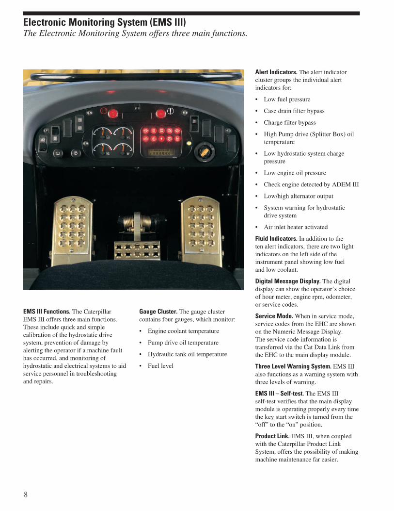
EMS III Functions. The CaterpillarEMS III offers three main functions.These include quick and simplecalibration of the hydrostatic drivesystem, prevention of damage byalerting the operator if a machine faulthas occurred, and monitoring ofhydrostatic and electrical systems to aidservice personnel in troubleshootingand repairs.
Gauge Cluster. The gauge clustercontains four gauges, which monitor:
• Engine coolant temperature
• Pump drive oil temperature
• Hydraulic tank oil temperature
• Fuel level
Alert Indicators. The alert indicatorcluster groups the individual alertindicators for:
• Low fuel pressure
• Case drain filter bypass
• Charge filter bypass
• High Pump drive (Splitter Box) oiltemperature
• Low hydrostatic system chargepressure
• Low engine oil pressure
• Check engine detected by ADEM III
• Low/high alternator output
• System warning for hydrostaticdrive system
• Air inlet heater activated
Fluid Indicators. In addition to theten alert indicators, there are two lightindicators on the left side of theinstrument panel showing low fueland low coolant.
Digital Message Display. The digitaldisplay can show the operator’s choiceof hour meter, engine rpm, odometer,or service codes.
Service Mode. When in service mode,service codes from the EHC are shownon the Numeric Message Display.The service code information istransferred via the Cat Data Link fromthe EHC to the main display module.
Three Level Warning System. EMS IIIalso functions as a warning system withthree levels of warning.
EMS III – Self-test. The EMS IIIself-test verifies that the main displaymodule is operating properly every timethe key start switch is turned from the“off” to the “on” position.
Product Link. EMS III, when coupledwith the Caterpillar Product LinkSystem, offers the possibility of makingmachine maintenance far easier.
8
Electronic Monitoring System (EMS III)The Electronic Monitoring System offers three main functions.
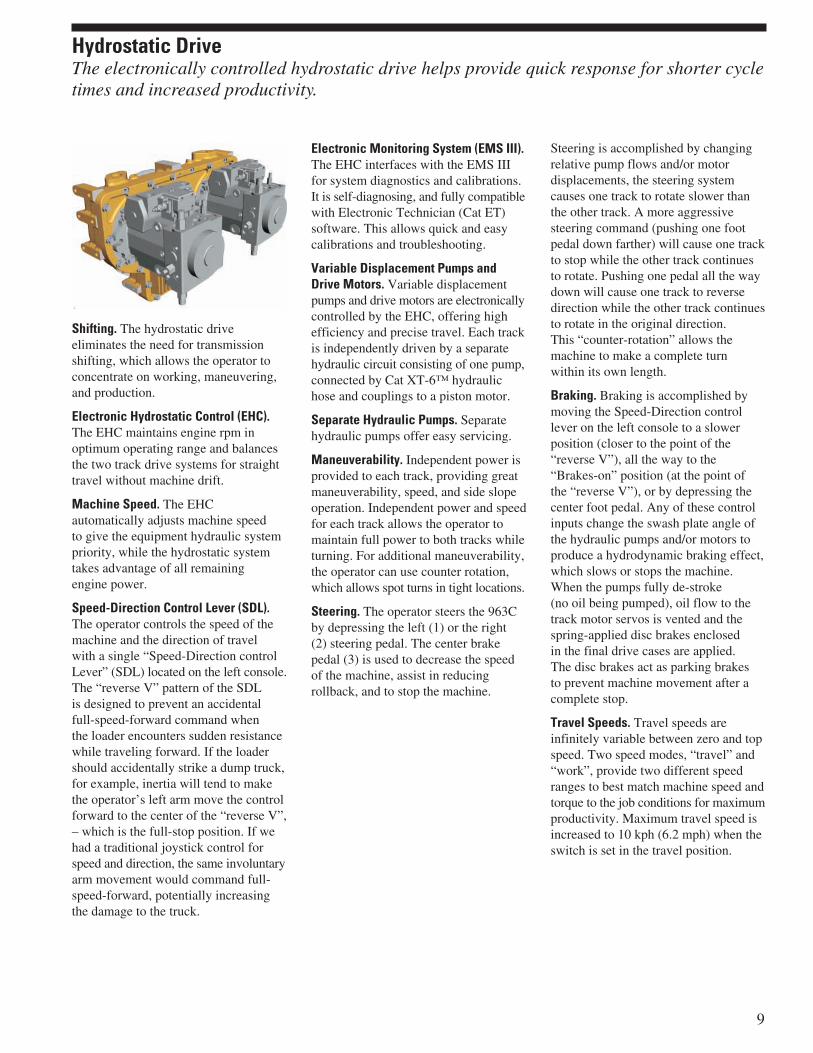
Shifting. The hydrostatic driveeliminates the need for transmissionshifting, which allows the operator toconcentrate on working, maneuvering,and production.
Electronic Hydrostatic Control (EHC).The EHC maintains engine rpm inoptimum operating range and balancesthe two track drive systems for straighttravel without machine drift.
Machine Speed. The EHCautomatically adjusts machine speedto give the equipment hydraulic systempriority, while the hydrostatic systemtakes advantage of all remainingengine power.
Speed-Direction Control Lever (SDL).The operator controls the speed of themachine and the direction of travelwith a single “Speed-Direction controlLever” (SDL) located on the left console.The “reverse V” pattern of the SDLis designed to prevent an accidentalfull-speed-forward command whenthe loader encounters sudden resistancewhile traveling forward. If the loadershould accidentally strike a dump truck,for example, inertia will tend to makethe operator’s left arm move the controlforward to the center of the “reverse V”,– which is the full-stop position. If wehad a traditional joystick control forspeed and direction, the same involuntaryarm movement would command full-speed-forward, potentially increasingthe damage to the truck.
Electronic Monitoring System (EMS III).The EHC interfaces with the EMS IIIfor system diagnostics and calibrations.It is self-diagnosing, and fully compatiblewith Electronic Technician (Cat ET)software. This allows quick and easycalibrations and troubleshooting.
Variable Displacement Pumps andDrive Motors. Variable displacementpumps and drive motors are electronicallycontrolled by the EHC, offering highefficiency and precise travel. Each trackis independently driven by a separatehydraulic circuit consisting of one pump,connected by Cat XT-6™ hydraulichose and couplings to a piston motor.
Separate Hydraulic Pumps. Separatehydraulic pumps offer easy servicing.
Maneuverability. Independent power isprovided to each track, providing greatmaneuverability, speed, and side slopeoperation. Independent power and speedfor each track allows the operator tomaintain full power to both tracks whileturning. For additional maneuverability,the operator can use counter rotation,which allows spot turns in tight locations.
Steering. The operator steers the 963Cby depressing the left (1) or the right(2) steering pedal. The center brakepedal (3) is used to decrease the speedof the machine, assist in reducingrollback, and to stop the machine.
Steering is accomplished by changingrelative pump flows and/or motordisplacements, the steering systemcauses one track to rotate slower thanthe other track. A more aggressivesteering command (pushing one footpedal down farther) will cause one trackto stop while the other track continuesto rotate. Pushing one pedal all the waydown will cause one track to reversedirection while the other track continuesto rotate in the original direction.This “counter-rotation” allows themachine to make a complete turnwithin its own length.
Braking. Braking is accomplished bymoving the Speed-Direction controllever on the left console to a slowerposition (closer to the point of the“reverse V”), all the way to the“Brakes-on” position (at the point ofthe “reverse V”), or by depressing thecenter foot pedal. Any of these controlinputs change the swash plate angle ofthe hydraulic pumps and/or motors toproduce a hydrodynamic braking effect,which slows or stops the machine.When the pumps fully de-stroke(no oil being pumped), oil flow to thetrack motor servos is vented and thespring-applied disc brakes enclosedin the final drive cases are applied.The disc brakes act as parking brakesto prevent machine movement after acomplete stop.
Travel Speeds. Travel speeds areinfinitely variable between zero and topspeed. Two speed modes, “travel” and“work”, provide two different speedranges to best match machine speed andtorque to the job conditions for maximumproductivity. Maximum travel speed isincreased to 10 kph (6.2 mph) when theswitch is set in the travel position.
9
Hydrostatic DriveThe electronically controlled hydrostatic drive helps provide quick response for shorter cycletimes and increased productivity.
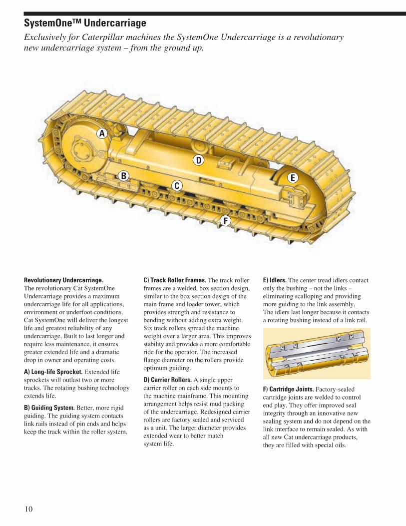
Revolutionary Undercarriage.The revolutionary Cat SystemOneUndercarriage provides a maximumundercarriage life for all applications,environment or underfoot conditions.Cat SystemOne will deliver the longestlife and greatest reliability of anyundercarriage. Built to last longer andrequire less maintenance, it ensuresgreater extended life and a dramaticdrop in owner and operating costs.
A) Long-life Sprocket. Extended lifesprockets will outlast two or moretracks. The rotating bushing technologyextends life.
B) Guiding System. Better, more rigidguiding. The guiding system contactslink rails instead of pin ends and helpskeep the track within the roller system.
C) Track Roller Frames. The track rollerframes are a welded, box section design,similar to the box section design of themain frame and loader tower, whichprovides strength and resistance tobending without adding extra weight.Six track rollers spread the machineweight over a larger area. This improvesstability and provides a more comfortableride for the operator. The increasedflange diameter on the rollers provideoptimum guiding.
D) Carrier Rollers. A single uppercarrier roller on each side mounts tothe machine mainframe. This mountingarrangement helps resist mud packingof the undercarriage. Redesigned carrierrollers are factory sealed and servicedas a unit. The larger diameter providesextended wear to better matchsystem life.
E) Idlers. The center tread idlers contactonly the bushing – not the links –eliminating scalloping and providingmore guiding to the link assembly.The idlers last longer because it contactsa rotating bushing instead of a link rail.
F) Cartridge Joints. Factory-sealedcartridge joints are welded to controlend play. They offer improved sealintegrity through an innovative newsealing system and do not depend on thelink interface to remain sealed. As withall new Cat undercarriage products,they are filled with special oils.
10
Exclusively for Caterpillar machines the SystemOne Undercarriage is a revolutionarynew undercarriage system – from the ground up.
SystemOne™ Undercarriage
A
BC
D
E
F

Track Shoes. Several track shoe typestaylor your machine for work in allunderfoot conditions.
Extreme Service Shoes.
• Work best in moderate to highimpact conditions.
• Recommended for applicationswhere the links outlast the shoes.
• More hardened wear material thanmoderate service track shoes.
Moderate Service Shoes.
• Work best in low to mediumabrasion conditions and low tomoderate impact conditions.
• All-purpose shoes recommendedfor any general application.
• Provides good penetration andtraction and resist wear and bending.
Multi-Grouser Shoes.
• Work best in applications thatrequire less penetration and traction.
• Recommended for applications thatrequire better turning capability andless ground disturbance.
• Feature two or three short grousersinstead of one tall grouser.
Trapezoidal Center Hole Shoes.
• Work best in applications wherepacking causes the track to tighten,accelerating pin and bushing wear.
• Recommended for applications withlarge amounts of debris that tend topack in the track.
• Reduces extrudable packingbetween the shoe and the bushingsince they allow the sprocket topunch out dirt and debris.
Oscillating Track Roller Frame.The oscillating track roller frame designdecreases ground induced impact loadsto the machine, increases machinestability on rough terrain, and providesa smoother, more comfortable ride forthe operator.
Pivot Shaft. Steel pivot shafts attach therear ends of the track roller frames tothe loader mainframe and carry mostof the weight. The pivot shafts transferground induced shock loads fromthe track roller frames to the loadermainframe rather than through thefinal drives. The result is longer finaldrive life.
Track Adjuster. The track adjusterand mechanical recoil system usesa large recoil spring and grease filledadjustment cylinder, which allowsthe idler to move forward and backto maintain proper track tension asit absorbs undercarriage shock loads.
Equalizer Bar. The equalizer bar ispinned in its center to the machinemainframe and at the ends to each trackroller frame. This allows the forwardends of the track roller frames to oscillate,or move vertically, to keep more trackon the ground in uneven underfootconditions. The equalizer bar alsoprovides a more stable work platformfor the operator, who will be comfortableworking at faster speeds for increasedproductivity.
Swing-Link Idler. Permits horizontalidler movement, absorbing shock loadsand maintaining proper track tension,while eliminating the need for shimsand wear strips. The removal of wearstrips eliminates a point of service andmaintenance. Cat idler provide superiorstructural support.
11
1 2
3 4
(1) Extreme Service (2) Moderate Service (3) Multi-Grouser (4) Trapezoidal Center

Mainframe and Loader Tower.The mainframe and loader tower is asingle, welded fabrication with castingsand forgings incorporated at points ofhigh stress to distribute those stressesover wide areas for a long structural life.
Design. Strong box-section mainframedesign, with continuous, deep-penetrationwelds resist twisting loads to protectcomponents from excessive wear ordamage without adding extra weight tothe machine. The frame rails consist oftwo box sections, which are joined atthe rear by a box section cross member.Mounting points for the final drives,pivot shafts, and operator’s platform areintegrated into each mainframe side rail.
Four-Plate Loader Tower. The four-plate loader tower is integral with thebasic mainframe. The loader towerdistributes forces evenly from the liftarms to the mainframe, which eliminatestwisting for maximum structuraldurability. The loader tower providessolid mounting points for lift arms,lift cylinders, and Z-Bar tilt cylinder.
Castings. Steel castings (shown in red)are used in areas of high stressconcentration. Large radius curvesdissipate stresses that could causefatigue and cracking.
Steel Frame. Fatigue resistant steelframe sections along with castingsprovide flexibility, durability andexcellent resistance to impact loads.
Durability. Structures are designed toprovide durability and extended servicelife to support multiple rebuilds.
Straddle Mounting. Straddle mountingsupports all lift arm pivot points on bothends of the pin eliminating twistingforces and enhancing structural durability.
Z-Bar Linkage. Breakout force isexceptionally high due to mechanicaladvantage of Z-bar linkage design, andhydraulic pressure applied to the headend of the tilt cylinder. Using a singletilt cylinder and linkage provides theoperator a better view of the work area,bucket, and cutting edge.
Sealed Loader Linkage. The 963Clinkage has fewer grease points comparedto other linkage designs because everypin joint is sealed to keep grease inand dirt out. Fewer grease points andsealed pins means less downtime formaintenance allowing more workinghours between servicing.
Simultaneous Lift and Dump.Simultaneous lift and dump for fasttruck loading and smooth grading, andthe ability to meter material from bucket.
Lift Kickout. Automatic, adjustablemagnetic lift kickout and bucketpositioner allow the operator toconcentrate on positioning the machinerather than the bucket. This results inhigher efficiency for greater productivity.
Return-to-Dig. The “Return-to-dig”switch assembly is located on the tiltcylinder and rod. It sets the angle thebucket will return to after it is dumped,when the bucket lever is placed in theTilt-back – hold position.
Lift Arms. The two arms are welded intoa single unit, using a weld-fabricatedcross-tube. The fabricated cross-tubeand tilt lever, use forging at high stresspoints to spread the loads for long life.
12
StructureThe box-section mainframe is designed to handle heavy loads, while Z-Bar linkagemaximizes breakout force, while distributing stress loads to the mainframe.
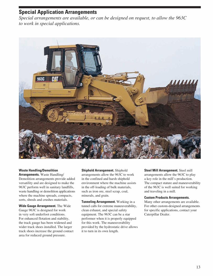
Waste Handling/DemolitionArrangements. Waste Handling/Demolition arrangements provide addedversatility and are designed to make the963C perform well in sanitary landfills,waste handling or demolition applicationswhere the machine spreads, compacts,sorts, shreds and crushes materials.
Wide Gauge Arrangement. The WideGauge 963C is designed for workin very soft underfoot conditions.For enhanced flotation and stability,the track gauge has been widened andwider track shoes installed. The largertrack shoes increase the ground contactarea for reduced ground pressure.
Shiphold Arrangement. Shipholdarrangements allow the 963C to workin the confined and harsh shipholdenvironment where the machine assistsin the off-loading of bulk materials,such as iron ore, steel scrap, coal,minerals, and grain.
Tunneling Arrangement. Working in atunnel calls for extreme maneuverability,clean exhaust, and special safetyequipment. The 963C can be a starperformer when it is properly equippedfor this work. The maneuverabilityprovided by the hydrostatic drive allowsit to turn in its own length.
Steel Mill Arrangement. Steel millarrangements allow the 963C to playa key role in the mill’s production.The compact stature and maneuverabilityof the 963C is well suited for workingand traveling in a mill.
Custom Products Arrangements.Many other arrangements are available.For other custom-designed arrangementsfor specific applications, contact yourCaterpillar Dealer.
13
Special Application ArrangementsSpecial arrangements are available, or can be designed on request, to allow the 963Cto work in special applications.

Versatility. The large variety of tasks anoperator can perform with the standardmachine and Work Tools has lead to theCaterpillar Track Loader’s reputationfor versatility.
General Purpose Bucket. The GeneralPurpose (GP) bucket is designed forexcellent loadability and long life in abroad range of applications such as hardbank excavating, stripping and stockpileloading. High-strength, low-alloysteel helps the bucket resist dentsand abrasions.
General Purpose Landfill Bucket.With the integrated trash-rack, theGeneral Purpose Landfill (GP Landfill)bucket becomes ideal for digging,loading and carrying as well as dozingand spreading material at landfills,or loading refuse at a transfer station.
Multi-Purpose Bucket. The Multi-Purpose (MP) bucket combines theperformances of a standard bucket,dozer blade and clamp. The bucketis designed for a broad range ofapplications, such as loading, stripping,clearing, bulldozing, picking up debris,and fine grading. The bucket clampshydraulically to grip logs or handleother tough-to-grasp materials.
Extreme-Service Multi-Purpose Bucket.The Extreme-Service Multi-Purpose(MP ES) has the same shape and loadcapacity as the Multi-Purpose bucket.The reinforced hinges, thicker side-platesand reinforced spill-plate make thebucket suitable for tougher applications.
Multi-Purpose Landfill Bucket.The Landfill Multi-Purpose (MP Landfill)bucket combines the versatility ofa Multi-Purpose bucket with theperformance of a Landfill design.Constructed with a trash-rack forincreased capacity, extra strengthand better load retention.
Refuse Bucket. The Refuse bucketfeatures high capacity and is designed foruse at transfer stations, recycling plantsand waste-to-energy plants. Increasedheight permits bucket to doze largeamounts of trash into hopper or for usein load and carry applications. Visibilitywindows aid operator efficiency.
Pallet Forks. When used with a quickcoupler, Pallet Forks increase theversatility of the machine. They areideal for handling a variety of materials.
K Series™ Tooth System. The K Seriestooth system provides longer tip andadapter life, faster cycle time with greaterbucket fills and reduced machine strain.
Longer Tooth Life. Tips are installedwith a slight twist and secured with aone-piece retainer, providing less tipmovement and nose wear.
Stable System Geometry. Opposing,sloped rails on the adapter providefull length stabilization with minimalmovement. The tip bears directly on theend of the adapter nose to absorb thrustloads, leading to better tip retention anda longer adapter life.
Easy Installation and Removal.Opposing sloped side rails and flankskeep the tip on the nose as the retaineris being installed and removed.The one-piece vertical retainer requireslow force and no special tools, allowingfaster and easier removal and installation,amounting to less machine down timefor tip changes.
14
A variety of attachments and Ground Engaging Tools (GET) are available to maximizeperformance in any application.
Work Tools and GET

Sharper Digging Profile. Lower heightat the front and the back of the noseprovides a sharper profile. This providesmore production, less machine strainand lower cost of machine operation.
Reversible Tips. Each tip ear has aretainer groove with a locking recess.Tips can be run in one direction,then “flipped,” or reversed, to get themaximum use of wear material fromthe tip.
Ripper-Scarifier. The ripper-scarifieradds extra versatility to expand theapplication of the machine. Hinged-type,with three shanks, beam mounted withtwo pins pressed into each side of themainframe. Raised and lowered withtwo wide-mounted cylinders. Six-pinlinkage requires no lubrication.
Additional Work Tools. Beyond the GPand MP buckets and the Ripper-scarifieryour Cat dealer offers: Material HandlingArm, Side-Dump Buckets, Loader andClamp Rakes, Forks, and Horizontal PinLock Quick Couplers.
Bucket Protection Options. Caterpillaroffers several types of adapters, tips,and cutting edges, which increasebucket life and maximize performance.
(1) Bolt-on adapters, tips, and bolt-onreversible edge segments provide aclean working floor and increasebucket capacity. Heavy-duty segmentsare available with 62 percent morewear material than standard segments.
(2) Bolt-on, 2-strap adapters, and tips,including corner adapters, offerexcellent penetration.
(3) Bolt-on, reversible, cutting edgesare ideal when penetration is not aconsideration, such as in clean-upwork or stockpiling applications.
(4) Weld-on, top-strap adapters are alsoavailable with a GP bucket. They areflush-mounted with the bottom ofthe cutting edge to provide a smoothbucket bottom and unrutted worksurface. These adapters can be usedwith any of the tip options (not witha bolt-on protection system).
Tip Options. Caterpillar GET offers avariety of tips to better accommodateyour needs in any working environment,whether that is high impact or general-purpose applications.
These and other GET options areavailable from your Caterpillar Dealer.
Short Tips. Short tips are extremelystrong and are for use in high impactand pry-out work such as rock.
General Duty Tips. General duty tipsare for use in most general applicationswhere breakage is not a concern.
Heavy-duty Tips. Heavy-duty tips arefor use in general loading and excavationwork. Thirty-six percent more wearmaterial than on the standard tip.Provides increased strength, extendedservice life, and low cost-per-hour.
15
Reduced Maintenance. The 963C hasmany service features, including:
• Caterpillar Extended Life Coolantfor extended change intervals.
• Sealed electrical connectors lock outdust and moisture.
• Caterpillar XT™ hydraulic hose,in medium and high-pressure circuits,provide high abrasion resistance andfar exceed industry standards.
• O-Ring Face Seals (ORFS) hydrauliccouplings help eliminate fluid leaks,provide positive seals, and arereusable for lower operating costs.
• Removable cab floor panels allowaccess to the engine, and hystat andimplement pumps.
• Extended change intervals forengine and hydraulic/hystat oil.
• Scheduled Oil Sampling FluidsAnalysis helps avoid unnecessarydowntime. S•O•SSM fluid taps makeoil sampling easier.
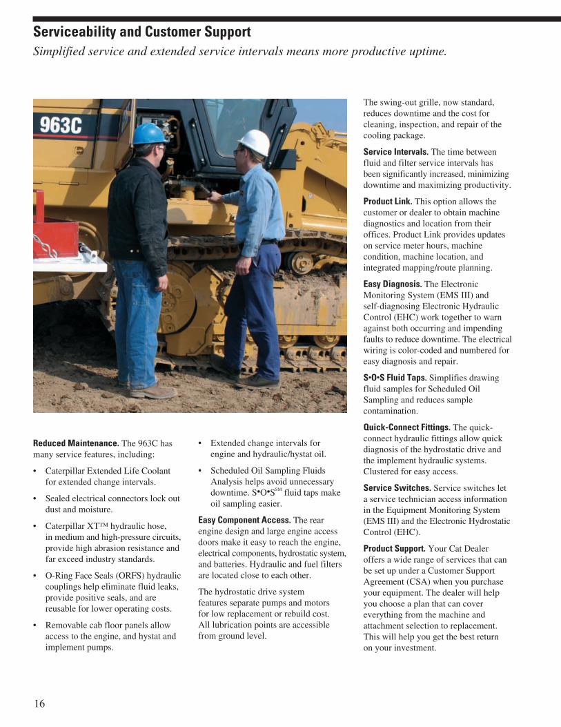
Easy Component Access. The rearengine design and large engine accessdoors make it easy to reach the engine,electrical components, hydrostatic system,and batteries. Hydraulic and fuel filtersare located close to each other.
The hydrostatic drive systemfeatures separate pumps and motorsfor low replacement or rebuild cost.All lubrication points are accessiblefrom ground level.
The swing-out grille, now standard,reduces downtime and the cost forcleaning, inspection, and repair of thecooling package.
Service Intervals. The time betweenfluid and filter service intervals hasbeen significantly increased, minimizingdowntime and maximizing productivity.
Product Link. This option allows thecustomer or dealer to obtain machinediagnostics and location from theiroffices. Product Link provides updateson service meter hours, machinecondition, machine location, andintegrated mapping/route planning.
Easy Diagnosis. The ElectronicMonitoring System (EMS III) andself-diagnosing Electronic HydraulicControl (EHC) work together to warnagainst both occurring and impendingfaults to reduce downtime. The electricalwiring is color-coded and numbered foreasy diagnosis and repair.
S•O•S Fluid Taps. Simplifies drawingfluid samples for Scheduled OilSampling and reduces samplecontamination.
Quick-Connect Fittings. The quick-connect hydraulic fittings allow quickdiagnosis of the hydrostatic drive andthe implement hydraulic systems.Clustered for easy access.
Service Switches. Service switches leta service technician access informationin the Equipment Monitoring System(EMS III) and the Electronic HydrostaticControl (EHC).
Product Support. Your Cat Dealeroffers a wide range of services that canbe set up under a Customer SupportAgreement (CSA) when you purchaseyour equipment. The dealer will helpyou choose a plan that can covereverything from the machine andattachment selection to replacement.This will help you get the best returnon your investment.
16
Simplified service and extended service intervals means more productive uptime.
Serviceability and Customer Support
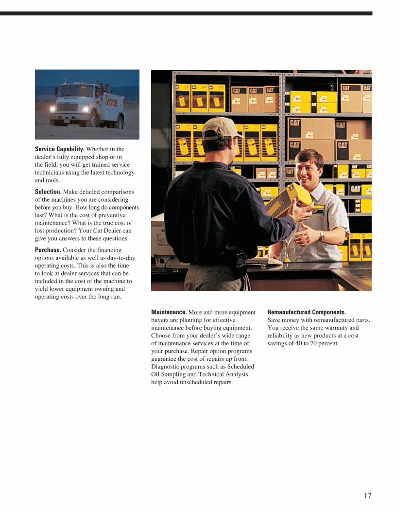
Service Capability. Whether in thedealer’s fully equipped shop or inthe field, you will get trained servicetechnicians using the latest technologyand tools.
Selection. Make detailed comparisonsof the machines you are consideringbefore you buy. How long do componentslast? What is the cost of preventivemaintenance? What is the true cost oflost production? Your Cat Dealer cangive you answers to these questions.
Purchase. Consider the financingoptions available as well as day-to-dayoperating costs. This is also the timeto look at dealer services that can beincluded in the cost of the machine toyield lower equipment owning andoperating costs over the long run.
Maintenance. More and more equipmentbuyers are planning for effectivemaintenance before buying equipment.Choose from your dealer’s wide rangeof maintenance services at the time ofyour purchase. Repair option programsguarantee the cost of repairs up front.Diagnostic programs such as ScheduledOil Sampling and Technical Analysishelp avoid unscheduled repairs.
Remanufactured Components.Save money with remanufactured parts.You receive the same warranty andreliability as new products at a costsavings of 40 to 70 percent.
17

18 963C Track Loader specifications
Drive System
Type Hydrostatic drive withinfinite machine speedsup to 10 km/h (6.2 mph)
Drive Pump Two,variable-displacement,slipper-type axialpiston pumps
Track Motor Two,variable-displacement,bent axis piston motors
Relief Valve Setting 44 000 kPa 6,380 psi
Hydraulic System – Equipment
Type VaneOutput 215 L/min 56.8 gal/minMain Relief Valve Setting 21 000 kPa 3,045 psiLift Cylinders – Bore 139.7 mm 5.5 inLift Cylinders – Stroke 837 mm 32.9 inTilt Cylinders – Bore 165.1 mm 6.5 inTilt Cylinders – Stroke 623.6 mm 24.6 in
Hydraulic System – Pilot
Output – Maximum 12 L/min 3.2 gal/minRelief Valve Setting 2850 kPa 413 psiCycle Time – Raise 6.6 SecondsCycle Time – Dump 1.3 SecondsCycle Time – Lower, Empty, 2.1 SecondsFloat Down
• With simultaneous raise and dump, dump time is includedin raise time.
Service Refill Capacities
Fuel Tank 315 L 83.2 galCooling System 30.5 L 8 galCrankcase (with Filter) 28 L 7.4 galFinal Drives (each) 15 L 4 galHydraulic System (Equipment, 160 L 42.3 galPower Train and Tank)Hydraulic Tank 68.1 L 18 galPump Drive Box 3.8 L 1 galPivot Shaft 2.2 L 0.5 gal
Engine
Engine Model Cat 3126B ATAACNet Flywheel Power 118 kW 158 hpNet Power – Caterpillar 118 kW 158 hpNet Power – ISO 9249 118 kW 158 hpNet Power – EEC 80/1269 118 kW 158 hpBore 110 mm 4.33 inStroke 127 mm 5 inDisplacement 7.2 L 442 in3
• Engine ratings at 2,000 rpm.
• Meets the U.S. EPA Tier 2, European Union Stage 2 andJapan MOC exhaust emission regulations.
• Net power advertised is the power available at the flywheelwhen the engine is equipped with fan, air cleaner, muffler,and alternator.
• No derating required up to 4500 m (14,715 ft) altitude.
Undercarriage
Track Shoe Type Double Grouser ExtremeService
Track Shoe Width – Standard 550 mm 21.6 inTrack Shoe Width – Optional 450 mm 17.7 inTrack Rollers – Each Side 6Number of Shoes – Each Side 37Track on Ground 2458 mm 97 inGround Contact Area – 2.7 m2 4,184 in2
Standard ShoeGround Contact Area – 2.2 m2 3,425 in2
Optional ShoeGround Pressure – 72.4 kPa 10.5 psiStandard ShoeGround Pressure – 88.5 kPa 12.8 psiOptional ShoeGrouser Height – 42.5 mm 1.67 inDouble GrouserTrack Gauge 1850 mm 72.8 in
• Super LGP arrangement available for lower ground pressureapplications.
• Ground pressure is calculated using operating weightof machine with GP bucket, teeth and segments.
19963C Track Loader specifications
Ripper Specifications
Type RadialNumber of Pockets 3Overall Width/Beam 1951 mm 76.8 inShank Cross Section 58 x 139 mm 2.3 x 5.5 inGround Clearance 595 mm 23.4 inPenetration 295 mm 11.6 inRipping Width 1836 mm 72.3 inCylinders – Bore 114.3 mm 4.5 inCylinders – Stroke 289 mm 11.4 inAddition to Machine 610 mm 24 inLength due to Ripper(in Transportation Position)
Standards
ROPS/FOPS ROPS/FOPSBrakes BrakesCab Cab
• ROPS (Rollover Protective Structure) offered by Caterpillarfor the machine meets ROPS criteria SAE J397 OCT95,SAE J1040 MAY94, ISO 3164:1995, ISO 3471:1994.
• FOPS (Falling Object Protective Structure) meetsSAE J231 JAN81, ISO 3449:1992 Level II.
• Brakes meet the standard SAE J1026 APR90, ISO 10265:1998.
• The operator sound exposure Leq (equivalent soundpressure level) measured according to the work cycleprocedures specified in ANSI/SAE J1166 MAY90 is 82 dB(A),for cab offered by Caterpillar, when properly installed andmaintained and tested with the doors and windows closed.
• Hearing protection may be needed when operating withan open operator station and cab (when not properlymaintained or doors/windows open) for extended periodsor in a noisy environment.
• The exterior sound pressure level for the standard machinemeasured at a distance of 15 meters (49.2 ft) according tothe test procedures specified in SAE J88 APR95, mid-gear-moving operation, is 77 dB(A).
Electrical System
Type 24V DCBattery Capacity 750 CCABattery Voltage 12Battery Quantity 2Alternator 70 amp, Heavy-Duty
Brushless
Weights
Operating Weight 19 589 kg 43,096 lbShipping Weight – 17 692 kg 38,923 lbwithout Bucket
• Operating Weight: Includes coolant, lubricants, 100% fueltank, ROPS/FOPS cab, General Purpose Bucket with longbolt-on teeth and segments and 75 kg/165 lb operator.
• Shipping Weight: Includes coolant, lubricants, 10% fuel tank,ROPS/FOPS cab and no bucket.
Buckets
Capacity – General Purpose 2.45 m3 3.2 yd3
Capacity – Multi-Purpose 2 m3 2.6 yd3
Bucket Width – General Purpose 2550 mm 100.3 inBucket Width – Multi-Purpose 2434 mm 99.4 in
• Bucket capacities are with long bolt-on teeth and segments.
• Bucket widths are based on a bare bucket.
Operating Specifications
Max. Travel Speed 10 km/h 6.2 mph

20 963C Track Loader specifications
Rated bucket capacity †(Nominal heaped)
Struck capacity †
Bucket width – overall
Bucket weight
Dump clearance at full lift and 45° discharge †
Reach at 45° discharge angleand 2133 mm (84 in) clearance †
Reach at full lift and 45° discharge
Digging depth †
Maximum rollback at ground
Maximum rollback at carry position
Bucket height in carry position
Overall machine lengthBucket level on ground
Overall machine height with bucket at full raise
Static tipping load
Breakout force – with tilt cylindersBucket level at ground
Operating weight*
2.3 2.45 2.45 2.3 2.6 2.7 2.73.0 3.2 3.2 3.0 3.4 3.5 3.5
2.0 2.14 2.14 2.0— — —
2.6 2.8 2.8 2.6
2498 2550 2539 2583 2482 2573 249898.3 100.3 99.9 101.7 97.7 101.3 98.3
1274 1610 1492 1375 2026 2294 22262,803 3,542 3,282 3,025 4,467 5,057 4,907
3148 2936 3060 2948— — —
124 116 120 116
1786 1966 1840 2010— — —
70.3 77.4 72.4 79
1161 1341 1215 1385— — —
45 52 48 55
87.2 142 117.2/122.2 87.2— — —
3 6 5 3
43° 43° 43° 43° — — —
51° 51° 51° 51° — — —
474 474 474 474— — —
19 19 19 19
6350 6625 6448 6657— — —
250 261 254 262
5319 5319 5319 5319 5881 5881 5881209 209 209 209 232 232 232
14 080 13 596 13 774 13 982 12 618 12 310 12 33830,976 29,911 30,303 30,760 27,818 27,139 27,201
191.7 172.6 173.4 186.7— — —
43,133 38,835 39,015 42,008
19 253 19 589 19 473 19 354 19 489 19 757 19 68942,327 43,096 42,841 42,579 42,966 43,557 43,407
m3
yd3
m3
yd3
mmin
kglb
mmin
mmin
mmin
mmin
Deg
Deg
mmin
mmin
mmin
kglb
kNlb
kglb
General purposebucket
Landfillbucket
Bare
Bolt-onteeth &
segments
Bolt-onteeth &
segments
Bolt-oncuttingedge
Flushmounted,weld-on
adapters &tips Bare
Bolt-oncuttingedge
* Includes coolant, lubricants, full fuel tank, ROPS cab, bucket and 75 kg/165 lb operator.† Specifications and ratings conform to all applicable standards recommended by the Society of Automotive Engineers.
SAE Standard J732 JUN92 and SAE Standard J742 FEB85 govern loader ratings.
ROPS canopy only (cab removed) -350 kg -772 lb -418 kg -922 lb
Ripper with 3 shanks (bumper removed) +215 kg +474 lb +339 kg +747 lb
Rear bumper (removal) -582 kg -1,283 lb -1291 kg -2,846 lb
Change InOperating Weight
Change In StaticTipping Load
NOTE: Machine stability can be affected by the addition of other attachments. Add or subtract to/from machine operating weight and statictipping load.
Operating Specifications

21963C Track Loader specifications
Rated bucket capacity †(Nominal heaped)
Struck capacity †
Bucket width – overall
Bucket weight
Dump clearance at full lift and 45° discharge †
Reach at 45° discharge angleand 2133 mm (84 in) clearance †
Reach at full lift and 45° discharge
Digging depth †
Maximum rollback at ground
Maximum rollback at carry position
Bucket height in carry position
Overall machine lengthBucket level on ground
Overall machine height with bucket at full raise
Static tipping load
Breakout force – with tilt cylindersBucket level at ground
Operating weight*
1.9 2.0 2.0 1.9 2.0 2.02.5 2.6 2.6 2.5 2.6 2.6
1.58 1.72 1.72 1.58 1.72 1.722.1 2.2 2.2 2.1 2.2 2.2
2482 2573 2498 2482 2573 249897.7 101.3 98.3 97.7 101.3 98.3
1764 2032 1964 2032 2300 22323,889 4,480 4,330 4,480 5,071 4,921
2977 2780 2881— — —
117 109 113
1592 1725 1638— — —
62.7 68 64.5
1045 1178 1091— — —
41 46 43
165 204 195— — —
7 8 8
46° 46° 46° — — —
52° 52° 52° — — —
541 541 541— — —
21 21 21
6450 6551 6685— — —
264 258 263
5353 5353 5353 5353 5353 5353211 211 211 211 211 211
12 880 12 572 12 600 12 612 12 304 12 33228,396 27,716 27,778 27,805 27,126 27,187
178.6 167.6 176.5— — —
40,185 37,710 39,713
19 227 19 495 19 427 19 495 19 763 19 69542,388 42,979 42,829 42,979 43,570 43,420
m3
yd3
m3
yd3
mmin
kglb
mmin
mmin
mmin
mmin
Deg
Deg
mmin
mmin
mmin
kglb
kNlb
kglb
Multi-purposebucket
MP extremeservice bucket
Bare
Bolt-onteeth &
segments
Bolt-onteeth &
segments
Bolt-oncuttingedge Bare
Bolt-oncuttingedge
* Includes coolant, lubricants, full fuel tank, ROPS cab, bucket and 75 kg/165 lb operator.† Specifications and ratings conform to all applicable standards recommended by the Society of Automotive Engineers.
SAE Standard J732 JUN92 and SAE Standard J742 FEB85 govern loader ratings.
Operating Specifications

22 963C Track Loader specifications
System One1 Overall machine width without bucket:
with standard tracks – 550 mm (21.7 in shoes) 2400 mm (94.5 in)
with narrow tracks – 450 mm (17.7 in shoes) 2200 mm (86.6 in)
2 Ground clearance from face of shoe 402.5 mm (15.8 in)
Grading angle 68°
3 Machine height to top of cab 3396 mm (133.7 in)
4 Length to front of track 4615 mm (181.7 in)
5 Overall machine length �6 Carry position approach angle 15°
7 Digging depth �8 Maximum rollback at ground �9 Maximum rollback at carry position �10 Bucket height in carry position �11 Reach at full lift height �12 S.A.E. specified dump angle 45° (46° max.)
13 Maximum rollback, fully raised 59°
14 Dump clearance at full lift height and 45° discharge �15 Height to bucket hinge pin 3938 mm (155 in)
16 Overall machine height, bucket fully raised �17 Height to top of seat with headrest 2849.5 mm (112.2 in)
18 Height to top of stack 2774 mm (109.2 in)
� Dimensions vary with bucket. Refer to Operating Specifications chart.
DimensionsAll dimensions are subject to change without notice.
16
15
14
7
9
8
1211
13
641
5
183
17
2 10

23963C Track Loader specifications
Standard EquipmentStandard equipment may vary. Consult your Caterpillar dealer for details.
OPERATOR ENVIRONMENTAir conditionerAdjustable steering pedalArmrests, adjustableAshtray, lighter (24-volt)Cab, pressurized and sound suppressed
tinted glass, (ROPS/FOPS)Coat hookControl, single lever, pilot operated
for implement hydraulicsCup holderHeater and defrosterHornInstrumentation, gauges
Engine coolant temperatureFuel levelHydraulic oil temperaturePump drive gear box oil temperature
Instrumentation, alert indicatorsAir inlet temperatureCase drain filter bypassCharge filter bypassCharge oil pressureCheck engineElectrical charging (too high/too low)Engine oil pressureFuel pressureHydrostatic drive systemPump drive (splitter box) oil temperature
Key startMirror, review (internal)Parking brake switch, brake-on indicator lightRadio ready, 24-volt to 12-volt converter,
speakers, antenna, mounting bracketSeat, (cloth) air-suspension with side-to-side isolatorSeat belt, retractable, 75 mm (3 in)Sound suppression, spectatorSpeed mode switch, (work-travel)Storage compartments under armrests
(lockable on right armrest)Wipers/washers (front and rear)
Intermittent front wiperFuel priming pump, electric
ELECTRICALAlarm, back-upAlternator (24-volt, 70-amp)Batteries, Cat premium, heavy-duty (900 CCA)Electronic Hydrostatic Control (EHC)Electronic Monitoring System (EMS III)Lights (2), ROPS mounted, forward facing (halogen)Lighting system (halogen) four lights, 2 forward, 2 rearPower outlet, 12-voltStarting motor, 24-volt electric
POWER TRAINAir inlet heaterDemand fanEngine, Cat 3126B HEUI diesel with ATAAC
turbocharged, with ADEM III ControllerFilters, air (radial seal)Fuel priming pump, electricAdjustable steering pedalPre-cleaner, air intakeRadiator guard, HD, perforated
UNDERCARRIAGESprocket guardsSprocket rims, segmentedTrack adjuster, hydraulicTrack guiding guards, end sectionTrack idlers, lifetime lubricatedTrack rollers (6), one upper carrier roller
lifetime lubricatedTrack shoes, 550 mm (21.6 in) SystemOne track shoes
OTHER STANDARD EQUIPMENTBucket positioner, automaticBumper, rearCoolant, extended lifeCooler, hydraulic oilCrankcase guard, fullHitch, front retrievalEngine enclosure, lockable doorsLift kickout, automaticO-ring face seal couplingsS•O•S valvesVandalism protection – fuel tank cap with padlock,
three padlocks for front service doors and radiator capaccess door
XT Hoses

24 963C Track Loader specifications
Optional EquipmentOptional equipment may vary. Consult your Caterpillar dealer for details.
Counterweights – 3 arrangementsLightMediumHeavy
Drawbar hitchGuards:
Cab/canopy lightsIdlerLift cylindersSeal protection – final drive, pivot shaft, and idler sealsTrack roller
Product linkRipper/scarifier, three ripper shanks (bumper removed)Starting aids:
Batteries, Cat premium, heavy-duty (900 CCA)Engine coolant heater, 120- or 220-volt
SystemOne™ Undercarriage:Track, 560 mm (22 in) DBL GR (37 SEC)Track, 450 mm (17.7 in) DBL GR (37 SEC)Track, 450 mm (17.7 in) DBL GR, ES, w/center hole (37 SEC)Track, 560 mm (22 in) DBL GR, ES (37 SEC)Track, 800 mm (31.5 in) DBL GR (37 SEC)Track, 450 mm (17.7 in) DBL GR, w/center hole (37 SEC)
Antifreeze for temperatures between –37° C (–34° F) and –50° C (–58° F)
Anti-theft, Machine Security System (MSS)Buckets:
General Purpose 2.3 m3 (3 yd3)General Purpose with weld-on flush-mounted adapters
2.3 m3 (3 yd3)Multi-purpose 1.5 m3 (2 yd3)
Bucket cutting edge, reversible, with end bits, sharpened, bolt-on, for GP and MP buckets
Bucket edge segments, bolt-on, for GP and MP bucketsStandardHeavy-duty (GP bucket only)
Bucket teeth, set of 8 bolt-on adapters and tips (K90 on GP bucket, K80 on MP bucket), includes corner adaptersGeneral duty, for GP bucketGeneral duty, for MP bucketHeavy Duty, for GP bucketHeavy Duty, for MP bucketPenetration, for GP bucketPenetration, for MP bucket
Bucket teeth weld on, flush mounted adapters, set of 8 includes corner teeth for GP and MP buckets
Bumper (removal)Canopy, ROPS (cab removed), includes rearview mirror,
2 forward facing lights, heater, vinyl seat and vandalismprotection consisting of cab vandalism package plusinstrument panel guard group with padlock
Controls (for equipment hydraulic system)Two-lever control3rd valve for use with lines for front and rear attachmentsDiverter valve for use when both front and rear lines
are required

963C Track Loader specifications 25
Notes

26
Notes

27
Notes

R
For more complete information on Cat products, dealer services, and industry solutions, visit us on the web at www.cat.com
© 2005 CaterpillarAll Rights Reserved
Printed in U.S.A.
Materials and specifications are subject to change without notice.Featured machines in photos may include additional equipment.
See your Caterpillar dealer for available options.
CAT, CATERPILLAR, their respective logos and “Caterpillar Yellow,”as well as corporate and product identity used herein, are
trademarks of Caterpillar and may not be used without permission.AEHQ5542-02 (10-05)
963C Track Loader


![DURABILITY OF FUEL PUMPS AND FUEL LEVEL ... … 664 [AVFL-15a]/AVFL... · DURABILITY OF FUEL PUMPS AND FUEL LEVEL ... Fuel pump soak data ... fuel pumps and fuel level senders were](https://img.dokumen.tips/doc/110x75/5b5fc9d67f8b9a51328e7dbf/durability-of-fuel-pumps-and-fuel-level-664-avfl-15aavfl-durability.jpg)