Embed Size (px)
Citation preview

Page 1 of 8
Operation & Maintenance Manuals
B-1 thru B-4 Condensing Boilers Specification Section # 23 5225
Project Name and Owner: Kelly Walsh High School 3500 East 12’th Street Natrona County School District # 1 Casper, Wyoming 82609 Architect: RB+B Architects Fort Collins, Colorado Mechanical Engineer: Engineering Design Associates Casper, Wyoming Mechanical Contractor: KK Mechanical Roy, Utah Sheet Metal Contractor: North Star HVAC West Haven, Utah Controls Contractor: Johnson Controls Casper, Wyoming Wholesale Distributor: Ferguson Enterprises Mills, Wyoming
Spec-Tech-Sales October 26, 2015 Integrated Boiler Room Solutions Commercial Technical Sales and Service For the Rocky Mountain Region 14652 West Vassar Drive
Lakewood, CO 80228 Colorado Phone 720-259-0718 Fax 720-204-2274
Wyoming Phone 307-222-7559 Fax 307-200-4068
Website: www.spec-tech-sales.com

Page 2 of 8
Patterson-Kelley MACH
Condensing Boilers Specified – Basis of Design
BASED UPON 100% FINAL CONSTRUCTION DRAWINGS & SPECIFICATIONS
100% Construction Drawings & Documents Issue Date May 12, 2014 Schedule Tag: B-1 thru B-4 Condensing Boilers Specification Section # 23 5225 Gas Fired Packaged Condensing Boilers Also Reference: Specification Section # 22 3000 Plumbing Equipment – Separate Submittal Package Specification Section # 23 5100 Vent Stacks – Separate Submittal Package -And- Specification Section # 01 1600 Product Requirements Specification Section # 23 0593 Testing Adjusting & Balancing Specification Section # 23 0800 Commissioning of HVAC System Specification Section # 23 0900 Building Automation System Specification Section # 23 2500 HVAC Water Treatment Specification Section # 23 2113 Hydronic Piping Specification Section # 23 2114 Hydronic Specialties Specification Section # 23 2123 Hydronic Pumps Scope Primarily Provided By Others - Listed For Coordination Purposes
Patterson-Kelley MACH Condensing Boilers – Scope of Supply
Tag: B-1 thru B-4 Heating Boilers – Condensing High Efficiency
Lot package consisting of (4) each Patterson-Kelley MACH model # C-4000 condensing premium
efficiency boiler assemblies each complete with superior high performance sectional multi-pass cast
aluminum heat exchanger assembly for condensing applications which does not require any push nipples
or gasket seals between sections. There are multiple water passes with a unique cast fire side pin design
that coupled with the stainless steel mesh burner and pre-mixed variable speed combustion blower
assembly helps promote optimum cross flow and counter flow heat exchange with exceptional fire side
and water side heat transfer turbulence for enhanced efficiency. 125-PSI design pressure ASME section
IV – H stamp, CSA third party certified 95% efficiency with up to 99% efficiency depending on return
water temperature and firing rate and certified to ANSI-Z21.13 with FM/CSD-1/GE-GAP/CSA4.9
compliance. Each boiler with 4,000-MBH sea level input and 3,800-MBH sea level output with
modulating 5:1 turndown burner – we will adjust the premixed variable speed combustion settings and
fuel / air ratio in accordance with site specific gas BTU content and calorific value for this category IV
forced draft positive pressure boiler to the maximum allowable boiler firebox rating at the time of startup.

Page 3 of 8
This to try to offset the typical 4% per 1000-feet elevation de-rate as much as possible and to achieve the
highest maximum MBH capacity output in accordance with factory combustion parameters at site
elevation of 5,150-feet with natural gas supplied with from 5” to 14” W.C. supply pressure range (must
confirm) at the inlet to the factory mounted, piped and wired boiler / burner gas train assembly. Each
boiler to include the advanced fully integrated ENVI on board combination burner management and
operating control platform assembly with multiple boiler staging and sequencing capabilities, hybrid boiler
plant operating capabilities, on-board or remote outside air reset schedule capabilities, on-board or
remote modulation capabilities, domestic water priority capabilities, boiler pump or motorized isolation
valve interface capabilities, motorized combustion air louver, damper or fan integration and prove
capabilities and complete with user friendly text based display of operating and error code indication with
date and time stamped lockout snapshot for enhanced ease of troubleshooting, BMS interface complete
with ModBus RS-485 protocol platform / interface capabilities as standard on each boiler complete with
optional (1) each BACnet wall mounted Protonode control panel gateway assembly –OR- Heat Timer
Multi-Mod Platinum with BACnet boiler staging / sequencing control panel assembly (must confirm
intent reference mechanical controls drawing # 6.M900 – building heating water system control diagram
and sequence of operation) as required to be interfaced to the (4) boilers if / as required for interface by
BAS controls contractor for project and boiler room specific sequence of operation and boiler interface to
meet the applicable boiler specific and project specific points list for remote read / write list requirements.
Flow rate as scheduled of 220-GPM of 35% multi-metal aluminum safe glycol with multi-metal inhibitor (provided by others) and water mix at approximately 6-TDH head loss through the boiler itself (must also add for boiler loop piping head loss). The Patterson-Kelley MACH C-4000 boiler overall flow rate range – offered for review and comparison at 20-degree F. high fire flow rate through the boiler of 345-GPM of water at approximately 13-TDH through the boiler itself (must also add for boiler loop piping head loss ) and 40-degree F. high fire flow rate through the boiler of 173-GPM of water at approximately 4-TDH through the boiler itself (must also add for boiler loop piping head loss) and if applicable with minimum variable volume flow through the boiler at low fire – 20% of rated capacity of 85-GPM of water at approximately 2-TDH through the boiler itself (must also add for boiler loop piping head loss). Please coordinate with the required boiler pumps - reference the applicable boiler pump schedule that lists BP-1 thru BP-4 boiler pumps (provided by others – not part of this scope of supply – listed for coordination purposes) being new WILO Stratos 3.0 x 3-40 self-contained ECM electronic commutated motor variable speed boiler pumps with 220-GPM @ 20-feet TDH with 35% propylene glycol (must be multi-metal aluminum safe propylene glycol with multi-metal inhibitor) IMPORTANT: The boiler pumps must have dedicated power supply NOT to be powered through the boiler circuit. The control strategy via the controls contractor to implement the boiler pump enable / disable with pump run-on via the Patterson-Kelley on board ENVI wiring terminal strip – must coordinate with the optional WILO IF interface module (provided by others with the boiler pumps) with startup and
commissioning coordination (between Spec-Tech-Sales for the boiler startup and commissioning
along with the WILO startup representative, the controls contractor and the test and balance contractor) to arrive at the desired boiler pump GPM and delta T. for peak efficiency and peak performance initiatives and for summer / winter operation.
Lot package to also include optional flow switch (1) per each boiler listed as FS-1 thru FS-4 and combustion air damper (1) per each boiler listed as CD-1 thru CD-4 and Emergency Kill Switch (1) per each boiler room entry door for CSD-1 code compliance – as listed per the Sequence of Operation on drawing # 6.M900 and detail # 2.2 Building Heating Water System Control.
IMPORTANT – Reference the Hot Water Sequence of Operation on drawing # 6.M900 points 1 thru 4.2.2 for overall B-1 thru B-4 boilers and BP-1 thru BP-4 boiler pumps – (boiler pumps provided by others – MUST CONFIRM if the BAS contractor scope of supply will be intending to monitor and drive variable speed boiler pump operation as per # 3.2.1 as this must be properly coordinated and integrated within Patterson-Kelley operational flow rate parameters), HWBT-1 heating system buffer tank and overall heating system operation, HX-1 and HX-2 with boiler side variable speed pumps and domestic side pump(s) for and HWT-1 and HWT-2 domestic water

Page 4 of 8
summer and winter system operation, and HWP-1 and HWP-2 building loop system pumps being variable speed – (system pumps provided by others) as listed per the Sequence of Operation on drawing # 6.M900 and the applicable Building Heating Water System Control diagrams.
Recommend a scope coverage coordination kickoff meeting for scope coverage, piping and controls integration purposes with the awarded mechanical contractor – KK Mechanical, the mechanical engineer – Engineering Design Associates, the awarded BAS controls contractor / DDC system integration_________ and the Natrona County School District personnel to sort out the applicable details and to address any potential problems or potential misinterpretation of scope coverage and capabilities.
Electrical requirements 480-volt / 60-Hz / 3-Phase power supply to each boiler and less than 20-AMP electrical disconnect which is provided by others.
Boiler supply and return connections = (1) each 4” Victaulic grooved supply and (1) each 4” Victaulic grooved return, gas train size for maximum allowable inlet gas pressure of 14” W.C. inlet gas pressure is 2”, boiler vent outlet size of 10” venting, boiler sealed combustion air intake size of 12” combustion air intake, total boiler approximate shipping weight = 1,900 #’s and total water content = 24-1/2-gallons total water content.
This scope of supply also to include for each boiler (1) each Patterson-Kelley motorized combustion air damper with end-switch (combustion air vent pipe and fittings provided by others – NOT part of this scope of supply) that is interfaced with the applicable ENVI wiring terminal strip boiler sequence of operation as specified and required.
Approximate boiler length per each boiler = 62-1/2” boiler cabinet footprint itself
Approximate boiler width per each boiler = 31-3/4” boiler cabinet footprint itself
Approximate boiler height per each boiler = 75-1/4” to top of boiler cabinet itself
Combustion air options being conventional room air through standard or integration with motorized louvers integration with induction fan if required / applicable for this project specific (4) each individually ducted / sealed combustion intake configuration to suit the specific boiler room application as required. Reference sealed / ducted combustion air routing with the detailed motorized combustion air dampers which are included (1) per each boiler in this scope of supply.
100-PSI pressure relief valve as per boiler schedule note # 9
Boiler lead / lag staging and sequencing rotation with firing rate control to be accomplished via the Patterson-Kelley ENVI on-board control assembly – to be daisy chained together between the (4) boilers interfaced back to the optional wall mounted Patterson-Kelley Protonode control panel gateway assembly for BAS system communication –OR- Heat Timer Multi-Mod Platinum with BACnet boiler staging / sequencing control panel assembly (must confirm intent reference mechanical controls drawing # 6.M900 – building heating water system control diagram and sequence of operation). This scope of supply to include an optional remote sensor with well modified depth for insertion into the applicable buffer tank assembly along with an optional outside air sensor assembly which may or may not be required because of summer / winter operation and any potential setback strategies reference the applicable HWBT-1 hot water system buffer tank assembly with MODIFIED tapping’s and assorted scope of supply although the applicable primary HWP-1 and HWP-2 system pumps to be enabled / disabled and variable speed drive controlled by others – NOT part of this scope of supply and / or direct control interface capabilities via the Patterson-Kelley ENVI control platform option although if the Heat Timer Multi-Mod-Platinum BACnet boiler staging / sequencing control panel assembly option is used said panel does have system pump outputs and prove capabilities.
This application is designed for sealed combustion air intake. Worth mentioning because sealed combustion air temperature could be coming in at design conditions of minus -13-degrees F. below zero or even colder especially in Casper, Wyoming with the wind considerations of which cold combustion air can dramatically impact combustion performance variables if the boiler design doesn’t offer some advantages to counter. The Patterson-Kelley MACH boilers for sealed combustion applications have the sealed combustion intake directly tied into the boiler cabinet on the opposite end of the burner intake as a design advantages for just such a consideration. This is an important distinction and benefit because the incoming combustion air is
Page 5 of 8
pre-heated as it travels across the condensing boiler heat exchanger / heat engine prior to entering the variable speed pre-mixed stainless steel radial fiber mesh premixed burner – a huge design advantage in helping to maintain ideal combustion efficiency and seasonal operating efficiency strategies. Cold air impacts combustion and efficiencies. The Patterson-Kelley MACH design compared with some other brands on the market the whereas the sealed combustion air intake directly into the burner intake box housing which allows for the potentially cold combustion air during design condition days at below zero which will vary O2% and CO2 % high fire and low fire settings for different incoming combustion air temperatures – example for the applicable (4) each MACH C-4000 boilers with 4000-MBH size it is an important consideration as CO2% is a critical component in the condensing dew point to capture the latent heat and achieve highest efficiencies – the higher the CO2% the better IE the Patterson-Kelley MACH natural gas settings = 9.2% CO2 at high fire and 9.1% at low fire very tight tolerances very tight control and O2 % at high fire = 4.8% and 5.0% at low fire – much LESS excess air, much tighter control of combustion to aid in capturing the latent heat / hitting the condensing dew point to achieve the desired efficiencies regardless of firing rate and regardless of incoming combustion air temperature because we pre-heat the combustion air on sealed combustion. Another benefit is that cold combustion air that travels across the Patterson-Kelley heat engine actually cools the block on the outside and coupled with the cold return water temperature inside the two combined really help promote condensing and premium efficiencies….) With non-preheated designs said cold combustion air is directly entering the important burner combustion process which is NOT pre-heated unless design provisions are made IE hot water coil or electric heater in the duct intake. Something like this does not immediately jump out in the initial comparative analysis review, but it is an important factor and as such I wanted to point it out accordingly. I do know that many forced draft burner manufacturers strongly recommend a pre-heater – via hot water coil or electric coil when using ducted fresh air intake to the burner in a cold weather climate this so as to not negatively impact performance.
The Patterson-Kelley MACH condensing boiler utilizes a superior stainless steel radial fiber mesh burner that is fully surrounded by the superior cast aluminum heat engine / heat exchanger on all sides – every bit of heat is put into the heating medium.
Reference boiler schedule note # 10 - Package to include (1) each applicable acid / condensate neutralization basin assembly sized and selected for the boiler and the application as detailed and required complete with sufficient limestone neutralizer for initial fill. This neutralization basin assembly is intended to pick up BOTH the condensate connection from the boiler and from the vent stack drain connection – reference applicable Schebler type AL29-4C stainless steel project specific venting package and scope of supply (any applicable high temperature condensate tubing, pipe & fittings along with any applicable floor drain / floor sink & / or condensate pump and its’ associated basin assembly if required / applicable – reference and coordinate with specific drawing detail which is all provided by others and not part of this scope of supply).
Reference written specification section # 23 2500 for chemical water treatment for mechanical systems – this scope of supply does NOT include an optional pot feeder with side stream filter assembly and multi-metal coupon retaining rack assembly along with any and all actual chemical treatment, and multi-metal aluminum safe glycol and / or cleaning and flushing is provided by others and not directly part of this scope of supply. This although it is referenced for coordination purposes between the chemical / water treatment contractor scope and the multi-metal inhibitor scope and the boiler manufacturer requirements proper system cleaning and flushing, PH level ranges, and water quality / solids level ranges as outlined. This for any and all inhibitors and multi-metal system wide requirement considerations whether straight water or multi-metal / aluminum safe glycol combination between system piping, termination units, wet rotor style pumps or pumps with separate pump seals and the new condensing boiler system wide installation. Because of the system piping and terminal units all tie in with the new high performance high efficiency boilers thus we have recommended as part of the water treatment scope by others a combination pot feeder and side stream filter assembly with the multi-metal coupon rack in each boiler room as part of the overall short and long term water treatment objectives and strategy. The side stream filter assembly coupled with boiler and system strainers will continually pull out large and fine particles keeping them out of critical orifices, pump

Page 6 of 8
seals, and the water side of the boilers heat exchanger to help ensure optimum heat transfer and long term operating efficiency and performance objectives.
NOTE: The Patterson-Kelley MACH C-4000 condensing boilers to include the Patterson-Kelley advanced fully integrated ENVI on board combination burner management and operating control platform assembly with multiple boiler staging and sequencing capabilities, hybrid boiler plant operating capabilities, on-board or remote outside air reset schedule capabilities, on-board or remote modulation capabilities, domestic water priority capabilities, boiler pump or motorized isolation valve interface capabilities, motorized combustion air louver, damper or fan integration and prove capabilities and complete with user friendly text based display of operating and error code indication with date and time stamped lockout snapshot for enhanced ease of troubleshooting, BMS interface complete with ModBus RS-485 protocol platform / interface capabilities as standard on each boiler complete with the required optional (1) each BACnet – BTL 3’rd party listed wall mounted Protonode control panel gateway assembly as required to be interfaced to the (4) boilers as required for interface by BAS controls contractor BACnet boiler staging / sequencing control panel assembly –OR- Heat Timer Multi-Mod Platinum with BACnet boiler staging / sequencing control panel assembly (must confirm intent reference mechanical controls drawing # 6.M900 – building heating water system control diagram and sequence of operation for project and boiler room specific sequence of operation and boiler interface to meet the applicable boiler specific and project specific points list for remote read / write list requirements. The onboard Patterson-Kelley ENVI control platform is a fully integrated advanced controller allowing for ease of user interface operation performing the following key functions summary:
Burner management / flame safeguard functions Boiler modulation, operational and high limit temperature control functions Boiler limit control interface functions with text based operational and lockout indication PID loop modulation and operational fine tuning capabilities Access to total boiler cycles / total run hours and breakout between low fire – mid fire and high fire run hours Boiler pump control – domestic priority pump or 3-way diverting valve control Multiple indirect domestic water heating control capabilities Combustion air or vent side fan or damper interface and control capabilities Text based boiler lockout snapshot with date and time stamp of key operational variables at the time of the
lockout Multiple boiler staging and sequencing controller offering a wide array of design flexibility and operating and
control capability functions.
Patterson-Kelley a division of Harsco Industrial an industry leading premier manufacturer
specializing in solutions based manufacturing concepts and products of high performance low mass
condensing and non-condensing boilers with high efficiency ranges from 85% to 99% being 5:1
modulating turndown and stage fired heating boilers, domestic water heating direct fired and
condensing indirect fired and semi-instantaneous steam to water equipment, pool heating boilers,
snowmelt system boilers, Hybrid boiler plant systems, project specific factory skid package systems, dual
fuel boilers, outdoor boilers and integrated boiler plant controls solutions.
SONIC revolutionary new stainless steel condensing high efficiency modulating boilers featuring DUET technology from 96% to 99% efficiency – size ranges 3000-MBH & 4000-MBH
MACH condensing high efficiency modulating boilers from 92% to 99% efficiency – size ranges from 300-MBH to 4000-MBH

Page 7 of 8
Forced Draft Modu-Fire copper tube non-condensing high efficiency modulating boilers from 85% to 88% efficiency – size ranges from 750-MBH to 3000-MBH
Thermific copper tube non-condensing high efficiency modulating boilers with 85% efficiency – size ranges from 1000-MBH to 2000-MBH
MACH-N-ROLL condensing high efficiency modulating domestic water boilers from 92% to 99% efficiency
Duration condensing indirect fired domestic water heating packages
Hybrid boiler plants with a combination of condensing and non-condensing boilers with design, application & operational strategies
Compact Semi-Instantaneous water to water and steam to water heating packages
ENVI fully integrated operating boiler control platform
Smart Panel and isolation valves systems concept solutions for variable primary operation and control
Factory skid mounting and packaged concept solutions for enhanced single source responsibility
BASE PACKAGE SCOPE – FIELD PIPING & INTERFACE CONNECTIONS Lot package scope summary overview complete as detailed above for the B-1 thru B-4 boilers (4) total
Patterson-Kelley MACH C-4000 condensing water boilers complete with factory authorized initial startup
/ programming and combustion test to be done by Spec-Tech-Sales for the 1’st trip during the initial
temporary heating requirements and the 2’nd trip for the final system startup upon construction
completion and a 3’rd trip for follow up assessment and fine tuning after 6-months of operation, along
with extended (for temporary heating requirements) and enhanced limited warranty offerings
including site visit assessment and any and all applicable limited boiler scope warranty related labor
assessment and work to be done by Spec-Tech-Sales warranty terms and conditions to apply
complete with freight included to project destination.

Page 8 of 8
1. Our proposal includes the items and bill of material as listed, and is offered subject to final
mechanical engineer owner approval in its entirety complete with exceptions and clarifications as
noted. Pricing and / or scope adjustments to follow for any additional material required over and
above our base package scope as offered and / or for change orders or directives as given and /
or for reduction in scope if / as required.
2. Our proposal includes conservative freight allowance (standard shipping freight is included in this
proposal) included from factory destination to jobsite destination with some initial projections
factored in for realistic shipping and scheduling guidelines – IE multiple shipments are accounted
for in this proposal and scope.
3. NOTE: Upon receipt, please forward stamped approved submittal package and when applicable
any coordination requirements for the formal release to production, fabrication and subsequent
shipping as needed. Project specific installation / operation and maintenance manuals and any
point to point wiring interface clarification assistance to follow upon receipt of approved submittal
package. Approximate material shipping material lead time frames upon release to production
and fabrication as follows:
4. Approximate shipping lead time frame after receipt of formal submittal approval and formal
release to production and fabrication:
Patterson-Kelley MACH boilers = approximately 3 to 4-weeks
Option B: Patterson-Kelley Skid Package Concept = approximately 12 to 14-weeks

© 2013, Harsco Industrial, Patterson-Kelley
®
®
™
®
MACH
®
Model C-4000 480V

© 2011 Harsco Industrial, Patterson‐Kelley
MACH® Model C‐4000 Gas Train


TECHNICAL DATA
Copyright 2011 Harsco Industrial, Patterson-Kelley Page 1 of 4 All Rights Reserved Rev. 5/31/2011
Bulletin: M-103 Date: 05/31/2011 Supercedes: N/A
MACH® Condensing Boilers Efficiency Curves
CSA certified efficiencies are based on operating conditions specified for testing under ANSI Z21.13/CSA 4.9. Since test conditions rarely occur during normal operation, the following charts illustrate the efficiency you can expect under real world conditions. This data was established using a flow rate corresponding to 40°T at full output. The efficiencies shown are actual input versus output thermal efficiencies.
88
90
92
94
96
98
100
80 100 120 140
Eff
icie
ncy
%
Entering Water Temperature (°F, 40°FΔT)
MACH® C450 - C300 Efficiency
20% Input 40% Input 60% Input
80% Input 100% Input CSA (C300 - C450)

TECHNICAL DATA
Copyright 2011 Harsco Industrial, Patterson-Kelley Page 2 of 4 All Rights Reserved Rev. 5/31/2011
Bulletin: M-103 Date: 05/31/2011 Supercedes: N/A
CSA certified efficiencies are based on operating conditions specified for testing under ANSI Z21.13/CSA 4.9. Since test conditions rarely occur during normal operation, the following charts illustrate the efficiency you can expect under real world conditions. This data was established using a flow rate corresponding to 40°T at full output. The efficiencies shown are actual input versus output thermal efficiencies.
88
90
92
94
96
98
100
80 100 120 140
Eff
icie
ncy
%
Entering Water Temperature (°F, 40°FΔT)
MACH® C1050 - C900 - C750 Efficiency
20% Input 40% Input 60% Input 80% Input
100% Input CSA (C750) CSA (C900 - C1050)

TECHNICAL DATA
Copyright 2011 Harsco Industrial, Patterson-Kelley Page 3 of 4 All Rights Reserved Rev. 5/31/2011
Bulletin: M-103 Date: 05/31/2011 Supercedes: N/A
CSA certified efficiencies are based on operating conditions specified for testing under ANSI Z21.13/CSA 4.9. Since test conditions rarely occur during normal operation, the following charts illustrate the efficiency you can expect under real world conditions. This data was established using a flow rate corresponding to 40°T at full output. The efficiencies shown are actual input versus output thermal efficiencies.
88
90
92
94
96
98
100
80 100 120 140
Eff
icie
ncy
%
Entering Water Temperature (°F, 40°FΔT)
MACH® C2000 - C1500 Efficiency
20% Input 40% Input 60% Input
80% Input 100% Input CSA (C1500 - C2000)

TECHNICAL DATA
Copyright 2011 Harsco Industrial, Patterson-Kelley Page 4 of 4 All Rights Reserved Rev. 5/31/2011
Bulletin: M-103 Date: 05/31/2011 Supercedes: N/A
CSA certified efficiencies are based on operating conditions specified for testing under ANSI Z21.13/CSA 4.9. Since test conditions rarely occur during normal operation, the following charts illustrate the efficiency you can expect under real world conditions. This data was established using a flow rate corresponding to 40°T at full output. The efficiencies shown are actual input versus output thermal efficiencies.
88
90
92
94
96
98
100
80 100 120 140
Eff
icie
ncy
%
Entering Water Temperature (°F, 40°FΔT)
MACH® C2500 - C3000 - C4000 Efficiency
20% Input 40% Input 60% Input
80% Input 100% Input CSA (C2500 - C3000 - C4000)

0
2
4
6
8
10
12
14
16
150 170 190 210 230 250 270 290 310 330 350
Pre
ssu
re D
rop
-FT
Flow Rate - GPM
MACH® C4000Pressure Drop vs. Flow

Motorized Damper Category II MACH® Boiler Applications
Flow Control Adjustment
Minimum Flow Minimum Flow Adjustment
Minimum flow can Minimum flow can be set by loosening the bolt on the shaft and turning the damper from the fully closed position to leave a gap between the gasket between the gasket and the damper blade. Retighten the bolt with the damper at the desired opening.

Harsco IndustrialPatterson-Kelleywww.harscopk.com
100 Burson StreetEast Stroudsburg, PA18301
Phone 570.476.7261Toll Free 877.728.5351Fax 570.476.7247
See TB-1 Low Voltage Connections (below)
See TB-2 High Voltage Connections (below)
MCBA ControlENVI® Control
© 2010 Harsco Corporation

© 2014 Harsco Corporation. All Rights Reserved. Rev. 4/16/2014
Size Units CM-300 CM-399 CM-500 C-300 C-450 C-750 C-900 C-1050 C-1500 C-1500H C-2000 C-2000H C-2500 C-3000 C-4000Input Mbtu/hr 300 399 500 300 450 750 900 1,050 1,500 1,500 2,000 2,000 2,500 3,000 4,000Output Mbtu/hr 281 371 460 276 414 713 846 987 1,440 1,440 1,920 1,920 2,375 2,850 3,800Output BHP 8.4 11.1 13.7 8.2 12.4 21.3 25.3 29.5 43.0 43.0 57.3 57.3 70.9 85.1 113.5Fuel Rate CFH 291 387 485 291 437 728 874 1,019 1,456 1,456 1,942 1,942 2,427 2,913 3,883Air Requirement SCFM 70 93 117 70 105 175 210 245 350 350 467 467 584 629 839Theoretical Air SCFM 47 62 78 47 70 117 140 163 233 233 311 311 388 466 621Excess Air % 50.2% 50.0% 50.6% 50.2% 50.2% 50.2% 50.2% 50.2% 50.2% 50.2% 50.3% 50.3% 50.4% 35.0% 35.0%Flue Gas Flow ACFM 92 122 153 92 138 229 275 321 458 458 611 611 764 825 1100Flue Gas Flow fps 17.5 23.3 29.2 13.4 16.8 19.5 13.1 15.3 14.0 14.0 18.7 18.7 23.3 25.2 33.6Emmissions:Dry Flue Gas Flow lb/hr 312 416 521 312 469 781 937 1094 1562 1562 2083 2083 2604 3125 3729Wet Flue Gas Flow lb/hr 345 459 575 345 517 862 1034 1207 1724 1724 2298 2298 2873 3116 4155CO2 lb/hr 35 47 59 35 53 89 106 124 177 177 236 236 295 355 473CO ppm 44 67 67 67 67 64 64 64 19 20 19 20 21 23 33NOx ppm 8.1 13.6 13.6 7 7 9 9 9 14 7.9 14 7.9 9.2 7.2 7.2
Technical Data
Bulletin: MACH-2014-TD01 Date: 04/02/2014 Supercedes: MACH-2013-001

©2010 Harsco Industrial, Patterson-Kelley Printed : 7/1/2013
MACH® GAS FIRED BOILER
C1500H/C2000H/C2500/C3000/C4000
Natural Gas/Propane/Dual Fuel
Model #:_______ Serial #______________________ Start-Up Date: _______________________ Harsco Industrial, Patterson-Kelley 100 Burson Street East Stroudsburg, PA 18301 Telephone: 570.476.7261 Toll Free: 877.728.5351 Facsimile: 570.476.7247 www.harscopk.com
MACH® C1500H – C4000 Rev. 1.04 (07/01/2013)
C.S.A Design-Certified Complies with ANSI Z21.13/CSA 4.9 Gas-Fired Low Pressure Steam and Hot Water Boilers ASME Code, Section IV Certified by Harsco Industrial, Patterson-Kelley C.S.A Design-Certified Complies with ANSI Z21.13/CSA 4.9 Gas-Fired Low Pressure Steam and Hot Water Boilers
1004905963

MACH® Gas Fired Boiler
2

MACH® Gas Fired Boiler
3
1 ..... INTRODUCTION ................................................................................................................................................ 7
2 ..... SAFETY .............................................................................................................................................................. 7
2.1 General ............................................................................................................................................. 7 2.2 Training ............................................................................................................................................. 8 2.3 Safety Features ................................................................................................................................ 8 2.4 Safety Labels .................................................................................................................................... 8 2.5 Safety Precautions ........................................................................................................................... 9
3 ..... INSTALLATION ................................................................................................................................................ 11
3.1 Receiving and Storage ................................................................................................................... 11 3.2 Compliance with Codes .................................................................................................................. 12 3.3 Setup .............................................................................................................................................. 12 3.4 Electrical Connections .................................................................................................................... 13 3.5 Inlet Air and Exhaust Venting ......................................................................................................... 16 3.6 Gas Piping ...................................................................................................................................... 29 3.7 Boiler Water Piping ......................................................................................................................... 31 3.8 Pre-Start Check List ....................................................................................................................... 37 3.9 Safety Checks ................................................................................................................................. 37 3.10 Initial Adjustments........................................................................................................................... 39 3.11 Fuel/Air Adjustment ........................................................................................................................ 42
4 ..... OPERATION ..................................................................................................................................................... 44
4.1 General ........................................................................................................................................... 44 4.2 Normal Lighting and Shut-Down Procedures ................................................................................. 45 4.3 Emergency Shut-Off ....................................................................................................................... 46 4.4 Typical Boiler Operating Conditions ............................................................................................... 46
5 ..... MAINTENANCE ............................................................................................................................................... 47
5.1 Maintenance and Inspection Schedule .......................................................................................... 47 5.2 Cleaning the Burner ........................................................................................................................ 49 5.3 Removing the Heat Exchanger ....................................................................................................... 50 5.4 After All Repairs or Maintenance .................................................................................................... 50 5.5 Sequence of Operation ................................................................................................................... 50 5.6 Troubleshooting .............................................................................................................................. 51 5.7 Manual reset error codes-A##A (OR LOCKING ERROR CODES) ............................................... 53 5.8 Auto-reset error codes-E## (or blocking error codes) .................................................................... 54
6 ..... PARTS/TECHNICAL SUPPORT ..................................................................................................................... 55
6.1 Wiring Diagrams ............................................................................................................................. 56 6.2 Boiler Parts List............................................................................................................................... 69
7 ..... MACH® BOILER LIMITED WARRANTY ......................................................................................................... 80
8 ..... APPENDIX ........................................................................................................................................................ 81
8.1 Appendix 1 – MACH® Boiler Fire Test Report ................................................................................ 81 8.2 Appendix 2 – MACH® Boiler Maintenance Log .............................................................................. 82 8.3 Appendix 3 – MACH® Boiler Altitude Derate schedule ................................................................... 83

MACH® Gas Fired Boiler
4
Reorder No. 6020-V2WHPK
Improper use mayresult in fire or injury.Read instructions/safetymanual before installing, operating or servicing boiler.
c
! WARNING
1998 HCS, Inc. 800-748-0241
If the information in these instructions are not followed exactly, a fire or explosion may result causing property damage, personal injury or death.
Do not store or use gasoline or other flammable vapors or liquids in the vicinity of this or any other appliance.
What to do if you smell gas:
• Do not try to light any appliance. • Do not touch any electrical switch; do not use any phone in your building. • Immediately call your gas supplier from a neighbor's phone. Follow the gas supplier's instructions. • If you cannot reach your gas supplier, call the fire department.
Installation and service must be performed by a qualified installer, service agency, or the gas supplier.
AVERTISSEMENT! Assurez-vous de bien suivre les instructions données dans cette notice pour réduire au minimum le risqué d'incendie ou d'explosion ou pour éviter tout dommage matériel, toute blessure ou la mort. — Ne pas entreposer ni utiliser d'essence ni d'autres vapeurs ou liquids inflammables dans le voisinage de cet appareil ou de tout autre appareil. — QUE FAIRE SI VOUS SENTEZ UNE ODEUR DE GAZ: • Ne pas tenter d’allumer d’appareils. • Ne touchez à aucun interrupteur. Ne pas vous servir des téléphones dans le bâtiment où vous vous trouvez. • Appelez immédiatement votre fournisseur de gaz depuis un voisin. Suivez les instructions du fournisseur. • Si vous ne pouvez rejoindre le fournisseur de gaz, appelez le service des incendies. — L’installation et l’entretien doivent être assurés par un installateur ou un service d’entretien qualifié ou par le fournisseur de gaz.
It is essential to read, understand, and follow the recommendations of this manual before installing, operating, or servicing this equipment.

MACH® Gas Fired Boiler
5
Installation and service must be performed by a qualified and knowledgeable individual who has been trained on the Harsco Industrial, Patterson-Kelley MACH® boiler. The same features which permit this boiler to achieve high-efficiency performance make it unlike most other boilers of this general size, so it is important to understand how this boiler operates.

MACH® Gas Fired Boiler
6

MACH® Gas Fired Boiler
7
1 INTRODUCTION This manual describes the installation and operation of MACH® boilers with inputs from 1.5 million through 4 million BTUH. Natural gas, propane, and dual fuel (natural and propane) units are described. It also includes 208/3/60, 240/3/60, or 480/3/60 voltages for the 3 and 4 million BTUH input boilers. This manual describes the natural gas design. Information for operation with other fuels is included in the various sections of this manual as applicable. If you have any questions on the information contained within, or do not fully and completely understand the content, please contact Harsco Industrial, Patterson-Kelley Technical Service at 570.476.7261 or toll free at 877.728.5351. The MACH® C1500H/C2000H/C2500/C3000/C4000 gas fired boilers are fully modulating using variable speed combustion blowers, sophisticated microprocessor controls, modulating gas safety shut off / control valves and a unique aluminum alloy heat exchanger capable of operating in a fully condensing mode to provide maximum efficiency in a minimum amount of space. The high quality materials and thoroughly tested design of the boiler should provide years of trouble free service if the instructions in this manual are followed carefully.
This manual covers the installation of MACH® C1500H/C2000H/C2500/C3000/C4000 natural gas, propane, and dual fuel (natural gas and propane) boilers. The model number may be followed by a prefix or suffix letter in some cases to indicate special features or different options.
While details may differ slightly, basic operation is the same for all models. Check the rating plate for correct fuel usage and gas pressures.
The boiler is only a part of the complete heating system. This boiler may be fully operational and yet because of poor circulation, control, or other operating characteristics not deliver heat to the desired location. Additional equipment such as temperature sensors, pumps, flow switches, balancing valves, and check valves will be required for satisfactory operation of any system. Harsco Industrial, Patterson-Kelley cannot be responsible for the design or operation of such systems and a qualified engineer or contractor must be consulted.
2 SAFETY 2.1 GENERAL
The MACH® C1500H/C2000H/C2500/C3000/C4000 gas fired boilers must be: • Installed, operated, and serviced in accordance with instructions contained in this manual and other supplemental
manuals.
• Installed by qualified personnel in accordance with designs prepared by qualified facility engineers including: structural, mechanical, electrical, and other applicable disciplines.
• Operated and serviced in accordance with a comprehensive safety program determined and established by the customer. Do not attempt to operate or service until such a program has been established.
• Operated and serviced by experienced, qualified, and properly trained personnel in accordance with all applicable codes, laws, and regulations.
NOTICE! Each safety device must be maintained and checked per the recommended schedule. Refer to Section 5.1 of this manual.

MACH® Gas Fired Boiler
8
2.2 TRAINING
Proper training is the best protection against accidents.
It is essential to read, understand, and follow the recommendations of this manual before installing, operating, or servicing this equipment. Failure to do so could result in fire or explosion and serious injury, death, and/or property damage.
Operating and service personnel must be thoroughly familiar with the basic construction of the MACH® C1500H/C2000H/C2500/C3000/C4000 boilers, the use and locations of the controls, the operation of the boilers, adjustment of their various mechanisms, and all applicable safety precautions. If any of the provisions of this manual are not fully and completely understood, contact Harsco Industrial, Patterson-Kelley Technical Service at 570.476.7261 or toll free at 877.728.5351.
2.3 SAFETY FEATURES
It is the responsibility of the customer to maintain the safety features, such as but not limited to: guards, safety labels, safety controls, interlocks, lockout devices, in place and operable.
2.4 SAFETY LABELS
The following words are used in this manual to de-note the degree of seriousness of the individual hazards.
Indicates an imminently hazardous situation which, if not avoided, will result in death or serious injury. This signal word is to be limited to the most extreme situations.
Indicates a potentially hazardous situation which, if not avoided, could result in death or serious injury.
Indicates a potentially hazardous situation which, if not avoided, may result in minor or moderate injury. It may also be used to alert against unsafe practices. NOTICE/NOTE - NOTICE is the preferred signal word to address practices not related to personal injury. The safety alert symbol is not used with this signal word.

MACH® Gas Fired Boiler
9
The safety labels shown above are affixed to your boiler. Although the labels are of high quality, they may become dislodged or unreadable over time. Contact Harsco Industrial, Patterson-Kelley at 570.476.7261 or toll-free at 877.728.5351 for replacement labels.
2.5 SAFETY PRECAUTIONS
Provide a suitable location for the boiler, away from normal personnel traffic, with adequate working space, adequate clearances, proper ventilation and lighting, with a structure sufficiently strong and rigid to support the weight of the boiler, all piping, and accessories.
2.5.1 Electrical Hazards
• Shock hazard! Properly lockout/tag out the electrical service and all other energy sources before working on or near the boiler.
• Shock hazard! Do not spray water directly on this boiler or on any electrical components.
• Electrical hazard! Do not alter wiring connections.
2.5.2 Burn, Fire, and Explosion Hazards
• Burn, fire, and explosion hazards! Installation must be in strict conformance to all applicable codes and standards including NFPA 54, ANSI Z223.1 and CAN/CSA B.149. Install all required vent lines for gas devices. Refer to Section 3.6.
• Hazard from incorrect fuels! Possible fire, explosion, overheating, and damage. Do not use any fuels except the design fuels for the unit.
• Over fire hazards! High pressure in gas supply could result in over firing of this or other devices supplied from the same source.
• Fire and explosion hazards! Close the main gas shutoff before servicing boiler.
• Fire and explosion hazards! Do not store or use gasoline or other flammable vapors or liquids in the vicinity of this or any other gas fired appliance.
• Burn hazard! Possible hot surfaces. Do not touch gas vent during firing operation. Use only factory recommended vent components.
• Burn hazard! Pipes, vents, and boiler components could be hot. Do not touch piping or stack surfaces during operation or immediately after shutdown of the boiler.
• Burn hazard! Hot fluids. Use caution when servicing or draining boiler. Hot Surface
Reorder No. 6020-V2WHPK
Improper use mayresult in fire or injury.Read instructions/safetymanual before installing, operating or servicing boiler.
c
! WARNING
1998 HCS, Inc. 800-748-0241
General Warning
Reorder No. 6020-V2WHPK
Improper use mayresult in fire or injury.Read instructions/safetymanual before installing, operating or servicing boiler.
c
! WARNING
1998 HCS, Inc. 800-748-0241

MACH® Gas Fired Boiler
10
• Fire and explosion hazards! Use caution when servicing burner. Propane (LPG) is heavier than air and may linger in the combustion chamber, vent lines, or elsewhere.
• Gas leak hazard! Make sure the burner is installed correctly and blower/transition is securely fastened following any maintenance performed on them. These connections may leak gas if assembled incorrectly.
• Gas leak hazard! All threaded gas connections must be made using a pipe compound that is resistant to liquefied petroleum gas. Do not use Teflon tape on threaded gas piping.
• Gas leak hazard! Check entire gas train for leaks after installation. If there is a smell of gas, shut down the boiler and obtain immediate assistance from trained service personnel and/or your local fire department.
• Over fire hazard! Possible fire and explosion from excess gas pressure. Make sure that gas inlet pressure does not exceed 14 inches W.C.
• Over fire hazard! Possible fire and explosion. Possible malfunction of regulators and/or gas safety shut off / control valves. Maintain all gas train components in good condition. Do not alter wiring connections. Annual inspection by factory-trained personnel for proper set-up and operation is recommended.
• Over fire and under fire hazards! Possible fire, explosion, overheating, and component failure. Do not attempt to adjust firing rate of the boiler. The firing rate must be adjusted only by factory trained personnel.
Gas may lose its odor. Proper gas sensing equipment and procedures should be used for leak checks.
2.5.3 Crush Hazards
• Lifting hazards! Use properly rated lifting equipment to lift and position the boiler. The load is unbalanced. Test balance before lifting 3 ft. above the floor. Do not allow personnel beneath the lifted load. Refer to approximate weights in the table.
• Bump hazard from overhead ductwork and piping. Install components with adequate vertical clearance.
2.5.4 Chemical Hazards
• Chemical hazards from cleaning products. Use caution when cleaning the system. The use of professional assistance is recommended. Use safe procedures for the disposal of all cleaning solutions.
• Combustion Condensate – an acidic pH of approximately 3.0 to 5.0 can be expected. Use PVC, CPVC, or other corrosion resistant piping for drainage. Collection and disposal must be in accordance with all applicable regulations. A condensate neutralization kit is available. Please contact your local Harsco Industrial, Patterson-Kelley representative.
Boiler Size Weight in Pounds
C1500H 1,200 lbs
C2000H 1,400 lbs
C2500 1,550 lbs
C3000 1,600 lbs
C4000 1,900 lbs
General Warning
General Warning

MACH® Gas Fired Boiler
11
2.5.5 Pressure Hazards
• Pressure hazard! Hot fluids. Install isolation valves on boiler water inlet and outlet. Make sure isolation valves are closed before servicing boiler.
• Pressure hazard! Hot fluids. Annually test safety relief valve for proper operation. Do not operate boiler with faulty relief valve.
2.5.6 Slip, Fall Hazards
• Tripping hazard! Do not install piping on floor surfaces. Maintain clear path around boiler.
• Slip and fall hazard! Use drip pan to catch water while draining the boiler. Maintain dry floor surfaces.
• Slip and fall hazard! Do not locate intake or exhaust terminations directly above a walkway; dripping of condensation can cause icing of the walking surface. (see section 3.5)
• Fall hazard! Do not stand on boiler.
3 INSTALLATION
Installation and service must be performed by a qualified installer, service agency, or gas supplier.
3.1 RECEIVING AND STORAGE
3.1.1 Initial Inspection
Upon receiving the boiler, inspect it for signs of shipping damage. Since some damage may be hidden, unpack the boiler, open the front, and side doors and inspect the boiler. Verify that the total number of pieces shown on the packing slip agrees with those actually received.
NOTICE! Note any damage, suspected potential damage, or shortage of materials on the freight bill and immediately notify the carrier. File all claims for shortage or damage with the carrier. Claims for hidden damages must be filed with your carrier within 7 days. The boiler carton is equipped with a “Tip (N) Tell”. If "Tip (N) Tell” arrow point is blue, that indicates that the package has been on its side or tipped over in transit.
3.1.2 Storage Prior to Installation
If the boiler is not installed immediately, it must be stored in a location adequately protected from the weather, preferably indoors. If this is not possible, then it should remain in the shipping container and be covered by a tarpaulin or other waterproof covering.
NOTICE! Controls and other equipment that are damaged or fail due to weather exposure are not covered by warranty.
General Warning
General Warning

MACH® Gas Fired Boiler
12
3.2 COMPLIANCE WITH CODES
MACH® boilers with standard components and with many options complies with American National Standard/CSA Standard ANSI Z21.13/CSA 4.9, latest edition, Gas Fired Low Pressure Steam and Hot Water Boilers.
The heat exchanger is constructed and stamped in accordance with ASME Boiler and Pressure Vessel Code, Section IV for 125 psig maximum operating pressure.
Installation of the boiler must conform to all the requirements of all national, state and local codes established by the authorities having jurisdiction or, in the absence of such requirements, to the National Fuel Gas Code, ANSI Z223.1/NFPA 54 latest edition in the U.S. In Canada, the equipment shall be installed in accordance with the current Installation Code for Gas Burning Appliances and Equipment, CAN/CSA-B.149, latest edition, and applicable Provincial Regulations for the class, which should be carefully followed in all cases. Authorities having jurisdiction should be consulted before installations are made.
Where required by local codes, the installation must conform to American Society of Mechanical Engineers Safety Code for Controls and Safety Devices for Automatically Fired Boilers (ASME CSD-1).
In the Commonwealth of Massachusetts (a) this unit must be installed by a licensed pipe fitter / plumber, (b) field installed gas cocks must be “T” handle type, (c) piping of condensate shall conform to the State Plumbing Code, and (d) refer to the Massachusetts Supplement for further details.
3.3 SETUP
3.3.1 Foundation and Placement
Provide a firm, level foundation, preferably of concrete.
The wheels provided with this boiler are for positioning purposes only. When positioning this boiler, maintain positive control of it at all times. Do not attempt to move the boiler on surfaces that are not level. Failure to heed this warning could result in personal injury or death.
Lifting the front of the boiler slightly will allow the boiler to be rolled off the shipping skid onto the concrete foundation. Once in position, the wheel bolts may be removed allowing the wheels to recess up into the boiler. The base will sit flat on the provided foundation. All of our boilers are supplied with leveling feet to adjust the boiler to a level position on the floor. This is very important to maintain proper condensate drainage and correct operation of the boiler. If the boiler is to be pulled out for maintenance, the wheels may be left attached.
3.3.2 Placement
The boiler must be level to function properly. There are six 9/16” holes in the base that may be used for 3/8” seismic anchors. NOTICE! The boiler may be installed on a combustible floor; however, the boiler must never be installed on carpeting.
3.3.3 Clearances
If the boiler is to be installed near combustible surfaces, the minimum clearances shown in the pictures and table below must be maintained. Failure to provide for the service access clearances, even with non-combustible surfaces, may cause future problems servicing the boiler. Maintain a clearance from the vent to combustible surfaces of 18” or as specified in the vent manufacturer’s listed installation instructions. The boiler must be installed in a space large in comparison to the boiler as described in the National Fuel Gas Code, ANSI Z223.1, latest edition.

MACH® Gas Fired Boiler
13
Minimum Clearances from Adjacent Walls, Ceiling, and Obstructions
Type of Surface Dimensions (inches)
A B C† D
Combustible Surfaces Minimum Clearances
18 6 12 6
Recommended Clearances for Service Access
30 12* 12 18**
† "C" Space required for pipes, ducts, etc. in this area above the boiler.
* “B” Clearance depends upon exhaust vent configuration.
** Do not put pipes, ducts, vents, etc in this space. Electrical conduit must be installed vertically so that the side doors can be opened.
Bumping hazard from overhead ducts! Install all components with adequate vertical clearances.
3.4 ELECTRICAL CONNECTIONS
Be sure to check the nameplate on the boiler before connecting electrical supply.
A
C
B D D D

MACH® Gas Fired Boiler
14
Power Input Junction Box For the C3000 and C4000
NOTICE! A dedicated earth ground (green wire) is required to avoid nuisance shutdowns. Do not ground through the conduit.
MACH© C1500H/C2000H/C2500 boilers require 120 volts, single phase, 60 hertz electrical service.
The MACH© C3000/C4000 boilers require either 208VAC/ 240VAC OR 480VAC three phase, 60 hertz
NOTE: MACH® C3000/C4000 boilers must be ordered as either 208/240VAC or 480VAC THIS IS NOT FIELD CONFIGURABLE.
If 208 VAC is used the step down transformer must be reconfigured for 208VAC by changing the connection on the transformer located inside of the power input junction box (see MACH® boiler transformer wiring diagrams for proper configuration).
The total operating amperage is indicated on the rating nameplate. Before starting the boiler, check to ensure that the proper electrical service is connected to the boiler.
An external electrical disconnect (not supplied with the boiler) is required. The boiler electrical service must be installed and grounded in accordance with local codes or in the absence of such requirements, in the U.S. with National Electrical Codes, ANSI/NFPA No. 70 latest edition or, in Canada, to the Canadian Electrical Code, Part I, CSA C22.1, latest edition. Installed conduit must not block openings and must allow the side doors to be opened. The electrical junction boxes are located at the upper front sides of the boiler. The MACH® C3000/C4000 boilers have an added electrical junction box at the lower front left side.
3.4.1 Power Input Junction Box MACH© C3000/C4000 Boilers
The main power connections are connected to the over current safety device rated for a 20 Amp 3 phase circuit (for either 208-240 or 480VAC) and ground terminal located in the main power connection box. This box is located at the lower front left side of the boiler. The power connection has four points of contact: Terminals 1, 3, 5 and G. Connect the three wires supplying the three phase power to terminals 1, 3 and 5. Connect the main boiler ground wire to G. The MACH© C3000/C4000 boilers internal control transformer is pre-wired from the factory for operation with 240 VAC or 480VAC. If 208 VAC three phase power is used on the 240VAC model, the internal control transformer must be wired for operation at this lower voltage. The wire in terminal X3 on the load side of the internal control transformer must be moved to terminal X4. This supplies the 120 VAC power to the controls from the 208 VAC main voltage. Refer to Sections 6.1.4 and 6.1.5 for proper wiring and configuration of the internal control transformer.
3.4.2 Power Input Junction Box or Terminal Block 2 (TB2) MACH© C1500H/C2000H/C2500 Boilers
The main power connection is made within the TB2/HV terminal block to terminals: 1 - 120VAC LINE L1+ 2 - 120VAC NEUTRAL N1 - 8 - GROUND G

MACH® Gas Fired Boiler
15
3.4.3 High Voltage (TB2) Terminal Block
For MACH® C3000/C4000 boilers, the high voltage (TB2) terminal block is for 120VAC output pilot duty loads only. Do not connect any 120VAC supply voltage to the high voltage (TB2) terminal block. Connecting a 120VAC supply voltage to TB2 can result in serious injury or death.
120 VAC Neutral- These terminals provide the neutral wires for the boiler 120 VAC outputs.
120VAC Switched Output- This contact closes when the boiler is switched on. This provides 120 VAC, 0.5 Amp service to TB2-10. The neutral for this circuit is provided on TB2-3. When the boiler is switched off, this terminal is switched off as well. 3 Way Valve- This output is normally energized, keeping the three way valve open, providing heat to the building. The Domestic Hot Water (DHW) call for heat de-energizes this circuit, causing the 3 way valve to self close, thereby providing heat to the DHW loop. This output provides 120 VAC, 0.5 Amp service to TB2-11. The neutral for this circuit is provided on TB2-4. Note: the 3 way valve is a field sourced part. DHW Pump Relay w/ Delay Off - This output is enabled when there is a call for DHW. When the call for heat is removed, the output remains enabled for the post pump time parameter within the DHW settings. This output provides 120 VAC, 0.5 Amp service to TB2-12. The neutral for this circuit is provided on TB2-5. Circ Pump Relay w/ Delay Off - This output is enabled when there is a call for heat. When the call for heat is removed, the output remains enabled for the post pump time parameter within the CH settings. This output provides 120 VAC, 0.5 Amp service to TB2-13. The neutral for this circuit is provided on TB2-6. Damper Relay - This output is enabled when the call for heat is enabled. This output provides 120 VAC service to TB2-14. The neutral for this circuit is provided on TB2-7. This circuit is for pilot duty only. Master Alarm Relay – This is a dry set of contacts that are normally open and will close in the event of an alarm output from the boiler control, connecting TB2-15 and TB2-16. Flame Detected Relay – This is a dry set of contacts that are normally open and will close whenever the boiler control is reading a flame, connecting TB2-17 and TB2-18.
TB2 high voltage terminal block
TB1 low voltage terminal block

MACH® Gas Fired Boiler
16
3.4.4 Low Voltage (TB1) Terminal Block
Enable/Disable– TB1-1 and TB1-2 are used for enabling the boiler. Closing this circuit allows the boiler to run. Opening this circuit prevents the boiler from running. This circuit is energized by the boiler. It has a 24 VAC potential. Devices connected to these terminals must be rated for 24 VAC Note: This circuit will become unusable in certain CH modes and Cascade Master Modes dealing with 0-10vdc. External Interlock – TB1-3 and TB1-4 are used for attachment of an additional field safety device to the boiler control circuit. Closing this circuit allows the boiler to run. Opening this circuit prevents the boiler from running. This circuit is energized by the boiler with a 5 V potential. Devices connected to these terminals must be rated for 5 V. Outdoor Temp Sensor – TB1-5 and TB1-6 are connected to the outdoor temperature sensor. The temperature control must be programmed to run an outdoor air schedule. The outdoor air sensor and programming help are available from the local Harsco Industrial, Patterson-Kelley Representative. This circuit is energized by the boiler with a 5 V potential. The temperature sensor must be a NTC having 12 k @ 77°F. DHW Stat/Sensor – TB1-7 and TB1-8 are connected to the DHW temperature sensor or thermostat. This circuit is energized by the boiler with a 5V potential. The temperature sensor must be a NTC having 12 k @ 77°F. Header Temp Sensor – TB1-9 and TB1-10 are connected to the header temperature sensor. This circuit is energized by the boiler with a 5 V potential. The temperature sensor must be a NTC having 12 k @ 77°F. DHW Flow Switch – TB1-11 is energized by the boiler with a 5 V potential. This circuit connects through a flow switch on the domestic side of a domestic hot water system. The flow switch should close upon flow to provide a closed circuit back to TB1-12. Analog Input– Remote signal for controlling the boiler. The boiler can be operated in a remote setpoint or a remote firing rate control mode. Input 0-10 VDC+ signal on TB1-13 only. The 0 VDC- Analog Input is provided on TB1-14. The temperature control must be programmed to run with the analog input. (See the ENVI® Control Advanced Users Guide for more information) MODBUS® – TB1-17 and TB1-18 are used for connecting a MODBUS® building management system. (See the ENVI® Control Advanced Users Guide for more information) Cascade – TB1-19 and TB1-20 are used to connect between boilers that are part of a Master/Member Network. Up to 24 boilers may be connected together. (See the ENVI® Control Advanced Users Guide for more information) 3.5 INLET AIR AND EXHAUST VENTING
3.5.1 Applicable Codes & Standards CODES United States: NFPA 54/ANSI Z223.1 National Fuel Gas Code NFPA/ANSI 211 Chimneys, Fireplaces, Vents and Solid Fuel Burning Appliances
Canada CAN/CSA B149.1 Installation Codes for Gas Burning Equipment
STANDARDS UL 1738 Venting Systems for Gas-Burning Appliances, Categories II, III, and IV ULC S636-95 Standard for Type BH Venting Systems Sheet Metal and Thermoplastic Duct Construction Manual Air Conditioning Contractors National Association (SMACNA)

MACH® Gas Fired Boiler
17
These codes and standards contain information for the venting of gas fired appliances, including, but not limited to vent sizing, location, clearance to combustibles, and safe installation practices. The installation must comply with both the above Federal Codes and with state, provincial and local codes.
Design and installation of venting systems should be done only by qualified and knowledgeable venting systems personnel and in accordance with vent system manufacturer’s installation instructions. Installing a boiler or vent system using improper installation methods or materials can result in serious injury or death due to fire or asphyxiation.
Before connecting a boiler to a venting system, it must be determined whether the boiler is to be installed in a conventional or Direct Vent configuration. In the US, provisions for combustion and ventilation air must be in accordance with NFPA 54/ANSI Z223.1, National Fuel Gas Code, latest edition, or applicable provisions of the local building codes. In Canada, combustion and ventilation air openings shall comply with CAN/CSA B-149.1 Natural Gas and Propane Installation Code.
For correct installation of vent system, read all of these instructions and refer to vent manufacturer’s instructions. Failure to use a proper vent system (types and materials), as described in this manual will void the boiler warranty and may result in rapid deterioration of the venting system, creating a health or life safety hazard. Faulty vent installation can allow toxic fumes to be released into living areas. This may cause property damage, serious bodily injury or death.
Table of Required Stainless Steel Vent Adapters and Category II Motorized Dampers
NOTICE! This table is for information only. Combustion air dampers and vent adapters are listed for use of design and may or may not be specific to your application. The optional, but required for Category II venting, normally-closed motorized combustion air damper operates on 120 VAC and features an end limit switch wired into the boiler’s external interlock circuit. Upon a call for heat, the boiler’s
Boiler Size
Nominal vent Size
Stainless Vent Adapter
Vent adapter
size
Boiler air inlet for
combustion air
Combustion air Normally-
Closed Motorized Damper
A
C300 4” 2600000593 4” 6” 1004906943 6” C450 5” 2600000594 5” 6” 1004906943 6” C750 6” 2620000181 8”x6” 6” 1004906943 6” size C900 8” 2620000366 8” 6” 1004906944 8” as
C1050 8” 2620000366 8” 6” 1004906945 10” needed C1500 10” 2630000226 10”x8” 10” 1004906945 10” size C2000 10” 2630000225 10”x8” 10” 1004906945 10” as C2500 10” 2640000133 10” 12” 1004906946 12” need C3000 10” 2640000133 10” 12” 1004906946 12” C4000 10” 2640000133 10” 12” 1004906989 14”

MACH® Gas Fired Boiler
18
combustion air damper relay will energize and drive the damper open. Once the damper reaches the fully-open position, the end limit switch makes contact and closes the external interlock circuit allowing the boiler to fire. The diagram below shows the wiring necessary to install the normally-closed motorized damper.
Use caution if installing a barometric damper in the exhaust vent. The vent pressure must be negative from the barometric to the vent termination (Category II) at all times to prevent leakage of harmful flue gases into the room. Leakage of flue gases can cause serious injury or death. Note: this applies to Category II venting only.
3.5.1.1 Gas Vent Categories Several codes and standards have categorized appliances in accordance with the flue gas temperature and pressure produced by the appliance. The applicable categories are defined as follows:
• Category II An appliance that operates with a non-positive vent static pressure and with a vent temperature that may cause excessive condensate production in the vent.
• Category IV An appliance that operates with a positive vent static pressure and with a vent temperature that may cause excessive condensate production in the vent.
• Direct Vent An appliance that is constructed and installed so that all air for combustion is derived directly from outdoors and all flue gases are discharged to the outdoors.
3.5.1.2 Venting Materials for Flue/Exhaust Systems The MACH® C1500H/C2000H/C2500/C3000/C4000 boilers are dual certified as a Category II and Category IV appliance, which vents with a temperature that is likely to cause condensation in the vent. Therefore, any venting system used with the MACH® boiler must comply with the requirements for either Category II or Category IV venting systems as specified in the latest edition of NFPA 54/ANSI Z223.1 in the US or the latest edition of CAN/CSA B-149.1 in Canada.
The venting materials listed below are intended for the venting of gas burning appliances only. Do not use these venting materials for venting liquid or solid fuel (such as oil, kerosene, wood or coal) appliances Maintain clearances to combustibles as listed in the vent manufacturer’s installation instructions or as set forth in the codes and standards listed in this section. Do not use these vent pipes for incinerators of any sort.

MACH® Gas Fired Boiler
19
This boiler is not certified for use with PVC venting. Use of PVC vent may result in vent failure and possible serious injury or death.
Table of Acceptable Materials for Venting Systems
As per ANSI Z21.13b-2012 * CSA 4.9b-2012: * The use of cellular core PVC, CPVC and Radel as venting materials is prohibited. * The use of external insulation on plastic vent pipe is prohibited. Table of Applicable Vent Materials
Model Country AL29-4C 316L SS PVC CPVC POLYPROPYLENE C1500H US X X No X NOTE 3 C2000H US X X No X NOTE 3 C2500 US X X No X NOTE 3 C3000 US X X No X NOTE 3 C4000 US X X No X NOTE 3
C1500H Canada X X No NOTE 2 NOTE 2 C2000H Canada X X No NOTE 2 NOTE 2 C2500 Canada X X No NOTE 2 NOTE 2 C3000 Canada X X No NOTE 2 NOTE 2 C4000 Canada X X No NOTE 2 NOTE 2
Note 2: When this material is used for venting, it must be listed to ULC-S636. Note 3: When this material is used for venting, it must be listed to UL-1738.

MACH® Gas Fired Boiler
20
3.5.2 Combustion Air Materials and Sizes
Air Requirements – SCFM
The air intake duct can be fabricated from PVC, CPVC, single wall galvanized steel, or other suitable materials. The duct must be rigid enough to maintain the full required cross sectional area under all operating conditions. Proper sealing of the intake ductwork is necessary to prevent infiltration of air from conditioned space. Joints in PVC or CPVC must be cemented. For galvanized duct, wrap each joint and seam with adhesive aluminum tape or other sealant. The installation of a bird screen on the intake termination is recommended. Ensure that the screen does not become blocked with snow, ice, insects etc. Combustion air duct should be designed with .22”W.C. friction loss per 100’ of duct.
Combustion air must be free from dust, lint, etc. The presence of such materials in the air supplied to the burner could cause nuisance "Low Air" shutdowns or premature burner failure. The boiler should not be operated during construction while the possibility of drywall dust, demolition dust, etc. exists.
The combustion air supply must be completely free of chemical fumes which may be corrosive when burned in the boiler. Common chemicals which must be avoided are fluorocarbons and other halogenated compounds, most commonly present as refrigerants or solvents, such as Freon, trichloroethylene, perchloroethylene, chlorine, etc. These chemicals, when burned, form acids which quickly attack the boiler and the boiler stack. The result is improper combustion and premature boiler failure.
Under no circumstances shall the boiler room ever be under a negative pressure. Particular care should be taken when exhaust fans, compressors, air-handling units or other equipment may rob air from the boiler. Note that this equipment might be in rooms other than the boiler room. This applies to both sealed combustion and atmospheric room combustion air applications.
3.5.2.1 Air Inlet Requirements – United States (NFPA 54/ANSI Z223.1 & NFPA/ANSI 211)
When air is supplied from inside the building, the total required volume shall be the sum of the required volume for all the appliances located in the mechanical room. Adjacent rooms furnished with fixed openings communicating directly with the mechanical room are considered part of the required volume. The minimum volume is 50 ft3 per 1000 Btu/hr (4.8 m3/kW) of installed appliance input capacity.
Openings used to connect indoor spaces to obtain the required minimum volume shall be sized as follows:
• When rooms are on the same floor, each opening shall have an area equal to 1 square inch for each 1000 Btu/hr (2200 mm2 / kW) of installed appliance input capacity, but not less than 100 square inches. One opening should commence less than 12 inches above the floor and the other less than 12 inches below the ceiling. The minimum dimension of air openings shall be 3 inches.
• When rooms are on different floors, each opening shall have an area equal to 2 square inches for each 1000 Btu/hr (4400 mm2 / kW) of installed appliance input capacity.
MACH® Boiler MODEL Required SCFM
C1500H 350
C2000H 467
C2500 584
C3000 629
C4000 839

MACH® Gas Fired Boiler
21
When combustion air is supplied from outside the building, the boiler room shall be provided with one or two openings to ensure adequate combustion air and proper ventilation.
When using one permanent opening, the opening shall commence within 12 inches of the ceiling and shall communicate directly with the outdoors or through a vertical or horizontal duct that communicates to the outdoors.
• Minimum free area of the opening is 1 square inch for each 3000 Btu/hr (700 mm2 / kW) of installed appliance input capacity, and
1. Not less than the sum of the areas of all vent connectors in the room.
When using two permanent openings, one opening shall commence within 12 inches above the floor and the other within 12 inches below the ceiling, preferably on opposite walls. The openings shall communicate directly, or by way of ducts, with free outdoor air. The minimum net free area of the openings shall be calculated in accordance with the following:
• When air is taken directly from outside the building, each opening (minimum of two, as outlined above), 1 square inch for each 4,000 Btu per hour (550 mm2/kW) of total boiler input is required.
• When air is taken from the outdoors through a vertical duct into the mechanical room, 1 square inch per 4,000 Btu per hour (550 mm2/kW) of total boiler input is required.
• When air is taken from the outdoors through a horizontal duct into the mechanical room, 1 square inch per 2,000 Btu per hour (1100 mm2/kW) of total boiler input is required.
NOTE: 1. The required size of openings for combustion and ventilation air shall be based on the net free area of the
opening. 2. Screens shall be not smaller than ¼” 3. Motorized louvers shall be interlocked with the appliance so that they are proven open prior to main burner
ignition and operation.
Table of US Minimum area of ventilation openings per boiler (sq inches)
MACH® Boiler MODEL
AIR SOURCE INDOOR AIR SUPPLY OUTDOOR AIR SUPPLY
SAME FLOOR DIFF FLOORS ONE OPENING TWO OPENINGS
DIRECT VERT DUCT
HORIZ DUCT
C1500H 1500 3000 500 375 375 750 C2000H 2000 4000 667 500 500 1000 C2500 2500 5000 833 625 625 1250 C3000 3000 6000 1000 750 750 1500 C4000 4000 8000 1334 1000 1000 2000
3.5.2.2 Air Inlet Requirements – Canada (CAN/CSA B149.1)
A. Ventilation of the space occupied by fuel burning appliance(s) or equipment shall be supplied by a ventilation opening at the highest practicable point communicating with the outdoors. The total cross sectional area of the ventilation opening must be either 10% of the net free area required for combustion air or 10 sq. in. (6500 mm2), whichever is greater.
B. Use the following opening calculation for MACH® or MODU-FIRE® FD boilers:
When combustion air is supplied for a forced draft burner by natural airflow from the outdoors and there is no draft regulator or draft hood in the same space, there shall be a permanent opening with a cross sectional area not less than 1 sq. in/ 30,000 Btu/Hr (70 mm2/kW) of the total rated input to the burner(s). This opening must not interfere with the ventilation air opening defined in paragraph A.

MACH® Gas Fired Boiler
22
C. Use the following opening calculation for P-K THERMIFIC® boilers or other natural draft or fan-assist appliances:
When combustion air is supplied for natural or fan-assisted burners by natural airflow from the outdoors, there shall be a permanent opening with a cross sectional area not less than 1 sq. in/ 7000 Btu/Hr (321 mm2/kW) up to and including 1,000,000 Btu/Hr plus 1 sq. in. / 14,000 Btu/Hr (155 mm2/kW) in excess 1,000,000 Btu/Hr. This opening must be either located at or ducted to a point not more than 18 in. (450 mm) or less than 6 in. (150 mm) above floor level. This opening is in addition to the ventilation air opening defined in paragraph A.
D. When combustion air is supplied by natural airflow into a space containing both types of appliance described in paragraphs B and C, the cross sectional area of the opening shall be not less than the sum of the cross sectional areas for all appliances in the space as calculated by the applicable method . This opening is in addition to the ventilation air opening defined in paragraph A.
E. When a duct is used to meet the requirement for combustion air supply, as described in paragraphs A through D, above, the opening of the duct shall be located so there is no possibility of cold air affecting steam or water piping, electrical equipment or mechanical equipment.
F. When combustion air is supplied by mechanical means, an airflow-sensing device must be installed. It must be wired into the pre-ignition limit string to prevent the burner from starting or to stop an operating burner in case of air supply failure.
G. When all combustion air is supplied through a make-up air heater, and the appliance is interlocked to the heater, the requirements of paragraphs A through F do not apply.
NOTE:
1. The free area of a combustion air supply opening is calculated by deducting the blockage area of any fixed louvers, grilles or screens from the total area of the opening.
2. Screens shall be not smaller than ¼” 3. Motorized louvers shall be interlocked with the appliance so that they are proven open prior to main burner
ignition and operation Table of Canadian Minimum Area of Combustion and Ventilation Air Openings
MACH® Boiler Required Combustion Air Opening Ventilation Air Opening
Model Input (Btu/Hr) in2 mm2 in2 mm2 C1500H 1,500,000 50 32,258 10 6,452 C2000H 2,000,000 67 43,226 10 6,452 C2500 2,500,000 83 53,548 10 6,452 C3000 3,000,000 100 64,516 10 6,452 C4000 4,000,000 134 86,451 13.4 8,645
3.5.3 Flue Venting
This boiler is not certified for use with Type "B" vent nor with PVC venting.
MACH® C1500H/C2000H/C2500/C3000/C4000 boilers are dual certified as a Category II and Category IV appliances, as defined in ANSI Z21.13/CSA 4.9, latest edition. The vent material must be as listed in the Table of Acceptable Materials for Venting Systems in Section 3.5.1.2 above. The exhaust vent can be run horizontally or vertically. Vent installations shall be in accordance with NFPA54/ANSI Z223.1, the National Fuel Gas Code, or CAN/CSA-B149.1, the Natural Gas and Propane Installation Code, or applicable provisions of the local building codes.

MACH® Gas Fired Boiler
23
3.5.3.1 VENT SIZING
The vent must be sized in accordance with the ASHRAE Systems and Equipment handbook, Chapter 30 or according to the vent manufacturer’s recommendations. When using manufactured venting systems, consult your vent supplier for correct sizing and structural support requirements.
Table of Vent Design Parameters
MACH® Boiler Model Frictional Resistance
Stack Temperature CO2 Natural Gas CO2 LP Gas
C1500H/ C2000H/C2500 C3000/C4000 0.22” W.C. 220 °F 9.2% 10.4%
Do not use a barometric damper with this boiler when installed with Category IV venting. Positive exhaust pressure may exist which may leak flue gases into the room.
All boiler venting systems should be designed by a qualified venting professional experienced in venting system design. The information contained herein should be used as a guide only and is not intended to be used in lieu of qualified technical expertise.
3.5.3.2 Required Clearances
Provide clearances between combustion air intake, exhaust vent, roof and wall surfaces, doors and window, and snow line. Refer to Figure below: Termination Clearances – Forced Draft and Direct Vent Installations.
Reference: NFPA 54/ANSI Z223.1 National Fuel Gas Code

MACH® Gas Fired Boiler
24
Do not locate intake or exhaust terminations directly above a walkway; dripping of condensation can cause icing of the walking surface. Maintain a minimum clearance of 6 ft (1.83 m) horizontally from any electric or gas meter, regulator or relief equipment. Conventional Vent Systems Clearances
The following termination clearance requirements are for conventional, non-direct vent installations. • The vent system shall terminate at least 3 ft above a forced air inlet that is within 10 feet horizontally. As this is a
minimum, your application requirements need to be considered. • The vent system shall terminate at least 4 ft below, 4 ft horizontally from or 1 ft above any door, operable window
or gravity inlet into any building. The bottom of the vent terminal shall be at least 12 in. above grade or highest expected snow line (if applicable). When deciding on the vent termination consider visibility of the products of combustion.
• Through the wall terminations shall not terminate over public walkways or over an area where condensate or vapor could create a nuisance or hazard or could be detrimental to the operation of regulators, relief valves or other equipment.
• Direct Vent (Sealed Combustion) Systems Clearances
• The vent termination shall be located at least 36 in. from any air opening into a building. The bottom of the vent termination shall be at least 12 in. above grade. Both the vent and air intake terminations must be at least 12 in. above the highest expected snow line.
• Through the wall terminations shall not terminate over public walkways or over an area where condensate or vapor could create a nuisance or hazard or could be detrimental to the operation of regulators, relief valves or other equipment.
• When multiple direct vent appliances are adjacent, the exhaust must terminate at least 10 feet horizontally or three feet vertically above the air intake of another appliance.
Interior Component Clearances
All vent system components shall be installed so as to maintain the following required minimum clearances:
Combustible Non-Combustibles
Unlisted single wall metal pipe Do NOT Use Do NOT Use
Single wall CPVC pipe sch. 80 Per manufacturer’s listing Per manufacturer’s listing
UL 1738 listed Category IV vent Per manufacturer’s listing Per manufacturer’s listing
NOTICE! Make sure that the weight of the vent is not supported by the boiler vent collar. The collar is not designed to support the weight of the vent. Horizontal vent sections shall be supported in a manner to prevent sags or low spots where condensate can collect. Structural supports must be connected to building elements of sufficient strength to withstand the weight of the vent system and any bending forces imposed by the venting system.
ATTENTION! Assurez-vous que le poids de l'évent n'est pas pris en charge par la chaudière évent le collier. Le collier n'est pas conçu pour supporter le poids de l'évent. Aération Horizontal sections doivent être pris en charge de manière à éviter les affaissements ou points bas où les condensats peut collecter. Supports de structure doit être connecté pour éléments de construction d'une résistance suffisante pour supporter le poids du système d'aération et les forces de torsion imposées par le système de ventilation.

MACH® Gas Fired Boiler
25
3.5.3.3 Flue Connection
When applying a Category IV vent system, the boiler vent should not be connected into any portion of another mechanical draft system without consulting the vent manufacturer. The boiler shall not be connected to any part of a vent system serving a Category I or II appliance, nor shall a Category I or II appliance be connected to any part of the vent system serving this appliance. Improper interconnection of venting systems may result in leakage of flue gases into occupied spaces.
The connection from the boiler to the vent should be as direct as possible and the upward slope of any horizontal breaching should be at least 1/4 inch per linear foot.
The complete vent exhaust with drain system is shown in the figure (above, as vent is drained separately). The boiler vent adapter (provided) is designed to accept standard nominal vent pipe sizes. This connector incorporates provisions to drain condensate formed in the vent system using a 3/4” OD drain stub. This vent drain stub can be either piped to the condensate drain on the boiler or drained separately. The condensate drains shall have a 4” tall trap to prevent the passage of flue gases through the condensate system if drained separately.
NOTICE! The condensate formed from combustion flue gases is acidic and has the ability to corrode. The condensate shall be drained in accordance with local code requirements. A condensate neutralizer may be required by local code.
Reference: NFPA 54/ANSI Z223.1 National Fuel Gas Code
ATTENTION! Le condensat formé à partir des fumées de combustion est acide et a la capacité de se corroder. Le condensat doit être drainé, conformément aux exigences du code local. Un neutraliseur de condensats peut être requis par le code local.
Référence: National Fuel Gas Code, ANSI Z223.1/NFPA 54 et (ou) les codes d’installation CAN/CSA B149.1.
4” Tall Condensate Trap

MACH® Gas Fired Boiler
26
3.5.3.4 Vent Terminations The vent shall extend at least three (3) feet above the roof, or at least two (2) feet above the highest part of any structure within ten (10) feet of the vent. This is illustrated in the following diagram. Additionally the boiler vent shall terminate at least 3 ft above a forced air inlet located within 10 ft. To prevent the possible re-circulation of flue gases, the vent designer must take into consideration such things as prevailing winds, eddy zones, building configurations, etc. Harsco Industrial, Patterson-Kelley cannot be responsible for the effects such adverse conditions may have on the operation of the boilers. Dimensions listed above are minimums and may not be sufficient for conditions at a specific job site.
Vertical vents are allowed to be terminated with a variety of ends, including plain straight pipe, elbow or vent tee. Horizontal vents must be terminated as illustrated in section 3.5.5. A bird screen with 1” x 1” openings is recommended for the termination. Harsco Industrial, Patterson-Kelley does not recommend using a vent rain cap of any type.
3.5.4 Venting for Multiple Boilers
While the vent design parameters outlined in Section 3.5.3 still apply, achieving those same parameters in a combined vent system, adds a significant degree of complexity. Therefore, venting systems for multiple boilers shall be designed by experienced and knowledgeable venting professionals. The venting system shall be designed to prevent backflow of exhaust gas through idle boilers. It is also recommended that combined venting designs be limited to no more than four (4) boilers per combined breeching.

MACH® Gas Fired Boiler
27
It is recommended that if using common venting the common vent should be designed for maximum continuous pressure of -.04 with sizing equal throughout the run, and Tee’s be used on the outlet of the boilers with locking dampers on the exhaust directly off the boilers and combustion air dampers on the combustion air inlets. Sealed Combustion/Direct Vent Systems - Sealed Combustion Application
MACH® boilers are also certified for operation with a sealed combustion air and pressurized venting system. Such a system employs a sealed combustion air intake duct leading from outdoors and a sealed exhaust vent terminating outdoors. Air flow through the system is maintained by the combustion air fan. One of the allowable configurations of vent and air intake terminations are illustrated to the right. Note: drains have been omitted for clarity.
NOTICE! Sealed combustion intake and exhaust can be terminated either vertically (through the roof) or horizontally (through the wall). If the exhaust vent is to be run and terminated horizontally the combustion air intake must be run and terminated in the same fashion. See picture to the right.
The combined pressure drop of the air supply duct and exhaust vent must not exceed 0.44” W.C. This pressure drop includes both the inlet and vent ducts friction loss. For example, if the inlet air duct loss is -0.2” W.C., the vent duct loss cannot exceed 0.24” W.C.
The MACH® C1500H/C2000H/C2500/C3000/ C4000 boilers are certified for direct sidewall or roof venting within a sealed combustion.
Both the air inlet and the exhaust vent must terminate on the same wall or roof of the building and must utilize the same type of termination fitting with the same orientation. Allowable termination fittings are: 90° elbows or tees.
NOTICE! Do not install this boiler with sidewall vent and room air inlet. Nuisance Alarms will occur.
The figure above shows the sidewall penetration requirements. The exhaust vent must be at least 3 feet above the air intake. The air intake and exhaust vent must extend at least 12 inches from the exterior wall. If the vent is terminated through the roof, the combustion air intake can be supplied from either a vertical or horizontal termination.
3.5.4.1 Inlet Duct Connection to Boiler
Connect the air supply duct to the inlet air collar on the boiler. The combustion air inlet collars sizes fit common sheet metal duct. Fasten the air inlet duct to the collar with sheet metal screws at 90° angles and seal with aluminum tape or sealant.
Note: Never shall the combustion air inlet be operated with a positive pressure.
12”
36”
Minimum12”
36”
Minimum

MACH® Gas Fired Boiler
28
3.5.5 Removing an Existing Boiler
(From a common venting system)
When an existing boiler is removed from a common venting system, the common venting system is likely to be too large for proper venting of the appliances remaining connected to it.
At the time of removal of an existing boiler, the following steps shall be followed with each appliance remaining connected to the common venting system placed in operation, while the other appliances remaining connected to the common venting system are not in operation.
1. Seal any unused openings in the common venting system.
2. Visually inspect the venting system for proper size and horizontal pitch and determine that there is non blockage or restriction, leakage, corrosion or other deficiencies which could cause an unsafe condition.
3. Insofar as is practical, close all building doors and windows and all doors between the space in which the appliances remaining connected to the common venting system are located and other spaces of the building. Turn on clothes dryers and any appliance not connected to the common venting system. Turn on any exhaust fans, such as range hoods and bathroom exhausts, so they will operate at maximum speed. Do not operate a summer exhaust fan. Close fireplace dampers.
4. Place in operation the appliance being inspected. Follow the lighting instructions. Adjust the thermostat so that the appliance will operate continuously.
5. Test for spillage at the draft hood relief opening after 5 minutes of main burner operation. Use the flame of a match or candle, or smoke from a cigarette, cigar or pipe.
6. After it has been determined that each appliance remaining connected to the common venting system properly vents when tested as outlined above, return doors, windows, exhaust fans, fireplace dampers and any other gas-burning appliance to their previous conditions of use.
Any improper operation of the common venting system should be corrected so the installation conforms with the National Fuel Gas Code, ANSI Z223.1/NFPA 54 and/or CAN/CSA B149.1, Natural Gas and Propane Installation Code. When resizing any portion of the common venting system, the common venting system should be resized to approach the minimum size as determined using the appropriate tables in Appendix F in the National Fuel Gas Code, ANSI Z223.1/NFPA 54 and/or CAN/CSA B149.1, Natural Gas and Propane Installation Code.
Suppression d'une chaudière existante
(D'un système de ventilation commun)
Quand une chaudière existante est retirée d'un système commun de la ventilation, le système de ventilation commun est susceptible d'être trop grande pour la ventilation correcte des appareils restant connecté à elle.
Au moment du retrait d’une Chaudière existante, les mesures suivantes doivent être prises pour chaque appareil toujours raccordé au système d’évacuation commun et qui fonctionne alors que d’autres appareils toujours raccordés au système d’évacuation ne fonctionnent pas:
1. Sceller toutes les ouvertures non utilisées du système d’évacuation.
2. Inspecter de façon visuelle le système d’évacuation pour déterminer la grosseur et l’inclinaison horizontale qui conviennent et s’assurer que le système est exempt d’obstruction, d’étranglement, de fuite, de corrosion et autres défaillances qui pourraient présenter des risques.
3. Dans la mesure du possible, fermer toutes les portes et les fenêtres du bâtiment et toutes les portes entre l’espace où les appareils toujours raccordés au système d’évacuation sont installés et les autres espaces du bâtiment. Mettre en marche les sécheuses, tous les appareils non raccordés au système d’évacuation commun et tous les ventilateurs d’extraction comme les hottes de cuisinière et les ventilateurs des salles de bain. S’assurer que ces ventilateurs fonctionnent à la vitesse maximale. Ne pas faire fonctionner les ventilateurs d’été. Fermer les registres des cheminées.

MACH® Gas Fired Boiler
29
4. Mettre l’appareil inspecté en marche. Suivre les instructions d’allumage. Régler le thermostat de façon que l’appareil fonctionne de façon continue.
5. Faire fonctionner le brûleur principal pendant 5 min ensuite, déterminer si le coupe-tirage déborde à l’ouverture de décharge. Utiliser la flamme d’une allumette ou d’une chandelle ou la fumée d’une cigarette, d’un cigare ou d’une pipe.
6. Une fois qu’il a été déterminé, selon la méthode indiquée ci-dessus, que chaque appareil raccordé au système d’évacuation est mis à l’air libre de façon adéquate. Remettre les portes et les fenêtres, les ventilateurs, les registres de cheminées et les appareils au gaz à leur position originale.
Tout mauvais fonctionnement du système d’évacuation commun devrait être corrigé de façon que l’installation soit conforme au National Fuel Gas Code, ANSI Z223.1/NFPA 54 et (ou) aux codes d’installation CAN/CSA-B149.1. Si la grosseur d’une section du système d’évacuation doit être modifiée, le système devrait être modifié pour respecter les valeurs minimales des tableaux pertinents de l’appendice F du National Fuel Gas Code, ANSI Z223.1/NFPA 54 et (ou) les codes d’installation CAN/CSA-B149.1
3.6 GAS PIPING
Before making the gas hook-up, make sure the boiler is being supplied with the type of fuel shown on the boiler nameplate.
The boiler shall be installed such that the gas ignition system components are protected from water (dripping, spraying, rain, etc.) during appliance operation and service (circulator replacement, control replacement, etc.)
The boiler is factory fire-tested and adjusted for proper combustion. The gas train components are certified to handle a maximum inlet pressure of 14" W.C. (1/2 psig.). Typical gas pressure supply for natural gas is 7" W.C. (11" W.C. for propane). If the available gas pressure exceeds 14" W.C., a suitable additional intermediate gas pressure regulator of the "lock up" type must be provided to reduce the pressure to less than 14" W.C. This boiler requires a minimum inlet gas pressure of 4.5” W.C
All threaded connections must be made using a pipe compound that is resistant to the action of liquefied petroleum gases. Do not use Teflon tape on gas line threads.
Install a sediment trap (drip leg) and a union connection ahead of the primary manual shutoff valve on the boiler. A gas piping schematic is shown below. Gas piping should be installed in accordance with National Fuel Gas Code, ANSI Z223.1, latest edition, and any other local codes which may apply; in Canada see CAN/CSA-B.149.1, latest edition. In the Commonwealth of Massachusetts, the gas cock must be a “T-handle type.”

MACH® Gas Fired Boiler
30
RECOMMENDED GAS PIPING INSTALLATION
NOTICE! See Pipe Capacity for Natural Gas chart on the following page for required pipe size, based on overall length of pipe from meter plus equivalent length of all fittings. Approximate sizing may be based on 1 cubic foot of natural gas per 1,000 Btu per hour input, i.e., 3,000,000 Btu per hour requires about 3,000 cubic feet per hour. (See "Typical Boiler Operating Conditions," Section 4.4 for more information.)
Pipe Capacity for Natural Gas
Nominal
Iron Pipe
Size
(Inches)
Internal
Diameter
(Inches)
Equivalent Pipe Length
Maximum Capacity in Cubic Feet of Natural Gas per Hour
Pressure Drop of 0.5 inch Water Column/Equivalent Length of Pipe (in feet)
90º Ell
(Feet)
Tee
(Feet)
20
40
60
80
100
150
200
2 2.067 5.17 10.3 2750 1900 1520 1300 1150 950 800
2- 1/2 2.469 6.16 12.3 4350 3000 2400 2050 1850 1500 1280
3 3.068 7.67 15.3 7700 5300 4300 3700 3250 2650 2280
4 4.026 10.1 20.2 15800 10900 8800 7500 6700 5500 4600
3.6.1 Gas Supply Piping by Installer
The boiler and all gas piping connections should be pressure tested and must be checked for leaks before being placed into service. Test with compressed air or inert gas if possible.
The boiler must be disconnected at the boiler manual shut-off valve (located at the end of the supplied gas train) from the gas supply piping system during any pressure testing of the system at pressures in excess of 1/2 psig (14" W.C.).
During any pressure testing of the gas supply piping system at pressures equal to or less than 1/2 psig (14" W.C.), the boiler should be isolated from the gas supply piping system by closing the manual shut-off.
Some leak test solutions, including soap and water, may cause corrosion. These solutions should be rinsed off with water after testing.
Boiler Main Gas Valve
Gas Supply
Union
Drip Leg
Remote Gas Shutoff
Meter
Field Gas Piping

MACH® Gas Fired Boiler
31
3.7 BOILER WATER PIPING
3.7.1 Piping Design Water Flow in System/Pumping Requirements See the chart below for proper water flow requirements. Incorrect flow may result in eventual damage or premature boiler failure that may not be covered by warranty. Proper flow rates may be achieved through a combination of primary and secondary flow loops. Multiple zones and pumps may result in different flow rates at different times. Consideration must be given to all possible conditions and their consequences. The flow rates published for both boiler models are applicable at 100% firing rate.
Model Max Flow GPM for 20ºF ΔT
Min Flow GPM for 40ºF ΔT
DP ft. at max flow
C1500H 141 70 13
C2000H 188 94 16
C2500 238 119 16
C3000 262 131 20
C4000 345 173 13
C4000
C3000
C2500C2000H
C1500H
0
5
10
15
20
25
0 20 40 60 80 100 120 140 160 180 200 220 240 260 280 300 320 340 360 380 400
Pres
sure
Dro
p -F
t
Flow Rate - GPM
Pressure Drop Curve MACH C1500H, C2000H, C2500, C3000, C4000
C4000 C3000 C2500 C2000H C1500H
For minimum flow rates at other than maximum firing rate, see Variable Pumping graph below.

MACH® Gas Fired Boiler
32
C4000
C3000C2500C2000H
C1500H
0
20
40
60
80
100
120
140
160
180
200
20% 30% 40% 50% 60% 70% 80% 90% 100%
Flow
Rat
e -G
PM
Firing Rate - %
Variable Pumping MACH C1500H, C2000H, C2500, C3000, C4000
C4000 C3000 C2500 C2000H C1500H
3.7.1.1 Piping with Refrigeration Machines
When installed in a two-pipe system that provides both chilled and hot water, the control system should be configured so as to limit the time rate of change of temperature at the boiler. Consult your authorized Harsco Industrial, Patterson-Kelley boiler representative for application guidance.
3.7.1.2 Piping with Air Handling Units
The boiler piping system of a hot water heating boiler connected to heating coils located in air handling units, where they may be exposed to refrigerated air circulation, must be equipped with flow control valves or other automatic means to prevent gravity circulation of the boiler water during the cooling cycle.

MACH® Gas Fired Boiler
33
MACH® C1500H/C2000H Boiler Inlet and Outlet Connections
All water connections should be in compliance with national, state and local code requirements.
NOTICE! The MACH© C1500H/C2000H boilers are furnished with 2 ½” grooved connections and Victaulic couplings.
Adapters from Victaulic to NPT are available from Harsco Industrial, Patterson-Kelley.
The bottom rear connection to the boiler is the INLET and must be used for the return from the system.
The top vertical connection to the boiler is the OUTLET and must be connected as the supply to the system.
Piping must be installed such that no piping stresses are transmitted to the boiler. The boiler shall not be used as a pipe anchor.
NOTICE! Condensate Trap must be piped to drain in accordance with all national, state and local codes. If installed outdoors and the local climate requires freeze protection, it must be field heat traced.
1. Boiler Water supply 2. Boiler Water return 3. Natural Gas inlet 4. Relief valve connection 5. Condensate drain 6. Boiler drain 7. Combustion air inlet 8. Exhaust vent
1
2
3
4
5
6
7
8

MACH® Gas Fired Boiler
34
MACH® C2500/C3000/C4000 Boiler Inlet and Outlet Connections
All water connections should be in compliance with national, state and local code requirements.
NOTICE! The MACH© C2500/C3000 boilers are furnished with 3” grooved connections and Victaulic Style 75 Couplings. The MACH© C4000 boiler is furnished with 4” grooved connections and Victaulic Style 72 Couplings. These couplings must be used with the EPDM Victaulic seals. Isolating valves must be installed in both water connections.
Adapters from Victaulic to NPT are available from Harsco Industrial, Patterson-Kelley.
The bottom rear connection to the boiler is the INLET and must be used for the return from the system.
The top vertical connection to the boiler is the OUTLET and must be connected as the supply to the system.
Piping must be installed such that no piping stresses are transmitted to the boiler. The boiler shall not be used as a pipe anchor.
NOTICE! Condensate Trap must be piped to drain in accordance with all national, state and local codes. If installed outdoors and the local climate requires freeze protection, it must be field heat traced.
1. Boiler Water supply 2. Boiler Water return 3. Natural Gas and/or
propane inlet 4. Relief valve connection 5. Condensate drain 6. Boiler drain 7. Combustion air inlet 8. Exhaust vent
1
2
3
4
6 5
8
7 3
Note: See boiler label for gas inlet identification.

MACH® Gas Fired Boiler
35
3.7.2 Boiler Water Piping by Installer
Strainer To avoid possible contamination of the boiler with dirt, rust or sediment from the system, a strainer near the boiler inlet is strongly recommended. Even new systems may contain sufficient foreign material to eventually reduce the performance of the heat exchanger. Adequate circulation of good clean water is essential for maximum efficiency and long life of the boiler.
Relief Valve Piping Each boiler is supplied with a pressure-relief valve sized in accordance with ASME requirements. The relief valve must be piped to an acceptable drain. Reducing couplings or other restrictions are not permitted in the discharge line.
Low Water Cut-off The boiler is furnished with a probe-type low water cut-off; no field piping is required. If the water level in the boiler drops below the probe, the boiler will shut down and LOCKOUT LOW WATER LEVEL will be displayed on the control panel. The low water cutoff circuit will automatically reset when the low water condition clears; however the boiler controls will retain the lockout condition until the reset button on the display is depressed.
NOTICE! The low water cutoff probe only prevents boiler operation when the water level in the boiler is insufficient. It does not detect low water conditions in other parts of the system. Installation of additional low water safety devices to protect the system should be considered.
Installation of external limit controls may be required by certain codes or in certain installations. Review applicable local codes for details.
Drain Valve and Piping A drain valve is factory installed in the boiler inlet (system return) piping. Prior to draining the boiler, electrical power and gas supply must be turned off to the boiler, and the boiler must be isolated from the system at the supply and return connections. NOTICE! This drain valve is factory installed for draining of the boiler water only, not the entire system. Draining of the system through the boiler will result in depositing sediment from the system in the boiler which will result in poor heat transfer characteristics of the boiler and early boiler failure.
Condensate Drain and piping The condensate is acidic (pH between 3.0 and 5.0) and may be corrosive to some building drain systems. A condensate neutralization system may be required and is available from Harsco Industrial, Patterson-Kelley.
NOTICE! Condensate must be trapped prior to being piped to the drain in accordance with all national, state and local codes.
If the condensate drainage system is exposed to freezing temperatures, it must be field heat traced.
The boiler could generate up to one gallon of condensate per 100,000 BTU input. As an example, a MACH® C3000 boiler at full fire could produce 30 gallons per hour of condensate. It will be necessary to connect both the boiler condensate drain and the vent condensate drain together, then loop the drain tubing creating a trap and drain into the neutralization device, The neutralization device can then be drained into an appropriate drain. See illustrations below.

MACH® Gas Fired Boiler
36
The boiler condensate trap has an inlet for draining the vent condensate. But, the vent condensate can be run separately if needed. As indicated in above, condensate can be collected from the vent either, horizontally or vertically. The need for the vent drain is to reduce or eliminate the condensate from returning back into the boiler from the vent system. The vent drain should be located as close as possible to the boiler. Either location above is acceptable. Once the condensate from the boiler and the drain have been piped together it should then be looped or trapped to prevent vent gases from escaping, then piped into a neutralization device. If the vent drain is piped into the boiler drain trap(supplied) the 4” trap is not needed. Also if the neutralization device is trapped the 4” trap is not needed.
3.7.3 Flushing and Filling
Water Quality The MACH® boiler heat exchanger is made of an aluminum alloy. All heat exchangers require proper water conditions to remain efficient and function properly. For information log on to our website: www.harscopk.com for Multi-Metal Systems Water Quality Standards information as this applies to the warranty of your heat exchanger.
NOTICE! Glycol or other treatment chemicals added to the system must be certified by the chemical manufacturer for use in multi-metal systems that include cast aluminum boilers.
NOTICE! Under no circumstances should petroleum based cleaning or sealing compounds be used in the boiler system.
NOTICE! Under no circumstances should the hydronic system be flushed while the boiler is attached to the system since the debris or corrosion products could accumulate in the boiler and plug the boiler heat exchanger.
NOTICE! If the piping system attached to this unit will be chemically cleaned, the boiler must be disconnected from the system and a bypass installed so that the chemical cleaning solution does not circulate through the boiler. Following chemical cleaning, the system should be thoroughly rinsed to remove cleaning agents prior to reconnecting the boiler to the system.

MACH® Gas Fired Boiler
37
3.8 PRE-START CHECK LIST
Before attempting to start the boiler, make sure the following items have been completed. 1. Inspect the gas train, blower, ignition electrode and boiler in general to be sure there was no damage during
shipment or installation.
2. Flue gas from the boiler is properly vented; (refer to Section 3.5)
3. Gas connection has been made, pressure tested for leakage and the line purged of air. Make sure all required vents have been installed. (refer to Section 3.6)
4. Water connections are complete and the boiler and system have been filled and purged of air. (refer to Section 3.7)
5. The boiler is connected to the correct electrical power source listed on the nameplate, and having a disconnect having adequate overload protection. (refer to Section 3.4)
6. Combustion air openings are not obstructed in any way and have adequate capacity. (refer to Section 3.5)
7. The boiler is placed the proper distance from any combustible walls (refer to Section 3.3.3).
8. Relief valves have been piped to an acceptable drain. (refer to Section 3.7)
9. Condensate piping is properly connected. (refer to Section 3.7)
10. Verify system water quality is within specifications.
3.9 SAFETY CHECKS
The following checks of safety systems must be made before putting the boiler into normal operation.
Before firing the boiler refer to Section 4 for information on the use of the controls, lighting, and shut-down procedures.
Never attempt to operate a boiler that has failed to pass all the safety checks described below.
After checking controls by manual adjustment, make sure they are always reset to their proper settings.
NOTICE! If the expected error code(s) do not appear, call for qualified service.
3.9.1 Test of Ignition Safety System
Test the ignition system safety shutdown as follows: 1. Cycle the boiler on by generating a heat request. (The method for this will depend on your boiler configuration.
See Section 3.10)
2. Place the boiler in operation at the high fire setting BNR TEST MODE HI or LOW.
3. Close the downstream manual isolation valve to remove the gas flow and cause flame failure.
4 The display will show either A01 IGNITION FAILURE or A02 FLAME FAILURE (time dependant) indicating a failure. The lockout will remain until the control is reset.

MACH® Gas Fired Boiler
38
After completing this test, turn off the boiler and open the downstream manual isolation valve and turn the boiler back on.
3.9.2 Test of Low Water Cut-out
The boiler is furnished with a probe-type low water cut-out in the outlet nozzle. Test as follows:
Push and hold the red “Push to test” button for at least 5 seconds. A manual lockout reset error displaying LOCKOUT LOW WATER LEVEL on the display panel should occur. The LED indicator on the Low Water cut-off will no longer be illuminated. This tests the low water level probe circuit only.
(The Optional Test Method tests both circuits within the liquid level control)
First turn the boiler off, and then turn the pump off. Isolate the boiler from the system. Drain the water level below the low water cut-off probe. Turn the boiler back on. It should not operate, and a manual lockout reset error displaying LOCKOUT LOW WATER LEVEL on the display panel should occur. The LED indicator on the Low Water cut-off will no longer be illuminated.
Return the system to normal operation by refilling and restarting the boiler and pump.
3.9.3 Test of High-Limit Control
Fire the boiler and test the high limit control as follows:
With the main burner operating, turn down the temperature setting on the "high-limit" thermostat until the main burner shuts off. A manual reset lockout displaying LOCKING HIGH LIMIT on the display panel will occur. The high-limit switch must be manually reset prior to resetting the boiler at the display panel. Readjust the high-limit thermostat to the desired setpoint.
3.9.4 Test of Gas Pressure Switches
Low Gas Pressure Switch The boiler is furnished with a low gas pressure switch. The operation of this switch must be checked by slowly closing the main gas cock while the burner is operating. The switch should shut down the main burner. When the gas pressure switch opens, a manual reset lockout displaying LOCKING LOW GAS PRESSURE on the display panel will occur. Upon re-opening the main gas cock, the LOCKING LOW GAS PRESSURE will remain on until the display panel is manually reset. High Gas Pressure Switch The boiler is furnished with a high pressure switch that must be checked by closing the downstream gas cock with the boiler off. When the boiler is started, it should enter its normal starting cycle and fail on high gas pressure when the automatic gas valves open. The high gas pressure switch actuation is evident when a manual reset lockout displaying LOCKING HIGH GAS PRESSURE on the display panel occurs. Upon re-opening the gas cock, the LOCKING HIGH GAS PRESSURE indicator will remain on until the display panel is manually reset.

MACH® Gas Fired Boiler
39
3.10 INITIAL ADJUSTMENTS
3.10.1 Operating Temperature Controller
The MACH® C1500H/C2000H/C2500/C3000/ C4000 boilers are equipped with ENVI® control; an intelligent control system with advanced features such as text-based display, communication capabilities, and boiler sequencing. Errors are date and time stamped providing built-in history of boiler status and performance. This control constantly tracks the load by recording burner high, low and mid run hours. For an hour to be recorded the boiler must run for at least 55 minutes. One control to do it all – temperature control, flame safeguard, firing rate control, blocked flue protection, outdoor air reset, freeze protection, built-in cascade sequencing, MODBUS® communication and more.
The user should become thoroughly familiar with the operation of the boiler and controls before attempting to make any adjustments.
The boiler control has a text display panel. The display panel is used to setup and monitor boiler operation by means of six push buttons MENU, BACK, ENTER, UP, DOWN, and RESET as shown above. The buttons across the bottom are used to navigate through the various screens. The four line screen shows boiler operating information on various screens. The display screen is backlit for ease of viewing. Pressing any key will illuminate the backlight.
The standby screen is shown upon startup. This screen shows the date, time, boiler status, supply temp and setpoint temp. Pushing the menu button displays a menu of options.
The menu includes access to the Standby, Information, Errors, Program Parameters, Configuration, Cascade, and Service Menu. The Up and Down buttons are used to position the arrow next to the desired option and the enter button is pushed to enter that option. The list is displayed and may have more than four lines. Use the down arrow to view the complete list.
Changing parameters requires an understanding of the parameters and the functionality of the boiler. The boiler may not function properly if parameters are changed from the factory values.
MenuStandby Information Errors
MenuStandby Information Errors

MACH® Gas Fired Boiler
40
3.10.2 Boiler Setpoint
The factory default setpoint is 180 °F. If a different setpoint is desired, push the menu button and then select PARAMETERS from the menu. A screen opens that allows the user to view and change operating parameters (see screenshot below.)
ParametersCH settings DHW settings Boiler settings
ParametersCH settings DHW settings Boiler settings
Select the CH settings to adjust parameters related to the boilers Comfort Heat function.
CH settingsSetpoint 180°FBLR OP 1 CH mode 0
CH settingsSetpoint 180°FBLR OP 1 CH mode 0
CH settingsSetpoint 180°FBLR OP 1 CH mode 0
For example, selecting the Setpoint parameter opens up a screen that allows the setpoint to be changed.
CH settingsSetpoint Value: 180°F Range: 45°F – 185°F
CH settingsSetpoint Value: 180°F Range: 45°F – 185°F
The up or down buttons are used to adjust the CH setpoint up or down as desired. The enter button is pushed once the desired temperature is reached.
3.10.3 Other CH Parameters
Other settings include the following items:
Description Value Units CH Setpoint 180 °F Factory adjustable from 42-185
BLR OP 1
0-3
0=boiler and pump off 1=boiler on and pump automatic 2=boiler off and pump on 3=boiler on and pump on
CH Mode 0 0-8 0 thru 8 see ENVI users guide Hysteresis On (On Differential) 5 °F Adjustable from 0 to 22 degree’s Hysteresis Off (Off Differential) 15 °F Adjustable from 0 to 22 degree’s Post Pump time 30 Sec Adjustable from 0 to 2550 seconds
The above values listed are the factory settings.

MACH® Gas Fired Boiler
41
Additional CH Parameters are available and used for the various CH Modes other than mode 0, the standard Setpoint & (Thermo) Stat control mode. These modes are further described in the ENVI® Control Advanced User’s Guide.
3.10.4 Other Parameters
Other parameters include the settings for DHW (Domestic Hot Water), Boiler Settings and OEM Settings. Boiler and OEM Settings are used during the initial programming of the control and are not adjustable.
3.10.5 Additional Menu Items
In the main menu, Standby, Information, Errors, Program Parameters, Configuration, Cascade, and Service Menus are available. They are used for various functions of the boiler. These functions are described further in the ENVI® Control Advanced User’s Guide.
These menu items will be described briefly here:
• STANDBY is the default screen and is shown during normal boiler operation.
• The INFORMATION menu lists items that the boiler monitors such as temperatures, operating conditions, and status of switches and components.
• The ERRORS menu has information about the boiler status at the time of an error.
• The PARAMETERS menu allows the user to set up selected boiler functions and operating modes.
• The CONFIGURATION menu covers basic display information such as language, units, date/time, etc.
• The CASCADE menu is used to sequence multiple boilers (up to 24 max) in a Master/Member network system. Use of this function is described in detail in the Advanced User’s Guide.
• The SERVICE menu is described below.
3.10.6 Service Menu:
Two test modes are available in the service menu.
BNR ON TEST HI LOW
BNR OFF FAN HI LOW
The first test mode allows the service technician to hold the boiler in high or low fire during firing operation so that the combustion adjustment can be performed as indicated below.
The second test mode checks the fan rate with the burner off at high speed or at low speed.
These test modes will automatically terminate after 15 minutes of inactivity or can be terminated from the display by pressing the reset button.
ServiceBNR ON Test HI LOW BNR OFF Fan HI LOW
ServiceBNR ON Test HI LOW BNR OFF Fan HI LOW
ServiceBNR ON Test HI LOW BNR OFF Fan HI LOW

MACH® Gas Fired Boiler
42
3.11 FUEL/AIR ADJUSTMENT
The gas train for MACH® C1500H/C2000H/C2500/C3000/C4000 boilers are equipped with gas/air ratio control valve and a gas safety shut off control valve, combined into one valve assembly. The valves function in series with the variable speed combustion blower to supply the correct gas air ratio for optimum firing performance and efficiency. The combustion blower speed is controlled automatically by the boiler controller. The blower speed determines the amount of air flow and the amount of suction/negative pressure at the gas valves. The gas valve adjusts gas flow to maintain the proper delivery pressure at the outlet of the valve.
NOTICE: Adjustments shall only be performed by qualified and knowledgeable installer or service agency specifically trained and certified to perform maintenance and/or startup on the Harsco Industrial, Patterson-Kelley MACH® boiler.
3.11.1 Combustion setup and adjustment
Boiler Test Mode for High and Low fire: Set the combustion using the Service Menu BNR ON TEST HI & BNR ON TEST LOW modes. These test modes should be used when checking and setting the gas safety shut off / control valves on the MACH® boiler. In this mode a heat request is required. Once the boiler cycles on, use the arrow keys to access the Service Menu and select the BNR ON TEST HI/LOW mode and push enter. Then select BNR ON TEST HI or the BNR ON TEST LOW mode and push enter. The boiler will ramp to high or low fire. NOTICE! There must be sufficient load to operate the boiler at high fire to perform the following adjustments. Start the boiler and observe proper operating parameters for the system.
The air flow is pre-set at the factory prior to shipment. Gas flow is dependent primarily on fan speed not upstream gas pressure. The automatic gas valve may have to be adjusted to obtain proper combustion readings for specific local conditions. A combustion analyzer must be used. Combustion should be set in accordance with Table 3-1.
Table 3-1 Combustion Exhaust Reading For Setting Gas Safety Shut Off / Control Valves
Fuel
Nominal High Fire Setting Low Fire Setting
Gas Pressure % O2 % CO2 % O2 % CO2
Natural Gas 7" W.C 4.8 ± 0.2 9.2 ± 0.1 5.0 ± 0.2 9.1 ± 0.1
Propane Gas 11” WC 4.8 ± 0.2 10.4 ± 0.3 5.0 ± 0.2 10.3 ± 0.3
Main gas shut off with Service port for checking incoming gas pressure

MACH® Gas Fired Boiler
43
3.11.2 Gas valve adjustment
The gas valve is located inside the cabinet. Each valve is labeled and adjusted for a specific fuel. See specific section for proper application. Check the combustion using a combustion analyzer and adjust the fuel/air ratio of the valve being used according to the procedures below. For initial startup, the boiler should be fired and the combustion should be adjusted. To adjust high fire: Required Tools: Flat head screwdriver and Combustion analyzer Start the boiler and observe proper operating parameters for the system. Set boiler to the “BNR ON TEST HI”, as described above, to achieve maximum firing rate of the boiler. Check combustion readings using the combustion analyzer. If combustion readings are not in accordance with Table 3-1, adjust as follows: Open the front panel of the boiler. Locate the automatic gas valve. Turn the orifice adjusting screw, located on the downstream side of the valve, in the direction indicated on the sticker to increase or decrease the gas flow. Increasing the gas flow decreases the combustion exhaust O2, while decreasing the gas flow increases the combustion exhaust O2. There will be a slight time delay between the adjustment and the response of the CO2/O2 measuring instrument. Adjust the settings in small increments and allow the combustion readings to stabilize before readjusting. When desired adjustments are complete, check and adjust low fire if necessary.
To adjust low fire:
Required Tools: 2.5 mm hex wrench and Combustion analyzer Start the boiler and observe proper operating parameters for the system. Set boiler to the “BNR ON TEST LOW”, as described above, to achieve minimum firing rate of the boiler. Check combustion readings using the combustion analyzer. If combustion readings are not in accordance with Table 3-1, adjust as follows: Open the front panel of the boiler. Locate the automatic gas valve. Turn the offset screw, located in the bottom center of the side of the valve, in the direction indicated on the label to increase or decrease the gas. Increasing the gas decreases the O2, while decreasing the gas increases the O2. There will be a slight time delay between the adjustment and the response of the CO2/O2 measuring instrument. Adjust the settings in small increments and allow the combustion readings to stabilize before readjusting. When desired adjustments are complete, check and adjust hi fire if necessary.
Gas Valve
High Fire
Low Fire Adjust

MACH® Gas Fired Boiler
44
3.11.3 Checking Flame Signal
Using the control panel, enter the information mode and scroll down view the flame signal. This shows μA when the boiler is firing and shows 0μA when the boiler is not firing. 7-8μA is a strong flame signal.
4 OPERATION 4.1 GENERAL
4.1.1 Control front panel
Become familiar with the basic operation of the boiler. The interior of the front door shows the boiler Operating Instructions.
4.1.2 Factory Tests
Safe lighting and other performance criteria were met with the gas manifold and control assembly provided on this boiler when the boiler underwent factory tests specified in ANSI Z21.13/CSA 4.9, latest edition. (See "Factory Fire test" label located on the back left side of the boiler.)
Do not use this boiler if any part has been under water. Immediately call a qualified service technician to inspect the boiler and to replace any part of the control system and any gas control which has been under water.
TB2 120VAC high voltage terminal connections
TB1 low voltage terminal connections
ENVI control keypad/display
Power switch and contol circuit breakers if applicable
ENVI control relay board Liquid Level
control or low water cut off
ENVI control
Manual reset high water temperature limit
Air and back pressure safety switches

MACH® Gas Fired Boiler
45
4.2 NORMAL LIGHTING AND SHUT-DOWN PROCEDURES
Do not use this boiler if any part has been under water. Immediately call a qualified service technician to inspect the boiler and to replace any part of the control system and any gas control which has been under water.
4.2.1 Lighting Procedures
1. Make sure the system is filled with water and water is circulating in the system. Turn on electrical supply and open the gas supply valves to the boiler.
2. Turn the on/off switch to the on position. If an error is indicated, see Section 5.5 of this manual to troubleshoot the problem and take the necessary corrective action before proceeding.
3. Set the desired high temperature limit and operating temperature. The controller will now complete the automatic firing sequence.
4.2.2 Fuel Selection (Dual Fuel Only)
1. Before switching fuels, ensure that the boiler is turned off. 2. Ensure that both fuel lines are correctly connected to the boiler. 3. Make sure the ball valve for the desired fuel is open. 4. Use the fuel selector switch, located inside the left control panel door near the top of the boiler, to select the
desired fuel. The fuel selector switch has three positions: propane, off and natural gas. 5. Start the boiler according to 4.2.1
NOTICE! The dual fuel selector switch is a hesitation type switch. When switching fuels you must release the switch in the “OFF” position before switching to the other fuel. Additionally, It is recommended to close the ball valve of the non-selected fuel.
4.2.3 Normal Shut Down Procedures
1. Turn the on/off switch to the off position.
2. Close all manual gas valves.
FUEL SELECTOR SWITCH
Fuel Selection Switch

MACH® Gas Fired Boiler
46
4.3 EMERGENCY SHUT-OFF
Should overheating occur or the gas supply fail to shut off, do not turn off or disconnect the electrical supply to the pump. Instead, shut off the gas supply at a location external to the appliance.
AVERTISSEMENT! En cas de surchauffe ou si l’admission de gaz ne peut être coupée, ne pas couper ni débrancher l’alimentation électrique de la pompe. Fermer plutôt le robinet d’admission de gaz à l’extérieur de l’appareil.
NOTICE! Manual gas shut off valves will be located either on the top of the boiler or on the back of the boiler depending on your model boiler. 4.4 TYPICAL BOILER OPERATING CONDITIONS
Model Number
Input Rating
(BTU/Hr)
Voltage
Total Amperage
Gas Flow Rate (CFH)
Natural Gas
1030 Btu/cu. ft.
LP Gas
2500 Btu/cu. ft.
Output Capacity (Btu/hr)
C1500H 1,500,000 120/1/60 Less than 15 1456 600 1,440,000
C2000H 2,000,000 120/1/60 Less than 15 1942 800 1,920,000
C2500 2,500,000 120/1/60 Less than 17 2427 1000 2,375,000
C3000 3,000,000 208-240/3/60
Less than 20 2913 1200 2,850,000
480/3/60 Less than 20
C4000 4,000,000 208-240/3/60
Less than 20 3689 1520 3,800,000
480/3/60 Less than 20
NOTICE! The heat exchanger is constructed and stamped for 125 psig maximum operating pressure and 220ºF maximum temperatures. The maximum setpoint is 185ºF.
Manual gas shut off valve

MACH® Gas Fired Boiler
47
5 MAINTENANCE 5.1 MAINTENANCE AND INSPECTION SCHEDULE
This schedule applies when the boiler is in use. Verify proper operation after servicing.
Proper lockout/ tag out procedure must be employed when servicing this unit.
Label all wires prior to disconnection when servicing controls. Wiring errors can cause improper and dangerous operation.
ATTENTION. Au moment de l’entretien des commandes, étiquetez tous les fils avant de les débrancher. Les erreurs de câblage peuvent nuire au bon fonctionnement et être dangereuses.
Use care when reassembling main gas line to assure all connections are tight.
Use care when servicing boiler in order to prevent the accumulation of gas in or around the combustion chamber.
Determine the cause of any lockout or errors before resetting the boiler. If able to determine cause of lockout, then appropriate corrective action should be taken. If unable to determine cause of the problem, call a qualified service technician.
Verify proper operation after operation servicing.
AVERTISSEMENT! S’assurer que l’appareil fonctionne adéquatement une fois l’entretien terminé.
5.1.1 Daily
Observe operating temperature and general conditions. Make sure that the flow of combustion and ventilating air to the boiler is not obstructed. Determine the cause of any service codes or lockouts on the display panel. Observe any unusual noises or operating conditions and make the necessary corrections. Notify responsible individuals for required corrective action or repair.
Check daily to be sure that the boiler area is free and clear of any combustible materials, including flammable vapors and liquids.
5.1.2 Weekly
Observe the conditions of the main flame. A normal high fire flame is mostly blue, while at low fire the burner will be blue with some yellow orange.

MACH® Gas Fired Boiler
48
Correct air adjustment is essential to the efficient operation of this boiler. Ensure that the flow of combustion and ventilation air is not obstructed. If an adjustment in the combustion appears necessary, the flue gas composition should be checked with a carbon dioxide (CO2) or oxygen (O2) analyzer and compared to the values stated in Table 3-1 of section 3.11.2.1. If an adjustment in the combustion is necessary, call a qualified and knowledgeable installer or service agency that has been trained on the Harsco Industrial, Patterson-Kelley MACH® boilers.
5.1.3 Monthly
1. Using the control panel, enter the information mode and scroll down view the flame signal. This is measured in micro-amps of flame conductivity.
2. Test high-limit Control. Refer to Section 3.9.3.
3. Test operating temperature controls by reducing or increasing temperature setting as necessary to check burner operation.
4. Test the low water level cut-out. Refer to Section 3.9.2.
5. Test low gas pressure switch. Refer to Section 3.9.4.
6. Check the condensate drain system. Clean and flush as necessary.
Installation and service must be performed by a qualified and knowledgeable installer or service agency that has been trained on the Harsco Industrial, Patterson-Kelley MACH® boilers.
5.1.4 Semi-Annually (required for boilers operated year round)
In addition to the recommended monthly service:
1. Clean burner of any accumulated dust or lint. See Section 5.2 on "Cleaning the Burner."
2. Inspect burner for any signs of deterioration or corrosion. Replace immediately if deterioration or corrosion is evident.
3. Check the pH level of the system fluid.
4. Inspect and clean the condensate system and check for leaks. If a condensate neutralization kit is present, open the lid and inspect the limestone rocks. If they are absent or have been significantly worn away, replace them with new limestone rocks. Use hi-calcium (or pure) limestone.
Note: replacement media (rocks) can be ordered through you local HIP-K Representative.
Installation and service must be performed by a qualified installer or service agency that has been trained on the Harsco Industrial, Patterson-Kelley MACH® boiler.
The blower motor is permanently lubricated and does not require periodic lubrication.
5.1.5 Annually
In addition to the recommended monthly and semi-annual service:
1. Inspect and clean the inlet screen of any accumulated dust or lint.
2. Check burner and clean off any soot or foreign material that may have accumulated. See Section 5.2 on "Cleaning the Burner." Check for corrosion of the burner and its parts. If there is evidence of deterioration or corrosion, replace immediately. Inspect combustion chamber when the burner is removed for inspection. Note any signs of deterioration. Clean as necessary.
3. Inspect and clean heat exchanger. Remove the various covers to inspect the flue gas passageways. Clean the combustion side casting pins by flushing with clean water. Do not use any cleaning agents or solvents. Do not use soap. Be sure to inspect the condensate collection pan that is the lowest part of the heat exchanger. Then empty out the condensate trap of any debris.
4. Replace the igniter, flame rod and gaskets as applicable

MACH® Gas Fired Boiler
49
Note: You can order an Annual Maintenance kit from your local HIPK Representative.
5. Drain and flush the water side of the heat exchanger as required (separate from system flush) using clean water only.
6. Inspect and clean the condensate system and check for leaks. If a condensate neutralization kit is present, open the lid and inspect the limestone rocks. If they are absent or have been significantly worn away, replace them with new limestone rocks. Use hi-calcium (or pure) limestone.
7. Examine the venting system at least once a year. Refer to the vent manufacturer's instructions for requirements in addition to those listed below.
a. Check all joints and pipe connections for tightness.
b. Check pipe for corrosion or deterioration. If any piping needs replacing, do so immediately.
c. Inspect and clean any screens in the vent terminal
8. Qualified service personnel should thoroughly inspect the heating system and correct any problems prior to re-starting the boiler.
9. Perform combustion analysis and readjust as necessary according to table 3-1 and section 3.10.4. It is recommended that a copy of this report is filed for future reference.
10. Perform a leak test of the gas valves in accordance with the manufacturer's instructions.
11. Test pressure safety relief valve.
Installation and service must be performed by a qualified installer or service agency that has been trained on the Harsco Industrial, Patterson-Kelley MACH® boiler.
Note: Annual Maintenance kits can be ordered through you local HIP-K Representative.
Note: In certain applications of low setpoint for long periods of time it is recommended to wash the combustion side of the heat exchanger.
5.2 CLEANING THE BURNER 1. Lockout/tag out gas supply to the boiler.
2. Lockout/tag out electrical power to the boiler.
3. Open the front and side doors of the boiler.
4. Locate the blower and burner transition pieces that are directly in the front of the boiler. See 6.2.4 for illustration of components.
5. Remove the hardware connecting the blower transition piece to the burner transition piece. The blower transition piece is supported and remains in place.
6. Remove the hardware holding the burner transition piece to the studs on the front of the boiler.
7. Pull out the burner transition piece with the 2 gaskets and set aside. Inspect the gaskets and replace if damaged.
8. Carefully remove the burner. Rinse the burner with water. For propane or dual fuel boilers using propane it may be necessary to use a mild soap or detergent for cleaning the burner.
9. Reassemble being sure to install all gaskets and seals properly.
10. Then run the fan in high within the service mode to dry off the burner before firing.

MACH® Gas Fired Boiler
50
5.3 REMOVING THE HEAT EXCHANGER
Heat Exchanger is heavy and may cause injury if improperly handled. Removal of the heat exchanger should be performed only by knowledgeable and experienced personnel.
5.4 AFTER ALL REPAIRS OR MAINTENANCE
1. Follow "Pre-Start Check List" (Section 3.8) and all "Safety Checks" (Section 3.9).
2. Check gas pressure. (Section 3.11.2.1). Ensure proper operation of unit
3. Perform combustion check. Adjust gas flow if necessary. (Section 3.11.2..2). 5.5 SEQUENCE OF OPERATION 1. When the Boiler On/Off switch is turned on, power is provided through a circuit breaker to the boiler control and
the combustion blower.
2. If the high gas, low gas or low water level control is open, the boiler control locks out and displays an error.
3. When the water temperature is below the boiler control setpoint minus the hysteresis (On Differential), a heat request is generated.
4. Provided all limits are made, the boiler will attempt to start.
5. The controller checks that the air pressure switch is open indicating no airflow. The blower is driven towards the prestart fan speed. When the air pressure switch closes, the 25 second pre-purge time is started. After the pre-purge, the blower is driven to the ignition speed.
6. A trial for ignition begins. The sequence of events is illustrated graphically below.
7. After ignition, the fan may be driven to low fire before the boiler is released to modulation.
8. The control modulates the firing rate between low and high fire to maintain the desired outlet water temperature.
9. The burner will continue firing until the outlet water temperature reaches set point plus hysteresis (Off Differential). At this temperature the fuel supply is shut off and the combustion air fan continues to run for a 30 second post-purge.
10. When the water temperature is reduced by the load on the system, a heat request is generated. The operating sequence will recycle to step 4.
0 1 2 3 4 5 6 7
Spark
Gas Valve
Flame Detection
Seconds
Fan
*Flame must be detected at T = 6 seconds
*
Ignition Sequence Timing
0 1 2 3 4 5 6 7
Spark
Gas Valve
Flame Detection
Seconds
Fan
*Flame must be detected at T = 6 seconds
*
Ignition Sequence Timing
NOTICE! Once the boiler begins the ignition sequence, the firing sequence will continue until main flame is reached regardless of heat request. The sequence can be interrupted by turning the power switch off.

MACH® Gas Fired Boiler
51
5.6 TROUBLESHOOTING
If any “Manual Reset” limit device trips, DO NOT reset without determining and correcting the cause. (Manual Reset Limits include: Flame safeguard, high or low gas pressure, high temperature limit, stack temperature, low water level.)
The ENVI® control will display text based error descriptions to indicate any problems with the boiler. There are two types of lockouts the control may experience: manual reset lockouts requiring an operator to press the reset button, and automatic reset lockouts that will self reset when the error condition clears. A listing of errors and their service codes is included at the end of this section.
NOTE: The ENVI® control will automatically reset itself every 24 hours when the boiler has been either firing for 24 hours or in standby for 24 hours to check the safety circuitry.
Should the unit fail to operate, call a qualified service technician to troubleshoot the problem and implement corrective actions.
5.6.1 The Loss of Power
In the event of a power failure, the display panel is not illuminated and the entire system is de-energized, closing all automatic valves and halting all boiler operations. When power is restored the sequence of operation will resume at Step 4. If any error/lockout is present when the power is lost, the control will retain that error/lockout and display the error/lockout when the power is restored.
5.6.2 Loss of Water Level
The low water switch opens when there is insufficient water in the boiler. Lockout A43 LOW WATER LEVEL is shown on the display, the burner operation is interrupted, and the boiler locks out. When the correct water level is re-established, and the control reset button is pressed, the boiler will reset and will start the sequence at Step 4.
Note: There is a red LED on the liquid level control board indicating when the probe is sensing water level.
5.6.3 Low Gas Pressure
The low gas pressure switch opens when there is (or has been) insufficient gas pressure available for proper operation of the boiler. If an external gas-supply shut-off valve is closed for any reason, a low gas condition will result. Locking A31 LOW GAS PRESSURE is shown on the display, the burner operation is interrupted, and the boiler locks out. When proper gas pressure is restored, and the control reset button is pressed, the boiler will reset and will start the sequence at Step 4. This switch opens below 2”W.C.
5.6.4 High Gas Pressure
The high gas pressure switch opens when there is excessive gas pressure for the proper operation of the boiler Locking A30 HIGH GAS PRESSURE is shown on the display, the burner operation is interrupted, and the boiler locks out. When proper gas pressure is restored, and the control reset button is pressed, the boiler will reset and will start the sequence at Step 4. This switch opens above 2”W.C.
On Duel Fuel Boilers
In addition, A30 HIGH GAS PRESSURE error could be due to both gas valves being open. If you observe that both gas valves are powered simultaneously, the boiler will show A30 HIGH GAS PRESSURE error as indicated above, If this error is observed, call a qualified service technician for assistance.

MACH® Gas Fired Boiler
52
5.6.5 High Water Temperature
When the boiler water has exceeded both the operating and high-limit temperature the high limit switch opens, and Locking A03 HIGH LIMIT is shown on the display. When the water temperature falls below the high-limit temperature, the boiler will remain locked out until the water high limit switch is manually reset and the front panel reset button is pressed. Once reset, the control will restart the sequence of operation at Step 4.
5.6.6 Low Air
If the display panel indicates Locking A34 AIR SWITCH NOT OPEN or Locking A35 AIR SWITCH NOT CLOSED this indicates improper airflow through the boiler. Check the hoses leading to the air switches. Verify proper blower operation. An air switch error does not necessarily mean that the air switch is defective.
When A34 AIR SWITCH NOT OPEN is shown on the display, check that the air switch is open when the fan is off. Check that there is no air flow through the boiler when the fan is off. Check for too much negative within the vent or a blower that has failed running when it should not be.
When A35 AIR SWITCH NOT CLOSED is shown on the display, check that the air switch is closed when the fan is running. If the air switch does not close within 5 minutes during purge, the boiler locks out. Check that the burner, heat exchanger and condensate trap is clean ("Cleaning the Burner," Section 5.2) and that there are no obstructions to airflow in the intake or exhaust ducts.
5.6.7 Flame Failure
In the event of a flame failure, the main fuel valves are de-energized and a manual reset lockout occurs.
Locking A01 IGNITION FAILURE or Lockout A02 FLAME FAILURE is shown on the display. The cause of flame failure must be diagnosed and repaired before the control is reset.
When A01 IGNITION FAILURE is shown on the display, the boiler did not light during a trial for ignition. Check that the spark, electrode, ignition wire, and gas valve are functioning properly.
When A02 FLAME FAILURE is shown on the display, the boiler lost the flame during run. Check that the combustion is setup properly, the gas pressure is correct, as well as other combustion parameters.
5.6.8 Flame Error
Locking A19 LATE FLAME
Blocking E20 FALSE FLAME
These errors signify flame error. This may be caused by a failed or leaky gas valve or a flame detector malfunction. If gas valve leakage is suspected, the unit must be isolated by turning off the main gas supply line. Qualified and knowledgeable service personnel must be called to evaluate and repair/replace the failed parts. Verify that the igniter cable is not grounding out or there are any cracks within the electrode creating a short circuit.
5.6.9 Stack Problem
E34 BLOCKED_FLUE_indicates that the high exhaust back pressure switch has tripped. This may be caused by a blocked stack, a blocked air inlet, or a blocked condensate system or a high negative within the vent. When the blockage is removed, the boiler will automatically restart.
A comprehensive listing of the locking and blocking error codes is provided on the next page.

MACH® Gas Fired Boiler
53
5.7 MANUAL RESET ERROR CODES-A##A (OR LOCKING ERROR CODES)
A Code Error Int. nr Description A01 IGNIT ERROR 1 Three unsuccessful ignition attempts in a row
A02 TOO MANY FLAME FAILURES 24 Three times flame was lost during on demand
A03 T MAX LOCK ERROR 18 Overheat stat is open
A05 GV RELAY ERROR 5 Problems with gas valve relay= internal hardware error (pump not running)
A06 SAFTEY RELAY ERROR 6 Problems with gas valve relay = internal hardware error (pump not running)
A09 RAM ERROR 9 Internal software error
A09 FLAG BYTE INTEGRITY ERROR 27 Internal software error
A09 AD HI CPL ERROR 28 Internal software error
A09 AD LO CPL ERROR 29 Internal software error
A09 REGISTER ERROR 33 Internal software error
A10 E2PROM ERROR 12 No communication with E2prom
A12 WRONG EEPROM SIGNATURE 10 Contents of Eprom is not up-to-date
A13 STATE ERROR 13 Internal software error
A14 ROM ERROR 14 Internal software error
A15 15MS XRL ERROR 16 Internal software error
A16 20 MS XLR ERROR 22 Internal software error
A18 STACK ERROR 19 Internal software error
A19 FLAME OUT TOO LATE ERROR 20 Flame still present 10 sec. after closing the gas valve
A20 FLAME ERROR I 21 Flame detected just before gas valve opened
A30 HIGH GAS PRESSURE ERROR 32 Gas pressure is to high
A31 LOW GAS PRESSURE ERROR 31 Gas pressure is to low
A32 41MS ERROR 23 Internal software issue
A33 FAN ERROR 8 Fan deviation more than300 rpm longer than 1 minute (when fan speed > 4200 rpm this error is ignored)
A34 AIR PRESS SW NOT OPEN ERROR 25 Air pressure switch doesn’t open within 30 seconds
A35 AIR PRESS SW NOT CLOSED ERROR 26 Air pressure switch doesn’t close within 30 seconds
A37 UV SENSOR BROKEN 11 UV scanner not functioning
A38 MOD BACK DIFF ERROR 4 Large difference between return and flow temperatures
A39 RAPID RISE ERROR LOCK RET 15 Return temperature rise too rapidly
A40 RAPID RISE ERROR LOCK FLOW 7 Flow temperature rise to rapidly
A41 RAPID RISE ERROR LOCK HX 17 Heat exchanger rise to rapidly
A43 LOW WATER CUTOFF ERROR 30 Water pressure is to low
A44 FLAME CKT ERROR 34 Ionization (flame rod)wire lost for more than 15 seconds

MACH® Gas Fired Boiler
54
NOTICE! When an Internal Error occurs, as identified above, the failure is internal to the ENVI® control and replacement of the ENVI® control is required. A qualified service technician must replace the ENVI® control.
5.8 AUTO-RESET ERROR CODES-E## (OR BLOCKING ERROR CODES)
Code ENVI® Control Display Lockout Description
E01 T FLOW OPEN 53 Flow sensor not connected
E02 T RETURN OPEN 54 Return sensor not connected
E03 T FLUE OPEN 59 Flue sensor not connected
E04 T DHW OPEN 57 DHW sensor not connected
E05 T HX OPEN 58 Heat exchanger sensor not connected
E06 HEADER SENSOR OPEN 70 Header sensor on IF board not connected
E11 T FLOW SHORTED 61 Flow sensor shorted
E12 T RETURN SHORTED 62 Return sensor shorted
E13 T FLUE SHORTED 67 Flue sensor shorted
E14 T DHW SHORTED 65 DHW sensor shorted
E15 T HX SHORTED 66 Heat exchanger sensor shorted
E16 HEADER SENSOR SHORTED 71 Header sensor on IF board shorted
E18 PHASE ERROR 46 Phase and neutral of supply voltage mains are reversed
E19 E2PROM READ ERROR 0 Problems from reading from or writing to E2prom
E20 FLAME ERROR 2 74 False flame detected
E21 LOW FLOW/ILK 73 Low flow or interlock error
E22 WD 50HZ ERROR 45 No earth ground connected or internal hardware error
E23 NET FREQ ERROR 47 Main supply voltage frequency differs more than 2% from 60HZ
E24 FAULTY EARTH ERROR 48 Faulty earth ground to boiler
E30 FLUE GAS ERROR 39 Flue gas sensor is above setpoint plus differential
E32 RETURN TEMP ERROR 42 Return temperature is above 90 degrees
E34 BLOCKED FLUE ERROR 41 Flue gas outlet is restricted or blocked
E41 REVERSE FLOW ERROR 43 Supply and return temp are reversed
E42 WD COMMUNICATION ERROR 49 Internal hardware error
E44 FLAME CKT FAULT 40 Ionization or flame rod wire is lost
E45 REFHI TOO LO ERROR 35 Internal hardware error
E46 REFHI TOO HI ERROR 36 Internal hardware error E47 REFLO TOO LO ERROR 37 Internal hardware error E48 REFLO TOO HI ERROR 38 Internal hardware error
E 49 RAPID RISE HX ERROR BLOCK 51 Heat exchanger temperature rise to rapidly (blocking)
E50 RAPID RISE ERROR BLOCK 72 Flow temperature rise too rapidly (blocking)
E51 RESET BUTTON ERROR 68 Reset button pressed more than 7 times within 1 minute
E52 APPLIANCE SELECTION ERROR 50 Appliance and resistor do not match at start up
E54 IF COMMUNICATION FAILURE 69 No communication with interface board

MACH® Gas Fired Boiler
55
6 PARTS/TECHNICAL SUPPORT Spare parts and replacement parts can be ordered from Harsco Industrial, Patterson-Kelley by calling toll free (877) 728-5351. The fax number is (570) 476-7247. Refer to the parts list shown on the assembly drawing provided in this manual. Technical information is also available at the above number and at the Harsco Industrial, Patterson-Kelly website www.harscopk.com.
Use of Non-Factory Authorized replacement parts are not recommended for this equipment. All control components are engineered for safety and are designed to work in unison with each of the other components. Use of non-factory authorized replacement parts jeopardizes the functionality of the safety features as well as the performance of the boiler.
When ordering replacement parts please have the model number and serial number of your boiler available. Typical schematic drawings are shown on the following pages. Drawings specific to your particular boiler can also be supplied by your local Harsco Industrial, Patterson-Kelley representative.

MACH® Gas Fired Boiler
56
6.1 WIRING DIAGRAMS
6.1.1 MACH® Boiler C1500H/C2000H Wiring Diagram

MACH® Gas Fired Boiler
57
6.1.2 MACH® C2500 Wiring Diagram
East Stroudsburg, PA 18301570-476-7261
ww
w.harscopk.com
MAC
H C
-2500EN
VI Control
®2640000055
REV. 0.4
TM

MACH® Gas Fired Boiler
58
6.1.3 MACH® C3000/C4000 240VAC Boiler Wiring Diagram

MACH® Gas Fired Boiler
59
6.1.4 MACH® C3000/C4000 480VAC Wiring Diagram

MACH® Gas Fired Boiler
60
6.1.5 MACH® C1500H GG/C2000H GG Dual Fuel Boiler Wiring Diagram

MACH® Gas Fired Boiler
61
6.1.6 MACH® C2500GG Dual Fuel Boiler Wiring Diagram

MACH® Gas Fired Boiler
62
6.1.7 MACH® C3000GG/C4000GG 240VAC Dual Fuel Boiler Wiring Diagram

MACH® Gas Fired Boiler
63
6.1.8 MACH® C3000GG/C4000GG 480VAC Dual Fuel Boiler Wiring Diagram

MACH® Gas Fired Boiler
64
6.1.9 MACH® C1500HGG/C2000HGG/C2500GG/C3000GG/4000GG Dual Fuel Control Wiring

MACH® Gas Fired Boiler
65
6.1.10 Terminal Block Assignments – Power Block
The MACH® C1500H/C2000H/C2500 boiler power is connected on the front top right side in Terminal box 2 or TB2 on terminals 1, 2,and 8. Pictured below
POWER INPUT JUNCTION BOX The MACH® C3000/C4000 boiler power block is located in the junction box in the front of the boiler, at the lower left corner (pictured to the right). This junction box houses the transformer, the fuses, the power block terminal strip circuit breakers, and the blower relay. The three space terminal strip circuit breakers are mounted on DIN rail and are for connection of the three power wires. There is an additional space on the DIN rail for a ground connection. This boiler requires either 208-240 V, three phase, 60 Hz or 480 V, three phase, 60 Hz. The boiler requires a dedicated ground wire. Do not ground through the conduit.
Field service power connections for C3000 and C4000
Field service power connections for C1500H/C2000H and C2500

MACH® Gas Fired Boiler
66
6.1.11 Terminal Block Assignments – High Voltage Circuit (TB2)
Terminal Number
Label Description
1 120VAC Line FOR C1500H/C2000H/C2500. NOT USED ON THE C3000/C4000
2 120VAC Neutral FOR C1500H/C2000H/C2500. NOT USED ON THE C3000/C4000 3 120VAC Neutral Neutral for use with TB2-10, Switched Output 4 120VAC Neutral Neutral for use with TB2-11, 3 Way Valve
5 120VAC Neutral Neutral for use with TB2-12, DHW Pump Contactor 6 120VAC Neutral Neutral for use with TB2-13, CIRC Pump Contactor 7 120VAC Neutral Neutral for use with TB2-14, Damper Output
8 GROUND GROUND 9 GROUND GROUND 10 120V AC SW
OUTPUT 120V AC output when boiler is switched on (0.5 amp max)
11 120V AC 3 WAY VALVE
120V AC output during CH Mode. 3 way valve is normally closed (not powered) for DHW, and powered open for CH Mode.
12 120V AC DHW PUMP CNTR
120V AC output when boiler is in DHW Mode (pilot duty only)
13 120V AC CIRC PUMP CNTR
120V AC output when boiler is in CH Mode (pilot duty only)
14 120V AC DAMPER RELAY
120V AC output when boiler is enabled (pilot duty only)
15 MASTER ALARM RELAY
This circuit closes when the boiler is in a manual resettable alarm state Dry contacts normally open
16 MASTER ALARM RELAY
17 FLAME DETECTED RELAY
This circuit closes when the boiler control is seeing flame Dry contacts normally open
18 FLAME DETECTED RELAY
NOTICE! Pilot duty rated loads are for switching purposes only. no load amperage over 0.5 amps VAC

MACH® Gas Fired Boiler
67
6.1.12 Terminal Block Assignments – Low Voltage Circuit (TB1)
Terminal Number Label Description
1 ENABLE / DISABLE Boiler Enable, Contact Closure. DO NOT ENERGIZE. 2 ENABLE / DISABLE
3 EXTERNAL INTERLOCK External Limit, Contact Closure. DO NOT ENERGIZE. 4 EXTERNAL INTERLOCK
5 OUTDOOR TEMP SENSOR Outdoor temperature sensor
6 OUTDOOR TEMP SENSOR
7 DHW STAT OR SENSOR Domestic Hot Water sensor or thermostat
8 DHW STAT OR SENSOR
9 HEADER TEMP SENSOR Header temperature sensor
10 HEADER TEMP SENSOR
11 DHW FLOW SWITCH Domestic Hot Water flow switch
12 DHW FLOW SWITCH COMMON DHW flow switch indicates potable water flow/usage
13 0-10V ANALOG INPUT Variable Input (VDC) for remote control of boiler (+)
14 0V ANALOG INPUT 0V for use with TB1-13 (-)
15 For Future Use Not Used
16 For Future Use
17 MODBUS COM 1A Modbus connection to boiler
18 MODBUS COM 1B
19 CASCADE A TO A Cascade connection between boilers
20 CASCADE B TO B

MACH® Gas Fired Boiler
68
Before making any electrical connections to the boiler, verify that the transformer is properly configured for 208VAC, or 240VAC, or 480VAC, three phase, 60 hertz service. Do not reconfigure for any other voltage. Improper configuration of the transformer could result in serious injury or death. NOTICE! Check for correct transformer wiring on the C3000/C4000 boilers
6.1.13 MACH® C3000/C4000 208 VAC, three phase, 60 hertz Transformer Diagram
6.1.14 MACH® C3000/C4000: 240 VAC, three phase, 60 hertz Transformer diagram

MACH® Gas Fired Boiler
69
6.1.15 MACH® C3000/C4000: 480 VAC, three phase, 60 hertz Transformer diagram
6.2 BOILER PARTS LIST
6.2.1 Main Assembly MACH® C1500H/C2000H Natural Gas (NG), Propane (P) and Dual Fuel (GG) boilers
1
2 3
4
5
6
7
8
9
1. Boiler supply 2. Boiler return 3. Nat. gas inlet 4. LP gas inlet 5. Relief valve 6. Condensate drain 7. Boiler drain 8. Combustion air inlet 9. Exhaust vent
Back of boiler Side of boiler
Note: There will be either one or two gas line connections depending on which boiler model
you have.

MACH® Gas Fired Boiler
70
6.2.2 Main Assembly MACH® C2500/C3000/C4000 Natural Gas, Propane and Dual Fuel (GG) Boilers
NOTICE! For a MACH® C2500GG/C3000GG, the top connection is natural gas and the rear connection is propane or LP gas. For a MACH® C4000GG, the top connection is propane or LP gas and the rear connection is natural gas.
Back of Boiler Side of boiler
1. Boiler supply 2. Boiler return 3. Nat. gas inlet (see note below) 4. LP gas inlet (see note below) 5. Relief valve 6. Condensate drain 7. Boiler drain 8. Combustion air inlet 9. Exhaust vent
1
2
3&4
3&4
5
6 7
8
9

MACH® Gas Fired Boiler
71
6.2.3 Control Panel for MACH® C1500H/C2000H/C2500/C3000/C4000
Mark Description 1 Terminal Block 1 (TB1)
2 Air Switch
3 High Exhaust Back Pressure Switch (HEBP)
4 High Temperature Limit
5 ENVI® Control Main Board
6 Low Water Cut Off (LWCO)
7 On/Off Switch
8 5 Amp Circuit Breaker
9 ENVI® User Interface/Display Screen
10 Terminal Block 2 (TB2) 120 V
11 ENVI® Control Interface relay Board
Below is for cC3000/C4000 only 12 Main Power Input Terminals
13 Fuses
14 Power Transformer
15 Motor Relay
1 11
2
3
4 5 6 7
8
9
10

MACH® Gas Fired Boiler
72
6.2.4 Control Panel for MACH® C1500HGG/C2000HGG/C2500GG/C3000GG/C4000GG
Mark Description 1 Terminal Block 1 (TB1)
2 Air Switch
3 High Exhaust Back Pressure Switch (HEBP)
4 High Temperature Limit
5 ENVI® Control Main Board
6 Low Water Cut Off (LWCO)
7 On/Off Switch
8 5 Amp Circuit Breaker
9 ENVI® User Interface/Display Screen
10 Terminal Block 2 (TB2) 120 V
11 ENVI® Control Interface Board
11A Fuel selector switch
12 Main Power Input Terminals
13 Fuses
14 Power Transformer
15 Motor Relay
C3000/C4000 only

MACH® Gas Fired Boiler
73
6.2.5 MACH® C1500H/C2000H Heat Engine
Mark Description
1 Outlet Water Victaulic Connection
2 Outlet Water Manifold
3 Pressure Relief Valve
4 Heat Exchanger Sectional Castings
5 Inlet Water Victaulic Connection
6 Manual Drain valve
7 Condensate Collector
8 Inlet Water Manifold
9 Ignition Assembly
10 Burner
11 Burner Transition Piece
12 Burner Gasket
13 Ignition Electrode
14 Blower to burner hood gasket
14

MACH® Gas Fired Boiler
74
6.2.6 MACH® C2500/C3000/C4000 Heat Engine
Mark Description
1 Outlet Water Victaulic Connection
2 Outlet Water Manifold
3 Pressure Relief Valve
4 Heat Exchanger Sectional Castings
5 Inlet Water Victaulic Connection
6 Manual Drain valve
7 Condensate Collector
8 Heat Exchanger Sectional Castings
9 Inlet Water Manifold
10 Ignition Assembly
11 Burner
12 Burner Transition Piece
13 Burner Gasket
14 Ignition Electrode

MACH® Gas Fired Boiler
75
6.2.7 MACH® C1500H/C2000H Natural Gas Train
NOTICE! For Propane Gas, parts description and general location are the same.
6.2.8 MACH® C1500H GG/C2000H GG Dual Fuel Gas Train
Mark Description 1 Burner 2 Burner transition piece 3 Blower 4 Venturi 5 Primary Manual shut off gas valve
with service port 6 Secondary Manual shut off gas
valve 7 Propane or Natural automatic gas
valve 8 High gas pressure switch 9 Low gas pressure switch
Mark Description 1 Burner 2 Burner transition piece 3 Blower 4 Venturi 5 Primary Manual shut off gas valve
with service port 6 Secondary Manual shut off gas
valve 7 Propane or Natural automatic gas
valve 8 High gas pressure switch 9 Low gas pressure switch
Mark Description 1 Burner 2 Burner transition piece 3 Blower 4 Venturi 5 Propane gas Manual shut off gas
valve with service port 6 Natural gas Manual shut off gas
valve 7 Propane Gas automatic valve 8 Natural Gas automatic valve 9 Natural Gas Low pressure switch
10 Natural Gas High pressure switch 11 Propane Gas Low pressure
switch 12 Propane Gas High pressure
switch
Mark Description 1 Burner 2 Burner transition piece 3 Blower 4 Venturi 5 Primary Manual shut off gas valve
with service port 6 Secondary Manual shut off gas
valve 7 Propane or Natural automatic gas
valve 8 High gas pressure switch 9 Low gas pressure switch
10 Propane Gas venturi inlet 11 Natural Gas venture inlet
NOTE: Notice propane and natural gas venturi connection. Visual Identification can
confirm configuration.
1 2 3
4
5
6
7
8 9
1 2 3
4
5
6
7
8
9
10
11 12
10
11

MACH® Gas Fired Boiler
76
6.2.9 MACH® C2500/C3000 Natural Gas Train
NOTICE! For Propane Gas, parts description and general location are the same.
Mark Description 1 Burner 2 Burner Transition Piece 3 Blower Transition Piece 4 Blower 5 Venturi 6 Secondary Manual Gas
Shutoff 7 Natural automatic gas
valve 8 Main Gas Shutoff Valve
with test port 9 Natural Gas high
Pressure Switch 10 Natural Gas Low
Pressure Switch 11 High Exhaust
Backpressure Switch
1
2
3
4
5
6
7
8
9
10
11

MACH® Gas Fired Boiler
77
6.2.10 MACH® C2500GG/C3000GG Dual Fuel Gas Train
Mark Description 1 Burner 2 Burner Transition Piece 3 Blower Transition Piece 4 Blower 5 Venturi 6 Secondary Manual
Shutoff Valve quantity of two second not shown
7 Propane or LP Automatic Gas Valve
8 Natural automatic gas valve
9 Main Gas Shutoff Valve 10 Natural Gas high
Pressure Switch 11 Natural Gas Low
Pressure Switch 12 High Exhaust
Backpressure Switch 13 Propane or LP Gas low
pressure switch 14 Propane or LP high gas
pressure switch (not pictured)
5
13
6
10
8
12
2
11
3
1
9
4
7

MACH® Gas Fired Boiler
78
6.2.11 MACH® C4000 Natural Gas Train
NOTICE! For Propane Gas, parts description and general location are the same.
Mark Description 1 Venturi 2 High Gas Pressure Switch 3 Main Gas Valve 4 Primary Manual Shutoff Valve 5 Low Gas Pressure Switch 6 Secondary Manual Shutoff Valve 7 Burner 8 Blower 9 Burner Transition Piece
10 Blower Transition Piece 11 High Exhaust Backpressure
Switch 12 Air Box
11 12

MACH® Gas Fired Boiler
79
6.2.12 MACH® C4000GG Dual Fuel Gas Train
Mark Description 1 Air Intake Plenum 2 Natural Gas Low Pressure
Switch 3 Propane or LP Gas Low Press 4 Natural Automatic Gas Valve 5 Propane Automatic Gas Valve 6 Primary Manual Shutoff Valves 7 Natural High Gas Pressure
Switch(not pictured) 8 Propane or LP High Gas
Pressure Switch 9 Secondary Manual Shutoff Valve
quantity of two 10 Burner 11 Blower 12 Burner Transition Piece 13 Blower Manifold 14 High Exhaust Backpressure
Switch
1
2
3
4
5
6
7
8
9
10
11
12
13
14

MACH® Gas Fired Boiler
80
7 MACH® BOILER LIMITED WARRANTY LIMITED WARRANTY Subject to the terms and conditions herein, Harsco Industrial, Patterson-Kelley, Seller, warrants to the original owner at the original installation site that products manufactured by Seller will be free from defects in materials and workmanship for a period of one (1) year from date of start up (the "Warranty Period"), provided that start up is completed within six months from the date of shipment. The heat exchanger and burner will be warranted for a period of (5) five years from the date of shipment (the "Warranty Period"). REMEDY The sole remedy of this warranty is expressly limited to the repair or replacement of any part found to be defective under conditions of normal use within the Warranty Period. Installation is not included. Warranty - The owner must notify the original installer of the Product and Seller (Attention: Harsco Industrial, Patterson-Kelley, 100 Burson Street, East Stroudsburg, PA 18301), in writing, within the Warranty Period, providing a detailed description of all claimed defects. Transportation to the factory or other designated facility for repairs of any products or items alleged defective shall, in all events, be the responsibility and at the cost of the owner.
EXCLUSIONS Seller shall have no liability for and this warranty does not cover:
A. Incidental, special or consequential damages, such as loss of the use of products, facilities or production, inconvenience, loss of time or labor expense involved in repairing or replacing the alleged defective Product.
B. The performance of any Product under conditions varying materially from those under which such Product is usually tested under industry standards at of the time of shipment
C. Any damage to the Product due to abrasion, erosion, deterioration, abnormal temperatures or the influence of foreign matter or energy.
D. The design or operation of owner's plant or equipment or of any facility or system of which any Product may be made a part.
E. The suitability of any Product for any particular application. F. Any failure resulting from misuse, modification not authorized by Seller in writing, improper installation or lack of or
improper maintenance. G. Equipment furnished by the owner, either mounted or unmounted, or when contracted for by the owner to be installed or
handled. H. Leakage or other malfunction caused by:
1. Defective installations in general and specifically, any installation which is made: a. in violation of applicable state or local plumbing housing or building codes, b. contrary to the written instructions furnished with the unit
2. Adverse local conditions in general and, specifically, sediment or lime precipitation in the tubes and/or headers or corrosive elements in the atmosphere.
3. Misuse in general and, specifically, operation and maintenance contrary to the written instructions furnished with the unit, disconnection, alteration or addition of components or apparatus, not approved by Seller, operation with fuels or settings other than those set forth on the rating plate or accidental or exterior damage.
I. Production of noise, odors, discoloration or rusty water. J. Damage to surrounding area or property caused by leakage or malfunction. K. Costs associated with the replacement and/or repair of the unit including: any freight, shipping or delivery charges, any
removal, installation or reinstallation charges, any material and/or permits required for installation, reinstallation or repair, charges to return the boiler and or components. Seller's liability under this warranty shall not in any case exceed the amount paid for the Product found to be defective.
THIRD-PARTY WARRANTIES For goods or components not manufactured by Seller, the warranty obligations of Seller shall, in all respects, conform and be limited to one (1) year from the date of shipment. SEVERABILITY To the extent that any provision of this warranty would be void or prohibited under applicable law, such provisions shall be limited in effect to the minimum extent necessary to render the remaining provisions hereof enforceable. NO OTHER WARRANTIES Seller makes no implied warranty of merchantability or fitness for a particular purpose or other warranties with respect to any products or services except as expressly set forth in this limited warranty. Note: Rev. January 1, 2006

MACH® Gas Fired Boiler
81
8 APPENDIX 8.1 APPENDIX 1 – MACH® BOILER FIRE TEST REPORT
Dat
Boiler
Mode
Installation:
City:
State: Zip: Contact
Installer Name:
Fuel: Propane Outdoor Temperature Sensor Connected Yes: No:
1. Factory Fire-Test : (copy from boiler label) Field Fire-Test: DATE: High Low High Low
Inlet Gas "w.c. "w.c. Inlet Gas "w.c. "w.c. Oxygen (O2) % % Oxygen (O2) % % Carbon Dioxide (CO2) % % Carbon Dioxide (CO2) % % Carbon Monoxide (CO) ppm ppm Carbon Monoxide (CO) ppm ppm Gross Stack Temp. ° F ° F Nox ppm ppm
Gross Stack Temp. ° F ° F Combustion Air Temp. ° F ° F Stack Press.(exhaust) "w.c. "w.c. Main Flame Signal Yes/No Yes/No Efficiency % % Comb. Air Pres. (intake) "w.c. "w.c.
° F Water Outlet temperature: ° F 3. Flow through boiler: GPM 4. Operating Temperature Setpoint: ° F ( from internal OR external control ) 5. Stack Pressure (measured where stack exits boiler): "w.c. (High) "w.c. (Low) 6. Approximate stack lengths: Ft. Horizontal Ft. Vertical 7. Incoming Electrical Power Volts a.c. Less than 1 volt between neutral and ground 8. Sytem Water pH level 9. Comments:
Performed by: (Print Name)
FIRE-TEST REPORT
Please return a copy to Harsco Industrial, Patterson-Kelley, ATTN: Boiler Technical Service Harsco Industrial, Patterson-Kelley • 100 Burson Street • E. Stroudsburg, PA 18301
Phone: (570) 476-7261 • Fax: (570) 476-7247 • www.harscopk.com
MACH ® BOILER
2. Water Inlet temperature:
Phone:
Natural Gas
Flue Pipe Diameter
Type of Installation: (Hotel, School, etc.)

MACH® Gas Fired Boiler
82
8.2 APPENDIX 2 – MACH® BOILER MAINTENANCE LOG
Date Hi/Low Fire
O2 CO CO2 Stack Temp
pH Action By

MACH® Gas Fired Boiler
83
8.3 APPENDIX 3 – MACH® BOILER ALTITUDE DERATE SCHEDULE
For installations over 2000 ft elevations, a derate schedule is applied. The boiler input rating must be reduced by 4% per 1000 ft. This is illustrated using the following graph.
4% Derate Schedule
0
5
10
15
20
25
30
35
40
45
2000 3000 4000 5000 6000 7000 8000 9000 10000 11000
Altitude (ft)
Tota
l Der
ate
(%)
Derate procedure is as follows: With the boiler at high fire, adjust the gas valves (as described in section 3.10.4) to get 5% O2 in the flue gas. If this cannot be achieved, perform the following steps:
• If the O2% is too high, then the inlet gas pressure should be adjusted to the minimum pressure allowed, typically 5” W.C. The gas valve should be adjusted to obtain approximately 5% O2. If the O2% is still too high, the fan speed may be lowered. This procedure should only be performed by factory trained personnel.
• If the O2% is too low, then the gas valve settings should be reduced. This procedure is also described in Service Bulletin 06-08.

MACH® Gas Fired Boiler
84

© 2011 Harsco Industrial, Patterson-Kelley Printed: 5/6/2015
ENVI® Boiler Controller
Advanced User’s Guide
Installation Date: _______________________
Harsco Industrial, Patterson-Kelley 155 Burson Street East Stroudsburg, PA 18301 Telephone: (877) 728-5351 Facsimile: (570) 476-7247 www.harscopk.com
ENVI® Control Rev. 2.6 (01/27/2015) 1004905953 Software versions 112E, BD71, 49A7, 79F2, 8C51,1043, 9820

ENVI® Control
2
1.0 ENVI® BOILER CONTROL ......................................................................................................................... 3
1.0 Operation of the ENVI Control ...................................................................................................................................... 5
1.1 ENVI® control flow chart ................................................................................................................................................ 6
1.2 Menu Screen ................................................................................................................................................................. 7
1.3 Boiler Status Screen ..................................................................................................................................................... 7
1.4 Information Menu .......................................................................................................................................................... 8
1.5 Errors Menu ................................................................................................................................................................ 10
1.6 Program Parameters Menu ......................................................................................................................................... 11
1.6.1 Initial Setup of the Control .................................................................................................................................. 11
1.6.2 CH Settings .......................................................................................................................................................... 12
1.6.2 CH Modes ........................................................................................................................................................... 14
1.6.3 DHW Settings ..................................................................................................................................................... 20
1.6.4 DHW Modes ........................................................................................................................................................ 21
1.6.5 Boiler Settings ..................................................................................................................................................... 22
1.6.6 OEM SETTINGS ................................................................................................................................................. 23
1.7 Configuration Menu: .................................................................................................................................................... 23
1.8 CASCADE MENU: ...................................................................................................................................................... 24
1.8.1 Cascade setup .................................................................................................................................................... 24
1.8.2 Control Mode ...................................................................................................................................................... 24
1.8.3 Master Settings ................................................................................................................................................... 25
1.8.4 Master Modes ..................................................................................................................................................... 26
1.8.5 Cascade Settings ................................................................................................................................................ 33
1.9 Service Menu: ............................................................................................................................................................. 38
2.0 TROUBLESHOOTING .............................................................................................................................. 39
2.0.1 Troubleshooting Table ........................................................................................................................................ 39
2.0.1 The Loss of Power .............................................................................................................................................. 39
3.0 APPENDIX –MODBUS® INTERFACE ............................................ ERROR! BOOKMARK NOT DEFINED.
3.0.1 Descriptions of MODBUS® Register Map ............................................................. Error! Bookmark not defined.
3.0.2 Boiler State ........................................................................................................... Error! Bookmark not defined.
3.0.3 Information Byte .................................................................................................... Error! Bookmark not defined.
3.0.4 Sequence Byte ...................................................................................................... Error! Bookmark not defined.
4.0 MODBUS CONFIGURATION ......................................................... ERROR! BOOKMARK NOT DEFINED.

ENVI® Control
3
1.0 ENVI® BOILER CONTROL The ENVI® boiler control consists of 3 components and is an intelligent control system with advanced features such as text-based display, MODBUS® communication capabilities, and boiler sequencing. Firing rate and setpoint can be controlled via an external 0-10VDC analog control signal. Errors are date and time stamped, and the control records burner run time at various operating points. A single integral control for temperature control, flame safeguard, firing rate control, blocked flue protection, outdoor air reset, freeze protection, built-in cascade sequencing and more. Throughout this manual and in the ENVI® controller the term “Hysteresis” is used with the meaning of “Differential”.
The ENVI® control is capable of accepting building management control via 0-10VDC and MODBUS®. Other languages require the use of a Protocol converter which is also available separately from your Patterson-Kelley representative.
ENVI® APPLICATION Note: The ENVI® control is capable of running the boiler on its own without any external control hardware or accessories. However, certain applications warrant the purchase and installation of separate sensors such as:
26-0000-0507 Outdoor air sensor BP-0000-0279 Well and sensor for header and DHW applications ENVI® Control 23-0000-0539 Surface mount strap on sensor kit for header or DHW applications ENVI® Control
BP-0000-0480 Kit, 12” brass thermowell, tank temperature sensor, DHW applications ENVI® Control Consult Factory
Dual element immersion sensor
Optional flow switch: (necessary in some DHW applications)
86-8350-0800 Switch, flow switch
Optional aquastat: (necessary in some DHW applications) 10-0000-1209 SW,THERMO,100-200F,HONEYWELL_L6008A1242
23-0000-0233 THERMOWELL, ½” NPT
These optional sensors will enhance the performance of the ENVI® control and may be necessary to sense the locations needed for some applications to perform properly.

ENVI® Control
4
This chart represents the temperature/resistance relationship of the 12K ohm thermistor mentioned above.
The user should become thoroughly familiar with the operation of the boiler and controls before attempting to make any adjustments.
The display panel is used to setup and monitor boiler operation by means of six push buttons; MENU, BACK, ENTER, UP, DOWN, and RESET as shown.
There are shortcut functions also associated with these buttons; LIGHT, SET PT, DHW, SVC and CANCEL. The shortcut functions are available only when the default (home) screen is displayed.
The four line screen shows boiler operating information on various screens. The display screen is backlit for ease of viewing. The display panel will turn off its backlight after a period of inactivity. Press the BACK button to illuminate the screen. In a cascade system it will be necessary to make control adjustments to every boiler display panel.

ENVI® Control
5
1.0 OPERATION OF THE ENVI CONTROL
The control displays the initial boot screen (above) when first powered.
The second line of text indicates one of three possible operating configurations:
Boiler Control indicates the boiler is set up as a standalone (SA) operation (Factory default)
Master Control indicates the boiler is set up as the master in a cascade system.
Member 1 (or 2, 3, 4…) indicates the boiler is set up as a member 1 thru 24 within a cascade system.
The value shown on the fourth line of text inside the brackets [8C51] is the software version or code installed on the ENVI® boiler controls. There are several versions of the ENVI® control. These include 112E, BD71, 49A7, 79F2, 8C51,1043 and 9820. Not all features are available with all versions. Parameters which are only applicable to certain release versions will be designated accordingly. If there is no mention of versions with the parameter, then it is valid for all versions.
The control displays the default (home) screen shown above once boot up is complete. This screen displays; the date, time, boiler status, supply temperature, setpoint temperature, error codes, present operating mode (CH or DHW), CM=cascade master, or CS 01-24=cascade member (also referred to as subordinate or slave). Also, firing rate, FP (freeze protection), CL (cycle limit) and firing rate (Power) may be displayed. Cycle limit & freeze protection settings are explained later in the manual. The control has multiple menu levels to provide set-up and operating information. Navigation through the various menus may be performed using the buttons beneath the display. The function of the buttons may be two-fold as shown below. The shortcut functions are available only when the default (home) screen is displayed.
Buttons Function Shortcut
Menu Accesses the menu None
Back / Light Returns to the previous screen Turns on backlight
Enter / Set Pt Accepts the value Accesses CH Settings
Up / DHW Increases the value/moves cursor Accesses DHW Settings
Down / SVC Decreases the value/moves cursor Accesses Service Mode
Reset / Cancel Resets the control Cancels Service Mode
Version 1.0 [8C51]
Patterson Kelley
Boiler Control
Run Power 65%Supply 130°F
CH Setpt 146°F
Supply 130°F
CH Setpt 146°F
Feb 17 2013 04:27

ENVI® Control
6
1.1 ENVI® CONTROL FLOW CHART
Note: Parameter ranges in flow chart reference a typical MACH boiler. Parameter ranges will typically be different for a condensing vs. non-condensing boiler such as the Modufire Forced Draft boiler.

ENVI® Control
7
1.2 MENU SCREEN
From the main screen, pressing the button provides access to the following sub-menus, shown below:
Standby
Information
Errors
Program Parameters
Configuration
Cascade Menu
Service
Use the and buttons to scroll to the desired sub menu and the button to select that sub menu.
1.3 BOILER STATUS SCREEN
Pressing while in the menu screen returns the boiler status (default) screen described in Section 1.0. The default screen displays the current operating status. A list of possible operating statuses is shown below:
Standby – boiler waiting for a call for heat or for temperature conditions to require heat
Checking Air Switch – boiler is in its pre-ignition sequence, verifying the air switch is open prior to proceeding
Pre Purge - boiler is beginning the ignition sequence, purging the combustion chamber
Ignition - the igniter and gas valve are energized while flame is detected
Run – flame is established, igniter is de-energized, gas valve is controlled to satisfy heat load
Post Purge - boiler has completed the burn sequence and is purging the combustion chamber
Post Pumping – circulator pump is energized for a specified period to remove residual heat from the boiler
Reset – the ENVI® control has detected an error and locked out the boiler. (DO NOT reset the control without determining and correcting the cause)
Blocking (Alarm)-Auto reset- automatic reset lockouts that will self reset when the error condition clears.
Locking (Alarm)-Manual reset- manual reset lockouts requiring an operator to press the reset button.
If the ignition sequence is started it will be finished. Even if the demand is taken away, the sequence up to the burn state is completed.
MenuStandbyInformation Errors
Menu
Errors

ENVI® Control
8
1.4 INFORMATION MENU
Pressing at the INFORMATION menu displays the following information.
Use the and buttons to scroll through the INFORMATION menu.
Below is a list of values within the Information screen. This screen is very useful for obtaining values as it displays real time changes.
NOTE: Observe the 14°F value in the information screen above. This is the value displayed when the control recognizes an open circuit. This is common when a particular sensor such as the DHW sensor in the example above is not used, but may also occur in the event of an electrically open sensor or sensor circuit. The value displayed in the event of a shorted sensor or sensor circuit is 244°F. The values will be defined further in the following table.
InformationSupply Temp 122°FReturn Temp 119°FDHW Temp 14°F
InformationSupply Temp 122°FReturn Temp 119°FDHW Temp 14°F
InformationSupply Temp 122°FReturn Temp 119°FDHW Temp 14°F

ENVI® Control
9
Display Description Units Open/Shorted
Sensor Indication
Supply Temp Outlet / Supply Temperature °F 14°F (Open) / 244°F(Shorted)
Return Temp Inlet / Return Temperature °F 14°F (Open) / 244°F(Shorted)
DHW Temp Domestic Hot Water Temperature at the location of the sensor(field installed)
°F 14°F (Open) / 244°F(Shorted)
Flue gas Temp Flue Gas Temperature
FD boiler - thermal disc switch breaks the display will indicate 50F
°F 50°F (Open) / 280°F(Shorted)
HX Temp Heat Exchanger Temperature available on the MACH line C1500 thru to the C4000
°F 14°F (Open) / 244°F(Shorted)
Outside Temp Outside Air Temperature at the location of the sensor (field installed)
°F -40°F / 176°F
CH set Temp Comfort Heat Setpoint Temperature °F N/A
DHW set Temp Domestic Hot Water Setpoint Temperature °F N/A
Header Temp Header Temperature at the location of the sensor(field installed)
°F 244°F / 244°F
Flame signal Flame Signal (versions 49A7 and earlier were “YES/NO”) μA < 1.7 μA = Flame Not Detected > 1.7 μA = Flame Detected 0-10
Fan speed Fan Speed RPM 0-9999 Analog in Analog Input N/A Not Currently Used
Analog out Analog Output N/A Not Currently Used
Ignitions Number of Ignitions # 0-99999
Burn Hi HR Hours at High Fire (75% to 100%) HRS 0-99999
Burn MD HR Hours at Medium Fire (45% to 75%) HRS 0-99999
Burn LO HR Hours at Low Fire (20% to 45%) HRS 0-99999
Water press Water Pressure N/A Not Currently Used
Water level Water Level Sensor Status
Aux LWCO status on FD boilers (if installed) Off/On 0 = Low Water Cutoff
1 = Low Water Cutoff Detects Water
Low gas press Low Gas Pressure Sensor Status Off/On 0 = Low Gas Pressure Switch Open 1 = Low Gas Pressure Switch Closed
Air pressure Air Pressure Switch Status Off/On 0 = Air Pressure Switch Open 1 = Air Pressure Switch Closed
Blocked flue Blocked Flue Switch Status Off/On
0 = High Exhaust Back Pressure Switch Open 1 = High Exhaust Back Pressure Switch Closed
CH pump Comfort Heat Pump Relay Status Off/On 0 = CH Pump relay Off 1 = CH Pump relay On
DHW pump Domestic Hot Water Pump Relay Status Off/On 0 = DHW Pump relay Off 1 = DHW Pump relay On
Air damper Air Damper Relay Status Off/On 0 = Air Damper relay Off 1 = Air Damper relay On
Hi gas pressure Hi Gas Pressure Switch Status Off/On 0 = Hi Gas Pressure Switch Open 1 = Hi Gas Pressure Switch Closed

ENVI® Control
10
1.5 ERRORS MENU
Apr 20 2009 14:20 Locking IGNITION FAILURE
Err:A01
Apr 20 2009 14:20 Locking IGNITION FAILURE
Err:A01
Version [8C51] and earlier Versions [1043] and [9820] The ENVI® control stores the most recent error. Version 1043 and after store the last 6 errors. These errors may be locking or blocking errors.
Pressing while in the menu screen with the cursor on Errors, the ERROR menu displays a list of the last 6
errors as shown.). Pressing and scrolls through the list of errors. Pressing while the cursor is on an error displays several lines of information about the status of the boiler during the error.
The error information recorded at the time of the error is shown in the table below.
Display Description Units
Varies Error Description N/A
Error code Error Code
Date Date Error Occurred DD-MM-YY
Time Time Error Occurred 24:00
Supply Temp Outlet Temperature °F
Return Temp Inlet Temperature °F
DHW Temp Domestic Hot Water Temperature °F
Flue gas Temp Flue Gas Temperature °F
HX Temp Heat Exchanger Temperature °F
Outside Temp Outside Air Temperature °F
Operation Mode Boiler Operation Mode (CH/DHW) °F
Days run Accumulated Days Runtime #
State State at time of error
ERRORS Error 0 A03 Error 1 E01 Error 2 00

ENVI® Control
11
1.6 PROGRAM PARAMETERS MENU
1.6.1 Initial Setup of the Control
Press the button, scroll down with the button and select PROGRAM PARAMETERS from the menu by
pushing. A screen opens that allows access to the adjustable sub menus.
Sub Menu Description
CH settings Comfort Heat Settings: Contains settings for specific operation of the comfort heat operation. Contains the different modes of operations available. Holds the outdoor air curve and night setback settings.
DHW settings Domestic Hot Water Settings: Contains settings for specific operation of the domestic hot water capabilities.
Boiler Settings Boiler Operating Settings: Boiler settings contain the primary settings for the boilers operation.
OEM Settings Original Equipment Manufacturer Settings: These setting are non configurable and are for information only.
Selecting and editing a sub menu
Note: There are three access levels including Service Level 1, Service Level 2, and OEM settings which can be viewed, but cannot be changed in the field. Service Level 1 and Service Level 2 require access codes. Access codes are provided to those individuals who have been properly trained by Harsco Industrial, Patterson-Kelley.
CAUTION: Do not change any parameter unless the function of that parameter is thoroughly understood. Improper modification of the parameters may cause the boiler to operate erratically or not at all.

ENVI® Control
12
1.6.2 CH Settings
ParametersCH settings DHW settings Boiler settings
ParametersCH settings DHW settings Boiler settings
While in the PROGRAM PARAMETERS menu, press at the CH SETTINGS menu to access the comfort heat
parameters listed in the table below. Alternatively, pressing at the boiler status screen also accesses the CH
SETTINGS menu. You can now select any parameter by using the or then pressing . Each parameter can be edited by using the same buttons. Once editing of each parameter is complete
save it by pressing .

ENVI® Control
13
1.6.1.1 Comfort Heat Parameters and Descriptions
ENVI® Text Display Function
Range Units Passcode
Level
CH Setpoint Comfort Heat Setpoint See Appendix I °F User
BLR OP (Boiler Operation) Boiler / Pump Run settings 0-3 User
Off = 0, On = 1, Off/Pump On = 2, and On/Pump On = 3
0 = Boiler Off, Pump Off 1 = Boiler Auto, Pump Auto 2 = Boiler Off, Pump Continuous 3 = Boiler Auto, Pump Continuous
CH Mode Comfort Heat Operation Mode 0-8 SVC1
CH Mode 0 (Setpoint & Stat) See 1.6.3.1 below 0
CH Mode 1 (Outdoor &Stat) See 1.6.3.2 below 1
CH Mode 2 (Outdoor Control) See 1.6.3.3 below 2
CH Mode 3 (Setpoint Control) See 1.6.3.4 below 3
CH Mode 4 (Header & Stat) See 1.6.3.5 below 4
CH Mode 5 (Header & Outdoor & Stat) See 1.6.3.6 below 5
CH Mode 6 (Header & Outdoor) See 1.6.3.7 below 6
CH Mode 7 (Analog Setpoint) See 1.6.3.8 below 7
CH Mode 8 (Analog Firing Rate) See 1.6.3.9 below 8
Hi ODA Temp Maximum Outdoor Air Temperature 40 – 86 °F SVC1
Min ODA SetP Desired setpoint @ Hi ODA Temp See Appendix I °F SVC1
Lo ODA Temp Minimum Outdoor Air Temperature -18 – 59 °F SVC1
Max ODA SetP Desired setpoint @ Lo ODA Temp See Appendix I °F SVC1
ODA Shutdown Outdoor Air Shutdown Temperature 45 – 140 °F SVC1
Night Setback Reduces CH Set point when enabled by this value 0 – 58
°F SVC1
Hysteresis On On Differential (subtract this temperature from the setpoint for start) 0 – 22
°F SVC1
Hysteresis Off Off Differential (add this temperature to setpoint for off) 0 – 22
°F SVC1
CH Post Pump time Post Pump Time After Burner Shuts Off 0 – 2550 Sec SVC1
Anti-Cyc Time Restart Time Delay to Prevent Short Cycling 0 – 2550
Sec SVC2
Prop Band Proportional Band 0 – 230 °F SVC2
Integral Rate Integral Rate 0 – 255 Sec SVC2
Der Time Derivative Time 0 – 255 Sec SVC2
Pwr lmt step (ver. 8C51, 1043, 9820)
Power limit step limits the intervals of rate while driving towards high fire (the lower the value, the slower the step; the higher the value, the faster the step)
0 – 255 units SVC2
PMP on demand (ver. 79F2, 8C51, 1043, 9820)
With the NO selection the boiler pump only runs when there is a need to fire the boiler.
With the YES selection the boiler pump runs when an enable signal is present.
This is overridden by the BLR OP setting
Yes/no SVC2

ENVI® Control
14
1.6.2 CH Modes
There are nine CH Modes (0-8). A more detailed description of each mode is included below.
1.6.2.1 CH Mode = 0 (Setpoint & Stat)
Description Setpoint is the desired outlet water supply temperature. Upon heat demand (or enable/disable), the ENVI® control fires and modulates the boiler to maintain supply water temperature at the desired CH setpoint. The upper (HYSTERESIS OFF) and lower (HYSTERESIS ON) temperature differentials within CH settings control the temperature at which the burner turns on or off.
Example: A boiler with the following parameters (SETPOINT = 160 °F, HYSTERESIS OFF = 9 °F, HYSTERESIS ON = 10 °F) modulates to try to maintain 160° F. If the temperature increases above 169° F (160 °F SETPOINT + 9°F HYSTERESIS OFF), the boiler will shut off. Once it shuts off, it will not restart until the temperature drops below 150° F (160 °F SETPOINT – 10°F HYSTERESIS ON). This is illustrated graphically below.
The MIN SETPOINT and MAX SETPOINT parameters within the boiler settings menu limit the setpoint range. See Appendix 3.1 and 3.2 for the default values.
CH Mode 0 is recommended for all member boilers in a cascade system with the factory installed enable jumper left in place across LVTB -1 terminals 1 & 2.
In the event of failure of the master boiler the members will operate as standalone and control to their CH set points.
NOTE: The boiler is enabled by the TB1/LV terminals 1 and 2 (enable/disable) becoming closed or shorted. This circuit is energized internally. DO NOT APPLY EXTERNAL POWER TO THESE TERMINALS.
Internal Setpoint
145
150
155
160
165
170
175
0 10 20 30 40
Time
Boiler Temperature
Boiler Set Point
Boiler Turns On
Boiler Turns Off

ENVI® Control
15
1.6.2.2 CH Mode 1 (ODA & Stat)
Outdoor Sensor required. A list of accessory choices for different applications is shown in section 1.0 on page 3. Description In this mode, upon enabling the boiler, setpoint is varied by the outdoor air temperature (ODA). The ENVI® control fires and modulates the boiler to maintain outlet water temperature at the setpoint which is determined by the outdoor air temperature and its settings. The upper (HYSTERESIS OFF) and lower (HYSTERESIS ON) temperature differentials control the temperature at which the burner turns on or off.
(FACTORY SETTINGS SHOWN ABOVE)
The Outdoor air sensor reads outdoor air temperature and sends it back to the control. The setpoint is established based on the outdoor air temperature. If the outdoor air temperature is below the (HIGH ODA TEMP), the boiler control begins to maintain a setpoint set by the (MIN ODA SETP). As the outdoor air temperature drops, the setpoint temperature increases until (LO ODA TEMP) is reached by the outdoor air temperature. When the outside air temperature has dropped to meet the (LO ODA TEMP) setting, the setpoint of the boiler will be operating at (MAX ODA SETP).
Example: Using the values in the table shown below, the boiler setpoint is 80° F (MIN ODA SETPT) when the outdoor air temperature is 70° F (HI ODA TEMP). As the outdoor air temperature drops, the boiler setpoint increases until the outdoor air temperature is 20° F (LO ODA TEMP). When this occurs, the boiler reaches its maximum setpoint of 180°F (MAX ODA SETPT). If the outdoor air temperature drops further, the boiler setpoint remains at 180° F.
Within CH Settings
Hi ODA Temp (Outdoor TMax) 70 °F
Min ODA SetP (Setpoint TMin) 80 °F
Low ODA Temp (Outdoor TMin) 20 °F
Max ODA Setp (Setpoint TMax) 180 °F
ODA shutdown 68 °F
NOTE: The boiler is enabled by the TB1/LV terminals 1 and 2 (enable/disable) becoming closed or shorted. This circuit is energized internally. DO NOT APPLY EXTERNAL POWER TO THESE TERMINALS. NOTE: while using CH MODE 1 (ODA&STAT) the ODA shutdown temperature is ignored and does not stop the boiler from running.

ENVI® Control
16
1.6.2.3 CH Mode 2 (Outdoor Control)
Outdoor Sensor required. A list of accessory choices for different applications is shown in section 1.0 on page 3. Description In this mode, setpoint is varied by the outdoor air temperature (ODA). Upon enabling the boiler, the ENVI® control fires and modulates the boiler to maintain outlet water temperature at the setpoint determined by the outdoor air temperature and its settings. The upper (HYSTERESIS OFF) and lower (HYSTERESIS ON) temperature differentials control the temperature at which the burner turns on or off. Notes: Reference table and graph in section 1.6.2.2 for example of ODA to Boiler Temp relationship. NOTE: The boiler is enabled when the temperature of the outdoor sensor drops below the ODA SHUTDOWN temperature that can be changed within the CH settings. The TB-1/LV terminals 1 and 2 (enable/disable) operate the switching on/off of the night setback function. The night setback setpoint is set within CH settings and reduces the CH set point by its value while enabled. (TB-1/LV terminals 1 and 2 circuit closed)
1.6.2.4 CH Mode 3 (Setpoint Control)
Description In this mode, the boiler functions as described in 1.6.2.1, CH Mode 0, except that the external thermostat does not create the call for heat. The closure of TB1/LV terminals 1 and 2 will reduce the CH setpoint by the value of the night setback setting.
Example: Using the values, CH SP=180° F and Night Setback=10° F, when TB1/LV terminals 1 and 2 are open the CH setpoint will be 180° F. When TB1/LV terminals 1 and 2 are closed the CH setpoint will be 170° F (180° F -10° F).
NOTE: In this mode the boiler will always run to setpoint, since there is no enable circuit closure required. The TB-1/LV terminals 1 and 2 (enable/disable) operate the switching on/off of the night setback function. The night setback setpoint is set within CH settings and reduces the CH set point by its value while enabled. (TB-1/LV terminals 1 and 2 circuit closed)
1.6.2.5 CH Mode 4 (Header & Stat) This mode is preferred for the master boiler in a cascade system.
A sensor will be needed to sense header temperature. A list of accessory choices for different applications is shown in section 1.0 on page 3. Description In this mode, the boiler functions as described in 1.6.3.1, CH Mode 0, except that the boiler maintains the setpoint temperature where the header sensor is located.
NOTE: The boiler is enabled by the TB1/LV terminals 1 and 2 (enable/disable) becoming closed or shorted. This circuit is energized internally. DO NOT APPLY EXTERNAL POWER TO THESE TERMINALS.
Note: Placing the master boiler in CH mode 4 on any cascade application will show the header temperature (HDR Supply) on the display in the place of the supply temperature on the third line of text on the master boiler.

ENVI® Control
17
1.6.2.6 CH Mode 5 (Header & ODA & Stat)
Two sensors are required to sense header temperature and outdoor temperature. A list of accessory choices for different applications is shown in section 1.0 on page 3. Description This mode is a combination of CH Mode 1 (ODA & Stat) and CH Mode 4 (Header & Stat). When the boiler is enabled through TB1/LV terminals 1 and 2, the setpoint temperature is maintained at the location of the header sensor based on the ODA reset schedule that is determined from the optional outdoor air sensor.
Note: While using CH MODE= 5 (HEADER&ODA&STAT) the ODA shutdown temperature is ignored and does not stop the boiler from running. Note: Reference table and graph in section 1.6.2.2 for example of ODA to Header Temp relationship.
Note: Placing boiler in CH mode 5 will show the header temperature (HDR Supply) on the display in the place of the supply temperature on the third line of text on the boiler.
1.6.2.7 CH Mode 6 (Header & Outdoor)
Two sensors are required to sense header temperature and outdoor temperature. A list of accessory choices for different applications is shown in section 1.0 on page 3. Description This mode is a combination of CH Mode 2 (Outdoor Control) and CH Mode 4 (Header & Stat). The temperature is maintained at the location of the header sensor and the setpoint is based on the ODA reset schedule that is determined from an outdoor air sensor and the night setback feature. The closure of TB1/LV terminals 1 and 2 will reduce the CH setpoint by the value of the night setback setting.
Note: In this mode the boiler will always run to setpoint, as there is no enabling needed using this CH mode.
Note: Reference table and graph in section 1.6.2.2 for example of ODA to Header Temp relationship. Example: Using the values, CH SP=180° F and Night Setback=10° F, when TB1/LV terminals 1 and 2 are open the CH setpoint will be 180° F. When TB1/LV terminals 1 and 2 are closed the CH setpoint will be 170° F (180° F -10° F). NOTE: The boiler is enabled when the temperature of the outdoor sensor drops below the ODA SHUTDOWN temperature which can be changed within the CH settings. NOTE: The TB1/LV terminals 1 and 2 (enable/disable) operate the switching on/off of the night setback function. The night setback setpoint is set within CH settings.
NOTE: The boiler is enabled by the TB1/LV terminals 1 and 2 (enable/disable) becoming closed or shorted. This circuit is energized internally. DO NOT APPLY EXTERNAL POWER TO THESE TERMINALS.

ENVI® Control
18
1.6.2.8 CH Mode 7 (Analog Control of Setpoint)
Description In this mode, an external 0-10 VDC signal controls the setpoint of the boiler. From the factory, the Min Setpoint is set for 42° F for condensing boilers (130° F for non-condensing) and the Max Setpoint is set for 185° F for condensing boilers (220° F for non-condensing). Applying a voltage of at least .5 to 1.5 VDC creates the heat request. Applying 2 VDC sets the boiler setpoint to BOILER MIN SETPOINT. Applying 10 VDC sets the boiler setpoint to BOILER MAX SETPOINT. Applying less than .5 VDC removes the heat request. The Min and Max set points can be adjusted within the boiler settings menu.
NOTE: When in analog control mode, enable/disable terminals are non-functional as the boiler is enabled/disabled by applying .5 to 1.5 VDC. Dropping below .5VDC will disable the boiler.
Many times the building automation sequence of operation requires an enable/disable circuit; this can be achieved by installing a relay in series with the control signal and opening the contacts to drop voltage to 0VDC thereby disabling the boiler. A normally closed contact will provide fail safe operation.

ENVI® Control
19
1.6.2.9 CH Mode 8 (Analog Control of Firing Rate)
Description
In this mode, an external 0-10 VDC signal from the building automation system or some external control determines the firing rate of the boiler. A signal of .5 to 1.5VDC generates a heat request and is required to start the boiler. At 2 VDC the firing rate is 20% and at 10 VDC the firing rate is 100%.
Boiler temperature limits and safety features are still active. Although the boiler may be receiving a 10 VDC signal, high fire will not be achieved if certain parameters, such as the boiler maximum temperature, are exceeded.
NOTE: When in analog control mode, enable/disable terminals are non-functional as the boiler is enabled/disabled by applying .5 to 1.5 VDC. Dropping below .5VDC will disable the boiler.
Many times the building automation sequence of operation requires an enable/disable circuit; this can be achieved by installing a relay in series with the control signal and opening the contacts to drop voltage to 0VDC thereby disabling the boiler. A normally closed contact will provide fail safe operation.

ENVI® Control
20
1.6.3 DHW Settings
P a r a m e te r sC H s e t t in g s
D H W s e tt in g s B o ile r s e t t i n g s
P a r a m e te r sC H s e t t in g s
D H W s e tt in g s B o ile r s e t t i n g s
From the PARAMETERS menu use and to move the cursor to DHW settings then press to
access the domestic hot water parameters listed in the table below. Alternatively, pressing at the default (home) screen also accesses the DHW SETTINGS menu.
1.6.3.1 Domestic Hot Water (DHW) Parameters and descriptions
ENVI® Text Display Function Range Units Passcode
Level
DHW mode None = 0 Storage & Sensor = 1 Storage & Stat = 2 Plate HX = 3
Type of System 0 = No Domestic Hot Water 1 = Storage Tank with Temperature Sensor 2 = Storage Tank with Thermostat 3 = Plate Heat Exchanger w/Flow Switch
0 – 3
SVC1
DHW Type CH/DHW = 0 DHW Priority = 1 3 Way Valve NC = 2
Domestic Hot Water Operation Type 0 = Simultaneous CH and DHW Pumps 1 = DHW pump has priority over CH pump 2 = 1 Boiler Pump: when 3 way valve Normally Closed = DHW when 3 way valve Powered Open = CH
0 – 2 SVC1
DHW setpoint Setpoint for Domestic Hot Water Output 86 – 185 °F User
Tank set Setpoint of Storage Tank (DHW mode 1) 104 –162 °F User
ON different Boiler On Differential 0 – 36 °F SVC1
OFF different Boiler Off Differential 0 – 36 °F SVC1
Tank off dif Tank Off Differential (DHW mode 1) 0 – 36 °F SVC1
Tank on diff Tank On Differential (DHW mode 1) 0 – 36 °F SVC1
Post pmp Time DHW Post Pump Time 0 – 255 Sec SVC1
Prop band Proportional Band 0 – 230 °F SVC2
Integral RTE Integral Rate 0 – 255 Sec SVC2
DER time Derivative Time 0 – 255 Sec SVC2
Pwr lmt step
(ver. 8C51, 1043)
Power limit step limits the intervals of rate while driving towards high fire (the lower the value, the slower the step; the higher the value, the faster the step)
0 – 255 units SVC2
PMP on demand
(ver. 79F2, 8C51, 1043)
With the NO selection the boiler pump only runs when there is a need to fire the boiler. With the YES selection the boiler pump runs when an enable signal is present. This is overridden by the BLR OP setting
No / Yes SVC2
Priority Time
(ver. 79F2, 8C51, 1043)
The maximum amount of time the domestic hot water operation has priority over the comfort heat operation. Timer is reset and starts when the domestic hot water call is enabled.
0 – 255 Min SVC1

ENVI® Control
21
1.6.4 DHW Modes
The DHW system designs that can be accommodated by this control include:
DHW mode 1- a storage tank with temperature sensor
DHW mode 2- a storage tank with thermostat
DHW mode 3- a plate heat exchanger
Mach boilers, N Series Modufire boilers, and P-K Sonic Boilers can NOT be used for direct fire DHW applications. These boilers require an isolating heat exchanger between the potable water and the non-potable boiler loop.
D series Modufire boilers and Mach ‘n Roll™ boiler packages can be used for direct potable water contact in the DHW mode.
1.6.4.1 DHW Mode 1 (Storage & Sensor) Storage Tank with Temperature Sensor
Tank Sensor required. A list of accessory choices for different applications is shown in section 1.0 on page 3. Description A storage tank equipped with a temperature sensor is connected to the boiler. The 12K ohm NTC sensor must be wired into the boiler at the DHW sensor terminals (Typically terminals 7 & 8 on TB-1). When the temperature sensor reads that the tank temperature is below the TANK SET parameter by the TANK ON DIFF, the DWH pump circuit is energized and the boiler starts and supplies heat to the tank. The boiler modulates the firing rate to maintain the DHW SETPOINT at the boiler outlet. When the temperature in the tank exceeds the TANK SET parameter by the TANK OFF DIFF, the boiler shuts off the burner and the DHW pump continues to run for a pre-set time (POST PMP TIME). Note: Proper sizing of the storage tank is important to prevent short cycling of the boiler equipment. Check with your authorized Patterson-Kelley Representative for assistance on tank sizing. 1.6.4.2 DHW Mode 2(Storage & Stat) Storage Tank with Thermostat
Installer needs to supply a closure device (aquastat, thermostat, flow switch, etc.) to close the DHW Enable circuit (Typically terminals 7 & 8 on TB-1). A list of accessory choices for different applications is shown in section 1.0 on page 3 Description A storage tank equipped with a thermostat is connected to the boiler. When the closure device creates a closed state, the DWH pump circuit is energized and the boiler starts and supplies heat to the tank. The boiler modulates the firing rate to maintain the DHW SETPOINT at the boiler outlet. When the closure device opens, the boiler shuts off the burner and the DHW pump continues to run for a pre-set time (POST PMP TIME).
1.6.4.3 DHW Mode 3 (Plate Heat Exchanger) Heat Exchanger without Storage
Installer needs to provide a flow-proving device (flow switch) and a temperature sensor. A list of accessory choices for different applications is shown in section 1.0 on page 3. Description A plate heat exchanger equipped with a DHW flow proving device and a temperature sensor is connected to the boiler. When the flow-proving device closes, it creates a call for heat and the boiler’s DHW Pump Contactor terminals close which starts the boiler DHW pump. If the DHW water temperature is below the DHW SETPOINT by the ON DIFFERENTIAL, the boiler fires and supplies heat to the exchanger. The boiler modulates the firing rate to maintain the DHW SETPOINT at the boiler outlet. When the temperature of the boiler water rises above the DHW SETPOINT by the OFF DIFFERENTIAL, the boiler shuts off the burner and the boiler DHW pump continues to run for a pre-set time (POST PMP TIME). When the demand is satisfied, the flow-proving device breaks the call for heat.

ENVI® Control
22
1.6.5 Boiler Settings
Boiler Settings Parameters and descriptions
Note: xxxx is dependent upon model of the boiler.
ENVI® Text Display
Function Range Units Passcode
Level
Boiler type Selects the type of boiler. xxxx xxxx OEM
Max Fan Speed (ver. 112E, BD71, 49A7, 79F2,8C51)
Selects the absolute maximum fan speed xxxx RPM SVC2
CH Max fan
(ver. 1043,9820) Selects the maximum allowable boiler CH fan speed. xxxx RPM SVC2
DHW Max fan
(ver. 1043,9820)
Selects the maximum allowable Domestic Hot Water fan speed.
xxxx RPM SVC2
Min fan spd Selects the minimum fan speed. xxxx RPM SVC2
Max setpoint Selects the maximum allowable setpoint xxxx °F SVC2
Min setpoint Selects the minimum allowable setpoint xxxx °F SVC2
Max Temp Selects the maximum allowable water temperature xxxx °F SVC2
Mod back dif
Modulation back differential is the differential temperature (Supply temperature – Return temperature) allowable before MBD offset begins to modulate the boiler.
0 – 64 °F SVC2
MBD offset
Modulation Back Differential Offset is a temperature buffer before the boiler drops completely to low fire. Example: 45°F (MBD) + 5°F (MBD Offset) = 50°F at which time the boiler will drop to low fire. Inside of this 5°F range it will step modulate to buffer out an application where the boiler flow may dip just beyond minimum flow for a short period of time. This stabilizes the modulation.
0 – 64 °F SVC2
Lo fire hold Upon ignition, the boiler drives to low fire and holds for this amount of time.
0 – 255 Sec SVC2
Post purge This is the amount of time the fan runs after the burner has shut off.
0 – 255 Sec SVC2
Accel BNR ON Selects the fire rate ramp up speed upon power increase rate (lower=slower)
1-15 units SVC2
Accel BNR OFF Selects the fire rate ramp down speed upon power decrease rate (lower=slower)
1-15 units SVC2
FP Always enabled (ver. 112E, BD71)
FP on/off ( (High settings)
(ver. 49A7, 79F2)
FP enable (ver. 8C51, 1043)
Frost Protection forces the CH pump and burner to run. The Burner will run until the lowest of both supply and return temperature measures above 59°F. HIGH: pump runs at 50° F Burner runs at 42° F LOW: pump runs at 30° F (GLYCOL APPLICATION) Burner runs at 22° F
High
Low
Off
°F SVC2
Pwr Lmt Step
(ver. 79F2)
Power limit step limits the intervals of rate while driving towards high fire (the lower the value, the slower the step; the higher the value, the faster the step)
0 – 255 units SVC2

ENVI® Control
23
1.6.6 OEM SETTINGS
The OEM Settings are password protected by a numerical code and should only be changed by Harsco Industrial, Patterson-Kelley personnel.
The only adjustable parameter within OEM settings will be IGN fan speed. To change this parameter use the service level code 2.
1.7 CONFIGURATION MENU:
The CONFIGURATION menu is a general menu that allows selection of the display language, date/time, code, °F/°C temperature selection and MODBUS® address.
Use and to move the cursor to the desired setting then press to access for adjustment. LANGUAGE options include English, French or Spanish. English is the default language. ENVI translation to French or Spanish text has not been developed in any version to date. DATE TIME is factory set at the current date & time in the Eastern time zone at the time of production. The ENVI Display has a long life battery that will store this information. Date & time should be changed to reflect actual time zone, daylight savings time, etc. CODE configuration indicates the display panel software version. ° F or ° C configuration allows the user to select Fahrenheit or Celsius. MODBUS® ADDRESS configuration allows the user to set the Modbus® device identification. Each ENVI control defaults to Modbus® address 1. In applications with multiple boilers, it is necessary to assign distinct addresses to each boiler when Modbus® communication is used. Section 1.8 will address the cascade menu: There are two separate polarity sensitive communication paths each referred to as a “bus”. For clarification purposes it is important to understand that the member boilers transfer data to & from the master boiler via the Cascade bus which could be described as an internal bus of the cascade boiler system. The Modbus circuit, which could best be described as an external bus, is a total separate communication path and transfers data to and from all connected boilers, not with each other, but with an external communication system such as a building management system utilizing the Modbus protocol. Communication with other protocols can be established using a protocol converter. Your local Patterson-Kelley Representative can provide information on the Protonode protocol converter that is designed for use with the ENVI control.
MenuErrors Program Parameters Configuration
MenuErrors Program Parameters Configuration

ENVI® Control
24
1.8 CASCADE MENU:
1.8.1 Cascade setup
With the power off, you can connect up to 24 boilers into the ENVI® Cascade system. Wires are connected from the Cascade terminals (A & B) on the master boiler to the Cascade terminals (A & B) on the member (subordinate
or slave) boilers. Connect A to A and B to B. The boilers are connected in series (daisy chain topology) using 18/2 shielded wiring. The wire shield should be grounded on one end only (typically at the master) and the shield connected together and insulated from ground for the rest of the wiring. The result will be a continuous shield grounded on one end only.
After making the boiler to boiler connections, select one boiler as the master boiler. Remove the interface cover (if present) and confirm the master/member selector switch is set to the MASTER position (factory set to member position). Ensure that the remaining member boiler switches are set to the MEMBER position. A picture of the master/member selector switch is shown to the left. Note: the MASTER position is away from the blue transformer, while the MEMBER position is towards the blue transformer. The
orientation of the board may vary from the picture shown.
CAUTION! Setting more than one master/member selector switch to the MASTER position may damage the control and cause incorrect operation.
Turn the power on. Press button and scroll down to Cascade menu, then press . Then you will see These settings include: CONTROL MODE, MASTER SETTINGS, CASCADE SETTINGS, INFORMATION ERRORS.
1.8.2 Control Mode
In this menu, the operational mode is selected.
Single boiler control – SA (stand-alone) as shown in example above Cascade Master - CM Cascade member (subordinate or slave) – CS01, CS02, etc.
When the boiler is set as master, the cascade address shall be automatically set to 0. When the mode is set as member (slave), the user enters a unique address (1-23) for each boiler. For Example: Boiler 1 (Master) = Cascade address 0, Boiler 2 (Slave) = Cascade address 1, and Boiler 3 (Slave)= Cascade address 2.
Note: A boiler selected as a cascade member and not connected to a master or with the master powered down, will result in a NO COMM error.
Member ------------
Master Switch
Cascade Menu Control Mode SA Master Settings Cascade Settings

ENVI® Control
25
1.8.3 Master Settings
These settings can only be accessed on a designated master boiler. The master settings are used in conjunction with the cascade settings to set the system response parameters.
These settings are described in more detail below.
ENVI® Text Display Function Range Units Pass code
Level
HDR Setpoint Sets the operating
temperature at the header 104 – 194 °F SVC2
Power Mode 0 – 1 SVC2
Power Mode Min Boilers On
See Below 1.8.4.1 0
Power Mode Max Boilers On
See Below 1.8.4.2 1
Header Mode 0 – 4 SVC2
Header Mode (Header & Stat)
See Below 1.8.4.3 0
Header Mode (Header ODA & Stat)
See Below 1.8.4.4
1
Header Mode (Header & ODA)
See Below 1.8.4.5 2
Header Mode (HDR Setpt Control)
See Below 1.8.4.6 3
Header Mode (HDR Analog Setpt)
See Below 1.8.4.7 4
Hyst Start Blr See Below 1.8.4.8.1 0 – 36 °F SVC2
Hyst Stop Blr See Below 1.8.4.8.2 0 – 36 °F SVC2
Wait Blr Swtch
(ver. 112E, BD71, 49A7)
See Below 1.8.4.8.3 1 – 255 Sec SVC2
Wait Blr Sw on
(ver. 79F2, 8C51, 1043, 9820)
See Below 1.8.4.8.4 1 – 60
Min SVC2
Wait blr sw pwr
(ver. 1043, 9820)
See Below 1.8.4.8.5 0-100% SVC2
Wait Blr sw off
(ver. 79F2, 8C51, 1043, 9820)
See Below 1.8.4.8.6 1 – 60
Min SVC2
Wait reset time
(ver. 8C51, 1043, 9820) See Below 1.8.4.8.7
On/off SVC2
Prop Band (Proportional Band)
Proportional Band 0 – 230 °F SVC2
Integral Rate Integral Rate 0 – 255 Sec SVC2
Der Time (Derivative) Derivative Time 0 – 255 Sec SVC2 Cyc Lmt Incrmnt See Below 1.8.4.8.11 0 – 50 Min SVC2
Cycl Limit Max See Below 1.8.4.8.12 1 – 255 Min SVC2
Hys Quic Start See Below 1.8.4.8.13 0 – 51 °F SVC2

ENVI® Control
26
ENVI® Text Display Function Range Units Pass code
Level
Quic Start Tme See Below 1.8.4.8.13 1 – 255 Sec SVC2
Hys Quick Stop See Below 1.8.4.8.13 0 – 51 °F SVC2
Quic Stop Time See Below 1.8.4.8.13 1 – 255 Sec SVC2
LoLoad Waiting See Below 1.8.4.8.14 0 – 255 Sec SVC2
Start Rotation
(ver. 112E, BD71, 49A7, 79F2, 8C51)
(ver. 1043, 9820)
See Below 1.8.4.8.15 Off
On:1-255
On:1-255
Hours
Days
SVC2
No Blr on Wait See Below 1.8.4.8.16 1 – 255 Min SVC2
Anti wind up See Below 1.8.4.8.17 On/off SVC2
Lead boiler
(ver. 1043, 9820)
See Below 1.8.4.8.18 0 - 23 SVC2
1.8.4 Master Modes (a more detailed description of Power Modes can be found in section 1.8.5.1.1)
1.8.4.1 Power mode = 0, Min Boilers on (typically not the most efficient of the two power mode options)
In this mode, when more than two boilers are required to satisfy the load, the last two boilers on will run to 100% as needed. All other boilers will modulate in parallel. This satisfies the load with the minimum amount of boilers firing (Less efficient operation).
Example: BLR 1 on 100%, BLR 2 on 100%, as BLR 3 comes on BLR 1 will begin to modulate as BLR 3 runs to 100% when BLR 4 comes on and runs to 100%, BLR 2 will begin to modulate. This sequence will continue until the demand is satisfied. The staging procedure is first on, last off.
Power mode = 1, Max Boilers On (Parallel Modulation – Default Setting)
In this mode, the boilers modulate in parallel based on a signal from the master boiler. This satisfies the load with the necessary number of boilers firing at the lowest fire rate possible resulting in more efficient operation in most cases.
The staging procedure is first on, last off.
1.8.4.2 Header Mode = 0, (Header & Stat)
Sensor kit required to sense header temperature. A list of accessory choices for different applications is shown in section 1.0 on page 3.
In this mode, the master boiler controls the operation of all the boilers in the cascade system to maintain a supply temperature where the header sensor is located. Upon an enable signal, from the closure between terminals TB1-1 & TB1-2, the ENVI® control on the Master boiler fires and modulates the boilers to maintain header water temperature at the header setpoint. The upper (HYST STOP BLR) and lower (HYST START BLR) temperature differentials in conjunction with other cascade settings control the header temperature at which boilers are added or removed. Example: The Master boiler operates the system to maintain the header setpoint of 160° F. If the temperature increases above 170° F (setpoint 160° F + 10°F HYST STOP BLR), a boiler will shut off. If the temperature decreases below 151°F (setpoint 160°F – 9°F HYST START BLR), another boiler will start.
NOTE: The cascade system is enabled by the TB1/LV terminals 1 and 2 (enable/disable) on the master boiler becoming closed or shorted. This circuit is energized internally. DO NOT APPLY EXTERNAL POWER TO THESE TERMINALS.

ENVI® Control
27
1.8.4.3 Header Mode = 1, (Header ODA & Stat)
Sensor kits required to sense header & outdoor temperatures. A list of accessory choices for different applications is shown in section 1.0 on page 3. In this mode, the temperature is maintained at the location of the header sensor based on a reset schedule that is determined from an outdoor air sensor. The parameters for changing the reset schedule are in PROGRAM PARAMETERS>CH SETTINGS. An external thermostat wired to the enable/disable circuit controls the heat demand. Upon an enable signal from the closure between terminals TB1-1 & TB1-2, the ENVI® control on the Master boiler fires and modulates the boilers to maintain header water temperature at the header setpoint which changes based on outdoor temperature. The upper (HYST STOP BLR) and lower (HYST START BLR) temperature differentials in conjunction with other cascade settings control the header temperature at which boilers are added or removed.
NOTE: The outdoor air shutdown does not prevent the boiler from running in this mode. NOTE: The cascade system is enabled by the TB1/LV terminals 1 and 2 (enable/disable) on the master boiler becoming closed or shorted. This circuit is energized internally. DO NOT APPLY EXTERNAL POWER TO THESE TERMINALS.
1.8.4.4 Header Mode = 2, (Header & ODA)
Sensor kits required to sense header & outdoor temperatures. A list of accessory choices for different applications is shown in section 1.0 on page 3. In this mode, the temperature is maintained at the location of the header sensor based on a reset schedule that is determined from the outdoor air sensor. The parameters for changing the reset schedule are in PROGRAM PARAMETERS>CH SETTINGS. The boiler is enabled when the temperature of the outdoor sensor drops below the ODA SHUTDOWN temperature that can be changed within the CH settings. NOTE: The TB1/LV terminals 1 and 2 (enable/disable) operate the switching on/off of the night setback function. The night setback setpoint is found within CH settings and when enabled, reduces the present set point by its value on closure of the TB1 1&2 circuit. This circuit is energized internally. DO NOT APPLY EXTERNAL POWER TO THESE TERMINALS. 1.8.4.5 Header Mode = 3, (Header Setpoint Control)
Sensor kit required to sense header temperature. A list of accessory choices for different applications is shown in section 1.0 on page 3. This mode is similar to Header Mode = 0, Header & Stat, described in 1.8.3.3, except there is no external thermostat. The heat demand is continuously maintained and controlled by the header sensor and header setpoint relations.
NOTE: The TB1/LV terminals 1 and 2 (enable/disable) operate the switching on/off of the night setback function. The night setback setpoint is found within CH settings and when enabled, reduces the present set point by its value on closure of the TB1 1&2 circuit. This circuit is energized internally. DO NOT APPLY EXTERNAL POWER TO THESE TERMINALS.

ENVI® Control
28
1.8.4.6 Header Mode = 4, (HDR Analog Setpoint)
Sensor kit required to sense header temperature. A list of accessory choices for different applications is shown in section 1.0 on page 3. In this mode, an external 0-10 VDC signal controls the setpoint of the cascade system at the Master boiler. Applying a voltage of at least 0.5 to 1.5VDC creates the heat request. Applying 2 VDC sets the boiler setpoint to “Min Setpoint”. Applying 10 VDC sets the boiler setpoint to “Max Setpoint”. Applying less than 0.5 VDC removes the heat request. The BLR Min Setpoint and BLR Max setpoint parameters can be adjusted within boiler settings. The boiler is factory set for min 42⁰F max 180⁰F as displayed in the below graph.
1.8.4.7 Additional Master Settings
1.8.4.7.1 Hyst start blr {Hysteresis start boiler}
This is the differential below header setpoint at which the master control will initiate the WAIT BOILER SWITCH ON timer to request the next member boiler to run. When the HEADER TEMPERATURE drops below the HEADER SETPOINT minus the HYSTERESIS START BOILER, the WAIT BOILER SWITCH ON timer begins counting down. When the timer expires, the member boiler is requested to fire and the WAIT BOILER SWITCH ON timer resets.
1.8.4.7.2 Hyst stop blr {Hysteresis stop boiler}
This is the differential above header setpoint at which the master control will stop a member boiler. When HEADER TEMPERATURE exceeds the HEADER SETPOINT plus the HYSTERESIS STOP BOILER, the WAIT BOILER SWITCH OFF timer begins counting down. When the timer expires, the member boiler is stopped and the WAIT BOILER SWITCH OFF timer resets.
NOTICE! When in analog control mode, enable/disable terminals are non-functional.
Minimum setpoint
Maximum setpoint
NOTICE! Minimum and maximum setpoints can be changed within Boiler Settings menu.

ENVI® Control
29
1.8.4.7.3 Wait blr swtch {Wait boiler switching}
This parameter is the time the master boiler control waits to watch the effect of a change in the number of boilers operating, before making another change. Not available on all revisions.
1.8.4.7.4 Wait blr sw on {Wait boiler switch on}
This parameter is the time the master control waits to watch the effect of a change in the number of boilers operating, before making another change ON. See above 1.8.4.8.1 for descriptive example.
1.8.4.7.5 Wait blr sw pwr {Wait boiler switch power}
This is the power setting in 0-100% that the master boiler will wait for the last started boiler to achieve before switching on the next boiler in the cascade system. (Set to 100% to deactivate)
1.8.4.7.6 Wait blr sw off {Wait boiler switch off}
This parameter is the time the master boiler control waits to watch the effect of a change in the number of boilers operating, before making another change OFF. See above 1.8.4.8.2 for descriptive example.
1.8.4.7.7 Wait reset time
In versions 1043 & 9820 this feature allows the WAIT BOILER SWITCH ON timer and WAIT BOILER SWITCH OFF timer to reset back to zero, or pause at that current point whenever a heating cycle is complete.
This on/off setting allows the wait time to:
ON = resets time for sequence every time a reduction in heat load occurs back to zero
OFF = pauses time for sequence every time a reduction in heat load occurs.

ENVI® Control
30
The following sections 1.8.4.8.8 through 1.8.4.8.10 are intended to provide a basic overview of the PID control algorithm as it applies to the ENVI control. The default PID settings in the ENVI are based on tested application experience with P-K boilers in various hydronic systems. The default settings will be best suited to most P-K boiler applications.
Simply put, these values can be interpreted as a timeline: P depends on the present error, I on the accumulation of past errors, and D is a prediction of future errors, based on current rate of change
1.8.4.7.8 Prop band {Proportional band}
This parameter in the ENVI is the temperature range in degrees throughout which the logic of the boiler control proportionally modulates the reaction of the boiler to the deviation from setpoint. Proportional band in the ENVI is biased by the adjustment of Derivative time setting. Commonly referred to as the throttling range, proportional band is defined as the amount of change in the controlled variable required to drive the loop output from 0 to 100%. For example: With the proportional band left at the default setting of 20° and a header setpoint of 140°: With the Derivative time set at the default setting of 128 or higher (default setting) the proportional band is below the setpoint (figure 2)
If the header temperature drops to130° (10° below SP) The proportional action of the control will be 50%. If the header temperature drops to120° (20° below SP) The proportional action of the control will be 100%.
OR: With the proportional band left at the default setting of 20° and a header setpoint of 140°: With the Derivative time set at 0 (and up to 127), the proportional band is symmetrical around the setpoint (figure 1)
If the header temperature drops to130° (10° below SP) The proportional action of the control will be 100%. If the header temperature reaches 140° (SP) The proportional action of the control will be 50%.
As the header temperature rises above 140° (10° above SP) The proportional action of the control will decrease output to 0% until reaching 10° above setpoint. (50% of proportional band)
Figure 1 setpoint Figure 2(default) setpoint
Proportional Band Proportional Band

ENVI® Control
31
1.8.4.7.9 Integral rate
This parameter in the ENVI is the time in seconds that the boiler control calculates the deviation from setpoint and responds to drive the output towards setpoint. The I-term is the integration factor as it applies to the ENVI. Every second the error between sensor input and setpoint is added to the sum of errors. This sum, divided by the I-term and added to the output power generated by the P-factor as described above. So if the sensor input stays below the setpoint this internally calculated sum increases and therefore the SUM divided by I-term increases so the PID output increases. If you increase this value the input of this sum of errors reduces and the system becomes slower.
For example: With an Integral rate at the default setting of 50 and a header setpoint of 140°: If the header temperature is at 130° (10° below SP) the integral rate of adjustment will add 0.2° to the setpoint. 10(degrees below setpoint) ÷ 50(Integral rate) = 0.2 The ENVI control will add 0.2° to the setpoint making the effective setpoint 140.2° (By changing the effective setpoint in the logic, this increases the action towards setpoint)
Integral rate continues to adjust the control output in accordance with both the size of the deviation from setpoint and the time it lasts to bring the process to setpoint regardless of load
1.8.4.7.10 Der time {Derivative time}
Derivative time setting in the ENVI control serves as a bias setting for the Proportional band. If the Derivative time setting is at the default setting of 128 or above, the proportional band is below the setpoint. See figure 2 on page 30. If the Derivative time setting is at the alternate setting of 0 up to 127, the proportional band is symmetrical around the setpoint. See figure 1 on page 30.
1.8.4.7.11 Cyc lmt incrmnt {Cycle limit increment}
Each time a starting or stopping of a boiler is detected, a cycle limit increment is added to the switch boiler counter. Every minute of cycle run time this counter is decreased by one (1). Only if the switch boiler counter value is below Cycle limit max can boilers be switched on or off. This feature prevents the boilers from short cycling, leading to increased boiler lifespan.
1.8.4.7.12 Cycl limit max {Cycle limit max}
This parameter is the maximum amount of time allowed for the boiler to short cycle based on the cycle limit increment parameter and the switch boiler counter value. Once the switch boiler counter

ENVI® Control
32
exceeds this setting, CL will be displayed in the lower left of the ENVI display and the boiler will be unable to cycle until the switch boiler counter is below this parameter again. Every minute of cycle run time this counter is decreased by one (1).
1.8.4.7.13 Hys quic start {Hysteresis quick start}, Quic start tme {Quick start time}, Hys quick stop {Hysteresis quick stop}, Quic stop time {Quick stop time}
For those instances where the load changes rapidly quick start / quick stop parameters bypass the Wait blr sw on and Wait blr sw off parameters to allow the system to respond more quickly.
When the header temperature falls below the HDR SETPOINT by the HYS QUIC START temperature setting, the control uses the QUIC START TIME (time delay for quick start) to stage on member boilers. The master control shortens the interval between boiler starts, allowing the system to catch up more quickly.
When the header temperature rises above HDR SETPOINT by the HYS QUIC STOP temperature setting, the control uses the QUIC STOP TIME (time delay for quick stop) to stop the member boilers. The master control shortens the interval between boiler stops, allowing the system to prevent overshooting the HDR SETPOINT.
1.8.4.7.14 Lo Load waiting {Low Load Waiting}
The LOLOAD WAITING is set on the master boiler control and used in conjunction with the various other low load settings found in the cascade menu on the member boiler(s). This parameter allows the master to turn on a boiler that is below the HDR SETPOINT temperature if this time interval has passed. The master sends the header setpoint to the member boilers; each member boiler control monitors its own supply temperature to detect if a low load condition exists.
This and additional low load settings are described in the Cascade Settings section of this manual.
1.8.4.7.15 Start rotation
The START ROTATION is an On/Off selection. When this selection is ON; a sub-setting is required to be defined to determine the frequency of lead rotation from the current operating lead to the next boiler. The Master boiler will always remain the master and will be the lead boiler initially, after each rotation frequency period elapses, the next sequential boiler will rotate as the lead boiler. This rotation will continue until the master is once again the lead & then repeat.
Note: All settings and operating sensors will be maintained on the original master boiler
1.8.4.7.16 No boiler on wait
The NO BLR ON WAIT is the time the ENVI® Control waits to override a hold from a member boiler. For example, a low return temperature hold for a non-condensing boiler in a hybrid system will trigger the NO BLR ON WAIT function. After the NO BLR ON WAIT period expires, the ENVI® Control allows the non-condensing boiler to start.
1.8.4.7.17 Anti windup
This ON/OFF setting prevents “wind up” from occurring in the PID loop. The anti-windup setting is factory set to OFF; when set to ON, anti windup helps prevent the lead boiler from ramping to 100 percent fire rate before staging on the member (slave) boilers to satisfy the setpoint by restarting the PID logic at the beginning of every cycle.
1.8.4.7.18 Lead Boiler
This parameter will appear when the START ROTATION parameter is set to OFF. This allows the user to define a fixed boiler as the lead. There will be no rotation of lead boiler when this occurs. When START ROTATION is set to ON; this parameter is not available.

ENVI® Control
33
1.8.5 Cascade Settings
Cascade settings are used to make the member boilers operate as needed in a cascade system and are individually changeable parameters for each member.
Pressing at the CASCADE SETTINGS in the CASCADE MENU allows the user to access the cascade settings. (Service code 2 is needed for access):
A list of the cascade settings is shown in the following table.
Cascade Settings Function
Value Units Passcode
Level
Max Supply T (ver. 112E, BD71, 49A7)
(ver. 79F2, 8C51,1043, 9820)
Temperature limit for boiler output
(see note 1 & 4)
190 – 194
185 – 194
°F SVC 2
Lo load hys slv
When supply temperature is higher than header setpoint less this value, a start restriction on the member will be put in place
(see note 4)
0-36 °F SVC2
Loload mod dlt Slave modulation starts when supply temperature is higher than max supply temperature less this value
(see note 1 & 2) 0-54 °F SVC2
Loload wait slv Delay time before the low load condition can be set
inactive
(see note 3 &4) 0-255 Sec SVC2
Load detct dlt When supply temperature is above the header setpoint plus this setting, the loload condition is set active
0-99 °F SVC2
Csc Min Ret T
Minimum return temperature setting this setting plus the hysteresis will hold out the boiler from operation
when the return temp is below the added set point. In a cascade system.
40 – 194 °F SVC 2
Hyst Min Ret T Differential above Csc Min Ret T 0 – 36 °F SVC 2
Ret T Max Pwr Below this temp, boiler fires at maximum power and
should be set below Ret T min Pwr 104 – 194 °F SVC 2
Ret T Min Pwr
Above this temp, boiler is allowed to modulate and in between min and max ret T power the boiler are
modulated on a linear curve. And should be set above Ret T Max Pwr
104 – 194 °F SVC 2
Prepump Period Time for prepump before boiler starts to ensure correct
return water temperature measurement 15 – 255 Sec SVC 2
Cascade SettingsMax supply t 191°FLoload hys slv 15°FLoload mod dlt 9°F
Cascade SettingsMax supply t 191°FLoload hys slv 15°FLoload mod dlt 9°F
Cascade SettingsMax supply t 191°FLoload hys slv 15°FLoload mod dlt 9°F

Boiler Parameter Worksheet Appendix
34
NOTES:
1: No member boiler is allowed to start when the header temperature is greater than the HDR SETPOINT or greater than the MAX SUPPLY T.
The member boilers are required to modulate back to a lower firing rate when the temperature of the boiler is above the MAX SUPPLY T minus LOLOAD MOD DLT setting.
2: The modulation will be at a minimum when the condition (Max Supply T – LoLoad Mod Dlt + 8°F) is reached. Example: (194 - 10 + 8 = 192)
3. The members will also modulate back when the boiler water temp is within LoLoad Hys Slv of the HDR Setpoint.
4. Each member boiler can detect a low load condition when the member boiler supply temp is greater than MAX SUPPLY T – LOLOAD HYS SLV or when the member boiler supply temp is greater than HEADER SETPOINT – LOLOAD HYS SLV. Once a member detects a low load condition, this information is passed to the master boiler and the member goes to minimum fire and waits for the LOLOAD WAIT SLV time period to expire. The member boiler rechecks the low load condition at the end of this time and reports the status to the master. If the low load condition is still active, the master reduces the amount of active boilers and switches off the member boiler with the low load condition.
The Master boiler then waits for LOLOAD WAITING time period and re-evaluates the load situation. At the end of that time, if the low load condition is still detected by another member boiler, the master will shut down that member boiler. This process repeats in increments of one until no more boilers detect low load (or all the boilers are off).
Boiler Start Restrictions When the master requests an additional boiler for cascade operation, two conditions must be satisfied.
Startup Restriction #1 –Alarm Condition
When a boiler is requested for cascade operation, it must be free from alarms. If the requested boiler is in an alarm state, the master will attempt to request another boiler. If no other boilers are available to start due to alarm conditions, the active boilers will continue to operate. Once the alarm conditions are corrected, the boilers will be able to rejoin cascade operation.
Startup Restriction #2 - Minimum Return Temperature
When a boiler is requested for cascade operation, the return water temperature must exceed the “CSC MIN RET T” parameter. This parameter is designed to assign priority to condensing boilers and also protect non-condensing boilers from low return water temperatures. When a boiler is successfully requested, the boiler shall energize its circulating pump until the “PRE PMP PERIOD” timer expires. If at any time during this timer “PRE PMP PERIOD” the return temperature drops below the “CSC MIN RET T”, the boiler will return to standby. Once this timer expires successfully, the boiler will operate as normal unless its return temperature drops below “CSC MIN RET T”, at which point the boiler will return to standby. In periods of heavy load, it is possible that the active condensing boilers are unable to maintain the header temperature above “CSC MIN RET T”. The master boiler will continue to request additional boilers in order to satisfy the load, and eventually a non-condensing boiler will be allowed to start. This non-condensing boiler will come online at full power until its return temperature exceeds “RET T MAX PWR”. Above this temperature, the boiler will operate according to its PID settings until its return temperature equals “RET T MIN PWR”. Above this temperature, the boiler will operate at minimum power until its return temperature exceeds “CSC MIN RET T” plus “HYST MIN RET T”. Once the return temperature is satisfactory, the boiler will release to full modulation

Boiler Parameter Worksheet Appendix
35
ENVI Cascade Factory Settings and Operational Summary The master boiler has the following default parameters:
PARAMETER DEFAULT UNITS
HDR SETPOINT 180 °F POWER MODE 1 HDR MODE 0 HYST START BLR 5 °F HYST STOP BLR 10 °F WAIT BLR SW ON 8 Min WAIT BLR SW OFF 2 Min HDR-P 20 HDR-I 50 Sec HDR-D 128 CYCLE INCRMNT 1 CYCLE LIMIT MAX 10 HYS QUIC START 25 °F QUIC START TME 60 Sec HYS QUIC STOP 18 °F QUIC STOP TIME 30 Sec LOLOAD WAITING 60 START ROTATION 24 Hours NO BLR ON WAIT 10 Min ANTI WIND UP OFF
Each condensing boiler has these default cascade parameters:
PARAMETER DEFAULT UNITS
MAX SUPPLY T 194 °F LOLOAD HYS SLV 5 °F LOLOAD MOD DLT 5 °F LOLOAD WAITSLV 60 Sec LOAD DETCT DLT 90 CSC MIN RET T 40 °F HYST MIN RET T 9 °F RET T MAX PWR 104 °F RET T MIN PWR 127 °F PREPUMP PERIOD 20 Sec
Each non-condensing boiler has these default cascade parameters:
PARAMETER DEFAULT UNITS
MAX SUPPLY T 220 °F LOLOAD HYS SLV 5 °F LOLOAD MOD DLT 5 °F LOLOAD WAITSLV 60 Sec LOAD DETCT DLT 90 CSC MIN RET T 122 °F HYST MIN RET T 9 °F RET T MAX PWR 113 °F RET T MIN PWR 127 °F PREPUMP PERIOD 30 Sec
1.8.5.1 Master Setup:
The master boiler must be equipped with certain hardware to allow it to control the cascade system. A list of accessory choices for different applications is shown in section 1.0 on page 3. In order for the master boiler to function in a cascade system, the master boiler must be equipped with either of the following:
BP-0000-0279 Sensor and emersion well kit. can be used for header or DHW 12K(ENVI® Control) 23-0000-0539 Sensor, strap on, ENVI® control can be used for header or DHW, 12K
This temperature sensor shall be installed as a header sensor in the system supply piping, downstream of all the boilers, and can be purchased from Harsco Industrial Patterson-Kelley. Additionally, the master boiler can be equipped with an outdoor air temperature sensor. 26-0000-0507 Sensor, outdoor air, Tasseron This allows the cascade to operate to an outdoor air reset schedule. It is also possible to provide the master boiler with a 0-10VDC analog control signal, which will establish a temperature setpoint schedule. Please refer to the ENVI Operation manual for setup of the master boiler using the “HDR MODE” parameter.

Boiler Parameter Worksheet Appendix
36
1.8.5.1.1 Power Mode
The cascade system can be configured for two distinct operation modes through the master boiler’s “POWER MODE” parameter.
POWER MODE 0 = Minimum Boilers On This setting is sometime necessary but ideally less efficient as described below.
When the header temperature drops below “HDR SETPOINT” minus “HYST START BLR” the lead boiler is requested for cascade operation. Once this boiler is online, it will be PID modulated toward the header setpoint. If the header temperature remains below “HDR SETPOINT” minus “HYST START BLR”, the master boiler starts the “WAIT BLR SWITCH ON” timer. When the countdown timer reaches 0:00, an additional boiler is requested for cascade operation, the timer immediately resets and resumes counting down. This timer “WAIT BLR SWITCH ON” pauses when the header temperature is between the “HYST START BLR” and “HYST STOP BLR”, also known as the dead band above and below the “HDR SETPOINT”. If at any time the header temperature drops below “HDR SETPOINT” minus “HYST START BLR”, the timer resumes its countdown from the last paused time and will not reset until it reaches 0:00. Power Mode 0 will attempt to satisfy the load with as few boilers online as possible. When the load only requires two boilers, both boilers modulate in parallel according to the cascade PID settings. If the load requires three boilers, the first boiler operates at maximum power while the second and third are PID controlled; modulating in parallel. If the load requires four boilers, the first two boilers operate at maximum power while the third and forth boilers are PID controlled; modulating in parallel. Only a maximum of two boilers can be PID controlled at any time. If the header temperature exceeds the “HDR SETPOINT” plus “HYST STOP BLR”, the master boiler starts the “WAIT BLR SWITCH OFF” timer. If at the end of the timer, the header temperature still exceeds the “HDR SETPOINT” plus “HYST STOP BLR”, the last active boiler will be disabled. When the timer reaches 0:00 and a boiler is disabled, the timer immediately resets and resumes counting down. This timer pauses when the header temperature is between the “HYST START BLR” and “HYST STOP BLR”. If at any time the header temperature exceeds the “HDR SETPOINT” plus “HYST STOP BLR”, the timer resumes it’s countdown from the last paused time and will not reset until it eventually reaches 0:00. As boilers are disabled, there can still only be a maximum of 2 PID controlled boilers. This process will continue until only the lead boiler remains online. If just the lead boiler is online and the header temperature still exceeds the “HDR SETPOINT” plus “HYST STOP BLR”, the lead boiler will return to standby.
POWER MODE 1 = Maximum Boilers On This setting is more efficient as all needed boilers modulate in parallel at a lower fire rate see below.
When the header temperature drops below “HDR SETPOINT” minus “HYST START BLR” the lead boiler is requested for cascade operation. Once this boiler is online, it will be PID modulated toward the header setpoint. If the header temperature remains below “HDR SETPOINT” minus “HYST START BLR”, the master boiler starts the “WAIT BLR SWITCH ON” timer. When the countdown timer reaches 0:00, an additional boiler is requested for cascade operation, the timer immediately resets and resumes counting down. This timer pauses when the header temperature is between the “HYST START BLR” and “HYST STOP BLR”, also known as the dead band above and below the “HDR SETPOINT”. If at any time the header temperature drops below “HDR SETPOINT” minus “HYST START BLR”, the timer resumes its countdown from the last paused time and will not reset until it reaches 0:00. Each boiler that is brought online will operate to the cascade PID settings stored in the master boiler. Power Mode 1 will modulate all online boilers to the same power. If a particular boiler is not at the power level as commanded by the master boiler due to any of the boiler’s internal settings, the power indication will flash repeatedly on its ENVI display screen. The master boiler will always attempt to equalize the power levels of the online boilers.

Boiler Parameter Worksheet Appendix
37
If the header temperature exceeds the “HDR SETPOINT” plus “HYST STOP BLR”, the master boiler starts the “WAIT BLR SWITCH OFF” timer. If at the end of the timer, the header temperature still exceeds the “HDR SETPOINT” plus “HYST STOP BLR”, the last active boiler will be disabled. When the timer reaches 0:00 and a boiler is disabled, the timer immediately resets and resumes counting down. This timer pauses when the header temperature is between the “HYST START BLR” and “HYST STOP BLR”. If at any time the header temperature exceeds the “HDR SETPOINT” plus “HYST STOP BLR”, the timer resumes its countdown from the last paused time and will not reset until it eventually reaches 0:00. This process can continue until only the lead boiler remains online. If just the lead boiler is online and the header temperature still exceeds the “HDR SETPOINT” plus “HYST STOP BLR”, the lead boiler will return to standby. If “WAIT RESET TIME” is ON then the timer resets to 0 every time a reduction in heat load occurs. If “WAIT RESET TIME” is OFF then the timer pauses time for sequence every time a reduction in heat load occurs. Once it reaches 0, then it resets.
1.8.5.1.2 Lead Rotation
The lead boiler will rotate position based on the “START ROTATION” parameter. After the lead boiler has operated for the defined number of accumulated time, the lead position will rotate to another boiler. The time setting value can be set from 1 to 255 hours with ver. 8C51 and prior; or 1 to 255 days using version 1043 or 9820. This function can be disabled by changing “START ROTATION” to off, in which the master boiler will always operate as the lead boiler.
1.8.5.1.3 Quick Start and Quick Stop
If the system experiences rapid changes in temperature, it may be necessary to start or stop boilers at an accelerated pace. If the header temperature drops below the “HDR SETPOINT” minus the “HYS QUIC START”, the master boiler will begin the “QUIC START TIME” timer, which will bypass the “WAIT BLR SW ON” timer. Once “QUIC START TIME” timer expires and the temperature condition is still true, a boiler will be requested for cascade operation. This quick start process can continue until all the boilers are online if the low temperature condition remains. Similarly, if the header temperature exceeds the “HDR SETPOINT” plus the “HYS QUIC STOP”, the master boiler will begin the “QUIC STOP TIME” timer, which will bypass the “WAIT BLR SW OFF” timer. Once this timer expires, if the temperature condition is still true, a boiler will be removed from cascade operation. This quick stop process can continue until all the boilers are offline if the high temperature condition remains.
1.8.5.1.4 Hybrid systems setup
In a hybrid system that contains both condensing and non-condensing boilers, cascade settings help prevent the non-condensing boilers from operating in a condensing mode. The CSC MIN RET T is the minimum return temperature setting. The factory default CSC MIN RET T setting for P-K MODU-FIRE® FD boilers is 122°F. Each member boiler checks that the return water temperature is greater than the CSC MIN RET T plus the HYST MIN RET T. If the return temperature is too low, the non-condensing boiler signals the Master ENVI® control to skip this boiler.
If a condensing boiler cannot be found, the Master ENVI® control goes into NO BLR ON WAIT. When the NO BLR ON WAIT time period expires, the first available boiler will start and burn at high fire until the boiler inlet temperature is greater than RET T MAX PWR. If the return water temperature remains below CSC MIN RET T, the NO BLR ON WAIT sequence repeats. When the return temperature exceeds RET T MIN PWR, the boilers release to modulate according to the master controller. Other boilers in the member network may be enabled and modulated to meet the load.
NOTICE! The Master ENVI® control will not override individual boiler protective parameters. For example, MOD BACK DIFF will still prevent the member boiler from exceeding the temperature differential setting.

Boiler Parameter Worksheet Appendix
38
1.9 SERVICE MENU:
This service menu allows the operator to manually set the boiler to HI, or LOW blower operation (ver. 1043 and 9820 include 20%, 40%, 60% and 80% selections) or HI or LOW burner operation (ver. 1043 includes 20%, 40%, 60% and 80% selections) for setup and/or troubleshooting. This menu is protected by the service level 1 code (SVC1). Pressing the SVC shortcut key (DOWN button when the default screen is present, see Section 1.1) accesses the
SERVICE menu. Users can also access the SERVICE menu by pressing the button and using the and
buttons until the cursor is next to SERVICE. Press . This menu is protected by the service level 1 code (SVC1).
NOTICE! Combustion adjustments should only be performed by service personnel experienced and knowledgeable on the operation of the Harsco Industrial, Patterson-Kelley boiler.
Two test modes are available:
1) BNR ON TEST HI LOW
2) BNR OFF FAN HI LOW
Press the or buttons to select BURNER ON TEST
HI LOW or BURNER OFF FAN HI LOW, then press .
Then press or to select HI or LOW
(for ver. 1043; 20%, 40%, 60% and 80% selections are
included). Then press to select the desired operation.
For the first test mode, BNR ON TEST HI LOW allows the service technician to hold the boiler in high or low fire (for ver. 1043; 20%, 40%, 60% and 80% selections are included) during firing operation so that the combustion adjustment can be performed.
For the second test mode, BNR OFF FAN HI LOW checks the fan rate with the burner off at high fan speed or at low fan speed (for ver. 1043; 20%, 40%, 60% and 80% selections are included).
These test modes will automatically terminate after 15 minutes of inactivity or can be terminated from the control/display panel by pressing the cancel/reset button Each boiler has a specific combustion adjustment procedure that is contained in each boiler’s specific Installation & Owner’s Manual. The correct combustion parameters are listed in the boiler specific manual as well. These specific procedures must be followed for the boiler being adjusted. There is a fire test from the factory on the back of the boiler.
ServiceBNR ON Test HI LOW BNR OFF Fan HI LOW
ServiceBNR ON Test HI LOW BNR OFF Fan HI LOW
ServiceBNR ON Test HI LOW BNR OFF Fan HI LOW
29 Jul 2013 14:17Test Burner HIGH LOW Supply 140° F →20% Fan 0
Note: BNR OFF test mode can be useful for drying the burner and heat exchanger after cleaning. Additionally, this can be used to dissipate heat from a boiler loop when necessary to enable other boilers to be operated for test purposes when the load is insufficient for boiler operation.

Boiler Parameter Worksheet Appendix
39
2.0 TROUBLESHOOTING
2.0.1 Troubleshooting Table
Symptoms: Possible Cause: Solution:
No Display, No Operation Loss of Power Restore Power. The control retains any error/lockout code and may require a reset.
No Display, No Operation Fuse on Main Board is Blown
Replace fuse
Boiler runs with some operation compromised, such as no remote input, alarm output, flame detected output, cascade, MODBUS®, etc.
1) Fuse on Interface Board is Blown
2) Boilers were wired A to B during cascade set-up AND more than one master switch was set to MASTER.
1) Replace fuse on interface board.
2) Replace the interface board.
No Display, Boiler is Operating
1) Display is not wired properly
2) Light source is not functioning
3) S4 switch is in the off position
1) Check the display wires. (twisted pair)
2) Use a flashlight to verify that text is present. Replace display board.
3) Turn S4 switch to the on position, which is on the main board
Display continuously shows CONNECT INIT
Incorrect communication between control boards
Check communication wiring. (twisted pair)
Verify that all three control boards (Main, Interface, and Display) have the same software version.
Time & Date are incorrect Battery in display is bad Install replacement Battery CR2032
2.0.1 The Loss of Power
In the event of a power failure (or when the On/Off switch is in the Off position), the display panel is not illuminated and the entire system is de-energized, closing all automatic valves and halting all boiler operations. When power is restored the sequence of operation will resume. If any error/lockout is present when the power is lost, the control will retain that error/lockout and display the error/lockout when the power is restored. A manual reset may be required.
WARNING
If any boiler “Manual Reset” limit device trips, DO NOT
Reset the control without determining and correcting the cause.

Boiler Parameter Worksheet Appendix
40
The ENVI® boiler control will display text based error descriptions to indicate any problems with the boiler. There are two types of lockouts the control may experience: manual reset lockouts requiring an operator to press the reset button, and automatic reset lockouts that will self-reset when the error condition clears. Below is a comprehensive list of the locking and blocking error codes
2.0.1.1 Auto-reset Error Codes – E## (Blocking Errors)
Code ENVI® Control Display Lockout Description
E01 T FLOW OPEN 53 Flow sensor not connected
E02 T RETURN OPEN 54 Return sensor not connected
E03 T FLUE OPEN 59 Flue sensor not connected
E04 T DHW OPEN 57 DHW sensor not connected
E05 T HX OPEN 58 Heat exchanger sensor not connected
E06 HEADER SENSOR OPEN 70 Header sensor on IF board not connected
E11 T FLOW SHORTED 61 Flow sensor shorted
E12 T RETURN SHORTED 62 Return sensor shorted
E13 T FLUE SHORTED 67 Flue sensor shorted
E14 T DHW SHORTED 65 DHW sensor shorted
E15 T HX SHORTED 66 Heat exchanger sensor shorted
E16 HEADER SENSOR SHORTED 71 Header sensor on IF board shorted
E18 PHASE ERROR 46 Phase and neutral of supply voltage mains are reversed
E19 E2PROM READ ERROR 0 Problems from reading from or writing to E2prom
E20 FLAME ERROR 2 74 False flame detected
E21 LOW FLOW/ILK 73 Low flow or interlock error
E22 WD 50HZ ERROR 45 No earth ground connected or internal hardware error
E23 NET FREQ ERROR 47 Main supply voltage frequency differs more than 2% from 60HZ
E24 FAULTY EARTH ERROR 48 Faulty earth ground to boiler
E30 FLUE GAS ERROR 39 Flue gas sensor is above setpoint plus differential
E32 RETURN TEMP ERROR 42 Return temperature is above 90 degrees
E34 BLOCKED FLUE ERROR 41 Flue gas outlet is restricted or blocked
E41 REVERSE FLOW ERROR 43 Supply and return temp are reversed
E42 WD COMMUNICATION ERROR 49 Internal hardware error
E44 FLAME CKT FAULT 40 Ionization or flame rod wire is lost
E45 REFHI TOO LO ERROR 35 Internal hardware error
E46 REFHI TOO HI ERROR 36 Internal hardware error
E47 REFLO TOO LO ERROR 37 Internal hardware error
E48 REFLO TOO HI ERROR 38 Internal hardware error
E 49 RAPID RISE HX ERROR BLOCK 51 Heat exchanger temperature rise to rapidly (blocking)
E50 RAPID RISE ERROR BLOCK 72 Flow temperature rise too rapidly (blocking)
E51 RESET BUTTON ERROR 68 Reset button pressed more than 7 times within 1 minute
E52 APPLIANCE SELECTION ERROR 50 Appliance and resistor do not match at start up
E54 IF COMMUNICATION FAILURE 69 No communication with interface board

Boiler Parameter Worksheet Appendix
41
2.0.1.2 Manual Reset Error Codes – A## (Locking Errors)
A Code Error Int. nr Description
A01 IGNIT ERROR 1 Three unsuccessful ignition attempts in a row
A02 TOO MANY FLAME FAILURES 24 Three times flame was lost during on demand
A03 T MAX LOCK ERROR 18 Overheat stat is open
A05 GV RELAY ERROR 5 Problems with gas valve relay= internal hardware error (pump not running)
A06 SAFTEY RELAY ERROR 6 Problems with gas valve relay = internal hardware error (pump not running)
A07 LOW FLOW / ILK 3 Water Flow is inadequate or Interlock Jumper is Open
A09 RAM ERROR 9 Internal software error
A09 FLAG BYTE INTEGRITY ERROR 27 Internal software error
A09 AD HI CPL ERROR 28 Internal software error
A09 AD LO CPL ERROR 29 Internal software error
A09 REGISTER ERROR 33 Internal software error
A10 E2PROM ERROR 12 No communication with E2prom
A12 WRONG EEPROM SIGNATURE 10 Contents of Eprom is not up-to-date
A13 STATE ERROR 13 Internal software error
A14 ROM ERROR 14 Internal software error
A15 15MS XRL ERROR 16 Internal software error
A16 20 MS XLR ERROR 22 Internal software error
A18 STACK ERROR 19 Internal software error
A19 FLAME OUT TOO LATE ERROR 20 Flame still present 10 sec. after closing the gas valve
A20 FLAME ERROR I 21 Flame detected just before gas valve opened
A30 HIGH GAS PRESSURE ERROR 32 Gas pressure is to high
A31 LOW GAS PRESSURE ERROR 31 Gas pressure is to low
A32 41MS ERROR 23 Internal software issue
A33 FAN ERROR 8 Fan deviation more than300 rpm longer than 1 minute (when fan speed > 4200 rpm this error is ignored)
A34 AIR PRESS SW NOT OPEN ERROR 25 Air pressure switch doesn’t open within 30 seconds
A35 AIR PRESS SW NOT CLOSED ERROR 26 Air pressure switch doesn’t close within 30 seconds
A37 UV SENSOR BROKEN 11 UV scanner not functioning
A38 MOD BACK DIFF ERROR 4 Large difference between return and flow temperatures
A39 RAPID RISE ERROR LOCK RET 15 Return temperature rise too rapidly
A40 RAPID RISE ERROR LOCK FLOW 7 Flow temperature rise to rapidly
A41 RAPID RISE ERROR LOCK HX 17 Heat exchanger rise to rapidly
A43 LOW WATER CUTOFF ERROR 30 Water pressure is to low
A44 FLAME CKT ERROR 34 Ionization (flame rod)wire lost for more than 15 seconds
NOTICE! When an Internal Error occurs, as identified above, the failure is internal to the ENVI® control and replacement of the ENVI® control is required. A qualified service technician must replace the ENVI® control.

Boiler Parameter Worksheet Appendix
42
CH
Par
amet
ers
CH SETPOINT
M
AS
TE
R S
ET
TIN
GS
HDR SETPOINT
BLR OP POWER MODE
CH MODE HEADER MODE
HI ODA TEMP WAIT BLR SWITCH
MIN ODA SETPOINT WAIT BLR SWITCH ON
LOW ODA TEMP WAIT BLR SWITCH PWR
MAX ODA SETPOINT WAIT BLR SWITCH OFF
ODA SHUTDOWN WAIT RESET TIME
NIGHT SETBACK HDR-P
HYSTERESIS ON HDR-I
HYSTERESIS OFF HDR-D
POST PUMP TIME CYCLE LMT INCRMNT
ANTI CYCLE TIME CYCL LIMIT MAX
CH-P HYS QUIC START
CH-I QUIC START TME
CH-D HYS QUIC STOP
CH PNP ON DEMAND QUIC STOP TIME
DH
W P
aram
eter
s
DHW MODE LOLOAD WAITING
DHW TYPE START ROTATION
DHW SETPOINT NO BLR ON WAIT
TANK SET ANTI WINDUP
ON DIFFERENT LEAD BOILER
OFF DIFFERENT
CA
SC
AD
E
SE
TT
ING
S MAX SUPPLY T
TANK OFF DIFF LOLOAD HYS SLV
TANK ON DIFF LOLOAD MOD DLT
POST PUMP TIME LOLOAD WAIT SLV
DHW-P LOAD DETCT DLT
DHW-I CSC MIN RET T
DHW-D HYST MIN RET T
POWER LIMIT STEP RET T MAX PWR
PMP ON DEMAND RET T MIN PWR
PRIORITY TIME PREPUMP PERIOD
BO
ILE
R S
ET
TIN
GS
BOILER TYPE
MAX FAN SPEED
CH MAX FAN SPEED
DHW MAX FAN SPEED
MIN FAN SPEED
MAX SETPOINT
MIN SETPOINT
BLR MAX TEMP
MOD BACK DIFF
MOD BACK DIFF OFFSET
LOW FIRE HOLD
POST PURGE
ACCEL BNR ON
ACCEL BNR OFF
FP ENABLE
PWR LMT STEP

Boiler Parameter Worksheet Appendix
43

�����������
������������������
������� ����� ������ ����
���������������� ����� ������� �������� ��� ������ ����������
� �������� ���������������� � ������� ������� ����
����������������� ������� ��� ��� ��
��� ���������� �������
����������������� �� !"�������#��������
�� ��������
$����% ���������������������������������
� ��� ��������� ��% �����&'�������������% �������&
�������������� ������ ������ ()�* �
�� ����+��� ����, �����-����
����������� ��� ����������� ����� �
!&./�� ���������������
���� ������ �������������������� �����
� ��������������!&./
,�� ��� ������������������������ ���� �
���������������������� ��������� ��
��������������� �!&./
(������� ������������������� �� ���
������������01/
&#!&)2��� ������ ��� ���� ���������� ���� ������ ����� �������3'34�������������������&#!&�
)2��� ���
+���������������� ������������� ���������
5 ������!6�3&&7���������������� �������
3'34��������
�� �� ��������� ���������� ������������6�� +8�� $95 �($�������������������
��������������� ����� �����% �
��� �������� �������������������
����% �� $95 �($������� ����� ����� +8�( ������� ������������������� ��������� �� ��������� ���������� ������������6�
����������� �������� �������'
� +8�� $95 �($�������������������
��������������� ����� �����% �
� $95 �($
����% �� $95 �($������� ����� ����� +8�
� $95 �($'������������ ������ �� ��
���������������� ����������
�� ��� � ����������'��
( ������� ������������������� �������
����� ����������� �������'
�� ����������9�#������:��������� �
�������;� �� ������������� �<
$�������������������� ���1&/6����
��� ��������� ���.!/�� �������� ���� �
����������������� ���� ������������
����:��������� �� ���������������
��������"&/
!'��� ����������=5 > ���? ��+( ��9 2�3'��
5 �������� ��#������������
(������� ��������������� ��������=5 > �
$ � 9 ?+$,? �� ���
+��������������������� �1&/6����
��������� ������� ������������ � &0��������
$����������������������������������
������� ����������
� ������0&4���������� ����������� ���
��������������������� �����;(��@��
0&����004�� ����������������.&/������<
(������� ��������������� ������
������� ����� ���������� �����
����������������� �'
���������3&!&'��%������� �������6�9����� #4����� �5 (��2 ($�+= 9����!

�����������
������������������
������� ����� ������ ����
�������������� ��� ����� ���������������
9�2�������������������������
�������������'���� �����������9�2 �
�������� ����� ���������������'�;(��@��
$������ ������� ����� ������������<
$������������������������ ��#���� ������
� 5 2 �A+�4�2����� ��=5 > ���? �%5 =2�
����������������������� +8��+( �
�9 2����� ����������� �( ��+( ��9 2��
��� ������5 ( �� ��5 ���2������������
( ������� ������������������� �9�2 �
����������������� '�
�������������� ��� ����������������
;� +�%B�A�������� ��<��2 ����������� ������ ����'��
� ����� �� ���������������� ����������
���� ��������( 5 �A=?�5 ( �> +�$�����
��������������� �A=?�> +�$��> $�%�����
=5 +2�2 $ �$�2=$������������;0"/�
���77/6����� �� ��� �������� ����
������ <����� ������9�2 ���� ���������� �
������� ��'
+���������������� ������������� ���������
5 ������3"6�3&&7��������� �� ���������
���� ���'
2%> �����&������ ��� ���'��
�� ���������� �����2%> �� ���% �
� �� ��������������������������������'��
�������% ������ ��������� ����2%> �
����� 6������������ ���� ��������������
�% ������ �������������2%> ���� �'��
�������� �����2%> �� ���% �����������6�
��� ���������% ������ ���� ��������
��������������'��5 ���� ���6�����2%> �
� ����!'��
( ������� ������������������� ����
�� ������������������������������ '
� ��% �����"6���������������� ���� ��
�������
$��������������� ���� ����������
������������������������ ����������� ��
�������������������'��$�������� ��������
����� �� ������������������������
5 +$��%,$25 > ( �$ � 9'
� ������������ ���������������� �
������� ���� ��� ����������������������
$2?������������ ������ ����������������
��������'������������������������� !
(������� ������������������� ���� ��
�������������������
���������3&!&'��%������� �������6�9����� #4����� �5 (��2 ($�+= 9����3
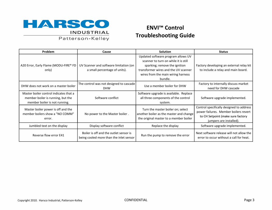
�����������
������������������
������� ����� ������ ����
+3&� ����6� ����������;� 5 2,#��? B��2 �
� ��<
,)���� ���� ������ ���������� �;� �
������������ �������� ��<'
,���������� ���������������� ��,)�
��� ������� �� �� ���������������
������ �������������� ��� �
�� �������� ������ �����,)���� ���
� �������������� �� ��� ����� ����
�� ���'
��������������� ��� ����� ������������
��� ��������������� ���� ������'
2%> ������ ��� ����� ��������������$����� ����� ��� ������� �������������
2%>,���������������������2%>
���������� �� ������������������
��������2%> ��������
� �������������� ����� ������������
����������������� � �6�������
��������������� ���� � �'��
���� ������ ����
���� ������������������������'��?�������
������������� � ���������� ����
����'
���� ����������������� ��'
� ��������������� ����������� �����
����������������� ���C(5 ��5 � � C�
�����'
(����� ��������� ������������'
$�� ����������������� ��������
� ������������������������ ����� ���
�������� �����������������������
�� ���������������������� �������������
��� �����������'��� �������������������
���% ������ �;���������������������' �������� �����������������������
���% ������ �;����������������
D����������� ������<'
E���������� ����������� 2 ����������� ������ ���� ?����������������� ���� ����������������� ��'
?����������� ������� .!A�������������� ������������ �������
��� ��������������� ����� ����� ���?� ������������������������
( ������� ������������� ���� ������� ����
��������������� �������������������'
���������3&!&'��%������� �������6�9����� #4����� �5 (��2 ($�+= 9����0

©2009 Harsco Industrial, Patterson-Kelley Printed: 12/10/2012
ENVI® Boiler Controller Getting Started Guide Installation Date: _______________________ Harsco Industrial, Patterson-Kelley 100 Burson Street East Stroudsburg, PA 18301 Telephone: (877) 728-5351 Facsimile: (570) 476-7247 www.harscopk.com
ENVI® Control GSG Rev. 0.0 6/2/2009

ENVI® Control
2
ENVI® BOILER CONTROL Harsco MACH® and MODU-FIRE® Forced Draft boilers are equipped with a combination combustion and temperature control. This control monitors the combustion and ignition of the boiler as well as maintaining temperature of the supply water. The temperature control portion modulates the boiler to maintain the desired outlet temperature based on the selected operating configuration.
The user should become thoroughly familiar with the operation of the boiler and controls before attempting to make any adjustments.
The boiler control has a text display panel. The display panel is used to setup and monitor boiler operation by means of six push buttons MENU, BACK, ENTER, UP, DOWN, and RESET as shown below. The four line screen shows boiler operating information on various screens. The display screen is backlit for ease of viewing. Pressing any key will illuminate the backlight. 1.1 INITIAL ADJUSTMENTS
The standby screen is shown upon startup. This screen shows the date, time, boiler status, supply temp and setpoint temp.
The buttons across the bottom are used to navigate through the various screens. Pushing the MENU button displays a menu of options.
The menu includes access to the STANDBY, INFORMATION, ERRORS, PROGRAM PARAMETERS, CONFIGURATION, CASCADE, and SERVICE menus. The UP and DOWN buttons are used to position the arrow next to the desired option and the ENTER button is pushed to enter that option. The list is displayed and may have more than four lines. Use the DOWN button to view the complete list.
Changing parameters requires an understanding of the parameters and the functionality of the boiler. The boiler may not function properly if parameters are changed from the fac-tory values.
MenuStandby Information Errors
MenuStandby Information Errors

ENVI® Control
3
1.1.1 Boiler Setpoint The factory default setpoint is 180 °F. If a different setpoint is desired, push the MENU button and then select PARAMETERS from the menu. A screen opens that allows the user to view and change operating parameters (see screenshot below.)
Select CH SETTINGS to adjust parameters related to the boiler’s Comfort Heat function.
For example, selecting the SETPOINT parameter opens up a screen that allows the setpoint to be changed.
The UP or DOWN buttons are used to adjust the CH setpoint up or down as desired. The ENTER button is pushed once the desired temperature is reached.
1.1.2 Other CH Parameters Other settings include the following items:
Description Value Units CH Setpoint ### °F BLR OP (Off = 0, On = 1, Off/Pump On = 2, and On/Pump On = 3) #
0-3
CH Mode # 0-8 Hysteres On (On Differential) ## °F Hysteres Off (Off Differential) ## °F Post Pump time ### Sec
Additional CH Parameters are available and used for the various CH Modes other than mode 0, the standard Setpoint & (Thermo)Stat control mode. These modes are further described in the Advanced User’s Guide.
1.1.3 Other Parameters Other parameters include DHW SETTINGS (Domestic Hot Water), BOILER SETTINGS and OEM SETTINGS. Boiler and OEM Settings are used during the initial programming of the control and are not adjustable.
ParametersCH settings DHW settings Boiler settings
ParametersCH settings DHW settings Boiler settings
CH settingsSetpoint 180°FBLR OP 1 CH mode 0
CH settingsSetpoint 180°FBLR OP 1 CH mode 0
CH settingsSetpoint 180°FBLR OP 1 CH mode 0
CH settingsSetpoint Value: 180°F Range: 45°F – 185°F
CH settingsSetpoint Value: 180°F Range: 45°F – 185°F

ENVI® Control
4
1.2 ADDITIONAL MENU ITEMS
In the main menu, STANDBY, INFORMATION, ERRORS, PROGRAM PARAMETERS, CONFIGURATION, CASCADE, and SERVICE menus are available. They are used for various functions of the boiler. These functions are described further in the Advanced User’s Guide.
These menu items will be described briefly here:
• STANDBY is the default screen and is shown during normal boiler operation.
• The INFORMATION menu lists items that the boiler monitors such as temperatures, operating conditions, and status of switches and components.
• The ERRORS menu has information about the boiler status at the time of an error.
• The PARAMETERS menu allows the user to set up selected boiler functions and operating modes.
• The CONFIGURATION menu covers basic display information such as language, units, date/time, etc.
• The CASCADE menu is used to sequence multiple boilers (up to 24 max) in a Master/Member network system. Use of this function is described in detail in the Advanced User’s Guide.
• The SERVICE menu is described below.
1.3 SERVICE MENU:
Two test modes are available in the SERVICE menu.
BNR ON TEST HI LOW
BNR OFF FAN HI LOW The first test mode allows the service technician to hold the boiler in high or low fire during firing operation so that the combustion adjustment can be performed as indicated below.
The second test mode checks the fan rate with the burner off at high speed or at low speed.
These test modes will automatically terminate after 15 minutes of inactivity or can be terminated from the control/display panel by pressing the cancel/reset button
NOTICE! Combustion adjustments should only be performed by service personnel experienced and knowledgeable on the operation of the Harsco Industrial, Patterson-Kelley boiler. See the rating plate for the minimum and maximum gas pressure of the boiler. Each boiler is furnished with a manual gas shut-off valve which has an integrated test port. The supply pressure during main burner operation must be greater than the minimum indicated on the rating plate and less than 14” W.C.
Each boiler has a specific combustion adjustment procedure that is contained in each boiler’s specific Installation & Owners Manual. The correct combustion parameters are listed in the specific manual as well. These specific procedures must be followed for the boiler being adjusted.
A typical adjustment procedure is as follows:
First set the boiler to HIGH FIRE TEST and adjust the gas supply at the main gas valve until the correct combustion parameters are achieved.
Second, set the boiler to LOW FIRE TEST and adjust the gas supply at the main gas valve until the correct combustion parameters are achieved.
ENVI® Control
5
1.4 SEQUENCE OF OPERATION 1. When the Boiler On/Off switch is turned on, power is provided through a circuit breaker to the boiler control
and the combustion blower.
2. If the high gas, low gas or low water level control is open, the boiler control locks out and displays an error.
3. When the water temperature is below the boiler control setpoint minus the hysteresis (differential), a heat request is generated.
4. Provided all limits are made, the boiler will attempt to start.
5. The controller checks that the air pressure switch is open indicating no airflow. The blower is driven towards the prestart fan speed. When the air pressure switch closes, the 25 second pre-purge time is started. After the prepurge, the blower is driven to the ignition speed.
6. A trial for ignition begins. The sequence of events is illustrated graphically below.
7. After ignition, the fan may be driven to low fire before the boiler is released to modulation.
8. The control modulates the firing rate between low and high fire to maintain the desired outlet water temperature.
9. The burner will continue firing until the outlet water temperature reaches set point plus hysteresis. At this temperature the fuel supply is shut off and the combustion air fan continues to run for a 30 second post-purge.
10. When the water temperature is reduced by the load on the system, a heat request is generated. The operating sequence will recycle to step 4.
0 1 2 3 4 5 6 7
Spark
Gas Valve
Flame Detection
Seconds
Fan
*Flame must be detected at T = 6 seconds
*
Ignition Sequence Timing
0 1 2 3 4 5 6 7
Spark
Gas Valve
Flame Detection
Seconds
Fan
*Flame must be detected at T = 6 seconds
*
Ignition Sequence Timing

Document Revision: 7
ProtoNode RER and ProtoNode LER
Startup Guide
For Interfacing Customer Product: Harsco Industrial Patterson-Kelley ENVI Control Systems and Love Controller
To Building Automation Systems: BACnet MS/TP, BACnet IP, Metasys N2, Modbus TCP, and LonWorks
APPLICABILITY & EFFECTIVITY
Explains the ProtoNode RER and LER hardware and how to install it.
The instructions are effective for the above as of March 2013

Harsco Industrial Patterson-Kelley ProtoNode Startup Guide Page 2 of 38
ProtoCessor 1991 Tarob Court Milpitas, California 95035 USA Web: www.protocessor.com Tel: (408) 964 4444 Fax: (408) 964 4425 Toll Free: (800) 317 8319 email: [email protected]
THIS PAGE INTENTIONALLY LEFT BLANK

Harsco Industrial Patterson-Kelley ProtoNode Startup Guide Page 3 of 38
ProtoCessor 1991 Tarob Court Milpitas, California 95035 USA Web: www.protocessor.com Tel: (408) 964 4444 Fax: (408) 964 4425 Toll Free: (800) 317 8319 email: [email protected]
TABLE OF CONTENTS
1 Introduction ................................................................................................................................................... 5 1.1 BTL Mark – BACnet Testing Laboratory ......................................................................................................... 5
1.2 LonMark Certification .................................................................................................................................... 5
2 BACnet/LonWorks Setup for ProtoNode RER/LER .......................................................................................... 6 2.1 Installation steps for the customer ................................................................................................................ 6
2.2 Record Identification Data ............................................................................................................................. 6
2.3 Configure the DIP Switches ............................................................................................................................ 6
2.3.1 Setting the Node/ID Device Instance (DIP Switch A0 – A7) for BACnet MS/TP, BACnet/IP, and Metasys
N2 ……………………………………………………………………………………………………………………………………………………………6
2.3.2 Setting the Serial Baud Rate (DIP Switch B0 – B3) for BACnet MS/TP and Metasys N2 ProtoNodes ....... 7
2.3.3 Using S0 – S3 bank of DIP Switches to select and load Configuration Files for ENVI and Love Controller
……………………………………………………………………………………………………………………………………………………………7
3 Interfacing the ProtoNode to ENVI and Love Controller ............................................................................... 10 3.1 ProtoNode RER and LER component layout with the cover removed ......................................................... 10
3.2 Wiring Connections to ProtoNode RER and LER for the ENVI and Love Controller ..................................... 11
3.2.1 Connecting ENVI Modbus RTU Boilers to the ProtoNode’s RS-485 ........................................................ 12
3.2.2 Biasing the Modbus RS-485 Network..................................................................................................... 12
3.2.3 End of Line Termination Switch for the Modbus RS-485 port on the ProtoNode ................................... 13
3.3 Wiring the ProtoNode RER to RS-485 Field Protocol ................................................................................... 14
3.4 Wiring the ProtoNode LER Field Port to a LonWorks network .................................................................... 15
3.5 Power-Up the ProtoNode RER or LER .......................................................................................................... 15
4 Commissioning the ProtoNode LER on a LonWorks network ........................................................................ 16 4.1 Commissioning the ProtoNode LER on a LonWorks network ...................................................................... 16
4.1.1 Instructions to Upload XIF File From the ProtoNode LER Using FS GUI Web Server .............................. 16
5 Connect the ProtoNode’s Web GUI to Setup IP Address for BACnet/IP or Modbus TCP ............................... 18 5.1 Connect the PC to the ProtoNode via the Ethernet port ............................................................................. 18
5.2 Use the ProtoNode Web GUI to Connect to the ProtoNode ....................................................................... 19
5.3 Set IP Address for BACnet/IP or Modbus TCP via GUI ................................................................................. 19
6 Chipkin Automation’s CAS BACnet Explorer for validating the Protonode in the field on a BACnet MS/TP or BACnet/IP network .............................................................................................................................................. 21
6.1 Downloading Chipkin Automation’s CAS Explorer and Requesting an Activation Key ................................ 21
6.2 CAS BACnet Setup ........................................................................................................................................ 22
6.2.1 CAS BACnet MS/TP Setup ....................................................................................................................... 22
6.2.2 CAS BACnet BACnet/IP Setup ................................................................................................................. 22
Appendix A. Troubleshooting Tips ....................................................................................................................... 23 Appendix A.1. Check Wiring and Settings ................................................................................................................ 23
Appendix A.2. Take Log With Our FieldServer Utilities............................................................................................ 23
Appendix A.3. LED Diagnostics for Modbus RTU Communications between the ProtoNode and the ENVI and the
Love Controller ........................................................................................................................................................ 26
A.3.1 ProtoNode RER and LER LEDs .................................................................................................................... 26
Appendix B. Vendor Information ......................................................................................................................... 27 Appendix B.1. ENVI and Love Controller Modbus RTU COM Settings ..................................................................... 27
Appendix B.2. ENVI Modbus RTU Mappings to BACnet MS/TP, BACnet IP, Metasys and LonWorks ..................... 27
Appendix B.3. Love Controller Modbus RTU Mappings to BACnet MS/TP, BACnet IP, Metasys N2 ....................... 28

Harsco Industrial Patterson-Kelley ProtoNode Startup Guide Page 4 of 38
ProtoCessor 1991 Tarob Court Milpitas, California 95035 USA Web: www.protocessor.com Tel: (408) 964 4444 Fax: (408) 964 4425 Toll Free: (800) 317 8319 email: [email protected]
Appendix B.4. DIP switch settings for ENVI and Love Controllers to support Metasys N2 and Modbus TCP and
BACnet for the Love Controller................................................................................................................................ 29
Appendix B.5. Address DIP Switch Settings ............................................................................................................. 31
Appendix C. Reference ......................................................................................................................................... 37 Appendix C.1. Specifications .................................................................................................................................... 37
Appendix C.1.1. Compliance with UL Regulations ............................................................................................ 37
Appendix D. Limited 2 year Warranty .................................................................................................................. 38
LIST OF FIGURES
Figure 1: A0 – A7 DIP Switches ...................................................................................................................................... 7 Figure 2: B0 – B3 DIP Switches ...................................................................................................................................... 7 Figure 3: S0 – S3 DIP Switches ....................................................................................................................................... 7 Figure 4: ProtoNode BACnet RER N34 (top) and ProtoNode LER N35 (bottom) ......................................................... 10 Figure 5: Pin outs for the ENVI’s Modbus RS-485 port and power to the ProtoNode ................................................ 11 Figure 6: Pin outs for the Love’s Modbus RS-485 port and power to the ProtoNode ................................................. 11 Figure 7: Wiring diagram for the EVNI’s Modbus RTU RS-485 to the ProtoNode’s RS-485 port. ................................ 12 Figure 8: Modbus RS-485 Biasing Switch on the ProtoNode N34 (left) and ProtoNode N35 (left). ............................ 13 Figure 9: Modbus RS-485 End-Of-Line Termination Switch on ProtoNode N34 (left) and ProtoNode N35 (right) ..... 13 Figure 10: Connection from ProtoNode to RS-485 BMS Field Protocol –BACnet MS/TP or Metasys N2 .................... 14 Figure 11: End-of-line termination on from ProtoNode to RS-485 BMS Field Protocol .............................................. 14 Figure 10: ProtoNode LER LonWorks FFT-10 2 wire screw terminal ........................................................................... 15 Figure 13: ProtoNode power pin outs ......................................................................................................................... 15 Figure 14: Sample of Fserver.XIF file being generated ................................................................................................ 17 Figure 15: Ethernet port location of ProtoNode ......................................................................................................... 18 Figure 16: FST Web GUI screen ................................................................................................................................... 19 Figure 17: FST Web GUI IP Address settings screen .................................................................................................... 20

Harsco Industrial Patterson-Kelley ProtoNode Startup Guide Page 5 of 38
ProtoCessor 1991 Tarob Court Milpitas, California 95035 USA Web: www.protocessor.com Tel: (408) 964 4444 Fax: (408) 964 4425 Toll Free: (800) 317 8319 email: [email protected]
1 INTRODUCTION
ProtoNode is an external, high performance Building Automation multi-protocol gateway that has been
preprogrammed for Harsco’s ENVI boiler control system and the Love Boiler controller to support BACnet®1MS/TP,
BACnet/IP, Metasys®2 N2 by JCI, Modbus TCP, and LonWorks®
3. Configurations for the various protocols are
stored within the ProtoNode and are selectable via DIP switches for fast and easy installation. It is not necessary to
download any configuration files to support the required applications.
This document provides the necessary information to facilitate installation of the ProtoNode.
1.1 BTL Mark – BACnet Testing Laboratory
1.2 LonMark Certification
1 BACnet is a registered trademark of ASHRAE 2 Metasys is a registered trademark of Johnson Controls Inc. 3 4 LonWorks is a registered trademark of Echelon Corporation
The BTL Mark on the ProtoNode RER is a symbol that indicates to everyone that a
product has passed a series of rigorous tests conducted by an independent laboratory
which verifies that the product correctly implements the BACnet features claimed in
the listing. The mark is a symbol of a high-quality BACnet product. Go to
http://www.bacnetinternational.net/btl/ for more information about the BACnet
Testing Laboratory.
LonMark International is the recognized authority for certification, education, and
promotion of interoperability standards for the benefit of manufacturers, integrators
and end users. LonMark International has developed extensive product certification
standards and tests to provide the integrator and user with confidence that products
from multiple manufacturers utilizing LonMark devices work together. FieldServer
Technologies has more LonMark Certified gateways than any other gateway
manufacturer, including the ProtoCessor, ProtoCarrier and ProtoNode for OEM
applications and the full featured, configurable gateways.

Harsco Industrial Patterson-Kelley ProtoNode Startup Guide Page 6 of 38
ProtoCessor 1991 Tarob Court Milpitas, California 95035 USA Web: www.protocessor.com Tel: (408) 964 4444 Fax: (408) 964 4425 Toll Free: (800) 317 8319 email: [email protected]
2 BACNET/LONWORKS SETUP FOR PROTONODE RER/LER
2.1 Installation steps for the customer
1. Record the information about the unit. See Section 2.2
2. Configure each ENVI controller’s Modbus node address for each ENVI connected to the ProtoNode. The
first node must start at 1 and go up to 16; if you have a total of 16 ENVI’s connected to the ProtoNode.
See Appendix B.1
3. For Love Controller connected to the ProtoNode, the Modbus Node address must be set to 1. See
Appendix B.1
4. Set A, B, and S DIP Switch banks on ProtoNode for field protocol baud rate, Node-ID/Device Instance, and
proper configuration. See Section 2.3
5. Connect the ProtoNode to the Field protocol port (3 pin Phoenix connector) and the ENVI’s or Love
Controller’s RS-485 port to the ProtoNode’s RS-485 interface (located on the ProtoNode’s 6 pin
connector). See Section 3
6. Power up the ProtoNode RER and LER. See Section 3.6
7. Commission the ProtoNode on the LonWorks Network. This needs to be done by the LonWorks
administrator use a LonWorks Commissioning tool. See Section 4
8. If the Field protocol is BACnet/IP or Modbus TCP, refer to Section 4 to run the ProtoNode Web GUI to
change IP address. See Section 5
2.2 Record Identification Data
Each ProtoNode has a unique part number located on the underside of the unit. The numbers are as
follows:
Part number FPC-N34-103-126-0710:
o Supports 1 through 16 ENVI boilers to BACnet/IP, BACnet MS/TP, Modbus TCP, and
Metasys N2.
o Supports 1 Love controller to BACnet/IP, BACnet MS/TP, Modbus TCP, and Metasys N2.
Part number FPC-N35-103-401-0771:
o Supports 1 through 13 ENVI boilers to LonWorks.
o Supports 1 Love controller to LonWorks.
These part numbers should be recorded, as they may be required for technical support.
2.3 Configure the DIP Switches
2.3.1 Setting the Node/ID Device Instance (DIP Switch A0 – A7) for BACnet MS/TP,
BACnet/IP, and Metasys N2
The A Bank DIP switches on the ProtoNode RER allow users to set the Node-ID/Device Instance on the
Field RS-485.

Harsco Industrial Patterson-Kelley ProtoNode Startup Guide Page 7 of 38
ProtoCessor 1991 Tarob Court Milpitas, California 95035 USA Web: www.protocessor.com Tel: (408) 964 4444 Fax: (408) 964 4425 Toll Free: (800) 317 8319 email: [email protected]
DIP switches A0 – A7 can also be used to set the MAC Address for BACnet MS/TP and BACnet/IP
Figure 1: A0 – A7 DIP Switches
Please refer to Appendix B.3 for the full range of addresses to set Node-ID/Device Instance.
NOTE: When setting DIP Switches, please ensure that power to the board is OFF.
2.3.2 Setting the Serial Baud Rate (DIP Sw itch B0 – B3) for BACnet MS/TP and Metasys
N2 ProtoNodes
DIP Switches B0 – B3 can be used to set the serial baud rate to match the baud rate provided by the
Building Management System for BACnet MS/TP.
Metasys N2 is always defaulted to 9600 baud and the B bank is disabled.
B0 B1 B2 B3
Figure 2: B0 – B3 DIP Switches
2.3.2.1 Baud Rate DIP Switch Selection
Baud B0 B1 B2 B3
9600 On On On Off
19200 Off Off Off On
38400 On On Off On
57600 Off Off On On
76800 On Off On On
2.3.3 Using S0 – S3 bank of DIP Switches to select and load Configuration Files for ENVI
and Love Controller
The S bank of DIP switches, S0 - S3 is used to select and load a configuration file from a group of
pretested/preloaded configuration files which are stored in the ProtoNode RER FPC-N34-103-126-0710
(BACnet MS/TP, BACnet/IP, Modbus TCP, Metasys N2) and the ProtoNode LER FPC-N35-103-401-0771
(LonWorks).
S0 S1 S2 S3
Figure 3: S0 – S3 DIP Switches

Harsco Industrial Patterson-Kelley ProtoNode Startup Guide Page 8 of 38
ProtoCessor 1991 Tarob Court Milpitas, California 95035 USA Web: www.protocessor.com Tel: (408) 964 4444 Fax: (408) 964 4425 Toll Free: (800) 317 8319 email: [email protected]
2.3.3.1 S0 – S3 DIP Switch Configuration Settings
A. BACnet MS/TP and BACnet IP for ENVI boilers
The following chart describes S0 - S3 DIP Switch configuration settings for the ENVI’s 1 through 16 boilers
applications to support BACnet MS/TP and BACnet/IP on a ProtoNode RER (Part # FPC-N34-103-126-
0710).
ProtoNode RER FPC-N34-103-126-0710 ProtoNode S Bank DIP Switches
Profile S0 S1 S2 S3
BACnet IP/BACnet MS/TP 1 ENVI Off Off Off Off
BACnet IP/BACnet MS/TP 2 ENVI On Off Off Off
BACnet IP/BACnet MS/TP 3 ENVI Off On Off Off
BACnet IP/BACnet MS/TP 4 ENVI On On Off Off
BACnet IP/BACnet MS/TP 5 ENVI Off Off On Off
BACnet IP/BACnet MS/TP 6 ENVI On Off On Off
BACnet IP/BACnet MS/TP 7 ENVI Off On On Off
BACnet IP/BACnet MS/TP 8 ENVI On On On Off
BACnet IP/BACnet MS/TP 9 ENVI Off Off Off On
BACnet IP/BACnet MS/TP 10 ENVI On Off Off On
BACnet IP/BACnet MS/TP 11 ENVI Off On Off On
BACnet IP/BACnet MS/TP 12 ENVI On On Off On
BACnet IP/BACnet MS/TP 13 ENVI Off Off On On
BACnet IP/BACnet MS/TP 14 ENVI On Off On On
BACnet IP/BACnet MS/TP 15 ENVI Off On On On
BACnet IP/BACnet MS/TP 16 ENVI On On On On
Support for 1 through 16 ENVI’s to Metasys N2 or Modbus TCP see Appendix B.2
Support for 1 Love Controller to support BACnet MS/TP, BACnet/IP, Metasys N2 or Modbus TCP
see Appendix B.2
S Bank DIP Switches
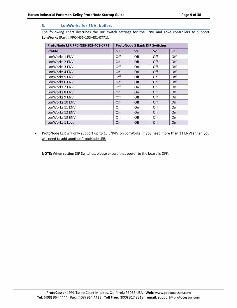
Harsco Industrial Patterson-Kelley ProtoNode Startup Guide Page 9 of 38
ProtoCessor 1991 Tarob Court Milpitas, California 95035 USA Web: www.protocessor.com Tel: (408) 964 4444 Fax: (408) 964 4425 Toll Free: (800) 317 8319 email: [email protected]
B. LonWorks for ENVI boilers
The following chart describes the DIP switch settings for the ENVI and Love controllers to support
LonWorks (Part # FPC-N35-103-401-0771).
ProtoNode LER FPC-N35-103-401-0771 ProtoNode S Bank DIP Switches
Profile S0 S1 S2 S3
LonWorks 1 ENVI Off Off Off Off
LonWorks 2 ENVI On Off Off Off
LonWorks 3 ENVI Off On Off Off
LonWorks 4 ENVI On On Off Off
LonWorks 5 ENVI Off Off On Off
LonWorks 6 ENVI On Off On Off
LonWorks 7 ENVI Off On On Off
LonWorks 8 ENVI On On On Off
LonWorks 9 ENVI Off Off Off On
LonWorks 10 ENVI On Off Off On
LonWorks 11 ENVI Off On Off On
LonWorks 12 ENVI On On Off On
LonWorks 13 ENVI Off Off On On
LonWorks 1 Love On Off On On
ProtoNode LER will only support up to 13 ENVI’s on LonWorks. If you need more than 13 ENVI’s then you
will need to add another ProtoNode LER.
NOTE: When setting DIP Switches, please ensure that power to the board is OFF.

Harsco Industrial Patterson-Kelley ProtoNode Startup Guide Page 10 of 38
ProtoCessor 1991 Tarob Court Milpitas, California 95035 USA Web: www.protocessor.com Tel: (408) 964 4444 Fax: (408) 964 4425 Toll Free: (800) 317 8319 email: [email protected]
3 INTERFACING THE PROTONODE TO ENVI AND LOVE CONTROLLER
3.1 ProtoNode RER and LER component layout with the cover removed
Figure 4: ProtoNode BACnet RER N34 (top) and ProtoNode LER N35 (bottom)

Harsco Industrial Patterson-Kelley ProtoNode Startup Guide Page 11 of 38
ProtoCessor 1991 Tarob Court Milpitas, California 95035 USA Web: www.protocessor.com Tel: (408) 964 4444 Fax: (408) 964 4425 Toll Free: (800) 317 8319 email: [email protected]
3.2 Wiring Connections to ProtoNode RER and LER for the ENVI and Love Controller
ProtoNode 6 Pin Phoenix connector – Pin outs to ENVI’s and Love’s Modbus RTU and Power
Figure 5: Pin outs for the ENVI’s Modbus RS-485 port and power to the ProtoNode
Figure 6: Pin outs for the Love’s Modbus RS-485 port and power to the ProtoNode

Harsco Industrial Patterson-Kelley ProtoNode Startup Guide Page 12 of 38
ProtoCessor 1991 Tarob Court Milpitas, California 95035 USA Web: www.protocessor.com Tel: (408) 964 4444 Fax: (408) 964 4425 Toll Free: (800) 317 8319 email: [email protected]
3.2.1 Connecting ENVI Modbus RTU Boilers to the ProtoNode’s RS -485
Connect ENVI’s Modbus COM 1A (RS485+) to ProtoNode’s pin 1 labeled B+ (RS485+) on the Phoenix 6 pin
connector.
Connect ENVI’s Modbus COM 1B (RS485-) to ProtoNode’s pin 2 labeled A- (RS485-) on the Phoenix 6 pin
connector.
Do not connect Ground between ENVI and the ProtoNode’s RS485 Ground.
Figure 7: Wiring diagram for the EVNI’s Modbus RTU RS-485 to the ProtoNode’s RS-485 port.
3.2.2 Biasing the Modbus RS-485 Network
An RS-485 network with more than one device needs to have biasing to ensure proper communication.
The biasing needs to be done on one device.
None of the ENVI’s support biasing.
The ProtoNode has a 510 Ohm resistor switch that is used to set the biasing. The ProtoNode’s default
position for the Biasing switch is ON from the factory.
The biasing MUST always be left in the ON position. The ON position is when the 2 RED biasing jumpers
straddle the 4 pins closest to the inside of the board of the ProtoNode. See Figure 8 below

Harsco Industrial Patterson-Kelley ProtoNode Startup Guide Page 13 of 38
ProtoCessor 1991 Tarob Court Milpitas, California 95035 USA Web: www.protocessor.com Tel: (408) 964 4444 Fax: (408) 964 4425 Toll Free: (800) 317 8319 email: [email protected]
Figure 8: Modbus RS-485 Biasing Switch on the ProtoNode N34 (left) and ProtoNode N35 (left).
3.2.3 End of Line Termination Switch for the Modbus RS-485 port on the ProtoNode
On long RS-485 cabling runs, the RS-485 trunk must be properly terminated at each end.
If the ProtoNode is placed at one of the ends of the trunk, you turn the Blue RS-485 End-of- Line
Terminating switch to ON position.
On short cabling runs which most of the ENVI applications are, the EOL switch does not to need to be
turned ON. The default setting for this Blue EOL switch is OFF.
All ways leave the single Red Jumper in the A position.
Figure 9: Modbus RS-485 End-Of-Line Termination Switch on the ProtoNode N34 (left) and ProtoNode N35 (right)
RS-485 Bias Switch RS-485 Bias Switch
Modbus RS-485 EOL Switch Switch
Modbus RS-485 EOL Switch EOLEOL Switch
Leave in A Position

Harsco Industrial Patterson-Kelley ProtoNode Startup Guide Page 14 of 38
ProtoCessor 1991 Tarob Court Milpitas, California 95035 USA Web: www.protocessor.com Tel: (408) 964 4444 Fax: (408) 964 4425 Toll Free: (800) 317 8319 email: [email protected]
3.3 Wiring the ProtoNode RER to RS-485 Field Protocol
Connection from ProtoNode RER to BACnet MS/TP and Metasys N2 networks
Connect BACnet MS/TP or N2 RS485 to the 3-pin RS485 connector on ProtoNode RER as shown below.
Figure 10: Connection from ProtoNode to RS-485 BMS Field Protocol –BACnet MS/TP or Metasys N2
See Section 4 for information on connecting the ProtoNode RER to BACnet/IP or Modbus TCP network.
If the ProtoNode is the last device on the BACnet MS/TP or Metasys N2 RS-485 trunk, then enable the
End-of-line termination needs to be enabled. The default is off.
Figure 11: End-of-line termination on from ProtoNode to RS-485 BMS Field Protocol
End-of-Line Switch

Harsco Industrial Patterson-Kelley ProtoNode Startup Guide Page 15 of 38
ProtoCessor 1991 Tarob Court Milpitas, California 95035 USA Web: www.protocessor.com Tel: (408) 964 4444 Fax: (408) 964 4425 Toll Free: (800) 317 8319 email: [email protected]
3.4 Wiring the ProtoNode LER Field Port to a LonWorks network
Connect the ProtoNode to the field network with the LonWorks terminal using a twisted pair non-
shielded cable. LonWorks has no polarity.
Figure 12: ProtoNode LER LonWorks FFT-10 2 wire screw terminal
3.5 Power-Up the ProtoNode RER or LER
Apply power to the device. Ensure that the power supply used complies with the specifications provided in
Appendix C.1. Ensure that the cable is grounded using the “Frame-GND” terminal. The ProtoNode is factory set to
accept both 9-30VDC and 12-24 VAC.
Voltage Pin outs
Figure 13: ProtoNode power pin outs

Harsco Industrial Patterson-Kelley ProtoNode Startup Guide Page 16 of 38
ProtoCessor 1991 Tarob Court Milpitas, California 95035 USA Web: www.protocessor.com Tel: (408) 964 4444 Fax: (408) 964 4425 Toll Free: (800) 317 8319 email: [email protected]
4 COMMISSIONING THE PROTONODE LER ON A LONWORKS NETWORK
Commissioning may only be performed by the LonWorks administrator.
4.1 Commissioning the ProtoNode LER on a LonWorks network
To commission the ProtoNode LER LonWorks port, insert a small screwdriver in the commissioning hole on the
face of the LER’s enclosure to access the Service Pin. See the illustration on the ProtoNode LER as to which way to
toggle the screw driver during commissioning.
If an XIF file is required, see steps Section 4.4.1 to generate XIF
4.1.1 Instructions to Upload XIF File From the ProtoNode LER Using FS GUI Web Server
Connect a standard cat5 Ethernet cable between the PC and ProtoNode
The Default IP Address of the ProtoNode is 192.168.1.24, Subnet Mask is 255.255.255.0. If the PC and the
ProtoNode are on different IP Networks, assign a static IP Address to the PC on the 192.168.1.xxx network
For Windows XP:
Go to > >
Right-click on Local Area Connection > Properties
Highlight >
For Windows 7:
Go to > >
> >
Right-click on Local Area Connection > Properties
Highlight >
LonWorks Service Pin

Harsco Industrial Patterson-Kelley ProtoNode Startup Guide Page 17 of 38
ProtoCessor 1991 Tarob Court Milpitas, California 95035 USA Web: www.protocessor.com Tel: (408) 964 4444 Fax: (408) 964 4425 Toll Free: (800) 317 8319 email: [email protected]
For Windows XP and Windows 7, select: Use the following IP address
Click twice
Open a web browser and go to the following address: IP address of ProtoCessor/fserver.xif
Example: 192.168.1.24/fserver.xif
Download and save the file onto the PC.
Figure 14: Sample of Fserver.XIF file being generated

Harsco Industrial Patterson-Kelley ProtoNode Startup Guide Page 18 of 38
ProtoCessor 1991 Tarob Court Milpitas, California 95035 USA Web: www.protocessor.com Tel: (408) 964 4444 Fax: (408) 964 4425 Toll Free: (800) 317 8319 email: [email protected]
5 CONNECT THE PROTONODE’S WEB GUI TO SETUP IP ADDRESS FOR BACNET/IP OR
MODBUS TCP
5.1 Connect the PC to the ProtoNode via the Ethernet port
Figure 15: Ethernet port location of ProtoNode
Connect a standard CAT5 Ethernet cable (straight through or cross) between the PC and ProtoNode
The Default IP Address of the ProtoNode is 192.168.1.24, Subnet Mask is 255.255.255.0. If the PC and the
ProtoNode are on different IP Networks, assign a static IP Address to the PC on the 192.168.1.xxx network
Go to > >
Right-click on Local Area Connection > Properties
Highlight >
Select: Use the following IP address
Click twice
Ethernet Port

Harsco Industrial Patterson-Kelley ProtoNode Startup Guide Page 19 of 38
ProtoCessor 1991 Tarob Court Milpitas, California 95035 USA Web: www.protocessor.com Tel: (408) 964 4444 Fax: (408) 964 4425 Toll Free: (800) 317 8319 email: [email protected]
5.2 Use the ProtoNode Web GUI to Connect to the ProtoNode
Open PC web browser; enter the default IP address of the ProtoNode 192.168.1.24, to determine if the
ProtoNode is up and communicating.
Figure 16: FST Web GUI screen
5.3 Set IP Address for BACnet/IP or Modbus TCP via GUI
Open a PC web browser, enter the default IP address of the ProtoNode 192.168.1.24 and connect to the
ProtoNode.
From the GUI main home page, click on setup and then Network Settings to enter the Edit IP Address
Settings menu.
Modify the IP address (N1 IP address field) of the ProtoNode Ethernet port.
If necessary, change the Netmask (N1 Netmask field).
Type in a new Subnet Mask.
If necessary, change the IP Gateway (Default Gateway field).
Type in a new IP Gateway.
Note: If the ProtoNode is connected to a router, the IP Gateway of the ProtoNode should be set to the IP
address of the router that it is connected to.
Reset ProtoNode.
Unplug Ethernet cable from PC and connect it to the network hub or router.

Harsco Industrial Patterson-Kelley ProtoNode Startup Guide Page 20 of 38
ProtoCessor 1991 Tarob Court Milpitas, California 95035 USA Web: www.protocessor.com Tel: (408) 964 4444 Fax: (408) 964 4425 Toll Free: (800) 317 8319 email: [email protected]
Figure 17: FST Web GUI IP Address settings screen

Harsco Industrial Patterson-Kelley ProtoNode Startup Guide Page 21 of 38
ProtoCessor 1991 Tarob Court Milpitas, California 95035 USA Web: www.protocessor.com Tel: (408) 964 4444 Fax: (408) 964 4425 Toll Free: (800) 317 8319 email: [email protected]
6 CHIPKIN AUTOMATION’S CAS BACNET EXPLORER FOR VALIDATING THE PROTONODE
IN THE FIELD ON A BACNET MS/TP OR BACNET/IP NETWORK
Chipkin Automation has extended to Harsco and their customers a free complementary 2 week fully functional
copy of CAS BACnet Explorer that can be used to validate BACnet MS/TP and/or BACnet/IP communications of the
ProtoNode in the field without having to have the BMS Integrator on site. A Serial or USB to RS-485 converter is
needed to test BACnet MS/TP.
6.1 Downloading Chipkin Automation’s CAS Explorer and Requ esting an Activation Key
To request a 2 week complementary BACnet CAS key, go to http://app.chipkin.com/activation/twoweek/
and fill in all the information. Enter Vendor Code “harsco12”. Once completed, the key will be sent to the
email address that was submitted. From this email from Chipkin Automation, the long key will need to be
copied and pasted into the CAS key activation page.
Go to Chipkin Automation’s web site, download, and install the CAS BACnet Explorer to your PC
http://www.chipkin.com/technical-resources/cas-bacnet-explorer/.
In the CAS Activation form, enter the email address and paste the CAS key that was sent from Chipkin
Automation. Once completed, select Activation.

Harsco Industrial Patterson-Kelley ProtoNode Startup Guide Page 22 of 38
ProtoCessor 1991 Tarob Court Milpitas, California 95035 USA Web: www.protocessor.com Tel: (408) 964 4444 Fax: (408) 964 4425 Toll Free: (800) 317 8319 email: [email protected]
6.2 CAS BACnet Setup
These are the instructions to set CAS Explorer up for the first time on BACnet MS/ST and BACnet/IP.
6.2.1 CAS BACnet MS/TP Setup
Using the Serial or USB to RS-485 converter, connect it to your PC and the 3 Pin BACnet MS/TP connector
on the ProtoNode RER.
In CAS Explorer, do the following:
o Click on settings o Check the BACnet MSTP box and uncheck the BACnet IP and BACnet Ethernet boxes. o Set the BACnet MSTP MAC address to 0. o Set the BACnet MSTP Baud Rate to 38400. o Click Ok. o On the bottom right-hand corner, make sure that the BACnet MSTP box is green. o Click on discover. o Check all 4 boxes. o Click Send.
6.2.2 CAS BACnet BACnet/IP Setup
See Section 4.1 to set the IP address and subnet of the PC that will be running the CAS Explorer.
Connect a straight through or cross Ethernet cable from the PC to the ProtoNode.
In CAS Explorer, do the following:
o Click on settings o Check the BACnet IP box and uncheck the BACnet MSTP and BACnet Ethernet boxes. o In the “Select a Network Device” box, select the network card of the PC by clicking on it. o Click Ok. o On the bottom right-hand corner, make sure that the BACnet IP box is green. o Click on discover. o Check all 4 boxes. o Click Send.

Harsco Industrial Patterson-Kelley ProtoNode Startup Guide Page 23 of 38
ProtoCessor 1991 Tarob Court Milpitas, California 95035 USA Web: www.protocessor.com Tel: (408) 964 4444 Fax: (408) 964 4425 Toll Free: (800) 317 8319 email: [email protected]
Appendix A. Troubleshooting Tips
Appendix A.1. Check Wiring and Settings
No COMS on Modbus RTU side. If TX/RX is not flashing rapidly then there is a COM issue on the Modbus side and you need to check the following things: o Visual observations of LEDs on ProtoNode. See Appendix A.3 o Check baud rate, parity, data bits, stop bits o Check Modbus device address o Verify wiring
Field COM problems. o Visual observations of LEDs on ProtoNode. See Appendix A.3 o Visual dipswitch settings (using correct baud rate and device instance) o Verify IP address setting o Verify wiring
If the problem still exists, a log needs to be taken and sent to FieldServer. See Appendix A.2
Appendix A.2. Take Log With Our FieldServer Utilities
Once the log is complete, email it to [email protected]. The log will allow us to rapidly diagnose
the problem.
Make sure the FieldServer utilities are loaded on the PC.
http://fieldserver.com/techsupport/utility/utility.php
Disable any wireless Ethernet adapters on the PC/Laptop.
Disable firewall and virus protection software.
Connect a standard cat5 Ethernet cable between the PC and ProtoNode.
The Default IP Address of the ProtoNode is 192.168.1.24, Subnet Mask is 255.255.255.0. If the PC and the
ProtoNode are on different IP Networks, assign a static IP Address to the PC on the 192.168.1.xxx network
For Windows XP:
Go to > >
Right-click on Local Area Connection > Properties
Highlight >
Ethernet Port

Harsco Industrial Patterson-Kelley ProtoNode Startup Guide Page 24 of 38
ProtoCessor 1991 Tarob Court Milpitas, California 95035 USA Web: www.protocessor.com Tel: (408) 964 4444 Fax: (408) 964 4425 Toll Free: (800) 317 8319 email: [email protected]
For Windows 7:
Go to > >
> >
Right-click on Local Area Connection > Properties
Highlight >
For Windows XP and Windows 7, select: Use the following IP address
Click twice
Double click on the FST Diag Utility.
Step 1: Select a Field Server IP Address.
The IP address can be entered manually or selected by clicking on button 1 using the Utility.
Type in the ProtoNode IP address Default IP Address is 192.168.1.24
Press here to retrieve the IP address.
Locate where the log is saved on the PC

Harsco Industrial Patterson-Kelley ProtoNode Startup Guide Page 25 of 38
ProtoCessor 1991 Tarob Court Milpitas, California 95035 USA Web: www.protocessor.com Tel: (408) 964 4444 Fax: (408) 964 4425 Toll Free: (800) 317 8319 email: [email protected]
Step 2: Take a Log
Press the Take Log button. While the Utility runs a few DOS prompts will flash across the monitor. Don't
click or type anything in to these DOS prompts. This step may take a few minutes depending on the
chosen Log Type and computer speed. When the Utility is finished you will be presented with a log of
events that have occurred.
Step 3: Send Log
Click the “Send Log” button located near the bottom of the dialog. The following dialog should appear.
Push the ‘Locate Folder’ button to launch explorer and have it point directly at the correct folder. The file
upload.zip must be sent to [email protected].
Step 4: Close the Program
Press the exit button when the log is completed
Select a log type.
Press the Take Log button.

Harsco Industrial Patterson-Kelley ProtoNode Startup Guide Page 26 of 38
ProtoCessor 1991 Tarob Court Milpitas, California 95035 USA Web: www.protocessor.com Tel: (408) 964 4444 Fax: (408) 964 4425 Toll Free: (800) 317 8319 email: [email protected]
Appendix A.3. LED Diagnostics for Modbus RTU Communications between the ProtoNode and the ENVI
and the Love Controller
Please see the diagram below for LED Locations
A.3.1 ProtoNode RER and LER LEDs
Light Description For ProtoNode RER and LER
RTC Unused
RUN The RUN LED will start flashing 20 seconds after power indicating normal operation.
ERR
The SYS ERR LED will go on solid 15 seconds after power up. It will turn off after 5 seconds. A steady red light will indicate there is a system error on the ProtoNode LER. If this occurs, immediately report the related “system error” shown in the error screen of the RUI interface to FieldServer Technologies for evaluation.
RX The RX LED will flash when a message is received on the ProtoNode port.
TX The TX LED will flash when a message is sent on the ProtoNode port.
PWR This is the power light and should show steady green at all times when the ProtoNode is powered.

Harsco Industrial Patterson-Kelley ProtoNode Startup Guide Page 27 of 38
ProtoCessor 1991 Tarob Court Milpitas, California 95035 USA Web: www.protocessor.com Tel: (408) 964 4444 Fax: (408) 964 4425 Toll Free: (800) 317 8319 email: [email protected]
Appendix B. Vendor Information
Appendix B.1. ENVI and Love Controller Modbus RTU COM Settings
Settings ENVI Boiler 1 ENVI Boiler 2 ENVI Boiler 3 Love Controller
Baud Rate 9600 9600 9600 9600
Data Bits None None None None
Stop Bits 8 8 8 8
Parity 1 1 1 1
Modbus Node ID 1 2 3 1
Appendix B.2. ENVI Modbus RTU Mappings to BACnet MS/TP, BACnet IP, Metasys and LonWorks
Map_Descriptor_Name BACnet
Object Type BACnet
Object Id N2 Data
Type N2 Point Address
Lonworks Name Lonworks SNVT
Type
State AI 1 AI 1 nvoXXState SNVT_count_inc_f
Supply Temp AI 2 AI 2 nvoXXSupplyTmp SNVT_count_inc_f
Return Temp AI 3 AI 3 nvoXXReturnTmp SNVT_count_inc_f
DHW Temp AI 4 AI 4 nvoXXDHWTmp SNVT_count_inc_f
Header Temp AI 5 AI 5 nvoXXHeaderTmp SNVT_count_inc_f
Firing Rate AI 6 AI 6 nvoXXFiringRate SNVT_lev_percent
Flue Gas Temp AI 7 AI 7 nvoXXFlueGasTmp SNVT_count_inc_f
HX Temp AI 8 AI 8 nvoXXHXTmp SNVT_count_inc_f
Outside Temp AI 9 AI 9 nvoXXOutsideTmp SNVT_count_inc_f
Flame Signal AI 10 AI 10 nvoXXFlameSignal SNVT_count_inc_f
CH Setpoint AV 11 AO 11 nvi/nvoXXCHSP SNVT_count_inc_f
DHW Setpoint AV 12 AO 12 nvi/nvoXXDHWSP SNVT_count_inc_f
Boiler Operation AV 13 AO 13 nvi/nvoXXBlrOperatn SNVT_count_inc_f
High Outdoor Air Temp AV 14 AO 14 nvi/nvoXXHiOATmp SNVT_count_inc_f
Min Outdoor Air Setpoint AV 15 AO 15 nvi/nvoXXMinOASP SNVT_count_inc_f
Low Outdoor Air Temp AV 16 AO 16 nvi/nvoXXLoOATmp SNVT_count_inc_f
Max Outdoor Air Setpoint AV 17 AO 17 nvi/nvoXXMaxOASP SNVT_count_inc_f
Outdoor Air Shutdown Temp AV 18 AO 18 nvi/nvoXXOAShtdwnTmp SNVT_count_inc_f
Night Setback AV 19 AO 19 nvi/nvoXXNightStback SNVT_count_inc_f
Error Code AI 20 AI 20 nvoXXErrorCode SNVT_count_inc_f
Analog In AI 21 AI 21 nvoXXAnalogIn SNVT_volt
Analog Out AI 22 AI 22 nvoXXAnalogOut SNVT_volt
Ignitions AI 23 AI 23 nvoXXIgnitions SNVT_count_inc_f
Burner High Hours AI 24 AI 24 nvoXXBrnrHiHrs SNVT_time_hour
Burner Medium Hours AI 25 AI 25 nvoXXBrnrMedHrs SNVT_time_hour
Burner Low Hours AI 26 AI 26 nvoXXBrnrLoHrs SNVT_time_hour
Water Level BI 27 DI 27 nvoXXWaterLvl SNVT_switch
Low Gas Pressure BI 28 DI 28 nvoXXLoGasPrs SNVT_switch
Air Pressure BI 29 DI 29 nvoXXAirPrs SNVT_switch
Blocked Flue BI 30 DI 30 nvoXXBlckdFlue SNVT_switch

Harsco Industrial Patterson-Kelley ProtoNode Startup Guide Page 28 of 38
ProtoCessor 1991 Tarob Court Milpitas, California 95035 USA Web: www.protocessor.com Tel: (408) 964 4444 Fax: (408) 964 4425 Toll Free: (800) 317 8319 email: [email protected]
CH Pump BI 31 DI 31 nvoXXCHPump SNVT_switch
DHW Pump BI 32 DI 32 nvoXXDHWPump SNVT_switch
Air Damper BI 33 DI 33 nvoXXAirDamper SNVT_switch
High Gas Pressure BI 34 DI 34 nvoXXHiGasPrs SNVT_switch
ET Error Number AI 35 AI 35 nvoXXETErrorNum SNVT_count_inc_f
ET Supply Temp AI 36 AI 36 nvoXXETSupTmp SNVT_count_inc_f
ET Return Temp AI 37 AI 37 nvoXXETRetTmp SNVT_count_inc_f
ET DHW Temp AI 38 AI 38 nvoXXETDHWTmp SNVT_count_inc_f
ET Flue Gas Temp AI 39 AI 39 nvoXXETFluGasTmp SNVT_count_inc_f
ET HX Temp AI 40 AI 40 nvoXXETHXTmp SNVT_count_inc_f
ET Outside Temp AI 41 AI 41 nvoXXETOtsdTmp SNVT_count_inc_f
Boiler State AI 42 AI 42 nvoXXBlrState SNVT_count_inc_f
Frost Protection BI 43 DI 43 nvoXXFrstPrtctn SNVT_switch
DHW Mode BI 44 DI 44 nvoXXDHWMode SNVT_switch
CH Mode BI 45 DI 45 nvoXXCHMode SNVT_switch
ET Month AI 46 AI 46 nvoXXETMonth SNVT_count_inc_f
ET Day AI 47 AI 47 nvoXXETDay SNVT_count_inc_f
ET Year AI 48 AI 48 nvoXXETYear SNVT_count_inc_f
ET Hours AI 49 AI 49 nvoXXETHrs SNVT_count_inc_f
ET Minutes AI 50 AI 50 nvoXXETMinutes SNVT_count_inc_f
ET Day Count High AI 51 AI 51 nvoXXETDayCntHi SNVT_count_inc_f
ET Day Count Low AI 52 AI 52 nvoXXETDayCntLo SNVT_count_inc_f
ET Run Hours AI 53 AI 53 nvoXXETRunHrs SNVT_time_hour
Appendix B.3. Love Controller Modbus RTU Mappings to BACnet MS/TP, BACnet IP, Metasys N2
Map_Descriptor_Name BACnet Object Type BACnet Object
Id N2 Data Type
N2 Point Address
Setpoint AI 1 AI 1
PB Proportional Band AI 2 AI 2
Ti Integral time AI 3 AI 3
Td Derivative time AI 4 AI 4
Hyst Value 1st output grp AI 5 AI 5
Alm 1 Type AI 6 AI 6
Alm 2 Type AI 7 AI 7
Alm 3 Type AI 8 AI 8
Alm 1 Upper Limit AI 9 AI 9
Alm 1 Lower Limit AI 10 AI 10
Alm 2 Upper Limit AV 11 AI 11
Alm 2 Lower Limit AV 12 AI 12
Alm 3 Upper Limit AV 13 AI 13
Alm 3 Lower Limit AV 14 AI 14

Harsco Industrial Patterson-Kelley ProtoNode Startup Guide Page 29 of 38
ProtoCessor 1991 Tarob Court Milpitas, California 95035 USA Web: www.protocessor.com Tel: (408) 964 4444 Fax: (408) 964 4425 Toll Free: (800) 317 8319 email: [email protected]
Appendix B.4. DIP switch settings for ENVI and Love Controllers to support Metasys N2 and Modbus TCP
and BACnet for the Love Controller
Note: The lid on top of the ProtoNode has to be removed in order to select the A Bank of DIP switches. Pull on
the lid while holding the on to the 6 pin Phoenix connector. Please do not hold the wall mount tabs as these
are designed to break off if not required!
To set select these configurations, open the ProtoNode and select the A bank of switches (A1 or A2) on
the small ProtoCessor module that sits on top of the ProtoCarrier (inside the ProtoNode).
ProtoCessor A1 DIP switch starts on the bottom of the A bank of DIP switches below.
ProtoCessor A3-A8 DIP switches are disabled.
ProtoNode RER ProtoCarrier DIP Switches ProtoCessor DIP Switches (Remove Cover)
Profile - FPC-N34-103-126-0710 S0 S1 S2 S3 A1 A2 A3 A4 A5 A6 A7 A8
Metasys N2 1 ENVI Off Off Off Off On Off Off Off Off Off Off Off
Metasys N2 2 ENVI On Off Off Off On Off Off Off Off Off Off Off
Metasys N2 3 ENVI Off On Off Off On Off Off Off Off Off Off Off
Metasys N2 4 ENVI On On Off Off On Off Off Off Off Off Off Off
Metasys N2 5 ENVI Off Off On Off On Off Off Off Off Off Off Off
Metasys N2 6 ENVI On Off On Off On Off Off Off Off Off Off Off
Metasys N2 7 ENVI Off On On Off On Off Off Off Off Off Off Off
Metasys N2 8 ENVI On On On Off On Off Off Off Off Off Off Off
Metasys N2 9 ENVI Off Off Off On On Off Off Off Off Off Off Off
Metasys N2 10 ENVI On Off Off On On Off Off Off Off Off Off Off
Metasys N2 11 ENVI Off On Off On On Off Off Off Off Off Off Off
Metasys N2 12 ENVI On On Off On On Off Off Off Off Off Off Off
Metasys N2 13 ENVI Off Off On On On Off Off Off Off Off Off Off
S Bank DIP Switches
A1 and A2 DIP Switches

Harsco Industrial Patterson-Kelley ProtoNode Startup Guide Page 30 of 38
ProtoCessor 1991 Tarob Court Milpitas, California 95035 USA Web: www.protocessor.com Tel: (408) 964 4444 Fax: (408) 964 4425 Toll Free: (800) 317 8319 email: [email protected]
ProtoNode RER ProtoCarrier DIP Switches ProtoCessor DIP Switches (Remove Cover)
Profile - FPC-N34-103-126-0710 S0 S1 S2 S3 A1 A2 A3 A4 A5 A6 A7 A8
Metasys N2 14 ENVI On Off On On On Off Off Off Off Off Off Off
Metasys N2 15 ENVI Off On On On On Off Off Off Off Off Off Off
Metasys N2 16 ENVI On On On On On Off Off Off Off Off Off Off
Modbus TCP/Modbus RTU 1 ENVI Off Off Off Off Off On Off Off Off Off Off Off
Modbus TCP/Modbus RTU 2 ENVI On Off Off Off Off On Off Off Off Off Off Off
Modbus TCP/Modbus RTU 3 ENVI Off On Off Off Off On Off Off Off Off Off Off
Modbus TCP/Modbus RTU 4 ENVI On On Off Off Off On Off Off Off Off Off Off
Modbus TCP/Modbus RTU 5 ENVI Off Off On Off Off On Off Off Off Off Off Off
Modbus TCP/Modbus RTU 6 ENVI On Off On Off Off On Off Off Off Off Off Off
Modbus TCP/Modbus RTU 7 ENVI Off On On Off Off On Off Off Off Off Off Off
Modbus TCP/Modbus RTU 8 ENVI On On On Off Off On Off Off Off Off Off Off
Modbus TCP/Modbus RTU 9 ENVI Off Off Off On Off On Off Off Off Off Off Off
Modbus TCP/Modbus RTU 10 ENVI On Off Off On Off On Off Off Off Off Off Off
Modbus TCP/Modbus RTU 11 ENVI Off On Off On Off On Off Off Off Off Off Off
Modbus TCP/Modbus RTU 12 ENVI On On Off On Off On Off Off Off Off Off Off
Modbus TCP/Modbus RTU 13 ENVI Off Off On On Off On Off Off Off Off Off Off
Modbus TCP/Modbus RTU 14 ENVI On Off On On Off On Off Off Off Off Off Off
Modbus TCP/Modbus RTU 15 ENVI Off On On On Off On Off Off Off Off Off Off
Modbus TCP/Modbus RTU 16 ENVI On On On On Off On Off Off Off Off Off Off
BACnet IP/BACnet MSTP 1 Love Off Off Off Off On On Off Off Off Off Off Off
Metasys N2 1 Love On Off Off Off On On Off Off Off Off Off Off
Modbus TCP/Modbus RTU 1 Love Off On Off Off On On Off Off Off Off Off Off

Harsco Industrial Patterson-Kelley ProtoNode Startup Guide Page 31 of 38
ProtoCessor 1991 Tarob Court Milpitas, California 95035 USA Web: www.protocessor.com Tel: (408) 964 4444 Fax: (408) 964 4425 Toll Free: (800) 317 8319 email: [email protected]
Appendix B.5. Address DIP Switch Settings
A7 A6 A5 A4 A3 A2 A1 A0 Address
Off Off Off Off Off Off Off Off 0
Off Off Off Off Off Off Off On 1
Off Off Off Off Off Off On Off 2
Off Off Off Off Off Off On On 3
Off Off Off Off Off On Off Off 4
Off Off Off Off Off On Off On 5
Off Off Off Off Off On On Off 6
Off Off Off Off Off On On On 7
Off Off Off Off On Off Off Off 8
Off Off Off Off On Off Off On 9
Off Off Off Off On Off On Off 10
Off Off Off Off On Off On On 11
Off Off Off Off On On Off Off 12
Off Off Off Off On On Off On 13
Off Off Off Off On On On Off 14
Off Off Off Off On On On On 15
Off Off Off On Off Off Off Off 16
Off Off Off On Off Off Off On 17
Off Off Off On Off Off On Off 18
Off Off Off On Off Off On On 19
Off Off Off On Off On Off Off 20
Off Off Off On Off On Off On 21
Off Off Off On Off On On Off 22
Off Off Off On Off On On On 23
Off Off Off On On Off Off Off 24
Off Off Off On On Off Off On 25
Off Off Off On On Off On Off 26
Off Off Off On On Off On On 27
Off Off Off On On On Off Off 28
Off Off Off On On On Off On 29
Off Off Off On On On On Off 30
Off Off Off On On On On On 31
Off Off On Off Off Off Off Off 32
Off Off On Off Off Off Off On 33
Off Off On Off Off Off On Off 34
Off Off On Off Off Off On On 35
Off Off On Off Off On Off Off 36
Off Off On Off Off On Off On 37
Off Off On Off Off On On Off 38
Off Off On Off Off On On On 39
Off Off On Off On Off Off Off 40
Off Off On Off On Off Off On 41
Off Off On Off On Off On Off 42

Harsco Industrial Patterson-Kelley ProtoNode Startup Guide Page 32 of 38
ProtoCessor 1991 Tarob Court Milpitas, California 95035 USA Web: www.protocessor.com Tel: (408) 964 4444 Fax: (408) 964 4425 Toll Free: (800) 317 8319 email: [email protected]
A7 A6 A5 A4 A3 A2 A1 A0 Address
Off Off On Off On Off On On 43
Off Off On Off On On Off Off 44
Off Off On Off On On Off On 45
Off Off On Off On On On Off 46
Off Off On Off On On On On 47
Off Off On On Off Off Off Off 48
Off Off On On Off Off Off On 49
Off Off On On Off Off On Off 50
Off Off On On Off Off On On 51
Off Off On On Off On Off Off 52
Off Off On On Off On Off On 53
Off Off On On Off On On Off 54
Off Off On On Off On On On 55
Off Off On On On Off Off Off 56
Off Off On On On Off Off On 57
Off Off On On On Off On Off 58
Off Off On On On Off On On 59
Off Off On On On On Off Off 60
Off Off On On On On Off On 61
Off Off On On On On On Off 62
Off Off On On On On On On 63
Off On Off Off Off Off Off Off 64
Off On Off Off Off Off Off On 65
Off On Off Off Off Off On Off 66
Off On Off Off Off Off On On 67
Off On Off Off Off On Off Off 68
Off On Off Off Off On Off On 69
Off On Off Off Off On On Off 70
Off On Off Off Off On On On 71
Off On Off Off On Off Off Off 72
Off On Off Off On Off Off On 73
Off On Off Off On Off On Off 74
Off On Off Off On Off On On 75
Off On Off Off On On Off Off 76
Off On Off Off On On Off On 77
Off On Off Off On On On Off 78
Off On Off Off On On On On 79
Off On Off On Off Off Off Off 80
Off On Off On Off Off Off On 81
Off On Off On Off Off On Off 82
Off On Off On Off Off On On 83
Off On Off On Off On Off Off 84
Off On Off On Off On Off On 85
Off On Off On Off On On Off 86
Off On Off On Off On On On 87

Harsco Industrial Patterson-Kelley ProtoNode Startup Guide Page 33 of 38
ProtoCessor 1991 Tarob Court Milpitas, California 95035 USA Web: www.protocessor.com Tel: (408) 964 4444 Fax: (408) 964 4425 Toll Free: (800) 317 8319 email: [email protected]
A7 A6 A5 A4 A3 A2 A1 A0 Address
Off On Off On On Off Off Off 88
Off On Off On On Off Off On 89
Off On Off On On Off On Off 90
Off On Off On On Off On On 91
Off On Off On On On Off Off 92
Off On Off On On On Off On 93
Off On Off On On On On Off 94
Off On Off On On On On On 95
Off On On Off Off Off Off Off 96
Off On On Off Off Off Off On 97
Off On On Off Off Off On Off 98
Off On On Off Off Off On On 99
Off On On Off Off On Off Off 100
Off On On Off Off On Off On 101
Off On On Off Off On On Off 102
Off On On Off Off On On On 103
Off On On Off On Off Off Off 104
Off On On Off On Off Off On 105
Off On On Off On Off On Off 106
Off On On Off On Off On On 107
Off On On Off On On Off Off 108
Off On On Off On On Off On 109
Off On On Off On On On Off 110
Off On On Off On On On On 111
Off On On On Off Off Off Off 112
Off On On On Off Off Off On 113
Off On On On Off Off On Off 114
Off On On On Off Off On On 115
Off On On On Off On Off Off 116
Off On On On Off On Off On 117
Off On On On Off On On Off 118
Off On On On Off On On On 119
Off On On On On Off Off Off 120
Off On On On On Off Off On 121
Off On On On On Off On Off 122
Off On On On On Off On On 123
Off On On On On On Off Off 124
Off On On On On On Off On 125
Off On On On On On On Off 126
Off On On On On On On On 127
On Off Off Off Off Off Off Off 128
On Off Off Off Off Off Off On 129
On Off Off Off Off Off On Off 130
On Off Off Off Off Off On On 131
On Off Off Off Off On Off Off 132

Harsco Industrial Patterson-Kelley ProtoNode Startup Guide Page 34 of 38
ProtoCessor 1991 Tarob Court Milpitas, California 95035 USA Web: www.protocessor.com Tel: (408) 964 4444 Fax: (408) 964 4425 Toll Free: (800) 317 8319 email: [email protected]
A7 A6 A5 A4 A3 A2 A1 A0 Address
On Off Off Off Off On Off On 133
On Off Off Off Off On On Off 134
On Off Off Off Off On On On 135
On Off Off Off On Off Off Off 136
On Off Off Off On Off Off On 137
On Off Off Off On Off On Off 138
On Off Off Off On Off On On 139
On Off Off Off On On Off Off 140
On Off Off Off On On Off On 141
On Off Off Off On On On Off 142
On Off Off Off On On On On 143
On Off Off On Off Off Off Off 144
On Off Off On Off Off Off On 145
On Off Off On Off Off On Off 146
On Off Off On Off Off On On 147
On Off Off On Off On Off Off 148
On Off Off On Off On Off On 149
On Off Off On Off On On Off 150
On Off Off On Off On On On 151
On Off Off On On Off Off Off 152
On Off Off On On Off Off On 153
On Off Off On On Off On Off 154
On Off Off On On Off On On 155
On Off Off On On On Off Off 156
On Off Off On On On Off On 157
On Off Off On On On On Off 158
On Off Off On On On On On 159
On Off On Off Off Off Off Off 160
On Off On Off Off Off Off On 161
On Off On Off Off Off On Off 162
On Off On Off Off Off On On 163
On Off On Off Off On Off Off 164
On Off On Off Off On Off On 165
On Off On Off Off On On Off 166
On Off On Off Off On On On 167
On Off On Off On Off Off Off 168
On Off On Off On Off Off On 169
On Off On Off On Off On Off 170
On Off On Off On Off On On 171
On Off On Off On On Off Off 172
On Off On Off On On Off On 173
On Off On Off On On On Off 174
On Off On Off On On On On 175
On Off On On Off Off Off Off 176
On Off On On Off Off Off On 177

Harsco Industrial Patterson-Kelley ProtoNode Startup Guide Page 35 of 38
ProtoCessor 1991 Tarob Court Milpitas, California 95035 USA Web: www.protocessor.com Tel: (408) 964 4444 Fax: (408) 964 4425 Toll Free: (800) 317 8319 email: [email protected]
A7 A6 A5 A4 A3 A2 A1 A0 Address
On Off On On Off Off On Off 178
On Off On On Off Off On On 179
On Off On On Off On Off Off 180
On Off On On Off On Off On 181
On Off On On Off On On Off 182
On Off On On Off On On On 183
On Off On On On Off Off Off 184
On Off On On On Off Off On 185
On Off On On On Off On Off 186
On Off On On On Off On On 187
On Off On On On On Off Off 188
On Off On On On On Off On 189
On Off On On On On On Off 190
On Off On On On On On On 191
On On Off Off Off Off Off Off 192
On On Off Off Off Off Off On 193
On On Off Off Off Off On Off 194
On On Off Off Off Off On On 195
On On Off Off Off On Off Off 196
On On Off Off Off On Off On 197
On On Off Off Off On On Off 198
On On Off Off Off On On On 199
On On Off Off On Off Off Off 200
On On Off Off On Off Off On 201
On On Off Off On Off On Off 202
On On Off Off On Off On On 203
On On Off Off On On Off Off 204
On On Off Off On On Off On 205
On On Off Off On On On Off 206
On On Off Off On On On On 207
On On Off On Off Off Off Off 208
On On Off On Off Off Off On 209
On On Off On Off Off On Off 210
On On Off On Off Off On On 211
On On Off On Off On Off Off 212
On On Off On Off On Off On 213
On On Off On Off On On Off 214
On On Off On Off On On On 215
On On Off On On Off Off Off 216
On On Off On On Off Off On 217
On On Off On On Off On Off 218
On On Off On On Off On On 219
On On Off On On On Off Off 220
On On Off On On On Off On 221
On On Off On On On On Off 222

Harsco Industrial Patterson-Kelley ProtoNode Startup Guide Page 36 of 38
ProtoCessor 1991 Tarob Court Milpitas, California 95035 USA Web: www.protocessor.com Tel: (408) 964 4444 Fax: (408) 964 4425 Toll Free: (800) 317 8319 email: [email protected]
A7 A6 A5 A4 A3 A2 A1 A0 Address
On On Off On On On On On 223
On On On Off Off Off Off Off 224
On On On Off Off Off Off On 225
On On On Off Off Off On Off 226
On On On Off Off Off On On 227
On On On Off Off On Off Off 228
On On On Off Off On Off On 229
On On On Off Off On On Off 230
On On On Off Off On On On 231
On On On Off On Off Off Off 232
On On On Off On Off Off On 233
On On On Off On Off On Off 234
On On On Off On Off On On 235
On On On Off On On Off Off 236
On On On Off On On Off On 237
On On On Off On On On Off 238
On On On Off On On On On 239
On On On On Off Off Off Off 240
On On On On Off Off Off On 241
On On On On Off Off On Off 242
On On On On Off Off On On 243
On On On On Off On Off Off 244
On On On On Off On Off On 245
On On On On Off On On Off 246
On On On On Off On On On 247
On On On On On Off Off Off 248
On On On On On Off Off On 249
On On On On On Off On Off 250
On On On On On Off On On 251
On On On On On On Off Off 252
On On On On On On Off On 253
On On On On On On On Off 254
On On On On On On On On 255

Harsco Industrial Patterson-Kelley ProtoNode Startup Guide Page 37 of 38
ProtoCessor 1991 Tarob Court Milpitas, California 95035 USA Web: www.protocessor.com Tel: (408) 964 4444 Fax: (408) 964 4425 Toll Free: (800) 317 8319 email: [email protected]
Appendix C. Reference
Appendix C.1. Specifications
ProtoNode RER ProtoNode LER
Electrical
Connections
One 6-pin Phoenix connector, one RS-485
+/- ground port, power +/- frame ground
port
One 3-pin RS-485 Phoenix connector, one
RS-485 +/- ground port
One Ethernet-10/100 Ethernet port
One 6-pin Phoenix connector, one RS-485
+/- ground port, power +/- frame ground
port
One Ethernet 10/100 BaseT port
One FTT-10 LonWorks port
Approvals:
Pending CE (EN55022;EN55024; EN60950), UL916, Pending FCC Class A Part 15, DNP3
Conformance Tested, OPC Self-tested for Compliance, RoHS Compliant, CSA 205 Approved
BTL Marked LonMark Certified
Power
Requirements Multi-mode power adapter: 9-30VDC or 12 - 24VAC
Physical
Dimensions 11.5 cm L x 8.3 cm W x 4.1 cm H (4.5 x 3.2 x 1.6 in.)
Weight: 0.2 kg (0.4 lbs)
Operating
Temperature: -40°C to 75°C (-40°F to167°F)
Surge Suppression EN61000-4-2 ESD EN61000-4-3 EMC EN61000-4-4 EFT
Humidity: 5 - 90% RH (non-condensing)
(Specifications subject to change without notice)
Appendix C.1.1. Compliance with UL Regulations
For UL compliance, the following instructions must be met when operating the ProtoNode.
The units shall be powered by listed LPS or Class 2 power supply suited to the expected operating
temperature range.
The interconnecting power connector and power cable shall:
Comply with local electrical code.
Be suited to the expected operating temperature range.
Meet the current and voltage rating for the ProtoNode/Net
Furthermore, the interconnecting power cable shall:
Be of length not exceeding 3.05m (118.3”)
Be constructed of materials rated VW-1 or FT-1 or better
If the unit is to be installed in an operating environment with a temperature above 65 °C, it should be
installed in a Restricted Access Area requiring a key or a special tool to gain access
This device must not be connected to a LAN segment with outdoor wiring.

Harsco Industrial Patterson-Kelley ProtoNode Startup Guide Page 38 of 38
ProtoCessor 1991 Tarob Court Milpitas, California 95035 USA Web: www.protocessor.com Tel: (408) 964 4444 Fax: (408) 964 4425 Toll Free: (800) 317 8319 email: [email protected]
Appendix D. Limited 2 year Warranty
FieldServer Technologies warrants its products to be free from defects in workmanship or material
under normal use and service for two years after date of shipment. FieldServer Technologies will repair
or replace any equipment found to be defective during the warranty period. Final determination of the
nature and responsibility for defective or damaged equipment will be made by FieldServer Technologies
personnel.
All warranties hereunder are contingent upon proper use in the application for which the product was
intended and do not cover products which have been modified or repaired without FieldServer
Technologies approval or which have been subjected to accident, improper maintenance, installation or
application, or on which original identification marks have been removed or altered. This Limited
Warranty also will not apply to interconnecting cables or wires, consumables or to any damage resulting
from battery leakage.
In all cases FieldServer Technology’s responsibility and liability under this warranty shall be limited to
the cost of the equipment. The purchaser must obtain shipping instructions for the prepaid return of
any item under this warranty provision and compliance with such instruction shall be a condition of this
warranty.
Except for the express warranty stated above, FieldServer Technologies disclaims all warranties with
regard to the products sold hereunder including all implied warranties of merchantability and fitness
and the express warranties stated herein are in lieu of all obligations or liabilities on the part of
FieldServer Technologies for damages including, but not limited to, consequential damages arising out
of/or in connection with the use or performance of the product.


A COMPANY
Harsco Industrial Patterson-Kelley 100 Burson Street East Stroudsburg, PA 18301 USA
Phone: 570.421.7500 Fax: 570.421.8735 www.harscopk.com
Harsco Industrial Patterson-Kelley
Condensate Neutralization Kit Maintenance schedule
Semi-Annually, Test outlet for Ph and check media if the Ph goes acidic or less than 6.8. Check neutralization media to ensure it is still viable. Open box and stir to ensure media is loose enough to allow condensate to flow easily through the box for effective neutralization. Annually, Condensate Neutralization medium should be changed yearly during boiler annual maintenance. Condensate Neutralization box is rated for a 3,000,000 BTU boiler for 12 months.

TECHNICAL DATA
Copyright 2010 Harsco Industrial, Patterson-Kelley Page 1 of 2 All Rights Reserved Rev. 7/20/2010
Bulletin: M-101 Date: 7/20/10 Supercedes: M-101 4/1/05
MACH® BOILER – pH Levels
The MACH® boiler utilizes an aluminum heat exchanger that requires a very specific pH range for the hydronic fluid (water – water/glycol). The pH is a measure of the acid content of the water. The MACH® boiler requires that the pH be between 6.0 and 8.5. The pH Scale ranges from 0 (acid) to 7 (neutral) to 14 (base). The pH scale is logarithmic, meaning that the difference between each pH unit is a factor of 10. Example: a pH of 9.5 is 10 times more alkaline than a pH of 8.5
a pH of 4 is 10 times more acidic than a pH of 5
A sample of boiler water or boiler water/glycol should be tested. The sample should read between 6.0 and 8.5 to be correct for a MACH® boiler. Samples that read above or below the specification are outside of the allowable operating range and may cause damage to the boiler. It has been found that water with the pH greater than 8.5 can have negative effects on the aluminum and may cause premature boiler failure. The use of pH paper (or litmus paper) to test the hydronic fluid (water) is highly suspect. This paper degrades with age and is only accurate to +/- 2 pH units. It is not considered acceptable as a test

TECHNICAL DATA
Copyright 2010 Harsco Industrial, Patterson-Kelley Page 2 of 2 All Rights Reserved Rev. 7/20/2010
Bulletin: M-101 Date: 7/20/10 Supercedes: M-101 4/1/05
method by Harsco Industrial Patterson-Kelley. The best and easiest way to measure pH is to use a pH meter. The pH of the hydronic fluid (water) should be measured using a pH meter. Harsco Industrial Patterson-Kelley recommends the use of a calibrated pH meter as the best method for measurement. A pH meter is an inexpensive investment that will give readings to +/- 0.1 pH. Acceptable pH meters are available from a variety of companies including Omega at 1-888-826-6342 (PHH-3X-KIT for $60) or Fisher Scientific at 1-800-766-7000 (PH-testr1-kit for $85), or www.professionalequipment.com (ExStik PH100 for $90). All pH meters need to be calibrated for accurate use. Standard pH solutions or powders are inexpensive (less than $10) for pH 4, 7, and 10 or included with a kit. It is recommended that the pH meter be calibrated by placing in a solution of pH = 7, and then a solution of pH = 10. Please read the instructions because every meter has a slightly different calibration process, or knobs to adjust.

WATER QUALITY STANDARDS FOR HYDRONIC BOILERS USED IN MULTI-METAL SYSTEMS HARSCO Industrial, Patterson-Kelley boilers are designed to be incorporated into any multi-metal hydronic heating system. All multi-metal hydronic systems require that attention be paid to water treatment. The chemical additives for any multi-metal system must be specifically formulated for use with all the various metals used in that system. Any closed, hydronic heating systems should include a meter, to monitor water addition to the recirculating loop, and a filter, pursuant to ASHRAE Standard 189.1 and the AWT Handbook. Water added to a closed hydronic system should not exceed more than 10% of the system volume per year and meter readings should be recorded, at least monthly, to ensure system losses are minimized and corrective actions shall be taken when needed. Treatment programs for multi-metal systems should meet or exceed the following generally accepted best practices water quality guidelines:
1. Proper cleaning and surface preparation must be completed prior to system start-up. 2. pH must be maintained in a range that is appropriate for the metals contained in the system
(see chart below). 3. Total Alkalinity between 100-500 ppm as CaCO3. 4. Filtration as per industry best practices. 5. Total suspended solids below 10 ppm. 6. Corrosion inhibiting compounds to protect metals at or below:
a. Aluminum <0.25 MPY b. Copper <0.1 MPY, soluble copper <0.25 ppm c. Steel <3.0 MPY According to ASTM D 2688
7. Addition of strong acids is not recommended. 8. Maintain Chlorides < 125 mg/l.
Prior to initiating any treatment program, a water sample of the proposed fill water should be sampled for analysis. Once filled and bled of air, a pH neutral, industrial cleaner for use in multi-metal systems should be used to clean the entire hydronic system. Samples of the system water with cleaner should be taken and analyzed to ensure proper cleaner strength. Once cleaned, the system should be flushed with fresh (fill) water until the system water is within 100 micro Siemens in conductivity of the fresh water. When flushing is complete, a treatment program that is designed for use in that multi-metal system, after consideration of the metals it contains, must be used. Treatment programs should also comply with the standard water quality guidelines listed above.
Multi-Metal Systems with Aluminum Multi-Metal Systems with Stainless Steel
Multi-Metal Systems with Copper
Proper surface cleaning required Proper surface cleaning required Proper surface cleaning required.
pH maintained between 6.0-8.5* pH maintained between 6.6-8.5*¤ pH range may vary *`**
Total Alkalinity 100-500 ppm as CaCO3 Total Alkalinity 100-500 ppm as CaCO3 Total Alkalinity 100-500 ppm as CaCO3 Best Practices Filtration Best Practices Filtration Best Practices Filtration Suspended solids below 10 ppm Suspended solids below 10 ppm Suspended solids below 10 ppm
Corrosion rates below: 0.1 MPY copper 3.0 MPY steel 0.25 MPY aluminum
Corrosion rates below: 0.1 MPY copper 3.0 MPY steel 0.1 MPY sst ^
Corrosion rates below: 0.1 MPY copper 3.0 MPY steel Max. MPY other metals
Addition of strong acid not recommended Addition of strong acids not recommended Addition of strong acids not recommended
When freeze protection is required, automotive grade glycols are not recommended and decomposition products should be monitored and maintained below concentrations that present corrosive conditions. For existing boiler water systems, additional requirements and operational conditions may be required to mitigate pre‐existing conditions. * Other system components may have more restrictive ranges. ¤ Per Industry SST Heat Exchanger Manufacturers
** Copper has a broad range of acceptable pH and the other metallic components may require a tighter range
^ Per ASHRAE/AIA Presentation # 6017 2012 Winter Conference © 2013 Harsco Corporation. All Rights Reserved. Rev. 10/15/2013

Product/Technical F61Issue Date July 30, 2002
© 2002 Johnson Controls, Inc. 1Code No. LIT-125225 www.johnsoncontrols.com
F61 Series Flow Switches
The F61 Series Flow Switches respond to fluid flow inlines carrying water, ethylene glycol, or othernonhazardous fluids. Two subseries are available.
F61 Series Sensitive Flow Switches respond to lowfluid flow rates in applications with pipe sizes under1-inch trade size. (See Figure 1.)
F61 Series Standard Flow Switches use a variety ofpaddle sizes to respond to fluid flow rates inapplications with pipe sizes greater than 1-inch tradesize. (See Figure 2.)
Single-Pole, Double-Throw (SPDT) and Single-Pole,Single-Throw (SPST) open-low versions of these flowswitches are available.
Figure 1: F61MD (Left) and F61KD (Right)Sensitive Flow Switches
Figure 2: F61KB Standard Flow Switch
Features and Benefits
❑ NEMA 3 or NEMA 3REnclosure on Selected Models
Allows use in indoor or outdoor applications
❑ Stainless Steel Bellows onSelected Models
Allow use in fluid lines carrying chlorinated water,treated water, or other nonhazardous fluids
❑ Low-Flow Operation onSelected (Sensitive) Models
Actuates switch with less than 1.0 GPM (3.8 L/min)flow for water applications or 9.0 GPM (34.1 L/min)flow for steam applications
❑ Gold-Plated Contacts onMG Models
Reduces intermittent contact problems inlow-voltage and low-current circuits
❑ Maximum Fluid Pressureof 150 psig (1034 kPa)
Permits use in a wide range of pressure flowconditions

2 F61 Series Flow Switches Product/Technical Bulletin
Application
IMPORTANT: All F61 Series Flow Switches areintended to control equipment under normaloperating conditions. Where failure or malfunction ofan F61 Flow Switch could lead to an abnormaloperating condition that could cause personal injuryor damage to the equipment or other property, otherdevices (limit or safety controls) or systems (alarm orsupervisory) intended to warn of, or protect against,failure or malfunction of the F61 Flow Switch mustbe incorporated into and maintained as part of thecontrol system.
! CAUTION: Risk of Equipment Damage.
Do not use F61 Series Flow Switches withhazardous fluids or in hazardous atmospheres. Usein these conditions may cause malfunction orimproper operation.
IMPORTANT: F61 Series Flow Switches must notbe used where the fluid in the pipes drops below thefluid’s freezing point, causing an internal freeze-up.
Sensitive Flow Switches
The F61 Series Sensitive Flow Switches have1/2 in. Female NPTF or 3/4 in. Female NPTF inlet andoutlet connections.
Use F61 Sensitive Flow Switches in applicationswhere flow rates are low, such as:
• water purification and treatment systems
• booster pumps
• cooling systems for electronic tubes, bearings, andcompressors
• rapid recovery water heaters (starting the waterheater when water is withdrawn)
• control of food waste disposal units (starting motorwhen a predetermined amount of water is flowingthrough the unit and stops when the flowdecreases to a predetermined rate)
• switch to shut down the refrigeration compressoron a fluid chiller system if flow stops, reducingchances of chiller freeze-ups
Standard Flow Switches
Use F61 Series Standard Flow Switches inapplications with fluid pressures up to 150 psig(1034 kPa). A typical application for a standardF61 flow switch is to shut down the refrigerationcompressor on a fluid chiller system if flow stops,reducing chances of chiller freeze-ups.
NEMA 1 Enclosures
Use models with NEMA 1 enclosures for indoorapplications where they are protected from weatherand splashing water. Use these models with pipescarrying fluids at temperatures in the range of32 to 250°F (0 to 121°C) where fluid temperatures areabove ambient dew point.
NEMA 3/NEMA 3R Enclosures
Use models with NEMA 3/NEMA 3R (rain-tight)enclosures for indoor or outdoor applications inhigh-humidity environments. Use these models inapplications with pipes carrying fluids at temperaturesbelow dew point temperature or below 32°F (0°C) butabove -20°F (-29°C). Do not use these models inapplications or environments where the temperaturemay cause the fluid to freeze.
Gold Contacts
Models with gold-plated contacts provide improvedelectrical performance in low-voltage, low-currentcircuits. Use these models for low-energy loads tooperate small relays, solenoid valves, and electroniccontrol circuits.
OperationThe flow switch responds to pressure exerted on thefluid paddle by the flowing fluid. A range adjustmentscrew adjusts the rate of flow required to actuate theswitch.
Table 1: SPDT Switch Wiring
Types Switch WiringF61KB, F61KD, F61LB color-coded terminals
F61MB, F61MD, F61MG four color-coded wire leads
The red terminal or wire is the Common. The greenwire is Ground. Red to Yellow closes on flow increase.Red to Blue closes on flow decrease. See Table 4through Table 8 for flow rates.

F61 Series Flow Switches Product/Technical Bulletin 3
Dimensions
NEMA1 Enclosures
4(102) 2
(51)
Diameter Hole for 1/2 in. Trade Size Conduit
1-1/16(27)
Diameter Knockout Ring for 3/4 in. Trade Size Conduit
7/8(22)
2-3/4(71)1-3/8
(35)
2-11/16(68)
1-3/4(44)
BA
4-3/4(121) 1-1/8
(29)
GroundingScrewHole
1-1/4(33)
Use thesewrench flats
to tightenthe flow switchat installation.
Paddle Screw
1 in. 11-1/2 NPT
Dimension by Liquid Line Size
BA
1-7/16 (37)
1 (25)
2-1/2(64)
1-1/8(29)
1-1/8(29)
1-1/8(29)
1-1/8(29)
1 (25)
2 (51)
3 (76)
3-1/2 (89)
4 (101)
6-5/8 (168)
6-5/8 (168)
5 (152)
Figure 3: Standard Flow Switch (F61KB Type), in./mm
4(102)
2(51)
2-5/16(59)
1-3/16(30)
2-3/4(71)
1-3/8(35)
1-1/238
Hex,Both Ends7/8
(22)1-3/4(44)
1-1/2(38)2-3/8
(60)
1/2 in.-14 Dryseal ThreadOR
3/4 in.-14 Dryseal ThreadAs Specified (Both Ends)
1-3/4(44)
2-11/16(68)
Grounding Screw Hole
7/8(22) Diameter Hole for
1/2 in. Trade Size Conduit
Diameter Knockout
Ring for 3/4 in. Trade Size
Conduit
1-1/829
Figure 4: Sensitive Flow Switch (F61KD Type), in./mm

4 F61 Series Flow Switches Product/Technical Bulletin
NEMA 3/NEMA 3R Enclosures
1 in. 11-1/2 NPT
Use thesewrench flats
to tightenthe flow switchat installation.
Paddle Screw
2-3/4(71)1-3/8
(35)
2-7/8(73)
1-9/16(40)
4-3/4(121) 1-1/16
(27)
BA
1-1/4(33)
3-11/16(94) 1-13/16
(47)
1-1/8(29)
On MB and MG Types
5/8(15) On LB Types
1/2-14 NPSM Thread
Dimension by Liquid Line Size
BA
1-7/16 (37)
1 (25)
2-1/2(64)
1-1/8(29)
1-1/8(29)
1-1/8(29)
1-1/8(29)
1 (25)
2 (51)
3 (76)
3-1/2 (89)
4 (101)
6-5/8 (168)
6-5/8 (168)
5 (152)
Figure 5: Standard Flow Switch (F61LB, F61MB, F61MG Types), in./mm
3-11/16(94)
1-1/8(29)
1-13/16(47)
2-5/16(59)
1-3/16(30)
2-3/4(71)
1-3/8(35)
1/2 in.-14 NPSMThread
on MD Types
2-7/8(73)
1-9/16(40)
1-1/2(38)2-3/8
(60)
1/2 in.-14 Dryseal ThreadOR
3/4 in.-14 Dryseal ThreadAs Specified (Both Ends)
7/8(22)
1-3/4(44)
1-1/2(38) Hex,
Both Ends
Figure 6: Sensitive Flow Switch (F61MD Type), in./mm

F61 Series Flow Switches Product/Technical Bulletin 5
InstallationF61 Series Sensitive Flow Switches do not requireadjustment or installation of paddles prior to mountingthe flow switch.
Some models of the F61 Series Standard FlowSwitches require installation or adjustment of paddlesprior to mounting. See Installing the Flow Paddles.
Parts Included
F61 Series Standard Flow Switches have athree-piece flow paddle installed at the factory. Somemodels also include a large flow paddle for large pipesizes.
Table 2: Replacement Parts
Kit Number DescriptionKIT21A-600 Stainless Steel three-piece Paddle
(3 in., 2 in., and 1 in. Segments)
KIT21A-601 Stainless Steel 6 in. Paddle
PLT52A-600R Stainless Steel three-piece Paddle(3 in., 2 in., and 1 in. Segments) and6 in. Paddle
CVR62A-600R Replacement Cover Assembly for LB,MB, MD, and MG Types
Installing the Flow Paddles
IMPORTANT: To allow the switch to detect changesin the fluid flow, the flow paddle must not touch thepipe or any restrictions in the pipe.
Adjust flow paddles to the size of the pipe used. Installthe large flow paddle, if needed. Trim the flow paddleat the arc corresponding to the pipe size (see Figure 7and Figure 8).
FlowPaddle Screw
Trim flow paddles to fit pipe diameter or remove
flow paddles that are too large to fit pipe diameter.
Figure 7: Installing the Paddles
6 in.
5 in.
4 in.
3 in.
2-1/2 in.
2 in.
1-1/2 in.
1 in.
OriginalLength
Figure 8: Trimming Diagram for Large Flow Paddle

6 F61 Series Flow Switches Product/Technical Bulletin
Mounting
! CAUTION: Risk of Equipment Damage.
To avoid damaging the switch, do not tighten theswitch to the tee by grasping the switch enclosure.Use only the wrench flats provided.
Mount the F61 Series Flow Switches using thefollowing guidelines:
• Install the switch so that the cover and interior areaccessible.
• Mount the switch so that the flow of fluid is in thedirection of the arrow on the switch casing.
• Use a pipe union on each side of the flow switch toallow easy removal or replacement.
• Do not allow the pipe to extend too far into the flowswitch casing.
• Use pipe thread sealer on male threads only.
• Do not remove the cover gasket or the wiregrommet from the conduit opening.
For 1 in. pipe installation, mount the F61 flow switch ina standard 1 in. x 1 in. x 1 in. tee. For larger sizes ofpipe, use a reducing tee to keep the flow switch closeto the pipe and provide adequate paddle length in theflow stream.
Example: Use a 2 in. x 2 in. x 1 in. tee for a 2 in.pipe. If a standard 2 in. x 2 in. x 2 in. tee is used,install a face or hex bushing in the top opening toreduce it to 1 in.
Mount the flow switch so the terminals or wire leadsare easily accessible for wiring. Screw the flow switchin position so the flat of the paddle is at a right angle tothe flow. The arrow on the side of the case must pointin the direction of the flow.
Location Considerations
Mount the F61 flow switch in a horizontal pipeline or avertical pipeline with upward fluid flow. Do not use in avertical pipeline with downward flow. When mounted ina vertical pipe with upward flow, the switch trips at aslightly higher flow than shown in Table 4 throughTable 8, due to the effect of gravity on the switchmechanism.
Mount the F61 flow switch in a section of pipe wherethere is a straight run of at least five pipe diameters oneach side of the flow switch from the nearest elbow,valve, or other pipe restriction. See Figure 9.
Dimension must be at least five pipe diameters from the nearestelbow, valve, or other pipe restriction.
A
A A
Tee or Welded Half-coupling
Figure 9: Required Piping Distance
Do not subject the flow switches to water hammer.Use a suitable water hammer arrester if a fast-closingvalve is located downstream of the flow switch. SeeFigure 10.
Flow Switch
Water Hammer Arrester
Valve
Flow
Figure 10: Water Hammer Arrester LocationSchematic
Wiring
! WARNING: Risk of Electrical Shock.
Disconnect power supply before making electricalconnections. Failure to follow this precaution mayresult in equipment damage, electrical shock ordeath.
! CAUTION: Risk of Equipment Damage.
Using terminal screws other than those provided willvoid the warranty and may damage the switch. Useonly the terminal screws furnished.
IMPORTANT: To prevent moisture from enteringand condensate forming inside the NEMA 3Renclosure, do not remove the cover gasket or thewire grommet from the conduit opening.

F61 Series Flow Switches Product/Technical Bulletin 7
IMPORTANT: Install all wiring in accordance withthe National Electrical Code and local regulations.Make all wiring connections using copper conductorsonly. Do not exceed the control’s electrical rating.
Models of the F61KB, F61KD, and F61LB types havethree color-coded terminals. Red is common. SeeTable 3 and Figure 11. Models of the F61MB, F61MDand F61MG types have four color-coded wire leads.Red is common; green is ground. See Table 3.
Table 3: Switch Action
Flow Action Switch Closure
Increase Red to Yellow
Decrease Red to Blue
Red
Yellow
Blue
Decrease in FlowAbove Setpoint
Increase in FlowAbove Setpoint
Figure 11: Switch Action
Adjustment
! WARNING: Risk of Electrical Shock.
Disconnect power supply before making electricalconnections. Failure to follow this precaution mayresult in equipment damage, electrical shock ordeath.
! CAUTION: Risk of Improper Operation.
The switch is factory set at approximately theminimum flow rate (see Table 4 through Table 8). Donot set lower than the factory setting as this mayresult in the switch failing to return to a “no flow”position.
! CAUTION: Risk of Equipment Damage.
Sealed settings (screws marked with black paint) arenot intended to be changed. Adjustment attemptsmay damage the control or cause loss of calibration,voiding the warranty.
To adjust the setting of the flow switch:
1. Disconnect power supply before making electricalconnections.
2. Remove the F61 flow switch cover.
3. Turn the adjusting screw clockwise to raise theflow rate. Turn the adjusting screwcounterclockwise to lower the flow rate. SeeFigure 12.
4. Replace the cover after completing adjustments.Tighten the cover screws to 12 in⋅lbs of torque.
Note: Do not lower the flow rate unless it has beenraised from the factory setting.
Red
Yellow
Blue
Adjusting Screw
Higher Flow RatesMore liquid flow
required to switch from R-Y to R-B.
Lower Flow RatesLess liquid flow
required to switch from R-Y to R-B.
Figure 12: Flow Rate Adjustment

8 F61 Series Flow Switches Product/Technical Bulletin
To verify that the flow rate is set above the factoryminimum (see Figure 13):
1. Depress the main lever numerous times. If thelever fails to click upon return at any time, the flowrate is set below the factory-set minimum.
2. Raise the flow rate to approximately the factoryminimum by turning the adjusting screw clockwiseuntil the lever clicks upon return every time.
AdjustingScrew
MainLever
Figure 13: Minimum Adjustment
Typical Flow Rates for F61 Series Standard Flow Switches
Table 4: F61KB, F61LB, and F61MB Types, 1-3 in. Paddles
GPM (m3/hr) Required to Actuate SwitchPipe Size (in.) 1 1-1/41 1-1/21 2 2-1/22 3 43 53 63 83
FlowIncrease(R to YCloses)
4.20(0.95)
5.80(1.32)
7.50(1.70)
13.7(3.11)
18.0(4.09)
27.5(6.24)
65.0(14.8)
125(28.4)
190(43.2)
375(85.2)
MinimumAdjustment Flow
Decrease(R to BCloses)
2.50(0.57)
3.70(0.84)
5.00(1.14)
9.50(2.16)
12.5(2.84)
19.0(4.32)
50.0(11.4)
101(22.9)
158(35.9)
320(72.7)
FlowIncrease(R to YCloses)
8.80(2.00)
13.3(3.02)
19.2(4.36)
29.0(6.59)
34.5(7.84)
53.0(12.0 )
128(29.1)
245(55.6)
375(85.2)
760(173)
MaximumAdjustment Flow
Decrease(R to BCloses)
8.50(1.93)
12.5(2.84)
18.0(4.01)
27.0(6.13)
32.0(7.27)
50.0(11.4)
122(27.7)
235(53.4)
360(81.8)
730(166)
1. Values for 2 in. paddle trimmed to fit pipe.
2. Values for 3 in. paddle trimmed to fit pipe.
3. Values calculated for factory-installed set of 1, 2, and 3 in. paddles.
Table 5: F61KB, F61LB, and F61MB Types, 6 in. Paddles*
GPM (m3/hr) Required to Actuate SwitchPipe Size (in.) 4 5 6 8Flow Increase (R to Y Closes) 37.0 (8.40) 57.0 (12.9) 74.0 (16.8) 205 (46.6)Minimum
Adjustment Flow Decrease (R to B Closes) 27.0 (6.13) 41.0 (9.31) 54.0 (12.3) 170 (38.6)
Flow Increase (R to Y Closes) 81.0 (18.4) 118 (26.8) 144 (32.7) 415 (94.3)MaximumAdjustment Flow Decrease (R to B Closes) 76.0 (17.3) 111 (25.2) 135 (30.7) 400 (90.8)
* Where paddle size is larger than pipe size, values are for 6 in. paddle trimmed to fit pipe.

F61 Series Flow Switches Product/Technical Bulletin 9
Table 6: F61MG Types, 1-3 in. Paddles
GPM (m3/hr) Required to Actuate SwitchPipe Size (in.) 1 1-1/41 1-1/21 2 2-1/22 3 43 53 63 83
FlowIncrease(R to YCloses)
3.80(0.86)
5.30(1.20)
6.90(1.57)
12.7(2.88)
16.7(3.79)
24.3(5.52)
61.0(13.8
118(26.8)
183(41.6)
362(82.2)
MinimumAdjustment Flow
Decrease(R to BCloses)
2.50(0.57)
3.70(0.84)
5.00(1.14)
9.50(2.16)
12.5(2.84)
19.0(4.32)
50.0(11.4)
101(22.9)
158(35.9)
320(72.7)
FlowIncrease(R to YCloses)
8.70(1.98)
13.1(2.98)
18.8(4.27)
28.9(6.56)
33.7(7.65)
52.1(11.8)
126(28.6)
243(55.2)
372(84.5)
753(171)
MaximumAdjustment Flow
Decrease(R to BCloses)
8.50(1.93)
12.5(2.84)
18.0(4.09)
27.0(6.13)
32.0(7.27)
50.0(11.4)
122(27.7)
235(53.4)
360(81.8)
730(166)
1. Values for 2 in. paddle trimmed to fit pipe.
2. Values for 3 in. paddle trimmed to fit pipe.
3. Values calculated for factory-installed set of 1, 2, and 3 in. paddles.
Table 7: F61MG Types, 6 in. Paddles*
GPM (m3/hr) Required to Actuate SwitchPipe Size (in.) 4 5 6 8Flow Increase (R to Y Closes) 35.0 (7.95) 53.0 (12.0) 69.0 (15.7) 197 (44.7)Minimum
Adjustment Flow Decrease (R to B Closes) 27.0 (6.13) 41.0 (9.31) 54.0 (12.3) 170 (38.6)
Flow Increase (R to Y Closes) 80.0 (18.2) 116 (26.3) 142 (32.2) 412 (93.6)MaximumAdjustment Flow Decrease (R to B Closes) 76.0 (17.3) 111 (25.2) 135 (30.7) 400 (90.8)
* Where paddle size is larger than pipe size, values are for 6 in. paddle trimmed to fit pipe.
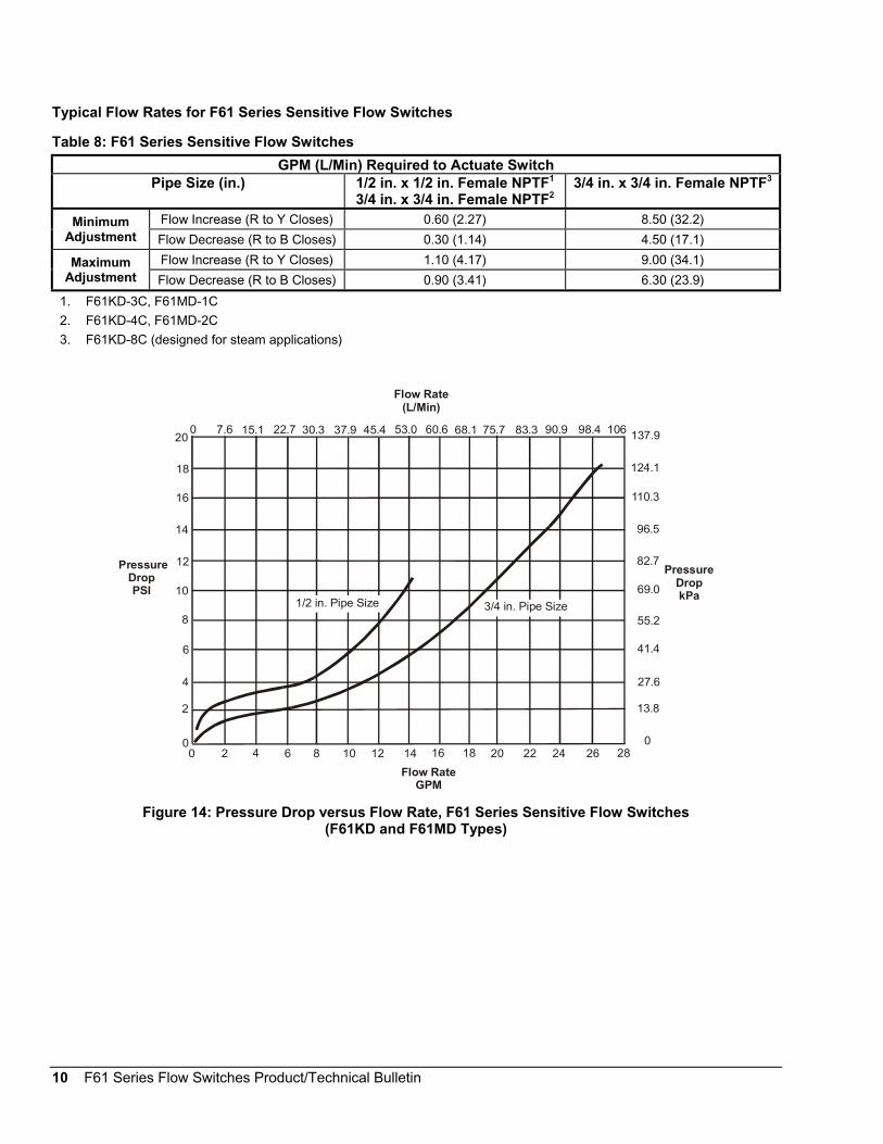
10 F61 Series Flow Switches Product/Technical Bulletin
Typical Flow Rates for F61 Series Sensitive Flow Switches
Table 8: F61 Series Sensitive Flow Switches
GPM (L/Min) Required to Actuate SwitchPipe Size (in.) 1/2 in. x 1/2 in. Female NPTF1
3/4 in. x 3/4 in. Female NPTF23/4 in. x 3/4 in. Female NPTF3
Flow Increase (R to Y Closes) 0.60 (2.27) 8.50 (32.2)MinimumAdjustment Flow Decrease (R to B Closes) 0.30 (1.14) 4.50 (17.1)
Flow Increase (R to Y Closes) 1.10 (4.17) 9.00 (34.1)MaximumAdjustment Flow Decrease (R to B Closes) 0.90 (3.41) 6.30 (23.9)
1. F61KD-3C, F61MD-1C
2. F61KD-4C, F61MD-2C
3. F61KD-8C (designed for steam applications)
0 7.6 15.1 22.7 30.3 37.9 45.4 53.0 60.6 68.1 75.7 83.3 90.9 98.4 106
Flow Rate(L/Min)
0
2
4
6
8
10
12
14
16
18
20 137.9
124.1
110.3
96.5
82.7
69.0
55.2
41.4
27.6
13.8
00 2 4 6 8 10 12 14 16 18 20 22 24 26 28
Flow RateGPM
Pressure DropPSI
Pressure DropkPa
1/2 in. Pipe Size 3/4 in. Pipe Size
Figure 14: Pressure Drop versus Flow Rate, F61 Series Sensitive Flow Switches(F61KD and F61MD Types)

F61 Series Flow Switches Product/Technical Bulletin 11
Checkout
IMPORTANT: Ensure installation, wiring and controlsettings are according to the applicationrequirements. Refer to the controlled system’smanufacturer specifications for the proper settingswhen adjusting these controls.
Apply power to the control and controlled equipment.Cycle the controlled system at least three times atnormal operating conditions.
The circuit between the red and the yellow leads(terminals) closes when sufficient fluid flows throughthe pipe to trip the F61 flow switch.
Repairs and ReplacementField repairs, except for replacement of the cover andpaddles, must not be made. For a replacement flowswitch, paddle kit or cover, contact the nearestJohnson Controls/PENN™ distributor. For moreinformation, contact Refrigeration ApplicationEngineering at (800) 275-5676.
Troubleshooting
Table 9: Troubleshooting
Symptom/Problem SolutionWater (condensate) is within the enclosure. Use a model with a NEMA 3R enclosure. If using a model
with a NEMA 3R enclosure, inspect the grommet in theconduit fitting. Replace grommet if defective.
Fluid from the tank is leaking into enclosure due tobellows failure.
Replace flow switch.
Switch does not activate due to debris caught within theswitch mechanism.
Clear any debris within the switch mechanism. Test theoperation of switch several times for proper operation.
Control switch action is reversed. Ensure connections follow wiring diagrams.
Control does not switch. Check connections.
Switch fails to return to the no flow position. Switch is set lower than the factory setting. Increase thesetting.
On vertical pipes, ensure that direction of flow is up. Thearrow on switch must point in direction of flow (up).
Control does not switch on flow increase. Check for cracked/broken paddle. Replace if necessary.

12 F61 Series Flow Switches Product/Technical Bulletin
Ordering Information
Table 10: F61 Series Standard Flow Switch Models
ProductCode
NumberEnclosure Bellows Paddle
F61KB-11C NEMA 1Stainless Steel; three-piece Paddle (3 in., 2 in., and 1 in. Segments)
Installed; 6 in. Paddle Supplied Uninstalled
F61LB-1CStainless Steel; three-piece Paddle (3 in., 2 in., and 1 in. Segments)
Installed
F61MB-1C
Phosphor Bronze
F61MB-5C Stainless Steel
F61MG-1C*
NEMA 3/NEMA 3R
(Rain-Tight)
Phosphor Bronze
Stainless Steel; three-piece Paddle (3 in., 2 in., and 1 in. Segments)Installed; 6 in. Paddle Supplied Uninstalled
* Gold-Plated Contacts
Table 11: F61 Series Sensitive Flow Switch Models
ProductCode
NumberEnclosure Bellows Inlet and Outlet
F61KD-3C 1/2 in. x 1/2 in. Female NPTF
F61KD-4C
F61KD-8C
NEMA 1 Phosphor Bronze3/4 in. x 3/4 in. Female NPTF
F61MD-1C 1/2 in. x 1/2 in. Female NPTF
F61MD-2CNEMA 3/3R(Rain-Tight)
Stainless Steel3/4 in. x 3/4 in. Female NPTF
Table 12: Replacement Paddle Kits
Product CodeNumber
Description
KIT21A-600 Stainless Steel three-piece Paddle (3 in., 2 in., and 1 in. Segments)
KIT21A-601 Stainless Steel 6 in. Paddle
PLT52A-600R Stainless Steel three-piece Paddle (3 in., 2 in., and 1 in. Segments) and 6 in. Paddle
CVR62A-600R Replacement Cover Assembly for LB, MB, MD and MG types

F61 Series Flow Switches Product/Technical Bulletin 13
Electrical Ratings
Table 13: Electrical Ratings for F61KB, F61 KD, F61LB, F61MB and F61MD Types
Electrical Ratings 120 VAC 208 VAC 240 VAC 277 VACHorsepower 1 1 1 -
Full Load Amperes 16.0 8.8 8.0 -
Locked Rotor Amperes 96.0 52.8 48.0 -
Non-inductive Amperes 16.0 16.0 16.0 16.0
Pilot Duty 125 VA at 24/277 VAC
Table 14: Electrical Ratings for F61MG Types
Electrical Ratings 120 VACFull Load Amperes 1
Locked Rotor Amperes 6
Non-inductive Amperes 2
Pilot Duty 125 VA at 24/277 VAC

14 F61 Series Flow Switches Product/Technical Bulletin
Technical SpecificationsProduct F61 Series Flow Switches
Maximum Fluid Pressure 150 psig (1034 kPa)
Minimum FluidTemperature
32°F (0°C) (F61KB, F61KD, F61LB)
-20°F (-29°C) (F61MB, F61MD, F61MG)
Maximum FluidTemperature
250°F (121°C)
Switch SPDT
Wiring ConnectionsScrew Type Terminals (F61KB, F61KD, F61LB)
Four Color-coded No. 14 AWG Solid Conductor Wire Leads, 7 in. (178 mm) (F61MB,F61MD, F61MG)
Standard 1 in. 11-1/2 NPT ThreadsPipeConnector Sensitive See Table 11.
Conduit ConnectionOne 7/8 in. (22 mm) Hole for 1/2 in. Conduit with 1-1/8 in. (29 mm) Knockout Ring for3/4 in. Conduit (F61KB)
Female Hub for 1/2 in. Conduit, 1/2-14 NPSM Threads (F61LB, F61MB, F61MG)
UL Listed E5368, CCN NMFT
AgencyListings CSA Certified
LR948, Class 3211 06, Class 4813 02, Class 1222 01 (F61KB, F61KD)
(F61LB - Not CSA Certified)
LR948, Class 3211 06 (F61MB, F61MD, F61MG)
Shipping Weight 2.8 lb (1.3 kg)
The performance specifications are nominal and conform to acceptable industry standards. For application at conditions beyond thesespecifications, consult Johnson Controls/Penn Application Engineering at 1-800-275-5676. Johnson Controls, Inc. shall not be liable fordamages resulting from misapplication or misuse of its products.
Controls Group507 E. Michigan StreetP.O. Box 423 Printed in U.S.A.Milwaukee, WI 53201 www.johnsoncontrols.com