Embed Size (px)
Citation preview
8/20/2019 SPE-92980-MS_Controls on Fracturing in Carbonate Rocks
http://slidepdf.com/reader/full/spe-92980-mscontrols-on-fracturing-in-carbonate-rocks 1/6
SPE 92980
Controls on Fracturing in Carbonate RocksD.C.P. Peacock and A. Mann, Fugro Robertson
Copyright 2005, Society of Petroleum Engineers Inc.
This paper was prepared for presentation at the 14th SPE Middle East Oil & Gas Show and
Conference held in Bahrain International Exhibition Centre, Bahrain, 12–15 March 2005.
This paper was selected for presentation by an SPE Program Committee following review ofinformation contained in a proposal submitted by the author(s). Contents of the paper, aspresented, have not been reviewed by the Society of Petroleum Engineers and are subject tocorrection by the author(s). The material, as presented, does not necessarily reflect any posi-tion of the Society of Petroleum Engineers, its officers, or members. Papers presented at SPEmeetings are subject to publication review by Editorial Committees of the Society of PetroleumEngineers. Electronic reproduction, distribution, or storage of any part of this paper for com-mercial purposes without the written consent of the Society of Petroleum Engineers is prohib-ited. Permission to reproduce in print is restricted to a proposal of not more than 300 words;illustrations may not be copied. The proposal must contain conspicuous acknowledgment ofwhere and by whom the paper was presented. Write Librarian, SPE, P.O. Box 833836,Richardson, TX 75083-3836, U.S.A., fax 01-972-952-9435.
Abst ractSedimentology (lithology, sedimentary structures, bed thick-ness, mechanical stratigraphy, the nature of bedding planes),structural geology (tectonic setting, palaeostresses, subsi-dence/uplift history, proximity to faults, position in a fold,timing of structural events, mineralisation, the angle between bedding and fractures) and present-day factors (orientations ofin situ stresses, fluid pressure, perturbation of in situ stresses,depth) can all control the nature and distribution of fractureswithin carbonate rocks. Understanding these factors requires
traditional geological skills, including the analysis of core, borehole images and exposed analogues.
IntroductionMore than half of the World’s hydrocarbon reserves are incarbonate rocks. As these reservoirs become mature, it is be-ing increasingly recognised that fractures play a significantrole in controlling production and water breakthrough. Spe-cific objectives of a fracture study can include the following:
• Understand the fractures in terms of the tectonic history ofthe region.
• Analysis of core, borehole image data, well test data, etc.,
to determine the nature of fractures in reservoir formations.• Determine the role of fractures on hydrocarbon migration,
entrapment and production.• Predict optimum well locations and orientations.• Provide inputs into reservoir simulation models.
Determining the factors that control the nature and distri- bution of fractures is a key to the accomplishment of theseobjectives. This paper reviews the factors that control the na-ture and distribution of fractures within carbonate rocks. Ex-amples are presented from Mesozoic limestones of southernEngland. It is shown that traditional geological skills are ofvital importance in determining the sedimentological, struc-tural and present-day factors that control fractures.
DefinitionsFracture is a general term for a discontinuity, with fractures inrock including faults, veins and joints. Veins are mineral-filledfractures [e.g. 1], are commonly mode I (extension) fractures,and usually form as en echelon segments in a vein array. Joints (or open fractures) are mode I fractures, usually withapertures of less than a few millimetres, across which therehas been no measurable shear displacement [e.g. 2], and thatare not mineral-filled. Veins and joints are mechanically simi-lar [e.g. 3], and so it may be appropriate to consider them to-gether in mechanical analyses. There are, however, importantgeometric, scaling and genetic differences between veins and joints [e.g. 4], so it is commonly unhelpful to group them to-gether or to ignore their differences [5]. This paper deals withthe factors controlling veins and joints, although the sametechniques can be applied to faults.
Factors Controlling Fractures In Carbonate RocksVarious factors have been shown to control the frequency,distribution and nature of fractures in rock. This section liststhese factors and gives key references. It is shown how the
influence of these factors can be determined using careful geo-logical interpretation of core, borehole image or exposed ana-logue data. It must be noted that there are particular problemsin using fracture frequencies from wells that are at a low angleto fractures (e.g. vertical wells intersecting vertical fractures), because there are biases in the sampling of the fracture popula-tion [e.g. 6].
Sedimentological factors. The nature of the rocks is a pri-mary control on fracturing. Sedimentological factors includethe following:
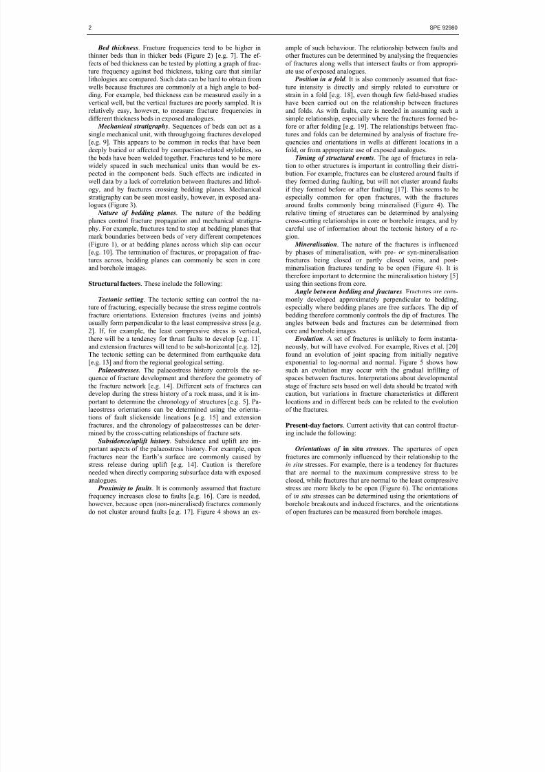
Lithology. Lithological competence can control the nature
of fractures, with more fractures tending to occur in more brit-tle beds (Figure 1) [7]. The control of lithology on fracturingcan be determined by using well data (core, borehole images)or scanlines measured in exposed analogues to determine thenumber of fractures per metre for different lithologies.
Sedimentary structures. Fractures can initiate at such ani-sotropies as bedding plane irregularities and fossils [e.g. 2, 8].Such effects can be difficult to see in core or borehole images because identification relies on the well intersecting an initia-tion point. Such effects are commonly seen, however, in ex- posed analogues.
8/20/2019 SPE-92980-MS_Controls on Fracturing in Carbonate Rocks
http://slidepdf.com/reader/full/spe-92980-mscontrols-on-fracturing-in-carbonate-rocks 2/6
2 SPE 92980
Bed thickness. Fracture frequencies tend to be higher inthinner beds than in thicker beds (Figure 2) [e.g. 7]. The ef-fects of bed thickness can be tested by plotting a graph of frac-ture frequency against bed thickness, taking care that similarlithologies are compared. Such data can be hard to obtain fromwells because fractures are commonly at a high angle to bed-ding. For example, bed thickness can be measured easily in a
vertical well, but the vertical fractures are poorly sampled. It isrelatively easy, however, to measure fracture frequencies indifferent thickness beds in exposed analogues.
Mechanical stratigraphy. Sequences of beds can act as asingle mechanical unit, with throughgoing fractures developed[e.g. 9]. This appears to be common in rocks that have beendeeply buried or affected by compaction-related stylolites, sothe beds have been welded together. Fractures tend to be morewidely spaced in such mechanical units than would be ex- pected in the component beds. Such effects are indicated inwell data by a lack of correlation between fractures and lithol-ogy, and by fractures crossing bedding planes. Mechanicalstratigraphy can be seen most easily, however, in exposed ana-
logues (Figure 3). Nature of bedding planes. The nature of the bedding
planes control fracture propagation and mechanical stratigra- phy. For example, fractures tend to stop at bedding planes thatmark boundaries between beds of very different competences(Figure 1), or at bedding planes across which slip can occur[e.g. 10]. The termination of fractures, or propagation of frac-tures across, bedding planes can commonly be seen in coreand borehole images.
Structural factors. These include the following:
Tectonic setting. The tectonic setting can control the na-ture of fracturing, especially because the stress regime controlsfracture orientations. Extension fractures (veins and joints)usually form perpendicular to the least compressive stress [e.g.2]. If, for example, the least compressive stress is vertical,there will be a tendency for thrust faults to develop [e.g. 11]and extension fractures will tend to be sub-horizontal [e.g. 12].The tectonic setting can be determined from earthquake data[e.g. 13] and from the regional geological setting.
Palaeostresses. The palaeostress history controls the se-quence of fracture development and therefore the geometry ofthe fracture network [e.g. 14]. Different sets of fractures candevelop during the stress history of a rock mass, and it is im- portant to determine the chronology of structures [e.g. 5]. Pa-laeostress orientations can be determined using the orienta-tions of fault slickenside lineations [e.g. 15] and extensionfractures, and the chronology of palaeostresses can be deter-mined by the cross-cutting relationships of fracture sets.
Subsidence/uplift history. Subsidence and uplift are im- portant aspects of the palaeostress history. For example, openfractures near the Earth’s surface are commonly caused bystress release during uplift [e.g. 14]. Caution is thereforeneeded when directly comparing subsurface data with exposedanalogues.
Proximity to faults. It is commonly assumed that fracturefrequency increases close to faults [e.g. 16]. Care is needed,however, because open (non-mineralised) fractures commonlydo not cluster around faults [e.g. 17]. Figure 4 shows an ex-
ample of such behaviour. The relationship between faults andother fractures can be determined by analysing the frequenciesof fractures along wells that intersect faults or from appropri-ate use of exposed analogues.
Position in a fold . It is also commonly assumed that frac-ture intensity is directly and simply related to curvature orstrain in a fold [e.g. 18], even though few field-based studies
have been carried out on the relationship between fracturesand folds. As with faults, care is needed in assuming such asimple relationship, especially where the fractures formed be-fore or after folding [e.g. 19]. The relationships between frac-tures and folds can be determined by analysis of fracture fre-quencies and orientations in wells at different locations in afold, or from appropriate use of exposed analogues.
Timing of structural events. The age of fractures in rela-tion to other structures is important in controlling their distri- bution. For example, fractures can be clustered around faults ifthey formed during faulting, but will not cluster around faultsif they formed before or after faulting [17]. This seems to beespecially common for open fractures, with the fractures
around faults commonly being mineralised (Figure 4). Therelative timing of structures can be determined by analysingcross-cutting relationships in core or borehole images, and bycareful use of information about the tectonic history of a re-gion.
Mineralisation. The nature of the fractures is influenced by phases of mineralisation, with pre- or syn-mineralisationfractures being closed or partly closed veins, and post-mineralisation fractures tending to be open (Figure 4). It istherefore important to determine the mineralisation history [5]using thin sections from core.
Angle between bedding and fractures. Fractures are com-monly developed approximately perpendicular to bedding,especially where bedding planes are free surfaces. The dip of bedding therefore commonly controls the dip of fractures. Theangles between beds and fractures can be determined fromcore and borehole images.
Evolution. A set of fractures is unlikely to form instanta-neously, but will have evolved. For example, Rives et al. [20]found an evolution of joint spacing from initially negativeexponential to log-normal and normal. Figure 5 shows howsuch an evolution may occur with the gradual infilling ofspaces between fractures. Interpretations about developmentalstage of fracture sets based on well data should be treated withcaution, but variations in fracture characteristics at differentlocations and in different beds can be related to the evolutionof the fractures.
Present-day factors. Current activity that can control fractur-ing include the following:
Orientations of in situ stresses. The apertures of openfractures are commonly influenced by their relationship to thein situ stresses. For example, there is a tendency for fracturesthat are normal to the maximum compressive stress to beclosed, while fractures that are normal to the least compressivestress are more likely to be open (Figure 6). The orientationsof in situ stresses can be determined using the orientations of borehole breakouts and induced fractures, and the orientationsof open fractures can be measured from borehole images.
8/20/2019 SPE-92980-MS_Controls on Fracturing in Carbonate Rocks
http://slidepdf.com/reader/full/spe-92980-mscontrols-on-fracturing-in-carbonate-rocks 3/6
SPE 92980 3
Fluid pressure. The relative magnitudes of fluid pressureand in situ stresses can control the initiation of fractures andwhich fractures are open. If fluid pressure exceeds the mini-mum compressive stress, then the effective stress [21] is suchthat effective tension exists in the direction of the least com- pressive stress. Extension fractures (vein and joints) can initi-ate and remain open perpendicular to the direction of the least
compressive stress if the rock is in effective tension. The rela-tionship between in situ stresses and fluid pressure is thereforeof crucial importance in controlling whether fractures are openor closed (Figure 6). Fluid pressure can be determined fromreservoir engineering data, with the orientations of open andclosed fractures giving an indication of the orientations andmagnitudes of the in situ stresses.
Perturbation of in situ stresses. Local variations instresses occur, for example around folds or faults [e.g. 20], andsuch stress perturbations can control the orientations and ge-ometries of fractures. Figure 7 shows and example of jointsthat are perturbed around a fault, these reflecting stress pertur- bation. Stress perturbation in a reservoir is indicated by varia-
tions in the orientations of natural or induced fractures seen incore or borehole images.
Depth. Variations in stresses and fluid pressure occur withdepth [e.g. 22], and so there can be related variations in thenature of the open fractures. Such effects are indicated in welldata by variations in the nature of open fractures with depth.
The Importance Of Geological InterpretationUnderstanding the factors that control fracture geometry, ori-entation, spacing, etc., helps to reduce risk and to improve predictions and modelling. Such knowledge can, for example, be used to plan optimum well locations and orientations. Gooddata and careful geological interpretation are two vital compo-nents of any useful fracture study. Core and borehole imagedata provide direct information about the fractures in a reser-voir, but useful information can also be obtained from reser-voir engineering and seismic data. Statistical analysis of frac-ture data is important, but full interpretation requires tradi-tional geological interpretations, such as the determination ofage relationships between structures. Modelling methods thatdo not use data but rely on simulations (such as populating areservoir with a fracture distribution controlled by curvature),or that are not geologically sensible or realistic, are unlikely to be successful.
Exposed analogues can be useful in developing models,especially if well data are limited. Care is needed, however, because an exposed analogue will have a different geologicalhistory and will be under different conditions than a reservoir.Use of analogue data requires geological knowledge. For ex-ample, Figure 8 shows a zone of closely spaced joints in Cre-taceous Chalk. This example is not a good analogue for the North Sea Chalk fields, which tend to have much higher po-rosities [e.g. 23]. The location can be used, however, to gaininsights into aspects of the carbonate reservoirs on the MiddleEast, where such zones of closely spaced joints are common.For example, this location can be used to test fracture frequen-cies inside and outside of the joint zones, and to measure thespacing between swarms. The careful use of analogues cantherefore provide important insights into subsurface geology.
ConclusionsThe nature and distribution of fractures within carbonate rockscan be controlled by sedimentology (lithology, sedimentarystructures, bed thickness, mechanical stratigraphy, and thenature of bedding planes), structural geology (tectonic setting, palaeostresses, subsidence/uplift history, proximity to faults, position in a fold, timing of structural events, mineralisation,
and the angle between bedding and fractures) and present-dayfactors (orientations of in situ stresses, fluid pressure, pertur- bation of in situ stresses, and depth). Traditional geologicalskills are of great importance in determining the factors thatcontrol fractures and in providing realistic inputs into reservoirsimulation models. The careful geological analysis of core, borehole images and exposed analogues can be used to deter-mine the relative timing of events, and this plays a crucial rolein determining the nature and distribution of fractures. Forexample, open fractures tend to be clustered around faults onlyif the open fractures and faults formed at the same time. Clus-tering does not occur if the open fractures pre-date or post-datethe faults.
AcknowledgementsFugro Robertson is thanked for permission to publish thiswork.
References1. Davis, G.H. and Reynolds, S.J.: Structural Geology of Rocks and
Regions, Wiley, New York (1996).2. Pollard, D.D. and Aydin, A.: “Progress in understanding jointing
over the past century,” Geological Society of America Bulletin(1988) 100, 1181.
3. Thomas, A.L. and Pollard, D.D.: “The geometry of echelon frac-tures in rock: implications from laboratory and numerical ex- periments,” Journal of Structural Geology (1993) 15, 323.
4. Gillespie, P.A. et al.: “Scaling relationships of joint and veinarrays from The Burren, Co. Clare, Ireland,” Journal of StructuralGeology (2001) 23, 183.
5. Peacock, D.C.P.: “Differences between veins and joints using theexample of the Jurassic limestones of Somerset,” In: Cosgrove,J.W. and Engelder, T. (Eds.) The Initiation, Propagation, and Ar-
rest of Joints and Other Fractures, Geological Society of Lon-don, Special Publication (2004) 231, 209.
6. Terzaghi, R.D.: “Sources of errors in joint surveys,” Geotech-nique (1965) 15, 287.
7. Ladeira, F.L. and Price, N.J.: “Relationship between fracturespacing and bed thickness,” Journal of Structural Geology (1981)3, 179.
8. McConaughy, D.T. and Engelder, T.: “Joint interaction with em-
bedded concretions: joint loading configurations inferred from propagation paths,” Journal of Structural Geology (1999) 21,1637.
9. Finn, M.D. et al.: “Kinematics of throughgoing fractures in jointed rocks,” Tectonophysics (2003) 376, 151.
10. Cooke, M.L. and Underwood, C.A.: “Fracture termination andstep-over at bedding interfaces due to frictional slip and interfaceopening,” Journal of Structural Geology (2001) 23, 223.
11. Anderson, E.M.: The Dynamics of Faulting, Oliver and Boyd,Edinburgh (1951).
12. Sibson, R.H.: “Earthquake faulting as a structural process,” Jour-nal of Structural Geology (1989) 11, 1.
13. Reinecker, J et al.: The 2004 release of the World Stress Map.Available online at www.world-stress-map.org (2004).
14. Rawnsley, K.D. et al.: “Jointing in the Mesozoic sediments

8/20/2019 SPE-92980-MS_Controls on Fracturing in Carbonate Rocks
http://slidepdf.com/reader/full/spe-92980-mscontrols-on-fracturing-in-carbonate-rocks 4/6
4 SPE 92980
around the Bristol Channel Basin,” Journal of Structural Geology(1998) 20, 1641.
15. Angelier, J.: “Tectonic analysis of fault slip data sets,” Journal ofGeophysical Research (1984) 89, 5835.
16. Pohn, H.A.: “Joint spacing as a method of locating faults,” Geol-ogy (1981) 9, 258.
17. Peacock, D.C.P.: “The temporal relationship between joints andfaults,” Journal of Structural Geology (2001) 23, 329.
18. Özkaya, S.I.: “CURVAZ––a program to calculate magnitude anddirection of maximum structural curvature and fracture-flow in-dex,” Computers and Geosciences (2002) 28, 399.
19. Silliphant, L.J. et al.: “The state of stress in the limb of the SplitMountain anticline, Utah: constraints placed by transected joints,” Journal of Structural Geology (2002) 24, 155.
20. Rives, T. et al.: “Joint spacing: analogue and numerical simula-tions,” Journal of Structural Geology (1992) 14, 925.
21. Hubbert, M.K. and Rubey, W.: “Role of fluid pressure in me-chanics of over-thrust faulting. Parts I and II,” Bulletin of theGeological Society of America (1959) 70, 115.
22. Sepúlveda, N. and Zack, A.L.: “The effects of overburden stresson the specific storage and hydraulic conductivity of artesian aq-uifers,” Journal of Hydrology (1991) 128, 305.
23. Mallon, A.J. and Swarbrick, R.E.: “A compaction trend for non-reservoir North Sea Chalk,” Marine and Petroleum Geology(2002) 19, 527.
Figure 1. Example of the lithological control on fractures, from theLiassic limestones and shales of Somerset, U.K. More veins and
jo ints occur in the more br it tle limestones than in the less br it tle
shales.
(a)
(b)
Figure 2. Examples of joints on Liassic limestone bedding planes
from Somerset, showing the influence of bed thickness. (a) Bed
80 mm thick. (b) Bed 300 mm thick. Joint frequencies tend to behigher in thi nner beds than in thicker beds [e.g. 7], with differentpatterns of j oint occurr ing in t he different beds.

8/20/2019 SPE-92980-MS_Controls on Fracturing in Carbonate Rocks
http://slidepdf.com/reader/full/spe-92980-mscontrols-on-fracturing-in-carbonate-rocks 5/6
SPE 92980 5
Figure 3. Gently dipping Jurassic limestones at Osmington, Dor-set, U.K. The steeply dipping joints cut across bedding planes,and so there does not appear to be a lithological control on frac-turing.
Figure 4. Oblique view of a Liassic limestone bedding plane cutby a dextral strike-slip fault, Somerset. Calcite veins are clusteredwithin the fault zone, but the later joints are not clustered. Thisexample illustrates the importance of the timing of different frac-tures [ 17].
Figure 5. Schematic diagram of the evolution of fracture spacing.(a) Initial fracture development, with clustered fractures showinga negative exponential distribution. (b) New fractures infill thespaces, producing a log-normal distributi on. (c) The wider spacesare filled by fr actures, producing an approximately equal spacingof fractures and a normalised distributi on. (d) Graphs of the frac-ture spacings shown in (a) to (c).
8/20/2019 SPE-92980-MS_Controls on Fracturing in Carbonate Rocks
http://slidepdf.com/reader/full/spe-92980-mscontrols-on-fracturing-in-carbonate-rocks 6/6
6 SPE 92980
Figure 6. Relationships between the stress system and open frac-tures. (a) All of the fractures will tend to be closed if fluid pressure
(Pf ) is less than the least compressive stress ( 3). (b) One set offractures will tend to be open if the intermediate compressive
stress ( 2) > Pf > 3, these being perpendicular to 3. (c) Open frac-
tures will tend to be perpendicular to 3 if the maximum compres-
sive stress ( 1) > Pf > 2, but can be of an orientation parallel to 1.
(d) Any orientation of fracture can be open if Pf > 1.
Figure 7. Photograph of joints curving i nto a NNE-trending sinis-tral strike-slip fault zone that has tens of millimetres displace-ment, Somerset. Beds have a separation across the fault zonebecause the slip vector is slightly oblique to the gently dippingbeds [ 17].
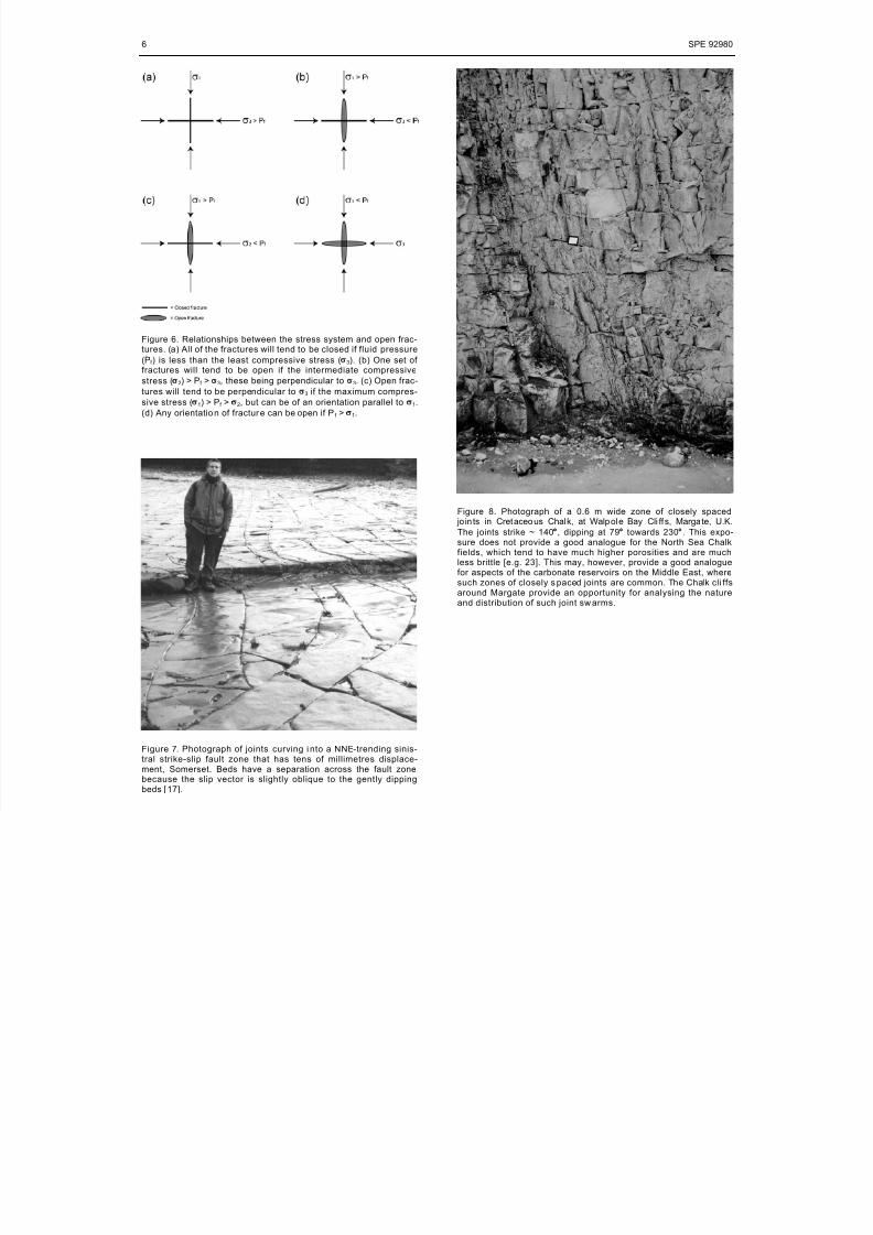
Figure 8. Photograph of a 0.6 m wide zone of closely spaced jo in ts in Cretaceous Chalk, at Walpole Bay Cli ffs, Margate, U.K.
The joints strike ~ 140°, dipping at 79° towards 230°. This expo-sure does not provide a good analogue for the North Sea Chalkfields, which tend to have much higher porosities and are muchless brittle [e.g. 23]. This may, however, provide a good analoguefor aspects of the carbonate reservoirs on the Middle East, wheresuch zones of closely s paced joints are common. The Chalk cli ffsaround Margate provide an opportunity for analysing the natureand distribution of such joint sw arms.