Embed Size (px)
Citation preview

SPE 169064
The Effect of Cr(III) Acetate-HPAM Gel Maturity on Washout from Open Fractures Bergit Brattekås, Stina G. Pedersen, Hilde T. Nistov, Åsmund Haugen, Arne Graue; Dept. of Physics and Technology, University of Bergen, Norway, Jenn-Tai Liang; TORP, University of Kansas, USA and Randall S. Seright; New Mexico Petroleum Recovery Research Center, USA. Copyright 2014, Society of Petroleum Engineers This paper was prepared for presentation at the SPE Improved Oil Recovery Symposium held in Tulsa, Oklahoma, USA, 12–16 April 2014. This paper was selected for presentation by an SPE program committee following review of information contained in an abstract submitted by the author(s). Contents of the paper have not been reviewed by the Society of Petroleum Engineers and are subject to correction by the author(s). The material does not necessarily reflect any position of the Society of Petroleum Engineers, its officers, or members. Electronic reproduction, distribution, or storage of any part of this paper without the written consent of the Society of Petroleum Engineers is prohibited. Permission to reproduce in print is restricted to an abstract of not more than 300 words; illustrations may not be copied. The abstract must contain conspicuous acknowledgment of SPE copyright.
Abstract The blockage performance of a Cr(III) acetate-HPAM gel was investigated using several different application regimes and gel maturities. Fractured core plugs from four outcrop core materials were used, all constituting smooth, longitudinal fractures of 1 mm aperture. Mature and immature gel was placed in the fractures, and for some application regimes in the surrounding core matrix, and the blockage performance assessed by recording rupture pressures and subsequent residual resistance factors during chase waterfloods, Frrw. Placement of mature gel in open fractures yielded consistent rupture pressures during subsequent water injections, following linear trends for given gel placement rates and throughput volumes. The rupture pressures were predictable and stable in all the core materials studied. Rupture pressures achieved after placement and in-situ crosslinking of gelant were comparable to mature gel rupture pressures, but were less predictable. When maximizing gelant saturation in the matrix, rupture pressures were measured to 12 – 53 psi/ft. The maximum achieved rupture pressure when gelant was placed without matrix taps to promote leakoff was 11.9 psi/ft. Interactions between rock material and gelant were observed when Bentheim sandstone cores were used, and gel was in some cases not formed. No such interactions were observed in experiments using formed gel. Significant permeability reduction for water was achieved when both gel and gelant were used. Residual resistance factors for cores treated with gel and gelant were initially comparable. After eight water flushes (>120 fracture volumes (FV) water injected) substantially greater pressure gradients were observed in cores treated with formed gel rather than gelant cross-linked in-situ and the permeability reduction averaged a factor 5000 for gel and 600 for gelant treated cores. The significance of these observations to field applications will be discussed. Introduction High permeability contrasts in fractured reservoirs may cause channeling of injected fluids through fracture networks, contributing to low sweep efficiency and an increased waste stream from excess production of water. The production oil cut may be increased by reducing fracture conductivity (Graue et al. (2002)). Reduction of flow in fractures or high permeability zones after placement of polymer gels have been reported (Seright (1995 and 2003), Sydansk (1990 and 2000), Rousseau (2005), Portwood (1999 and 2005), Willhite and Pancake (2008)).
Polymer gel may be placed in a fracture system as immature gel (gelant) or as pre-formed, mature gel. Gelant has low viscosity and small particles, which enable it to flow through rock matrix as well as fractures (Seright et al. (2003)), and relatively low pressure gradients are required for extrusion. Subjecting gelant to an elevated temperature over time changes the solution properties and form a rigid gel. Mature gel is inhibited from passing through pore throats due to its structure, thus the chemical treatment is contained to open fractures during injection (Seright (2001)). Mature gel has little sensitivity to physiochemical conditions in reservoirs (Zhang and Bai (2011)), while gelant may experience compositional changes when contacting reservoir fluids or rock, that may interfere with gelation (Zou et al. (2000), Ganguly et al. (2002)). Polymer gel resistance to washout from fractures was previously studied after placement of immature and mature gel (Ganguly et al. (2002), Seright (2003), Wilton and Asghari (2007)). Ganguly et al. (2002) placed gelant in fractured cores and slabs, with and without matrix taps to promote leakoff to the matrix. The gel was cross-linked in-situ and the rupture pressure measured during subsequent brine injection. Ganguly et al. argue that gelant penetrates both the fracture and adjacent rock matrix during injection, thus forming a zone of homogeneous concentrated gel. This creates a gripping effect between gel in the fracture and matrix that may increase the overall pressure resistance of the gel. They did not achieve gelation (cross-linking

2 SPE 169064
to form rigid gel) when gelant was placed in the fracture without penetrating the adjacent matrix, presumably due to diffusion of chromium through the porous rock. Wilton and Asghari (2007) achieved in-situ gelation without gelant leakoff to the matrix by pre-flushing the core with chromium solution, or by placing gelant with an increased amount of chromium in the fracture (chromium overload). Seright (1995, 1999, 2001 and 2003) and Seright et al. (1998 and 2003) showed that pre-formed gel dehydrates during propagation through a fracture. During the leakoff process, solvent leaves the gel and proceeds through the matrix. The high concentration gel left in the fracture is more rigid and has a higher pressure resistance than gel of injected composition. Wormholes through the concentrated gel contain fresh gel which may be readily mobilized. Seright (2003) injected mature gel into 1 mm fractures and recorded rupture pressures during subsequent injection of brine or oil.
In previous work fracture apertures, experimental setups and measured gel resistance to washout varied. This study aimed to reproduce and improve results through core studies. We used four outcrop rock materials, constituting a total of 37 core plugs to study rupture pressures after placement of gelant cross-linked in-situ, and mature gel in open fractures. The unified method of core assembly, comparable core dimensions and experimental setups, as well as repeated experiments, enabled us to directly compare results on gel blocking ability after placement of immature and mature gel in fractures. Experiments Two polymer gel placement methods were investigated, and are discussed separately below: 1) mature gel injection into fractured core plugs and 2) injection of gelant solution or direct gelant saturation of fractured cores under vacuum. The rupture pressure was defined as “the highest initial pressure response observed at low flow rate before brine breakthrough occurs“ (Wilton and Asghari (2007)) and was measured by injecting water at the core inlet until the gel in the fracture ruptured and gel and/or water was produced out the fracture outlet. A sharp drop in differential pressure was usually observed at the gel rupture point. FluidsThe aqueous gel/gelant used was a 0.5% 5-million-Mw HPAM, cross-linked by 0.0417% Cr(III) acetate. The gel was aged for 24 hours (5X gel time) at 41°C either before or after placement in fractured core plugs. The solvent was synthetic Ekofisk brine (4 wt% NaCl, 0.5 wt% MgCl2·6H2O and 3.4 wt% CaCl2·2H2O). CoreMaterialThe core materials used were Bentheim (Klein and Reuschlè (2003), Schutjens (1995)) or Berea sandstone (Churcher et al. (1991)), Edwards limestone (Ekdale and Bromley (1993), Tipura (2008), Riskedal (2008)) and Portland chalk (Hjuler (2007)). The cores were cut using a band saw, to simulate smooth longitudinal fractures through the core plugs. A constant 1 mm fracture aperture was created by placing POM (polyoxymethylene) spacers at the top and bottom of the fracture during core assembly. The core plugs were fitted with POM end pieces and in some cases matrix taps, and coated in several layers of epoxy. The core plugs were saturated with Ekofisk brine or gelant under vacuum and the porosity and pore volume calculated from weight measurements. MaturegelexperimentsVarying volumes of formed gel was injected into 16 fractured core plugs, using injection rates ranging between 6 – 200 ml/h. An overview of the core properties and associated injection rates may be found in Table 1 and the core setup used during flooding is shown in Figure 1.1). Gel injection was performed at ambient temperature or an elevated temperature of 41oC. These temperature differences do not affect the gel behavior in terms of e.g. leakoff (Seright (2003)). The core plugs were shut in for 24 hours at ambient temperature after gel injection.
To measure the blocking ability of the gel, given by the rupture pressure, brine was injected at the inlet end of the core plugs using a constant rate of 6 ml/h (equivalent to 0.23-0.42 ft/D if all flow was through the matrix and equivalent to 9.2-12.4 ft/D if all flow was only through the fracture). The differential pressure was logged and the rupture pressure recorded at the time of gel rupture, where the passage of fluids through the gel-filled fracture resumed. All matrix taps were closed during water injection. In chosen core plugs, water injection continued to establish a steady state and the pressure gradient was recorded. The water injection rate was thereafter adjusted stepwise and pressure gradients recorded for each rate. The maximum injection rate during brine injection was 600 ml/h (equivalent to 23-42 ft/D if all flow was through the matrix and equivalent to 922-1240 ft/D if all flow was only through the fracture) due to pumping capacity limitations. Immaturegel(gelant)experimentsGelant was injected into 21 fractured core plugs at ambient temperature using a constant injection rate of 30 ml/h and a variety of injection schemes to control the gelant saturation in the core: Saturation Scheme 1: The core setup is shown in Figure 1.1. Initially, the matrix taps at the outlet end were open and the fracture outlet closed. This allowed gelant to partly flood the matrix during injection, although a gradient in gelant saturation will exist through the core. Gelant was injected until breakthrough was observed from both matrix taps. The matrix taps were then closed and the outlet opened, and gelant was injected through the fracture until breakthrough at the outlet. Saturation Scheme 2: The core setup was improved by placing matrix taps in the middle of each matrix half, as shown in

SPE 169064 3
Figure 1.2. Gelant was injected through the top matrix tap until breakthrough at both ends of the fracture, the fracture inlet and outlet were closed and injection continued until gelant breakthrough in the lower matrix tap. Saturation Scheme 3: To ensure maximum penetration of gelant to the matrix, matrix taps were placed at the inlet, middle and outlet of each core half. Gelant was injected as shown in Figure 1.3: (I) through the inlet matrix tap of one core half to the outlet matrix half of the other core half, (II) through the other inlet matrix tap to the opposite outlet matrix tap, and (III) following the core setup in Saturation Scheme 2. Saturation Scheme 4: The core plugs were saturated directly with gelant under vacuum. The partially or fully gelant saturated core plugs were placed in an oven at 40 – 48oC for 24 hours (five times the gelation time) to allow gelation. They were then cooled to ambient temperature, and water was injected at 6 ml/h until the gel ruptured and the rupture pressure was recorded. All matrix taps were closed during water injection. In some cases, water injection continued and the pressure differential across the fracture was recorded for several increasing and\or decreasing rates at steady states. A total of 21 cores were subjected to gelant testing, and their core properties are given in Table 2.
13 cores (Core E to Core Q) were tested a second time immediately following the first test. Gelant was placed in the fracture only, without open matrix taps to promote leakoff, and gelation allowed in-situ. This was done to ensure limited interactions with the rock matrix during second time gelant placement, and to investigate the rupture pressure achieved without gelant leakoff. The same waterflooding procedure was followed.
Figure 1: 1) Core setup used for mature and immature gel injection, 2) setup for improved gelant injection, and 3) further improvement of setup for gelant injection to ensure maximum penetration of the matrix. Table 1: Cores for mature gel injection. Composite cores are half Bentheim sandstone (Bentheim SS) and half Portland chalk.
Core ID
Material Length
[cm] Diameter
[cm] Porosity
[%]
Pore volume
[ml]
Gel throughput
[FV]
Gel injection
rate [ml/h]
Rupture pressure [psi/ft]
1 Bentheim SS 10.27 3.80 22.77 26.52 20.77 6 73.36
2 Portland chalk 10.01 3.81 45.19 55.75 98.25 6 13.48
3 Bentheim SS 10.12 3.81 27.55 31.62 105.47 6 20.05
4 Composite core 5.75 5.08 44.55 52.33 6.14 60 3.25
5 Bentheim SS 14.01 5.08 25.54 72.47 37.11 60 7.76
6 Bentheim SS 13.98 5.08 25.61 72.66 41.46 60 8.17
7 Bentheim SS 14.83 5.11 22.19 68.49 85.15 60 6.09
8 Bentheim SS 14.80 5.11 26.06 80.59 117.90 60 13.10
9 Portland chalk 7.15 5.08 44.91 65.59 197.12 60 36.35
10 Bentheim SS 9.49 3.80 22.72 24.46 4.00 180 6.61
11 Bentheim SS 14.15 5.04 25.61 72.66 41.55 180 6.68
12 Bentheim SS 14.65 5.08 24.03 72.15 81.38 180 14.56
13 Portland chalk 8.00 4.82 48.00 69.90 3.20 200 8.68
14 Bentheim SS 14.52 5.11 24.75 75.11 80.11 200 6.75
15 Composite core 14.02 3.80 34.03 54.10 178.51 200 15.12
16 Composite core 9.76 3.80 36.72 40.65 248.28 200 14.73

4 SPE 169064
Table 2: Cores for gelant placement and in-situ cross-linking.
Core ID
Material Length
[cm] Diameter
[cm] Porosity
[%]
Pore volume
[ml]
Saturation scheme
Rupture pressure,
PR [psi/ft]
Second Rupture pressure,
PR [psi/ft]
A Bentheim SS 14.00 5.08 25.8 73.23 1 0.63 NM
B Bentheim SS 14.00 5.08 22.9 64.93 1 0.21 NM
C Bentheim SS 14.00 5.08 24.1 68.37 1 NA NM
D Bentheim SS 14.00 5.08 18.4 52.24 1 NA NM
E** Bentheim SS 14.87 5.11 22.7 70.53 2 0.62 0.56*
F Bentheim SS 14.91 5.11 23.5 73.40 2 0.36* 0.50*
G Bentheim SS 14.92 5.12 22.1 76.71 2 0.07* 3.18
H Edwards LS 7.19 5.08 26.5 39.35 3 3.63 3.71
I Edwards LS 7.21 5.10 28.3 41.70 3 15.03 3.71
J Edwards LS 7.16 5.12 24.9 37.21 3 12.38 8.84
K Edwards LS 7.17 5.10 26.5 38.93 3 6.19 7.96
L Bentheim SS 15.13 5.11 21.7 68.89 4 0.18* 1.02
M Bentheim SS 14.97 5.08 23.5 73.31 4 2.61 1.15
N Bentheim SS 14.99 5.08 24.0 74.91 4 0.14* 0.44
O Berea SS 7.36 4.94 22.1 31.61 4 12.38 11.94
P Berea SS 7.13 4.97 32.6 45.32 4 16.80 7.52
Q Berea SS 7.23 4.99 26.4 37.24 4 26.97 3.80
R Edwards LS 7.16 4.92 29.0 39.56 4 53.05 NM
S Edwards LS 7.18 4.90 29.7 40.40 4 25.64 NM
T Edwards LS 7.16 4.91 29.1 39.33 4 14.59 NM
U Edwards LS 7.19 4.93 28.0 38.51 4 17.68 NM NA = Not Achieved NM = Not Measured *the rupture pressure was not clearly defined. The value given is the highest pressure obtained during water injection using the lowest rate. ** Core E was flooded with 0.0417% Cr(III)- acetate solved in water before gelant injection.
Results and Discussion MatureGelExperimentsThe measured leakoff rates during gel injection are shown in Figure 2.1, and the pressure gradients are shown in Figure 2.2. The leakoff rates corresponded with the filtercake model (Seright (2003)) for injection rates ≥ 200 ml/h. For gel injection rates ≤ 60 ml/h, leakoff rates fell below the filter cake model, and, using the lowest injection rate of 6 ml/h, the leakoff rate was linear until gel breakthrough at the fracture outlet, at which point it decreased abruptly and was thereafter measured to be a lower parallel to the filtercake model. In cores 1, 4, 10 and 13 gel was only injected until breakthrough at the outlet end of the fracture, and the leakoff rates were therefore not measured. The achieved differential pressure gradients during gel flood were between 3.5 and 14 kPa/cm, and did not depend on gel injection rate (as previously shown by Seright (2003)). The time it took for the pressure to build up to plateau did, however, vary based on injection rate and was approximately 0.2 hours for 200 ml/h injection rate, 1 hour for 60 ml/h and 14 hours using a low gel injection rate of 6 ml/h.
After gel injection, the cores were shut in for 24 hours. Brine was thereafter injected at a lower, constant rate of 6 ml/h and the rupture pressure recorded. Rupture pressures from 3.3 psi/ft to 73.4 psi/ft were measured, and observed to vary based on gel placement rate and gel throughput. Figure 3 shows the rupture pressure measurement for Core 2. The defined pressure drop corresponded with rupture of the gel and production of fluids from the fracture outlet.

SPE 169064 5
Figure 2: 1) Measured leakoff rates during mature gel injection in fractured core plugs. 2) Differential pressure gradients during gel injection. The red square illustrates rate dependency: the plateau differential pressure is not influenced by gel injection rate, but it takes a longer time period to build up to the plateau when the injection rate is lower.
Figure 3: Rupture pressure for Core 2. The distinct pressure drop at t≈60 min corresponded with rupture of the gel and production of fluids from the fracture outlet. All measured rupture pressures following mature gel injection and shut-in are shown in Figure 4. Increasing rupture pressures with gel throughput were observed for the specific gel injection rates. A lower rate generally yielded a higher rupture pressure at the same number of gel fracture volumes (FV) injected. The trend was clearer after injection of several fracture volumes of gel and not evident when gel was injected until breakthrough only. It took 3.2 FV, 4.0 FV, 6.1 FV and 20.8 FV of gel to reach the fracture outlet when the injection rates were 200 ml/h, 180 ml/h, 60 ml/h and 6 ml/h, respectively. The recorded rupture pressures after shut-in were 8.68 psi/ft, 6.01 psi/ft, 3.25 psi/ft and 73.36 psi/ft. The high rupture pressure measured after filling the fracture with gel at 6 ml/h was not reproduced by increasing the gel throughput at this injection rate.
Figure 5 shows the rupture pressures achieved, and the linear trends between measured rupture pressures and injected gel volumes, when gel placement rates were held constant at 60 ml/h (Figure 5.1) and 200 ml/h (Figure 5.2), respectively, and gel throughput varied.
Figure 4: Rupture pressure as a function of fracture volumes (FV) injected.
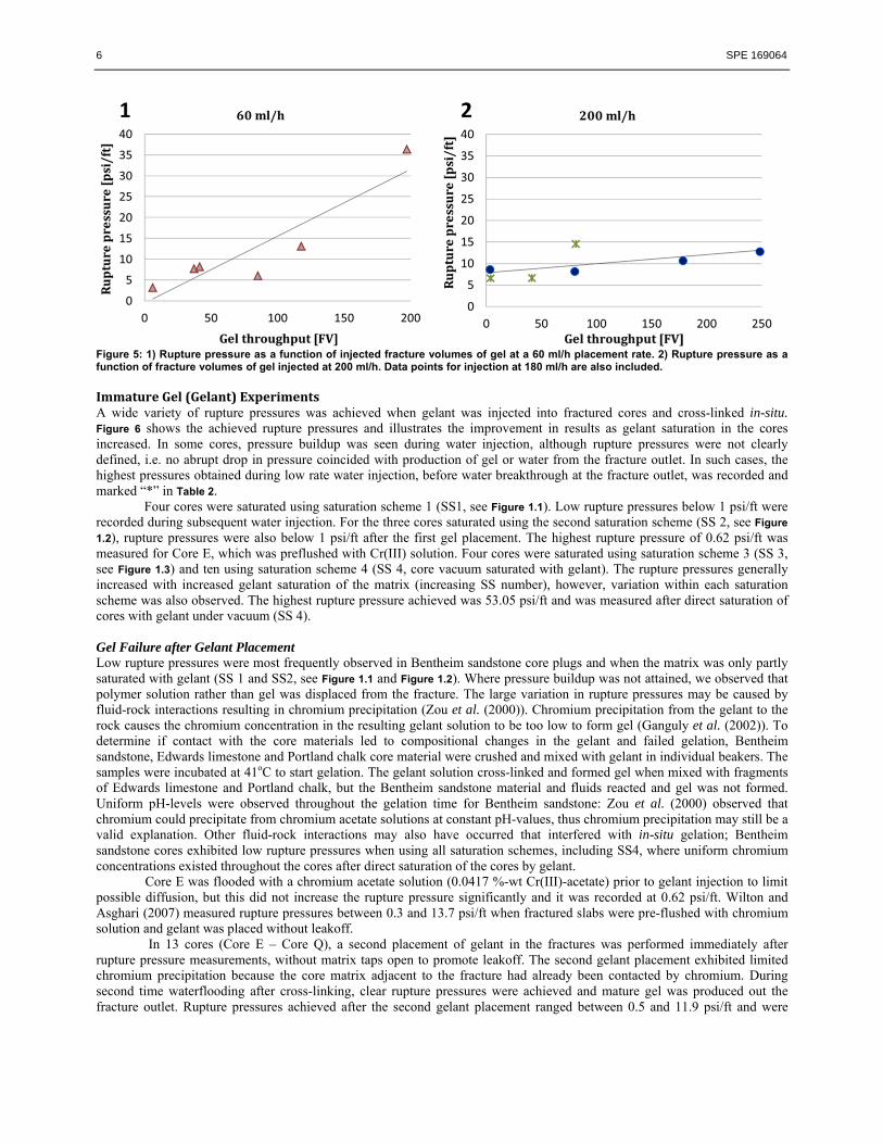
6 SPE 169064
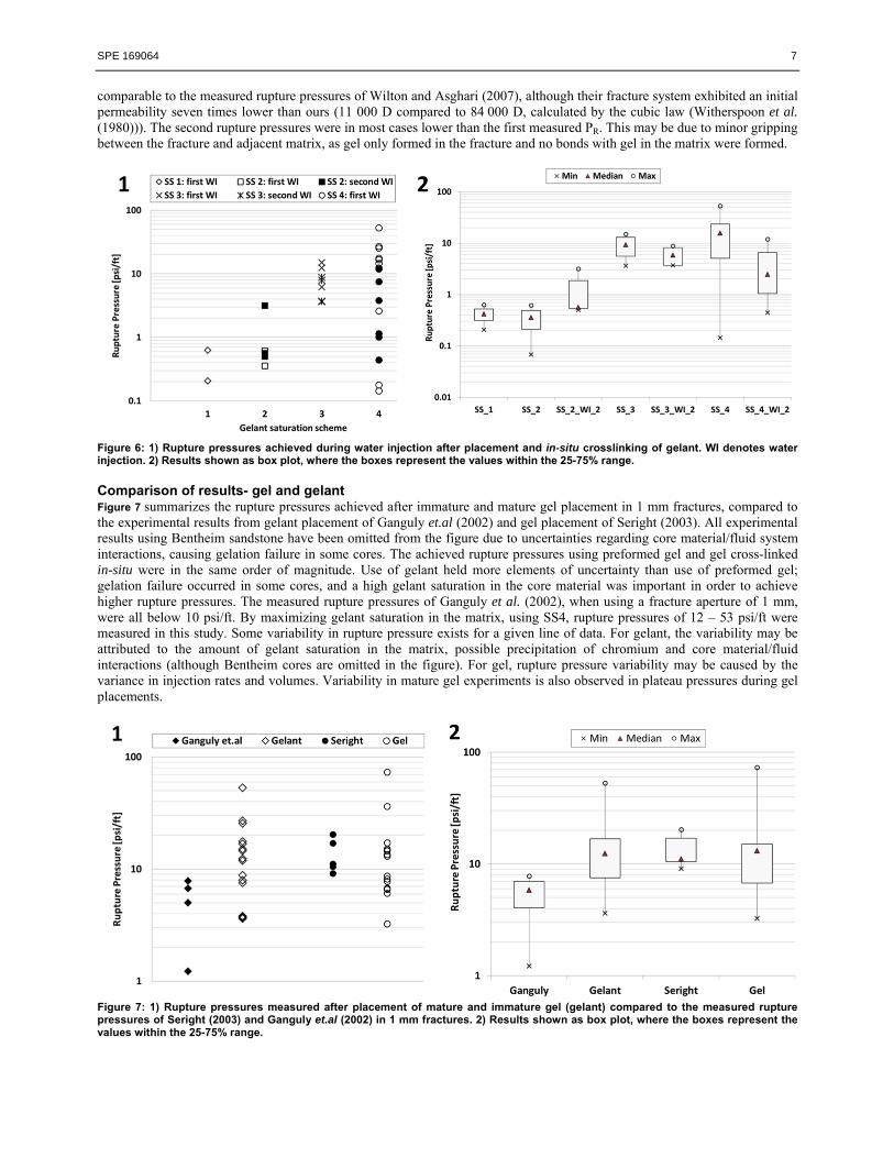
Figure 5: 1) Rupture pressure as a function of injected fracture volumes of gel at a 60 ml/h placement rate. 2) Rupture pressure as a function of fracture volumes of gel injected at 200 ml/h. Data points for injection at 180 ml/h are also included. ImmatureGel(Gelant)ExperimentsA wide variety of rupture pressures was achieved when gelant was injected into fractured cores and cross-linked in-situ. Figure 6 shows the achieved rupture pressures and illustrates the improvement in results as gelant saturation in the cores increased. In some cores, pressure buildup was seen during water injection, although rupture pressures were not clearly defined, i.e. no abrupt drop in pressure coincided with production of gel or water from the fracture outlet. In such cases, the highest pressures obtained during low rate water injection, before water breakthrough at the fracture outlet, was recorded and marked “*” in Table 2.
Four cores were saturated using saturation scheme 1 (SS1, see Figure 1.1). Low rupture pressures below 1 psi/ft were recorded during subsequent water injection. For the three cores saturated using the second saturation scheme (SS 2, see Figure
1.2), rupture pressures were also below 1 psi/ft after the first gel placement. The highest rupture pressure of 0.62 psi/ft was measured for Core E, which was preflushed with Cr(III) solution. Four cores were saturated using saturation scheme 3 (SS 3, see Figure 1.3) and ten using saturation scheme 4 (SS 4, core vacuum saturated with gelant). The rupture pressures generally increased with increased gelant saturation of the matrix (increasing SS number), however, variation within each saturation scheme was also observed. The highest rupture pressure achieved was 53.05 psi/ft and was measured after direct saturation of cores with gelant under vacuum (SS 4). Gel Failure after Gelant Placement Low rupture pressures were most frequently observed in Bentheim sandstone core plugs and when the matrix was only partly saturated with gelant (SS 1 and SS2, see Figure 1.1 and Figure 1.2). Where pressure buildup was not attained, we observed that polymer solution rather than gel was displaced from the fracture. The large variation in rupture pressures may be caused by fluid-rock interactions resulting in chromium precipitation (Zou et al. (2000)). Chromium precipitation from the gelant to the rock causes the chromium concentration in the resulting gelant solution to be too low to form gel (Ganguly et al. (2002)). To determine if contact with the core materials led to compositional changes in the gelant and failed gelation, Bentheim sandstone, Edwards limestone and Portland chalk core material were crushed and mixed with gelant in individual beakers. The samples were incubated at 41oC to start gelation. The gelant solution cross-linked and formed gel when mixed with fragments of Edwards limestone and Portland chalk, but the Bentheim sandstone material and fluids reacted and gel was not formed. Uniform pH-levels were observed throughout the gelation time for Bentheim sandstone: Zou et al. (2000) observed that chromium could precipitate from chromium acetate solutions at constant pH-values, thus chromium precipitation may still be a valid explanation. Other fluid-rock interactions may also have occurred that interfered with in-situ gelation; Bentheim sandstone cores exhibited low rupture pressures when using all saturation schemes, including SS4, where uniform chromium concentrations existed throughout the cores after direct saturation of the cores by gelant.
Core E was flooded with a chromium acetate solution (0.0417 %-wt Cr(III)-acetate) prior to gelant injection to limit possible diffusion, but this did not increase the rupture pressure significantly and it was recorded at 0.62 psi/ft. Wilton and Asghari (2007) measured rupture pressures between 0.3 and 13.7 psi/ft when fractured slabs were pre-flushed with chromium solution and gelant was placed without leakoff. In 13 cores (Core E – Core Q), a second placement of gelant in the fractures was performed immediately after rupture pressure measurements, without matrix taps open to promote leakoff. The second gelant placement exhibited limited chromium precipitation because the core matrix adjacent to the fracture had already been contacted by chromium. During second time waterflooding after cross-linking, clear rupture pressures were achieved and mature gel was produced out the fracture outlet. Rupture pressures achieved after the second gelant placement ranged between 0.5 and 11.9 psi/ft and were
SPE 169064 7
comparable to the measured rupture pressures of Wilton and Asghari (2007), although their fracture system exhibited an initial permeability seven times lower than ours (11 000 D compared to 84 000 D, calculated by the cubic law (Witherspoon et al. (1980))). The second rupture pressures were in most cases lower than the first measured PR. This may be due to minor gripping between the fracture and adjacent matrix, as gel only formed in the fracture and no bonds with gel in the matrix were formed.
Figure 6: 1) Rupture pressures achieved during water injection after placement and in-situ crosslinking of gelant. WI denotes water injection. 2) Results shown as box plot, where the boxes represent the values within the 25-75% range. Comparison of results- gel and gelant Figure 7 summarizes the rupture pressures achieved after immature and mature gel placement in 1 mm fractures, compared to the experimental results from gelant placement of Ganguly et.al (2002) and gel placement of Seright (2003). All experimental results using Bentheim sandstone have been omitted from the figure due to uncertainties regarding core material/fluid system interactions, causing gelation failure in some cores. The achieved rupture pressures using preformed gel and gel cross-linked in-situ were in the same order of magnitude. Use of gelant held more elements of uncertainty than use of preformed gel; gelation failure occurred in some cores, and a high gelant saturation in the core material was important in order to achieve higher rupture pressures. The measured rupture pressures of Ganguly et al. (2002), when using a fracture aperture of 1 mm, were all below 10 psi/ft. By maximizing gelant saturation in the matrix, using SS4, rupture pressures of 12 – 53 psi/ft were measured in this study. Some variability in rupture pressure exists for a given line of data. For gelant, the variability may be attributed to the amount of gelant saturation in the matrix, possible precipitation of chromium and core material/fluid interactions (although Bentheim cores are omitted in the figure). For gel, rupture pressure variability may be caused by the variance in injection rates and volumes. Variability in mature gel experiments is also observed in plateau pressures during gel placements.
Figure 7: 1) Rupture pressures measured after placement of mature and immature gel (gelant) compared to the measured rupture pressures of Seright (2003) and Ganguly et.al (2002) in 1 mm fractures. 2) Results shown as box plot, where the boxes represent the values within the 25-75% range.

8 SPE 169064
Continued Waterflooding after Gel Rupture In Core 3 (PR=20.1 psi/ft) and Core P (PR=16.8 psi/ft) water injection was continued after the rupture pressure was reached, and the differential pressure recorded at steady states for several injection rates. The injection rate was stepwise increased and thereafter decreased through eight flushes. A flush is here defined as one full sequence of rates, decreasing (starting at the maximum rate) or increasing (starting at the minimum rate). Figure 8.1 shows the rate sequences and corresponding measured differential pressure for Core 3 (mature gel), and Figure 8.2 shows the injection rates and measured differential pressure across Core P (gelant cross-linked in-situ). The differential pressures are normalized to the respective rupture pressure of each core, for improved comparison.
Figure 8: 1) Rate and differential pressure for Core 3 during water injection after gel injection and shut-in, and 2) Rate and differential pressure of Core P after gelant injection and in-situ crosslinking. The differential pressures are normalized to the respective rupture pressures in each core. The maximum pressure gradients measured during water injection at specific rates; 6 ml/h, 60 ml/h, 300 ml/h and 600 ml/h are represented in Figure 9 as functions of the effective brine velocity through the fracture. The pressure gradients in both cores decreased for the first two rates in the first flush (increasing rate), and the decrease was most prominent in Core P. The pressure gradient decreased further during the 2nd and 3rd water flushes. After the third flush, pressure gradients for Core 3 remained stable for injection rates >6 ml/h. Stabilization of the system at 6 ml/h took longer time, and the recorded pressure gradient may vary according to how long the system was maintained at the lower rate before proceeding with the next flush. The decrease in pressure gradients was expected and attributed to erosion of gel in the wormholes during water injection. Stable pressure gradients for the higher specific rates suggests that erosion of gel was minor and even higher rates would be required to further erode the gel around the wormholes. For Core P, pressure gradients continued to decrease with water throughput, although the pressure gradient was fairly stable for the highest specific rate after the second flush.
After water injection, the cores were taken apart and the fracture surfaces of Core 3 revealed several wormholes through concentrated gel. Core P fracture surfaces were coated with a thin layer of uniform gel. It is believed that the fracture was initially filled with low-concentration gel, and gradually opened to flow when the gel dehydrated (Krishnan et al. (2000)) or was flushed out by water.
Figure 10 shows the pressure gradients for the specific injection rates as functions of water throughput during the 5th water flush of Core 3 and Core P, after the pressure gradients had stabilized in both cores. The achieved pressure gradients were higher in Core 3 (mature gel) compared to Core P (gelant) for all rates; a higher pressure gradient was reached in Core 3 using the low injection rate of 6 ml/h than using an injection rate a hundred times higher, 600 ml/h, in Core P. The substantially greater pressure resistance of mature gel after rupture, and significant throughput of water, may be explained by the elasticity of the gel, allowing its wormholes to collapse and re-open during waterflooding at the given rates. The effective channel width open to flow, i.e. the wormhole size, in Core 3 during water injection was calculated from (Seright (2003)):
(1)
where Ww is the channel width open to flow, G’ is the elastic modulus of the gel and (dP/dl) is the experimentally measured pressure gradient. The calculated Ww is shown in Figure 11.1. Figure 11.2 shows calculated wormhole size from pressure data at specific rate 60 ml/h and illustrates the general behavior; wormhole size initially increased, and thereafter stabilized at a close to constant value for several flushes. Continued erosion of wormholes with water throughput was not observed for mature gel after the first few flushes, thus an increase in flow channel width was reversible at the given rates. The gradual opening of a fracture during waterflooding after placement, and rupture, of immature gel was largely irreversible.

SPE 169064 9
Figure 9: The pressure gradient plotted against the effective velocity through the fracture for both gel and gelant. Flushes with decreasing rate steps are shown with dotted lines. The residual resistance factor to water, Frrw, gives the relationship between water mobility in the fracture before and after gel placement. Frrw values were calculated for Core 3 and Core P waterfloods and are given in Figure 12.1 as a function of time and Figure 12.2 as a function of injection rate. Permeability of the fractures before gel treatment was calculated from the cubic law (Witherspoon et al. (1980)), and permeability of the system after gel placement was calculated by the pressure drop across the fracture. The residual resistance factors for the cores are initially comparable and both decrease some with water throughput, but Frrw for Core P decreases faster than for Core 3. After the 8th water flush, the permeability reduction in Core 3 (128 FV of water injected) averaged a factor of 5000 and Core P (170 FV of water injected) averaged a factor 600. Large scale variations in system permeability were seen with variations in injection rate. This is expected behavior owed to the elastic nature of the gel (Wilton and Asghari (2007)).
Figure 10: Pressure gradients for specific injection rates as a function of water throughput for the 5th water flush of Core 3 and Core

10 SPE 169064
P.
Figure 11: 1) The effective channel width open to flow during water injection. 2) Effective channel width for specific rate 60 ml/h. Significance to Field Applications The experiments performed in this study showed that the rupture pressures achieved after gel treatment using either gelant cross-linked in-situ or formed gel may be in the same order of magnitude. However, injection of gelant holds more elements of uncertainty than injection of preformed gel; interactions between the fluids and rock material caused gelation failure in some cores, especially where gelant saturation in the matrix was limited. Ganguly et.al (2002) proposed that gelation could not occur in fractures if leakoff of gelant to the fracture adjacent matrix was not attained. Wilton and Asghari (2007) showed that leakoff of gelant to the matrix was not necessary, and gel could form if the near fracture area was preflushed with chromium or when gelant was placed in the fracture with chromium overload. Second time gelant placement in this study supports their findings, as gel formed in the fracture without matrix taps to promote leakoff.
If cross-linking after gelant placement is dependent on matrix pre-flush or intrusion of gelant to the fracture adjacent matrix during placement, matrix properties will partly control the success of a gel treatment when injection gelant in a fractured system. Reservoirs with high permeable fractures between connected wells, oil-wet preferences etc., where the matrix entry pressure is high compared to the differential pressure reached during gelant injection, or where pore throats are too narrow to allow gelant penetration, may be particularly challenging and call for use of preformed gel. Placement of preformed gel in open fractures yielded consistent results and chemical interactions between fluids and rock material was not observed. Mature and immature gel placement (and cross-linking) in the presence of oil saturated rock, at different wettabilities should be investigated.
Figure 12: 1) Residual resistance factor to water for Core 3 and Core P at different specific rates. 2) Residual resistance factor to water as a function of injection rate.
Conclusions Placement of mature gel in open fractures yielded consistent rupture pressures during subsequent water injections,
following linear trends for given gel placement rates and throughput volumes.
SPE 169064 11
Rupture pressures achieved after placement and in-situ crosslinking of gelant were comparable to mature gel rupture pressures, but were less predictable. When maximizing gelant saturation in the matrix, rupture pressures were measured to 12 – 53 psi/ft.
The maximum achieved rupture pressure when gelant was placed without matrix taps to promote leakoff was 11.9 psi/ft.
Interactions between rock material and gelant were observed when Bentheim sandstone cores were used. No such interactions were observed in experiments using formed gel.
Gel placed in fractures limited permeability to water after rupture when placed as both gel and gelant. Residual resistance factors for cores treated with gel and gelant were initially comparable. After 8 water flushes (>120 FV water injected) substantially greater pressure gradients were observed in cores treated with formed gel rather than gelant cross-linked in-situ and the permeability reduction averaged a factor 5000 for gel and 600 for gelant treated cores.
Acknowledgements The authors wish to thank Stephen J. Johnson and Karen Peltier at TORP (KU), and Kathryn Wavrik at PRRC (NMT) for guidance and help during experiments. The authors at the Dept. of Physics and Technology, University of Bergen, are grateful to the Norwegian research counsil (NFR) for financial support. Nomenclature Frrw= Residual Resistance factor to water PR = Rupture pressure FV = Fracture volume PV = Pore volume SS = Saturation scheme [number] Ww = Wormhole size (channel width open to flow) G’ = Elastic modulus of the gel dP/dL = Experimentally measured pressure gradient WI = Water injection NA = Not achieved NM = Not measured References Churcher, P.L., French, P.R., Shaw, J.e., Schramm, L.L.; “Rock Properties of Berea Sandstone, Baker Dolomite, and Indiana
Limestone”, SPE International Symposium on Oilfield Chemistry, Anaheim, CA, February 20 – 22, 1991.Ekdale, A.A., Bromley, R.G.: “Trace Fossils and Ichnofabric in the Kjølby Gaard Marl, Uppermost Cretaceous, Denmark”,
Bull Geol. Soc. Denmark, Vol. 31, p. 107 – 119, 1993. Ganguly, S., Willhite, G.P., Green, D.W., McCool, C.S.; The Effect of Fluid Leakoff on Gel Placement and Gel Stability in
Fractures”, SPE Journal, Sept. 2002. Graue, A., Nesse, K., Baldwin, B.A., Spinler, E.A. and Tobola, D.; “Impact of Fracture Permeability on Oil Recovery in
Moderately Water-Wet Fractured Chalk Reservoirs”, SPE 75165, presented at SPE/DOE Improved Oil Recovery Symposium, Tulsa, USA, 13– 17 April 2002.
Hjuler, M.L.; “Diagenesis of Upper Cretaceous onshore and offshore chalk from the North Sea area”, PhD thesis from the technical University of Denmark, 2007.
Klein, E., Reuschle, T.: “A Model for the Mechanical Behaviour of Bentheim Sandstone in the Brittle Regime”, 2003, Pure appl. Geophys. 160, p. 833 – 849
Krishnan, P., Asghari, K., Willhite, G.P., McCool, C.S., Green, D.W. and Vossoughi, S.; “Dehydration and Permeability of Gels Used in In-Situ Permeability Modification Treatments”, SPE 59347, presented at SPE/DOE Improved Oil Recovery Symposium, Tulsa, 3 – 5 April 2000.
Portwood, J.T.; “The Kansas Arbuckle Formation: Performance Evaluation and Lessons Learned From More Than 200 Polymer-Gel Water-Shutoff Treatments”, presented at SPE Productions and Operations Symposium, Oklahoma City, USA, 17 – 19 April, 2005.
Portwood, J.T.; “Lessons Learned from Over 300 Producing Well Water Shut-off Gel Treatments”, presented at SPE Mid-Continent Operations Symposium, Oklahoma City, 28 – 31 March 1999.
Riskedal, H. ;”Wettability and Rock Characterization of Heterogeneous Limestone Utilizing NMR”, Master Thesis, University of Bergen, April 2008.
Rousseau, D., Chauveteau, G., Renard, M., Tabary, R., Zaitoun, A., Mallo, P., Braun, O. and Omari, A.; “Rheology and Transport in Porous media of New Water Shutoff/Conformance Control Microgels”, presented at SPE International Symposium on Oilfield Chemistry, Texas, February 2 – 4, 2005.
12 SPE 169064
Schutjens, P.M.T.M., Hausenblas, M., Dijkshoorn, M., van Munster, J.G.; “The influence of intergranular microcracks on the petrophysical properties of sandstone- experiments to quantify effects of core damage”, 1995 SCA Conference Paper Number 9524.
Seright, R.S.; “Gel placement in fractured systems”, SPEPF, Nov. 1995. Seright, R.S., Liang, J-T., Schrader, R., Hagstrom, J. II, Liu, J., Wavrik, K.; “Improved Methods for Water Shutoff”, Final
Technical Progress Report (U.S. DOE Report No. DOE/PC/91008-14), U.S. DOE Contract No. DE-AC22-94PC91008, BDM-Oklahoma Subcontract No. G4S60330, Oct. 1998.
Seright, R.S.; “Polymer Gel Dehydration During Extrusion Through Fractures”, SPEPF, May 1999 Seright, R.S.; “Gel Propagation Through Fractures”, SPEPF, Nov. 2001. Seright, R.S., Lane, R.H. and Sydansk, R.D.; “A strategy for Attacking Excess Water Production”, SPEPF, Aug. 2003. Seright, R.S.; “Washout of Cr(III)-Acetate-HPAM Gels from Fractures”, SPE 80200, SPE International Symposium on
Oilfield Chemistry, Houston, TX, February 5 – 8, 2003. Seright, R.S.; ”An Alternative View of Filter Cake Formation in Fractures”, SPEPF, Feb. 2003. Sydansk, R.D.; “A newly developed Chromium (III) Gel Technology”, SPERE, Aug. 1990. Sydansk, R.D., Southwell, G.P.; “More Than 12 Years of Experience with a Successful Conformance-Control Polymer Gel
Technology”, SPE62561, presented at SPE/AAPG Western Regional Meeting, Long Beach, California, 19 – 23 June, 2000.
Tipura, L.: “Wettability Characterization by NMR T2 Measurements in Edwards Limestone”, Master thesis, Department of Physics and Technology, University of Bergen, Norway, 2008.
Willhite, G.P., Pancake, R.E.; “Controlling Water Production Using Gelled Polymer Systems”, SPE/DOE Improved Oil Recovery Symposium, Tulsa, 17 – 21 April 2008.
Wilton, R., Asghari, K.; “Improving Gel Performance in Fractures: Chromium Pre-Flush and Overload” , JCPT, Feb. 2007. Witherspoon, P.A., Wang, J.S.W., Iwai, K. and Gale, J.E.; “Validity of cubic law for fluid flow in a deformable rock fracture”,
Water Resources. Research, Vol. 16, No. 6, pp. 1016 – 1024, 1980. Zhang, H. Bai, B.; “Preformed-Particle-Gel Transport through Open Fractures and Its Effect on Water Flow”, SPE Journal,
2011. Zou, B., McCool, C.S., Green, D.W., Willhite, G.P., Michnick, M.J.; “Precipitation of chromium acetate solutions”, SPEJ,
Sept. 2000.