Embed Size (px)
DESCRIPTION
v
Citation preview

1
Quick Guide to the SPD Engine Disk-I/O Set-Up
SPD Engine Disk-I/O Set-Up 1Disk Striping and RAIDs 2Metadata Area Configuration 3
Assigning a Metadata Area 3Metadata Space Requirements 3
Data Area Configuration 3Assigning a Data Area 4Data Partition Size 4Data Area Set-Up 4Data Space Requirements 7
Index Area Configuration 7Assigning an Index Area 7Index Space Requirements 8
Estimate for HBX file size 8Example 8Estimate for IDX file size 8Example 9Space Requirement for Index Creation 9
Work Area Configuration 10
Configuration Validation Program 11
Preparation 11
Running the Program 12Interpreting the Results 13
SPD Engine Disk-I/O Set-UpThe SPD Engine usually uses four different areas to store the various components
that make up an SPD Engine data set:� metadata area� data area� index area� work area.
These areas have different disk set-up requirements that utilize one or more RAID(redundant array of independent disks) levels.
2 Disk Striping and RAIDs�
Disk Striping and RAIDsThe SPD Engine disk configuration is best performed using RAIDs.A defining feature of almost all RAID levels is disk striping (RAID-1 is the
exception). Striping is the process of organizing the linear address space of a volumeinto pieces that are spread across a collection of disk drive partitions. For example, youmight configure a volume across two 1-gigabyte partitions on separate disk drives (forexample, A and B) with a stripe size of 64 kilobytes. Stripe 0 lives on drive A, stripe 1lives on drive B, stripe 2 lives on drive A, and so on.
By distributing the stripes of a volume across multiple disks, it is possible� to achieve parallelism at the disk I/O level� to use multiple threads to drive a block of I/O.
This also reduces contention and data transfer latency for a large block I/O requestsbecause the physical transfer can be split across multiple disk controllers and drives.
Note: Important: Regardless of RAID level, disk volumes should be hardwarestriped, not software striped. This is a significant way to improve performance. Withouthardware striping, I/O will bottleneck and constrain performance. A stripe size of64 kilobytes is a good value. �
The following is a brief summary of RAID levels relevant to the SPD Engine.
RAID 0 (also referred to as striped set)High performance with low availability. I/O requests are chopped into multiplesmaller pieces, each of which is stored on its own disk. Physically losing a diskmeans that all the data on the array is lost. No redundancy exists to recovervolume stripes on a failed disk. A striped set requires a minimum of two disks.The disks should be identical. The net capacity of a RAID 0 array equals the sumof the single disk capacities.
RAID 1 (also referred to as mirror)Disk mirroring for high availability. Every block is duplicated on another mirrordisk, which is also referred to as shadowing. In the event that one disk is lost, themirror disk is likely to be intact, preserving the data. RAID 1 can also improveread performance because a device driver has two potential sources for the samedata. The system can choose the drive that has the least load/latency at a givenpoint in time. Two identical disks are required. The net capacity of a RAID 1array equals that of one of its disks.
RAID 5 (also referred to as striped set with rotating ECC)Good performance and availability at the expense of resources. An error-correctingcode (ECC) is generated for each stripe written to disk. The ECC distributes thedata in each logical stripe across physical stripes in such a way that if a given diskin the volume is lost, data in the logical stripe can still be recovered from theremaining physical stripes. The downside of a RAID 5 is resource utilization;RAID 5 requires extra CPU cycles and extra disk space to transform and managedata using the ECC model. If one disk is lost, rebuilding the array takessignificant time because all the remaining disks have to be read in order to rebuildthe missing ECC and data. The net capacity of a RAID 5 array consisting of Ndisks is equal to the sum of the capacities of N–1 of these disks. This is becausethe capacity of one disk is needed to store the ECC information. Usually RAID 5arrays consist of three or five disks. The minimum is three disks.
RAID 10 (also referred to as striped mirrors, RAID 1+0)Many RAID systems offer a combination of RAID 1 (pure disk mirroring) andRAID 0 (striping) to provide both redundancy and I/O parallelism this

� Data Area Configuration 3
configuration (also referred to as RAID 1+0). Advantages are the same as forRAID 1 and RAID 0. A RAID 10 array can survive the loss of multiple disks. Theonly disadvantage is the requirement for twice as many hard disks as the pureRAID 0 solution. Generally, this configuration tends to be a top performer if youhave the disk resources to pursue it. If one disk is lost in a RAID 10 array, onlythe mirror of this disk has to be read in order to recover from that situation. Raid10 is not to be confused with RAID 0+1 (also referred to as mirrored stripes),which has slightly different characteristics. The net capacity of RAID 10 is thesum of the capacity of half of its disks.
Non-RAID (also referred to as just a bunch of disks or JBOD)This is actually not a RAID level and is only mentioned for completeness. Thisrefers to a couple of hard disks, which can be stand-alone or concatenated toachieve higher capacity than a single disks. JBODs do not feature redundancy andare slower than most RAID levels.
Metadata Area Configuration
The metadata area keeps information about the data and its indexes. It is vital notto lose any metadata. Therefore this area needs disk set-up, which features primarilyredundancy, such as RAID 1, also known as mirroring.
Assigning a Metadata AreaThe physical metadata location is determined by the primary path definition in the
LIBNAME statement. In the example code below, the primary path is /SPDEMETA1:
libname mydomain SPDE ’/spdemeta1’metapath=(’/spdemeta2’)datapath=(’/spdedata1’ ’/spdedata2’ ’/spdedata3’ ’spdedata4’)indexpath=(’/spdeindex1’ ’/spdeindex2’);
The “METAPATH= LIBNAME Statement Option” on page 30 specifies a list of overflowpaths to store metadata file partitions (MDF components) for a data set.
Metadata Space RequirementsThe approximate metadata space consumption is
space in bytes = 12KB + (#variables * 12) + (5KB * #indexes)
This estimate increases if you delete observations from the data set or use compressionon the data. In general, the size of this component file is small (below 1 megabyte).
Data Area Configuration
The data area is where the data component files are stored. The data area requiresspecific set-up in order to provide high I/O-throughput as well as scalability andavailability.

4 Assigning a Data Area�
Assigning a Data AreaThe physical data location is determined by the “DATAPATH= LIBNAME Statement
Option” on page 26:
libname mydomain SPDE ’/spdemeta1’metapath=(’/spdemeta2’)datapath=(’/spdedata1’ ’/spdedata2’ ’/spdedata3’ ’/spdedata4’)indexpath=(’/spdeindex1’ ’/spdeindex2’);
In order to achieve parallel access to the data, the data set is partitioned into multiplephysical operating system files (referred to as .DPF components), which should bestored on multiple disks. The DATAPATH= option specifies a list of file systems (underUNIX systems) or disk drives (under Windows) where the data partitions are stored.The first data partition will be stored on the first file system in the list, the secondpartition on the second file system and so on. After the final file system has beenreached, the next partition will again be stored on the first file system. Hence the datafile systems will roughly be filled up equally.
The set-up of the data file systems is crucial to the performance that will be achievedwhen retrieving the data.
The DATAPATH= option is optional. If it’s omitted, all .DPF components will bestored in the primary path. This will work at the expense of performance and scalability.
Data Partition SizeThe data partition size should be chosen in a way so that three or four partitions of
each data set reside in each data path. The number of partitions per data path shouldnot exceed ten. The main disadvantage of having too many partitions is that too manyphysical files will be opened when the data set is opened. This has a negative impact onoperating system resources and on other applications, which are executed at the sametime. Having too many partitions does not help with better performance either. As aguideline for determining a reasonable partition size, use the following formula:
partition size=(#observations*obs length) / (#data file systems*max partitions per filesystem)
The partition size should then be rounded up to values like 16, 64, 128, 256 megabytesand so on.
Data Area Set-UpOn an N-way computer, aim to have N identical data paths to spread the data
partitions across. A data path is a file system on UNIX or a logical disk drive onWindows. It is good practice to have one I/O-controller per data path. Depending on theI/O-bandwidth of the disks, multiple controllers could be required. Keep the set-up assimple as possible; that is, there should be a one-to-one mapping between hard disks(spindles) or groups (RAID) of them on one side and file systems or logical disk driveson the other side.
For instance, on a four-way computer, the simplest possible set-up is to use four harddisks and make one file system or logical disk drive per hard disk as shown in thefollowing figure.

� Data Area Set-Up 5
Figure A1.1 Four Single Disk Drives
/data1or
c:\data
/data2or
d:\data
/data3or
e:\data
/data4or
f:\data1
In order to achieve best performance, reserve the disk drives for the SPD Enginestorage usage exclusively. In order to get better performance, each of these disk drivescould be replaced by a stripe-set of many disks (RAID 0); see the following figure.Usually, better performance can be achieved with wider striping.
Figure A1.2 Four RAID 0 Arrays, Each Striped across Two Disks
However, if any one of the disks in the above figure fails, then all the data will belost, because there is no redundancy in striping. In order to achieve redundancy, each ofthese RAID 0 arrays needs to be replaced with either a mirrored disk array (RAID 1) ora mirrored stripe-set (RAID 10) or a RAID 5 array.
RAID 10 features the best performance while maintaining redundancy at the sametime. It requires at least four disks in each array. RAID 5, also referred to as stripingwith rotating error correction code (ECC), has the best ratio of redundancy andperformance versus cost on the other side. A minimum configuration requires only threedisks per array as shown in the following figure. There is a small penalty when writingto RAID 5, as the ECC information needs to be refreshed every time the data is changed.
Figure A1.3 Four RAID 5 Arrays, Each Striped across Three Disks
Normally, the hard disks in disk arrays are organized in groups, each of which isconnected to its own hard disk controller. The following figure shows two disk towerswith eight hard disks and two disk controllers each. Four disks are grouped with eachcontroller.

6 Data Area Set-Up�
Figure A1.4 Two Hard Disk Towers
Assuming that each of the disks runs at a throughput of 35 megabytes and eachcontroller features two channels that operate at 80 megabytes each, two disks caneffectively saturate one controller channel. The disks need to be carefully striped acrossthe existing controller channels when creating stripe-sets and disk mirrors.
Figure A1.5 Four RAID 10 Data Paths
Mirror
In order to create four RAID 10 data paths for the SPD Engine to partition the dataacross, the left disk array is considered to be the actual data array, while the right oneis the mirror. See the above figure.
For the first data path, the two uppermost disks in the left array are combined to astripe-set across two disks. Both disks are connected to different controllers, to avoidany sort of contention. The combined throughput of this stripe-set should be around60 megabytes in practice. In the right array, the two uppermost disks are defined to bethe mirrors of the respective disks in the left array. This gives almost the combinedthroughput of four disks connected to four controllers when reading from multipleprocesses, as the I/O subsystem has the choice of serving the request by reading fromeither the original data disks or their mirrors. Doing the same with the next three rowsof disks, the result is four data paths for parallel I/O. Each data path is striped overtwo disks, which are mirrored in the other array.
The overall throughput when launching four threads should be approximately4*60MB or 240MB. As the striping and mirroring is symmetric across all components,this also gives reasonable load-balancing in parallel. The theoretical limitation is

� Assigning an Index Area 7
640 megabytes, as the four controllers can run at 160 megabytes across two channels.Different vendor’s hardware devices might show different results in this area. However,in principle, these numbers should be a good guideline.
Data Space RequirementsThe estimated data space consumption for an uncompressed data set is
space in bytes = #observations * obs length
The space consumption for compressed data sets will obviously vary with thecompression factor for the data set as a whole.
Index Area Configuration
The index component files are stored in the index area. With regard to disk set-up,this should be a stripe-set of multiple disks (RAID 0) for good I/O-performance.Reliability, availability, and serviceability (RAS) concerns could eventually dictate tochoose any sort of redundancy, too. In this case, a RAID 5 array or a combination ofmirroring and striping (RAID 10) would be appropriate.
Assigning an Index AreaThe physical index location is determined by the “INDEXPATH= LIBNAME
Statement Option” on page 30:
libname mydomain SPDE ’/spdemeta1’metapath=(’/spdemeta2’)datapath=(’/spdedata1’ ’/spdedata2’ ’/spdedata3’ ’spdedata4’)indexpath=(’/spdeindex1’ ’/spdeindex2’);
The INDEXPATH= option specifies a list of file systems where the index partitionsare stored. The index component file will be stored on the first file system until it fillsup. Then the next file system in the list will be used.
The INDEXPATH= option is optional. If it’s omitted from the LIBNAME= statement,all index files (IDX and HBX component files) will be stored in the primary pathlocation. Usually this is not a good idea when good performance is expected.
It is strongly recommended to configure INDEXPATH= using a volume manager filesystem that is striped across multiple disks, as shown in the following figure, to enableadequate index performance, both when evaluating WHERE clauses and creatingindices in parallel.
Figure A1.6 Index Area Striped across Six Disks, S1 through S6
S1 S2
/spdeindex
S3 S4 S5 S6

8 Index Sapce Requirements�
In a real-life production environment, the INDEXPATH= option is likely to point to aRAID 5 array as shown in the following figure. This is most cost-effective whilemaintaining a good read performance and availability at the same time. As indices arenot constantly built or refreshed, the lower write performance of RAID 5 should not bean obstacle here.
FigureA1.7 Index Area on a RAID 5 Array Striped across Five Disks with Rotating ECC
S1ECC
S2ECC
/spdeindex
S3ECC
S4ECC
S5ECC
Index Space RequirementsAn SPD Engine index uses two component files. The IDX file is the segmented view
of the index, and the HBX file is the global portion of the index. You can estimate spaceconsumption roughly for the HBX component of an index as follows.
Estimate for HBX file sizeTo estimate the size, in bytes, of the HBX file for a given index, use this formula:HBX size = (number of unique values) * (22.5 + length) * factor
where length is the length (in bytes) of all variables combined in the index, andfactor takes the following values:
if length < 100, then factor = 1.2 – (0.002 * length)if length >= 100, then factor = 1.04 + (0.0002 * length)
Note: The estimate is based on the maximum size of a newly build index. In mostcases, the variable length will be less than 500 bytes. If length is larger than 500 bytes,then you need to increase the estimate. The formula does not apply to files smallerthan one megabyte. �
ExampleFor an index on a character variable of length 10 that has 500,000 unique values,
here is the calculation:
HBX = 500000 * (22.5 + 10) * (1.2 – 0.002*10)
= 19175000 bytes
The actual size is 19,152,896 bytes.
Estimate for IDX file sizeThe IDX component file contains the per-value segment lists and bitmaps portion of
the index. Estimating disk space consumption for this file is much more difficult thanfor the HBX component file. This is because the IDX file size depends on the

� Index Space Requirements 9
distribution of the key values across the data. If a key variable’s value is contained inmany segments, then a larger segment list is required, and therefore a greater numberof per-segment bitmaps are required.
The size also depends on the number of updates or appends performed on the index.The IDX files of an indexed data set initially created with N observations consumesconsiderably less space than the IDX files of an identical data set on which severalappend or updates were performed afterward.
With the above in mind, to get a worst-case estimate for space consumption of theIDX component of an index, use the following formula:
IDX size = 8192 + (D * (24 + (P * (16 + (S / 8)))))
whereD is the number of discrete values that occur in more than one observationP is the average number of segments that contain each valueS is the segment size.
This estimate does not take into consideration the compression factor for thebitmaps, which could be substantial. The fewer occurrences of a value in a givensegment, the more the bitmap for that segment can be compressed. The uncompressedbitmap size is the (segment size/8) component of the algorithm.
ExampleTo estimate the disk usage for a non-unique index on a variable with a length of 8,
where the variable contains 1024 discrete values, and each value is in an average of 4segments with a segment size of 8192 observations, the calculations would be (roundingup the HBX result to a whole number)
HBX size = 1024 * (22.5 + 8) * (1.2 – (0.002 * 8)) = 36979 bytesIDX size = 8192 + (1024 * (24 + (4 * (16 + (8192/8))))) = 4285440 bytes
To estimate the disk usage of a unique index on a variable with a length of 8 thatcontains 100,000 values, the calculations would be
HBX size = 100000 * (22.5 + 8) * (1.2 – (0.002 * 8)) = 3611200 bytesIDX size = 8192 + (0 * (24 + (4 * (16 + (8192/8))))) = 8192 bytes
Note: The size of the IDX file for a unique index will always be 8192 bytes becausethe unique index contains no values that are in more than one observation. �
Space Requirement for Index CreationThere is a hidden requirement for work area space when creating indexes or when
appending indexes in the SPD Engine. This need arises from the fact that the SPDEngine sorts the observations by the key value before adding the key values to theindex. This greatly improves the index create/append performance but comes with aprice—the temporary disk space that holds the sorted keys while the indexcreate/append is in progress.
You can estimate the work area space for index creation as follows for a givenindexed variable:
space in bytes = #obs * (8 + sortlength)
where#obs is the number of observations in the data set if creating; or number of
observations in the append if appending.sortlength is the sum of the length of the variables that make up the index. For
example, to create the index for a numeric variable on a data set with 1,000,000

10 Work Area Configuration�
rows, the calculation would be 1,000,000 * (8 + 8) = 16,000,000 bytes. To create acompound index of two variables (lengths 5 and 7) on the same data set, thecalculation would be 1,000,000 * (5 + 7 + 8) = 20,000,000 bytes.
If you create the indexes in parallel by using the ASYNCINDEX=YES data setoption, you must sum the space requirements for each index that you create in thesame create phase.
The same applies to PROC APPEND runs when you append to a data set withindices. In this case, all of the indices are refreshed in parallel, so you must sum theworkspace requirement across all indexes.
Work Area ConfigurationThe work area is where temporary files are created. For example, temporary utility
files can be generated during the SPD Engine operations that need extra space, likeindex creation as noted above, or sorting operation of very large files.
Normally a stripe-set of multiple disks (RAID 0) should be sufficient to gain goodI/O-throughput. However, again, RAS could also dictate to choose redundancy (RAID 5or RAID 10) because a loss of the work area could stop the SPD Engine fromfunctioning entirely.
Using “SPDEUTILLOC= System Option” on page 77 to specify multiple storagelocations can reduce out-of-space conditions and improve performance. We stronglyrecommend that you configure SPDEUTILLOC= to use a volume manager file systemthat is striped across multiple disks in order to provide optimum performance and toenable adequate temporary workspace performance, as shown in the following figure.
Figure A1.8 Work Area Striped across Eight Disks
S1 S2
/spdework
S3 S4 S5 S6 S7 S8
In a production environment, you will probably point SPDEUTILLOC= to a RAID 5array or, even better, a RAID 10 array as shown on the following figure. Writing andreading in the work area will probably happen equally often. While RAID 5 is mostcost-effective, a RAID 10 would give highest performance and availability, plus there isno write penalty because no ECC information has to be updated. The mirroring will bedone during idle times without virtually affecting any requests.
Figure A1.9 Work Area Striped across Four Disks and Mirrored
/spdework
Data Stripes Mirror of the Data
S1 S2 S3 S4 M1 M2 M3 M4
� Preparation 11
Configuration Validation ProgramThe SAS program SPDECONF.SAS, described here, measures I/O scalability and can
help you determine whether the system is properly configured.The program creates a data set with two numeric variables. It then proceeds to
repeatedly read the entire data set, each time doubling the number of threads used (byincreasing the setting for “THREADNUM= Data Set Option” on page 64) until themaximum number is reached. The resulting SAS log file shows timing statistics foreach cycle. By examining this information you can determine whether your system isconfigured correctly.
Preparation1 Before you run the program, you must customize it. Gather the following
information:� the number of CPUs in your computer.� the number of disks on which you will store data. This number equals the
number of paths specified in the “DATAPATH= LIBNAME Statement Option”on page 26.
� the amount of RAM in your computer.
2 Use the first two items above to determine the value you must use for the“SPDEMAXTHREADS= System Option” on page 76. That option must be specifiedeither in the SAS configuration file or on the SAS invocation line. (For details onthe syntax, refer to Chapter 5, “SPD Engine System Options,” on page 71.) SetSPDEMAXTHREADS= to the larger of the following:
� 8 � number of CPUs� 2 � number of paths in the DATAPATH= option.
CAUTION:Use this value for the validation test only. It is probably too high for mostkinds of processing. Following the test, be sure to reset the value, andrestart SAS. �
For example, if the computer has six CPUs and the LIBNAME statement is
LIBNAME SCALE SPDE ’/primary-path’ DATAPATH=(’/data01’ ’/data02’’/data03’ ’/data04’ ’/data05’ ’/data06’ ’/data07’);
then you set SPDEMAXTHREADS=48 (the larger of 8 � 6 and 2 � 7).
3 Now you must edit the SPDECONF.SAS program to set the NROWS macrovariable. Set NROWS such that the resulting data set is more than twice theavailable RAM. For example, if the available RAM is 1 gigabyte, setNROWS=150000000, which is 2G/16 rounded up. The number 16 is used becausethe data set has two numeric variables, and therefore each observation is 16 byteslong. This calculation for NROWS is used to create a data set that is large enoughto overcome the beneficial effects of caching by the operating system.
Here is SPDECONF.SAS. Edit the items to fit your operating environment.
options source2 fullstimer;
%let nrows = nrows;
12 Running the Program�
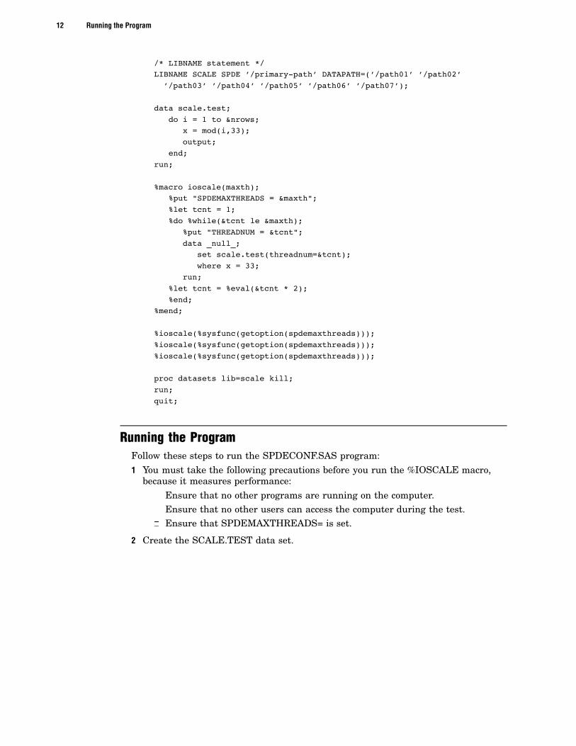
/* LIBNAME statement */LIBNAME SCALE SPDE ’/primary-path’ DATAPATH=(’/path01’ ’/path02’’/path03’ ’/path04’ ’/path05’ ’/path06’ ’/path07’);
data scale.test;do i = 1 to &nrows;
x = mod(i,33);output;
end;run;
%macro ioscale(maxth);%put "SPDEMAXTHREADS = &maxth";%let tcnt = 1;%do %while(&tcnt le &maxth);
%put "THREADNUM = &tcnt";data _null_;
set scale.test(threadnum=&tcnt);where x = 33;
run;%let tcnt = %eval(&tcnt * 2);%end;
%mend;
%ioscale(%sysfunc(getoption(spdemaxthreads)));%ioscale(%sysfunc(getoption(spdemaxthreads)));%ioscale(%sysfunc(getoption(spdemaxthreads)));
proc datasets lib=scale kill;run;quit;
Running the ProgramFollow these steps to run the SPDECONF.SAS program:1 You must take the following precautions before you run the %IOSCALE macro,
because it measures performance:� Ensure that no other programs are running on the computer.� Ensure that no other users can access the computer during the test.� Ensure that SPDEMAXTHREADS= is set.
2 Create the SCALE.TEST data set.

� Interpreting the Results 13
3 Run the %IOSCALE macro three times, noting the time for each run.4 To complete your results, use the following code to create the same data set with
the Base SAS engine:
data testbase.test;do i = 1 to &nrows;
x = mod(i,33);output;
end;run;
Run the following DATA step against the TESTBASE.TEST data set:
data _null_;set scale.test;where x=33;
run;
As in step 3, write down the real time that it took to run the DATA _NULL_.
Interpreting the ResultsFirst, average the results from the three %IOSCALE macros. (You will find the data
you need in the log file for the program, SPDECONF.LOG). If the computer is correctlyconfigured, you should see these results:
� The real time for each successive DATA step should ideally follow the curve 1/THREADNUM. That is, it should take half as much time to process with eachsuccessive doubling of the number of threads.
At the very least, for the first several iterations, the time for each successiveDATA step should decline and then after some point the curve should begin toflatten or bottom out.
� The time with one thread should be less than or equal to the time to process theDATA step with the Base SAS engine.
If the results do not fit the criteria above, something is wrong with the configurationand must be corrected.
Once you get a curve with the characteristics listed above, set the value of theinvocation option SPDEMAXTHREADS= in the SAS configuration file to the value ofTHREADNUM= where the curve flattens/bottoms (see the graph below). This willgenerally be the most efficient configuration for WHERE-clause processing but mightnot be best for other kinds of processing. In any case, if you need to specify fewerthreads for any individual SAS job, you can use THREADNUM= to overrideSPDEMAXTHREADS= temporarily. See “THREADNUM= Data Set Option” on page 64and “SPDEMAXTHREADS= System Option” on page 76 for details about these options.
The following graph summarizes the results from an actual use of theSPDECONF.SAS program. The data set has 2 numeric variables and 1 billionobservations. The WHERE expression asks for a record that is not in the data set.Without any indexes, the SPD Engine is forced to do a full scan of the data file. Notethat the number of threads is a surrogate for the number of CPUs. The scalabilitylevels off with eight threads, which is the number of CPUs on the test computer.Specifying a number of threads larger than 2 or 3 times the number of available CPUsdoes not improve performance.

14 Interpreting the Results�
Figure A1.10 Time to Read 1 Billion Rows
Min
ute
s
9.0Time to read 1 billion rows
8.0
7.0
6.0
5.0
4.0
3.0
2.0
1.0
0.0
1 2 4 8 16 32
SPDEPERFECT
Threads
64
Note:
� This type of scalability might not be seen when all the data file systems reside onthe same RAID 5 array, consisting of only three or five disks, in which case thecurve will be more or less flat all the way through. You might want to try alteringyour hardware set-up. A much better set-up would be to place each data file systemon its own RAID 5 array. Then rerun this test to see if there are improvements.
� Not only the scalability but also the overall throughput in megabytes per second isa figure that should be calculated in order to know whether the set-up isappropriate. To calculate this number, just take the size of the data set, inmegabytes, and divide it by the real time the step took in seconds. This numbershould come as close as 70 to 80 percent to the theoretical maximum of your I/O-bandwidth, if the set-up is correct.
� Make sure you assign data paths that use separate I/O controllers and that youuse hardware striping.
� On some systems, DATAPATHs are not needed if the LIBNAME domain’s primarydirectory is on a file system with hardware striping across multiple controllers.
� Check your SPDEMAXTHREADS system option. If the THREADNUM valueexceeds the SPDEMAXTHREADS setting, then SPDEMAXTHREADS will takeprecedence. You need to temporarily change SPDEMAXTHREADS to theartificially high value for this test and then restore it after the test is complete.Remember that the Base SAS software needs to be restarted in order to pick upthe change to SPDEMAXTHREADS.
�


![Fokker–Planck Equations for SPDE with Non-trace-class Noise · Fokker–Planck Equations for SPDE with Non-trace-class Noise 283 in [4, 8], but we do not allow dependence on (x,t)](https://img.dokumen.tips/doc/110x75/5f8d1f35f4b8710d1576862f/fokkeraplanck-equations-for-spde-with-non-trace-class-noise-fokkeraplanck-equations.jpg)