Embed Size (px)
Citation preview

8/10/2019 Spartan3E Tutorial 3
http://slidepdf.com/reader/full/spartan3e-tutorial-3 1/162
This is the author’s version of a work that was submitted/accepted for pub-
lication in the following source:
Banks, Jasmine (2013) The Spartan-3E tutorial 3 : using the LCD display
[version 1.0]. Queensland Univeristy of Technology. (Unpublished)
This file was downloaded from:
c Copyright 2012 Queensland University of Technology
Notice: Changes introduced as a result of publishing processes such as
copy-editing and formatting may not be reflected in this document. For a
definitive version of this work, please refer to the published source:

8/10/2019 Spartan3E Tutorial 3
http://slidepdf.com/reader/full/spartan3e-tutorial-3 2/162
Tutorial 3: Using the LCD Display 1
Xilinx Spartan-3E Project Navigator Version 14.3
The Spartan-3E
Tutorial 3:
Using the LCD DisplayVersion 1.0
Author: Jasmine Banks
© 2013, Queensland University of Technology
8/10/2019 Spartan3E Tutorial 3
http://slidepdf.com/reader/full/spartan3e-tutorial-3 3/162
Tutorial 3: Using the LCD Display 2
Xilinx Spartan-3E Project Navigator Version 14.3

8/10/2019 Spartan3E Tutorial 3
http://slidepdf.com/reader/full/spartan3e-tutorial-3 4/162
Tutorial 3: Using the LCD Display 3
Xilinx Spartan-3E Project Navigator Version 14.3
Acknowledgements
Parts of this tutorial are based on an earlier version written for Project Navigator version 9.2, written
by Matthew Dagg, Stephan Trauden and Matthew Watson, as part of ENB345 – Advanced Design in
2010.

8/10/2019 Spartan3E Tutorial 3
http://slidepdf.com/reader/full/spartan3e-tutorial-3 5/162
Tutorial 3: Using the LCD Display 4
Xilinx Spartan-3E Project Navigator Version 14.3
8/10/2019 Spartan3E Tutorial 3
http://slidepdf.com/reader/full/spartan3e-tutorial-3 6/162
Tutorial 3: Using the LCD Display 5
Xilinx Spartan-3E Project Navigator Version 14.3
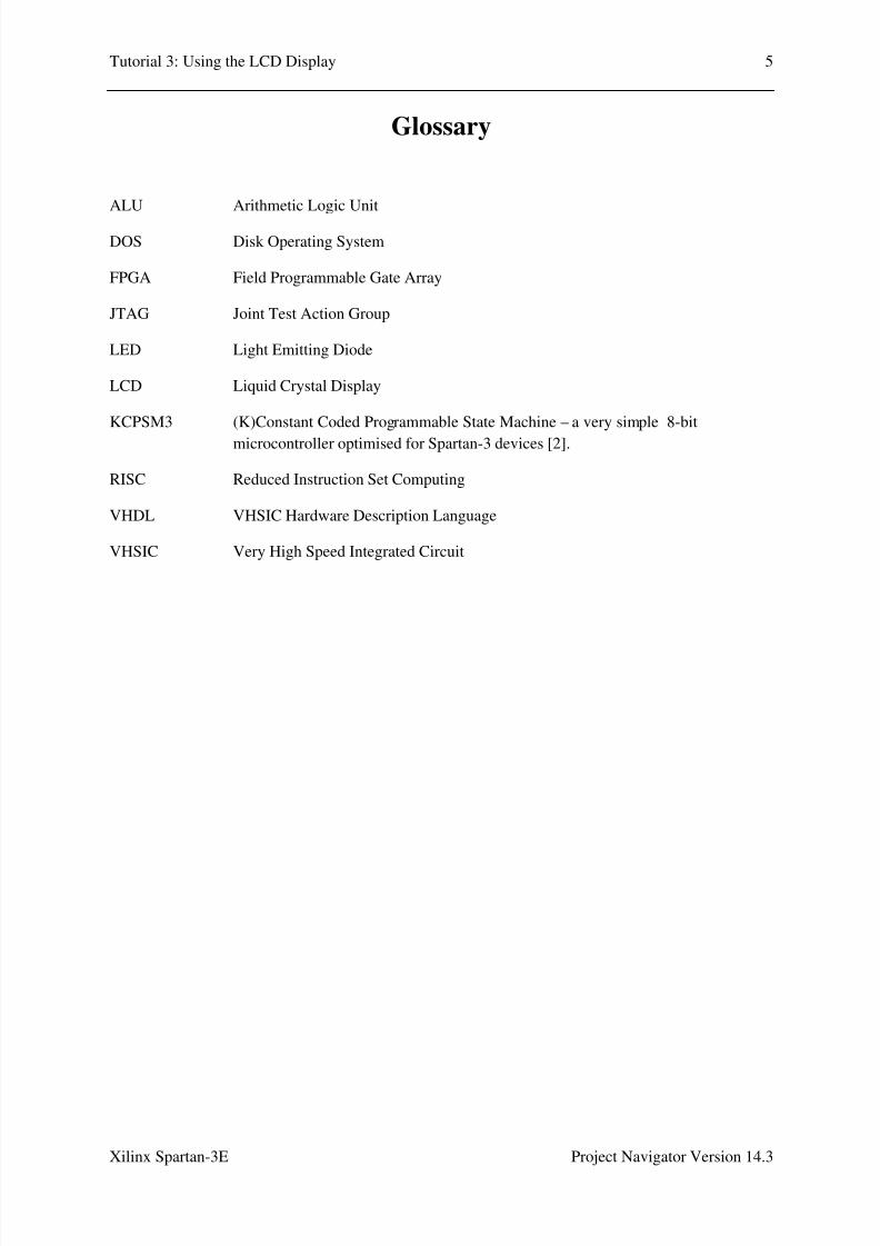
Glossary
ALU
DOS
FPGA
JTAG
LED
LCD
KCPSM3
RISC
VHDL
VHSIC
Arithmetic Logic Unit
Disk Operating System
Field Programmable Gate Array
Joint Test Action Group
Light Emitting Diode
Liquid Crystal Display
(K)Constant Coded Programmable State Machine – a very simple 8-bit
microcontroller optimised for Spartan-3 devices [2].
Reduced Instruction Set Computing
VHSIC Hardware Description Language
Very High Speed Integrated Circuit

8/10/2019 Spartan3E Tutorial 3
http://slidepdf.com/reader/full/spartan3e-tutorial-3 7/162
Tutorial 3: Using the LCD Display 6
Xilinx Spartan-3E Project Navigator Version 14.3

8/10/2019 Spartan3E Tutorial 3
http://slidepdf.com/reader/full/spartan3e-tutorial-3 8/162
Tutorial 3: Using the LCD Display 7
Xilinx Spartan-3E Project Navigator Version 14.3
Table of Contents
Acknowledgements ……………………………………………………….......………………
Glossary ……………………………………………………………………….......………….
List of Figures ……………………………………………………………....…….………….
List of Tables …………………………………………………………………………………
1.0 Introduction ………………………………………………………………....……....……
1.1 Relevant Documentation ..…………………………….……………………..……….
1.2 Pre-requisite Knowledge ……………………………………………………………..
1.3 Scope and Further help…..………………………………………………….......….....
2.0 Equipment …………………………………………………………………..................….
3.0 The PicoBlaze Microcontroller …………………………….....…...……………………...
3.1 PicoBlaze Overview……………………………………………………………………
3.2 VHDL Components and Design Process………………………………………………
3.3 PicoBlaze Interface Signals ………………………………………….....…….…………
3.4 The PicoBlaze Instruction Set…………………………………………………………
4.0 The LCD Display……………………………………......…………………........…………
4.1 The LCD Display Overview……………………………………………...……....……
4.2 LCD Memory Map.…..……………………………………………………....…....….
4.3 LCD Controller Command Set……………………………………………..…............
4.4 PicoBlaze Code for LCD Control………….……………………....……....………….
5.0 Procedure – File Setup…………………………………………………………………….
5.1 PicoBlaze Download…………………………………………………………………..
5.2 Copy Files……………….………………………………………….....………………
5.3 Setup hello.psm………………………………………………………….......………...
6.0 Procedure Part A – Hello World on the Spartan3E LCD……………………………….…
6.1 PicoBlaze Code for Hello World………………………….......……………….............6.2 Running the Assembler…………………………………………...……………………
6.3 Starting Project Navigator…….………………………………….....…………………
6.4 Creating a New Project………………………………........………..……....…………
6.5 Adding Source Files………..………………………………………..………...………
6.6 hello.vhd and kcpsm3.vhd – Observations…………………..………..………………
6.7 Adding a top_level Entity……………………………………………………………..
6.8 Editing the top_level Entity……………………………………………………………
page
3
5
9
13
15
15
15
15
17
19
19
20
22
23
25
25
26
28
31
39
39
39
40
41
4142
49
50
54
57
59
64
8/10/2019 Spartan3E Tutorial 3
http://slidepdf.com/reader/full/spartan3e-tutorial-3 9/162
Tutorial 3: Using the LCD Display 8
Xilinx Spartan-3E Project Navigator Version 14.3
6.9 top_level.vhd – Code …………….……………………….......……………….............
6.10 Syntax Checking ………………………………………………...……………………
6.11 Pin Assignment ………………………………………………….....…………………
6.12 Synthesize, Translate, Map and Place & Route ……........………..……....…………
6.13 Download Design to Board ………………………………………..………...………
6.14 Running the Program on the Spartan-3E Board ……………………..………………
7.0 Procedure Part B – Creating Custom Characters……………………………………………
7.1 Edit the .psm file………………………………………………………..………………
7.2 Running the Assembler………………………………………………………………….
7.3 Project Navigator…………………………………………………………………………
7.4 Running the Program on the Spartan-3E Board ……………………..………………..
8.0 Procedure Part C – Flashing and Shifting………………………………………………….
8.1 Edit the .psm file………………………………………………………..………………
8.2 Running the Assembler………………………………………………………………….
8.3 Project Navigator…………………………………………………………………………
8.4 Running the Program on the Spartan-3E Board ……………………..………………..
9.0 Further Information ………………………………………………………......……………
10.0 References ………..……………………………………………………...……....………
Appendix A………………...……………………………………………………......…………
A.1 hello.psm…………..………………………………………………………………….
A.2 top_level.vhd….………………………………………………………………………
Appendix B – hello.psm …………………………..……………………………......…………
Appendix C………………...……………………………………………………......…………
C.1 hello.psm…………..………………………………………………………………….
C.2 top_level.vhd….………………………………………………………………………
70
77
78
85
87
100
101
101
105
105
106
107
107
111
111
115
117
119
121
121
130
135
145
145
156

8/10/2019 Spartan3E Tutorial 3
http://slidepdf.com/reader/full/spartan3e-tutorial-3 10/162
Tutorial 3: Using the LCD Display 9
Xilinx Spartan-3E Project Navigator Version 14.3
List of Figures
Figure 2.1: Spartan-3E Development Board …………………………………….....................
Figure 3.1: PicoBlaze microncontroller block diagram.………………………………………
Figure 3.2: PicoBlaze VHDL components ..………………………………...........……….......
Figure 3.3: KCPSM3 component declaration ………………………………….…………......
Figure 3.4: Block Memory component declaration ……………….……………......................
Figure 4.1: Character LCD interface……..……………...……….............................................
Figure 4.2: DD RAM Hexadecimal addresses.…. ……………….............................................
Figure 4.3: LCD Character set…………..……………...………..……………………............
Figure 4.4: PicoBlaze Assembler code for LCD control…………………………...…….........
Figure 5.1: KCPSM3 files after unzipping……………………………………………………
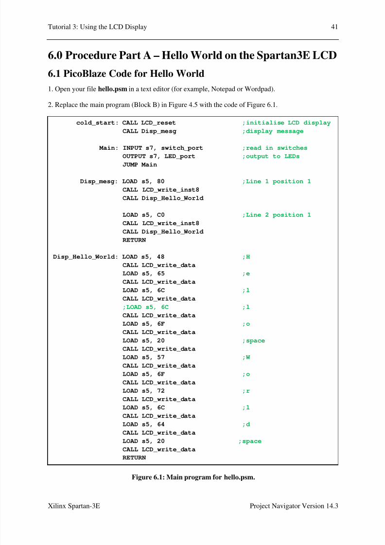
Figure 6.1: Main program for hello.psm………………………………………….……...........
Figure 6.2: KCPSM3 assembler files …………………………………..………......................
Figure 6.3: DOS Command Prompt window…………………………………….……...........
Figure 6.4: DOS Command Prompt window, with KCPSM3 command typed in ……...........
Figure 6.5: DOS Command Prompt window, after KCPSM3 successfully run ………….......
Figure 6.6: Error message which appears if KCPSM3 is run on a 64-bit machine …...............
Figure 6.7: DOSBox window …................................................................................................
Figure 6.8: DOSBox window, with KCPSM3 command typed in …..…................................
Figure 6.9: DOSBox window, after KCPSM3 successfully run …………….........................
Figure 6.10: Files in the working directory after KCPSM3 successfully run …………….......
Figure 6.11: Project Navigator Software Startup Window ……................................................
Figure 6.12: New Project Wizard, Create New Project Page ………….…….........................
Figure 6.13: New Project Wizard, Project Settings Page …………………………................
Figure 6.14: New Project Wizard, Project Summary Page ………………………..…….........
page
17
20
20
21
21
25
26
27
32
39
41
42
43
43
44
44
45
46
47
48
49
50
52
53
8/10/2019 Spartan3E Tutorial 3
http://slidepdf.com/reader/full/spartan3e-tutorial-3 11/162
Tutorial 3: Using the LCD Display 10
Xilinx Spartan-3E Project Navigator Version 14.3
Figure 6.15: Adding a source file to the project ………..…......................................................
Figure 6.16: Add Source file selection window .........................................................................
Figure 6.17: Adding Source Files window …………................................................................
Figure 6.18: kcpsm3 and hello in the Sources window ………...…..........................................
Figure 6.19: Source code for hello.vhd displayed in a tab ………….........................................
Figure 6.20: hello entity .....…...................................................................................................
Figure 6.21: kcpsm3 entity .……………………………………………....................…......….
Figure 6.22: Adding a source file to the project …………………………………..……......…
Figure 6.23: New Source Wizard, Select Source Type .............................................................
Figure 6.24: New Source Wizard, Define Module ……………………………………….……
Figure 6.25: New Source Wizard, Summary …….……...….……............................................
Figure 6.26: top_level in the Sources window ………………………………..………………
Figure 6.27: top_level.vhd, as displayed in Project Navigator, before editing ……………….
Figure 6.28: entity and architecture for top_level.vhd…………………………………………
Figure 6.29: top_level in the Sources window ………………………………………………..
Figure 6.30: top_level entity……………………………………………………………………
Figure 6.31: Component declarations ........................................................................................
Figure 6.32: Signal declarations ................................................................................................
Figure 6.33: LCD control………………………………………………………………………
Figure 6.34: Component instantiations …………………………………………………..……
Figure 6.35: Input ports ..............................................................................................................
Figure 6.36: Output ports ...........................................................................................................
Figure 6.37: Portion of Project Navigator screen with Synthesize – XST expanded ……..…..
Figure 6.38: A green tick next to Check Syntax shows that no errors were found ……….......
Figure 6.39: Portion of Project Navigator screen, with User Constraints expanded ………….
Figure 6.40: Dialog Box asking if you wish to create an Implementation Constraint File……
54
55
55
56
57
57
58
59
60
61
62
63
64
65
69
70
71
72
73
74
75
76
77
78
80
80

8/10/2019 Spartan3E Tutorial 3
http://slidepdf.com/reader/full/spartan3e-tutorial-3 12/162
Tutorial 3: Using the LCD Display 11
Xilinx Spartan-3E Project Navigator Version 14.3
Figure 6.41: Initial appearance of PlanAhead window ……………………………………….
Figure 6.42: I/O Ports displayed in a separate window ……………………………………….
Figure 6.43: I/O Ports window with individual ports expanded ……..................................….
Figure 6.44: I/O Ports window with values filled in ………………………………………….
Figure 6.45: Portion of Project Navigator screen, with Implement Design expanded ………..
Figure 6.46: Portion of Project Navigator screen, after Translate, Map and
Place & Route have successfully been run ………………………….……..
Figure 6.47: Portion of Project Navigator screen, with Implement Design expanded …..……
Figure 6.48: Portion of Project Navigator screen, after Generate Programming File
has successfully been run …………………………………………….…….
Figure 6.49: The initial iMPACT window ………………………………………………..…..
Figure 6.50: iMPACT window, after double-clicking on Boundary Scan …………………….
Figure 6.51: iMPACT window, showing Initialize Chain selected ……………………………
Figure 6.52: iMPACT window, assign configuration files ………………………………..…..
Figure 6.53: iMPACT window, assigning the configuration file for the xc3e500e ……….…..
Figure 6.54: iMPACT window, dialog box asking if we wish to attach an SPI or BPI PROM .
Figure 6.55: : iMPACT window, bypassing the xcf04s ………………………….……………
Figure 6.56: iMPACT window, bypassing the xc2c64a …………………………….………..
Figure 6.57: iMPACT window, Device Programming Properties dialog box ...........................
Figure 6.58: iMPACT window, showing the device chain …………………………..………..
Figure 6.59: iMPACT window, options which appear when right clicking on the xc3s500e ..
Figure 6.60: iMPACT window, after the program has been successfully downloadedto the Spartan-3E board …………………………………………..………
Figure 6.61: The Spartan-3E board with the program running for Part A……..........…...……..
Figure 7.1: Main program loop for Part B………………………………………………………..
Figure 7.2: Disp_mesg subroutine for Part B………………………………………………….
Figure 7.3: Disp_cust_chars subroutine for Part B…………………………………………….
Figure 7.4: Setup_cust_chars subroutine for Part B………...…………………………………
81
81
82
84
85
86
87
88
89
90
91
92
93
94
95
96
97
98
98
99
100
101
101
102
103
8/10/2019 Spartan3E Tutorial 3
http://slidepdf.com/reader/full/spartan3e-tutorial-3 13/162
Tutorial 3: Using the LCD Display 12
Xilinx Spartan-3E Project Navigator Version 14.3
Figure 7.5: Locate Missing Source Files window………………………………………..........
Figure 7.6: The Spartan-3E board with the program running for Part B………………………
Figure 8.1: Delay constants for shifting………………………………………………………..
Figure 8.2: Main program loop for Part C………………………………………………………
Figure 8.3: Disp_mesg subroutine for Part C………………………………………………….
Figure 8.4: Interrupt service routine and ADDRESS directive…………………………………
Figure 8.5: Library declarations to add………………………………………………………..
Figure 8.6: Signals used for interrupts…………………………………………………………
Figure 8.7: Processes associated with interrupt control………………………………………..
Figure 8.8: The Spartan-3E board with the program running for Part C………………………
105
106
107
108
109
110
111
112
113
115

8/10/2019 Spartan3E Tutorial 3
http://slidepdf.com/reader/full/spartan3e-tutorial-3 14/162

8/10/2019 Spartan3E Tutorial 3
http://slidepdf.com/reader/full/spartan3e-tutorial-3 15/162
Tutorial 3: Using the LCD Display 14
Xilinx Spartan-3E Project Navigator Version 14.3

8/10/2019 Spartan3E Tutorial 3
http://slidepdf.com/reader/full/spartan3e-tutorial-3 16/162
Tutorial 3: Using the LCD Display 15
Xilinx Spartan-3E Project Navigator Version 14.3
1.0 Introduction
This tutorial is designed to assist users who wish to use the LCD screen on the Spartan-3E board. In
this tutorial, the PicoBlaze microcontroller is used to control the LCD.
The tutorial is organised into three Parts. In Part A, code is written to display the message “Hello
World” on the LCD. Part B demonstrates how to define and display custom characters. Finally, Part
C shows how the display can be shifted and flashed. Shifting is done by using a delay in the main
PicoBlaze program loop, while flashing is done using the PicoBlaze interrupt. The slider switches can
be used to select the shifting direction, and to turn shifting and flashing on and off.
Each part of the tutorial steps through the following:
• Writing a PicoBlaze assembly language (.psm) file, and assembling the .psm file using
KCPSM3.
•
Writing a top level VHDL module to connect the PicoBlaze microcontroller (KCPSM3component) and the program ROM, connect the required input and output ports, and
implement any extra functionality that is required.
• Connecting the top level module inputs and outputs to the components on the Spartan-3E
board.
• Downloading the program to the Spartan-3E board using the Project Navigator software.
1.1 Relevant Documentation
Before commencing this tutorial, it would be helpful to download the Spartan-3E FPGA Starter Kit
Board User Guide [1], and the PicoBlaze 8-bit Embedded Microcontroller User Guide [2].
1.2 Pre-requisite Knowledge
Although this tutorial can be worked through on its own, it would be helpful if the user has already
worked through “The Spartan-3E Tutorial 1: Introduction to FGPA Programming” [3], and “The
Spartan-3E Tutorial 2: Introduction to Using the PicoBlaze Microcontroller” [4].
1.3 Scope and Further help
This tutorial is designed to help users who wish to use the LCD screen on the Spartan-3E FPGA
board. For the purposes of understanding this tutorial, some background information is provided on
the PicoBlaze, and the Spartan-3E LCD interface. Segments of KCPSM3 and VHDL code are also
presented. However, this tutorial is not designed to be an exhaustive reference on the Spartan3E
LCD, the PicoBlaze or VHDL. More detailed information on the Spartan3E and the PicoBlaze can be
found in the documentation of [1,2,9]. For help with VHDL, the user can consult with a number of
textbooks on the subject, such as [5,6], or find help online. The book by Chu [7] is also a useful
reference for the Spartan-3 with many useful examples. Reference designs for the Spartan-3E can
also be found here [8].

8/10/2019 Spartan3E Tutorial 3
http://slidepdf.com/reader/full/spartan3e-tutorial-3 17/162
Tutorial 3: Using the LCD Display 16
Xilinx Spartan-3E Project Navigator Version 14.3

8/10/2019 Spartan3E Tutorial 3
http://slidepdf.com/reader/full/spartan3e-tutorial-3 18/162
Tutorial 3: Using the LCD Display 17
Xilinx Spartan-3E Project Navigator Version 14.3
2.0 Equipment
The following are required to work through this tutorial:
• The Xilinx ISE Project Navigator software. Version 14.3 was used in this tutorial, but older
versions of the software can be used. The software can be downloaded with a free WebPacklicense from the Xilinx website, http://www.xilinx.com/ . The user will need to register and
log in.
• The Spartan-3E Starter Kit, including the Spartan-3E development board, power cable and
USB cable for PC connection. The Spartan-3E development board is shown in Figure 2.1.
• The Picoblaze 8-bit Microcontroller software. The software can be downloaded for free from
the Xilinx website, http://www.xilinx.com/ . Again the user will need to register and log in.
• If a 64-bit machine is being used, software which can run 32-bit DOS programs, such as
DOSBox, will be needed to run the KCPSM3 executable. DOSBox can be downloaded fromhttp://www.dosbox.com/ .
Figure 2.1: Spartan-3E Development Board.
Reset
Button
ON/OFF
FPGA
JTAG
LEDs
SW0-3
PushButtons
LCD
USB
Power

8/10/2019 Spartan3E Tutorial 3
http://slidepdf.com/reader/full/spartan3e-tutorial-3 19/162
Tutorial 3: Using the LCD Display 18
Xilinx Spartan-3E Project Navigator Version 14.3

8/10/2019 Spartan3E Tutorial 3
http://slidepdf.com/reader/full/spartan3e-tutorial-3 20/162
Tutorial 3: Using the LCD Display 19
Xilinx Spartan-3E Project Navigator Version 14.3
3.0 The PicoBlaze Micocontroller
The PicoBlaze is an 8-bit RISC microcontroller which is specifically designed and optimized for the
Spartan-3 family. One of its main advantages is its small size, requiring only 96 FPGA slices. It is
provided as a free, source-level VHDL file with royalty-free re-use within Xilinx FPGAs [2].
3.1 PicoBlaze Overview
A block diagram of the PicoBlaze microcontroller is shown in Figure 3.1. Some of the main features
are described as follows:
Instruction PROM Stores up to 1024 instructions consisting of the program to be run by the
microcontroller.
Program Counter Points to the next instruction to be executed.
CALL/RETURN Stack The stack can contain up to 31 addresses for use in subroutine CALL and
RETURN instructions. This means that up to 31 subroutine calls can be
made before the stack overwrites itself, replacing the oldest value first.
Scratchpad RAM 64 bytes of internal memory that can be accessed using STORE and
FETCH instructions.
Registers 16 byte-wide general purpose registers.
ALU Used to calculate operations such as add, subtract, AND, OR, XOR and
shift and rotate functions.
Ports The PicoBlaze microcontroller supports up to 256 input and 256 output
ports for connecting to peripheral devices or for use by other logic within
the FPGA.
Flags The ZERO and CARRY flags are set or cleared depending on the results
of ALU operations.
Interrupts An optional INTERRUPT input allows the PicoBlaze to handle
asynchronous external events. The INTERRUPT_ENABLE flag can be
set to enable the INTERRUPT input port.

8/10/2019 Spartan3E Tutorial 3
http://slidepdf.com/reader/full/spartan3e-tutorial-3 21/162
Tutorial 3: Using the LCD Display 20
Xilinx Spartan-3E Project Navigator Version 14.3
Figure 3.1: PicoBlaze microcontroller block diagram [2].
3.2 VHDL Components and Design Process
Figure 3.2 shows that the PicoBlaze consists of two VHDL components. The KCPSM3 component
provides the ALU, registers, scratchpad RAM etc. The Block Memory (Program) component
corresponds to the Instruction PROM in Figure 3.1 and contains the instructions to be executed.
Figure 3.2: PicoBlaze VHDL components [9].
The basic design process using the PicoBlaze follows the steps below:
1. A PicoBlaze program is written in assembly language. This file is given the extension .psm.

8/10/2019 Spartan3E Tutorial 3
http://slidepdf.com/reader/full/spartan3e-tutorial-3 22/162
Tutorial 3: Using the LCD Display 21
Xilinx Spartan-3E Project Navigator Version 14.3
2. The KCPSM3 assembler is run on the .psm file, and a VHDL file (extension .vhd) which embeds
the instructions in the Block Memory component, is output. The name of the .vhd file will be derived
from the name of the .psm file, i.e., if the .psm file is myprog.psm, then the .vhd file will be
myprog.vhd.
3. The VHDL code for the Block Memory and KCPSM3 modules is loaded into Project Navigator.Further VHDL code will need to be written to connect the two modules and interface to the outside
world.
4. The project is compiled using the Project Navigator Software, and ultimately downloaded to the
Spartan-3E board (or other target hardware).
Figures 3.3 and 3.4 show the VHDL component declarations for the KCPSM3 and Block Memory
respectively. Note that the name of the Block Memory component is derived from the name of the
original .psm file, i.e., if the .psm file was myprog.psm, the Block Memory component will be called
myprog.
Figure 3.3: KCPSM3 component declaration.
Figure 3.4: Block Memory component declaration.
component myprog
port (address : in std_logic_vector(9 downto 0);
instruction : out std_logic_vector(17 downto 0);
clk : in std_logic);
end component;
component kcpsm3
port (address : out std_logic_vector(9 downto 0);
instruction : in std_logic_vector(17 downto 0);
port_id : out std_logic_vector(7 downto 0);
write_strobe : out std_logic;
out_port : out std_logic_vector(7 downto 0);
read_strobe : out std_logic;
in_port : in std_logic_vector(7 downto 0);
interrupt : in std_logic;interrupt_ack : out std_logic;
reset : in std_logic;
clk : in std_logic);
end component;
N!e o" #o!$onent %er&'e%
"ro! n!e o" ($s! "&)e

8/10/2019 Spartan3E Tutorial 3
http://slidepdf.com/reader/full/spartan3e-tutorial-3 23/162
Tutorial 3: Using the LCD Display 22
Xilinx Spartan-3E Project Navigator Version 14.3
In addition, it is possible to download a new program into the Block Memory, using the JTAG port on
the Spartan-3E board. This can provide a convenient means to update the program without having to
recompile the VHDL code in Project Navigator. This is not covered by this tutorial, and the user can
refer to documentation such as [2] for more information.
3.3 PicoBlaze Interface Signals
The Interface signals to the PicoBlaze are summarised in Table 3.1.
Signal Direction Description
IN_PORT[7:0] Input Input data is presented on this port during an INPUT instruction.
The data is captured on the rising edge of CLK.
INTERRUPT Input If the INTERRUPT_ENABLE flag is set by the application code,generate an INTERRUPT Event. If the INTERRUPT_ENABLE
flag is cleared, this input is ignored.
RESET Input Assert this input High for at least one CLK cycle, to reset the
PicoBlaze microcontroller. A Reset Event is automatically
generated immediately following FPGA configuration.
CLK Input Clock Input.
OUT_PORT[7:0] Output Output data appears on this port during an OUTPUT instruction.
Output data is captured on the rising CLK edge when
WRITE_STROBE is High.
PORT_ID[7:0] Output The I/O port address appears on this port for two CLK cycles
during an INPUT or OUTPUT instruction.
READ_STROBE Output When asserted High, this signal indicates that input data on the
IN_PORT[7:0] port was captured to the specified data register
during an INPUT instruction.
WRITE_STROBE Output When asserted High, this signal validates the output data on the
OUT_PORT[7:0] port during an OUTPUT instruction.
INTERRUPT_ACK Output When asserted High, this signal acknowledges that an
INTERRUPT Event occurred.
Table 3.1: PicoBlaze interface Signals [2].

8/10/2019 Spartan3E Tutorial 3
http://slidepdf.com/reader/full/spartan3e-tutorial-3 24/162
Tutorial 3: Using the LCD Display 23
Xilinx Spartan-3E Project Navigator Version 14.3
3.3 The PicoBlaze Instruction Set
The PicoBlaze Instruction Set is summarised in Table 3.2(a) and (b).
Instruction Description
ADD sX, kk Add register sX with literal kk.
ADD sX, sY Add register sX with register sY.
ADDCY sX, kk Add register sX with literal kk with CARRY bit.
ADDCY sX, sY Add register sX with register sY with CARRY bit.
AND sX, kk Bitwise AND register sX with literal kk.
AND sX, sY Bitwise AND register sX with register sY.
CALL aaa Unconditionally call subroutine at aaa.
CALL C, aaa If CARRY flag set, call subroutine at aaa.
CALL NC, aaa If CARRY flag not set, call subroutine at aaa.
CALL NZ, aaa If ZERO flag not set, call subroutine at aaa.
CALL Z, aaa If ZERO flag set, call subroutine at aaa.
COMPARE sX, kk Compare register sX with literal kk Set CARRY and ZERO flags as
appropriate. Registers are unaffected.
COMPARE sX, sY Compare register sX with register sY. Set CARRY and ZERO flags as
appropriate. Registers are unaffected.
DISABLE INTERRUPT Disable interrupts.
ENABLE INTERRUPT Enable interrupts.
FETCH sX, sY Read scratchpad RAM location pointed to by register sY into register sX.
FETCH sX, ss Read scratchpad RAM location ss into register sX.
INPUT sX, sY Read value on input port pointed to by register sY into register sX.
INPUT sX, pp Read value on input port pp into register sX.
JUMP aaa Unconditionally jump to aaa.
JUMP C, aaa If CARRY flag set, jump to aa.
JUMP NC, aaa If CARRY flag not set, jump to aa.
JUMP NZ, aaa If ZERO flag not set, jump to aa.
JUMP Z, aaa If ZERO flag set, jump to aa.
LOAD sX, kk Load register sX with literal kk.
LOAD sX, sY Load register sX with register sY.
OR sX, kk Bitwise OR register sX with literal kk.
Table 3.2(a): PicoBlaze instruction set [2].

8/10/2019 Spartan3E Tutorial 3
http://slidepdf.com/reader/full/spartan3e-tutorial-3 25/162
Tutorial 3: Using the LCD Display 24
Xilinx Spartan-3E Project Navigator Version 14.3
Instruction Description
OR sX, sY Bitwise OR register sX with register sY.
OUTPUT sX, sY Write register sX to output port location pointed to by register sY.
OUTPUT sX, pp Write register sX to output port location pp.
RETURN Return unconditionally from subroutine.
RETURN C If CARRY flag set, return from subroutine.
RETURN NC If CARRY flag not set, return from subroutine.
RETURN NZ If ZERO flag not set, return from subroutine.
RETURN Z If ZERO flag set, return from subroutine.
RETURNI DISABLE Return from interrupt service routine. Interrupt remains disabled.
RETURNI ENABLE Return from interrupt service routine. Re-enable interrupt.
RL sX Rotate sX register left.
RR sX Rotate sX register right.
SL0 sX Shift register sX left, zero fill.
SL1 sX Shift register sX left, one fill.
SLA sX Shift register sX left through all bits, including CARRY.
SLX sX Shift register sX left. Bit sX[0] is unaffected.
SR0 sX Shift register sX right, zero fill.
SR1 sX Shift register sX right, one fill.
SRA sX Shift register sX right through all bits, including CARRY.
SRX sX Shift register sX right. Bit sX[7] is unaffected.
STORE sX, sY Write register sX to scratchpad RAM location pointed to by register sY.
STORE sX, ss Write register sX to scratchpad RAM location ss.
SUB sX, kk Subtract literal kk from literal sX.
SUB sX, sY Subtract register sY from register sX.
SUBCY sX, kk Subtract literal kk from literal sX with CARRY (borrow).
SUBCY sX, sY Subtract register sY from register sX with CARRY (borrow).TEST sX, kk Test bits in register sX against literal kk. Update CARRY and ZERO
flags. Registers are unaffected.
TEST sX, sY Test bits in register sX against register sY. Update CARRY and ZERO
flags. Registers are unaffected.
XOR sX, kk Bitwise XOR register sX with literal kk.
XOR sX, sY Bitwise XOR register sX with register sY.
Table 3.2(b): PicoBlaze instruction set [2].

8/10/2019 Spartan3E Tutorial 3
http://slidepdf.com/reader/full/spartan3e-tutorial-3 26/162
Tutorial 3: Using the LCD Display 25
Xilinx Spartan-3E Project Navigator Version 14.3
4.0 The LCD Display
4.1 LCD Display Overview
The Spartan-3E contains a Liquid Crystal Display (LCD) which displays 2 lines of 16 characters each.The FPGA controls the LCD through a 4-bit interface, as shown in Figure 4.1. The LCD actually
supports an 8-bit interface, however the Spartan-3E uses a 4-bit interface to remain compatible with
other Xilinx products, and to minimise pin count.
Figure 4.1: Character LCD interface [1].
The four LCD data signals are shared with the Intel Strataflash memory on the Spartan-3E. The
interaction between the LCD and the StrataFlash will depend on the design [1]. When CE0 = ‘1’, the
the StrataFlash will be disabled and the FPGA has full read/write access to the LCD.

8/10/2019 Spartan3E Tutorial 3
http://slidepdf.com/reader/full/spartan3e-tutorial-3 27/162
Tutorial 3: Using the LCD Display 26
Xilinx Spartan-3E Project Navigator Version 14.3
4.2 LCD Memory Map
The LCD Controller has three internal memory regions, which are outlined in this section. Before
accessing any of these memory regions, the display must be initialised.
4.2.1 Display Data RAM (DD RAM)
The Display Data RAM (DD RAM) stores the character codes to be displayed on the screen. There
are 80 physical locations in DD RAM, 40 per line. Only 32 characters can be displayed at a time (16
per line). Figure 4.2 shows the character display addresses for line 1 and line 2. Locations 0x00 to
0x0F in line 1 and 0x40 to 0x4F in line 2 are initially displayed. Addresses 0x10 to 0x27 and 0x50 to
0x67 can be used to store non-displayed data, or can be displayed by using the LCD’s shifting
functions.
Figure 4.2: DD RAM Hexadecimal addresses [1].
4.2.2 Character Generator ROM (CG ROM)
The Character Generator ROM (CG ROM) contains the font bitmaps for the predefined characters
that can be displayed on the LCD. The bytes stored in the DD RAM address a location in the CG
ROM. As shown in Figure 4.3, the upper nibble indexes the CG ROM column while the lower nibble
indexes the CG ROM row. The CG ROM contains ASCII characters and Japanese kana characters.
For ASCII characters, the CG ROM address corresponds to the ASCII character code.

8/10/2019 Spartan3E Tutorial 3
http://slidepdf.com/reader/full/spartan3e-tutorial-3 28/162
Tutorial 3: Using the LCD Display 27
Xilinx Spartan-3E Project Navigator Version 14.3
Figure 4.3: LCD character set [1].
4.2.3 Character Generator RAM (CG RAM)
The Character Generator RAM (CG RAM) allows eight custom characters to be created and stored.
The CG RAM occupies addresses 0x00 to 0x07 in the CG ROM. To write to the CG RAM, the Set
CG RAM Address command is first used to set the address in the CGRAM and the row in the bitmap
to be written to. Next, the Write Data to CG RAM or DD RAM command is used to write each row
of the bitmap. Details of these LCD commands are given in Section 4.3. Table 4.1 shows an
example where a checkerboard character bitmap is created in CG RAM location 0x03. The display
will be lit where there is a ‘1’ in the character bitmap, and unlit where there is a ‘0’. The bottom line
is usually left unlit to allow for a cursor.

8/10/2019 Spartan3E Tutorial 3
http://slidepdf.com/reader/full/spartan3e-tutorial-3 29/162
Tutorial 3: Using the LCD Display 28
Xilinx Spartan-3E Project Navigator Version 14.3
Upper Nibble Lower Nibble
Write Data to CG RAM of DD RAM
A5 A4 A3 A2 A1 A0 D7 D6 D5 D4 D3 D2 D1 D0
Character Address Row Address Don’t Care Character Bitmap
0 1 1 0 0 0 - - - 0 1 0 1 00 1 1 0 0 1 - - - 1 0 1 0 1
0 1 1 1 1 0 - - - 0 1 0 1 0
0 1 1 0 1 1 - - - 1 0 1 0 1
0 1 1 1 0 0 - - - 0 1 0 1 0
0 1 1 1 0 1 - - - 1 0 1 0 1
0 1 1 1 1 0 - - - 0 1 0 1 0
0 1 1 1 1 1 - - - 0 0 0 0 0
Table 4.1: Example custom character at CG RAM location 0x03 [1].
4.3 LCD Controller Command Set
The commands to control the LCD are summarised in Table 4.2. Commands are sent to the LCD in
two 4-bit nibbles, the upper nibble is sent first, followed by the lower nibble.
Function
L C D_ R S
L C D_ R W
Upper Nibble Lower Nibble
D B 7
D B 6
D B 5
D B 4
D B 3
D B 2
D B 1
D B 0
Clear Display 0 0 0 0 0 0 0 0 0 1
Return Cursor Home 0 0 0 0 0 0 0 0 1 -
Entry Mode Set 0 0 0 0 0 0 0 1 I/D S
Display On/Off 0 0 0 0 0 0 1 D C B
Cursor and Display Shift 0 0 0 0 0 1 S/C R/L - -
Function Set 0 0 0 0 1 0 1 0 - -
Set CGRAM Address 0 0 0 1 A5 A4 A3 A2 A1 A0
Set DDRAM Address 0 0 1 A6 A5 A4 A3 A2 A1 A0
Read Busy Flag and Address 0 1 BF A6 A5 A4 A3 A2 A1 A0
Write Data to CG RAM or DD RAM 1 0 D7 D6 D5 D4 D3 D2 D1 D0
Read Data from CG RAM or DD RAM 1 1 D7 D6 D5 D4 D3 D2 D1 D0
Table 4.2: LCD Character display command set [1].

8/10/2019 Spartan3E Tutorial 3
http://slidepdf.com/reader/full/spartan3e-tutorial-3 30/162
Tutorial 3: Using the LCD Display 29
Xilinx Spartan-3E Project Navigator Version 14.3
The LCD commands in Table 4.2, and the values of the bits are detailed as follows:
Disable If the LCD_E signal is low, all other inputs to the LCD
are ignored and the LCD is disabled.
Clear Display Clears the display and returns the cursor to the home
position.
Return Cursor Home Return the cursor to the home position, top left corner.
Entry Mode Set Sets the cursor move direction and specifies whether or
not to shift the display, during data reads and writes.
I/D (Increment/Decrement) bit – Sets the direction of
cursor movement or display shift.
I/D
0 Cursor or display moves to left.
1 Cursor or display moves to right.
S (Shift) bit – Turn display shift on or off.
S
0 Shifting disabled.
1 Shifting enabled, and direction of shifting given
by I/D bit. Appears as though the cursor position
remains constant and the display moves.
Display On/Off Display, cursor and cursor blinking are turned on or off.
D (Display) bit – Turns the display on or off.
I/D
0 Display off.
1 Display on.
C (Cursor) bit – Turn cursor on or off.
S
0 Cursor off.
1 Cursor on.
B (Cursor Blink) bit – Turn cursor blinking on or off.
S
0 Cursor blinking off.
1 Cursor blinking on.

8/10/2019 Spartan3E Tutorial 3
http://slidepdf.com/reader/full/spartan3e-tutorial-3 31/162
Tutorial 3: Using the LCD Display 30
Xilinx Spartan-3E Project Navigator Version 14.3
Cursor and Display Shift Moves the cursor and shifts the display. The cursor
automatically moves to the second line if it moves past
the 40th character on the first line. When the display is
shifted, both lines move at the same time.
D (Display) bit – Turns the display on or off.
S/C R/L
0 0 Shift the cursor to the left.
0 1 Shift the cursor to the right.
1 0 Shift the entire display to the left.
1 1 Shift the entire display to the right.
Function Set Sets interface data length, number of display lines, and
character font. The Spartan-3E supports a single
function set with value 0x28.
Set CG RAM Address Set the CG RAM address. All subsequent read/write
commands will be to/from CG RAM.
Set DD RAM Address Set the DD RAM address. All subsequent read/write
commands will be to/from DD RAM.
Read Busy Flag and Address Reads the busy flag (BF) to determine if an internal
operation is in progress, and reads the current address
counter. BF = 1 indicates that an internal operation is in
progress.
Write Data to CG RAM or DD RAM Write data into CG RAM if this command follows a Set
CG RAM Address command, and write data into DD
RAM if this command follows a Set DD RAM Address
command.
Read Data from CG RAM or DD RAM Read data from CG RAM if this command follows a Set
CG RAM Address command, and read data from DD
RAM if this command follows a Set DD RAM Address
command.

8/10/2019 Spartan3E Tutorial 3
http://slidepdf.com/reader/full/spartan3e-tutorial-3 32/162
Tutorial 3: Using the LCD Display 31
Xilinx Spartan-3E Project Navigator Version 14.3
4.4 PicoBlaze Code for LCD Control
In this tutorial, the PicoBlaze microcontroller is used to control the LCD display. Figure 4.5 shows a
skeleton program in KCPSM3 Assembler code, which contains a number of subroutines for LCD
control, and a placeholder main program. The LCD and delay subroutines presented here are from the
Initial Design for the Spartan-3E FPGA Starter Kit Board , control.psm file, developed by Ken
Chapman. This implements the initial design shipped with the board, and is one of the Spartan-3E
FPGA Starter Kit Board Design Examples, Xilinx reference design resources that are available for
download from [8].
In the code of Figure 4.5, comments have been printed in green, to distinguish them from assembler
instructions and directives. To assist with explanation, the code has been split into colour-coded
blocks. The purpose of each block and where applicable, each subroutine, are outlined in Table 4.2.
The blocks are colour-coded in Table 4.3 and Figure 4.5 for easier identification.
Block subroutines purpose
Block A -Definition of constants for the input/output ports for the LEDs,
switches and LCD.
Block B -
Main program – Calls LCD_reset, and then enters an infinite loop
which reads in the values of the slider switches and push buttons,
and then outputs these values to the LEDs. The main program
can be thought of as a placeholder which later in this tutorial, will
be replaced with code that calls the LCD control subroutines.
Block C
Software delay routines – Use a series of loops to delay for a
given amount of time.
delay_1us Delay for 1µs.
delay_40us Delay for 40 µs.delay_1ms Delay for 1ms.
delay_20ms Delay for 20ms.
delay_1s Delay for 1s.
Block D
LCD Character module routines
LCD_pulse_E Send an LCD_E pulse
LCD_write_inst4 Write a nibble (4 bits) to the LCD
LCD_write_inst8 Write an 8 bit instruction to the LCD. Calls LCD_write_inst4 to
send two nibbles.
LCD_write_data Write data to the display
LCD_read_data8 Read data from the display
LCD_reset Perform initialisation and clear the display.
Table 4.3: Explanation of code for Figure 4.5.

8/10/2019 Spartan3E Tutorial 3
http://slidepdf.com/reader/full/spartan3e-tutorial-3 33/162
Tutorial 3: Using the LCD Display 32
Xilinx Spartan-3E Project Navigator Version 14.3
;*******************************************************************;Port definitions
;*******************************************************************;
CONSTANT LED_port, 80 ;8 simple LEDsCONSTANT LED0, 01 ; LED 0 - bit0
CONSTANT LED1, 02 ; 1 - bit1 CONSTANT LED2, 04 ; 2 - bit2 CONSTANT LED3, 08 ; 3 - bit3 CONSTANT LED4, 10 ; 4 - bit4 CONSTANT LED5, 20 ; 5 - bit5 CONSTANT LED6, 40 ; 6 - bit6 CONSTANT LED7, 80 ; 7 - bit7;CONSTANT switch_port, 00 ;Read switches and press buttons CONSTANT switch0, 01 ; Switches SW0 - bit0 CONSTANT switch1, 02 ; SW1 - bit1
CONSTANT switch2, 04 ; SW2 - bit2 CONSTANT switch3, 08 ; SW3 - bit3
CONSTANT BTN_east, 10 ; Buttons East - bit4CONSTANT BTN_south, 20 ; South - bit5CONSTANT BTN_north, 40 ; North - bit6 CONSTANT BTN_west, 80 ; West - bit7;;;LCD interface ports;;The master enable signal is not used by the LCD display itself;but may be required to confirm that LCD communication is active.;This is required on the Spartan-3E Starter Kit if the StrataFLASH;is used because it shares the same data pins and conflicts must be;avoided.
;CONSTANT LCD_output_port, 40 ;LCD character module output
;data and controlCONSTANT LCD_E, 01 ; active High Enable E - bit0 CONSTANT LCD_RW, 02 ; Read=1 Write=0 RW - bit1 CONSTANT LCD_RS, 04 ; Instruction=0 Data=1 RS - bit2 CONSTANT LCD_drive, 08 ; Master enable (active High)
; - bit3CONSTANT LCD_DB4, 10 ; 4-bit Data DB4 - bit4 CONSTANT LCD_DB5, 20 ; interface Data DB5 - bit5 CONSTANT LCD_DB6, 40 ; Data DB6 - bit6 CONSTANT LCD_DB7, 80 ; Data DB7 - bit7;
;CONSTANT LCD_input_port, 02 ;LCD character module input data
CONSTANT LCD_read_spare0, 01 ; Spare bits - bit0 CONSTANT LCD_read_spare1, 02 ; are zero - bit1
CONSTANT LCD_read_spare2, 04 ; - bit2 CONSTANT LCD_read_spare3, 08 ; - bit3 CONSTANT LCD_read_DB4, 10 ; 4-bit Data DB4 - bit4 CONSTANT LCD_read_DB5, 20 ; interface Data DB5 - bit5CONSTANT LCD_read_DB6, 40 ; Data DB6 - bit6
CONSTANT LCD_read_DB7, 80 ; Data DB7 - bit7;;
B L O C K A
Figure 4.4(a): PicoBlaze Assembler code for LCD control.

8/10/2019 Spartan3E Tutorial 3
http://slidepdf.com/reader/full/spartan3e-tutorial-3 34/162
Tutorial 3: Using the LCD Display 33
Xilinx Spartan-3E Project Navigator Version 14.3
;Constant to define a software delay of 1us. This must be adjusted;to reflect the clock applied to KCPSM3. Every instruction executes
;in 2 clock cycles making the calculation highly predictable. The;'6' in the following equation even allows for 'CALL delay_1us'
;instruction in the initiating code.;
;delay_1us_constant = (clock_rate - 6)/4 Where 'clock_rate';is in MHz;;Example: For a 50MHz clock the constant value is (10-6)/4 = 11;(0B Hex).;For clock rates below 10MHz the value of 1 must be used and the;operation will become lower than intended.;CONSTANT delay_1us_constant, 0B;
B L O C K A
;;*******************************************;Initialise the system
;*******************************************;
cold_start: CALL LCD_reset ;initialise LCD display;
Main: INPUT s7, switch_port ;read in switches
OUTPUT s7, LED_port ;output to LEDsJUMP Main;;
B L O C K B
;;*******************************************;Software delay routines;*******************************************
;;;Delay of 1us.;
;Constant value defines reflects the clock applied;to KCPSM3. Every instruction executes in 2 clock
;cycles making the calculation highly predictable.;The '6' in the following equation even allows for;'CALL delay_1us' instruction in the initiating code.;; delay_1us_constant = (clock_rate - 6)/4; Where 'clock_rate' is in MHz;
;Registers used s0;
delay_1us: LOAD s0, delay_1us_constantwait_1us: SUB s0, 01
JUMP NZ, wait_1usRETURN
;;Delay of 40us.
;;Registers used s0, s1;
B L O C K C
Figure 4.4(b): PicoBlaze Assembler code for LCD control.

8/10/2019 Spartan3E Tutorial 3
http://slidepdf.com/reader/full/spartan3e-tutorial-3 35/162
Tutorial 3: Using the LCD Display 34
Xilinx Spartan-3E Project Navigator Version 14.3
delay_40us: LOAD s1, 28 ;40 x 1us = 40uswait_40us: CALL delay_1us
SUB s1, 01JUMP NZ, wait_40us
RETURN;
;;Delay of 1ms.;;Registers used s0, s1, s2;
delay_1ms: LOAD s2, 19 ;25 x 40us = 1ms wait_1ms: CALL delay_40us
SUB s2, 01JUMP NZ, wait_1msRETURN;
;Delay of 20ms.;
;Delay of 20ms used during initialisation.;;Registers used s0, s1, s2, s3;
delay_20ms: LOAD s3, 14 ;20 x 1ms = 20ms wait_20ms: CALL delay_1ms
SUB s3, 01JUMP NZ, wait_20msRETURN;;Delay of approximately 1 second.;;Registers used s0, s1, s2, s3, s4
;delay_1s: LOAD s4, 32 ;50 x 20ms = 1000ms
wait_1s: CALL delay_20msSUB s4, 01JUMP NZ, wait_1sRETURN;
B L O C
K C
;;;**************************************************;LCD Character Module Routines;**************************************************
;
;LCD module is a 16 character by 2 line display but;all displays are very similar The 4-wire data;interface will be used (DB4 to DB7).;;The LCD modules are relatively slow and software;delay loops are used to slow down KCPSM3;adequately for the LCD to communicate. The delay;routines are provided in a different section (see;above in this case).
;;
B L O C K D
Figure 4.4(c): PicoBlaze Assembler code for LCD control.

8/10/2019 Spartan3E Tutorial 3
http://slidepdf.com/reader/full/spartan3e-tutorial-3 36/162

8/10/2019 Spartan3E Tutorial 3
http://slidepdf.com/reader/full/spartan3e-tutorial-3 37/162
Tutorial 3: Using the LCD Display 36
Xilinx Spartan-3E Project Navigator Version 14.3
OR s4, LCD_drive ;Enable=1 CALL LCD_write_inst4 ;write upper nibble
CALL delay_1us ;wait >1us LOAD s4, s5 ;select lower nibble
;with SL1 s4 ;Enable=1
SL0 s4 ;RS=0 Instruction SL0 s4 ;RW=0 Write SL0 s4 ;E=0 CALL LCD_write_inst4 ;write lower nibble CALL delay_40us ;wait >40usLOAD s4, F0 ;Enable=0 RS=0
;Instruction, RW=0;Write, E=0
;OUTPUT s4, LCD_output_port ;Release master enable;
RETURN;
;Write 8-bit data to LCD display.;;The 8-bit data should be provided in register s5.;Data bytes are written using the following sequence; Upper nibble; wait >1us; Lower nibble; wait >40us;;Registers used s0, s1, s4, s5;
LCD_write_data: LOAD s4, s5 AND s4, F0 ;Enable=0 RS=0
;Instruction, RW=0;Write, E=0
;OR s4, 0C ;Enable=1 RS=1 Data,
;RW=0 Write, E=0;OUTPUT s4, LCD_output_port ;set up RS and RW>40ns
;before enable pulse;CALL LCD_pulse_E ;write upper nibble CALL delay_1us ;wait >1us LOAD s4, s5 ;select lower nibble
;with
SL1 s4 ;Enable=1 SL1 s4 ;RS=1 Data
SL0 s4 ;RW=0 Write SL0 s4 ;E=0
OUTPUT s4, LCD_output_port ;set up RS and RW>40ns;before enable pulse
;CALL LCD_pulse_E ;write lower nibble CALL delay_40us ;wait >40us
LOAD s4, F0 ;Enable=0 RS=0;Instruction, RW=0;Write, E=0
B L O C K D
Figure 4.4(e): PicoBlaze Assembler code for LCD control.

8/10/2019 Spartan3E Tutorial 3
http://slidepdf.com/reader/full/spartan3e-tutorial-3 38/162
Tutorial 3: Using the LCD Display 37
Xilinx Spartan-3E Project Navigator Version 14.3
;OUTPUT s4, LCD_output_port ;Release master enable
;RETURN
;;Read 8-bit data from LCD display.
;;The 8-bit data will be read from the current LCD;memory address and will be returned in register s5.;It is advisable to set the LCD address (cursor;position) before using the data read for the first;time otherwise the display may generate invalid data;on the first read.;;Data bytes are read using the following sequence; Upper nibble; wait >1us
; Lower nibble; wait >40us
;;Registers used s0, s1, s4, s5;
LCD_read_data8: LOAD s4, 0E ;Enable=1 RS=1 Data,;RW=1 Read, E=0
;OUTPUT s4, LCD_output_port ;set up RS and RW>40ns
;before enable pulse;XOR s4, LCD_E ;E=1 OUTPUT s4, LCD_output_portCALL delay_1us ;wait >260ns to
;access data
;INPUT s5, LCD_input_port ;read upper nibble
XOR s4, LCD_E ;E=0 OUTPUT s4, LCD_output_portCALL delay_1us ;wait >1us XOR s4, LCD_E ;E=1 OUTPUT s4, LCD_output_port
CALL delay_1us ;wait >260ns to;access data
;INPUT s0, LCD_input_port ;read lower nibble XOR s4, LCD_E ;E=0 OUTPUT s4, LCD_output_port
AND s5, F0 ;merge upper and;lower nibbles
SR0 s0SR0 s0
SR0 s0SR0 s0OR s5, s0LOAD s4, 04 ;Enable=0 RS=1 Data,
;RW=0 Write, E=0
;
B L O C K D
Figure 4.4(f): PicoBlaze Assembler code for LCD control.

8/10/2019 Spartan3E Tutorial 3
http://slidepdf.com/reader/full/spartan3e-tutorial-3 39/162
Tutorial 3: Using the LCD Display 38
Xilinx Spartan-3E Project Navigator Version 14.3
OUTPUT s4, LCD_output_port ;Stop reading 5V;device and release
;master enable;
CALL delay_40us ;wait >40us RETURN
;;Reset and initialise display to communicate using;4-bit data mode;Includes routine to clear the display.;;Requires the 4-bit instructions 3,3,3,2 to be sent;with suitable delays following by the 8-bit;instructions to set up the display.;; 28 = '001' Function set, '0' 4-bit mode, '1' 2-line,; '0' 5x7 dot matrix, 'xx'
; 06 = '000001' Entry mode, '1' increment, '0'; no display shift
; 0C = '00001' Display control, '1' display on,; '0' cursor off, '0' cursor blink off; 01 = '00000001' Display clear;;Registers used s0, s1, s2, s3, s4;
LCD_reset: CALL delay_20ms ;wait more that;15ms for display;to be ready
;LOAD s4, 30CALL LCD_write_inst4 ;send '3' CALL delay_20ms ;wait >4.1ms
CALL LCD_write_inst4 ;send '3' CALL delay_1ms ;wait >100us
CALL LCD_write_inst4 ;send '3' CALL delay_40us ;wait >40us LOAD s4, 20CALL LCD_write_inst4 ;send '2' CALL delay_40us ;wait >40us
LOAD s5, 28 ;Function set CALL LCD_write_inst8LOAD s5, 06 ;Entry mode CALL LCD_write_inst8LOAD s5, 0C ;Display control CALL LCD_write_inst8
LCD_clear: LOAD s5, 01 ;Display clear CALL LCD_write_inst8
CALL delay_1ms ;wait >1.64ms for;display to clear
CALL delay_1msRETURN;
B L O C K D
Figure 4.4(g): PicoBlaze Assembler code for LCD control.

8/10/2019 Spartan3E Tutorial 3
http://slidepdf.com/reader/full/spartan3e-tutorial-3 40/162
Tutorial 3: Using the LCD Display 39
Xilinx Spartan-3E Project Navigator Version 14.3
5.0 Procedure – File Setup
5.1 PicoBlaze Download
1. Download the file KCPSM3.zip from http://www.xilinx.com/ . The version of the software for theSpartan-3 family should be chosen.
2. Unzip the file. After unzipping, the files should appear as shown in Figure 5.1.
Figure 5.1: KCPSM3 files after unzipping.
The file KCPSM3_Manual.pdf is listed as reference [9] in this tutorial.
5.2 Copy Files
1. Create a directory called tutorial_3 in an appropriate location. This will be the working directory
for the rest of this tutorial.
2. Copy the following files in the Assembler directory into tutorial_3:
• KCPSM3.EXE
• ROM_form.coe
• ROM_form.v
•
ROM_form.vhd
3. Copy the following file in the VHDL directory into tutorial_3:
• kcpsm3.vhd
8/10/2019 Spartan3E Tutorial 3
http://slidepdf.com/reader/full/spartan3e-tutorial-3 41/162
Tutorial 3: Using the LCD Display 40
Xilinx Spartan-3E Project Navigator Version 14.3
5.3 Setup hello.psm
Copy the code from Figure 4.5 into a text file, and save it as hello.psm. Alternatively, download the
file initial.psm, available for download with this tutorial, and rename it as hello.psm.
Note that .psm files can be edited using any text editor, including Notepad and Wordpad, or even the
Xilinx Project Navigator software. If using Notepad, be careful not to save the file as hello.psm.txt.
If using Project Navigator to edit .psm files, remember that the .psm file is not added to the VHDL
project.
8/10/2019 Spartan3E Tutorial 3
http://slidepdf.com/reader/full/spartan3e-tutorial-3 42/162

8/10/2019 Spartan3E Tutorial 3
http://slidepdf.com/reader/full/spartan3e-tutorial-3 43/162
Tutorial 3: Using the LCD Display 42
Xilinx Spartan-3E Project Navigator Version 14.3
For reference the modified hello.psm is listed in Appendix A. Note that in Figure 6.2 and in all
PicoBlaze assembler code in this tutorial, comments are printed in green to distinguish them from
KCPSM3 assembler instructions and directives.
As previously, the main program calls LCD_reset, and then enters an infinite loop which reads in the
values of the slider switches and push buttons, and then outputs these values to the LEDs. However,
subroutine Disp_mesg is now called before entering the loop. This subroutine positions the cursor at
line 1, position 1, and then calls Disp_Hello_World to write the text “Hello World” to line 1 of the
LCD. Next, it positions the cursor at line 2 position 1 and repeats the process to display the same
message on line 2.
6.2 Running the Assembler
As shown in Figure 6.2, the assembler takes the .psm file as input, as well as three Block RAM
initialisation templates. Fifteen different output files are produced. In this tutorial, we will be using
the .vhd output file.
Figure 6.2: KCPSM3 assembler files [2].
The assembler is a DOS executable file, KCPSM3.exe, which can be run in a DOS Command Prompt
window.
6.2.1 32-bit Operating Systems
1. Open a DOS Command Prompt window by selecting:
Start→→→→All Programs→→→→Accessories→→→→Command Prompt
2. Use the cd command to change into the tutorial_3 working directory, as shown in Figure 6.3.
8/10/2019 Spartan3E Tutorial 3
http://slidepdf.com/reader/full/spartan3e-tutorial-3 44/162
Tutorial 3: Using the LCD Display 43
Xilinx Spartan-3E Project Navigator Version 14.3
Figure 6.3: DOS Command Prompt window, after changing to working directory.
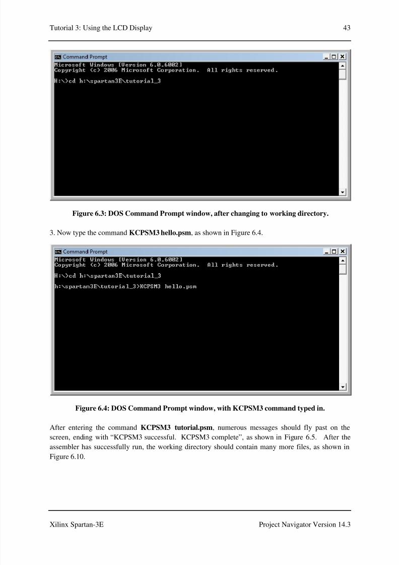
3. Now type the command KCPSM3 hello.psm, as shown in Figure 6.4.
Figure 6.4: DOS Command Prompt window, with KCPSM3 command typed in.
After entering the command KCPSM3 tutorial.psm, numerous messages should fly past on the
screen, ending with “KCPSM3 successful. KCPSM3 complete”, as shown in Figure 6.5. After the
assembler has successfully run, the working directory should contain many more files, as shown in
Figure 6.10.

8/10/2019 Spartan3E Tutorial 3
http://slidepdf.com/reader/full/spartan3e-tutorial-3 45/162
Tutorial 3: Using the LCD Display 44
Xilinx Spartan-3E Project Navigator Version 14.3
Figure 6.5: DOS Command Prompt window, after KCPSM3 successfully run.
4. Type exit to close the Command Prompt window.
6.2.2 64-bit Operating Systems
The KCPSM3 executable will only work on 32-bit operating systems. If you are using a 64-bit
machine and attempt to run KCPMS3 in a DOS Command Prompt window, the error message shownin Figure 6.6 will appear.
Figure 6.6: Error message which appears if it is attempted to run KCPSM3 on a 64-bit machine.

8/10/2019 Spartan3E Tutorial 3
http://slidepdf.com/reader/full/spartan3e-tutorial-3 46/162
Tutorial 3: Using the LCD Display 45
Xilinx Spartan-3E Project Navigator Version 14.3
One way to work around this and run KCPSM3 is to use the DOSbox software, which can be
downloaded from http://www.dosbox.com/ .
1. Download and run DOSBox.
2. Mount the working directory and change into this directory. When DOSbox is started up, acommand window which resembles the DOS Command Prompt window appears. However, it is first
necessary to mount the working directory to a drive letter before being able to enter this directory and
run programs. This is done with the mount command:
mount <drive_letter> <directory>
Figure 6.7 shows the commands entered to mount and change into the working directory. In this case,
the working directory is mounted as drive letter c. The command c: is then used to change into this
directory.
Figure 6.7: DOSBox window, commands entered to mount and change into the working
directory.
3. Now type the command KCPSM3 hello.psm, as shown in Figure 6.8.

8/10/2019 Spartan3E Tutorial 3
http://slidepdf.com/reader/full/spartan3e-tutorial-3 47/162
Tutorial 3: Using the LCD Display 46
Xilinx Spartan-3E Project Navigator Version 14.3
Figure 6.8: DOSBox window, with KCPSM3 command typed in.
After entering the command KCPSM3 hello.psm, numerous messages should fly past on the screen,
ending with “KCPSM3 successful. KCPSM3 complete”, as shown in Figure 6.9. After theassembler has successfully run, the working directory should contain many more files, as shown in
Figure 6.10.

8/10/2019 Spartan3E Tutorial 3
http://slidepdf.com/reader/full/spartan3e-tutorial-3 48/162

8/10/2019 Spartan3E Tutorial 3
http://slidepdf.com/reader/full/spartan3e-tutorial-3 49/162
Tutorial 3: Using the LCD Display 48
Xilinx Spartan-3E Project Navigator Version 14.3
Figure 6.10: Files in the working directory after KCPSM3 successfully run.

8/10/2019 Spartan3E Tutorial 3
http://slidepdf.com/reader/full/spartan3e-tutorial-3 50/162
Tutorial 3: Using the LCD Display 49
Xilinx Spartan-3E Project Navigator Version 14.3
6.3 Starting Project Navigator
Start the Project Navigator software by selecting:
Start→→→→All Programs→→→→XILINX Design Tools→→→→Xilinx ISE Design Suite 14.3→→→→ISE Design
Tools→→→→32 bit Project Navigator
or
Start→→→→All Programs→→→→XILINX Design Tools→→→→Xilinx ISE Design Suite 14.3→→→→ISE Design
Tools→→→→64 bit Project Navigator
depending on your system. The Xilinx Project Navigator software should start. The initial window
which appears on startup should appear as shown in Figure 6.11.
Figure 6.11: Project Navigator Software Startup Window.

8/10/2019 Spartan3E Tutorial 3
http://slidepdf.com/reader/full/spartan3e-tutorial-3 51/162
Tutorial 3: Using the LCD Display 50
Xilinx Spartan-3E Project Navigator Version 14.3
6.4 Creating a New Project
1. Select File→→→→New Project. The New Project Wizard will appear.
2. Type tutorial_3 in the Name: field.
3. Choose Location: and Working Directory: as the tutorial_3 working directory.
4. Verify that Top-level source type: is selected as HDL.
5. The properties should now be set as shown in Figure 6.12. Click Next to move to the Project
Settings page.
Figure 6.12: New Project Wizard, Create New Project Page.
6. Fill in the properties as follows:
• Evaluation Development Board: None Specified or Spartan-3E Starter Board
•
Product Category: All

8/10/2019 Spartan3E Tutorial 3
http://slidepdf.com/reader/full/spartan3e-tutorial-3 52/162
Tutorial 3: Using the LCD Display 51
Xilinx Spartan-3E Project Navigator Version 14.3
• Family: Spartan3E
• Device: XC3S500E
• Package: FG320
• Speed Grade: -4
•
Top-Level Source Type: HDL• Synthesis Tool: XST (VHDL/Verilog)
• Simulator: ISim (VHDL/Verilog)
• Preferred Language: VHDL
• Property Specification in Project File: Store All Values
• Manual Compile Order: unchecked
• VHDL Source Analysis Standard: VHDL-93
• Enable Message Filtering: unchecked
Note if you choose Evaluation Development Board as Spartan-3E Started Board, properties
from Product Category through to Speed will be filled in automatically. However, you mustmake sure that Preferred Language is set to VHDL.
The properties should now be filled in as shown in Figure 6.13.

8/10/2019 Spartan3E Tutorial 3
http://slidepdf.com/reader/full/spartan3e-tutorial-3 53/162
Tutorial 3: Using the LCD Display 52
Xilinx Spartan-3E Project Navigator Version 14.3
Figure 6.13: New Project Wizard, Project Settings Page.
7. Click Next to move to the Project Summary page, which will appear as shown in Figure 6.14.

8/10/2019 Spartan3E Tutorial 3
http://slidepdf.com/reader/full/spartan3e-tutorial-3 54/162
Tutorial 3: Using the LCD Display 53
Xilinx Spartan-3E Project Navigator Version 14.3
Figure 6.14: New Project Wizard, Project Summary Page.
8. Click Finish to exit the New Project Wizard.

8/10/2019 Spartan3E Tutorial 3
http://slidepdf.com/reader/full/spartan3e-tutorial-3 55/162
Tutorial 3: Using the LCD Display 54
Xilinx Spartan-3E Project Navigator Version 14.3
6.5 Adding Source Files
1. Select Project→→→→Add Source as shown in Figure 6.15. A window will appear allowing you to
choose one or more files.
Figure 6.15: Adding a source file to the project.
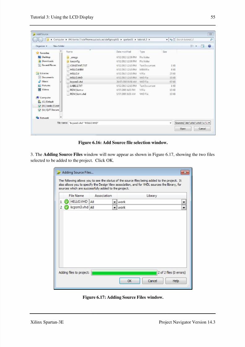
2. Select HELLO.VHD and kcpsm3.vhd as shown in Figure 6.16. Both files can be selected at once
by clicking on the first filename, holding down the CTRL key and clicking the second filename.
Alternatively, one file can be selected and steps 1-3 repeated for the second file.
8/10/2019 Spartan3E Tutorial 3
http://slidepdf.com/reader/full/spartan3e-tutorial-3 56/162
Tutorial 3: Using the LCD Display 55
Xilinx Spartan-3E Project Navigator Version 14.3
Figure 6.16: Add Source file selection window.
3. The Adding Source Files window will now appear as shown in Figure 6.17, showing the two files
selected to be added to the project. Click OK.
Figure 6.17: Adding Source Files window.

8/10/2019 Spartan3E Tutorial 3
http://slidepdf.com/reader/full/spartan3e-tutorial-3 57/162
Tutorial 3: Using the LCD Display 56
Xilinx Spartan-3E Project Navigator Version 14.3
As shown in Figure 6.18, kcpsm3 and hello will now appear in the Sources window. Double-clicking
on either filename in the Sources window will display the file in a tab.
Figure 6.18: kcpsm3 and hello in the Sources window.
Sour#es
W&n%ow

8/10/2019 Spartan3E Tutorial 3
http://slidepdf.com/reader/full/spartan3e-tutorial-3 58/162
Tutorial 3: Using the LCD Display 57
Xilinx Spartan-3E Project Navigator Version 14.3
6.6 hello.vhd and kcpsm3.vhd – Observations
1. Double-click on hello in the Sources window. This will display the source code in a tab, as shown
in Figure 6.19. It can be seen that Project Navigator colour codes the text of VDHL files, to make
them easier to read. Comment lines, which start with “- -” are displayed in green. Reserved words of
the VHDL language are displayed in blue, while VHDL types are displayed in red. Everything else
is left as black.
Figure 6.19: Source code for hello.vhd is displayed in a tab.
A close up of the code for the hello entity is shown in Figure 6.20. Note that this corresponds to the
Block Memory (Program) component of Figures 3.1 and 3.3.
Figure 6.20: hello entity.
he))o &n Sour#es
w&n%ow
Sour#e #o%e "orhe))o('h% $$ers
&n th&s t*

8/10/2019 Spartan3E Tutorial 3
http://slidepdf.com/reader/full/spartan3e-tutorial-3 59/162
Tutorial 3: Using the LCD Display 58
Xilinx Spartan-3E Project Navigator Version 14.3
2. Double-click on kcpsm3 in the Sources window, to display the source code for kcpsm3.vhd. A
close up of the code for the kspsm3 entity is shown in Figure 6.21. Note that this corresponds to the
KCPSM3 block of Figures 3.2 and 3.3.
Figure 6.21: kcpsm3 entity.

8/10/2019 Spartan3E Tutorial 3
http://slidepdf.com/reader/full/spartan3e-tutorial-3 60/162

8/10/2019 Spartan3E Tutorial 3
http://slidepdf.com/reader/full/spartan3e-tutorial-3 61/162
Tutorial 3: Using the LCD Display 60
Xilinx Spartan-3E Project Navigator Version 14.3
Figure 6.23: New Source Wizard, Select Source Type.
5. Click Next to go to the Define Module window.
6. The Define Module window appears as shown in Figure 6.24. We will define the ports (inputs and
outputs of the design) later. Click Next to move to the Summary page, as shown in Figure 6.25.

8/10/2019 Spartan3E Tutorial 3
http://slidepdf.com/reader/full/spartan3e-tutorial-3 62/162
Tutorial 3: Using the LCD Display 61
Xilinx Spartan-3E Project Navigator Version 14.3
Figure 6.24: New Source Wizard, Define Module.

8/10/2019 Spartan3E Tutorial 3
http://slidepdf.com/reader/full/spartan3e-tutorial-3 63/162
Tutorial 3: Using the LCD Display 62
Xilinx Spartan-3E Project Navigator Version 14.3
Figure 6.25: New Source Wizard, Summary.
8. Click Finish to exit the New Source Wizard.
As shown in Figure 6.26, top_level will now appear in the Sources window. Double-clicking on
top_level in the Sources window will display the file, top_level.vhd in a tab.

8/10/2019 Spartan3E Tutorial 3
http://slidepdf.com/reader/full/spartan3e-tutorial-3 64/162
Tutorial 3: Using the LCD Display 63
Xilinx Spartan-3E Project Navigator Version 14.3
Figure 6.26: top_level in the Sources window.
to$+)e'e) &n
Sour#es w&n%ow

8/10/2019 Spartan3E Tutorial 3
http://slidepdf.com/reader/full/spartan3e-tutorial-3 65/162
Tutorial 3: Using the LCD Display 64
Xilinx Spartan-3E Project Navigator Version 14.3
6.8 Editing the top_level Entity
1. Double-click on top_level in the Sources window to display the file, top_level.vhd in a tab. The
code for top_level.vhd is shown in Figure 6.27.
Figure 6.27: top_level.vhd, as displayed in Project Navigator, before editing.
The code in Figure 6.27 contains an entity and an architecture section. The entity section defines
the inputs and outputs of this hardware block. The entity and architecture sections still need to be
written for this module.
2. Replace the entity and architecture blocks in Figure 6.27 with the code in Figure 6.28(a)-(d).
Alternatively, download the file top_level_init.vhd, available for download with this tutorial, and
copy the code from it. The code in Figure 6.28 is a trimmed down version of the Initial Design for
the Spartan-3E FPGA Starter Kit Board (the original design shipped with the board), downloaded
from [8].
For reference the complete code for top_level.vhd is listed in Appendix A. Note that where VDHL
code is listed in this tutorial, the same colour coding as Project Navigator is used, to assist withreadability.
3. Save the file by selecting File→ Save from the main menu.
ent&t,
r#h&te#ture

8/10/2019 Spartan3E Tutorial 3
http://slidepdf.com/reader/full/spartan3e-tutorial-3 66/162
8/10/2019 Spartan3E Tutorial 3
http://slidepdf.com/reader/full/spartan3e-tutorial-3 67/162
Tutorial 3: Using the LCD Display 66
Xilinx Spartan-3E Project Navigator Version 14.3
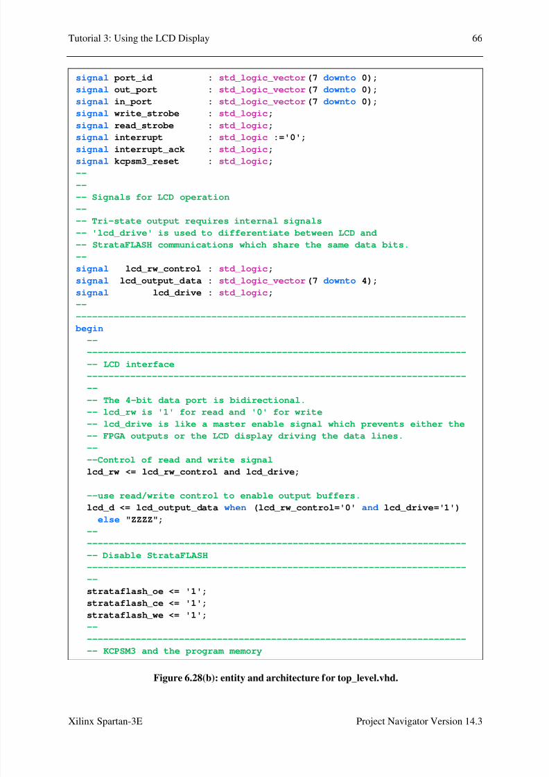
Figure 6.28(b): entity and architecture for top_level.vhd.
signal port_id : std_logic_vector(7 downto 0);
signal out_port : std_logic_vector(7 downto 0);
signal in_port : std_logic_vector(7 downto 0);
signal write_strobe : std_logic;
signal read_strobe : std_logic;
signal interrupt : std_logic :='0';signal interrupt_ack : std_logic;
signal kcpsm3_reset : std_logic;
--
--
-- Signals for LCD operation
--
-- Tri-state output requires internal signals
-- 'lcd_drive' is used to differentiate between LCD and
-- StrataFLASH communications which share the same data bits.
--
signal lcd_rw_control : std_logic;signal lcd_output_data : std_logic_vector(7 downto 4);
signal lcd_drive : std_logic;
--
------------------------------------------------------------------------
begin
--
----------------------------------------------------------------------
-- LCD interface
----------------------------------------------------------------------
--
-- The 4-bit data port is bidirectional.
-- lcd_rw is '1' for read and '0' for write
-- lcd_drive is like a master enable signal which prevents either the
-- FPGA outputs or the LCD display driving the data lines.
--
--Control of read and write signal
lcd_rw <= lcd_rw_control and lcd_drive;
--use read/write control to enable output buffers.
lcd_d <= lcd_output_data when (lcd_rw_control='0' and lcd_drive='1')
else "ZZZZ";
--
------------------------------------------------------------------------ Disable StrataFLASH
----------------------------------------------------------------------
--
strataflash_oe <= '1';
strataflash_ce <= '1';
strataflash_we <= '1';
--
----------------------------------------------------------------------
-- KCPSM3 and the program memory
8/10/2019 Spartan3E Tutorial 3
http://slidepdf.com/reader/full/spartan3e-tutorial-3 68/162
Tutorial 3: Using the LCD Display 67
Xilinx Spartan-3E Project Navigator Version 14.3
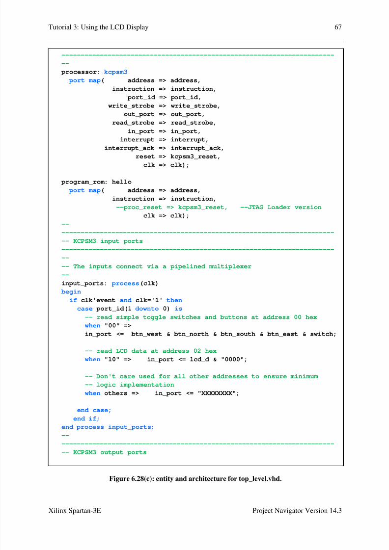
Figure 6.28(c): entity and architecture for top_level.vhd.
-----------------------------------------------------------------------
--
processor: kcpsm3
port map( address => address,
instruction => instruction,
port_id => port_id,write_strobe => write_strobe,
out_port => out_port,
read_strobe => read_strobe,
in_port => in_port,
interrupt => interrupt,
interrupt_ack => interrupt_ack,
reset => kcpsm3_reset,
clk => clk);
program_rom: hello
port map( address => address,instruction => instruction,
--proc_reset => kcpsm3_reset, --JTAG Loader version
clk => clk);
--
-----------------------------------------------------------------------
-- KCPSM3 input ports
-----------------------------------------------------------------------
--
-- The inputs connect via a pipelined multiplexer
--
input_ports: process(clk)
begin
if clk'event and clk='1' then
case port_id(1 downto 0) is
-- read simple toggle switches and buttons at address 00 hex
when "00" =>
in_port <= btn_west & btn_north & btn_south & btn_east & switch;
-- read LCD data at address 02 hex
when "10" => in_port <= lcd_d & "0000";
-- Don't care used for all other addresses to ensure minimum
-- logic implementationwhen others => in_port <= "XXXXXXXX";
end case;
end if;
end process input_ports;
--
-----------------------------------------------------------------------
-- KCPSM3 output ports
8/10/2019 Spartan3E Tutorial 3
http://slidepdf.com/reader/full/spartan3e-tutorial-3 69/162
Tutorial 3: Using the LCD Display 68
Xilinx Spartan-3E Project Navigator Version 14.3
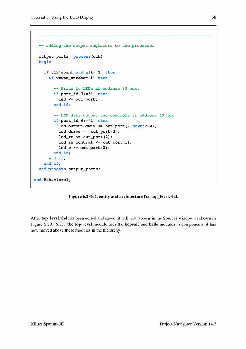
Figure 6.28(d): entity and architecture for top_level.vhd.
After top_level.vhd has been edited and saved, it will now appear in the Sources window as shown in
Figure 6.29. Since the top_level module uses the kcpsm3 and hello modules as components, it has
now moved above these modules in the hierarchy.
-----------------------------------------------------------------------
--
-- adding the output registers to the processor
--
output_ports: process(clk)
begin
if clk'event and clk='1' then
if write_strobe='1' then
-- Write to LEDs at address 80 hex.
if port_id(7)='1' then
led <= out_port;
end if;
-- LCD data output and controls at address 40 hex.
if port_id(6)='1' then lcd_output_data <= out_port(7 downto 4);
lcd_drive <= out_port(3);
lcd_rs <= out_port(2);
lcd_rw_control <= out_port(1);
lcd_e <= out_port(0);
end if;
end if;
end if;
end process output_ports;
end Behavioral;

8/10/2019 Spartan3E Tutorial 3
http://slidepdf.com/reader/full/spartan3e-tutorial-3 70/162
Tutorial 3: Using the LCD Display 69
Xilinx Spartan-3E Project Navigator Version 14.3
Figure 6.29: top_level in the Sources window.
to$+)e'e) &n
Sour#es w&n%ow

8/10/2019 Spartan3E Tutorial 3
http://slidepdf.com/reader/full/spartan3e-tutorial-3 71/162
Tutorial 3: Using the LCD Display 70
Xilinx Spartan-3E Project Navigator Version 14.3
6.9 top_level.vhd – Code
This section briefly outlines different parts of the code of the entity and architecture blocks of
top_level.vhd, and their functions.
The top_level entity defines the inputs and outputs of the module, as shown in Figure 6.30.
Figure 6.30: top_level entity.
At the start of the architecture block, the kcpsm3 and hello components that will be used are declared,
as shown in Figure 6.31.
entity top_level is Port ( led : out std_logic_vector(7 downto 0);
strataflash_oe : out std_logic;
strataflash_ce : out std_logic;strataflash_we : out std_logic;
switch : in std_logic_vector(3 downto 0); btn_north : in std_logic; btn_east : in std_logic;
btn_south : in std_logic; btn_west : in std_logic;
lcd_d : inout std_logic_vector(7 downto 4);lcd_rs : out std_logic;lcd_rw : out std_logic;lcd_e : out std_logic;clk : in std_logic);
end top_level;

8/10/2019 Spartan3E Tutorial 3
http://slidepdf.com/reader/full/spartan3e-tutorial-3 72/162

8/10/2019 Spartan3E Tutorial 3
http://slidepdf.com/reader/full/spartan3e-tutorial-3 73/162
Tutorial 3: Using the LCD Display 72
Xilinx Spartan-3E Project Navigator Version 14.3
Figure 6.32: Signal declarations.
The code in Figures 6.33 to 6.36 appears between the begin and end statements in the architecture
block. In Figure 6.33, signal control for the LCD interface is shown. Signals are also sent to disable
the StrataFlash.
-------------------------------------------------------------------------
---- Signals used to connect KCPSM3 to program ROM and I/O logic--signal address : std_logic_vector(9 downto 0);
signal instruction : std_logic_vector(17 downto 0);signal port_id : std_logic_vector(7 downto 0);
signal out_port : std_logic_vector(7 downto 0);
signal in_port : std_logic_vector(7 downto 0);
signal write_strobe : std_logic;
signal read_strobe : std_logic;
signal interrupt : std_logic :='0';
signal interrupt_ack : std_logic;
signal kcpsm3_reset : std_logic;
--
--
-- Signals for LCD operation
---- Tri-state output requires internal signals
-- 'lcd_drive' is used to differentiate between LCD and
-- StrataFLASH communications which share the same data bits.
--
signal lcd_rw_control : std_logic;
signal lcd_output_data : std_logic_vector(7 downto 4);
signal lcd_drive : std_logic;
--
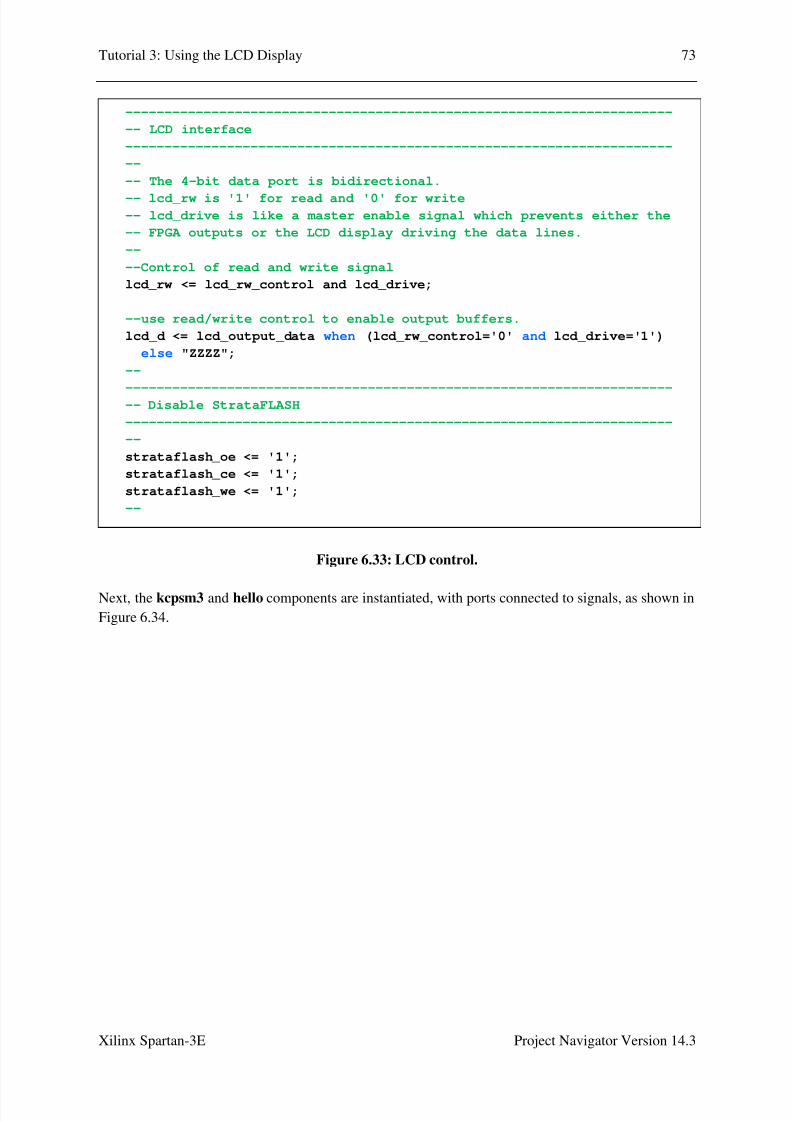
8/10/2019 Spartan3E Tutorial 3
http://slidepdf.com/reader/full/spartan3e-tutorial-3 74/162
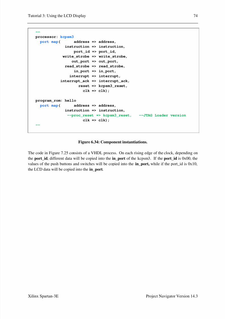
8/10/2019 Spartan3E Tutorial 3
http://slidepdf.com/reader/full/spartan3e-tutorial-3 75/162
Tutorial 3: Using the LCD Display 74
Xilinx Spartan-3E Project Navigator Version 14.3
Figure 6.34: Component instantiations.
The code in Figure 7.25 consists of a VHDL process. On each rising edge of the clock, depending on
the port_id, different data will be copied into the in_port of the kcpsm3. If the port_id is 0x00, the
values of the push buttons and switches will be copied into the in_port, while if the port_id is 0x10,
the LCD data will be copied into the in_port.
--
processor: kcpsm3
port map( address => address,
instruction => instruction,
port_id => port_id,
write_strobe => write_strobe,out_port => out_port,
read_strobe => read_strobe,
in_port => in_port,
interrupt => interrupt,
interrupt_ack => interrupt_ack,
reset => kcpsm3_reset,
clk => clk);
program_rom: hello
port map( address => address,
instruction => instruction,--proc_reset => kcpsm3_reset, --JTAG Loader version
clk => clk);
--

8/10/2019 Spartan3E Tutorial 3
http://slidepdf.com/reader/full/spartan3e-tutorial-3 76/162
Tutorial 3: Using the LCD Display 75
Xilinx Spartan-3E Project Navigator Version 14.3
Figure 6.35: Input ports.
The code in Figure 6.36 consists of a VHDL process. On each rising edge of the clock, depending on
the port_id, different data will be read from the out_port of the kcpsm3. If the port_id is 0x80, then
out_port will be read into led, while if the port_id is 0x40, then various bits of out_port will be read
into LCD control signals.
-----------------------------------------------------------------------
-- KCPSM3 input ports
-----------------------------------------------------------------------
--
-- The inputs connect via a pipelined multiplexer
--input_ports: process(clk)
begin
if clk'event and clk='1' then
case port_id(1 downto 0) is
-- read simple toggle switches and buttons at address 00 hex
when "00" =>
in_port <= btn_west & btn_north & btn_south & btn_east & switch;
-- read LCD data at address 02 hex
when "10" => in_port <= lcd_d & "0000";
-- Don't care used for all other addresses to ensure minimum
-- logic implementation
when others => in_port <= "XXXXXXXX";
end case;
end if;
end process input_ports;
--

8/10/2019 Spartan3E Tutorial 3
http://slidepdf.com/reader/full/spartan3e-tutorial-3 77/162
Tutorial 3: Using the LCD Display 76
Xilinx Spartan-3E Project Navigator Version 14.3
Figure 6.36: Output ports.
-----------------------------------------------------------------------
--
-- adding the output registers to the processor
--
output_ports: process(clk)
begin
if clk'event and clk='1' then
if write_strobe='1' then
-- Write to LEDs at address 80 hex.
if port_id(7)='1' then
led <= out_port;
end if;
-- LCD data output and controls at address 40 hex.
if port_id(6)='1' then lcd_output_data <= out_port(7 downto 4);
lcd_drive <= out_port(3);
lcd_rs <= out_port(2);
lcd_rw_control <= out_port(1);
lcd_e <= out_port(0);
end if;
end if;
end if;
end process output_ports;

8/10/2019 Spartan3E Tutorial 3
http://slidepdf.com/reader/full/spartan3e-tutorial-3 78/162
Tutorial 3: Using the LCD Display 77
Xilinx Spartan-3E Project Navigator Version 14.3
6.10 Syntax Checking
Syntax checking can be done at this stage, to check that the VHDL code has been entered correctly.
The following steps refer to the Project Navigator screen of Figure 6.37.
1.
Verify that the Implementation check box toward the top left of the screen has been selected.
2. Verify that the Design tab has been selected.
3. Click on the ‘+’ next to Synthesize – XST. This will expand out to show various items, including
Check Syntax.
Figure 6.37: Portion of Project Navigator screen with Synthesize – XST expanded.
Des&n t*
S,nthes&.e - ST
Che# S,nt1
2!$)e!entt&on

8/10/2019 Spartan3E Tutorial 3
http://slidepdf.com/reader/full/spartan3e-tutorial-3 79/162
Tutorial 3: Using the LCD Display 78
Xilinx Spartan-3E Project Navigator Version 14.3
4. Double-click on Check Syntax. After some time, a green tick should appear beside Check
Syntax, as shown in Figure 6.38. If instead, a red cross appears, this means a syntax error has
been found. Any errors should be fixed before proceeding.
Figure 6.38: A green tick next to Check Syntax shows that no errors were found.
6.11 Pin AssignmentRecall that the VHDL code for the top_level entity is:
We wish to connect the inputs and outputs of the top_level entity to the switches, buttons, LEDs,
clock and LCD interface on the Spartan-3E board.
entity top_level is
Port ( led : out std_logic_vector(7 downto 0);
strataflash_oe : out std_logic;strataflash_ce : out std_logic;
strataflash_we : out std_logic;switch : in std_logic_vector(3 downto 0);
btn_north : in std_logic; btn_east : in std_logic;
btn_south : in std_logic; btn_west : in std_logic;
lcd_d : inout std_logic_vector(7 downto 4);
lcd_rs : out std_logic;
lcd_rw : out std_logic;lcd_e : out std_logic;
clk : in std_logic);end top_level;
Green t&# ne1t to
Che# S,nt1

8/10/2019 Spartan3E Tutorial 3
http://slidepdf.com/reader/full/spartan3e-tutorial-3 80/162
Tutorial 3: Using the LCD Display 79
Xilinx Spartan-3E Project Navigator Version 14.3
For each input and output port of the top_level entity, Table 6.1 lists the name of the device on the
Spartan-3E board that we wish to connect the port to, a description of what it physically corresponds
to (clock, slider switch, push button or LED), and the FPGA pin number that it is connected to. This
information comes from the Spartan-3E FPGA Starter Kit Board User Guide [1].
Port name Spartan-3E signalname
Description FPGA pin
led(7) LD7 LED F9
led(6) LD6 LED E9
led(5) LD5 LED D11
led(4) LD4 LED C11
led(3) LD3 LED F11
led(2) LD2 LED E11
led(1) LD1 LED E12
led(0) LD0 LED F12
strataflash_oe SF_OE Strataflash chip enable C18
strataflash_ce SF_CE0 Strataflash chip enable D16strataflash_we SF_WE Strataflash write enable D17
switch(3) SW3 Slider switch N17
switch(2) SW2 Slider switch H18
switch(1) SW1 Slider switch L14
switch(0) SW0 Slider switch L13
btn_north BTN_NORTH Push button V4
btn_east BTN_EAST Push button H13
btn_south BTN_SOUTH Push button K17
btn_west BTN_WEST Push button D18
lcd_d(7) SF_D<11> LCD data bit DB7 M15
lcd_d(6) SF_D<10> LCD data bit DB6 P17lcd_d(5) SF_D<9> LCD data bit DB5 R16
lcd_d(4) SF_D<8> LCD data bit DB4 R15
lcd_rs LCD_RS LCD Register Select L18
lcd_rw LCD_RW LCD Read/Write Control L17
lcd_e LCD_E LCD Read/Write Enable M18
clk CLK_50MHZ Clock C9
Table 6.1: Input/output ports of the top_level entity; and the name, description and FPGA pin
no. that the ports will be connected to.
The following steps are used to connect the inputs and outputs to the switches, buttons, LEDs, clock
and LCD interface on the Spartan-3E board:
1. As shown in Figure 6.39, click on the ‘+’ next to User Constraints. This will expand out to
show various items, including I/O Pin Planning (PlanAhead) – Pre-Synthesis.

8/10/2019 Spartan3E Tutorial 3
http://slidepdf.com/reader/full/spartan3e-tutorial-3 81/162
Tutorial 3: Using the LCD Display 80
Xilinx Spartan-3E Project Navigator Version 14.3
Figure 6.39: Portion of Project Navigator screen, with User Constraints expanded.
2. Double-click on I /O Pin Planning (PlanAhead) – Pre-Synthesis. The first time this is done, the
window of Figure 6.40 will appear, asking whether it is OK to create a UCF file. Click Yes.
Figure 6.40: Dialog Box asking if you wish to create an Implementation Constraint File.
3. After clicking Yes in Figure 6.40, the PlanAhead window of Figure 6.41 will appear. Click on
the I/O Ports tab, and then the float frame icon. This displays the I/O Ports in a separatewindow, as shown in Figure 6.42.
User Constr&nts
2/O P&n P)nn&n
P)nAhe%4 5
Pre-S,nthes&s

8/10/2019 Spartan3E Tutorial 3
http://slidepdf.com/reader/full/spartan3e-tutorial-3 82/162
Tutorial 3: Using the LCD Display 81
Xilinx Spartan-3E Project Navigator Version 14.3
Figure 6.41: Initial appearance of PlanAhead window.
4. Click on the ‘+’ next to lcd_d(4), led(8), switch(4) and Scalar ports(11) in Figure 6.42. This
will display all individual input/outputs as shown in Figure 5.33.
Figure 6.42: I/O Ports displayed in a separate window.
2/O Ports t* F)ot Fr!e 2#on
S'e *utton

8/10/2019 Spartan3E Tutorial 3
http://slidepdf.com/reader/full/spartan3e-tutorial-3 83/162
Tutorial 3: Using the LCD Display 82
Xilinx Spartan-3E Project Navigator Version 14.3
Figure 6.43: I/O Ports window with individual ports expanded.
5. Enter the Site, I/O Std, Drive Strength, Slew Type and Pull Type columns, with the values
given in Table 6.2. The Bank and Vcco columns will be filled in automatically when the Site
and I/O Std columns respectively are filled in.

8/10/2019 Spartan3E Tutorial 3
http://slidepdf.com/reader/full/spartan3e-tutorial-3 84/162
Tutorial 3: Using the LCD Display 83
Xilinx Spartan-3E Project Navigator Version 14.3
Port Site I/O Std Drive
Strength
Slew Type Pull Type
lcd_d(7) M15 LVCMOS33 4 SLOW NONE
lcd_d(6) P17 LVCMOS33 4 SLOW NONE
lcd_d(5) R16 LVCMOS33 4 SLOW NONElcd_d(4) R15 LVCMOS33 4 SLOW NONE
led(7) F9 LVTTL 8 SLOW NONE
led(6) E9 LVTTL 8 SLOW NONE
led(5) D11 LVTTL 8 SLOW NONE
led(4) C11 LVTTL 8 SLOW NONE
led(3) F11 LVTTL 8 SLOW NONE
led(2) E11 LVTTL 8 SLOW NONE
led(1) E12 LVTTL 8 SLOW NONE
led(0) F12 LVTTL 8 SLOW NONE
switch(3) N17 LVTTL PULLUP
switch(2) H18 LVTTL PULLUPswitch(1) L14 LVTTL PULLUP
switch(0) L13 LVTTL PULLUP
btn_east H13 LVTTL PULLDOWN
btn_north V4 LVTTL PULLDOWN
btn_south K17 LVTTL PULLDOWN
btn_west D18 LVTTL PULLDOWN
clk C9 LVCMOS33 NONE
lcd_e M18 LVCMOS33 4 SLOW NONE
lcd_rs L18 LVCMOS33 4 SLOW NONE
lcd_rw L17 LVCMOS33 4 SLOW NONE
strataflash_ce D16 LVCMOS33 4 SLOW NONE
strataflash_oe C18 LVCMOS33 4 SLOW NONE
strataflash_we D17 LVCMOS33 4 SLOW NONE
Table 6.2: Values to enter in the I/O Ports window.
The I/O Ports window should now appear as shown in Figure 6.44.
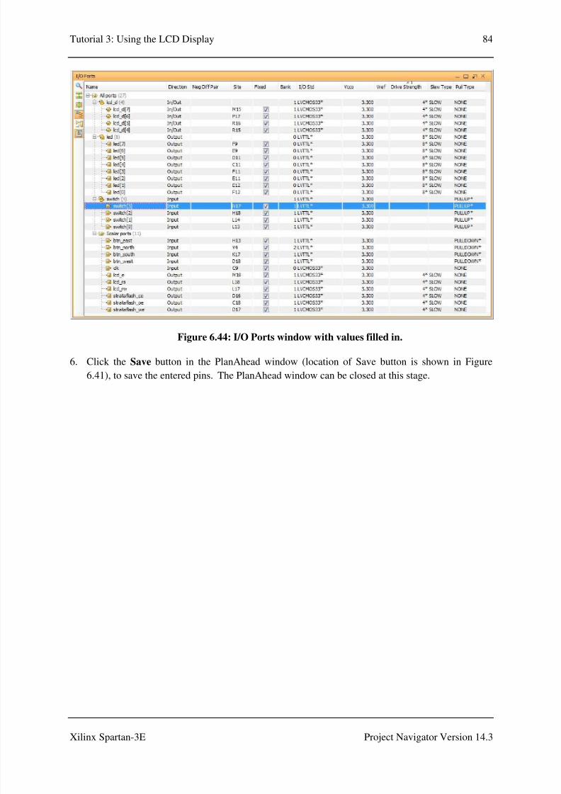
8/10/2019 Spartan3E Tutorial 3
http://slidepdf.com/reader/full/spartan3e-tutorial-3 85/162
Tutorial 3: Using the LCD Display 84
Xilinx Spartan-3E Project Navigator Version 14.3
Figure 6.44: I/O Ports window with values filled in.
6. Click the Save button in the PlanAhead window (location of Save button is shown in Figure
6.41), to save the entered pins. The PlanAhead window can be closed at this stage.

8/10/2019 Spartan3E Tutorial 3
http://slidepdf.com/reader/full/spartan3e-tutorial-3 86/162

8/10/2019 Spartan3E Tutorial 3
http://slidepdf.com/reader/full/spartan3e-tutorial-3 87/162
Tutorial 3: Using the LCD Display 86
Xilinx Spartan-3E Project Navigator Version 14.3
2. Double-click on Implement Design. This will first cause Synthesize – XST to run. Next,
Translate, Map and Place & Route will run in turn. As each stage is completed, a green tick will
appear next to it. If there are warning messages at any stage, a yellow icon with an exclamation
mark will appear. The user can inspect these warning messages and decide whether they are
critical to the design. After all three stages are complete, the Project Navigator screen will appear
as shown in Figure 6.46.
Figure 6.46: Portion of Project Navigator screen, with Implement Design expanded, after
Translate, Map and Place & Route have successfully been run.
2n%&#tes there
were wrn&n
!esses

8/10/2019 Spartan3E Tutorial 3
http://slidepdf.com/reader/full/spartan3e-tutorial-3 88/162
Tutorial 3: Using the LCD Display 87
Xilinx Spartan-3E Project Navigator Version 14.3
6.13 Download Design to Board
The next steps involve generating the program file, and downloading it to the Spartan-3E board using
iMPACT.
1.
As shown in Figure 6.47, click on the ‘+’ next to Configure Target Device. This will expand out
to show the Manage Configuration Project (iMPACT) option.
Figure 6.47: Portion of Project Navigator screen, with Implement Design expanded.
Generte
Pror!!&n F&)e
Con"&ure Tret
De'&#e
6ne Con"&urt&on
Pro7e#t &6PACT4

8/10/2019 Spartan3E Tutorial 3
http://slidepdf.com/reader/full/spartan3e-tutorial-3 89/162
Tutorial 3: Using the LCD Display 88
Xilinx Spartan-3E Project Navigator Version 14.3
2. Double-click on Generate Programming File. When this has successfully run, a green tick will
appear next to Generate Programming File as shown in Figure 6.48.
3. Connect the power cable and the USB cable to the Spartan-3E board (refer to Figure 2.1 for
locations of the power and USB plugs). Plug the USB cable from the Spartan-3E into the PC, and
make sure the Sparan-3E board is switched on.
Figure 6.48: Portion of Project Navigator screen, after Generate Programming File has
successfully been run.

8/10/2019 Spartan3E Tutorial 3
http://slidepdf.com/reader/full/spartan3e-tutorial-3 90/162
Tutorial 3: Using the LCD Display 89
Xilinx Spartan-3E Project Navigator Version 14.3
4. Double-click on Manage Configuration Project (iMPACT). The iMPACT window should
appear as shown in Figure 6.49.
Figure 6.49: The initial iMPACT window.

8/10/2019 Spartan3E Tutorial 3
http://slidepdf.com/reader/full/spartan3e-tutorial-3 91/162
Tutorial 3: Using the LCD Display 90
Xilinx Spartan-3E Project Navigator Version 14.3
5. Double-click on Boundary Scan as shown in Figure 6.50. The message “Right click to Add
Device or Initialize JTAG Chain” should appear to the right.
Figure 6.50: iMPACT window, after double-clicking on Boundary Scan.
Boun%r, S#n 6esse $$ers
here

8/10/2019 Spartan3E Tutorial 3
http://slidepdf.com/reader/full/spartan3e-tutorial-3 92/162
Tutorial 3: Using the LCD Display 91
Xilinx Spartan-3E Project Navigator Version 14.3
6. Right click on the text “Right click to Add Device or Initialize JTAG Chain”, and select Initialise
Chain, as shown in Figure 6.51.
Figure 6.51: iMPACT window, showing Initialize Chain selected.

8/10/2019 Spartan3E Tutorial 3
http://slidepdf.com/reader/full/spartan3e-tutorial-3 93/162
Tutorial 3: Using the LCD Display 92
Xilinx Spartan-3E Project Navigator Version 14.3
7. After a while, a picture of a “chain” should appear, along with the message Identify Succeeded in
a blue box (Figure 6.52). The first chip, the xc3s500e, is the FPGA chip that we wish to program.
The other two, xcf04s and xc2c64a, are other chips on the board that will be bypassed.
A dialog box, asking “Do you wish to continue and select configuration file(s)?” will appear, as
shown in Figure 6.52. Click Yes.
Figure 6.52: iMPACT window, assign configuration files.

8/10/2019 Spartan3E Tutorial 3
http://slidepdf.com/reader/full/spartan3e-tutorial-3 94/162
Tutorial 3: Using the LCD Display 93
Xilinx Spartan-3E Project Navigator Version 14.3
8. The Assign New Configuration File window will appear (Figure 6.53). Select the file
“top_level.bit”, and click Open. This associates the file top_level.bit with the xc3s500e.
Figure 6.53: iMPACT window, assigning the configuration file for the xc3e500e.

8/10/2019 Spartan3E Tutorial 3
http://slidepdf.com/reader/full/spartan3e-tutorial-3 95/162
Tutorial 3: Using the LCD Display 94
Xilinx Spartan-3E Project Navigator Version 14.3
9. A message stating “This device supports attached flash PROMs. Do you want to attach an SPI or
BPI PROM to this device?” will appear (Figure 6.54). This is not needed for this design. Click
No.
Figure 6.54: iMPACT window, dialog box asking if we wish to attach an SPI or BPI PROM.

8/10/2019 Spartan3E Tutorial 3
http://slidepdf.com/reader/full/spartan3e-tutorial-3 96/162
Tutorial 3: Using the LCD Display 95
Xilinx Spartan-3E Project Navigator Version 14.3
10. The Assign New Configuration File window will appear again (Figure 6.55). In this case click
Bypass. This ensures that the xcf04s is bypassed.
Figure 6.55: iMPACT window, bypassing the xcf04s.

8/10/2019 Spartan3E Tutorial 3
http://slidepdf.com/reader/full/spartan3e-tutorial-3 97/162
Tutorial 3: Using the LCD Display 96
Xilinx Spartan-3E Project Navigator Version 14.3
11. The Assign New Configuration File window will appear yet again (Figure 6.56). Again click
Bypass. This ensures that the xc2c64a is bypassed.
Figure 6.56: iMPACT window, bypassing the xc2c64a.

8/10/2019 Spartan3E Tutorial 3
http://slidepdf.com/reader/full/spartan3e-tutorial-3 98/162
Tutorial 3: Using the LCD Display 97
Xilinx Spartan-3E Project Navigator Version 14.3
12. A window entitled Device Programming Properties – Device 1 Programming Properties will
appear (Figure 6.57). Click OK.
Figure 6.57: iMPACT window, Device Programming Properties dialog box.

8/10/2019 Spartan3E Tutorial 3
http://slidepdf.com/reader/full/spartan3e-tutorial-3 99/162
Tutorial 3: Using the LCD Display 98
Xilinx Spartan-3E Project Navigator Version 14.3
13. The iMPACT window should now appear as shown in Figure 6.58. Right click on the xc3e500e
chip (Figure 6.59) and select Program.
Figure 6.58: iMPACT window, showing the device chain.
Figure 6.59: iMPACT window, options which appear when right clicking on the xc3s500e.
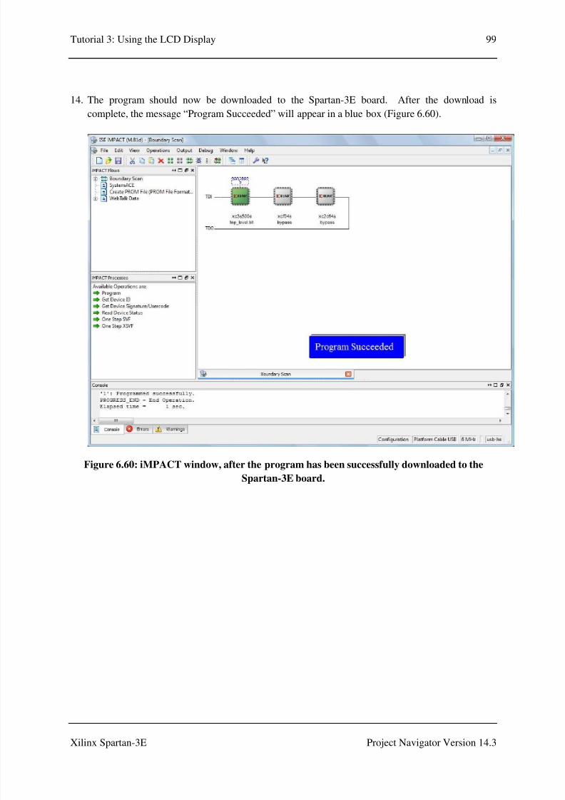
8/10/2019 Spartan3E Tutorial 3
http://slidepdf.com/reader/full/spartan3e-tutorial-3 100/162
Tutorial 3: Using the LCD Display 99
Xilinx Spartan-3E Project Navigator Version 14.3
14. The program should now be downloaded to the Spartan-3E board. After the download is
complete, the message “Program Succeeded” will appear in a blue box (Figure 6.60).
Figure 6.60: iMPACT window, after the program has been successfully downloaded to the
Spartan-3E board.

8/10/2019 Spartan3E Tutorial 3
http://slidepdf.com/reader/full/spartan3e-tutorial-3 101/162
Tutorial 3: Using the LCD Displ
Xilinx Spartan-3E
6.14 Running the Pr
The Spartan-3E board after do
displays the words “Hello Worl
when slider switches are in the
Figure 6.61: The S
ay
Project N
gram on the Spartan-3E Board
nloading the program is shown in Figure 6.6
” on the first and second line. Also, correspon
N position or push buttons are pressed.
artan-3E board with the program running fo
SW38SW98SW:8SW
100
vigator Version 14.3
1. The LCD screen
ing LEDs will be lit
Part A.
LD;-LD0

8/10/2019 Spartan3E Tutorial 3
http://slidepdf.com/reader/full/spartan3e-tutorial-3 102/162
Tutorial 3: Using the LCD Display 101
Xilinx Spartan-3E Project Navigator Version 14.3
7.0 Procedure Part B – Creating Custom Characters
7.1 Edit the .psm file
1. Open your file hello.psm in a text editor.
2. Replace the statements between cold_start: and JUMP Main in Figure 6.1 with the code of Figure
7.1.
Figure 7.1: Main program loop for Part B.
2. Replace the Disp_mesg subroutine in Figure 6.1 with the code of Figure 7.2.
Figure 7.2: Disp_mesg subroutine for Part B.
3. Add the Disp_cust_chars and Setup_cust_chars subroutines, shown in Figures 7.3 and 7.4. The
Disp_Hello_World subroutine is unchanged.
Disp_mesg: LOAD s5, 80 ;Line 1 position 1
CALL LCD_write_inst8
CALL Disp_Hello_World ;12 chars
CALL Disp_cust_chars ; 4 chars
LOAD s5, C0 ;Line 2 position 1
CALL LCD_write_inst8
CALL Disp_Hello_World ;12 chars
CALL Disp_cust_chars ; 4 chars
RETURN
cold_start: CALL LCD_reset ;initialise LCD display
CALL Setup_cust_chars ;set up customised characters
CALL Disp_mesg ;display message
;
Main: INPUT s7, switch_port ;read in switches
OUTPUT s7, LED_port ;output to LEDs
JUMP Main

8/10/2019 Spartan3E Tutorial 3
http://slidepdf.com/reader/full/spartan3e-tutorial-3 103/162
Tutorial 3: Using the LCD Display 102
Xilinx Spartan-3E Project Navigator Version 14.3
Figure 7.3: Disp_cust_chars subroutine for Part B.
Disp_cust_chars: LOAD s5, 00 ;CG RAM address 00, cust char
CALL LCD_write_data
CALL LCD_write_data
LOAD s5, 01 ;CG RAM address 01, cust char
CALL LCD_write_data
LOAD s5, 20 ;space
CALL LCD_write_data
RETURN
;

8/10/2019 Spartan3E Tutorial 3
http://slidepdf.com/reader/full/spartan3e-tutorial-3 104/162
Tutorial 3: Using the LCD Display 103
Xilinx Spartan-3E Project Navigator Version 14.3
Figure 7.4: Setup_cust_chars subroutine for Part B.
For reference the modified hello.psm is listed in Appendix B.
The subroutine Setup_cust_chars initialises two customised characters, at addresses 0x00 and 0x01
in the CG RAM. Tables 7.1 and 7.2 show the two customised characters. The subroutine
Disp_cust_chars displays two of the character at 0x00, followed by the character at 0x01, followed
by a space.
Setup_cust_chars: LOAD s5, 40 ;set CG RAM address 00
CALL LCD_write_inst8
LOAD s5, 00 ;line 1
CALL LCD_write_data
LOAD s5, 0E ;line 2CALL LCD_write_data
LOAD s5, 1F ;line 3
CALL LCD_write_data
LOAD s5, 15 ;line 4
CALL LCD_write_data
LOAD s5, 1F ;line 5
CALL LCD_write_data
LOAD s5, 1F ;line 6
CALL LCD_write_data
LOAD s5, 15 ;line 7
CALL LCD_write_dataLOAD s5, 00 ;line 8
CALL LCD_write_data
LOAD s5, 48 ;set CG RAM address 01
CALL LCD_write_inst8
LOAD s5, 0E ;line 1
CALL LCD_write_data
LOAD s5, 1F ;line 2
CALL LCD_write_data
LOAD s5, 0F ;line 3
CALL LCD_write_data
LOAD s5, 07 ;line 4
CALL LCD_write_data
LOAD s5, 0F ;line 5
CALL LCD_write_data
LOAD s5, 1F ;line 6
CALL LCD_write_data
LOAD s5, 0E ;line 7
CALL LCD_write_data
LOAD s5, 00 ;line 8
CALL LCD_write_data
RETURN

8/10/2019 Spartan3E Tutorial 3
http://slidepdf.com/reader/full/spartan3e-tutorial-3 105/162
Tutorial 3: Using the LCD Display 104
Xilinx Spartan-3E Project Navigator Version 14.3
Disp_mesg positions the cursor at line 1, position 1, and then writes the text “Hello World” followed
by the custom characters to line 1 of the LCD. Next, it positions the cursor at line 2 position 1 and
repeats the process to display the same message on line 2.
Upper Nibble Lower NibbleWrite Data to CG RAM of DD RAM
A5 A4 A3 A2 A1 A0 D7 D6 D5 D4 D3 D2 D1 D0
Character Address Row Address Don’t Care Character Bitmap
0 0 0 0 0 0 - - - 0 0 0 0 0
0 0 0 0 0 1 - - - 0 1 1 1 0
0 0 0 1 1 0 - - - 1 1 1 1 1
0 0 0 0 1 1 - - - 1 0 1 0 1
0 0 0 1 0 0 - - - 1 1 1 1 1
0 0 0 1 0 1 - - - 1 1 1 1 1
0 0 0 1 1 0 - - - 1 0 1 0 1
0 0 0 1 1 1 - - - 0 0 0 0 0
Table 7.1: Example custom character stored in CG RAM address 0x00.
Upper Nibble Lower Nibble
Write Data to CG RAM of DD RAM
A5 A4 A3 A2 A1 A0 D7 D6 D5 D4 D3 D2 D1 D0
Character Address Row Address Don’t Care Character Bitmap
0 0 1 0 0 0 - - - 0 1 1 1 0
0 0 1 0 0 1 - - - 1 1 1 1 1
0 0 1 1 1 0 - - - 0 1 1 1 10 0 1 0 1 1 - - - 0 0 1 1 1
0 0 1 1 0 0 - - - 0 1 1 1 1
0 0 1 1 0 1 - - - 1 1 1 1 1
0 0 1 1 1 0 - - - 0 1 1 1 0
0 0 1 1 1 1 - - - 0 0 0 0 0
Table 7.2: Example custom character stored in CG RAM address 0x01.
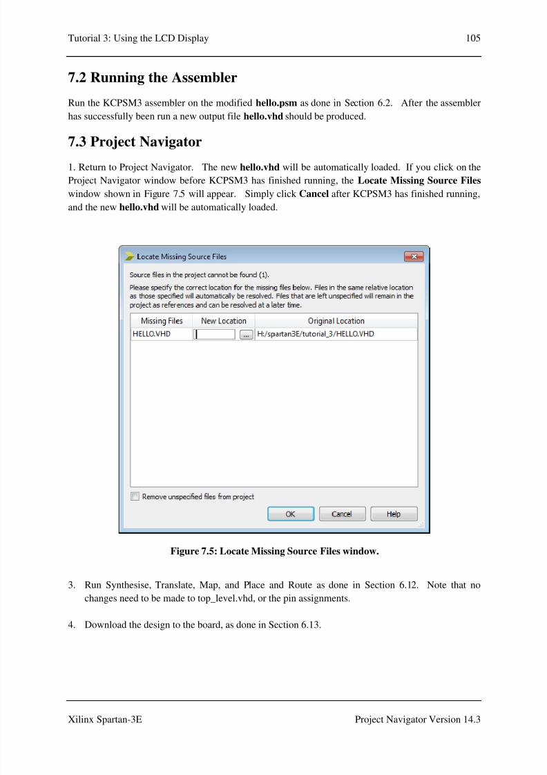
8/10/2019 Spartan3E Tutorial 3
http://slidepdf.com/reader/full/spartan3e-tutorial-3 106/162
Tutorial 3: Using the LCD Display 105
Xilinx Spartan-3E Project Navigator Version 14.3
7.2 Running the Assembler
Run the KCPSM3 assembler on the modified hello.psm as done in Section 6.2. After the assembler
has successfully been run a new output file hello.vhd should be produced.
7.3 Project Navigator
1. Return to Project Navigator. The new hello.vhd will be automatically loaded. If you click on the
Project Navigator window before KCPSM3 has finished running, the Locate Missing Source Files
window shown in Figure 7.5 will appear. Simply click Cancel after KCPSM3 has finished running,
and the new hello.vhd will be automatically loaded.
Figure 7.5: Locate Missing Source Files window.
3. Run Synthesise, Translate, Map, and Place and Route as done in Section 6.12. Note that no
changes need to be made to top_level.vhd, or the pin assignments.
4. Download the design to the board, as done in Section 6.13.

8/10/2019 Spartan3E Tutorial 3
http://slidepdf.com/reader/full/spartan3e-tutorial-3 107/162
Tutorial 3: Using the LCD Displ
Xilinx Spartan-3E
7.4 Running the Pro
The Spartan-3E board after do
displays the words “Hello Worl
Also, corresponding LEDs will
pressed.
Figure 7.6: The Sp
ay
Project N
ram on the Spartan-3E Board
wnloading the program is shown in Figure 7.
” followed by the customised characters, on the
e lit when slider switches are in the ON positio
artan-3E board with the program running for
SW38SW98SW:8SW0
106
vigator Version 14.3
. The LCD screen
first and second line.
n or push buttons are
Part B.
LD;-LD0

8/10/2019 Spartan3E Tutorial 3
http://slidepdf.com/reader/full/spartan3e-tutorial-3 108/162
Tutorial 3: Using the LCD Display 107
Xilinx Spartan-3E Project Navigator Version 14.3
8.0 Procedure Part C – Flashing and Shifting
8.1 Edit the .psm file
1. Open your file hello.psm in a text editor.
2. Place the constants shift_delay_msb and shift_delay_lsb shown in Figure 8.1, in the constants
section header of hello.psm (Block A in Figure 4.5).
Figure 8.1: Delay constants for shifting.
3. Replace the statements between cold_start: and JUMP Main in Figure 7.1 with the code of Figure
8.2.
;The main operation of the program uses 1ms delays to set the
;shift rate of the LCD display. A 16-bit value determines how
;many milliseconds there are between shifts
;
;Tests indicate that the fastest shift rate that the LCD
;display supports is 500ms. Faster than this and the display
;becomes less clear to read.
;
CONSTANT shift_delay_msb, 01 ;delay is 500ms (01F4 hex)
CONSTANT shift_delay_lsb, F4
;

8/10/2019 Spartan3E Tutorial 3
http://slidepdf.com/reader/full/spartan3e-tutorial-3 109/162
Tutorial 3: Using the LCD Display 108
Xilinx Spartan-3E Project Navigator Version 14.3
Figure 8.2: Main program loop for Part C.
3. Replace the Disp_mesg subroutine in Figure 7.2 with the code of Figure 8.3.
cold_start: CALL LCD_reset ;initialise LCD display
CALL Setup_cust_chars ;set up customised characters
CALL Disp_mesg ;display message
;
ENABLE INTERRUPT ;enable interrupts
LOAD s9, 01 ;initialise display flag to on;
Main: LOAD sF, shift_delay_msb ;[sF,sE]=loop delay in ms
LOAD sE, shift_delay_lsb
LCD_delay_loop: CALL delay_1ms ;1ms delay
SUB sE, 01 ;decrement delay counter
SUBCY sF, 00
JUMP NC, LCD_delay_loop
INPUT s7, switch_port ;read in switches
OUTPUT s7, LED_port ;output to LEDs
TEST s7, switch3 ;check for switch3 (left)
JUMP Z, Check_right
LOAD s5, 18 ;shift display left
CALL LCD_write_inst8
Check_right: TEST s7, switch2 ;check for switch2 (right)
JUMP Z, End_loop
LOAD s5, 1C ;shift display right
CALL LCD_write_inst8
End_loop: JUMP Main
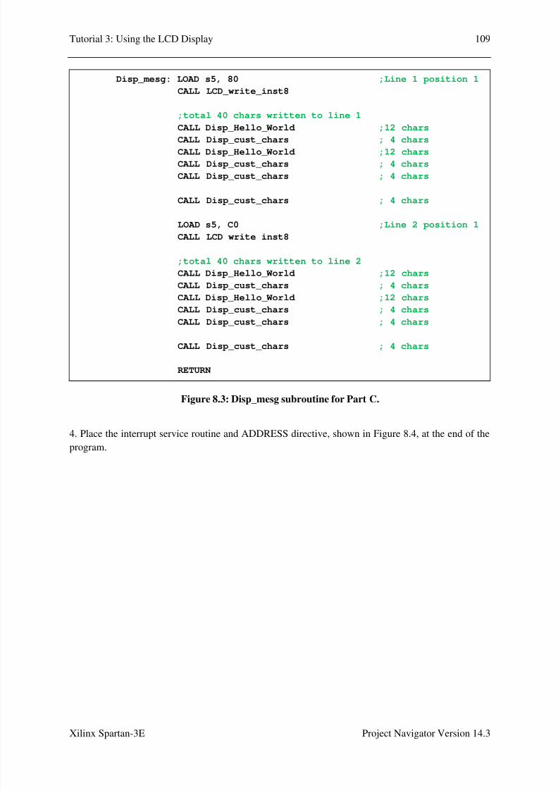
8/10/2019 Spartan3E Tutorial 3
http://slidepdf.com/reader/full/spartan3e-tutorial-3 110/162
Tutorial 3: Using the LCD Display 109
Xilinx Spartan-3E Project Navigator Version 14.3
Figure 8.3: Disp_mesg subroutine for Part C.
4. Place the interrupt service routine and ADDRESS directive, shown in Figure 8.4, at the end of the
program.
Disp_mesg: LOAD s5, 80 ;Line 1 position 1
CALL LCD_write_inst8
;total 40 chars written to line 1
CALL Disp_Hello_World ;12 chars
CALL Disp_cust_chars ; 4 chars CALL Disp_Hello_World ;12 chars
CALL Disp_cust_chars ; 4 chars
CALL Disp_cust_chars ; 4 chars
CALL Disp_cust_chars ; 4 chars
LOAD s5, C0 ;Line 2 position 1
CALL LCD_write_inst8
;total 40 chars written to line 2
CALL Disp_Hello_World ;12 chars CALL Disp_cust_chars ; 4 chars
CALL Disp_Hello_World ;12 chars
CALL Disp_cust_chars ; 4 chars
CALL Disp_cust_chars ; 4 chars
CALL Disp_cust_chars ; 4 chars
RETURN

8/10/2019 Spartan3E Tutorial 3
http://slidepdf.com/reader/full/spartan3e-tutorial-3 111/162
Tutorial 3: Using the LCD Display 110
Xilinx Spartan-3E Project Navigator Version 14.3
Figure 8.4: Interrupt service routine and ADDRESS directive.
For reference the modified hello.psm is listed in Appendix C.
The Disp_mesg subroutine in Figure 8.3 has been modified to display a longer message, which takes
up all 40 characters of both lines.
Shifting of the display is controlled by the main program loop in Figure 8.2, between the label Main:
and the instruction JUMP Main. Registers sF and sE are loaded with 0x01F4 (500 in decimal).
The code at label LCD_delay_loop: will cause the subroutine delay_1ms to be called 500 times,
creating a delay of 500ms. The switches are then read in from the switch_port. If SW3 is on, a
command is sent to the LCD to shift the display left. If SW2 is on, a command is sent to shift the
;*********************************************************
;Interrupt Service Routine
;*********************************************************
;
ISR: TEST s7, switch1 ;check for switch1 (flash)
JUMP Z, Test_disp_on;
XOR s9, 01 ;toggle display flag
TEST s9, 01 ;check if display should
;be turned on or off
JUMP NZ, Disp_on
;
LOAD s5, 08 ;turn display off
JUMP End_disp
;
Disp_on: LOAD s5, 0C ;turn display on
JUMP End_disp;
Test_disp_on: TEST s9, 01 ;if flash off, make sure
;the display is on
JUMP NZ, End_ISR
;
LOAD s9, 01 ;set display flag on
LOAD s5, 0C ;turn display on
;
End_disp: CALL LCD_write_inst8
;
End_ISR: RETURNI ENABLE
;
;---------------------------------------------------------
;
ADDRESS 3FF
JUMP ISR
;
;

8/10/2019 Spartan3E Tutorial 3
http://slidepdf.com/reader/full/spartan3e-tutorial-3 112/162

8/10/2019 Spartan3E Tutorial 3
http://slidepdf.com/reader/full/spartan3e-tutorial-3 113/162
Tutorial 3: Using the LCD Display 112
Xilinx Spartan-3E Project Navigator Version 14.3
Figure 8.6: Signals used for interrupts.
3. Add the processes of Figure 8.7, to the architecture of top_level.
-- Interrupt signals
signal count_event : std_logic;
signal count_ticks : std_logic_vector(25 downto 0) :=
"00000000000000000000000000";
-- 12.5e6 ticks = 0.25 seconds, 50MHz clock
--constant count_limit_min: std_logic_vector(25 downto 0) :=
"00110111101011110000100000";
--
-- 25e6 ticks = 0.5 seconds, 50MHz clock
constant count_limit : std_logic_vector(25 downto 0) :=
"01101111010111100001000000";
--
-- 50e6 ticks = 1 second, 50MHz clock
--constant count_limit_max: std_logic_vector(25 downto 0) :=
"10111110101111000010000000";
--
--

8/10/2019 Spartan3E Tutorial 3
http://slidepdf.com/reader/full/spartan3e-tutorial-3 114/162
Tutorial 3: Using the LCD Display 113
Xilinx Spartan-3E Project Navigator Version 14.3
Figure 8.7: Processes associated with interrupt control.
5. Run Synthesise, Translate, Map, and Place and Route as done in Section 6.12. Note that no
changes need to be made to the pin assignments.
6.
Download the design to the board, as done in Section 6.13.
For reference the modified top_level.vhd is listed in Appendix C.
Code has been added to top_level.vhd to generate interrupts to cause the display to flash at a pre-
defined time interval. The interrupt service routine code of Figure 8.4 will be called when the
interrupt signal input to the KCPSM3 becomes ‘1’. The interrupt signal is managed by the
interrupt_control process of Figure 8.7. If the count_event signal is ‘1’, the interrupt signal is set
to ‘1’. If an interrupt_ack signal comes from the KCPSM3, the interrupt signal is cancelled (set to
‘0’).
----------------------------------------------------------------------
-- interrupt
----------------------------------------------------------------------
--
-- sets an interrupt flag based on a counter
--
counter: process(clk)
begin
if clk'event and clk='1' then
count_ticks <= count_ticks + 1;
if count_ticks > count_limit then
count_event <= '1';
count_ticks <= (others => '0');
else
count_event <= '0';
end if;
end if;
end process counter;
--
----------------------------------------------------------------------
-- interrupt handler
----------------------------------------------------------------------
--
interrupt_control: process(clk)
begin
if clk'event and clk='1' then
if interrupt_ack = '1' then
interrupt <= '0';
elsif count_event = '1' then
interrupt <= '1';
else
interrupt <= interrupt;
end if;end if;
end process interrupt_control;

8/10/2019 Spartan3E Tutorial 3
http://slidepdf.com/reader/full/spartan3e-tutorial-3 115/162
Tutorial 3: Using the LCD Display 114
Xilinx Spartan-3E Project Navigator Version 14.3
Signal count_event is set by the counter process of Figure 8.7, when a counter reaches count_limit.
In Figure 8.6, count_limit has been set to a value of “01101111010111100001000000", which is the
number of clock ticks to result in a delay of 500ms, with a 50MHz clock. For experimentation
purposes, values of count_limit for delays of 250ms and 1s have been included in the code butcommented out.

8/10/2019 Spartan3E Tutorial 3
http://slidepdf.com/reader/full/spartan3e-tutorial-3 116/162
Tutorial 3: Using the LCD Displ
Xilinx Spartan-3E
8.4 Running the Pro
The Spartan-3E board after do
displays the words “Hello Worl
If slider switches SW3 or SW
respectively, with a time interva
flash, also with a time interval o
in the ON position or push butto
Figure 8.8: The Sp
ay
Project N
ram on the Spartan-3E Board
wnloading the program is shown in Figure 8.
” followed by the customised characters, on the
are in the ON position, the display will shif
l of 0.5s. If slider switch SW1 is in the ON posi
0.5s. Corresponding LEDs will also be lit wh
ns are pressed.
rtan-3E board with the program running for
SW38SW98SW:8SW
115
vigator Version 14.3
. The LCD screen
first and second line.
to the left or right
tion, the display will
n slider switches are
Part C.
LD;-LD00

8/10/2019 Spartan3E Tutorial 3
http://slidepdf.com/reader/full/spartan3e-tutorial-3 117/162
Tutorial 3: Using the LCD Display 116
Xilinx Spartan-3E Project Navigator Version 14.3

8/10/2019 Spartan3E Tutorial 3
http://slidepdf.com/reader/full/spartan3e-tutorial-3 118/162
Tutorial 3: Using the LCD Display 117
Xilinx Spartan-3E Project Navigator Version 14.3
9.0 Further Information
For further information about this tutorial, please contact:
Dr. Jasmine Banks
School of Electrical Engineering and Computer Science
Queensland University of Technology
GPO Box 2434, Brisbane 4001,
AUSTRALIA
Email: [email protected] or [email protected].

8/10/2019 Spartan3E Tutorial 3
http://slidepdf.com/reader/full/spartan3e-tutorial-3 119/162
Tutorial 3: Using the LCD Display 118
Xilinx Spartan-3E Project Navigator Version 14.3

8/10/2019 Spartan3E Tutorial 3
http://slidepdf.com/reader/full/spartan3e-tutorial-3 120/162

8/10/2019 Spartan3E Tutorial 3
http://slidepdf.com/reader/full/spartan3e-tutorial-3 121/162
Tutorial 3: Using the LCD Display 120
Xilinx Spartan-3E Project Navigator Version 14.3
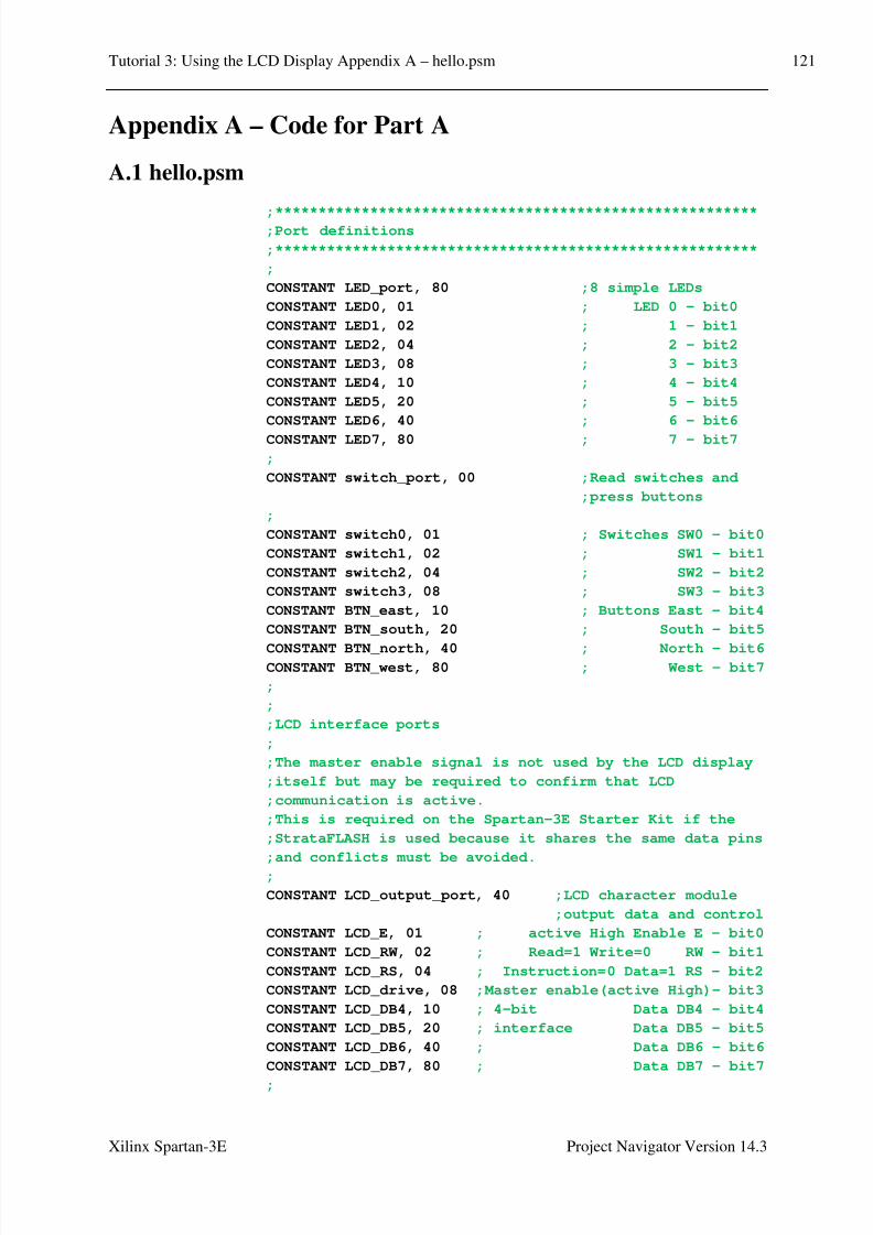
8/10/2019 Spartan3E Tutorial 3
http://slidepdf.com/reader/full/spartan3e-tutorial-3 122/162
Tutorial 3: Using the LCD Display Appendix A – hello.psm 121
Xilinx Spartan-3E Project Navigator Version 14.3
Appendix A – Code for Part A
A.1 hello.psm
;********************************************************;Port definitions
;********************************************************
;
CONSTANT LED_port, 80 ;8 simple LEDs
CONSTANT LED0, 01 ; LED 0 - bit0
CONSTANT LED1, 02 ; 1 - bit1
CONSTANT LED2, 04 ; 2 - bit2
CONSTANT LED3, 08 ; 3 - bit3
CONSTANT LED4, 10 ; 4 - bit4
CONSTANT LED5, 20 ; 5 - bit5
CONSTANT LED6, 40 ; 6 - bit6
CONSTANT LED7, 80 ; 7 - bit7
;
CONSTANT switch_port, 00 ;Read switches and
;press buttons
;
CONSTANT switch0, 01 ; Switches SW0 - bit0
CONSTANT switch1, 02 ; SW1 - bit1
CONSTANT switch2, 04 ; SW2 - bit2
CONSTANT switch3, 08 ; SW3 - bit3
CONSTANT BTN_east, 10 ; Buttons East - bit4
CONSTANT BTN_south, 20 ; South - bit5
CONSTANT BTN_north, 40 ; North - bit6CONSTANT BTN_west, 80 ; West - bit7
;
;
;LCD interface ports
;
;The master enable signal is not used by the LCD display
;itself but may be required to confirm that LCD
;communication is active.
;This is required on the Spartan-3E Starter Kit if the
;StrataFLASH is used because it shares the same data pins
;and conflicts must be avoided.
;
CONSTANT LCD_output_port, 40 ;LCD character module
;output data and control
CONSTANT LCD_E, 01 ; active High Enable E - bit0
CONSTANT LCD_RW, 02 ; Read=1 Write=0 RW - bit1
CONSTANT LCD_RS, 04 ; Instruction=0 Data=1 RS - bit2
CONSTANT LCD_drive, 08 ;Master enable(active High)- bit3
CONSTANT LCD_DB4, 10 ; 4-bit Data DB4 - bit4
CONSTANT LCD_DB5, 20 ; interface Data DB5 - bit5
CONSTANT LCD_DB6, 40 ; Data DB6 - bit6
CONSTANT LCD_DB7, 80 ; Data DB7 - bit7
;

8/10/2019 Spartan3E Tutorial 3
http://slidepdf.com/reader/full/spartan3e-tutorial-3 123/162
Tutorial 3: Using the LCD Display Appendix A – hello.psm 122
Xilinx Spartan-3E Project Navigator Version 14.3
;
CONSTANT LCD_input_port, 02 ;LCD character module
;input data
CONSTANT LCD_read_spare0, 01 ; Spare bits - bit0
CONSTANT LCD_read_spare1, 02 ; are zero - bit1
CONSTANT LCD_read_spare2, 04 ; - bit2CONSTANT LCD_read_spare3, 08 ; - bit3
CONSTANT LCD_read_DB4, 10 ; 4-bit Data DB4 - bit4
CONSTANT LCD_read_DB5, 20 ;interface Data DB5 - bit5
CONSTANT LCD_read_DB6, 40 ; Data DB6 - bit6
CONSTANT LCD_read_DB7, 80 ; Data DB7 - bit7
;
;
;Constant to define a software delay of 1us. This must be
;adjusted to reflect the clock applied to KCPSM3. Every
;instruction executes in 2 clock cycles making the
;calculation highly predictable. The '6' in the following
;equation even allows for 'CALL delay_1us' instruction in
;the initiating code.
;
;delay_1us_constant = (clock_rate - 6)/4
;Where 'clock_rate' is in MHz
;
;Example: For a 50MHz clock the constant value is
; (10-6)/4 = 11 (0B Hex).
;For clock rates below 10MHz the value of 1 must be used
;and the operation will become lower than intended.
;
CONSTANT delay_1us_constant, 0B;
;********************************************************
;Initialise the system
;********************************************************
;
cold_start: CALL LCD_reset ;initialise LCD display
CALL Disp_mesg ;display message
;
Main: INPUT s7, switch_port ;read in switches
OUTPUT s7, LED_port ;output to LEDs
JUMP Main
;
;
Disp_mesg: LOAD s5, 80 ;Line 1 position 1
CALL LCD_write_inst8
CALL Disp_Hello_World
;
LOAD s5, C0 ;Line 2 position 1
CALL LCD_write_inst8
CALL Disp_Hello_World
;
RETURN
;

8/10/2019 Spartan3E Tutorial 3
http://slidepdf.com/reader/full/spartan3e-tutorial-3 124/162
Tutorial 3: Using the LCD Display Appendix A – hello.psm 123
Xilinx Spartan-3E Project Navigator Version 14.3
Disp_Hello_World: LOAD s5, 48 ;H
CALL LCD_write_data
LOAD s5, 65 ;e
CALL LCD_write_data
LOAD s5, 6C ;l
CALL LCD_write_data;LOAD s5, 6C ;l
CALL LCD_write_data
LOAD s5, 6F ;o
CALL LCD_write_data
LOAD s5, 20 ;space
CALL LCD_write_data
LOAD s5, 57 ;W
CALL LCD_write_data
LOAD s5, 6F ;o
CALL LCD_write_data
LOAD s5, 72 ;r
CALL LCD_write_data
LOAD s5, 6C ;l
CALL LCD_write_data
LOAD s5, 64 ;d
CALL LCD_write_data
LOAD s5, 20 ;space
CALL LCD_write_data
RETURN
;
;
;********************************************************
;Software delay routines;********************************************************
;
;Delay of 1us.
;
;Constant value defines reflects the clock applied to
;KCPSM3. Every instruction executes in 2 clock cycles
;making the calculation highly predictable. The '6' in
;the following equation even allows for 'CALL delay_1us'
;instruction in the initiating code.
;
; delay_1us_constant = (clock_rate - 6)/4
; Where 'clock_rate' is in MHz
;
;Registers used s0
;
delay_1us: LOAD s0, delay_1us_constant
wait_1us: SUB s0, 01
JUMP NZ, wait_1us
RETURN
;
;Delay of 40us.
;
;Registers used s0, s1
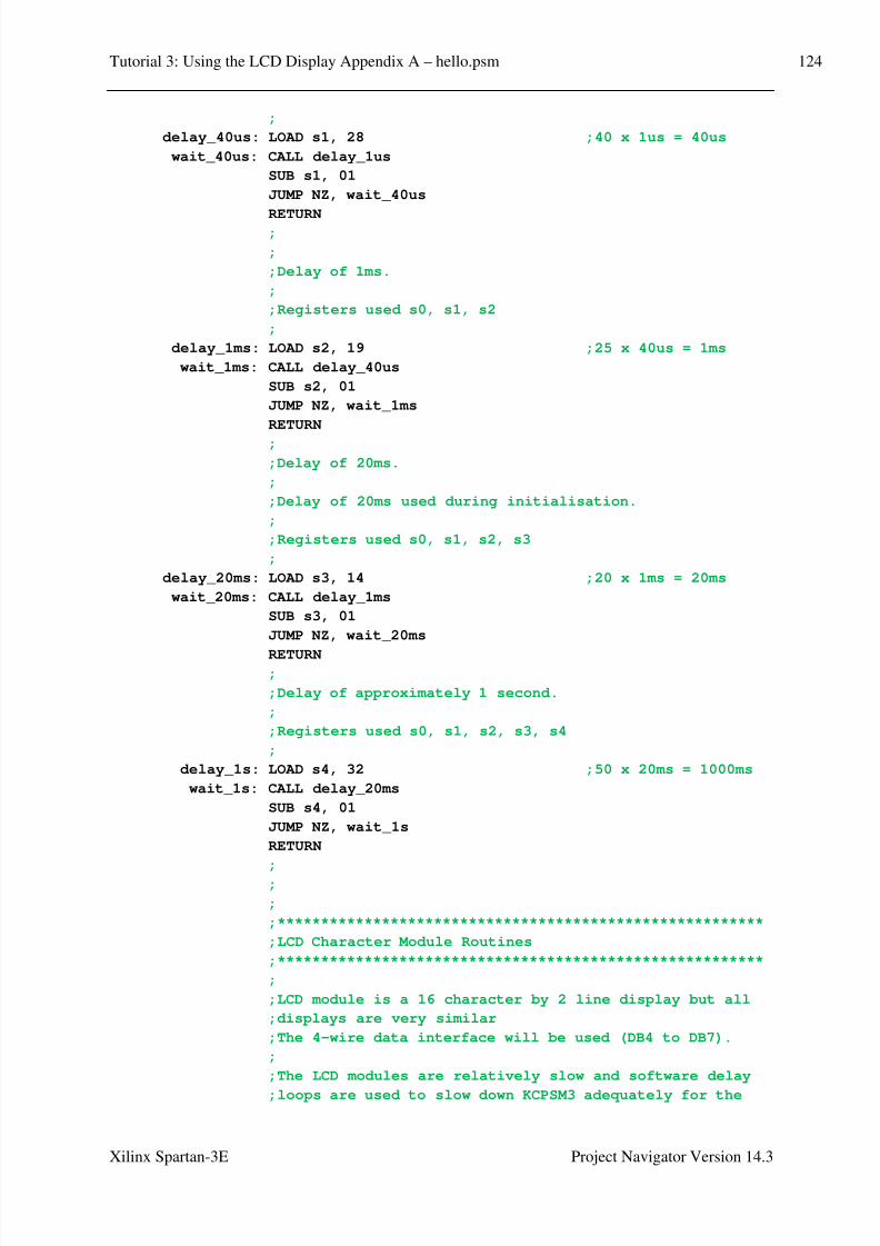
8/10/2019 Spartan3E Tutorial 3
http://slidepdf.com/reader/full/spartan3e-tutorial-3 125/162
Tutorial 3: Using the LCD Display Appendix A – hello.psm 124
Xilinx Spartan-3E Project Navigator Version 14.3
;
delay_40us: LOAD s1, 28 ;40 x 1us = 40us
wait_40us: CALL delay_1us
SUB s1, 01
JUMP NZ, wait_40us
RETURN;
;
;Delay of 1ms.
;
;Registers used s0, s1, s2
;
delay_1ms: LOAD s2, 19 ;25 x 40us = 1ms
wait_1ms: CALL delay_40us
SUB s2, 01
JUMP NZ, wait_1ms
RETURN
;
;Delay of 20ms.
;
;Delay of 20ms used during initialisation.
;
;Registers used s0, s1, s2, s3
;
delay_20ms: LOAD s3, 14 ;20 x 1ms = 20ms
wait_20ms: CALL delay_1ms
SUB s3, 01
JUMP NZ, wait_20ms
RETURN;
;Delay of approximately 1 second.
;
;Registers used s0, s1, s2, s3, s4
;
delay_1s: LOAD s4, 32 ;50 x 20ms = 1000ms
wait_1s: CALL delay_20ms
SUB s4, 01
JUMP NZ, wait_1s
RETURN
;
;
;
;********************************************************
;LCD Character Module Routines
;********************************************************
;
;LCD module is a 16 character by 2 line display but all
;displays are very similar
;The 4-wire data interface will be used (DB4 to DB7).
;
;The LCD modules are relatively slow and software delay
;loops are used to slow down KCPSM3 adequately for the
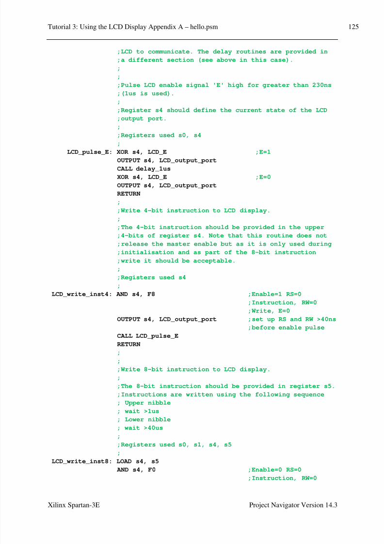
8/10/2019 Spartan3E Tutorial 3
http://slidepdf.com/reader/full/spartan3e-tutorial-3 126/162
Tutorial 3: Using the LCD Display Appendix A – hello.psm 125
Xilinx Spartan-3E Project Navigator Version 14.3
;LCD to communicate. The delay routines are provided in
;a different section (see above in this case).
;
;
;Pulse LCD enable signal 'E' high for greater than 230ns
;(1us is used).;
;Register s4 should define the current state of the LCD
;output port.
;
;Registers used s0, s4
;
LCD_pulse_E: XOR s4, LCD_E ;E=1
OUTPUT s4, LCD_output_port
CALL delay_1us
XOR s4, LCD_E ;E=0
OUTPUT s4, LCD_output_port
RETURN
;
;Write 4-bit instruction to LCD display.
;
;The 4-bit instruction should be provided in the upper
;4-bits of register s4. Note that this routine does not
;release the master enable but as it is only used during
;initialisation and as part of the 8-bit instruction
;write it should be acceptable.
;
;Registers used s4
;LCD_write_inst4: AND s4, F8 ;Enable=1 RS=0
;Instruction, RW=0
;Write, E=0
OUTPUT s4, LCD_output_port ;set up RS and RW >40ns
;before enable pulse
CALL LCD_pulse_E
RETURN
;
;
;Write 8-bit instruction to LCD display.
;
;The 8-bit instruction should be provided in register s5.
;Instructions are written using the following sequence
; Upper nibble
; wait >1us
; Lower nibble
; wait >40us
;
;Registers used s0, s1, s4, s5
;
LCD_write_inst8: LOAD s4, s5
AND s4, F0 ;Enable=0 RS=0
;Instruction, RW=0

8/10/2019 Spartan3E Tutorial 3
http://slidepdf.com/reader/full/spartan3e-tutorial-3 127/162
Tutorial 3: Using the LCD Display Appendix A – hello.psm 126
Xilinx Spartan-3E Project Navigator Version 14.3
;Write, E=0
;
OR s4, LCD_drive ;Enable=1
CALL LCD_write_inst4 ;write upper nibble
CALL delay_1us ;wait >1us
LOAD s4, s5 ;select lower nibble;with
SL1 s4 ;Enable=1
SL0 s4 ;RS=0 Instruction
SL0 s4 ;RW=0 Write
SL0 s4 ;E=0
CALL LCD_write_inst4 ;write lower nibble
CALL delay_40us ;wait >40us
LOAD s4, F0 ;Enable=0 RS=0
;Instruction, RW=0
;Write, E=0
OUTPUT s4, LCD_output_port ;Release master enable
RETURN
;
;Write 8-bit data to LCD display.
;
;The 8-bit data should be provided in register s5.
;Data bytes are written using the following sequence
; Upper nibble
; wait >1us
; Lower nibble
; wait >40us
;
;Registers used s0, s1, s4, s5;
LCD_write_data: LOAD s4, s5
AND s4, F0 ;Enable=0 RS=0
;Instruction, RW=0
;Write, E=0
;
OR s4, 0C ;Enable=1 RS=1 Data,
;RW=0 Write, E=0
;
OUTPUT s4, LCD_output_port ;set up RS and RW >40ns
;before enable pulse
;
CALL LCD_pulse_E ;write upper nibble
CALL delay_1us ;wait >1us
LOAD s4, s5 ;select lower nibble
;with
SL1 s4 ;Enable=1
SL1 s4 ;RS=1 Data
SL0 s4 ;RW=0 Write
SL0 s4 ;E=0
OUTPUT s4, LCD_output_port ;set up RS and RW >40ns
;before enable pulse
;

8/10/2019 Spartan3E Tutorial 3
http://slidepdf.com/reader/full/spartan3e-tutorial-3 128/162
Tutorial 3: Using the LCD Display Appendix A – hello.psm 127
Xilinx Spartan-3E Project Navigator Version 14.3
CALL LCD_pulse_E ;write lower nibble
CALL delay_40us ;wait >40us
LOAD s4, F0 ;Enable=0 RS=0
;Instruction, RW=0
;Write, E=0
;OUTPUT s4, LCD_output_port ;Release master enable
RETURN
;
;Read 8-bit data from LCD display.
;
;The 8-bit data will be read from the current LCD memory
;address and will be returned in register s5.
;It is advisable to set the LCD address (cursor position)
;before using the data read for the first time otherwise
;the display may generate invalid data on the first read.
;
;Data bytes are read using the following sequence
; Upper nibble
; wait >1us
; Lower nibble
; wait >40us
;
;Registers used s0, s1, s4, s5
;
LCD_read_data8: LOAD s4, 0E ;Enable=1 RS=1 Data,
;RW=1 Read, E=0
;
OUTPUT s4, LCD_output_port ;set up RS and RW >40ns;before enable pulse
;
XOR s4, LCD_E ;E=1
OUTPUT s4, LCD_output_port
CALL delay_1us ;wait >260ns to
;access data
;
INPUT s5, LCD_input_port ;read upper nibble
XOR s4, LCD_E ;E=0
OUTPUT s4, LCD_output_port
CALL delay_1us ;wait >1us
XOR s4, LCD_E ;E=1
OUTPUT s4, LCD_output_port
CALL delay_1us ;wait >260ns to
;access data
;
INPUT s0, LCD_input_port ;read lower nibble
XOR s4, LCD_E ;E=0
OUTPUT s4, LCD_output_port
AND s5, F0 ;merge upper and
;lower nibbles
SR0 s0
SR0 s0

8/10/2019 Spartan3E Tutorial 3
http://slidepdf.com/reader/full/spartan3e-tutorial-3 129/162
Tutorial 3: Using the LCD Display Appendix A – hello.psm 128
Xilinx Spartan-3E Project Navigator Version 14.3
SR0 s0
SR0 s0
OR s5, s0
LOAD s4, 04 ;Enable=0 RS=1 Data,
;RW=0 Write, E=0
;OUTPUT s4, LCD_output_port ;Stop reading 5V
;device and release
;master enable
;
CALL delay_40us ;wait >40us
RETURN
;
;Reset and initialise display to communicate using 4-bit
;data mode
;Includes routine to clear the display.
;
;Requires the 4-bit instructions 3,3,3,2 to be sent with
;suitable delays following by the 8-bit instructions to
;set up the display.
;
; 28 = '001' Function set, '0' 4-bit mode, '1' 2-line,
; '0' 5x7 dot matrix, 'xx'
; 06 = '000001' Entry mode, '1' increment, '0'
; no display shift
; 0C = '00001' Display control, '1' display on,
; '0' cursor off, '0' cursor blink off
; 01 = '00000001' Display clear
;;Registers used s0, s1, s2, s3, s4
;
LCD_reset: CALL delay_20ms ;wait more than
;15ms for display
;to be ready
;
LOAD s4, 30
CALL LCD_write_inst4 ;send '3'
CALL delay_20ms ;wait >4.1ms
CALL LCD_write_inst4 ;send '3'
CALL delay_1ms ;wait >100us
CALL LCD_write_inst4 ;send '3'
CALL delay_40us ;wait >40us
LOAD s4, 20
CALL LCD_write_inst4 ;send '2'
CALL delay_40us ;wait >40us
LOAD s5, 28 ;Function set
CALL LCD_write_inst8
LOAD s5, 06 ;Entry mode
CALL LCD_write_inst8
LOAD s5, 0C ;Display control
CALL LCD_write_inst8
LCD_clear: LOAD s5, 01 ;Display clear

8/10/2019 Spartan3E Tutorial 3
http://slidepdf.com/reader/full/spartan3e-tutorial-3 130/162
Tutorial 3: Using the LCD Display Appendix A – hello.psm 129
Xilinx Spartan-3E Project Navigator Version 14.3
CALL LCD_write_inst8
CALL delay_1ms ;wait >1.64ms for
;display to clear
CALL delay_1ms
RETURN
;

8/10/2019 Spartan3E Tutorial 3
http://slidepdf.com/reader/full/spartan3e-tutorial-3 131/162
Tutorial 3: Using the LCD Display Appendix A – top_level.vhd 130
Xilinx Spartan-3E Project Navigator Version 14.3
A.2 top_level.vhd
---------------------------------------------------------------------------
-- Company:
-- Engineer:
--
-- Create Date: 13:20:51 02/04/2013
-- Design Name:
-- Module Name: top_level - Behavioral
-- Project Name:
-- Target Devices:
-- Tool versions:
-- Description:
--
-- Dependencies:
--
-- Revision:-- Revision 0.01 - File Created
-- Additional Comments:
--
---------------------------------------------------------------------------
library IEEE;
use IEEE.STD_LOGIC_1164. ALL;
-- Uncomment the following library declaration if using
-- arithmetic functions with Signed or Unsigned values
--use IEEE.NUMERIC_STD.ALL;
-- Uncomment the following library declaration if instantiating
-- any Xilinx primitives in this code.
--library UNISIM;
--use UNISIM.VComponents.all;
entity top_level is
port ( led : out std_logic_vector (7 downto 0);
strataflash_oe : out std_logic;
strataflash_ce : out std_logic;
strataflash_we : out std_logic;
switch : in std_logic_vector (3 downto 0);
btn_north : in std_logic; btn_east : in std_logic;
btn_south : in std_logic;
btn_west : in std_logic;
lcd_d : inout std_logic_vector (7 downto 4);
lcd_rs : out std_logic;
lcd_rw : out std_logic;
lcd_e : out std_logic;
clk : in std_logic);
end top_level;
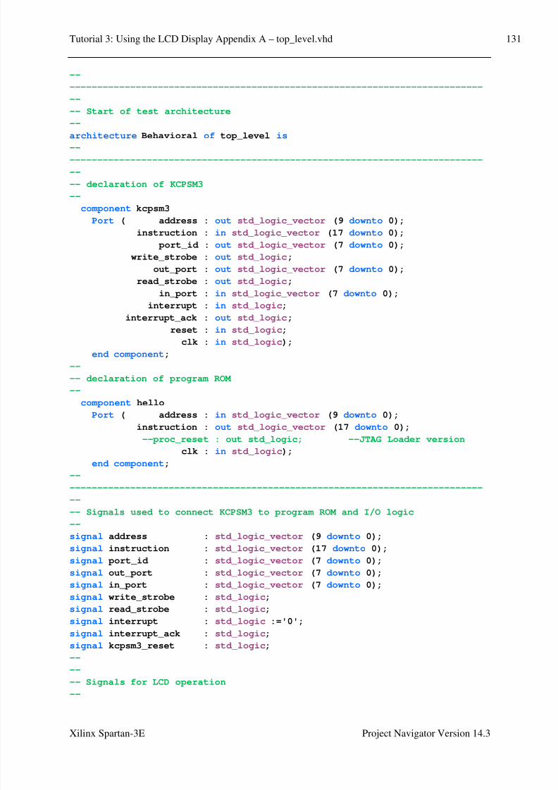
8/10/2019 Spartan3E Tutorial 3
http://slidepdf.com/reader/full/spartan3e-tutorial-3 132/162
Tutorial 3: Using the LCD Display Appendix A – top_level.vhd 131
Xilinx Spartan-3E Project Navigator Version 14.3
--
---------------------------------------------------------------------------
--
-- Start of test architecture
--
architecture Behavioral of top_level is --
---------------------------------------------------------------------------
--
-- declaration of KCPSM3
--
component kcpsm3
Port ( address : out std_logic_vector (9 downto 0);
instruction : in std_logic_vector (17 downto 0);
port_id : out std_logic_vector (7 downto 0);
write_strobe : out std_logic;
out_port : out std_logic_vector (7 downto 0);
read_strobe : out std_logic;
in_port : in std_logic_vector (7 downto 0);
interrupt : in std_logic;
interrupt_ack : out std_logic;
reset : in std_logic;
clk : in std_logic);
end component;
--
-- declaration of program ROM
--
component hello
Port ( address : in std_logic_vector (9 downto 0);instruction : out std_logic_vector (17 downto 0);
--proc_reset : out std_logic; --JTAG Loader version
clk : in std_logic);
end component;
--
---------------------------------------------------------------------------
--
-- Signals used to connect KCPSM3 to program ROM and I/O logic
--
signal address : std_logic_vector (9 downto 0);
signal instruction : std_logic_vector (17 downto 0);
signal port_id : std_logic_vector (7 downto 0);
signal out_port : std_logic_vector (7 downto 0);
signal in_port : std_logic_vector (7 downto 0);
signal write_strobe : std_logic;
signal read_strobe : std_logic;
signal interrupt : std_logic :='0';
signal interrupt_ack : std_logic;
signal kcpsm3_reset : std_logic;
--
--
-- Signals for LCD operation
--
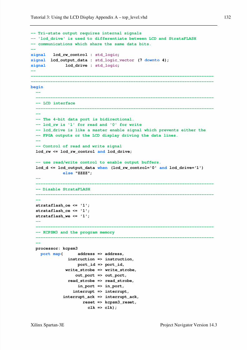
8/10/2019 Spartan3E Tutorial 3
http://slidepdf.com/reader/full/spartan3e-tutorial-3 133/162

8/10/2019 Spartan3E Tutorial 3
http://slidepdf.com/reader/full/spartan3e-tutorial-3 134/162
Tutorial 3: Using the LCD Display Appendix A – top_level.vhd 133
Xilinx Spartan-3E Project Navigator Version 14.3
program_rom: hello
port map( address => address,
instruction => instruction,
--proc_reset => kcpsm3_reset, --JTAG Loader version
clk => clk);--
-------------------------------------------------------------------------
-- KCPSM3 input ports
-------------------------------------------------------------------------
--
-- The inputs connect via a pipelined multiplexer
--
input_ports: process(clk)
begin
if clk'event and clk='1' then
case port_id(1 downto 0) is
-- read simple toggle switches and buttons at address 00 hex
when "00" => in_port <= btn_west & btn_north & btn_south
& btn_east & switch;
-- read LCD data at address 02 hex
when "10" => in_port <= lcd_d & "0000";
-- Don't care used for all other addresses to ensure
-- minimum logic implementation
when others => in_port <= "XXXXXXXX";
end case;end if;
end process input_ports;
--
-------------------------------------------------------------------------
-- KCPSM3 output ports
-------------------------------------------------------------------------
--
-- adding the output registers to the processor
--
output_ports: process(clk)
begin
if clk'event and clk='1' then
if write_strobe='1' then
-- Write to LEDs at address 80 hex.
if port_id(7)='1' then
led <= out_port;
end if;
-- LCD data output and controls at address 40 hex.
if port_id(6)='1' then
lcd_output_data <= out_port(7 downto 4);
lcd_drive <= out_port(3);

8/10/2019 Spartan3E Tutorial 3
http://slidepdf.com/reader/full/spartan3e-tutorial-3 135/162
Tutorial 3: Using the LCD Display Appendix A – top_level.vhd 134
Xilinx Spartan-3E Project Navigator Version 14.3
lcd_rs <= out_port(2);
lcd_rw_control <= out_port(1);
lcd_e <= out_port(0);
end if;
end if;
end if;end process output_ports;
end Behavioral;
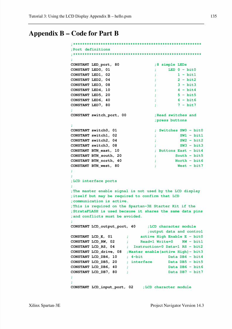
8/10/2019 Spartan3E Tutorial 3
http://slidepdf.com/reader/full/spartan3e-tutorial-3 136/162
Tutorial 3: Using the LCD Display Appendix B – hello.psm 135
Xilinx Spartan-3E Project Navigator Version 14.3
Appendix B – Code for Part B
;********************************************************
;Port definitions
;********************************************************
;
CONSTANT LED_port, 80 ;8 simple LEDs
CONSTANT LED0, 01 ; LED 0 - bit0
CONSTANT LED1, 02 ; 1 - bit1
CONSTANT LED2, 04 ; 2 - bit2
CONSTANT LED3, 08 ; 3 - bit3
CONSTANT LED4, 10 ; 4 - bit4
CONSTANT LED5, 20 ; 5 - bit5
CONSTANT LED6, 40 ; 6 - bit6
CONSTANT LED7, 80 ; 7 - bit7
;
CONSTANT switch_port, 00 ;Read switches and;press buttons
;
CONSTANT switch0, 01 ; Switches SW0 - bit0
CONSTANT switch1, 02 ; SW1 - bit1
CONSTANT switch2, 04 ; SW2 - bit2
CONSTANT switch3, 08 ; SW3 - bit3
CONSTANT BTN_east, 10 ; Buttons East - bit4
CONSTANT BTN_south, 20 ; South - bit5
CONSTANT BTN_north, 40 ; North - bit6
CONSTANT BTN_west, 80 ; West - bit7
;
;
;LCD interface ports
;
;The master enable signal is not used by the LCD display
;itself but may be required to confirm that LCD
;communication is active.
;This is required on the Spartan-3E Starter Kit if the
;StrataFLASH is used because it shares the same data pins
;and conflicts must be avoided.
;
CONSTANT LCD_output_port, 40 ;LCD character module
;output data and controlCONSTANT LCD_E, 01 ; active High Enable E - bit0
CONSTANT LCD_RW, 02 ; Read=1 Write=0 RW - bit1
CONSTANT LCD_RS, 04 ; Instruction=0 Data=1 RS - bit2
CONSTANT LCD_drive, 08 ;Master enable(active High)- bit3
CONSTANT LCD_DB4, 10 ; 4-bit Data DB4 - bit4
CONSTANT LCD_DB5, 20 ; interface Data DB5 - bit5
CONSTANT LCD_DB6, 40 ; Data DB6 - bit6
CONSTANT LCD_DB7, 80 ; Data DB7 - bit7
;
;
CONSTANT LCD_input_port, 02 ;LCD character module

8/10/2019 Spartan3E Tutorial 3
http://slidepdf.com/reader/full/spartan3e-tutorial-3 137/162
Tutorial 3: Using the LCD Display Appendix B – hello.psm 136
Xilinx Spartan-3E Project Navigator Version 14.3
;input data
CONSTANT LCD_read_spare0, 01 ; Spare bits - bit0
CONSTANT LCD_read_spare1, 02 ; are zero - bit1
CONSTANT LCD_read_spare2, 04 ; - bit2
CONSTANT LCD_read_spare3, 08 ; - bit3
CONSTANT LCD_read_DB4, 10 ; 4-bit Data DB4 - bit4CONSTANT LCD_read_DB5, 20 ;interface Data DB5 - bit5
CONSTANT LCD_read_DB6, 40 ; Data DB6 - bit6
CONSTANT LCD_read_DB7, 80 ; Data DB7 - bit7
;
;
;Constant to define a software delay of 1us. This must be
;adjusted to reflect the clock applied to KCPSM3. Every
;instruction executes in 2 clock cycles making the
;calculation highly predictable. The '6' in the following
;equation even allows for 'CALL delay_1us' instruction in
;the initiating code.
;
;delay_1us_constant = (clock_rate - 6)/4
;Where 'clock_rate' is in MHz
;
;Example: For a 50MHz clock the constant value is
; (10-6)/4 = 11 (0B Hex).
;For clock rates below 10MHz the value of 1 must be used
;and the operation will become lower than intended.
;
CONSTANT delay_1us_constant, 0B
;
;********************************************************;Initialise the system
;********************************************************
;
cold_start: CALL LCD_reset ;initialise LCD display
CALL Setup_cust_chars ;set up customised characters
CALL Disp_mesg ;display message
;
Main: INPUT s7, switch_port ;read in switches
OUTPUT s7, LED_port ;output to LEDs
JUMP Main
;
;
Disp_mesg: LOAD s5, 80 ;Line 1 position 1
CALL LCD_write_inst8
CALL Disp_Hello_World
CALL Disp_cust_chars
LOAD s5, C0 ;Line 2 position 1
CALL LCD_write_inst8
CALL Disp_Hello_World
CALL Disp_cust_chars
RETURN

8/10/2019 Spartan3E Tutorial 3
http://slidepdf.com/reader/full/spartan3e-tutorial-3 138/162
Tutorial 3: Using the LCD Display Appendix B – hello.psm 137
Xilinx Spartan-3E Project Navigator Version 14.3
;
Disp_Hello_World: LOAD s5, 48 ;H
CALL LCD_write_data
LOAD s5, 65 ;e
CALL LCD_write_data
LOAD s5, 6C ;lCALL LCD_write_data
;LOAD s5, 6C ;l
CALL LCD_write_data
LOAD s5, 6F ;o
CALL LCD_write_data
LOAD s5, 20 ;space
CALL LCD_write_data
LOAD s5, 57 ;W
CALL LCD_write_data
LOAD s5, 6F ;o
CALL LCD_write_data
LOAD s5, 72 ;r
CALL LCD_write_data
LOAD s5, 6C ;l
CALL LCD_write_data
LOAD s5, 64 ;d
CALL LCD_write_data
LOAD s5, 20 ;space
CALL LCD_write_data
RETURN
;
Disp_cust_chars: LOAD s5, 00 ;CG RAM address 00, cust char
CALL LCD_write_dataCALL LCD_write_data
LOAD s5, 01 ;CG RAM address 01, cust char
CALL LCD_write_data
LOAD s5, 20 ;space
CALL LCD_write_data
RETURN
;
Setup_cust_chars: LOAD s5, 40 ;set CG RAM address 00
CALL LCD_write_inst8
LOAD s5, 00 ;line 1
CALL LCD_write_data
LOAD s5, 0E ;line 2
CALL LCD_write_data
LOAD s5, 1F ;line 3
CALL LCD_write_data
LOAD s5, 15 ;line 4
CALL LCD_write_data
LOAD s5, 1F ;line 5
CALL LCD_write_data
LOAD s5, 1F ;line 6

8/10/2019 Spartan3E Tutorial 3
http://slidepdf.com/reader/full/spartan3e-tutorial-3 139/162
Tutorial 3: Using the LCD Display Appendix B – hello.psm 138
Xilinx Spartan-3E Project Navigator Version 14.3
CALL LCD_write_data
LOAD s5, 15 ;line 7
CALL LCD_write_data
LOAD s5, 00 ;line 8
CALL LCD_write_data
LOAD s5, 48 ;set CG RAM address 01
CALL LCD_write_inst8
LOAD s5, 0E ;line 1
CALL LCD_write_data
LOAD s5, 1F ;line 2
CALL LCD_write_data
LOAD s5, 0F ;line 3
CALL LCD_write_data
LOAD s5, 07 ;line 4
CALL LCD_write_data
LOAD s5, 0F ;line 5
CALL LCD_write_data
LOAD s5, 1F ;line 6
CALL LCD_write_data
LOAD s5, 0E ;line 7
CALL LCD_write_data
LOAD s5, 00 ;line 8
CALL LCD_write_data
RETURN
;
;
;********************************************************;Software delay routines
;********************************************************
;
;Delay of 1us.
;
;Constant value defines reflects the clock applied to
;KCPSM3. Every instruction executes in 2 clock cycles
;making the calculation highly predictable. The '6' in
;the following equation even allows for 'CALL delay_1us'
;instruction in the initiating code.
;
; delay_1us_constant = (clock_rate - 6)/4
; Where 'clock_rate' is in MHz
;
;Registers used s0
;
delay_1us: LOAD s0, delay_1us_constant
wait_1us: SUB s0, 01
JUMP NZ, wait_1us
RETURN
;
;Delay of 40us.
;

8/10/2019 Spartan3E Tutorial 3
http://slidepdf.com/reader/full/spartan3e-tutorial-3 140/162
Tutorial 3: Using the LCD Display Appendix B – hello.psm 139
Xilinx Spartan-3E Project Navigator Version 14.3
;Registers used s0, s1
;
delay_40us: LOAD s1, 28 ;40 x 1us = 40us
wait_40us: CALL delay_1us
SUB s1, 01
JUMP NZ, wait_40usRETURN
;
;
;Delay of 1ms.
;
;Registers used s0, s1, s2
;
delay_1ms: LOAD s2, 19 ;25 x 40us = 1ms
wait_1ms: CALL delay_40us
SUB s2, 01
JUMP NZ, wait_1ms
RETURN
;
;Delay of 20ms.
;
;Delay of 20ms used during initialisation.
;
;Registers used s0, s1, s2, s3
;
delay_20ms: LOAD s3, 14 ;20 x 1ms = 20ms
wait_20ms: CALL delay_1ms
SUB s3, 01
JUMP NZ, wait_20msRETURN
;
;Delay of approximately 1 second.
;
;Registers used s0, s1, s2, s3, s4
;
delay_1s: LOAD s4, 32 ;50 x 20ms = 1000ms
wait_1s: CALL delay_20ms
SUB s4, 01
JUMP NZ, wait_1s
RETURN
;
;
;
;********************************************************
;LCD Character Module Routines
;********************************************************
;
;LCD module is a 16 character by 2 line display but all
;displays are very similar
;The 4-wire data interface will be used (DB4 to DB7).
;
;The LCD modules are relatively slow and software delay

8/10/2019 Spartan3E Tutorial 3
http://slidepdf.com/reader/full/spartan3e-tutorial-3 141/162

8/10/2019 Spartan3E Tutorial 3
http://slidepdf.com/reader/full/spartan3e-tutorial-3 142/162
Tutorial 3: Using the LCD Display Appendix B – hello.psm 141
Xilinx Spartan-3E Project Navigator Version 14.3
;Instruction, RW=0
;Write, E=0
;
OR s4, LCD_drive ;Enable=1
CALL LCD_write_inst4 ;write upper nibble
CALL delay_1us ;wait >1usLOAD s4, s5 ;select lower nibble
;with
SL1 s4 ;Enable=1
SL0 s4 ;RS=0 Instruction
SL0 s4 ;RW=0 Write
SL0 s4 ;E=0
CALL LCD_write_inst4 ;write lower nibble
CALL delay_40us ;wait >40us
LOAD s4, F0 ;Enable=0 RS=0
;Instruction, RW=0
;Write, E=0
OUTPUT s4, LCD_output_port ;Release master enable
RETURN
;
;Write 8-bit data to LCD display.
;
;The 8-bit data should be provided in register s5.
;Data bytes are written using the following sequence
; Upper nibble
; wait >1us
; Lower nibble
; wait >40us
;;Registers used s0, s1, s4, s5
;
LCD_write_data: LOAD s4, s5
AND s4, F0 ;Enable=0 RS=0
;Instruction, RW=0
;Write, E=0
;
OR s4, 0C ;Enable=1 RS=1 Data,
;RW=0 Write, E=0
;
OUTPUT s4, LCD_output_port ;set up RS and RW >40ns
;before enable pulse
;
CALL LCD_pulse_E ;write upper nibble
CALL delay_1us ;wait >1us
LOAD s4, s5 ;select lower nibble
;with
SL1 s4 ;Enable=1
SL1 s4 ;RS=1 Data
SL0 s4 ;RW=0 Write
SL0 s4 ;E=0
OUTPUT s4, LCD_output_port ;set up RS and RW >40ns
;before enable pulse

8/10/2019 Spartan3E Tutorial 3
http://slidepdf.com/reader/full/spartan3e-tutorial-3 143/162
Tutorial 3: Using the LCD Display Appendix B – hello.psm 142
Xilinx Spartan-3E Project Navigator Version 14.3
;
CALL LCD_pulse_E ;write lower nibble
CALL delay_40us ;wait >40us
LOAD s4, F0 ;Enable=0 RS=0
;Instruction, RW=0
;Write, E=0;
OUTPUT s4, LCD_output_port ;Release master enable
RETURN
;
;Read 8-bit data from LCD display.
;
;The 8-bit data will be read from the current LCD memory
;address and will be returned in register s5.
;It is advisable to set the LCD address (cursor position)
;before using the data read for the first time otherwise
;the display may generate invalid data on the first read.
;
;Data bytes are read using the following sequence
; Upper nibble
; wait >1us
; Lower nibble
; wait >40us
;
;Registers used s0, s1, s4, s5
;
LCD_read_data8: LOAD s4, 0E ;Enable=1 RS=1 Data,
;RW=1 Read, E=0
;OUTPUT s4, LCD_output_port ;set up RS and RW >40ns
;before enable pulse
;
XOR s4, LCD_E ;E=1
OUTPUT s4, LCD_output_port
CALL delay_1us ;wait >260ns to
;access data
;
INPUT s5, LCD_input_port ;read upper nibble
XOR s4, LCD_E ;E=0
OUTPUT s4, LCD_output_port
CALL delay_1us ;wait >1us
XOR s4, LCD_E ;E=1
OUTPUT s4, LCD_output_port
CALL delay_1us ;wait >260ns to
;access data
;
INPUT s0, LCD_input_port ;read lower nibble
XOR s4, LCD_E ;E=0
OUTPUT s4, LCD_output_port
AND s5, F0 ;merge upper and
;lower nibbles
SR0 s0
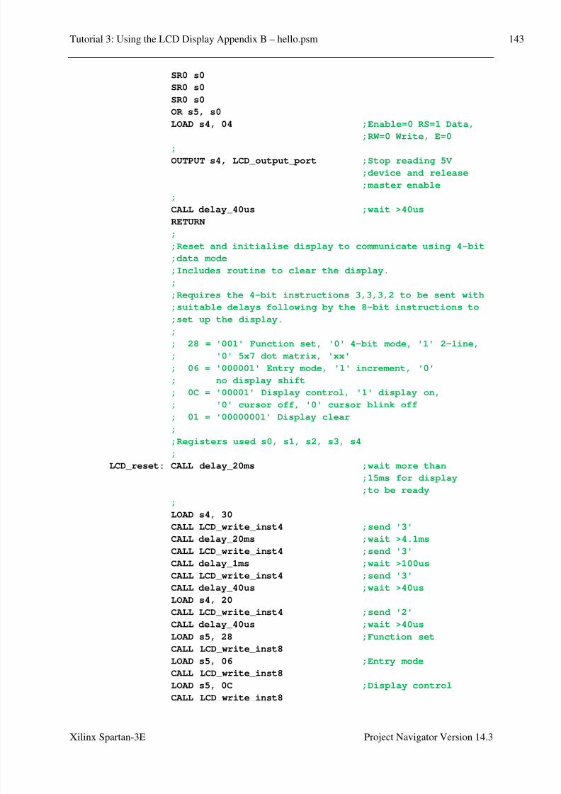
8/10/2019 Spartan3E Tutorial 3
http://slidepdf.com/reader/full/spartan3e-tutorial-3 144/162
Tutorial 3: Using the LCD Display Appendix B – hello.psm 143
Xilinx Spartan-3E Project Navigator Version 14.3
SR0 s0
SR0 s0
SR0 s0
OR s5, s0
LOAD s4, 04 ;Enable=0 RS=1 Data,
;RW=0 Write, E=0;
OUTPUT s4, LCD_output_port ;Stop reading 5V
;device and release
;master enable
;
CALL delay_40us ;wait >40us
RETURN
;
;Reset and initialise display to communicate using 4-bit
;data mode
;Includes routine to clear the display.
;
;Requires the 4-bit instructions 3,3,3,2 to be sent with
;suitable delays following by the 8-bit instructions to
;set up the display.
;
; 28 = '001' Function set, '0' 4-bit mode, '1' 2-line,
; '0' 5x7 dot matrix, 'xx'
; 06 = '000001' Entry mode, '1' increment, '0'
; no display shift
; 0C = '00001' Display control, '1' display on,
; '0' cursor off, '0' cursor blink off
; 01 = '00000001' Display clear;
;Registers used s0, s1, s2, s3, s4
;
LCD_reset: CALL delay_20ms ;wait more than
;15ms for display
;to be ready
;
LOAD s4, 30
CALL LCD_write_inst4 ;send '3'
CALL delay_20ms ;wait >4.1ms
CALL LCD_write_inst4 ;send '3'
CALL delay_1ms ;wait >100us
CALL LCD_write_inst4 ;send '3'
CALL delay_40us ;wait >40us
LOAD s4, 20
CALL LCD_write_inst4 ;send '2'
CALL delay_40us ;wait >40us
LOAD s5, 28 ;Function set
CALL LCD_write_inst8
LOAD s5, 06 ;Entry mode
CALL LCD_write_inst8
LOAD s5, 0C ;Display control
CALL LCD_write_inst8
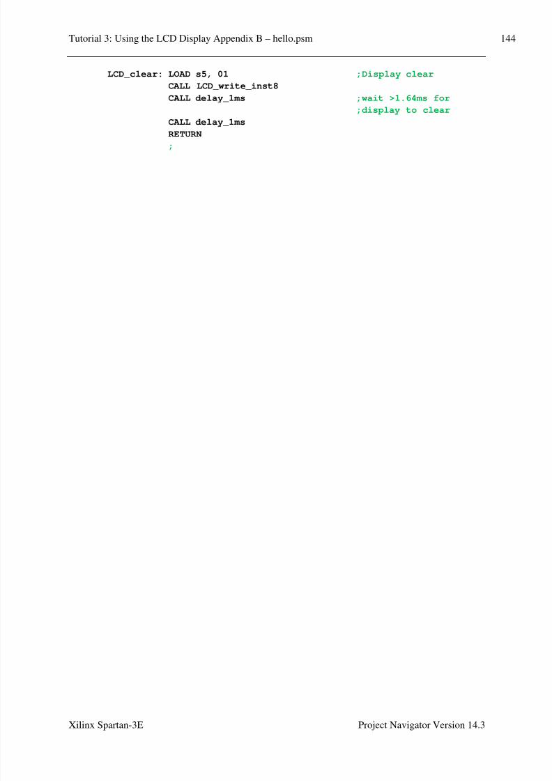
8/10/2019 Spartan3E Tutorial 3
http://slidepdf.com/reader/full/spartan3e-tutorial-3 145/162
Tutorial 3: Using the LCD Display Appendix B – hello.psm 144
Xilinx Spartan-3E Project Navigator Version 14.3
LCD_clear: LOAD s5, 01 ;Display clear
CALL LCD_write_inst8
CALL delay_1ms ;wait >1.64ms for
;display to clear
CALL delay_1ms
RETURN;

8/10/2019 Spartan3E Tutorial 3
http://slidepdf.com/reader/full/spartan3e-tutorial-3 146/162

8/10/2019 Spartan3E Tutorial 3
http://slidepdf.com/reader/full/spartan3e-tutorial-3 147/162

8/10/2019 Spartan3E Tutorial 3
http://slidepdf.com/reader/full/spartan3e-tutorial-3 148/162
Tutorial 3: Using the LCD Display Appendix C – hello.psm 147
Xilinx Spartan-3E Project Navigator Version 14.3
;
cold_start: CALL LCD_reset ;initialise LCD display
CALL Setup_cust_chars ;set up customised characters
CALL Disp_mesg ;display message
;
ENABLE INTERRUPT ;enable interrupts LOAD s9, 01 ;initialise display flag to on
;
Main: LOAD sF, shift_delay_msb ;[sF,sE]=loop delay in ms
LOAD sE, shift_delay_lsb
LCD_delay_loop: CALL delay_1ms ;1ms delay
SUB sE, 01 ;decrement delay counter
SUBCY sF, 00
JUMP NC, LCD_delay_loop
INPUT s7, switch_port ;read in switches
OUTPUT s7, LED_port ;output to LEDs
TEST s7, switch3 ;check for switch3 (left)
JUMP Z, Check_right
LOAD s5, 18 ;shift display left
CALL LCD_write_inst8
Check_right: TEST s7, switch2 ;check for switch2 (right)
JUMP Z, End_loop
LOAD s5, 1C ;shift display rightCALL LCD_write_inst8
End_loop: JUMP Main
;
;
Disp_mesg: LOAD s5, 80 ;Line 1 position 1
CALL LCD_write_inst8
;total 40 chars written to line 1
CALL Disp_Hello_World ;12 chars
CALL Disp_cust_chars ; 4 chars
CALL Disp_Hello_World ;12 chars
CALL Disp_cust_chars ; 4 chars
CALL Disp_cust_chars ; 4 chars
CALL Disp_cust_chars ; 4 chars
LOAD s5, C0 ;Line 2 position 1
CALL LCD_write_inst8
;total 40 chars written to line 2
CALL Disp_Hello_World ;12 chars
CALL Disp_cust_chars ; 4 chars

8/10/2019 Spartan3E Tutorial 3
http://slidepdf.com/reader/full/spartan3e-tutorial-3 149/162
Tutorial 3: Using the LCD Display Appendix C – hello.psm 148
Xilinx Spartan-3E Project Navigator Version 14.3
CALL Disp_Hello_World ;12 chars
CALL Disp_cust_chars ; 4 chars
CALL Disp_cust_chars ; 4 chars
CALL Disp_cust_chars ; 4 chars
RETURN
;
Disp_Hello_World: LOAD s5, 48 ;H
CALL LCD_write_data
LOAD s5, 65 ;e
CALL LCD_write_data
LOAD s5, 6C ;l
CALL LCD_write_data
;LOAD s5, 6C ;l
CALL LCD_write_data
LOAD s5, 6F ;o
CALL LCD_write_data
LOAD s5, 20 ;space
CALL LCD_write_data
LOAD s5, 57 ;W
CALL LCD_write_data
LOAD s5, 6F ;o
CALL LCD_write_data
LOAD s5, 72 ;r
CALL LCD_write_data
LOAD s5, 6C ;l
CALL LCD_write_data
LOAD s5, 64 ;dCALL LCD_write_data
LOAD s5, 20 ;space
CALL LCD_write_data
RETURN
;
Disp_cust_chars: LOAD s5, 00 ;CG RAM address 00, cust char
CALL LCD_write_data
CALL LCD_write_data
LOAD s5, 01 ;CG RAM address 01, cust char
CALL LCD_write_data
LOAD s5, 20 ;space
CALL LCD_write_data
RETURN
;
Setup_cust_chars: LOAD s5, 40 ;set CG RAM address 00
CALL LCD_write_inst8
LOAD s5, 00 ;line 1
CALL LCD_write_data
LOAD s5, 0E ;line 2
CALL LCD_write_data

8/10/2019 Spartan3E Tutorial 3
http://slidepdf.com/reader/full/spartan3e-tutorial-3 150/162
Tutorial 3: Using the LCD Display Appendix C – hello.psm 149
Xilinx Spartan-3E Project Navigator Version 14.3
LOAD s5, 1F ;line 3
CALL LCD_write_data
LOAD s5, 15 ;line 4
CALL LCD_write_data
LOAD s5, 1F ;line 5
CALL LCD_write_dataLOAD s5, 1F ;line 6
CALL LCD_write_data
LOAD s5, 15 ;line 7
CALL LCD_write_data
LOAD s5, 00 ;line 8
CALL LCD_write_data
LOAD s5, 48 ;set CG RAM address 01
CALL LCD_write_inst8
LOAD s5, 0E ;line 1
CALL LCD_write_data
LOAD s5, 1F ;line 2
CALL LCD_write_data
LOAD s5, 0F ;line 3
CALL LCD_write_data
LOAD s5, 07 ;line 4
CALL LCD_write_data
LOAD s5, 0F ;line 5
CALL LCD_write_data
LOAD s5, 1F ;line 6
CALL LCD_write_data
LOAD s5, 0E ;line 7 CALL LCD_write_data
LOAD s5, 00 ;line 8
CALL LCD_write_data
RETURN
;
;
;********************************************************
;Software delay routines
;********************************************************
;
;Delay of 1us.
;
;Constant value defines reflects the clock applied to
;KCPSM3. Every instruction executes in 2 clock cycles
;making the calculation highly predictable. The '6' in
;the following equation even allows for 'CALL delay_1us'
;instruction in the initiating code.
;
; delay_1us_constant = (clock_rate - 6)/4
; Where 'clock_rate' is in MHz
;
;Registers used s0
;

8/10/2019 Spartan3E Tutorial 3
http://slidepdf.com/reader/full/spartan3e-tutorial-3 151/162
Tutorial 3: Using the LCD Display Appendix C – hello.psm 150
Xilinx Spartan-3E Project Navigator Version 14.3
delay_1us: LOAD s0, delay_1us_constant
wait_1us: SUB s0, 01
JUMP NZ, wait_1us
RETURN
;
;Delay of 40us.;
;Registers used s0, s1
;
delay_40us: LOAD s1, 28 ;40 x 1us = 40us
wait_40us: CALL delay_1us
SUB s1, 01
JUMP NZ, wait_40us
RETURN
;
;
;Delay of 1ms.
;
;Registers used s0, s1, s2
;
delay_1ms: LOAD s2, 19 ;25 x 40us = 1ms
wait_1ms: CALL delay_40us
SUB s2, 01
JUMP NZ, wait_1ms
RETURN
;
;Delay of 20ms.
;
;Delay of 20ms used during initialisation.;
;Registers used s0, s1, s2, s3
;
delay_20ms: LOAD s3, 14 ;20 x 1ms = 20ms
wait_20ms: CALL delay_1ms
SUB s3, 01
JUMP NZ, wait_20ms
RETURN
;
;Delay of approximately 1 second.
;
;Registers used s0, s1, s2, s3, s4
;
delay_1s: LOAD s4, 32 ;50 x 20ms = 1000ms
wait_1s: CALL delay_20ms
SUB s4, 01
JUMP NZ, wait_1s
RETURN
;
;
;
;********************************************************
;LCD Character Module Routines

8/10/2019 Spartan3E Tutorial 3
http://slidepdf.com/reader/full/spartan3e-tutorial-3 152/162
Tutorial 3: Using the LCD Display Appendix C – hello.psm 151
Xilinx Spartan-3E Project Navigator Version 14.3
;********************************************************
;
;LCD module is a 16 character by 2 line display but all
;displays are very similar
;The 4-wire data interface will be used (DB4 to DB7).
;;The LCD modules are relatively slow and software delay
;loops are used to slow down KCPSM3 adequately for the
;LCD to communicate. The delay routines are provided in
;a different section (see above in this case).
;
;
;Pulse LCD enable signal 'E' high for greater than 230ns
;(1us is used).
;
;Register s4 should define the current state of the LCD
;output port.
;
;Registers used s0, s4
;
LCD_pulse_E: XOR s4, LCD_E ;E=1
OUTPUT s4, LCD_output_port
CALL delay_1us
XOR s4, LCD_E ;E=0
OUTPUT s4, LCD_output_port
RETURN
;
;Write 4-bit instruction to LCD display.
;;The 4-bit instruction should be provided in the upper
;4-bits of register s4. Note that this routine does not
;release the master enable but as it is only used during
;initialisation and as part of the 8-bit instruction
;write it should be acceptable.
;
;Registers used s4
;
LCD_write_inst4: AND s4, F8 ;Enable=1 RS=0
;Instruction, RW=0
;Write, E=0
OUTPUT s4, LCD_output_port ;set up RS and RW >40ns
;before enable pulse
CALL LCD_pulse_E
RETURN
;
;
;Write 8-bit instruction to LCD display.
;
;The 8-bit instruction should be provided in register s5.
;Instructions are written using the following sequence
; Upper nibble
; wait >1us

8/10/2019 Spartan3E Tutorial 3
http://slidepdf.com/reader/full/spartan3e-tutorial-3 153/162
Tutorial 3: Using the LCD Display Appendix C – hello.psm 152
Xilinx Spartan-3E Project Navigator Version 14.3
; Lower nibble
; wait >40us
;
;Registers used s0, s1, s4, s5
;
LCD_write_inst8: LOAD s4, s5 AND s4, F0 ;Enable=0 RS=0
;Instruction, RW=0
;Write, E=0
;
OR s4, LCD_drive ;Enable=1
CALL LCD_write_inst4 ;write upper nibble
CALL delay_1us ;wait >1us
LOAD s4, s5 ;select lower nibble
;with
SL1 s4 ;Enable=1
SL0 s4 ;RS=0 Instruction
SL0 s4 ;RW=0 Write
SL0 s4 ;E=0
CALL LCD_write_inst4 ;write lower nibble
CALL delay_40us ;wait >40us
LOAD s4, F0 ;Enable=0 RS=0
;Instruction, RW=0
;Write, E=0
OUTPUT s4, LCD_output_port ;Release master enable
RETURN
;
;Write 8-bit data to LCD display.
;;The 8-bit data should be provided in register s5.
;Data bytes are written using the following sequence
; Upper nibble
; wait >1us
; Lower nibble
; wait >40us
;
;Registers used s0, s1, s4, s5
;
LCD_write_data: LOAD s4, s5
AND s4, F0 ;Enable=0 RS=0
;Instruction, RW=0
;Write, E=0
;
OR s4, 0C ;Enable=1 RS=1 Data,
;RW=0 Write, E=0
;
OUTPUT s4, LCD_output_port ;set up RS and RW >40ns
;before enable pulse
;
CALL LCD_pulse_E ;write upper nibble
CALL delay_1us ;wait >1us
LOAD s4, s5 ;select lower nibble

8/10/2019 Spartan3E Tutorial 3
http://slidepdf.com/reader/full/spartan3e-tutorial-3 154/162
Tutorial 3: Using the LCD Display Appendix C – hello.psm 153
Xilinx Spartan-3E Project Navigator Version 14.3
;with
SL1 s4 ;Enable=1
SL1 s4 ;RS=1 Data
SL0 s4 ;RW=0 Write
SL0 s4 ;E=0
OUTPUT s4, LCD_output_port ;set up RS and RW >40ns;before enable pulse
;
CALL LCD_pulse_E ;write lower nibble
CALL delay_40us ;wait >40us
LOAD s4, F0 ;Enable=0 RS=0
;Instruction, RW=0
;Write, E=0
;
OUTPUT s4, LCD_output_port ;Release master enable
RETURN
;
;Read 8-bit data from LCD display.
;
;The 8-bit data will be read from the current LCD memory
;address and will be returned in register s5.
;It is advisable to set the LCD address (cursor position)
;before using the data read for the first time otherwise
;the display may generate invalid data on the first read.
;
;Data bytes are read using the following sequence
; Upper nibble
; wait >1us
; Lower nibble; wait >40us
;
;Registers used s0, s1, s4, s5
;
LCD_read_data8: LOAD s4, 0E ;Enable=1 RS=1 Data,
;RW=1 Read, E=0
;
OUTPUT s4, LCD_output_port ;set up RS and RW >40ns
;before enable pulse
;
XOR s4, LCD_E ;E=1
OUTPUT s4, LCD_output_port
CALL delay_1us ;wait >260ns to
;access data
;
INPUT s5, LCD_input_port ;read upper nibble
XOR s4, LCD_E ;E=0
OUTPUT s4, LCD_output_port
CALL delay_1us ;wait >1us
XOR s4, LCD_E ;E=1
OUTPUT s4, LCD_output_port
CALL delay_1us ;wait >260ns to
;access data

8/10/2019 Spartan3E Tutorial 3
http://slidepdf.com/reader/full/spartan3e-tutorial-3 155/162
Tutorial 3: Using the LCD Display Appendix C – hello.psm 154
Xilinx Spartan-3E Project Navigator Version 14.3
;
INPUT s0, LCD_input_port ;read lower nibble
XOR s4, LCD_E ;E=0
OUTPUT s4, LCD_output_port
AND s5, F0 ;merge upper and
;lower nibblesSR0 s0
SR0 s0
SR0 s0
SR0 s0
OR s5, s0
LOAD s4, 04 ;Enable=0 RS=1 Data,
;RW=0 Write, E=0
;
OUTPUT s4, LCD_output_port ;Stop reading 5V
;device and release
;master enable
;
CALL delay_40us ;wait >40us
RETURN
;
;Reset and initialise display to communicate using 4-bit
;data mode
;Includes routine to clear the display.
;
;Requires the 4-bit instructions 3,3,3,2 to be sent with
;suitable delays following by the 8-bit instructions to
;set up the display.
;; 28 = '001' Function set, '0' 4-bit mode, '1' 2-line,
; '0' 5x7 dot matrix, 'xx'
; 06 = '000001' Entry mode, '1' increment, '0'
; no display shift
; 0C = '00001' Display control, '1' display on,
; '0' cursor off, '0' cursor blink off
; 01 = '00000001' Display clear
;
;Registers used s0, s1, s2, s3, s4
;
LCD_reset: CALL delay_20ms ;wait more than
;15ms for display
;to be ready
;
LOAD s4, 30
CALL LCD_write_inst4 ;send '3'
CALL delay_20ms ;wait >4.1ms
CALL LCD_write_inst4 ;send '3'
CALL delay_1ms ;wait >100us
CALL LCD_write_inst4 ;send '3'
CALL delay_40us ;wait >40us
LOAD s4, 20
CALL LCD_write_inst4 ;send '2'
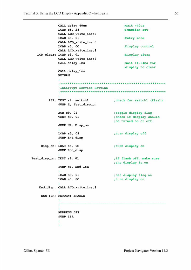
8/10/2019 Spartan3E Tutorial 3
http://slidepdf.com/reader/full/spartan3e-tutorial-3 156/162
Tutorial 3: Using the LCD Display Appendix C – hello.psm 155
Xilinx Spartan-3E Project Navigator Version 14.3
CALL delay_40us ;wait >40us
LOAD s5, 28 ;Function set
CALL LCD_write_inst8
LOAD s5, 06 ;Entry mode
CALL LCD_write_inst8
LOAD s5, 0C ;Display controlCALL LCD_write_inst8
LCD_clear: LOAD s5, 01 ;Display clear
CALL LCD_write_inst8
CALL delay_1ms ;wait >1.64ms for
;display to clear
CALL delay_1ms
RETURN
;
;********************************************************
;Interrupt Service Routine
;********************************************************
;
ISR: TEST s7, switch1 ;check for switch1 (flash)
JUMP Z, Test_disp_on
;
XOR s9, 01 ;toggle display flag
TEST s9, 01 ;check if display should
;be turned on or off
JUMP NZ, Disp_on
;
LOAD s5, 08 ;turn display off
JUMP End_disp
;Disp_on: LOAD s5, 0C ;turn display on
JUMP End_disp
;
Test_disp_on: TEST s9, 01 ;if flash off, make sure
;the display is on
JUMP NZ, End_ISR
;
LOAD s9, 01 ;set display flag on
LOAD s5, 0C ;turn display on
;
End_disp: CALL LCD_write_inst8
;
End_ISR: RETURNI ENABLE
;
;--------------------------------------------------------
;
ADDRESS 3FF
JUMP ISR
;
;
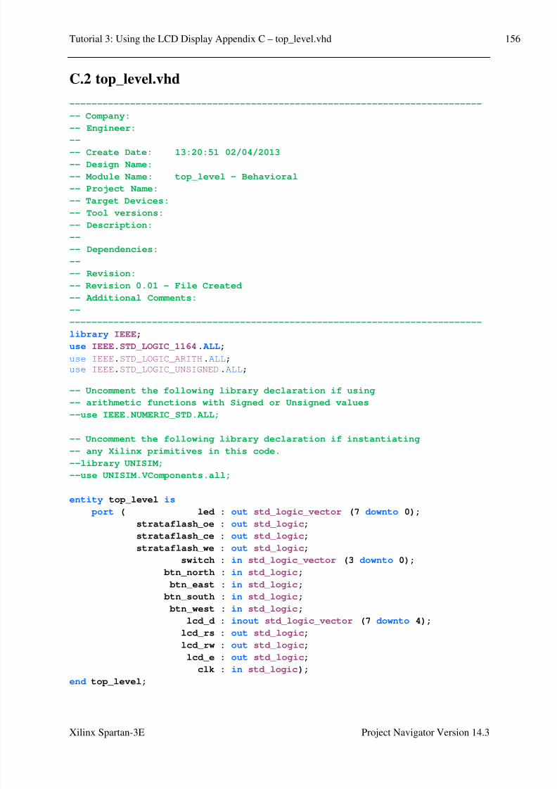
8/10/2019 Spartan3E Tutorial 3
http://slidepdf.com/reader/full/spartan3e-tutorial-3 157/162
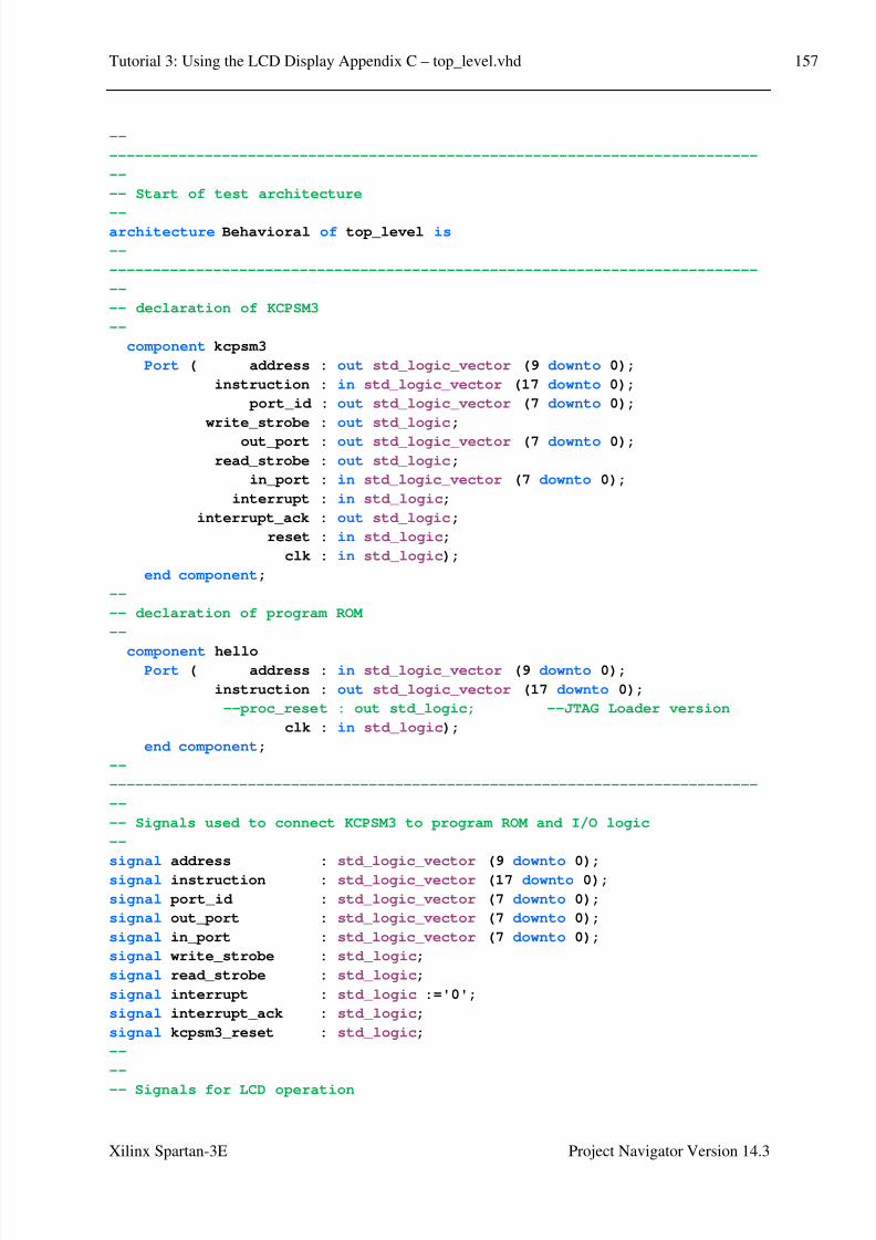
8/10/2019 Spartan3E Tutorial 3
http://slidepdf.com/reader/full/spartan3e-tutorial-3 158/162
Tutorial 3: Using the LCD Display Appendix C – top_level.vhd 157
Xilinx Spartan-3E Project Navigator Version 14.3
--
---------------------------------------------------------------------------
--
-- Start of test architecture
--architecture Behavioral of top_level is
--
---------------------------------------------------------------------------
--
-- declaration of KCPSM3
--
component kcpsm3
Port ( address : out std_logic_vector (9 downto 0);
instruction : in std_logic_vector (17 downto 0);
port_id : out std_logic_vector (7 downto 0);
write_strobe : out std_logic;
out_port : out std_logic_vector (7 downto 0);
read_strobe : out std_logic;
in_port : in std_logic_vector (7 downto 0);
interrupt : in std_logic;
interrupt_ack : out std_logic;
reset : in std_logic;
clk : in std_logic);
end component;
--
-- declaration of program ROM
--
component helloPort ( address : in std_logic_vector (9 downto 0);
instruction : out std_logic_vector (17 downto 0);
--proc_reset : out std_logic; --JTAG Loader version
clk : in std_logic);
end component;
--
---------------------------------------------------------------------------
--
-- Signals used to connect KCPSM3 to program ROM and I/O logic
--
signal address : std_logic_vector (9 downto 0);
signal instruction : std_logic_vector (17 downto 0);
signal port_id : std_logic_vector (7 downto 0);
signal out_port : std_logic_vector (7 downto 0);
signal in_port : std_logic_vector (7 downto 0);
signal write_strobe : std_logic;
signal read_strobe : std_logic;
signal interrupt : std_logic :='0';
signal interrupt_ack : std_logic;
signal kcpsm3_reset : std_logic;
--
--
-- Signals for LCD operation

8/10/2019 Spartan3E Tutorial 3
http://slidepdf.com/reader/full/spartan3e-tutorial-3 159/162
Tutorial 3: Using the LCD Display Appendix C – top_level.vhd 158
Xilinx Spartan-3E Project Navigator Version 14.3
--
-- Tri-state output requires internal signals
-- 'lcd_drive' is used to differentiate between LCD and StrataFLASH
-- communications which share the same data bits.
--
signal lcd_rw_control : std_logic;signal lcd_output_data : std_logic_vector (7 downto 4);
signal lcd_drive : std_logic;
--
-- Interrupt signals
signal count_event : std_logic;
signal count_ticks : std_logic_vector(25 downto 0) :=
"00000000000000000000000000";
-- 12.5e6 ticks = 0.25 seconds, 50MHz clock
--constant count_limit_min: std_logic_vector(25 downto 0) :=
"00110111101011110000100000";
--
-- 25e6 ticks = 0.5 seconds, 50MHz clock
constant count_limit : std_logic_vector(25 downto 0) :=
"01101111010111100001000000";
--
-- 50e6 ticks = 1 second, 50MHz clock
--constant count_limit_max: std_logic_vector(25 downto 0) :=
"10111110101111000010000000";
--
--
---------------------------------------------------------------------------
---------------------------------------------------------------------------
begin
---------------------------------------------------------------------------
-- LCD interface
-------------------------------------------------------------------------
--
-- The 4-bit data port is bidirectional.
-- lcd_rw is '1' for read and '0' for write
-- lcd_drive is like a master enable signal which prevents either the
-- FPGA outputs or the LCD display driving the data lines.
--
-- Control of read and write signal
lcd_rw <= lcd_rw_control and lcd_drive;
-- use read/write control to enable output buffers.
lcd_d <= lcd_output_data when (lcd_rw_control='0' and lcd_drive='1')
else "ZZZZ";
--
-------------------------------------------------------------------------
-- Disable StrataFLASH
-------------------------------------------------------------------------
--
strataflash_oe <= '1';
strataflash_ce <= '1';
strataflash_we <= '1';

8/10/2019 Spartan3E Tutorial 3
http://slidepdf.com/reader/full/spartan3e-tutorial-3 160/162
Tutorial 3: Using the LCD Display Appendix C – top_level.vhd 159
Xilinx Spartan-3E Project Navigator Version 14.3
--
-------------------------------------------------------------------------
-- KCPSM3 and the program memory
-------------------------------------------------------------------------
--
processor: kcpsm3 port map( address => address,
instruction => instruction,
port_id => port_id,
write_strobe => write_strobe,
out_port => out_port,
read_strobe => read_strobe,
in_port => in_port,
interrupt => interrupt,
interrupt_ack => interrupt_ack,
reset => kcpsm3_reset,
clk => clk);
program_rom: hello
port map( address => address,
instruction => instruction,
--proc_reset => kcpsm3_reset, --JTAG Loader version
clk => clk);
--
-------------------------------------------------------------------------
-- KCPSM3 input ports
-------------------------------------------------------------------------
--
-- The inputs connect via a pipelined multiplexer--
input_ports: process(clk)
begin
if clk'event and clk='1' then
case port_id(1 downto 0) is
-- read simple toggle switches and buttons at address 00 hex
when "00" => in_port <= btn_west & btn_north & btn_south
& btn_east & switch;
-- read LCD data at address 02 hex
when "10" => in_port <= lcd_d & "0000";
-- Don't care used for all other addresses to ensure
-- minimum logic implementation
when others => in_port <= "XXXXXXXX";
end case;
end if;
end process input_ports;
--
-------------------------------------------------------------------------
-- KCPSM3 output ports
-------------------------------------------------------------------------

8/10/2019 Spartan3E Tutorial 3
http://slidepdf.com/reader/full/spartan3e-tutorial-3 161/162
Tutorial 3: Using the LCD Display Appendix C – top_level.vhd 160
Xilinx Spartan-3E Project Navigator Version 14.3
--
-- adding the output registers to the processor
--
output_ports: process(clk)
begin
if clk'event and clk='1' then if write_strobe='1' then
-- Write to LEDs at address 80 hex.
if port_id(7)='1' then
led <= out_port;
end if;
-- LCD data output and controls at address 40 hex.
if port_id(6)='1' then
lcd_output_data <= out_port(7 downto 4);
lcd_drive <= out_port(3);
lcd_rs <= out_port(2);
lcd_rw_control <= out_port(1);
lcd_e <= out_port(0);
end if;
end if;
end if;
end process output_ports;
--
-------------------------------------------------------------------------
-- interrupt
-------------------------------------------------------------------------
---- sets an interrupt flag based on a counter
--
counter: process(clk)
begin
if clk'event and clk='1' then
count_ticks <= count_ticks + 1;
if count_ticks > count_limit then
count_event <= '1';
count_ticks <= (others => '0');
else
count_event <= '0';
end if;
end if;
end process counter;
--
-------------------------------------------------------------------------
-- interrupt handler
-------------------------------------------------------------------------
--
interrupt_control: process(clk)
begin
if clk'event and clk='1' then
if interrupt_ack = '1' then

8/10/2019 Spartan3E Tutorial 3
http://slidepdf.com/reader/full/spartan3e-tutorial-3 162/162
Tutorial 3: Using the LCD Display Appendix C – top_level.vhd 161
interrupt <= '0';
elsif count_event = '1' then
interrupt <= '1';
else
interrupt <= interrupt;
end if;end if;
end process interrupt_control;
end Behavioral;