Embed Size (px)
Citation preview

1
Asynchronous Massive Access and NeighborDiscovery Using OFDMA
Xu Chen∗, Lina Liu†, Dongning Guo†, Gregory W. Wornell‡∗ Waymo, Mountain View, CA
†Department of Electrical and Computer Engineering, Northwestern University, Evanston, IL‡Department of Electrical Engineering and Computer Science, Massachusetts Institute of Technology,
Cambridge, MA
Abstract
The fundamental communication problem in the wireless Internet of Things (IoT) is to discover a massive numberof devices and to allow them reliable access to shared channels. Oftentimes these devices transmit short messagesrandomly and sporadically. This paper proposes a novel signaling scheme for grant-free massive access, where eachdevice encodes its identity and/or information in a sparse set of tones. Such transmissions are implemented in theform of orthogonal frequency-division multiple access (OFDMA). Under some mild conditions and assuming devicedelays to be bounded unknown multiples of symbol intervals, sparse OFDMA is proved to enable arbitrarily reliableasynchronous device identification and message decoding with a codelength that is O(K(logK + logS + logN)),where N denotes the device population, K denotes the actual number of active devices, and logS is essentially equalto the number of bits a device can send (including its identity). By exploiting the Fast Fourier Transform (FFT), thecomputational complexity for discovery and decoding can be made to be sub-linear in the total device population.To prove the concept, a specific design is proposed to identify up to 100 active devices out of 238 possible deviceswith up to 20 symbols of delay and moderate signal-to-noise ratios and fading. The codelength compares much morefavorably with those of standard slotted ALOHA and carrier-sensing multiple access (CSMA) schemes.
I. INTRODUCTION
By some estimate [1], there will be up to 500 billion connected devices world-wide in the Internet of Things (IoT)by year 2030. There can be well over a million low-cost, battery-powered IoT devices within 500 meter range in adensely populated area. The general term of massive access describes the setting where a large number of devicesneed to access a shared medium in the uplink to send messages to some access points. Usually, wireless IoT devicestransmit short messages randomly and sporadically. If the access points only need to decode the messages but arenot interested in the corresponding devices’ identities, the setting is referred to as unsourced random access [2]. Inthe other extreme where the sole purpose is to detect and identify active devices within range, the setting is oftenreferred to as neighbor discovery or device identification. Whereas neighbor discovery is a special case of massiveaccess, the latter can also be regarded as the former if the transmitted data are regarded as all or a segment of thedevice identities.
Most IoT access solutions in practice either orthogonalize transmissions or suffer from collisions over the air.In particular, using a naive time division multiple access (TDMA) scheme to schedule densely deployed deviceswould incur large latencies. So would a random access mechanism based on classical ALOHA. Since the number ofdevices far exceeds the frame length, it is also impossible to assign nearly orthogonal sequences to all the devicesto support code division multiple access (CDMA), especially due to device asynchrony. Moreover, massive accessusing conventional multiuser detection approaches generally involves a polynomial complexity in the number ofdevices [3], which is also unaffordable.
In practice, it is hard to eliminate relative delays between devices, in part because of their different distancesto the same access point. For example, a difference of 300 meters implies a free space propagation delay of onemicrosecond, which spans 20 samples at 20 million samples per second. On the other hand, the maximum relativedelay can be within a small fraction of a frame if a common timing reference such as a beacon signal is available.
A successful massive access solution for the IoT should be ultra-scalable to support a massive number of devices,incur low latencies, and allow for some asynchrony between devices.
A. Related Work
To detect and/or decode messages from many transmitters sharing a common medium is a problem in the wellestablished area of multiuser detection. A small-scale neighbor discovery problem is studied as a multiuser detection
arX
iv:1
706.
0938
7v2
[cs
.IT
] 1
9 N
ov 2
021

2
problem in [3]. In a more challenging case where the device population is several orders of magnitude larger thanthe number of active devices, schemes inspired by the compressed sensing (CS) literature are proposed in [4]–[12].These schemes can reduce the codelength substantially when compared with 802.11 type protocols, but most ofthose schemes require synchronous transmissions. A convex optimization based algorithm is proposed to detectactive devices using asynchronous CDMA random access [13], but the polynomial complexity in [4]–[13] scalespoorly for massive access.
Non-orthogonal multiple access (NOMA) allows multiple devices to share the time and frequency resources viapower domain or code domain multiplexing [14], [15], where successive interference cancellation (SIC) is usedto cancel multiuser interference at the receiver. NOMA’s decoding algorithms (e.g., message passing [16]) havein general polynomial complexities in the device population. However, whether NOMA is resilient to imperfectchannel state information is not well understood.
The information-theoretic limits of uplink and downlink massive access are studied in [17] and [18], respectively,where the number of devices scales with the codelength in general. It is shown therein that separate deviceidentification and message decoding is capacity-achieving. The degree of freedom of massive access fading channelsis analyzed in [19]. The capacity of asynchronous massive access is analyzed in [20]. SIC does not achieve theboundary of the capacity region in the case of asynchronous NOMA [21]. An alternative information-theoreticalmodel is proposed in [2], where the access point aims to decode the set of messages regardless of the correspondingsources. Low-complexity schemes have been proposed for unsourced multiple access [22]–[25]. Reference [22]proposes T -fold ALOHA. Reference [23] uses CS for sub-block recovery and a tree-based algorithm for sub-blockstitching. A sparse regression code is used in [24] as an inner code with a corresponding approximate messagepassing based algorithm as a inner decoder. Binary chirp coding and chirp reconstruction algorithm is studied in[25]. These schemes require fully synchronous transmissions.
The idea of codes on graph has also been applied in random access [26], [27]. One notable scheme is codedslotted ALOHA, in which packets are repeatedly transmitted in different slots and are decoded using successivecancellation under the assumptions of synchronous transmissions and perfect cancellation. The asynchronous modelis studied in [28]–[30] under the idealized assumption of perfect cancellation. Rateless codes have been proposedfor multiple access in machine-to-machine communications [31], where the channel gains are assumed to be known.As the number of users increases, the imperfect channel estimation is detrimental to the performance of successivecancellation.
B. ContributionsThe goal here is to develop a suitable signaling scheme for grant-free transmissions by a large number of devices
with moderate delay uncertanties. The specific contributions of this paper are summarized as follows:1) We propose a novel scheme, referred to as sparse OFDMA, where a device encodes its information and/or
identity onto a sparse set of orthogonal tones. We exploit the fact that the tones’ frequencies are invariant todelays. Sparse OFDMA is highly effective in an asynchronous setting, which is particularly appealing in thecontext of the IoT.
2) The proposed scheme utilizes low-complexity point-to-point capacity-approaching codes and exploits multiuserdiversity using successive cancellation.
3) In the asymptotic regime where the number of active devices and the maximum delay are sublinear relativeto the device population, sparse OFDMA correctly detect all active devices with high probability, usingan essentially sublinear codelength in the device population. With a bounded maximum delay, under mildconditions for the number of active devices, the computational complexity is also sublinear in the devicepopulation (due to a sparse Fourier transform).
C. Paper Organization and NotationsThe rest of the paper is organized as follows. Section II presents the system model and main results. Section III
describes the signalling scheme of sparse OFDMA. Section IV presents the asynchronous massive access algorithm.Section V and Section VI prove theoretical performance guarantees for synchronous and asynchronous transmissions,respectively. Section VII presents some numerical results on a practical design. Section VIII concludes the paper.
For ease of notation, the index of a vector or each dimension of a matrix starts from 0 throughout the paper. Theelements of a B × C matrix are denoted as ycb , where c = 0, · · · , C − 1 and b = 0, · · · , B − 1. We write the b-throw vector as yb =
(y0b , · · · , yC−1
b
)and the c-th column vector as yc =
(yc0, · · · , ycB−1
)T. We denote the real and
imaginary parts of a variable X as XR and XI , respectively. All logarithms are base 2.
3
0 m0 m1 m2
s0
s1
s2
Fig. 1: Frame-asynchronous symbol-synchronous three-user model.
II. SYSTEM MODEL AND MAIN RESULTS
We focus on the uplink access problem in a system consisting of one access point and N potential devices intotal. Let {0, · · · , N−1} denote the set of device indices. An arbitrary subset of devices are within the range of theaccess point and active, whose indices form the set K ⊆ {0, · · · , N −1}. Let K = |K| denote the number of activedevices. For tractability, we assume symbol synchrony without frame synchrony, i.e., the delay of each device’ssignal at the access point is an integer number of symbol intervals. We further assume the delays are similar. Thiscan be accomplished by using a common beacon to trigger transmissions. Specifically, let the delay of any devicerelative to a reference at the access point be no more than M symbol intervals. Fig. 1 illustrates a small examplewith three devices.
Let sk = (sk,0, . . . , sk,L−1) denote the L-symbol codeword transmitted by device k. In the absence of frequencyselectivity, the received signal at every (integer) time i is given by
xi =∑
k∈Kaksk,i−mk + wi, (1)
where ak ∈ C is the channel coefficient, mk is the transmission delay of device k, and wi ∼ CN (0, 2σ2) areindependently and identically distributed (i.i.d.) circularly symmetric complex Gaussian random variables. Thediscovery scheme is based on signals within a single codeword duration. From each receiver’s point of view, thesignal sk,i = 0 for i < 0 and i ≥ L for all k.
We shall design a massive access scheme with relatively small codelength and low computational complexity.The following two theorems are our key results for the synchronous case and the asynchronous case, respectively:
Theorem 1: Suppose each device’s message set contains no more than S messages. Suppose, out of N devices, anunknown subset of devices transmit. Suppose their signals are perfectly aligned at the receiver, so that the maximumdelay M = 0. Suppose also the noise variance is fixed and the received signal amplitude of every active device is atleast a. Then for every a, ε > 0, there exist α0, α1,K0 > 0 such that for every N and K satisfying N ≥ K ≥ K0,there exists a code of length
L ≤ α0K(logN + logS + logK) (2)
such that as long as no more than K devices transmit, all their identities and messages will be decoded correctlywith probability no less than 1 − ε. Moreover, this can be accomplished using fewer than α1K(logK)(logN +logS + logK) arithmetic operations.
Theorem 2: Suppose each device’s message set contains no more than S messages. Suppose, out of N devices,an unknown subset of devices transmit. Suppose the delay of every active device is an integer number of symbolintervals less than M ≥ 0. Suppose also the noise variance is fixed and the received signal amplitude of everyactive device is bounded between a and a. Then for every a, a, ε > 0 with a ≤ a, there exist α0, α1,K0 > 0 suchthat for every N and K satisfying N ≥ K ≥ K0, there exists a code of length
L ≤ α0 ((K +M)(logN + logS + logK) +K log(M + 1)) (3)
such that as long as no more than K devices transmit, all their identities and messages will be decoded correctlywith probability no less than 1 − ε. Moreover, this can be accomplished using fewer than α1(K(logK)(logN +logS + logK) +KM2 +K2M log(KM + 1)) arithmetic operations.
Theorems 1 and 2 provide a scaling law for the complexity and codelength in terms of the device population,the number of active devices, and the delay bound. Synchronous massive access, i.e., M = 0, requires a smallercodelength and fewer arithmetic operations than the asynchronous case. Theorem 2 reduces to Theorem 1 in thespectial case of M = 0.

4
With fixed maximum delay M , when the codebook size S = O(N) and the number of active users K satisfiesK logK = o(N), the codelengths for both the synchronous and asynchronous schemes are sublinear in the devicepopulation N according to Theorems 1 and 2. Furthermore, with fixed M , if K2 logK = o(N), the number ofarithmetic operations involved in the asynchronous scheme is also sublinear in N .
III. SPARSE OFDMA SIGNALING
In this section, we propose a specific signaling scheme. Let the spectrum be divided into B orthogonal subcarriers,where B is much smaller than the device population N . It is not possible to design mutually orthogonal OFDMsymbols for all N devices. We let each active device transmit several OFDM symbols on a sparse subset of thesubcarriers. The scheme is thus referred to as sparse OFDMA. We shall show that sparse OFDMA of moderatesymbol duration can accomodate a large number of devices with bursty transmissions.
We develop sparse OFDMA in four steps. First, we consider noiseless device identification with fewer devicesthan the number of subcarriers (N ≤ B). Second, we consider noiseless device identification where N > B anda single device is active. Third, we consider the general noisy device identification, where N > B and K � Ndevices are active. At last, we consider simultaneous device identification and message decoding.
A. Noiseless Device Identification with N ≤ BThe key idea for addressing arbitrary delays is to use the fact that the frequency of a sinusoidal signal is invariant
to delay, where the delay merely causes a phase shift. Since the delay is bounded by M , we include M samples inthe OFDM symbol as a cyclic prefix. Hence, each OFDM symbol contains B +M samples. Since N ≤ B, devicek can be assigned the unique subcarrier k. The transmitted discrete-time signal structure is given by
sk,i = gk exp
(ι2πki
B
), i = 0, · · · , B +M − 1, (4)
where gk ∈ R is a known design parameter of unit amplitude and ι2 = −1.At the receiver side, the signals from all the neighbors arrive after a reference frame start point. The receiver
discards the first M samples of each sparse OFDMA symbol and collect the next B samples as y = (y0, · · · , yB−1),where yi = xi+M , i = 0, · · · , B − 1. If each device is assigned a unique subcarrier, performing B-point discreteFourier transform (DFT) on y yields nonzero at the k-th subcarrier if and only if device k is active. The delaymk only affects the phase of the DFT value. Therefore, the signaling scheme (4) is sufficient to detect the activedevices in a noiseless case with computational complexity of O(B logB) needed by the Fast Fourier Transform(FFT) algorithm.
B. Noiseless Single Device Identification with N > B
With N > B, it is impossible to assign a distinct subcarrier to each device. Suppose we randomly assign subcarrierbk ∈ {0, · · · , B − 1} to device k and still apply the signaling scheme give by (4). If performing B-point DFT ony yields nonzero at subcarrier b, we cannot be sure about which device is active if multiple devices are assignedto this subcarrier. We resolve this ambiguity by including several OFDM symbols in a frame and embedding thedevice’s identity through coefficient gk in (4) across the OFDM symbols for transmission.
Let J = dlogNe and let (k)2 = (k1, · · · , kJ) denote the binary representation of device index k. We simplyadopt the design of
(g0k, · · · , gJk
)=(1, (−1)k1 , · · · , (−1)kJ
). We let device k transmit
(s0k, · · · , sJk
), where sjk =
(sjk,0, · · · , sjk,B+M−1) and
sjk,i = gjk exp
(ι2πbki
B
), (5)
for i = 0, · · · , B+M −1 and j = 0, · · · , J . The code length is thus (J+1)(B+M) samples. For the j-th OFDMsymbol, we discard the first M samples and use the next B samples to form a vector yj = (yj0, · · · , yjB−1), where
yji = xi+j(B+M)+M (6)
= aksjk,i+M−mk , (7)

5
Subcarrier 0
Subcarrier 1
Subcarrier 2
Subcarrier 3
Subcarrier 4
Device 0
Device 1
Device 2
Device 3
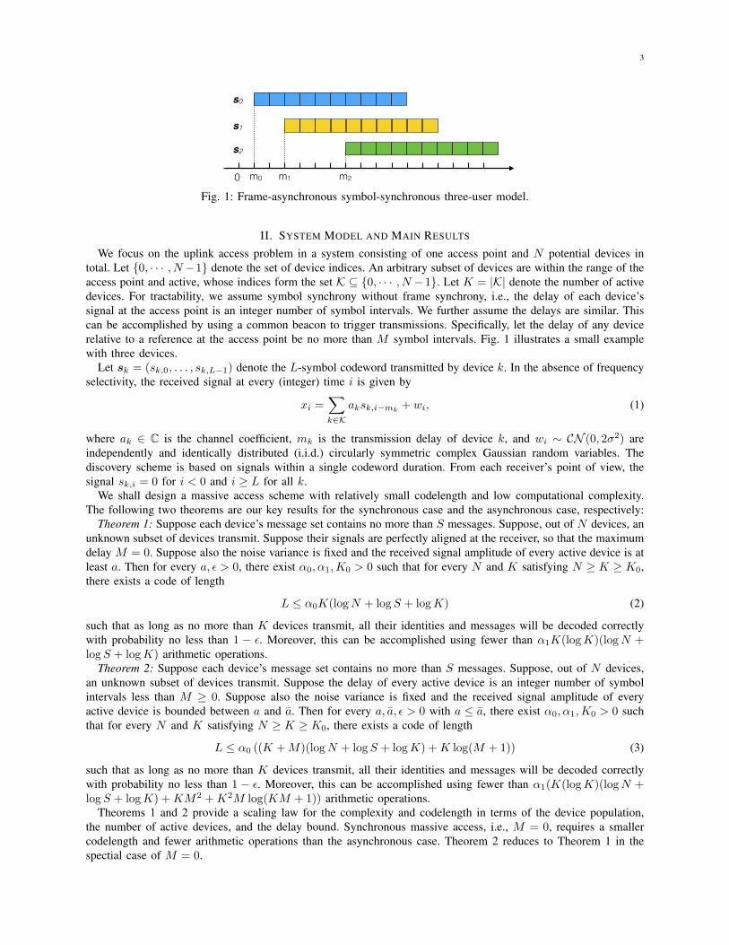
Fig. 2: Bipartite graph representation of sparse OFDMA. Left nodes represent devices and right nodes representsubcarriers. The active devices are marked in red. Subcarriers 0, 1 and 4 are zerotons, subcarrier 3 is a singleton,and subcarrier 2 is a multiton.
i = 0, · · · , B − 1. Performing B-point DFT on yj yields
Y jb =1
B
B−1∑
i=0
exp
(− ι2πbi
B
)aks
jk,i+M−mk (8)
=
{0, if b 6= bk
Ak,bgjk, if b = bk,
(9)
whereAk,b = ak exp
(ι2πbk(M −mk)
B
). (10)
As in the B ≥ N case, the delay mk only affects the phase of the received signal from device k.Subcarrier b is associated with a length-(J + 1) vector Y b = (Y 0
b , · · · , Y Jb ). It can be seen that g0k serves as a
reference symbol capturing the channel coefficients. In our setting, Y 0b = Ak,b. Therefore, the j-th bit of the binary
representation of k can be estimated as kj = 0 if Y jb /Y0b = 1 and kj = 1 if Y jb /Y
0b = −1.
Together, bk (frequency) and g0k, . . . , g
Jk (gains) carry the device index. The correspondence between the device
indices and the subcarriers is represented by a bipartite graph with N left nodes and B right nodes. The n-th leftnode is connected with the b-th right node if device n transmits on the b-th subcarrier.
Definition 1: [Bipartite graph induced by active devices in the sparse OFDMA] The bipartite graph induced bythe active devices in sparse OFDMA consists of K left nodes, corresponding to K active devices, and B rightnodes, corresponding to B subcarriers, where the k-th left node is connected to the b-th right node if device ktransmits on subcarrier b.
We call a subcarrier a zeroton, singleton, or multiton, if no device, a single device, or multiple devices transmiton the subcarrier, respectively. Fig. 2 illustrates an example of bipartite graph with B = 5 subcarriers and N = 4devices, K = 3 of which are active. In the example, subcarriers 0, 1, and 4 are zerotons, subcarrier 3 is a singleton,and subcarrier 2 is a multiton.
When there is a single active device in the noiseless setting, the signaling of sparse OFDMA consists of dlogNeOFDM symbols. Therefore, the active device can be identified with code length of O((B+M) logN) samples andcomputational complexity of O(B(logB)(logN)).
C. Identification of Multiple Active Devices With and Without Noise
When multiple devices are active, the active devices may use colliding subcarriers, so that the device informationcannot always be directly recovered from Y jbk/Y
0bk
. We propose to let the devices transmit on multiple subcarriers.As in the case of a single active device, we first identify active devices from the singletons. The identified deviceinformation is then used to bootstrap the detection of other devices.1
1A related, simpler setting for device activity detection is group testing, e.g., in [32], devices who do not violate the energy levels of allsubcarriers are declared to be active.

6
subframe 0 C0 OFDM symbols
subframe 1 C1 OFDM symbols
subframe 2 C2 OFDM symbols
subframe 3 C3 samples
Fig. 3: Frame structure of sparse OFDMA. A frame consists of four subframes.
The presence of noise raises additional questions: 1) How can we reliably estimate the channel coefficients?2) How can we robustly estimate the device information in the noisy setting? 3) How can we detect whether asubcarrier is a zeroton, singleton, or multiton? In the following, we further enhance the signaling scheme to addressthose three challenges. Specifically, a frame consisting of four subframes is described in Fig. 3, where the subframes0, 1 and 2 are used for device identification and message decoding, and subframe 3 is used for delay estimation.
We first introduce the signaling of subframes 0−2 used for device identification. The subframes consist of C0, C1,and C2 OFDM symbols, respectively. Let C = C0 + C1 + C2. In every OFDM symbol, device k is assigned toa fixed set of subcarriers, denoted as Bk ⊆ {0, · · · , B − 1}. Specifically, we let device k transmit
(s0k, · · · , sCk
),
where sck = (sck,0, · · · , sck,B+M−1) and
sck,i = gck∑
b∈Bkexp
(ι2πbi
B
), (11)
for i = 0, · · · , B +M − 1 and c = 0, · · · , C.For the c-th OFDM symbol, as in the previous cases, we discard the first M samples and obtain the remaining
B samples as yc. Under the noisy setting, performing B-point DFT on yc yields
Y cb =∑
k∈K:b∈BkAk,bg
ck +W c
b , b = 0, · · · , B − 1, (12)
where Ak,b is given by (10), and W cb are i.i.d. complex Gaussian variables with distribution CN (0, 2σ2/B). The
factor B in the noise variance is due to the integration of B samples in the DFT operation.Let the design vector for device k be
gk =
1gkgk
(13)
where the all-one vector 1 of length C0, gk ∈ RC1 , and gk ∈ RC2 are the design vectors for the first C0, next C1,and the remaining C2 OFDM symbols, respectively. The values of C0, C1, and C2 will be specified in Section V-A.The all-one segment is used for robust estimation of the channel coefficients. The gk segment is used to encodethe device index information. We let the entries of gk be generated according to i.i.d. Rademacher (±1) variables,with P{gck = ±1} = 1/2, c = 0, · · · , C2 − 1. The gk segment is used to mitigate possible false alarms.
In the absence of noise, we let gk =(1, (−1)k1 , · · · , (−1)kdlogNe
), which carries the device information. In
the noisy setting, the received symbols corresponding to gk are corrupted in general. In order to robustly estimatethe information bits, which is the binary representation of the device’s index k, we apply a linear error-controlcode of length C1 = ddlogNe/Re symbols, where R < 1 is the code rate. Let G ∈ FdlogNe×C1
2 be the generatormatrix of the error-control code. Let (rk,0, · · · , rk,C1−1) =
(k1, · · · , kdlogNe
)G, where the operation is over the
binary field. We construct C1 OFDM symbols with gck = (−1)rk,c , c = 0, · · · , C1− 1. A good set of codes are thelow-complexity capacity approaching codes introduced in [33] (more on this in Section V-E).
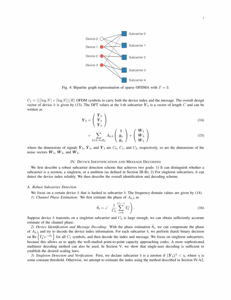
For device k, we let |Bk| = T and the set of subcarriers is equally likely to be any T -element subset of{0, · · · , B − 1}. In other words, every device transmits on exactly T out of B subcarriers. Fig. 4 illustrates anexample for the case of T = 3.
The last subframe consists of C3 time-domain samples with low auto-correlation, which are used to estimatedevice delays. Delays may be estimated by performing the correlation between the received signal and the pilotsamples. In particular, the pilot samples are i.i.d. random Rademacher variables with length greater than M .
D. Massive Access with Device Identification and Message Decoding
Similar to embedding the device index information through gk, each device can encode both a dlogNe-bitdevice index information and a dlogSe-bit message information through gk. With a code rate of R, we have
7
Subcarrier 0
Subcarrier 1
Subcarrier 2
Subcarrier 3
Subcarrier 4
Device 0
Device 1
Device 2
Device 3
Fig. 4: Bipartite graph representation of sparse OFDMA with T = 3.
C1 = d(dlogNe+dlogSe)/Re OFDM symbols to carry both the device index and the message. The overall designvector of device k is given by (13). The DFT values at the b-th subcarrier Y b is a vector of length C and can bewritten as
Y b =
Y b
Y b
Y b
(14)
=∑
k∈K:b∈BkAk,b
1gkgk
+
W b
W b
W b
(15)
where the dimensions of signals Y b, Y b, and Y b are C0, C1, and C2, respectively, so are the dimensions of thenoise vectors W b, W b, and W b.
IV. DEVICE IDENTIFICATION AND MESSAGE DECODING
We first describe a robust subcarrier detection scheme that achieves two goals: 1) It can distinguish whether asubcarrier is a zeroton, a singleton, or a multiton (as defined in Section III-B); 2) For singleton subcarriers, it candetect the device index reliably. We then describe the overall identification and decoding scheme.
A. Robust Subcarrier Detection
We focus on a certain device k that is hashed to subcarrier b. The frequency-domain values are given by (14).1) Channel Phase Estimation: We first estimate the phase of Ak,b as
θb = ∠
(1
C0
C0−1∑
c=0
Y cb
). (16)
Suppose device k transmits on a singleton subcarrier and C0 is large enough, we can obtain sufficiently accurateestimate of the channel phase.
2) Device Identification and Message Decoding: With the phase estimation θb, we can compensate the phaseof Ak,b and try to decode the device index information. For each subcarrier b, we perform (hard) binary decisionon Re
{Y cb e
−ιθb}
for all C1 symbols, and then decode the index and message. We focus on singleton subcarriers,because this allows us to apply the well-studied point-to-point capacity approaching codes. A more sophisticatedmultiuser decoding method can also be used. In Section V, we show that single-user decoding is sufficient toestablish the desired scaling laws.
3) Singleton Detection and Verification: First, we declare subcarrier b is a zeroton if ‖Y b‖2 < η, where η issome constant threshold. Otherwise, we attempt to estimate the index using the method described in Section IV-A2,

8
assuming subcarrier b is a singleton. Suppose k is the estimated index. We perform the following validation process.We estimate the nonzero signal as
Ak,b =1
C2g†kY b, (17)
where gck, c = 0, · · · , C2 − 1, are as described in Section III-C. Then we declare that subcarrier b is a singleton ifand only if it passes the energy threshold test, i.e.,
||Y b − Ak,bgk||22 ≤ η. (18)
The above validation scheme is similar to that used for sparse DFT and sparse Walsh-Hadamard transform (WHT),where the singleton verification approach has been proved to be correct with high probability for signal amplitudeslying in a known discrete alphabet [34], [35]. In this paper, we further show that it can effectively identify thesingletons for arbitrary analog amplitudes that are bounded away from zero, as specified in Theorems 1 and 2.
4) Overall Subcarrier Detection: Based on the preceding process, the robust subcarrier detection algorithm isillustrated in Algorithm 1. For each subcarrier b, the DFT values is decomposed into three segments as in (14).If the subcarrier is not a zeroton, we first estimate the phase of channel coefficient based on Y b, which is usedto compensate the phase of Y b. We then estimate the device index as k. The channel coefficient is estimated asAk,b according to (17). If (18) is satisfied, a singleton is declared, the device k is estimated to be active, and themessage is decoded. Otherwise, a multiton is declared.
Algorithm 1 Robust-Subcarrier-Detect (Y )
Input: Subcarrier values Y =(Y†, Y†, Y†)†
, where Y ∈ CC0 , Y ∈ CC1 and Y ∈ CC2 .Output: Declaration of zeroton/singleton/multiton, and estimates of index and data if applicable.if ||Y ||2 < η then
declare zeroton and return.end ifθ ← phase
(1T Y /C0
).
Z ← Re{Y e−ιθ}.(k, ˆgk)← Decode(Z).
Ak ← g†kY /C2.
if ||Y − Akgk||22 ≤ η thendeclare singleton and return
(k, ˆgk
).
elsedeclare multiton and return.
end if
B. Overall Framework
Once a device index is estimated based on a singleton, its contributions to all its connected subcarriers arecanceled out, which may result in new singleton subcarriers. For example, in Fig. 4, device 1 is first detected fromthe singleton subcarrier 0 and its values are subtracted from subcarrier 2. Then subcarrier 2 becomes a singletonsubcarrier and device 2 can be detected from it. There is, however, one challenge. The DFT values from each deviceat a subcarrier depends on its delay due to (10). We need to estimate the delay using subframe 3 of the receivedsignal in order to perform successive cancellation.
Let I denote the time-domain indices corresponding to the last subframe with the first M samples skipped.Define the decision statistic based on I as:
Tk(m) =∑
i∈Iyi+ms
∗k,i+M . (19)
The reason of discarding the first M samples in the last subframe is to guarantee that the cross-correlation of thepilot sequences between different users is performed entirely on the Rademacher random variables. We estimate

9
Algorithm 2 Asynchronous Massive Access via Sparse OFDMA
Input: Subcarrier values Y b, b = 0, · · · , B − 1.Output: Detected active device set K and their messages.Initialize: Set B to be the set of all subcarriers. Set K and L to be the empty set.for every subcarrier b do
if Robust-Subcarrier-Detect (Y b) declares a singleton(k, ˆgk
)then
Add k to L.end if
end forwhile fewer than K iterations and L is not empty do
Pick arbitrary k ∈ L, remove k from L, and add k to K .Estimate mk and ak according to (20) and (21).Set S to be the set of subcarriers in B that are connected with k.for every subcarrier b′ ∈ S do
Cancel the signal of device k from subcarrier b′ using (22).if Robust-Subcarrier-Detect (Y b′) declares a zeroton or a singleton
(k, ˆgk
)then
Remove b′ from B.Add k to L (if a singleton is declared).
end ifend for
end while
the delay of device k as
mk ∈ arg maxm=0,··· ,M−1
Re{Tk(m)}. (20)
The channel coefficient is then estimated to be
ak =1
Cg†kY be
− ι2πb(M−mk)
B . (21)
The DFT values of a connected unprocessed subcarrier b′ are then updated according to
Y b′ ← Y b′ − ak exp
(ι2πb′(M − mk)
B
)gk. (22)
The overall massive access framework is described in Algorithm 2. Throughout the algorithm, we maintain threelists: K is a list storing the estimated device indices, L is a list of detected devices for cancellation, and B is alist of surviving subcarriers. We first detect all singleton subcarriers and identify their corresponding devices usingAlgorithm 1. Then we successively cancel each identified device, potentially exposing more singletons along theway to allow more devices to be identified. This process continues until no singleton subcarrier is left.
We next prove that the preceding sparse OFDMA can efficiently identify the active devices and decode theirmessages. We will first prove the synchronous case (M = 0) in Section V, and then extend the proof to theasynchronous case in Section VI.
V. PROOF OF THEOREM 1 (THE SYNCHRONOUS CASE)
A. Key Parameters and Propositions
For codeword construction, we choose constants
T ≥ 3 (23)
andβ0 ≥ T (T − 1) + 1, (24)

10
e.g., by letting T = 3 and β0 = 7. We also set the following parameters as
B = β0K (25)C0 = dlogNe (26)C1 = d(dlogNe+ dlogSe)/Re (27)C2 = dβ1 logKe, (28)
where β1 > 0 is a constant to be specified in Appendix B, and R < 1 is a constant denoting the rate of alow-complexity capacity-approaching code for the binary-symmetric channel (BSC) to be further explained inAppendix C. The total number of OFDM symbols is
C ≤ (1 + d1/Re)dlogNe+ d1/RedlogSe+ dβ1 logKe. (29)
The codelength L = BC = β0KC thus satisfies (2) as long as β0, β1, and R are positive constants.In this proof, we shall invoke several results about hypergraphs. A hypergraph is a generalization of a graph in
which an edge can join any number of vertices. An edge in a hypergraph is also called a hyperedge. A hypergraphis a hypertree if the graph is a tree, i.e., no cycle exists. A hypergraph is a unicyclic component if the graph containsonly one cycle. A T -uniform hypergraph is a hypergraph where all the hyperedges have degree-T . Here we let thedevice nodes become hyperedges and the subcarriers become hypergraph vertices. A hyperedge is incident on avertex if the corresponding device node is connected to the corresponding subcarrier.
Let G denote the bipartite graph induced by the active devices (see Defition 1). We now characterize the probabilitythat G is such that no two active devices share the same set of subcarriers, so that it is convertible to an equivalenthypergraph (denoted as G ∈ G). Since there are
(BT
)distinct subsets of T subcarriers, we have
P{G ∈ G} =
(B
T
)[(B
T
)− 1
]· · ·[(B
T
)−K + 1
]/((B
T
))K. (30)
Since(BT
)≥ O(K3) for T ≥ 3, we have
P{G ∈ G} ≥ 1− ζ
K(31)
with some constant ζ [36, The birthday problem].By the construction of the sparse OFDMA in Section III-C, every device is associated with exactly T subcarriers,
so the hypergraph induced by the active devices is a (random) T -uniform hypergraph.Definition 2: [An ensemble of hypergraphs] Let G denote the ensemble of T -uniform hypergraphs with K
hyperedges and B vertices that consist of components each of which is either a hypertree or a unicyclic component,where no component has more than αT log(β0K)/(T − 1) hyperedges with some constant α.
In the following, we will first show that there exists α such that G is convertible to a hypergraph in G (denotedas G ∈ G) with high probability (Proposition 1). We then characterize the error propagation effects in the case ofG ∈ G (Proposition 3) and show that the Robust-Subcarrier-Detect makes the correct decision with high probability(Proposition 4). It follows then that synchronous massive access via Algorithm 2 succeeds with high probability(Proposition 2). The following propositions will be proved in Sections V-B to V-E.
Proposition 1: Under (23)-(28), there exist constants K ′0 > 0, and ν > 1 dependent on β0, such that for everyK ≥ K ′0, the hypergraph G satisfies P {G ∈ G} ≥ 1− ν/K.
Proposition 2: If G ∈ G, then Algorithm 2 will detect all active devices and decode their messages correctly aslong as during its execution Algorithm 1 always makes the correct decision.
Proposition 3: Suppose (23)-(28) hold, G ∈ G, and Algorithm 1 always makes the correct decisions in theprevious t − 1 iterations during the execution of Algorithm 2. Let S(t − 1) be the set of recovered devices. Atiteration t, the DFT value at subcarrier b can be expressed as
Y b =∑
k∈K\S(t−1):b∈BkAk,bgk + W b + V b, (32)
where the sum is over the set of active devices that are hashed to subcarrier b and not yet recovered, and V b
is due to the residual channel estimation errors from the recovered devices. Moreover, conditioned on the designparameters g` of the previously identified devices, each entry of V b is Gaussian variable with zero mean andvariance bounded by β2σ
2
B with a constant β2.

11
Proposition 4: Suppose (23)-(28) hold and G ∈ G. There exists a constant η such that for every t = 1, 2, · · · ,conditioned on that Algorithm 1 makes correct decisions in the first t − 1 iterations during the execution ofAlgorithm 2, Algorithm 1 makes a wrong decision with probability no greater than 7K−2 in the t-th iteration.
Assuming Propositions 1-4 hold, we upper bound the massive access error probability Ps as follows. Let Edenote the event that Algorithm 1 makes at least one wrong decision during the execution of Algorithm 2. ByProposition 2, massive access succeeds if G ∈ G and that E does not occur. Evidently,
Ps ≤ P{E|G ∈ G}+ P{G /∈ G|G ∈ G}+ P{G /∈ G}. (33)
Every time a device is recovered, Algorithm 1 is performed on its connected subcarriers. Since there are Kactive devices and each of them is connected to T = O(1) subcarriers, Algorithm 1 runs for at most KT timesthroughout the detection process. By the union bound and the result of Proposition 4,
P{E|G ∈ G} ≤ 1−(
1− 7
K2
)KT(34)
≤ 7T
K. (35)
Combining Proposition 1, (33), and (35), massive access fails with probability
Ps ≤ (7T + ν + ζ)/K. (36)
Therefore, given the choice of T , B, and C, massive access fails with probability less than ε for K ≥ max{(7T +ν + ζ)/ε,K ′0}.
B. Proof of Proposition 1
Let G0 denote the ensemble of T -uniform hypergraphs with K hyperedges and B vertices consisting of onlyhypertrees and unicylic components. For a given constant α, let G1 denote the ensemble of hypergraphs withthe largest component containing fewer than αT log(β0K)/(T − 1) hyperedges, and G2 denote the ensemble ofhypergraphs with the largest component containing fewer than αT logB vertices. Evidently, G = G0 ∩ G1.
Due to our choice of K and B, the T -uniform hypergraph is in the so-called subcritical phase, which guaranteessome simple structural properties. In particular, [37, Theorem 4] establishes that the hypergraph is entirely composedof hypertrees and unicyclic components with high probability. To be precise, the proof in [37] implies that
P{G ∈ G0} ≥ 1− ν − 1
K(37)
for some constant ν > 1 dependent on β0.We next show that there exists a constant α, such that G ∈ G2 with high probability. The size of a hypergraph is
defined as the number of hyperedges K in the graph. The number of vertices in the hypergraph is B. The averagevertex degree of a vertex v is defined as the expected number of pairs of (vi, ei), where vi and ei are some vertexand hyperedge in the graph, such that (v, vi) are connected via hyperedge ei.
Lemma 1: G has an average vertex degree of KT (T − 1)/B.Proof of Lemma 1: Consider a subcarrier b (a vertex). Let Xk = 1 if device k uses subcarrier b, and Xk = 0,
otherwise. Device k has(BT
)equally likely choices for its subcarriers, where
(B−1T−1
)of those choices include
subcarrier b. The average vertex degree is thus calculated as
E
{∑
k∈K(T − 1)Xk
}= K(T − 1)E {Xk} (38)
= K(T − 1)
(B−1T−1
)(BT
) (39)
=KT (T − 1)
B. (40)

12
Consider a random hypergraph with B vertices and range T .2 Since B>KT (T − 1) due to (24) and (25), theaverage vertex degree is less than 1 by Lemma 1. Then it has been shown in [38, Theorem 3.6] that, since G’saverage vertex degree is less than 1, for K ≥ K ′0 with a large enough K ′0, there exists a constant α, such that
P{G ∈ G2} ≥ 1− 1
K. (41)
Let r and s be the number of vertices and hyperedges of a connected component, respectively. If the componentis a hypertree, r = (T −1)s+ 1. If the component is a unicylic component, r = (T −1)s. Therefore, when G ∈ G0
and G ∈ G2, the number of hyperedges in the largest component is upper bounded as
s ≤ r/(T − 1) (42)≤ αT logB/(T − 1) (43)= αT log(β0K)/(T − 1). (44)
It impliesG0 ∩ G2 ⊂ G1. (45)
Therefore, we have
P {G ∈ G} = P {G ∈ (G0 ∩ G1)} (46)≥ P {G ∈ (G0 ∩ G2)} (47)
≥ 1− ν
K, (48)
where (46) follows from Definition 2 and definitions of G0 and G1, (47) is due to (45), and (48) is due to (37) and(41).
C. Proof of Proposition 2
Every graph in G consists of only hypertrees and unicyclic components. By [39, Lemma 3.4], every hypertreehas a hyperedge (device node) incident on at least T − 1 singleton subcarriers. Every unicyclic component has ahyperedge that is incident on either T − 1 or T − 2 singleton subcarriers. When T ≥ 3, every hypergraph in Galways has singleton subcarriers. Assuming Algorithm 1 correctly detects the singleton subcarriers and estimatesthe devices’ indices, the detected devices will be removed from the hypergraph. Since removing any device node orhyperedge in G ∈ G still yields a hypergraph in G, Algorithm 2 will continue until all active devices are correctlydetected.
D. Proof of Proposition 3
We make use of the error propagation graph proposed in [40] to characterize the residual channel estimationerrors. The error propagation graph is a directed subgraph induced by the device identification Algorithm 2. It beginsfrom some singleton subcarriers. Every singleton subcarrier points to the device node that should be detected basedon it. Every device node in the graph points to all subcarriers it is then cancelled from. Fig. 5 illustrates the errorpropagation subgraph concerning device 2. In the error propagation graph, device 0 is estimated from singletonsubcarrier-a and its values are cancelled from the connected subcarrier-b and subcarrier-c. In a subsequent iteration,subcarrier-b becomes a singleton. Device 1 can be detected and its values are cancelled from subcarrier-c. In a thirditeration, subcarrier-c becomes a singleton and device 2 is detected.
Let bk be the immediate singleton subcarrier used to recover the device k. Let Ak be the channel estimationerror of device k defined as
Ak = Ak,bk −Ak,bk , (49)
where bk is the subcarrier which will be used to estimate the device index k, Ak,bk is given by (10) and
Ak,bk = g†kY bk/C (50)
is the estimate according to (21) in this case with no delay.
2The size of the largest edge is called range of the hypergraph. A T -uniform hypergraph has a range of T .

13
a
0
b
c
1
2
0
e0
e0e0g0
e1 + e0
⇣�g†
1g0C�1⌘
e1g1 + e0
⇣�g†
1g0C�1⌘g1 + e0g0
e2 + e1
⇣�g†
2g1C�1⌘
+
e0
h⇣g†
1g0
⌘⇣g†
2g1
⌘C�2 � g†
2g0C�1i
Fig. 5: Error propagation graph for device 2. Device 0 is detected from subcarrier-a at iteration t = 1, device 1 isdetected from subcarrier-b at iteration t = 2, and device 2 is detected from subcarrier-c at iteration t = 3.
We will keep track of the errors using the graph. The error Ak causes cancellation error Akgk to every downstreamsubcarrier node. The errors accumulated by a singleton subcarrier adds to the estimation errors of its downstreamdevice nodes.
Consider the first iteration and a singleton subcarrier bk due to device k. The DFT value of subcarrier-bk is givenby
Y bk = Ak,bkgk + W bk , (51)
so the residual estimation error is given by
Ak = C−1g†kW bk . (52)
At iteration t ≥ 2, with successive cancellation, the updated frequency value at subcarrier b is
Y b =∑
k∈K\S(t−1):b∈BkAk,bgk + W b +
∑
`∈S(t−1):b∈B`
(A`,b` − A`,b`
)g` (53)
=∑
k∈K\S(t−1):b∈BkAk,bgk + W b −
∑
`∈S(t−1):b∈B`A`g`. (54)
Suppose some subcarrier bk is a singleton due to device k and is used to recover the index, then the channelestimation error is calculated as
Ak = C−1g†kY bk −Ak,bk (55)
= C−1g†k
Ak,bkgk + W bk −
∑
`∈S(t−1):bk∈B`A`g`
−Ak,bk (56)
= C−1g†kW bk −∑
`∈S(t−1):bk∈B`C−1A`g
†kg`. (57)
Using recursion, the estimation error of Ak,b for k ∈ S(t)\S(t− 1) is calculated as
Ak = ek +∑
(`0,··· ,`i)∈P(k),`0∈S(t−1)
e`0(−g†kg`i/C)(−g†`ig`i−1/C) · · · (−g†`1g`0/C), (58)
where P(k) = {(`0, · · · , `i) : `0, · · · , `i, k is a path of devices in the error propagation graph}, and e`0 is given

14
by
e`0 = C−1g†`0W b`0. (59)
It is easy to see that every e`0 is independent of the design parameters {gk} of all the devices and is distributedaccording to CN (0, 2σ2/(BC)).
In Fig. 5, for instance, when calculating the estimation error A2 for device node 2, we take into account devicenodes 0 and 1 that have been recovered. In particular, P(2) = {(0, 2), (1, 2), (0, 1, 2)}. For path (0, 2), the productterm in the summation is −e0g
†2g0/C. For path (1, 2), the product term in the summation is −e1g
†2g1/C. For path
(0, 1, 2), the product term in the summation is e0g†2g1g
†1g0/C
2. Consequently, we have A2 = e2 + e0(−g†2g0/C+g†2g1g
†1g0/C
2)− e1g†2g1/C.
Therefore, the DFT value at subcarrier b is calculated as
Y b =∑
k∈K\S(t−1):b∈BkAk,bgk + W b + V b, (60)
whereVb = −
∑
(`0,··· ,`i)∈P′(b),`0∈S(t−1)
e`0(−g†`ig`i−1/C) · · · (−g†`1g`0/C)g`i (61)
where P ′(b) = {(`0, · · · , `i) : `0, · · · , `i is a path of devices to subcarrier b, i.e., device `i points to subcarrier b,in the error propagation graph}.
Suppose G ∈ G, then |P ′(b)| ≤ 2. Moreover, by Proposition 1, the number of left nodes in each component is lessthan αT log(β0K)/(T−1), which indicates that |S(t−1)| ≤ αT log(β0K)/(T−1) ≤ αT logK/(T−1)+2α log β0.Since each entry of the design parameter g` is i.i.d. Rademacher variable and g` ∈ RC , |−g†`ig`i−1
/C| ≤ 1. Thus,for each entry of V b, e`0 has the coefficient satisfying |(−g†`ig`i−1
/C) · · · (−g†`1g`0/C)gc`i | ≤ 1. Combining thefact that e`0 ∼ CN (0, 2σ2/(BC)), each entry of V b is a Gaussian variable with zero mean and variance boundedby 4|S(t− 1)| · 2σ2
BC . Since
8|S(t− 1)|C
≤8αT logK/(T − 1) + 16α log β0
logN + logN/R+ β1 logK(62)
≤8αT/(T − 1) + 16α log β0
1 + 1/R+ β1(63)
according to (26)-(28), the variance is bounded by β2σ2
B , where β2 equals to the right hand side of (63) and is aconstant.
E. Proof of Proposition 4
As described in the proof of Proposition 3, the frequency domain signal in subcarrier-b can be written as (32).The detection error depends on V b and hence on the number of devices that cause interference. Let
Zb = W b + V b (64)
denote the interference plus noise. We set the energy thresholds η.1) Zeroton Error Detection: Suppose subcarrier b is a zeroton. The DFT values in Y b are composed of purely
noise and interference, i.e., Y b = Zb. The zeroton error E0 occurs only if ||Y b|| is greater than the threshold η.Let g denote the set of design parameters gk of all the previously identified devices. Conditioned on g, each entryof Zb is distributed according to CN (0, 2σ2
z), where σz ≤ (1 + β2/2)σ2/B. The probability of error satisfies
P {E0} = E{P{||Zb||2 ≥ η
∣∣g}}
(65)
≤ E
{2C2P
{|Re{Zb,c}|2 ≥
η
2C2
∣∣g}}
(66)
≤ 4C2e− η
4σ2zC2 (67)
≤ 4C2e− Bη
(4+2β2)σ2C2 , (68)

15
where (66) is due to that the real and imaginary elements of Zb are i.i.d. Gaussian variables, and moreover if eachelement has an absolute value bounded by η/(2C2), then the norm of Zb must be bounded by η.
With B and C2 chosen according to (25) and (28), respectively, if we pick η as a constant that satisfies
η ≥ (4 + 2β2)σ2β1dlogKe ln(4K2β1dlogKe)β0K
, (69)
then the error probability satisfies
P{E0} ≤ K−2. (70)
Note that the right hand side of (69) vanishes as K →∞. Hence, there exists such a constant η.2) Singleton Error Detection: Suppose subcarrier b is a singleton due to device k. Let E1 denote the subcarrier
detection error. A singleton detection error occurs due to one or more of three events: (1) E1,0 ={||Y b||22 < η
};
(2) Not E1,0 and E1,1 ={
ˆgk 6= gk
}; (3) E1,2 =
{||Y b − Ak,bgk||22 > η
}. Thus E1 ⊆ E1,0 ∪ E1,1 ∪ E1,2.
We prove
P {E1,0} ≤ 2K−2, (71)
P {E1,1} ≤ K−2, (72)
P{E1,2} ≤ K−2. (73)
in Appendices B, C, and D, respectively.We thus conclude
P {E1} ≤ 4K−2. (74)
3) Multiton Error Detection: It is proved in Appendix E that
P {E2} ≤ 2K−2. (75)
Therefore, combining (70), (74) and (75), we conclude that the robust subcarrier detection makes the correct decisionwith probability higher than 1− 7K−2.
We have thus established Propositions 1-4.
F. Complexity
We perform B-point DFT for C symbols. The computational complexity is O(K(logK)(logN+logS+logK))using FFT operations. In robust subcarrier detection implemented after initialization of Algorithm 2, for eachsubcarrier, the phase estimation involves O(logN) operations, the device identification and message decodinginvolves O(logN + logS) operations, and the singleton detection and verification involves O(logK) operations.The while loop of Algorithm 2 will be implemented no more than K times. In each while loop, delay estimationis neglected when M = 0. For every subcarrier b′ ∈ S, where |S| ≤ T , the cancellation of signal of the detecteddevice involves O(logN + logS + logK) operations. The robust subcarrier detection for subcarrier b′ invlovesO(logN + logS + logK) operations. Since T is a constant, the while loop involves no more than O(K(logN +logS + logK)) operations. As a result, the complexity of DFT dominates, leading to the total computationalcomplexity of O (K(logK)(logN + logS + logK)).
Hence the proof of Theorem 1.
VI. PROOF OF THEOREM 2 (THE ASYNCHRONOUS CASE)
In the asynchronous massive access case, we choose the parameters according to (23)–(28). The last subframein Fig. 3 consists of C3 = M + dβ3K log(KM + 1)e samples, where β3 ≥ 64a2/a2. The total codelength intransmitted symbols is thus
L =(B +M)C + C3 (76)
=(β0K +M)((1 + d1/Re)dlogNe+ d1/RedlogSe+ β1dlogKe
)+M + dβ3K log(KM + 1)e. (77)
Thus the codelength satisfies (3) for some α0 > 0. The FFT operation and channel estimation involve the samenumber of operations as the synchronous case. Different from the synchronous case, each device needs to estimate

16
its delay once. The complexity of delay estimation is O(M(M + K log(KM + 1)) (corresponding to M timesauto-correlations). A total of K devices need to estimate their delays. The total computational complexity is thusO (K(logK)(logN + logS + logK)) +O
(KM2 +K2M log(KM + 1)
).
The following lemma shows that for each device the delay estimate is correct with high probability.Lemma 2: Suppose the conditions specified in Theorem 2 hold. Suppose the bipartite graph G ∈ G and the
parameters are chosen according to (23)–(28). Suppose β3 ≥ 64a2/a2 and is chosen to be an integer, and C3 =M + dβ3K log(KM + 1)e samples are used for delay estimation, the delay of a device estimated according to (20)is correct with probability no less than 1− 4/K2.
The proof of Lemma 2 is relegated to Appendix F.Denote by V the event that the delay estimation of all devices is correct. Then we have P{V|G ∈ G} ≥ 1− 4/K
by the union bound and Lemma 2. Conditioned on that the device delays are correctly detected, the residual errorsof channel estimation can be characterized in the same manner as the synchronous case. Thus, the error probabilitycan be upper bounded by
Ps ≤ P{E|G ∈ G}+ P{G /∈ G|G ∈ G}+ P{G /∈ G}, (78)
where
P{E|G ∈ G} ≤ P{V|G ∈ G}+ P{E|V, G ∈ G}P {V|G ∈ G} (79)
≤ 4
K+ P{E|V, G ∈ G} (80)
≤ 4
K+ 1−
(1− 7
K2
)KT(81)
≤ 4
K+
7T
K, (82)
where (81) is according to Proposition 4. We thus have
Ps ≤4 + 7T + ν + ζ
K(83)
according to Proposition 1, (78), and (82).Theorem 2 is proved with K0 = max{(4 + 7T + ν + ζ)/ε,K ′0}, and α1 being some constant due to the FFT
operation.
VII. SIMULATION RESULTS
Without loss of generality, we focus on the performance of device identification via sparse OFDMA throughout allsimulations. Specifically, the total number of devices is N = 238, which is over 274 billion. (Alternatively, one canhave one million devices where each active device can transmit log(274000) ≈ 18 bits). The performance of sparseOFDMA will be compared with two random acces schemes, namely slotted ALOHA and CSMA. Throughout thesimulation, the channel coefficient amplitude is uniformly randomly generated from [1, 2] and the phase is uniformlyrandomly generated from [0, 2π]. The received SNR is defined as SNR = 10 log(1/(2σ2)), where σ2 is the noisevariance per dimension.
A. Synchronous device identification
We first investigate the error probability of synchronous device identification via sparse OFDMA. We choose theparameters as B = d2.5Ke, C0 = C2 = 4. The code rate R = 0.5 is used to encode the device index, and thusC1 = 2dlogNe. The number of subcarriers assigned to each device is T = 3.
Fig. 6 shows the error probability of synchronous device identification. In each simulation, if there exists misseddetection or false alarm, an error is registered. Throughout the simulation, the false positive rates is smaller than10−5 for the SNRs in the region of interest, and thus we do not plot the results here. Fig. 7 shows the miss rate,defined as the average number of misses normalized by the number of active devices K. Simulation shows thatwith a code length of 10500, sparse OFDM can achieve a miss detection rate lower than 10−3 at SNR=−10 dB.In the case of a 20 MHz channel bandwidth, the transmission time is approximately 0.5 ms.

17
Fig. 6: Error probability of device identification in the case of synchronous transmission, where N = 238.
Fig. 7: Rate of missed detection in the case of synchronous transmission, where is N = 238.
B. Asynchronous device identification
We next investigate the error probability of asynchronous device identification. We choose the parameters asB = d2.5Ke, C0 = C2 = 4. The code rate R = 0.5 is used to encode the device index, and thus C1 = 2dlogNe.The number of time-domain samples used for delay estimation is C3 = 1000 for both cases of K = 10 andK = 50, and C3 = 2000 for K = 100. The device population is N = 238 and the maximum delay in terms oftransmit samples is M = 20. Fig. 8 shows the error probability of asynchronous device identification. Fig. 9 showsthe missed detection rate (per active user), respectively. As in the synchronous setting, the error probability is lowunder moderate SNR, which confirms our theoretical analysis.
C. Comparison with random access
1) Slotted ALOHA: First, consider slotted ALOHA, where every device transmits a frame with probability pindependently in each slot over an Ns-slot period. The probability of one given neighbor being missed is equal to

18
Fig. 8: Error probability of device identification in the case of discrete delay. The device population is N = 238
and the maximum delay is M = 20.
Fig. 9: Rate of missed detection in the case of discrete delay. The device population is N = 238 and the maximumdelay is M = 20.
the probability that the device is unsuccessful in all Ns slots:
Pmiss,aloha =(1− (1− p)K−1p
)Ns. (84)
Setting p = 1/K minimizes Pmiss,aloha.2) CSMA: It is challenging, if not impossible, to implement CSMA-based wireless access. Due to the power
asymmetry between devices and access points, a device may not be able to sense another device’s transmission inthe same cell. Suppose, nonetheless, devices can sense each other and CSMA is used. When the channel is idle, thedevices start their timers. The device whose timer expires the first transmits. When the channel becomes busy, thedevices stop their timers. Device i has a chance to transmit if its timer is the minimum in some slot. The probability

19
that a given device never gets a chance to transmit is
Pmiss,csma = (1− P {T1 < min{T2, · · · , TK}})Ns . (85)
In order to reliably transmit the device index logN bits, the number of symbols required in each frame is at leastdlogNe/ log(1 + SNR). Therefore, the total number of symbols required is NsdlogNe/ log(1 + SNR), where Nsdepends on the target miss rate. Under SNR = -10 dB, it can be seen from Fig. 9 that sparse OFDMA can achievemissed detection rate low than 10−3 for K = 10, 50 or 100. We can calculate the number of symbols required byslotted ALOHA and CSMA to achieve a comparable miss detection rate of 10−3 at SNR = -10 dB. When K = 50,the code length of sparse OFDMA is around 10,500, while slotted ALOHA and CSMA requires more than 90,000symbols to achieve a missed detection rate of 10−3. Sparse OFDMA can effectively reduce the code length by over80%. Moreover, the code length reduction is even greater for larger K and a lower error probability requirement.When K = 100, the code length of sparse OFDMA is around 21,000, while slotted ALOHA and CSMA requiresmore than 180,000 symbols to achieve a missed detection rate of 10−3. Sparse OFDMA can effectively reduce thecode length by over 85%. The significant reduction of the code length required by sparse OFDM is due to the codedesign, which utilizes the sparsity of the active users among the total number of users.
VIII. CONCLUSION
We have proposed a low-complexity asynchronous neighbor discovery and massive access scheme for verylarge networks with billions of nodes. The scheme may find important applications in the Internet of Things.The scheme, referred to as sparse OFDMA, applies the recently developed sparse Fourier transform to compresseddevice identification. Compared with random access schemes, sparse OFDMA requires much shorter code length byexploiting the multiaccess nature of the channel and the multiuser detection gain. Sparse OFDMA is a divide-and-conquerapproach of low complexity, where only point-to-point capacity approaching codes are adopted. It provides practicalphysical layer capability for multipacket reception.
APPENDIX AAUXILIARY RESULTS ON SUB-GAUSSIAN VARIABLES
We introduce the definition of sub-Gaussian variables, which will be used in the proof of the main theorems.Definition 3: X is σ-subGaussian if there exists σ > 0 such that
E {exp(tX)} ≤ exp(σ2t2/2), ∀t ≥ 0. (86)
Definition 4 (subGaussian norm): The subGaussian norm of the random variable X is defined as
||X||φ2 = supp≥1
p−1/2 (E|X|p)1/p. (87)
The following three lemmas, which are established in [41], will be used in the proof.Lemma 3: Suppose X is σ-subGaussian, then aX is aσ-subGaussian.Lemma 4: Suppose X1 is σ1-subGaussian, X2 is σ2-subGaussian. Moreover, they are independent. Then X1 +X2
is√σ2
1 + σ22-subGaussian.
Lemma 5: If a random variable X is σ-subGaussian with zero mean, then for any t > 0, the following holds
P{X > t} ≤ e− t2
2σ2 (88)
P{X < −t} ≤ e− t2
2σ2 . (89)
The following theorem characterizes the properties of subGaussian variables [41].Theorem 3 (Characterization of subGaussian variables): Let EX = 0. The following are equivalent:1) E(etX) ≤ e t
2
4 .2) ∀p ≥ 1, (E|X|p)1/p ≤ √2p.The following theorem is on the concentration of subGaussian random variables.Theorem 4 (Hanson-Wright inequality [42]): Let Z = (Z1, · · · , Zn) ∈ Rn be a random vector with independent
components Zi which satisfy EZi = 0 and the subGaussian norm ||Zi||φ2≤ K. Let A be an n× n matrix. Then,
for every t ≥ 0,
P{|ZTAZ − E
{ZTAZ
}| > t
}≤ 2 exp
[−ς min
(t2
K4||A||2F,
t
K2||A||
)], (90)

20
where the operator norm of A is ||A|| = maxx 6=0||Ax||2||x||2 , the Frobenius norm of A is ||A||F = (
∑i,j |Ai,j |2)1/2
and ς is an absolute constant that does not depend on K,A and t.
APPENDIX BPROOF OF SINGLETON ERROR E1,0 (71)
We first establish the following lemma, which is key to the proof of (71).Lemma 6: Let B be given by (25). Let 0 ≤ c < C2 and β2 ≥ 0 be some fixed constants. Let each entry of
Z ∈ CC2 be distributed according to CN (0, 2σ2z), where σz ≤ (1 + β2/2)σ2/B. Let Q = UΛΛΛU †, where U is a
real-valued orthogonal matrix and ΛΛΛ = diag{0, · · · , 0, 1, · · · , 1} is a diagonal matrix with c zeros and C2− c ones.Let
S =
k0∑
k=1
Ak,bgk, (91)
where k0 ≥ 1, the entries of gk are i.i.d. Rademacher variables, and |Ak,b| ≥ a. Then there exists some β1 suchthat the following holds for large enough K:
P{||QS + Z||22 ≤ η
}≤ 2
K2, (92)
where C2 depends on β1 according to (28) and η is the energy threshold.
Proof: In the following, we use∑k as a shorthand for
∑k0
k=1. We have
P{||QS + Z||22 ≤ η
}≤P{||QS + Z||22 ≤ η
∣∣∣∣||QS||22 ≥ ϑ}
+
P{||QS||22 ≤ ϑ
}, (93)
where the threshold ϑ is defined as
ϑ =1
2(C2 − c)
∑
k
|Ak,b|2. (94)
(Note (C2−c)∑k |Ak,b|2 is the expectation of ‖QS‖22, hence the choice of threshold as a half of the expectation.)
To bound the first term on the right hand side of (93), we use the triangular inequality ||Z||2 + ||QS + Z||2 ≥||QS||2 to obtain
P
{||QS + Z||22 ≤ η
∣∣∣∣||QS||22 ≥ ϑ}
≤ P
{||QS||2 − ||Z||2 ≤
√η
∣∣∣∣||QS||22 ≥ ϑ}. (95)
For large enough K, η can be chosen to be an arbitrarily small constant to satisfy (69). Recall C2 = dβ1 logKe asgiven by (28), for any fixed c, we have ϑ ≥ 1
2 (C2− c)a2, which is greater than 4η for large enough K. Therefore,for large enough K,
P
{||QS||2 − ||Z||2 ≤
√η
∣∣∣∣||QS||22 ≥ ϑ}
≤ P
{||Z||2 ≥
√η
∣∣∣∣||QS||22 ≥ ϑ}
(96)
≤ 1/K2, (97)
where (97) follows from (65) and (70).The second term on the right hand side of (93) is derived in the following steps. We first show that the real
and imaginary parts of S given by (91) are subGaussian variables. Then, we show that ||QS||22 are concentratedaround (C2− c)
∑k |Ak,b|2 with high probability using the large deviation results on subGaussian variables. In the
following, we denote XR and XI as the real and imaginary component of X , respectively.Lemma 7: Let SR = (S0,R, · · · , SC2−1,R) and SI = (S0,I , · · · , SC2−1,I) be the real and imaginary components
of S, respectively. Then Sc,R are i.i.d.√∑
k
A2k,R-subGaussian random variables with ESc,R = 0 and the subGaussian

21
norm satisfies ||Sc,R||φ2≤ 2
√∑k
A2k,R. Similarly, Sc,I are i.i.d.
√∑k
A2k,I -subGaussian random variables with
ESc,I = 0 and the subGaussian norm satisfies ||Sc,I ||φ2≤ 2√∑
k
A2k,I .
Proof: Since gck is Rademacher variable, it is 1-subGaussian with mean zero. Thus, ESc,R = 0. Moreover, gckare independent across k. According to Lemma 3 and Lemma 4, Sc,R =
∑k Ak,Rg
ck is
√∑k
A2k,R-subGaussian.
{Sc,R}C2−1c=0 are independent, because gck are independent across c = 0, · · · , C2 − 1.
By Definition 3, E {exp(tSc,R)} ≤ exp
(∑k
A2k,Rt
2/2
). Let X = Sc,R/
√2∑k
A2k,R. Then E {exp(tX)} ≤
exp(t2/4). According to Theorem 3, for all p ≥ 1, (E|X|p)1/p ≤ √2p, which yields
(E|Sc,R|p)1/p ≤ 2
√∑
k
A2k,Rp. (98)
By (87), the subGaussian norm of Sc,R is upper bounded as ||Sc,R||φ2≤ 2
√∑k
A2k,R. The statement for the
imaginary parts follow similarly.
In order to apply Theorem 4 to provide a concentration result on ||QS||, we need to first derive the Frobeniusnorm and the operator norm of Q. The Frobenius norm of Q is calculated as
||Q||2F = tr{QQ†} (99)= tr{Q} (100)= C2 − c, (101)
where (100) follows by QQ† = Q, and (101) follows because the sum of the eigenvalues of Q is C2 − c.Since the largest eigenvalue of Q is 1, the operator norm of Q is calculated as
||Q|| = maxx6=0
||Qx||2||x||2
= 1. (102)
Conditioned on gk0,
E{||QSR||22
}= E
{S†RQQ†SR
}(103)
= E{S†RQSR
}(104)
= E{S2c,R}tr{Q} (105)
= (C2 − c)∑
k
A2k,R, (106)
where (105) follows because {Sc,R}C2−1c=0 are i.i.d. distributed. Similarly, E
{||QSI ||22
}= (C2 − c)
∑k A
2k,I .
Applying Theorem 4 with Z = SR, A = Q with ||Q|| = 1, ||Q||2F = C2 − c and K = 2√∑
k
A2k,R yields
P
{∣∣∣∣||QSR||22 − (C2 − c)∑
k
A2k,R
∣∣∣∣ > t
}≤
2 exp
(−ς min
(t2
16(C2 − c)(∑k A
2k,R)2
,t
4∑k A
2k,R
)), (107)
where ς is a constant introduced in Theorem 4 in Appendix A.Letting t = (C2 − c)
∑k A
2k,R/2, we have
P
{||QSR||22 ≤
(C2 − c)∑k A
2k,R
2
}≤ 2 exp
(− ς
64(C2 − c)
). (108)

22
Similarly, we have
P
{||QSI ||22 ≤
(C2 − c)∑k A
2k,I
2
}≤ 2 exp
(− ς
64(C2 − c)
). (109)
Since Q is a real-valued matrix, ||QS||22 = ||QSR||22 + ||QSI ||22. Moreover,∑k |Ak,b|2 =
∑k
(A2k,R +A2
k,I
).
Combining (108) and (109), we have
P
{||QS||22 ≤
(C2 − c)∑k |Ak,b|2
2
}≤ P
{||QSR||22 ≤
(C2 − c)∑k A
2k,R
2
}+ P
{||QSI ||22 ≤
(C2 − c)∑k A
2k,I
2
}
(110)
≤ 4 exp(− ς
64(C2 − c)
). (111)
Combining (93), (97) and (111), there exists some large enough β1 such that for C2 = dβ1 logKe,
P{||QS + Z||22 ≤ η
}≤ 2
K2. (112)
The probability that a singleton is declared to be a zeroton is calculated as
P {E1,0} = P{||Ak,bgk + Zb||22 ≤ η
}. (113)
Therefore, we can apply Lemma 6 with S = Ak,bgk, Q = I , Z = Zb, k0 = 1, and c = 0 to obtain (71). In thiscase, β1 can be chosen to satisfy β1 ≥ 192/ς such that 4 exp
(− ς
64dβ1 logNe)≤ K−2.
APPENDIX CPROOF OF SINGLETON ERROR E1,1 (72)
We first show that the phase compensation is accurate with high probability. Second, we show that the interferenceonly causes a slight degradation of signal strength with high probability. Third, the device index recovery can beregarded as transmission over a BSC channel and a large enough C1 can help recover the index information.
We estimate the phase of θ = ∠Ak,b according to (16). Then the estimated phase is calculated as
θ = ∠(Ak,b + Z
), (114)
where Z =C0−1∑c=0
(W cb + V cb
)/C0 is Gaussian distributed with zero mean and variance 2σ2
z conditioned on the
design parameters, where σ2z ≤ (1 + β2/2) σ2
BC0. From the geometric interpretation, the maximum phase offsets
occurs when the noise is orthogonal to the measurement. We choose a small θ0 such that θ0 <π3 and sin θ0 > θ0/2,
then
P{|θ − θ| > θ0
}≤ E
{P
{arcsin
|Z||Ak,b|
> θ0
}|g}
(115)
≤ E{P{|Z| > a sin θ0
}|g}
(116)
≤ E
{P
{|Z| > aθ0
2
}|g}
(117)
≤ E
{2P
{|Re{Z}| > aθ0
2√
2
}|g}
(118)
≤ 4 exp
(− a
2θ20
16σ2z
), (119)
where (119) is due to P{X > x} ≤ e−x2/2 with X ∼ N (0, 1) being the standard Gaussian random variable. For

23
|θ − θ| ≤ θ0,
Re{Ak,be
−ιθ}≥a cos
(θ − θ
)(120)
≥a cos θ0 (121)≥a/2. (122)
Therefore, given B = β0K and C0 = dlogNe, we have
P{
Re{Ak,be
−ιθ}≥ a/2
}≥ 1− 4 exp
(−a
2θ20β0K logN
(16 + 8β2)σ2
). (123)
To predict gck, we make (hard) binary decision on
Re{Y cb e
−ιθ}
= Re{
(Ak,bgck + V cb + W c
b )e−ιθ}
(124)
= Re{Ak,bg
cke−ιθ}
+ Re{Zcbe
−ιθ}, (125)
where Zcb = V cb + W cb is distributed according to CN (0, 2σ2
z) with σ2z ≤ (1 + β2/2)σ2/B, conditioned on the
design parameters. We consider the corruption of signal strength from interference plus noise. Thus, the predictionerror for gck occurs when gckRe{Zcbe−ιθ} < −Re{Ak,be−ιθ}. Then the flip rate can be upper bounded by
P{
Re{Ak,be
−ιθ}< a/2
}+ P
{Re{Ak,be
−ιθ}≥ a/2, gckRe{Zcbe−ιθ} < −Re{Ak,be−ιθ}
}, (126)
where the first termP{
Re{Ak,be
−ιθ}< a/2
}≤ 4 exp
(−a
2θ20β0K logN
(16 + 8β2)σ2
)(127)
according to (123), and the second term
P{
Re{Ak,be
−ιθ}≥ a/2, gckRe{Zcbe−ιθ} < −Re{Ak,be−ιθ}
}
≤ P{gckRe{Zcbe−ιθ} < −a/2
}(128)
≤ P{−|Zcb | < −a/2
}(129)
= exp
(− a2
8σ2z
)(130)
≤ exp
(− a2β0K
(8 + 4β2)σ2
), (131)
where (129) is due to gckRe{Zcbe−ιθ} ≥ −|Zcb |, and (130) is because |Zcb | follows a Rayleigh distribution since Zcb ∼CN (0, 2σ2
z). Combining (126), (127) and (131), the flip rate can be upper bounded by 4 exp(−a
2θ20β0K logN
(16+8β2)σ2
)+
exp(− a2β0K
(8+4β2)σ2
). This indicates that the flip rate tends to 0 when K,N → ∞. By [33, Theorem 6.1], there
exists a code rate that depends only on the given flipping rate of the binary symmetric channel, to encode the(dlogNe+dlogSe)-bit information, such that the index can be recovered correctly with probability at least 1−1/N2.For large enough K, the flipping rate e−O(K) vanishes. Thus, incorrect device identification and message decodingoccurs with probability
P {E1,1} ≤ N−2 ≤ K−2. (132)
with a certain fixed rate R.
APPENDIX DPROOF OF SINGLETON ERROR E1,2 (73)
Let Ak,b = g†kY b/C2. We have
Y b − Ak,bgk =
(I − 1
C2gkg
†k
)Zb. (133)

24
Let Q = I − 1C2
gkg†k. Since g†kgk = C2, gk is the eigenvector of gkg
†k/C2. Since gkg
†k/C2 is a rank-1 matrix, it
has only a single nonzero eigenvalue which is 1. Therefore, the eigenvalue decomposition of Q can be written as
Q = UΛU † (134)
= Udiag{0, 1, · · · , 1}U † (135)
where U is an orthogonal matrix. Then we have
||Y b − Ak,bgk||22 = ||QZb||22 (136)
= ||ΛU †Zb||22 (137)
=
C2−1∑
c=1
|Z ′c|2, (138)
where Z ′ = U †Zb and (138) is due to Λ = diag(0, 1, · · · , 1). Since ||Zb||22 = ||Z ′||22, we have
P{||Y b − Ak,bgk||22 ≥ η
}= P
{C2−1∑
c=1
|Z ′c|2 ≥ η}
(139)
≤ P{||Zb||22 ≥ η
}(140)
≤ K−2, (141)
where (141) follows from (65) and (70).
APPENDIX EPROOF OF MULTITON ERROR (75)
We rewrite the subcarrier values as follows,
Y b =∑
k∈K:b∈BkAk,bgk + Zb, (142)
where Zb = W b + V b.Suppose the incorrect estimate index from subcarrier-b is kb. We have
Akb =∑
k∈K:b∈Bk
1
C2Ak,bg
†kbgk +
1
C2g†kbZb. (143)
Thus,
Y b − Akb gkb =∑
k∈K:b∈BkAk,b
(I −
gkb g†kb
C2
)gk +
(I −
gkb g†kb
C2
)Zb. (144)
Let
S =∑
k∈K:b∈BkAk,bgk (145)
and Q = I − 1C2
gkb g†kb
, then the first term in (144) can be written as
∑
k∈K:b∈BkAk,b
(I −
gkb g†kb
C2
)gk = QS. (146)
The multiton subcarrier cannot be detected when ||Y b − Akb,bgkb ||22 ≤ η. In the following, we upper boundthe error probability assuming kb /∈ {k ∈ K : b ∈ Bk}. A similar analysis can be carried out for the case ofkb ∈ {k ∈ K : b ∈ Bk}. Conditioned on gkb , we can apply Lemma 6 with c = 1, k0 = |k ∈ K : b ∈ Bk| and

25
Z = QZb to upper bound the error probability as
P{||Y b − Akb,bgkb ||22 ≤ η|gkb
}= P
{||QS + QZb||22 ≤ η|gkb
}(147)
≤ 2K−2, (148)
where (148) directly follows from (92). Since (147) holds for every gkb , we have
P{||Y b − Akb,bgkb ||22 ≤ η
}≤ 2K−2. (149)
APPENDIX FPROOF OF LEMMA 2
We focus on the delay estimation for device k. Without loss of generality, we assume the delay is mk = 0. Thedevice experiences the interference from the other K − 1 devices and noise. The received synchronization pilotscan be written as
xi = aksk,i +∑
p∈K\kapsp,i−mp + wi, (150)
where the time-domain samples of the pilots sk,i are uniform random from {+1,−1} and the noise wi ∼CN (0, 2σ2).
Let I denote the samples in the last subframe with the first M samples discarded. The number of samplescontained in I is |I| = dβ3K log(KM + 1)e, β3 ≥ 64a2/a2. Since the random sequence has a length greater thanM and the delay is less than M , without noise, correlating the second segment with the received sequence willyield an auto-correlation of a sequence with its cyclic shift version. According to (19), the test metric is calculatedas
T (m) =
{ |I|ak +∑i∈I wi+Msk,i+M +
∑p∈K\k
∑i∈I apsp,i+M−mpsk,i+M if m = 0∑
i∈I aksk,i+M+msk,i+M +∑p∈K\k
∑i∈I apsp,i+M+m−mpsk,i+M +
∑i∈I wi+M+msk,i+M if m 6= 0.
(151)
By the choice of the random sequence, when p 6= k, sp,i+M+m−mps∗k,i+M are i.i.d. Rademacher variables, for all
p and i ∈ I. Moreover, when m 6= 0, sk,i+M+msk,i+M are i.i.d. Rademacher variables for all i ∈ I. We will showthat with a large enough of β3, the error probability can be lower than O(1/K2).
Define a threshold T = a|I|/2. If Re{T (0)} > T and Re{T (m)} < T for all m = 1, · · · ,M − 1, the delaycan be correctly estimated. Therefore, the error probability can be upper bounded as
Pe ≤M−1∑
m=1
P{Re{T (m)} ≥ T }+ P{Re{T (0)} ≤ T }. (152)
Let rk,i be random i.i.d. Radamacher variables for all k ∈ K and i ∈ I. Let zi = Re{wi} be the real part of therandom noise wi. For m = 1, · · · ,M − 1, we have
P{
Re{T (m)} ≥ T}≤ P
∑
p∈K
∑
i∈Iaprp,i ≥ T /2
+ P
{∑
i∈Izi+M+msk,i+M ≥ T /2
}. (153)
We first derive the upper bound for the second term in (153). Conditioned on sk,i+M , k ∈ K and i ∈ I, thevariables zi+M+msk,i+M are i.i.d. Gaussian variables with mean zero and variance σ2. Therefore,
P
{∑
i∈Izi+M+msk,i+M ≥ T /2
}= Q
(T
2√|I|σ2
)(154)
≤ e−T2
8|I|σ2 (155)
= e−a2|I|32σ2 . (156)
We then derive the upper bound for the first term in (153).

26
Rademacher variables are 1-subGaussian with mean zero. According to Lemma 3 and Lemma 4,∑p
∑i∈I aprp,i
is√∑
p |I|a2p-subGaussian variables with zero mean. Thus we have
P
∑
p∈K
∑
i∈Iaprp,i ≥ T /2
≤ e
− T 2
8|I|∑p a
2p (157)
≤ e−a2|I|32Ka2 . (158)
Choosing β3 ≥ 64a2/a2, (156) and (158) are both upper bounded by 1/K2. Thus, by (153), we haveM−1∑
m=1
P{
Re{T (m)} ≥ T}≤ 2
K2. (159)
Following exactly the same derivations, we can obtain P{Re{T (0)} ≤ 2/K2. The detailed derivations is shownbelow. Given (151) on T (m), we have
P{Re{T (0)} ≤ T } ≤P
|I|ak
2+∑
p∈K\k
∑
i∈Iaprp,i ≤ T /2
+ P
{|I|ak
2+∑
i∈Izi+Msk,i+M ≤ T /2
}(160)
=P
∑
p∈K\k
∑
i∈Iaprp,i ≤ T /2−
|I|ak2
+ P
{∑
i∈Izi+Msk,i+M ≤ T /2−
|I|ak2
}(161)
≤P
∑
p∈K\k
∑
i∈Iaprp,i ≤ −T /2
+ P
{∑
i∈Izi+Msk,i+M ≤ −T /2
}. (162)
The first term can be upper bounded according to Lemma 5 as
P
∑
p∈K\k
∑
i∈Iaprp,i ≤ −T /2
≤ e
− a2|I|32Ka2 . (163)
For the second term, conditioned on sk,i+M , k ∈ K and i ∈ I, the variables zi+Msk,i+M are i.i.d. Gaussian variableswith zero mean and variance σ2. Moreover, zi+Msk,i+M are independent across i. Therefore, by symmetry,
P
{∑
i∈Izi+Msk,i+M ≤ −T /2
}=P
{∑
i∈Izi+Msk,i+M ≥ T /2
}(164)
=Q
(T
2√|I|σ2
)(165)
≤e−a2|I|32σ2 . (166)
Choosing β3 ≥ 64a2/a2, (163) and (166) are both upper bounded by 1/K2. Hence, by (162), we have
P{Re{T (0)} ≤ 2
K2. (167)
Hence the proof of Lemma 2.
REFERENCES
[1] M. Stoyanova, Y. Nikoloudakis, S. Panagiotakis, E. Pallis, and E. K. Markakis, “A survey on the internet of things (iot) forensics: challenges,approaches, and open issues,” IEEE Communications Surveys & Tutorials, vol. 22, no. 2, pp. 1191–1221, 2020.
[2] Y. Polyanskiy, “A perspective on massive random-access,” in Proc. IEEE Int. Symp. Information Theory, 2017, pp. 2523–2527.[3] D. Angelosante, E. Biglieri, and M. Lops, “Neighbor discovery in wireless networks: a multiuser-detection approach,” Physical
Communication, vol. 3, no. 1, pp. 28–36, 2010.[4] H. Zhu and G. B. Giannakis, “Exploiting sparse user activity in multiuser detection,” IEEE Trans. on Commun., vol. 59, no. 2, pp. 454–465,
2011.[5] H. F. Schepker and A. Dekorsy, “Compressive sensing multi-user detection with block-wise orthogonal least squares,” in Proc. IEEE Veh.
Tech. Conf., Yokohama, Japan, 2012, pp. 1–5.

27
[6] L. Zhang, J. Luo, and D. Guo, “Neighbor discovery for wireless networks via compressed sensing,” Performance Evaluation, vol. 70,no. 7, pp. 457–471, 2013.
[7] L. Zhang and D. Guo, “Virtual full duplex wireless broadcasting via compressed sensing,” IEEE/ACM Trans. Networking, vol. 22, no. 5,pp. 1659–1671, 2014.
[8] L. Liu and W. Yu, “Massive connectivity with massive MIMO part I: Device activity detection and channel estimation,” IEEE Transactionson Signal Processing, vol. 66, no. 11, pp. 2933–2946.
[9] A. Thompson and R. Calderbank, “Compressed neighbour discovery using sparse kerdock matrices,” arXiv preprint arXiv:1801.04537,2018.
[10] Z. Chen, F. Sohrabi, and W. Yu, “Sparse activity detection for massive connectivity,” IEEE Transactions on Signal Processing, vol. 66,no. 7, pp. 1890–1904.
[11] L. Liu, E. G. Larsson, W. Yu, P. Popovski, C. Stefanovic, and E. De Carvalho, “Sparse signal processing for grant-free massive iotconnectivity,” arXiv preprint arXiv:1804.03475, 2018.
[12] V. K. Amalladinne, K. R. Narayanan, J.-F. Chamberland, and D. Guo, “Asynchronous neighbor discovery using coupled compressivesensing,” arXiv preprint arXiv:1811.00687, 2018.
[13] L. Applebaum, W. U. Bajwa, M. F. Duarte, and R. Calderbank, “Asynchronous code-division random access using convex optimization,”Physical Communication, vol. 5, no. 2, pp. 129–147, 2012.
[14] Y. Saito, Y. Kishiyama, A. Benjebbour, T. Nakamura, A. Li, and K. Higuchi, “Non-orthogonal multiple access (NOMA) for cellular futureradio access,” in Proc. Vehicular Technology Conference, 2013, pp. 1–5.
[15] L. Dai, B. Wang, Y. Yuan, S. Han, I. Chih-Lin, and Z. Wang, “Non-orthogonal multiple access for 5G: solutions, challenges, opportunities,and future research trends,” IEEE Communications Magazine, vol. 53, no. 9, pp. 74–81, 2015.
[16] M. Taherzadeh, H. Nikopour, A. Bayesteh, and H. Baligh, “SCMA codebook design,” in Proc. Vehicular Technology Conference, 2014,pp. 1–5.
[17] X. Chen, T.-Y. Chen, and D. Guo, “Capacity of gaussian many-access channels.” IEEE Trans. Information Theory, vol. 63, no. 6, pp.3516–3539, 2017.
[18] T.-Y. Chen, X. Chen, and D. Guo, “Many-broadcast channels: Definition and capacity in the degraded case,” in Proc. IEEE Int. Symp.Information Theory, Honolulu, HI, June 2014, pp. 2569–2573.
[19] W. Yu, “On the fundamental limits of massive connectivity,” in Proc. Information Theory and Applications Workshop, 2017, pp. 1–6.[20] S. Shahi, D. Tuninetti, and N. Devroye, “The strongly asynchronous massive access channel,” arXiv preprint arXiv:1807.09934, 2018.[21] M. Ganji, X. Zou, and H. Jafarkhani, “Asynchronous transmission for multiple access channels: Rate-region analysis and system design
for uplink NOMA,” IEEE Transactions on Wireless Communications, 2021.[22] O. Ordentlich and Y. Polyanskiy, “Low complexity schemes for the random access Gaussian channel,” in Proc. IEEE Int. Symp. Information
Theory, 2017, pp. 2528–2532.[23] V. K. Amalladinne, A. Vem, D. K. Soma, K. R. Narayanan, and J.-F. Chamberland, “A coupled compressive sensing scheme for
uncoordinated multiple access,” arXiv preprint arXiv:1809.04745, 2018.[24] A. Fengler, P. Jung, and G. Caire, “Sparcs for unsourced random access,” arXiv preprint arXiv:1901.06234, 2019.[25] R. Calderbank and A. Thompson, “Chirrup: a practical algorithm for unsourced multiple access,” arXiv preprint arXiv:1811.00879, 2018.[26] E. Paolini, G. Liva, and M. Chiani, “Coded slotted ALOHA: A graph-based method for uncoordinated multiple access,” IEEE Trans. Inf.
Theory, vol. 61, no. 12, pp. 6815–6832, 2015.[27] A. Taghavi, A. Vem, J.-F. Chamberland, and K. Narayanan, “On the design of universal schemes for massive uncoordinated multiple
access,” in Proc. IEEE Int. Symp. Information Theory, Barcelona, Spain, July 2016.[28] R. De Gaudenzi, O. del Rio Herrero, G. Acar, and E. G. Barrabes, “Asynchronous contention resolution diversity aloha: Making crdsa
truly asynchronous,” IEEE Trans. on Wireless Commun., vol. 13, no. 11, pp. 6193–6206, 2014.[29] F. Clazzer, F. Lazaro, G. Liva, and M. Marchese, “Detection and combining techniques for asynchronous random access with time diversity,”
arXiv preprint arXiv:1604.06221, 2016.[30] E. Sandgren, F. Brannstrom et al., “On frame asynchronous coded slotted aloha: Asymptotic, finite length, and delay analysis,” arXiv
preprint arXiv:1606.03242, 2016.[31] M. Shirvanimoghaddam, Y. Li, M. Dohler, B. Vucetic, and S. Feng, “Probabilistic rateless multiple access for machine-to-machine
communication,” IEEE Trans. on Wireless Commun., vol. 14, no. 12, pp. 6815–6826, 2015.[32] J. Luo and D. Guo, “Neighbor discovery in wireless ad hoc networks based on group testing,” in Proc. Annual Allerton Conference on
Commun., Control, and Computing, Monticello, IL, 2008, pp. 791–797.[33] A. Barg and G. Zemor, “Error exponents of expander codes under linear-complexity decoding,” SIAM J. on Discrete Math., vol. 17, no. 3,
pp. 426–445, 2004.[34] S. Pawar and K. Ramchandran, “A robust R-FFAST framework for computing a k-sparse n-length DFT in O(k logn) sample complexity
using sparse-graph codes,” in Proc. IEEE Int. Symp. Inform. Theory, Honolulu, HI, June 2014, pp. 1852–1856.[35] X. Li, J. K. Bradley, S. Pawar, and K. Ramchandran, “The SPRIGHT algorithm for robust sparse Hadamard transforms,” in Proc. IEEE
Int. Symp. Inform. Theory, Honolulu, HI, 2014, pp. 1857–1861.[36] W. Feller, “An introduction to probability theory and its applications,” 1957.[37] M. Karonski and T. Łuczak, “The phase transition in a random hypergraph,” Journal of Computational and Applied Mathematics, vol.
142, no. 1, pp. 125–135, 2002.[38] J. Schmidt-Pruzan and E. Shamir, “Component structure in the evolution of random hypergraphs,” Combinatorica, vol. 5, no. 1, pp. 81–94,
1985.[39] E. Price, “Efficient sketches for the set query problem,” in Proceedings of the Twenty-Second Annual ACM-SIAM Symposium on Discrete
Algorithms, San Francisco, California, 2011, pp. 41–56.[40] X. Chen and D. Guo, “A generalized LDPC framework for sublinear compressive sensing,” in Proc. IEEE Int. Conf. Acoustics, Speech,
and Signal Processing, Shanghai, China, March 2016.[41] O. Rivasplata, “Subgaussian random variables: an expository note,” Internet publication, PDF, 2012.[42] M. Rudelson and R. Vershynin, “Hanson-wright inequality and sub-gaussian concentration,” Electronic Communications in Probability,
vol. 18, pp. 1–9, 2013.