Embed Size (px)
Citation preview
SPARC
Deliverable 4.3
Description of the implemented architecture
Editor: András Kern, Ericsson Hungary (ETH)
Deliverable nature: Report (R)
Dissemination level: (Confidentiality)
Public (PU)
Contractual delivery date: M24
Actual delivery date: M24
Version: 1.0
Total number of pages: 66
Keywords: Prototype, Split Architecture, Implementation
Abstract
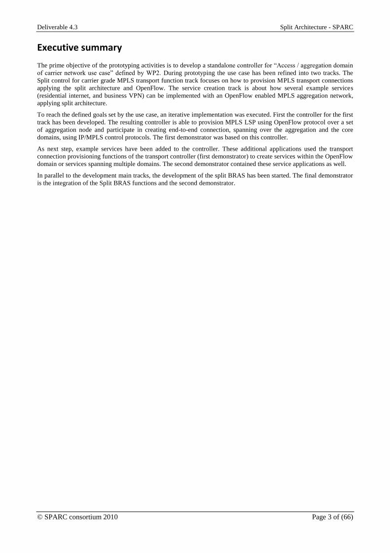
The prime objective of the prototyping activities is to develop a standalone controller for “Access / aggregation domain
of carrier network use case” defined by WP2. This document summarizes the design choices made during prototyping.
It also specifies how the functions to be implemented are decomposed into modules and presents the behavior of these
modules. The description of the functional elements follow the iterative implementation: first it discusses the MPLS
OpenFlow transport controller. Then the updates, which are undertaken during the second iteration, are detailed. Then
the third iteration, the integration of the centralized MPLS transport and service controller with split BRAS controller
and forwarder.

Deliverable 4.3 Split Architecture - SPARC
© SPARC consortium 2010 Page 2 of (66)
Disclaimer
This document contains material, which is the copyright of certain SPARC consortium parties, and may not
be reproduced or copied without permission.
In case of Public (PU):
All SPARC consortium parties have agreed to full publication of this document.
In case of Restricted to Programme (PP):
All SPARC consortium parties have agreed to make this document available on request to other framework
programme participants.
In case of Restricted to Group (RE):
All SPARC consortium parties have agreed to full publication of this document. However this document is
written for being used by <organisation / other project / company etc.> as <a contribution to standardization /
material for consideration in product development etc.>.
In case of Consortium confidential (CO):
The information contained in this document is the proprietary confidential information of the SPARC
consortium and may not be disclosed except in accordance with the consortium agreement.
The commercial use of any information contained in this document may require a license from the proprietor
of that information.
Neither the SPARC consortium as a whole, nor a certain party of the SPARC consortium warrant that the
information contained in this document is capable of use, nor that use of the information is free from risk,
and accepts no liability for loss or damage suffered by any person using this information.
Imprint
[Project title] Split Architecture
[short title] SPARC
[Number and title of work package] WP4 – Prototyping
[Document title] Description of the implemented architecture
[Editor] András Kern (ETH)
[Work package leader] Attila Takács (ETH)
[Task leader] András Kern (ETH)
Copyright notice
© 2008 Participants in project SPARC
Optionally list of organisations jointly holding the Copyright on this document
Deliverable 4.3 Split Architecture - SPARC
© SPARC consortium 2010 Page 3 of (66)
Executive summary
The prime objective of the prototyping activities is to develop a standalone controller for “Access / aggregation domain
of carrier network use case” defined by WP2. During prototyping the use case has been refined into two tracks. The
Split control for carrier grade MPLS transport function track focuses on how to provision MPLS transport connections
applying the split architecture and OpenFlow. The service creation track is about how several example services
(residential internet, and business VPN) can be implemented with an OpenFlow enabled MPLS aggregation network,
applying split architecture.
To reach the defined goals set by the use case, an iterative implementation was executed. First the controller for the first
track has been developed. The resulting controller is able to provision MPLS LSP using OpenFlow protocol over a set
of aggregation node and participate in creating end-to-end connection, spanning over the aggregation and the core
domains, using IP/MPLS control protocols. The first demonstrator was based on this controller.
As next step, example services have been added to the controller. These additional applications used the transport
connection provisioning functions of the transport controller (first demonstrator) to create services within the OpenFlow
domain or services spanning multiple domains. The second demonstrator contained these service applications as well.
In parallel to the development main tracks, the development of the split BRAS has been started. The final demonstrator
is the integration of the Split BRAS functions and the second demonstrator.

Deliverable 4.3 Split Architecture - SPARC
© SPARC consortium 2010 Page 4 of (66)
List of authors
Organization/Company Author
EAB Wolfgang John
ETH András Kern
EICT Andreas Köpsel
IBBT Sachin Sharma
ACREO Pontus Sköldström

Deliverable 4.3 Split Architecture - SPARC
© SPARC consortium 2010 Page 5 of (66)
Table of Contents
Disclaimer.......................................................................................................................................................... 2 Executive summary ........................................................................................................................................... 3 List of authors .................................................................................................................................................... 4 Table of Contents .............................................................................................................................................. 5 List of figures .................................................................................................................................................... 6 List of Tables ..................................................................................................................................................... 7 Abbreviations .................................................................................................................................................... 8 1 Introduction ................................................................................................................................................ 9
1.1 Project Context ..................................................................................................................................... 9 1.2 Relation with Other Work Packages .................................................................................................... 9 1.3 Scope of Deliverable ............................................................................................................................ 9
2 Prototyped Network Scenarios ................................................................................................................. 10 2.1 Split Control of Carrier Grade MPLS Transport Functions ............................................................... 11 2.2 Service Node Virtualization ............................................................................................................... 12
3 Interfaces and Associated Functionalities ................................................................................................ 13 3.1 Southbound Interface.......................................................................................................................... 13 3.2 Network-to-Network Interface ........................................................................................................... 13 3.3 User-to-Network Interface .................................................................................................................. 14 3.4 Northbound Interface.......................................................................................................................... 14
4 Enhanced OpenFlow MPLS Data Plane .................................................................................................. 15 4.1 Updates to the Ericsson MPLS OpenFlow Switch ............................................................................. 15 4.2 BFD based CC/CV and Protection Switching ................................................................................... 15 4.3 Virtualization system .......................................................................................................................... 18 4.4 Pseudo Wire emulation (PWE) .......................................................................................................... 19 4.5 Summary of forwarding plane extensions .......................................................................................... 21
5 MPLS OpenFlow Controller Architecture ............................................................................................... 22 5.1 NOX Controller Framework and Associated Tools ........................................................................... 22 5.2 Functional Decomposition and Controller Internal Interfaces ........................................................... 23 5.3 Graphical User Interface Proxy Component ...................................................................................... 24 5.4 Topology Discovery Components ...................................................................................................... 26 5.5 Transport Connection Manager Component ...................................................................................... 29 5.6 NNI Protocol Proxy ............................................................................................................................ 35 5.7 G2MPLS RSVP-TE Plug-in Component ........................................................................................... 42
6 Service Creation Applications .................................................................................................................. 44 6.1 Service Controller Architecture and Interfaces .................................................................................. 44 6.2 Generic Dynamic Service Component ............................................................................................... 45 6.3 DHCP Based Residential Service Component ................................................................................... 47 6.4 E-LINE Service Component ............................................................................................................... 49
7 “Floating BRAS” Integrated Prototype .................................................................................................... 52 7.1 Updated Control Plane Architecture .................................................................................................. 52 7.2 BRAS-Aware Datapath ...................................................................................................................... 53 7.3 Service Policing Components ............................................................................................................. 53 7.4 BRAS Architecture Overview ............................................................................................................ 55 7.5 Split BRAS Workflow ........................................................................................................................ 59
References ....................................................................................................................................................... 65

Deliverable 4.3 Split Architecture - SPARC
© SPARC consortium 2010 Page 6 of (66)
List of figures
Figure 1: Relation of SPARC work packages ................................................................................................... 9 Figure 2: Architecture of an Operators network (see section 2.2.1.1 of D2.1). ............................................... 10 Figure 3: Targeted network scenario ............................................................................................................... 11 Figure 4: Independent and integrated control of transport and service specific functions .............................. 12 Figure 5: The prototyped architecture, key elements and interfaces. .............................................................. 13 Figure 6: BFD implementation for OpenFlow version 1.1. ............................................................................. 17 Figure 7: Simplified diagram of the OAM implementation for OpenFlow 1.1 ............................................... 18 Figure 8: The parts of the virtualization system. ............................................................................................ 19 Figure 9: Outline of a PWE frame with sources for the different frame elements .......................................... 20 Figure 10: A common abstract model for all implementation is given. .......................................................... 22 Figure 11: Key functional modules and interfaces .......................................................................................... 23 Figure 12: Attaching Graphical User Interface to NOX controller ................................................................. 25 Figure 13: Screenshot depicting the graphical user interface application. ...................................................... 26 Figure 14: The NOX Routing Mechanism ...................................................................................................... 26 Figure 15: (A) NOX modified Mechanism (Spanning Tree solution) (B) without Spanning Tree Creation 27 Figure 16: Major building blocks and their relations of Transport Connection Manager ............................... 29 Figure 17: Main steps of reacting on a request ................................................................................................ 31 Figure 18: Flow manager procedures upon receiving a link state update (up/down) notification .................. 32 Figure 19: Steps for configuring 1-to-1 protected path pair. ........................................................................... 33 Figure 20: Multicast tree configuration steps. ................................................................................................. 34 Figure 21: Split architecture as it applied in Quagga ...................................................................................... 36 Figure 22: Integrating Quagga stack into NOX via implementing NNI protocol proxy. ................................ 37 Figure 23: Relaying the control packet through the port mapper .................................................................... 39 Figure 24: Interaction between modules in order to configure an end-to-end tunnel. ..................................... 41 Figure 25: Implemented controller software architecture ............................................................................... 42 Figure 26: Extending MPLS OpenFlow controller with service control components. ................................... 45 Figure 27: Binding services to be provisioned to customers ........................................................................... 46 Figure 28: UNI port states with major transitions. .......................................................................................... 47 Figure 29: Key functional elements of Residential Internet service module and their relation to surrounding
modules. .......................................................................................................................................................... 48 Figure 30: State machine representing the Service Instance Module for DHCP based residential internet
access component. ........................................................................................................................................... 48 Figure 31: VPWS Service application ............................................................................................................. 50 Figure 32: VPWS service creation states ........................................................................................................ 50 Figure 33: Split control for Floating BRAS. ................................................................................................... 52 Figure 34: BRAS-aware MPLS aggregation node structure in our prototype ................................................. 53 Figure 35: BRAS steering component. ............................................................................................................ 54 Figure 36: Split BRAS functional modules ..................................................................................................... 56 Figure 37: PPP session negotiation within the split BRAS ............................................................................. 61 Figure 38: IP routing and associated FlowMod generation ............................................................................. 64

Deliverable 4.3 Split Architecture - SPARC
© SPARC consortium 2010 Page 7 of (66)
List of Tables
Table 1. Summary of proposed, defined and implemented OpenFlow protocol extensions. .......................... 21 Table 2: Mapping configuration requests to flow managers ........................................................................... 30 Table 3: List of triggers sent to Domain Modeler and the given responses. ................................................... 38 Table 4: Experimenter PPPoE actions ............................................................................................................. 55

Deliverable 4.3 Split Architecture - SPARC
© SPARC consortium 2010 Page 8 of (66)
Abbreviations
SPARC Split Architecture VLAN Virtual Local Area Network
API Application Programming Interface VPLS Virtual Private LAN Service
ARP Address Resolution Protocol VPN Virtual Private Network
BFD Bidirectional Forward Detection VPWS Virtual Private Wire Service
BRAS Broadband Remote Access Service
CLI Command Line Interface
CPE Customer Premises Equipment
DHCP Dynamic Host Configuration Protocol
FEC Forwarding Equivalence Class
GMPLS Generalized Multiprotocol Label Switching
GUI Graphical User Interface
ILM Incoming Label Mapping
IWF Interworking Function
LDP Label Distribution Protocol
LFIB Label Forwarding Information Base
LLDP Link Layer Discovery Protocol
LSP Label Switched Path
MSAN Multiservice Access Node
MPLS Multiprotocol Label Switching
MPtP Multipoint to Point
NHLFE Next Hop Label Forwarding Entry
NNI Network-to-Network Interface
OAM Operation, Administration and Maintenance
ONF Open Networking Foundation
OSPF Open Shortest Path First
QoS Quality of Service
PPP Point-to-Point Protocol
PPPoE Point-to-Point Protocol over Ethernet
PtP Point-to-Point
RWG Residential Gateway
RIB Routing Information Base
RSVP-TE Resource Reservation Protocol with Traffic Engineering
SCP Service Creation Point
SDH Synchronous Digital Hierarchy
SDU Service Data Unit
UNI User-to-Network Interface

Deliverable 4.3 Split Architecture - SPARC
© SPARC consortium 2010 Page 9 of (66)
1 Introduction
1.1 Project Context
The project SPARC “Split architecture for carrier-grade networks” aims towards implementing a new split in the
architecture of Internet components. In order to better support network design and operation in large-scale networks
supporting millions of customers, high automation and high reliability, the project will investigate splitting the
traditionally monolithic IP router architecture into separable forwarding and control elements. The project will
implement a prototype of this architecture based on the OpenFlow concept and demonstrate the functionality at selected
international events with high industry awareness, e.g., the MPLS Congress.
The project, if successful, will open the field for new business opportunities by lowering the entry barriers present in
current components. It will build on OpenFlow and GMPLS technology as starting points, investigating if and how the
combination of the two can be extended and study how to integrate IP capabilities into operator networks emerging
from the data centre with simpler and standardized technologies.
1.2 Relation with Other Work Packages
Figure 1: Relation of SPARC work packages
In the “workflow” of the dedicated work packages of SPARC, WP2 sets the stage for the other technical work
packages, namely WP3 (Architecture), WP4 (Prototyping) and WP5 (Validation & Performance Evaluation). WP2 will
define use cases and requirements. Based on those use cases and additional generic requirements, an initial study for a
Split Architecture in relation to an enhanced version of OpenFlow will be done by WP3. In addition, this architecture
will be evaluated against certain architectural trade-offs. WP4 will implement a selected sub-set of the resulting
architecture, whose feasibility will be validated in WP5. WP6 will disseminate the result at international conferences
and publications. The schematic of the workflow is shown in Figure 1.
1.3 Scope of Deliverable
The prime objective of the prototyping activities is develop a standalone controller for “Access / aggregation domain of
carrier network use case” defined by WP2. This controller is part of the proof-of-concept demonstrator, where a
centralized domain controller manages an MPLS based aggregation domain, seamlessly inter-works with a legacy
distributed control plane of an IP/MPLS core network and participates in service creation.
This deliverable describes the implementation decisions undertaken during the prototyping activities and it presents the
resulting control architecture including the major configuration procedures. However, it does not detail either the switch
forwarding model extensions or the OpenFlow protocol extensions. The designed protocol extensions are reported in
Deliverable 4.2.
/ Scenarios
WP5 Validation & Performance
Evaluation
WP1 Project Management
WP3 Architecture
WP2 Use Case
s Business
WP4 Prototyping
WP5 Validation & Performance
Evaluation
WP6 Dissemination
WP1 Project Management

Deliverable 4.3 Split Architecture - SPARC
© SPARC consortium 2010 Page 10 of (66)
2 Prototyped Network Scenarios
The network scenario considered during prototyping is based on the “Access / aggregation domain of carrier network
use case” defined in section 2.2.1.1 of Deliverable 2.1. Such a network consists of three segments: the access, the
aggregation, and the backbone or core segments. Each segment makes use of different transport technologies. In
backbone IP/MPLS is the predominant packet transport technology. In access and aggregation segments, however,
several transport technologies can be observed, like Ethernet or SDH. The coexistence of multiple transport
technologies in a single network on one hand adds burden on the network management system. On the other hand, it
will fix the placements of service nodes that decrease the possibility of optimizing network resources for reaching better
network utilization and lower costs. For instance, the service node of residential internet service, the BRAS, is deployed
at the border of the aggregation and the core.
Figure 2: Architecture of an Operators network (see section 2.2.1.1 of D2.1).
The first step towards reaching the targeted level of flexibility in efficient service creation is the consolidation of
forwarding technologies in the access/aggregation to a common solution or very few ones. MPLS-based forwarding is a
good candidate in the aggregation since in the core the IP/MPLS, which obviously based on MPLS forwarding, is
mature. By transforming the aggregation to an MPLS based one the same forwarding method will be used at all parts of
the network (as it was also discussed in Seamless MPLS [2]). The other candidate for being the sole forwarding is the
most-widespread layer 3 technology. For any of the above cases, a unified control solution is a must. The logical choice
would be the GMPLS. While GMPLS can configure the MPLS forwarders in the aggregation domain, the seamless
interoperation with the core must be ensured. Peering GMPLS with IP/MPLS seems trivial; however, in GMPLS
several key message objects have been altered making direct communication between an IP/MPLS and a GMPLS
protocol speaker hard [25]. Updating the IP/MPLS core to GMPLS control is would increate the costs significantly
making the overall solution less promising. A much viable option is the Seamless MPLS concept, where all nodes in the
core as well as in the aggregation are IP/MPLS aware. This latter concept however expects that most nodes in the
aggregation implements the whole IP/MPLS stack of OSPF [9], LDP [10] and MP-BGP [12] increasing the CAPEX of
these elements. Furthermore, setting up such network is configuration intensive. This led us to apply split architecture in
this use case.
According to the work performed in the architecture working group of SPARC project (D3.2), the split architecture
concept, i.e., cutting forwarding and control functions, allows implementing such a scalable and control framework.
WP3 group reported several stages of integrating split architecture that are as follows:
1. Emulation of transport services: As a first step, OpenFlow may be introduced in transport domains (e.g.,
Ethernet, MPLS, optics, etc.) by replacing legacy network devices with OpenFlow-compliant datapath
elements and deploying a control plane that emulates behaviour of the legacy transport technology in use, e.g.,
an Ethernet domain, an MPLS domain, etc.
2. Enhanced emulation of transport services: For a carrier-grade Split Architecture, a number of mandatory
features and functions must be added to OpenFlow in order to fully comply with OAM requirements (among
others), resiliency and scalability needs. Again, all service nodes in this second integration scenario remain
unaltered.

Deliverable 4.3 Split Architecture - SPARC
© SPARC consortium 2010 Page 11 of (66)
3. Service node virtualization: Carrier-grade operator networks provide a number of functional elements, e.g.,
for authentication and authorization, service creation, enforcing quality of service, etc. Most of these functions
are today located on a limited set of network devices. A third integration level for split architecture is
virtualization of such service node functions.
4. All-OpenFlow-Network: Obviously, OpenFlow deployments may be pushed forward to other network
domains as well, e.g., for controlling residential gateways (RGW) in customer premises networks or toward the
operator’s core domain.
The following sections briefly set out the prototyping targets based on the above integration stages. Since the “all-
OpenFlow network” case have been considered out-of-scope during the architecture studies, the prototyping activities
adopted the first three integration stages only.
2.1 Split Control of Carrier Grade MPLS Transport Functions
By combining the first two stages, the first prototyping target can be easily formulated: implement a split architecture
based control solution for OpenFlow capable carrier-grade MPLS based aggregation networks. Among the carrier-grade
functionalities, we focused on “Standardized Services”, “Scalability”, “Reliability” and “Service Management” aspects.
The “Quality of Service” aspect was excluded from prototyping during the first year due to timing reasons: the
development of transport functions happened in parallel to the architecture discussions. D3.2 identified some missing
and limited OpenFlow features required for implementing QoS; however, the ONF also addressed these limitations and
defined standard solution. Therefore, the project decided to concentrate on prototyping service creation functions.
The OpenFlow capable switches are expected to be introduced during network upgrades rather than part of a green-field
project, so we can make several further assumptions:
1. The core network segment will remain as it is today, an IP/MPLS network running its own distributed control
plane; and
2. MPLS forwarding plane is deployed in the aggregation domain in order to make possible to establish transport
tunnels between any two nodes of the network.
Video
WEB
Client
M PLS
CP
M PLS
CP
M PLS
CP
OFSwitch
OFSwitch
OFSwitch
OFSwitch
OFEdge
OFEdge
IP/M PLS c o r eOPENFLOW M PLS Ag g r eg a t io n
NNI
OSPF, LDP
RSVP-TE, BGP
OFSwitch
CoreMPLS
CoreMPLS
CoreMPLS
Ser v ic esCl ien t s
Client
c t r lc t r l
NOX + M PLS su ppo r t
OF
Do
ma
in
MG
MT
NN
I
Pr
ot
oc
ol
Pr
ox
y
UN
I Tr
igg
er
Pr
oc
es
so
r
Vir t u a l IF
Qu
ag
ga
OS
PF
Qu
ag
ga
LD
P
VideoVideoVideo
WEBWEBWEB
ClientClient
M PLS
CP
M PLS
CP
M PLS
CP
OFSwitch
OFSwitch
OFSwitch
OFSwitch
OFSwitch
OFSwitch
OFSwitch
OFSwitch
OFSwitch
OFSwitch
OFSwitch
OFSwitch
OFEdgeOF
EdgeOF
Edge
OFEdgeOF
EdgeOF
Edge
IP/M PLS c o r eOPENFLOW M PLS Ag g r eg a t io n
NNI
OSPF, LDP
RSVP-TE, BGP
OFSwitch
OFSwitch
OFSwitch
CoreMPLSCore
MPLSCore
MPLS
CoreMPLSCore
MPLSCore
MPLSCore
MPLSCore
MPLSCore
MPLS
Ser v ic esCl ien t s
ClientClient
c t r lc t r l
NOX + M PLS su ppo r t
OF
Do
ma
in
MG
MT
NN
I
Pr
ot
oc
ol
Pr
ox
y
UN
I Tr
igg
er
Pr
oc
es
so
r
Vir t u a l IF
Qu
ag
ga
OS
PF
Qu
ag
ga
LD
P
c t r lc t r l
NOX + M PLS su ppo r t
OF
Do
ma
in
MG
MT
NN
I
Pr
ot
oc
ol
Pr
ox
y
UN
I Tr
igg
er
Pr
oc
es
so
r
Vir t u a l IF
Qu
ag
ga
OS
PF
Qu
ag
ga
LD
P
Figure 3: Targeted network scenario
The network scenario derived from the above assumptions and design choices is depicted in Figure 3. The network
comprises of two major domains: an IP/MPLS core domain running its distributed control plane; and an MPLS
aggregation managed by a federation of centralized domain controllers. 1. This latter means that the aggregation domain
has been split to topologically disjoint sub-domains and each sub-domain is managed by a single controller. Each of the
domain controllers configures its own aggregation domain making use of the OpenFlow protocol and communicates
with the IP/MPLS core and with all other domain controllers using the IP/MPLS control protocols: like OSPF, LDP and
RSVP-TE. Using already deployed control protocols between the different domains eliminates the need of upgrading
the IP/MPLS core routers.
The implementation of service interfaces towards end users (User-to-Network Interface, UNI) and different servers is
out-of-scope of this phase. But a simple service configuration function is to be added for demonstration purposes.

Deliverable 4.3 Split Architecture - SPARC
© SPARC consortium 2010 Page 12 of (66)
2.2 Service Node Virtualization
The SPARC architecture extends virtualization of transport domains through the concept of service node virtualization.
Service nodes provide additional services beyond plain transport such as user access control, QoS and policy
enforcement for triple-play services, etc. Making service nodes virtual entails a number of changes to a carrier grade
split architecture including advanced openness and extensibility on the data path elements in order to provide more
generic processing capabilities (this is required e.g. for additional protocol adaptation functionality). The need to
interact with legacy network deployments and protocol stacks raises the question how to structure a split architecture
control plane in an efficient manner. Virtualization of service nodes enables network operators to deploy a specific
functionality at various locations in a network. A virtualized service node and the underlying virtualized (MPLS based)
transport domain may interact in order to provide a flexible service creation based on operator needs.
Introducing split architecture based control of MPLS transport functions, like forwarding, protection and OAM, adds
flexibility to service creation. It allows establishing transport connectivity between the service nodes regardless where
they are actually deployed. The controller can also connect the individual end users to the service nodes one-by-one
making load balancing between the service nodes possible. One example of such service node virtualization considered
during prototyping is the Broadband Remote Access Server, BRAS. It is responsible for managing the end user’s
residential internet services, which includes terminating PPPoE tunnels. A network domain controller supports a
virtualized BRAS service node by creating MPLS based Ethernet services (E-LINE, E-LAN services) between the end
users and the BRAS instances as well as between the BRASs and the remote servers. The internals of the provided user
services, for instance user authentication, is out of scope of the network domain controller. These functions are
implemented by a standalone BRAS control function either integrated into the BRAS service node or via a dedicated
split controller.
Ne
two
rk D
om
ain
Co
ntro
llerCTRL kernel (NOX)
MPLS Transport Application
L2 VPN Control APP L3 VPN Control APP
BRAS manager (maps users to different BRASs)
Video
WEB
OFSwitch
OFSwitch
OFSwitch
OFSwitch
OFEdge
OFSwitch
Client
Client
BRAS
OFEdge
BRAS
CoreMPLS
CoreMPLS
Pro
toco
l Pro
xy
Ne
two
rk D
om
ain
Co
ntro
llerCTRL kernel (NOX)
MPLS Transport Application
L2 VPN Control APP L3 VPN Control APP
BRAS manager (maps users to different BRASs)
VideoVideoVideo
WEBWEBWEB
OFSwitch
OFSwitch
OFSwitch
OFSwitch
OFSwitch
OFSwitch
OFSwitch
OFSwitch
OFSwitch
OFSwitch
OFSwitch
OFSwitch
OFEdgeOF
EdgeOF
Edge
OFSwitch
OFSwitch
OFSwitch
ClientClient
ClientClient
BRASBRASBRAS
OFEdgeOF
EdgeOF
Edge
BRASBRASBRAS
CoreMPLSCoreMPLSCoreMPLS
CoreMPLSCoreMPLSCoreMPLS
Pro
toco
l Pro
xy
Ne
two
rk D
om
ain
Co
ntro
llerCTRL kernel (NOX)
MPLS Transport Application
L2 VPN Control APP L3 VPN Control APP
DHCP based Residential Internet APP
Video
WEB
OFSwitch
OFSwitch
OFSwitch
OFSwitch
OFEdge
OFSwitch
Client
Client
OFEdge
CoreMPLS
CoreMPLS
Pro
toc
ol P
rox
y
Ne
two
rk D
om
ain
Co
ntro
llerCTRL kernel (NOX)
MPLS Transport Application
L2 VPN Control APP L3 VPN Control APP
DHCP based Residential Internet APP
VideoVideoVideo
WEBWEBWEB
OFSwitch
OFSwitch
OFSwitch
OFSwitch
OFSwitch
OFSwitch
OFSwitch
OFSwitch
OFSwitch
OFSwitch
OFSwitch
OFSwitch
OFEdgeOF
EdgeOF
Edge
OFSwitch
OFSwitch
OFSwitch
ClientClient
ClientClient
OFEdgeOF
EdgeOF
EdgeCore
MPLSCore
MPLSCore
MPLSCore
MPLSCore
MPLSCore
MPLS
Pro
toc
ol P
rox
y
Figure 4: Independent and integrated control of transport and service specific functions
A further step is when all user session related control functions are fully integrated into the network domain
controller.
Deliverable 4.3 Split Architecture - SPARC
© SPARC consortium 2010 Page 13 of (66)
3 Interfaces and Associated Functionalities
Our previous deliverable, the D3.2, suggested a split architecture framework for carrier grade networks. As most control
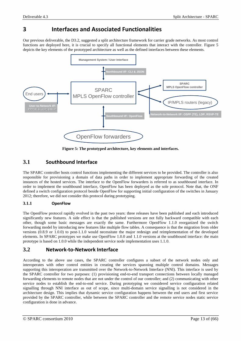
functions are deployed here, it is crucial to specify all functional elements that interact with the controller. Figure 5
depicts the key elements of the prototyped architecture as well as the defined interfaces between these elements.
Southbound I/F: OpenFlowNetwork-to-Network I/F: OSPF (TE), LDP, RSVP-TE
Northbound I/F: CLI & JSON
User-to-Network I/F:
PPPoE & LCP, DHCPPPPoE & LCP, DHCP
SPARC
MPLS OpenFlow controller
OpenFlow forwarders
SPARC
MPLS OpenFlow controller
IP/MPLS routers (legacy)
End users
Management System / User Interface
Figure 5: The prototyped architecture, key elements and interfaces.
3.1 Southbound Interface
The SPARC controller hosts control functions implementing the different services to be provided. The controller is also
responsible for provisioning a domain of data paths in order to implement appropriate forwarding of the created
instances of the hosted services. The interface to the OpenFlow forwarders is referred to as southbound interface. In
order to implement the southbound interface, OpenFlow has been deployed as the sole protocol. Note that, the ONF
defined a switch configuration protocol beside OpenFlow for supporting initial configuration of the switches in January
2012; therefore, we did not consider this protocol during prototyping.
3.1.1 OpenFlow
The OpenFlow protocol rapidly evolved in the past two years: three releases have been published and each introduced
significantly new features. A side effect is that the published versions are not fully backward compatible with each
other, though some basic messages are exactly the same. Furthermore OpenFlow 1.1.0 reorganized the switch
forwarding model by introducing new features like multiple flow tables. A consequence is that the migration from older
versions (0.8.9 or 1.0.0) to post-1.1.0 would necessitate the major redesign and reimplementation of the developed
elements. In SPARC prototypes we make use OpenFlow 1.0.0 and 1.1.0 versions at the southbound interface: the main
prototype is based on 1.0.0 while the independent service node implementation uses 1.1.0.
3.2 Network-to-Network Interface
According to the above use cases, the SPARC controller configures a subset of the network nodes only and
interoperates with other control entities in creating the services spanning multiple control domains. Messages
supporting this interoperation are transmitted over the Network-to-Network Interface (NNI). This interface is used by
the SPARC controller for two purposes: (1) provisioning end-to-end transport connections between locally managed
forwarding elements to remote nodes that are not under the control of our controller; and (2) communicating with other
service nodes to establish the end-to-end service. During prototyping we considered service configuration related
signalling through NNI interface as out of scope, since multi-domain service signalling is not considered in the
architecture design. This implies that dynamic service configuration happens between the end users and first service
provided by the SPARC controller, while between the SPARC controller and the remote service nodes static service
configuration is done in advance.

Deliverable 4.3 Split Architecture - SPARC
© SPARC consortium 2010 Page 14 of (66)
3.2.1 IP/MPLS Control Protocols
Our assumptions imply that the distributed IP/MPLS control plane will remain untouched in the operator’s core network
and the, thus, the controller must be able to interact with IP/MPLS control plane elements. In order to fulfil this
requirement, the implemented SPARC OpenFlow controller must be an IP/MPLS control plane element, or protocol
speaker. The IP/MPLS control plane comprises of several protocols. The Open Shortest Path First (OSPF) [9] protocol
ensures that all protocol speakers share the topology database, while with Traffic Engineering extensions the protocol
allows sharing TE information. An alternative to OSPF is the Intermediate System to Intermediate System (ISIS)
protocol. Beside that, a signalling protocol is essential to provision MPLS tunnels. For this latter task, two three
protocols are wide-spread: Label Distribution Protocol (LDP) [10], Resource Reservation Protocol - Traffic
Engineering (RSVP-TE) [11] and Multiprotocol Border Gateway Protocol (MP-BGP) [12]. These protocols are used for
different roles in an operators’ network: LDP and RSVP-TE are for configuring MPLS transport connections, the MP-
BGP serves a service configuration tool (e.g., L3 VPNs or VPLS) or transport tunnel configuration when the network is
covered by multiple OSPF/ISIS areas.
During prototyping the configuration of service nodes in the core are considered to be static (or network management
dictated). This means that node no service signalling protocols were considered, only transport tunnel setting ones:
OSPF, LDP, RSVP-TE and MP-BGP. The IP/MPLS protocol speakers can be organized into one or several OSPF areas
that solution improves scalability, but makes the network configuration more complex, since the accurate topology
information is distributed only within an OSPF area. For simplicity reasons we considered that all IP/MPLS protocol
speakers are covered by a single OSPF area. This means that MP-BGP is not needed in the prototype. To sum up, the
following IP/MPLS control protocols will run over the NNI interface: OSPF, LDP and RSVP-TE.
3.3 User-to-Network Interface
In the operator networks’ context, the controller hosted services are typically configured upon client user requests. For
instance, after enabling a residential internet service to an end user, this user can request the instantiation of that service.
In other word the user sends a configuration request to the service control function and receives configuration response.
Such communication exchanges are implemented over a user-to-network interface (UNI). The provided service mix
determines what protocols must be implemented over this interface.
3.3.1 PPPoE & PPP
During prototyping we detailed one single service: the residential internet service. One widely deployed solution
defines a direct point-to-point tunnel between the end user and the Broadband Residential Access Node (BRAS). The
tunnel is implemented using the PPP protocol, while the PPPoE protocol is used to encapsulate the PPP stream into
Ethernet packets. Both, PPPoE and PPP implement control features. Therefore, the controller, when it implements
BRAS-like functionalities, will be able to handle these protocols as well.
3.3.2 DHCP
An alternative implementation of the residential internet service omits the PPP layer and the users’ packets are
encapsulated into Ethernet. Then the end host is configured with DHCP protocol. Therefore, DHCP is also expected on
the User-to-Network interface.
3.4 Northbound Interface
The controller shall provide a northbound interface to the network operator or to its management system. A full-fledged
northbound interface was not yet described during prototyping; therefore, a simplified interface is defined with the
purpose of supporting prototype demonstrations. The interface is implemented by two protocols: a command line
interface and a generic interface toward a graphical user interface. This latter interface allows passing the controller
formulated messages encoded with JavaScript Object Notation. The structure and the content of the messages are
specified by the graphical user interface (see section 5.3 for details).

Deliverable 4.3 Split Architecture - SPARC
© SPARC consortium 2010 Page 15 of (66)
4 Enhanced OpenFlow MPLS Data Plane
The SPARC project objectives showed that the control plane aspects and the fast prototyping of missing functions are in
focus but the aspect of high data plane throughput is not of highest priority within the project. Therefore, we decided to
use a software switch implementation and excluded any data plane hardware implementations. Among the software
implementations we took into account Stanford’s reference implementation [13] and OpenVSwitch [14].
Considering the targeted network scenario, we adopted an extended version of the Stanford reference switch
implementation which adds MPLS support to the switch. This was already in development by Ericsson [15]. It provided
MPLS label handling capabilities while other software implementation available at that time did not. Additionally,
OpenVSwitch is a more complex system and is making upgrades much more resource consuming compared to the
simpler Stanford implementation.
The Ericsson enhanced Stanford reference switch (which originally supported version 0.8.9 of the OpenFlow protocol)
had been upgraded by introducing MPLS support through new matching fields, flow entry actions and a Virtual Port
model able to act as an MPLS tunnel entry point. The original data plane has been further extended primarily in order
to demonstrate carrier grade functionality like sub-50ms restoration and business services. During the project the
Stanford reference switch was upgraded to support OpenFlow version 1.1, this release was used as a basis for a flexible
virtualization system and an improved restoration design.
4.1 Updates to the Ericsson MPLS OpenFlow Switch
Early in the project Stanford released a reference software switch with support for the OpenFlow v1.0 protocol. In order
to make use of the new features it supported we adapted the Ericsson enhancements from the 0.8.9 version as well as
made additional minor changes to the switch. One large issue was inconsistencies in the length of fields distinguishing
ports, which was a mixture of 16-bit and 32-bit integers; this was aligned to consistently use 32-bit identifiers.
4.2 BFD based CC/CV and Protection Switching
In order to support low-latency protection switching, a requirement for carrier-grade transport networks, support for
running Bi-directional Forwarding Detection (BFD) [16] has been added to the OpenFlow data plane. The
implementation supports basic BFD functionality for MPLS and is based on a draft version of RFC 6428 [17] which
adopts BFD for MPLS transport profile. The implementation supports two OAM features:
Continuity check (CC) – monitoring an LSP for loss of continuity;
Connection verification (CV) – verifying that the packets arrive at the intended destination.
Beside the above OAM functions the current implementation also supports protection switching apparatus, as the
OpenFlow 1.0 switch model lacks that feature.
The need for executing these OAM functions in the actual switch and not on the central controller is described in more
detail in section 10.3 of deliverable D3.1; a brief explanation is that it is the only way to make sure the correct data
plane links are monitored (without including the control plane links between the switches and the controller) as well as
meeting the timing requirements on rectifying a detected error within 50 ms.
4.2.1 Implementation for the Ericsson MPLS OpenFlow version 1.0 switch
The implemented BFD functions are able to monitor the forwarding status of an MPLS LSP and quickly (<30 ms)
detect if an LSP is not forwarding packets correctly due to a failed network interface, a broken link, a misconfiguration
etc. If the BFD session detects a failure, a protection switching module is immediately triggered which redirects the
affected traffic to a pre-configured backup LSP. Once the time-critical events (failure detection and failover switching)
have been handled the controller is notified both about the failure event and if the data plane was able to execute the
failover (e.g. the backup LSP could be broken as well).
The implementation can be sub-divided into three major parts, 1) the failover mechanism, 2) the notification
mechanism, and 3) the BFD implementation.
When triggered, the protection switching model iterates through the flow table looking for entries that use the
monitored virtual port in an Outport action. Any found entries are updated with the pre-configured backup virtual port
and in that way redirecting traffic to the working path. Note that these virtual ports typically implement MPLS LSP
tunnel ingress points.
The notification mechanism is an extension of the standard error message. An additional error type has been added
(called NOTIFICATION) which in turn can contain different types of sub-messages. With this mechanism we can
signal that, for example “LSP A has lost connectivity” or “failover from LSP A to LSP B was successful”.

Deliverable 4.3 Split Architecture - SPARC
© SPARC consortium 2010 Page 16 of (66)
The BFD implementation itself needed larger additions, the important parts being:
Active Virtual Ports: Previous virtual ports (designed for the Ericsson MPLS extensions of OpenFlow 0.8.9)
could only act as packet filters; they could modify incoming packets but not generate packets on their own. In
order to generate packets at a switch a new type of virtual port was introduced. In the BFD implementation
they are used to generate BFD control packets.
Passive Virtual Ports: One passive virtual port was added. This virtual port receives BFD control packet
templates that have not yet been assigned to any particular BFD session. It then modifies them by setting the
identifiers and values that defines a particular BFD session.
Group: The group allows you to define a group of action sets (called buckets). A group may be of several
types, e.g. multi-cast, random, etc. and it contains a number of buckets. A bucket in turn contains a number of
actions, for example, modify a field and send the packet to a port. Depending on the type of group the
incoming packet reaches it will be either send to e.g. all the buckets or one chosen randomly. The actions in
that group are then executed. In the BFD implementation the groups are used to multiply incoming BFD
control packets into passive virtual ports that assign them to a particular BFD session. This makes it possible to
reduce the amount of packets that have to be generated since sessions using the same timer values can share a
single packet generator instead of having one generator per BFD session.
Modified MPLS processing: In order to distinguish OAM packets from normal customer traffic packets the
Generic Associated Channel is used [18]. This adds additional processing steps to the basic MPLS functions
such as Label Swap and Label Pop.
BFD core implementation: The core of the implementation deals with managing a number of timers and state
variables, per BFD session. It is also responsible for keeping track of when it is appropriate to perform a
failover, e.g. some sessions may be configured with failover reversion, meaning that if the original working
path becomes operational after a failure it should once again be established as the working path.
In order to enable monitoring and protection for an LSP, several configuration messages have to be sent in order to
configure the various parts of the implementation. These messages and the configuration procedures are detailed in
Section 3.5 of SPARC deliverable 4.2.
4.2.2 Implementation for OpenFlow version 1.1
The implementation described above was originally designed for the 1.0 version of the Ericsson extended OpenFlow
protocol and datapath model. With the release of the 1.1 version, the BFD implementation was updated to make use of
the new mechanisms available in the new version. Version 1.1 introduced the concept of “Fast Failover” groups. These
groups contain buckets with references to either other groups or ports. When a Fast Failover group receives a packet, it
will transmit the packet to the first of these references which is alive. The state of a port or group is determined by a
status flag that is set by an external entity.
The new Fast Failover mechanism allows for a less invasive design, since it is no longer necessary to modify the
FlowTable itself in order to perform the protection switching. This allowed us to design a more generic model which
required fewer modifications of the data plane as well as the protocol itself. With the failover mechanism already in
place we can move a large part of the BFD functionality into an external module and put a more generic OAM structure
in place that could be reused for other OAM protocols apart from BFD.
In the 1.1 version, OAM packets (in this case: BFD packets) are created entirely by an external OAM process which
sends them to the OpenFlow software switch using a data channel. In our case we are using UNIX sockets as a fast and
simple means do transport the packets between the processes but other channels such as UDP/IP or shared memory
could be used. When an OAM packet arrives on a data channel, the switch forwards the packet directly into a group for
processing, bypassing the normal packet pipeline that does packet classification and FlowTable processing. When an
OAM packet enters a group it is treated exactly like any packet that has gone through the normal pipeline and from that
point shares fate with the normal data packets.
When OAM packets are received by the switch, the same modified MPLS processing that was used in the 1.0 version is
applied, but instead of sending the packet for internal processing in the software switch, it is forwarded to the external
OAM module with is responsible for decoding and associating it with a particular OAM session.
In case of failure, the external OAM module uses a control channel to update the state of the affected group, which will
cause traffic to switch to a different path in the Fast Failover group (in case one is available). During a failure, the same
notification mechanism is used as in the implementation for OpenFlow version 1.0; however, since all OAM session
information is in the external module, the notification to the controller only contains the new state and the group
number.
Deliverable 4.3 Split Architecture - SPARC
© SPARC consortium 2010 Page 17 of (66)
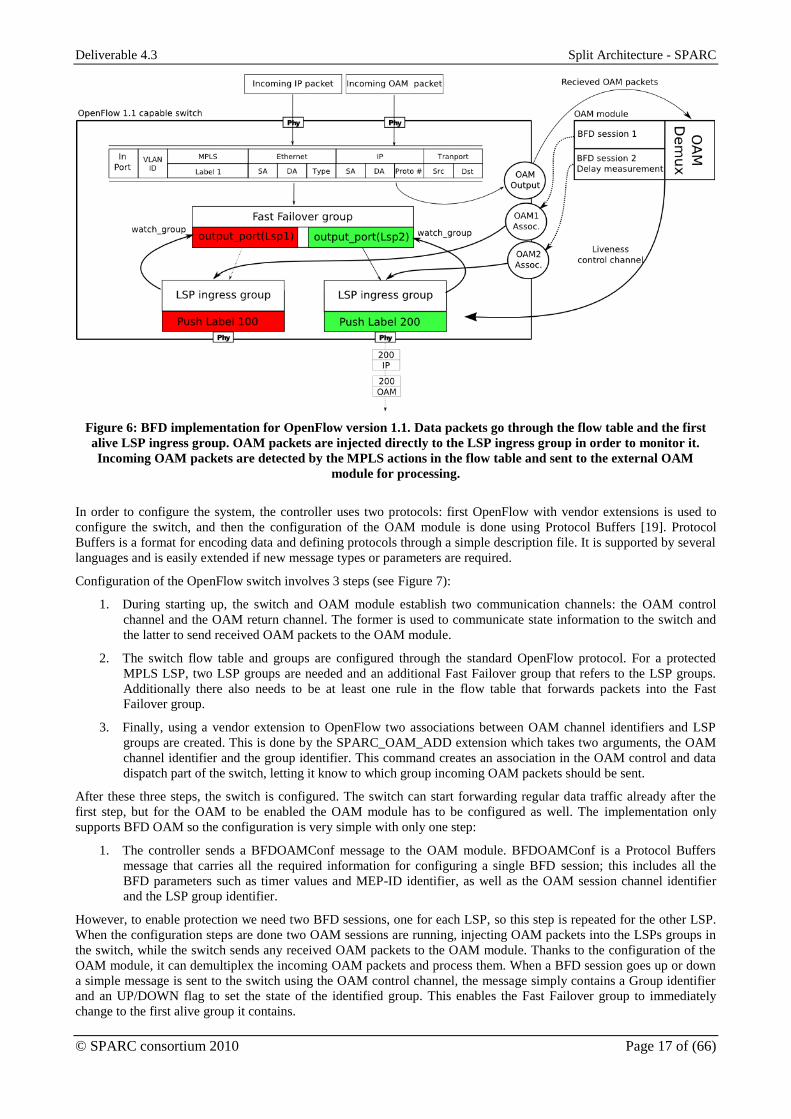
Figure 6: BFD implementation for OpenFlow version 1.1. Data packets go through the flow table and the first
alive LSP ingress group. OAM packets are injected directly to the LSP ingress group in order to monitor it.
Incoming OAM packets are detected by the MPLS actions in the flow table and sent to the external OAM
module for processing.
In order to configure the system, the controller uses two protocols: first OpenFlow with vendor extensions is used to
configure the switch, and then the configuration of the OAM module is done using Protocol Buffers [19]. Protocol
Buffers is a format for encoding data and defining protocols through a simple description file. It is supported by several
languages and is easily extended if new message types or parameters are required.
Configuration of the OpenFlow switch involves 3 steps (see Figure 7):
1. During starting up, the switch and OAM module establish two communication channels: the OAM control
channel and the OAM return channel. The former is used to communicate state information to the switch and
the latter to send received OAM packets to the OAM module.
2. The switch flow table and groups are configured through the standard OpenFlow protocol. For a protected
MPLS LSP, two LSP groups are needed and an additional Fast Failover group that refers to the LSP groups.
Additionally there also needs to be at least one rule in the flow table that forwards packets into the Fast
Failover group.
3. Finally, using a vendor extension to OpenFlow two associations between OAM channel identifiers and LSP
groups are created. This is done by the SPARC_OAM_ADD extension which takes two arguments, the OAM
channel identifier and the group identifier. This command creates an association in the OAM control and data
dispatch part of the switch, letting it know to which group incoming OAM packets should be sent.
After these three steps, the switch is configured. The switch can start forwarding regular data traffic already after the
first step, but for the OAM to be enabled the OAM module has to be configured as well. The implementation only
supports BFD OAM so the configuration is very simple with only one step:
1. The controller sends a BFDOAMConf message to the OAM module. BFDOAMConf is a Protocol Buffers
message that carries all the required information for configuring a single BFD session; this includes all the
BFD parameters such as timer values and MEP-ID identifier, as well as the OAM session channel identifier
and the LSP group identifier.
However, to enable protection we need two BFD sessions, one for each LSP, so this step is repeated for the other LSP.
When the configuration steps are done two OAM sessions are running, injecting OAM packets into the LSPs groups in
the switch, while the switch sends any received OAM packets to the OAM module. Thanks to the configuration of the
OAM module, it can demultiplex the incoming OAM packets and process them. When a BFD session goes up or down
a simple message is sent to the switch using the OAM control channel, the message simply contains a Group identifier
and an UP/DOWN flag to set the state of the identified group. This enables the Fast Failover group to immediately
change to the first alive group it contains.

Deliverable 4.3 Split Architecture - SPARC
© SPARC consortium 2010 Page 18 of (66)
Figure 7: Simplified diagram of the OAM implementation for OpenFlow 1.1
4.3 Virtualization system
The virtualization system required four extensions to the OpenFlow switch, one new and fairly complicated part, the
translation unit, and three simple extensions: one additional message for identifying the connecting controller during
OpenFlow protocol establishment, one vendor action called “Port translation”, and one message to configure the
translation unit. In order to explain the functionality of these extensions we start with a short reiteration of how the
virtualization system operates. This is described in more detailed in SPARC deliverable D3.3.
A virtualized switch (depicted in Figure 8) has several parts:
A virtualization table: this table is responsible for classifying incoming packets and determining to which
virtual network the packets belong to. It can do this in two ways, by examining only the incoming port of a
packet, and by examining both the incoming port and the VLAN tag of a packet. If a port is reserved for a
single virtual network the port number, it is enough to determine which virtual network the packet belongs to.
However, if the port is shared between multiple virtual networks an additional identifier is necessary, the
VLAN identifier. Once it has been determined which virtual network a packet belongs to, it is sent to the
particular flow tables reserved for that virtual network. In case the packet entered on a shared port the VLAN
tag is removed before the packet is forwarded. In the virtualization table additional actions could be performed
as well, if supported by the switch, such as applying rate limiting to incoming packets.
A set of customer tables: every virtual network has a number of flow tables reserved for its use. In these flow
tables a customer may install any kind of flow table entries. However, the number of flow tables available is
reduced since they are split among all virtual networks.
Customer groups: if the customer wishes to use groups in its processing pipeline all group types are available.
However, the number of groups available is reduced since they are split among all the virtual networks.
Virtualization groups: these groups perform the opposite function of the virtualization table. If the packet is
leaving the switch on a shared port they reapply the VLAN tag identifying the virtual network they belong to
before transmitting the packet. In the case of a reserved virtualization port they simple forward the packet to
the port. If the switch supports it they can also be used to apply additional actions, such as rate limiting or
priority marking.
Translation unit: this unit is responsible for making sure that customer flow tables and groups are isolated from
each other and from the virtualization table and groups. This is done by translating the commands sent to and
from customer controllers, making sure that the controller does not see anything it should not be able to see as
well as not being able to affect any parts that it should not be able to.

Deliverable 4.3 Split Architecture - SPARC
© SPARC consortium 2010 Page 19 of (66)
Figure 8: The parts of the virtualization system. The parts in dashed lines are new features.
Configuration of the virtualization tables and groups are handled entirely by the Master Controller (or rather, an
application running on it) using the standard OpenFlow protocol. The Master Controller also configures the Translation
unit using an OpenFlow vendor extension called SPARC_ADD_VN. This command has arguments detailing how a
virtual network should be implemented by a single switch, such as:
Virtual network identifier – A unique number identifying the network
Link tag identifier – Identifier for the encapsulation used on shared links, e.g. a VLAN ID
Table range – Range of flow tables reserved for the virtual network
Outgoing queue identifier – Identifier for the outgoing port queues reserved for the virtual network
Shared and customer port lists – Ports accessible by the virtual network and if they are shared or not
The translation unit uses the information provided by the SPARC_ADD_VN command to translate and restrict all the
OpenFlow messages depending on which (virtual network) controller the message is coming from or headed to. This is
implemented through a number of functions that translate e.g. port numbers from the physical domain into a virtual
domain, depending on a virtual network identifier. Additional functions translate e.g. virtual port identifiers to
virtualization groups. These are used to replace any “outport” action sent from a customer controller with a “goto
group” action. Various functions like this have been inserted into the OpenFlow software switch in the part of the
software that is responsible for parsing and constructing OpenFlow messages.
The “Port translation” vendor action mentioned earlier is required for performing protection switching outside of the
virtualized flow tables. For example, a customer may expect traffic to enter on what it believes is port 1 of a switch, and
program its flow tables accordingly. From the masters point of view this port may be something else such as port 4 or a
tunnel end-point, but this is hidden from the customer by the translation unit. However, in the case of protection
switching the incoming port may change depending on which path is used. So if a failure occurs the physical port may
change and the rules the customer has installed will be matching the wrong incoming port number, which may lead to
dropped traffic or traffic matching an unintended rule. Since the translation unit operates on the protocol level rather
than in the fast-path this has to be taken care of in the fast-path by the master controller applying the “port translation”
action on traffic that arrives over the backup path, hiding the failure from the customer view.
4.4 Pseudo Wire emulation (PWE)
Pseudo Wire emulation (PWE) is a mechanism for emulating point-to-point connections over packet switched networks
(PSN). In order to transport Layer 1, Layer 2 or Layer 3 signals over a PSN, PWE defines several layers. The payload
encapsulation maps the client data signal to a sequence of packets and is responsible for carrying any information
required to properly regenerate the carried signal at the remote endpoint. The Pseudo Wire (PW) demultiplexing layer
attaches an identifier (or label) to each packet. Then all packets extended with PW labels are encapsulated into the PSN
defined transport connection. Although PWE allows carrying different client signals over a PSN, e.g., ATM, TDM, and
Ethernet, we focused on the support of Ethernet packets only.

Deliverable 4.3 Split Architecture - SPARC
© SPARC consortium 2010 Page 20 of (66)
We have designed and implemented basic support for MPLS Pseudo Wire Emulation according to RFC3985 [20] and
RFC4385 [21], for OpenFlow version 1.0 with Ericsson MPLS extensions and OpenFlow version 1.1. This
implementation makes it possible to tunnel Ethernet frames transparently through an MPLS transport network.
4.4.1 Ethernet over MPLS pseudo wire processing
The first step when tunnelling an Ethernet frame in MPLS PWE is to strip the preamble and the Frame Check Sequence
of the Ethernet header, while leaving the other fields - such as destination and source addresses, EtherType and the
payload - in the packet. Then, if necessary, a PWE control word is prepended to the original packet. This control word
is used in various optional features, for example to support ordered delivery of tunnelled frames. This is not necessary
when encapsulating Ethernet frames as Ethernet does not require ordered delivery; therefore the control word can be
filled with zeros. The control word may also be omitted in case of Ethernet payload. The PWE label, identical to a
regular MPLS label, is then added to carry the PWE demultiplexer value. Finally the packet is encapsulated in an MPLS
transport tunnel by adding an additional MPLS label.
At egress side the MPLS transport label is removed. The remaining PWE label identifies which PW entity that will
further process the packet. After receiving the packet the PW entity removes the PWE label and processes the control
word. If everything is fine the payload is passed to appropriate networks service processing unit or to a port.
Figure 9: Outline of a PWE frame with sources for the different frame elements
4.4.2 OpenFlow pseudo wire processing
Implementation in OpenFlow version 1.0 with Ericsson MPLS extensions
The procedures described above have been implemented through vendor actions. Pairs of actions are assigned to each
step and the first member of each pair is used at the ingress side (for encapsulation) while the second one is applied at
the egress (for decapsulation).
At the ingress side, the first step is to reinterpret the just processed Ethernet packet as payload. The action, called
“payloadize”, treats the packet as payload and builds an encapsulating Ethernet header by inserting a new Ethernet
header around the original frame. The parameters of the payload action contain the source and destination MAC
addresses as well as the EtherType for the new Ethernet header.
The second required action is the “push control word” action that adds the control word after the Ethernet header. This
action could be extended with optional argument if support for more PWE features is implemented. After the control
word is added the PWE MPLS label needs to be pushed to the buffer, which can be done using the existing MPLS push
action. The frame is now a standard compliant MPLS PWE frame and may be handled as any other MPLS frame. Both
of the above mentioned actions are used in the ingress side of the PWE tunnel.
At the egress side, the counterparts of the “payloadize” and the “push control word” actions must be implemented.
However, the processing methods associated to the control word depend on the pseudo wire type; therefore both these
functions are implemented in a single “packetize” action. The parameters to the “packetize” action depends on what
functionality it implements. For instance, in case of Ethernet PWE it may have a parameter that indicates whether a
control word is expected on the stack or not and additional parameters may enable/disable control word processing.
The implemented “packetize” action assumes that a control word is present but it does not processes it. After removing
the control word it removes the encapsulating Ethernet header.

Deliverable 4.3 Split Architecture - SPARC
© SPARC consortium 2010 Page 21 of (66)
Implementation in OpenFlow version 1.1
The same vendor actions that were implemented in the OpenFlow 1.0 switch was transferred to the OpenFlow 1.1
implementation, with one change. In the 1.1 version the functionality of two ingress actions, “payloadize” and |push
control word”, were combined into a single “payloadize” action. The original idea with keeping them separated was to
be able to reuse the functionality for other purposes, such as PBB encapsulation. However, this can be done even when
combining the functions and therefore for simplicity the OpenFlow 1.1 implementation only has two actions, payloadize
for creating a PWE frame and packetize for extracting the encapsulated frame.
4.5 Summary of forwarding plane extensions
The architecture design work package identified several study topics that required OpenFlow protocol extensions as
well as the extension of the forwarding plane(s). The functional extensions have been defined in Deliverable 3.2. Based
on those activities, OpenFlow protocol extensions were defined and provided in Deliverable 4.2. The status of the
implementation of different items is summarized in Table 4
Table 1. Summary of proposed, defined and implemented OpenFlow protocol extensions.
Topic studied and concept
presented in D3.3
OpenFlow extensions
defined in D4.2
Level of implementation and
integration
Openness and Extensibility Yes Implemented
Virtualization and Isolation Yes Implemented
OAM: technology-specific MPLS OAM Yes (OFP 1.0) Integrated
No (OFP 1.1) Implemented
OAM: technology-agnostic Flow OAM No No
Network Resiliency No Integrated
Control Channel Bootstrapping No Implemented
Topology Discovery N/A Integrated
Service Creation Yes Integrated
Energy-Efficient Networking Yes Not implemented
QoS No No
Multilayer Aspects: Packet-Opto
Integration
No No
It shows that four study topics are defined at high level while the details required for defining protocol extensions and
implementation were not specified when the selection of extensions to be implemented were done. These extensions,
therefore, were excluded. Among the other six topics, the Energy-Efficient Networking related extensions were
excluded from implementation because the software switch implementations lacks hardware support for functions
required by this study item. The remaining functional extensions are prototyped in parallel to the development of the
controller architecture. The key functional extensions (OAM, PPP, PWE, topology discovery and recovery) were
implemented and integrated into the demonstrator. The BFD and virtualization extensions for OpenFlow 1.1 were
excluded as the MPLS OpenFlow demonstrator remained on OpenFlow 1.0 basis.

Deliverable 4.3 Split Architecture - SPARC
© SPARC consortium 2010 Page 22 of (66)
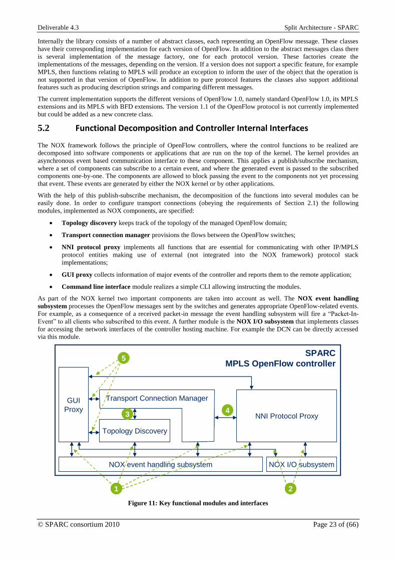
5 MPLS OpenFlow Controller Architecture
One key prototyping target was to develop an OpenFlow controller demonstrating the use cases described in Section 2.
Instead of developing a novel controller we decided to make use of an already existing controller framework. In July
2010, when the prototyping activity was started, the NOX [3] was the only available open source OpenFlow controller
framework. Since then, several controller frameworks were published as open source, e.g., Beacon [4], Maestro [5] and
Trema [6]. Obviously the different solutions have different software architectures. Therefore the migration to those
controllers would cause more-or-less rewriting most of the developed components and they do not provide such features
that would necessitate the migration.
Adopting the NOX controller framework allowed us to put focus on designing and implementing the control features
required by the different used cases. This chapter presents the developed controller architecture by discussing the major
functional entities together with the interface between these entities. Nevertheless, updates to the NOX framework were
inevitable, so we briefly discuss NOX and the added updates too.
5.1 NOX Controller Framework and Associated Tools
The NOX is an open-source OpenFlow controller framework. Its main purpose is to give a simple platform for
prototyping network control software. It provides a simple kernel module that handles the OpenFlow protocol sessions
and implements a component management framework. The latter solves the dynamic loading and running of user
developed components. The NOX is shipped with several already available components: most of them are just tutorial
ones showing how to develop components to NOX.
Due to its simplicity this kernel does not provide failure tolerant operation or enhanced multi-threading capabilities. Its
simplicity, however, make the extension or update of the kernel simple: resulting in rapid upgrade of the OpenFlow
protocol and fast introduction of new features to the system. This made the NOX a good controller framework for
SPARC.
5.1.1 Extensions to the NOX Framework
The baseline NOX controller kernel we used supported the standard OpenFlow 1.0. To support the extended OpenFlow
1.0 version, which also implements for instance MPLS and BFD configuration, the NOX kernel has been upgraded.
This upgrade affected the protocol message construction mechanisms, the protocol state machines and last but not least
some internal APIs (for instance some identifiers were upgrade from 16 bits to 32 bits). This led to a NOX version that
is able to configure the data plane switches used during the demonstration via OpenFlow; however, it is not able to
manage any standard OpenFlow 1.0 switches.
5.1.2 LibOFP Message Construction Library
Just for the sake of completeness we briefly discuss the LibOFP message construction library here as well though it was
originally presented in D4.1. This library creates a version-independent and easy to use abstraction of the OpenFlow
protocol. The library enables faster development as the protocol messages creation and parsing is handled by the library,
including the specifics of the different protocol versions and the specifics of the message packing. The library is used in
the extensions to the NOX controller.
A user of the library creates messages from a “message factory”, which returns an implementation of an abstract class;
and which implementation that is returned depends on which protocol version the developer selected when creating the
message factory. This enables an application using LibOFP to support several different version of the OpenFlow
protocol while still having the same messaging code. Using the library a controller could support switches with different
protocol versions simply changing the factory used, which can be done depending on the version of the connected
switch.
Figure 10: A common abstract model for all implementation is given.
Deliverable 4.3 Split Architecture - SPARC
© SPARC consortium 2010 Page 23 of (66)
Internally the library consists of a number of abstract classes, each representing an OpenFlow message. These classes
have their corresponding implementation for each version of OpenFlow. In addition to the abstract messages class there
is several implementation of the message factory, one for each protocol version. These factories create the
implementations of the messages, depending on the version. If a version does not support a specific feature, for example
MPLS, then functions relating to MPLS will produce an exception to inform the user of the object that the operation is
not supported in that version of OpenFlow. In addition to pure protocol features the classes also support additional
features such as producing description strings and comparing different messages.
The current implementation supports the different versions of OpenFlow 1.0, namely standard OpenFlow 1.0, its MPLS
extensions and its MPLS with BFD extensions. The version 1.1 of the OpenFlow protocol is not currently implemented
but could be added as a new concrete class.
5.2 Functional Decomposition and Controller Internal Interfaces
The NOX framework follows the principle of OpenFlow controllers, where the control functions to be realized are
decomposed into software components or applications that are run on the top of the kernel. The kernel provides an
asynchronous event based communication interface to these component. This applies a publish/subscribe mechanism,
where a set of components can subscribe to a certain event, and where the generated event is passed to the subscribed
components one-by-one. The components are allowed to block passing the event to the components not yet processing
that event. These events are generated by either the NOX kernel or by other applications.
With the help of this publish-subscribe mechanism, the decomposition of the functions into several modules can be
easily done. In order to configure transport connections (obeying the requirements of Section 2.1) the following
modules, implemented as NOX components, are specified:
Topology discovery keeps track of the topology of the managed OpenFlow domain;
Transport connection manager provisions the flows between the OpenFlow switches;
NNI protocol proxy implements all functions that are essential for communicating with other IP/MPLS
protocol entities making use of external (not integrated into the NOX framework) protocol stack
implementations;
GUI proxy collects information of major events of the controller and reports them to the remote application;
Command line interface module realizes a simple CLI allowing instructing the modules.
As part of the NOX kernel two important components are taken into account as well. The NOX event handling
subsystem processes the OpenFlow messages sent by the switches and generates appropriate OpenFlow-related events.
For example, as a consequence of a received packet-in message the event handling subsystem will fire a “Packet-In-
Event” to all clients who subscribed to this event. A further module is the NOX I/O subsystem that implements classes
for accessing the network interfaces of the controller hosting machine. For example the DCN can be directly accessed
via this module.
SPARC
MPLS OpenFlow controller
Transport Connection Manager
NOX event handling subsystem
Topology Discovery
NNI Protocol Proxy
NOX I/O subsystem
GUI
Proxy
Transport Connection Manager
1 2
34
5SPARC
MPLS OpenFlow controller
Transport Connection Manager
NOX event handling subsystem
Topology Discovery
NNI Protocol Proxy
NOX I/O subsystem
GUI
Proxy
Transport Connection Manager
1 2
34
5
Figure 11: Key functional modules and interfaces

Deliverable 4.3 Split Architecture - SPARC
© SPARC consortium 2010 Page 24 of (66)
Between these modules a set of interfaces are defined. With these interfaces the relation between the modules can be
described. Five interfaces have been defined as shown on Figure 11:
1. The NOX event handling subsystem generates OpenFlow protocol related events, for example packet-in
message received, or a flow has expired. Through this interface the different components can subscribe to these
events as well as initiate flow configuration messages.
2. The NOX I/O subsystem provides an interface to establish connections to other software applications running
on the DCN. Such applications are the NNI Protocol Proxy and the graphical frontend of the prototype.
3. The Topology Discovery component reports topology changes, like the detection or a disconnection of a new
link. Important to note that the connection or failure of an OpenFlow switch is already detected by the
controller so events are generated through interface (1).
4. Through this interface the Transport Connection Manager (TCM) can be requested to provision MPLS LSPs
between two OpenFlow nodes. The TCM responds with the details of the configured MPLS LSP.
5. This interface between the GUI proxy and other components allows those components to pass events toward
the graphical frontend through the proxy module.
Beside the above five internal interfaces a further one to the CLI module is defined. Through this interface the different
modules can add their own commands to the CLI and register their listener functions that the CLI will invoke upon
receiving the appropriate registered command. This way the CLI passes commands with the list of attributes to the
module which registered the command.
5.3 Graphical User Interface Proxy Component
The Extensible Network Visualization and Control Framework (ENVI) [27] is a continuously evolving platform for
enabling networking visualization. The ENVI itself is the standalone GUI application while a NOX application, referred
to as LAVI [28], acts as GUI backend module. However, the ENVI/LAVI architecture was in early stage when the
prototyping activity started. Therefore, we decided to exploit our competence in developing GUIs and to develop a
novel GUI application as well as a dedicated NOX application. The resulted solution follows the architecture shown on
Figure 12 and comprises of the following elements:
The Graphical User Interface application visualizes the state of the OpenFlow domain formed by a set of
OpenFlow switches as well as of the controller itself. Unlike management systems, which have direct access to
the network elements, the GUI application is in connection with the controller over “northbound interface”.
Based on its internal state and events, the controller generates notifications and passes them to the GUI. The
GUI constructs a local representation of the OpenFlow domain and refreshes this local representation based on
the notifications.
The Controller implements a component called as GUI Proxy. This application monitors the internal events of
NOX: It subscribes to amongst others the “switch join” & “switch leave” and link status change events.
Besides, it introduces further events, which allows other components, like the transport controller to report the
configured flows. Upon receiving any of these events, the GUI Proxy translates them to notifications, which
are sent to the connected GUI application. In the case when the GUI application is not yet connected, the plug-
in stores the events in a queue, and when the GUI connects the GUI plug-in application sends notifications for
all previously received events to the GUI.

Deliverable 4.3 Split Architecture - SPARC
© SPARC consortium 2010 Page 25 of (66)
Graphical User Interface
ApplicationOpenFlow Controller
Application
OpenFlow Switch OpenFlow Switch OpenFlow Switch
(1)
(2)
GU
I AP
P
BA
CK
EN
D
Graphical User Interface
ApplicationOpenFlow Controller
Application
OpenFlow Switch OpenFlow Switch OpenFlow Switch
(1)
(2)
Graphical User Interface
ApplicationOpenFlow Controller
Application
OpenFlow Switch OpenFlow Switch OpenFlow Switch
(1)
(2)
GU
I AP
P
BA
CK
EN
D
Figure 12: Attaching Graphical User Interface to NOX controller
The interfaces between the different modules are also as shown on Figure 12. In the followings, we will focus on the
interface between the controller and the GUI application (indicated with (2)). This interface allows full separation of the
GUI and the controller and it expects only IP connectivity between the two entities. As transport layer protocol it uses
TCP and uses JavaScript Object Notation (JSON) [33] to serialise data structures encoding the notifications. With the
help of these notification messages a simple protocol has been defined comprising of the following steps:
During session establishment the GUI application connects to the controller over TCP by sending a HELLO
message. This message carries the name of the GUI application encoded in a string. The controller also sends a
HELLO message that encodes the name of the controller.
Immediately after the session establishment both, the GUI application and the proxy enter to the up state. In
this state the proxy sends notification to the GUI.
The following notification types have been defined so far:
A node has connected to the controller. This description comprises of the datapath identifier, the user friendly
name, the node type, and the list of port descriptors. These latter descriptors carry the major port attributes
(identifiers, name, speed and status). The node type field encodes the role of the node to be connected (e.g.,
end user facing edge node). This event is also used to report non-OpenFlow switches. For example the
IP/MPLS routers connected to the OpenFlow domain are reported using this notification. In this latter case,
some attributes are not fully set.
A node has disconnected from the controller. Here, the node identifier is encoded in the notification.
Detection of a new link between two nodes. Each link has been characterised by its endpoint, i.e., a port where
the link is terminated. The combination of the node identifier and the node local port one specifies an endpoint.
Detection of a link disconnection/failure between two nodes. Same attributes as in previous notification,
applies.
An MPLS flow has been configured. The flows are described as a set of hops, where the hops are mapped to
the physical links. This means that the hops are also described with the endpoints of the underlying link.
Beside the hop set, the name of the tunnel is also given.
A pair of MPLS flows has been configured, for implementing 1:1 path protection. The two paths have been
specified via two hop sets.
The GUI application visualises the above received notifications as shown on Figure 13. It is able do show the node
types considered during the use cases: regular OpenFlow nodes, OpenFlow Access Nodes, IP/MPLS routers, Servers,
End users and BRAS nodes. All these nodes are reported using the same “node connected” messages. Besides, the
physical links between the nodes are depicted. Last but not least, the flows configured by the controller are also shown.
Note, that the GUI is able to show any kind of flow implemented connectivity: point-to-point, point-to-multipoint,
multipoint-to-point. Note, that the internal architecture of the GUI application is not detailed here as it is not relevant in
the point of view of the controller architecture.
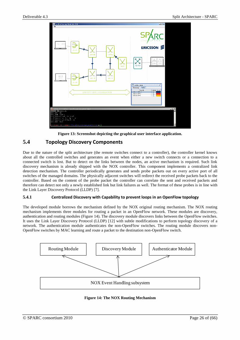
Deliverable 4.3 Split Architecture - SPARC
© SPARC consortium 2010 Page 26 of (66)
Figure 13: Screenshot depicting the graphical user interface application.
5.4 Topology Discovery Components
Due to the nature of the split architecture (the remote switches connect to a controller), the controller kernel knows
about all the controlled switches and generates an event when either a new switch connects or a connection to a
connected switch is lost. But to detect on the links between the nodes, an active mechanism is required. Such link
discovery mechanism is already shipped with the NOX controller. This component implements a centralized link
detection mechanism. The controller periodically generates and sends probe packets out on every active port of all
switches of the managed domains. The physically adjacent switches will redirect the received probe packets back to the
controller. Based on the content of the probe packet the controller can correlate the sent and received packets and
therefore can detect not only a newly established link but link failures as well. The format of these probes is in line with
the Link Layer Discovery Protocol (LLDP) [7].
5.4.1 Centralized Discovery with Capability to prevent loops in an OpenFlow topology
The developed module borrows the mechanism defined by the NOX original routing mechanism. The NOX routing
mechanism implements three modules for routing a packet in an OpenFlow network. These modules are discovery,
authentication and routing modules (Figure 14). The discovery module discovers links between the OpenFlow switches.
It uses the Link Layer Discovery Protocol (LLDP) [12] with subtle modifications to perform topology discovery of a
network. The authentication module authenticates the non-OpenFlow switches. The routing module discovers non-
OpenFlow switches by MAC learning and route a packet to the destination non-OpenFlow switch.
NNOX Event Handling subsystem
N N NRouting Module Discovery Module Authenticator Module
Figure 14: The NOX Routing Mechanism
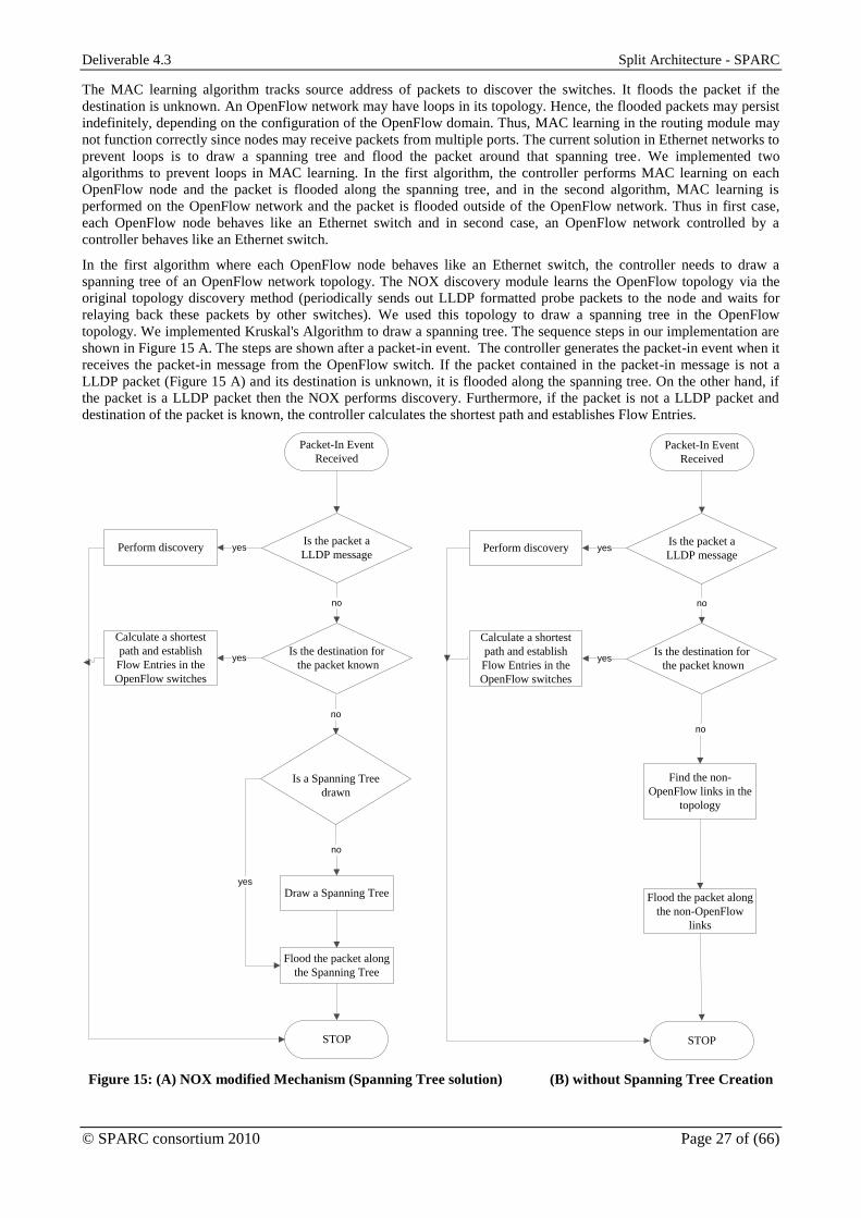
Deliverable 4.3 Split Architecture - SPARC
© SPARC consortium 2010 Page 27 of (66)
The MAC learning algorithm tracks source address of packets to discover the switches. It floods the packet if the
destination is unknown. An OpenFlow network may have loops in its topology. Hence, the flooded packets may persist
indefinitely, depending on the configuration of the OpenFlow domain. Thus, MAC learning in the routing module may
not function correctly since nodes may receive packets from multiple ports. The current solution in Ethernet networks to
prevent loops is to draw a spanning tree and flood the packet around that spanning tree. We implemented two
algorithms to prevent loops in MAC learning. In the first algorithm, the controller performs MAC learning on each
OpenFlow node and the packet is flooded along the spanning tree, and in the second algorithm, MAC learning is
performed on the OpenFlow network and the packet is flooded outside of the OpenFlow network. Thus in first case,
each OpenFlow node behaves like an Ethernet switch and in second case, an OpenFlow network controlled by a
controller behaves like an Ethernet switch.
In the first algorithm where each OpenFlow node behaves like an Ethernet switch, the controller needs to draw a
spanning tree of an OpenFlow network topology. The NOX discovery module learns the OpenFlow topology via the
original topology discovery method (periodically sends out LLDP formatted probe packets to the node and waits for
relaying back these packets by other switches). We used this topology to draw a spanning tree in the OpenFlow
topology. We implemented Kruskal's Algorithm to draw a spanning tree. The sequence steps in our implementation are
shown in Figure 15 A. The steps are shown after a packet-in event. The controller generates the packet-in event when it
receives the packet-in message from the OpenFlow switch. If the packet contained in the packet-in message is not a
LLDP packet (Figure 15 A) and its destination is unknown, it is flooded along the spanning tree. On the other hand, if
the packet is a LLDP packet then the NOX performs discovery. Furthermore, if the packet is not a LLDP packet and
destination of the packet is known, the controller calculates the shortest path and establishes Flow Entries.
Packet-In Event
Received
Is the packet a
LLDP messagePerform discovery
Is the destination for
the packet known
Calculate a shortest
path and establish
Flow Entries in the
OpenFlow switches
Is a Spanning Tree
drawn
Draw a Spanning Tree
Flood the packet along
the Spanning Tree
yes
no
yes
no
no
yes
STOP
Packet-In Event
Received
Is the packet a
LLDP messagePerform discovery
Is the destination for
the packet known
Calculate a shortest
path and establish
Flow Entries in the
OpenFlow switches
Flood the packet along
the non-OpenFlow
links
yes
no
yes
no
STOP
Find the non-
OpenFlow links in the
topology
Figure 15: (A) NOX modified Mechanism (Spanning Tree solution) (B) without Spanning Tree Creation

Deliverable 4.3 Split Architecture - SPARC
© SPARC consortium 2010 Page 28 of (66)
In the second algorithm where an OpenFlow network behaves like an Ethernet switch, the controller needs to know the
non-OpenFlow links to flood the packet outside of the OpenFlow network. The non-OpenFlow links are the links in the
topology connected to the non-OpenFlow switches. In our implementation of this algorithm, reception or non-reception
of a LLDP packet declares a link as an OpenFlow or a non-OpenFlow link. In the production network, there could be
two situations (1) a non-OpenFlow switch does not transmit any LLDP packet (may be because it does not run its own
LLDP protocol) (2) a non-OpenFlow switch transmits a LLDP packet to the OpenFlow network (may be because it runs
its own LLDP protocol). We consider both the situations while declaring a link as a non-OpenFlow link. The controller
in our implementation registers the MAC addresses of all the Ethernet interfaces of the OpenFlow switches when it
receives the feature-reply message in the initial phase of connection. The controller declares a link as a non-OpenFlow
link in one of the following situations (1) if it has not received any LLDP packet from the link (2) it has received the
LLDP packet but the MAC address of the LLDP packet is not the registered MAC address of any of the Ethernet
interface of the OpenFlow switches. The sequence of steps that are followed in this implementation is shown in Figure
15 B. Like first algorithm, all the actions are taken upon packet-in event. The packet is first checked whether it is a
LLDP packet or whether destination is known for the non-LLDP packet. Now if the destination is not known then the
controller finds the non-OpenFlow links in the topology and floods the packet along the non-OpenFlow links (Figure 15
B).
The OpenFlow switch can send a first few bytes of the packet or all the bytes of the packet to the controller in the
packet-in message. It depends on configuration of the switch. In the second implemented algorithm, we transmitted all
the bytes of the packet to the controller because the packet in packet-in message is flooded to the destination non-
OpenFlow switch in this implementation.
5.4.2 Centralized Discovery with Distributed Continuity Check
The developed enhanced component borrows the centralized discovery mechanism as well as the link state change
events defined by the NOX original discovery module. It makes possible upgrading to the enhanced discovery
component without rewriting any other components. The developed component maintains a collection of all discovered
adjacencies and keeps track of those adjacencies. The following attributes are assigned as well: the time of the last
probe packet that monitors this link and the state of the adjacency which can be either up or down. Upon receiving a
previously emitted probe packet, the controller performs the following steps:
1. it checks if the adjacency indicated by the probe packet were previously detected;
2. when a not-yet-stored adjacency is identified, it adds its description to the collection;
3. if the adjacency is already known by the controller or just created, it just updates its state to up as well as the
last probe packet time is set to the epoch of receiving the probe packet; and
4. it generates a link state up event.
On the other hand, it periodically checks which of the stored adjacencies are expired, i.e., the difference between the
current system time and the last probe packet reception time exceeds a threshold. Then, the states of such adjacencies
are set to down and a link state down event per updated adjacencies is generated.
The above threshold is referred to as “detection time” and expresses the delay between the impairment and its detection.
To guarantee the detection time for any of the links and to avoid false detections caused by delays and accidental packet
losses, the interval between subsequent probe packets are set to detection time divided by 3.5 [8]. But to support the
prescribed probe-packet-delay for each link, the controller must generate the probe packets at the rate of
2__
1 Links
delaypacketprobe.
Besides discovering the topology, the centralized discovery mechanism is applicable to detect link or node failures
within a few seconds. But to monitor the health of links for recovery purposes more strict time requirements will be set.
For instance to reach 50 milliseconds recovery time, probe packets must be sent approximately a 10 millisecond interval
(100 packets per second) per link. In a transport network it is not unusual to have hundreds of links. Hence the
controller must be able to handle and react to millions of monitoring packets per second just to monitor the health of the
network. This is not just a burden on the controller; it also imposes an unacceptable load on the control network. But by
using other means to detect link failures the detection time can be set two or three orders of magnitude higher, which
alleviate scalability concerns. One possible solution is to implement the link health detection in a distributed fashion. To
do this, we apply the BFD based OAM toolset, which was originally developed to implement the MPLS LSP continuity
check. This module can be configured for link continuity check as well.
One side effect of adopting the probe packet based link discovery is that it will discover the two directions of a
bidirectional link independently. While only this mechanism for topology change detection only, the issue of correlating
two anti-parallel adjacencies and identify a bidirectional link can be delegated to client components. However, the BFD

Deliverable 4.3 Split Architecture - SPARC
© SPARC consortium 2010 Page 29 of (66)
based OAM tool operates only over bidirectional links. Thus, the discovery application must also correlate the detected
adjacencies; and the states associated to each adjacency are extended with a new one referred to as “bidirectional up”.
This state indicates that an anti-parallel adjacency is found and is in up state. When a pair of adjacencies enters to
“bidirectional up” state BFD OAM monitoring endpoints will be configured to check the health of that link.
The monitoring endpoints deployed at the switches notify the controller about different events, like link loss or link
reestablishment. The discovery component subscribes to these events as well, and if a link is detected to loss
connectivity the states associated to the adjacency is set to down.
5.5 Transport Connection Manager Component
5.5.1 Key Functional Elements
The Transport Connection Manager component (also called “Transport Controller”) plays a key role in managing the
OpenFlow controller network domain: It provisions MPLS LSP in the controller domain. It also keeps track of the
topology of the OpenFlow network domain and issues re-configuration of the provisioned MPLS LSPs as needed. Last
but not least, it also provides an interface to the other components over which the configuration of a new MPLS LSP
can be requested. The main elements and their relation are depicted below, in Figure 16.
Transport Connection Manager
Topology
database
1
2
4
5
3
MPLS LSP requesting I/F
GUI proxy reporting I/F
Topology discovery I/F
Flow Managers
Request handling
Me
rgin
g tre
e
Mu
ltica
st tre
e
Pro
tecte
d P
ath
OpenFlow domain
topology maintenance
NOX kernel (event handling + message sending)
Transport Connection Manager
Topology
database
1
2
4
5
3
MPLS LSP requesting I/F
GUI proxy reporting I/F
Topology discovery I/F
Flow Managers
Request handling
Me
rgin
g tre
e
Mu
ltica
st tre
e
Pro
tecte
d P
ath
OpenFlow domain
topology maintenance
NOX kernel (event handling + message sending)
Figure 16: Major building blocks and their relations of Transport Connection Manager
The core of the whole component is the topology database. This database stores all data of the OpenFlow switches and
the links between the switches forming the managed network domain. It represent the topology as a directed graph with
attributes associated to the edges, where the vertices are the OpenFlow switches and the edges indicate the adjacencies
that are in up state. The attributes assigned to the edges encode the capacity available over that adjacency. Further
traffic engineering related attributes can also be assigned, for instance load over that link or measured delay.
The database is maintained dynamically by the OpenFlow domain topology maintenance module (see interface 1 of
Figure 16). Switches are added to the database right after the OpenFlow protocol session establishment (i.e., when the
switch joins to the controller) and they are deleted once the OpenFlow connection is disconnected. The links between
the switches are discovered making use of either discovery component provided with the NOX or one of the enhanced
discovery components (see Figure 16).
The Transport Connection Manager supports the configuration of different types of MPLS flows:
The unidirectional multipoint-to-point MPLS merging trees are simple constructions to carry best effort traffic
to one destination switch from all other ones. The routes from different sources to the same destination shares
the data plane resources on their common segments.
Co-routed bidirectional point-to-point MPLS flows to carry distinguished traffic, e.g., prioritized LSPs. The
health of these tunnels can be monitored with BFD.

Deliverable 4.3 Split Architecture - SPARC
© SPARC consortium 2010 Page 30 of (66)
Protected bidirectional point-to-point MPLS connections implemented using link disjoint co-routed
bidirectional point-to-point MPLS flows applying a 1:1 path protection scheme [26]. Both flows are monitored
with BFD to detect any failures on the links.
Unidirectional point-to-multipoint MPLS flows, or multicast trees, presents the multicasting capabilities of an
OpenFlow switch and allows efficient transport of such traffic in the domain.
Configuration of MPLS LSPs or flows is done by dedicated modules called flow managers. All flow managers have
access to the topology database (interface 4 of Figure 16) and use their graph data structures in order to perform any
path calculations upon different triggers. Each flow manager must realize two functions:
It configures new MPLS flows upon requests (interface 3 of Figure 16) and stores the MPLS flow’s essential
attributes (source & destination node, list of traversing nodes, port and label information) in its local data base.
It optionally reconfigures the affected MPLS flow in the case of a link failure (interface 2 of Figure 16).
The requests for configuring new MPLS flows are generated by other controller components. The request handling
module receives these configuration request events and passes them to the appropriate flow manager based on the type
and the content of the trigger event. The transport controller expects the following trigger events:
a point-to-point tunnel between two datapath,
a protected bidirectional tunnel between two datapaths, and
a multicast tunnel from a certain root toward a set of leaves.
These triggers are mapped to the implemented flow managers as shown in Table 2. It shows that the regular
unidirectional point-to-point tunnels are eventually implemented making use of merging trees.
Table 2: Mapping configuration requests to flow managers
Configuration trigger event Assigned flow manager
Point-to-point tunnel MPtP merging tree manager
Protected bidirectional tunnel Protected tunnel manager
Multicast tunnel Multicast tree manager
The discovery component is responsible for monitoring the health of the links and for reporting any link errors to the
OpenFlow domain maintenance module. Upon link or node failure this latter module notifies all running flow managers
about the failure and requests them to initiate the necessary subsequent actions. These actions, what the flow managers
will execute, can be for instance the reconfiguration of affected/all tunnel or it can just ignore the request if it does not
apply.
In the following subsections the details of each implemented flow manager will be discussed.
5.5.2 MPtP Merging Tree Manager
The multipoint-to-point merging tree manager aims at implementing control functions of configuring best effort
unidirectional point-to-point tunnels and dynamically rerouting them upon physical link failures. As all tunnels
managed by this entity are best effort, no QoS requirements were set. Therefore, they are routed along their shortest
path. This allows us using shared forwarding, where the point-to-point paths share all their resources, even the
forwarding entries over the common segments. Grouping the point-to-point tunnels together and handling them as one
multipoint-to-point merging tree radically decreases the number of managed entities. By considering an OpenFlow
domain comprising of N datapaths, we must configure N2 tunnels to provide full connectivity between every node pairs.
Using merging trees the number of entities to be managed will be dropped from N2 to N, which efficiently enhances
scalability and decreases the controller response time.
It is important to indicate a drawback of this shared forwarding. Based only on the LSP label, which is actually shared,
one cannot distinguish the different connections. However, at the egress datapath the payload carried by the merging
tree is further processed, which alleviates the issue.
Upon a request this flow manager configures such a tree as a spanning tree of the topology. In other words, it configures
shortest paths from all other datapaths toward the destination one, even if just a single point-to-point tunnel from one
node is requested. To calculate such a merging tree the following algorithm is used:
1. A directed graph EVG , is constructed from the topology, where vertices V represent the datapaths of the
OpenFlow domain and each active physical link is depicted as a pair of unidirectional graph edges. Then some
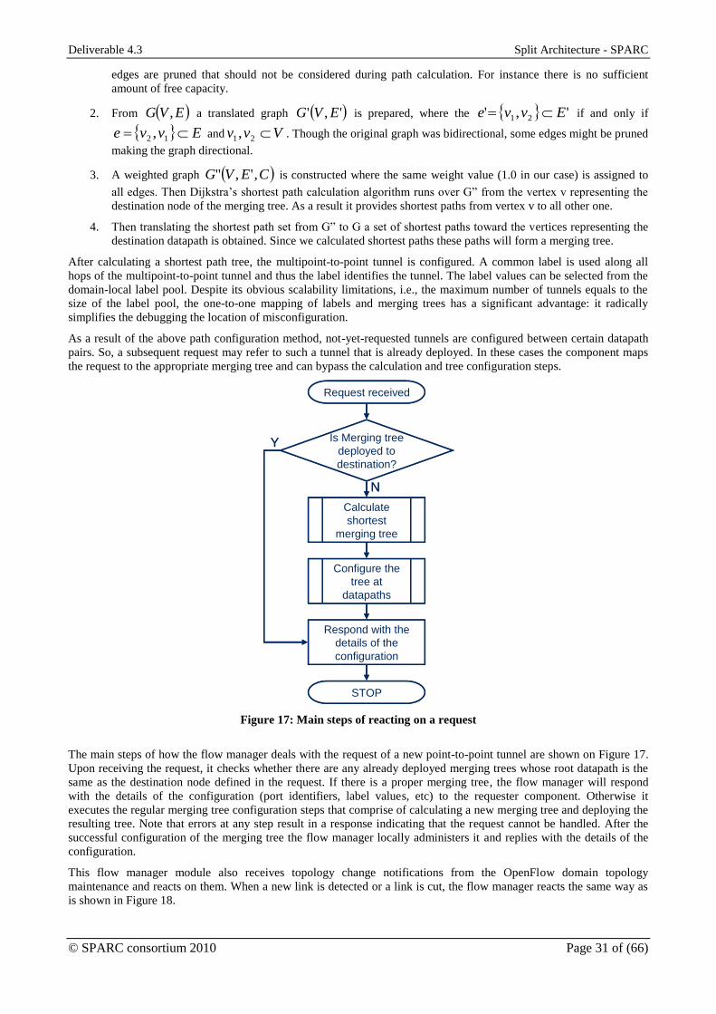
Deliverable 4.3 Split Architecture - SPARC
© SPARC consortium 2010 Page 31 of (66)
edges are pruned that should not be considered during path calculation. For instance there is no sufficient
amount of free capacity.
2. From EVG , a translated graph ',' EVG is prepared, where the ',' 21 Evve if and only if
Evve 12 , and Vvv 21, . Though the original graph was bidirectional, some edges might be pruned
making the graph directional.
3. A weighted graph CEVG ,'," is constructed where the same weight value (1.0 in our case) is assigned to
all edges. Then Dijkstra’s shortest path calculation algorithm runs over G” from the vertex v representing the
destination node of the merging tree. As a result it provides shortest paths from vertex v to all other one.
4. Then translating the shortest path set from G” to G a set of shortest paths toward the vertices representing the
destination datapath is obtained. Since we calculated shortest paths these paths will form a merging tree.
After calculating a shortest path tree, the multipoint-to-point tunnel is configured. A common label is used along all
hops of the multipoint-to-point tunnel and thus the label identifies the tunnel. The label values can be selected from the
domain-local label pool. Despite its obvious scalability limitations, i.e., the maximum number of tunnels equals to the
size of the label pool, the one-to-one mapping of labels and merging trees has a significant advantage: it radically
simplifies the debugging the location of misconfiguration.
As a result of the above path configuration method, not-yet-requested tunnels are configured between certain datapath
pairs. So, a subsequent request may refer to such a tunnel that is already deployed. In these cases the component maps
the request to the appropriate merging tree and can bypass the calculation and tree configuration steps.
Request received
Respond with the
details of the
configuration
Is Merging tree
deployed to
destination?
Calculate
shortest
merging tree
Configure the
tree at
datapaths
N
Y
STOP
Request received
Respond with the
details of the
configuration
Is Merging tree
deployed to
destination?
Calculate
shortest
merging tree
Configure the
tree at
datapaths
N
Y
STOP
Figure 17: Main steps of reacting on a request
The main steps of how the flow manager deals with the request of a new point-to-point tunnel are shown on Figure 17.
Upon receiving the request, it checks whether there are any already deployed merging trees whose root datapath is the
same as the destination node defined in the request. If there is a proper merging tree, the flow manager will respond
with the details of the configuration (port identifiers, label values, etc) to the requester component. Otherwise it
executes the regular merging tree configuration steps that comprise of calculating a new merging tree and deploying the
resulting tree. Note that errors at any step result in a response indicating that the request cannot be handled. After the
successful configuration of the merging tree the flow manager locally administers it and replies with the details of the
configuration.
This flow manager module also receives topology change notifications from the OpenFlow domain topology
maintenance and reacts on them. When a new link is detected or a link is cut, the flow manager reacts the same way as
is shown in Figure 18.

Deliverable 4.3 Split Architecture - SPARC
© SPARC consortium 2010 Page 32 of (66)
Link state notification
Are there not
updated Merging
trees?
Calculate
shortest
merging tree
Configure the
tree at
datapaths
Y
N
STOP
Link state notification
Are there not
updated Merging
trees?
Calculate
shortest
merging tree
Configure the
tree at
datapaths
Y
N
STOP
Figure 18: Flow manager procedures upon receiving a link state update (up/down) notification
The flow manager will iterate over all already deployed merging trees and reconfigures them as follows. It re-calculates
a shortest merging tree using the changed topology and re-configures the merging tree regardless of it being affected by
the topology change or not. At first sight, this solution seems to be destructive and not scalable: one might think that it
will cut such flows during reconfiguring the whole tree that are not cut by the topology change. However, OpenFlow
allows us the rewrite a flow configuration entry without disrupting the traffic forwarding according to that flow entry.
Exploiting this behaviour, the above reconfiguration of the tree will cause the temporal cut of only those flows that are
really rerouted.
This procedure of MPtP flow manager implements controller driven restoration. The supported failover times are in the
order of magnitudes of seconds.
5.5.3 Protected Tunnel Manager
Our measurements reported (see Deliverable 5.2) that controller based restoration in case of split architecture does not
allow reaching 50 milliseconds restoration times. To guarantee such stringent restoration the OpenFlow switch model
was extended with the support of protection mechanisms [30]. The protected tunnel manager is developed in order to
execute the configuration required to deploy bidirectional protected tunnels. With the help of OpenFlow protocol and
monitoring extensions discussed in D4.2, 1-to-1 path protection is configured, where the protected (or working) path
carries the traffic during normal operation and the endpoints switch to the protecting (or backup) path when protected
path is down. In order to check the state of both, the protected and the protecting paths BFD based OAM continuity
check is used (see D4.2 for further details).

Deliverable 4.3 Split Architecture - SPARC
© SPARC consortium 2010 Page 33 of (66)
Request received
Respond with the
details of the
configuration
Provision
protected path
Provision
protecting path
STOP
Respond with error
Successful
?
N YSuccessful
?
Y
N
Provision protected path
STOP
Provision protecting path
Temporary disable
link used by
protected path
Calculate
shortest path
Configure the
path with MEPs
Request received
Respond with the
details of the
configuration
Provision
protected path
Provision
protecting path
STOP
Respond with error
Successful
?
N YSuccessful
?
Y
N
Request received
Respond with the
details of the
configuration
Provision
protected path
Provision
protecting path
STOP
Respond with error
Successful
?
N YSuccessful
?
Y
N
Provision protected path
STOP
Provision protecting path
Temporary disable
link used by
protected path
Calculate
shortest path
Configure the
path with MEPs
Provision protected path
STOP
Provision protecting path
Temporary disable
link used by
protected path
Calculate
shortest path
Configure the
path with MEPs
Figure 19: Steps for configuring 1-to-1 protected path pair.
Upon receiving a request, this flow manager configures the pair link-disjoint paths one-by-one: first the protected path
and then the protecting one. The details for configuring the protected path are:
1. A directed graph EVG , is constructed from the topology, where vertices V represent the datapaths of the
OpenFlow domain and each active physical link is represented as a pair of unidirectional graph edges.
2. Shortest path from the first endpoint of the request to the second one is calculated using Dijkstra’s algorithm.
3. Along the determined path the bidirectional LSP is configured. In the point of view of label handling similar
consideration were done. This means that the same label value is used at all hops and in both directions. Since
the incoming port is also part of the forwarding entries configured, the two directions are still distinguishable
even if the same label value is used.
4. Monitoring endpoints are configured at both endpoint of the protected path.
Each monitoring endpoints (MEP) to be configured at the LSP endpoint comprises of a source and a sink MEP. The
source MEP is responsible for generating and formatting BFD monitoring frames. Then the endpoint is configured to
inject the generated BFD frames into the monitored LSP. At the peer edge the sink MEP is configured per tunnel to
extract monitoring packets from the tunnel, process them and keep track of its state.
The details of configuring the protecting path are:
1. A directed graph EVG , is constructed from the topology, where vertices V represent the datapaths of the
OpenFlow domain and each active physical links are represented as a pair of unidirectional graph edges. Then
the edges used by the protected path are excluded of the set E.
2. Continue with steps 2, 3, and 4 of above.
As a last step the flow manager binds the MEPs belonging to the protected and the protecting path. This binding is
required by the implemented protection extension (Section 3.5 of D4.2): it initiates the failover to the backup path if the
state of the MEP belonging to the protected path is down, while MEP of the protecting one is up. Note that, this
algorithm does not always find the existing solution. However, substituting it with more general algorithms, like
Suurballe-Tarjan algorithm [34]; would not influence the prototype behaviour. Introduction of such algorithms may be
done later.
Similarly to the MPtP flow manager; this manager also gets notifications from the OpenFlow domain topology
maintenance module. As the managed tunnels are protected by the switches the flow manager discards the topology
change events.
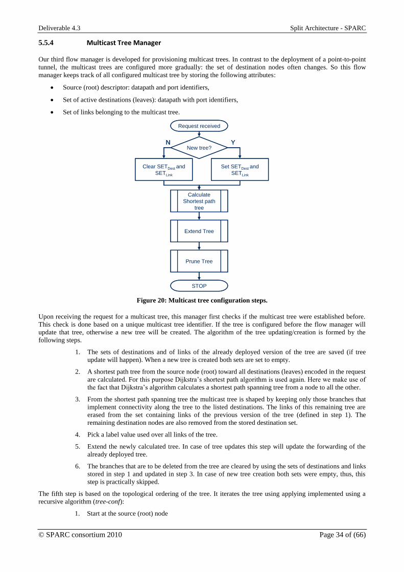
Deliverable 4.3 Split Architecture - SPARC
© SPARC consortium 2010 Page 34 of (66)
5.5.4 Multicast Tree Manager
Our third flow manager is developed for provisioning multicast trees. In contrast to the deployment of a point-to-point
tunnel, the multicast trees are configured more gradually: the set of destination nodes often changes. So this flow
manager keeps track of all configured multicast tree by storing the following attributes:
Source (root) descriptor: datapath and port identifiers,
Set of active destinations (leaves): datapath with port identifiers,
Set of links belonging to the multicast tree.
Request received
Clear SETDest and
SETLink
New tree?
Set SETDest and
SETLink
Calculate
Shortest path
tree
Extend Tree
Prune Tree
STOP
N Y
Request received
Clear SETDest and
SETLink
New tree?
Set SETDest and
SETLink
Calculate
Shortest path
tree
Extend Tree
Prune Tree
STOP
N Y
Figure 20: Multicast tree configuration steps.
Upon receiving the request for a multicast tree, this manager first checks if the multicast tree were established before.
This check is done based on a unique multicast tree identifier. If the tree is configured before the flow manager will
update that tree, otherwise a new tree will be created. The algorithm of the tree updating/creation is formed by the
following steps.
1. The sets of destinations and of links of the already deployed version of the tree are saved (if tree
update will happen). When a new tree is created both sets are set to empty.
2. A shortest path tree from the source node (root) toward all destinations (leaves) encoded in the request
are calculated. For this purpose Dijkstra’s shortest path algorithm is used again. Here we make use of
the fact that Dijkstra’s algorithm calculates a shortest path spanning tree from a node to all the other.
3. From the shortest path spanning tree the multicast tree is shaped by keeping only those branches that
implement connectivity along the tree to the listed destinations. The links of this remaining tree are
erased from the set containing links of the previous version of the tree (defined in step 1). The
remaining destination nodes are also removed from the stored destination set.
4. Pick a label value used over all links of the tree.
5. Extend the newly calculated tree. In case of tree updates this step will update the forwarding of the
already deployed tree.
6. The branches that are to be deleted from the tree are cleared by using the sets of destinations and links
stored in step 1 and updated in step 3. In case of new tree creation both sets were empty, thus, this
step is practically skipped.
The fifth step is based on the topological ordering of the tree. It iterates the tree using applying implemented using a
recursive algorithm (tree-conf):
1. Start at the source (root) node
Deliverable 4.3 Split Architecture - SPARC
© SPARC consortium 2010 Page 35 of (66)
2. If the node is not a leaf then invoke tree-conf algorithm on all child nodes. It also collects the outgoing
port toward the child nodes, and the labels to be used to reach those child nodes.
3. Configure the datapath represented by the current node. First a label value to be used to receive a
packet along the tree is selected. Then it formulates a multicast instruction construct (action set with
multiple outgoing ports in OpenFlow 1.0 or utilizing a group table entry in OpenFlow 1.1) and defines
a flow entry saying that any packet entering on the upstream port with the just selected label will be
treated according to the multicast instruction construct.
4. Returns with the label expected from the upstream node.
Since we configure a tree, which does not contain loops, the above algorithm will be done within finite steps.
Like the other flow managers, the Multicast tree manager gets notifications from the OpenFlow domain topology
maintenance module. However, this manager ignores those notifications. Developing resilient multicast trees were not
considered during our prototyping efforts.
5.6 NNI Protocol Proxy
The main goal of the NNI Protocol Proxy module is to implement all functions that are essential for provisioning such
transport connections that span over multiple control domains. Good examples are when an end-to-end MPLS tunnel
starts at a datapath in an OpenFlow controlled domain and terminated at an IP/MPLS router; or when datapaths
controlled by different OpenFlow controllers are interconnected with MPLS tunnels. To reach this goal the following
functionalities must be implemented by a controller:
Discovering adjacent control entities, establish and maintain a control session;
Exchanging information (e.g., identifiers, data structures, traffic engineering attributes) necessary to configure
the end-to-end tunnels;
Exchanging configuration information (i.e., signalling) with adjacent control entities;
Determine local endpoints (tunnel endpoints or border nodes) and ensure connectivity between these
endpoints;
Implement procedures to send and receive control messages toward/from adjacent control entities.
Initiate configuration of the controller datapath nodes according to the control communications.
The NNI Protocol Proxy reaches this goal via applying split architecture again. It exports all inter-control-plane
protocol procedures into a protocol stack module. This module is implemented as external software components loosely
integrated into the controller. This split allows outstanding flexibility: update of protocol implementations as well as
introduction of new protocols becomes much easier. Furthermore, externalizing the protocol implementations allows
using existing protocol stacks, like Quagga [22], Dragon [23] or G2MPLS [24]. However, these stacks originally were
developed to configure a single network element, not a set of datapaths. Therefore, a translator function is implemented
with the aim of supporting appropriate mapping between the controller’s local network representation and the one
provided toward the external protocol stack. To sum up, the protocol proxy module comprises of three major functional
modules:
The stack server module provides interfaces for the different protocol stacks, hiding the stack-specific
functions. The other modules see the stacks only through this interface. The stack-specific functions are
implemented as plug-ins.
The configuration translator module, as its name implies, implements all functions needed for the mapping. It
notifies the stack implementations on any updates affecting the stacks. It also gets the connection configuration
instructions sent by any of the signalling protocols and instructs other modules and NOX components on the
configuration updates.
Physical to logical port mapper maintains the mapping between the network domain border interfaces and their
logical representation. It also implements the relaying of Protocol Data Units (PDUs) such as OSPF and LDP
protocol messages. With the help of this module the protocol implementation can emit or receive PDUs. While
a protocol implementation sees only the logical interface, this module solves the seamless insertion or
demultiplexing of the PDUs.
The end-to-end tunnel manager keeps track of the transport connections spanning multiple domains. These
tunnels can be requested by other NOX modules. Upon receiving such a request, the module initiates message
exchanges and the configuration of the managed datapath nodes.

Deliverable 4.3 Split Architecture - SPARC
© SPARC consortium 2010 Page 36 of (66)
5.6.1 Integrating Quagga Stack
The Quagga [22] protocol stack is an open source router software suite, under GNU General Public License. It provides
roughly RIP, IS-IS, OSPF & BGP protocols. The standard stack does not support MPLS control plane either. However,
as part of a project, which implements MPLS forwarding under Linux, an LDP protocol daemon has been developed
making use of Quagga. This solution provides signalling support of establishing best effort MPLS tunnels and it also
provides TE capabilities for OSPF. Matching against the requirements set by our use case the Quagga protocol stack
with MPLS-LDP extensions serves as an adequate protocol stack implementation.
The Quagga, like its parent stack the Zebra, splits the implemented functions into two layers. The heart of the whole
stack is the zebra daemon. It is responsible for keeping track of the networking subsystem of the Linux kernel:
enumerates the interfaces, polls their status and configured attributes and the forwarding tables. It also configures the
kernel, e.g., downloads forwarding entries. For this purpose the zebra daemon uses the appropriate Linux APIs (see (1)
of Figure 21).
Towards the various protocols the Zebra daemon provides a unified interface. It shows a logical view of the router that
the different protocols can poll and configure. It also implements advanced functions, like route redistribution, where
one protocol daemon can be notified on the route updates done by any other protocol daemons. Over this unified
interface the Zebra protocol is used. Like OpenFlow the Zebra protocol can run on the top of TCP, making possible
physical separation of the different daemons. However, a limitation of this architecture is that the different protocol
daemons (OSPF and LDP in our example) use the Linux kernel directly to send/receive data packet.
Linux kernel
Zebra daemon
OSPF
daemon
LDP
daemon
…
Linux kernel API
(e.g. netlink and socket)
Abstract router API
Zebra protocol
1
23
Linux kernel
Zebra daemon
OSPF
daemon
LDP
daemon
…
Linux kernel API
(e.g. netlink and socket)
Abstract router API
Zebra protocol
1
23
Figure 21: Split architecture as it applied in Quagga
To integrate the Quagga stack into our controller both above interfaces, the Linux kernel API and the Zebra protocol
implement abstract router API were considered. As the Zebra protocol can use TCP as transport protocol and the Zebra
daemon implements the router abstraction function, we included a module implementing the required subset of the
Zebra daemon functionality. The resulting architecture is shown on Figure 22. Here two NOX modules take the
responsibilities of the Zebra daemon: the Quagga server and the Domain modeller modules.
The Quagga server implements the protocol interface toward the OSPF and LDP daemon with the requested functions.
The domain modeller implements the logical representation of the OpenFlow domain and translates between the
controllers’ internal and the simplified view reported toward the protocol daemons. Besides, the port mapper module
handles the packet sent to/received from the different protocol daemons.

Deliverable 4.3 Split Architecture - SPARC
© SPARC consortium 2010 Page 37 of (66)
Quagga server
OSPF
daemon
LDP
daemon
…Abstract router API
Zebra protocol
Port
mapper Domain Modeler
with vRIBNOX event interface
NOX Kernel
23
E2E
Tunnel
Manager
Quagga server
OSPF
daemon
LDP
daemon
…Abstract router API
Zebra protocol
Port
mapper Domain Modeler
with vRIBNOX event interface
NOX Kernel
23
E2E
Tunnel
Manager
Figure 22: Integrating Quagga stack into NOX via implementing NNI protocol proxy.
5.6.2 Domain Modeler & Configuration Translator
An issue with integrating IP/MPLS protocol stacks, like Quagga, is that they use a model where the network elements
are used as a black box and where a simple forwarding model is used. The Zebra daemon implements such
representation model in which it enumerates several interfaces while the forwarding rule set is described in a Route
Information Base (RIB). The various protocol daemons, like OSPF write their configuration entries into the RIB.
As the NOX controller communicates with the Zebra protocol daemons via the zebra protocol, it implements a minimal
but sufficient set of functions and data elements of the RIB. It comprises IPv4 routing entries. Each entry is indexed
with a prefix, which is an IPv4 network address with its associated network mask. Each entry stores set of instructions
(similar to OpenFlow actions) and these actions are as follows: send out on an interface and send to a next-hop node
(gateway).
Beside the RIB, the NOX controller also takes care of MPLS related configuration commands sent by the LDP
daemons. These elements, like in case of IPv4 routing elements, are populated into a table called Label Forwarding
Information Base (LFIB). The entries forming the LFIB are a pair of MPLS prefix and associated MPLS instructions.
The MPLS prefix is the MPLS label with its associated label space. For simplicity reasons platform-wide label space is
considered. This means that one label space is defined and all labels share that space. Two major MPLS instruction
types are defined for the LFIB:
Next Hop Label Forwarding Entry collects all information that is essential to forward an MPLS frame. It
comprises of the new Label value to be sued and the next-hop gateway IP address.
Null entry indicates that the MPLS tunnel is terminated, i.e., the outermost label is removed and the remaining
packet is about to reparse. If one MPLS label is in the stack the remaining packet will be treated as IPv4
packet.
Beside the RIB can also contain Next Hop Label Forwarding Entries. This configuration expresses that the IPv4 packet
matching to the FEC will be included into an MPLS tunnel.
Besides implementing the abstract model of the OpenFlow domain, the vRIB, this module acts as a translator between
the Quagga and the rest of the controller. The following table summarized the triggers received from different modules
and the associated reactions. Note that one trigger, the configure MPLS cross connection (between an ILM entry and an
MPLS NHLFE) is not yet implemented, since this event occurs if the OpenFlow domain is transit one between two
MPLS routers. The considered use case, however, does not expect such setups.

Deliverable 4.3 Split Architecture - SPARC
© SPARC consortium 2010 Page 38 of (66)
Table 3: List of triggers sent to Domain Modeler and the given responses.
Trigger description Origin of trigger Responses/reactions
Poll the list of NNI interfaces Quagga Reports all active NNI interfaces to the requesting
Quagga daemon
Datapath joins NOX If the datapath implements NNI interface, then (1)
configure the logical representation of the NNI
interface, (2) report this interface to the Quagga
stack
Datapath leaves NOX If the datapath implements NNI interface, then
report the removal of this interface to Quagga stack
Requesting router identifier
configuration
Quagga Response with router identifier configuration to
Quagga
IPv4 route description update Quagga (1) update the local vRIB, (2) redistribute the
message to the subscribing Quagga daemon
Incoming Label Mapping update Quagga (1) store the ILM descriptor in LFIB and (2) notify
the end-to-end tunnel tracking module
Next-Hop-Label-Forwarding-
Entry update
Quagga (1) store the NHFLE descriptor in LFIB and (2)
notify the end-to-end tunnel tracking module
IPv4 route to NHLFE mapping Quagga (1) associate IPv4 Route with an NHLFE descriptor
and (2) notify the end-to-end tunnel tracking module
Subscribe to route redistribution Quagga Subscribe the requesting Quagga daemon to any
route updates generated by an other daemon (its
identifier encoded in the message)
5.6.3 Port Mapper
The IP/MPLS control plane protocols are in-band. This means that the control plane messages transmitted together with
the regular data frames over the same medium. In the split architecture, however, the control plane protocols run
remotely, in a detached, out-of-band fashion. Therefore, the controller must provide mechanisms for
including/extracting the control messages into the appropriate data streams. The port mapper module implements this
function as follows. It provides logical interfaces to control plane protocols. Since in our case the Quagga protocols run
on the same machine as the controller, these logical interfaces are interfaces of the hosting machine. The port mapper
emulates an Ethernet link (more precisely Ethernet LAN) between the Quagga protocol daemons and the nodes
connected to the physical NNI port. For example, in the prototype the TAP tunnelling interface is used [31]. The
controller catches any packets sent through these logical interfaces and can process them.
The protocol mapper also runs an inventory of the so called NNI ports. These ports denotes such OpenFlow switch
ports that face with nodes that are not under the control of the controller and the IP/MPLS control protocols will be used
to negotiate with the peer node. Thus an NNI port is described with the pair of datapath and port identifiers. These NNI
ports are configured to relay control packets or the whole traffic to the controller.

Deliverable 4.3 Split Architecture - SPARC
© SPARC consortium 2010 Page 39 of (66)
OSPF
daemon
LDP
daemon
Port mapperNOX
event
interface
TUN/TAP
Interface
NOX Kernel
DataPath
DataPath
1
2
3
4 OSPF
daemon
LDP
daemon
Port mapperNOX
event
interface
TUN/TAP
Interface
NOX Kernel
DataPathDataPathDataPath
DataPathDataPathDataPath
1
2
3
4
OSPF
daemon
LDP
daemon
Port mapperNOX
event
interface
TUN/TAP
Interface
NOX Kernel
DataPath
DataPath
8
7
6
5 OSPF
daemon
LDP
daemon
Port mapperNOX
event
interface
TUN/TAP
Interface
NOX Kernel
DataPathDataPathDataPath
DataPathDataPathDataPath
8
7
6
5
`
Figure 23: Relaying the control packet through the port mapper
The port mapper defines a one-to-one mapping between the machine-local logical interfaces and the NNI ports. Figure
23 shows how a control packet is related through the port mapper following this association. The left hand side show
the “upstream direction”, where the packet relayed from the switch to the protocol daemon, while the right hand side
shows the opposite direction. Upon receiving a packet over an NNI port:
1. The switch sends this packet up to the controller using packet in message.
2. The Port Mapper module, subscribed to packet in events, checks if the packet is received on one of its stored
NNI ports.
3. It looks for logical interface associated to the NNI port and passes the packet through that port.
4. The protocol daemon connected to that virtual port receives the packet.
In the opposite direction the following steps performed:
5. The protocol daemon generates a control packet and sends it through the logical interface it is connected to.
6. The controller receives that packet over one of its managed logical interfaces, and it looks for the matching
NNI port instance.
7. If such instance found the packet is encapsulated into a packet out message and is passed to the datapath
elements hosting the NNI port.
8. The datapath receiving the packet out message sends the packet through the interface indicated in the packet
out message.
In our current prototype implementation the assignment between the logical and physical NNI ports are static in the
sense that they are bound together when the controller boots up – obtained from a configuration file – and cannot be
changed later. On the other hand the mapping is tracked, which means that the controller knows whether the datapath
hosting one/more NNI ports is whether up and connected to the controller.
5.6.4 End-to-end Path Manager
The NNI protocol controller modules, which have been discussed so far, are required to implement the communication
with adjacent control domains via IP/MPLS. However, they do not implement the tasks of (1) initiating the signalling of
transport connections spanning over multiple control domains (referred to as end-to-end connection) and (2) configure
the managed OpenFlow datapath nodes as a result of the signalling message exchanges. The End-to-end path manager
is designated to cope with these latter tasks.
For this purpose, the module keeps track of the descriptor of all end-to-end connections during their whole lifetime.
Each end-to-end connection instance is specified with its endpoints. Here we exploit that an end-to-end tunnel is
assumed to span between a locally controlled OpenFlow datapath node and a remote node, which is not under direct

Deliverable 4.3 Split Architecture - SPARC
© SPARC consortium 2010 Page 40 of (66)
control of our controller but is addressable via IP/MPLS signalling messages. This means that the local endpoint is the
concatenation of a datapath identifier (of the local node) and a reference number that allows making distinction between
end-to-end tunnels terminated at the same nodes. The remote endpoint is considered to be a numbered node, which
means that it has a unique IP address. This IP address is used to denote the remote endpoint. Beside these key
identifiers, the following attributes are also stored:
Identifier of the border datapath between the local domain and the adjacent one. Note that it also hosts the NNI
port as well.
Description of an intra-domain OpenFlow connection established between the local endpoint and the domain
border datapath nodes. This connection acts as virtual link and is managed by the Transport Controller module
(see Section 5.5).
Detailed configuration description at both the endpoint and the border datapath nodes. Based on these
attributes the end-to-end tunnel manager is able formulate appropriate flow configuration commands at both
nodes in order to implement the termination point at the local endpoint as well as to cross-connect the end-to-
end connection between the local and the adjacent control domains.
5.6.5 Dynamic Behavior: Booting Procedure
The following sections present the dynamic behaviour of the NNI protocol controller component. The following phases
have been prototyped:
Booting up the architecture and reporting NNI interfaces.
OSPF adjacency discovery and session establishment; IP database synchronization.
LDP adjacency discovery and session establishment.
End-to-end tunnel establishment via LDP signalling.
The OSPF and LDP daemons, after they have started, connect to the Quagga server module of the NNI protocol
controller via TCP. Both daemons request the NOX controller to report the node ID, which is actually a loopback IP
address at the controller. Beside, the LDP daemon subscribes to the route redistribution and requests the NOX controller
to relay update messages sent by other daemons (that is OSPF in our case) to it. At this point the control architecture has
been set and is ready to operate.
When a datapath connects to the controller, the NNI protocol controller looks for a NNI port towards the adjacent
control domain. If the datapath hosts such NNI port then the controller does the following:
1. Configures a logical interface at the controller and establishes a tunnel between the logical interface and the
NNI port in the port mapper module, and assigns an IP address to this interface;
2. Notifies the Quagga daemons about the creation of this logical interface and its detailed configuration.
After receiving a notification about the creation of a new interface the OSPF will start the neighbour discovery by
sending Hello messages over this newly created interface, if it is configured to do so. The OSPF configuration steps will
apply: the discovery of adjacent OSPF speakers, the selection of designated router and the synchronization of their
topology databases. After the successful synchronization the OSPF daemon calculates the shortest path and downloads
these routes as IPv4 route updates to the NOX controller, using the Zebra protocol.
Then the LDP daemon also discovers its adjacent protocol speaker node using HELLO messages and establishes an
LDP session that node.
5.6.6 Configuring End-to-End Tunnels
After setting up the OSPF and LDP sessions and after negotiating the OSPF routing databases, the system is ready for
configuring end-to-end tunnels. Then the LDP protocol speakers may send label binding messages to each other, these
messages specify the assignment of a Forwarding Equivalence Class (FEC) describing an IPv4 subnet, to a best effort
MPLS LSP. The LDP daemon may generate MPLS configuration related instructions (e.g., NHLFE entry creation) to
the NOX controller, which saves them into its virtual LFIB.

Deliverable 4.3 Split Architecture - SPARC
© SPARC consortium 2010 Page 41 of (66)
Requesting
Service
Component
End-to-end
tunnel manager
Domain model &
configuration
translator
Quagga
Plug-in
LDP
daemon
Local
Endpoint
switch
NNI
switch
1. E2E Tunnel request Create logical interface representing
the local endpoint
3. Register interface4.a. Interface ADD
4.b. Interface ADD
2. Poll upstream tun.
Generates Label Binding
for downstream direction
Check if upstream MPLS LSP already signaled
5.a. ILM update5.b. ILM update
6. Local endpoint
configured
Receives Label Binding
for upstream direction
7.a. NHLFE update7.b. NHLFE update
7.C. NHLFE KEY resp.
8.a. FEC-to-NHLFE8.b. FEC-to-NHLFE9. Remote endpoint
configured
Transport
CTRL
10. Request intra-openflow tunnel toward border datapath
11. Intra-openflow tunnel description
12. Datapath configuration
13. Datapath configuration
14. E2E Tunnel response
Figure 24: Interaction between modules in order to configure an end-to-end tunnel.
The end-to-end tunnels are configured upon request posted by other controller applications. In the prototype these are
typically service layer components that require a connection to a non-controller remote endpoint. The initiated
procedure is depicted on Figure 24 and comprises of the following steps:
1. The requesting application initiates the whole end-to-end tunnel configuration by posting a request to the
tunnel manager. This request specifies the datapath identifier of the local endpoint and the IP address of the
remote one. Then the tunnel manager creates a descriptor according to the request.
2. The tunnel manager checks if the upstream direction is already signalled, i.e., a next hop LDP speaker already
reported an LSP toward the IP address denoting the remote endpoint. If so it updates the tunnel descriptor
accordingly.
3. The tunnel manager creates a logical interface representing the local endpoint and registers this interface in the
domain model. The IP address assigned to this interface serves as an identifier for the endpoint during LDP
signalling.
4. Upon registering the local endpoint representing logical interface, an Interface ADD event detailing the logical
interface configuration is reported to the LDP daemon. The Quagga plug-in generates the required zebra
messages in step 4.b. Then the LDP daemon generates a Label Binding LDP message to the next-hop node in
which the FEC specifies the IP address of the logical interface.
5. Then the LDP daemon instructs the NOX controller about creating a new ILM entry. The Quagga server
processes the zebra message and relays this request to the domain modeller.
6. The domain modeller declares that the end-to-end LSP in downstream direction has been signalled and sends
this declaration to the end-to-end tunnel manager.
7. The configuration of the end-to-end LSP starts by receiving a Label Binding LDP message from the adjacent
protocol speaker. As a result of this message the LDP daemon instructs the controller about creating a new
NHLFE entry. The Quagga server processes the zebra message and relays this request to the domain modeller.
Besides, the NOX controller defines a unique key for the NHLFE entry, and responses with this key to the
LDP daemon.
8. The LDP daemon also sends a so called FEC-to-NHLFE instruction describing the mapping between the IP
address of the remote endpoint and the NHLFE key of the LSP to be used to reach that node.

Deliverable 4.3 Split Architecture - SPARC
© SPARC consortium 2010 Page 42 of (66)
9. The two previous steps together indicate that the upstream part of the end-to-end connection has been
signalled. About this fact the domain modeller notifies the end-to-end tunnel manager.
10. If both upstream and downstream direction LSP have been signalled the end-to-end tunnel manager, it has all
information to start configuring the OpenFlow domain. First it determines the domain border node toward the
next-hop control domain; and requests the configuration of tunnels from the local endpoint to the border node
and back. It passes the request to the Transport Controller.
11. The Transport Controller responds with the details of the transport tunnel including the virtual port parts
denoting the tunnel endpoints at the locale and endpoint and the border datapath, respectively.
12. The end-to-end tunnel manager configures the local endpoint via OpenFlow.
13. The end-to-end tunnel manager configures the border node via OpenFlow.
14. When all configurations have been done it notifies the client on the configuration of the end-to-end tunnel and
it provides details of the configuration, i.e., the virtual ports representing the tunnel at the local endpoints.
5.7 G2MPLS RSVP-TE Plug-in Component
G2
MP
LS
Qu
ag
ga
NOX OpenFlow Controller
NOX Kernel
Transport
Controller
Topology DB
OSPFD
LDPDzebra
protocol
Virtual interface poolCP PDU
RSVPCORBA
NNI
Controller
Quagga stack plugin
Local port to
OpenFlow border
port mapper
G2MPLS stack plugin
UNI
Trigger
Processor
LSP
setup
LSP
setup
G2
MP
LS
Qu
ag
ga
NOX OpenFlow Controller
NOX Kernel
Transport
Controller
Topology DB
OSPFD
LDPDzebra
protocol
Virtual interface poolCP PDU
RSVPCORBA
NNI
Controller
Quagga stack plugin
Local port to
OpenFlow border
port mapper
G2MPLS stack plugin
UNI
Trigger
Processor
LSP
setup
LSP
setup
Figure 25: Implemented controller software architecture
As discussed in section 3.2, besides OSPF as routing protocol and LDP as main signalling protocol, we also consider
the Resource Reservation Protocol (RSVP-TE) as another signalling protocol to implement over the NNI interface.
RSVP-TE provides a traffic-engineering (TE) enabled alternative for configuring MPLS transport connections.
However, Quagga is lacking a RSVP-TE module, so we decided to integrate the existing RSVP-TE module of the open
source G2MPLS protocol stack [24] in order to avoid development of a new stack from scratch.
5.7.1 G2MPLS Overview
G2MPLS is an open source GMPLS protocol stack with additions for provisioning of Grid resources, which was
developed as a Grid-GMPLS control plane within the EU FP6 IST project PHOSPHORUS. It is written in C++,
utilizing CORBA both as user API and as API for internal communication between modules. The stack includes a
RSVP-TE module called G2RSVPTE. G2RSVPTE is implemented as a state machine, and it supports a wide range of
RSVP-TE objects. While the G2MPLS stack contains a lot of Grid implementation specific functionality, the flexible
architecture allows isolation of the relevant G2RSVPTE module and integration with a different data plane with
relatively little effort.
Originally, the G2RSVPTE module is embedded into the G2MPLS framework by using CORBA APIs to communicate
with other G2MPLS modules. The relevant modules concerning G2RSVPTE are:
SCNGW (Signalling Control Network Gateway)
o Manages dualism between Transport and Control Network
o Sends MPLS protocol SDUs to appropriate control channel
o Dispatches received SDUs from network to the correct MPLS protocol.
LRM (Link Resource Manager)
o Manages the relationship among links and control channels, such as selection and allocation of
resources, and management of link status for topology purposes.

Deliverable 4.3 Split Architecture - SPARC
© SPARC consortium 2010 Page 43 of (66)
TNRC (Transport Network Resource Controller)
o Abstracts details of the transport network resources, i.e. translates transport resource configurations
(e.g. cross-connections, protections) to G2MPLS actions.
RC (Recovery Controller)
o Creates and handles the recovery (i.e. both protection and restoration) functionalities, and is used to
initiate LSP creation and destruction on the G2RSVPTE module.
5.7.2 Integration of the G2RSVP Module
In order to get G2RSVP to interact with the G2RSVP plug-in of the NOX prototype instead of the G2MPLS
framework, the following adoptions have been carried out:
The SCNGW is not required, since the dispatching is handled by the NOX port mapper in similar fashion as
done for the Quagga stack.
The LRM has been substituted by a simple static configuration. In future versions of the prototype this could
be replaced by a dynamic solution taking advantage of the RIB maintained by the NNI controller.
The TNRC was replaced by a NOX application, called as NOX_TNRC. This lightweight TNRC
implementation provides the required CORBA API towards G2RSVPTE. The NOX_TNRC translates resource
configuration requests by the RSVP module to OpenFlow configuration commands utilizing the transport
controller component. It also allows sending of notifications back to the RSVP module.
The RC was replaced by another NOX application, a lightweight RC implementation. The NOX_RC utilizes
the CORBA API to issue creation and destruction of LSPs on the RSVP module. It is further responsible for
receiving LSP related notification events by the G2RSVP module.
5.7.3 G2RSVP Module Operation
Currently, the prototype implementation is used to demonstrate the following use case, in which the OpenFlow domain
represents the border of the MPLS domain, i.e. it is a tail node in the RSVP session:
RSVP messages are received by the NOX controller via the port mapper, mapping OpenFlow border ports with local
controller ports. Via the local, logical NNI interface, the messages are then forwarded to the G2RSVP module. On
reception of a downstream RSVP PATH message, the G2RSVP module request a cross connection (XC) on the
NOX_TNRC. The NOX TNRC application then configures the internal tunnel through the OpenFlow domain by
utilizing the transport controller component. On successful XC establishment, NOX_TNRC notifies the G2RSVP
module, which will then send a corresponding RSVP RESV message back upstream, i.e. back to the logical NNI
interface. The port mapper will then forward the RSVP message through the OpenFlow border port.

Deliverable 4.3 Split Architecture - SPARC
© SPARC consortium 2010 Page 44 of (66)
6 Service Creation Applications
The purpose of the operators’ network is to support large variety of services: from the residential internet connection,
through IPTV and VoIP, to business E-LINE services. These services are served on the top of the common packet based
transport infrastructure. In other words, the transport network provides a common connectivity service for different end
services. This chapter discusses how the prototype has been extended with the support for selected services.
According to D3.2, service creation is the act of granting access to a customer and configuring service specific
attributes in the network taking into account different limitations stemming from policy restrictions, which in turn are
influenced by contractual constraints. To meet with scalability requirements, service creation typically touches the
configuration of a few service nodes. Therefore, a transport function, which carries the traffic between the service aware
nodes, is essential. This transport function may be provisioned in advance, or together with the service instance.
6.1 Service Controller Architecture and Interfaces
Introducing this forwarding function separation suggests that control functions should be organized into transport and
service control regions. The functions implemented in each region are enclosed into functional groups (referred to as
control entities or components). These components use APIs implemented by the controller framework or by other
components. This led to a hierarchical organization of components in the split control plane. D3.2 generalized the above
design guidelines and established the recursive control plane architecture. A key property of this framework is that
though the control components are organized in layers, these layers do not need to follow the layers of the forwarding
plane. It is up to the control plane designer to determine the granularity of control: a single control layer may be
responsible for configuring a single MPLS sub-layer or the whole network stack. During prototyping we studied two
granularity levels:
1. Per data layer implementation, where the control plane hierarchy can be matched 1:1 to the data plane.
2. Transport-service split, where the lower control layer is responsible for configuring the transport connection in
the network while different service specific functions are implemented in the upper layer.
Depending on the controller implementation the API between the control layers can be either proprietary to the
controller/components or standardized. Since OpenFlow is the most common protocol to implement split architecture,
SPARC considered implementing the standardized API between the control layers as well. On the other hand, during
prototyping we also used NOX, so its event based inter-component communication system is applied to implement the
proprietary controller internal API between control layers.
The service creation components discussed in this chapter extend the MPLS OpenFlow controller applying the coarse
control layer granularity model, where the transport control applications provide transport connections between any two
nodes of the network, while the service creation components use these modules through the NOX internal API and APIs
implemented directly by the transport applications. The resulting controller architecture is shown on Figure 26.

Deliverable 4.3 Split Architecture - SPARC
© SPARC consortium 2010 Page 45 of (66)
MPLS OpenFlow controller with service apps
Transport Connection Manager
Topology Discovery
NOX I/O subsystem
GUI
Proxy
NOX event handling subsystem
NNI Protocol Proxy
Transport Connection Manager
DHCP
Residential IP service
8
7a7b
User
Database
E-LINE service
Service configuration loader
699
MPLS OpenFlow controller with service apps
Transport Connection Manager
Topology Discovery
NOX I/O subsystem
GUI
Proxy
NOX event handling subsystem
NNI Protocol Proxy
Transport Connection Manager
DHCP
Residential IP service
8
7a7b
User
Database
E-LINE service
Service configuration loader
699
Figure 26: Extending MPLS OpenFlow controller with service control components.
The controller maintains the set of customers who are allowed to use to different services in a User Database. Their
access to a specific service is described with the construct of UNI port descriptors. The controller also keeps track of
service components, which implement the control of that service type. These service components also take care of the
provisioned service instances of that type: create new service instance upon request, initiate server transport connection
setup between the service nodes, and also configure the service nodes. Last but not least, the Service configuration
loader component sets up both, the user database and the service components. To implement these functions, the
following interfaces have been defined:
6. Upon different events of the UNI port the User Database sends different requests the component that
implements the service associated to the UNI port.
7. During the service creation process the service components can request provisioning transport service between
the SCPs. It is assumed that at least one SCP is in the managed OpenFlow domain. Depending on whether the
other SCP resides in the local OpenFlow domain or not, either the transport connection manager component
(7b) or the NNI protocol proxy (7a) is requested to provision the transport service. The transport service
components notify the service components about the status of the configuration using this interface, too.
8. At the SCPs, the service components do service specific configurations, for instance cross-connecting a port
and a transport service tunnel. These configurations mean direct access to the switches using the OpenFlow
protocol. Note that this interface may implement access control as well, however, this prototype does not aim
at investigating security aspects.
9. The configuration loader initializes the user database and the different service components through this
interface.
6.2 Generic Dynamic Service Component
The components presented in this section realize such functions that are common in most service types.
6.2.1 Service Configuration Loader
The Service configuration loader initializes the service creation components: it fills in the user database as well as it
instantiates and configures service instances. For simplicity, the configuration is static during the lifetime of the
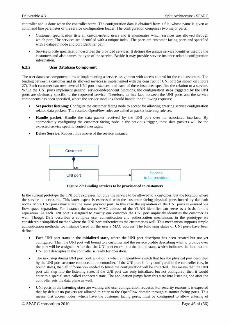
Deliverable 4.3 Split Architecture - SPARC
© SPARC consortium 2010 Page 46 of (66)
controller and is done when the controller starts. The configuration data is obtained from a file, whose name is given as
command line parameter of the service configuration loader. The configuration comprises two major parts:
Customer specification lists all customers/end users and it enumerates which services are allowed through
which port. The services are identified with a unique index. The ports are customer facing ports and specified
with a datapath node and port identifier pair.
Service profile specification describes the provided services. It defines the unique service identifier used by the
customers and also names the type of the service. Beside it may provide service instance related configuration
information.
6.2.2 User Database Component
The user database component aims at implementing a service assignment with access control for the end customers. The
binding between a customer and its allowed services is implemented with the construct of UNI port (as shown on Figure
27). Each customer can own several UNI port instances, and each of these instances specifies the relation to a service.
While the UNI ports implement generic, service-independent functions, the configuration steps triggered by the UNI
ports are obviously specific to the requested service. Therefore, an interface between the UNI ports and the service
components has been specified, where the service modules should handle the following requests:
Set packet listening: Configure the customer facing node to accept for allowing entering service configuration
related data packets. The resulted OpenFlow rules are called as packet listening rule set.
Handle packet: Handle the data packet received by the UNI port over its associated interface. By
appropriately configuring the customer facing node in the previous trigger, these data packets will be the
expected service specific control messages.
Delete Service: Request the remove of the service instance.
Customer
UNI portService
to be provided
0..N
Customer
UNI portService
to be provided
0..N
Figure 27: Binding services to be provisioned to customers
In the current prototype the UNI port expresses not only the service to be allowed to a customer, but the location where
the service is accessible. This latter aspect is expressed with the customer facing physical ports hosted by datapath
nodes. More UNI ports may share the same physical port. In this case the separation of the UNI ports is ensured via
flow space separation. For instance the source MAC address of the VLAN identifier can serve as a basis for the
separation. As each UNI port is assigned to exactly one customer the UNI port implicitly identifies the customer as
well. Though D3.2 describes a complex user authentication and authorization mechanism, in the prototype we
considered a simplified method where the UNI port authenticates the customer as well. This mechanism supports simple
authentication methods, for instance based on the user’s MAC address. The following states of UNI ports have been
defined:
Each UNI port starts in the initialized state, where the UNI port descriptor has been created but not yet
configured. Then the UNI port will bound to a customer and the service profile describing what to provide over
the port will be assigned. After that the UNI port enters into the bound state, which indicates the fact that the
UNI port descriptor in the controller is ready for operation.
The next step during UNI port configuration is when an OpenFlow switch that has the physical port described
by the UNI port structure connects to the controller. If the UNI port is fully configured in the controller (i.e., in
bound state), then all information needed to finish the configuration will be collected. This means that the UNI
port will step into the listening state. If the UNI port was only initialized but not configured, then it would
enter to a special state called connected state. The application jumps from this state into listening one after the
controller sets the data plane as well.
UNI ports in the listening state are waiting end user configuration requests. For security reasons it is expected
that by default no packets are allowed to enter to the OpenFlow domain through customer facing ports. This
means that access nodes, which have the customer facing ports, must be configured to allow entering of

Deliverable 4.3 Split Architecture - SPARC
© SPARC consortium 2010 Page 47 of (66)
configuration request encoding data packets on the customer facing ports. As these request packets can change
from service to service, the UNI port requests its associated service profile to implement the required flow
configuration. For example, allow entering PPPoE Discovery or DHCP discovery packets. These packets are
relayed to the controller, so one action is expected to be associated: sending the packets to the controller. Of
course this method does not preclude setting other configurations if the particular service requires it.
Any packets sent through the physical port associated to the UNI port will be sent to the controller. The user
database monitors these packets and passes them to the appropriate UNI port instance, which may relay them
to the assigned service instance. Then the UNI port proceeds toward the service configuration initiated state
and remains in this state if the associated service profile does not notify the UNI port about the success/failure
of service configuration. In case of successful configuration the UNI port enters to service deployed state.
Otherwise it falls back to listening state.
The service deployed state indicates that a service instance belonging to the service profile has been
successfully configured. Like in listening state, the configuration of the datapath elements are service specific,
therefore it is up to the associated service profile component how to perform these steps.
BOUND
CONNECTED
INITIALIZED LISTENINGSERVICE
DEPLOYED
SERVICE
INITIATED
Disconnect service
Trigger service
Failed
Successed
BOUND
CONNECTED
INITIALIZED LISTENINGSERVICE
DEPLOYED
SERVICE
INITIATED
BOUND
CONNECTED
INITIALIZED LISTENINGSERVICE
DEPLOYED
SERVICE
INITIATED
Disconnect service
Trigger service
Failed
Successed
Figure 28: UNI port states with major transitions.
6.3 DHCP Based Residential Service Component
The Broadband Forum’s TR-101 document specifies how residential IP service can be provided on top of an Ethernet
aggregation network. To attach end users, two major forwarding plane protocol stacks have been considered: PPPoE
and IPoE. The session control protocol to be used is influenced by the protocol stack: for the PPPoE stack its own
control protocols run, while for IPoE DHCP is deployed. During the prototyping activities, both stacks have been
considered. The current service component aims at implementing centralized control for the IPoE stack. An advantage
of the IPoE stack is that the standard OpenFlow matching structure supports it. This allows detaching the control
messages from the regular data stream, which finally allows the easy application of the split architecture. Furthermore,
there is no need for updating the OpenFlow switch model or the protocol itself.
Contrary to the TR-101, where the transport in the aggregation is Ethernet based, our prototype is based on MPLS in all
network segments. This means that the IPoE stack will be used only over the link between the end user and the
customer facing node (or Access Node). From that node, the end user IP packets are carried on the top of MPLS
towards the next service creation point. Considering the use case scenarios this subsequent service node resides in the
core network, i.e., it is not part of the OpenFlow controller aggregation. To sum up the following service creation
functions are programmed at the OpenFlow controller:
Processing service requests sent by the end user and performing end host configuration using DHCP protocol.
Initiate the configuration of transport connectivity between the end user facing access node and the next
service node.
Configuring IPoE-IPoMPLS interworking function (IWF) at the access node. It incorporates ARP message
handling.
The internal structure of the implemented component is depicted on Figure 29. The Service Profile module stores the
specific configuration data:
The transport IP address for the next-hop SCP. This address is required to define the remote node when an
end-to-end MPLS tunnel is requested.
The configuration of the customer’s end host. The prototype uses the following attributes to configure an end
host: IP address of the end host (with net mask) and the IP address of the default gateway.

Deliverable 4.3 Split Architecture - SPARC
© SPARC consortium 2010 Page 48 of (66)
Residential IPoE Service
Service ProfileService InstanceService InstanceService InstanceUNI
Port
Transport connection
request
End-to-end
Tunnel Manager
UNI signaling module
DHCP & ARP
Service Instance
IWF
configuration
NOX API
Residential IPoE Service
Service ProfileService InstanceService InstanceService InstanceUNI
Port
Transport connection
request
End-to-end
Tunnel Manager
UNI signaling module
DHCP & ARP
Service Instance
IWF
configuration
NOX API
Figure 29: Key functional elements of Residential Internet service module and their relation to surrounding
modules.
Beside being a configuration data store, this module implements the interface toward the UNI ports of the user database
component For “Set packet listening” request the access node is configured to relay any DHCP, ICMP and ARP packets
to the controller, which enters the node at the customer facing port. By setting this rule set the controller becomes able
to receive the service configuration requests initiated by the end user.
When the service profile module receives a handle packet request from an UNI port, it passes the packet to an
associated service instance module. If no such module exists, a new one is instantiated and bound to the UNI port. Note
that deleting an already created user service instance is not yet prototyped.
6.3.1 Service Instance Module
For each customer (UNI port) one service session is defined. The aim of the Service Instance module is to take care of
these sessions and manage the required configuration steps. To do so, it implements three sub-modules. The UNI
signalling module communicates with the end host: it processes the received packets, responds to the end host. Besides,
it triggers the configuration modules of the service instance. There are two such modules. The transport connection
requester module interacts with the end-to-end tunnel manager module by sending tunnel configuration request and
handling the response given by that component. The IWF configuration module, as its name implies, sets the
interworking function at the customer facing access node.
A new Service Instance Module is created by the Service Profile upon receiving a service request through a UNI port, to
which the module under creation will be attached. The state machine describing this module is depicted in Figure 30.
Tunnel CFG
Successes
End host
configured
Tunnel CFG
ResponseEnd host
configured
INITIALIZEDSERVER TUNNEL
REQUESTED
END HOST
CONFIGURED
SERVICE
DEPLOYED
Tunnel cfg or
end host cfg
fails
Tunnel cfg fails
End host
cfg fails
SERVICE CONFIG
FAILED
SERVER TUNNEL
DEPLOYED
Tunnel CFG
Successes
End host
configured
Tunnel CFG
ResponseEnd host
configured
INITIALIZEDSERVER TUNNEL
REQUESTED
END HOST
CONFIGURED
SERVICE
DEPLOYED
Tunnel cfg or
end host cfg
fails
Tunnel cfg fails
End host
cfg fails
SERVICE CONFIG
FAILED
SERVER TUNNEL
DEPLOYED
Figure 30: State machine representing the Service Instance Module for DHCP based residential internet access
component.

Deliverable 4.3 Split Architecture - SPARC
© SPARC consortium 2010 Page 49 of (66)
After initialization, the module retrieves the transport address of the local customer facing access node and the IP
address of the next service node and posts a transport connection request to the End-to-end Tunnel Manager module.
Then it enters into the server tunnel requested state. The transport tunnel manager module will respond with either the
details of the successfully configured connection or with an error. Depending on the content of the received answer the
module will step into one of the Server Tunnel Deployed or Server Configuration Failed states.
In parallel to the transport connection configuration, the UNI Signalling Module starts configuring the end host as well.
The UNI Signalling Module will notify the Session Instance Module when it finishes the configuration of the end host.
When both the end user configuration and the deployment of server tunnel are accomplished, the module will configure
the Interworking Function at the customer facing access node. Then all configurations are done and the module
proceeds to the service deployed state.
Note that current prototype version does not implement appropriate end host disconnection methods.
6.3.2 UNI Signalling Procedures
Besides setting up the service session in the OpenFlow domain the control application must configure the end host
appropriately. This comprises assigning an IP address to the end host interface that is connected to the OpenFlow
domain (with network mask), defining the IP address of the default next hop node and the Ethernet address of that node,
since IPoE stack is used between the end host and the access node and the end host should be configured what MAC
address is to be used to reach the default next hop node. In order to avoid impacting the end hosts, standardized
protocols are used: the DHCP for setting up IP addresses and ARP for signalling the MAC address.
The current prototype implements the DHCP server functions during the four-way handshake method as defined by
IETF RFC 2131 [32]. During this handshake the client detects the controller application as DHCP server. Then the
controller offers the IP configuration (IP address, net mask, default gateway) that is requested by the client. Note that
other functions, like disconnecting, IP address renewing and releasing have not been yet implemented.
DHCP however only configures the IP of the next hop node but it does not provide its MAC address. This latter
attribute is determined by the end host via sending ARP requests. These messages are also relayed to the controller that
will respond with a MAC address. This address is not necessarily one of the MAC addresses of the next hop node, it
may be fake. It can be done without any limitations when MAC address translation is implemented at the access node.
6.4 E-LINE Service Component
Our second prototyped service control component allows configuring point-to-point Ethernet Line service on the top of
MPLS forwarding (E-LINE or Virtual Private Wire Service, VPWS) between two end hosts attached to the OpenFlow
domain. Contrary to residential services, there is no standardized dynamic service creation enabling signalling scheme.
This means that such VPWS services are configured by the owner of the network by simply defining the association of
two customer facing ports to a VPWS instance. In the point of view of our prototype this means that we are free to
decide when to initiate the service creation after defining the VPWS instance. One can establish the VPWS service
when the associated customer facing ports are up, i.e., the nodes owning them connected to the controller. Another
extreme option is to wait with service creation until both end hosts become active. During prototyping we considered
this latter option mainly because this adds more control on when to create the tunnel and illustrate responsiveness of the
control scheme.
Therefore, we decomposed the functions into two modules (see. The VPWS Profile specifies one VPWS service (e.g.,
the two customer facing ports). It also implements the end host activity detection. The Service Instance is responsible
for setting up the VPWS instance.
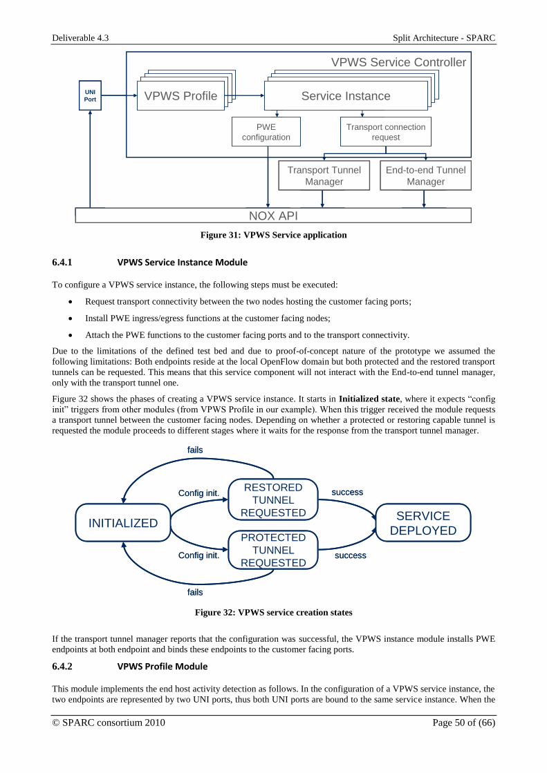
Deliverable 4.3 Split Architecture - SPARC
© SPARC consortium 2010 Page 50 of (66)
VPWS Service Controller
VPWS ProfileVPWS ProfileVPWS ProfileVPWS ProfileService InstanceService InstanceService InstanceUNI
Port
Transport connection
request
End-to-end Tunnel
Manager
Service Instance
PWE
configuration
NOX API
Transport Tunnel
Manager
VPWS Service Controller
VPWS ProfileVPWS ProfileVPWS ProfileVPWS ProfileService InstanceService InstanceService InstanceUNI
Port
Transport connection
request
End-to-end Tunnel
Manager
Service Instance
PWE
configuration
NOX API
Transport Tunnel
Manager
Figure 31: VPWS Service application
6.4.1 VPWS Service Instance Module
To configure a VPWS service instance, the following steps must be executed:
Request transport connectivity between the two nodes hosting the customer facing ports;
Install PWE ingress/egress functions at the customer facing nodes;
Attach the PWE functions to the customer facing ports and to the transport connectivity.
Due to the limitations of the defined test bed and due to proof-of-concept nature of the prototype we assumed the
following limitations: Both endpoints reside at the local OpenFlow domain but both protected and the restored transport
tunnels can be requested. This means that this service component will not interact with the End-to-end tunnel manager,
only with the transport tunnel one.
Figure 32 shows the phases of creating a VPWS service instance. It starts in Initialized state, where it expects “config
init” triggers from other modules (from VPWS Profile in our example). When this trigger received the module requests
a transport tunnel between the customer facing nodes. Depending on whether a protected or restoring capable tunnel is
requested the module proceeds to different stages where it waits for the response from the transport tunnel manager.
RESTORED
TUNNEL
REQUESTED
PROTECTED
TUNNEL
REQUESTED
INITIALIZEDSERVICE
DEPLOYED
Config init.
Config init.
success
success
fails
fails
RESTORED
TUNNEL
REQUESTED
PROTECTED
TUNNEL
REQUESTED
INITIALIZEDSERVICE
DEPLOYED
Config init.
Config init.
success
success
fails
fails
Figure 32: VPWS service creation states
If the transport tunnel manager reports that the configuration was successful, the VPWS instance module installs PWE
endpoints at both endpoint and binds these endpoints to the customer facing ports.
6.4.2 VPWS Profile Module
This module implements the end host activity detection as follows. In the configuration of a VPWS service instance, the
two endpoints are represented by two UNI ports, thus both UNI ports are bound to the same service instance. When the

Deliverable 4.3 Split Architecture - SPARC
© SPARC consortium 2010 Page 51 of (66)
UNI ports enter to listening state and request the VPWS Profile module to set the listening rule set it will simply
configure the access nodes to send all traffic entering at the customer facing port to the controller. So, the module will
receive any packets sent by the end hosts attached to the UNI ports belonging to the service profile. After receiving
packets from both end hosts the profile module will trigger the associated service instance one to start provisioning the
VPWS service.
Note, that this module does not provide methods for removing already deleted VPWS service instances.

Deliverable 4.3 Split Architecture - SPARC
© SPARC consortium 2010 Page 52 of (66)
7 “Floating BRAS” Integrated Prototype
7.1 Updated Control Plane Architecture
As discussed above, the Broadband Forum’s TR-101 document specifies two major forwarding plane protocol stacks,
the PPPoE stack and the IPoE stack for implementing residential internet services. In the point of view of SPARC a
significant difference between the two stacks is that while the standardized OpenFlow forwarding model implements
the IPoE encapsulation natively, it completely lacks the support of PPP and PPPoE. In an OpenFlow aggregation
domain, only specific nodes need to be capable of identifying and processing PPP flows besides the “standardized”
MPLS forwarding. The other nodes will not be updated.
These advanced PPP capable forwarding elements however do not implement the complex PPP session control
functions. Such functions placed at a controller dedicated to implementing the PPPoE functions of BRAS. In order to
implement some BRAS functionality a second controller has been developed. And some higher level service policing
functions are still deployed on the centralized controller. It introduced a split for PPPoE based residential internet
services in the control plane as shown in Figure 33.
DataPath
DataPath
DataPath
End user Transport node
+ BRASSCP
IP/MPLS IP/MPLS
SCPTransport nodes
BRAS
Server
Split
BRAS
MPLS OpenFlow controller with service apps
Transport control NNI Protocol Proxy
BRAS steering E-LINE service
“Embedded” control
“Centralized” control
DataPathDataPathDataPath
DataPathDataPathDataPath
DataPathDataPathDataPath
End user Transport node
+ BRASSCP
IP/MPLSIP/MPLSIP/MPLS IP/MPLSIP/MPLSIP/MPLS
SCPTransport nodes
BRASBRASBRAS
Server
Split
BRAS
MPLS OpenFlow controller with service apps
Transport control NNI Protocol Proxy
BRAS steering E-LINE service
MPLS OpenFlow controller with service apps
Transport control NNI Protocol Proxy
BRAS steering E-LINE service
“Embedded” control
“Centralized” control
Figure 33: Split control for Floating BRAS.
Though PPP and PPPoE migrated close to the service node, there are some functions that the centralized control
implements:
Management of the transport connection between a user facing Access Node and a BRAS node. Both the end
user and the BRAS implementation expect that the PPP frames are encapsulated in Ethernet frames (PPPoE).
Therefore, Ethernet connectivity is demanded, which is implemented with the help of using VPWS service
instances. For simplicity reasons, one service instance per end user is deployed; therefore, the configuration at
the BRAS and Access Node becomes trivial. At the Access Node, a one-to-one mapping between the VPWS
instance and the customer facing port is set; while at the BRAS side the MAC address of the end host is used
to select the PW channel. Note that the scalability of the service can be significantly improved by deploying
one VPWS instance per Access Node to BRAS pairs instead of one instance per end user. However, it does not
affect the overall provisioning procedures. So this update is considered as future work.
Management of the transport connection between a BRAS and the other service edge. The BRAS requires IP
connectivity in the upstream direction. However, these nodes can reside in the middle of the OpenFlow
domain, therefore the MPLS OpenFlow controller will take care of deploying end-to-end connections spanning
both the local OpenFlow aggregation domain and the IP/MPLS core network.
Assignment of service requests to a BRAS. Since a single service can be served by more than one BRAS
instance (one motivation for split BRAS concept) one should select a free BRAS to serve a new service
request. The prototype supports an on-the-fly BRAS selection mechanism based on priorities assigned to the
BRASs belonging to the service. The BRAS selection method is adjustable by administratively
enabling/disabling the BRAS instances for the selection method. More adequate solutions, for instance based
on collected statistics are not considered during prototyping.

Deliverable 4.3 Split Architecture - SPARC
© SPARC consortium 2010 Page 53 of (66)
Note, that in the current prototype the MPLS OpenFlow controller does not support the creation and detailed
configuration of the Split BRAS instances. Such features are considered as network management task and let for further
study.
7.2 BRAS-Aware Datapath
The BRAS-aware datapaths, as discussed above, are such datapaths of the MPLS OpenFlow domain that are also able
to implement some BRAS functions according to the Split BRAS concept. These extra functions are attached to the
aggregation switches. This observation led to the idea of keeping the two parts separately as shown in Figure 34.
Legend
Physical port
Node-internal virtual port
CTRL
BRAS
MPLS OpenFlow controller with service apps
Transport control NNI Protocol Proxy
BRAS steering E-LINE service
MPLS FWD
Legend
Physical port
Node-internal virtual port
CTRL
BRASBRASBRAS
MPLS OpenFlow controller with service apps
Transport control NNI Protocol Proxy
BRAS steering E-LINE service
MPLS OpenFlow controller with service apps
Transport control NNI Protocol Proxy
BRAS steering E-LINE service
MPLS FWDMPLS FWDMPLS FWD
Figure 34: BRAS-aware MPLS aggregation node structure in our prototype
All default functions that are needed in the MPLS OpenFlow aggregation domain are implemented by the MPLS
Forwarder part. Thus all physical interfaces of the node belong to this lower part. Beside, node internal virtual interfaces
are defined between the MPLS Forwarding and BRAS function implementing element. These interfaces are based on
Ethernet.
The control split discussed in previous section is mapped to this implementation as follows. The MPLS Forwarder part
is provisioned by the MPLS OpenFlow controller remotely and it implements the transport services between the BRAS
and the other service nodes. The BRAS part implements the per user function: PPP state handling, client packet routing
etc. The control of these functions is implemented locally.
7.3 Service Policing Components
To implement the above function, a BRAS Steering component has been specified as shown in Figure 35. It supports
several Split BRAS service instances: each is formed by a set of split BRASs (organized into BRAS Groups). The
required attributes of Split BRAS instances are collected in a descriptor:
Unique identifier and user-friendly name;
Priority that is taken into account during BRAS selection;
Ports that specify the identifier and ports of the transport datapath through which the Split BRAS instance can
reach the network. Two such descriptors are defined: one for the Upstream direction toward the next service
node and a customer facing one to reach customer facing Access Node;
Transport IP address of the next service node. This IP address is used during configuring the IP/MPLS tunnel
between the BRAS and the next service node.
Each BRAS group is responsible for keeping track of the PPP sessions belonging to the service instance. Each PPP
session is described with:
Its customer and BRAS facing endpoints;
The MAC addresses used by the end host of the BRAS;
The VPWS session established to implement the desired Ethernet connectivity in the MPLS aggregation
domain.

Deliverable 4.3 Split Architecture - SPARC
© SPARC consortium 2010 Page 54 of (66)
VPWS ProfileVPWS ProfileVPWS ProfileBRAS GroupService InstanceService InstanceService InstanceUNI
Port
Service InstanceService InstanceService InstanceUser Facing Port Upstream Port
VPWS Session
PPP Session
BRAS Descriptor
End-to-end Tunnel Manager
NOX API
VPWS ProfileVPWS ProfileVPWS ProfileBRAS GroupService InstanceService InstanceService InstanceUNI
Port
Service InstanceService InstanceService InstanceUser Facing Port Upstream Port
VPWS Session
PPP Session
BRAS Descriptor
End-to-end Tunnel Manager
NOX API
Figure 35: BRAS steering component.
7.3.1 Configuring Customer Facing Port
The UNI port, which represents an access point to a service described by a BRAS Group, requests the BRAS group to
configure the access node in the data plane to listen for control packets. In our case, these control packets are PPPoE
discovery packets. The flow rules matching on such packets are constructed by the BRAS group and downloaded when
a UNI port requests it.
7.3.2 User Session Creation
During user session creation the service policing applications act as a protocol proxy, i.e., the PPP endpoints, the end
host and the BRAS do not communicate with each other directly but only through the MPLS OpenFlow controller. This
proxy behaviour allows the controller to influence the BRAS selection as well as to establish the transport connections
between the service nodes on-the-fly. These actions are bound to the different PPPoE discovery handshake phases.
1. The end host starts the PPP session establishment with discovering the available BRAS nodes making use of
PPPoE Discovery Initialization (PADI) message. By catching the message the BRAS group module will select
one of its enabled member BRAS instances based on the assigned priorities. Then it creates a PPP session
descriptor as well. Finally, it relays the PADI message to the selected split BRAS instance through the MPLS
forwarder part of the BRAS.
2. The selected BRAS responds with a PPPoE Discovery Offer (PADO) message. The controller catches and
processes this message: it extends the PPP session descriptor with for example the MAC address used by the
BRAS. The PPPoE PADI package is then relayed to the end host.
3. The end host, after collecting PADO messages, targets one of the BRASs with a PPPoE Discovery Request
(PADR) message. The controller, upon receiving a PADR message, requests the configuration of Ethernet
connectivity between the end host facing the Access Node and the selected BRAS. For this purpose the VPWS
service infrastructure is used.
4. Once the Ethernet connectivity between the Access Node and the BRAS hosting one is deployed, the controller
forwards the PADR message, which triggers the Ethernet connectivity configuration, to the BRAS.
5. The BRAS responds with a PPPoE Discovery Session-confirmation (PADS). At this step, the MPLS transport
between the Access Node and the BRAS has been appropriately configured. So, the controller forwards this
message to the end host without any further actions.
After the PPPoE session discovery, the end host establishes the PPP session. Since there is a direct Ethernet
connectivity between the end host and the BRAS instance, the PPP session runs directly between the two nodes without
any interaction done at the MPLS OpenFlow controller.
7.3.3 Disconnecting User Session
Both endpoints of the PPP session can close the session. From the point of view of the service policing module the last
phase is important, when the PPPoE session is terminated using PPP Discovery Termination commands. In the current
implementation the PPP session related data structures are updated:

Deliverable 4.3 Split Architecture - SPARC
© SPARC consortium 2010 Page 55 of (66)
Triggers the remove of the Ethernet connectivity between the Access Node and the BRAS;
Removes the session related endpoint configuration at the Access Node and the BRAS;
Resets the PPP session descriptor.
Note, that the VPWS service module is responsible for the removal of the Ethernet connectivity.
7.3.4 Provisioning Upstream IP/MPLS from BRAS
Just like the Ethernet connectivity in downstream direction, a bidirectional IP/MPLS connection between the BRAS and
the service edge (or next-hop service nodes) are configured on-the-fly. The BRAS descriptor module takes care of the
upstream connection, since one such connection per BRAS instance is required. The upstream IP/MPLS connection is
requested from the NNI Protocol proxy module when the first PADI message, which will be relayed to the BRAS
instance, is received.
Note, that removal of the upstream IP/MPLS connection is not yet implemented in the current prototype.
7.4 BRAS Architecture Overview
A virtualized BRAS device provides the following high-level functionality:
Terminates PPPoE encapsulated PPP sessions initiated by the customer premises equipment (CPE);
Provides authentication and authorization services for the user session within PPP;
Forwards packets on layer 3 of the ISO/OSI model according to its local routing table;
Provides core side specific encapsulation methods, e.g. IP over MPLS over Ethernet or straight IP over
Ethernet.
The virtualized BRAS functionality is split into:
A BRAS control plane providing PPP session control and maintenance and L3 IPv4 forwarding functionality;
A BRAS OpenFlow 1.1 compliant data path element providing extended actions for
encapsulation/decapsulation services for PPPoE and IPoE.
Both BRAS control and data plane share a number of extended OpenFlow 1.1 actions for the PPP/PPPoE
encapsulation/decapsulation1. These extended actions include:
Table 4: Experimenter PPPoE actions
1 Note: A generic extension framework for defining arbitrary processing capabilities in data path elements has not been
defined yet. This is left as future work.
Extended Action Usage
PushPPPoE Adds a new PPPoE/PPP tag after a VLAN tag and before any MPLS tag
PopPPPoE Removes a PPPoE/PPP tag if existent
SetPPPoECode Sets the PPPoE tag code field
SetPPPoEType Sets the PPPoE tag type field
SetPPPoESessID Sets the PPPoE tag sessid field
SetPPPProt Sets the PPP tag protocol field

Deliverable 4.3 Split Architecture - SPARC
© SPARC consortium 2010 Page 56 of (66)
7.4.1 BRAS Control Plane
The BRAS control plane entity is responsible for the following tasks:
Initialization of the assigned data path element;
Controlling PPP sessions for attached customers including PPP internal authentication and authorization;
L3 forwarding and routing decisions in the control plane and setting appropriate Flow-Mod entries into the
data path flow table.
The BRAS control plane obtains all control packets from the PPPoE/PPP session and data packets, unless an
appropriate flow table entry exists. It consists of the following modules:
An Ethernet controller capable of forwarding packets on layer 2 and providing Ethernet (MAC based)
endpoints for communication services towards higher layers; and
An IP controller capable of forwarding packets on layer 3 and providing IP endpoints for communication
services towards higher layers;
A PPPoE/PPP adaptation/termination module loaded into the IP controller for managing customer PPP
sessions;
An IPoE adaptation/termination module loaded into the IP controller for sending/receiving traffic to/from the
access/aggregation default gateway.
The BRAS control plane entity is a modular implementation of a stack of controller entities. Due to migration
requirements the need for emulating legacy networking stacks will occur frequently in split architecture control planes.
The Revised OpenFlow Library (ROFL) provides an OpenFlow implementation capable of stacking OpenFlow
compliant proxy entities in a hierarchical manner. Both IP and Ethernet controller inherit functions from ROFL’s base
class called as “cctlelem”.
Both controller entities exchange messages using the OpenFlow protocol as defined by OpenFlow 1.1 using specific
extensions. Figure 36 depicts the core elements within the deployment.
Figure 36: Split BRAS functional modules
Both IP and Ethernet control entities share common functionality derived from a common base class. This base class
provides the following functions:

Deliverable 4.3 Split Architecture - SPARC
© SPARC consortium 2010 Page 57 of (66)
Hosting of specific adaptation/termination modules. The implementation provides modules for IP-over-
Ethernet and PPP-over-Ethernet currently that can be loaded in the IP controller;
Hosting of specific local transport endpoints that are exposing themselves as data path ports towards the next
higher layer instance.
A BRAS instance in the control plane is capable of controlling a single data path element and emulating BRAS
functionality on this element. Multiple BRAS instances may be collocated within a single program instance in order to
emulate multiple BRASs in parallel.
A BRAS instance may instantiate multiple access concentrator (AC) instances in parallel. Slicing among these instances
is achieved by assigning dedicated Ethernet (MAC) endpoints to each AC instance.
7.4.2 Logical Ethernet Controller (LEC)
The BRAS control plane contains a Logical Ethernet Controller (LEC) as its lowest layer entity. In general an Ethernet
controller provides the following services:
It is capable of forwarding packets based on layer 2 information, i.e. the Ethernet header;
It provides local L2 endpoints for Ethernet communication services2.
An Ethernet controller serves as lowest controller module in a stack of controller entities and is directly attached to a
single data path element. In this prototype implementation, a logical Ethernet controller controls a single data path
element. If multiple data path elements require L2 forwarding logic, several LEC instances must be instantiated in the
control plane.
An LEC may define local Ethernet transport endpoints for local communication needs. An Ethernet endpoint is defined
by a unique Ethernet (MAC) address and is bound to a physical or virtual port exposed by the attached data path
element. Valid data path ports for binding include all physical ports as well as logical ports like OFPP_CONTROLLER.
The binding of Ethernet endpoints and data path ports is a management task. The current implementation uses a
configuration file for defining static bindings between physical ports and L2 Ethernet transport endpoints.
An LEC may define an arbitrary number of local Ethernet transport endpoints, each being assigned a unique
MAC address.
Multiple local Ethernet transport endpoints may be bound to a single data path port.
Each local Ethernet transport endpoint is exposed as OpenFlow port towards the next higher layer (typically
IP) with a unique port number.
When a new local Ethernet transport endpoint is created, it will be registered as new physical port towards the next
higher layer entity using an OpenFlow Port-Status [ADD] message. In the same manner, removal of an Ethernet
transport endpoint results in an OpenFlow Port-Status [DELETE] message.
An LEC hosts a L2 forwarding logic and maintains a Forwarding Information Base (FIB) per virtual LAN identifier as
default. This forwarding logic emulates basic Ethernet switching behaviour. The L2 forwarding logic emulates a single
Ethernet switching device and may be replaced with more sophisticated Ethernet control logics, e.g. for controlling
multiple data path elements in a centralized manner using some form of path computation engine (CPE) or a TRILL like
implementation for DCB scenarios. For current the BRAS prototype the L2 switching functionality has been disabled,
as the BRAS provides L3 forwarding services only.
Local Ethernet endpoints adapt upstream and downstream passing OpenFlow messages according to the endpoint’s
local state, i.e.
In an upstream OF message (e.g. OF-Packet-In), the packet’s Ethernet destination address must be identical to
the one assigned to the local transport endpoint. A packet gets dropped otherwise as it is not destined to the
local endpoint.
In a downstream OF message (e.g. OF-Packet-Out), the packet’s Ethernet source address will be replaced by
the MAC address assigned to this Ethernet endpoint. Any Ethernet source address of the higher layer will be
lost intentionally.
In an upstream OF message the OF-incoming port parameter will be adjusted to the local Ethernet transport
endpoint’s port number registered with the higher layer.
2 Note: An Ethernet OAM module according to Y.1731 is left as future work and will be implemented as termination
module for the Ethernet controller.

Deliverable 4.3 Split Architecture - SPARC
© SPARC consortium 2010 Page 58 of (66)
In a downstream OF message the OF-match structure received from the higher layer will be changed
accordingly, e.g. “ActionOutput” instances will be updated with the port number of the physical data path port
that this local Ethernet transport endpoint is bound to.
When a packet is received on a local Ethernet transport endpoint, it is sent upwards towards the next higher layer entity.
A local transport endpoint always sends a packet with a plain Ethernet header and its payload to the higher layer, any
L2 specific tags are removed (e.g. VLAN, q-in-q, PBB tags). This behaviour is required in order to offer the higher
layer entity a common packet format. A local transport endpoint may include additional adaptation functions (like
assigning specific VLAN tags). In this case such a specific endpoint is exposed as new port towards the higher layer.
Please note: MPLS is considered as a L2.5 technology and will not be removed from the payload field by the Ethernet
controller.
7.4.3 Logical IPv4 Controller (LICv4)
An IPv4 controller provides the following services:
It is capable of forwarding packets based on layer 3 information, i.e. the IPv4 header;
It provides local L3 endpoints for IP communication services.
An IPv4 controller uses the communication services offered by the underlying controller instance, i.e. an Ethernet
controller instance. The Ethernet controller acts as data path element with respect to the LIC and exposes its local
Ethernet transport endpoints as ports towards the higher layer. Status changes of local Ethernet transport endpoints are
signaled using standard OpenFlow OF-Port-Status messages, i.e. the Ethernet controller may signal creation,
destruction, or state changes of one of its local Ethernet endpoints towards the LIC.
An LIC may define local IP (L3) transport endpoints for higher layer entities similar to the L2 endpoints defined by the
Ethernet controller. In the BRAS prototype L3 endpoints are not used, as there are no higher layer entities.
An LIC provides IPv4 L3 forwarding services, i.e. it hosts a routing information base (RIB) and a forwarding
information base (FIB). The current implementation also provides an IP configuration module that stores assigned IP
addresses, network masks, peer address (if applicable), and default gateway (if any). The IP forwarding engine creates
based on received OpenFlow Packet-In messages flow mod entries and sends these downwards along the stack of
controllers.
The LIC provides an implementation of the Address Resolution Protocol (ARP) according to RFC 826.
The LIC provides support for Path MTU discovery according to RFC 1191.
All routes within the LIC are currently implemented as static routes. Support for dynamic updating of routes via OSPF,
IS-IS or other means is not available.
An LIC expects IP frames encapsulated within plain Ethernet frames according to RFC 894. An adaptation/termination
module must remove any additional tags before sending the packet upwards to the LIC. The LIC sends IP datagrams
encapsulated within an Ethernet frame and sets the destination MAC address for point-to-multipoint capable interfaces
and the Ethernet type field to 0x0800.
7.4.4 Adaptation and Termination Functions
The BRAS is characterized by two adaptation/termination functions:
The PPPoE/PPP module provides adaptation/termination functionality towards the access/aggregation side. It
uses plain Ethernet transport for sending and receiving PPPoE frames and exposes IP-over-Ethernet frames to
the IP forwarding engine.
The IPoE module provides an IP-over-Ethernet module. It uses plain Ethernet transport for sending and
receiving IPv4 frames and exposes IP-over-Ethernet frames to the IP forwarding engine.
These modules define the glue between Ethernet and IP controller. In the BRAS prototype both controller modules and
both adaptation/termination modules are separate classes that can be extended with additional functionality (e.g. Path
MTU discovery in the IP forwarding engine) without affecting other modules.
7.4.5 BRAS Data Path Element
The BRAS data path entity is responsible for the following tasks:
Providing extended OpenFlow parser functionality for PPPoE/PPP for determining control and data frames
within PPP;
Providing extended processing capabilities for encapsulating/decapsulating IP frames within a PPP container.

Deliverable 4.3 Split Architecture - SPARC
© SPARC consortium 2010 Page 59 of (66)
The BRAS data path element is programmed by the BRAS control plane entity, so that PPP control frames are
redirected to the BRAS control plane and data frames are decapsulated and sent upstream towards the gateway and vice
versa. The BRAS data path element is an OpenFlow 1.1 compliant data path element including MPLS functionality as
defined by the OpenFlow specification version 1.1. However, it does not provide the extended MPLS features (e.g.
OAM) as defined (see Deliverable 3.2) and implemented within project SPARC (see Deliverable D4.2). The data path
element contains an extended parser and processing engine for handling PPPoE/PPP frames and the extended actions as
defined in the introduction section of section 7.4.
7.4.6 PPPoE/PPP Adaptation Function
The PPPoE/PPP adaptation/termination module provides a PPP over Ethernet implementation according to RFC 2516
and hosts a class for encapsulating or connecting to PPP implementations. Currently this uses the pppd implementation
from Carnegie Mellon University used on most Linux distributions. The PPP implementation must comprise all PPP
protocol phases including LCP, authentication/authorization, and IPv4CP. The PPP module may connect to an AAA
server. However, in the prototype this feature has not been activated yet.
A PPPoE/PPP module defines a point-to-point communication abstraction. Both Ethernet source and destination
address are replaced for outgoing packets sent by the IP forwarding engine. A single PPPoE/PPP module is capable of
hosting up to 65535 PPPoE sessions within a single instance. Multiple PPPoE/PPP modules can be instantiated in
parallel within a controller module, but must bind to different physical ports (though the current prototype is not able to
detect an error condition when two PPPoE/PPP instances bind to the same physical port.) Binding a PPPoE/PPP module
to a physical port assigns the underlying local Ethernet transport endpoint’s MAC address to the PPPoE/PPP module,
i.e. this step defines the access concentrator’s (AC) MAC address.
The PPPoE/PPP module provides means to adapt/change OpenFlow messages along their way through the stack, i.e. all
OpenFlow match structures and instructions/actions are changed accordingly. This includes actions for pushing/popping
PPPoE and PPP tags to/from the Ethernet frame and setting fields like the PPPoE session identifier. The PPP
termination functionality located in the Link Control Protocol (LCP) via ECHO request/reply exchanges is still located
in the BRAS controller. Moving this termination functions to the data path as a generic processing logic is left as future
work.
7.4.7 IPoE Adaptation Function
The IPoE adaptation/termination module provides an IP over Ethernet implementation according to RFC 894. An IPoE
module provides a point-to-multipoint communication abstraction as expected by IP, i.e. the higher layer IP entity must
define the Ethernet destination address as intended endpoint of the Ethernet transport service. The source Ethernet
address is defined by the physical port the IPoE instance is bound to.
7.5 Split BRAS Workflow
The initialization comprises two steps:
Local Ethernet transport endpoint creation;
PPPoE/PPP module instantiation.
A PPPoE/PPP session is established in four phases by a split BRAS entity’s PPPoE/PPP module:
PPPoE discovery and session creation;
PPP session setup;
Registration of new adapted Ethernet endpoint within IP forwarding engine;
Creation of FlowMod entries by the IP forwarding engine and installation in the data path.
7.5.1 Ethernet Endpoint Instantiation
The following steps occur when a data path element connects to a BRAS control plane entity:
A BRAS compliant data path with the defined extended action set for OF1.1 connects to a split BRAS control
entity. The BRAS control plane checks existence of all required PPPoE/PPP related extended actions;
The Ethernet controller learns from the data path the set of physical ports available;
The Ethernet controller creates a set of endpoints, at least one for a PPPoE/PPP module connected towards
CPEs and one connected towards the router connecting core and aggregation domain, and binds these

Deliverable 4.3 Split Architecture - SPARC
© SPARC consortium 2010 Page 60 of (66)
endpoints to underlying physical ports. In the BRAS prototype implementation, the endpoints adopt the
physical port’s MAC addresses, but other MAC addresses may be used as well;
All created Ethernet endpoints are exposed to the IP controller entity as new physical ports;
In the current prototype, the Ethernet controller registers the entire flow space at the underlying data path
element, i.e. all OpenFlow communication takes place with the BRAS prototype instance. Note that this may
be limited to specific protocols like PPPoE and IPv4, so that other controller entities might control other parts
of the overall flow space.
The Ethernet controller will check incoming OpenFlow messages from the data path against the registered local
Ethernet transport endpoints. If one is matching with the Ethernet destination address, the OpenFlow message is handed
over to the endpoint for further processing, i.e. it is sent upwards to the IP controller entity. Packets with non-matching
addresses are dropped.
The Ethernet controller will send Ethernet frames with a broadcast destination address to all active local Ethernet
transport endpoints.
7.5.2 PPPoE Module Instantiation
The following steps occur when a PPPoE/PPP module is instantiated within an IP controller:
The PPPoE/PPP module is loaded after instantiation into the IP controller;
The PPPoE/PPP module is bound to a local Ethernet transport endpoint as exposed by the underlying Ethernet
controller and uses the MAC address assigned to this Ethernet transport endpoint;
The binding is a management task and must be done on a physical port that directs traffic to a DSLAM or
MSAN, i.e. is directed towards CPEs. In the BRAS prototype this is static configuration obtained from the
configuration file at start-up.
The PPPoE/PPP module registers parts of the overall flow space with the surrounding IP controller: the flow
space comprises the Ethernet endpoints MAC address and the PPPoE Ethernet types:
o Example: 00:11:11:11:11:11 / 0x8863 and 00:11:11:11:11:11 / 0x8864
7.5.3 IPoE Module Instantiation
The following steps occur when an IPoE module is instantiated within an IP controller:
The IPoE module is loaded after instantiation into the IP controller;
The IPoE module is bound to a local Ethernet transport endpoint as exposed by the underlying Ethernet
controller and uses the MAC address assigned to this Ethernet transport endpoint;
The binding is a management task and must be done on a physical port that directs traffic to the aggregation
domain’s gateway, i.e. is directed towards core network. In the BRAS prototype this is static configuration
obtained from the configuration file at start-up.
The IPoE module registers a single adapted Ethernet transport endpoint in the IP forwarding engine via an
OpenFlow Port-Status-Add message. The message contains endpoint specific information including the
assigned IP address. This is an extension to the existing OpenFlow protocol specification.
7.5.4 IP Forwarding Engine Instantiation
The IP forwarding instance hosts a routing information base that is filled via its management interface at start-up. The
default route is obtained from the configuration file as static parameter. The IP forwarding engine is fully operational
afterwards. The forwarding information base is initially empty and hosts IP address to Ethernet transport
domain/Ethernet addresses in the following.
7.5.5 PPPoE discovery stage
The PPPoE discovery stage works as follows (refer to RFC 2516 for a general introduction for PPPoE):
The CPE pppoe instance sends a PPPoE PADI frame for discovery available access concentrators to the
Ethernet broadcast address.
The data path receives the frame. As there is no flow table entry, the packet will be sent to the control plane
within an OpenFlow Packet-In message.

Deliverable 4.3 Split Architecture - SPARC
© SPARC consortium 2010 Page 61 of (66)
The Ethernet controller identifies the packet as a broadcast frame and sends it to all local Ethernet transport
endpoints bound to the physical port the frame was received on. In the BRAS prototype that is exactly one
Ethernet endpoint.
The Ethernet transport endpoint sends the received OpenFlow Packet-In message up to the IP controller.
The IP controller checks for the flow space registrations of all active adaptation/termination modules. As there
is only a single registration by the PPPoE/PPP module for this Ethernet transport endpoint and PPPoE Ethernet
types 0x8863/0x8864, the PADI is sent to the PPPoE module.
The PPPoE module validates correctness of the PADI frame and generates a PADO offer frame. It sets the
Ethernet source destination address and copies mandatory PPPoE tags like Relay-Session-ID and Host-Uniq
tags.
The PADO packet is sent to the requesting CPE via an OpenFlow Packet-Out message.
7.5.6 PPPoE Session Establishment
The CPE pppoe instance selects from the set of received PADO offers one based on local policy.
The CPE pppoe instance sends a PPPoE PADR frame for establishing a session to the selected access
concentrator’s unicast MAC address.
The data path receives the frame. As there is no flow table entry, the packet will be sent to the control plane
within an OpenFlow Packet-In message.
The Ethernet controller identifies the frame to be of type unicast and searches for a local Ethernet transport
endpoint claiming the PADR’s destination MAC address as local address. If none is found, the packet gets
dropped. If one is found, the Packet-In is send to this Ethernet endpoint.
The Ethernet transport endpoint sends the received OpenFlow Packet-In message up to the IP controller.
Figure 37: PPP session negotiation within the split BRAS
The IP controller checks for the flow space registrations of all active adaptation/termination modules. As there
is only a single registration by the PPPoE/PPP module for this Ethernet transport endpoint and PPPoE Ethernet
types 0x8863/0x8864, the PADR is sent to the PPPoE module.
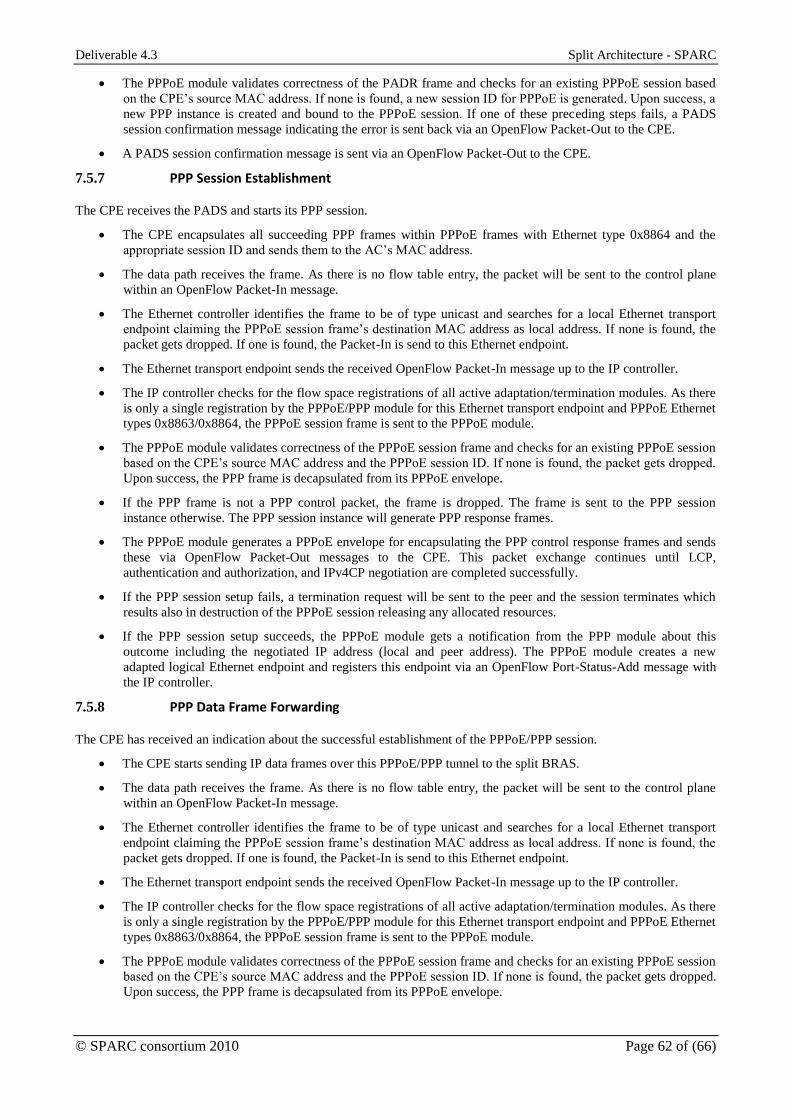
Deliverable 4.3 Split Architecture - SPARC
© SPARC consortium 2010 Page 62 of (66)
The PPPoE module validates correctness of the PADR frame and checks for an existing PPPoE session based
on the CPE’s source MAC address. If none is found, a new session ID for PPPoE is generated. Upon success, a
new PPP instance is created and bound to the PPPoE session. If one of these preceding steps fails, a PADS
session confirmation message indicating the error is sent back via an OpenFlow Packet-Out to the CPE.
A PADS session confirmation message is sent via an OpenFlow Packet-Out to the CPE.
7.5.7 PPP Session Establishment
The CPE receives the PADS and starts its PPP session.
The CPE encapsulates all succeeding PPP frames within PPPoE frames with Ethernet type 0x8864 and the
appropriate session ID and sends them to the AC’s MAC address.
The data path receives the frame. As there is no flow table entry, the packet will be sent to the control plane
within an OpenFlow Packet-In message.
The Ethernet controller identifies the frame to be of type unicast and searches for a local Ethernet transport
endpoint claiming the PPPoE session frame’s destination MAC address as local address. If none is found, the
packet gets dropped. If one is found, the Packet-In is send to this Ethernet endpoint.
The Ethernet transport endpoint sends the received OpenFlow Packet-In message up to the IP controller.
The IP controller checks for the flow space registrations of all active adaptation/termination modules. As there
is only a single registration by the PPPoE/PPP module for this Ethernet transport endpoint and PPPoE Ethernet
types 0x8863/0x8864, the PPPoE session frame is sent to the PPPoE module.
The PPPoE module validates correctness of the PPPoE session frame and checks for an existing PPPoE session
based on the CPE’s source MAC address and the PPPoE session ID. If none is found, the packet gets dropped.
Upon success, the PPP frame is decapsulated from its PPPoE envelope.
If the PPP frame is not a PPP control packet, the frame is dropped. The frame is sent to the PPP session
instance otherwise. The PPP session instance will generate PPP response frames.
The PPPoE module generates a PPPoE envelope for encapsulating the PPP control response frames and sends
these via OpenFlow Packet-Out messages to the CPE. This packet exchange continues until LCP,
authentication and authorization, and IPv4CP negotiation are completed successfully.
If the PPP session setup fails, a termination request will be sent to the peer and the session terminates which
results also in destruction of the PPPoE session releasing any allocated resources.
If the PPP session setup succeeds, the PPPoE module gets a notification from the PPP module about this
outcome including the negotiated IP address (local and peer address). The PPPoE module creates a new
adapted logical Ethernet endpoint and registers this endpoint via an OpenFlow Port-Status-Add message with
the IP controller.
7.5.8 PPP Data Frame Forwarding
The CPE has received an indication about the successful establishment of the PPPoE/PPP session.
The CPE starts sending IP data frames over this PPPoE/PPP tunnel to the split BRAS.
The data path receives the frame. As there is no flow table entry, the packet will be sent to the control plane
within an OpenFlow Packet-In message.
The Ethernet controller identifies the frame to be of type unicast and searches for a local Ethernet transport
endpoint claiming the PPPoE session frame’s destination MAC address as local address. If none is found, the
packet gets dropped. If one is found, the Packet-In is send to this Ethernet endpoint.
The Ethernet transport endpoint sends the received OpenFlow Packet-In message up to the IP controller.
The IP controller checks for the flow space registrations of all active adaptation/termination modules. As there
is only a single registration by the PPPoE/PPP module for this Ethernet transport endpoint and PPPoE Ethernet
types 0x8863/0x8864, the PPPoE session frame is sent to the PPPoE module.
The PPPoE module validates correctness of the PPPoE session frame and checks for an existing PPPoE session
based on the CPE’s source MAC address and the PPPoE session ID. If none is found, the packet gets dropped.
Upon success, the PPP frame is decapsulated from its PPPoE envelope.
Deliverable 4.3 Split Architecture - SPARC
© SPARC consortium 2010 Page 63 of (66)
As the authentication state of the session is –Authenticated–, the following policy is applied to received PPP
frames: when a PPP control packet was found, it is send to the PPP control instance; in case of a PPP data
packet the IP payload is extracted, a pseudo Ethernet header is prepended using the Ethernet addresses of the
PPPoE/PPP session frame, and the new adapted Ethernet/IP frame is sent to the IP controller’s forwarding
engine.
7.5.9 IP Forwarding
The IP forwarding engine receives a (pseudo constructed) IP-over-Ethernet frame either from a CPE after PPPoE/PPP
adaptation or from the core gateway.
The IP payload is validated.
The next hop for the destination IP address based on the local routing information base is determined. If the
next hop is a point-to-point interface (downstream towards the CPE), a FlowMod entry is generated including
OpenFlow match structure and instructions/actions definitions.
The FlowMod entry is handed over to the controller base class which filters the match structure as well as the
instructions/actions definitions through the active adaptation/termination modules. Here, match and
instructions/actions are adapted accordingly. The adapted FlowMod entry is sent down the stack to the
Ethernet controller.
If the next hop determined for the destination IP address is a point-to-multipoint interface (like an IP-over-
Ethernet interface), the local forwarding information base is queried for a mapping of next-hop-IP address to
Ethernet transport address. If none is found in the FIB, an ARP resolution is started and the frame is queued for
later treatment. Upon reception of an appropriate ARP reply, the FlowMod entry generation continues for all
queued data frames. If the packet’s drop timer on the data path expires earlier than an ARP reply leads to a new
FlowMod entry, the initial packet in this communication might get lost.
The forwarding engine instructs the IP controller to send the new FlowMod entry down the stack. The IP
controller inherits functionality from the cctlelem base class, which filters the new FlowMod entry through all
involved adaptation/termination modules (based on OpenFlow match structure and instructions/actions
definitions).
The PPPoE/PPP module adds actions as required to the instructions’ ActionLists:
o ActionPushPPPoE / ActionPopPPPoE for adding/removing a joint PPPoE/PPP tag
o ActionSetPPPoESessID/Code/Type/PPPProt for setting the relevant PPPoE/PPP tag fields
Once all involved adaptation/termination modules has adapted the FlowMod entry, it travels further down the
stack. Upon reception by the Ethernet controller, it is filtered through all Ethernet transport endpoint that are
referred to by the OpenFlow match structure or the instructions/actions definitions.
The Ethernet endpoints set the Ethernet source addresses accordingly. Any existing source address will be
replaced.
After this filtering has been concluded, the FlowMod entry is sent to the data path element where it is actually
installed in the flow table.
Succeeding data frames will be handled based on this new FlowMod entry directly on the data path.
A pair of two FlowMod entries is installed per customer: one for upstream and one for downstream direction,
respectively.

Deliverable 4.3 Split Architecture - SPARC
© SPARC consortium 2010 Page 64 of (66)
Figure 38: IP routing and associated FlowMod generation
Deliverable 4.3 Split Architecture - SPARC
© SPARC consortium 2010 Page 65 of (66)
References
[1] Information Technology Infrastructure Library (ITIL), available online
http://www.itil-officialsite.com/home/home.asp
[2] N. Leymann, “Seamless MPLS architecture”, IETF MPLS WG draft draft-ietf-mpls-seamless-mpls-01,
March, 2012.
[3] NOX OpenFlow Controller, http://noxrepo.org/
[4] Beacon, https://openflow.stanford.edu/display/Beacon/Home
[5] Maestro, http://www.cs.rice.edu/~eugeneng/papers/TR10-11.pdf
[6] Trema, http://trema.github.com/trema/
[7] “IEEE Standard for Local and Metropolitan Area Networks – Station and Media Access Connectivity
Discovery”, IEEE Std. 802.1ab, September, 2009.
[8] “OAM functions and mechanisms for Ethernet”, ITU-T Y.1731, July, 2011.
[9] D. Katz, K. Kompella and D. Yeung, ” Traffic Engineering (TE) Extensions to OSPF Version 2”,
IETF RFC 3630, September, 2003.
[10] L. Anderson et. al., ”LDP Specification”, IETF RFC 5036, October 2007.
[11] D. Awduche et. al., ”RSVP-TE: Extensions to RSVP for LSP Tunnels”, IETF RFC 3209, December
2001.
[12] T. Bates et. al., ”Multiprotocol Extensions for BGP-4”, IETF RFC 2858, June, 2000.
[13] Stanford OpenFlow reference implementation, [Online] Last accessed September 2012
http://www.openflow.org/wp/downloads/
[14] OpenVSwitch homepage, [Online] Last accessed September 2012 http://openvswitch.org/
[15] Ericsson MPLS extensions to OpenFlow version 0.8.9, [Online] Last accessed September 2012
http://www.openflow.org/wk/index.php/OpenFlowMPLS
[16] D. Katz and D. Ward, “Bidirectional Forwarding Detection (BFD)”, IETF RFC 5880, June 2010,
http://tools.ietf.org/rfc/rfc5880
[17] A. Fulignoli, S. Boutros and M. Vigoureux, “Proactive Connectivity Verification, Continuity Check,
and Remote Defect Indication for the MPLS Transport Profile”, IETF individual draft, March, 2010,
http://tools.ietf.org/html/draft-asm-mpls-tp-bfd-cc-cv-02
[18] M. Bocci et al., “MPLS Generic Associated Channel”, IETF RFC 5586, June 2009,
http://tools.ietf.org/html/rfc5586
[19] Google Protocol Buffers, [Online] Last accessed September 2012
https://developers.google.com/protocol-buffers/
[20] S. Bryant and P. Pate “Pseudo Wire Emulation Edge-to-Edge (PWE3) Architecture”, IETF RFC 3985,
March 2005, http://tools.ietf.org/rfc/rfc3985.txt
[21] S. Bryant et al., “Pseudowire Emulation Edge-to-Edge (PWE3) Control Word for Use over an MPLS
PSN” IETF RFC 4385, February 2006, http://tools.ietf.org/rfc/rfc4385.txt
[22] Quagga: http://www.quagga.net/
[23] `Dragon GMPLS stack: http://dragon.maxgigapop.net/
[24] G2MPLS: http://www.ist-phosphorus.eu/software.php?id=g2mpls
[25] K. Shiomoto, “Framework for MPLS-TE to GMPLS Migration”, IETF RFC 5145, March 2008.
[26] J.P. Lang et. al., ” RSVP-TE Extensions in Support of End-to-End Generalized Multi-Protocol Label
Switching (GMPLS) Recovery”, IETF RFC 4872, May 2007.
[27] ENVI: http://www.openflow.org/wp/gui/
[28] LAVI: http://www.openflow.org/wk/index.php/LAVI
[29] D. Staessens, S. Sharma, D. Colle, M. Pickavet, P. Demeester, "Software defined networking: Meeting
carrier grade requirements", Proc. 18th IEEE Workshop on Local & Metropolitan Area Networks
(LANMAN), 13-14 Oct. 2011.

Deliverable 4.3 Split Architecture - SPARC
© SPARC consortium 2010 Page 66 of (66)
[30] James Kempf, et al., ”Scalable Fault Monitoring for OpenFlow”, in proceedings SDN'12: Workshop
on Software Defined Networks, Ottawa, CA, June 15, 2012.
[31] http://www.kernel.org/doc/Documentation/networking/tuntap.txt
[32] R. Droms, “Dynamic Host Configuration Protocol”, IETF-RFC 2131, March, 1997.
[33] D. Crockford, “The application/json Media Type for JavaScript Object Notation (JSON)”, IETF-RFC
4627, July 2006.
[34] J. W. Suurballe and R. E. Tarjan, “A quick method for finding shortest pairs of disjoint paths”,
Networks, Vol.14, pp 325-336.


![[MPLS Configuration Guide] - D-Link Academyacademy.dlink.com/temp/exam_Issue/230/MPLS Configuration Guide… · MPLS Configuration Guide Multiprotocol Label Switching (MPLS) MPLS](https://img.dokumen.tips/doc/110x75/5a815ac47f8b9ada388cfeea/mpls-configuration-guide-d-link-configuration-guidempls-configuration-guide.jpg)