Embed Size (px)
Citation preview

SPARC Enterprise M8000/M9000 Servers
Installation Guide
Part No.: E27052-02,Manual Code: C120-E328-11ENOctober 2012

Copyright © 2007, 2012, Fujitsu Limited. All rights reserved. Oracle and/or its affiliates provided technical input and review on portions of this material.Oracle and/or its affiliates and Fujitsu Limited each own or control intellectual property rights relating to products and technology described in this document, and such products, technology and this document are protected by copyright laws, patents, and other intellectual property laws and international treaties.This document and the product and technology to which it pertains are distributed under licenses restricting their use, copying, distribution, and decompilation. No part of such product or technology, or of this document, may be reproduced in any form by any means without prior written authorization of Oracle and/or its affiliates and Fujitsu Limited, and their applicable licensors, if any. The furnishings of this document to you does not give you any rights or licenses, express or implied, with respect to the product or technology to which it pertains, and this document does not contain or represent any commitment of any kind on the part of Oracle or Fujitsu Limited, or any affiliate of either of them.This document and the product and technology described in this document may incorporate third-party intellectual property copyrighted by and/or licensed from the suppliers to Oracle and/or its affiliates and Fujitsu Limited, including software and font technology.Per the terms of the GPL or LGPL, a copy of the source code governed by the GPL or LGPL, as applicable, is available upon request by the End User. Please contact Oracle and/or its affiliates or Fujitsu Limited. This distribution may include materials developed by third parties.Parts of the product may be derived from Berkeley BSD systems, licensed from the University of California. UNIX is a registered trademark in the U.S. and in other countries, exclusively licensed through X/Open Company, Ltd.Oracle and Java are registered trademarks of Oracle and/or its affiliates. Fujitsu and the Fujitsu logo are registered trademarks of Fujitsu Limited. All SPARC trademarks are used under license and are registered trademarks of SPARC International, Inc. in the U.S. and other countries. Products bearing SPARC trademarks are based upon architectures developed by Oracle and/or its affiliates. SPARC64 is a trademark of SPARC International, Inc., used under license by Fujitsu Microelectronics, Inc. and Fujitsu Limited. Other names may be trademarks of their respective owners.United States Government Rights - Commercial use. U.S. Government users are subject to the standard government user license agreements of Oracle and/or its affiliates and Fujitsu Limited and the applicable provisions of the FAR and its supplements.Disclaimer: The only warranties granted by Oracle and Fujitsu Limited, and/or any affiliate of either of them in connection with this document or any product or technology described herein are those expressly set forth in the license agreement pursuant to which the product or technology is provided. EXCEPT AS EXPRESSLY SET FORTH IN SUCH AGREEMENT, ORACLE OR FUJITSU LIMITED, AND/OR THEIR AFFILIATES MAKE NO REPRESENTATIONS OR WARRANTIES OF ANY KIND (EXPRESS OR IMPLIED) REGARDING SUCH PRODUCT OR TECHNOLOGY OR THIS DOCUMENT, WHICH ARE ALL PROVIDED AS IS, AND ALL EXPRESS OR IMPLIED CONDITIONS, REPRESENTATIONS AND WARRANTIES, INCLUDING WITHOUT LIMITATION ANY IMPLIED WARRANTY OF MERCHANTABILITY, FITNESS FOR A PARTICULAR PURPOSE OR NONINFRINGEMENT, ARE DISCLAIMED, EXCEPT TO THE EXTENT THAT SUCH DISCLAIMERS ARE HELD TO BE LEGALLY INVALID. Unless otherwise expressly set forth in such agreement, to the extent allowed by applicable law, in no event shall Oracle or Fujitsu Limited, and/or any of their affiliates have any liability to any third party under any legal theory for any loss of revenues or profits, loss of use or data, or business interruptions, or for any indirect, special, incidental or consequential damages, even if advised of the possibility of such damages.DOCUMENTATION IS PROVIDED “AS IS” AND ALL EXPRESS OR IMPLIED CONDITIONS, REPRESENTATIONS AND WARRANTIES, INCLUDING ANY IMPLIED WARRANTY OF MERCHANTABILITY, FITNESS FOR A PARTICULAR PURPOSE OR NON-INFRINGEMENT, ARE DISCLAIMED, EXCEPT TO THE EXTENT THAT SUCH DISCLAIMERS ARE HELD TO BE LEGALLY INVALID.
PleaseRecycle

Copyright © 2007, 2012, Fujitsu Limited. Tous droits réservés. Oracle et/ou ses sociétés affiliées ont fourni et vérifié des données techniques de certaines parties de ce composant.Oracle et/ou ses sociétés affiliées et Fujitsu Limited détiennent et contrôlent chacune des droits de propriété intellectuelle relatifs aux produits et technologies décrits dans ce document. De même, ces produits, technologies et ce document sont protégés par des lois sur le copyright, des brevets, d’autres lois sur la propriété intellectuelle et des traités internationaux.Ce document, le produit et les technologies afférents sont exclusivement distribués avec des licences qui en restreignent l’utilisation, la copie, la distribution et la décompilation. Aucune partie de ce produit, de ces technologies ou de ce document ne peut être reproduite sous quelque forme que ce soit, par quelque moyen que ce soit, sans l’autorisation écrite préalable d’Oracle et/ou ses sociétés affiliées et de Fujitsu Limited, et de leurs éventuels bailleurs de licence. Ce document, bien qu’il vous ait été fourni, ne vous confère aucun droit et aucune licence, expresses ou tacites, concernant le produit ou la technologie auxquels il se rapporte. Par ailleurs, il ne contient ni ne représente aucun engagement, de quelque type que ce soit, de la part d’Oracle ou de Fujitsu Limited, ou des sociétés affiliées de l’une ou l’autre entité.Ce document, ainsi que les produits et technologies qu’il décrit, peuvent inclure des droits de propriété intellectuelle de parties tierces protégés par copyright et/ou cédés sous licence par des fournisseurs à Oracle et/ou ses sociétés affiliées et Fujitsu Limited, y compris des logiciels et des technologies relatives aux polices de caractères.Conformément aux conditions de la licence GPL ou LGPL, une copie du code source régi par la licence GPL ou LGPL, selon le cas, est disponible sur demande par l’Utilisateur final. Veuillez contacter Oracle et/ou ses sociétés affiliées ou Fujitsu Limited. Cette distribution peut comprendre des composants développés par des parties tierces.Des parties de ce produit peuvent être dérivées des systèmes Berkeley BSD, distribués sous licence par l’Université de Californie. UNIX est une marque déposée aux États-Unis et dans d’autres pays, distribuée exclusivement sous licence par X/Open Company, Ltd.Oracle et Java sont des marques déposées d’Oracle Corporation et/ou de ses sociétés affiliées. Fujitsu et le logo Fujitsu sont des marques déposées de Fujitsu Limited. Toutes les marques SPARC sont utilisées sous licence et sont des marques déposées de SPARC International, Inc., aux États-Unis et dans d’autres pays. Les produits portant la marque SPARC reposent sur des architectures développées par Oracle et/ou ses sociétés affiliées. SPARC64 est une marque de SPARC International, Inc., utilisée sous licence par Fujitsu Microelectronics, Inc. et Fujitsu Limited. Tout autre nom mentionné peut correspondre à des marques appartenant à d’autres propriétaires.United States Government Rights - Commercial use. U.S. Government users are subject to the standard government user license agreements of Oracle and/or its affiliates and Fujitsu Limited and the applicable provisions of the FAR and its supplements.Avis de non-responsabilité : les seules garanties octroyées par Oracle et Fujitsu Limited et/ou toute société affiliée de l’une ou l’autre entité en rapport avec ce document ou tout produit ou toute technologie décrits dans les présentes correspondent aux garanties expressément stipulées dans le contrat de licence régissant le produit ou la technologie fournis. SAUF MENTION CONTRAIRE EXPRESSÉMENT STIPULÉE DANS CE CONTRAT, ORACLE OU FUJITSU LIMITED ET LES SOCIÉTÉS AFFILIÉES À L’UNE OU L’AUTRE ENTITÉ REJETTENT TOUTE REPRÉSENTATION OU TOUTE GARANTIE, QUELLE QU’EN SOIT LA NATURE (EXPRESSE OU IMPLICITE) CONCERNANT CE PRODUIT, CETTE TECHNOLOGIE OU CE DOCUMENT, LESQUELS SONT FOURNIS EN L’ÉTAT. EN OUTRE, TOUTES LES CONDITIONS, REPRÉSENTATIONS ET GARANTIES EXPRESSES OU TACITES, Y COMPRIS NOTAMMENT TOUTE GARANTIE IMPLICITE RELATIVE À LA QUALITÉ MARCHANDE, À L’APTITUDE À UNE UTILISATION PARTICULIÈRE OU À L’ABSENCE DE CONTREFAÇON, SONT EXCLUES, DANS LA MESURE AUTORISÉE PAR LA LOI APPLICABLE. Sauf mention contraire expressément stipulée dans ce contrat, dans la mesure autorisée par la loi applicable, en aucun cas Oracle ou Fujitsu Limited et/ou l’une ou l’autre de leurs sociétés affiliées ne sauraient être tenues responsables envers une quelconque partie tierce, sous quelque théorie juridique que ce soit, de tout manque à gagner ou de perte de profit, de problèmes d’utilisation ou de perte de données, ou d’interruptions d’activités, ou de tout dommage indirect, spécial, secondaire ou consécutif, même si ces entités ont été préalablement informées d’une telle éventualité.LA DOCUMENTATION EST FOURNIE « EN L’ÉTAT » ET TOUTE AUTRE CONDITION, DÉCLARATION ET GARANTIE, EXPRESSE OU TACITE, EST FORMELLEMENT EXCLUE, DANS LA MESURE AUTORISÉE PAR LA LOI EN VIGUEUR, Y COMPRIS NOTAMMENT TOUTE GARANTIE IMPLICITE RELATIVE À LA QUALITÉ MARCHANDE, À L’APTITUDE À UNE UTILISATION PARTICULIÈRE OU À L’ABSENCE DE CONTREFAÇON.


Contents
Preface ix
1. Installation Workflow 1–1
2. Preparing to Install the System 2–1
2.1 Safety Precautions 2–1
2.2 Before Installing the Server 2–2
2.2.1 Checking Environmental Requirements 2–2
2.2.2 Facility Power Requirements 2–4
2.2.2.1 Power Supply Connection Specifications 2–4
2.2.2.2 Power Supply Requirements 2–6
2.2.2.3 Grounding 2–11
2.2.3 Checking the Installation Location 2–12
2.2.4 Rack Space for the M8000 Server 2–12
2.3 Requirements for Server Installation 2–13
3. Installing the Server 3–1
3.1 Checking Components 3–1
3.2 Securing the Base Cabinet 3–2
3.3 Connecting the Expansion Cabinet and Power Cabinet 3–3
3.3.1 Connecting the Optional Expansion Cabinet 3–5
v

3.3.2 Connecting the Power Cabinet 3–10
3.3.2.1 Connecting the Base Cabinet and Power Cabinet 3–10
3.3.2.2 Connecting the M9000 Server Expansion Cabinet and the Power Cabinet 3–20
3.4 Connecting Cables 3–24
3.4.1 Connecting the power cords 3–24
3.4.1.1 Single-Phase Power Feed 3–25
3.4.1.2 Three Phase Power Feed 3–31
3.4.2 Connecting a UPS Unit 3–32
3.4.3 Cable Connection Between the Base and Expansion Cabinets of the M9000 Server 3–34
3.4.3.1 Connecting Cables Between XSCF Units 3–35
3.4.3.2 Connecting Cables Between CLKUs 3–35
3.4.3.3 Connecting Cables Between XB Units 3–37
3.4.4 Connecting the Administration Console 3–46
3.5 Checking the Input Power 3–48
3.5.1 Single-Phase Power 3–49
3.5.2 Three-Phase Power 3–49
3.6 Setting and Checking the Required Information for the Servers 3–49
3.6.1 Switch On the Main Line Switches 3–50
3.6.2 Logging Into the XSCF Shell 3–51
3.6.3 Initializing the XSCF 3–52
3.6.4 Checking for a Capacity on Demand (COD) Board 3–53
3.7 Powering On/Off the System 3–53
3.7.1 Powering On the System 3–54
3.7.2 Confirming XSCF Redundancy 3–55
3.7.3 Connecting an Ethernet Port 3–57
3.7.4 Verifying the Configuration 3–58
3.7.5 Checking the Dual-Power Feed 3–59
vi SPARC Enterprise M8000/M9000 Servers Installation Guide • October 2012

3.7.6 Powering Off the System 3–59
3.8 Connecting Additional Peripheral Devices 3–60
4. Connecting Your Domains to the Network and Running the Oracle VTS Software4–1
4.1 Network Connection Outline 4–1
4.2 Connecting the System to Each Network 4–4
4.3 Verifying a Network Connection 4–6
4.4 Starting the Oracle Solaris Operating System 4–6
4.5 Verifying the Operation Using the Oracle VTS Software 4–8
A. System Views A–1
A.1 M8000 Server Views A–2
A.2 M9000 Server Views A–4
A.3 Power Cabinet Views A–6
A.3.1 M8000 Server + Power Cabinet A–6
A.3.2 M9000 Server + Power Cabinet A–8
A.4 Operator Panel Overview A–10
B. Troubleshooting B–1
B.1 Actions to Take for Common Problems B–1
B.2 Using Troubleshooting Commands B–2
B.2.1 Using the showhardconf Command B–3
B.2.2 Using the showlogs Command B–8
B.2.3 Using the showstatus Command B–8
B.2.4 Using the fmdump Command B–9
B.2.4.1 Using the fmdump -V Command B–9
B.2.4.2 Using the fmdump -e Command B–10
B.2.5 Using the fmadm faulty Command B–10
B.2.5.1 Using the fmadm config Command B–10
Contents vii

B.2.6 Using the fmstat Command B–11
B.3 Traditional Oracle Solaris Troubleshooting Commands B–11
B.3.1 iostat Command B–11
B.3.1.1 iostat Command Options B–12
B.3.2 prtdiag Command B–13
B.3.2.1 prtdiag Command Options B–13
B.3.3 prtconf Command B–15
B.3.3.1 prtconf Command Options B–15
B.3.4 netstat Command B–16
B.3.4.1 netstat Command Options B–16
B.3.5 ping Command B–17
B.3.5.1 ping Command Options B–18
B.3.6 ps Command B–18
B.3.6.1 ps Command Options B–19
B.3.7 prstat Command B–19
B.3.7.1 prstat Command Options B–20
viii SPARC Enterprise M8000/M9000 Servers Installation Guide • October 2012

Preface
This manual explains how to install and set up the SPARC Enterprise M8000/M9000 servers from Oracle and Fujitsu. The manual assumes that system components have already been unpacked. References herein to the M8000 server or M9000 server are references to the SPARC Enterprise M8000 or SPARC Enterprise M9000 server.
This chapter includes the following sections:■ “Audience” on page ix■ “Related Documentation” on page x■ “Text Conventions” on page xi■ “Notes on Safety” on page xi■ “Syntax of the Command-Line Interface (CLI)” on page xii■ “Documentation Feedback” on page xii
AudienceThe manual is written for the authorized service personnel and field engineers who perform maintenance work on the system.
ix

Related DocumentationAll documents for your sever are available online at the following locations:
The following table lists titles of related documents.
Documentation Link
Sun Oracle software-related manuals (Oracle Solaris OS, and so on)
http://www.oracle.com/documentation
Fujitsu documents http://www.fujitsu.com/sparcenterprise/manual/
Oracle M-series server documents http://www.oracle.com/technetwork/documentation/sparc-mseries-servers-252709.html
Related SPARC Enterprise M8000/M9000 Servers Documents
SPARC Enterprise M8000/M9000 Servers Site Planning Guide
SPARC Enterprise M8000/M9000 Servers Getting Started Guide*
SPARC Enterprise M8000/M9000 Servers Overview
SPARC Enterprise M3000/M4000/M5000/M8000/M9000 Servers Important Legal and Safety Information *
SPARC Enterprise M8000/M9000 Servers Safety and Compliance Guide
External I/O Expansion Unit Safety and Compliance Guide
SPARC Enterprise M8000/M9000 Servers Unpacking Guide*
SPARC Enterprise M8000/M9000 Servers Installation Guide
SPARC Enterprise M8000/M9000 Servers Service Manual
External I/O Expansion Unit Installation and Service Manual
SPARC Enterprise M3000/M4000/M5000/M8000/M9000 Servers Administration Guide
SPARC Enterprise M3000/M4000/M5000/M8000/M9000 Servers XSCF User’s Guide
SPARC Enterprise M3000/M4000/M5000/M8000/M9000 Servers XSCF Reference Manual
SPARC Enterprise M4000/M5000/M8000/M9000 Servers Dynamic Reconfiguration (DR) User’s Guide
SPARC Enterprise M4000/M5000/M8000/M9000 Servers Capacity on Demand (COD) User’s Guide
SPARC Enterprise M3000/M4000/M5000/M8000/M9000 Servers Product Notes†
SPARC Enterprise M8000/M9000 Servers Product Notes
External I/O Expansion Unit Product Notes
SPARC Enterprise M3000/M4000/M5000/M8000/M9000 Glossary
x SPARC Enterprise M8000/M9000 Servers Installation Guide • October 2012

Text ConventionsThis manual uses the following fonts and symbols to express specific types of information.
Notes on SafetyRead the following documents thoroughly before using or handling any SPARC Enterprise M8000/M9000 server.■ SPARC Enterprise M3000/M4000/M5000/M8000/M9000 Servers Important Legal and
Safety Information ■ SPARC Enterprise M8000/M9000 Servers Safety and Compliance Guide
* This is a printed document.
† Beginning with the XCP 1100 release.
Font/Symbol Meaning Example
AaBbCc123 What you type, when contrasted with on-screen computer output.This font represents the example of command input in the frame.
XSCF> adduser jsmith
AaBbCc123 The names of commands, files, and directories; on-screen computer output.This font represents the example of command output in the frame.
XSCF> showuser -PUser Name: jsmithPrivileges: useradm
auditadm
Italic Indicates the name of a reference manual, a variable, or user-replaceable text.
See the SPARC Enterprise M3000/M4000/M5000/M8000/M9000 Servers XSCF User’s Guide.
" " Indicates names of chapters, sections, items, buttons, or menus.
See Chapter 2, "System Features."
Preface xi

Syntax of the Command-Line Interface (CLI)The command syntax is as follows:■ A variable that requires input of a value must be put in Italics.■ An optional element must be enclosed in [].■ A group of options for an optional keyword must be enclosed in [] and delimited by |.
Documentation FeedbackIf you have any comments or requests regarding this document, go to the following websites:■ For Oracle users:
http://www.oracle.com/goto/docfeedback
Include the title and part number of your document with your feedback:
SPARC Enterprise M8000/M9000 Servers Installation Guide, part number E27052-01
■ For Fujitsu users:
http://www.fujitsu.com/global/contact/computing/sparce_index.html
xii SPARC Enterprise M8000/M9000 Servers Installation Guide • October 2012

CHAPTER 1
Installation Workflow
This chapter describes the work required in the workflow from the server installation to hardware operation verification. For details, see TABLE 1-1.
TABLE 1-1 Installation Workflow
Installation Stage Workflow Task
Preliminary checks Before installing the server, check the environmental requirements. See Section 2.2.1, “Checking Environmental Requirements” on page 2-2.
↓ Check the input power supply specifications for the server, and prepare an appropriate power supply. See Section 2.2.2, “Facility Power Requirements” on page 2-4.
↓ Check the service areas of the server. See Section 2.2.3, “Checking the Installation Location” on page 2-12.
↓ Prepare the required tools and instruments for the server installation. See Section 2.3, “Requirements for Server Installation” on page 2-13.
Installing and connecting the servers
Check components and accessories. See Section 3.1, “Checking Components” on page 3-1.
↓ If the server includes a SPARC Enterprise M9000 server expansion cabinet, or the power cabinet, combine this component and the base cabinet. See Section 3.3, “Connecting the Expansion Cabinet and Power Cabinet” on page 3-3.
↓ Connect the input power supply cables, UPS cables, and console cable. See Section 3.4, “Connecting Cables” on page 3-24.
↓ Before connecting the power supply unit, verify the input voltage. See Section 3.5, “Checking the Input Power” on page 3-48.
Verifying settings and powering on the server
Access the XSCF Shell to verify the public key of the XSCF host, register a user account, and perform the time setting and altitude setting. See Section 3.6, “Setting and Checking the Required Information for the Servers” on page 3-49.
↓ Power on the system using the operator panel. Check the server configuration and verify the operation in dual feed mode before powering off the system. See Section 3.7, “Powering On/Off the System” on page 3-53.
1-1

↓ Connect the Ethernet port of the XSCF unit to the system control network. Verify that you can log into the XSCF Shell through the LAN. See Section 3.7.3, “Connecting an Ethernet Port” on page 3-57.
↓ Add peripheral devices. See Section 3.8, “Connecting Additional Peripheral Devices” on page 3-60.
Configuring the test environment and verifying the server operation
Connect the LAN port of the IOUA to the user network. See Section 4.2, “Connecting the System to Each Network” on page 4-4.
↓ Verify network connections. See Section 4.3, “Verifying a Network Connection” on page 4-6.
↓ Start the Oracle Solaris Operating System. See Section 4.4, “Starting the Oracle Solaris Operating System” on page 4-6.
↓ Install the Oracle VTS software and use it to verify the hardware operation. See Section 4.5, “Verifying the Operation Using the Oracle VTS Software” on page 4-8.
→ From here, perform the setup required for the operation of the system. See the SPARC Enterprise M3000/M4000/M5000/M8000/M9000 Servers Administration Guide.
TABLE 1-1 Installation Workflow (Continued)
Installation Stage Workflow Task
1-2 SPARC Enterprise M8000/M9000 Servers Installation Guide • October 2012

CHAPTER 2
Preparing to Install the System
This chapter describes preparations for installation.■ Section 2.1, “Safety Precautions” on page 2-1■ Section 2.2, “Before Installing the Server” on page 2-2■ Section 2.3, “Requirements for Server Installation” on page 2-13
2.1 Safety PrecautionsObserve the following precautions when setting up the high-end servers.
Otherwise, the equipment may be damaged or a malfunction may result.■ Do not block any ventilation holes.■ Do not install the server in a location exposed to direct sunlight or near a device that may
become hot.■ Do not install the server in a location that has a lot of dust or that is exposed to corrosive
gases or air with a high salt concentration.■ Do not install the server in a location exposed to frequent vibrations. Install the server on
a flat and level surface.■ The grounding resistance must not be greater than 10Ω. The grounding method varies by the
building where you install the server. Make sure that the facility administrator or a qualified electrician verifies the grounding method for the building and performs the grounding work.
■ Be sure each grounding wire used for the server is used exclusively. Also be sure to observe the precautions, warnings, and notes on handling shown on the equipment.
■ Do not place cables under the equipment or have cables stretched tight. Also, do not disconnect a power cord from the equipment while its power is on.
2-1

■ When disconnecting a LAN cable, you may not be able to reach the connector lock with your fingers. If that is the case, press the connector lock with a flathead screwdriver to disconnect the cable. You could damage the PCI card if you force your fingers into the gap rather than use a flathead screwdriver.
■ Do not place anything on the server or perform any work directly above it.■ Do not allow the ambient temperature to rise sharply in winter. Such a sudden temperature
change would cause condensation to form inside the server. Allow for a sufficient warm-up period prior to server operation.
■ Do not install the server near a copy machine, air conditioner, welding machine, or any other loud equipment generating electronic noise.
■ Take measures to prevent static electricity from being generated at the installation location. Note especially that static electricity is likely to be generated on carpets, and this could lead to a malfunction.
■ Confirm that the supply voltage and frequency match the electrical ratings indicated on the equipment.
■ Do not insert anything into any opening in the equipment. The equipment contains high-voltage parts. If a metal object or another conductor were inserted into an opening in the equipment, it may cause a short circuit that could cause fire, electric shock, or equipment damage.
■ For details on maintenance of the server, contact a certified service engineer.
2.2 Before Installing the ServerBefore installing the server, you must know the system configuration and obtain all the prerequisite information for system installation. For details, see “Before Setting Up the System,” in the SPARC Enterprise M8000/M9000 Servers Site Planning Guide.
2.2.1 Checking Environmental RequirementsThis section describes the ambient environmental requirements included in the installation specifications of the server.
The environmental requirements vary depending on the sea level altitude at the installation site, as indicated in TABLE 2-1.
2-2 SPARC Enterprise M8000/M9000 Servers Installation Guide • October 2012

TABLE 2-1 Ambient Environmental Requirements
Operating Range Non-Operating Range Optimum
Ambient temperature
5°C to 32°C(41°F to 89.6°F)
Unpacked:0°C to 50°C (32°F to 122°F)Packed:-20°C to 60°C(-4°F to 140°F)
21°C to 23°C(70°F to 74°F)
Relative humidity *
* There is no condensation regardless of the temperature and humidity.
20% RH to 80% RH to 93% RH 45% RH to 50% RH
Altitude restriction †
† All altitudes are above sea level.
3,000 m (10,000 ft) 12,000 m (40, 000 ft)
Temperature conditions
5°C to 32°C (41°F to 89.6°F) at an installation altitude ranging from 0 to less than 1500 m (4921 ft) above sea level5°C to 30°C (41°F to 86°F) at an installation altitude ranging from 1500 m (4921 ft) to less than 2000 m (6562 ft) above sea level5°C to 28°C (41°F to 82.4°F) at an installation altitude ranging from 2000 m (6562 ft) to less than 2500 m (8202 ft) above sea level5°C to 26°C (41°F to 78.8°F) at an installation altitude ranging from 2500 m (8202 ft) to 3000 m (9843 ft) above sea level
Chapter 2 Preparing to Install the System 2-3

TABLE 2-2 lists recommended temperatures and humidities for computer rooms.
2.2.2 Facility Power RequirementsThis section describes the M8000/M9000 Server's power supply connection specifications, power supply requirements, and the configurations of power distribution.
The two types of power supply that the M8000/M9000 servers can use are single-phase power supplies and three-phase power supplies. Redundant power cords are supported only on servers with the dual power feed option installed. By default, the dual power feed option is installed on servers that use three-phase power supplies.
2.2.2.1 Power Supply Connection SpecificationsTABLE 2-3 lists power cord connection specifications for single-phase power supplies.
TABLE 2-2 Recommended Temperatures and Humidities for Computer Rooms
Air Conditioning Setup
Near the Underfloor Air Outlet Detection and Regulation Point
RemarksTemperature Humidity Temperature Humidity
°C °F % °C °F %
Direct blowing or duct blowing
- - - 24±2 75±4 45±5 -
Underfloor ventilation
18±1 64±2 65±5 Target temperature 24°C
Target temperature 75°F
About 45% at 24 °C
The room temperature and humidity fluctuate, without control, according to the thermal load in the room.
Direct blowing or duct blowing and underfloor ventilation combined
18±1 64±2 65±5 24±2 75±4 45±5 -
2-4 SPARC Enterprise M8000/M9000 Servers Installation Guide • October 2012

TABLE 2-3 Power Supply Connection Specifications
Name DestinationPowerCord Length*
* The power cord length is the length from the cord port on the cabinet to the outlet plug.
Plug Type Number of Plugs‡
‡ A primary power feed server without the dual power feed option does not have a redundant power cord. All power cords in the primary power feed server must be kept connected and under power.
Outlet in Facility**
M8000 Server
Japan 3.0 m (9.8 ft) 30 A-250 V 3P, locking type plug(NEMA L6-30P)
3 (single-power feed)6 (dual-power feed)
30 A-250 V 3P, locking type (NEMA L6-30R)Embedded type: 3320-L6 <American Denki>Exposed type: 3321-L6 <American Denki>
North America, General Overseas
3.0 m (9.8 ft) NEMA L6-30P†
† The plugs for the North America and general overseas markets may be replaced locally as required. Make sure that the facility administrator or a qualified electrical engineer performs the replacement work.
3 (single-power feed)6 (dual-power feed)
NEMA L6-30R (North America only)
Europe 3.0 m (9.8 ft) EN60309 (32 A) 3 (single-power feed)6 (dual-power feed)
EN60309 (32 A)
M9000 Server
Japan 3.0 m (9.8 ft) 30A-250V 3P, locking type plug(NEMA L6-30P)
Base cabinet5 (single-power feed)10 (dual-power feed)Base cabinet + expansion cabinet10 (single-power feed)20 (dual-power feed)
30 A-250 V 3P, locking type (NEMA L6-30R)Embedded type: 3320-L6 <American Denki>Exposed type: 3321-L6 <American Denki>
North America
3.0 m (9.8 ft) NEMA L6-30P† Base cabinet5 (single-power feed)10 (dual-power feed)Base cabinet + expansion cabinet10 (single-power feed)20 (dual-power feed)
NEMA L6-30R (North America only)
General Overseas
3.0 m (9.8 ft) EN60309 (32A) Base cabinet5 (single-power feed)10 (dual-power feed)Base cabinet + expansion cabinet10 (single-power feed)20 (dual-power feed)
EN60309 (32 A)
Chapter 2 Preparing to Install the System 2-5

2.2.2.2 Power Supply RequirementsThe following figures show the input power systems for the high-end servers:■ Single-phase power supply system (M8000 server) (FIGURE 2-1)■ Single-phase power supply system (M9000 server) (FIGURE 2-2)■ Three-phase delta power supply system (FIGURE 2-3)■ Three-phase star power supply system (FIGURE 2-4)
Single-Phase Power Supply
**For the servers that have the plug with lock function, confirm that a 30A overcurrent protection device is available outside the server. If one is not available, prepare an external 30A overcurrent protection that can be achieved by means of no-fuse breakers (NFBs) or fuses. The plug with lock function refers to plugs other than grounding-type ones with two parallel blades, such as the NEMA L6-30, L6-20, L6-15, and L5-15.
TABLE 2-4 Single-Phase Power Supply
Device name Voltage [V] Phases Frequency
M8000/M9000 200 to 240 VAC±10% Single 50/60 Hz +2% to -4%
Power Cabinet*
* Power is supplied with at least one or two power cabinets.
200 to 240 VAC±10% Single 50/60 Hz +2% to -4%
Rack-mountable dual-power feed†
† The rack-mountable dual-power feed (DPF) is a device that enables the M8000 server to have a redundant power source (single-phase dual-power feed).
200 to 240 VAC±10% Single 50/60 Hz +2% to -4%
2-6 SPARC Enterprise M8000/M9000 Servers Installation Guide • October 2012

FIGURE 2-1 Single-Phase Power Supply System (M8000 Server)
Note – (1) To connect multiple input cords of the server to the customer's distribution panel, the input cords must be independently connected to outlets on the basis of a one-to-one correspondence as shown in FIGURE 2-1.
Note – (2) Connect the power feed A and the power feed B (for dual-power feed) to a separate AC power supply from each other.
Power feed APower feed B
Dual-power feed system
distribution boarddistribution board
(Note 1)
(Note 2)
Chapter 2 Preparing to Install the System 2-7

FIGURE 2-2 Single-Phase Power Supply System (M9000 Server)
Note – (1) To connect multiple input cords of the server to the customer's distribution panel, the input cords must be independently connected to outlets on the basis of a one-to-one correspondence as shown in FIGURE 2-2.
Note – (2) Connect the power feed A and the power feed B (for dual-power feed) to a separate AC power supply from each other.
ExpansionDual-power Dual-power
Power feed B Power feed A Power feed A Power feed B
feed system cabinet feed system
distribution board distribution board feed distribution distribution board board
Base cabinet
(Note 1)
(Note 2)
2-8 SPARC Enterprise M8000/M9000 Servers Installation Guide • October 2012

Three-Phase Delta Power Input
Note – For three-phase power feed, the power cabinet is mandatory equipment and the dual-power feed function is included in the standard configuration.
FIGURE 2-3 Three-Phase Delta Power Supply System - Rear View
TABLE 2-5 Three-Phase Delta Power Input
Device Name Voltage [V] Phases Frequency
M8000 + Power Cabinet 200 to 240 VAC±10% Three-phase delta 50/60 Hz +2% to -4%
M9000 + Power Cabinet 200 to 240 VAC±10% Three-phase delta 50/60 Hz +2% to -4%
Power feed B Power feed A distribution board distribution board
Input #1 Input #0
(Note)
Power cabinetM8000/M9000
Chapter 2 Preparing to Install the System 2-9

Note – Connect the power feed A and the power feed B (for dual-power feed) to a separate AC power supply from each other.
Three-Phase Star Power Input
Note – For a three-phase power feed, the power cabinet is mandatory equipment and the dual-power feed function is included in the standard configuration.
TABLE 2-6 Three-Phase Star Power Input
Device Name Voltage [V] Phases Frequency
M8000 + Power Cabinet 380 to 415 VAC±10% Three-phase star 50/60 Hz +2% to -4%
M9000 + Power Cabinet 380 to 415 VAC±10% Three-phase star 50/60 Hz +2% to -4%
2-10 SPARC Enterprise M8000/M9000 Servers Installation Guide • October 2012

Chapter 2 Preparing to Install the System 2-11
FIGURE 2-4 Three-Phase Star Power Supply System - Rear View
Note – Connect the power feed A and the power feed B (for dual-power feed) to a separate AC power supply from each other.
2.2.2.3 Grounding
Grounding for Single-phase Power Supply
The single-phase power supply M8000/M9000 servers are shipped with a grounded (three-wire) power cord.
The power cord must always be connected to a power outlet that has a grounding receptacle. When you connect the power cord to the power outlet, the server grounding completes.
Power feed B Power feed A
Power cabinetM8000/M9000
distribution board distribution board
Input #1 Input #0
(Note)

Grounding for Three-phase Power Supply
The power cable is not supplied with the three-phase power supply M8000/M9000 servers.
Ensure that the power cable wiring includes a ground wire from the distribution board to the terminal board of the power cabinet, as a part of the on-site electrical work.
For the installation positions, see FIGURE 3-27 and FIGURE 3-28.
This server allows the use of grounding wire with another grounding wire for shared grounding; however, the grounding methods may vary by the building where the system is installed.
Check the related standards in order to use the correct grounding method.
The grounding resistance must not be greater than 10 Ω. The grounding method varies by the building where you install the server. Make sure that the facility administrator or a qualified electrical engineer verifies the grounding method for the building and performs the grounding work.
2.2.3 Checking the Installation LocationFor the high-end servers installation, secure a service area (maintenance area) that is large enough for each system (cabinet).
For details, see the SPARC Enterprise M8000/M9000 Servers Site Planning Guide.
2.2.4 Rack Space for the M8000 ServerA 12-pitch sized rack space (12U) is provided in the upper part of the cabinet of the M8000 server.
In this rack space for a M8000 server, the rack-mountable dual-power feed uses 6U of rack space, and the rest of the space can be used for the customer external devices.
2-12 SPARC Enterprise M8000/M9000 Servers Installation Guide • October 2012

FIGURE 2-5 Rack Space for the M8000 Server
2.3 Requirements for Server InstallationThis section lists the items and information required for installation work. Prepare these items in advance.■ Administration console
obtain any of the following from the customer
■ ASCII terminal■ Workstation■ Terminal server (or patch panel connected to the terminal server)■ PC
■ XSCF-LAN configuration information
See the SPARC Enterprise M8000/M9000 Servers Site Planning Guide.
Rack-mountable
Rack space
Empty space
dual-power feed
Chapter 2 Preparing to Install the System 2-13

■ Console configuration information
See the SPARC Enterprise M8000/M9000 Servers Site Planning Guide.
■ No. 2 Phillips screwdriver
Used to remove and mount power cord covers.
■ Flathead screwdriver
Used to secure cables between cabinets if the expansion cabinet of the M9000 server is mounted.
■ Torque screwdriver and slotted bit (0.2 Nm; 2.0 kgfcm).
Used to secure the clock cables between the cabinets if the expansion cabinet of the M9000 server is mounted.
■ 30-mm wrench
Used to secure the server legs.
■ 13-mm nut driver
Used to connect the optional expansion cabinet of the M9000 server.
■ Torque wrench and socket for 13 mm torque wrench (8.24 N·m; 84 kgf·cm).
Used to connect the power cabinet.
■ Antistatic wrist strap
When the expansion cabinet of the M9000 server is attached, two persons are required for the installation and two wrist straps are required for them.
■ Multimeter
Used to check the input AC voltage power cord.
■ Shipping list
Used to confirm high-end servers configuration.
2-14 SPARC Enterprise M8000/M9000 Servers Installation Guide • October 2012

CHAPTER 3
Installing the Server
This chapter explains how to make preparations for connecting the server to a network:■ Section 3.1, “Checking Components” on page 3-1■ Section 3.2, “Securing the Base Cabinet” on page 3-2■ Section 3.3, “Connecting the Expansion Cabinet and Power Cabinet” on page 3-3■ Section 3.4, “Connecting Cables” on page 3-24■ Section 3.5, “Checking the Input Power” on page 3-48■ Section 3.6, “Setting and Checking the Required Information for the Servers” on
page 3-49■ Section 3.7, “Powering On/Off the System” on page 3-53■ Section 3.8, “Connecting Additional Peripheral Devices” on page 3-60
3.1 Checking ComponentsThis section explains how to check the server components.
1. Check the components against the List of Attachments supplied with the server.
2. Check for a model name, power cabinet, and input format on the shipping list.
3. Check for incomplete connection or engagement of parts and loosened screws or bolts due to vibration during transportation and relocation.
3-1

Note – For information about the mounting location for each unit, please refer to Appendix A.
Note – Check the parts visually and also by pressing the ejector levers and handles on each part.
Note – If an incomplete connection or engagement of parts is found, connect or engage such parts securely.
Note – If any of the items are missing, incorrect or damaged, contact your sales representative.
3.2 Securing the Base CabinetThis section explains how to secure the base cabinet.
1. To prevent the product from toppling as a result of motion from an earthquake, see the SPARC Enterprise M8000/M9000 Site Planning Guide, and secure the server.
TABLE 3-1 List of the Units That Need to be Checked
Unit Name Abbreviation Note
CPU memory board unit CMU
I/O unit IOU
Crossbar unit XBU
Clock control unit CLKU
eXtended System Control Facility unit
XSCFU
FAN unit FAN
Power supply unit PSU
Hard disk drive HDD
DC-DC converter DDC_A M8000 server only
3-2 SPARC Enterprise M8000/M9000 Servers Installation Guide • October 2012

Note – The bolts required for securing the system vary depending on the installation location. Select the appropriate bolts for the location.
Note – If the server is not secured to the floor at the installation location, see Step 2, and lower the legs so that the server does not move.
2. Use the 30-mm wrench, and lower the legs (4 locations) of the base cabinet.Lower these four legs until the cabinet is level.
Note – Attach an accessory foot stand to each leveling foot.
Note – Lower the legs until the weight of the cabinet is not supported by the castors.
Note – The procedures for securing the expansion cabinet of the M9000 server and the power cabinet are explained in Section 3.3, “Connecting the Expansion Cabinet and Power Cabinet” on page 3-3.
3.3 Connecting the Expansion Cabinet and Power CabinetThis section explains the procedure for connecting the expansion cabinet and Power cabinet.
The expansion cabinet is a M9000 server option and would be connected to the base cabinet of the M9000 server.
The power cabinet is an additional cabinet for mounting the dual-power feed option or three-phase power feed option. One power cabinet can be connected to the M8000 server, and up to two power cabinets can be connected to the M9000 server. For details, see FIGURE 3-1.
The expansion cabinet and power cabinet are not connected at the time of shipment.
Chapter 3 Installing the Server 3-3

FIGURE 3-1 Connection Patterns
M9000 with expansion cabinet M8000, M9000 cabinet + Power cabinet
M9000 with expansion cabinet + Power cabinet
3-4 SPARC Enterprise M8000/M9000 Servers Installation Guide • October 2012

3.3.1 Connecting the Optional Expansion CabinetConnect the M9000 server base cabinet and M9000 server expansion cabinet by following the procedure below.
When the base cabinet and expansion cabinet are connected to each other, the side panels on the connection side of the base cabinet must be moved to the expansion cabinet. If the server has been shipped with the side panels already moved to the expansion cabinet, start the work at Step 3.
1. Loosen the three screws securing the two right side panels on the base cabinet and remove the panels.A side panel can be removed by slightly raising it. The removed side panels will be mounted in the Step 2.
Note – Unless otherwise stated, assume that you are facing the front of the base cabinet when you perform the work. There is a panel on the front of the base cabinet.
FIGURE 3-2 Removing the Right Side Panels From the Base Cabinet
Chapter 3 Installing the Server 3-5

2. On the right side of the expansion cabinet, mount the right side panels that were removed in the Step 1.
Note – Unless otherwise stated, assume that you are facing the front of the expansion cabinet when you perform the work. The CD-RW/DVD-RW drive unit is equipped on the front of the expansion cabinet. For information on the mounting location of the CD-RW/DVD-RW drive unit, see FIGURE A-3.
Note – If the power cabinet is connected, a side panel is mounted on the power cabinet side. See Section 3.3.2, “Connecting the Power Cabinet” on page 3-10.
FIGURE 3-3 Attaching the Right Side Panels to the Expansion Cabinet
3. To remove the front cover on the expansion cabinet side, use the following procedure, considering workability.
a. Remove the cabinet-side screw (1) connecting the grounding wire to the door.
b. Loosen the left-side securing screw of the hinge bracket.
c. Raise the cover and remove it from the lower-side hinge bracket.
3-6 SPARC Enterprise M8000/M9000 Servers Installation Guide • October 2012

Note – Attach the removed front cover after the operation in Section 3.4.3, “Cable Connection Between the Base and Expansion Cabinets of the M9000 Server” on page 3-34 is finished.
4. Remove the two (2) screws securing the right side cover of the base cabinet and remove the cover.
Note – Be sure to remove the cover here because it cannot be removed after the units are connected.
FIGURE 3-4 Removing the Right Side Cover of the Base Cabinet
Chapter 3 Installing the Server 3-7

5. Remove the two (2) screws securing the left side cover of the expansion cabinet and remove the cover.
Note – Be sure to remove the cover here because it cannot be removed after the units are connected.
FIGURE 3-5 Removing the Left Side Cover of the Expansion Cabinet
6. Connect the base cabinet and expansion cabinet by using the six (6) bolts supplied as accessories.Mount the connecting bolts in the directions indicated by the arrows in FIGURE 3-6.
Note – If the bolt holes are vertically misaligned, adjust their height by lowering the leveling feet of the base or power cabinet.
3-8 SPARC Enterprise M8000/M9000 Servers Installation Guide • October 2012

FIGURE 3-6 Connecting the Base and Expansion Cabinets
7. Secure the expansion cabinet.For details on how to secure the expansion cabinet, see Section 3.2, “Securing the Base Cabinet” on page 3-2.Lower the four leveling feet adjusting them so that the cabinet can be level.
Note – Attach an accessory foot stand to each leveling foot.
Note – Lower the leveling feet until the weight of the cabinet is no longer supported by the castors.
Chapter 3 Installing the Server 3-9

3.3.2 Connecting the Power CabinetConnect the server and power cabinet following the procedure below.
3.3.2.1 Connecting the Base Cabinet and Power Cabinet When the base cabinet and power cabinet are connected to each other, the side panels on the connection side of the base cabinet must be moved to the power cabinet. If the server has been shipped with the side panels already moved to the power cabinet, start the work from Step 2.
1. Loosen the three (3) screws in the two left side panels on the base cabinet.A side panel can be removed by slightly raising it. Remove the side panels, which will be mounted in Step 13.
Note – Unless otherwise stated, it is assumed that you will perform the work facing the front of the base cabinet. There is a panel on the front of the base cabinet.
FIGURE 3-7 Removing the Side Panels
3-10 SPARC Enterprise M8000/M9000 Servers Installation Guide • October 2012

2. Remove the screws securing the left side bus bar cover of the base cabinet and remove the cover.
FIGURE 3-8 Removing the Bus Bar Cover
M8000 M9000
Chapter 3 Installing the Server 3-11

3. Remove the four (4) screws securing the left side cover of the power cabinet and remove the cover.The removed cover will be remounted in Step 12.
Note – Unless otherwise stated, assume that you are facing the front of the power cabinet when you perform the work. There is a power supply unit (PSU) on the front of the power cabinet. For information on the mounting location, see FIGURE A-5 and FIGURE A-7.
FIGURE 3-9 Removing the Left Side Cover from the Power Cabinet
4. On the bus bar of the power cabinet, attach two bus bar brackets supplied as accessories (1) with four bolts, and tighten the bolts temporarily.
Note – Temporary tightening of bus bar brackets makes it easier to perform Step 10.
3-12 SPARC Enterprise M8000/M9000 Servers Installation Guide • October 2012

FIGURE 3-10 Mounting Bus Bar Brackets (Temporary Tightening on the Power Cabinet Side)
5. Move the power cabinet so that it is on the left side of the base cabinet.
6. Remove the stabilizing attachments that are mounted on the bottom at the front and rear of the power cabinet.
a. Remove the two screws (1) securing the stabilizing attachment.
b. Remove the two bolts (2) securing the stabilizing attachment.
1
Chapter 3 Installing the Server 3-13

FIGURE 3-11 Removing a Stabilizing Attachment
7. Connect the server and power cabinet using the six (6) bolts supplied as accessories.Mount the connecting bolts in the direction indicated by the arrows in FIGURE 3-12.
Note – If the bolt holes are vertically misaligned, adjust their height by lowering the leveling feet of the power cabinet.
1
2
3-14 SPARC Enterprise M8000/M9000 Servers Installation Guide • October 2012

FIGURE 3-12 Connecting the Base Cabinet and Power Cabinet
8. Refer to Section 3.2, “Securing the Base Cabinet” on page 3-2, and secure the power cabinet. Lower the four leveling feet adjusting them so that the cabinet can be level.
Note – Attach an accessory foot stand to each leveling foot.
Note – Lower the leveling feet until the weight of the cabinet is no longer supported by the castors.
9. Using the two bolts (2), mount each stabilizing attachment (1) removed in Step 6 to the inside of the power cabinet so that both attachments are housed in the cabinet. They can be mounted on the rear of the power cabinet. The stabilizing attachments are stored at the top and bottom, above and below each other.
M8000 M9000
Chapter 3 Installing the Server 3-15

FIGURE 3-13 Housing the Stabilizing Attachments Inside the Power Cabinet
10. Securely tighten the four bolts that were temporarily tightened in Step 4 and secure the bus bar brackets on the power cabinet to the base cabinet.Use a torque wrench to secure the bus bar (fixed at 8.24 N·m; 84 kgf·cm).
1
2
3-16 SPARC Enterprise M8000/M9000 Servers Installation Guide • October 2012

FIGURE 3-14 Mounting the Bus Bar Brackets
Chapter 3 Installing the Server 3-17

11. Connect the connectors between the base cabinet and power cabinet.
FIGURE 3-15 Connecting the Connectors (M8000 Server)
No. Single-phase Three-phase
1 None AC2
2 None AC1
3 None AC0
4 PSU#2 PSU#2
5 PSU#3 PSU#3
6 DPF 12V DPF 12V
7 ACS0-CB ACS0-CB
8 ACS1-CB ACS1-CB
123
4 5 8
6
7
3-18 SPARC Enterprise M8000/M9000 Servers Installation Guide • October 2012

FIGURE 3-16 Connecting the Connectors (M9000 Server)
12. Attach the side cover that was removed in Step 3 to the left side of the power cabinet.
No. Single-phase Three-phase
1 PSU#3 PSU#3
2 PSU#4 PSU#4
3 PSU#5 PSU#5
4 DPF 12V DPF 12V
5 None ACS0-CB
6 ACS1-CB ACS1-CB
7 None AC4
8 None AC3
9 None AC1
10 None AC0
11 None AC2
4
56
7
8
9
1 2 3
1011
Chapter 3 Installing the Server 3-19

13. On the left side of the power cabinet, mount the side panels that were removed in Step 1.
FIGURE 3-17 Mounting the Bus Bar Cover and Side Panels
3.3.2.2 Connecting the M9000 Server Expansion Cabinet and the Power Cabinet When the expansion cabinet and power cabinet are connected to each other, the side panels on the connection side of the expansion cabinet must be moved to the power cabinet. If the server has been shipped with the side panels already moved to the power cabinet, start the work from Step 2.
1. Loosen the three screws securing the two right side panels on the expansion cabinet and remove the panels.A side panel can be removed by slightly raising it. The removed side panels will be mounted in Step 14.
2. Remove the screws securing the right side bus bar cover of the expansion cabinet and remove the cover.
3. Remove the left side board (1) and right side bracket (2) of the power cabinet and interchange them.
3-20 SPARC Enterprise M8000/M9000 Servers Installation Guide • October 2012

Note – Unless otherwise stated, assume that you are facing the front of the power cabinet when you perform the work. There is a power supply unit (PSU) on the front of the power cabinet. For information on the mounting location, see FIGURE A-5 and FIGURE A-7.
FIGURE 3-18 Moving the Filler Panel of the Power Cabinet
4. Remove the six (6) screws securing the right side cover of the power cabinet and remove the cover.The removed cover will be remounted in Step 13.
21
Chapter 3 Installing the Server 3-21

FIGURE 3-19 Removing the Right Side Cover From the Power Cabinet
5. On the bus bar of the power cabinet, attach two bus bar brackets supplied as accessories (1) with four bolts, and tighten the bolts temporarily.
Note – Temporary tightening of bus bar brackets makes it easier to perform Step 11.
6. Move the power cabinet so that it is on the right side of the expansion cabinet.
7. Remove the stabilizing attachments that are mounted on the bottom at the front and rear of the power cabinet (see FIGURE 3-11).
a. Remove the two screws (1) securing the stabilizing attachment.
b. Remove the two bolts (2) securing the stabilizing attachment.
8. Connect the expansion cabinet and power cabinet using the six (6) bolts supplied as accessories.Mount the connecting bolts in the direction indicated by the arrows in FIGURE 3-20.
3-22 SPARC Enterprise M8000/M9000 Servers Installation Guide • October 2012

Note – If the bolt holes are vertically misaligned, adjust their height by lowering the leveling feet of the power cabinet.
FIGURE 3-20 Connecting the Expansion Cabinet and the Power Cabinet
9. Referring to Section 3.2, “Securing the Base Cabinet” on page 3-2, secure the expansion cabinet.Lower the four leveling feet adjusting them so that the cabinet can be level.
Note – Attach an accessory foot stand to each leveling foot.
Note – Lower the leveling foot until the weight of the cabinet is no longer supported by the castors.
Chapter 3 Installing the Server 3-23

10. Using the two bolts (2), mount each stabilizing attachment (1) removed in Step 7 to the inside of the power cabinet so that both attachments are housed in the cabinet (see FIGURE 3-13).They can be mounted on the rear of the power cabinet. The stabilizing attachments are stored at the top and bottom, above and below each other.
11. Fully tighten the four bolts that were temporarily tightened in Step 5 and secure the bus bar brackets on the expansion cabinet to the base cabinet.Use a torque wrench to secure the bus bar (fixed at 8.24 N·m; 84 kgf·cm).
12. Connect the connectors between the expansion cabinet and power cabinet (see FIGURE 3-16).
13. Attach the side cover that was removed in Step 4 to the power cabinet.
14. Attach the side cover that was removed in Step 1 to the right side of the power cabinet.
3.4 Connecting CablesThis section explains how to connect cables. ■ Section 3.4.1, “Connecting the power cords” on page 3-24■ Section 3.4.2, “Connecting a UPS Unit” on page 3-32■ Section 3.4.3, “Cable Connection Between the Base and Expansion Cabinets of the
M9000 Server” on page 3-34■ Section 3.4.4, “Connecting the Administration Console” on page 3-46
3.4.1 Connecting the power cordsConnect the input power cords to the server.
Note – The connection procedure for the input power cords for the single-phase power feed differs from the three-phase power feed. Follow the appropriate procedure for connecting the cords.
3-24 SPARC Enterprise M8000/M9000 Servers Installation Guide • October 2012

Note – If the three-phase power feed is used, connect the input power cable from the customer's distribution board directly to the power cabinet, as part of the on-site electrical work. This electrical work must be performed by the facility administrator or a qualified electrical engineer.
3.4.1.1 Single-Phase Power Feed1. Confirm that all main line switches are switched off.
FIGURE 3-21 Switching off the Main Line Switches
Front ofPower cabinet
Rear ofM8000
Front ofM9000
OFF
OFF
Chapter 3 Installing the Server 3-25

2. Remove the connector cover of the AC section.
FIGURE 3-22 Removing the Connector Cover of the AC Section: M8000 Server
3-26 SPARC Enterprise M8000/M9000 Servers Installation Guide • October 2012

FIGURE 3-23 Removing the Connector Cover of the AC Section: Power Cabinet
Chapter 3 Installing the Server 3-27

3. If the M9000 server is used, remove the connector cover and the cable tray of the AC section.
FIGURE 3-24 Removing the AC Connector Cover and Cable Tray: M9000 Server
3-28 SPARC Enterprise M8000/M9000 Servers Installation Guide • October 2012

Chapter 3 Installing the Server 3-29
4. Lift up the cable holder, and remove the holder.
FIGURE 3-25 Removing the Cable Holders
5. Connect the power cord to the AC connector on the AC section.The power cord is supplied with the server.
Note – If you are installing the M9000 server, the power cords should be connected in order, from 1 to 5, as shown in FIGURE 3-26.

FIGURE 3-26 Routing the Power Cords
6. Mount the connector cover of the AC section.
7. If you are installing the M9000 server, mount the cable tray of the AC section while lifting the power cords.
8. Route the power cords inside the frame, and attach and lower the cable holder while holding the cord and secure it.
5 4 3 2 1
54 32 1
3-30 SPARC Enterprise M8000/M9000 Servers Installation Guide • October 2012

3.4.1.2 Three Phase Power Feed1. Confirm that all main line switches are switched off.
2. Connect the power cables to the three-phase input section of the power cabinet.
Note – If the three-phase power feed is used, connect the power input cable from the customer's distribution board directly to the power cabinet, as part of on-site electrical work. This electrical work must be performed by the facility administrator or a qualified electrician.
FIGURE 3-27 Connecting the Power Cables: Three Phase Delta
OFF
FG( Mark)
Cover
M8000: AWG8M9000: AWG6
Remove the cover
ACS for dual power feed
ACS for base power feed
Compressionterminal (x8)
Power cord
Bolt diameter: M8(L1/L2/L3/FG)
Power cabinet
Chapter 3 Installing the Server 3-31

FIGURE 3-28 Connecting the Power Cables: Three-Phase Star
3.4.2 Connecting a UPS UnitAn uninterruptible power supply (UPS) unit is used to provide a stable supply of power to the system in the event of a power failure or an extensive power interruption.
You can execute emergency shutdown processing by connecting the UPC port and a UPS which has a UPC interface.
When using UPSs with the dual power feed option, each AC power source must be completely isolated from one another and need separate UPSs.
OFF
Power cabinet
FG( Mark)
Cover
M8000: AWG10M9000: AWG8
Remove the cover
ACS for dual power feed ACS for base power feed
Compression terminal (x10)
Power cord
Bolt diameter: M6(L1/L2/L3/N or N/L3/L2/L1)Bolt diameter: M8(FG)
Caution - The warning label on the AC section indicates that the terminal connection sequence has been changed. Connect in accordance with the terminal sequence described on the warning label.
Peel off this label when you connect the power lines.
3-32 SPARC Enterprise M8000/M9000 Servers Installation Guide • October 2012
Note – Only UPC#0 is used for the primary power feed.
Note – UPC#0 and UPC#1 are used for dual power feed.
The base cabinet has two UPS interface ports. Connect the base power feed to UPC#0 and connect the other UPSs to UPC#1.
Refer to the SPARC Enterprise M8000/M9000 Servers Service Manual for the interface specifications of the UPC port.
FIGURE 3-29 Example of Connecting UPS: Dual Power Feed
power feed
power feed Base
Dual
UPC#1UPC#0
UPS#0
UPS#1
UPS interface Cable
200Vac0
200Vac0
Chapter 3 Installing the Server 3-33

FIGURE 3-30 UPC Ports
3.4.3 Cable Connection Between the Base and Expansion Cabinets of the M9000 ServerIf the system includes the M9000 server expansion cabinet, connect the necessary cables between the base cabinet and expansion cabinet. The cables come with the product.
Note – The cable connection should be performed by at least two persons; one person working on the base cabinet side and the other person working on the expansion cabinet side.
TABLE 3-2 Cable Types and Quantities
Cable Type Quantity
Inter-XSCF unit data cable 2
Inter-CLK unit data cable 2
Inter-CLK unit clock cable 4
Inter-XB unit data cable 48
Inter-XB unit clock cable 8
3-34 SPARC Enterprise M8000/M9000 Servers Installation Guide • October 2012

3.4.3.1 Connecting Cables Between XSCF Units1. Connect the XSCF units in the base and the expansion cabinets using a clock cable.
Connect them so that the label on each XSCF unit matches the label on the connector of the cable.
2. Use a flathead screwdriver to secure the data cable connectors.
FIGURE 3-31 Connecting Cables Between XSCF Units
3.4.3.2 Connecting Cables Between CLKUs1. Connect the Clock control units (CLKUs) in the base cabinet and the expansion
cabinet using a clock cable and data cable.When the cables are connected, each label on the CLK unit must match the label of each cable.
Note – Refer to Section A.2, “M9000 Server Views” on page A-4 for the location of the CLK unit.
TABLE 3-3 Cable Correspondence
Cable Type Base Cabinet Expansion Cabinet
Data cable XSCFU_B#0 XSCFU_C#0
Data cable XSCFU_B#1 XSCFU_C#1
Base cabinet Expansion cabinet
XSCFU_B#0 XSCFU_B#1 XSCFU_C#0 XSCFU_C#1
B0 B1 C0 C1
Data cable
Data cable
Chapter 3 Installing the Server 3-35

2. Use a flathead screwdriver to secure the data cable connector.Use a torque screwdriver to secure the clock cable connector with the torque of 0.2 N·m; 2.0 kgf·cm.
Note – If you are unable to obtain a torque screwdriver, finger tighten the clock cable connectors. Do not secure them with a regular screwdriver.
Caution – Do not hang or yank the cable, especially while one side is connected.
Caution – Tighten or remove the cable screws evenly on both sides.
TABLE 3-4 Cable Correspondence
Cable Type Base Cabinet Expansion Cabinet
Data cable CLKU_B#0 CLKU_B#2
Data cable CLKU_B#1 CLKU_B#3
Clock cable CLKU_B#0-EX-OUT CLKU_B#2-IN
Clock cable CLKU_B#0-LP-OUT CLKU_B#0-IN
Clock cable CLKU_B#1-EX-OUT CLKU_B#3-IN
Clock cable CLKU_B#1-LP-OUT CLKU_B#1-IN
3-36 SPARC Enterprise M8000/M9000 Servers Installation Guide • October 2012

FIGURE 3-32 Connecting Cables Between CLKUs
3.4.3.3 Connecting Cables Between XB UnitsPerform the steps below to connect the cross bar units (XB units) of the base cabinet to those of the expansion cabinet with cables.
Start the connecting of the cables from the lowest shelf of the XB unit. When cables are connected, each label on an XB unit must match the label of each cable.
Note – Please refer to Section A.2, “M9000 Server Views” on page A-4 for the location of XB unit.
Note – Each cable has a color TY-Rap cable tie for identification of the connection location of the connector.
Note – The hook and loop fasteners used to secure the cables are server accessories.
Note – Before connecting the clock cable, remove the black cap attached to the clock cable connector for the XB unit.
Base cabinet Expansion cabinet
CLKU#0 CLKU#1 CLKU#2 CLKU#3
Data cableClock cable
Chapter 3 Installing the Server 3-37

FIGURE 3-33 Connecting Cables Between XB Units (For Example, For One Pair)
TABLE 3-5 Cable Correspondence (For One Pair Of XB Units)
Cable Type Base Cabinet Expansion Cabinet Expansion Cabinet
Data cable XBU_B#0 * -DT#0
* Indicates a slot number (#0 to #7) of the XB unit of the base cabinet.
XBU_B#8 † -DT#0
† Indicates a slot number (#8 to #15) of the XB unit of the expansion cabinet.
Yellow
Data cable XBU_B#0 * -DT#1 XBU_B#8 † -DT#1 Pink
Data cable XBU_B#0 * -DT#2 XBU_B#8 † -DT#2 Brown
Data cable XBU_B#0 * -DT#3 XBU_B#8 † -DT#3 Green
Data cable XBU_B#0 * -DT#4 XBU_B#8 † -DT#4 Orange
Data cable XBU_B#0 * -DT#5 XBU_B#8 † -DT#5 Blue
Clock cable XBU_B#0 * -CL XBU_B#8 † -CL -----
DT#0 DT#1 DT#2 DT#3 DT#4 DT#5 DT#0 DT#1 DT#2 DT#3 DT#4 DT#5
Base cabinet Expansion cabinet
XBU#0 XBU#8
YellowPinkBrown
OrangeBlue
Colored tie wraps
Green Data cableClock cable
3-38 SPARC Enterprise M8000/M9000 Servers Installation Guide • October 2012

Note the following points when connecting the cable:
Note – When connecting the cables between the XB units, hold the cables by the connector covers and insert the connectors at a 90-degree angle to the front plate so that the connectors are completely flush against the front plate. Lift up on the cables if necessary to keep the weight of the cables from dropping the connectors down to an incorrect angle, and use a flathead screwdriver to secure the data cable connector or a torque screwdriver to secure the clock cable connector. Connectors attached to the front plate at an incorrect angle could lead to communication failure, so verify that each connector is flush against the front plate and is not slanted at an incorrect angle before securing the cable connectors to the front plate.
Caution – Do not hang or yank the cable, especially while one side is connected.
Caution – Tighten or remove the cable screws evenly on both sides.
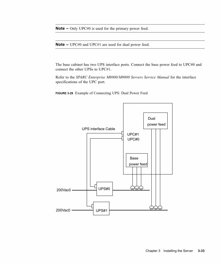
1. Attach the cable holder that comes with the product to the second notches from the bottom in the base cabinet and expansion cabinet.For the installation position, see (1) in FIGURE 3-34.
Note – The data cables for two XB units are to be secured with one cable holder.
Chapter 3 Installing the Server 3-39
FIGURE 3-34 Connecting Cables Between XB Units: Base Cabinet
16
2 4
3-40 SPARC Enterprise M8000/M9000 Servers Installation Guide • October 2012

FIGURE 3-35 Connecting Cables Between XB Units: Expansion Cabinet
2. Connect XBU#0 and XBU#8 with the DT#0, DT#1, and DT#2 cables in this order. Use a flathead screwdriver to secure the data cable connectors.
Note – Refer to the Note located before Step 1 when you connect the cable.
3. Using hook and loop fasteners, secure the DT#0, DT#1, and DT#2 cables to the cable holder on the side of the base cabinet. For the position to fix, see (2) in FIGURE 3-34.
Note – For XBU#0, giving consideration to facilitating CLKU maintenance, raise the cable a little before securing it in position.
4. Connect XBU#0 and XBU#8 with the DT#3, DT#4, and DT#5 cables in this order. Use a flathead screwdriver to secure the data cable connectors.
Note – Refer to the Note located before Step 1 when you connect the cable.
71
5 3
Chapter 3 Installing the Server 3-41

5. Using hook and loop fasteners, secure the DT#3, DT#4, and DT#5 cables to the cable holder on the side of the expansion cabinet. For the position to fix, see (3) in FIGURE 3-35.
Note – For XBU#8, giving consideration to facilitating CLKU maintenance, raise the cable a little before securing it in position.
6. Using hook and loop fasteners, secure the six connected data cables to the cable holder along the side of the base cabinet. For the locations of the securing fasteners, see (4) in FIGURE 3-34.
Note – Secure the cables for XBU#0 while lifting them up slightly, in consideration of CLKU maintenance.
7. Using hook and loop fasteners, secure the six connected data cables to the cable holder along the side of the expansion cabinet. For the locations of the securing fasteners, see (5) in FIGURE 3-35.
Note – For XBU#8, giving consideration to facilitating CLKU maintenance, raise the cable a little before securing it in position.
8. Connect XBU#0 and XBU#8 with the clock cable. Use a torque screwdriver to secure the clock cable connector with the torque of 0.2 N·m; 2.0 kgf·cm, and lay the clock cables on the data cables.
Note – If you are unable to obtain a torque screwdriver, finger tighten the clock cable connectors. Do not secure them with a regular screwdriver.
Note – Do not secure the clock cables to the cable folder along with the data cables.
Note – Refer to the Note located before Step 1 when you connect the cable.
9. Connect XBU#1 and XBU#9 with the DT#0, DT#1, and DT#2 cables in this order. Use a flathead screwdriver to secure the data cable connectors.
Note – Refer to the Note located before Step 1 when you connect the cable.
3-42 SPARC Enterprise M8000/M9000 Servers Installation Guide • October 2012

10. Using hook and loop fasteners, secure the DT#0, DT#1, and DT#2 cables to the cable holder along the side of the base cabinet. For the secured fastener location, see (6) of FIGURE 3-34.
11. Connect XBU#1 and XBU#9 with the DT#3, DT#4, and DT#5 cables in this order. Use a flathead screwdriver to secure the data cable connectors.
Note – Refer to the Note located before Step 1 when you connect the cable.
12. Using a hook and loop fastener, secure the DT#3, DT#4, and DT#5 cables to the cable holder along the side of the expansion cabinet.For the secured fastener location, see (7) in FIGURE 3-35.
13. Connect XBU#1 and XBU#9 with the clock cable. Use a torque screwdriver to secure the clock cable connector with the torque of 0.2 N·m; 2.0 kgf·cm, and lay the clock cables on the data cables.
Note – If you are unable to obtain a torque screwdriver, finger tighten the clock cable connectors. Do not secure them with a regular screwdriver.
Note – Do not secure the clock cables to the cable folder along with the data cables.
Note – Refer to the Note located before Step 1 when you connect the cable.
14. Set the data cables and the clock cables on the brackets between the base cabinet and the expansion cabinet.
Chapter 3 Installing the Server 3-43

FIGURE 3-36 View After Completing Step 8 to Step 14
15. Attach the next cable holder above the current cable holder, leaving one notch open between them.
16. Repeat Step 2 to Step 14 to connect the cables between XBU#2 and XBU#10, and secure the cable with the cable holder (see FIGURE 3-37).
3-44 SPARC Enterprise M8000/M9000 Servers Installation Guide • October 2012

FIGURE 3-37 Close-Up View of the Cable Connections
Note – If the front cover of the expansion cabinet has been removed, attach it at this point.
Chapter 3 Installing the Server 3-45

3.4.4 Connecting the Administration ConsoleThe serial port of the eXtended System Control Facility (XSCF) unit is an RJ-45 interface port, which is used to monitor the boot process and make default settings. This port is monitored and configured with the administration console connected to the serial port by an RS232C cable (serial cable), which is a server accessory.
If the administration console is any of the following, it can be used as an XSCF Shell console.■ ASCII terminal■ Workstation■ Terminal server (or patch panel connected to the terminal server)■ Personal computer
The connection of the administration console is described below.
1. Use the administration console software to verify that the following settings have been made.
2. Prepare a serial cable.The serial cable is a server accessory.
3. Connect the console to the XSCFU#0 serial port.
Note – The XSCF unit serial port is a port used for setting up the server and displaying the status of the system through the XSCF Shell.
TABLE 3-6 Settings of Terminal Software
Setting item Value
1 Baud rate 9600
2 Data length 8 bits
3 Parity None None
4 Stop bit 1 bit
5 Flow control None
6 Delay Not 0
3-46 SPARC Enterprise M8000/M9000 Servers Installation Guide • October 2012

FIGURE 3-38 Serial Port on the XSCF Unit of the M8000 Server
Chapter 3 Installing the Server 3-47

FIGURE 3-39 Serial Port on the XSCF Unit of the M9000 Server
3.5 Checking the Input PowerThis section explains how to check the input power.
3-48 SPARC Enterprise M8000/M9000 Servers Installation Guide • October 2012
3.5.1 Single-Phase Power
Caution – Equipment damage – Each outlet must be in a circuit ranging from 200 to 240 VAC (30 A) and only be used for a power cord. An outlet to which a power cord is connected must be grounded.
1. Before connecting a power cord, confirm that the main line switch on the ACS of the server is switched off.
2. Using a multimeter, verify that the input power fulfills power requirements.For details, see Section 2.2.2.2, “Power Supply Requirements” on page 2-6.
3. Connect the plug of each power cord to a dedicated outlet.
3.5.2 Three-Phase PowerUsing a multimeter, verify that the input power fulfills power requirements.
For details, see Section 2.2.2.2, “Power Supply Requirements” on page 2-6.
3.6 Setting and Checking the Required Information for the Servers Before powering on the server, perform the initial setting of XSCF.
This section explains how to specify and check the required server information.
Note – To operate the XSCF Shell, use the console that was connected following the steps indicated in Section 3.4.4, “Connecting the Administration Console” on page 3-46.
■ Section 3.6.1, “Switch On the Main Line Switches” on page 3-50■ Section 3.6.2, “Logging Into the XSCF Shell” on page 3-51■ Section 3.6.3, “Initializing the XSCF” on page 3-52■ Section 3.6.4, “Checking for a Capacity on Demand (COD) Board” on page 3-53
Chapter 3 Installing the Server 3-49

3.6.1 Switch On the Main Line SwitchesThe main line switch is the input power switch for the server. This section explains how to switch on the main line switches.
1. Set the mode switch on the operator panel to Service.
Note – The mode switching key on the operator panel is a server accessory.
FIGURE 3-40 Operator Panel
2. Switch on all the main line switches in the AC section on the equipment.
Note – Please wait at least 30 seconds before turning on the system power that you turned off, by using the main line switch or the circuit breakers on the distribution board.
a. If the M9000 server has an expansion cabinet, turn on all the main line switches located on the expansion cabinet and the power cabinet connected to the expansion cabinet first.
b. Turn on all the main line switches located on the base cabinet and the power cabinet connected to the base cabinet.
Note – The CHECK LED (3) on the XSCF unit lights momentarily immediately after turning on the main line switch. The READY LED (green) (2) on the XSCF unit blinks when initialization starts, and it stays on when initialization is completed.
Locked Service
3-50 SPARC Enterprise M8000/M9000 Servers Installation Guide • October 2012

FIGURE 3-41 XSCF Unit LEDs
3. Confirm that the ACTIVE LED (1) and READY LED (2) on the XSCFU#0 are lit.
3.6.2 Logging Into the XSCF ShellTo make the initial setting of the XSCF, first use the default user account of the XSCF. Before an appropriate user account for the user environment is registered, log in by using the default user account and password. The default user privileges are useradm and platadm.
Log into the XSCF Shell by following the procedure below.
1. When the Login window is displayed, enter the default login name.
2. When the message to prompt for key switch operation is displayed, perform the following operations in accordance with the messages.
a. Change the key switch to “Locked” position.
b. Maintain the key switch in the “Locked” position for 5 seconds.
c. Set the key switch back to “Service” position.
login: default
Change the panel mode switch to Locked and press return...
Leave it in that position for at least 5 seconds.
Change the panel mode switch to Service and press return...
1 2 3
Chapter 3 Installing the Server 3-51

Note – In the case that Step c is not performed within 1 minute, the login certification will expire.
3. Confirm that the XSCF Shell prompt is displayed.
3.6.3 Initializing the XSCFBefore each XSCF function is used, configurations and checks must be performed. This section explains the settings and checks concerning the items listed below. For detailed procedures for these settings and checks, see "Setup For Using XSCF" section in the SPARC Enterprise M3000/M4000/M5000/M8000/M9000 Servers XSCF User’s Guide and the SPARC Enterprise M3000/M4000/M5000/M8000/M9000 Servers XSCF Reference Manual.■ Registration of user accounts, passwords, and user privileges (adduser, password, and
setprivileges) (Note 1)■ Time setting (setdate, settimezone)■ SSH/telnet setting (setssh, settelnet)■ Confirmation of the XSCF host public key (showssh)■ Network interface, routing, and DNS-related settings (setnetwork, setroute,
setnameserver, and so on) (Note 2, Note 3)■ Domain to Service Processor Communications Protocol (DSCP) configuration
(setdscp) (Note 3)■ Altitude setting (setaltitude) (Note 4)■ CD-RW/DVD-RW drive unit/Tape drive unit setting (cfgdevice)
Note – (1) In preparation for maintenance work, also prepare a user account for a field engineer (FE).
Note – (2) To apply the settings, the XSCF unit must be reset with the applynetwork and rebootxscf commands.
Note – (3) The same procedures are used to make network interface (XSCF-LAN, Domain to Service Processor Communications Protocol (DSCP), and so on), routing, and DNS-related settings after logging into the XSCFU#1 through a serial connection.
XSCF>
3-52 SPARC Enterprise M8000/M9000 Servers Installation Guide • October 2012

Note – (4) To apply the specified configuration, execute the rebootxscf command and reset XSCF.
3.6.4 Checking for a Capacity on Demand (COD) BoardIf there is a COD board installed, run a diagnostic test on it.
Note – When a COD board is installed, you can not use the CPU before you install the COD hardware activation key (COD key).
For COD settings and command information, see the SPARC Enterprise M4000/M5000/M8000/M9000 Servers Capacity on Demand (COD) User’s Guide and the SPARC Enterprise M3000/M4000/M5000/M8000/M9000 Servers XSCF Reference Manual.
1. Check for a COD label on all CMUs mounted in the server.A COD label is affixed on the front of a CMU that uses a COD board.
2. Enter the showboards -va command in the XSCF Shell to check for a COD board.
3. If there is a COD board, enter the testsb command in the XSCF Shell to test the COD board.
4. Enter the showboards command in the XSCF Shell to check the test results.
3.7 Powering On/Off the SystemThis section explains the following processes.■ Section 3.7.1, “Powering On the System” on page 3-54■ Section 3.7.2, “Confirming XSCF Redundancy” on page 3-55■ Section 3.7.3, “Connecting an Ethernet Port” on page 3-57■ Section 3.7.4, “Verifying the Configuration” on page 3-58■ Section 3.7.5, “Checking the Dual-Power Feed” on page 3-59■ Section 3.7.6, “Powering Off the System” on page 3-59
Chapter 3 Installing the Server 3-53

3.7.1 Powering On the SystemTo power on the system, follow the procedure below using the operator panel.
Note – For details about each command, see the SPARC Enterprise M3000/M4000/M5000/M8000/M9000 Servers XSCF Reference Manual
1. Type the console -d 0 command at the XSCF Shell.This command switches the prompt from the XSCF console (XSCF>) to the domain console (#, the OS console).
2. Confirm that the mode switch on the operator panel is set to Service.
3. Confirm that the XSCF STANDBY LED (green) on the operator panel is lit.
FIGURE 3-42 LEDs on the Operator Panel
4. Press the POWER switch on the operator panel.The server starts and the POST diagnostics begin.
5. Confirm that ok is displayed on the domain console (OS console).
6. Check the Power LED on each unit.When the system has normally powered on, the power LED will be on.If the above description differs from the actual LED indication, see Section B.1, “Actions to Take for Common Problems” on page B-1.
7. Press the Enter, “#” (default escape character) , and “.” (period) keys.These key combinations switch you from the domain console to the XSCF console.
XSCF> console -d domain_ID (In this example, replace domain_ID with 0)#
XSCF STANDBY LED
3-54 SPARC Enterprise M8000/M9000 Servers Installation Guide • October 2012

8. Type the fmdump or showlogs commands at the XSCF Shell.
9. Confirm that no error is displayed on the XSCF console as a result of the execution of either the fmdump or the showlogs command.When an error is displayed, see Section B.2, “Using Troubleshooting Commands” on page B-2.
3.7.2 Confirming XSCF RedundancyThere are two XSCF units in the M8000/M9000 servers, and normally one of them is active and the other is on standby. The server is shipped from the factory with XSCFU#0 set as active.
Follow the instructions in this section to confirm that the active and standby XSCF units can be switched.
1. Confirm that the ACTIVE LED on XSCFU#0 is on and the ACTIVE LED on XSCFU#1 is off.
2. Enter the switchscf command in the XSCF Shell to switch XSCFU#0 from active to standby.
Note – Entering the switchscf command reboots the XSCF being switched from active to standby.
3. Confirm that "XSCF Initial Complete" is displayed after the completion of rebooting of XSCFU#0.
4. Confirm that the ACTIVE LED on XSCFU#0 is off and the ACTIVE LED on XSCFU#1 is on.
5. Change the connection of the administration console to the serial port of XSCFU#1.
6. Log into the XSCF Shell from the administration console via the serial port.
7. Enter the version command in the XSCF Shell to confirm that XSCF#0 is on standby and XSCF#1 is active.
XSCF> switchscf -t Standby The XSCF unit switch between the Active and Standby states. Continue? [y|n] :y
Chapter 3 Installing the Server 3-55

8. Enter the switchscf command in the XSCF Shell to switch XSCFU#1 from active back to standby.
9. Confirm that "XSCF Initial Complete" is displayed after the completion of rebooting of XSCFU#1.
10. Confirm that the ACTIVE LED on XSCFU#0 is on and the ACTIVE LED on XSCFU#1 is off.
11. Change the connection of the administration console to the serial port of XSCFU#0.
12. Log into the XSCF Shell from the administration console via the serial port.
13. Enter the version command in the XSCF Shell to confirm that XSCF#0 is on standby and XSCF#1 is active.
XSCF> version -c xcp<Display example: XCP1060>XSCF#0 (Standby)XCP0 (Reserve):1060XCP1 (Current):1060XSCF#1 (Active)XCP0 (Reserve):1060XCP1 (Current):1060
XSCF> switchscf -t ActiveThe XSCF unit switch between the Active and Standby states. Continue? [y|n] :y
XSCF> version -c xcp<Display example: XCP1060>XSCF#0 (Active)XCP0 (Reserve):1060XCP1 (Current):1060XSCF#1 (Standby)XCP0 (Reserve):1060XCP1 (Current):1060
3-56 SPARC Enterprise M8000/M9000 Servers Installation Guide • October 2012

3.7.3 Connecting an Ethernet PortThe system control network enables you to connect the administration console to the XSCF unit. A direct connection can be established for this purpose. However, this type of connection is usually made through a hub or switch that is unique to the system control network.
Note – The XSCF Ethernet port is IEEE 802.3i and IEEE 802.3u compliant. This requires auto-negotiation for the port into which it terminates.
For information on network connection patterns, see Section 4.1, “Network Connection Outline” on page 4-1.
1. Use an Ethernet cable to connect Ethernet port 0 on the XSCF unit (XSCF-LAN) to the hub or the LAN port of the administration console.
For connection examples for the administration console, see FIGURE 4-1 and FIGURE 4-2.
FIGURE 3-43 Ethernet Port 0 of the XSCF Unit
2. From a telnet or a secure shell (SSH) client, specify the IP address and host name of the XSCF, and the port number if necessary, and establish a connection to the XSCF Shell via the XSCF-LAN.
Note – The default port number for telnet is 23, and the default port number for SSH is 22.
3. Log into the XSCF Shell at the administration console via the serial port.
For information on the logging-in procedure, see Section 3.6.3, “Initializing the XSCF” on page 3-52.
Note – During login using SSH, you are prompted to confirm the authenticity of the fingerprint of the host public key. The reply is yes because no spoofing is assumed in this one-to-one connection.
Port 0
Chapter 3 Installing the Server 3-57

4. Confirm that the XSCF Shell prompt (XSCF>) is displayed.
3.7.4 Verifying the ConfigurationVerify the hardware configuration by following the procedure below on the administration console.
Note – For details of each command, see the SPARC Enterprise M3000/M4000/M5000/M8000/M9000 Servers XSCF Reference Manual.
1. Type the showhardconf command at the XSCF Shell.All the components mounted in the OPL system and their status information is displayed. For details on the showhardconf command and its output, see Section B.2.1, “Using the showhardconf Command” on page B-3.
2. Confirm for each unit name that an asterisk (*) is not displayed on the left of the unit name.
3. Confirm that XSCFU#0 is Active, XSCFU#1 is Standby.
4. See the list of pre-mounted components and check the information.
5. Type the showhardconf -u command at the XSCF Shell.The number of installed FRUs is displayed. For details on the showhardconf command and its output, see Section B.2.1, “Using the showhardconf Command” on page B-3.
6. Check that the configuration displayed is equivalent to the shipping list.
7. Type the console -d 0 command from the XSCF Shell.This command switches the prompt from the XSCF console (XSCF>) to the domain console (the OS console) and the ok prompt is displayed.
8. Type the probe-scsi-all command at the ok prompt.
9. Verify that the installed CD-RW/DVD-RW drive unit, tape drive unit, and hard disk units are recognized.
10. Type the show-devs command at the ok prompt.
11. Confirm that the installed PCI card has been recognized.
12. Press the Enter, “#” (default escape character) , and “.” (period) keys.The #. key sequence switches the prompt from the domain console to the XSCF console.
3-58 SPARC Enterprise M8000/M9000 Servers Installation Guide • October 2012

3.7.5 Checking the Dual-Power FeedIf the dual-power feed option is used, follow the procedure below to confirm that the system can operate even if one power feed is stopped.
1. Confirm that the system is powered on by checking the output of the showdomainstatus -a command from the XSCF Shell..
2. Confirm that all main line switches of the single power feed are switched off.■ If you installed a M8000 server, switch off main line switches ACS_A#0 to ACS_A#2.■ If you installed a M9000 server, switch off all the main line switches of the server.
3. Confirm that the POWER LED on the operator panel is lit.
4. From the XSCF Shell, verify Power failure with the showlogs event command.
5. Switch on all the main line switches that were switched off in Step 2.
6. From the XSCF Shell, confirm a power recovery by executing the showlogs event command.
7. Confirm that the LED on each PSU stops blinking and remains lit.
8. From the XSCF Shell, confirm a Power Status is On by executing the showhardconf command.
9. Confirm that all main line switches of the dual-power feed system are switched off. ■ If you installed a M8000 server, switch off the circuit breakers of the rack-mountable
dual-power feed (ACS_A#20 to ACS_A#22). ■ If you installed a M9000 server, switch off all ACSs of the power cabinet.
10. Confirm that the POWER LED on the operator panel is lit.
11. From the XSCF Shell, verify Power failure with the showlogs event command.
12. Switch on all the main line switches that were switched off in Step 9.
13. From the XSCF Shell, verify power recovery with the showlogs event command.
3.7.6 Powering Off the SystemTo power off the system, follow the procedure below on the administration console.
1. Type the poweroff -d 0 command at the XSCF Shell.
XSCF> poweroff -d domain_ID (In this example, replace domain_ID with 0)
Chapter 3 Installing the Server 3-59

2. Check the POWER LED on the operator panel.
When the POWER LED is off and XSCF STANDBY LED is on, the system has been normally powered off.
If the above description differs from the actual LED indication, see Section B.1, “Actions to Take for Common Problems” on page B-1.
3.8 Connecting Additional Peripheral DevicesTo add an External I/O Expansion Unit, a storage product, or any other peripheral devices, see the installation manual for the device.
For details on how to add PCI cards, see the SPARC Enterprise M8000/M9000 Servers Service Manual.
3-60 SPARC Enterprise M8000/M9000 Servers Installation Guide • October 2012

CHAPTER 4
Connecting Your Domains to the Network and Running the Oracle VTS Software
This chapter explains the following items which shows continuum of flow from a network connection for domain to a confirmation of hardware operation capabilities in Oracle VTS.■ Section 4.1, “Network Connection Outline” on page 4-1■ Section 4.2, “Connecting the System to Each Network” on page 4-4■ Section 4.3, “Verifying a Network Connection” on page 4-6■ Section 4.4, “Starting the Oracle Solaris Operating System” on page 4-6■ Section 4.5, “Verifying the Operation Using the Oracle VTS Software” on page 4-8
4.1 Network Connection OutlineThis section provides an overview of the domain network connections.
A server can be connected to a network through the LAN port of an IOU onboard device card_A (IOUA) that is mounted in an I/O unit. Moreover, a user-prepared LAN card can be installed in the I/O unit, and the system can use this LAN card to connect to the network. The user network displayed in FIGURE 4-1 and FIGURE 4-2 shows how you can access the domain.
4-1

FIGURE 4-1 Network Connections
User network
Switch
Server
IOU#0
IOUA LAN
IOU#1
XSCFU#0
Ethernet #1
Ethernet #0
Ethernet #1
Ethernet #0
XSCFU#1
System control network
Fire wall
Services
Administration console
remote
Switch
4-2 SPARC Enterprise M8000/M9000 Servers Installation Guide • October 2012

FIGURE 4-2 Network Connections
User network
Switch
Server
IOU#0
IOUA LAN
IOU#1
XSCFU#0
Ethernet #1
Ethernet #0
Ethernet #1
Ethernet #0
XSCFU#1
System control network
Fire wall
Administration console
Switch
IOUA LAN
IOUA LAN
IOUA LAN
Switch
Switch
Chapter 4 Connecting Your Domains to the Network and Running the Oracle VTS Software 4-3

4.2 Connecting the System to Each NetworkThis section describes how the SPARC Enterprise M8000/M9000 servers from Oracle and Fujitsu connect to each network.
To connect the server to the network, prepare one or more of the hubs, switches, and LAN cables required.
1. Connect one end of the Ethernet cable to the I/O unit.The Ethernet cable can be connected to either the LAN port of the IOUA or the LAN port of a LAN card installed in the I/O unit.
2. Connect the other end of the Ethernet cable to the customer network.
Note – By connecting the LAN port on the I/O unit to the customer network, the network can be accessed from the domain. Skip this step if the domain is to be isolated from the network.
4-4 SPARC Enterprise M8000/M9000 Servers Installation Guide • October 2012

FIGURE 4-3 IOUA LAN Port (Example)
LAN port 0
LAN port 1
Chapter 4 Connecting Your Domains to the Network and Running the Oracle VTS Software 4-5

4.3 Verifying a Network ConnectionThis section explains how to confirm the connection of the user network in Section 4.2, “Connecting the System to Each Network” on page 4-4.
1. Set the mode switch on the operator panel to Service.
2. Press the POWER switch on the operator panel to power on the system.
3. Confirm that the LINK SPEED LED on the LAN port, which has been connected to the I/O unit in Section 4.2, “Connecting the System to Each Network” on page 4-4 remains on.
■ When it is on in amber, the communication speed of LAN port is 1 G bps.■ When it is on in green, the communication speed of LAN port is 100 M bps.■ When it is off, the communication speed of LAN port is 10 M bps.
FIGURE 4-4 LINK SPEED LED on the LAN Port
4.4 Starting the Oracle Solaris Operating SystemUse this procedure to start the Oracle Solaris operating system.
To start this procedure immediately after the procedure described in Section 4.3, “Verifying a Network Connection” on page 4-6, begin with Step 3.
4-6 SPARC Enterprise M8000/M9000 Servers Installation Guide • October 2012

Note – Oracle Solaris OS is pre-installed on the slot 0 of the hard disk drive (HDD) installed on I/O unit in slot 0. When you start Oracle Solaris OS from this HDD, a message appears to configure the Oracle Solaris OS in line with the environment in use.
1. Set the mode switch on the operator panel to Service.
2. Press the POWER switch on the operator panel to power on the system.
3. Log into the XSCF Shell from the administration console.
4. Type the console -d 0 command from the XSCF Shell.This command switches the prompt from the XSCF console (XSCF>) to the domain console (#, the OS console).
5. Type the boot command at the ok prompt of the domain console (OS console).
6. During the boot process, pay attention to whether any error message is displayed on the domain console (OS console).If an error message is displayed, see Section B.1, “Actions to Take for Common Problems” on page B-1
7. At the login prompt, log in by using the root privilege.
XSCF> console -d domain_ID (In this example, replace domain_ID with 0)#
ok boot
Chapter 4 Connecting Your Domains to the Network and Running the Oracle VTS Software 4-7

4.5 Verifying the Operation Using the Oracle VTS SoftwareThe Oracle VTS diagnostic software can be used to verify the hardware operation and to check the device connection status.
This section explains how to verify operation by using Oracle VTS.
Note – Oracle VTS is installed in the Oracle Solaris OS pre-installed version. For details, see the Oracle VTS user’s guide.
This section explains how to run the Oracle VTS 7.0ps9 software from the TTY user interface.
1. Type the sunvts command to start the Oracle VTS software.
2. The Oracle VTS TTY main window appears.
# cd /usr/sunvts/bin# ./startsunvts -t
4-8 SPARC Enterprise M8000/M9000 Servers Installation Guide • October 2012

FIGURE 4-5 The Oracle VTS TTY Main Window
No. Window Item
1 Control panel
2 Test_Groups panel
3 Status panel
1
2
3
Chapter 4 Connecting Your Domains to the Network and Running the Oracle VTS Software 4-9

3. Select an item to be tested.
a. Use the tab key to move to the Test_Groups panel.
b. Use the arrow keys to select the item.
4. Run the test program.
a. Use the tab key to move to the Control panel.
b. Use the arrow keys to highlight start, and press the Return key.A diagnosis begins.
c. Confirm that no Error is displayed in the Status panel or Message panel.
5. Stop the test program.
a. Use the tab key to move to the Control panel.
b. Use the arrow keys to highlight stop, and press the Return key.
TABLE 4-1 Description of the TTY Keyboard
Key Description of Operation
Tab key Shifts the focus to another window. For example, when you press the tab key on the Control panel, the focus (highlighted part) is shifted to the Status panel, which is then framed by asterisks (*).
Arrow keys Moves between options in the panel.
Return Displays the menu.This selects and applies an option or command on the menu.
Spacebar Checks or unchecks the check box of an option in the test panel.[*]: Selected[ ]: Not selected
Backspace key Deletes text in a text field.
Escape Discards a pop-up menu or window.
Control-F Scrolls forward in a scrollable window.
Control-B Scrolls backward in a scrollable window.
Control-X Quits the TTY user interface but leaves the Oracle VTS kernel running.
Control-L Refreshes the TTY window.
4-10 SPARC Enterprise M8000/M9000 Servers Installation Guide • October 2012

6. Check the test results.When the test program is stopped, the number of test loops executed and the number of errors are displayed.Confirm that there is no error.
7. Press the Enter key, and then press the "#" and "." ( period) keys.This key combination switches you from the domain console to the XSCF console.
8. Type the fmdump command or the showlogs error command at the XSCF Shell.
9. Confirm that no errors are displayed in the XSCF console after using the fmdump or the showlogs error commands.If an error is displayed, see Section B.2, “Using Troubleshooting Commands” on page B-2.
10. Type the poweroff -d 0 command at the XSCF Shell to power off the system.
11. Set the mode switch on the operator panel back to Locked, and hand the key to the system administrator.
12. Close the door of the cabinet and hand the door key to the system administrator.
XSCF> poweroff -d 0 (In this example, the domain ID is 0)
Chapter 4 Connecting Your Domains to the Network and Running the Oracle VTS Software 4-11

4-12 SPARC Enterprise M8000/M9000 Servers Installation Guide • October 2012

APPENDIX A
System Views
This appendix provides views of each model. ■ Section A.1, “M8000 Server Views” on page A-2■ Section A.2, “M9000 Server Views” on page A-4■ Section A.3, “Power Cabinet Views” on page A-6■ Section A.4, “Operator Panel Overview” on page A-10
A-1

A.1 M8000 Server ViewsFIGURE A-1 M8000 Server - Front View
TABLE A-1 M8000 Server Unit Names
No. Name Abbreviation
1 Power supply unit PSU#0 to #8
2 DC-DC converter DDC_A#0
3 DC-DC converter DDC_A#1
4 eXtended System Control Facility unit XSCFU_B#0
5 eXtended System Control Facility unit XSCFU_B#1
6 Tape drive unit TAPEU*
7 CD-RW/DVD-RW drive unit DVDU
8 2 FAN unit FAN_B#0,#1
A-2 SPARC Enterprise M8000/M9000 Servers Installation Guide • October 2012

FIGURE A-2 M8000 Server - Rear View
9 3 FAN unit FAN_A#0 to #3
10 CPU memory board unit CMU#0 to #3
11 Power supply unit (for DPF) PSU#40 to #48
* Contact your sales representative for tape drive unit options on M8000/M9000 servers.
TABLE A-2 M8000 Server Unit Names
No. Name Abbreviation
1 2 FAN unit FAN_B#2 to #7
2 I/O unit IOU#0 to #3
3 AC section ACS_A#0
4 AC section (for DPF) ACS_C#0
TABLE A-1 M8000 Server Unit Names (Continued)
No. Name Abbreviation
1
34
2
Appendix A System Views A-3

A.2 M9000 Server ViewsFIGURE A-3 M9000 Server - Front View
TABLE A-3 M9000 Server Unit Names
No. Name Abbreviation
1 2 FAN unit FAN_A#0 to #3, #20 to #23
2 AC section ACS_B#0, ACS_B#1
3 Power supply unit PSU#0 to #14, #20 to #34
4 Crossbar unit (for base cabinet) XBU_B#0 to #7, #8 to #15
5 Clock control unit (M8000, M9000 for base cabinet)
CLKU_B#0
6 Clock control unit (M8000, M9000 for base cabinet)
CLKU_B#1
7 eXtended System Control Facility unit (M8000, M9000 for base cabinet)
XSCFU_B#0
1
3
2
4
11
151312
14
1
2
3
4
11
99
1010
5
87
6
A-4 SPARC Enterprise M8000/M9000 Servers Installation Guide • October 2012

FIGURE A-4 M9000 Server - Rear View
8 eXtended System Control Facility unit(M8000, M9000 for base cabinet)
XSCFU_B#1
9 Tape drive unit TAPEU*
10 CD-RW/DVD-RW drive unit DVDU
11 I/O unit IOU#0, #2, #4, #6, #8, #10, #12, #14
12 eXtended System Control Facility unit(For M9000 Expansion cabinet)
XSCFU_C#0
13 eXtended System Control Facility unit(For M9000 Expansion cabinet)
XSCFU_C#1
14 Clock control unit (For M9000 Expansion cabinet)
CLKU_B#2
15 Clock control unit (For M9000 Expansion cabinet)
CLKU_B#3
* Contact your sales representative for tape drive unit options on M8000/M9000 servers.
TABLE A-3 M9000 Server Unit Names (Continued)
No. Name Abbreviation
1
2
3
1
2
3
Appendix A System Views A-5

A.3 Power Cabinet Views
A.3.1 M8000 Server + Power Cabinet
FIGURE A-5 M8000 Server + Power Cabinet - Front View
TABLE A-4 M9000 Server Unit Names
No. Name Abbreviation
1 2 FAN unit FAN_A#4 to #15, #24 to #35
2 CPU memory board unit CMU#0 to #7, #8 to #15
3 I/O unit IOU#9, #11, #13, #15, #1, #3, #5, #7
1
A-6 SPARC Enterprise M8000/M9000 Servers Installation Guide • October 2012

FIGURE A-6 M8000 Server + Power Cabinet - Rear View
TABLE A-5 M8000 Server + Power Cabinet Unit Names
No. Name Abbreviation
1 Power supply unit PSU#40 to #48
TABLE A-6 M8000 Server + Power Cabinet Unit Name
No. Name Abbreviation
1 AC section ACSTPH#0, ACSTPH#1
1
Appendix A System Views A-7

A.3.2 M9000 Server + Power Cabinet
FIGURE A-7 M9000 Server + Power Cabinet - Front View
TABLE A-7 M9000 Server + Power Cabinet Unit Names
No. Name Abbreviation
1 Power supply unit PSU#40 to #54, #60 to #74
2 AC section ACS_B#2, ACS_B#3(for single-phase)
1
2
1
2(*)(*)
* For single-phaseBase side power cabinet Expansion side power cabinet
A-8 SPARC Enterprise M8000/M9000 Servers Installation Guide • October 2012

FIGURE A-8 M9000 Server + Power Cabinet - Rear View
TABLE A-8 M9000 Server + Power Cabinet Unit Name
No. Name Abbreviation
1 AC section ACSTPH#0, ACSTPH#1(for three-phase)
11
(*)(*)
* For three-phase
Expansion side power cabinet Base side power cabinet
Appendix A System Views A-9

A.4 Operator Panel OverviewYou can use the operator panel to view the operating status of the server as a whole and perform operations such as system power operations. You can use it while the cabinet doors are closed.
The following figure shows the appearance of the operator panel.
FIGURE A-9 Operator Panel
TABLE A-9 LEDs and Switches on the Operator Panel
No. Icon Name Description
1 POWER LED (Green)
Indicates the server power status.• On: Server has power.• Off: Server is without power.• Blinking: The power-off sequence is in progress.
2 XSCF STANDBY LED (Green)
Indicates the readiness of the XSCF.• On: XSCF unit is functioning normally.• Off: XSCF unit is stopped.• Blinking: Under system initialization after NFB on, or
under system power-on process.
3 CHECK LED (Amber)
Indicates that server detected a fault. • On: Error detected that disables the startup.• Off: Normal, or the breaker is off (power failure).• Blinking: Indicates the position of fault.
1 2 3 4 5
6
A-10 SPARC Enterprise M8000/M9000 Servers Installation Guide • October 2012

4 POWER switch Switch to direct server power on/power off.
5 Mode switch The Locked setting:Normal operation mode• The system can be powered on with the POWER switch,
but it cannot be powered off with the POWER switch.• The key can be pulled out at this key position.
The Service setting:Mode for maintenance• The system can be powered on and off with the POWER
switch.• The key cannot be pulled out at this key position.• Maintenance is performed in Service mode while the
server is stopped.
TABLE A-10 Function of the Mode Switch
FunctionState Definition
Mode SwitchLocked Service
Inhibition of Break Signal Reception Enabled. Reception of the break signal can be enabled or disabled for each domain using setdomainmode.
Disabled
Power On/Off by power switch Only power on is enabled Enabled
TABLE A-9 LEDs and Switches on the Operator Panel (Continued)
No. Icon Name Description
Appendix A System Views A-11

A-12 SPARC Enterprise M8000/M9000 Servers Installation Guide • October 2012

APPENDIX B
Troubleshooting
This appendix explains how to deal with possible problems during system installation.■ Section B.1, “Actions to Take for Common Problems” on page B-1■ Section B.2, “Using Troubleshooting Commands” on page B-2■ Section B.3, “Traditional Oracle Solaris Troubleshooting Commands” on page B-11
B.1 Actions to Take for Common ProblemsThis section describes the more common problems in installation and solutions to the problems.
Caution – Please do not make any repairs to the system by yourself. Contact us and ensure that repair of the system will be performed by a certified service engineer. When the authorized service personnel perform their work on your system, they may need to log into the system with the domainadm privilege for the administration of a specific domain, the
TABLE B-11 Types of Troubleshooting Methods
Problem Solution
The system cannot be powered on.
• Confirm that the power cords are connected.• Confirm that the ACS for the input power supply is on.• If a UPS is connected, confirm that the server and the UPS are correctly
connected, the UPS is powered on, and the LED on the UPS indicates the normal state.
• Confirm that the distribution panel for the device is on.
B-1

platadm privilege for management of the entire system, or the fieldeng privilege for the maintenance work. If our engineer asks you to supply this permission, please take appropriate action to ensure that the engineer can perform the required work.
In the event that problems occur, the methods of troubleshooting may vary depending on the server operating status and the nature of the problem. The following table outlines different types of troubleshooting methods.
B.2 Using Troubleshooting CommandsThe following commands are detailed in this section.■ Section B.2.1, “Using the showhardconf Command” on page B-3■ Section B.2.2, “Using the showlogs Command” on page B-8■ Section B.2.3, “Using the showstatus Command” on page B-8■ Section B.2.4, “Using the fmdump Command” on page B-9■ Section B.2.5, “Using the fmadm faulty Command” on page B-10■ Section B.2.6, “Using the fmstat Command” on page B-11
TABLE B-12 Types of Troubleshooting Methods
Troubleshooting Method Explanation
Checking LEDs The system LEDs on the operation panel indicate the system or hardware error that has been detected during an initial diagnosis or system operation. Also, the LEDs on a FRU, such as an XSCFU, PSU, or fan, identify a faulty device or indicate the device status.For details on types of LEDs and error indications of LEDs, see the SPARC Enterprise M8000/M9000 Servers Service Manual.
Checking from the XSCF Shell Detailed error status and the history of device conditions can be checked from the XSCF Shell.For details, see the XSCF User’s Guide for your server.
Checking the system log file The system log file (/var/adm/messages) can be checked to find a message for the error or panic detected by the OS.For details, see the SPARC Enterprise M8000/M9000 Servers Service Manual.
B-2 SPARC Enterprise M8000/M9000 Servers Installation Guide • October 2012

B.2.1 Using the showhardconf CommandThe showhardconf command displays information about each FRU, including the following information:■ Current configuration and status■ Number of installed FRUs■ Domain information■ External I/O Expansion Unit information■ Name properties of PCI cards
CODE EXAMPLE B-1 displays example showhardconf command output, and. CODE EXAMPLE B-2 displays example showhardconf -u command output.
CODE EXAMPLE B-1 Example showhardconf Command Output
XSCF> showhardconfSPARC Enterprise M9000; + Serial:PA30601004; Operator_Panel_Switch:Locked; + Power_Supply_System:Single-1Phase; Ex:Single-1Phase; SCF-ID:XSCF#0; + System_Power:On; System_Phase:Cabinet Power On; Domain#0 Domain_Status:Running;
CMU#0 Status:Normal; Ver:8301h; Serial:PP0616B579 ; + FRU-Part-Number:CA06620-D004 B0 /371-4930-02 ; + Memory_Size:128 GB; + Type:C; CPUM#0-CHIP#0 Status:Normal; Ver:0a01h; Serial:PP091505ZY ; + FRU-Part-Number:CA06620-D061 B1 /371-4929-02 ; + Freq:3.000 GHz; Type:48; + Core:4; Strand:2; CPUM#1-CHIP#0 Status:Normal; Ver:0a01h; Serial:PP091505ZW ; + FRU-Part-Number:CA06620-D061 B1 /371-4929-02 ; + Freq:2.280 GHz; Type:16; + Core:2; Strand:2; CPUM#2-CHIP#0 Status:Normal; Ver:0a01h; Serial:PP0915060H ; + FRU-Part-Number:CA06620-D061 B1 /371-4929-02 ; + Freq:3.000 GHz; Type:48; + Core:4; Strand:2; CPUM#3-CHIP#0 Status:Normal; Ver:0a01h; Serial:PP09150603 ; + FRU-Part-Number:CA06620-D061 B1 /371-4929-02 ; + Freq:3.000 GHz; Type:48; + Core:4; Strand:2; MEM#00A Status:Normal; + Code:7f7ffe00000000004aEBE41RE4ABHA-5C-E 3020-22211d88; + Type:4B; Size:4 GB; MEM#00B Status:Normal;
Appendix B Troubleshooting B-3

+ Code:7f7ffe00000000004aEBE41RE4ABHA-5C-E 3020-2a002a55; + Type:4B; Size:4 GB; : MEM#33A Status:Normal; + Code:ce0000000000000001M3 93T5168AZ0-CD5 3041-741a8ea1; + Type:4B; Size:4 GB; MEM#33B Status:Normal; + Code:ce0000000000000001M3 93T5168AZ0-CD5 3041-741a8ea1; + Type:4B; Size:4 GB; : CMU#2 Status:Normal; Ver:8301h; Serial:PP0618K472 ; + FRU-Part-Number:CA06620-D004 B0 /371-4930-02 ; + Memory_Size:32 GB; + Type:C; CPUM#0-CHIP#0 Status:Normal; Ver:0a01h; Serial:PP0608J517 + FRU-Part-Number:CA06620-D061 B1 /371-4929-02 ; + Freq:3.000 GHz; Type:48; + Core:4; Strand:2; CPUM#1-CHIP#0 Status:Normal; Ver:0a01h; Serial:PP0620P552 ; + FRU-Part-Number:CA06620-D061 B1 /371-4929-02 ; + Freq:3.000 GHz; Type:48; + Core:4; Strand:2; CPUM#2-CHIP#0 Status:Normal; Ver:0a01h; Serial:PP0631Q396 ; + FRU-Part-Number:CA06620-D061 B1 /371-4929-02 ; + Freq:3.000 GHz; Type:48; + Core:4; Strand:2; CPUM#3-CHIP#0 Status:Normal; Ver:0a01h; Serial:PP0629H443 ; + FRU-Part-Number:CA06620-D061 B1 /371-4929-02 ; + Freq:3.000 GHz; Type:48; + Core:4; Strand:2; MEM#00A Status:Normal; + Code:7f7ffe00000000004aEBE10RD4AGFA-5C-E 3020-221d6855; + Type:1A; Size:1 GB; MEM#00B Status:Normal; + Code:7f7ffe00000000004aEBE10RD4AGFA-5C-E 3020-221fcdb7; + Type:1A; Size:1 GB; : MEM#33A Status:Normal; + Code:7f7ffe00000000004aEBE10RD4AGFA-5C-E 3020-221d678b; + Type:1A; Size:1 GB; MEM#33B Status:Normal; + Code:2cffffffffffffff0818HTF12872Y-53EB3 0300-69aedd7a; + Type:1A; Size:1 GB; CMU#3 Status:Normal; Ver:8301h; Serial:PP0638F192 ; + FRU-Part-Number:CA06620-D004 A0 /371-4930-01 ; + Memory_Size:64 GB; + Type:C;
CODE EXAMPLE B-1 Example showhardconf Command Output (Continued)
B-4 SPARC Enterprise M8000/M9000 Servers Installation Guide • October 2012

CPUM#0-CHIP#0 Status:Normal; Ver:0901h; Serial:PP0631P606 ; + FRU-Part-Number:CA06620-D061 B1 /371-4929-02 ; + Freq:3.000 GHz; Type:48; + Core:4; Strand:2; CPUM#1-CHIP#0 Status:Normal; Ver:0901h; Serial:PP0630M355 ; + FRU-Part-Number:CA06620-D061 B1 /371-4929-02 ; + Freq:3.000 GHz; Type:48; + Core:4; Strand:2; CPUM#2-CHIP#0 Status:Normal; Ver:0901h; Serial:PP0628D036 ; + FRU-Part-Number:CA06620-D061 B1 /371-4929-02 ; + Freq:3.000 GHz; Type:48; + Core:4; Strand:2; CPUM#3-CHIP#0 Status:Normal; Ver:0901h; Serial:PP0630M365 ; + FRU-Part-Number:CA06620-D061 B1 /371-4929-02 ; + Freq:3.000 GHz; Type:48; + Core:4; Strand:2; MEM#00A Status:Normal; + Code:7f7ffe00000000004aEBE10RD4AGFA-5C-E 3020-221d6855; + Type:1A; Size:1 GB; MEM#00B Status:Normal; + Code:7f7ffe00000000004aEBE10RD4AGFA-5C-E 3020-221fcdb7; + Type:1A; Size:1 GB; : MEM#33A Status:Normal; + Code:7f7ffe00000000004aEBE10RD4AGFA-5C-E 3020-221d678b; + Type:1A; Size:1 GB; MEM#33B Status:Normal; + Code:2cffffffffffffff0818HTF12872Y-53EB3 0300-69aedd7a; + Type:1A; Size:1 GB; : IOU#0 Status:Normal; Ver:0101h; Serial:PP072102UN ; ; + FRU-Part-Number:CA06620-D102 B1 /371-2217-02 ; + Type:A; PCI#0 Name_Property:pci; Card_Type:IOUA; + Serial:PP0611T826 ; Type:2; + FRU-Part-Number: CA21138-B84X 010AE/371-5000-05 ; PCI#1 Status:Normal; Name_Property:LSILogic,sas; Card_Type:Other; + Serial:0000004; Type:F20 + FRU-Part-Number:5111500-01 IOU#1 Status:Normal; Ver:0101h; Serial:PP072102UM ; + FRU-Part-Number:CA06620-D102 B1 /371-2217-02 ; + Type:A; PCI#0 Name_Property:pci; Card_Type:IOUA; + Serial:PP0611T825 ; Type:2; + FRU-Part-Number: CA21138-B84X 010AE/371-5000-05 IOU#2 IOU#2 Status:Normal; Ver:4201h; Serial:PP0727053S; + FRU-Part-Number:CA06620-D103 A0 /371-4931-01 ;
CODE EXAMPLE B-1 Example showhardconf Command Output (Continued)
Appendix B Troubleshooting B-5

Refer to the showhardconf(8) man page for more information.
+ Type:B; PCI#4 Name_Property:pci; Card_Type:IOUA; + Serial:PP0611T823 ; Type:2; + FRU-Part-Number: CA21138-B84X 010AE/371-5000-05 ; : XSCFU_B#0 Status:Normal,Active; Ver:0201h; Serial:PP080600DW ; + FRU-Part-Number:CA06620-D342 C0 /371-2228-02 ; : XBU_B#0 Status:Normal; Ver:0201h; Serial:PP0641X324 ; + FRU-Part-Number:CA06620-D302 C1 /371-2240-03 ; : CLKU_B#0 Status:Normal; Ver:0201h; Serial:PP0542M679 ; + FRU-Part-Number:CA06620-D322 C1 /371-2230-03 ; : OPNL#0 Status:Normal; Ver:0101h; Serial:PP06058246 ; + FRU-Part-Number:CA06620-D382 A2 /371-2239-01 ; PSU#0 Status:Normal; Serial:FA11155187; + FRU-Part-Number:CA01022-0690 20H /371-2219-08 ; + Power_Status:On; : FANBP_A#0 Status:Normal; Ver:0101h; Serial:PP0607D266 ; + FRU-Part-Number:CA21128-B71X 011AE/371-2222-05 ; FAN_A#0 Status:Normal; Serial:PA0605B287; + FRU-Part-Number:CA06622-D012 A5 /371-2237-01 ; : FAN_A#15 Status:Normal; Serial:PA0605B303; + FRU-Part-Number:CA06622-D012 A5 /371-2237-01 ; : FANBP_B#0 Status:Normal; Ver:0201h; Serial:PP0607D270 ; + FRU-Part-Number:CA21128-B72X 011AE/371-2223-05 ; FAN_A#4 Status:Normal; Serial:PA0605B297; + FRU-Part-Number:CA06622-D012 A5 /371-2237-01 ; : FAN_A#9 Status:Normal; Serial:PA0605B300; + FRU-Part-Number:CA06622-D012 A5 /371-2237-01 ; : SWBP#0 Status:Normal; Ver:0101h; Serial:PP0607E759 ; + FRU-Part-Number:CA20397-B57X 022AG/371-2243-01 ; MEDBP#0 Status:Normal; Ver:0101h; Serial:PP06058497 ; + FRU-Part-Number:CA20397-B56X 005AA/371-2244-01 ;
CODE EXAMPLE B-1 Example showhardconf Command Output (Continued)
B-6 SPARC Enterprise M8000/M9000 Servers Installation Guide • October 2012

CODE EXAMPLE B-2 Example showhardconf -u Command Output
XSCF> showhardconf -uSPARC Enterprise M9000; Memory_Size:240 GB; +---------------------------------------+------------+ | FRU | Quantity | +---------------------------------------+------------+ | CMU | 4 | | Type:C; | ( 4) | | CPUM | 16 | | Freq:3.000 GHz; | ( 16) | | MEM | 112 | | Type:1A; Size:1 GB; | ( 48) | | Type:2B; Size:2 GB; | ( 32) | | Type:4B; Size:4 GB; | ( 32) | | IOU | 8 | | Type:A; | ( 6) | | Type:B; | ( 2) | | XSCFU_B | 2 | | XBU_B | 8 | | CLKU_B | 2 | | OPNL | 1 | | PSU | 15 | | FANBP_A | 1 | | FANBP_B | 1 | | FAN_A | 16 | | SWBP | 1 | | MEDBP | 1 | +---------------------------------------+------------+
Appendix B Troubleshooting B-7

B.2.2 Using the showlogs CommandThe showlogs command will display the contents of a specified log file in the order of the timestamp, starting with the oldest date. The showlogs command can display the following logs:■ Error log■ Power log■ Event log■ Temperature and humidity record■ Monitoring message log■ Console message log■ Panic message log■ IPL message log
B.2.3 Using the showstatus CommandDisplays the information concerning the units failed or degraded and the units on the next upper layer, among the FRUs composing the system. An asterisk (*) indicating abnormal unit is displayed along with any of the following the "Status:":■ Normal■ Faulted■ Degraded ■ Deconfigured■ Maintenance
XSCF> showlogs errorDate: Mar 30 12:45:31 JST 2005 Code: 00112233-44556677-8899aabbcceeff0Status: Warning Occurred: Mar 30 17:45:31.000 JST 2005FRU: PSU#1,PSU#2Msg: ACFAIL occurred (ACS=3)(FEP type = A1)Date: Mar 30 17:45:31 JST 2005 Code: 00112233-44556677-8899aabbcceeff00Status: Alarm Occurred: Mar 30 17:45:31.000 JST 2005FRU: PSU#1,PSU#2,*Msg: ACFAIL occurred (ACS=3)(FEP type = A1)XSCF>0
B-8 SPARC Enterprise M8000/M9000 Servers Installation Guide • October 2012

In this example, a CPU module and memory module in a CPU memory unit are degraded.
B.2.4 Using the fmdump CommandThe fmdump command can be used to display the contents of any log files associated with the Oracle Solaris fault manager.
This example assumes there is only one fault.
B.2.4.1 Using the fmdump -V CommandYou can obtain more details by using the -V option with the fmdump command.
At least three lines of new output are delivered to the user with the -V option.■ The first line is a summary of information you have seen before in the console message
but includes the timestamp, the UUID, and the Message-ID.■ The second line is a declaration of the certainty of the diagnosis. In this case we are 100%
sure the failure is in the ASIC described. If the diagnosis involves multiple components you might see two lines here with 50% in each (for example)
■ The FRU line declares the part which needs to be replaced in order to return the server to a fully operational state.
■ The rsrc line describes what component was taken out of service as a result of this fault.
XSCF> showstatus CMU#0;* CPUM#0-CHIP#0 Status:Faulted;* MEM#00A Status:Faulted;XSCF>
# fmdump TIME UUID SUNW-MSG-IDNov 02 10:04:15.4911 0ee65618-2218-4997-c0dc-b5c410ed8ec2 SUN4-8000-0Y
# fmdump -V -u 0ee65618-2218-4997-c0dc-b5c410ed8ec2TIME UUID SUNW-MSG-IDNov 02 10:04:15.4911 0ee65618-2218-4997-c0dc-b5c410ed8ec2 SUN4-8000-0Y100% fault.io.fire.asicFRU: hc://product-id=SUNW,A70/motherboard=0rsrc: hc:///motherboard=0/hostbridge=0/pciexrc=0
Appendix B Troubleshooting B-9

B.2.4.2 Using the fmdump -e CommandTo get information about the errors that caused this failure, use the -e option with the fmdump command.
B.2.5 Using the fmadm faulty CommandThe fmadm faulty command can be used by administrators and service personnel to view and modify system configuration parameters that are maintained by the Oracle Solaris Fault Manager. The fmadm faulty command is primarily used to determine the status of a component involved in a fault.
The PCI device is degraded and is associated with the same UUID as seen above. You might also see “faulted” states.
B.2.5.1 Using the fmadm config CommandThe fmadm config command output shows you the version numbers of the diagnosis engines in use by your server, as well as their current state. You can check these versions against information on the My Oracle Support website to determine if you are running the latest diagnostic engines.
# fmdump -eTIME CLASSNov 02 10:04:14.3008 ereport.io.fire.jbc.mb_per
# fmadm faultySTATE RESOURCE / UUID----------------------------------------------------------------degraded dev:////pci@1e,600000 0ee65618-2218-4997-c0dc-b5c410ed8ec2
# fmadm config MODULE VERSION STATUS DESCRIPTIONcpumem-diagnosis 1.5 active UltraSPARC-III/IV CPU/Memory Diagnosiscpumem-retire 1.0 active CPU/Memory Retire Agenteft 1.13 active eft diagnosis enginefmd-self-diagnosis 1.0 active Fault Manager Self-Diagnosisio-retire 1.0 active I/O Retire Agentsyslog-msgs 1.0 active Syslog Messaging Agent
B-10 SPARC Enterprise M8000/M9000 Servers Installation Guide • October 2012

B.2.6 Using the fmstat CommandThe fmstat command can report statistics associated with the Oracle Solaris fault manager. The fmstat command shows information about DE performance. In the example below, the eft DE (also seen in the console output) has received an event which it accepted. A case is “opened” for that event and a diagnosis is performed to “solve” the cause for the failure.
B.3 Traditional Oracle Solaris Troubleshooting CommandsThese superuser commands can help you determine if you have issues in your workstation, in the network, or within another server that you are networking with.
The following commands are described in this section:■ Section B.3.1, “iostat Command” on page B-11■ Section B.3.2, “prtdiag Command” on page B-13■ Section B.3.3, “prtconf Command” on page B-15■ Section B.3.4, “netstat Command” on page B-16■ Section B.3.5, “ping Command” on page B-17■ Section B.3.6, “ps Command” on page B-18■ Section B.3.7, “prstat Command” on page B-19
Most of these commands are located in the /usr/bin or /usr/sbin directories.
B.3.1 iostat CommandThe iostat command iteratively reports terminal, drive, and tape I/O activity, as well as CPU utilization.
# fmstatmodule ev_recv ev_acpt wait svc_t %w %b open solve memsz bufszcpumem-diagnosis 0 0 0.0 0.0 0 0 0 0 3.0 K0cpumem-retire 0 0 0.0 0.0 0 0 0 0 0 0eft 1 1 0.0 1191.8 0 0 1 1 3.3M 11Kfmd-self-diagnosis 0 0 0.0 0.0 0 0 0 0 0 0io-retire 1 0 0.0 32.4 0 0 0 0 37b 0syslog-msgs 1 0 0.0 0.5 0 0 0 0 32b 0
Appendix B Troubleshooting B-11

B.3.1.1 iostat Command OptionsTABLE B-13 describes options for the iostat command and how those options can help troubleshoot the server.
The following example shows output for one iostat command.
TABLE B-13 Options for iostat
Option Description How It Can Help
No option Reports status of local I/O devices. A quick three-line output of device status.
-c Reports the percentage of time the system has spent in user mode, in system mode, waiting for I/O, and idling.
Quick report of CPU status.
-e Displays device error summary statistics. The total errors, hard errors, soft errors, and transport errors are displayed.
Provides a short table with accumulated errors. Identifies suspect I/O devices.
-E Displays all device error statistics. Provides information about devices: manufacturer, model number, serial number, size, and errors.
-n Displays names in descriptive format. Descriptive format helps identify devices.
-x For each drive, reports extended drive statistics. The output is in tabular form.
Similar to the -e option, but provides rate information. This helps identify poor performance of internal devices and other I/O devices across the network.
# iostat -Enc0t0d0 Soft Errors: 0 Hard Errors: 0 Transport Errors: 0Model: ST3120026A Revision: 8.01 Serial No: 3JT4H4C2Size: 120.03GB <120031641600 bytes>Media Error: 0 Device Not Ready: 0 No Device: 0 Recoverable: 0Illegal Request: 0c0t2d0 Soft Errors: 0 Hard Errors: 0 Transport Errors: 0Vendor: LITE-ON Product: COMBO SOHC-4832K Revision: O3K1 Serial No: Size: 0.00GB <0 bytes>Media Error: 0 Device Not Ready: 0 No Device: 0 Recoverable: 0Illegal Request: 0 Predictive Failure Analysis: 0
B-12 SPARC Enterprise M8000/M9000 Servers Installation Guide • October 2012

B.3.2 prtdiag CommandThe prtdiag command displays configuration and diagnostic information. The diagnostic information identifies any failed component.
The prtdiag command is located in the /usr/platform/platform-name/sbin/ directory.
Note – The prtdiag command might indicate a slot number different than that identified elsewhere in this document. This is normal.
B.3.2.1 prtdiag Command OptionsTABLE B-14 describes options for the prtdiag command and how those options can help troubleshooting.
TABLE B-14 Options for prtdiag
Option Description How It Can Help
No option Lists components. Identifies CPU timing and PCI cards installed.
-v Verbose mode. Displays the time of the most recent AC power failure and the most recent hardware fatal error information.
Provides the same information as no option. Additionally lists fan status, temperatures, ASIC, and PROM revisions.
Appendix B Troubleshooting B-13

The following example shows output for the prtdiag command in verbose mode.
# prtdiagSystem Configuration: Sun Microsystems sun4u XXXX SPARC EnterpriseM8000 ServerSystem clock frequency: 960 MHzMemory size: 8192 Megabytes
================================= CPUs ================================ CPU CPU Run L2$ CPU CPULSB Chip ID MHz MB Impl. Mask--- ---- ------------------------------------- ---- --- ---- ---- 00 0 0, 1, 2, 3, 4, 5, 6, 7 3000 12.0 7 192 01 1 40, 41, 42, 43, 44, 45, 46, 47 3000 12.0 7 192 02 2 80, 81, 82, 83, 84, 85, 86, 87 3000 12.0 7 192============================ Memory Configuration =====================
Memory Available Memory DIMM # of Mirror InterleaveLSB Group Size Status Size DIMMs Mode Factor--- ------ ------------ ------- ------ ----- ------- ---------- 01 A 4096MB okay 1024MB 4 no 2-way 02 A 4096MB okay 1024MB 4 no 2-way
========================= IO Cards =========================
LSB Name Model---- ------ ------------------------- 00 scsi LSI,1064 00 network N/A 00 network N/A
==================== Hardware Revisions ====================System PROM revisions:----------------------OBP 4.24.13 2010/02/08 13:17
=================== Environmental Status ===================Mode switch is in UNLOCK mode
=================== System Processor Mode ===================SPARC64-VII mode
B-14 SPARC Enterprise M8000/M9000 Servers Installation Guide • October 2012

B.3.3 prtconf CommandSimilar to the show-devs command run at the ok prompt, the prtconf command displays the devices that are configured.
The prtconf command identifies hardware that is recognized by the Oracle Solaris OS. If hardware is not suspected of being bad yet software applications are having trouble with the hardware, the prtconf command can indicate if the Oracle Solaris software recognizes the hardware, and if a driver for the hardware is loaded.
B.3.3.1 prtconf Command OptionsTABLE B-15 describes options for the prtconf command and how those options can help troubleshooting.
The following example shows output for the prtconf command.
TABLE B-15 Options for prtconf
Option Description How It Can Help
No option Displays the device tree of devices recognized by the OS.
If a hardware device is recognized, then it is probably functioning properly. If the message “(driver not attached)” is displayed for the device or for a sub-device, then the driver for the device is corrupt or missing.
-D Similar to the output of no option, however the device driver is listed.
Lists the driver needed or used by the OS to enable the device.
-p Similar to the output of no option, yet is abbreviated. Reports a brief list of the devices.
-V Displays the version and date of the OpenBoot PROM firmware.
Provides a quick check of firmware version.
Appendix B Troubleshooting B-15

B.3.4 netstat CommandThe netstat command displays the network status.
B.3.4.1 netstat Command OptionsTABLE B-16 describes options for the netstat command and how those options can help troubleshooting.
# prtconfSystem Configuration: Sun Microsystems sun4uMemory size: 8192 MegabytesSystem Peripherals (Software Nodes):
SUNW,SPARC-Enterprise scsi_vhci, instance #0 packages (driver not attached) SUNW,builtin-drivers (driver not attached) SUNW,builtin-drivers (driver not attached) deblocker (driver not attached) disk-label (driver not attached) terminal-emulator (driver not attached) obp-tftp (driver not attached) zfs-file-system (driver not attached) hsfs-file-system (driver not attached) chosen (driver not attached) openprom (driver not attached) client-services (driver not attached) options, instance #0 aliases (driver not attached) memory (driver not attached) virtual-memory (driver not attached) pseudo-console, instance #0 nvram (driver not attached) pseudo-mc, instance #0 pseudo-mc, instance #1 pseudo-mc, instance #4
cmp (driver not attached) core (driver not attached) cpu (driver not attached) cpu (driver not attached)(The rest is omitted.)
B-16 SPARC Enterprise M8000/M9000 Servers Installation Guide • October 2012

The following example shows output for the netstat -p command.
B.3.5 ping CommandThe ping command sends ICMP ECHO_REQUEST packets to network hosts. Depending on how the ping command is configured, the output displayed can identify troublesome network links or nodes. The destination host is specified in the variable hostname.
TABLE B-16 Options for netstat
Option Description How It Can Help
-i Displays the interface state, including packets in/out, error in/out, collisions, and queue.
Provides a quick overview of the network status.
-i interval Providing a trailing number with the -i option repeats the netstat command every interval seconds.
Identifies intermittent or long duration network events. By piping netstat output to a file, overnight activity can be viewed all at once.
-p Displays the media table. Provides MAC address for hosts on the subnet.
-r Displays the routing table. Provides routing information.
-n Replaces host names with IP addresses. Used when an address is more useful than a host name.
# netstat -pNet to Media Table: IPv4Device IP Address Mask Flags Phys Addr ------ -------------------- --------------- ----- ---------------bge0 phatair-46 255.255.255.255 08:00:20:92:4a:47bge0 ns-umpk27-02-46 255.255.255.255 08:00:20:93:fb:99bge0 moreair-46 255.255.255.255 08:00:20:8a:e5:03bge0 fermpk28a-46 255.255.255.255 00:00:0c:07:ac:2ebge0 fermpk28as-46 255.255.255.255 00:50:e2:61:d8:00bge0 kayakr 255.255.255.255 08:00:20:d1:83:c7bge0 matlock 255.255.255.255 SP 00:03:ba:27:01:48bge0 toronto2 255.255.255.255 08:00:20:b6:15:b5bge0 tocknett 255.255.255.255 08:00:20:7c:f5:94bge0 mpk28-lobby 255.255.255.255 08:00:20:a6:d5:c8bge0 efyinisedeg 255.255.255.255 08:00:20:8d:6a:80bge0 froggy 255.255.255.255 08:00:20:73:70:44bge0 d-mpk28-46-245 255.255.255.255 00:10:60:24:0e:00bge0 224.0.0.0 240.0.0.0 SM 01:00:5e:00:00:00
Appendix B Troubleshooting B-17

B.3.5.1 ping Command OptionsTABLE B-17 describes options for the ping command and how those options can help troubleshooting.
The following example shows output for the ping -s command.
B.3.6 ps CommandThe ps command lists the status of processes. Using options and rearranging the command output can assist in determining the resource allocation.
TABLE B-17 Options for ping
Option Description How It Can Help
hostname The probe packet is sent to hostname and returned. Verifies that a host is active on the network.
-g hostname Forces the probe packet to route through a specified gateway.
By identifying different routes to the target host, those individual routes can be tested for quality.
-i interface Designates which interface to send and receive the probe packet through.
Enables a simple check of secondary network interfaces.
-n Replaces host names with IP addresses. Used when an address is more beneficial than a host name.
-s Pings continuously in one-second intervals. Ctrl-C aborts. Upon abort, statistics are displayed.
Helps identify intermittent or long-duration network events. By piping ping output to a file, activity overnight can later be viewed at once.
-svR Displays the route the probe packet followed in one second intervals.
Indicates probe packet route and number of hops. Comparing multiple routes can identify bottlenecks.
# ping -s teddybearPING teddybear: 56 data bytes64 bytes from teddybear (192.146.77.140): icmp_seq=0. time=1. ms64 bytes from teddybear (192.146.77.140): icmp_seq=1. time=0. ms64 bytes from teddybear (192.146.77.140): icmp_seq=2. time=0. ms^C----teddybear PING Statistics----3 packets transmitted, 3 packets received, 0% packet lossround-trip (ms) min/avg/max = 0/0/1
B-18 SPARC Enterprise M8000/M9000 Servers Installation Guide • October 2012

B.3.6.1 ps Command OptionsTABLE B-18 describes options for the ps command and how those options can help troubleshooting.
The following example shows output for one ps command.
Note – When using sort with the -r option, the column headings are printed so that the value in the first column is equal to zero.
B.3.7 prstat CommandThe prstat utility iteratively examines all active processes and reports statistics based on the selected output mode and sort order. The prstat command provides output similar to the ps command.
TABLE B-18 Options for ps
Option Description How It Can Help
-e Displays information for every process. Identifies the process ID and the executable.
-f Generates a full listing. Provides the following process information: user ID, parent process ID, time when executed, and the path to the executable.
-o option Enables configurable output. The pid, pcpu, pmem, and comm options display process ID, percent CPU consumption, percent memory consumption, and the responsible executable, respectively.
Provides only most important information. Knowing the percentage of resource consumption helps identify processes that are affecting performance and might be hung.
# ps -eo pcpu,pid,comm|sort -rn1.4 100317 /usr/openwin/bin/Xsun0.9 100460 dtwm0.1 100677 ps0.1 100600 ksh0.1 100591 /usr/dt/bin/dtterm0.1 100462 /usr/dt/bin/sdtperfmeter0.1 100333 mibiisa%CPU PID COMMAND0.0 100652 /bin/csh. . .
Appendix B Troubleshooting B-19

B.3.7.1 prstat Command OptionsTABLE B-19 describes options for the prstat command and how those options can help troubleshooting.
The following example shows output for the prstat command.
TABLE B-19 Options for prstat
Option Description How It Can Help
No option Displays a sorted list of the top processes that are consuming the most CPU resources. List is limited to the height of the terminal window and the total number of processes. Output is automatically updated every five seconds. Ctrl-C aborts.
Output identifies process ID, user ID, memory used, state, CPU consumption, and command name.
-n number Limits output to number of lines. Limits amount of data displayed and identifies primary resource consumers.
-s key Permits sorting list by key parameter. Useful keys are cpu (default), time, and size.
-v Verbose mode. Displays additional parameters.
# prstat -n 5 -s sizePID USERNAME SIZE RSS STATE PRI NICE TIME CPU PROCESS/NLWP 100524 mm39236 28M 21M sleep 48 0 0:00.26 0.3% maker6X.exe/1100317 root 28M 69M sleep 59 0 0:00.26 0.7% Xsun/1100460 mm39236 11M 8760K sleep 59 0 0:00.03 0.0% dtwm/8100453 mm39236 8664K 4928K sleep 48 0 0:00.00 0.0% dtsession/4100591 mm39236 7616K 5448K sleep 49 0 0:00.02 0.1% dtterm/1Total: 65 processes, 159 lwps, load averages: 0.03, 0.02, 0.04
B-20 SPARC Enterprise M8000/M9000 Servers Installation Guide • October 2012