Embed Size (px)
Citation preview

© University of Dundee
SpaceNet - SpaceWire-RT
Initial Protocol Definition
Revision: Draft A Issue 1.1
Date: 12th May 2008
ESA Contract Number 220774-07-NL/LvH
Ref: SpW-RT WP3-200.1
Space Technology Centre
School of Computing
University of Dundee
Dundee, DD1 4HN
Scotland, UK
spacetech.computing.dundee.ac.uk

SpaceNet – SpaceWire-RT
Protocol Definition
2 © University of Dundee
Document Authors
Steve Parkes
Document Change Log
Date Revision No Comments
12th May 2008 Draft A Issue 1.1 Update following comments from ESA
25th March 2008 Draft A Issue 1.0 First issue
A comprehensive list of the changes made to this document in each major revision is provided in
section 2.

SpaceNet – RMAP IP
Protocol Definition
© University of Dundee 3
CONTENTS
CONTENTS ................................................................................................................................................. 3
I LIST OF FIGURES................................................................................................................................ 6
II LIST OF TABLES ................................................................................................................................. 7
1 INTRODUCTION ................................................................................................................................... 8
1.1 BACKGROUND ............................................................................................................................ 8
1.2 AIMS AND OBJECTIVES ................................................................................................................ 8
1.3 GUIDE TO DOCUMENT ................................................................................................................. 8
1.4 ACRONYMS AND ABBREVIATIONS ................................................................................................. 9
1.5 REFERENCE DOCUMENTS ......................................................................................................... 10
1.6 APPLICABLE DOCUMENTS ......................................................................................................... 10
2 TERMS AND DEFINITIONS .................................................................................................................. 12
2.1 DEFINITIONS FROM THE OPEN SYSTEMS INTERCONNECTION (OSI) BASIC REFERENCE MODEL .... 12
2.2 TERMS DEFINED IN THIS RECOMMENDATION .............................................................................. 12
3 PROTOCOL OVERVIEW ..................................................................................................................... 14
3.1 COMMUNICATIONS MODEL ........................................................................................................ 14
3.2 QUALITY OF SERVICE ................................................................................................................ 14
3.3 CHANNELS ............................................................................................................................... 15
3.4 SHARED RESOURCES ............................................................................................................... 16
3.5 ARCHITECTURE ........................................................................................................................ 22
3.5.1 User Application Interface .............................................................................................. 23
3.5.2 Segmentation Function .................................................................................................. 24
3.5.3 End to End Flow Control ................................................................................................ 24
3.5.4 Retry Function ................................................................................................................ 28
3.5.5 Error detection ................................................................................................................ 33
3.5.6 Redundancy Function .................................................................................................... 33
3.5.7 Address Translation ....................................................................................................... 34
3.5.8 Encapsulation ................................................................................................................. 36
3.5.9 Source Channel Arbitration ............................................................................................ 38
3.5.10 Priority ............................................................................................................................ 38

SpaceNet – SpaceWire-RT
Protocol Definition
4 © University of Dundee
3.5.11 Scheduling ...................................................................................................................... 39
4 USER APPLICATION INTERFACE ........................................................................................................ 42
4.1 SOURCE USER INTERFACE ........................................................................................................ 42
4.2 DESTINATION USER INTERFACE ................................................................................................. 42
5 SEGMENTATION ............................................................................................................................... 43
6 END TO END FLOW CONTROL ........................................................................................................... 44
7 RETRY ............................................................................................................................................. 46
7.1 TYPES OF ERROR: .................................................................................................................... 46
7.2 CRC GENERATION AND CHECKING: ............................................................................................ 46
7.3 SENDING A PDU ....................................................................................................................... 46
7.4 RECEIVING A PDU .................................................................................................................... 47
7.5 RECEIVING A PDU WHEN THE DESTINATION CHANNEL BUFFER IS FULL ....................................... 47
7.6 RECEIVING A PACKET CONTAINING ERRORS .............................................................................. 48
7.7 RECEIVING AN ACKNOWLEDGEMENT: ......................................................................................... 49
7.8 ACKNOWLEDGEMENT TIME-OUT: ............................................................................................... 50
7.9 RETRY COUNT: ........................................................................................................................ 51
8 REDUNDANCY .................................................................................................................................. 52
8.1 REDUNDANCY MANAGEMENT .................................................................................................... 52
8.2 RETRY AND REDUNDANCY FOR DIFFERENT TYPES OF SERVICE .................................................. 52
8.2.1 Best Effort ....................................................................................................................... 52
8.2.2 Assured .......................................................................................................................... 53
8.2.3 Reserved ........................................................................................................................ 53
8.2.4 Guaranteed .................................................................................................................... 53
9 ADDRESS TRANSLATION .................................................................................................................. 54
10 ENCAPSULATION .............................................................................................................................. 55
10.1 PDU ........................................................................................................................................ 55
10.2 ACK ........................................................................................................................................ 56
10.3 BFCT ...................................................................................................................................... 58
10.4 BACK ...................................................................................................................................... 59
11 PRIORITY ......................................................................................................................................... 61
SpaceNet – RMAP IP
Protocol Definition
© University of Dundee 5
12 RESOURCE RESERVATION ................................................................................................................ 62
12.1 TIME-SLOTS ............................................................................................................................. 62
12.2 RESOURCES AND CHANNELS ..................................................................................................... 62
12.3 BEST EFFORT AND ASSURED TRAFFIC ....................................................................................... 62
12.4 SCHEDULED SYSTEM ................................................................................................................ 63
13 NETWORK CONFIGURATION PARAMETERS ........................................................................................ 64
14 DOCUMENT CHANGES ...................................................................................................................... 65
SpaceNet – SpaceWire-RT
Protocol Definition
6 © University of Dundee
I LIST OF FIGURES
Figure 3-1 Typical SpaceWire based data-handling architecture ............................. 17
Figure 3-2 Typical architecture with redundancy removed for clarity ....................... 17
Figure 3-3 Slot allocation in scheduled system ........................................................ 21
Figure 3-4 Flow Control Mechanism: BFCT Time-Out ............................................. 25
Figure 3-5 Flow Control Mechanism: Cancelling BFCT Time-Out Timers ................ 26
Figure 3-6 Flow Control Mechanism: Missing BACK ................................................ 27
Figure 3-7 Retry Mechanism .................................................................................... 28
Figure 3-8 Simultaneous Retry ................................................................................. 30
Figure 3-9 Time-Slot Retry ....................................................................................... 32
Figure 3-10 Example Address Translation ............................................................... 35
Figure 3-11 PDU Encapsulation ............................................................................... 36
Figure 3-12 Control Code Encapsulation ................................................................. 38
Figure 10-1 PDU Encapsulation ............................................................................... 55
Figure 10-2 ACK Encapsulation ............................................................................... 57
Figure 10-3 BFCT Encapsulation ............................................................................. 58
Figure 10-4 BACK Encapsulation ............................................................................. 59

SpaceNet – RMAP IP
Protocol Definition
© University of Dundee 7
II LIST OF TABLES
Table 1-1: Reference Documents ............................................................................ 10
Table 1-2: Applicable Documents ............................................................................ 11
Table 3-1 Utilisation of resources (links) .................................................................. 19
Table 3-2 Channel allocations .................................................................................. 20
Table 3-3 Example Channel Numbering for Priority Arbitration ................................ 39
Table 3-4 Example Schedule Table ......................................................................... 40
Table 3-5 Example Schedule Table with Priority ...................................................... 41
Table 14-1: Changes to Document (Draft to Draft) .................................................. 65

SpaceNet – SpaceWire-RT
Protocol Definition
8 © University of Dundee
1 INTRODUCTION
1.1 BACKGROUND
The requirements for SpaceWire-RT have been provided in WP2-100.1 SpaceWire-RT Requirements
[AD8]. Note that RT stands for Real-Time (or alternatively Reliable and Timely).
1.2 AIMS AND OBJECTIVES
The aim of this document is to present an initial set of protocols that meet the SpaceWire-RT
Requirements. These initial protocols will then be prototyped and then update according to the results
of the prototyping.
The various techniques that are being considered to meet the SpaceWire-RT requirements are
considered and described first. Then each function required to implement the protocols is defined in
some detail. Some details are necessarily sketchy at this stage but will mature as the prototypes are
developed and evaluated.
WARNING
This current document is an early draft of the proposed standard and if for
discussion purposes only. It will change after prototyping work has been
completed. Applicable documents may also change.
DO NOT USE THIS DOCUMENT TO DESIGN DEVICES OR SYSTEMS!
1.3 GUIDE TO DOCUMENT
Section 2 lists the terms and definitions relevant to the SpaceWire-RT set of protocols.
Section 3 provides an overview of the SpaceWire-RT protocols and various techniques that are
proposed for their implementation.
Section 4 describes the user interface specification to SpaceWire-RT at the source and destination.
Section 5 covers the specification of the segmentation function.
Section 6 presents the specification for the end to end flow control mechanism.
Section 7 gives the specification for SpaceWire-RT retry functions.
Section 8 describes the specification of the autonomous and managed redundancy mechanisms.
Section 9 presents the specification for the address resolution function.

SpaceNet – RMAP IP
Protocol Definition
© University of Dundee 9
Section 10 covers the specification of the protocol data unit (PDU) encapsulation function.
Section 11 provides the specification of the resource reservation mechanisms that support timely data
delivery.
Section 13 provides an initial look at the network configuration parameters required for SpaceWire-
RT.
1.4 ACRONYMS AND ABBREVIATIONS
AD Applicable Document
BACK BFCT Acknowledgement
BFCT Buffer Flow Control Token
CCSDS Consultative Committee for Space Data Systems
ECSS European Cooperation for Space Standardization
ESA European Space Agency
ESTEC ESA Space Technology and Research Centre
I/F Interface
PC Personal Computer
PDU Protocol Data Unit
QoS Quality of Service
RD Reference Document
RMW Read/Modify/Write
SDU Service Data Unit
SOIS Spacecraft Onboard Interface Services
SpW SpaceWire
TCONS Time-Critical Onboard Network Services
UoD University of Dundee

SpaceNet – SpaceWire-RT
Protocol Definition
10 © University of Dundee
1.5 REFERENCE DOCUMENTS
The documents referenced in this document are listed in Table 1-1.
Table 1-1: Reference Documents
REF Document Number Document Title
RD1 UoD-SpaceNet v7, 23rd
April 2007
Proposal for SpaceWire Network and Future Onboard Data-Handling, Technical, Management and Administrative Proposal
RD2 TEC-ED/WG/2005.15 SpaceWire Network “SpW-Net” SpaceWire and Future Onboard Data Handling SpaceNet Statement of Work Annex1
RD3 CCSDS 000.0-W-1.1 Time Critical Onboard Network (TCONS) and Onboard Bus LAN (OBL) Architecture April 2006
RD4 CCSDS 000.0-W-1.1 Time Critical Onboard Network (TCONS) Quality of Service September 2005
RD5 CCSDS 000.0-R-1.1 Spacecraft Onboard Interface Services Intra-Network Service April 2006
1.6 APPLICABLE DOCUMENTS
The documents applicable to this document are listed in Table 1-2.

SpaceNet – RMAP IP
Protocol Definition
© University of Dundee 11
Table 1-2: Applicable Documents
REF Document Number Document Title
AD1 ECSS-E50-12A, January 2003 SpaceWire: Links, nodes, routers and networks
AD2 ECSS-E50-11A Draft 0.5 SpaceWire Protocols Feb 2008
AD3 CCDSD ccc.c-R-1.0 Draft Red Book
Spacecraft Onboard Interface Services Memory Access Service Jan 2007
AD4 CCDSD ccc.c-R-1.0 Draft Red Book
Spacecraft Onboard Interface Services Subnetwork Packet Service Jan 2007
AD5 CCDSD ccc.c-R-1.0 Draft Red Book
Spacecraft Onboard Interface Services Test Service Jan 2007
AD6 CCDSD ccc.c-R-1.0 Draft Red Book
Spacecraft Onboard Interface Services Time Distribution Service Jan 2007
AD7 CCDSD ccc.c-R-1.0 Draft Red Book
Spacecraft Onboard Interface Services Device Discovery Service Jan 2007
AD8 SpW-RT WP3-100.1 SpaceWire-RT Requirements, February 2008

SpaceNet – SpaceWire-RT
Protocol Definition
12 © University of Dundee
2 TERMS AND DEFINITIONS
In this section the terms and definition proposed for the SpaceWire-RT standard are provided in the
form required by ECSS.
2.1 DEFINITIONS FROM THE OPEN SYSTEMS INTERCONNECTION (OSI) BASIC
REFERENCE MODEL
Layer subdivision of the architecture, constituted by subsystems of the same rank
Protocol data unit (PDU) unit of data specified in a protocol and consisting of protocol-control-
information and user data.
Service capability of a layer (service provider) together with the layers beneath it, which is provided
to service-users.
Service data unit (SDU) set of data which is semantically unchanged when transferred between peer
entities in a given layer and which is not interpreted by the supporting entities in that layer.
2.2 TERMS DEFINED IN THIS RECOMMENDATION
For the purposes of this Recommendation, the following definitions also apply. Many other terms that
pertain to specific items are defined in the appropriate sections.
ACK acknowledgement
Acknowledgement control PDU used to indicate reception of a data PDU without error and in the
correct sequence
BACK control PDU use to indicate reception of a buffer flow control token
BFCT buffer flow control token
buffer flow control token control PDU used to indicate availability of space in a destination buffer
byte 8-bits
channel identifier for network resources comprising source destination buffer, links on path through
the SpaceWire network and source buffer
CRC cyclic redundancy code
cyclic redundancy code a code used to check for errors in a packet
delimited having a known and finite length
duplicate packet a copy of a packet that has already been received once
epoch repeat cycle time for time-slot identifiers

SpaceNet – RMAP IP
Protocol Definition
© University of Dundee 13
maximum data unit The maximum size of data that a user can give to SpaceWire-RT. Note that the
MDU is required to ensure that different sources of data get fair access to the transmission medium,
by multiplexing traffic on a packet by packet basis. When a large data unit is being sent, other sources
can gain access to the transmission medium after each segment of the large data unit has been sent.
packet delimited byte aligned data unit
priority the relative urgency and precedence for sending of an data unit relative to other data units
QoS Quality of Service.
Quality of Service level of service that is requested and provided
time-slot smallest unit of time division in a SpaceWire-RT network
Service Data Unit user data provided to SpaceWire-RT for sending over the SpaceWire network
using one of the SpaceWire-RT services
SDU Service Data Unit
segmentation division of service data units by SpaceWire-RT into shorter sections (segments) that
are short enough to be sent over the SpaceWire-RT network. SpaceWire-RT is responsible for
reassembling the segments back into link service data units at the target.
sequence number incrementing number given to each unique PDU sent which is use to detect
missing and duplicate packets
service access point an interface to SpaceWire-RT that is identified by an initiator or target address
and from which a user application can access the SpaceWire-RT services
user application a software or hardware system that is using the services of SpaceWire-RT.
user data data that a user of SpaceWire-RT wishes to send across a SpaceWire network.
SpaceNet – SpaceWire-RT
Protocol Definition
14 © University of Dundee
3 PROTOCOL OVERVIEW
In this section an informative description of the SpaceWire-RT protocols is provided as an introduction
to the subsequent normative specifications.
3.1 COMMUNICATIONS MODEL
The communications model for SpaceWire-RT is one of virtual point-to-point connections across the
SpaceWire network each of which connects a source channel buffer in one node to a destination
channel buffer in another node. There are two types of system supported:
Asynchronous – where the sending of information over the SpaceWire network is asynchronous and
priority is used to provide timeliness of delivery. Information in lower number source channels will be
sent before information in higher number channels.
Synchronous – where information is sent over the SpaceWire network synchronously with each
source channel being assigned one or more time-slots when it is allowed to transmit information. One
or more source channels may be assigned to a single time-slot in which case the lower channel
numbers allocated to a time-slot have priority over higher channel numbers assigned to that time-slot.
Timeliness of delivery is controlled by a schedule table used to specify which source channel can
send information in which time-slot. This provides deterministic delivery.
A user application writes into one of the source channel buffers available. This information is then
transferred across the SpaceWire network and become available in the corresponding destination
channel buffer.
3.2 QUALITY OF SERVICE
SpaceWire-RT provides four quality of service (QoS) classes:
The Best Effort QoS provides a service which is not reliable (i.e. does not retry in the event of a
failure to deliver) and is not timely (i.e. does not deliver information within specified time constraints).
Makes a single attempt to deliver data to its destination but cannot ensure that it will be
delivered successfully.
Data is provided without errors and without duplication.
The order of data packets is not necessarily preserved (TBC).
Priority indicates the relative urgency with which PDUs should be handled by the sub-
network. Priority is applied across the best-effort and assured service classes where both
classes are provided.

SpaceNet – RMAP IP
Protocol Definition
© University of Dundee 15
The Assured QoS provides a service which is reliable (i.e. retries in the event of a failure to deliver)
but is not timely.
Ensures delivery of data to its destination.
Should it not be possible to provide the assured service this is indicated to the sending entity
Data is provided in sequence (within a priority value), complete, without errors and without
duplication.
Priority indicates the relative urgency with which PDUs should be handled by the sub-
network. Priority is applied across the best-effort and assured service classes where both
classes are provided.
The Reserved QoS provides a service which is not reliable, but is timely (i.e. when a packet is
delivered it is delivered on time).
Makes a single attempt to deliver data to its destination but cannot ensure that it will be
delivered successfully.
Data is provided in sequence (within a channel), without errors and without duplication.
A Channel defines the resources that are used to transfer the SDU across the SpaceWire
network.
The Guaranteed QoS provides a service which is both reliable and timely (i.e. it will retry in the event
of a failure to deliver and deliver information on time).
Ensures delivery of data to its destination.
Should it not be possible to provide the guaranteed service this is indicated to the sending
entity i.e. the user is informed if it is not possible to deliver the data.
Data is provided in sequence (within a channel), complete, without errors and without
duplication.
A Channel defines the resources that are used to transfer the SDU across the SpaceWire
network.
Best effort and assured services are for asynchronous systems. Resource reserved and guaranteed
services are for synchronous systems.
3.3 CHANNELS
A channel is a set of network resources that connects a source user application in a source node to a
destination user application in a destination node. It includes the following:
SpaceNet – SpaceWire-RT
Protocol Definition
16 © University of Dundee
Channel buffer in the source (source channel buffer)
SpaceWire links over which the PDUs travel
Channel buffer in the destination (destination channel buffer)
A source user application that wants to send information over a channel to a destination user
application writes data into the source channel buffer when there is space in that buffer. Data from
this buffer is taken out in chunks with each chunk being put in a separate SpaceWire packet. The
SpaceWire packets are sent across the SpaceWire network using the links specified by the channel.
When they arrive at the destination node the user information in the SpaceWire packets is extracted
and put in the destination channel buffer ready for the destination user application to read. When
there is no room in the destination channel buffer the source node it prevented from sending any
further packets to that destination channel buffer using a flow-control mechanism.
A node can have one channel going to just one destination node, many channels each going to a
different node, many channels all going to the same node, etc. Channels provide virtual point-to-point
communications across a SpaceWire network. The entry to a channel in a source node is where data
is fed in by a user application. That data will appear at the exit of the channel in the destination node.
Priority is implemented using more than one channel between a source and destination. Information
placed in the lower number channel will be transferred before information in a higher number channel.
3.4 SHARED RESOURCES
Timely delivery of information over a SpaceWire network requires control over the resources in the
network. This section considers the resources that need to be managed.
3.4.1.1 SpaceWire Links as Resources
The resources to be managed by the SpaceWire-RT resource reservation mechanism are the
SpaceWire links and the source and destination channel buffers. SpaceWire routers need not be
managed by the resource reservation mechanism as they are non-blocking switches: provided that
there are no conflicts on the SpaceWire links the routers will not block. Source and destination nodes
need not be managed by the resource reservation mechanism as they are effectively managed by
managing the SpaceWire links to the source or destination. For example, a SpaceWire node can
happily receive two packets concurrently provided that they arrive on separate SpaceWire links. It is
important that the source and destination channel buffers are managed, however.
3.4.1.2 Example Onboard Data-Handling Architecture
To help understand the resource reservation, consider the typical SpaceWire based data handling
architecture shown in Figure 3-1.

SpaceNet – RMAP IP
Protocol Definition
© University of Dundee 17
Prime
Redundant
Instrument
1
High Rate
Memory
Instrument
2
Processor
Router
Router
Memory
Processor
Instrument
3Router
Instrument
4
Sensor
A
RTCSensor
B
Sensor
C
Telemetry /
Ground Command
Prime
Telemetry /
Ground Command
Redundant
Ground Station
Figure 3-1 Typical SpaceWire based data-handling architecture
This diagram shows both prime and redundant units and SpaceWire links. For the sake of clarity
these redundant units have been removed in Figure 3-2.
Instrument
1
High Rate
Memory
Instrument
2
Processor
Router
Instrument
3Router
Instrument
4
Sensor
A
RTCSensor
B
Sensor
C
Telemetry /
Ground Command
Prime
Link A
Link B
Link C
Link D
Links E/F
Links G/HLink I
Link J
Link K
Links E/F and G/H are configured in GAR pairs Ground Station
Figure 3-2 Typical architecture with redundancy removed for clarity
As an example let’s assume the following use case parameters and features:

SpaceNet – SpaceWire-RT
Protocol Definition
18 © University of Dundee
SpaceWire links are all running at 200 Mbits/s data signalling rate and, allowing for SpaceWire
overheads and some margin, assume that the effective maximum data rate is 100 Mbits/s over
each link in both directions.
Instrument 1 is a high data rate instrument that has to send data to the memory at a rate of up to
100 Mbits/s to the memory unit.
Instruments 2 sends data at up to 25 Mbits/s to the memory unit.
Instruments 3 sends data at up to 12.5 Mbits/s to the memory unit.
Instrument 4 sends data at up to 12.5 Mbits/s to the processor for processing. The processor then
sends this data to the memory system at a similar data rate.
The RTC gathers data from several sensors, packages this data, and passes it to the memory
unit. The required data rate is relatively low.
The memory unit stores data from the instruments including the processed data from instrument
4. It sends the stored data to the down link telemetry unit for transmission to a ground station. The
data rate between the memory unit and the telemetry unit is up to 100 Mbits/s.
The processor is responsible for routine control of the instruments and for processing the data
from instrument 4. The required data rate is relatively low.
The ground command unit can relay ground commands to any of onboard units. The required
data rate is relatively low.
Table 3-1 lists how each of the SpaceWire links are used in the example data handling architecture.

SpaceNet – RMAP IP
Protocol Definition
© University of Dundee 19
Table 3-1 Utilisation of resources (links)
Link Left to right / up Right to left/ down
A Not shared Processor commands and ground commands
B Instruments 2, 3, 4 Processor commands and ground commands
C RTC Processor commands and ground commands
D Telecommands Data from memory for down link
E/F Instruments 1, 2, 3, 4 and RTC
Processor commands and ground
commands
Date from memory for down link
G/H Data from instruments or memory for
processing
Processor commands
Processed data
I Not shared Processor commands and ground commands
J Not shared Processor commands and ground commands
K Not shared Processor commands and ground commands
The highlighted table entries are those ones where potential conflict can occur because there are
several possible units that want to use the particular SpaceWire link. Note that since SpaceWire is a
full-duplex, bi-directional data link the two directions of each link are considered separately.
Now consider how the resource reservation can be used to manage the flow of data across the links
to avoid potential conflict over the use of the links. Table 3-2 shows example channel allocations for
the various types of communication that goes on in the data handling system. Note: uppercase
notation is used for links containing information flowing in one direction and lowercase used for
information flowing in the opposite direction.

SpaceNet – SpaceWire-RT
Protocol Definition
20 © University of Dundee
Table 3-2 Channel allocations
Channel
No.
Traffic Links used
L to R / Up
Links used
R to L / Down
1 Instrument 1 to memory A, E/F
2 Instrument 2 to memory I, B, E/F
3 Instrument 3 to memory J, B, E/F
4 Instrument 4 to processor for processing K, B, G/H
5 RTC sensor data to memory C, E/F
6 Processor to memory – processed data E/F g/h
7 Memory to telemetry e/f, d
8 Processor commands to any other unit E/F g/h, a, b, c, i, j, k
9 Ground commands to any other unit D, E/F, G/H a, b, c, i, j, k
Please note that channel number 8 includes communications from processor to instrument 1 (g/h, a),
processor to instrument 2 (g/h, b, i), processor to instrument 3 (g/h, b, j), processor to instrument 3
(g/h, b, k), processor to RTC (g/h, c) and processor to memory (g/h, E/F). The communication for
channel 9 is similar.
3.4.1.3 Time-Slots
Scheduling requires a means of controlling the traffic on the network. This is done by splitting using
equal divisions of time during which a discrete set of network communications can take place. These
divisions of time are known as time-slots. Time-slots are distributed in SpaceWire using SpaceWire
time-codes. There are 64 unique time-codes so a natural division is to have 64 time slots in a
schedule or bandwidth allocation cycle. The 64 time-slots are referred to as an epoch. Time slots are
used in the scheduled system for allocating network bandwidth to the network traffic.
3.4.1.4 Scheduled System
Once the channels have been defined and the resources needed by each channel determined it is a
relatively straightforward exercise (for the example) to allocate the channels to a time-slot in a
scheduled system, taking into account the required maximum data-rates that have to be supported for
each unit. An example schedule is illustrated in Figure 3-3.

SpaceNet – RMAP IP
Protocol Definition
© University of Dundee 21
Slot 0 Slot 1 Slot 2 Slot 3 Slot 4 Slot 5 Slot 6 Slot 7
A, E/F A, E/F A, E/F A, E/F A, E/F A, E/F A, E/F A, E/FChannel 1
Channel 2
Channel 3
Channel 4
Channel 5
Channel 6
Channel 7
Channel 8
Channel 9
I, B, E/F I, B, E/F
J, B, E/F
K, B, G/H
C, E/F
g/h, E/F
e/f, d e/f, d e/f, d e/f, d e/f, d e/f, d e/f, d e/f, d
E/F, g/h,
a,b,c,I,j,k
Slot 8 …
D,E/F,G/H
a,b,c,i,j,k
Slot 63
A, E/F
e/f, d
D,E/F,G/H
a,b,c,i,j,k
Figure 3-3 Slot allocation in scheduled system
The time-slots are listed along the top. In this example eight slots have been filled in which are
repeated eight times for the full 64 time-slots. The nine channels are listed along the left hand side.
The shaded boxes show when a particular channel is allowed to send data. For example Channel 2 is
permitted to send data in time-slots 0, 4, 8, 12, etc. Inside each box the resources needed for the data
transfer are listed. For example Channel 2 requires links I, B and E/F. Note that E/F means either link
E or link F since these two links are considers as a group adaptive routing (GAR) group.
In any one time-slot several communications may be happening concurrently provided that they do
not conflict i.e. two or more channels communicating in any one time-slot do not require the same
resources. When (GAR) is being used this constraint alters as the bandwidth available increases with
the number of links in a group. In our example there are two links (E and F) in the E/F group. This
means that in any one time-slot, up to two channels may be using group E/F. Since the links are full-
duplex, bi-directional data flowing in one direction does not impede data flowing in the opposite
direction. Hence lower case link resources (one direction) do not conflict with uppercase link
resources (other direction).
As may be seen from the schedule table channels 1 and 7 may send data at any time. Channel 2 has
25% of the link bandwidth (one slot every four) and channel 3 has 12.5% bandwidth (one slot every
eight).
When a particular time-slot comes around then the channels that are scheduled to send data in that
time-slot are allowed to send one or more PDUs provided that they fit within the duration of the time-
slot. Typically a time-slot will be long enough to allow at least one packet of maximum permitted
length to be sent.

SpaceNet – SpaceWire-RT
Protocol Definition
22 © University of Dundee
When retry is being used (Assured or Guaranteed service), there has to be enough room in the time-
slot to send the required number of retries (typically there would be just one retry in a scheduled
system).
3.4.1.5 Resources for Flow Control and Acknowledgements
As well as the main flow of PDUs containing data, there will be traffic in the other direction containing
acknowledgments and flow control information related to the transfer of the PDUs.
For best effort and assured QoS where there is no control over resource utilisation, acknowledgments
and flow control information can be sent without regard to possible delays over the SpaceWire
network as timely delivery is not important for these QoS classes.
For resource reserved and guaranteed QoS where the resource utilisation is managed using time-
slots, it is important that any acknowledgements are sent immediately that the packet is received and
that resource is allocated for the acknowledgements and also for any flow control information. To
provide this additional resource the time-slots are made longer than the maximum PDUs, long enough
so that there is time for an acknowledgement (and flow control information) to be sent at the end of a
time-slot. Time-slots are thus split into two parts:
PDU transfer phase
Acknowledgement phase
During the PDU transfer phase PDUs are sent according to the schedule. During the acknowledgment
phase acknowledgments are sent for the PDUs sent and received in the transfer phase, along with
any flow control information.
3.4.1.6 Best Effort and Assured Traffic over a Scheduled System
To send asynchronous traffic over a scheduled system it is necessary to assign the asynchronous
traffic to channels with defined potential resource utilisation. This is necessary to prevent resource
conflicts between asynchronous and synchronous traffic.
Several channels containing asynchronous traffic from a source to several different destinations may
be assigned to the same time-slot for transfer across the SpaceWire network provided that none of
the paths taken conflict with any other traffic on the network in the same time-slot. Only one of these
channels can send information in the allocated time-slot.
3.5 ARCHITECTURE
The SpaceWire-RT protocol includes the following functions:
User application interface
SpaceNet – RMAP IP
Protocol Definition
© University of Dundee 23
Segmentation
End to end flow control
Retry
Redundancy
Address Translation
PDU encapsulation
Priority
Resource reservation
Each of these functions is described in the following subsections.
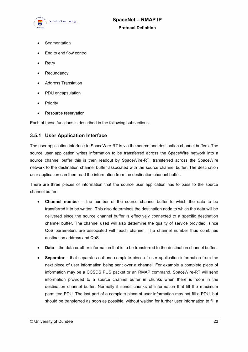
3.5.1 User Application Interface
The user application interface to SpaceWire-RT is via the source and destination channel buffers. The
source user application writes information to be transferred across the SpaceWire network into a
source channel buffer this is then readout by SpaceWire-RT, transferred across the SpaceWire
network to the destination channel buffer associated with the source channel buffer. The destination
user application can then read the information from the destination channel buffer.
There are three pieces of information that the source user application has to pass to the source
channel buffer:
Channel number – the number of the source channel buffer to which the data to be
transferred it to be written. This also determines the destination node to which the data will be
delivered since the source channel buffer is effectively connected to a specific destination
channel buffer. The channel used will also determine the quality of service provided, since
QoS parameters are associated with each channel. The channel number thus combines
destination address and QoS.
Data – the data or other information that is to be transferred to the destination channel buffer.
Separator – that separates out one complete piece of user application information from the
next piece of user information being sent over a channel. For example a complete piece of
information may be a CCSDS PUS packet or an RMAP command. SpaceWire-RT will send
information provided to a source channel buffer in chunks when there is room in the
destination channel buffer. Normally it sends chunks of information that fill the maximum
permitted PDU. The last part of a complete piece of user information may not fill a PDU, but
should be transferred as soon as possible, without waiting for further user information to fill a

SpaceNet – SpaceWire-RT
Protocol Definition
24 © University of Dundee
maximum size PDU. The separator is used to signal to SpaceWire-RT that the information in
the source channel buffer is to be sent straightaway without waiting for a full PDU’s worth of
data. Note start and end indicators to each complete piece of user information may be used.
The destination channel buffer provides a similar interface to the destination user application with four
pieces of information:
Indication – An indication that a new piece of user information has started to arrive on a
particular channel. The indication contains the channel number where this information is
arriving.
Channel number – The channel number that the destination user application wants to read
data from.
Data – The data or other information that has been transferred from the related source
channel buffer.
Separator – An indication of when the last of the complete piece of user information from the
source channel buffer has been read out of the destination channel buffer.
3.5.2 Segmentation Function
User information is passed to SpaceWire-RT for sending across a SpaceWire network. The size of
this user information is arbitrary and unknown to SpaceWire-RT. SpaceWire-RT sends information
across the SpaceWire network in protocol data units (PDUs) each with a size up to a specific
maximum PDU size. To fit the user information into one or more PDUs it has to be split into chunks
that fit into the available space in the PDUs. These chunks of user data are the service data units
(SDUs) accepted from and delivered to the user application. The maximum size of the SDU is less
that the maximum PDU size because the PDU will also contain other information concerned with
delivering the PDU to its intended destination.
The segmentation function is responsible for splitting up the user information into chunks (service
data units) no larger than the maximum SDU size.
3.5.3 End to End Flow Control
End to end flow control is necessary to make sure that there is room in a buffer at the destination
node before a PDU is sent. This prevents the SpaceWire packet containing the PDU being strung out
across the SpaceWire network blocking other network traffic. Flow control is achieved by the
destination channel buffer sending a buffer flow control token (BFCT) when it has enough room for
another maximum length PDU. To avoid a problem if an BFCT is lost BFCTs are acknowledged. If an
BFCT acknowledgement (BACK) is not received within a certain time-out interval then the BACK is

SpaceNet – RMAP IP
Protocol Definition
© University of Dundee 25
resent. Each BFCT contains a sequence number which increments each time another BFCT is sent
for a specific channel. The sequence number of the BFCT is also used in the BACK so that each
BACK is related to a specific BFCT.
Operation of the flow control mechanism is illustrated in Figure 3-4 and Figure 3-5.
Source Destination
SDU A PDU A
Buffer read
ACK A
Error
SDU A
BFCT 1
PDU B
SDU BACK B
SDU B
Buffer readBFCT 2
BFCT 2 BFCT Time-Out
SDU C PDU C
Buffer read
ACK C SDU C
BFCT 3
Buffer ready
Buffer ready
Buffer ready
BACK 1
BACK 2
BACK 3
Figure 3-4 Flow Control Mechanism: BFCT Time-Out
In Figure 3-4 a source node is sending data to a destination node across a channel. The source user
application passes SDU A to SpaceWire-RT to send. It is packaged into PDU A and send across the
SpaceWire network. SDU A is extracted from the PDU and put in the appropriate destination channel
buffer. Sometime later SDU A is read by the destination user application freeing space in the
destination channel buffer. This causes an BFCT to be sent back to the source. This BFCT has
sequence number 1 (BFCT 1). When it arrives at the source it signals to the source user application
that there is space for another SDU in the destination channel buffer (buffer ready). The source user
application can then submit another SDU for sending across the channel when it has more data to
send. An acknowledgement to the BFCT (BACK 1) is returned to the destination.
The source user application passes SDU B to SpaceWire-RT to send. It is packaged into PDU B and
sent across the SpaceWire network. When it arrives at the destination SDU B is extracted from the
PDU and put into the available space in the destination channel buffer. This SDU is read from the
buffer and an BFCT with the next value sequence number (BFCT 2) is returned to the source.
Unfortunately this BFCT is lost or is corrupted on its way across the network. Since no BFCT arrives
at the source the channel is blocked with the source being unable to send another PDU because it

SpaceNet – SpaceWire-RT
Protocol Definition
26 © University of Dundee
does not know that there is space in the destination channel buffer. To overcome this problem when
the BFCT is sent the destination starts a time-out time waiting for the BACK. This timer is cancelled
when a BACK arrives on the channel with a sequence number equal to or greater than the sequence
number of the BFCT. If no BACK arrives before the time-out timer expires then the BFCT is resent.
This ensures that the BFCTs are delivered and that the source can send data to the destination
whenever there is room in the destination channel buffer.
The situation that occurs when an BFCT goes missing is illustrated in Figure 3-4. BFCT 2 has been
lost or corrupted so no more PDUs are received on that channel because the source does not know
that there is space available in the destination channel buffer. The BFCT timer times out and BFCT 2
is resent. This time it arrives safely at the source and the fact that there is more space in the
destination channel buffer is reported to the source user application (buffer ready). The source can
then submit the next SDU for sending (SDU C).
Figure 3-5 shows what happens when an BFCT is lost but a subsequent BFCT is delivered
successfully.
Source Destination
SDU A PDU A
Buffer read A
ACK A
Error
SDU A
BFCT 8
PDU B
SDU BACK B
SDU B
Buffer read BBFCT 9
SDU D PDU D
ACK D SDU D
PDU C
SDU CACK C
SDU C
Buffer read CBFCT 10
SDU E PDU E
ACK E SDU E
Buffer ready
Buffer ready
Buffer ready
Buffer ready
BACK 8
BACK 10
Timer cancelled
Timer cancelled
Figure 3-5 Flow Control Mechanism: Cancelling BFCT Time-Out Timers
The source has received two BFCTs already. The source user application passes SDU A to the
channel to send. Since the destination channel buffer has room for two more SDUs, the SDU is
packaged into PDU A and sent across the SpaceWire network. When PDU A reaches its destination it
is placed in the destination channel buffer and an acknowledgement (ACK A) returned to the source.

SpaceNet – RMAP IP
Protocol Definition
© University of Dundee 27
There is room for one more SDU in the destination channel buffer so the source user application
passes SDU B to the channel to send. Packaged into PDU B it travels across the SpaceWire network
and SDU B is delivered to the destination channel buffer. The destination user application reads SDU
A from the destination channel buffer sometime later and an BFCT (BFCT 8) is sent to the source to
indicate there is room for one more PDU in the destination channel buffer. A time-out timer is started
when the BFCT is sent waiting for the corresponding FCAK. BFCT 8 arrives at the source and BACK
8 is returned to the destination cancelling the corresponding time-out timer when it arrives. SDU C is
then transferred across the network and ACK C returned to the source. SDU B is read from the
destination channel buffer by the destination user application, freeing space for another SDU in this
buffer. BFCT 9 is sent to the source to inform it of the available space however it is corrupted or lost
on its way across the SpaceWire network. The time-out timer will detect this eventually, but in the
meantime SDU C is read from the destination channel buffer and another BFCT (BFCT 10) sent to the
source. BFCT 10 arrives at the source safely and the source returns BACK 10 to the destination.
Since the previous BFCT that the source received was BFCT 8 when BFCT 10 arrives, it knows that
BFCT 9 must have also been sent and been lost, so it can safely assume that there is now space for
two SDUs in the destination channel buffer. When BACK 10 arrives at the destination timers for any
outstanding BFCT up to BFCT 10 are cancelled.
The situation that occurs when a BACK goes missing is illustrated in Figure 3-6
Source Destination
SDU A PDU A
Buffer read
ACK A
Error
SDU A
BFCT 6
BACK 6
Cancel Timer
BFCT Time-Out
Buffer ready BACK 6
BFCT 6
Figure 3-6 Flow Control Mechanism: Missing BACK
SDU A is transferred across the SpaceWire network to the destination channel buffer. An SDU is read
out of the destination channel buffer freeing space for another SDU. BFCT 6 is sent to the source to
let it know that more space is available and a time-out timer stared waiting for the corresponding
BACK. When BFCT 6 arrives at the source BACK 6 is returned to the destination so that it knows that
BFCT 6 has been delivered successfully. Unfortunately BACK 6 is lost or corrupted on its way back to
the destination. The BFCT time-out timer expires in the destination and BFCT 6 is resent. BFCT 6
arrives once more at the source. Since it is a duplicate it is ignored, but another BACK 6 is sent back

SpaceNet – SpaceWire-RT
Protocol Definition
28 © University of Dundee
to the destination. This time BACK 6 arrives at the destination successfully and the corresponding
BFCT timer is cancelled.
If a SpaceWire packet arrives at a destination where there is no room in a buffer for PDU it contains,
that packet is split immediately to prevent the SpaceWire network being blocked.
BFCTs use the same redundancy switching mechanism as for PDUs.
3.5.4 Retry Function
The Retry function provides a mechanism for resending PDUs that go missing or that are incorrectly
received at the destination. The go-back N approach is used. When the source sends a PDU, it starts
a timer. When the PDU arrives at the destination, an acknowledgement is returned to the source. If
the source does not receive the acknowledgement before the timer times-out, the PDU is assumed
not to have arrived at the destination and the source resends the PDU. If multiple copies of the same
PDU arrive at the destination the duplicates are discarded.
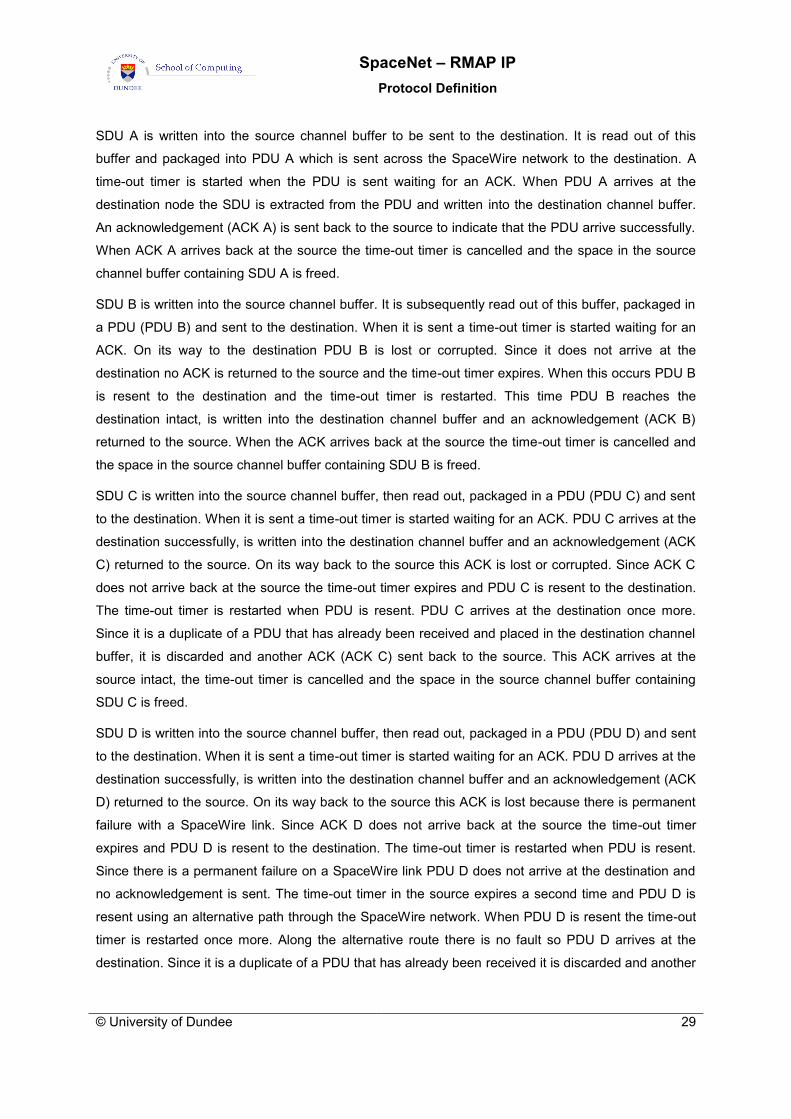
The retry mechanism is illustrated in Figure 3-7.
Source Destination
SDU A PDU A
SDU A
PDU B
Error
SDU B
SDU B
PDU D
ACK D
SDU D
Error
PDU B
ACK B
ACK A
SDU D
PDU D
Error
PDU D – Alt Route
ACK D – Alt Route
Time-out
Time-out
Time-out
PDU C
ACK C
SDU C
Error
SDU C
Time-outPDU C
ACK C
Figure 3-7 Retry Mechanism
SpaceNet – RMAP IP
Protocol Definition
© University of Dundee 29
SDU A is written into the source channel buffer to be sent to the destination. It is read out of this
buffer and packaged into PDU A which is sent across the SpaceWire network to the destination. A
time-out timer is started when the PDU is sent waiting for an ACK. When PDU A arrives at the
destination node the SDU is extracted from the PDU and written into the destination channel buffer.
An acknowledgement (ACK A) is sent back to the source to indicate that the PDU arrive successfully.
When ACK A arrives back at the source the time-out timer is cancelled and the space in the source
channel buffer containing SDU A is freed.
SDU B is written into the source channel buffer. It is subsequently read out of this buffer, packaged in
a PDU (PDU B) and sent to the destination. When it is sent a time-out timer is started waiting for an
ACK. On its way to the destination PDU B is lost or corrupted. Since it does not arrive at the
destination no ACK is returned to the source and the time-out timer expires. When this occurs PDU B
is resent to the destination and the time-out timer is restarted. This time PDU B reaches the
destination intact, is written into the destination channel buffer and an acknowledgement (ACK B)
returned to the source. When the ACK arrives back at the source the time-out timer is cancelled and
the space in the source channel buffer containing SDU B is freed.
SDU C is written into the source channel buffer, then read out, packaged in a PDU (PDU C) and sent
to the destination. When it is sent a time-out timer is started waiting for an ACK. PDU C arrives at the
destination successfully, is written into the destination channel buffer and an acknowledgement (ACK
C) returned to the source. On its way back to the source this ACK is lost or corrupted. Since ACK C
does not arrive back at the source the time-out timer expires and PDU C is resent to the destination.
The time-out timer is restarted when PDU is resent. PDU C arrives at the destination once more.
Since it is a duplicate of a PDU that has already been received and placed in the destination channel
buffer, it is discarded and another ACK (ACK C) sent back to the source. This ACK arrives at the
source intact, the time-out timer is cancelled and the space in the source channel buffer containing
SDU C is freed.
SDU D is written into the source channel buffer, then read out, packaged in a PDU (PDU D) and sent
to the destination. When it is sent a time-out timer is started waiting for an ACK. PDU D arrives at the
destination successfully, is written into the destination channel buffer and an acknowledgement (ACK
D) returned to the source. On its way back to the source this ACK is lost because there is permanent
failure with a SpaceWire link. Since ACK D does not arrive back at the source the time-out timer
expires and PDU D is resent to the destination. The time-out timer is restarted when PDU is resent.
Since there is a permanent failure on a SpaceWire link PDU D does not arrive at the destination and
no acknowledgement is sent. The time-out timer in the source expires a second time and PDU D is
resent using an alternative path through the SpaceWire network. When PDU D is resent the time-out
timer is restarted once more. Along the alternative route there is no fault so PDU D arrives at the
destination. Since it is a duplicate of a PDU that has already been received it is discarded and another

SpaceNet – SpaceWire-RT
Protocol Definition
30 © University of Dundee
acknowledgement (ACK D) returned to the source. Travelling over the alternative route the ACK
arrives safely at the source, the time-out timer is cancelled and the space in the source channel buffer
containing SDU D is freed.
As well as providing sequential retry where a duplicate PDU is sent if the ACK for a PDU fails to arrive
before the time-out timer expires, SpaceWire-RT provides simultaneous retry. This is illustrated in
Figure 3-8.
Source Destination
SDU A PDU A - Primary
SDU A
PDU B - Primary
Error
SDU B
SDU B
PDU C - Primary
ACK C - Primary
SDU C
Error
ACK A - Primary
SDU C
PDU C - Alternative
Error
Fail SDU C
PDU A - Alternative
ACK A - Alternative
PDU B-Alternative
ACK B - Alternative
Figure 3-8 Simultaneous Retry
The source user application puts SDU A into the source channel buffer to send to the destination.
Assuming that there is space in the destination channel buffer for the SDU it is packaged into a PDU
and sent to the destination twice using different paths (PDU A – primary and PDU A – Alternative).
When these PDUs are sent a single time-out timer is started waiting for an acknowledgement. In
Figure 3-8 PDU A – Primary arrives at the destination, SDU A is extracted and put in the destination
channel buffer and an acknowledgement (ACK A – Primary) returned to the source. Shortly after PDU
A – Primary starts to arrive, PDU A – Alternative arrives. This PDU is a duplicate of PDU A – Primary
so is discarded and an acknowledgement (ACK A – Alterative) is sent back to the source. Assuming
ACK A – Primary arrives at the source first it cancels the acknowledgement time-out timer and frees
the space used by SDU A in the source channel buffer. When ACK A – Alternative arrives it is
ignorded since the time-out timer has been cancelled already.

SpaceNet – RMAP IP
Protocol Definition
© University of Dundee 31
SDU B is placed in the source channel buffer next. It is subsequently sent in two PDUs to the
destination (PDU B – Primary and PDU B – Alternative) and a time-out timer is started waiting for an
acknowledgement. PDU B – Primary is lost or corrupted on the way, but there is no problem on the
alternative path so PDU B – Alternative arrives at the destination and SDU B is extracted and placed
in the destination channel buffer. ACK B – Alternative is returned to the source arriving there without
misfortune and causing the time-out timer to be cancelled and the space for SDU B in the source
channel buffer to be freed.
SDU C is the next SDU to be placed in the source channel buffer. Again two PDUs are sent and the
time-out timer started. PDU C – Primary is lost or corrupted on its way to the destination. PDU C –
Alternative arrives safely, SDU C is extracted and put in the destination channel buffer and ACK C –
Alternative sent back to the source. On its way to the source this PDU is lost or corrupted. Since no
acknowledgement is received at the source the timer-out timer expires and a failure indication is given
to the source user application indicating the failure to reliably deliver SDU C to the destination (even
though it was actually received in this case). Both primary and alternative paths failed in this example.
It is also possible to do the simultaneous retry over a single path. In this case a short interval should
be left between the two packets in case of an error covering the end of one packet and the start of the
next. Note: there is still a problem if the EOP of the first packet goes missing. The sending of an
empty packet between simultaneous retry packets could be considered to avoid this failure case.
The handling of retries in a resource reserved system is illustrated in Figure 3-9.

SpaceNet – SpaceWire-RT
Protocol Definition
32 © University of Dundee
Source Destination
SDU A Ch 10
PDU B Ch 25
SDU B Ch 25Slot 2
Slot 3
Slot4
Slot 5
Slot 6
Channel to slot mapping
Ch 3 -> Slot 5
Ch 10 -> Slot 4 and Slot 7
Ch 25 -> Slot 2 and Slot 6
SDU B Ch 25
SDU C Ch 3ACK B
SDU A Ch 10
PDU A Ch 10
ACK A
PDU C Ch 3
ErrorPDU C Ch 3
SDU C Ch 3ACK C
SDU D Ch 25
SDU D Ch 25PDU D Ch 25
ACK C
Figure 3-9 Time-Slot Retry
The system bandwidth is split up into a series of time-slots. A schedule is used to determine which
channel is allowed to send information during each time-slot. Part of the schedule giving the channel
to slot mapping is shown in Figure 3-9. The source user application submits several SDUs for
transmission over various channels (e.g. SDU B over channel 25). When time-slot 2 arrives which
channel 25 is mapped to, PDU B containing SDU B is transferred. It arrives at the destination and
SDU B is extracted from PDU B and put in the destination channel buffer related channel 25. An
acknowledgement (ACK B) is sent back to the source, travelling in the same time-slot as PDUB. ACK
B arrives at the source indicating that PDU B was delivered successfully.
In time-slot 4 channel 10 is allowed send a PDU. SDU A is encapsulated into PDU A and transferred
across the SpaceWire network. SDU A is extracted from the PDU and placed into the destination
channel buffer related to channel 10. ACK A is returned to the source.
In time-slot 5 channel 3 has access to the SpaceWire network. SDU C is encapsulated into PDU C
and sent across the network. Unfortunately it is lost or corrupted on its way across the network. This
means that no ACK C is received back at the source. A time-out timer waiting for the ACK expires so
PDU C is resent. This time PDU C reaches the destination and an acknowledgement (ACK C) is
returned to the source. The time-out timer is cancelled when ACK reaches the source. The time-slot
has to be long enough for the source to send a PDU, time-out waiting for the acknowledgement,
resend the PDU and once more wait for the ACK for the complete time-out period.

SpaceNet – RMAP IP
Protocol Definition
© University of Dundee 33
It is important to note that when providing reliable, timely delivery of PDUs the time needed to send
any retries have to be considered when defining the delivery schedule.
3.5.5 Error detection
Error detection is needed to support the retry function and also for error notification for the Best Effort
and Resource Reserved classes of traffic. There are six possible types of error:
Packet received with header error i.e. the header CRC has detected an error in the header.
Packet delivered to wrong destination i.e. the destination SpaceWire logical address does not
correspond to the SpaceWire address of the node that it has been delivered to.
Packet received with data error i.e. the data CRC has detected an error in the data field.
Missing packet detected using sequence numbers i.e. the sequence number of the packet
received from a specific source logical address is not one more than the previous packet
received from that address. Note that immediately after reset of a SpaceWire node any
sequence number is acceptable in a received packet. Sequence number incrementation is
considered after the first packet is received from a specific source address.
Duplicated packet received i.e. two packets with the same sequence number are received.
Note that since the sequence number is an eight-bit number sequence numbers will roll over
every 256 packets. Duplicate packet numbers must therefore occur within a certain number of
packets, specifically within two times the maximum number of outstanding packets. Sequence
number incrementation and checking is, of course, modulo 256.
SpaceWire Error End of Packet Error (EEP) i.e. somewhere on the path from source to
destination a SpaceWire link error (parity, disconnect, credit or escape error) has occurred
resulting in the packet being terminated prematurely by an EEP.
For the Best Effort and Resource Reserved QoS there is no retry in the event of an error. In this case
when an error occurs it is simply logged and optionally reported at the receiving node. Duplicate
packets are discarded.
For the Assured and Guaranteed QoS errors are logged at the receiver even when they are
recovered by the retry mechanism. Persistent errors are logged separately and flagged to the user
application. Duplicate packets are discarded.
3.5.6 Redundancy Function
The Redundancy Model adopted by SpaceWire-RT is that of alternative paths from a source node to
a destination node across a SpaceWire network. SpaceWire-RT supports autonomous switching
between alternative paths. These alternative paths may be used in one of three ways:

SpaceNet – SpaceWire-RT
Protocol Definition
34 © University of Dundee
Sending data over both paths at the same time, which is referred to as simultaneous retry.
Sending over the prime path and then if there is a failure using the redundant path.
Sending over either path and if there is a failure of one path all traffic goes over the remaining
path.
The path through the SpaceWire network may be defined using SpaceWire path addressing, logical
addressing, regional addressing, or any appropriate combination of these addressing methods.
These three approaches may all be implemented autonomously, with SpaceWire-RT providing
automatic redundancy switching in the event of a failure. Alternatively redundancy switching may be
centrally managed by either specifying a path that can be used for sending from a source to a
destination and changing this path specification in the event of a failure being detected, or by
reconfiguring the routing tables in the SpaceWire network to reroute the traffic avoiding the faulty
links.
The parameters that control the redundancy switching are:
Number of attempts on prime path (Np)
Number of attempts on redundant path (Nr)
Number of attempts on other alternative paths when appropriate (Na)
Simultaneous retry on/off
When simultaneous retry is off SpaceWire-RT will first send a PDU on the prime path. If this fails it will
the retry Np-1 times on the prime path. If there is still no success then it will try up to Nr attempts to
send the PDU on the redundant path. When appropriate, further alternative paths may be tried. Once
all retries have been attempted then the persistent error is reported to the local host system.
3.5.7 Address Translation
SpaceWire can provide up to 223 logical addresses, permitting up to 223 separate nodes. This
number is adequate for most foreseen space missions, so for SpaceWire-RT node identification will
use the SpaceWire logical address. Path addressing may be used to route a packet to its destination
but the node identification is done using the logical address.
A SpaceWire logical address is used to uniquely identify a node attached to the SpaceWire network.
A node may be identified by more than one SpaceWire logical address, but there is only one node
that has a specific logical address. For example node A can be identified by SpaceWire logical
addresses 124 and 125, but logical address 132 cannot be used to identify both node B and node C
(at the same time).
SpaceNet – RMAP IP
Protocol Definition
© University of Dundee 35
The address translation function translates from the SpaceWire logical address to the SpaceWire
address that will be used to send the packet across the network. The SpaceWire address can be a
path, logical, or regional logical address or an address constructed using any combination of these
addressing modes. The type of address used will be dependent upon the redundancy approach being
used. Address resolution is used to determine the SpaceWire address bytes that are included in the
header of the SpaceWire packet to route it along the required path across the SpaceWire network to
its intended destination.
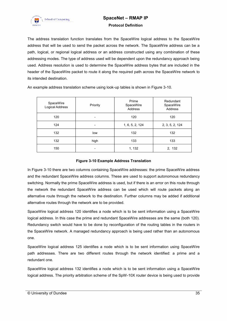
An example address translation scheme using look-up tables is shown in Figure 3-10.
SpaceWire
Logical Address
120
124
132
132
Prime
SpaceWire
Address
Redundant
SpaceWire
Address
120 120
1, 6, 5, 2, 124 2, 3, 5, 2, 124
132 132
133 133
Priority
-
-
low
high
150 1, 132 2, 132-
Figure 3-10 Example Address Translation
In Figure 3-10 there are two columns containing SpaceWire addresses: the prime SpaceWire address
and the redundant SpaceWire address columns. These are used to support autonomous redundancy
switching. Normally the prime SpaceWire address is used, but if there is an error on this route through
the network the redundant SpaceWire address can be used which will route packets along an
alternative route through the network to the destination. Further columns may be added if additional
alternative routes through the network are to be provided.
SpaceWire logical address 120 identifies a node which is to be sent information using a SpaceWire
logical address. In this case the prime and redundant SpaceWire addresses are the same (both 120).
Redundancy switch would have to be done by reconfiguration of the routing tables in the routers in
the SpaceWire network. A managed redundancy approach is being used rather than an autonomous
one.
SpaceWire logical address 125 identifies a node which is to be sent information using SpaceWire
path addresses. There are two different routes through the network identified: a prime and a
redundant one.
SpaceWire logical address 132 identifies a node which is to be sent information using a SpaceWire
logical address. The priority arbitration scheme of the SpW-10X router device is being used to provide

SpaceNet – SpaceWire-RT
Protocol Definition
36 © University of Dundee
preferential routing of packets destined for this node. SpaceWire logical address 132 is set up in the
routers with low priority and address 133 with high priority. Both have the same routing information.
When information is to be sent using the high priority route the priority parameter is set high and
SpaceWire address 133 is used. A managed approach to redundancy switching is used.
SpaceWire logical address 150 identifies a node which is to be sent information using a SpaceWire
logical address. In this case autonomous redundancy switching is to be used. To accommodate this
the port that is used to start a packet on either the prime or redundant path is included in the
SpaceWire address. Thereafter the routing tables in the routers route the packet through alternative
paths through the network to the destination.
When simultaneous retries are used then the information is sent in two packets at the same time one
using the prime SpaceWire address and the other using the redundant SpaceWire address.
3.5.8 Encapsulation
The encapsulation function encapsulates PDUs, ACKs, BFCTs and BACKs into SpaceWire packets.
3.5.8.1 PDU Encapsulation
The PDU encapsulation function encapsulates the SDU and associated parameters into a SpaceWire
packet. The PDU extraction function extracts the SDU from a SpaceWire packet.
The PDU encapsulation is illustrated in Figure 3-11 and Figure 3-12.
Destination
SpW Address
Destination
Logical Address
SpW
Protocol IDChannel
Source
Logical Address
Type /
RedundancyData Length
Destination
SpW Address
Destination
SpW Address
Sequence
Number
Data Data Data
Data Data Data Data
Data Data Data Data
Data Data Data Data
CRC MS CRC LS
First octet sent
Last octet sent
EOP
Data
Header CRC
Figure 3-11 PDU Encapsulation
The field of the PDU are described below:

SpaceNet – RMAP IP
Protocol Definition
© University of Dundee 37
The destination SpaceWire address is a variable length field that contains the SpaceWire path
and/or regional logical address that routes the packet across the SpaceWire network to the required
destination.
The destination logical address is a one byte field containing the logical address of the destination
node.
The protocol identifier is a one byte field containing the SpaceWire-RT protocol identifier value
(0x03).
The type field is an eight bit field comprising the following sub-fields:
The packet type is a two bit field containing the type of packet (PDU, ACK, BFCT or BACK).
The redundancy field is two bit field that identifies which path (prime, redundant, other) the
PDU or control code is taking through the SpaceWire network. An ACK or BACK should use
the same redundancy path as the corresponding PDU or BFCT.
The other four bits in the type field are reserved and are set to zero.
The source logical address is a one byte field that identifies the SpaceWire node sending the packet
by its logical address.
The sequence number is a one byte field containing an 8-bit sequence count used to detect missing
PDUs and BFCTs. There is a separate sequence count for each channel and for PDUs and BFCTs
within a channel.
The data length is a one byte field that specifies the number of data bytes in the data field.
The header CRC is a one byte field containing an 8-bit CRC covering the header of the packet. This
uses the same CRC format as the SpaceWire RMAP standard (ECSS-E50-11). The header CRC
covers the header from the Destination Logical Address to the byte immediately prior to the header
CRC. It does not include the Destination SpaceWire Address as this is deleted during passage
through the SpaceWire network. The header CRC is used to check that the header is correct before
the packet is processed. If there is an error in the header the entire packet is discarded.
The data field is a variable length field containing up to 255 data bytes.
The data CRC field contains a 16-bit CRC covering the data field only. This is used to confirm that the
data has been delivered without error.
The end of packet marker is a SpaceWire control code that indicates the end of the SpaceWire
packet and the start of the next one.
3.5.8.2 Control Code Encapsulation
The encapsulation of control codes (ACKs, BFCTs, and BACKs) is illustrated in Figure 3-12

SpaceNet – SpaceWire-RT
Protocol Definition
38 © University of Dundee
Destination
SpW Address
Destination
Logical Address
SpW
Protocol ID
Sequence
NumberType = ACK,
BFCT or BACK
Reserved
= 0Header CRC
Destination
SpW Address
Destination
SpW Address
First octet sent
Last octet sentEOP
ChannelSource
Logical Address
Figure 3-12 Control Code Encapsulation
The control code encapsulation is similar to the PDU encapsulation. There is no data field and no
data CRC. The date length field in the PDU becomes a reserved field set to zero in the control code.
3.5.9 Source Channel Arbitration
Source channels have to compete for access to the SpaceWire network. Only one of them can have
access to a SpaceWire link at any particular time to send a PDU. There are two mechanisms for
deciding which source channel buffer with data to send to a destination channel buffer with space for
that data gets the opportunity to send a PDU: priority and scheduling.
3.5.10 Priority
Priority is provided for both asynchronous and synchronous systems, thus it is used in all four
qualities of service.
A separate source channel buffer and destination channel buffer are used for each level of priority to
be supported for each destination. A PDU will be sent from a source channel buffer with a lower
channel number before sending a PDU from a source channel buffer with a high channel number. The
source channel buffers are allocated to destination and priority levels bearing this is mind. For
example if there are four destinations (logical addresses 49, 62, 75 and 112) that a source needs to
send information to and it wants to have three priority levels (low, medium, high) for communication to
each of these destinations then the example channel allocation scheme shown in Table 3-3 can be
used.

SpaceNet – RMAP IP
Protocol Definition
© University of Dundee 39
Table 3-3 Example Channel Numbering for Priority Arbitration
Channel Number Destination Priority
1 49 High
2 62 High
3 75 High
4 112 High
5 49 Medium
6 62 Medium
7 75 Medium
8 112 Medium
9 49 Low
10 62 Low
11 75 Low
12 112 Low
Channel 1 is used for high priority traffic to the destination with logical address 49.
The source user application puts information into an appropriate source channel buffer depending on
where it wants to send the data (destination) and the priority of the data. For example to send data
with low priority from the source to the destination with logical address 75, the data is written into
source channel buffer 11. SpaceWire-RT will then transfer this information across the SpaceWire
network when there is room in the destination channel buffer and after other higher priority traffic with
space in its destination buffers has been transferred.
Note that the retry/no-retry selection is also defined on a channel by channel basis.
Note a priority scheme where the priority for each channel is explicitly declared rather than being the
same as the channel number will also be considered. This is easier to manage but more difficult to
implement in hardware.
3.5.11 Scheduling
Scheduling is provided for synchronous systems only. It is used to support resource reserved and
guaranteed qualities of service. The network bandwidth is separated using time-division multiplexing

SpaceNet – SpaceWire-RT
Protocol Definition
40 © University of Dundee
into a series of repeating time-slots. A schedule table is used in each source to specify in which
source channel buffer(s) are allowed to send information during each time-slot. The schedule tables in
every source are devised to avoid conflicts on the network. Only one source is allowed to send
information at a time, or multiple sources can send information at the same time provided that they do
not use any common network resource i.e. send information over the same link.
An example schedule table is shown in Table 3-4.
Table 3-4 Example Schedule Table
Time-slot Channel
0 32
1 -
2 12
3 1
...
62 5
63 -
During time-slot 0 channel 32 is allowed to send a PDU. During time-slot 1 no channel is allowed to
send a PDU (presumably another source is scheduled to send a PDU in this time-slot.
Scheduling can be combined with priority so that several channels all to the same destination and
using the same network resources for communication but with different priority levels are mapped on
to time-slot. When the time-slot arrives, the highest priority channel (the one with the lowest channel
number) which has data to send and room in its destination buffer, is sent first. An example schedule
table with priority is illustrated in Table 3-5.

SpaceNet – RMAP IP
Protocol Definition
© University of Dundee 41
Table 3-5 Example Schedule Table with Priority
Time-slot Channel
0 32, 64, 96
1 -
2 12
3 10, 20, 30, 40
...
62 5
63 -
In time-slot 0 three levels of priority are supported using channels 32, 64 and 96. Time-slot 2 has only
one level of priority. Time-slot 3 has four levels of priority provided by channels 10, 20, 30, 40. If a
packet of high priority is to be sent to the destination supported by these channels then it is written in
source channel buffer 10 and will be sent before any PDUs in channels 20, 30 or 40, provided that
there is room in the destination channel buffer associated with source channel buffer 10.

SpaceNet – SpaceWire-RT
Protocol Definition
42 © University of Dundee
4 USER APPLICATION INTERFACE
4.1 SOURCE USER INTERFACE
a) The source user interface shall consist of one or more source channel buffers.
b) Each source channel buffer shall have associated with a destination channel buffer in a
destination node.
c) The prime and any alternative routes to the destination node shall be associated with the
source channel buffer.
d) Priority level and retry enable/disable QoS parameters shall be associated with the source
channel buffer.
e) The source channel buffer shall indicate to the source user application interface when it has
room for more information to send to the destination channel buffer.
f) The source user application shall write data to be sent to the destination channel buffer into
the source channel buffer associated with that destination channel buffer.
g) When a complete user application data unit has been written into a source channel buffer the
source user application shall indicate to the source channel buffer that the end of a user
application data unit has been reached. This is so that the contents can be transferred as
soon as possible without waiting for more data to be put into the source channel buffer.
4.2 DESTINATION USER INTERFACE
a) The destination user interface shall consist of one or more destination channel buffers.
b) Each destination channel buffer shall be associated with a source channel buffer in a source
node.
c) Priority level and retry enable/disable QoS parameters shall be associated with the
destination channel buffer, matching those of the corresponding source channel buffer.
d) The destination channel buffer shall indicate to the destination user application when it has
data available.
e) The destination user application shall read data from the destination channel buffer.
f) The destination channel buffer shall indicate to the destination user application when a
complete user application data unit has been read out of the destination channel buffer.
SpaceNet – RMAP IP
Protocol Definition
© University of Dundee 43
5 SEGMENTATION
a) Data in a source channel buffer shall be split up into service data units (SDUs) no larger than
the maximum SDU size of 255 bytes.
b) Each SDU shall be encapsulated in a PDU for transferring across the SpaceWire network.
c) An SDU shall be put into a PDU and sent across the network whenever there is room in the
destination buffer for a complete maximum size PDU, and when there is either
a. 255 or more bytes of user data in the source channel buffer
b. Less than 255 bytes of user data followed by an end of user data character.

SpaceNet – SpaceWire-RT
Protocol Definition
44 © University of Dundee
6 END TO END FLOW CONTROL
a) A source channel buffer shall only request to send data to a destination channel buffer when
there is room for the maximum size SDU (255 bytes) in the destination channel buffer.
b) The destination channel buffer shall signal that space is available for another maximum size
SDU by sending a buffer flow control token to the source channel buffer associated with the
destination channel buffer.
c) The buffer flow control token shall contain the logical address of the destination node that
contains the destination channel buffer, the channel number of the destination channel buffer,
and a sequence number.
d) The sequence number shall increment each time enough space for a further maximum size
SDU becomes available in the destination channel buffer and an BFCT to indicate this is sent
to the source node containing the source channel buffer that is sending data to the destination
channel buffer.
e) The sequence number shall be an 8-bit count.
f) The sequence number shall wrap round to 0 when the maximum value (255) is reached.
g) When an BFCT is sent a time-out timer shall be started waiting on the arrival of a BACK.
h) When an BFCT arrives at the source node it shall be passed to the source channel buffer
identified by the destination logical address and channel number contained in the BFCT.
i) The source channel buffer shall keep a note of the sequence number of the last BFCT it
received.
j) The source channel buffer shall keep a note of the amount of available space in the
destination channel buffer.
k) If the sequence number of the BFCT received is greater or equal to the sequence number of
the last BFCT received then the source channel buffer
a. Shall update its record of the amount of available space in the destination channel
buffer accordingly,
b. Shall send an acknowledgement to the BFCT (BACK) containing the sequence
number of the BFCT received.
l) If the sequence number of the BFCT received is less than the sequence number of the last
BFCT received then the source channel buffer shall ignore the BFCT as it is a duplicate of a
previously sent BFCT.

SpaceNet – RMAP IP
Protocol Definition
© University of Dundee 45
m) When a BACK is received at a node it shall be passed to the appropriate destination channel
buffer as determined by the channel number.
n) The destination channel shall keep a record of the sequence number of the last BACK
received.
o) If the sequence number of the BACK is greater than the sequence number of the last BACK
received,
a. The timers for all BFCTs with sequence numbers from one more than the last BACK
received to the BACK just received shall be cancelled,
b. The record of the sequence number of the last BACK received shall be updated to
the sequence number of the BACK just received.
p) If an BFCT time-out timer expires,
a. An BFCT shall be sent with the same sequence number as that for which the timer
was started,
b. The time-out timer shall be restarted.
q) If a timer-out timer for an BFCT expire more that a maximum allowed number of times the
local host system shall be informed of the error.

SpaceNet – SpaceWire-RT
Protocol Definition
46 © University of Dundee
7 RETRY
7.1 TYPES OF ERROR:
The SOIS SpaceWire receiver shall detect the following types of error:
Packet received with header error
Packet delivered to wrong destination or with wrong SpaceWire Protocol ID
Packet received with data error
Missing packet
Duplicate packet
SpaceWire Error End of Packet Error (EEP)
7.2 CRC GENERATION AND CHECKING:
a) The header CRC shall be an 8-bit CRC which is the same as used for RMAP.
b) The header CRC shall cover all bytes in the header from the destination logical address to
and including the byte immediately prior to the header CRC.
c) The data CRC shall be a 16-bit CRC.
d) The data CRC shall cover all data bytes in the data field.
7.3 SENDING A PDU
a) Each source channel buffer shall have a last sent sequence number variable which shall hold
the sequence number of the last PDU sent from that source channel buffer.
b) Each source channel buffer shall have a last acknowledged sequence number variable which
shall hold the sequence number of the last PDU that has been acknowledged.
c) After power up or reset the last sent and last acknowledged sequence number variables shall
be set to zero so that the sequence number of the first PDU sent from each channel shall be
one.
d) When the source channel buffer has an SDU ready to send and there is room for it in the
destination channel buffer, it shall request for it to be sent it with the next sequence number
for that channel i.e. the sequence number will be one more (modulo 256) than that of the last
sequence number variable for that channel.
e) When a PDU is sent, a timeout timer shall be started waiting for an acknowledgement from
that packet.

SpaceNet – RMAP IP
Protocol Definition
© University of Dundee 47
f) When a PDU is sent, the last sent sequence number shall be incremented so that it contains
the sequence number of the last PDU sent.
g) The space in the source channel buffer for the SDU sent shall not be freed until an
acknowledgement has been received for the corresponding PDU.
h) The source channel buffer shall send no more than a maximum number of outstanding
(unacknowledged) PDUs before receiving acknowledgements for them.
i) Once this limit is reached the source shall not send any more packets until one or more
acknowledgements have been received.
j) The maximum number of outstanding packets shall be a management parameter.
7.4 RECEIVING A PDU
a) When a PDU is received without error and its sequence number is one more than the last
received sequence number for the destination channel buffer and there is room in the
destination channel buffer specified by the source logical address and channel number in the
PDU:
i. The SDU shall be extracted from the PDU and placed in the destination channel
buffer.
ii. An acknowledgement shall be sent to the source of the PDU containing:
a. The logical address of the source that sent the PDU being
acknowledged,
b. The logical address of the destination that received the PDU and is
sending the acknowledgement,
c. The channel number from the PDU, i.e. the channel number in the
source,
d. The sequence number from the PDU.
iii. The last received sequence number variable in the destination channel buffer
shall be updated to the sequence number of the PDU just received.
7.5 RECEIVING A PDU WHEN THE DESTINATION CHANNEL BUFFER IS FULL
a) When a PDU is received without error and there is no room in the destination channel buffer
specified by the source logical address and channel number:
i. The PDU shall be discarded.

SpaceNet – SpaceWire-RT
Protocol Definition
48 © University of Dundee
ii. The error shall be logged as a flow control error.
7.6 RECEIVING A PACKET CONTAINING ERRORS
a) When a packet is received with a header error indicated by the header CRC, or by an EOP or
EEP being received before the header CRC is received:
i. The packet shall be discarded,
ii. The error shall be logged as a header error.
b) When a packet is received with a correct header CRC but the destination logical address
does not match a logical address accepted by the destination node:
i. The packet shall be discarded,
ii. The error shall be logged as an invalid destination error.
c) When a packet is received with a correct header CRC, but the source logical address is not
one that the destination node accepts data from:
i. The packet shall be discarded,
ii. The error shall be logged as an invalid source error.
d) When a packet is received with a correct header CRC, but the combination of the source
logical address and the channel number does not identify a destination channel buffer:
i. The packet shall be discarded,
ii. The error shall be logged as an invalid channel error.
e) When a packet is received with a correct header CRC, but the sequence number is not equal
to or one more than the value of the last received sequence number:
i. The packet shall be discarded,
ii. The error shall be logged as an out of sequence error.
f) When a packet is received with a correct header CRC, but the sequence number is equal to
the value of the last received sequence number:
i. The packet shall be discarded,
ii. The occurrence of a duplicate packet shall be logged.
g) When a PDU is received without a header CRC error and its sequence number is one more
than the last received sequence number for the destination channel buffer and there is room
in the destination channel buffer specified by the source logical address and channel number
SpaceNet – RMAP IP
Protocol Definition
© University of Dundee 49
in the PDU but a data CRC is detected after the SDU has been written to the destination
channel buffer:
i. The PDU shall be discarded,
ii. The SDU shall be removed from the destination channel buffer,
iii. The error shall be logged as a data CRC error.
h) When a PDU is received without a header CRC error and its sequence number is one more
than the last received sequence number for the destination channel buffer and there is room
in the destination channel buffer specified by the source logical address and channel number
in the PDU but an EOP occurs before the data CRC:
i. The PDU shall be discarded,
ii. Any data written to the destination channel buffer from this PDU shall be removed,
iii. The error shall be logged as an early EOP error.
i) When a PDU is received without a header CRC error and its sequence number is one more
than the last received sequence number for the destination channel buffer and there is room
in the destination channel buffer specified by the source logical address and channel number
in the PDU but an EOP occurs before or immediately after the data CRC:
i. The PDU shall be discarded,
ii. Any data written to the destination channel buffer from this PDU shall be removed,
iii. The error shall be logged as an EEP error.
j) When a PDU is received without a header CRC error and its sequence number is one more
than the last received sequence number for the destination channel buffer and there is room
in the destination channel buffer specified by the source logical address and channel number
in the PDU but the data field is larger than specified in the data length field:
i. The PDU shall be discarded,
ii. Any data written to the destination channel buffer from this PDU shall be removed,
iii. The error shall be logged as a data length error.
7.7 RECEIVING AN ACKNOWLEDGEMENT:
a) When an acknowledgement is received it shall be passed to the appropriate source channel
buffer as determined by the channel number.

SpaceNet – SpaceWire-RT
Protocol Definition
50 © University of Dundee
b) The destination logical address in the acknowledgement shall be checked against the
destination for the source channel buffer.
c) If the destination logical address in the acknowledgement does not match the destination for
the source channel buffer,
i. The acknowledgement shall be discarded
ii. The error shall be logged as an ACK destination error.
d) If the sequence number in the acknowledgement is greater than the last acknowledged
sequence number and less than or equal to the last sent acknowledgement,
i. Each SDU with a sequence number greater than the last acknowledged sequence
number and less than or equal to the sequence number of the acknowledgement:
i. Shall have its time-out timer cancelled
ii. Shall have the space in the source channel buffer for the SDU freed
ii. The last acknowledged sequence number variable shall be set to the sequence
number of the acknowledgement.
e) If the sequence number in the acknowledgement is less than or equal to the last
acknowledged sequence number and less than or equal to the last sent acknowledgement,
i. The acknowledgement shall be discarded,
ii. The occurrence of a duplicate acknowledgement shall be logged.
f) If the sequence number in the acknowledgement is greater than the last sent
acknowledgement,
i. The acknowledgement shall be discarded,
ii. An invalid acknowledgement sequence number shall be recorded.
7.8 ACKNOWLEDGEMENT TIME-OUT:
a) When an acknowledgement time-out timer expires,
i. All acknowledgement time-out timers that are still running waiting for
acknowledgements for PDUs sent from the source channel buffer shall be cancelled.
ii. The unacknowledged PDUs for the channel shall be resent.
iii. Acknowledgement time-out timers shall be started for all PDUs resent.
iv. A retry count variable for the channel shall be incremented.

SpaceNet – RMAP IP
Protocol Definition
© University of Dundee 51
7.9 RETRY COUNT:
a) The retry count shall determine over which path the resent packets are sent when automatic
redundancy switching is enabled.
b) The retry count shall be used to flag to the network management system when failure of a
path through a network has been detected.
c) If in the source the retry count for a channel ever equals the Retry Prime Limit managed
parameter, then it is assumed that the prime path through the network from the source to the
destination has failed. This shall be logged and flagged as a prime retry failure at the source.
d) If automatic redundancy switching is enabled and the retry count equals the Retry Prime
Limit, the source shall start to send and resend all packets to the destination over the
redundant route to the destination.
e) If automatic redundancy switching is not enabled and the retry count equals the Retry Prime
Limit, then the source shall cease sending and resending all packets over the channel that
has failed to deliver packets.
NOTE: It is then up to network management to switch to a redundant path or logical
address and to re-enable packet transmission to the destination.
f) If in the source the retry count for a channel ever exceeds the Retry Redundant Limit
managed parameter then it is assumed that the redundant path through the network from the
source to the destination has failed:
a. This shall be logged and flagged as a redundant retry failure at the source
b. The source channel buffer shall then cease sending any packets until told that it may
resume sending to the failed destination by network management.
g) The Retry Redundant Limit shall not be set to a value less than or equal to the Retry Prime
Limit.

SpaceNet – SpaceWire-RT
Protocol Definition
52 © University of Dundee
8 REDUNDANCY
8.1 REDUNDANCY MANAGEMENT
a) Automatic redundancy switching shall be enabled by management parameter.
b) In the source node the address translation table shall determine the prime and redundant for
each channel.
c) There may be more than two levels of redundancy (e.g. primary, secondary and tertiary
paths) which shall be implemented by extending the address translation table accordingly.
d) A parameter (active path) shall determine which is the active path (or logical address) to use
for each destination.
e) The active path parameter shall be set to prime on system reset or power up.
f) It shall be possible for network management to set the active path parameter at any time.
g) If automatic redundancy switching is enabled then the active path parameter may be altered
from prime to redundant when the retry count equals the Retry Prime Limit.
h) A parameter (enable sending) for each channel shall be used to enable or disable the sending
of data over the corresponding channel.
i) The enable sending parameter shall be set to enable on system reset or power up.
j) It shall be possible for network management to set the enable sending path parameter at any
time.
k) When automatic redundancy switching is not enabled then if the retry count reaches the Retry
Prime Limit for a particular channel then the enable sending parameter for the channel shall
be set to disabled to stop further sending of data over that channel, until subsequent
intervention by the network management system.
l) If the retry count reaches the Retry Redundant Limit for a particular destination then the
enable sending parameter for the destination shall be set to disabled to stop further sending
of data to that destination, until subsequent intervention by the network management system.
8.2 RETRY AND REDUNDANCY FOR DIFFERENT TYPES OF SERVICE
In this section the retry and redundancy facilities provided for each type of service are summarised.
8.2.1 Best Effort
a) For the Best Effort service no retries shall be permitted.

SpaceNet – RMAP IP
Protocol Definition
© University of Dundee 53
b) Redundancy switching for the Best Effort service shall performed by network management
setting the active path and enable sending management parameter in source for each
destination that the source sends data to.
8.2.2 Assured
a) For the Assured service retries shall be permitted.
b) Redundancy switching for the Assured service shall be performed either automatically or by
network management.
8.2.3 Reserved
a) For the Reserved service no retries shall be permitted.
b) Redundancy switching for the Reserved service shall performed by network management
setting the active path and enable sending management parameter in source for each
destination that the source sends data to.
8.2.4 Guaranteed
a) For the Guaranteed service retries shall be permitted within the time-slot or bandwidth
allocated to the channel between source and destination.
b) Redundancy switching for the Guaranteed service shall be performed either automatically or
by network management.

SpaceNet – SpaceWire-RT
Protocol Definition
54 © University of Dundee
9 ADDRESS TRANSLATION
a) SpaceWire logical addresses shall be used to identify nodes on a SpaceWire-RT network.
b) The maximum number of nodes permitted shall be 223 which is the maximum number of
unreserved SpaceWire logical addresses.
c) A node may be identified by more than one SpaceWire logical address.
d) The address translation function shall translate from the SpaceWire logical address of a node
to a SpaceWire address that is used to send a SpaceWire packet across the network.
e) The SpaceWire address may be a SpaceWire path address, logical address, regional logical
address or an address constructed using any combination of these addressing modes.
f) An address translation table shall translate from the identity of the node that a SpaceWire
packet is to be sent to (i.e. its logical address) and its priority level to one or more SpaceWire
addresses.
g) There shall be SpaceWire addresses in the address translation table corresponding to the
primary paths through the SpaceWire network to the intended destination nodes.
h) There shall be SpaceWire addresses in the address translation table corresponding to each
set of alternative paths through the SpaceWire network to the intended destination nodes.

SpaceNet – RMAP IP
Protocol Definition
© University of Dundee 55
10 ENCAPSULATION
10.1 PDU
a) The PDU encapsulation function shall encapsulate a SDU and associated parameters into a
SpaceWire packet.
Note: The PDU encapsulation is illustrated in Figure 10-1.
Destination
SpW Address
Destination
Logical Address
SpW
Protocol IDChannel
Source
Logical Address
Type /
RedundancyData Length
Destination
SpW Address
Destination
SpW Address
Sequence
Number
Data Data Data
Data Data Data Data
Data Data Data Data
Data Data Data Data
CRC MS CRC LS
First octet sent
Last octet sent
EOP
Data
Header CRC
Figure 10-1 PDU Encapsulation
b) The PDU extraction function shall extract a SDU from a SpaceWire packet.
c) The destination SpaceWire address shall be a variable length field that contains the
SpaceWire path and/or regional logical address that routes the packet across the SpaceWire
network to the required destination.
d) The destination logical address shall be a one byte field containing the logical address of the
destination node.
e) The protocol identifier shall be a one byte field containing the SpaceWire-RT protocol
identifier value (0x03).
f) The type field shall be an eight bit field comprising the following sub-fields:
i. The packet type shall be a two bit field containing the type of packet (PDU, ACK,
BFCT or BACK).

SpaceNet – SpaceWire-RT
Protocol Definition
56 © University of Dundee
ii. The redundancy field shall be a two bit field that identifies which path (prime,
redundant, other) the PDU or control code is taking through the SpaceWire network.
iii. An ACK or BACK should use the same redundancy path as the corresponding PDU
or BFCT.
iv. The other four bits in the type field shall be reserved and set to zero.
g) The source logical address shall be a one byte field that identifies the SpaceWire node
sending the packet by its logical address.
h) The sequence number shall be a one byte field containing an 8-bit sequence count used to
detect missing PDUs and BFCTs. There is a separate sequence count for each channel and
for PDUs and BFCTs within a channel.
i) The data length shall be a one byte field that specifies the number of data bytes in the data
field.
j) The header CRC shall be a one byte field containing an 8-bit CRC covering the header of the
packet.
k) The header CRC shall use the same CRC format as the SpaceWire RMAP standard (ECSS-
E50-11).
l) The header CRC shall covers the header from the Destination Logical Address to the byte
immediately prior to the header CRC.
m) The header CRC shall not cover the Destination SpaceWire Address as this is deleted during
passage through the SpaceWire network.
n) The header CRC shall be used to check that the header is correct before the packet is
processed.
o) The data field shall be a variable length field containing up to 255 data bytes.
p) The data field shall contain the SDU.
q) The data CRC field shall contain a 16-bit CRC covering the data field only.
r) The data CRC shall be used to confirm that the data has been delivered without error.
s) The end of packet marker shall be a SpaceWire control code that indicates the end of the
SpaceWire packet and the start of the next one.
10.2 ACK
The encapsulation of control codes ACKs is illustrated in Figure 10-2.

SpaceNet – RMAP IP
Protocol Definition
© University of Dundee 57
Source
SpW Address
Source
Logical Address
SpW
Protocol ID
Sequence
NumberType = ACK
Reserved
= 0Header CRC
Source
SpW Address
Source
SpW Address
First octet sent
Last octet sentEOP
ChannelDestinaton
Logical Address
Figure 10-2 ACK Encapsulation
a) The source SpaceWire address shall be a variable length field that contains the SpaceWire
path and/or regional logical address that routes the acknowledgement across the SpaceWire
network back to the source of the PDU that is being acknowledged.
b) The source logical address shall be a one byte field containing the logical address of the
source of the PDU being acknowledged.
c) The source logical address shall be copied from the PDU.
d) The protocol identifier shall be a one byte field containing the SpaceWire-RT protocol
identifier value (0x03).
e) The type field shall be an eight bit field comprising the following sub-fields:
i. The packet type shall be a two bit field containing the type of packet i.e. an ACK.
ii. The redundancy field shall be a two bit field that identifies which path (prime,
redundant, other) the PDU or control code is taking through the SpaceWire network.
iii. The other four bits in the type field shall be reserved and set to zero.
f) The destination logical address shall be a one byte field that identifies the SpaceWire node
sending the acknowledgement by its logical address.
g) The destination logical address shall be copied from the PDU that is being acknowledged.
h) The sequence number shall be a one byte field containing the sequence number copied from
the PDU being acknowledged.
i) The reserved field shall be a one byte field that is set to zero.
j) The header CRC shall be a one byte field containing an 8-bit CRC covering the header of the
packet.

SpaceNet – SpaceWire-RT
Protocol Definition
58 © University of Dundee
10.3 BFCT
The encapsulation of control codes BFCTs is illustrated in Figure 10-3.
Source
SpW Address
Source
Logical Address
SpW
Protocol ID
BFCT Sequence
NumberType = BFCT
Reserved
= 0Header CRC
Source
SpW Address
Source
SpW Address
First octet sent
Last octet sentEOP
ChannelDestinaton
Logical Address
Figure 10-3 BFCT Encapsulation
a) The source SpaceWire address shall be a variable length field that contains the SpaceWire
path and/or regional logical address that routes the BFCT across the SpaceWire network to
the source of PDUs for the destination channel buffer that is sending the BFCT.
b) The source logical address shall be a one byte field containing the logical address of the
source of PDUs for the destination channel buffer that is sending the BFCT.
c) The protocol identifier shall be a one byte field containing the SpaceWire-RT protocol
identifier value (0x03).
d) The type field shall be an eight bit field comprising the following sub-fields:
i. The packet type shall be a two bit field containing the type of packet i.e. an BFCT.
ii. The redundancy field shall be a two bit field that identifies which path (prime,
redundant, other) the PDU or control code is taking through the SpaceWire network.
iii. The other four bits in the type field shall be reserved and set to zero.
e) The destination logical address shall be a one byte field that identifies the SpaceWire node
sending the BFCT by its logical address.
f) The BFCT sequence number shall be a one byte field containing an 8-bit sequence count
used to detect missing BFCTs.
g) The reserved field shall be a one byte field that is set to zero.
h) The header CRC shall be a one byte field containing an 8-bit CRC covering the header of the
packet.

SpaceNet – RMAP IP
Protocol Definition
© University of Dundee 59
10.4 BACK
The encapsulation of control codes BACKs is illustrated in Figure 10-4.
Destination
SpW Address
Destination
Logical Address
SpW
Protocol ID
BFCT Sequence
NumberType = BACK
Reserved
= 0Header CRC
Destination
SpW Address
Destination
SpW Address
First octet sent
Last octet sentEOP
ChannelSource
Logical Address
Figure 10-4 BACK Encapsulation
a) The destination SpaceWire address shall be a variable length field that contains the
SpaceWire path and/or regional logical address that routes the packet across the SpaceWire
network to the destination node containing the destination channel buffer that sent the BFCT
being acknowledged.
b) The destination logical address shall be a one byte field containing the logical address of the
destination node containing the destination channel buffer that sent the BFCT being
acknowledged.
c) The destination logical address shall be a copy of the destination logical address in the BFCT
that is being acknowledged.
d) The protocol identifier shall be a one byte field containing the SpaceWire-RT protocol
identifier value (0x03).
e) The type field shall be an eight bit field comprising the following sub-fields:
i. The packet type shall be a two bit field containing the type of packet i.e. a BACK.
ii. The redundancy field shall be a two bit field that identifies which path (prime,
redundant, other) the PDU or control code is taking through the SpaceWire network.
iii. The other four bits in the type field shall be reserved and set to zero.
f) The source logical address shall be a one byte field that identifies the SpaceWire node
sending the BACK by its logical address.
g) The source logical address shall be a copy of the source logical address in the BFCT that is
being acknowledged.

SpaceNet – SpaceWire-RT
Protocol Definition
60 © University of Dundee
h) The BFCT sequence number shall be a one byte field containing the BFCT sequence number
copied from the BFCT that is being acknowledged.
i) The reserved field shall be a one byte field that is set to zero.
j) The header CRC shall be a one byte field containing an 8-bit CRC covering the header of the
packet.

SpaceNet – RMAP IP
Protocol Definition
© University of Dundee 61
11 PRIORITY
a) A separate channel shall be used for each level of priority to be supported for each
destination.
b) Priority shall be associated with the channel number.
c) A PDU shall be sent from a source channel buffer with a lower channel number before
sending a PDU from a source channel buffer with a high channel number.

SpaceNet – SpaceWire-RT
Protocol Definition
62 © University of Dundee
12 RESOURCE RESERVATION
12.1 TIME-SLOTS
a) Time-slots boundaries shall be distributed using SpaceWire time-codes.
b) There shall be 64 time-slots each identified by the time value (0-63) in the SpaceWire time-
code.
c) Each time-slot starts on receipt of a time-code and ends on the receipt of the next time-code.
d) Time-codes shall be sent out at a uniform rate determined by a managed parameter, the time-
code rate.
e) An Epoch shall be defined as being 64 time-slots in length starting with time-slot 0 and ending
with time-slot 63.
f) Major cycles comprising several epochs may be implemented but are beyond the scope of
this specification.
12.2 RESOURCES AND CHANNELS
a) The use of the SpaceWire links shall be managed by the resource reservation mechanism.
b) The set of resources (source channel buffer, SpaceWire links, destination channel buffer)
required to send a packet from a source channel buffer to a destination channel buffer shall
be referred to as a channel and be uniquely identified by its source logical address and
channel number.
c) The source channel buffer related to a specific channel shall be identified by the channel
number.
d) The destination channel buffer related to a specific channel shall be identified by the source
logical address and the channel number i.e. there is a mapping in the destination from source
logical address and channel number in a PDU to the number of the destination channel
buffer.
12.3 BEST EFFORT AND ASSURED TRAFFIC
a) Best Effort and Assured traffic in a synchronous system shall be assigned channels in the
source, one for each destination address that they have to send information to. Best Effort
and Assured are effectively handled as Resource Reserved and Guaranteed traffic
respectively.

SpaceNet – RMAP IP
Protocol Definition
© University of Dundee 63
b) The channels for Best Effort and Assured traffic shall be included in the schedule or
bandwidth reservation table.
12.4 SCHEDULED SYSTEM
a) Channels shall be assigned to time-slots in such a way that there is no conflicting use of
resources i.e. none of the channels assigned to a particular time-slot may use the same
SpaceWire link. Note that this includes SpaceWire links in the middle of a SpaceWire
network.
b) The assignment of channels to time-slots shall be referred to as the schedule table.
c) When a specific time-slot starts, any source with a channel assigned to that time-slot may
send a packet.
d) For the guaranteed service operating over a scheduled system, retries shall be sent within
same time-slot as the original packet.
e) Retry shall thus be a go back one (send and wait) for a scheduled system.
f) The MDU that can be sent in a time-slot with the guaranteed service must be reduced to allow
time for the retry or retries to take place.
g) In a scheduled system all traffic shall be scheduled. Best-Effort and Assured traffic are
mapped to channels so they effectively become Resource Reserved and Guaranteed traffic.
The Best Effort and Assured services can still be used, but they are handled in a scheduled
system in the same way as Resource Reserved and Guaranteed traffic. Specifically time-slots
must be allocated for Best Effort and Assured communication.

SpaceNet – SpaceWire-RT
Protocol Definition
64 © University of Dundee
13 NETWORK CONFIGURATION PARAMETERS
a) The SpaceWire links shall be configured to AutoStart.
b) The routing tables in the SpaceWire router shall be configured by network management to
provide the required paths for SpaceWire logical addresses.
c) Configuration of SpaceWire routers shall be performed using the SpaceWire RMAP protocol
(ECSS-E50-11).
d) All SpaceWire links in the network shall be set to operate at the same data rate.
e) Automatic power-down on link silence may be enabled for SpaceWire links in the network to
save power when the traffic over the link is expected to be sporadic.

SpaceNet – RMAP IP
Protocol Definition
© University of Dundee 65
14 DOCUMENT CHANGES
The changes made this document are listed in this section.
Table 14-1: Changes to Document (Draft to Draft)
Section/Reference Change