Embed Size (px)
Citation preview

A SunCam online continuing education course
Spacecraft Subsystems Part 2 ‒
Fundamentals of Electrical Power
by
Michael A. Benoist, P.E.

Spacecraft Subsystems Part 2 ‒ Fundamentals of Electrical Power
A SunCam online continuing education course
www.SunCam.com Copyright 2017 Michael A. Benoist Page 2 of 36
Contents 1. Introduction ........................................................................................................................... 4
Sun Presence ............................................................................................................................... 6 Environmental Hazards ............................................................................................................... 7
2. Power Sources ..................................................................................................................... 11 Solar Arrays .............................................................................................................................. 11 Secondary Batteries .................................................................................................................. 14 Primary Batteries ...................................................................................................................... 17 Fuel Cells .................................................................................................................................. 19 Radioisotope Thermoelectric Generators ................................................................................. 21
3. Power Regulation ................................................................................................................ 26 Solar Array Power Control ....................................................................................................... 26 Solar Array Energy Transfer ..................................................................................................... 30
Spacecraft Subsystems Part 2 ‒ Fundamentals of Electrical Power
A SunCam online continuing education course
www.SunCam.com Copyright 2017 Michael A. Benoist Page 3 of 36
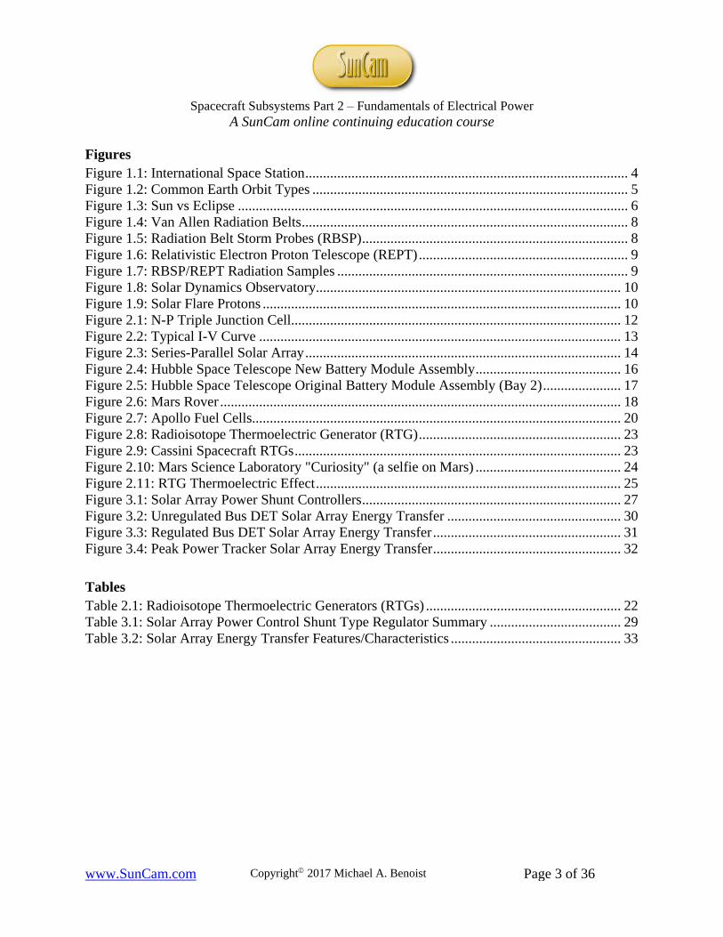
Figures Figure 1.1: International Space Station ........................................................................................... 4 Figure 1.2: Common Earth Orbit Types ......................................................................................... 5 Figure 1.3: Sun vs Eclipse .............................................................................................................. 6 Figure 1.4: Van Allen Radiation Belts ............................................................................................ 8 Figure 1.5: Radiation Belt Storm Probes (RBSP) ........................................................................... 8 Figure 1.6: Relativistic Electron Proton Telescope (REPT) ........................................................... 9 Figure 1.7: RBSP/REPT Radiation Samples .................................................................................. 9 Figure 1.8: Solar Dynamics Observatory ...................................................................................... 10 Figure 1.9: Solar Flare Protons ..................................................................................................... 10 Figure 2.1: N-P Triple Junction Cell............................................................................................. 12 Figure 2.2: Typical I-V Curve ...................................................................................................... 13 Figure 2.3: Series-Parallel Solar Array ......................................................................................... 14 Figure 2.4: Hubble Space Telescope New Battery Module Assembly ......................................... 16 Figure 2.5: Hubble Space Telescope Original Battery Module Assembly (Bay 2) ...................... 17 Figure 2.6: Mars Rover ................................................................................................................. 18 Figure 2.7: Apollo Fuel Cells........................................................................................................ 20 Figure 2.8: Radioisotope Thermoelectric Generator (RTG) ......................................................... 23 Figure 2.9: Cassini Spacecraft RTGs ............................................................................................ 23 Figure 2.10: Mars Science Laboratory "Curiosity" (a selfie on Mars) ......................................... 24 Figure 2.11: RTG Thermoelectric Effect ...................................................................................... 25 Figure 3.1: Solar Array Power Shunt Controllers ......................................................................... 27 Figure 3.2: Unregulated Bus DET Solar Array Energy Transfer ................................................. 30 Figure 3.3: Regulated Bus DET Solar Array Energy Transfer ..................................................... 31 Figure 3.4: Peak Power Tracker Solar Array Energy Transfer ..................................................... 32 Tables Table 2.1: Radioisotope Thermoelectric Generators (RTGs) ....................................................... 22 Table 3.1: Solar Array Power Control Shunt Type Regulator Summary ..................................... 29 Table 3.2: Solar Array Energy Transfer Features/Characteristics ................................................ 33

Spacecraft Subsystems Part 2 ‒ Fundamentals of Electrical Power
A SunCam online continuing education course
www.SunCam.com Copyright 2017 Michael A. Benoist Page 4 of 36
1. Introduction Spacecraft are man-made machines capable of operating in space. An orbiting spacecraft is normally referred to as a satellite, although it is manmade (aka "artificial") as opposed to a natural satellite like our moon [ref. 1]. Electrical Power in the context of this course refers to the generation and delivery of electricity to supply power to the spacecraft loads. This is the same concept as electricity is provided to your home to power the loads you plug into your electrical outlets. A spacecraft is typically subdivided into two major parts, the payload and the bus. Where the mission can be defined as the purpose of the spacecraft and is usually identified as the payload part of the spacecraft (e.g. scientific instruments, communications). The electrical power subsystem and other subsystems (e.g. attitude control, thermal control, structures) are part of the bus. With the primary goal of achieving a successful mission, most bus design constraints focus on maximizing the effectiveness of its payload [ref. 1]. For higher reliability, a spacecraft will have redundancy for all critical systems (e.g. an A and a B electrical power bus). The International Space Station's electrical power subsystem has solar panels with 262,400 solar cells in total to generate 84-120 kW; enough electricity to power over 40 homes (see FIGURE 1.1).
Figure 1.1: International Space Station Final Configuration (Fall, 2011) [Reprint from source: NASA @ nasa.gov]
Spacecraft Subsystems Part 2 ‒ Fundamentals of Electrical Power
A SunCam online continuing education course
www.SunCam.com Copyright 2017 Michael A. Benoist Page 5 of 36
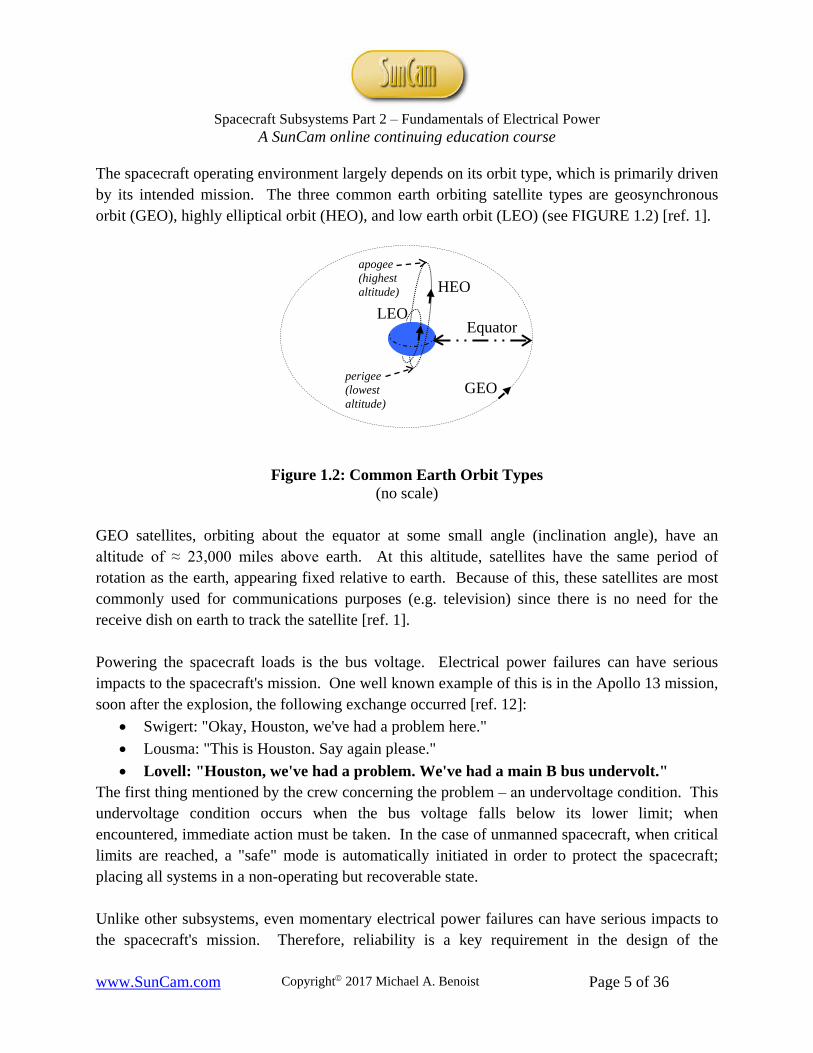
The spacecraft operating environment largely depends on its orbit type, which is primarily driven by its intended mission. The three common earth orbiting satellite types are geosynchronous orbit (GEO), highly elliptical orbit (HEO), and low earth orbit (LEO) (see FIGURE 1.2) [ref. 1].
Figure 1.2: Common Earth Orbit Types (no scale)
GEO satellites, orbiting about the equator at some small angle (inclination angle), have an altitude of ≈ 23,000 miles above earth. At this altitude, satellites have the same period of rotation as the earth, appearing fixed relative to earth. Because of this, these satellites are most commonly used for communications purposes (e.g. television) since there is no need for the receive dish on earth to track the satellite [ref. 1]. Powering the spacecraft loads is the bus voltage. Electrical power failures can have serious impacts to the spacecraft's mission. One well known example of this is in the Apollo 13 mission, soon after the explosion, the following exchange occurred [ref. 12]:
• Swigert: "Okay, Houston, we've had a problem here." • Lousma: "This is Houston. Say again please." • Lovell: "Houston, we've had a problem. We've had a main B bus undervolt."
The first thing mentioned by the crew concerning the problem ‒ an undervoltage condition. This undervoltage condition occurs when the bus voltage falls below its lower limit; when encountered, immediate action must be taken. In the case of unmanned spacecraft, when critical limits are reached, a "safe" mode is automatically initiated in order to protect the spacecraft; placing all systems in a non-operating but recoverable state. Unlike other subsystems, even momentary electrical power failures can have serious impacts to the spacecraft's mission. Therefore, reliability is a key requirement in the design of the
LEO
GEO perigee (lowest altitude)
Equator
HEO apogee (highest altitude)

Spacecraft Subsystems Part 2 ‒ Fundamentals of Electrical Power
A SunCam online continuing education course
www.SunCam.com Copyright 2017 Michael A. Benoist Page 6 of 36
spacecraft electrical power subsystem. Also, unlike other subsystems, other subsystems compete for its resource ‒ electrical power. One of these subsystems, the payload, usually gets priority over the bus subsystems (e.g. attitude control). The payload subsystem can be thought of as the subsystem "paying" for the spacecraft's mission. To achieve high reliability, the designer must understand the typically harsh space environment the spacecraft must "live". Specifically for the electrical power subsystem engineer, how often will the sun be present and what/where are the environmental hazards.
Sun Presence To the electrical power subsystem, the presence or absence of the sun is critical to know in advance of any design. Each of the orbital types have a cyclical characteristic where the spacecraft goes from light (i.e. the sun is present) to dark (i.e. cannot "see" the sun). Sometimes, the spacecraft may be in sunlight or darkness for extended periods of time; worst cases are known as 100% sun or minimum sun respectively. Since many satellites are solar-battery powered, how often you can rely on the sun as a power source is key to mission success. These satellites use the sun to power the spacecraft during the part of the orbit when the sun is present and use their batteries to supply power during eclipse periods (see FIGURE 1.3). Thus, orbital period and percent (%) sun will greatly influence the design of the electrical power subsystem. Orbital period refers to how long it takes the spacecraft to complete one earth orbit (e.g. ≈ 24hrs for GEO). Percent sun refers to the amount of sun present during each orbit. For example, in 100% sun, the spacecraft is "seeing" the sun the entire duration of each orbit; where the sun vector is normal (orthogonal) to the orbital plane (see Sat #2 in FIGURE 1.3). These orbital characteristics will determine the number of battery charge/discharge cycles needed and consequently its battery life; a major limiting factor in the expected mission life of a solar-battery powered spacecraft.
Figure 1.3: Sun vs Eclipse (no scale)
Eclipse Sunlight Sat #1 (in minimum sun)
Sat #2 (in 100% sun)

Spacecraft Subsystems Part 2 ‒ Fundamentals of Electrical Power
A SunCam online continuing education course
www.SunCam.com Copyright 2017 Michael A. Benoist Page 7 of 36
Minimum sun refers to the least amount of time per orbit the spacecraft will "see" sunlight. It is important to know what the minimum sun will be in order to calculate the worst case recharge and discharge times for the battery: minimum recharge and maximum discharge. These battery recharge/discharge times are necessary in order to establish the requirements for solar array and battery size as well as solar array geometry. For most orbits, the spacecraft will experience minimum sun biannually; when the sun vector is parallel with the orbital plane (see Sat #1 in FIGURE 1.3).
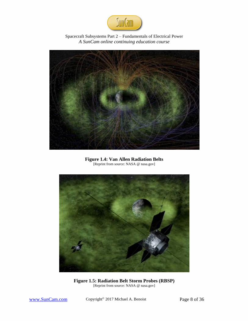
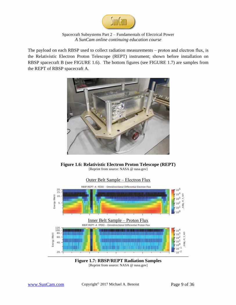
Environmental Hazards The environment where spacecraft can operate is very hostile in general. Specifically for the electrical power subsystem, protons and electrons in the earth's magnetosphere and solar flare protons outside of the earth's magnetosphere are most problematic for solar cells. FIGURE 1.4 (next page) is a screen capture from a graphic animation of the Van Allen radiation belts showing the earth's magnetic field lines and the radiation belts' surrounding the earth in the form of two donuts. Their locations above the earth ranges from about 1,000-8,000 miles for the inner belt and 12,000-25,000 miles for the outer belt. Within the earth's magnetosphere, protons in the inner belt of the Van Allen belts are the most destructive to solar cells. It is primarily for this reason, most solar powered spacecraft are in LEO (<1,000 miles) or GEO (≈ 23,000 miles) orbits. It is for this same reason, all solar cells used in space are n-p junction type; because they are less likely to sustain damage from charged particle radiation (protons and electrons) than p-n type. If this destructive altitude is unavoidable due to mission requirements, the HEO type can be utilized. In HEO, the satellite's dwell time at perigee is much shorter than at apogee because the satellite accelerates as it approaches earth (towards perigee); therefore, the time spent in this damaging region is limited. To further explore the Van Allen radiation belts, two Radiation Belt Storm Probes (RBSPs) are shown in this artist's rendering (FIGURE 1.5, next page). Their mission (aka Van Allen Probe-A and Van Allen Probe-B) is to collect radiation measurements while orbiting through the radiation belts. These probes are radiation hardened for this mission; in HEO orbit, with an apogee and perigee of about 23,000 and 373 miles respectively.
Spacecraft Subsystems Part 2 ‒ Fundamentals of Electrical Power
A SunCam online continuing education course
www.SunCam.com Copyright 2017 Michael A. Benoist Page 8 of 36
Figure 1.4: Van Allen Radiation Belts [Reprint from source: NASA @ nasa.gov]
Figure 1.5: Radiation Belt Storm Probes (RBSP) [Reprint from source: NASA @ nasa.gov]
Spacecraft Subsystems Part 2 ‒ Fundamentals of Electrical Power
A SunCam online continuing education course
www.SunCam.com Copyright 2017 Michael A. Benoist Page 9 of 36
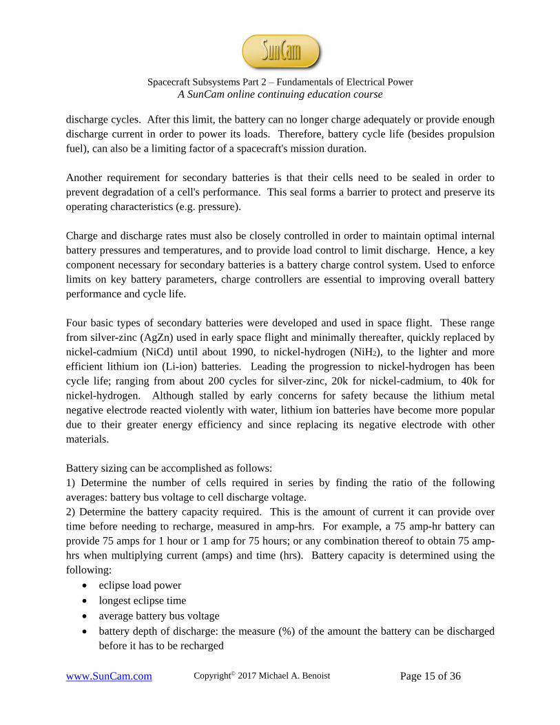
The payload on each RBSP used to collect radiation measurements ‒ proton and electron flux, is the Relativistic Electron Proton Telescope (REPT) instrument; shown before installation on RBSP spacecraft B (see FIGURE 1.6). The bottom figures (see FIGURE 1.7) are samples from the REPT of RBSP spacecraft A.
Figure 1.6: Relativistic Electron Proton Telescope (REPT) [Reprint from source: NASA @ nasa.gov]
Outer Belt Sample ‒ Electron Flux
Inner Belt Sample ‒ Proton Flux
Figure 1.7: RBSP/REPT Radiation Samples
[Reprint from source: NASA @ nasa.gov]

Spacecraft Subsystems Part 2 ‒ Fundamentals of Electrical Power
A SunCam online continuing education course
www.SunCam.com Copyright 2017 Michael A. Benoist Page 10 of 36
Above the earth's magnetosphere, solar flare protons are most destructive to solar arrays. These protons peak when random solar activity is near its highest; causing problems for satellites to GEO altitudes as well as interplanetary space missions. Solar flare protons are released by intense bursts of radiation. One such burst was caught on April 17, 2016 by NASA’s Solar Dynamics Observatory spacecraft ‒ see artist's depiction of the spacecraft in FIGURE 1.8 and the solar flare burst in right side of FIGURE 1.9. Although random, computer modeling can be used to estimate solar flare fluences (particle streams).
Figure 1.8: Solar Dynamics Observatory [Reprint from source: NASA @ nasa.gov]
Figure 1.9: Solar Flare Protons [Reprint from source: NASA @ nasa.gov]

Spacecraft Subsystems Part 2 ‒ Fundamentals of Electrical Power
A SunCam online continuing education course
www.SunCam.com Copyright 2017 Michael A. Benoist Page 11 of 36
2. Power Sources This section describes various power source options for converting their energy into electrical power for spacecraft. The basic conversion types are solar, electrochemical, and nuclear. Each of these types will be represented by describing five different power sources: solar arrays, secondary batteries, primary batteries, fuel cells, and radioisotope thermoelectric generators (RTGs). The type selected largely depends on the mission requirements.
Solar Arrays Since solar panels only generate power when illuminated by the sun, knowledge of the angle between the sun vector and the solar panel is essential at all times. This is because solar illumination only occurs when this angle is between 0° and 90°; where near zero provides minimal illumination and ninety provides maximum solar cell illumination. Therefore, in design and/or operation, you must know where the sun is with respect to the spacecraft over its entire mission lifetime. With this knowledge, maximum power generation efficiency can be realized by keeping the solar arrays pointing towards the sun. Solar array sun pointing is achieved by using spacecraft orientation (attitude) maneuvers or employing solar array tracking mechanisms, or both. Sometimes a shadow study is also necessary if there are concerns the spacecraft body and/or an appendage may block part of a solar panel from the sun. Five types of solar cells have been used in space flight. These range from silicon (single junction) used from initial flight to about 1990, to the more efficient triple junction cells. The other three (high-efficiency silicon, single and dual junction gallium arsenide) have been used as more of a transition between the silicon and triple junction types. As eluded to, driving this progression has been cell efficiency, from about 14% for silicon to about 30% for triple junction types. The dual junction gallium arsenide cell was made by adding a GaInP (gallium indium phosphide) junction on top of the GaAs (gallium arsenide) junction on the inactive Ge (germanium) substrate. Triple junction cells rapidly followed by activating the germanium substrate to add the third junction. Each of the three cell junctions essentially behaves as an electrical diode connected in series (see FIGURE 2.1).

Spacecraft Subsystems Part 2 ‒ Fundamentals of Electrical Power
A SunCam online continuing education course
www.SunCam.com Copyright 2017 Michael A. Benoist Page 12 of 36
Structure Electrical Equivalent
Figure 2.1: N-P Triple Junction Cell
These three junctions together provide two key improvements: higher power and efficiency. Since they are stacked and connected in series to operate as semiconductors, their voltages add; providing much greater voltage and power than their predecessors. Also, the three different energy band gaps provided by each junction allows the cell to convert a broader wavelength of the solar spectrum, from 350 to 1550 nanometers, with: GaInP @ 350-700, GaAs @ 700-900, and Ge @ 900-1550; thus, increasing the efficiency of the cell's area. Besides the efficiency at maximum power, efficiencymp (%), the key performance parameters provided by the solar cell manufacturer for triple junction solar cells include the following: Symbol (Units): Solar Cell Parameter Definition
• Voc (V): open circuit voltage • Isc (mA/cm2): short circuit current • Vmp (V): voltage at maximum power • Imp (mA/cm2): current at maximum power
These parameters are typically plotted on an I-V curve at standard measurement conditions. The solar cell's maximum power (Pmp) output can be determined by plotting the coordinates of (Vmp, Imp) provided by the manufacturer. Note, this point is also the efficiency at maximum power, efficiencymp (%). Using this point, the area of maximum power can be drawn on the graph (aka fill factor) (see FIGURE 2.2).
+
- +
-
- +
Ge Base/substrate (P)
Ge Emitter (N+)
GaInP Base (P)
GaInP Emitter (N+)
GaAs Base (P)
GaAs Emitter (N+)

Spacecraft Subsystems Part 2 ‒ Fundamentals of Electrical Power
A SunCam online continuing education course
www.SunCam.com Copyright 2017 Michael A. Benoist Page 13 of 36
Figure 2.2: Typical I-V Curve
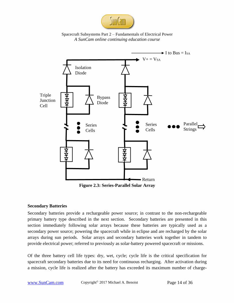
Temperature coefficients and radiation performance values are also provided by solar cell manufacturers at each of the performance parameters over multiple test irradiances. The radiation performance values are important because of charged particle radiation (e.g. protons) in the space environment contaminates the solar cell's structure and subsequently degrades its spectral response and I-V curve over the life of its mission. In addition to radiation concerns, temperature coefficients are provided because efficiency decreases with increasing temperature. Therefore, cell operating temperatures are kept as low as possible by adding coatings to the panel for thermal control. Solar arrays are typically constructed in a series-parallel configuration; where the cells are in series to create a string, and the strings are in parallel (see FIGURE 2.3). The electrical output characteristics are as follows:
(Key: "SA" = solar array and "c" = cell)
• PowerSA (PSA) = Pc multiplied by the number of cells in solar array • CurrentSA (ISA) = Ic multiplied by the number of parallel strings • VoltageSA (VSA) = Vc multiplied by the number of series connected cells per string
The bypass diodes protect each cell from reverse bias damage commonly due to shadowing of the cell and the isolation diodes protect each series string from arcing due to electrostatic discharge.
Area = Maximum Power
Pmp
Spacecraft Subsystems Part 2 ‒ Fundamentals of Electrical Power
A SunCam online continuing education course
www.SunCam.com Copyright 2017 Michael A. Benoist Page 14 of 36
Figure 2.3: Series-Parallel Solar Array
Secondary Batteries Secondary batteries provide a rechargeable power source; in contrast to the non-rechargeable primary battery type described in the next section. Secondary batteries are presented in this section immediately following solar arrays because these batteries are typically used as a secondary power source; powering the spacecraft while in eclipse and are recharged by the solar arrays during sun periods. Solar arrays and secondary batteries work together in tandem to provide electrical power; referred to previously as solar-battery powered spacecraft or missions. Of the three battery cell life types: dry, wet, cycle; cycle life is the critical specification for spacecraft secondary batteries due to its need for continuous recharging. After activation during a mission, cycle life is realized after the battery has exceeded its maximum number of charge-
V+ = VSA
Return
Isolation Diode
Bypass Diode
Triple Junction Cell
I to Bus = ISA
Parallel Strings
Series Cells
Series Cells
Spacecraft Subsystems Part 2 ‒ Fundamentals of Electrical Power
A SunCam online continuing education course
www.SunCam.com Copyright 2017 Michael A. Benoist Page 15 of 36
discharge cycles. After this limit, the battery can no longer charge adequately or provide enough discharge current in order to power its loads. Therefore, battery cycle life (besides propulsion fuel), can also be a limiting factor of a spacecraft's mission duration. Another requirement for secondary batteries is that their cells need to be sealed in order to prevent degradation of a cell's performance. This seal forms a barrier to protect and preserve its operating characteristics (e.g. pressure). Charge and discharge rates must also be closely controlled in order to maintain optimal internal battery pressures and temperatures, and to provide load control to limit discharge. Hence, a key component necessary for secondary batteries is a battery charge control system. Used to enforce limits on key battery parameters, charge controllers are essential to improving overall battery performance and cycle life. Four basic types of secondary batteries were developed and used in space flight. These range from silver-zinc (AgZn) used in early space flight and minimally thereafter, quickly replaced by nickel-cadmium (NiCd) until about 1990, to nickel-hydrogen (NiH2), to the lighter and more efficient lithium ion (Li-ion) batteries. Leading the progression to nickel-hydrogen has been cycle life; ranging from about 200 cycles for silver-zinc, 20k for nickel-cadmium, to 40k for nickel-hydrogen. Although stalled by early concerns for safety because the lithium metal negative electrode reacted violently with water, lithium ion batteries have become more popular due to their greater energy efficiency and since replacing its negative electrode with other materials. Battery sizing can be accomplished as follows: 1) Determine the number of cells required in series by finding the ratio of the following averages: battery bus voltage to cell discharge voltage. 2) Determine the battery capacity required. This is the amount of current it can provide over time before needing to recharge, measured in amp-hrs. For example, a 75 amp-hr battery can provide 75 amps for 1 hour or 1 amp for 75 hours; or any combination thereof to obtain 75 amp-hrs when multiplying current (amps) and time (hrs). Battery capacity is determined using the following:
• eclipse load power • longest eclipse time • average battery bus voltage • battery depth of discharge: the measure (%) of the amount the battery can be discharged
before it has to be recharged

Spacecraft Subsystems Part 2 ‒ Fundamentals of Electrical Power
A SunCam online continuing education course
www.SunCam.com Copyright 2017 Michael A. Benoist Page 16 of 36
During NASA's final space shuttle mission to service the Hubble Space Telescope (HST) in May of 2009, the nickel-hydrogen batteries were replaced in order to help extend Hubble's mission life. FIGURE 2.4 (below) shows one of the two battery module assemblies (with cover removed) and one of the original assemblies installed (see FIGURE 2.5, next page). Each of the HST's 6 batteries (3 per battery module assembly) contains 22 individual cells connected in series. Each battery provides 75 amp-hrs for a total of 450 amp-hrs of capacity.
Figure 2.4: Hubble Space Telescope New Battery Module Assembly
[Reprint from source: NASA @ nasa.gov]

Spacecraft Subsystems Part 2 ‒ Fundamentals of Electrical Power
A SunCam online continuing education course
www.SunCam.com Copyright 2017 Michael A. Benoist Page 17 of 36
Figure 2.5: Hubble Space Telescope Original Battery Module Assembly (Bay 2) [Reprint from source: NASA @ nasa.gov]
Primary Batteries Primary batteries are not a rechargeable power source; in contrast to the rechargeable secondary battery type described in the previous section. Therefore, primary batteries do not require another power source (e.g. solar arrays) in order to recharge. These batteries are capable of providing the only power to the load and can be used as the primary power source for short-term spacecraft missions or other applications (e.g. exploration vehicles) with low power requirements.

Spacecraft Subsystems Part 2 ‒ Fundamentals of Electrical Power
A SunCam online continuing education course
www.SunCam.com Copyright 2017 Michael A. Benoist Page 18 of 36
Primary battery space flight candidates range from liquid cathode types: silver-zinc (AgZn) used in initial flight, lithium-sulfur dioxide (Li-SO2), lithium-thionyl chloride (Li-SOCl2), and lithium-oxyhalides; to the less hazardous solid cathode lithium-polycarbon monofluoride (Li-CFx) batteries. Unlike the previously described secondary batteries, these types still remain viable choices for most spacecraft applications; and unlike the lithium metal used initially for secondary batteries, the lithium negative electrode is made less reactive by the electrolyte in the primary battery chemistries. A major advantage of lithium cells is that since they are sealed; there is minimal risk of external gas venting. In contrast, silver-zinc type cells need to vent gas during discharge. This venting could contaminate spacecraft sensitive components potentially interfering with payload experiments. Recall, this is unlike the reason for secondary batteries, where all are required to be sealed to preserve their operating characteristics. One unique application of primary batteries is for the exploration of mars; the Pathfinder mission in 1997 landed the rover Sojourner (see FIGURE 2.6). The rover, shown below (left), about the size of a milk crate, uses three lithium-thionyl chloride batteries connected in series below (right). Even though the rover had a solar panel (note, the solar array on top of rover), it was not used to recharge the batteries. The batteries were used minimally, when conducting night time experiments or when there was insufficient sun. In addition, in the event either power source failed (solar arrays or batteries), individually they could provide enough power to complete the primary mission. Rover Sojourner Rover Primary Batteries
Figure 2.6: Mars Rover
[Reprint from source: NASA @ nasa.gov]

Spacecraft Subsystems Part 2 ‒ Fundamentals of Electrical Power
A SunCam online continuing education course
www.SunCam.com Copyright 2017 Michael A. Benoist Page 19 of 36
Selection of the optimum primary battery largely depends on the system requirements. Some of the major battery characteristics to be considered are:
• long shelf life: dry life and wet life (after electrolyte is added) • high energy density: energy per unit weight and energy per unit volume • non-hazardous attributes (e.g. gas venting) • wide operating temperature range
Shelf life is normally a key concern because satellite launch schedules are prone to slipping, thus amplifying the importance that a battery has a longer shelf life. Also, it should be no surprise if a satellite "lives" longer than its expected mission life since battery rated capacities (amp-hr) are typically conservative; meaning their actual capacity is greater than rated. This is because rated capacities are provided by the battery manufacturer, who must meet the spacecraft builder's expectations and more importantly their requirements.
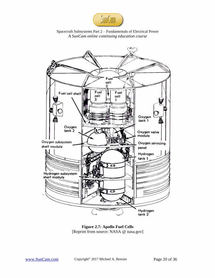
Fuel Cells Another electrochemical device (beside batteries) used to generate electricity is the fuel cell. These are driven by chemical reactions from external fuel (e.g. hydrogen) and oxidizers (e.g. oxygen) delivered to the cell when needed. Although many different fuels and oxidizers can be used, only hydrogen and oxygen respectively have been typically used in space; as in the Apollo mission used to activate 3 fuel cells in the service module (see FIGURE 2.7, next page). Because they require both oxidizer and fuel, fuel cells are only considered for short term space applications typically from a few minutes to a month (e.g. NASA's space shuttle and Apollo missions). Note: In the Apollo 13 mission, oxygen tank 2 exploded; but this also caused oxygen tank 1 or its components to fail.
Spacecraft Subsystems Part 2 ‒ Fundamentals of Electrical Power
A SunCam online continuing education course
www.SunCam.com Copyright 2017 Michael A. Benoist Page 20 of 36
Figure 2.7: Apollo Fuel Cells [Reprint from source: NASA @ nasa.gov]

Spacecraft Subsystems Part 2 ‒ Fundamentals of Electrical Power
A SunCam online continuing education course
www.SunCam.com Copyright 2017 Michael A. Benoist Page 21 of 36
Finally, it is worth mentioning, designing systems to operate in zero-gravity is very complex when compared to systems on earth. This zero-gravity "problem" creates design challenges for many subsystems. An example of this was for the space shuttle's multimillion dollar toilet. In order to justify this extreme cost for a toilet to congress; NASA explained, try using your toilet if it were on the ceiling [ref. 7]. For the fuel cell, its zero-gravity problem is how to remove water from the cell. This water, a byproduct of the fuel cell's chemical reaction, can be removed by capillary action. Capillary action uses surface tension between the water (liquid) and a tube (solid) to move the water to a reservoir where it can then be used as potable water.
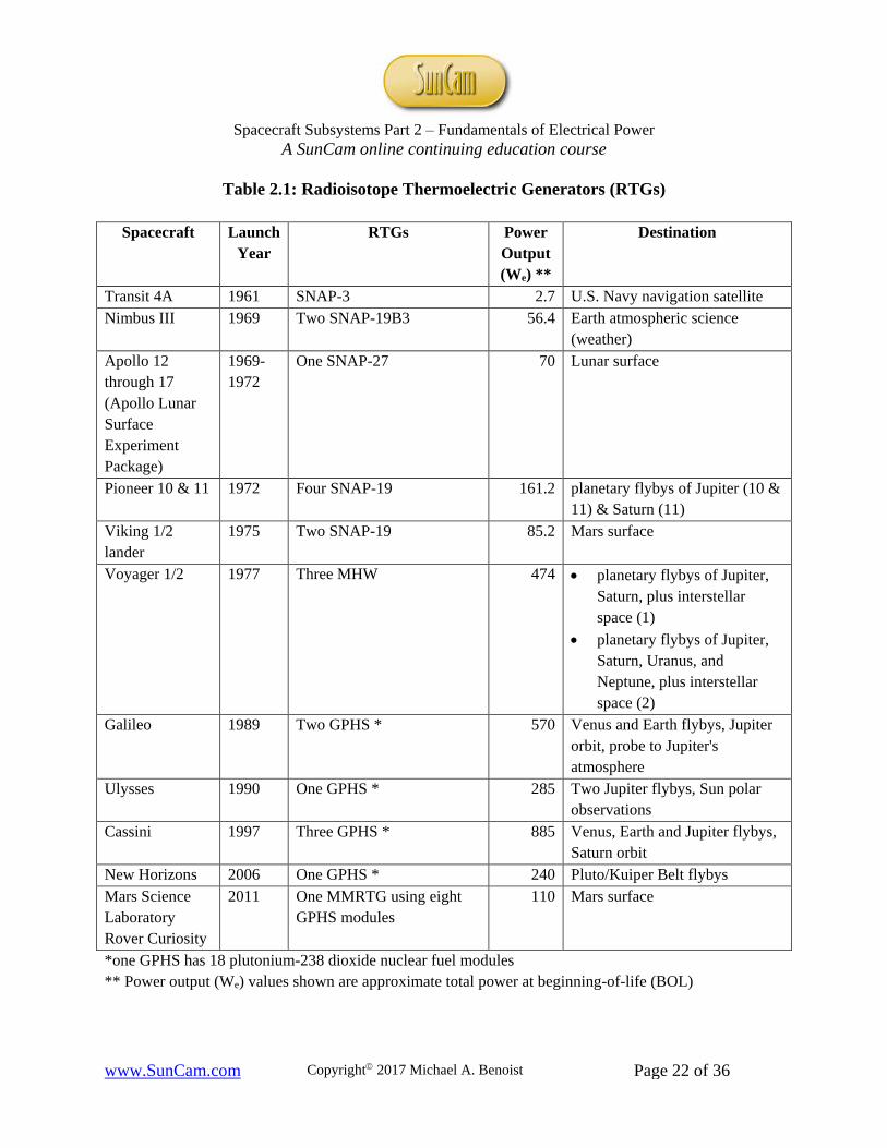
Radioisotope Thermoelectric Generators Radioisotope thermoelectric generators (RTGs) offer another power source choice when others are not practical. Radioisotope refers to the nuclear fuel used to produce heat and thermoelectric (described later) refers to the process used to generate electricity. RTGs are reliable, lightweight, and provide continuous power; both electrical (We) and thermal (Wt). Since RTGs also provide continuous thermal power, the spacecraft requires continuous heat shunting of Wt. Also, because their power degrades over time, the electrical power subsystem must be designed to their end-of-life (EOL) specifications of We. Since RTGs are extremely hazardous, their nuclear fuel modules are designed to be recoverable intact. It is for this primary safety reason, use of RTGs are limited and are only considered when other power sources (e.g. solar arrays, batteries) are impractical for the mission. Four basic types of RTGs were developed and used in space flight. These range from systems for nuclear auxiliary power (SNAP) in 1961, multi-hundred watt (MHW), general purpose heat source (GPHS), to multi-mission radioisotope thermoelectric generator (MMRTG) in 2012. Leading the drive in progression for RTGs has primarily been the need for higher electrical power output, We (see TABLE 2.1).
Spacecraft Subsystems Part 2 ‒ Fundamentals of Electrical Power
A SunCam online continuing education course
www.SunCam.com Copyright 2017 Michael A. Benoist Page 22 of 36
Table 2.1: Radioisotope Thermoelectric Generators (RTGs)
Spacecraft Launch Year
RTGs Power Output (We) **
Destination
Transit 4A 1961 SNAP-3 2.7 U.S. Navy navigation satellite Nimbus III 1969 Two SNAP-19B3 56.4 Earth atmospheric science
(weather) Apollo 12 through 17 (Apollo Lunar Surface Experiment Package)
1969-1972
One SNAP-27 70 Lunar surface
Pioneer 10 & 11 1972 Four SNAP-19 161.2 planetary flybys of Jupiter (10 & 11) & Saturn (11)
Viking 1/2 lander
1975 Two SNAP-19 85.2 Mars surface
Voyager 1/2 1977 Three MHW 474 • planetary flybys of Jupiter, Saturn, plus interstellar space (1)
• planetary flybys of Jupiter, Saturn, Uranus, and Neptune, plus interstellar space (2)
Galileo 1989 Two GPHS * 570 Venus and Earth flybys, Jupiter orbit, probe to Jupiter's atmosphere
Ulysses 1990 One GPHS * 285 Two Jupiter flybys, Sun polar observations
Cassini 1997 Three GPHS * 885 Venus, Earth and Jupiter flybys, Saturn orbit
New Horizons 2006 One GPHS * 240 Pluto/Kuiper Belt flybys Mars Science Laboratory Rover Curiosity
2011 One MMRTG using eight GPHS modules
110 Mars surface
*one GPHS has 18 plutonium-238 dioxide nuclear fuel modules ** Power output (We) values shown are approximate total power at beginning-of-life (BOL)

Spacecraft Subsystems Part 2 ‒ Fundamentals of Electrical Power
A SunCam online continuing education course
www.SunCam.com Copyright 2017 Michael A. Benoist Page 23 of 36
Launched in 1997, Cassini is the first spacecraft to orbit saturn. The figure below (FIGURE 2.8), is a Cassini RTG before spacecraft integration. The 3 RTGs, orthogonal to one another, can be seen below in this artist's depiction of Cassini orbiting saturn (see FIGURE 2.9).
Figure 2.8: Radioisotope Thermoelectric Generator (RTG)
[Reprint from source: NASA @ nasa.gov]
Figure 2.9: Cassini Spacecraft RTGs
[Reprint from source: NASA @ nasa.gov]
RTG

Spacecraft Subsystems Part 2 ‒ Fundamentals of Electrical Power
A SunCam online continuing education course
www.SunCam.com Copyright 2017 Michael A. Benoist Page 24 of 36
Powered by one MMRTG, the rover Curiosity created this selfie (see FIGURE 2.10). This high resolution image, taken in 2012, was created by capturing multiple images using the rover's camera attached to its robotic arm; then combining each of them together like a puzzle to form one image.
Figure 2.10: Mars Science Laboratory "Curiosity" (a selfie on Mars) [Reprint from source: NASA @ nasa.gov]
RTGs contain semiconductor elements electrically connected in series and physically configured in parallel. The heat is generated by a nuclear fuel source, typically plutonium-238 dioxide. These elements are physically configured in parallel so the heat flows evenly through each element. The series elements, known as N and P legs, contain "n" and "p" doped semiconductor elements respectively. The combination of this material difference (n vs. p) and the temperature

Spacecraft Subsystems Part 2 ‒ Fundamentals of Electrical Power
A SunCam online continuing education course
www.SunCam.com Copyright 2017 Michael A. Benoist Page 25 of 36
difference produces a proportional electrical potential (voltage) ‒ a process called thermoelectric (aka Seebeck) effect; hence, creating a thermocouple device. FIGURE 2.11 below describes this effect using six semiconductor elements ‒ three thermocouples.
Figure 2.11: RTG Thermoelectric Effect Like solar cells, the thermocouples are connected in series as a string so their voltages add. And like solar arrays, final RTG configuration will also contain multiple strings in parallel in order to create the required voltage and therefore electrical power for the mission. Another important design consideration for heat shunting is impedance matching. The shunt impedance should match the source and the load impedances. This is the same concept as for maximum power transfer in AC/DC electrical theory; occurring when the load and source resistances are equal. This impedance matching in the RTG electrical subsystem design will help prevent the following:
• performance degradation • source overheating • reduction of its expected mission life
+ N -
- P +
+ N -
- P +
+ N -
- P +
Heat Sink (e.g. shunt radiator) = COLD
Heat Source (e.g. plutonium-238 dioxide) = HOT Insulating Material
Connection Straps
+ - heat flow
Load
Thermocouple

Spacecraft Subsystems Part 2 ‒ Fundamentals of Electrical Power
A SunCam online continuing education course
www.SunCam.com Copyright 2017 Michael A. Benoist Page 26 of 36
3. Power Regulation Since solar arrays are widely used as the primary electrical power source for spacecraft, this section describes the fundamentals to regulate the solar array power:
• by controlling the amount of power generated by the solar arrays • deciding the best method to be used for solar array energy transfer to the spacecraft loads
Another important consideration in the design of the electrical power subsystem is the employment of power converters, used to increase or decrease a DC input voltage. The two main types of DC-DC converters are named after their function ‒ buck and boost. These converters are generally used to either step down (buck) or step up (boost) voltages during battery charge or discharge respectively. DC-DC converters are also used in peak power tracker type solar array energy transfer systems (to be explained later) and connected directly to individual loads if a load requires a different voltage than the bus voltage supplies.
Solar Array Power Control There are two basic ways of controlling the amount of power generated by the solar arrays: series or shunt regulation. Because the general concepts (e.g. sequential, digital) for shunt can also be applied to series, we will only describe shunt regulators in this section. For series regulation, the components are on the bus instead of off the bus as in shunt. Shunting effectively turns off, on, or adjusts the current delivered to the bus by each parallel solar cell string in order to regulate the spacecraft bus current. This shunt regulation is determined by the amount of current required for the spacecraft loads and battery charging. When too much solar array current is generated, the excess energy is thermally dissipated by either the solar arrays or shunt circuit components. Typically, an undesired effect of shunting is the excess heat produced. This can create challenges for thermal control within the spacecraft body (i.e. how do we remove the heat to minimize impacts to other spacecraft components?). Except for the full linear shunt, all other shunt types explained in this section were created in order to mitigate this problem.

Spacecraft Subsystems Part 2 ‒ Fundamentals of Electrical Power
A SunCam online continuing education course
www.SunCam.com Copyright 2017 Michael A. Benoist Page 27 of 36
Using the figure from the previous solar arrays section, two different types of shunt regulators are added: full linear and digital (see FIGURE 3.1). These two types are commonly utilized together, the digital shunt to provide coarse control and the full linear shunt to provide fine (more precise) control. If you visualize this figure (below) without the Tsw legs and digital sequencer, you have a full linear shunt. Using this shunt type, each transistor/resistor (TQ/Rsh) shunt leg can be configured across each series solar array string or across multiple strings; where each transistor is operating in the linear range (unsaturated) as represented by Q (quiescent). Bus current Ib represents the current demand by the spacecraft load and battery, and Ish is the shunted excess current. Because total shunted power can be high, as dissipated by both the transistor and resistor, this type is generally used in spacecraft low power applications.
Figure 3.1: Solar Array Power Shunt Controllers If you visualize this figure (above) without the TQ leg and linear controller, you have a digital shunt. Low shunt power is generated using this type since all shunt transistors are ON (shorted, saturated) or OFF (open); essentially functioning as a switch (TSW) with no current limiting resistors needed.
Return
Linear Controller Digital Sequencer
Control Signal
V+
Rsh
Ib
Is
Ia Ia
TQ TSW TSW
Spacecraft Subsystems Part 2 ‒ Fundamentals of Electrical Power
A SunCam online continuing education course
www.SunCam.com Copyright 2017 Michael A. Benoist Page 28 of 36
Another type, the partial linear shunt splits the solar array string into an upper (not shunted) section and lower (shunted) section by connecting the shunt circuit to the middle of the string instead of off the bus as in the full linear shunt. In addition, it has no current limiting resistor to help prevent damage to the transistor. Instead, quad redundant transistors are used to provide higher reliability. A fourth type, the sequential linear shunt is essentially a group of full or partial linear shunts connected to the same linear controller where only one transistor (TQ) is operating in the linear range. Each transistor is turned on sequentially to become TQ as needed. All shunt transistors before TQ are ON (shorted, saturated) and all shunts transistors after TQ are OFF (open), functioning as switches like in the digital shunt. This shunt technique minimizes total shunt transistor power by having only one shunt transistor operating through the linear range at any one time. Fifthly, the pulse width modulated (PWM) shunt is similar in configuration to the digital shunt. Instead of its transistor operating in the linear range as in the full/partial linear shunts, the PWM input to the transistor causes it to switch on/off over a high switching frequency by a controlled duty ratio. Because of this switching, no current limiting resistor is needed, further reducing shunt power. Hence, the PWM technique is useful in high power applications. Although this technique greatly reduces shunt power, switching current at high frequencies has an undesired consequence of inducing noise, which can adversely impact other spacecraft components in the form of electromagnetic interference (EMI). Lastly, the sequentially switched shunt regulator (aka S3R) is similar in configuration and operation to the sequential linear shunt, with the power reduction benefits of digital and PWM shunts (see summary TABLE 3.1, next page). All shunt transistors before TPWM are ON (shorted, saturated) and all shunts transistors after TPWM are OFF (open). Furthermore, compared to the PWM shunt, the negative impacts of EMI are mitigated since it has a single transistor operating in PWM mode.

Spacecraft Subsystems Part 2 ‒ Fundamentals of Electrical Power
A SunCam online continuing education course
www.SunCam.com Copyright 2017 Michael A. Benoist Page 29 of 36
The following table contains a summary of the features/characteristics of the six types of solar array power control shunt type regulators previously described in this section. All of these techniques can be used with either a regulated or an unregulated bus as will be described in the next section.
Table 3.1: Solar Array Power Control Shunt Type Regulator Summary
Solar Array Power Control Shunt Type Regulator
Application Shunt Power Reduction Technique Noise effect
Low Power
High Power
No Shunt
Resistor
Single Operating
Shunt Transistor
Transistor Switches
(On/Off) PWM EMI
Full Linear Partial Linear
Sequential Linear
Digital Pulse Width Modulated (PWM)
Sequentially Switched (aka S3R)

Spacecraft Subsystems Part 2 ‒ Fundamentals of Electrical Power
A SunCam online continuing education course
www.SunCam.com Copyright 2017 Michael A. Benoist Page 30 of 36
Solar Array Energy Transfer When employing solar arrays as the primary power source, you need to decide which method you will use to transfer the solar energy generated to the spacecraft loads. The optimum method chosen should be based on mission requirements (i.e. where are you going and how much work needs to be done?). A direct energy transfer (DET) system is one where the solar arrays have no active components in-line (series) with the load. Therefore, solar array electrical energy is transferred "directly" to the spacecraft loads. DET systems can be configured to regulate (control) the bus voltage. The following paragraphs will introduce three DET type systems, followed by a non-DET type ‒ the peak power tracker. Using the previous solar array shunt controller configuration; if we add the battery in parallel, we can show a simplified unregulated DET power system. In this power system, the maximum solar array voltage will be clamped to the battery voltage; thus, limiting the power supplied by the solar arrays (see FIGURE 3.2). Unique to this type is the absence of electronic processing elements on the bus or in between the bus and the battery. In other words, the solar array energy is directly fed to power the loads and recharge the battery. This DET configuration is useful when battery recharge time is short (e.g. LEO) or in very low power applications.
Figure 3.2: Unregulated Bus DET Solar Array Energy Transfer
Shunt Controller
Bus Voltage To Loads
Return
+
- Battery

Spacecraft Subsystems Part 2 ‒ Fundamentals of Electrical Power
A SunCam online continuing education course
www.SunCam.com Copyright 2017 Michael A. Benoist Page 31 of 36
Using the previous unregulated bus DET example; if we add three basic components, we can show a simplified regulated DET power system (see FIGURE 3.3). In this DET system, the power bus is continuously regulated by the battery charge/discharge elements; and the amount of solar array power generated is determined by the bus voltage controller. The bus voltage controller monitors the bus voltage (Vb), which is used to determine the control signals: e1 and e2. This DET configuration is useful in high power applications and provides flexibilities in electrical power subsystem design such as:
• DC-DC converters to spacecraft loads are simpler • battery design is not dependant on bus voltage
Figure 3.3: Regulated Bus DET Solar Array Energy Transfer A partially regulated DET (aka sun regulated) power system type is one where the battery charger is connected in between (or in series with) the battery and the bus. Note, this type of regulation is similar to the regulated bus type, but without a bus voltage controller or discharge regulator. Instead of the discharge regulator, a diode provides a current path to the spacecraft power bus then to the loads. In this power system, the bus is regulated during sun periods and unregulated during eclipse. When the load demand exceeds the available solar array power, the bus voltage drops to the battery voltage. This DET configuration is useful when battery recharge time is long (e.g. HEO, GEO), in low load power applications, and when low bus voltage is required. One disadvantage of using this type of regulation is its susceptibility to power system bus lock-up.
Bus Voltage (Vb)
Shunt Controller
To Loads
Return
+
- Battery
Battery Charger
Discharge Regulator
Bus Voltage Controller
Vb e1 e2
Spacecraft Subsystems Part 2 ‒ Fundamentals of Electrical Power
A SunCam online continuing education course
www.SunCam.com Copyright 2017 Michael A. Benoist Page 32 of 36
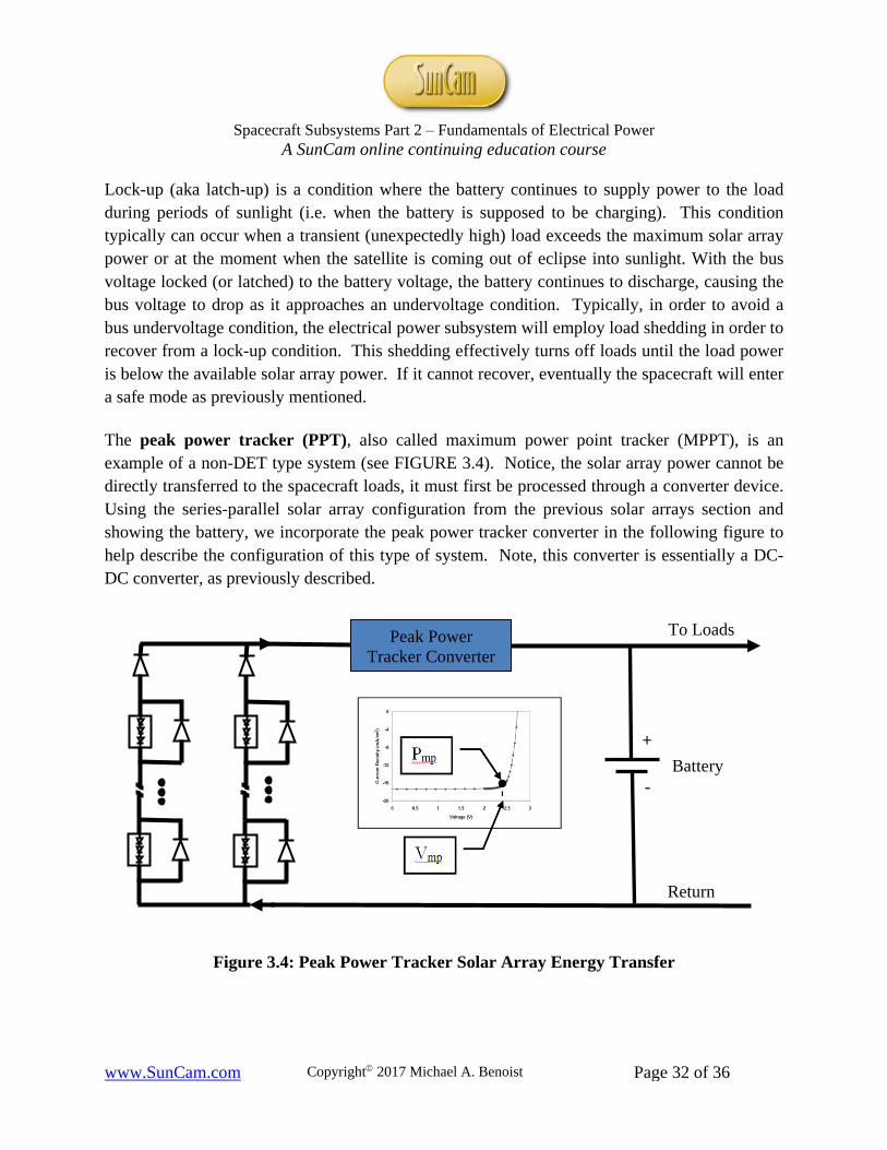
Lock-up (aka latch-up) is a condition where the battery continues to supply power to the load during periods of sunlight (i.e. when the battery is supposed to be charging). This condition typically can occur when a transient (unexpectedly high) load exceeds the maximum solar array power or at the moment when the satellite is coming out of eclipse into sunlight. With the bus voltage locked (or latched) to the battery voltage, the battery continues to discharge, causing the bus voltage to drop as it approaches an undervoltage condition. Typically, in order to avoid a bus undervoltage condition, the electrical power subsystem will employ load shedding in order to recover from a lock-up condition. This shedding effectively turns off loads until the load power is below the available solar array power. If it cannot recover, eventually the spacecraft will enter a safe mode as previously mentioned. The peak power tracker (PPT), also called maximum power point tracker (MPPT), is an example of a non-DET type system (see FIGURE 3.4). Notice, the solar array power cannot be directly transferred to the spacecraft loads, it must first be processed through a converter device. Using the series-parallel solar array configuration from the previous solar arrays section and showing the battery, we incorporate the peak power tracker converter in the following figure to help describe the configuration of this type of system. Note, this converter is essentially a DC-DC converter, as previously described.
Figure 3.4: Peak Power Tracker Solar Array Energy Transfer
Battery +
-
To Loads
Return
Peak Power Tracker Converter
Spacecraft Subsystems Part 2 ‒ Fundamentals of Electrical Power
A SunCam online continuing education course
www.SunCam.com Copyright 2017 Michael A. Benoist Page 33 of 36
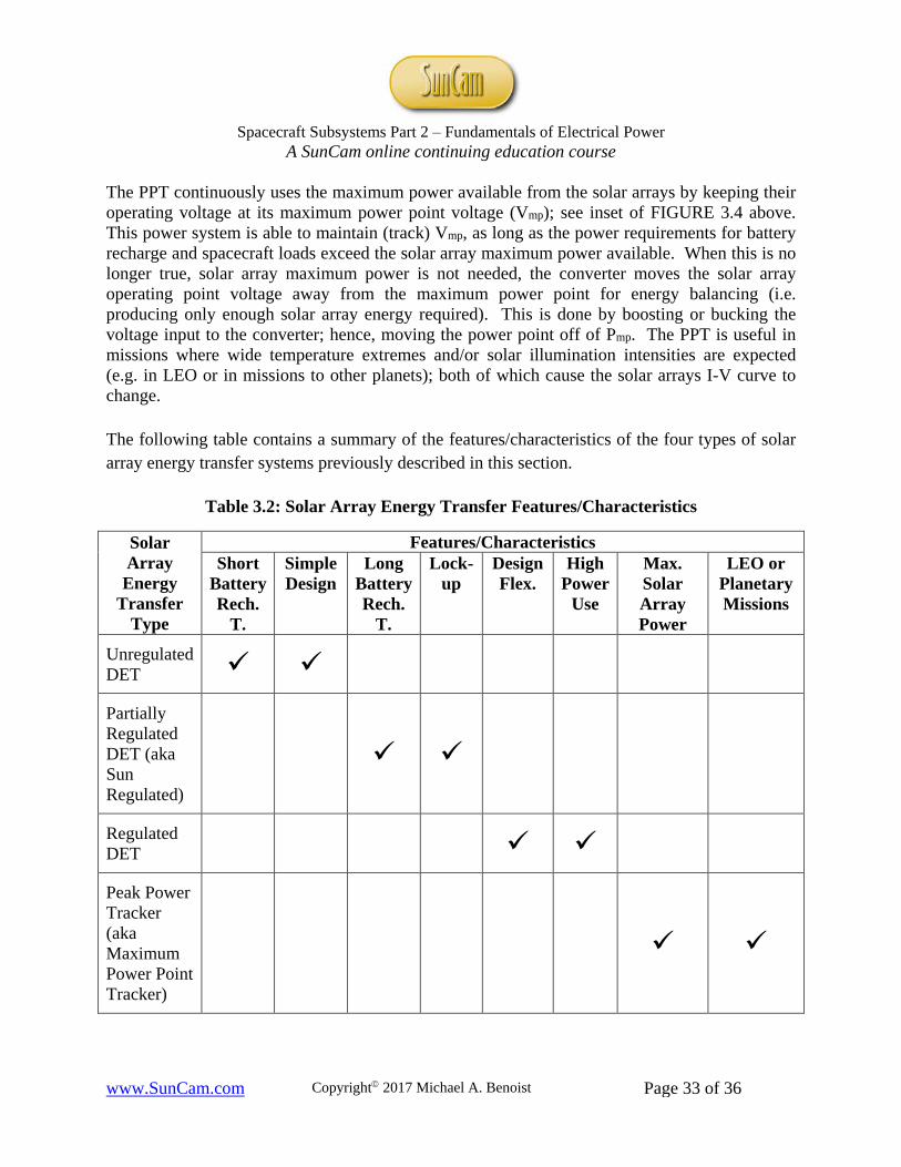
The PPT continuously uses the maximum power available from the solar arrays by keeping their operating voltage at its maximum power point voltage (Vmp); see inset of FIGURE 3.4 above. This power system is able to maintain (track) Vmp, as long as the power requirements for battery recharge and spacecraft loads exceed the solar array maximum power available. When this is no longer true, solar array maximum power is not needed, the converter moves the solar array operating point voltage away from the maximum power point for energy balancing (i.e. producing only enough solar array energy required). This is done by boosting or bucking the voltage input to the converter; hence, moving the power point off of Pmp. The PPT is useful in missions where wide temperature extremes and/or solar illumination intensities are expected (e.g. in LEO or in missions to other planets); both of which cause the solar arrays I-V curve to change. The following table contains a summary of the features/characteristics of the four types of solar array energy transfer systems previously described in this section.
Table 3.2: Solar Array Energy Transfer Features/Characteristics
Solar Array Energy
Transfer Type
Features/Characteristics Short
Battery Rech.
T.
Simple Design
Long Battery Rech.
T.
Lock-up
Design Flex.
High Power
Use
Max. Solar Array Power
LEO or Planetary Missions
Unregulated DET
Partially Regulated DET (aka Sun Regulated)
Regulated DET
Peak Power Tracker (aka Maximum Power Point Tracker)
Spacecraft Subsystems Part 2 ‒ Fundamentals of Electrical Power
A SunCam online continuing education course
www.SunCam.com Copyright 2017 Michael A. Benoist Page 34 of 36
Final Thoughts for this Section Once the solar array energy transfer type is selected, the solar array sizing needs to be done as follows: 1) Preliminary calculations of the solar array power required to recharge the batteries and power the spacecraft loads can be approximated using the following:
• load power • battery charge time • battery discharge time • average battery charge voltage • average battery discharge voltage • solar array power utilization factor: the ratio of nominal to maximum battery voltages
(for unregulated type only) • battery ampere hour recharge fraction (i.e. battery ampere hour inefficiency) • discharge diode circuit efficiency (for partial regulated type only) • charger circuit efficiency (for partial regulated and regulated types only) • peak power tracker converter efficiency (for peak power tracker type only) • peak power tracker accuracy (for peak power tracker type only)
2) From the solar array power required found from 1) you can then approximate the following: • number of solar cell strings (and cells per string) • total solar array area

Spacecraft Subsystems Part 2 ‒ Fundamentals of Electrical Power
A SunCam online continuing education course
www.SunCam.com Copyright 2017 Michael A. Benoist Page 35 of 36
References
1. Benoist, Michael, A., Spacecraft Subsystems Part 1 ‒ Fundamentals of Attitude Control, 2015, suncam.com.
2. Pisacane, Vincent L., Fundamentals of Space Systems, Oxford University Press, Inc, 2005.
3. Patel, Mukund, R., Spacecraft Power Systems, CRC Press, 2005.
4. Roddy, Dennis, Satellite Communications, Prentice-Hall, Inc., 1989.
5. NASA, International Space Station, Solar Arrays, 2016, nasa.gov.
6. NASA, Space Shuttle, STS-125 Mission Information, 2016, nasa.gov.
7. MIT 16.885J Aircraft Systems Engineering, Fall 2005, youtube.com.
8. NASA, Commercial Crew Transportation Capability (CCtCap), Acronym List (Attachment J-05) Solicitation NNK14467515R, 2016, nasa.gov.
9. NASA, Marshall History, Space Stations Imagery, 2016, nasa.gov.
10. NASA, Van Allen Probes in Space, 8/30/13, nasa.gov.
11. NASA, Relativistic Electron Proton Telescope (REPT), 11/9/12, nasa.gov.
12. NASA, Detailed Chronology of Events Surrounding the Apollo 13 Accident, 2016, nasa.gov.
13. NASA, Apollo 13, 7/8/9, nasa.gov.
14. NASA, Van Allen Radiation Belts, 7/19/12, nasa.gov.
15. NASA, Data Returned by RBSP'S REPT-A Instrument, 11/9/12, nasa.gov.
16. NASA, SDO Captures Stunning View of April 17 Solar Flare, 4/26/16, nasa.gov.
17. NASA, Mission to Hubble, Fact Sheet, Hubble Space Telescope Servicing Mission 4 Batteries, 2016, nasa.gov.
18. NASA, Apollo Service Module, 2016, nasa.gov.
19. NASA, Mission to Saturn, Cassini-Huygens, 2016, nasa.gov.
20. NASA, Radioisotope Power Systems, Mars Science Laboratory, 2016, nasa.gov.
21. NASA, Mars Microrover Power Subsystem, 2016, nasa.gov.
22. NASA, Cassini spacecraft, an artist rendition orbiting Saturn, 2016, nasa.gov.
Spacecraft Subsystems Part 2 ‒ Fundamentals of Electrical Power
A SunCam online continuing education course
www.SunCam.com Copyright 2017 Michael A. Benoist Page 36 of 36
23. NASA, Radioisotope Power Systems, 2016, nasa.gov.
24. NASA, Solar System Exploration, Galileo: Facts & Figures, 2016, nasa.gov.
25. NASA, Solar System Exploration, Ulysses: By the Numbers, 2016, nasa.gov.
26. NASA, Cassini, Mission to Saturn, About the Mission, 2016, nasa.gov.
27. NASA, New Horizons Mission Powered by Space Radioisotope Power Systems, 1/30/98, nasa.gov.
28. NASA, New Horizons, The First Mission to Pluto and Kuiper Belt: Exploring Frontier Words, Launch Press Kit, January 2006, nasa.gov.
29. NASA, Solar Dynamics Observatory (SDO), 2016, nasa.gov.
Note: If there was no date on a sourced website article, 2016 represents the year the article was accessed.