Embed Size (px)
Citation preview
8/10/2019 Space Weather Effects on Space Missions
http://slidepdf.com/reader/full/space-weather-effects-on-space-missions 1/37
SPACE WEATHERSPACE WEATHERSPACE WEATHERSPACE WEATHEREFFECTS ON SPACE MISSIONSEFFECTS ON SPACE MISSIONSEFFECTS ON SPACE MISSIONSEFFECTS ON SPACE MISSIONS
2012 | SSS EDUCATIONAL SERIES
8/10/2019 Space Weather Effects on Space Missions
http://slidepdf.com/reader/full/space-weather-effects-on-space-missions 2/37
SPACE
Contributors: ChEkRo
2
S V
i
+
© SSS
EATHER EFFECPACE MISSIONS
ijioke (CJ) Nwosa Nigeriaterina Rezugina Russiay Seth Canada
012 SPACE GENERATION ADVISOR
chwarzenbergplatz 6ienna [email protected] 1 718 11 18 30 Fax: +43 1 718 11 18
Educational Series 2012
S ON
COUNCIL
99
8/10/2019 Space Weather Effects on Space Missions
http://slidepdf.com/reader/full/space-weather-effects-on-space-missions 3/37
© SSS Educational Series 2012
Acknowledgments The SSS Working Group would like to thank SSS members for their collaboration and
contribution to the Space Weather Effects on Space Missions Educational Seriesdocument. In addition, we would like to express our gratitude to the SSS Advisory Team;Ronald Kohl, Shannon Ryan, Maite Trujillo and Brian Weeden for their expertise andguidance that have been critical to the completion of the project. Furtheracknowledgement goes to Ariane Cornell and Marc Cornwall for their review commentsand formatting advice.
Regards,Minoo Rathnasabapathy, Chijioke (CJ) NwosaSSS Co-leads
Proud PaProud PaProud PaProud Partners of SSS Working Group:rtners of SSS Working Group:rtners of SSS Working Group:rtners of SSS Working Group:
8/10/2019 Space Weather Effects on Space Missions
http://slidepdf.com/reader/full/space-weather-effects-on-space-missions 4/37
© SSS Educational Series 2012
Table of ContentsSection I: Residual Atmosphere Effects ................................................................................ 11. Introduction ...................................................................................................... ............12. Earth’s Atmosphere ............................................................................................... .......13. Atmospheric Effects ................................................................................................ ......2
3.1 Drag.............................................................................................................................. 2
3.2 Outgassing and Contamination.................................................................................. 4
3.3 Glow............................................................................................................................. 4
3.4 Surface Degradation/Erosion...................................................................................... 4
3.5 Aerodynamic Heating.................................................................................................. 5
4. Representative Cases ................................................................................................ ....54.1 Skylab........................................................................................................................... 5
4.2 Hubble Space Telescope............................................................................................. 6
4.3 International Space Station......................................................................................... 6
4.4 Long Duration Exposure Facility................................................................................. 6
5. Mitigation of Atmospheric Effects ................................................................................ 66. References .................................................................................................................... 7
Section II: Radiation Effects .................................................................................................. 81. Introduction .................................................................................................................. 82. Radiation Sources in Space ........................................................................................... 8
2.1 Radiation Belts............................................................................................................. 8
2.2 Cosmic Rays................................................................................................................. 9
2.3 Solar Particles............................................................................................................. 10
2.4. Atmospheric Secondaries......................................................................................... 10
3. Particle Radiation Effects ............................................................................................ 11
3.1 Ionising Radiation...................................................................................................... 11
3.2 Plasma........................................................................................................................ 14
3.3 Non-Ionising Dose/Non-Ionising Energy Loss (NIEL) .............................................. 15
4. Examples of Effects..................................................................................................... 16
4.1 Satellites..................................................................................................................... 16
4.2 Space Launch Vehicles............................................................................................... 17
8/10/2019 Space Weather Effects on Space Missions
http://slidepdf.com/reader/full/space-weather-effects-on-space-missions 5/37
© SSS Educational Series 2012
4.3 Humans....................................................................................................................... 17
5. Representative Cases .................................................................................................. 186. Mitigation of Radiation Effects ................................................................................... 187. References .................................................................................................................. 19
Section III: Thermal Effects.................................................................................................. 221. Introduction ................................................................................................................ 222. Thermal Sources in Space ........................................................................................... 22
2.1 Electromagnetic Radiation from the Sun.................................................................. 22
2.2 Solar Wind Heating.................................................................................................... 23
3. Thermal Effects ........................................................................................................... 24
3.1 Governance of Thermal Output from the Sun ......................................................... 24
4. Examples of Thermal Effects ....................................................................................... 25
4.1 Satellites..................................................................................................................... 25
4.2 Launch Vehicles.......................................................................................................... 25
4.3 Humans....................................................................................................................... 25
5. Mitigation of Thermal Effects ...................................................................................... 26
5.1 Satellites..................................................................................................................... 26
5.2 Launch Vehicles.......................................................................................................... 27
5.3 Humans....................................................................................................................... 28
6. References .................................................................................................................. 30
8/10/2019 Space Weather Effects on Space Missions
http://slidepdf.com/reader/full/space-weather-effects-on-space-missions 6/37
© SSS Educational Series 2012
1
Section I: Residual Atmosphere Effects
Section I: Residual Atmosphere Effects1.1.1.1. IntroductionIntroductionIntroductionIntroduction
The saying that “outer space is a vacuum” does not apply to all regions of space.Spacecraft in LEO, especially those below 550 km, are still within the reach of theEarth’s atmosphere and have to carry out their operations successfully whilesubjected to the effects of the atomic and/or molecular atmospheric constituents. Inthis section, the components of the Earth’s atmosphere which spacecraft areexposed to and the different interactions are outlined.
2.2.2.2. EarthEarthEarthEarth’s A’s A’s A’s Atmospheretmospheretmospheretmosphere
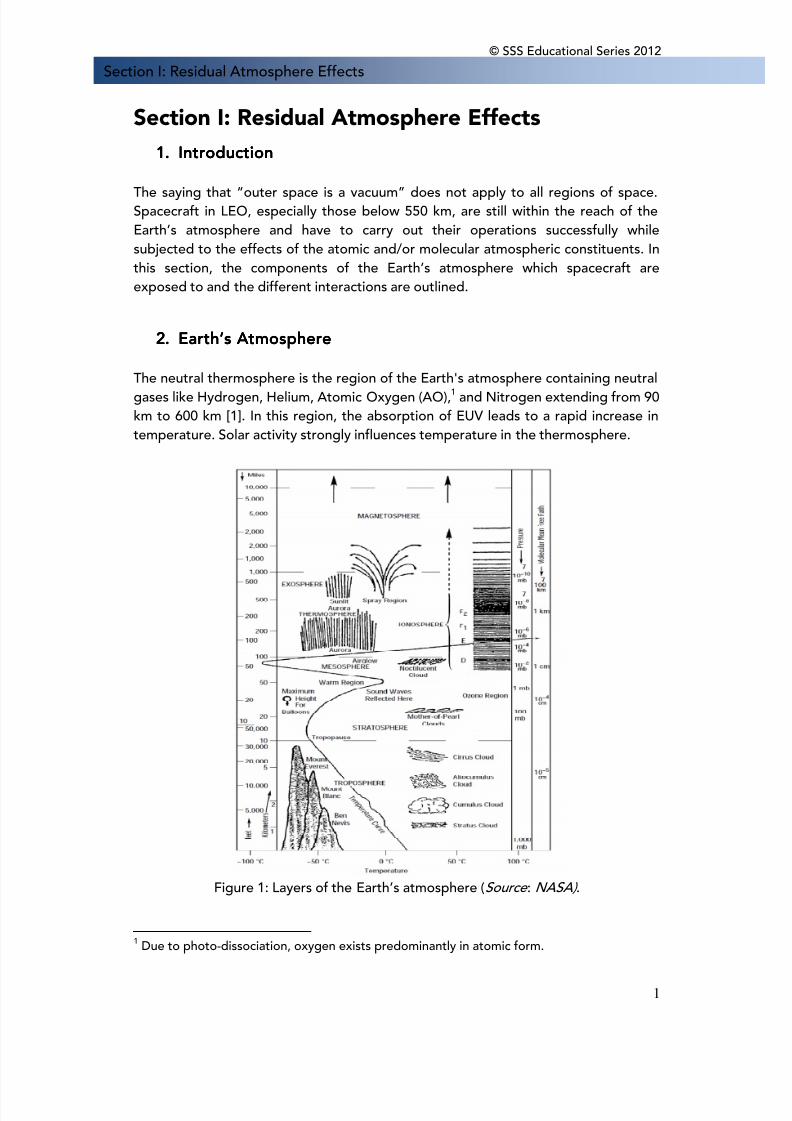
The neutral thermosphere is the region of the Earth's atmosphere containing neutralgases like Hydrogen, Helium, Atomic Oxygen (AO),1 and Nitrogen extending from 90km to 600 km [1]. In this region, the absorption of EUV leads to a rapid increase intemperature. Solar activity strongly influences temperature in the thermosphere.
Figure 1: Layers of the Earth’s atmosphere (Source : NASA) .
1 Due to photo-dissociation, oxygen exists predominantly in atomic form.
8/10/2019 Space Weather Effects on Space Missions
http://slidepdf.com/reader/full/space-weather-effects-on-space-missions 7/37
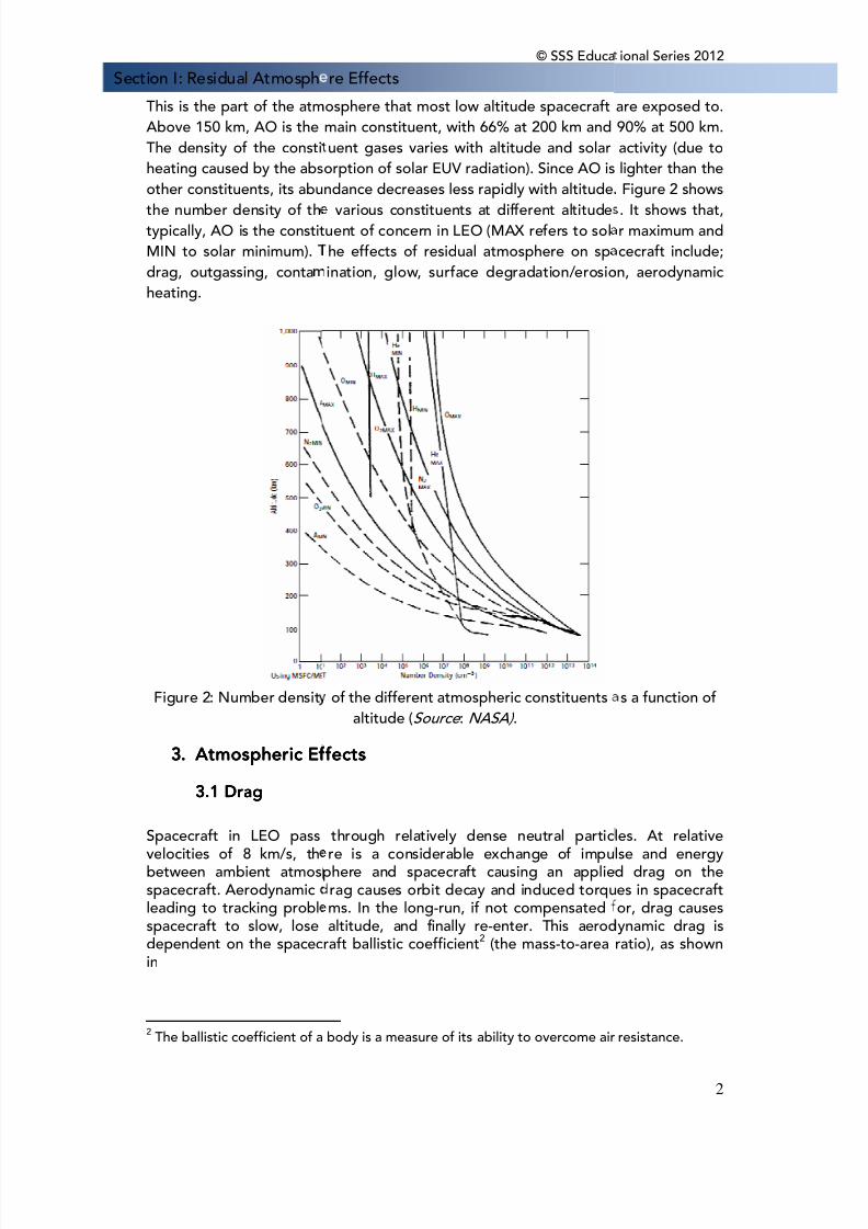
Section I: Residual AtmosphThis is the part of the atmAbove 150 km, AO is theThe density of the constiheating caused by the absother constituents, its abuthe number density of thtypically, AO is the constitMIN to solar minimum).drag, outgassing, contaheating.
Figure 2: Number densit
3.3.3.3. AtmosphericAtmosphericAtmosphericAtmospheric EEEEffff
3.13.13.13.1 DragDragDragDrag
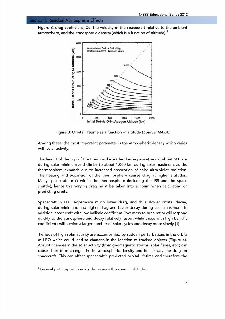
Spacecraft in LEO passvelocities of 8 km/s, thbetween ambient atmosspacecraft. Aerodynamicleading to tracking problspacecraft to slow, losedependent on the spacecin
2 The ballistic coefficient of a
© SSS Educare Effectsosphere that most low altitude spacecraftmain constituent, with 66% at 200 km anduent gases varies with altitude and solarorption of solar EUV radiation). Since AO isndance decreases less rapidly with altitude.
various constituents at different altitudeuent of concern in LEO (MAX refers to solhe effects of residual atmosphere on spination, glow, surface degradation/erosio
of the different atmospheric constituentsaltitude (Source : NASA) .
fectsfectsfectsfects
through relatively dense neutral particre is a considerable exchange of impu
phere and spacecraft causing an applierag causes orbit decay and induced torqums. In the long-run, if not compensatedaltitude, and finally re-enter. This aerod
raft ballistic coefficient2 (the mass-to-area
body is a measure of its ability to overcome air
ional Series 2012
2
are exposed to.90% at 500 km.activity (due tolighter than theFigure 2 shows. It shows that,r maximum andcecraft include;n, aerodynamic
s a function of
les. At relativelse and energyd drag on thees in spacecraftor, drag causesynamic drag isratio), as shown
resistance.
8/10/2019 Space Weather Effects on Space Missions
http://slidepdf.com/reader/full/space-weather-effects-on-space-missions 8/37
8/10/2019 Space Weather Effects on Space Missions
http://slidepdf.com/reader/full/space-weather-effects-on-space-missions 9/37
© SSS Educational Series 2012
4
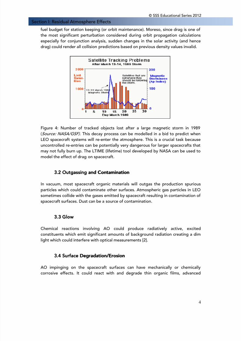
Section I: Residual Atmosphere Effectsfuel budget for station keeping (or orbit maintenance). Moreso, since drag is one ofthe most significant perturbation considered during orbit propagation calculationsespecially for conjunction analysis, sudden changes in the solar activity (and hencedrag) could render all collision predictions based on previous density values invalid.
Figure 4: Number of tracked objects lost after a large magnetic storm in 1989(Source: NASA/GSF). This decay process can be modelled in a bid to predict whenLEO spacecraft systems will re-enter the atmosphere. This is a crucial task becauseuncontrolled re-entries can be potentially very dangerous for larger spacecrafts thatmay not fully burn up. The LTIME (lifetime) tool developed by NASA can be used tomodel the effect of drag on spacecraft.
3.2 Outgassing and C3.2 Outgassing and C3.2 Outgassing and C3.2 Outgassing and Contaminationontaminationontaminationontamination
In vacuum, most spacecraft organic materials will outgas the production spuriousparticles which could contaminate other surfaces. Atmospheric gas particles in LEOsometimes collide with the gases emitted by spacecraft resulting in contamination ofspacecraft surfaces. Dust can be a source of contamination.
3.3 Glow3.3 Glow3.3 Glow3.3 Glow
Chemical reactions involving AO could produce radiatively active, excitedconstituents which emit significant amounts of background radiation creating a dimlight which could interfere with optical measurements [2].
3.4 Surface D3.4 Surface D3.4 Surface D3.4 Surface Degradation/Erosionegradation/Erosionegradation/Erosionegradation/Erosion
AO impinging on the spacecraft surfaces can have mechanically or chemicallycorrosive effects. It could react with and degrade thin organic films, advanced
8/10/2019 Space Weather Effects on Space Missions
http://slidepdf.com/reader/full/space-weather-effects-on-space-missions 10/37
© SSS Educational Series 2012
5
Section I: Residual Atmosphere Effectscomposites, and metallised surfaces. This erosion of the spacecraft surfaces affectsits thermal, electrical, mechanical, and optical properties.4
Under AO exposure:• Silver contacts form silver oxide layers which are porous to AO and flake off due
to stresses generated from thermal cycling. Hence AO is able to penetrate andreact with the underlying fresh silver.
• In the same way, silicon based materials form silicone dioxide layers which affectoptical transparency of solar cells, optical cover glasses etc.
• Most metals like aluminium produce protective oxide layers that are imperviousto AO and hence resistant to further attack.
• The ATOMOX (Atomic Oxygen) tool developed by ESA can be used to calculatethe AO fluence (atoms/m2) on spacecraft surfaces. Moreso, a number ofatmospheric and ionospheric models are available:- Mass-Spectrometer-Incoherent-Scatter (NRLMSISE-00) [7]- Marshall Engineering Thermosphere (MET-V 2.0) [8]- Drag Temperature Model (DTMB78)- Horizontal Wind Model (HWM93) [9]- International Reference Ionosphere (IRI2001) [10]- NeQuick Ionosphere Electron Density Model (NeQuick v2.0) [11]
3.5 Aerodynamic Heating3.5 Aerodynamic Heating3.5 Aerodynamic Heating3.5 Aerodynamic Heating
Most spacecraft orbit in LEO with a minimum orbital period of 87.5 minutescorresponding to an altitude of 150 km. Spacecraft in LEO get heated by forcedconvection as they pass through the ambient atmosphere. The magnitude of thisaerodynamic heating at 150 km altitude is that of the solar constant. From here, itdecreases with increasing altitude. This is a huge concern especially for spacecraft inhighly elliptical orbits (e.g. Molniya orbits) with perigees lower than 150 km. In somecases, depending on the ballistic coefficient, spacecraft systems could completelyburn up in the atmosphere during re-entry due to aerodynamic heating.
4.4.4.4. Representative CRepresentative CRepresentative CRepresentative Casesasesasesases4.1 Skylab4.1 Skylab4.1 Skylab4.1 Skylab
On July 11, 1979, Skylab fell back to Earth earlier than planned due to increaseddrag in the neutral thermosphere [3].
4 These effects are aggravated by simultaneous exposure to solar UV radiation,micrometeoroid impact damage, sputtering, and contamination.
8/10/2019 Space Weather Effects on Space Missions
http://slidepdf.com/reader/full/space-weather-effects-on-space-missions 11/37
© SSS Educational Series 2012
6
Section I: Residual Atmosphere Effects4.2 Hubble Space Telescope4.2 Hubble Space Telescope4.2 Hubble Space Telescope4.2 Hubble Space Telescope
The Hubble Space Telescope (HST) drops about 10 - 15 km per year and has beenperiodically re-boosted by the shuttle.
4.3 International Space Station4.3 International Space Station4.3 International Space Station4.3 International Space Station
The International Space Station (ISS) requires re-boosting several times a year due toa drag induced average orbit decay of 83 m per day. In addition, the retrievedsilicone oxide coated retroreflectors mounted on the e., trapped protons cease toexist at the poles, but high energy trapped protons continue to feature in the SAA.External surfaces of the ISS showed AO erosion of the unprotected areas.
4.4 Long Duration Exposure Facility4.4 Long Duration Exposure Facility4.4 Long Duration Exposure Facility4.4 Long Duration Exposure Facility
In June 1984, Aluminised polyimide Kapton® insulation samples on the leading edgeof recovered surfaces of the Long Duration Exposure Facility (LDEF) experiencedsignificant erosion due to AO. This led to degradation of the underlying spacecraftmaterials [4].
5.5.5.5. Mitigation of Atmospheric EffectsMitigation of Atmospheric EffectsMitigation of Atmospheric EffectsMitigation of Atmospheric Effects
• Routine orbit reboost and manoeuvres correct for spacecraft orbit decay fromdrag effects.5
• Various coatings are used to protect against AO effects:- Silicone dioxide, fluoropolymer filled silicon dioxide, aluminum oxide and
germanium can be sputter deposited on polymers. For example, the largesolar array blankets of the ISS have been coated with silicone dioxide for AOprotection.
- Vapour deposited gold used on silver electrical contacts.- Silverised or aluminised perfluorinated ethylenepropylene film due to its low
sensitivity to AO erosion6
[5].- AOR (Atomic Oxygen Resistant) Kapton®, a polydimethyl silioxane-polyimidemixture [6].
5 Not all spacecraft have this ability, particularly nanosats and cubesats due to weight andsize constraints, as an inbuilt propulsion system is required.6
Aluminized perfluorinated ethylenepropylene film is regularly used for insulation purposesbecause of its thermo-optical properties, low solar absorptance, and high thermalemmittance.
8/10/2019 Space Weather Effects on Space Missions
http://slidepdf.com/reader/full/space-weather-effects-on-space-missions 12/37
© SSS Educational Series 2012
7
Section I: Residual Atmosphere Effects6.6.6.6. ReferencesReferencesReferencesReferences
[1] The Upper Atmosphere. The Space Environment and Survivability. Walterscheid,R. L. 1999, Space Mission Analysis and Design, pp. 207-212.
[2] Hastings, D. and Garret, H. Spacecraft Environment Interactions. s.l. : CambridgeUniversity Press., 2004.
[3] Spacecraft Interactions with the Space Environment. Tribble, A. C. Reno. : AIAA33rd Aerospace Sciences Meeting and Exhibit., 1995.
[4] Atomic Oxygen Undercutting of Long Duration Exposure Facility Aluminised-Kapton Multilayer Insulation. De Groh, et al. 4, s.l. : Journal of Spacecraft andRockets., 1994, Vol. 31, pp. 656-664.
[5] Preliminary Investigations into UHCRE Thermal Control Materials. Levadou, F. M.et al.. 1992.
[6] The Effect of Atomic Oxygen on Altered and Coated Kapton Surfaces forSpacecraft Applications in Low Earth Orbit. Rutledge, S. and Mihelcic, J. 1990.
[7] Hedin, A. E. Extension of the MSIS Thermosphere Model into the Middle andLower Atmosphere. Journal of Geophysical Research. Vol. 96, pp 1159. 1991.
[8] Owens, J. K. NASA Marshall Engineering Thermosphere Model-Version 2.0.NASA/TM−2002-211786. 2002.
[9] Hedin, A. E. et al. Revised Global Model of Thermosphere Winds Using Satelliteand Ground-Based Observations. Journal of Geophysical Research. Vol. 96, pp7657-7688. 1991.
[10] Bilitza, D. International Reference Ionosphere 2000. Radio Science. Vol. 36, pp261-275. 2001.
[11] Nava, B. et al. A new version of the NeQuick ionosphere electron density model.Journal of Atmospheric and Solar-Terrestrial Physics. Vol. 70, pp 1856-1862, 2008.
8/10/2019 Space Weather Effects on Space Missions
http://slidepdf.com/reader/full/space-weather-effects-on-space-missions 13/37
© SSS Educational Series 2012
8
Section II: Radiation Effects
Section II: Radiation Effects1.1.1.1. IntroductionIntroductionIntroductionIntroduction
Space systems (satellites, launchers and the ISS) and human beings in space arevulnerable to Space Weather through its influence on energetic charged particle andplasma populations, which produce a variety of effects, including total dose, latticedisplacement damage, Single Event Effects (SEE), noise in sensors and electrostaticcharging. In addition aircraft electronics and aircrew are subjected to atmosphericsecondary radiation produced by cosmic rays and solar particle events.
2.2.2.2. Radiation SRadiation SRadiation SRadiation Sources inources inources inources in SpaceSpaceSpaceSpace
2222.1 Radiation B.1 Radiation B.1 Radiation B.1 Radiation Beltseltseltselts
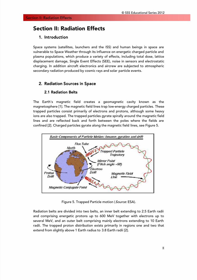
The Earth's magnetic field creates a geomagnetic cavity known as themagnetosphere [1]. The magnetic field lines trap low-energy charged particles. Thesetrapped particles consist primarily of electrons and protons, although some heavyions are also trapped. The trapped particles gyrate spirally around the magnetic fieldlines and are reflected back and forth between the poles where the fields areconfined [2]. Charged particles gyrate along the magnetic field lines, see Figure 5.
Figure 5. Trapped Particle motion (Source : ESA).
Radiation belts are divided into two belts, an inner belt extending to 2.5 Earth radiiand comprising energetic protons up to 600 MeV together with electrons up toseveral MeV, and an outer belt comprising mainly electrons extending to 10 Earthradii. The trapped proton distribution exists primarily in regions one and two thatextend from slightly above 1 Earth radius to 3.8 Earth radii [2].
8/10/2019 Space Weather Effects on Space Missions
http://slidepdf.com/reader/full/space-weather-effects-on-space-missions 14/37
© SSS Educational Series 2012
9
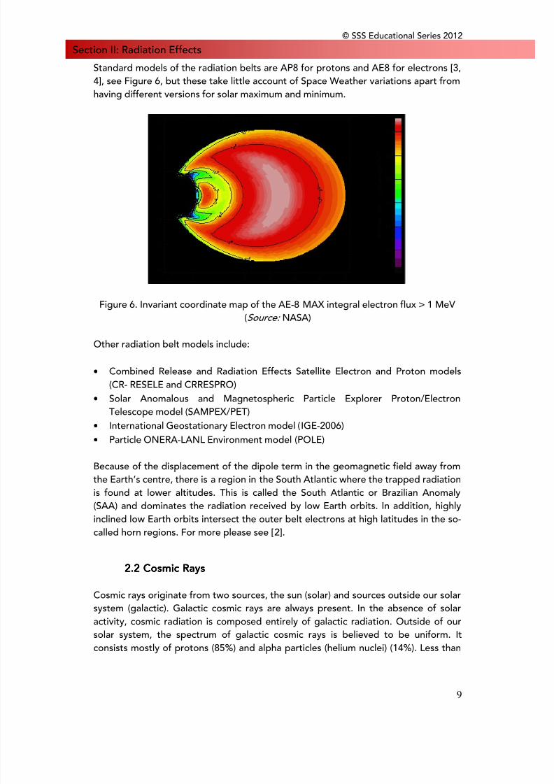
Section II: Radiation EffectsStandard models of the radiation belts are AP8 for protons and AE8 for electrons [3,4], see Figure 6, but these take little account of Space Weather variations apart fromhaving different versions for solar maximum and minimum.
Figure 6. Invariant coordinate map of the AE-8 MAX integral electron flux > 1 MeV(Source: NASA)
Other radiation belt models include:
• Combined Release and Radiation Effects Satellite Electron and Proton models
(CR- RESELE and CRRESPRO)• Solar Anomalous and Magnetospheric Particle Explorer Proton/Electron
Telescope model (SAMPEX/PET)• International Geostationary Electron model (IGE-2006)• Particle ONERA-LANL Environment model (POLE)
Because of the displacement of the dipole term in the geomagnetic field away fromthe Earth’s centre, there is a region in the South Atlantic where the trapped radiationis found at lower altitudes. This is called the South Atlantic or Brazilian Anomaly(SAA) and dominates the radiation received by low Earth orbits. In addition, highlyinclined low Earth orbits intersect the outer belt electrons at high latitudes in the so-called horn regions. For more please see [2].
2222.2 Cosmic Rays.2 Cosmic Rays.2 Cosmic Rays.2 Cosmic Rays
Cosmic rays originate from two sources, the sun (solar) and sources outside our solarsystem (galactic). Galactic cosmic rays are always present. In the absence of solaractivity, cosmic radiation is composed entirely of galactic radiation. Outside of oursolar system, the spectrum of galactic cosmic rays is believed to be uniform. Itconsists mostly of protons (85%) and alpha particles (helium nuclei) (14%). Less than
8/10/2019 Space Weather Effects on Space Missions
http://slidepdf.com/reader/full/space-weather-effects-on-space-missions 15/37
© SSS Educational Series 2012
10
Section II: Radiation Effects1% of the galactic cosmic ray spectrum is composed of high-energy heavy ions.Heavy ions deposit more energy per unit depth in a material than protons [2]. Fromthe point of view of space systems it is particles in the energy range 1-20 GeV pernucleon which have most influence, because it is hard to shield against them and it isnot possible to predict a coming impact. An important quantity is the rigidity of acosmic ray which measures its resistance to bending in a magnetic field and isdefined as the momentum-to-charge ratio for which typical units are GV. Theinfluence of Space Weather is to provide a modulation in antiphase with the sunspotcycle and with a phase lag which is dependent on energy [5], for more please see Ref[2].
2222.3 Solar Particles.3 Solar Particles.3 Solar Particles.3 Solar Particles
In the years around solar maximum the sun is an additional sporadic source of lowerenergy particles accelerated during certain solar flares and in the subsequent coronalmass ejections. These solar particle events last for several days at a time andcomprise both protons and heavier ions with variable composition from event toevent. Energies typically range up to several hundred MeV and have most influenceon high inclination or high altitude systems. Occasional events produce particles ofseveral GeV in energy and these can reach equatorial latitudes [5].
Solar proton models include:• The King model [28]
• The Jet Propulsion Laboratory (JPL) model [29]• The Rosenqvist et al. model [30]• The Emission of Solar Protons (ESP) model [31]
For solar heavy ions, the PSYCHIC model (Prediction of Solar Particle Yields forCharacterising Integrated Circuits) is available.
2222.4. Atmospheric Secondaries.4. Atmospheric Secondaries.4. Atmospheric Secondaries.4. Atmospheric Secondaries
The primary cosmic rays interact with air nuclei to generate a cascade of secondaryparticles comprising protons, neutrons, mesons, electrons, photons and nuclearfragments. The intensity of radiation builds up to a maximum at 60 000 feet (thePfotzer maximum) and then slowly drops off to sea level. At normal aircraft cruisingaltitudes the radiation is several hundred times the ground level intensity and at60 000 feet a factor three higher again. Solar particles are less penetrating and only afew events in each cycle can reach aircraft altitudes or ground level [5].
8/10/2019 Space Weather Effects on Space Missions
http://slidepdf.com/reader/full/space-weather-effects-on-space-missions 16/37
© SSS Educational Series 2012
11
Section II: Radiation Effects3.3.3.3. Particle Radiation EffectsParticle Radiation EffectsParticle Radiation EffectsParticle Radiation Effects
3333.1.1.1.1 IonisingIonisingIonisingIonising RRRRadiationadiationadiationadiation
3333.1.1 Total Dose E.1.1 Total Dose E.1.1 Total Dose E.1.1 Total Dose Effectsffectsffectsffects
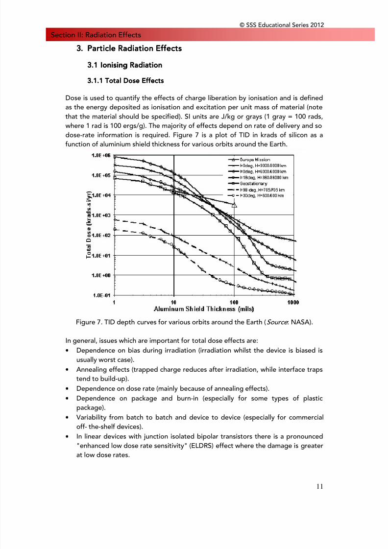
Dose is used to quantify the effects of charge liberation by ionisation and is definedas the energy deposited as ionisation and excitation per unit mass of material (notethat the material should be specified). SI units are J/kg or grays (1 gray = 100 rads,where 1 rad is 100 ergs/g). The majority of effects depend on rate of delivery and sodose-rate information is required. Figure 7 is a plot of TID in krads of silicon as afunction of aluminium shield thickness for various orbits around the Earth.
Figure 7. TID depth curves for various orbits around the Earth (Source : NASA).
In general, issues which are important for total dose effects are:• Dependence on bias during irradiation (irradiation whilst the device is biased is
usually worst case).• Annealing effects (trapped charge reduces after irradiation, while interface traps
tend to build-up).• Dependence on dose rate (mainly because of annealing effects).• Dependence on package and burn-in (especially for some types of plastic
package).• Variability from batch to batch and device to device (especially for commercial
off- the-shelf devices).• In linear devices with junction isolated bipolar transistors there is a pronounced
"enhanced low dose rate sensitivity" (ELDRS) effect where the damage is greaterat low dose rates.
8/10/2019 Space Weather Effects on Space Missions
http://slidepdf.com/reader/full/space-weather-effects-on-space-missions 17/37
© SSS Educational Series 2012
12
Section II: Radiation EffectsOf relevance to potential work under this project is the problem of dose-enhancement under electron or bremsstrahlung radiation where there areboundaries between materials of widely differing atomic number [6].
3333.1.2 Displacement D.1.2 Displacement D.1.2 Displacement D.1.2 Displacement Damageamageamageamage
Energetic particles such as neutrons, protons, electrons, a-particles and heavy ionscan create damage in semiconductor materials by displacing atoms in the crystallattice. Secondary electrons produced by high-energy photons will also producedisplacement effects. The result is that stable defect states are created within theband gap that can give rise to any of the five effects depending on the temperature,carrier concentration and the location at which the defect resides [7]:
• Generation of electron-hole pairs (leading to thermal dark current in detectors);• Recombination of electron-hole pairs (leading to reduction of minority carrier
lifetime and effects in LEDs and laser diodes);• Trapping of carriers, leading to loss in charge transfer efficiency in CCDs
(minority carrier trapping) or carrier removal (majority carrier trapping);• Compensation of donors or acceptors, also leading to carrier removal in some
devices (for example the resistance in a lightly doped collector in a bipolartransistor can increase);
• Tunneling of carriers, leading to increased current in reverse biased junctions -particularly for small bandgap materials and high electric fields.
It is now well established that the amount of formation of defect clusters depends onthe particle type. Electron irradiation gives primary knock-on atoms (PKAs) with lowrecoil energies and hence leads to almost exclusive production of point defects;whereas neutrons give a flat PKA spectrum and a much greater proportion of clusterformation. For protons the situation is in between [6].
3333.1.3 Single Event E.1.3 Single Event E.1.3 Single Event E.1.3 Single Event Effectsffectsffectsffects
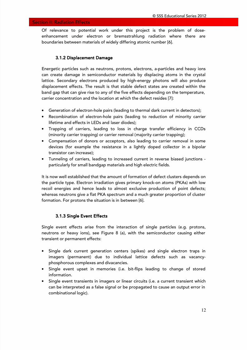
Single event effects arise from the interaction of single particles (e.g. protons,neutrons or heavy ions), see Figure 8 (a), with the semiconductor causing eithertransient or permanent effects:
• Single dark current generation centers (spikes) and single electron traps inimagers (permanent) due to individual lattice defects such as vacancy-phosphorous complexes and divacancies.
• Single event upset in memories (i.e. bit-flips leading to change of storedinformation.
• Single event transients in imagers or linear circuits (i.e. a current transient which
can be interpreted as a false signal or be propagated to cause an output error incombinational logic).
8/10/2019 Space Weather Effects on Space Missions
http://slidepdf.com/reader/full/space-weather-effects-on-space-missions 18/37
Section II: Radiation Effects• Single event latch-up
parasitic p-n-p-n thyris• Single event burnout i
channel transistor acc•
Single event snapbacktriggering of a lateral• Single event functiona
(transient corruption o• Single event gate rupt
generated by high cur
Both the recoiling nucleuFigure 8 (b).
Figure 8. S
For cosmic rays the densisquare of the atomic numin a small volume of siliczero and vice versa [5].
3333.1..1..1..1.4 Biological E4 Biological E4 Biological E4 Biological Effff The radiation effects on(catalogue McNully). Ionibase damage in DNA. Ileading to loss of bases olatter is analogous to sindouble-strand breaks that
cancer. As with SEE, theinteractions [6].
© SSS Educa
in CMOS circuits (a potentially destructiveor structure in the device).power transistors (a destructive triggerin
mpanied by regenerative feedback).
in NMOS devices, particularly in SOI devic-p-n transistor accompanied by regeneratil interrupt in control circuitry, e.g. in proca control path).
ure (destructive rupture of gate dielectricent) [6].
s and secondary particles can trigger SE
E in an electronic device (Source : NASA JP
y of charge deposition by ionisation is prober so that the heavier species can depositn to change the state of a memory cell, a
fectsfectsfectsfects
human beings are similar to the effectsation produces free hydroxyl radicals whi
addition individual particles can breakr rupturing of the sugar phosphate backbole event effects in electronics and can remay not repair successfully resulting in t
harge deposition can be by direct ionisati
ional Series 2012
13
triggering of a
of a vertical n-
s (a destructivee feedback).ssors or ADCs,
ue to high field
Es as shown in
L)
portional to theenough chargene becoming a
on electronicsch may lead tochemical bondsne of DNA. Thesult in single ore possibility of
n or by nuclear
8/10/2019 Space Weather Effects on Space Missions
http://slidepdf.com/reader/full/space-weather-effects-on-space-missions 19/37
© SSS Educational Series 2012
14
Section II: Radiation EffectsEffects are divided into stochastic (e.g. cancer induction) where probability is afunction of dose and non-stochastic (e.g. eye cataracts) which definitely occurbeyond a threshold dose. Individual highly ionising particles can give light flashes inthe retina.
Currently human exposure is limited to Space Shuttle and International Space Stationorbits for which trapped protons in the SAA are a major concern. Heavy ions incosmic rays and occasional solar particle events are also of concern, while electronscan be important for extravehicular activity. In large space structures, secondaryneutrons become very significant and can provide a third of the dose equivalent forcertain missions [8, 9]. For interplanetary travel, cosmic-ray ions and solar particleevents are most significant and very large solar events could provide debilitatingdoses if inadequate shielding is provided.
Important issues include:• Determination of quality factors;• Microdosimetric calculations at the cell nucleus level, both for heavy ions (track
structure important) and for nuclear interactions by neutrons and protons;• Accurate shielding calculations to account for fragmentation of heavy ions and
production of secondary neutrons.
A review of this area has been given by Reitz et al [10].
3333.1.5 Background N.1.5 Background N.1.5 Background N.1.5 Background Noiseoiseoiseoise
Spurious counts are produced in many detector systems and these depend on thesize distribution of individual depositions and can occur from both prompt ionisationand delayed depositions due to induced radioactivity [5].
3333.2 Plasma.2 Plasma.2 Plasma.2 PlasmaPlasma is ionised gas in which electron and ion densities are approximately equal.The solar wind particles (positively charged ions and free electrons) ejected from theSun could be so hot that they are homogenised into a dilute plasma. The electricallyneutral plasma streams radially outwards from the Sun with temperatures up tohundreds of keV. The energy density of the plasma (about 1 to 30 particles/cm3)exceeds that of its magnetic field so that the solar magnetic field lines are frozen intothe plasma. In the geosynchronous environment, about 100% of the chargedparticles are ionised. This fraction reduces to about 1% at 300 km altitude.
8/10/2019 Space Weather Effects on Space Missions
http://slidepdf.com/reader/full/space-weather-effects-on-space-missions 20/37
© SSS Educational Series 2012
15
Section II: Radiation Effects3333....2.1 Electro2.1 Electro2.1 Electro2.1 Electrostatic (Spacecraft) Cstatic (Spacecraft) Cstatic (Spacecraft) Cstatic (Spacecraft) Chargingharginghargingharging
Surface charging can occur when spacecraft are bathed in energetic plasmas (severalkeV electron temperature) without the presence of neutralising cold plasma. This canoccur in the geomagnetic tail region during geomagnetic storms and the subsequentdischarges can couple into spacecraft systems. Internal charging, or deep dielectriccharging as it is commonly called, can occur during energetic (several MeV) electronenhancements. Electrons penetrating the thin skin can be trapped in dielectricmaterials near the surface and sufficient build-up can occur over a few days to resultin a damaging electron caused electromagnetic pulse (ECEMP) and electrostaticarcing [5].
Electromagnetic Interference (EMI) from such arcs could lead to operationalanomalies in spacecraft ranging from minor irritations to the fatally catastrophic. Thiscould be in the form of increased surface contamination and physical surface damageby ion sputtering, biasing of spacecraft instrument readings, and upsets to sensitiveelectronics. Some models used to analyse the effects of spacecraft charging are:
• NASA Charging Analyser Programme for Low-Earth Orbit (NASCAP/LEO)• NASA Charging Analyser Programme for Geosynchronous Orbit (NASCAP/GEO)• Potentials of Large spacecraft in Auroral Regions (POLAR)
3333.3 Non.3 Non.3 Non.3 Non----Ionising Dose/NonIonising Dose/NonIonising Dose/NonIonising Dose/Non----Ionising Energy Loss (NIEL)Ionising Energy Loss (NIEL)Ionising Energy Loss (NIEL)Ionising Energy Loss (NIEL)
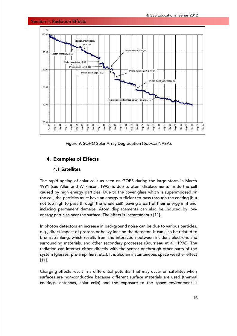
Energetic charged particles may collide with the atomic nuclei of materials theyimpinge on thereby displacing the atom from its crystal lattice site. The energeticdisplaced atom may subsequently collide with other atoms of the material. Thedisplacement defects reduce the minority carrier lifetimes and diffusion lengthsthereby decreasing efficiency of solar cells, photodetectors, optical lenses and lightemitting diodes. The total absorbed non-ionising dose is referred to as displacementdamage dose (Dd) expressed in units of MeVg-1. Figure 9 shows the Solar andHeliospheric Observatory's (SOHO) solar array degradation between December1995 and November 2009. Abrupt drops in the efficiency of the solar panels coincide
with solar events.
8/10/2019 Space Weather Effects on Space Missions
http://slidepdf.com/reader/full/space-weather-effects-on-space-missions 21/37
© SSS Educational Series 2012
16
Section II: Radiation Effects
Figure 9. SOHO Solar Array Degradation (Source : NASA).
4.4.4.4. Examples of EffectsExamples of EffectsExamples of EffectsExamples of Effects
4444.1 Satellites.1 Satellites.1 Satellites.1 Satellites
The rapid ageing of solar cells as seen on GOES during the large storm in March1991 (see Allen and Wilkinson, 1993) is due to atom displacements inside the cellcaused by high energy particles. Due to the cover glass which is superimposed onthe cell, the particles must have an energy sufficient to pass through the coating (butnot too high to pass through the whole cell) leaving a part of their energy in it andinducing permanent damage. Atom displacements can also be induced by low-energy particles near the surface. The effect is instantaneous [11].
In photon detectors an increase in background noise can be due to various particles,e.g., direct impact of protons or heavy ions on the detector. It can also be related tobremsstrahlung, which results from the interaction between incident electrons andsurrounding materials, and other secondary processes (Bourrieau et al., 1996). Theradiation can interact either directly with the sensor or through other parts of thesystem (glasses, pre-amplifiers, etc.). It is also an instantaneous space weather effect[11].
Charging effects result in a differential potential that may occur on satellites whensurfaces are non-conductive because different surface materials are used (thermalcoatings, antennas, solar cells) and the exposure to the space environment is
8/10/2019 Space Weather Effects on Space Missions
http://slidepdf.com/reader/full/space-weather-effects-on-space-missions 22/37
© SSS Educational Series 2012
17
Section II: Radiation Effectsdifferent for different surfaces (shadow, non-isotropic particle fluxes), especiallywhen surfaces are made of dielectric materials.
The external layer thickness of a satellite being usually around 500 microns, electronswith energies below 300 keV and protons below 8 MeV will generally be stopped inthe protecting material. For surface charging, the time scales depend on the materialor structure and the differential current [11].
The clearest examples of displacement effect arise from observations ofdegradations in solar-array efficiency where sharp drops can occur during solarparticle events. For example, drops in efficiency of 4% in GEO [12] and 2% in LEO[13].
For SEEs in electronics or computer devices, the particles responsible must pass
through the shielding of the satellite (thermal coating and structural materials) andthe cover and insulating materials of the electronics, so they must have a sufficientlyhigh energy.
More examples of Single Event Effects observed in spacecraft components can befound in Ref [6].
4444.2 Space Launch Vehicles.2 Space Launch Vehicles.2 Space Launch Vehicles.2 Space Launch Vehicles
Space launch vehicles, as they move higher out of the atmosphere are subject tonearly all other space weather effects (surface charging, global drag, SEEs byenergetic particles from radiation belt as well as solar energetic particles and cosmicrays, internal charging). Nevertheless, normally these effects do not have enoughtime to perturb the launcher, excepted during solar energetic particle events orwhen crossing during a long period of time the radiation belts (near the SouthAtlantic Anomaly), which is the case for Ariane V launches to GTO or interplanetaryorbits [11, 14]. The exception is upper stages that have to do additionalmanoeuvres to place satellites in deep space orbits. This can sometimes take weeksor months.
Single Event Upsets were recorded during an Ariane V launch without any solarenergetic particle event in progress [11]. The number of SEUs can increase duringsuch an event. Nevertheless, the redundancy of computers on board this launchermakes fatal error unlikely [11].
4444.3 Humans.3 Humans.3 Humans.3 Humans
During Extra Vehicular Activities (EVAs), nearly all effects similar to spacecraft are
possible, the suit being similar to the satellite and the shielding being smaller(around 0.5 mm). Charging effects and energetic particles (protons from the
8/10/2019 Space Weather Effects on Space Missions
http://slidepdf.com/reader/full/space-weather-effects-on-space-missions 23/37
© SSS Educational Series 2012
18
Section II: Radiation Effectsradiation belts and ions from the cosmic rays or SEPEs) occur on low-altitude stations(ISS, MIR) and lower than 400 km where the inner Van Allen radiation belts effectivelyconfine human orbital spaceflight around Earth to lower than 400 km (the lowestpoint of the South Atlantic Anomaly). However, charging effects can appearespecially when astronauts cross the boundary between sunlight and shadow.
During the potential future interplanetary missions, or missions to the Moon,astronauts are not protected by the magnetospheric shielding and the fluxes aremuch higher [11, 15].
5.5.5.5. Representative CasesRepresentative CasesRepresentative CasesRepresentative Cases
• Anik E2 On January 20, 1994, Telesat's Anik E2 lost attitude control due to a
malfunction of the primary momentum wheel. The redundant unit failed almostimmediately and the satellite was not recoverable through the backup system.Consequently, the solar arrays on the spinning satellite were no longer sun-pointing; and output was reduced to 25% of its nominal value [16]. This failurewas attributed to an electrostatic discharge event on the control circuitry of themomentum wheels [17] after a period of increased solar activity between the 13th and 21st of the same month [18].
• GOES-5 In 1989, NOAA's Geostationary Operational Environmental Satellite 5(GOES-5) experienced ten SEU's in its central telemetry unit, six of which wereassociated with solar fares. More so, a major solar _are on October 19, 1989
degraded the solar arrays [19].• ETS-6 In September 1994, Japan's Engineering Test Satellite (ETS-6) failed to
reach geostationary orbit due to a failure in its apogee kick motor. This occurredafter high radiation levels from the Van Allen belts plunged the efficiency of thesolar panels. Predictions pointed to a 50% decrease in power output within ayear of deployment - insufficient for intended experiments [20].
6.6.6.6. Mitigation of Radiation EffectsMitigation of Radiation EffectsMitigation of Radiation EffectsMitigation of Radiation Effects
Generally, particle radiation effects on spacecraft can be mitigated by:
• Shielding:- Placing the most sensitive instruments inside the spacecraft in such a
way that they are protected by the structure. In practice, however,some instruments need to be directly exposed to the environment ormay not fit into a more protected area [21]
- covering the spacecraft structure with light, largely tested,inexpensive metals like aluminium or lighter composites like graphitepolycyanate [22]
8/10/2019 Space Weather Effects on Space Missions
http://slidepdf.com/reader/full/space-weather-effects-on-space-missions 24/37
© SSS Educational Series 2012
19
Section II: Radiation Effects- Glass, though more fragile, is often used to shield solar panels and
optical devices- Employing shutters to close during times of exposure to high levels of
particles while on orbit• Selection of radiation hardened electronic parts and materials• Using silicon dioxide as a surface passivation coating for silicon devices• Pre-launch irradiation tests (TID, SEE tests)• Redundancy• Implementation of Error Detection, Analysis and Correction (EDAC) and
Triple Modular Redundancy (TMR) algorithms• Spacecraft charging is, in addition to the above, mitigated by;• Using materials with low resistivity and that are not susceptible to secondary
emissions [23]• Proper grounding techniques. Electromagnetic Radiation Environment and its
effects on spacecraft
7.7.7.7. ReferencesReferencesReferencesReferences
[1] E.G. Stassinopoulos and J. P. Raymond, "TheS pace Radiation Environment fo rElectronics," Prec. of the IEEE 76, 1423, 1988.
[2] James R. Schwank, Basic Mechanisms of Radiation Effects in the Natural SpaceRadiation Environment, Sandia National Laboratories Albuquerque, NM 87185-1083
[3] J I Vette, “The NASA/National Space Science Data Center Trapped RadiationEnvironment Model Program (TREMP) (1964-1991),” NSSDC/WDC-A-R&S 91-29,NASA/GSFC, Nov 1991.
[4] J I Vette, “The AE-8 Trapped Electron Model Environment,” NSSDC/WDC-A-R&S91-24, NASA/GSFC, Nov 1991.
[5] C. Dyer, Radiation Effects on Spacecraft & Aircraft,Space Department, QinetiQLimited 2001
[6] S. Dyer and Gordon R. Hopkinson, Space Radiation Effects For FutureTechnologies and Missions, QINETIQ/KI/SPACE/TR010690/1.1, QinetiQ Limited
[7] P W Marshall and C J Marshall, "Proton effects and test issues for satellitedesigners," IEEE NSREC Short Course Notes, Norfolk, VA, 1999.
[8] C Dyer, "Space Radiation Environment Dosimetry," 1998 IEEE NSREC ShortCourse Notes, Ch. I, Newport Beach, CA, USA, 1998.
8/10/2019 Space Weather Effects on Space Missions
http://slidepdf.com/reader/full/space-weather-effects-on-space-missions 25/37
© SSS Educational Series 2012
20
Section II: Radiation Effects[9] G D Badwar, Editor Proceedings of Workshop on "Predictions and measurementsof secondary neutrons in space," NASA/Johnson Space Center, September 1998.
[10] G Reitz, R Facius, H Sandler, "Radiation protection in space," Acta Astronautica,vol 35, No 4/5, pp 313-338, 1995.
[11] H. Koskinen, E. Tanskanen, R. Pirjola, A. Pulkkinen, C. Dyer, D. Rodgers, P.Cannon, J.-C. Mandeville, D.Boscher, Space Weather Effects Catalogue, ESA SpaceWeather Study (ESWS), ESWS-FMI-RP-0001, Issue 2.2 January 2, 2001
[12] L J Goldhammer, “Recent Solar Flare Activity and Its Effects On In-Orbit SolarArrays,” IEEE 21st PVSC, Vol II, 1241-1248, 1990.
[13] A Jalinat, G Picart, E Rapp, P Samson, “In-Orbit Behaviour of SPOT 1,2 and 3
Solar Arrays,” ESA SP-416, 627-631, Sept 1998.[14] Bourdarie, S., and J. Bourrieau, Evaluation des taux d’événements singuliersinduits par les protons piégés- Tirs AR5 - XMM, CELESTRI et GTO+, RF/473900ONERA/DESP, 1999.
[15] Bourrieau, J., Les radiations dans l’espace, inL'homme dans l'espace , ed. A.Esterle, PUF, Paris, F, 1993.
[16] Burlton, B. The Rescue of Anik E2. Canadian Aeronautics and Space Journal. 41.
1995.
[17] Telesat Starts Anik E2 Rescue. Aviation Week & Space Technology. 140, 6. pg58. 1994.
[18] NOAA. GOES Space Environment Monitor. [cited 20 Jan., 2011.]http://goes.ngdc.noaa.gov/data/
[19] Elsen, W. G. Orbital Anomalies in Goddard Spacecraft for CY 1989. Office ofFlight Assurance, Goddard Space Flight Centre. 1989.
[20] Garret, H. and Whittlesey. Environment Induced Anomalies on the TDRSS andthe Role of Spacecraft Charging. 28th Aerospace Sciences Meeting, Nevada. 1995.
[21] Miller, J. et al. Benchmark Studies of the Effectiveness of Structural and InternalMaterials as Radiation Shielding for the International Space Station. RadiationResearch. 159. pg 381-390. 2003
[22] Tsetlin, V. Vitreous Radioelectrets: Materials for Shielding Spacecraft againstRadiation (review). Steklo i Keramika. 6. pg 16-21. 2001.
8/10/2019 Space Weather Effects on Space Missions
http://slidepdf.com/reader/full/space-weather-effects-on-space-missions 26/37
© SSS Educational Series 2012
21
Section II: Radiation Effects[23] Fennel, J. F. et al. Internal Charging: A preliminary environmental specificationfor satellites. IEEE Transactions on Plasma Science. 2000.
[24] A H Johnston, G M Swift, T Miyahira, S Guertin and L D Edmonds, "Single-eventupset effects in optocouplers,"IEEE Trans Nucl Sci , vol 45, pp 2867-2875, 1997.
[25] C Claeys and E Simoen, Literature study on radiation effects in advancedsemiconductor devices, ESTEC contract report P35284-IM-RP-0013, March 30 2000.
[26] P W Marshall and C J Marshall, "Proton effects and test issues for satellitedesigners," IEEE NSREC Short Course Notes, Norfolk, VA, 1999.
[27] A H Johnston, "Optoelectronic devices with complex failure modes," IEEENSREC Short Course Notes, Reno, Na, 2000.
[28] King, J. H. Solar Proton Fluences for 1977-1983 Space Missions. Journal ofSpacecraft and Rockets. Vol. 11, No. 401. 1974.
[29] Feynman, J. et al. New Interplanetary Proton Fluence Model. Journal ofSpacecraft and Rockets. Vol. 27, No. 403. 1990.
[30] Rosenqvist, L. et al. Toolkit for Updating Interplanetary Proton-CumulatedFluence Models. Journal of Spacecraft and Rockets. Vol. 24, No. 6. 2005.
[31] Xapsos, M. A. et al. Probability Model for Cumulative Solar Proton EventFluences. IEEE Transactions on Nuclear Science. Vol. 47, pp 486-490. 2000.
8/10/2019 Space Weather Effects on Space Missions
http://slidepdf.com/reader/full/space-weather-effects-on-space-missions 27/37
Section III: Thermal Effects
Section III: The1.1.1.1. IntroductionIntroductionIntroductionIntroduction
Thermal effects can adverinclude satellites, probessource of thermal effectsin renewable energy prodhowever, it can also have
2.2.2.2. Thermal SourcThermal SourcThermal SourcThermal Sourc
2222.1 Electromagn.1 Electromagn.1 Electromagn.1 Electromagn
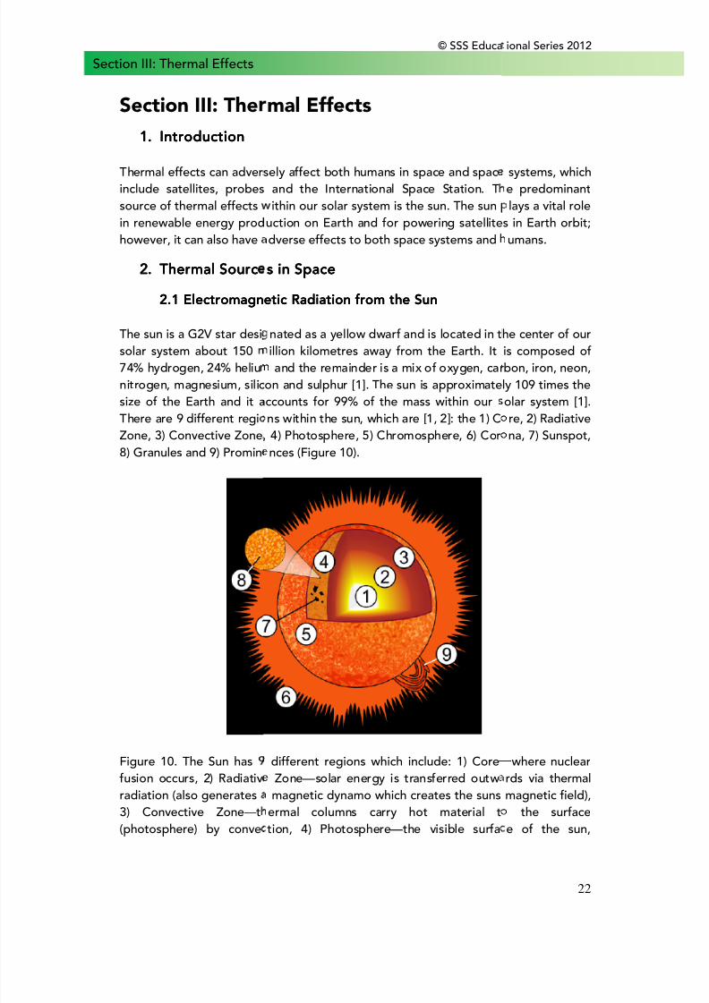
The sun is a G2V star desisolar system about 15074% hydrogen, 24% heliunitrogen, magnesium, silicsize of the Earth and it aThere are 9 different regiZone, 3) Convective Zone,8) Granules and 9) Promin
Figure 10. The Sun hasfusion occurs, 2) Radiativradiation (also generates3) Convective Zone—t(photosphere) by conve
© SSS Educa
mal Effects
sely affect both humans in space and spacand the International Space Station. Tithin our solar system is the sun. The sun
uction on Earth and for powering satellitedverse effects to both space systems and
s in Spaces in Spaces in Spaces in Space
etic Radiation from the Sunetic Radiation from the Sunetic Radiation from the Sunetic Radiation from the Sun
nated as a yellow dwarf and is located in tillion kilometres away from the Earth. Itand the remainder is a mix of oxygen, car
on and sulphur [1]. The sun is approximateccounts for 99% of the mass within ourns within the sun, which are [1, 2]: the 1) C4) Photosphere, 5) Chromosphere, 6) Cornces (Figure 10).
different regions which include: 1) Core Zone—solar energy is transferred outw
magnetic dynamo which creates the sunsermal columns carry hot material ttion, 4) Photosphere—the visible surfa
ional Series 2012
22
systems, whiche predominantlays a vital role
s in Earth orbit;umans.
he center of ouris composed ofbon, iron, neon,ly 109 times theolar system [1].re, 2) Radiativena, 7) Sunspot,
where nuclearrds via thermalmagnetic field),
the surfacee of the sun,
8/10/2019 Space Weather Effects on Space Missions
http://slidepdf.com/reader/full/space-weather-effects-on-space-missions 28/37
© SSS Educational Series 2012
23
Section III: Thermal Effectscomposed of granules 5) Chromosphere—layer above the photosphere 6) Corona—composed of ionised gas (plasma), 7) Sunspot—created by magnetic activity thatinhibits convection, 8) Granules—convection cells of gas and 9) Prominences—loopof plasma that extend from the sun’s surface to the corona, which serve as aprecursor to coronal mass ejections (CMEs)(Source: NASA).
The intense energy that is given off by the sun is fuelled through a fusion reaction inthe core of the sun, which reaches temperatures of up to 13.6 million Kelvin (K) [2].The fusion reaction that occurs in the core is driven by a proton-proton chain inwhich hydrogen is converted into helium (two fused hydrogen atoms) [3]. The massof the fused atom is less than the sum of the two individual hydrogen atoms and thismissing mass is converted to energy through Einstein’s theory of mass-energyequivalence [3]. The excess energy then diffuses through the successive layers of thesun to reach the solar photosphere where it escapes as electromagnetic radiation.
Electromagnetic (EM) radiation exhibits a wave-like characteristic when travellingthrough space and consists of electric and magnetic components, which oscillate inphase perpendicular to each other. EM radiation includes waves of different energiessuch as radiowaves, microwaves, infrared radiation, visible light, ultraviolet (UV)radiation, X-rays and gamma rays, the latter three being the most harmful to humans[4].
The solar energy output from the sun at any given time is 3.846*1026 W (luminosity)of which we receive approximately 1366 W/m2 in the outer Earth’s atmosphere [5].
The change in energy output is governed by an 11 year solar cycle, which causescyclic changes in total solar irradiance resulting in a variance of 1.3W/m2 [4]. Anotherphenomenon known as the Milankovitch cycle plays a more important role in whichthe energy variance perceived by the Earth is dependent on Earth’s position,whether it is at the perihelion or the aphelion. This variation in the orbit results in achange of approximately 25% in the energy that is received in certain areas on Earth[6, 7]. Thus, satellites and the ISS, which are in low Earth orbit (LEO) feel aperceptible change as a result of the solar and Milankovitch cycles.
2222.2 Solar Wind Heating.2 Solar Wind Heating.2 Solar Wind Heating.2 Solar Wind HeatingSolar wind heating is another source of thermal energy throughout the solar system.The solar wind has a slow component and fast component. The slow solar windoriginates from the sun’s equatorial region; it has a temperature of 1,500,000 K andtravels at 400 km/s [8]. The composition of the slow solar wind resembles that of thecorona, which predominantly contains ionised gas [8]. On the other hand, the fastsolar wind travels an order of speed faster, it’s composition is similar to that of thephotosphere (convection cells) and the solar material is released from coronal holes[8].
8/10/2019 Space Weather Effects on Space Missions
http://slidepdf.com/reader/full/space-weather-effects-on-space-missions 29/37
© SSS Educational Series 2012
24
Section III: Thermal EffectsAlthough, the sun releases a stream of electrons and protons that escape due totheir high kinetic energy, these particles are not the primary source of thermalenergy of the solar wind. Overtime, as the high-energy particles released from thesun mix with one another in space, this causes turbulence and the generation ofthermal energy [9]. The stirring of the solar wind produces swirls and eddies whichbreakdown overtime and the thermal energy is dissipated as result of the mixingprocess [9, 10].
3.3.3.3. Thermal EffectsThermal EffectsThermal EffectsThermal Effects
3.3.3.3.1 Governance of Thermal Output from the Sun1 Governance of Thermal Output from the Sun1 Governance of Thermal Output from the Sun1 Governance of Thermal Output from the Sun
Thermal radiation from the sun occurs through the release of visible light andinfrared radiation [11]. This occurs through fusion reactions from the ionised mixtureof hydrogen and helium gas in the sun’s core [11]. As the gas in the sun’s core is atvery high temperatures, thermal collisions between atoms will ionise them resultingin the ejection of electrons that will co-exist with atomic ions [11]. The thermalconductivity of the sun is dependent on the degree of ionisation of the atoms.Ionisation can be determined using the Saha ionisation equation [12], however thisequation is ideally applied in cases when the system is in equilibrium. As the sun isnot entirely in equilibrium since the solar chromosphere, corona and prominences arenot in radiative equilibrium (the heat generated from fusion is entirely transferred aselectromagnetic radiation from the sun into space), the ionisation capacity alone isnot enough to describe the thermal conductivity of the sun [13]. An improvedmethod to describe the conductivity of the sun takes into account the density of thevarious particles, the temperature and the ionisation energy of the atoms [13].Furthermore, in the presence of a strong magnetic field, heat conduction by chargedparticles across lines of force is greatly reduced and as a result the thermalconductivity is determined mainly by the remaining neutral particles (unionised formof He and H) [13]. In addition, heat conduction by neutral atoms plays a key rolewhen the system deviates from thermodynamic equilibrium in solar prominences andthe chromosphere. In these regions the electron temperature can exceed the localradiation temperature and as result ionisation is greatly reduced [13].
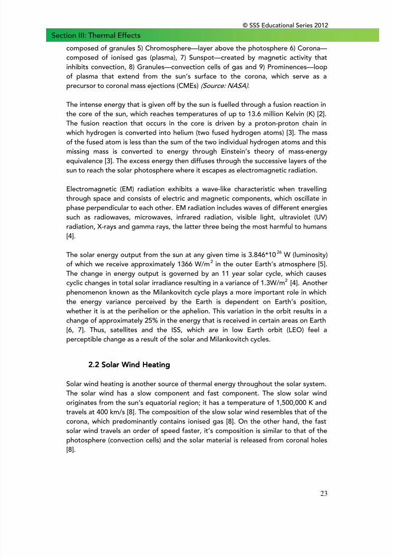
The thermal conductivity is determined as follows [13]:
Figure 11. Thermal Conductivity from the Sun. Whereλ 1=thermal conductivity,Γ 1=conductivity of neutral particles, T=temperature, N=electron density,Γ 2=conductivity of positively charged particles,Γ 3=conductivity of negatively
charged particles
8/10/2019 Space Weather Effects on Space Missions
http://slidepdf.com/reader/full/space-weather-effects-on-space-missions 30/37
© SSS Educational Series 2012
25
Section III: Thermal EffectsThe thermal conductivity is determined using the equation in Figure 1, whichrequires conductivity of neutral and charged particles, in addition to the temperatureof the chromosphere, electron density and the strength of the sun’s magnetic field.As the sun has a large magnetic field, the conductivity of the neutral atoms isprimarily what governs the thermal conductivity of the sun since the term thataccounts for the conductivity of positively and negatively charged atoms approacheszero, {(8.82*1024) * (TN22/H2) * (Γ 2 +Γ 3) = 0}.
4.4.4.4. Examples of Thermal EffectsExamples of Thermal EffectsExamples of Thermal EffectsExamples of Thermal Effects
4444.1 Satellites.1 Satellites.1 Satellites.1 Satellites
The ISS and all other satellites in space make use of the abundant solar energy fromthe sun. However, during the release of solar flares and coronal mass ejections, thereis an abundant amount of thermal energy that is released and a milieu of energeticparticles that adversely affect the ISS and its inhabitants.
A study by Bekhti et al. showed that the battery system on board a nano-satelliteoperating for about two years was sub-nominal until the satellite was yawed 180°,resulting in a change of the battery pack position in the satellite reference frame(and relative to the sun). This caused the temperature to be restored to the nominallevel and the cell performance increased appreciably as determined through thecharging/discharging process [14].
The ISS is also affected by thermal energy from the sun resulting in increased cabintemperatures [15].
4444.2 Launch Vehicles.2 Launch Vehicles.2 Launch Vehicles.2 Launch Vehicles
Spacecrafts are subjected to extreme temperatures as a result of direct sunlight orshade and to regulate these extreme temperatures, a thermal protection system(TPS) is required.
4444.3 Humans.3 Humans.3 Humans.3 Humans
During extra-vehicular activity, humans in space are exposed to extremetemperatures as a result of the sun and as such also require a protective thermalsystem.
8/10/2019 Space Weather Effects on Space Missions
http://slidepdf.com/reader/full/space-weather-effects-on-space-missions 31/37
© SSS Educational Series 2012
26
Section III: Thermal Effects5.5.5.5. Mitigation of Thermal EffectsMitigation of Thermal EffectsMitigation of Thermal EffectsMitigation of Thermal Effects
5555.1 Satellites.1 Satellites.1 Satellites.1 Satellites
In order to regulate the temperature of satellites, optical solar reflectors arecommonly used which are composed of quartz or Teflon followed by a metal layer(silver). The two layers together create a “cold material” that allows solar light tofreely pass through the quartz outer layer and then reflect off of the metal layerresulting in decreased absorption by critical components on the satellite [16]. Asspace is a vacuum, cooling satellites can be a difficult task as many of the coolingsystems we use on Earth utilise convection, which would necessitate the use ofairflow. If the satellite undergoes large temperature fluctuations as it could beexposed to direct sunlight or shade, these successive changes in temperature causethe protective coatings on the satellite to breakdown. Overtime, the satellite can
then lose its capacity to ensure optimal power generation and thus it is important toconsider the orientation of the satellite prior to orbit insertion. By changing thepitch, yaw or roll of the satellite, this alters the angle of incidence at which thesunlight hits the satellite and in the long term it would have a large effect on thepower generation capacity [14]. As a result, orientation changes that are expected tooccur throughout the satellites lifetime should be rigorously assessed and modelledprior to orbit insertion to minimise any insidious thermal effects.
On the ISS, there is a thermal control system (TCS), which is used to regulate heatfluctuations [15, 17-19]. The TCS is responsible for: 1) collecting, distributing and
rejecting heat, 2) meeting intra/extra-vehicular touch temperatures, 3) precludingcondensation and 4) maintaining structural interface temperatures [15]. There aretwo parts to the TCS, which include the Internal Active Thermal Control System(IACTS)—a water based system that works with the External Active Control System(EACTS), which is an ammonia based system [17]. The TCS system is comprised ofboth active and passive conditioning measures for maintaining thermal control. Thepassive system works by using thermal coatings, cold-plates and multilayer insulationto keep hardware within the specified temperature limits [17]. In contrast, the activesystem uses: 1) externally mounted water/ammonia heat exchangers, 2) water pumpsfor providing moderate and low temperature coolant to racks and cold-platedhardware, 3) moderate and low temperature cross strapping for failure redundancyand 4) rack flow control valves to provide additional temperature control at the racks[17]. In addition, there is also an external thermal control system to cool thehardware associated with the photovoltaic arrays. This includes the batteries, batterydischarging/charging units, DC converter units and DC switching units [17]. Theimplementation of the TCS on the ISS allows for the successful maintenance ofthermal energy fluctuations that occur as a result of exposure or a lack of exposureto the sun.
8/10/2019 Space Weather Effects on Space Missions
http://slidepdf.com/reader/full/space-weather-effects-on-space-missions 32/37
© SSS Educational Series 2012
27
Section III: Thermal Effects5555.2 Launch Vehicles.2 Launch Vehicles.2 Launch Vehicles.2 Launch Vehicles
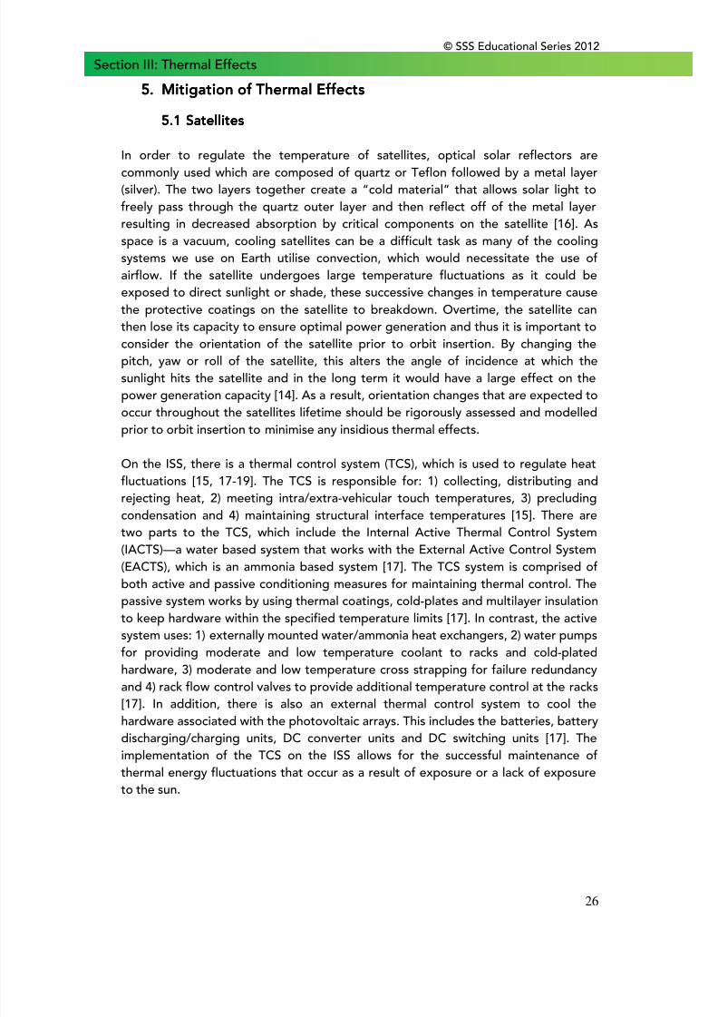
The shuttle developed by United States National Aeronautics and SpaceAdministration (NASA) and recently retired, had a thermal control system for twopurposes, to protect it from the heat during re-entry and against the largefluctuations of thermal energy while in orbit. As the shuttle’s base structure wasconstructed from aluminium it was not able to withstand temperatures over 175oCwithout a thermal protective system (TPS) [20]. The outer skin of the shuttle wascomposed of seven different materials that are found on different regions of theshuttle [21].
On the shuttle the TPS was divided into a tile based and non-tile based system.There are four different tile types, all of which are very poor conductors in order toprevent heat transfer [20, 22]. The four tile types include high-temperature reusable
surface insulation (HRSI), fibrous refractory composite insulation tiles (FRCI),toughened unipiece fibrous insulation (TUFI) and low-temperature reusable surfaceinsulation (LRSI) [21]. The non-tile materials used on the shuttle as part of the TPSincluded flexible insulation blanket (FIB), reinforced carbon-carbon (RCC), Nomex feltreusable surface insulation (FRSI) and gap fillers [21].
On the shuttle, the HRSI tiles were composed of high purity silica fibers and coverthe under-side which are able to withstand temperatures up to 1260oC [21]. Duringsubsequent repairs of the shuttle, the HRSI tiles were replaced with either FRCI orTUFI tiles, both of which provided increased strength, durability and resistance to
cracking. LRSI tiles were originally used on the sides of the craft and the tail wingwhich have been retrofitted with flexible insulation blankets (FIB) composed of awhite low density fibrous silica material that requires less maintenance than theearlier LRSI tiles [21]. The wings of shuttle are lined with reinforced carbon-carbon—acomposite material made from graphite rayon cloth and impregnated phenolic resin[21]. These panels along the wing are between 6 to 13 mm thick and can withstandtemperatures up to 1510oC [21]. The upper surface and aft fuselage of the shuttlewere coated with FRSI, a white flexible fabric that could withstand temperatures upto 371oC [21]. Lastly, the gap fillers, composed of alumina fibers, were placed atseveral locations throughout the shuttle (leading edge of foreward fuselage, nosecaps, windshields, side hatch, wings, vertical stabiliser, rudder, speed rake, bodyflaps and on the heat shield around the main engines) to minimise heating bypreventing the formation of vortices in areas where surface pressure gradients wouldresult in a cross-flow of air within the gaps [21].
8/10/2019 Space Weather Effects on Space Missions
http://slidepdf.com/reader/full/space-weather-effects-on-space-missions 33/37
© SSS Educational Series 2012
28
Section III: Thermal Effects
Figure 12. Shuttle Thermal Protection System(Source: NASA).
In addition, at the NASA Ames Research Center in Moffett Field, California, there are
additional studies ongoing to develop Ultra High Temperature Ceramics (UHTC) thatcan be used on future re-entry vehicles [20].
The Russian Federal Space Agency (ROSCOSMOS) also has a launch vehicle knownas Soyuz-TMA. This Soyuz launch vehicle is a segmented craft consisting of anforward orbital module (holds crew), a center descent module and an aft servicemodule (contains instruments and engines) [23, 24]. The exterior thermal protectionon a Soyuz-TMA craft involves service module radiators [25], along with a multi-layervacuum-screen thermal insulation [24]. The descent module carries eight thermalblankets held by the apex and base rings which are released when the modules areseparated for re-entry [25].
5555.3 Humans.3 Humans.3 Humans.3 Humans
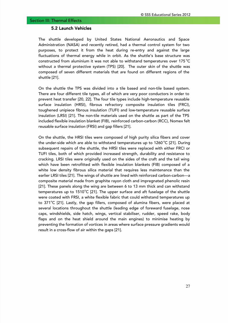
Due to extreme thermal conditions an astronaut will face during extra-vehicularactivity (EVA), an extravehicular mobility unit is required to withstand the harshconditions. The American spacesuit—Enhanced Extravehicular Mobility Unit (EMU) is jointly developed by Hamilton Sundstrand, International Latex Corporation Doverand NASA [26]. The suit is primarily white, which allows it to reflect a significantportion of the thermal energy from the sun and is able to sustain temperatures from-156oC to 121oC [26]. The spacesuit consists of a hard upper torso assembly [27],
8/10/2019 Space Weather Effects on Space Missions
http://slidepdf.com/reader/full/space-weather-effects-on-space-missions 34/37
© SSS Educational Series 2012
29
Section III: Thermal Effectsprimary life support system and a lower torso assembly [27]. Astronauts have to weara thermal control undergarment and then the liquid cooling and ventilation garment,the latter of which incorporates tubing through which chilled water is pumped fortemperature regulation and ventilation tubes for waste gas removal [27]. This is thenfollowed by putting on the lower torso assembly [27]. The enhanced EMU cansupport an astronaut for 8.5 hours with a 30-minute reserve in case there is a failurewith the primary system.
Figure 13. The Enhanced Extra-vehicular Mobility Unit(Source: NASA).
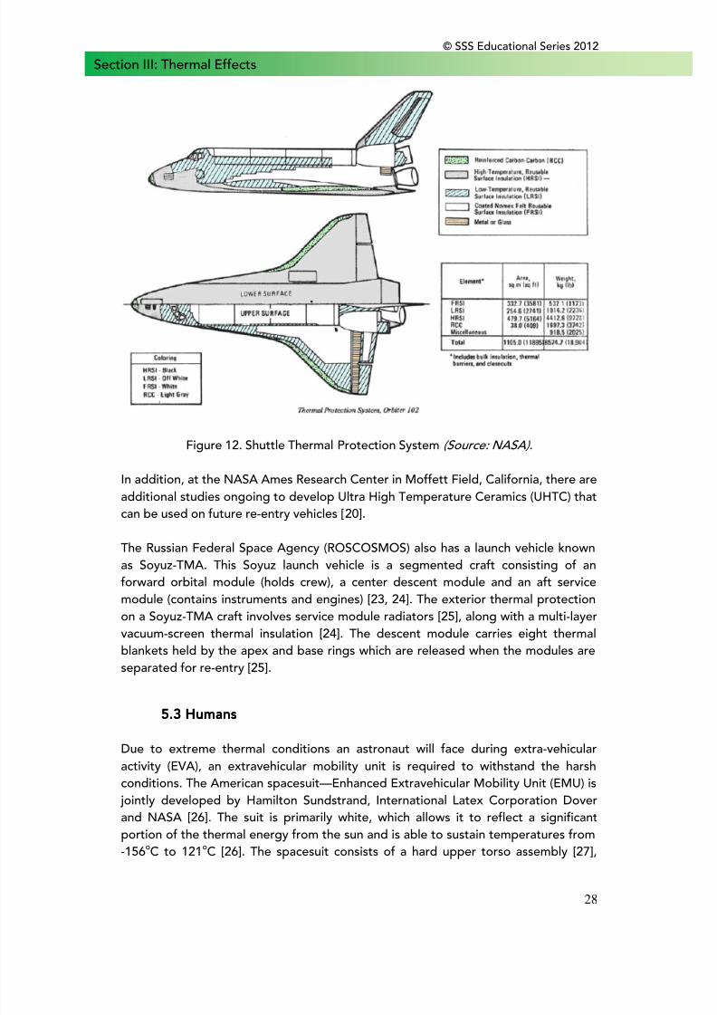
The other spacesuit that is commonly used on the ISS and for EVA’s is the Russian
Orlan-MK suit developed by NPP Zvezda [28]. It has primary life support time of 7hours and weighs approximately twice as much as United States EMU. Although, theweight is twice as much, the Orlan suit is a one-piece semi-rigid model that requiresonly 5 minutes of preparation time as it has a rear hatch entry [28]. The Orlan-MK canalso withstand extreme temperatures, radiation and micrometeorites equivalent tothat of the EMU [29].
Figure 14. Orlan-M Spacesuit(Source: Russian Space Federation).
8/10/2019 Space Weather Effects on Space Missions
http://slidepdf.com/reader/full/space-weather-effects-on-space-missions 35/37
© SSS Educational Series 2012
30
Section III: Thermal Effects6.6.6.6. ReferencesReferencesReferencesReferences
[1] Williams, D. Sun Fact Sheet. 2004 [cited 2010 May 12]; Available from:http://nssdc.gsfc.nasa.gov/planetary/factsheet/sunfact.html.
[2] Eddy, J.A. A New Sun: The Solar Results from Skylab. 1979 [cited 2011 May 7];Available from:http://history.nasa.gov/SP-402/contents.htm.
[3] Smirnov, B.M., Plasma Processes and Plasma Kinetics. Electrophoresis,2007(7883744296578191625related:CRGO-aqvaG0J).
[4] Maalouf, M., M. Durante, and N. Foray, Biological effects of space radiation onhuman cells: history, advances and outcomes. Journal of radiation research, 2011.52(21436608): p. 126-46.
[5] Basu, S., Helioseismology and solar abundances. Physics Reports,2008(3553695456915610782related:ntxflTBDUTEJ).
[6] Doormann, V., SOLAR SYSTEM GEOMETRIES AND TERRESTRIAL CLIMATE.volker-doormann.org, 2010(related:8eIJdxXsVPYJ).
[7] Clark, S., Sun's fickle heart may leave us cold. New Scientist, 2007.
[8] Hathaway, D. Solar Physics. 2007 [cited 2011 May 14]; Available from:http://solarscience.msfc.nasa.gov/feature1.shtml.
[9] Hassler, D.M., et al., Solar wind outflow and the chromospheric magneticnetwork. Science, 1999(3889806379195337319related:Z4r89Epe-zUJ).
[10] Sahraoui, F., M.L. Goldstein, and P. Robert, A, Evidence of a cascade anddissipation of solar-wind turbulence at the electron gyroscale. Physical review letters,2009(18168762412411035511related:d5864CZpJPwJ).
[11] Broggini, C., Nuclear processes at solar energy. Arxiv preprint astro-ph,2003(8677295430675503475related:c5mITDjya3gJ).
[12] Brokaw, R.S., Approximate formulas for the viscosity and thermal conductivity ofgas mixtures. The Journal of Chemical Physics, 1958 (10584108522416325608related:6EPPxp9O4pIJ).
[13] Orrall, F.Q., The Coefficient of Thermal Conductivity in the Sun's Atmosphere.The Astrophysical Journal, 1961(6645977447091387690related:Kr0jt0ZBO1wJ).
[14] Bekhti‚ M., Temperature effects on satellite power systems performance.‚European conference of systems, 2010(related:IO8F2VPSRr0J).
8/10/2019 Space Weather Effects on Space Missions
http://slidepdf.com/reader/full/space-weather-effects-on-space-missions 36/37
© SSS Educational Series 2012
31
Section III: Thermal Effects
[15] Morrison‚ R.H., ISS Internal Active Thermal Control System (IATCS) CoolantRemediation Project-2006 Update. papers.sae.org, 2006.
[16] Ichino, T. and S. Sasaki, Development of high‚Äêperformance flexible opticalsolar reflectors., and Communications in Japan, 1986.
[17] Reysa, R., The International Space Station ECLS and thermal control systems-Overview., Space Environmental Control Systems, 1997.
[18] Benardini, J., J. Ballinger, and R.L. Crawford, International space station internalactive thermal control system: An initial assessment of the microbial communitieswithin fluid from ground support and flight., SAE transactions, 2005.
[19] Rector, T. and J. Steele, ISS IATCS Coolant Loop Biocide Implementation.papers.sae.org, 2008.
[20] Dunbar, B. Thermal Protection System (TPS) and Materials. 2008 [cited 2011May 9]; Available from:http://www.nasa.gov/centers/ames/research/humaninspace/humansinspace-thermalprotectionsystem.html.
[21] Kennedy, K.J.a.G., Space Shuttle Operator's Manual. 1982: Ballantine Books.
[22] Information Summaries: Countdown! NASA Launch Vehicles and Facilites (NASAPMS 018-B). 1991.
[23] Soyuz spacecraft: Made to measure. 2004 [cited 2011 May 7]; Available from:http://www.esa.int/esaMI/Delta_Mission/SEMWWK57ESD_0.html.
[24] Zak, A. Spacecraft: Manned: Soyuz. 2001 [cited 2011 May 9]; Available from:http://www.russianspaceweb.com/soyuz.html.
[25] Association, N.S.T. Rocket and Space Technology: Soyuz. 2001; Available from:http://www.braeunig.us/space/specs/soyuz.htm.
[26] McMann, K.T.a.H., US Spacesuits. 2006, Chichester: Praxis Publishing Ltd.
[27] Donning the Spacesuit. 2002 [cited 2011 May 14]; Available from:http://www.asc-csa.gc.ca/eng/educators/resources/spacesuit-donning.asp#tphp.
[28] Skoog, I.A.a.I., Russian Spacesuits. 2003, Chichester: Praxis Publishing Ltd.
[29] McHale, S. Orlan-MK. 2010 [cited 2011 May 15]; Available from:http://suzymchale.com/ruspace/orlanmk.html.
8/10/2019 Space Weather Effects on Space Missions
http://slidepdf.com/reader/full/space-weather-effects-on-space-missions 37/37
Schwarzenbergplatz 6
Vienna A-1030
AUSTRIA