Embed Size (px)
Citation preview

Space Shuttle Payloads Support Capability
Item Type text; Proceedings
Authors Torres, Frank
Publisher International Foundation for Telemetering
Journal International Telemetering Conference Proceedings
Rights Copyright © International Foundation for Telemetering
Download date 28/05/2018 03:26:59
Link to Item http://hdl.handle.net/10150/613928
SPACE SHUTTLE PAYLOADS SUPPORT CAPABILITY
Frank TorresSupervisor, STS Payload Integration
Electronic Systems, Space Systems GroupRockwell International
12214 Lakewood Blvd, Downey, California
ABSTRACT
The NASA/Rockwell Space Shuttle with its highly versatile avionics and electricalprovisions for use by the Shuttle payloads will provide an efficient system for futurenational space program activities and space program activities from foreign countries. Thispaper summarizes the avionics and electrical payload capabilities and interfacecharacteristics. It includes a description of the command and data systems interface, thecaution and warning system interface, and the aft flight deck accommodations; theelectrical power distribution system; and the standard mixed cargo harness.
INTRODUCTION
The primary mission for the Space Shuttle is the delivery of payloads to earth orbit. Inorbit, the Space Shuttle has the capability to carry out missions unique to the spaceprogram: to deploy payloads whose destination is high-altitude orbits; to retrieve payloadsfrom orbit for reuse; to service or refurbish satellites in space; and to operate spacelaboratories in orbit. To accomplish these objectives, the Shuttle orbiter provides anavionic system that interfaces with payloads through the payload and mission specialiststations by means of hardwired controls and displays when the payloads are attached tothe orbiter and through a radio link when the payloads are detached. The capability andinterface characteristics of the avionics system that has been designed in support ofpayload operations and described in detail in NASA/JSC 07700, Volume XIV, aresummarized in this paper.
The standard avionics provisions for payloads include communication, command, and datamanagement interfaces with attached and detached payloads and electrical power andcaution/warning interfaces for attached payloads. A functional block diagram of thesestandard avionics provisions is shown in Figure 1.
Orbiter transmitters, receivers, and signal structure are compatible with the establishedcharacteristics of NASA’s space tracking and data network (STDN) and tracking and datarelay satellite (TDRS), and the Air Force space-ground link subsystem (SGLS). Theorbiter is equipped to communicate with ground stations, TDR satellites, and detachedpayloads at S-band frequencies and with the TDRS at Ku-band frequencies.
PAYLOAD COMMAND SYSTEM INTERFACES
Commands to attached or detached payloads can be forwarded from the ground orgenerated on-board. A block diagram of the command system interface is shown inFigure 2.
Payload Interrogator
The commands to detached payloads are via the payload interrogator, whose transmitter iscapable of operating in three prime modes: STDN, deep space netork (DSN), and DOD.The transmit frequency channels available are as follows:
� STDN compatible payload - 808 channels from 2025.833333 to 2118.722328 MHz in115.104 kHz increments (221/240 transmit/receive ratio).
� DSN compatible payloads - 29 channels from 2110.243056 to 2119.792438 MHz in341.049 kHz increments (221/240 transmit/receive ratio).
� SGLS compatible payloads - 20 channels from 1763.721 to 1839.795 MRz in 4.004MHz increments (205/256 transmit/receive ratio).
In the STDN and DSN modes, the interrogator accepts a 16-kHz subcarrier (PSK-modulated by command signals ranging from 125/16 to 2000 bps rate) and phasemodulates the selected S-band carrier for RF transmission to the detached payload. In theDOD mode, the interrogator accepts a 65 (“S”), or 76 kHz (“0”), or 95 kHz (“1”)subcarrier, amplitude-modulated by a 1-kHz or 2-kHz triangular wave from the user-provided signal processor in the payload station. The accepted signal phase modulates theselected RF carrier.
Payload Signal Processor (PSP)
In the STDN and DSN modes, the baseband signal is available to attached payloads viathe PSP, which offers five differential outputs. Each output provides a 4 volt peak-to-peak(line-to-line), 16-kHz sinewave, PSK-modulated by the command data at data rates

ranging from 125/12 to 2000 bps. The data waveform can be any one of the following:Bi-N-L, -M, or -S; or NRZ-L, -M, or -S.
Multiplexer/Demultiplexer (MDM)
Serial digital and discrete commands are provided by the MDM. These commands canalso be forwarded from the ground stations or generated on-board initiated via thekeyboard. In the serial mode, the MDM command signal consists of a Manchester IIbiphase signal at a 1-mps burst rate. The true logic level is a nominal +4.5 Vdc, and thefalse logic level is a nominal -4.5 Vdc. The command signal channel includes word,message-in, message-out discretes, whose logic levels are nominally +3.5 Vdc and -3.5 Vdc for the true and false logic levels. The command message can include up to 3216-bit data words. In the discrete output mode the MDM provides low-level and high-leveldiscretes whose true/false logic levels are nominally +5/0 Vdc and +28/0 Vdc. Thirty-sixhigh-level discretes (DOH) and thirty-two low-level discretes (DOL) are available.
Data Bus
For payloads requiring a greater number of commands, a data bus stub is provided toaccommodate the installation of a payload-provided MDM.
Standard Switch Panel
Hardwired commands are provided by the standard switch panel (Figure 3) and the C3A5panel located in the cockpit center console.
Ku-Band Signal Processor
The Ku-band signal processor provides the capability to forward 128 kbps of NRZ-L dataplus clock. The true and false logic levels for this interface are +5 Vdc and -5 Vdc.
PAYLOAD DATA SYSTEM INTERFACE
The Shuttle orbiter avionics provides the capability to process payload data on-board,transmit data to the ground stations in real time, or record the data for later data dump toground stations. A block diagram of the payload data system interfaces is shown inFigure 4.
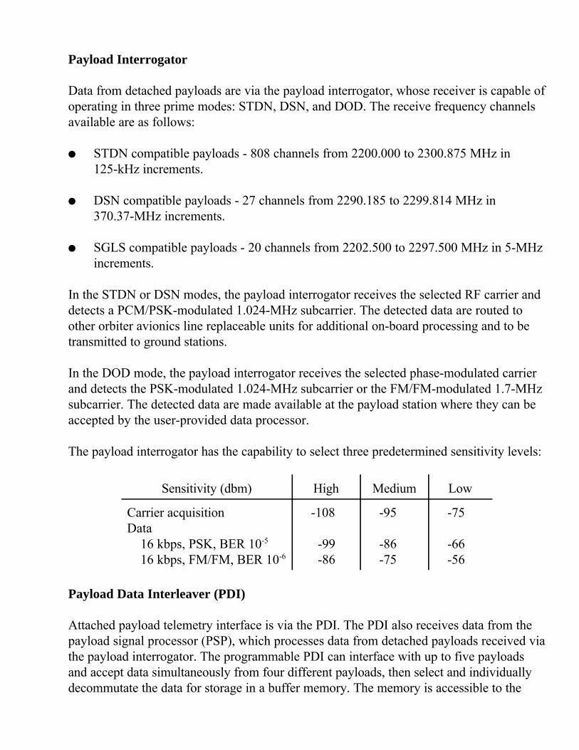
Payload Interrogator
Data from detached payloads are via the payload interrogator, whose receiver is capable ofoperating in three prime modes: STDN, DSN, and DOD. The receive frequency channelsavailable are as follows:
� STDN compatible payloads - 808 channels from 2200.000 to 2300.875 MHz in125-kHz increments.
� DSN compatible payloads - 27 channels from 2290.185 to 2299.814 MHz in370.37-MHz increments.
� SGLS compatible payloads - 20 channels from 2202.500 to 2297.500 MHz in 5-MHzincrements.
In the STDN or DSN modes, the payload interrogator receives the selected RF carrier anddetects a PCM/PSK-modulated 1.024-MHz subcarrier. The detected data are routed toother orbiter avionics line replaceable units for additional on-board processing and to betransmitted to ground stations.
In the DOD mode, the payload interrogator receives the selected phase-modulated carrierand detects the PSK-modulated 1.024-MHz subcarrier or the FM/FM-modulated 1.7-MHzsubcarrier. The detected data are made available at the payload station where they can beaccepted by the user-provided data processor.
The payload interrogator has the capability to select three predetermined sensitivity levels:
Sensitivity (dbm) High Medium Low
Carrier acquisitionData
16 kbps, PSK, BER 10-5
16 kbps, FM/FM, BER 10-6
-108
-99 -86
-95
-86-75
-75
-66-56
Payload Data Interleaver (PDI)
Attached payload telemetry interface is via the PDI. The PDI also receives data from thepayload signal processor (PSP), which processes data from detached payloads received viathe payload interrogator. The programmable PDI can interface with up to five payloadsand accept data simultaneously from four different payloads, then select and individuallydecommutate the data for storage in a buffer memory. The memory is accessible to the
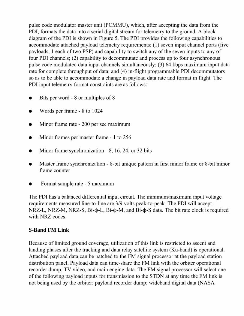
pulse code modulator master unit (PCMMU), which, after accepting the data from thePDI, formats the data into a serial digital stream for telemetry to the ground. A blockdiagram of the PDI is shown in Figure 5. The PDI provides the following capabilities toaccommodate attached payload telemetry requirements: (1) seven input channel ports (fivepayloads, 1 each of two PSP) and capability to switch any of the seven inputs to any offour PDI channels; (2) capability to decommutate and process up to four asynchronouspulse code modulated data input channels simultaneously; (3) 64 kbps maximum input datarate for complete throughput of data; and (4) in-flight programmable PDI decommutatorsso as to be able to accommodate a change in payload data rate and format in flight. ThePDI input telemetry format constraints are as follows:
� Bits per word - 8 or multiples of 8
� Words per frame - 8 to 1024
� Minor frame rate - 200 per sec maximum
� Minor frames per master frame - 1 to 256
� Minor frame synchronization - 8, 16, 24, or 32 bits
� Master frame synchronization - 8-bit unique pattern in first minor frame or 8-bit minorframe counter
� Format sample rate - 5 maximum
The PDI has a balanced differential input circuit. The minimum/maximum input voltagerequirements measured line-to-line are 3/9 volts peak-to-peak. The PDI will acceptNRZ-L, NRZ-M, NRZ-S, Bi-N-L, Bi-N-M, and Bi-N-S data. The bit rate clock is requiredwith NRZ codes.
S-Band FM Link
Because of limited ground coverage, utilization of this link is restricted to ascent andlanding phases after the tracking and data relay satellite system (Ku-band) is operational.Attached payload data can be patched to the FM signal processor at the payload stationdistribution panel. Payload data can time-share the FM link with the orbiter operationalrecorder dump, TV video, and main engine data. The FM signal processor will select oneof the following payload inputs for transmission to the STDN at any time the FM link isnot being used by the orbiter: payload recorder dump; wideband digital data (NASA
payloads), 200 bps to 5 mbps; wideband analog data (NASA payloads), 300 Hz to 4 MHz;and digital data (DOD payloads), 250 bps to 250 kbps.
The FM signal processor has balanced differential input circuits. The digital data (DOD)channel will accept either biphase NRZ data. The input voltage requirement is 1 volt peak-to-peak. The digital data wideband channel receives Bi-N-L or NRZ-L data (Bi-N-L islimited to 2 mbps). The input voltage requirement is 5 volts peak-to-peak. The analog datachannel input voltage requirement is 1 volt peak-to-peak.
Ku-Band Link
On orbit, the Ku-band system provides near continuous ground coverage. Attachedpayload data can be patched to the Ku-band signal processor at the payload stationdistribution panel. For downlink, the Ku-band system operates in two modes, quadraturephase shift key (QRSK, Mode 1) and FM (Mode 2), with three channels of input data ineach mode. The Ku-band communication system is a combined system with therendezvous radar. The system cannot be used in both modes at the same time. Ku-bandservice is provided only when the payload bay doors are open.
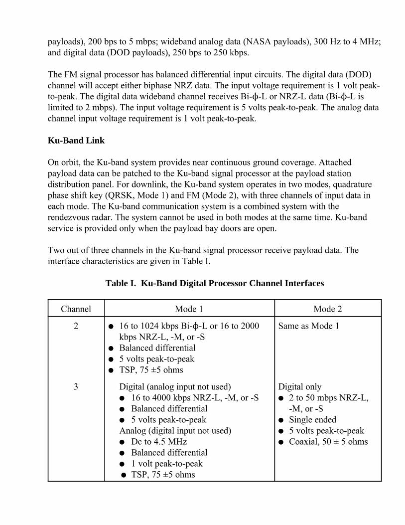
Two out of three channels in the Ku-band signal processor receive payload data. Theinterface characteristics are given in Table I.
Table I. Ku-Band Digital Processor Channel Interfaces
Channel Mode 1 Mode 2
2 � 16 to 1024 kbps Bi-N-L or 16 to 2000kbps NRZ-L, -M, or -S
� Balanced differential� 5 volts peak-to-peak� TSP, 75 ±5 ohms
Same as Mode 1
3 Digital (analog input not used)� 16 to 4000 kbps NRZ-L, -M, or -S� Balanced differential� 5 volts peak-to-peakAnalog (digital input not used)� Dc to 4.5 MHz� Balanced differential� 1 volt peak-to-peak � TSP, 75 ±5 ohms
Digital only� 2 to 50 mbps NRZ-L,
-M, or -S� Single ended� 5 volts peak-to-peak� Coaxial, 50 ± 5 ohms
In Channel 2, the payload timeshares the Ku-band system with the operational recorderdump, and the payload recorder dump. Mission planning is required to ensure that use ofthis interface is properly coordinated. Likewise in Channel 3, the Ku-band system istimeshared by the payload that is sending digital data, the payload that is sending analogdata, and the orbiter TV downlink.
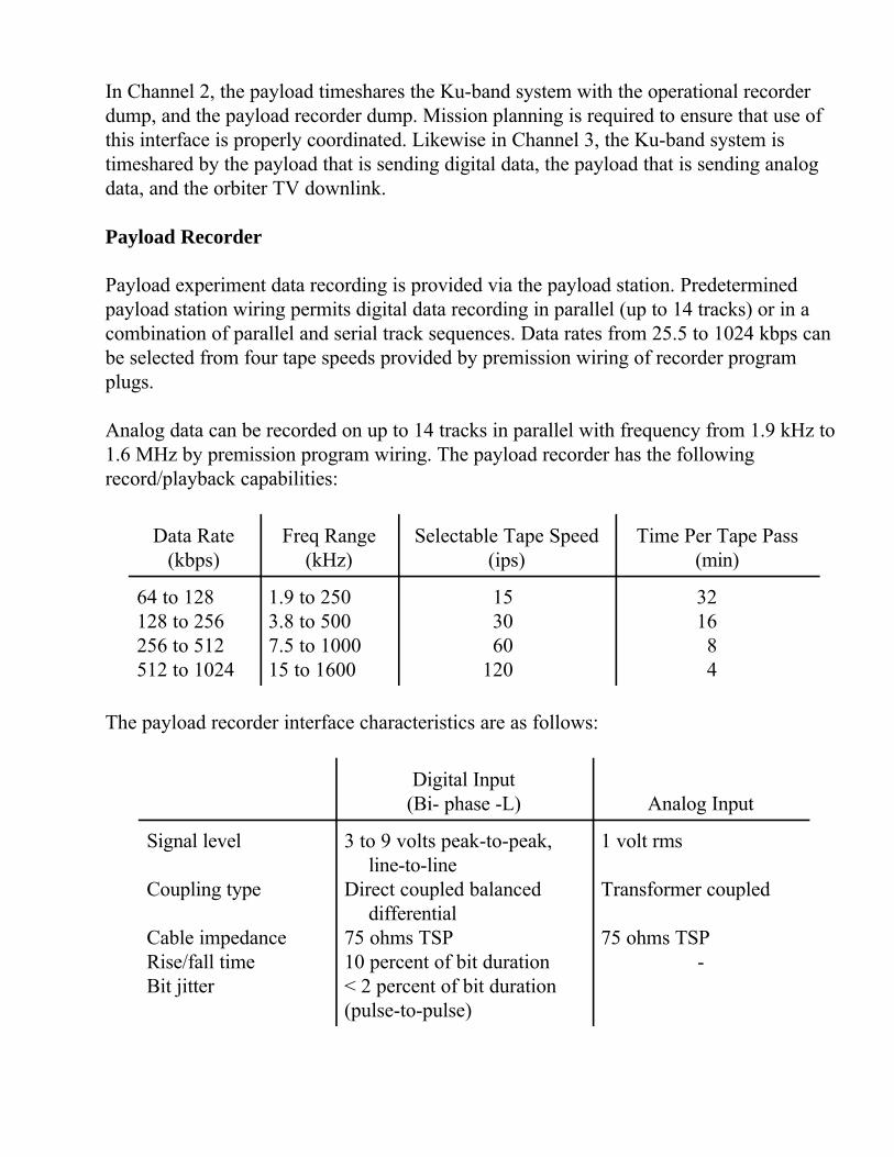
Payload Recorder
Payload experiment data recording is provided via the payload station. Predeterminedpayload station wiring permits digital data recording in parallel (up to 14 tracks) or in acombination of parallel and serial track sequences. Data rates from 25.5 to 1024 kbps canbe selected from four tape speeds provided by premission wiring of recorder programplugs.
Analog data can be recorded on up to 14 tracks in parallel with frequency from 1.9 kHz to1.6 MHz by premission program wiring. The payload recorder has the followingrecord/playback capabilities:
Data Rate(kbps)
Freq Range(kHz)
Selectable Tape Speed(ips)
Time Per Tape Pass(min)
64 to 128128 to 256256 to 512512 to 1024
1.9 to 2503.8 to 5007.5 to 100015 to 1600
153060
120
321684
The payload recorder interface characteristics are as follows:
Digital Input(Bi- phase -L) Analog Input
Signal level
Coupling type
Cable impedanceRise/fall timeBit jitter
3 to 9 volts peak-to-peak,line-to-line
Direct coupled balanceddifferential
75 ohms TSP10 percent of bit duration< 2 percent of bit duration(pulse-to-pulse)
1 volt rms
Transformer coupled
75 ohms TSP-
Multiplexer/Demultiplexer (MDM) Interface
The MDM is capable of receiving payload data in the form of 5-volt discretes (DIL), 0 to5-volt differential analog inputs (AID), and serial data (up to 32 16-bit words) at a 1-mbpsburst rate. Payload downlink telemetry originating at this interface may be substituted forPDI downlink data on orbit. Thirty-two DIL’s, eight AID’s, and four serial channels areavailable to the user as a standard service. The interface characteristics for these inputs areas follows:
� DIL’s- Logic levels: 5 Vdc, True; 0 Vdc, False- TSP, 75 ohms
� AID’s- Signal amplitude: differential +5.11 to -5.12 Vdc- TSP, 75 ohms
� Serial digital channel (4 lines)- Manchester II Bi-N at 1 mps (burst)- Data line true/false logic levels (nominal): +4.5 Vdc/-4.5 Vdc- Word, message-in, message-out true/false logic levels (nominal): +3.5 Vdc/-3.5 Vdc
Master Timing Unit (MTU)
The MTU provides Greenwich Mean Time (GMT) and Mission Elapsed Time (MET) timecode outputs in IRIG-B/modified code formats to payloads as a standard service. Thevoltage level of these signals is nominally 5 volts peak-to-peak. A 75-ohm TSP cable isused.
Payload Caution and Warning System Interface
Orbiter caution and warning is defined to include emergency, warning, and cautionparameters. In the case of manned payloads, two identified orbiter emergency parametersrequire instinctive, immediate crew corrective action. They are fire/smoke and loss ofcabin pressure. The caution and warning electronics unit will receive up to five hardwired-sensor dedicated payload warning parameters. The MDM will receive a total of 50software-controlled payload caution inputs. They consist of 25 5-volt discretes and 25 0 to5-volt differential analog inputs.
Safing commands can be generated by use of the five redundant switches on the C3A5panel located at the commander/pilot center station. Use of these switches requires wire

patching at the payload station distribution panel. The payload MDM’s provide up to 36safing commands consisting of 28-volt discretes. The commands can be initiated on boardvia the keyboard or on the ground via the uplink/forward link. Eighteen of the 36 safingcommands require wire patching at the mission station distribution panel.
Figure 6 shows a block diagram of the payload caution and warning system interface. Theinterfaces are keyed to the caution and warning signal characteristics in the following list:
1. Dedicated caution and warning electronics unit� 5 signal paths� Any combination of 5-Vdc discretes, 28-Vdc discretes, 0 to 5-V analog
2. MDM caution and warning inputs - direct to MDM� 12 analog differential input (AID) signal paths� Voltage range: +5.12 Vdc to -5.12 Vdc� 13 discrete input: low level (DIL) signal paths� Logic levels: True, +5 ±1.0 Vdc; False, 0 ±0.5 Vdc
3. MDM caution and warning inputs: via mission station� 13 analog differential input (AID) signal paths� Voltage range: +5.12 Vdc to -5.12 Vdc� 12 discrete input: low level (DIL) signal paths� Logic levels: True, +5 ±1.0 Vdc; False, 0 ±0.5 Vdc
4. MDM safing commands: direct from MDM� 20 discrete outputs: high-level (DOH) signal paths� Logic levels: True, +19.5 to +32 Vdc; False, 0 to 3 Vdc
5. MDM safing commands: via mission station� 18 discrete outputs: high-level (DOH) signal paths� Logic levels: True, +19.5 to +32 Vdc; False, 0 to 3 Vdc
6. C3A5 panel. switches� 5 redundant safing command signals consisting of switch closures
7. )P/)T to Panel R13 A3� One differential analog signal� Voltage range: 0 to 5 Vdc
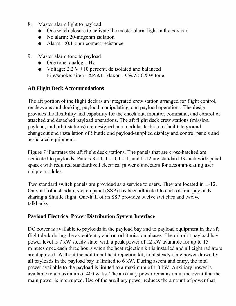
8. Master alarm light to payload� One witch closure to activate the master alarm light in the payload� No alarm: 20-megohm isolation� Alarm: #0.1-ohm contact resistance
9. Master alarm tone to payload� One tone: analog 1 Hz� Voltage: 2.2 V ±10 percent, dc isolated and balanced
Fire/smoke: siren - )P/)T: klaxon - C&W: C&W tone
Aft Flight Deck Accommodations
The aft portion of the flight deck is an integrated crew station arranged for flight control,rendezvous and docking, payload manipulating, and payload operations. The designprovides the flexibility and capability for the check out, monitor, command, and control ofattached and detached payload operations. The aft flight deck crew stations (mission,payload, and orbit stations) are designed in a modular fashion to facilitate groundchangeout and installation of Shuttle and payload-supplied display and control panels andassociated equipment.
Figure 7 illustrates the aft flight deck stations. The panels that are cross-hatched arededicated to payloads. Panels R-11, L-10, L-11, and L-12 are standard 19-inch wide panelspaces with required standardized electrical power connectors for accommodating userunique modules.
Two standard switch panels are provided as a service to users. They are located in L-12.One-half of a standard switch panel (SSP) has been allocated to each of four payloadssharing a Shuttle flight. One-half of an SSP provides twelve switches and twelvetalkbacks.
Payload Electrical Power Distribution System Interface
DC power is available to payloads in the payload bay and to payload equipment in the aftflight deck during the ascent/entry and on-orbit mission phases. The on-orbit payload baypower level is 7 kW steady state, with a peak power of 12 kW available for up to 15minutes once each three hours when the heat rejection kit is installed and all eight radiatorsare deployed. Without the additional heat rejection kit, total steady-state power drawn byall payloads in the payload bay is limited to 6 kW. During ascent and entry, the totalpower available to the payload is limited to a maximum of 1.0 kW. Auxiliary power isavailable to a maximum of 400 watts. The auxiliary power remains on in the event that themain power is interrupted. Use of the auxiliary power reduces the amount of power that
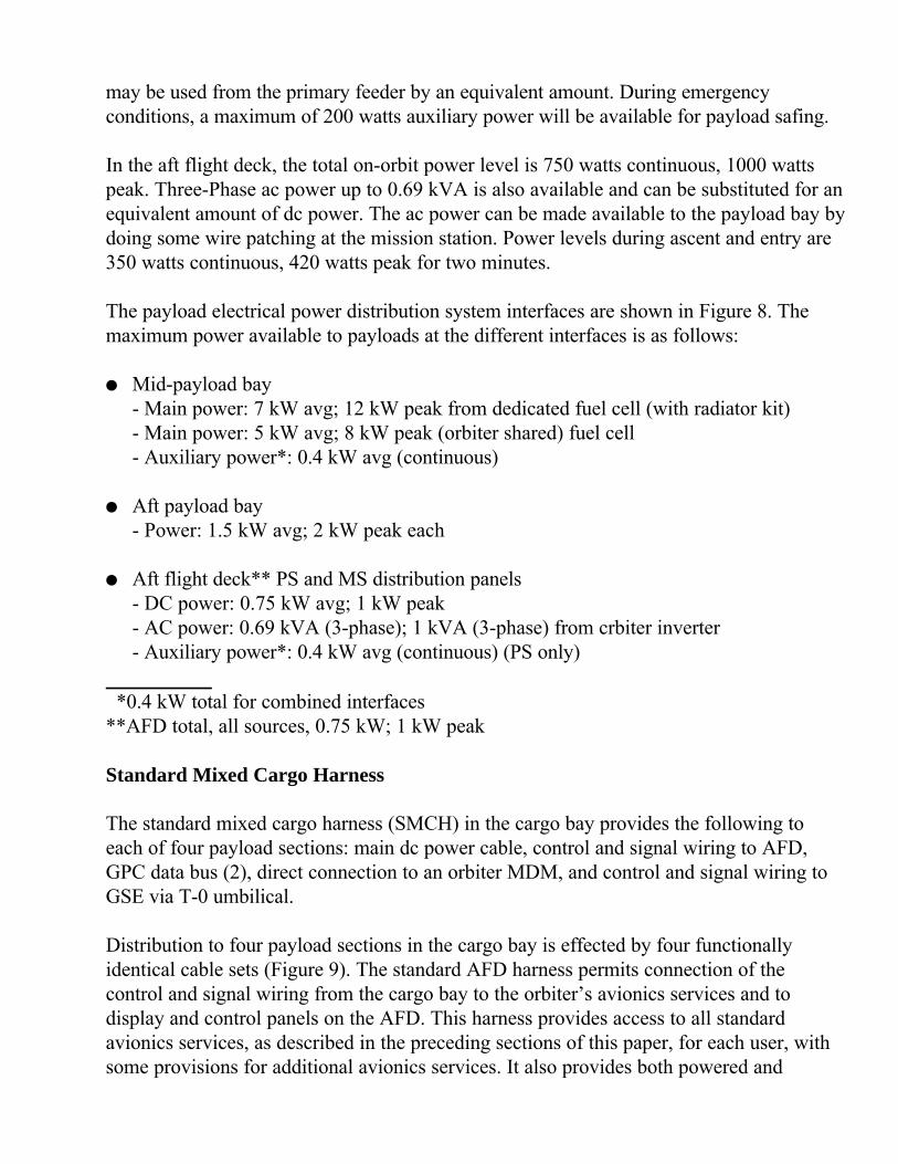
may be used from the primary feeder by an equivalent amount. During emergencyconditions, a maximum of 200 watts auxiliary power will be available for payload safing.
In the aft flight deck, the total on-orbit power level is 750 watts continuous, 1000 wattspeak. Three-Phase ac power up to 0.69 kVA is also available and can be substituted for anequivalent amount of dc power. The ac power can be made available to the payload bay bydoing some wire patching at the mission station. Power levels during ascent and entry are350 watts continuous, 420 watts peak for two minutes.
The payload electrical power distribution system interfaces are shown in Figure 8. Themaximum power available to payloads at the different interfaces is as follows:
� Mid-payload bay- Main power: 7 kW avg; 12 kW peak from dedicated fuel cell (with radiator kit)- Main power: 5 kW avg; 8 kW peak (orbiter shared) fuel cell- Auxiliary power*: 0.4 kW avg (continuous)
� Aft payload bay- Power: 1.5 kW avg; 2 kW peak each
� Aft flight deck** PS and MS distribution panels- DC power: 0.75 kW avg; 1 kW peak- AC power: 0.69 kVA (3-phase); 1 kVA (3-phase) from crbiter inverter- Auxiliary power*: 0.4 kW avg (continuous) (PS only)
*0.4 kW total for combined interfaces**AFD total, all sources, 0.75 kW; 1 kW peak
Standard Mixed Cargo Harness
The standard mixed cargo harness (SMCH) in the cargo bay provides the following toeach of four payload sections: main dc power cable, control and signal wiring to AFD,GPC data bus (2), direct connection to an orbiter MDM, and control and signal wiring toGSE via T-0 umbilical.
Distribution to four payload sections in the cargo bay is effected by four functionallyidentical cable sets (Figure 9). The standard AFD harness permits connection of thecontrol and signal wiring from the cargo bay to the orbiter’s avionics services and todisplay and control panels on the AFD. This harness provides access to all standardavionics services, as described in the preceding sections of this paper, for each user, withsome provisions for additional avionics services. It also provides both powered and

unpowered switch functions and electromechanical status indicators from the standardswitch panel. Figure 10 depicts the four SMCH sets that provide access to the signal andcontrol avionics services. Figures 11 and 12 depict the nonstandard avionics services at thepayload and mission stations that can be wire-patched to the payload interface using user-provided patch cables.
SUMMARY
The Shuttle avionics system provides a wide range of services to accommodate userpayloads, including commands, data management, displays and controls, data recording,RF communications, electrical power, aft flight deck displays and controls panel space,and standard wire harnesses. The standard avionics and electrical provisions have enoughflexibility to accommodate four major payloads per flight. The orbiter communicationsubsystem supports the transfer of payload telemetry and uplink data commands to andfrom the space networks. A payload recorder is provided for recording analog and digitaldata, which can be transmitted to ground stations via the orbiter communications system.A caution and warning subsystem is provided to monitor payload signals announcing afailure that could result in a hazard to the orbiter or crew. A standard switch panel isprovided for generating hardwired commands to attached payloads. The payload stationsin the orbiter cabin provide panel space for installing displays and controls unique to aspecific payload. Standardized electrical interfaces are provided for payload power,monitoring, command, and control. Standard wire harnesses are provided for use in thepayload specialist station and in the payload bay for connecting the standard avionics andelectrical services to four payloads. Payloads can avail themselves of the nonstandardavionics services by use of nonstandard harnesses, which require user funding.
The design of the orbiter-to-payload avionics interfaces and accommodations has beenoptimized to provide an efficient and flexible system that will accommodate mixed cargoflight requirements and will require minimum changes between flights. This highlyversatile avionics/electrical system for payload support, together with the flexibility of theShuttle system, will offer foreign as well as national space programs an effective, viablesystem for future space activities.
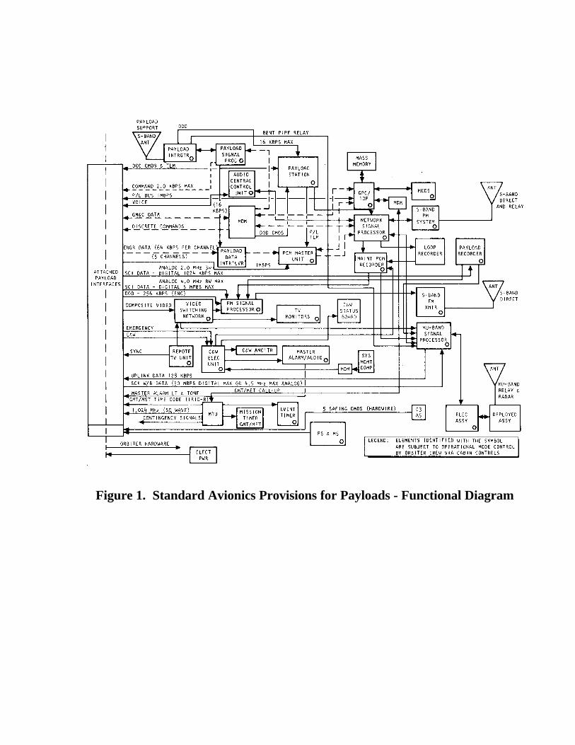
Figure 1. Standard Avionics Provisions for Payloads - Functional Diagram

Figure 2. Payload Command System Interface Block Diagram
Figure 3. Standard Switch Panel Front Panel Layout
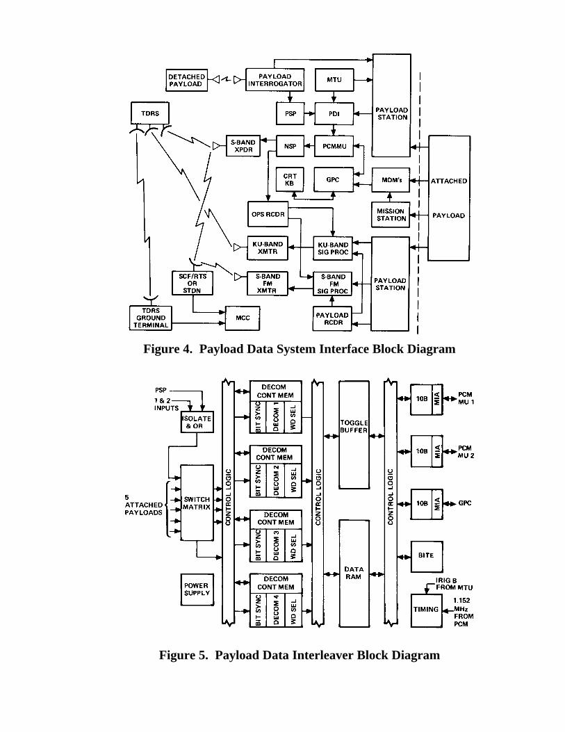
Figure 4. Payload Data System Interface Block Diagram
Figure 5. Payload Data Interleaver Block Diagram
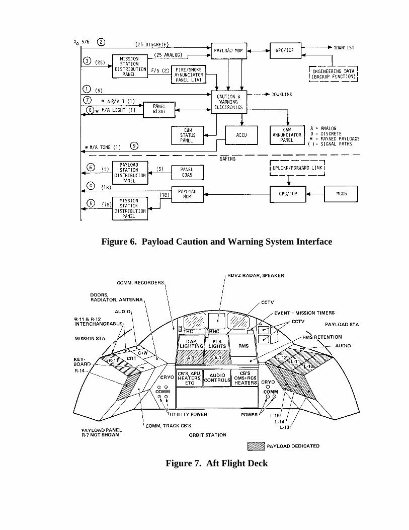
Figure 6. Payload Caution and Warning System Interface
Figure 7. Aft Flight Deck
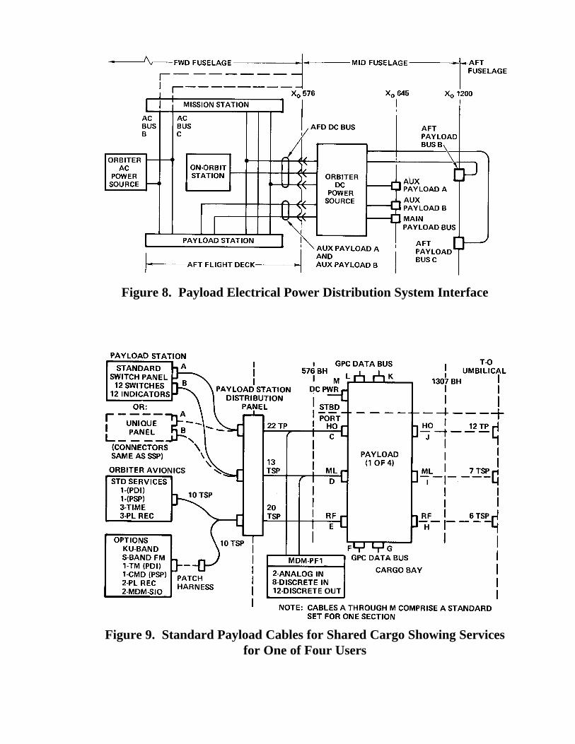
Figure 8. Payload Electrical Power Distribution System Interface
Figure 9. Standard Payload Cables for Shared Cargo Showing Servicesfor One of Four Users
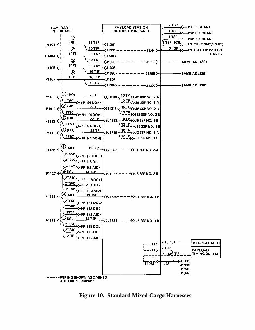
Figure 10. Standard Mixed Cargo Harnesses
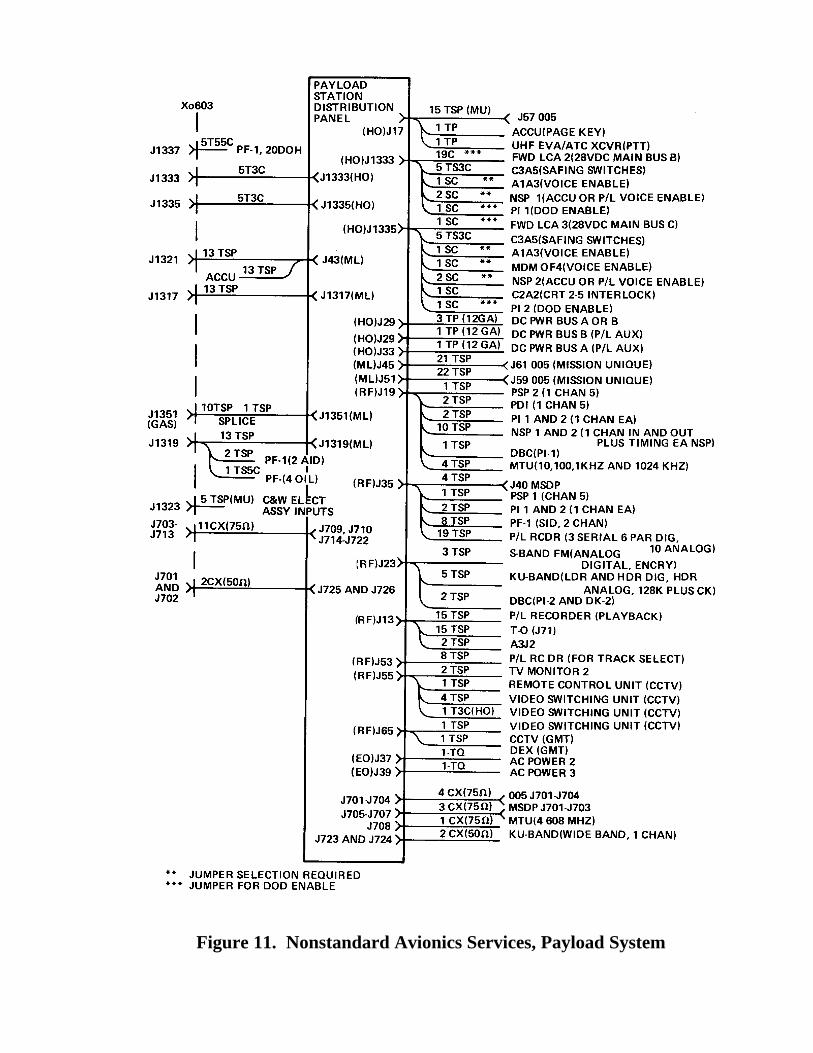
Figure 11. Nonstandard Avionics Services, Payload System
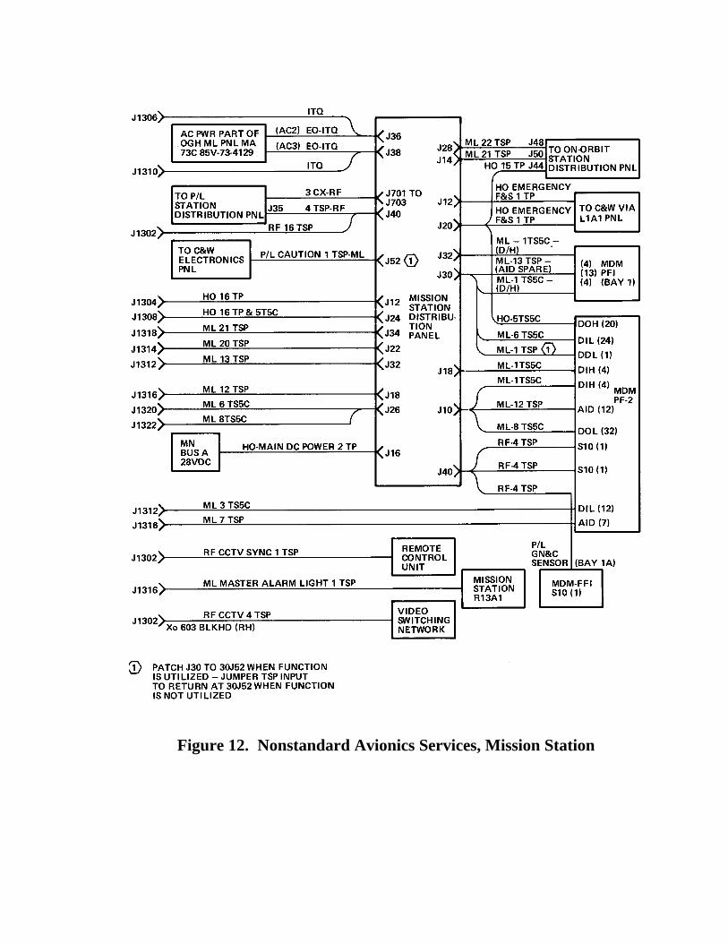
Figure 12. Nonstandard Avionics Services, Mission Station