Embed Size (px)
Citation preview
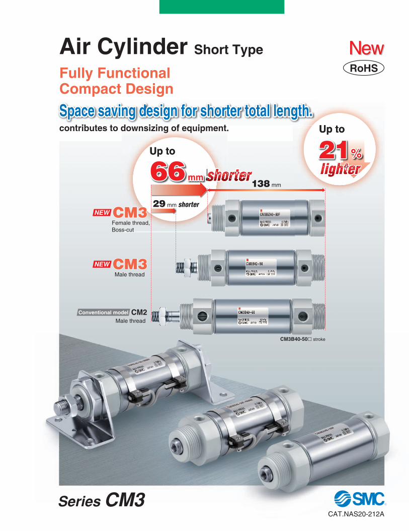
contributes to downsizing of equipment.
138 mm
CM3B40-50l stroke
Up toUp to
Up toUp to
shortershorter
Space saving design for shorter total length.Space saving design for shorter total length.Space saving design for shorter total length.
Air Cylinder Short Type
Fully FunctionalCompact Design
21%21%21%
66 mm66 mm66 mmlighterlighter
RoHS
CM3CM3CM3
CM2
Female thread,Boss-cut
Male thread
Male thread
NEW
CM3CM3CM3NEW
Conventional model
29 mm shorter
NewNew
Series CM3CAT.NAS20-212A

Series Variations
Series Bore size(mm) Action
Doubleacting
Rod
Single rod D-M9l(W), D-A90
Built-inmagnet forauto switch
Rubberbumper Auto switch
20, 25, 32, 40 25 to 300
Basic, Foot,
Flange, Clevis,
Trunnion
CM3
86°
90°
26°
Single clevis
Max. rotating angle 202°
Pivoting bracketRod trunnion
MountingStandard stroke(mm)
Series CM3
Selectable
Applications expanded by making it possible to select either male or female thread within the standard model.
Female rod end available as standard 2-color indication solid stateauto switch mountablePossible to confirm whether the position is appropriate at a glance. Shortens adjustment time.
A green light lights up at the optimum operating range.
Operating range OFF
ON
Red Green Red
Optimum operating range
Male thread Female thread
Shorter total length than CM2 series
Pivoting single clevis andtrunnion bracket are mountable.Rotation: Max. 202˚ (CM3C40)
Small auto switches are mountable.
Bore size (mm) Shortened by
20253240
17 mm
17 mm
13 mm
29 mm∗ Compared with the basic type with male thread
Total length
Tube is resistant to external impact.Prevents deformation and damage from external impact.
Features 1

M9BWWith auto switch CDM3
CM3 L
L 150
MountingBLFGCDU
TE
BZFZUZ
BasicFoot
Rod flangeHead flangeSingle clevis Double clevis Rod trunnion
Head trunnion Integral clevis Boss-cut/Basic
Boss-cut/Rod flange Boss-cut/Rod trunnion
Cylinder stroke (mm) Refer to the next page for standard strokes.
Nil Sn
2 pcs. 1 pc.
“n” pcs.
Number of auto switchesNilFG
Male threadFemale thread
Long male rod end∗
Rod end thread
Auto switch
Bore size20253240
20 mm25 mm32 mm40 mm
With auto switch (Built-in magnet)
40
40
150
Without auto switch
Nil
∗ For applicable auto switches, refer to the below table.
Applicable Auto Switches/Refer to pages 1263 to 1371 in Best Pneumatics No. 2 for further information on auto switches.
Built-in Magnet Cylinder ModelIf a built-in magnet cylinder without an auto switch is required, there is no need to enter the symbol for the auto switch.(Example) CDM3F32-100
5 V
12 V
—
5 V, 12 V
12 V
5 V, 12 V12 V
5 V, 12 V
12 V
5 V, 12 V
—
100 V100 V or less 100 V, 200 V 200 V or less
—24 V or less
—
100 V, 200 V
—
DC
24 V
24 V
AC
A96
A93 A90 B54 B64
C73C C80C A33A A34A A44A B59W
M9NM9PM9BH7C
G39AK39A M9NWM9PWM9BWH7BA H7NF
—
—
RoHS
∗ G: Same rod end dimensions(A, AL, H) as CM2 series.
How to Order
Type
Special function
Wiring (Output)
Load voltage
Ind
ica
tor
ligh
t Auto switch model
Pre-wired connector Applicable load
Lead wire length (m)
0.5(Nil)
1(M)
3(L)
5(Z)
None (N)
Diagnostic indication (2-color indication)
Diagnostic indication (2-color indication)
Water resistant (2-color indication)With diagnostic output (2-color indication)
Ree
dau
tosw
itch
So
lidst
ate
auto
swit
ch
Electrical entry
Grommet
Grommet
Grommet
Connector
Connector
Grommet
DIN terminal
Terminal conduit
Terminal conduit
Yes
Yes
NoNo
NoYe
sYe
sYe
s
3-wire (NPN) 3-wire (PNP)
2-wire
3-wire (NPN) 2-wire
2-wire
3-wire (NPN) 3-wire (PNP)
4-wire (NPN)
3-wire(NPN equivalent)
2-wire
IC circuit
—IC circuit
—
IC circuit
—
IC circuit
—
IC circuit —
IC circuit
—
IC circuit
—
PLC
Relay, PLC
Relay, PLC
Relay, PLC
∗ Solid state auto switches marked with “ ” are produced upon receipt of order. ∗ Do not indicate suffix “N” for no lead wire on the D-A3lA/A44A/G39A/K39A types. ∗ The D-G39A/K39A cannot be mounted on the bore size ø20. ∗ The D-A9lV/M9lV/M9lWV types and the D-M9lA(V)L type cannot be mounted.
∗ Lead wire length symbols: 0.5 m ·······Nil (Example) M9NW1 m ······· M (Example) M9NWM3 m ······· L (Example) M9NWL5 m ······· Z (Example) M9NWZ
None ······· N (Example) H7CN
∗ Since there are other applicable auto switches than listed above, refer to Best Pneumatics. ∗ For details about auto switches with pre-wired connector, refer to pages 1328 and 1329 in Best Pneumatics No. 2.∗ The D-A9l/M9l/M9lW type auto switches are shipped together, (but not assembled). (However, auto switch mounting brackets are assembled when
being shipped.)∗ Water resistant type auto switch can be mounted to the models with the above mentioned part numbers, but this does not guarantee the water resistance
of the cylinder. A water resistant type cylinder is recommended for use in an environment which requires water resistance.∗ For other applicable auto switches, please contact SMC.
ALA
H
1
Air Cylinder Short Type Standard: Double Acting, Single Rod
Series CM3ø20, ø25, ø32, ø40
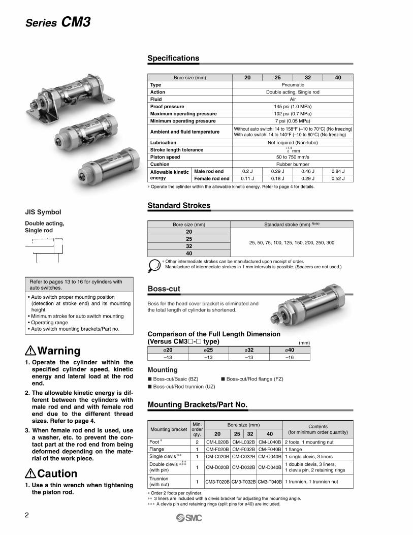
MountingL Boss-cut/Basic (BZ) L Boss-cut/Rod flange (FZ)
L Boss-cut/Rod trunnion (UZ)
Boss for the head cover bracket is eliminated and the total length of cylinder is shortened.
(mm)
ø20–13
ø25–13
ø32–13
ø40–16
Bore size (mm)
Foot
Flange
Single clevis
Double clevis(with pin)
Trunnion(with nut)
Mounting bracketContents
(for minimum order quantity)20 25 32 402
1
1
1
1
CM-L020B
CM-F020B
CM-C020B
CM-D020B
CM3-T020B
CM-L032B
CM-F032B
CM-C032B
CM-D032B
CM3-T032B
CM-L040B
CM-F040B
CM-C040B
CM-D040B
CM3-T040B
2 foots, 1 mounting nut
1 flange
1 single clevis, 3 liners
Min.order qty.
∗ Order 2 foots per cylinder.∗∗ 3 liners are included with a clevis bracket for adjusting the mounting angle.∗∗∗ A clevis pin and retaining rings (split pins for ø40) are included.
Boss-cut
Mounting Brackets/Part No.
Specifications
Standard Strokes
Type
Action
Fluid
Proof pressure
Maximum operating pressure
Minimum operating pressure
Ambient and fluid temperature
Lubrication
Stroke length tolerance
Piston speed
Cushion
Allowable kinetic energy
Pneumatic
Double acting, Single rod
Air
145 psi (1.0 MPa)
102 psi (0.7 MPa)
7 psi (0.05 MPa)
Not required (Non-lube)
50 to 750 mm/s
Rubber bumper
20 25 32 40
0.2 J
0.11 J
0.29 J
0.18 J
0.46 J
0.29 J
0.84 J
0.52 J
Without auto switch: 14 to 158°F (–10 to 70°C) (No freezing) With auto switch: 14 to 140°F (–10 to 60°C) (No freezing)
+1.4 0 mm
Male rod end
Female rod end
Bore size (mm)
Bore size (mm)
20253240
Standard stroke (mm) Note)
25, 50, 75, 100, 125, 150, 200, 250, 300
∗ Other intermediate strokes can be manufactured upon receipt of order. Manufacture of intermediate strokes in 1 mm intervals is possible. (Spacers are not used.)
∗ Operate the cylinder within the allowable kinetic energy. Refer to page 4 for details.
• Auto switch proper mounting position (detection at stroke end) and its mounting height
• Minimum stroke for auto switch mounting• Operating range• Auto switch mounting brackets/Part no.
Refer to pages 13 to 16 for cylinders with auto switches.
1 double clevis, 3 liners, 1 clevis pin, 2 retaining rings 1 trunnion, 1 trunnion nut
Warning1. Operate the cylinder within the
specified cylinder speed, kinetic energy and lateral load at the rodend.
2. The allowable kinetic energy is dif-ferent between the cylinders withmale rod end and with female rodend due to the different thread sizes. Refer to page 4.
3. When female rod end is used, usea washer, etc. to prevent the con-tact part at the rod end from beingdeformed depending on the mate-rial of the work piece.
Caution1. Use a thin wrench when tightening
the piston rod.
JIS Symbol
Double acting, Single rod
Comparison of the Full Length Dimension (Versus CM3l-l type)
2
Series CM3
∗
∗∗
∗∗∗∗∗
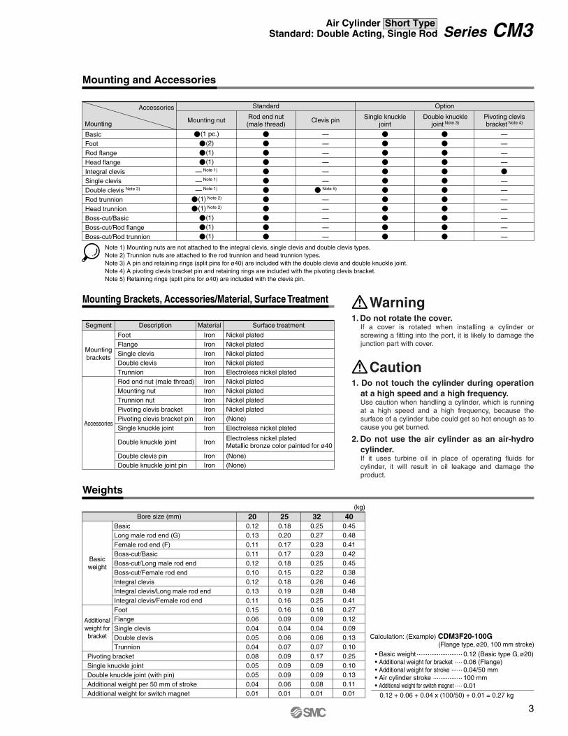
Accessories
Mounting
BasicFootRod flangeHead flangeIntegral clevis Single clevis Double clevis Note 3)
Rod trunnion Head trunnion Boss-cut/BasicBoss-cut/Rod flange Boss-cut/Rod trunnion
P(1 pc.)
P(2)
P(1)
P(1)
— Note 1)
— Note 1)
— Note 1)
P(1) Note 2)
P(1) Note 2)
P(1)
P(1)
P(1)
Standard Option
Mounting nut
PPPPPPPPPPPP
Rod end nut (male thread)
——————
P Note 5)
—————
Clevis pin
PPPPPPPPPPPP
Single knuckle joint
PPPPPPPPPPPP
Double knuckle joint Note 3)
————
P———————
Pivoting clevis bracket Note 4)
Description Material Surface treatmentSegment
Mountingbrackets
Accessories
FootFlangeSingle clevisDouble clevis Trunnion Rod end nut (male thread) Mounting nut Trunnion nut Pivoting clevis bracketPivoting clevis bracket pinSingle knuckle joint
Double knuckle joint Double clevis pin Double knuckle joint pin
IronIronIronIronIronIronIronIronIronIronIron
Iron
IronIron
Nickel platedNickel platedNickel platedNickel platedElectroless nickel plated Nickel platedNickel platedNickel platedNickel plated(None)Electroless nickel plated
(None)(None)
Bore size (mm)(kg)
Basicweight
Additionalweight for bracket
BasicLong male rod end (G)Female rod end (F)Boss-cut/BasicBoss-cut/Long male rod endBoss-cut/Female rod endIntegral clevisIntegral clevis/Long male rod endIntegral clevis/Female rod endFootFlangeSingle clevisDouble clevisTrunnion
Pivoting bracketSingle knuckle jointDouble knuckle joint (with pin)Additional weight per 50 mm of stroke Additional weight for switch magnet
200.120.130.110.110.120.100.120.130.110.150.060.040.050.040.080.050.050.040.01
0.180.200.170.170.180.150.180.190.160.160.090.040.060.070.090.090.090.060.01
0.250.270.230.230.250.220.260.280.250.160.090.040.060.070.170.090.090.080.01
0.450.480.410.420.450.380.460.480.410.270.120.090.130.100.250.100.130.110.01
25 32 40
Note 1) Mounting nuts are not attached to the integral clevis, single clevis and double clevis types. Note 2) Trunnion nuts are attached to the rod trunnion and head trunnion types. Note 3) A pin and retaining rings (split pins for ø40) are included with the double clevis and double knuckle joint. Note 4) A pivoting clevis bracket pin and retaining rings are included with the pivoting clevis bracket. Note 5) Retaining rings (split pins for ø40) are included with the clevis pin.
Electroless nickel plated Metallic bronze color painted for ø40
Mounting and Accessories
Mounting Brackets, Accessories/Material, Surface Treatment
Weights
1. Do not rotate the cover. If a cover is rotated when installing a cylinder or screwing a fitting into the port, it is likely to damage the junction part with cover.
Warning
1. Do not touch the cylinder during operation at a high speed and a high frequency. Use caution when handling a cylinder, which is running at a high speed and a high frequency, because the surface of a cylinder tube could get so hot enough as to cause you get burned.
2. Do not use the air cylinder as an air-hydro cylinder. If it uses turbine oil in place of operating fluids for cylinder, it will result in oil leakage and damage the product.
Caution
Calculation: (Example) CDM3F20-100G (Flange type, ø20, 100 mm stroke)
• Basic weight·························0.12 (Basic type G, ø20) • Additional weight for bracket ····0.06 (Flange) • Additional weight for stroke······0.04/50 mm • Air cylinder stroke················100 mm • Additional weight for switch magnet····0.01
0.12 + 0.06 + 0.04 x (100/50) + 0.01 = 0.27 kg
3
Series CM3Air Cylinder Short TypeStandard: Double Acting, Single Rod

NoteNo.
Component PartsDescription
Rod cover Head cover A Head cover B Head cover C Cylinder tubePistonPiston rod BushingBumper ABumper BRod sealPiston sealWear ring Mounting nut Rod end nut Bushing for clevis
12A2B2C34567891011121314
MaterialAluminum alloyAluminum alloyAluminum alloyAluminum alloyStainless steelAluminum alloy
IronCopper alloy
UrethaneUrethane
NBRNBRResinIronIron
Copper alloy
Anodized Anodized Anodized Anodized
Chromated
Hard chrome plated
Nickel plated Nickel plated
Male rod end
Female rod end
0.2
0.11
Bore size (mm) 200.29
0.18
250.46
0.29
320.84
0.52
40
20 25 32 40
20 25 32 40
[J]
Table (2) Mass of Cylinder Movable Parts:At Each Rod End/Without Built-in Magnet/0 Stroke
Basic
Long male rod end (G)
Female rod end (F)
31.2
39.4
22.4
Bore size (mm)
55.8
69.4
38.5
82.5
102.0
66.5
147.3
172.7
102.3
[g]
Table (3) Additional Mass
Additional mass per 50 mm of stroke
Switch magnet
19.6
3.5
Bore size (mm)
30.6
4.0
44.1
5.0
60.6
6.0
[g]
Kinetic energy E (J) =(m1 + m2) V2
2
∗ Mass of the rod end nut is included for the basic type and the long male rod end type (G).
∗ Do not apply a lateral load over the allowable range to the rod end when it is mounted horizontally.
Calculation: (Example) CDM3B40-175• Basic mass of movable parts: Table (2) Rod end [Basic], Bore size [40]··················· 147.3 g • Additional mass: Additional mass of stroke 60.6 x 175/50 = 212.1 g ···· 212.1 g Switch magnet ································································ 6.0 g
Total 365.4 g
m1: Mass of cylinder movable parts kgm2: Load mass kgV : Piston speed at the end m/s
With rubber bumper
Table (1) Max. Allowable Kinetic Energy
Allowable Kinetic Energy
Cylinder stroke (mm)
Allo
wab
lela
tera
lloa
dat
rod
end
(N)
10
50
10
150 100 150 200 250 300
Allowable Lateral Load at Rod End
Theoretical Output
Unit: N
Bore size D (mm)
Rod size d (mm)
Piston area (mm2)
Operating direction
Operating pressure (MPa)
20
25
32
40
8
10
12
14
OUT
IN
OUT
IN
OUT
IN
OUT
IN
314
264
491
412
804
691
1257
1103
0.2 0.3
125.6
105.6
196.4
164.8
321.6
276.4
502.8
441.2
157
132
245.5
206
402
345.5
628.5
551.5
188.4
158.4
294.6
247.2
482.4
414.6
754.2
661.8
219.8
184.8
343.7
288.4
562.8
483.7
879.9
772.1
0.70.60.50.4
94.2
79.2
147.3
123.6
241.2
207.3
377.1
330.9
62.8
52.8
98.2
82.4
160.8
138.2
251.4
220.6
∗ Theoretical outpt (N) = Pressure (MPa) x Piston area (mm2)
OUT IN
ø20
ø25
ø32
ø40
1. Not able to disassemble. Cover and cylinder tube are connected to each other by crimping method, thus making it impossible to disassemble.
Caution
Boss-cut Clevis integrated
t o y q u r !0 !4!1!3 !2 ie @A @C@B
4
Series CM3
Construction
Corner of the cover
2 x P 2 x NN
Width across flats B2
Width across flats B1
MM
Width across flats KA NA
øI
NA
R0.5
S + Stroke
ZZ + Stroke
H
ALF
øD
1.5 1.5
F
2x
øE
h8
GGH2
H1
A
ZZ + Stroke
Female thread MMDepth A1
HZZ + Stroke
2 x øLC
2 x P
2 x NN(Effective thread length 2 x FL)Width across flats B1
4 x øLDWidth across flats KA
Width across flats B2
Width acrossflats lNA
MM
LZ
LX
B
LH
S + Stroke
F
GGH2
H1
YXXYLS + Stroke
øD
F
øI
ALA
H
LT
ZZZ + Stroke
ALA
ZZ + Stroke
H
Bore size
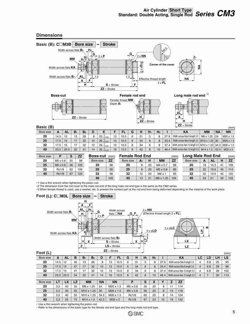
StrokeFoot (L): ClM3L
Boss-cut
Foot (L)Bore size
(mm)
20253240
A AL B40
47
47
54
B1
13
17
17
22
B2
26
32
32
41
D8
10
12
14
F13
13
13
16
FL10.5
10.5
10.5
13.5
G H H1
5
6
6
8
H2
8
8
8
10
I KA LC4
4
4
4
LD6.8
6.8
6.8
7
LH25
28
28
30
LS95
96
102
113
Bore size
20253240
LX40
40
40
55
LZ MM NA24
30
34.5
42.5
NNM20 x 1.5
M26 x 1.5
M26 x 1.5
M32 x 2
PM5 x 0.8
M5 x 0.8
Rc1/8
Rc1/8
S55
56
62
67
X20
20
20
23
Y8
8
8
10
Z ZZ114
118
124
142
Basic (B)Bore size
(mm)
0–0.033 0–0.033 0–0.033 0–0.039
20253240
A14.5
17.5
17.5
23.5
AL12
15
15
20.5
B1
13
17
17
22
B2
26
32
32
41
D8
10
12
14
F13
13
13
16
FL10.5
10.5
10.5
13.5
G6
6
8
8
H H1
5
6
6
8
H2
8
8
8
10
I KAE20
26
26
32
MMM8 x 1.25
M10 x 1.25
M10 x 1.25
M14 x 1.5
Bore size
20253240
NNM20 x 1.5
M26 x 1.5
M26 x 1.5
M32 x 2
P S ZZ Boss-cutBore size
20253240
ZZ
27.9
33.4
37.4
46.4
31
34
34
42
M5 x 0.8
M5 x 0.8
Rc1/8
Rc1/8
55
56
62
67
99
103
109
125
86
90
96
109
Female Rod EndH MM
M4 x 0.7
M5 x 0.8
M6 x 1
M8 x 1.25
20
20
20
21
ZZ88
89
95
104
Bore size
(mm)(mm)
20253240
A1
8
8
12
13
14.5
17.5
17.5
23.5
12
15
15
20.5
6
6
8
8
31
34
34
42
27.9
33.4
37.4
46.4
Width across flats 6 length 3.5
Width across flats 8 length 3.5
Width across flats 10 length 3.5
Width across flats 12 length 3.5
LT3.2
3.2
3.2
3.2
M8 x 1.25
M10 x 1.25
M10 x 1.25
M14 x 1.5
55
55
55
75
11
14
14
19
NA24
30
34.5
42.5
Long Male Rod EndAL H
41
45
45
50
15.5
19.5
19.5
21
ZZ109
114
120
133
Bore size
(mm)
20253240
A18
22
22
24
∗1 Use a thin wrench when tightening the piston rod. ∗2 The dimension from the rod cover to the male rod end of the long male rod end type is the same as the CM2 series. ∗3 When female thread is used, use a washer, etc. to prevent the contact part at the rod end from being deformed depending on the material of the work piece.
∗ Use a thin wrench when tightening the piston rod.∗ Refer to the dimensions of the basic type for the female rod end type and the long male rod end type.
Female rod end Long male rod end ∗2
2 x FLEffective thread length
Bore size
StrokeBasic (B): ClM3B
Width across flats 6 length 3.5
Width across flats 8 length 3.5
Width across flats 10 length 3.5
Width across flats 12 length 3.5
5
Series CM3Air Cylinder Short TypeStandard: Double Acting, Single Rod
Dimensions
Width across flats lNA
Corner ofthe cover
4 x øFDMounting hole
ø40
ø20 to ø32
2 x øFDMounting hole 2 x P 2 x NN
Width acrossflats B2
Width acrossflats B1
MM
Width acrossflats KA
R0.5
FZ
FX
FY B
C2
S + Stroke
øD
1.5
F
Effective thread length2 x FL
øE
h8
GGH2
H1
FT
øI
ALA
ZH
ZZ + Stroke
ø40ø20 to ø32 ZZ + Stroke
4 x øFD Mountinghole
ø40
Corner ofthe cover
2 x P2 x NN
Width across flats B1
MM
Widthacrossflats KA
Width across flats B2
FZ
FX
FY B
C2
S + Stroke
F1.5
Effective thread length 2 x FL
GG
H1
H2
FT
øI
øD
ALA
HZ + Stroke
ZZ + Stroke
Width across flats lNA
ø20 to ø32
2 x øFDMountinghole
øE
h8
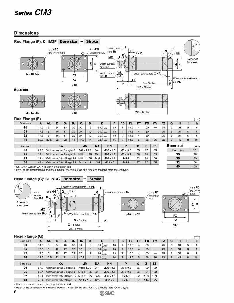
Rod Flange (F)Bore size
(mm)
20253240
A14.5
17.5
17.5
23.5
AL12
15
15
20.5
B34
40
40
52
B1
13
17
17
22
B2
26
32
32
41
C2
30
37
37
47.3
D8
10
12
14
F13
13
13
16
FL10.5
10.5
10.5
13.5
FD7
7
7
7
FT4
4
4
5
FX60
60
60
66
FY—
—
—
36
FZ75
75
75
82
G6
6
8
8
H31
34
34
42
H1
5
6
6
8
H2
8
8
8
10
Bore size
20253240
I27.9
33.4
37.4
46.4
KAWidth across flats 6 length 3.5
Width across flats 8 length 3.5
Width across flats 10 length 3.5
Width across flats 12 length 3.5
MMM8 x 1.25
M10 x 1.25
M10 x 1.25
M14 x 1.5
NA24
30
34.5
42.5
NNM20 x 1.5
M26 x 1.5
M26 x 1.5
M32 x 2
PM5 x 0.8
M5 x 0.8
Rc1/8
Rc1/8
S55
56
62
67
Z27
30
30
37
ZZ99
103
109
125
Boss-cutBore size
(mm)
20253240
ZZ86
90
96
109
0–0.033 0–0.033 0–0.033 0–0.039
E20
26
26
32
Boss-cut
Head Flange (G)Bore size
(mm)
20253240
A12
15
15
20.5
AL14.5
17.5
17.5
23.5
B34
40
40
52
B1
13
17
17
22
B2
26
32
32
41
C2
30
37
37
47.3
D8
10
12
14
F13
13
13
16
FL10.5
10.5
10.5
13.5
FD7
7
7
7
FT4
4
4
5
FX60
60
60
66
FY—
—
—
36
FZ75
75
75
82
G6
6
8
8
H31
34
34
42
H1
5
6
6
8
H2
8
8
8
10
Bore size
20253240
I27.9
33.4
37.4
46.4
KAWidth across flats 6 length 3.5
Width across flats 8 length 3.5
Width across flats 10 length 3.5
Width across flats 12 length 3.5
MMM8 x 1.25
M10 x 1.25
M10 x 1.25
M14 x 1.5
NA24
30
34.5
42.5
NNM20 x 1.5
M26 x 1.5
M26 x 1.5
M32 x 2
PM5 x 0.8
M5 x 0.8
Rc1/8
Rc1/8
S55
56
62
67
Z90
94
100
114
ZZ99
103
109
125
0–0.033 0–0.033 0–0.033 0–0.039
E20
26
26
32
∗ Use a thin wrench when tightening the piston rod. ∗ Refer to the dimensions of the basic type for the female rod end type and the long male rod end type.
∗ Use a thin wrench when tightening the piston rod.∗ Refer to the dimensions of the basic type for the female rod end type and the long male rod end type.
Bore size
StrokeRod Flange (F): ClM3F
Bore size
StrokeHead Flange (G): ClM3G
R0.5
6
Series CM3
Dimensions

R0.5
Corner of the cover
2 x PNN
Width across flats KA
MM
Width across flats B1
NA
NA
øI
–0.1–0.2CX
S + Stroke
1.5
Effective threadlength FL
GG
L
U
RR
øC
I
øD
H1
AL
A
H
F
Z + Stroke
ZZ + Stroke
Corner of the cover
2 x PNN
Width across flats B1
Width across flats KA
MM
NA
NA
øI
CZ
+0.2 +0.1CX
CL
S + Stroke
F
1.5
Effective threadlength FL
GG
L
U
øC
I
RR
H
øD
H1
AL
A
Z + Stroke
ZZ + Stroke
R0.5
øE
h8øE
h8
Single Clevis (C)Bore size
(mm)
20253240
A14.5
17.5
17.5
23.5
AL12
15
15
20.5
B1
13
17
17
22
CI24
30
30
38
CD9
9
9
10
CX10
10
10
15
D8
10
12
14
F13
13
13
16
FL10.5
10.5
10.5
13.5
G6
6
8
8
H31
34
34
42
H1
5
6
6
8
I27.9
33.4
37.4
46.4
KAWidth across flats 6 length 3.5
Width across flats 8 length 3.5
Width across flats 10 length 3.5
Width across flats 12 length 3.5
L30
30
30
39
Bore size
20253240
NA24
30
34.5
42.5
NNM20 x 1.5
M26 x 1.5
M26 x 1.5
M32 x 2
PM5 x 0.8
M5 x 0.8
Rc1/8
Rc1/8
RR9
9
9
11
S55
56
62
67
U14
14
14
18
Z116
120
126
148
ZZ125
129
135
159
0–0.033 0–0.033 0–0.033 0–0.039
E20
26
26
32
Double Clevis (D)Bore size
(mm)
20253240
A14.5
17.5
17.5
23.5
AL12
15
15
20.5
B1
13
17
17
22
CD9
9
9
10
CI24
30
30
38
CL25
25
25
41.2
CX10
10
10
15
CZ19
19
19
30
D8
10
12
14
F13
13
13
16
FL10.5
10.5
10.5
13.5
G6
6
8
8
H31
34
34
42
H1
5
6
6
8
I27.9
33.4
37.4
46.4
KAWidth across flats 6 length 3.5
Width across flats 8 length 3.5
Width across flats 10 length 3.5
Width across flats 12 length 3.5
Bore size
20253240
MMM8 x 1.25
M10 x 1.25
M10 x 1.25
M14 x 1.5
NA24
30
34.5
42.5
NNM20 x 1.5
M26 x 1.5
M26 x 1.5
M32 x 2
PM5 x 0.8
M5 x 0.8
Rc1/8
Rc1/8
RR9
9
9
11
S55
56
62
67
U14
14
14
18
Z116
120
126
148
ZZ125
129
135
159
0–0.033 0–0.033 0–0.033 0–0.039
E20
26
26
32
MMM8 x 1.25
M10 x 1.25
M10 x 1.25
M14 x 1.5
L30
30
30
39
∗ Use a thin wrench when tightening the piston rod. ∗ Refer to the dimensions of the basic type for the female rod end type and the long male rod end type.
∗ A clevis pin and retaining rings (split pins for ø40) are shipped together.∗ Use a thin wrench when tightening the piston rod.∗ Refer to the dimensions of the basic type for the female rod end type and the long male rod end type.
Bore size
StrokeSingle Clevis (C): ClM3C
Bore size
StrokeDouble Clevis (D): ClM3D
øCDH10+0.058
0
øCD hole H10
Axis d9
+0.058 0
–0.040 –0.076
7
Series CM3Air Cylinder Short TypeStandard: Double Acting, Single Rod
Dimensions
Width across flatslNA
Width across flats lNA
Corner of the cover
2 x P2 x NN
Width across flats B2
Widthacrossflats B1
MM
Width across flats KA R0.5
TZTX –0
.025
–0.0
61øT
De9
øT
Y
S + Stroke
ZZ + StrokeøD
1.5
F
Effective thread length 2 x FL
øE
h8
GG
H1
TT
øI
ALA
ZH
ZZ + Stroke
Corner of the cover
2 x P2 x NN
Width across flats B1
MM
Widthacrossflats KA
Width across flats B2
TZTX
–0.0
25–0
.061
øT
De9
øT
YR0.5
S + Stroke
F1.5
Effective thread length 2 x FL
GG
H1
øI
TT
øD
ALA
HZ + StrokeZZ + Stroke
øE
h8
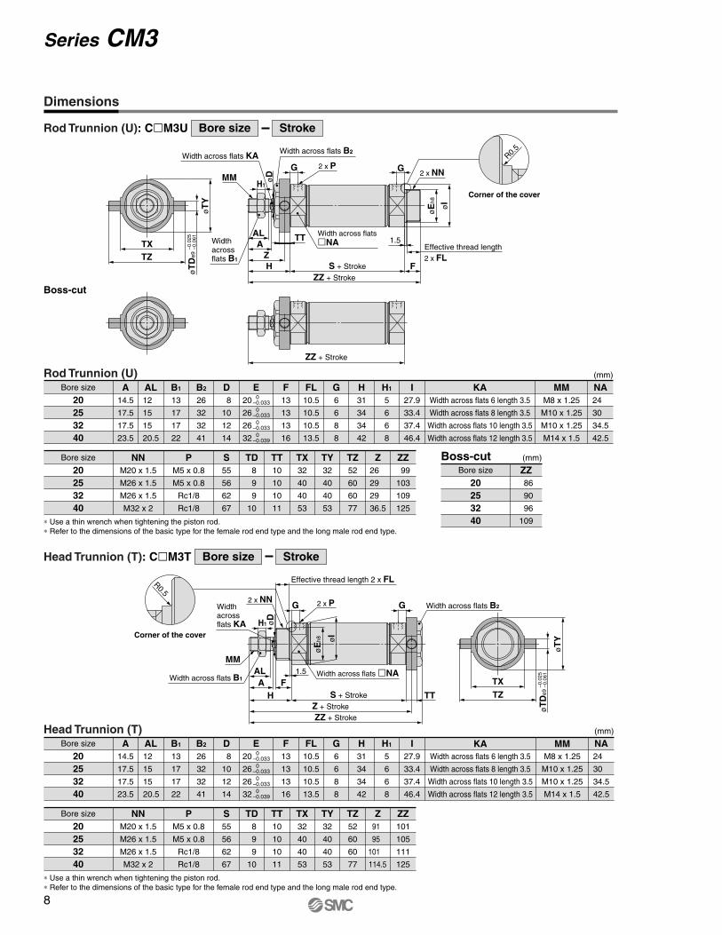
Rod Trunnion (U)Bore size
(mm)
20253240
A14.5
17.5
17.5
23.5
AL12
15
15
20.5
B1
13
17
17
22
B2
26
32
32
41
D8
10
12
14
F13
13
13
16
FL10.5
10.5
10.5
13.5
G6
6
8
8
H31
34
34
42
H1
5
6
6
8
I27.9
33.4
37.4
46.4
KAWidth across flats 6 length 3.5
Width across flats 8 length 3.5
Width across flats 10 length 3.5
Width across flats 12 length 3.5
MMM8 x 1.25
M10 x 1.25
M10 x 1.25
M14 x 1.5
24
30
34.5
42.5
NA0
–0.0330
–0.0330
–0.0330
–0.039
E20
26
26
32
Bore size 20
253240
NNM20 x 1.5
M26 x 1.5
M26 x 1.5
M32 x 2
PM5 x 0.8
M5 x 0.8
Rc1/8
Rc1/8
S55
56
62
67
TD8
9
9
10
TT10
10
10
11
TX32
40
40
53
TY32
40
40
53
TZ52
60
60
77
Z26
29
29
36.5
ZZ99
103
109
125
Boss-cutBore size
(mm)
20253240
ZZ86
90
96
109
Head Trunnion (T)Bore size
(mm)
20253240
A14.5
17.5
17.5
23.5
AL12
15
15
20.5
B1
13
17
17
22
B2
26
32
32
41
D8
10
12
14
F13
13
13
16
FL10.5
10.5
10.5
13.5
G6
6
8
8
H31
34
34
42
H1
5
6
6
8
I27.9
33.4
37.4
46.4
KAWidth across flats 6 length 3.5
Width across flats 8 length 3.5
Width across flats 10 length 3.5
Width across flats 12 length 3.5
MMM8 x 1.25
M10 x 1.25
M10 x 1.25
M14 x 1.5
NA24
30
34.5
42.5
Bore size 20
253240
NNM20 x 1.5
M26 x 1.5
M26 x 1.5
M32 x 2
P S55
56
62
67
TD8
9
9
10
TT10
10
10
11
TX32
40
40
53
TY32
40
40
53
TZ52
60
60
77
Z91
95
101
114.5
ZZ101
105
111
125
0–0.0330
–0.0330
–0.0330
–0.039
E20
26
26
32
Boss-cut
∗ Use a thin wrench when tightening the piston rod. ∗ Refer to the dimensions of the basic type for the female rod end type and the long male rod end type.
∗ Use a thin wrench when tightening the piston rod.∗ Refer to the dimensions of the basic type for the female rod end type and the long male rod end type.
Bore size
StrokeRod Trunnion (U): ClM3U
Bore size
StrokeHead Trunnion (T): ClM3T
M5 x 0.8
M5 x 0.8
Rc1/8
Rc1/8
Series CM3
8
Dimensions

Corner of the cover
2 x P
2 x øLDNN
Width across flats KA
Width across flats B1
MM
+0.058 0øCDH10
R0.5
NA
NA
øI
LV
0–0.1CX
LH
S + Stroke
F
øD
1.5
Effective threadlength FL
GG
H1
L RR
U
øC
I
LY
LF LGLT
LP
AL
A
H
Z + Stroke
ZZ + Stroke
LZ + Stroke
øE
h8
Integral Clevis (E)Bore size
(mm)
20253240
A14.5
17.5
17.5
23.5
AL12
15
15
20.5
B1
13
17
17
22
CD8
8
10
10
CI20
22
27
33
CX12
12
20
20
D8
10
12
14
F13
13
13
16
FL10.5
10.5
10.5
13.5
G6
6
8
8
H31
34
34
42
H1
5
6
6
8
I27.9
33.4
37.4
46.4
KAWidth across flats 6 length 3.5
Width across flats 8 length 3.5
Width across flats 10 length 3.5
Width across flats 12 length 3.5
0–0.033 0–0.033 0–0.033 0–0.039
E20
26
26
32
Bore size
20253240
NA24
30
34.5
42.5
NNM20 x 1.5
M26 x 1.5
M26 x 1.5
M32 x 2
PM5 x 0.8
M5 x 0.8
Rc1/8
Rc1/8
RR9
9
12
12
S55
56
62
67
U11.5
11.5
14.5
14.5
Z98
102
111
124
ZZ107
111
123
136
Pivoting Clevis BracketBore size
(mm)
20253240
LD6.8
6.8
9
9
LF15
15
15
15
LG30
30
40
40
LH30
30
40
40
LP37
37
50
50
LT3.2
3.2
4
4
LV18.4
18.4
28
28
LY59
59
75
75
LZ135
139
161
174
Refer to page 11 for details of pivoting clevis bracket.
MMM8 x 1.25
M10 x 1.25
M10 x 1.25
M14 x 1.5
L12
12
15
15
∗ Use a thin wrench when tightening the piston rod.∗ Refer to the dimensions of the basic type for the female rod end type and the long male rod end type.
Bore size
StrokeIntegral Clevis (E): ClM3E
9
Series CM3Air Cylinder Short TypeStandard: Double Acting, Single Rod
Dimensions

Single Knuckle Joint (mm)
I-020B, I-032B Material: Iron I-040B Material: Iron
Double Knuckle Joint (mm)
U1
14
14
20
Part no.
I-020BI-032BI-040B
Applicable bore size
2025, 32
40
A46
48
69
A1
16
18
22
E1
20
20
24
L1
36
38
55
MMM8 x 1.25
M10 x 1.25
M14 x 1.5
9
9
12
+0.058 0+0.058 0+0.070 0
NX–0.1 –0.2–0.1 –0.2–0.1 –0.3
9
9
16
NDH10 R1
10
10
15.5
Y-020B, Y-032B Material: Iron
Material: Iron Material: Iron
Y-040B Material: Cast iron
Part no.
Y-020BY-032BY-040B
A
46
48
68
A1
16
18
22
E1
20
20
24
L
25
25
49.7
L1
36
38
55
MM
M8 x 1.25
M10 x 1.25
M14 x 1.5
NX
+0.2 +0.1+0.2 +0.1+0.3 +0.1
9
9
16
NZ
18
18
38
R1
5
5
13
U1
14
14
25
Included pin part no.
CDP-1
CDP-1
CDP-3
size
Type C9 for axis
Type C9 for axis
ø3 x 18 l
ND
9
9
12
Applicable bore size
2025, 32
40
Retaining ring Split pin
∗ A knuckle pin and retaining rings (split pins for ø40) are included.
CDP-1 Material: IronCDP-1 Material: IronCDP-2 CDP-3
øø
ø
ø
ø
ø
ø
x
∗ Use a thin wrench when tightening the piston rod.
øND hole H10Axis d9
øND hole H10Axis d9
Double Clevis Pin (mm) Double Knuckle Joint Pin (mm)
Bore size/ø20, ø25, ø32 Bore size/ø40 Bore size/ø20, ø25, ø32 Bore size/ø40
Retaining ring: Type C9 for axis Split pin: ø3 x 18 l Split pin: ø3 x 18 lRetaining ring: Type C9 for axis
∗ Retaining rings (split pins for ø40) are included. ∗ Retaining rings (split pins for ø40) are included.
2 x ø3Drill through Drill through
MM
A1 U1L1
øE
1
øND
øE
1
MM
A1
NX
R1
øND
R1
U1
L1
AA
NX
MM MM
A1 U1
L1
A
øE
1
øE
1
A1 U1
L1
A
R1 R1
NX
NZ L NX
NZ L
10
Series CM3Dimensions of Accessories 1

øD C
H B
d
øD C
H B
d
øD
øC
H
B
d
CM-E020BCM-E032B
20, 25 32, 40
Applicable bore size
Part no.
Rod End Nut (mm)
Trunnion Nut (mm)
Mounting Nut (mm)
Material: Iron
Material: Iron
Material: Iron
Part no.
NT-02NT-03NT-04
Applicable bore size
2025, 32
40
B13
17
22
C15.0
19.6
25.4
D12.5
16.5
21.0
dM8 x 1.25
M10 x 1.25
M14 x 1.5
H5
6
8
Part no.
SN-020BSN-032BSN-040B
Applicable bore size
2025, 32
40
B26
32
41
C30
37
47.3
D25.5
31.5
40.5
dM20 x 1.5
M26 x 1.5
M32 x 2.0
H8
8
10
Part no.
TN-020BTN-032BTN-040B
Applicable bore size
2025, 32
40
B26
32
41
C28
34
45
D25.5
31.5
40.5
dM20 x 1.5
M26 x 1.5
M32 x 2
H10
10
10
øLD
LR
LG
LLVLX
LFLE
LY
LT L
H
Pivoting Clevis Bracket (For CM3E) (mm)
Pivoting Clevis Bracket Pin (For CM3E) (mm)
Material: Iron
Material: Iron
CM-E020BCM-E032B
20, 25 32, 40
Applicable bore size
Dd9
–0.040 –0.076
8
10
–0.040–0.076
LD
6.8
9
LC
8
10
L
24.5
34
LE
22
25
LF
15
15
LG
30
40
Included pin part no.
LH
30
40
LR
10
13
LT
3.2
4
LX
12
20
LY
59
75
LV
18.4
28
CD-S02
CD-S03
Part no.
CD-S02CD-S03
Applicable bore size
20, 25 32, 40
d
7.6
9.6
L
24.5
34
l
19.5
29
m
1.6
1.35
Note) Retaining rings are included.
t
0.9
1.15
Type C8 for axis
Type C10 for axis
lø
dø
D
m m
tt L
Part no.
Included retaining ring
Note 1) A pivoting clevis bracket pin and retaining rings are included. Note 2) It cannot be used for the single clevis (CM3C) and double clevis
(CM3D) types.
11
Series CM3Dimensions of Accessories
øLC hole +0.15 +0.05
Axis –0.040 –0.076

6.8 x 3.4
øTD
ø6.8
51 40 3.2
LXLZ
TX Z
7.5
20.5
40
57
tt
m m
ød
øD
d9
L
+0.15+0.05øCD
±0.2
17
25
ø6.8
7.5 40
R3.4
3.4
R3.4
6.8
57
28
3.2
5.2 40
R11
±0.2
17
25
ø6.8
7.540
R3.4
3.4
R3.4
6.8
+0.15+0.05øCD
5728
3.25.240
R11
l
A°
ø6.8
6.8 x 3.4
øCDB°
90°
Z + Stroke
7.520.5
4057
5140
3.2
LXLZ
CX
ø6.8
6.8 x 3.4
øTDZ + Stroke
20.57.5 40
57
TX
LXLZ
3.2 40 51
Pivoting Bracket Pivoting Bracket Pin
LSingle Clevis (C)
LRod Trunnion (U) LHead Trunnion (T)
Rotating Angle
Note 1) A pivoting bracket pin and retaining rings are not included with the pivoting bracket. Note 2) The above dimensions are for the male rod end type.
A°+ B°+ 90°A°Bore size (mm)
2025, 32
40
25
21
26
B°
85
81
86
200
192
202
CDPart no.
CM-B020CM-B032CM-B040
8
9
10
Mounting Part no.
Applicable bore size Z + StrokeCX CD
CM3C(Single clevis)
CM-B032
CM-B040
116
120
126
148
20253240
10
15
9
10
LX
44
49
LZ
60
65
(mm)
Note 1) A pivoting bracket pin and retaining rings are not included with the pivoting bracket. Note 2) The above dimensions are for the male rod end type.
Note) Retaining rings are included with the pivoting bracket pin.
∗ Pivoting brackets consist of a set of two brackets.
Mounting Part no.
Applicable bore size
Rod trunnion
ZTX TD
CM3U, CM3T(Rod trunnion, Head trunnion)
CM-B020
CM-B032
CM-B040
26
29
36.5
Head trunnion
Z + Stroke
91
95
101
114.5
20253240
32
40
53
8
9
10
LX
66
74
87
LZ
82
90
103
(mm)
(mm)(mm)
dPart no.Applicable bore size
Included retaining ring
20, 25, 32 40
CDP-1CD-S03
Type C9 for axis
Type C10 for axis
Dd9
9 –0.040 –0.076
10 –0.040 –0.076
8.6
9.6
L
25
34
l
19.2
29
m
1.75
1.35
t
1.15
1.15Note) A pivoting bracket pin and retaining rings arenot included with the pivoting bracket.
12
Series CM3Dimensions of Accessories 2
Dimensions

Auto Switch Proper Mounting Position (Detection at stroke end) and Its Mounting Height
B22A(24.5)
D-M9lD-M9lW
D-A9l16
.5
16.5
≈ Hs
B22A
Auto switch
D-B54/B64/B59W
D-A33A/A34A
D-A44A
D-C73C/C80C
D-H7NF/H7BAL
D-G5NTL
D-G39A/K39A
D-H7C
BA
BA
BA
BA
BA
BA
BA
BA
Reed auto switch
Solid state auto switch
≈ Hs
( ): Dimensions of D-A93 type
Auto switch
≈ Hs
Auto switch
Auto switch
≈ Hs G1/2 (Applicable cable O.D. ø6.8 to ø9.6)
Auto switch
G1/2 (Applicable cable O.D. ø6.8 to ø11.5)
≈ Hs
Auto switch≈ Hs
Auto switch
≈ Hs
Auto switch
≈ Hs
G1/2 (Applicable cable O.D. ø6.8 to ø9.6)
≈ Hs
Auto switch≈ Hs
Auto switch
13
Series CM3Air Cylinder Short TypeStandard: Double Acting, Single Rod

Auto Switch Proper Mounting Position (Detection at stroke end) and Its Mounting Height
Auto Switch Mounting HeightAuto switch
model
Bore size
20253240
Hs25.5
28
31.5
35.5
Hs22.5
25
28.5
32.5
Hs25
27.5
31
35
Hs60
62.5
66
70
Hs69.5
72
75.5
79.5
D-H7BALD-H7NF
D-A3lAD-G39A Note)
D-K39A Note)
D-C73CD-C80C D-A44A
Hs22
24.5
28
32
D-M9lD-M9lWD-A9l
D-B54D-B64D-B59WD-G5NTLD-H7C
(mm)
Note 1) Adjust the auto switch after confirming the operating condition in the actual setting. Note 2) The D-G39A/K39A cannot be mounted on the bore size ø20. Note 3) For the combination of the following auto switches, bore sizes and mounting positions, the auto switch cannot be mounted to the port side. • D-G5l type: On the head side and the rod side of the bore size ø32 • D-B5l/B64 types (except B59W) ··· On the head side of the bore size ø20, ø32, On the rod side of the bore size ø32
Note) The D-G39A/K39A cannot be mounted on the bore size ø20.
Auto Switch Proper Mounting PositionAuto switch
model
Bore size A6.5
6.5
6.5
8.5
B5.5
6.5
6.5
8.5
A3.5
3.5
3.5
5.5
B2.5
3.5
3.5
5.5
A0
0
0
2
B0
0
0
2
A5.5
5.5
5.5
7.5
B4.5
5.5
5.5
7.5
A2
2
2
4
B1
2
2
4
D-C73C D-C80C
A0.5
0.5
0.5
2.5
B0
0.5
0.5
2.5
D-B54D-B64
A10
10
10
12
B9
10
10
12
D-M9lD-M9lW D-A9l D-B59W
D-H7CD-H7BAL D-H7NF
D-G5NTL
A6
6
6
8
B5
6
6
8
D-A3lAD-A44A D-G39A Note 2)
D-K39A Note 2)
(mm)
20253240
14
Series CM3
D-H7BAL/H7NF
D-C73C/C80CD-H7C
D-B54/B64D-G5NTL
D-B59W
D-A3mA/A44AD-G39AD-K39A
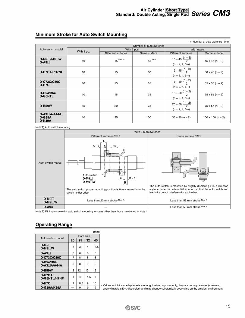
10 15 60
10 15 65
35 + 30 (n – 2)
60 + 45 (n – 2)
65 + 50 (n – 2)
75 + 55 (n – 2)
75 + 55 (n – 2)
100 + 100 (n – 2)
10 15 75
15 20 75
10 35 100
D-M9m/M9mWD-A9m
Auto switch modelWith 1 pc.
With 2 pcs.Different surfaces
With n pcs.Number of auto switches
10 15Note 1) Note 1)
Same surface
45
Same surface
45 + 45 (n – 2)
n: Number of auto switches (mm)
Different surfaces
15 + 45
(n = 2, 4, 6···)
(n – 2)2
15 + 45
(n = 2, 4, 6···)
(n – 2)2
15 + 50
(n = 2, 4, 6···)
(n – 2)2
15 + 50
(n = 2, 4, 6···)
(n – 2)2
20 + 50
(n = 2, 4, 6···)
(n – 2)2
Note 2) Minimum stroke for auto switch mounting in styles other than those mentioned in Note 1
Note 1) Auto switch mounting
Operating Range
Auto switch modelBore size
20 25 32
3
6
7
8
12
4
7
—
3
6
8
8
12
4
8.5
9
4
6
8
9
13
4.5
9
9
40
3.5
6
8
9
13
5
10
9
D-B54/B64D-A3mA/A44A
D-H7BALD-G5NTL/H7NF
D-A9mD-C73C/C80C
D-B59W
D-H7CD-G39A/K39A
D-M9mD-M9mW
(mm)
∗ Values which include hysteresis are for guideline purposes only, they are not a guarantee (assuming approximately ±30% dispersion) and may change substantially depending on the ambient environment.
D-A93
D-M9mD-M9mW
Auto switch model
With 2 auto switches
Different surfaces Note 1)
—
Less than 20 mm stroke Note 2)
Same surface Note 1)
Less than 50 mm stroke Note 2)
Less than 55 mm stroke Note 2)
The auto switch is mounted by slightly displacing it in a direction(cylinder tube circumferential exterior) so that the auto switch and lead wire do not interfere with each other.
The auto switch proper mounting position is 6 mm inward from the switch holder edge.
B – 6
A – 6 15
6
B
6
A
Auto switchD-M9mD-M9mW
Minimum Stroke for Auto Switch Mounting
15
Series CM3Air Cylinder Short TypeStandard: Double Acting, Single Rod

Note 1) Two kinds of auto switch mounting brackets are used as a set.Note 2) The D-G39A/K39A cannot be mounted on the bore size ø20.
[Stainless Steel Mounting Screw]The following stainless steel mounting screw is available. Use it in accordance with the operating environment. (Since auto switch mounting bracket is not included, order it separately.) BBA4: For D-C7/C8/H7 typesNote 3) Refer to page 1358 in Best Pneumatics No. 2 for details of BBA4 screws. The above stainless steel screws are used when a cylinder is shipped with the D-H7BAL auto switches. When only an auto switch is shipped independently, the BBA4 screw is attached.
Auto switch modelBore size (mm)
D-C73C/C80CD-H7BALD-H7NF
D-M9L D-M9LWD-A9L
D-B54/B64D-B59WD-G5NTLD-G5NBL
D-A3LA/A44AD-G39A/K39A
ø20
BM2-020
BA2-020
BM3-020 Note 2)
ø25
BM2-025
BA2-025
BM3-025
ø32
BM2-032
BA2-032
BM3-032
ø40
BM2-040
BA2-040
BM3-040
Note 1)
BM2-020BJ3-1
Note 1)
BM2-025BJ3-1
Note 1)
BM2-032BJ3-1
Note 1)
BM2-040BJ3-1
∗ With pre-wired connector is also available for solid state auto switches. For details, refer to pages 1328 and 1329 in Best Pneumatics No. 2.∗ Normally closed (NC = b contact) solid state auto switches (D-F9G/F9H) are also available. For details, refer to page 1290 in Best Pneumatics No. 2.∗ Solid state auto switch with timer (D-G5NTL) is also available. For details, refer to page 1313 in Best Pneumatics No. 2.∗ Wide range detection type, solid state auto switch (D-G5NBL) is also available. For details, refer to page 1320 in Best Pneumatics No. 2.
Other than the applicable auto switches listed in “How to Order,” the following auto switches are mountable.Refer to pages 1263 to 1371 in Best Pneumatics No. 2 for detailed specifications.
e
d
cb
a
Switch holder(Resin)
Switch bracket(Stainless steel)
Auto switch mounting screw
Switch spacer(Stainless steel)
1. BM2-LLL: A set of a and b above 2. BJ3-1: A set of c, d and e above
Auto switch mounting band
Auto Switch Mounting Brackets/Part No.
Auto switch
Set screw (Not used)
16
Series CM3
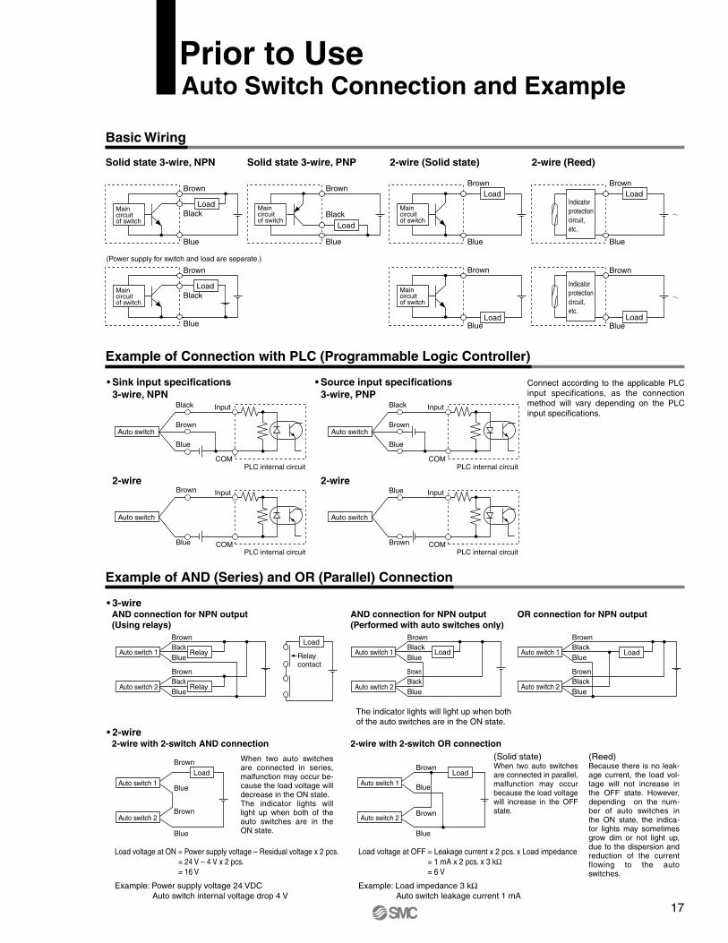
Basic Wiring
Solid state 3-wire, NPN 2-wire (Solid state)Solid state 3-wire, PNP
(Power supply for switch and load are separate.)
Maincircuitof switch
Brown
Black
Blue
Load
Brown
Black
Blue
Maincircuitof switch
Load
Maincircuitof switch
Brown
Black
Blue
Load
Maincircuitof switch
Brown
Blue
Load
Brown
Blue
Maincircuitof switch
Load
2-wire (Reed)
Indicator protection circuit, etc.
Brown
Blue
Load
Indicator protectioncircuit, etc.
Brown
BlueLoad
• Sink input specifications 3-wire, NPN
• Source input specifications 3-wire, PNP
2-wire 2-wire
Connect according to the applicable PLC input specifications, as the connection method will vary depending on the PLC input specifications.
Auto switch
InputBlack
COM
Brown
Blue
Auto switch
Input
Blue COM
Brown
Auto switch
InputBlack
PLC internal circuitCOM
Brown
Blue
PLC internal circuit
PLC internal circuit
PLC internal circuit
Auto switch
InputBlue
COMBrown
Example of Connection with PLC (Programmable Logic Controller)
• 3-wireOR connection for NPN output
2-wire with 2-switch AND connection 2-wire with 2-switch OR connection
Load voltage at ON = Power supply voltage – Residual voltage x 2 pcs. = 24 V – 4 V x 2 pcs. = 16 V
Load voltage at OFF = Leakage current x 2 pcs. x Load impedance = 1 mA x 2 pcs. x 3 kΩ
= 6 V
Auto switch 1
Auto switch 2
Load
BrownBlackBlue
BrownBlackBlue
Auto switch 1
Brown
Auto switch 2
BlackBlue
Relay
Relay
BrownBlackBlue
Load
Relay contact
Auto switch 1
Auto switch 2
Brown
Blue
Brown
Blue
LoadAuto switch 1
Auto switch 2
Brown
Blue
Brown
Blue
Load
Example of AND (Series) and OR (Parallel) Connection
AND connection for NPN output (Using relays)
Auto switch 1
Brown
Auto switch 2
BlackBlue
Load
BrownBlackBlue
AND connection for NPN output (Performed with auto switches only)
• 2-wire
The indicator lights will light up when both of the auto switches are in the ON state.
When two auto switches are connected in series, malfunction may occur be-cause the load voltage will decrease in the ON state. The indicator lights will light up when both of theauto switches are in the ON state.
(Solid state)When two auto switches are connected in parallel, malfunction may occur because the load voltage will increase in the OFF state.
(Reed) Because there is no leak-age current, the load vol-tage will not increase in the OFF state. However, depending on the num-ber of auto switches in the ON state, the indica-tor lights may sometimes grow dim or not light up, due to the dispersion and reduction of the current flowing to the auto switches.
Example: Power supply voltage 24 VDC Auto switch internal voltage drop 4 V
Example: Load impedance 3 kΩAuto switch leakage current 1 mA
Prior to UseAuto Switch Connection and Example
17

Safety Instructions Be sure to read “Handling Precautions for SMC Products” (M-E03-3) before using.
1. The compatibility of the product is the responsibility of theperson who designs the equipment or decides itsspecifications.Since the product specified here is used under various operating conditions, its compatibility with specific equipment must be decided by the person who designs the equipment or decides its specifications based on necessary analysis and test results. The expected performance and safety assurance of the equipment will be the responsibility of the person who has determined its compatibility with the product. This person should also continuouslyreview all specifications of the product referring to its latest cataloginformation, with a view to giving due consideration to any possibility of equipment failure when configuring the equipment.
2. Only personnel with appropriate training should operate machinery and equipment.The product specified here may become unsafe if handled incorrectly. The assembly, operation and maintenance of machines or equipment including our products must be performed by an operator who is appropriately trained and experienced.
3. Do not service or attempt to remove product andmachinery/equipment until safety is confirmed.1. The inspection and maintenance of machinery/equipment should only be
performed after measures to prevent falling or runaway of the driven objects have been confirmed.
2. When the product is to be removed, confirm that the safety measures as mentioned above are implemented and the power from any appropriate source is cut, and read and understand the specific product precautions of all relevant products carefully.
3. Before machinery/equipment is restarted, take measures to preventunexpected operation and malfunction.
4. Contact SMC beforehand and take special consideration of safety measures if the product is to be used in any of the following conditions.1. Conditions and environments outside of the given specifications, or use
outdoors or in a place exposed to direct sunlight.2. Installation on equipment in conjunction with atomic energy, railways, air
navigation, space, shipping, vehicles, military, medical treatment,combustion and recreation, or equipment in contact with food andbeverages, emergency stop circuits, clutch and brake circuits in press applications, safety equipment or other applications unsuitable for thestandard specifications described in the product catalog.
3. An application which could have negative effects on people, property, or animals requiring special safety analysis.
4. Use in an interlock circuit, which requires the provision of double interlock for possible failure by using a mechanical protective function, andperiodical checks to confirm proper operation.
Warning
Limited warranty and Disclaimer/Compliance Requirements The product used is subject to the following “Limited warranty and Disclaimer” and “Compliance Requirements”. Read and accept them before using theproduct.
1. The product is provided for use in manufacturing industries.The product herein described is basically provided for peaceful use in manufacturing industries. If considering using the product in other industries, consult SMC beforehand and exchange specifications or a contract if necessary. If anything is unclear, contact your nearest sales branch.
Caution
Limited warranty and Disclaimer1. The warranty period of the product is 1 year in service or 1.5 years after the
product is delivered.∗2)
Also, the product may have specified durability, running distance or replacement parts. Please consult your nearest sales branch.
2. For any failure or damage reported within the warranty period which is clearly our responsibility, a replacement product or necessary parts will be provided. This limited warranty applies only to our product independently, and not to any other damage incurred due to the failure of the product.
3. Prior to using SMC products, please read and understand the warranty terms and disclaimers noted in the specified catalog for the particular products.
∗2) Vacuum pads are excluded from this 1 year warranty.A vacuum pad is a consumable part, so it is warranted for a year after it is delivered. Also, even within the warranty period, the wear of a product due to the use of the vacuum pad or failure due to the deterioration of rubber material are not covered by the limited warranty.
Compliance Requirements1. The use of SMC products with production equipment for the manufacture of
weapons of mass destruction (WMD) or any other weapon is strictly prohibited.2. The exports of SMC products or technology from one country to another are
governed by the relevant security laws and regulations of the countries involved inthe transaction. Prior to the shipment of a SMC product to another country, assure that all local rules governing that export are known and followed.
These safety instructions are intended to prevent hazardous situations and/orequipment damage. These instructions indicate the level of potential hazard with the labels of “Caution,” “Warning” or “Danger.” They are all important notes for safety and must be followed in addition to International Standards (ISO/IEC), AmericanNational Standards Institute (ANSI)∗1) and other safety regulations.
∗1) ISO 4414: Pneumatic fluid power – General rules relating to systems. ISO 4413: Hydraulic fluid power – General rules relating to systems. IEC 60204-1: Safety of machinery – Electrical equipment of machines. (Part 1: General requirements) ISO 10218-1: Manipulating industrial robots - Safety. ANSI / (NFPA) T2.25.1 R2: Pneumatic fluid power - Systems standard for industrial machinery. NF PA (Fluid) T2.24.1 R1: Hydraulic fluid power - Systems standard for stationary industrial machinery. NFPA 79: Electrical Standard for Industrial Machinery. ANSI / RIA / ISO 10218 -1: Robots for Industrial Environment - Safety Requirements - Part 1 - Robot. etc.
Caution indicates a hazard with a lowlevel of risk which, if not avoided, could result in minor or moderate injury.
Warning indicates a hazard with amedium level of risk which, if not avoided,could result in death or serious injury.
Caution:
Warning:
Danger : Danger indicates a hazard with a high level of risk which, if not avoided, will result in death or serious injury.
Safety Instructions
© 2010 SMC Corporation of America, All Rights Reserved.All reasonable efforts to ensure the accuracy of the information detailed in this catalog were made at the time of publishing. However, SMC can in no way warrant the information herein contained as specifications are subject to change without notice.
OO- 5M-PP
SMC Corporation of America10100 SMC Blvd., Noblesville, IN 46060www.smcusa.comSMC Pneumatics (Canada) Ltd.www.pneumatics.ca
(800) SMC.SMC1 (762-7621)e-mail: [email protected] International inquires: www.smcworld.com