Embed Size (px)
Citation preview

ECSS-M-ST-40C Rev. 1 6 March 2009
Space project management Configuration and information management
ECSS Secretariat ESA-ESTEC
Requirements & Standards Division Noordwijk, The Netherlands

ECSS‐M‐ST‐40C Rev. 1 6 March 2009
2
Foreword
This Standard is one of the series of ECSS Standards intended to be applied together for the management, engineering and product assurance in space projects and applications. ECSS is a cooperative effort of the European Space Agency, national space agencies and European industry associations for the purpose of developing and maintaining common standards. Requirements in this Standard are defined in terms of what shall be accomplished, rather than in terms of how to organize and perform the necessary work. This allows existing organizational structures and methods to be applied where they are effective, and for the structures and methods to evolve as necessary without rewriting the standards.
This Standard has been prepared by the ECSS‐M‐ST‐40 Working Group, reviewed by the ECSS Executive Secretariat and approved by the ECSS Technical Authority.
Disclaimer
ECSS does not provide any warranty whatsoever, whether expressed, implied, or statutory, including, but not limited to, any warranty of merchantability or fitness for a particular purpose or any warranty that the contents of the item are error‐free. In no respect shall ECSS incur any liability for any damages, including, but not limited to, direct, indirect, special, or consequential damages arising out of, resulting from, or in any way connected to the use of this Standard, whether or not based upon warranty, business agreement, tort, or otherwise; whether or not injury was sustained by persons or property or otherwise; and whether or not loss was sustained from, or arose out of, the results of, the item, or any services that may be provided by ECSS.
Published by: ESA Requirements and Standards Division ESTEC, P.O. Box 299, 2200 AG Noordwijk The Netherlands Copyright: 2009 © by the European Space Agency for the members of ECSS

ECSS‐M‐ST‐40C Rev. 1 6 March 2009
3
Change log
ECSS‐M‐40A
19 April 1996
First issue
ECSS‐M‐40B
20 May 2005
Second issue
ECSS‐M‐ST‐40C
31 July 2008
Third issue
This issue combines the contents of ECSS‐M‐40B and ECSS‐M‐50B. It supersedes these two standards.
The descriptive text of the previous standards has been combined and rewritten to delete duplications.
The requirements of ECSS‐M‐40B and ECSS‐M‐50B have been maintained with following main changes: • Requirements on product tree and DRD were deleted and moved to
ECSS‐M‐ST‐10C. • Configuration management plan DRD from ECSS‐M‐40B and
Information/documentation management plan from ECSS‐M‐50B were merged into the Configuration management plan DRD in the current Standard.
ECSS‐M‐ST‐40C Rev. 1
6 March 2009
Third issue revision 1
Changes with respect to version C (31 July 2008) are identified with revision tracking.

ECSS‐M‐ST‐40C Rev. 1 6 March 2009
4
Table of contents
Change log .................................................................................................................3
Introduction................................................................................................................7
1 Scope.......................................................................................................................8
2 Normative references.............................................................................................9
3 Terms, definitions and abbreviated terms..........................................................10 3.1 Terms from other standards .....................................................................................10 3.2 Terms specific to the present standard ....................................................................10 3.3 Abbreviated terms ....................................................................................................12
4 Configuration management principles ...............................................................14 4.1 Overview ..................................................................................................................14
4.1.1 Configuration and information/documentation activities .............................14 4.1.2 Configuration management process and objectives...................................14 4.1.3 Information/documentation management process and objectives .............15
4.2 Management and planning.......................................................................................16 4.2.1 Configuration management plan ................................................................16 4.2.2 Configuration management interfaces........................................................16
4.3 Implementation of configuration management .........................................................18 4.3.1 Overview.....................................................................................................18 4.3.2 Configuration identification .........................................................................20 4.3.3 Configuration control ..................................................................................24 4.3.4 Configuration status accounting .................................................................26 4.3.5 Configuration verification ............................................................................27 4.3.6 Configuration management process audit..................................................27 4.3.7 Configuration management approach for operational phase .....................27 4.3.8 Implementation of information/documentation management......................28
5 Configuration management requirements .........................................................33 5.1 General.....................................................................................................................33 5.2 Management and planning.......................................................................................33

ECSS‐M‐ST‐40C Rev. 1 6 March 2009
5
5.2.1 Configuration management plan ................................................................33 5.2.2 Configuration management interfaces........................................................34
5.3 Implementation of configuration management .........................................................34 5.3.1 Configuration identification .........................................................................34 5.3.2 Configuration control ..................................................................................39 5.3.3 Configuration status accounting .................................................................41 5.3.4 Configuration verification ............................................................................42 5.3.5 Audit of the configuration management system .........................................43 5.3.6 Configuration management approach for operational phase .....................43 5.3.7 Implementation of information/documentation management......................44
Annex A (normative) Configuration management plan - DRD.............................49
Annex B (normative) Configuration item list - DRD..............................................56
Annex C (normative) Configuration item data list (CIDL) - DRD..........................58
Annex D (normative) As-built configuration list - DRD ........................................60
Annex E (normative) Software configuration file (SCF) - DRD ............................62
Annex F (normative) Configuration status accounting reports -DRD.................65
Annex G (normative) Change request - DRD ........................................................68
Annex H (normative) Change proposal - DRD ......................................................70
Annex I (normative) Request for deviation - DRD.................................................72
Annex J (normative) Request for waiver - DRD ....................................................74
Annex K (informative) Configuration item selection ............................................76
Annex L (informative) Technical data package description ................................78
Annex M (informative) Digital signature ..............................................................100
Bibliography...........................................................................................................103
Figures Figure 4-1 Configuration management...................................................................................15 Figure 4-2 Configuration management interface (inputs).......................................................17 Figure 4-3 Configuration management interface (outputs).....................................................18 Figure 4-4 Implementation of configuration management......................................................20 Figure 4-5 Configuration identification....................................................................................21 Figure 4-6 CI product tree structure .......................................................................................22

ECSS‐M‐ST‐40C Rev. 1 6 March 2009
6
Figure 4-7 Configuration control.............................................................................................25 Figure 4-8 Implementation of information/documentation management ................................28 Figure 4-9 TDP contents ........................................................................................................30 Figure 4-10 Delivery process for TDP ....................................................................................31 Figure 4-11 Project phases and baseline definitions..............................................................32
Figure L-1 TDP ZIP file...........................................................................................................79 Figure L-2 : ZIP archive..........................................................................................................80 Figure L-3 : XML schema tree................................................................................................80 Figure M-1 Digital signature .................................................................................................101
Tables Table G-1 : Change request scope and content ....................................................................69 Table H-1 : Change proposal scope and content...................................................................71 Table I-1 : Request for deviation scope and content..............................................................73 Table J-1 : Request for waiver scope and content .................................................................75 Table L-1 : data_package.......................................................................................................82 Table L-2 : data_definition_exchange ....................................................................................82 Table L-3 : item_properties ....................................................................................................87 Table L-4 : element ................................................................................................................88 Table L-5 : database ..............................................................................................................98 Table L-6 : Additional information on Table L-1 to Table L-5 .................................................99

ECSS‐M‐ST‐40C Rev. 1 6 March 2009
7
Introduction
This document defines the configuration management and information/documentation requirements for space projects.
The document is structured into two main parts, the first part presenting the processes and the second one providing the detailed requirements.
In addition, the expected configuration and information/documentation management documentation is specified in the annexed document requirements definitions (DRDs).

ECSS‐M‐ST‐40C Rev. 1 6 March 2009
8
1 Scope
The scope of this standard is to describe the processes and provide the requirements for managing the information/documentation and configuration of products within a space programme or project.
The requirements specified herein apply to, and affect the supplier and customer at all levels.
This standard may be tailored for the specific characteristics and constraints of a space project in conformance with ECSS‐S‐ST‐00.
ECSS‐M‐ST‐40C Rev. 1 6 March 2009
9
2 Normative references
The following normative documents contain provisions which, through reference in this text, constitute provisions of this ECSS Standard. For dated references, subsequent amendments to, or revisions of any of these publications do not apply. However, parties to agreements based on this ECSS Standard are encouraged to investigate the possibility of applying the most recent editions of the normative documents indicated below. For undated references the latest edition of the publication referred to applies.
ECSS‐S‐ST‐00‐01 ECSS system – Glossary of terms
ECSS‐M‐ST‐10 Space project management – Project planning and implementation
ECSS‐Q‐ST‐10‐09 Space product assurance – Nonconformance control system
ECSS‐Q‐ST‐20 Space product assurance – Quality assurance
ECSS‐M‐ST‐40C Rev. 1 6 March 2009
10
3 Terms, definitions and abbreviated terms
3.1 Terms from other standards For the purpose of this Standard, the terms and definitions from ECSS‐S‐ST‐00‐01 apply, in particular for the following terms:
configuration configuration baseline configuration control configuration document configuration identification configuration item configuration management
3.2 Terms specific to the present standard 3.2.1 change control activity for control of changes or departures to the product after formal approval of its configuration baseline
NOTE Adapted from ISO 10007.
3.2.2 class 1 change change that affects approved technical specifications, including interfaces of the same level, and associated terms of the business agreement between a customer and his supplier
3.2.3 class 2 change change that does not fulfil class 1 change criteria
3.2.4 configuration control board person or a group of persons assigned responsibility and authority to make decisions on the configuration
NOTE 1 This configuration control board is called dispositioning authority in ISO 10007.
NOTE 2 Relevant interested parties within and outside the organization are represented on the configuration control board.

ECSS‐M‐ST‐40C Rev. 1 6 March 2009
11
NOTE 3 Adapted from ISO 10007.
3.2.5 configuration definition document document that defines the physical configuration and establishes the item or material identification code (part or identifying number) at any level in the product structure
NOTE Adapted from ASME Y14.100.
3.2.6 configured item any level of product whose functional or physical characteristics are recorded in a retrievable, consistent manner
3.2.7 departure inability of a product to meet one of its functional performance or technical requirements
NOTE 1 Two types exist:
• planned departure resulting in request for deviation, and
• unplanned departure resulting in request for waiver.
NOTE 2 Departures do not change the engineering documentation.
3.2.8 information/documentation management process for ensuring timely and effective creation, collection, review, delivery, storage, and archiving of project information
3.2.9 information system set of resources, procedures and data required in support of project management processes
3.2.10 metadata metadata are structured, encoded data that describe characteristics of in‐formation‐bearing entities to aid in the identification, discovery, assessment, and management of the described entities
NOTE Adapted from Committee on Cataloguing Task Force on metadata Summary Report.
3.2.11 product item element of the product tree having a unique identifier
3.2.12 self-signed certificate certificate auto‐generated by the signer
3.2.13 technical data package ZIP file containing structured collection of files with their related metadata, to be exchanged between information systems

ECSS‐M‐ST‐40C Rev. 1 6 March 2009
12
NOTE Adapted from ISO10303 AP232 TDP definition.
3.2.14 technical description technical definition in terms of documentation of a product, e.g. functional or performance, and design requirements, test and verification documentation, analyses, drawings, parts and material lists, processes and tooling.
3.3 Abbreviated terms For the purpose of this Standard, the abbreviated terms from ECSS‐S‐ST‐00‐01 and the following apply:
Abbreviation Meaning ABCL as‐built configuration data list
AR acceptance review
CAD computer aided design
CAGE commercial and government entity
CCB configuration control board
CD compact disk
CDR critical design review
CI configuration item
CIDL configuration item data list
CM configuration management
CP change proposal
CR change request
CSA configuration status accounting
DB design baseline
DCB development configuration baseline
DRD document requirements definition
DRL document requirements list
DUNS data universal numbering system
DXF drawing exchange format
EIDP end item data package
FCB functional configuration baseline
FCV functional configuration verification
FTP file transfer protocol
H/W hardware
ICD interface control document
IDM information documentation management
IEC International Electrotechnical Commission
IETF internet engineering task force
IS information system

ECSS‐M‐ST‐40C Rev. 1 6 March 2009
13
ISO International Organization for Standardization
ITU International Telecommunication Union
JPEG joint photographic experts group
LZW Lempel‐Ziv‐Welch
MOB mission objective baseline
MS Microsoft
NATO North Atlantic Treaty Organization
NCR nonconformance report
OTS off‐the‐shelf
PA product assurance
PCB product configuration baseline
PCV physical configuration verification
PDF portable document format
PDR preliminary design review
PI product item
PMP parts, materials and processes
PRR preliminary requirements review
QR qualification review
RFD request for deviation
RFW request for waiver
RID review item discrepancy
ROM read only memory
SCF software configuration file
SMTP simple mail transfer protocol
SRR system requirements review
STEP standard for the exchange of product
S/W software
TDP technical data package
TIFF tagged image file format
TRR test readiness review
TS technical specification
WBS work breakdown structure
XML extensible mark‐up language

ECSS‐M‐ST‐40C Rev. 1 6 March 2009
14
4 Configuration management principles
4.1 Overview
4.1.1 Configuration and information/documentation activities
Configuration and information/documentation management are interrelated processes for managing projects. The main activities of these processes, depicted in Figure 4‐1, are: • management and planning; • implementation of CM activities, i.e. configuration identification, control,
status accounting, and verification and audit; • implementation of IDM activities, i.e. creation, collection, review,
delivery, storage and retrieval, and archiving.
4.1.2 Configuration management process and objectives
Configuration management is the process for establishing and maintaining a consistent record of a product’s functional and physical characteristics compared to its design and operational requirements. Configuration management is applied throughout the entire life cycle of the product and allows one to: • know at any time the technical description of a product using approved
documentation; • record and control the evolution in the technical description of a product
(e.g. system and its products); • provide traceability of the evolution of the product’s technical
description; • ensure the consistency of the internal interfaces; • verify and demonstrate to all actors that documentation is and remains
the exact image of the products it describes; • identify the current configuration baseline and the as‐built configuration
of a product, to record discrepancies detected during production, delivery or operation and dispositioned for further use;
• enable any actor to know the operational possibilities and limitations of each product item and, in case of nonconformance, to know which items are affected.

ECSS‐M‐ST‐40C Rev. 1 6 March 2009
15
NOTE: Corrective actions are improvements on the process itself as a consequence of lessons learned and any
feedback provided on the project
Figure 4‐1 Configuration management
4.1.3 Information/documentation management process and objectives
Information/documentation management is the process for ensuring timely and effective creation, collection, review, delivery, storage, and archiving of project information. To achieve this objective, all recorded project information is managed electronically.
Information/documentation management is applied throughout the entire life cycle of the project and allows someone to
• ensure the correctness, accessibility, rapid availability, reliability and security of information provided to all the actors both internal and external to the project;
• ensure the coherence of the overall project information, thus facilitating effective and efficient use of the information;
• ensure that all the actors who need access to information are aware of its availability, the means of access, and related methods and procedures;
• support the programme / project reporting.

ECSS‐M‐ST‐40C Rev. 1 6 March 2009
16
4.2 Management and planning
4.2.1 Configuration management plan The customer defines the configuration management requirements for a programme or project. These requirements are applicable to all the actors of the programme or project as defined by the customer at each level towards his supplier(s). Each supplier produces a configuration management plan (CM plan) responding to his customer’s configuration management requirements. The CM plan is submitted to the customer for approval. Upon customer approval, the supplier executes his own CM plan and ensures that his lower tier suppliers execute their CM plan.
The purpose of the CM plan is to define the process and resources for managing the configuration of the product in a controlled and traceable manner throughout the programme or project life cycle. It also describes the means for an efficient comparison between the predicted (“as‐designed”) and the actual (“as‐built”) configuration of the delivered product. It defines the relationship with the project management, system engineering and quality management process.
It either provides all elements necessary to ensure that the implementation of the information/documentation management meets all customer requirements, and that it is in line with the programme or project organization and management structure.
The customer defines the programme or project phase during which the CM plan is prepared and approved.
Each actor assigns a person responsible for implementing configuration management activities and for implementing information/documentation management activities within his programme or project team. His role, responsibilities and authorities are described in the CM plan.
4.2.2 Configuration management interfaces Configuration management and Information/documentation management are integral parts of project management. Configuration management interfaces with engineering, product assurance, manufacturing and production and contributes to programme or project organization and their schedule for execution by identifying all constraints related to the business agreement provisions. Information/documentation management interfaces with configuration management and it contributes to programme or project activities by provision of all the necessary information through the information system. The information system is a repository of information where the project disciplines implement data and activate processes. These interfaces are used to establish the configuration management process.
Necessary inputs for configuration management are depicted in Figure 4‐2.
Figure 4‐3 summarizes the outputs provided by configuration management and Information/documentation management to other project activities.

ECSS‐M‐ST‐40C Rev. 1 6 March 2009
17
Other project management activities
Product assurance Engineering
Configuration management
Management requirements and schedule Logistic/Maintenance plan Request for changes RIDs
Request for changesProject documentation
RIDs
Engineering requirementsProduct tree Request for changes Project documentation RIDs
Information/documentation management
Figure 4‐2 Configuration management interface (inputs)

ECSS‐M‐ST‐40C Rev. 1 6 March 2009
18
Other project management activities
Product assurance Engineering
Configuration management
CIs + Configuration item list Dispositioned changes (CPs, RFDs, RFWs) Configuration status accounting reports Validated baseline CM proposed corrective actions Validated CM system
CIs + Configuration item list Baseline content (agreed set of documents) Dispositioned changes (CPs, RFDs, RFWs) Configuration item data list/Software configuration file Validated baseline Reliable and secure information
CIs + Configuration item list Baseline content (agreed set of
documents) Dispositioned changes (CPs, RFDs,
RFWs) Configuration item data list/Software
configuration file As‐built configuration list definition
Validated baseline Validated CM system
Reliable and secure information
Information/documentation management
Figure 4‐3 Configuration management interface (outputs)
4.3 Implementation of configuration management
4.3.1 Overview Implementation of configuration management comprises definition, organization, execution and supervision of the following activities, as depicted in Figure 4‐4:
• Configuration identification
⎯ to identify the product architecture;
⎯ to select configuration items and to define their configuration documents;
⎯ to establish means for identifying products and documentation;
⎯ to define identification requirements for software media;
⎯ to establish configuration baselines for the purpose of requirements‐ and design‐management.

ECSS‐M‐ST‐40C Rev. 1 6 March 2009
19
• Configuration control
⎯ to establish and implement a change control process for individual products and systems, and their internal and external interfaces;
⎯ to record and control the configuration of a product at any time during its evolution;
⎯ to record the different configurations of a product;
⎯ to define and maintain software libraries or repositories where current and historic software baselines are stored in a controlled environment;
⎯ to store and maintain software products and relevant media including back‐up copies in a controlled environment.
• Configuration status accounting
⎯ to provide a product definition by reference to approved and recorded configuration statuses;
⎯ to enable access to software libraries according to established privileges.
• Configuration verification and audit
⎯ to verify and demonstrate that the product meets its documented functional, performance and physical characteristics;
⎯ to verify that the configuration management system is effective and meets the programme or project configuration management requirements.
Implementation of information/documentation management comprises the activities depicted in Figure 4‐8 and described in clause 4.3.8.

ECSS‐M‐ST‐40C Rev. 1 6 March 2009
20
Figure 4‐4 Implementation of configuration management
4.3.2 Configuration identification
4.3.2.1 Overview Configuration identification, as depicted in Figure 4‐5, incrementally establishes and releases controlled documentation for the purpose of identifying configuration characteristics of a product until it is fully defined with respect to its intended functional, performance and physical characteristics, thereby ensuring the continuous integrity of the product configuration.
Configuration identification also provides the basis for evolution through controlled changes and status accounting of a product throughout its life cycle. It ensures that all programme or project disciplines are provided with identical documentation for their use.
By applying product item identifiers to the product, configuration identification enables traceability from the product to its defining documentation.
The product item identifier is represented through the item identification code established by the governing configuration definition document. The product item identifier can be
a. the same code applied for identifying the configuration definition document,
b. a code containing this code, or
c. a different code defined within the configuration definition document.

ECSS‐M‐ST‐40C Rev. 1 6 March 2009
21
NOTE To avoid the possible existence of the same product item identifier for different product item(s), a common practice is to prefix the product item identifier with an enterprise identifier, such as a DUNS number, or NATO CAGE code.
Individual unit identification of a product can also include an additional identifier, such as a serial (or fabrication) number, or lot (or batch) number.
Figure 4‐5 Configuration identification
4.3.2.2 Configuration item Configuration items, as defined in ECSS‐S‐ST‐00‐01, fall into two categories, which are:
4.3.2.2.1 Developed configuration item
This is a configuration item subject to development and fully or partially designed for the programme or project. Its configuration management conforms to the programme or project configuration management requirements and is carried out by the supplier responsible for its development.
4.3.2.2.2 Non-developed configuration item
This is a configuration item being a standardized or “off‐the‐shelf” product that is not developed specifically for the programme or project. It is subject to supplier definition documentation and configuration management. This CI category also includes any product that has been developed and qualified for another programme or project with comparable requirements and which is used without modification.
Configuration management of non‐developed CIs conforms to the programme or project configuration management requirements to the extent necessary for its integration into the next higher level configuration item.
ECSS‐M‐ST‐40C Rev. 1 6 March 2009
22
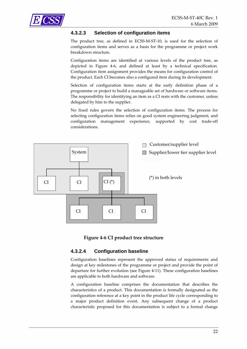
4.3.2.3 Selection of configuration items The product tree, as defined in ECSS‐M‐ST‐10, is used for the selection of configuration items and serves as a basis for the programme or project work breakdown structure.
Configuration items are identified at various levels of the product tree, as depicted in Figure 4‐6, and defined at least by a technical specification. Configuration item assignment provides the means for configuration control of the product. Each CI becomes also a configured item during its development.
Selection of configuration items starts at the early definition phase of a programme or project to build a manageable set of hardware or software items. The responsibility for identifying an item as a CI rests with the customer, unless delegated by him to the supplier.
No fixed rules govern the selection of configuration items. The process for selecting configuration items relies on good system engineering judgment, and configuration management experience, supported by cost trade‐off considerations.
System
CI CI CI (*)
CI CI CI
Customer/supplier level
Supplier/lower tier supplier level
(*) in both levels
Figure 4‐6 CI product tree structure
4.3.2.4 Configuration baseline Configuration baselines represent the approved status of requirements and design at key milestones of the programme or project and provide the point of departure for further evolution (see Figure 4‐11). These configuration baselines are applicable to both hardware and software.
A configuration baseline comprises the documentation that describes the characteristics of a product. This documentation is formally designated as the configuration reference at a key point in the product life cycle corresponding to a major product definition event. Any subsequent change of a product characteristic proposed for this documentation is subject to a formal change

ECSS‐M‐ST‐40C Rev. 1 6 March 2009
23
procedure involving all the actors and disciplines concerned before it can be incorporated.
During the life cycle of the product, configuration baselines are elaborated in the following sequence:
• Mission objective baseline (MOB) is established at PRR based on the approved functional specification. This baseline establishes the purpose of the system, its associated constraints and environments, the operational and performances capabilities for each phase of its life cycle, and the permissible flexibility.
• Functional configuration baseline (FCB) is established at SRR based on the approved system technical specification. This baseline establishes the system’s characteristics in terms of its technical requirements, as well as the criteria and corresponding levels of qualification and acceptance.
• Development configuration baseline (DCB) is established at PDR based on approved technical specifications (TS). This baseline establishes the product’s characteristics in terms of technical requirements and design constraints, as well as their verification conditions.
NOTE FCB and DCB are also named “Requirements baselines” in different standards.
• Design baseline (DB) is established at CDR based on the approved design documentation.
• Product configuration baseline (PCB) is established at FCV/PCV for serial production, or QR/AR for prototypes based on the approved set of documents containing all the functional and physical characteristics required for production, acceptance, operation, support and disposal.
The log book, as in ECSS‐Q‐ST‐20, is established at successful completion of the acceptance review and is maintained during the utilization and disposal phases.
Details relevant to the configuration management approach during these phases are provided in clause 4.3.7.
4.3.2.5 Identification marking Each item, H/W and S/W is uniquely identified by a specific identification code. The identification code is assigned to a product to distinguish it during its entire life. The rules for the identification coding system are established in the CM plan.
A configured H/W item is identified by a part number and, if necessary, a serial or lot number such that every single item has a unique identifier. In this context, bulk material is treated as a part. A configured S/W item is identified by a unique code and version number. When the configured item is a configuration item, its identification also includes a CI identifier. These different product identification data are applied on the product itself or, when not possible, linked to the product.

ECSS‐M‐ST‐40C Rev. 1 6 March 2009
24
4.3.2.6 Digital file and media identification Configuration identification also provides the means for maintaining traceability from a product to its design definition data resident in an electronic database (digital files).
Such data, represented by digital files, are composed by a variety of subset data, which are merged in a controlled manner in order to represent the product design definition concerned in the intended configuration.
Configuration management for these sets of data and their integration into a complete product design definition is an existing application of software CM processes (e.g. library management).
Digital files defining the configuration characteristics of a product item are therefore subject to the same configuration management principles applicable to configuration documentation.
The application of configuration identification rules to digital data are applicable for
• digital data identification,
• digital data storage,
• maintenance of digital data relating to the product,
• version control of digital data and the related change management process,
• controlled access to digital data, and
• digital data transmittal.
4.3.3 Configuration control
4.3.3.1 Overview Configuration control, as depicted in Figure 4‐7, is the process for controlling the evolution of, or departures from agreed baselines. It includes the preparation, justification, evaluation, disposition and implementation of engineering and contractual changes, deviations and waivers.

ECSS‐M‐ST‐40C Rev. 1 6 March 2009
25
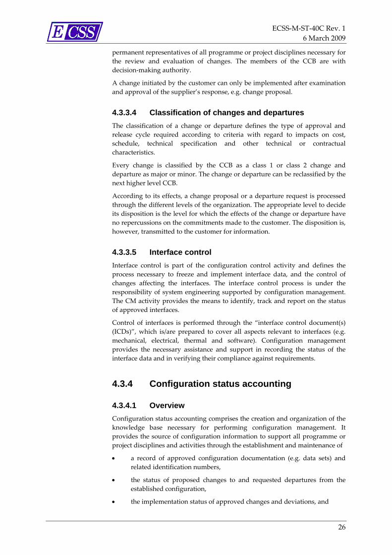
Figure 4‐7 Configuration control
4.3.3.2 Change procedure Configuration control ensures that all changes, deviations and waivers to agreed configuration baselines, including their released and approved documentation are processed and controlled in a traceable manner.
The configuration control process ensures that the following activities are covered:
• prevention of changes affecting degradation of product capability;
• involvement of all actors in the concerned analysis and decision process of changes;
• control that authorized changes or deviation are implemented, verified and recorded;
• prevention of the implementation of unauthorized changes or deviations.
Change control procedures are applied following the establishment of the first baseline.
All released baseline documentation, thereafter, is subject to configuration control, including submission to the customer for higher‐level approval or review, as necessary. As such, no formal change can be generated without an approved baseline.
A change can be either
• initiated by the customer (e.g. evolution of requirements) followed by a reply from the supplier within a defined time limit, or
• proposed by the supplier (e.g. self initiated improvement of design) followed by a response from the customer.
4.3.3.3 Configuration control board Configuration control boards (CCB) are established at each project level as the relevant authority for all changes. The CCB is convened by the configuration manager in agreement with the project manager. The CCB consists of
ECSS‐M‐ST‐40C Rev. 1 6 March 2009
26
permanent representatives of all programme or project disciplines necessary for the review and evaluation of changes. The members of the CCB are with decision‐making authority.
A change initiated by the customer can only be implemented after examination and approval of the supplier’s response, e.g. change proposal.
4.3.3.4 Classification of changes and departures The classification of a change or departure defines the type of approval and release cycle required according to criteria with regard to impacts on cost, schedule, technical specification and other technical or contractual characteristics.
Every change is classified by the CCB as a class 1 or class 2 change and departure as major or minor. The change or departure can be reclassified by the next higher level CCB.
According to its effects, a change proposal or a departure request is processed through the different levels of the organization. The appropriate level to decide its disposition is the level for which the effects of the change or departure have no repercussions on the commitments made to the customer. The disposition is, however, transmitted to the customer for information.
4.3.3.5 Interface control Interface control is part of the configuration control activity and defines the process necessary to freeze and implement interface data, and the control of changes affecting the interfaces. The interface control process is under the responsibility of system engineering supported by configuration management. The CM activity provides the means to identify, track and report on the status of approved interfaces.
Control of interfaces is performed through the “interface control document(s) (ICDs)”, which is/are prepared to cover all aspects relevant to interfaces (e.g. mechanical, electrical, thermal and software). Configuration management provides the necessary assistance and support in recording the status of the interface data and in verifying their compliance against requirements.
4.3.4 Configuration status accounting
4.3.4.1 Overview Configuration status accounting comprises the creation and organization of the knowledge base necessary for performing configuration management. It provides the source of configuration information to support all programme or project disciplines and activities through the establishment and maintenance of
• a record of approved configuration documentation (e.g. data sets) and related identification numbers,
• the status of proposed changes to and requested departures from the established configuration,
• the implementation status of approved changes and deviations, and

ECSS‐M‐ST‐40C Rev. 1 6 March 2009
27
• the actual configuration of all units of configured items being in the operational inventory.
Together these comprise the configuration status accounting report.
4.3.4.2 As-designed and as-built data list The CIDL is a document generated for reporting the current design status of each product configuration item. This document is provided at the PDR with the establishment of the development configuration baseline and maintained during the lifecycle of the product CI.
The CIDL itself and the data included serve as a point of departure for the control of subsequent performance, design and build changes.
When software product CIs are involved, a software configuration file is also prepared in order to provide more extensive information relevant to installation and use of the described product.
The CIDL is the source for the preparation of the ABCL, which is the document used to report the as‐built and as‐tested status for each serial number of product CI.
4.3.5 Configuration verification Configuration verification is the process to verify the current configuration status of the analyzed product and results in the establishment of configuration baselines as defined in clause 4.3.2.5. This activity is performed during programme or project reviews, which are defined in ECSS‐M‐ST‐10 together with their objectives.
At the end of each review, the documents and data sets that identify the current configuration baseline are updated to be in conformance with the review dispositions and then presented to the customer for approval.
4.3.6 Configuration management process audit The effectiveness of the configuration management system is measured by audits to verify the proper application of configuration management requirements during the life cycle of the product as specified by the customer.
Audits are conducted in accordance with requirements defined in ECSS‐M‐ST‐10.
4.3.7 Configuration management approach for operational phase
The activities performed by configuration management during the operational phase (phase E and F of a project) are those required by the set of reviews established by ECSS‐M‐ST‐10.
If necessary, a dedicated CM plan can be prepared to describe the process to meet the objectives of the operational phase.
ECSS‐M‐ST‐40C Rev. 1 6 March 2009
28
During this phase the functions of CM are continued from previous project phases.
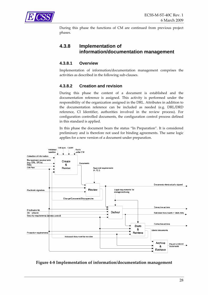
4.3.8 Implementation of information/documentation management
4.3.8.1 Overview Implementation of information/documentation management comprises the activities as described in the following sub‐clauses.
4.3.8.2 Creation and revision During this phase the content of a document is established and the documentation reference is assigned. This activity is performed under the responsibility of the organization assigned in the DRL. Attributes in addition to the documentation reference can be included as needed (e.g. DRL/DRD reference, CI Identifier, authorities involved in the review process). For configuration controlled documents, the configuration control process defined in this standard is applied.
In this phase the document bears the status “In Preparation”. It is considered preliminary and is therefore not used for binding agreements. The same logic applies for a new version of a document under preparation.
Figure 4‐8 Implementation of information/documentation management

ECSS‐M‐ST‐40C Rev. 1 6 March 2009
29
4.3.8.3 Review
4.3.8.3.1 Review activity
When the document is complete, it is submitted for review and approval as required. The review process is then initiated as specified within the CM Plan.
In this phase the document bears the status “In Review”.
The same restriction regarding its use applies as for the creation/revision phase, and is therefore not to be used for binding agreements. The review authority either confirms that the content complies with the applicable requirements, or states the identified discrepancies together with the proposed resolution. In the latter case, the document is returned to the creation/revision phase for incorporation of comments and resolution of the identified discrepancies.
During the review process a document can be “withdrawn” (if it did not pass the review cycle and is maintained or traced for historical purposes only) or get the status “obsolete” or “superseded”(when it has been released but superseded by a new document).
4.3.8.3.2 Approval and release
Approval can be given either by electronic signature or by process as defined in the CM Plan.
Electronic signature or approval by process ensures that
a. the document has not been modified after its approval (i.e. integrity), and
b. the author cannot deny his responsibility for the content of the document (i.e. non‐repudiation).
At the end of the review phase once all required approvals are given, the document reaches the status “Released”.
Once released the document is valid for use and therefore ready for distribution. After the document is released, any modification to the document implies a new version.
4.3.8.4 Delivery Documents are delivered in line with the procedures defined by the CM Plan taking into account the level of confidentiality applicable to each document. The status of the document is not changed during delivery.
Documents are delivered using “Technical Data Package (TDP)” format which defines the way to exchange content files and their related metadata and to structure them within folders.
The TDP is a ZIP file containing document file(s) and metadata describing these documents. Metadata used in the TDP are a subset of the ISO 10303 STEP AP232 metadata added by some specific metadata defined in Annex L.
The metadata are stored in the ʺdatapackage.xmlʺ file. See Figure 4‐9.

ECSS‐M‐ST‐40C Rev. 1 6 March 2009
30
Figure 4‐9 TDP contents
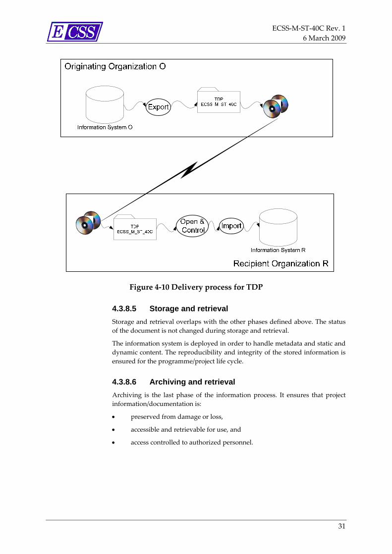
The delivery process is summarized in the following diagram. The main steps are:
a. the originating organization “exportsʺ content files and metadata from its Information System (IS) to TDP;
b. the originating organization provides TDP to recipient organization via e.g. e‐mail, ftp, CD‐ROM;
c. the recipient organization ʺopens and controlsʺ the compliance of the TDP;
d. the recipient organization ʺimportsʺ the TDP into its Information System.
ECSS‐M‐ST‐40C Rev. 1 6 March 2009
31
Figure 4‐10 Delivery process for TDP
4.3.8.5 Storage and retrieval Storage and retrieval overlaps with the other phases defined above. The status of the document is not changed during storage and retrieval.
The information system is deployed in order to handle metadata and static and dynamic content. The reproducibility and integrity of the stored information is ensured for the programme/project life cycle.
4.3.8.6 Archiving and retrieval Archiving is the last phase of the information process. It ensures that project information/documentation is:
• preserved from damage or loss,
• accessible and retrievable for use, and
• access controlled to authorized personnel.

ECSS‐M‐ST‐40C Rev. 1 6 March 2009
32
Figure 4‐11 Project phases and baseline definitions

ECSS‐M‐ST‐40C Rev. 1 6 March 2009
33
5 Configuration management requirements
5.1 General In this ECSS Standard, in order to facilitate reading and traceability, the paragraph numbering in this clause is consistent with the paragraph numbering of clause 4.
5.2 Management and planning
5.2.1 Configuration management plan
5.2.1.1 General a. Each supplier shall provide for customer’s approval a configuration
management plan in conformance with Annex A, configuration management plan DRD.
b. Internal procedures called up in the configuration management plan shall be made available for customer review upon request.
5.2.1.2 Information security a. Information shall only be classified when imposed by national or
international laws, or by programme / project requirements, or to protect company / organizational interests.
b. Information shall be protected against unauthorized access and according to the confidentiality classes.
c. The information access and confidentiality classes shall be agreed between customer and supplier.
d. The list of authorized personnel having access to the information system shall be agreed between the customer and supplier.
5.2.1.3 Classification a. Customer and suppliers shall indicate within the CM Plan the
classification classes to be applied and the documentation set affected.
b. Classification classes shall be clearly indicated on the documents.

ECSS‐M‐ST‐40C Rev. 1 6 March 2009
34
c. Classified information shall be accessible only to persons having the right authorizations and privileges.
d. Classified information shall be used only in a secure environment or location.
NOTE For example: area limited in access.
e. The assigned classification shall be maintained only as long as the information requires protection.
f. The responsibility for classifying information shall rest solely with the originating organization.
g. Destruction of classified information and the method used for destruction shall be recorded.
h. Classified information shall be downgraded or declassified only with the prior written consent of the originating organization.
5.2.2 Configuration management interfaces a. Configuration management processes shall interface with project
management and planning, taking into account the contractual provision and schedule organization for the definition and phasing of CM activities.
b. Configuration management processes shall interface with engineering and product assurance for agreeing the technical information for which the CM process controls.
c. Configuration management processes shall interface with IDM for defining rules for documentation identification and processing, control and distribution.
d. Configuration management processes shall interface with IDM to support Engineering, Product Assurance (PA), manufacturing and production by providing the information/documentation in time and in adequate format for their activities.
e. Configuration management processes shall interface with logistic and maintenance processes to determine up to which level of product the CM process shall be applied.
5.3 Implementation of configuration management
5.3.1 Configuration identification
5.3.1.1 Configuration item a. A configuration item shall be defined in relation to the following criteria:
1. by its complete design documentation if it is developed for space application;

ECSS‐M‐ST‐40C Rev. 1 6 March 2009
35
2. by its procurement specification, including the list of its performances and interface characteristics, if it is an off‐the‐shelf (OTS) product;
3. by reference to its governing standard, if it is a product defined by a standard.
5.3.1.2 Configuration item selection a. Based on customer input, the supplier shall identify in the product tree,
the configuration items and their applicable specifications, and agree these with its customer.
NOTE 1 Detailed guideline for selecting configuration items is given in Annex K.
NOTE 2 For product tree see ECSS‐M‐ST‐10.
b. The supplier shall prepare the list of configuration items it supplies and keep this under configuration control in conformance with Annex B, configuration item list DRD.
c. The configuration item list shall be provided at the PDR for customer approval.
5.3.1.3 Configuration baseline a. The supplier shall agree with its customer which documentation shall
constitute each configuration baseline. NOTE 1 For hardware products, configuration baselines
include the following documents:
• the functional specification;
• the technical specification;
• general specifications (e.g. environment, radiation, design rules, interfaces, and PMP);
• procurement specification for OTS items;
• standardization document;
• engineering drawings (e.g. interface control drawings, parts and assembly drawings, and installation drawings) and associated lists;
• the interface control document;
• the configuration items data list;
• the installation/user/operating/maintenance manual;
• test specifications;
• test procedures;
• applicable engineering changes;
• applicable deviations.

ECSS‐M‐ST‐40C Rev. 1 6 March 2009
36
NOTE 2 For software products, configuration baselines include the following documents:
• software system technical specification, when applicable;
• software requirements document (SRD);
• software design document;
• interface control document;
• software configuration file (SCF) (including the source code listing);
• software release document;
• the installation/user/operating/maintenance manual;
• the configuration description of the development tools (e.g. compilers, and linkers);
• software validation testing specifications;
• software test procedures;
• maintenance procedures;
• applicable engineering changes;
• applicable deviations.
b. The baseline documentation shall reflect the actual configuration of the product, at any given point of the product life cycle.
5.3.1.4 Baseline establishment a. Baselines shall be established at the conclusion of each technical review
as the starting point for configuration control as defined below:
1. The starting point of configuration control for functional specification is at conclusion of the preliminary requirements review (PRR), establishing the mission objective baseline.
2. The starting point of configuration control for system technical specifications (TS) is at conclusion of the system requirements review (SRR), establishing the functional configuration baseline.
3. The starting point of configuration control for product technical specifications (TS) and ICDs is at conclusion of the preliminary design review (PDR), establishing the development configuration baseline. This represents freezing of performance and design requirements and control of developmental models.
NOTE For example: EM, EQM, and mock‐ups.
4. The starting point of configuration control of the product design for PFM/FM model manufacturing for qualification purposes is at the conclusion of the CDR, establishing the design baseline.
5. The starting point of configuration control of the qualified product design for serial production is at the conclusion of the PCV, or for

ECSS‐M‐ST‐40C Rev. 1 6 March 2009
37
prototype(s) at QR/AR, establishing the product configuration baseline.
6. The starting point of configuration control of the user manual is at conclusion of the qualification review (QR).
7. The starting point for issue and maintenance of the log book is at conclusion of the acceptance review (AR).
b. The supplier shall maintain the configuration baselines through out the programme or project life cycle.
5.3.1.5 Identification marking a. Any product item shall be identified to guarantee its traceability
throughout the programme or project life cycle.
b. For developed hardware CI, the following information shall be included:
1. CI‐identifier
2. Part number
3. Serial or lot number
4. Model identifier
NOTE For example: EM, STM, and FM (not for ground systems).
5. Manufacturer identifier
6. Product name or abbreviation.
c. For developed software CIs, the following shall be included in the header:
1. CI‐identifier
2. Software identifier
3. Version and revision number
4. Release date
5. Manufacturer identifier
6. product name or abbreviation.
d. For OTS and standard products, the following information shall be included as a minimum:
1. Part number
2. Serial or lot number
3. Manufacturer identifier
4. Product name or abbreviation.
e. All product items, not defined as configuration item, shall be marked or labelled including the following information:
1. Part number
2. Serial or lot number, when applicable

ECSS‐M‐ST‐40C Rev. 1 6 March 2009
38
3. Manufacturer identifier.
f. All product items subject to major nonconformances shall receive supplemental identification to provide a link to the departure authorization document.
g. For media containing software, the following information shall be included as a minimum:
1. CI‐identifier;
2. S/W identifier;
3. Version and revision number;
4. Date of generation;
5. Manufacturer identifier;
6. Product name or abbreviation;
7. SCF reference including issue and date;
8. Total number of delivered media per information set (1 of ...);
9. Copy or serial number of data set.
h. When the physical dimensions of the item restricts full identification marking, the following shall apply:
1. Select a minimum set of information which uniquely identifies the items.
2. Identify on a permanent tag, if possible.
3. If permanent tag is not possible, identify on a removable tag or on the packaging.
i. The identification marking methods applied shall be compatible with the product’s operational environment.
j. The identification marking methods applied shall be defined in the configuration definition document.
k. Identification marking of software products shall be established through the hardware product where the software is resident (i.e. the firmware), or the media in which the software is stored.
5.3.1.6 Digital file and media identification a. Digital files defining configuration characteristics shall be uniquely
identified and linked to their related product configuration data.
b. The digital data files forming part of each configuration baseline shall be stored in a secure environment with controlled access.
c. Digital files composing the definition of configuration characteristics shall be maintainable throughout the life cycle of the programme or project.
d. Digital files defining the configuration characteristics shall be stored within the CM system by its native code and by a PC readable file directly generated from the native code.
NOTE For example: PDF or TIFF.

ECSS‐M‐ST‐40C Rev. 1 6 March 2009
39
e. The system shall be able to manage check‐in/check‐out, multiple versions.
f. The system shall be able to generate any current, baseline or past version of the file.
g. Distribution, delivery or publishing of the file shall be generated from the master file.
h. Paper forms of digital files shall be traceable to the master file.
i. The order of precedence between the master file and the printed documentation shall be established.
j. CAD data shall be traceable to the engineering drawing.
NOTE For example: CAD files, 3D models, and digital mock‐ups.
k. Digital data media shall be identified by the following:
1. CI identifier
2. File names
3. Version and issue
4. Date of generation
5. Generating entity
6. Total number of delivered media per information set (1 of ...).
l. The following information shall be provided together with digital data media:
1. Host system
2. Application software
3. Printer and style details
4. Special instruction for further processing of the data file.
5.3.2 Configuration control
5.3.2.1 Change procedure a. A change procedure shall be established to describe the process for
changing a configuration baseline.
b. Any change to a configuration item, in relation to an approved configuration baseline, shall be described, justified and classified by the requesting party, before submission for review and disposition.
c. Each actor shall establish a configuration control board to evaluate and approve any change to a configuration item relative to a configuration baseline.
d. Related changes of several products resulting from a common need for change shall be processed simultaneously.
ECSS‐M‐ST‐40C Rev. 1 6 March 2009
40
e. Changes related to an element common to several products shall be presented to all the concerned actors for impact assessment.
5.3.2.2 Classification of changes and departures a. A class 1 change, or a major departure, shall be approved by the
customer before its implementation.
b. A class 2 change, or a minor departure, shall be implemented after supplier approval and provided to the customer for information.
c. Customer may reclassify the class 2 proposed changes and minor departures.
d. Unplanned departures shall be classified and processed in conformance to ECSS‐Q‐ST‐10‐09.
e. Major planned departures shall be processed as for class 1 changes.
f. Minor planned departures shall be processed as for class 2 changes.
g. For planned departures from requirements or design, the supplier shall submit a request for deviation describing why the product concerned cannot meet requirements of the baselined configuration documentation.
h. The supplier shall ensure that changes or departures are approved at the level for which the effects of the change or the departure can have no repercussion on the commitments made to the customer.
i. The evaluation shall be transmitted to the customer for information.
5.3.2.3 Initiation of change a. All changes initiated by the customer shall use a change request in
conformance with Annex G, change request DRD.
b. All changes initiated by the supplier shall use a change proposal in conformance with Annex H, change proposal DRD.
5.3.2.4 Change assessment a. Both customer and supplier shall establish procedures for the analysis,
review and disposition of proposed changes.
b. The change assessment shall cover all technical, programmatic and operational impacts on all affected products for which the actor is responsible.
c. Each project actor shall assess any request or proposal for a change to a configuration baseline, which is presented to him by his customer or supplier.
5.3.2.5 Change disposition a. All changes shall be dispositioned by the configuration control board as
either:
1. approved, defining the applicability of evolution and associated implementation modes,

ECSS‐M‐ST‐40C Rev. 1 6 March 2009
41
2. rejected, with a supporting rational, or
3. deferred until additional information is provided.
5.3.2.6 Departures from configuration baseline a. The supplier shall request planned departures from requirements or
design using a request for deviation in conformance with Annex I, request for deviation DRD.
b. The supplier shall request unplanned departures from requirements or design using a request for waiver in conformance with Annex J, request for waiver DRD.
c. The configuration control board shall process deviations and waivers from baselined requirements or design when customer requirements are affected.
d. Departures shall be limited to a number of items or a period of time.
e. Deviations related to an element common to several products shall be presented to all the concerned actors for impact assessment.
5.3.2.7 Baseline and documentation update a. Configuration baselines shall be updated in conformance with the
disposition of approved changes and deviations.
b. Configuration‐controlled documents shall be revised to incorporate approved changes.
5.3.2.8 Interface control a. Each actor shall record the status of interface definition data.
b. Each actor shall ensure that all interface definition data is consistent with its product configuration.
c. The supplier shall identify and control the internal interfaces of its product and those interfaces for which he has received delegated authority.
d. Configuration management shall establish, concurrently with the system engineering, the overall organization and procedures to process and manage changes to interfaces.
e. Each actor shall clearly identify in configuration definition documentation the data subject to interface management.
5.3.3 Configuration status accounting
5.3.3.1 General a. All actors shall establish a configuration status accounting system to
record, store and retrieve the following configuration data:
1. status of the configuration baselines;

ECSS‐M‐ST‐40C Rev. 1 6 March 2009
42
2. design status of the configuration items;
3. as‐built status of accepted products;
4. status of configuration documentation and configuration data sets;
5. status of approval of changes and deviations and their status of implementation, the status of waivers;
6. status of actions derived from technical reviews and configuration verification reviews.
b. Each supplier shall provide configuration status accounting reports in conformance with Annex F, configuration status accounting reports DRD.
5.3.3.2 As-designed data list a. The supplier shall provide a configuration item data list (CIDL), in
conformance with Annex C, configuration item data list DRD, for each deliverable CI.
b. For each deliverable software CI, the supplier shall provide a software configuration file (SCF) in conformance with Annex E, software configuration file DRD.
c. A CIDL shall be available for the first design review to determine the initial configuration baseline.
d. The complete CIDL for an individual CI, model or deliverable item shall be available at project reviews.
e. Changes implemented after delivery of the product shall be incorporated in the CIDL.
f. The updated CIDL shall be provided for log‐book updating.
5.3.3.3 As-built data list a. For each deliverable serial number of CI, the supplier shall provide an
as‐built configuration data list in conformance with Annex D, as‐built configuration list DRD.
b. The ABCL shall identify the “as manufactured” and “as tested” statuses applicable to parts composing a CI.
c. Using the CIDL as a reference, any difference between the ABCL and the CIDL shall be documented in the ABCL by reference to the applicable NCR(s) or RFW(s).
5.3.4 Configuration verification
5.3.4.1 Verification of the product configuration definition a. At SRR, the functional configuration definition shall be verified against
mission objectives.
ECSS‐M‐ST‐40C Rev. 1 6 March 2009
43
b. At PDR, the development configuration definition shall be verified against the applicable technical specifications.
c. At CDR, the design definition shall be verified against the relevant design documentation.
5.3.4.2 Verification of the product configuration a. The supplier shall perform configuration verification by systematically
comparing the “as‐built” configuration of a CI with its “as designed” configuration.
b. Configuration in terms of functional and performance characteristics shall be verified at qualification review (QR) for prototype or proto‐flight production, and FCV for serial production.
c. Configuration in terms of physical and nominal performance characteristics shall be verified at AR for prototype or proto‐flight production and PCV for serial production.
5.3.5 Audit of the configuration management system
a. Each project actor shall conduct internal audits to verify the application of configuration management requirements internal to his organization.
b. Each project actor shall conduct external audits to verify the application of configuration management requirements by its lower tier suppliers, in accordance with the requirements defined in ECSS‐M‐ST‐10.
5.3.6 Configuration management approach for operational phase
a. The following product configuration related activities shall be implemented during the operational phase:
1. Preparation of a CM plan in conformance with Annex A, configuration management plan DRD, to meet the objective of the operational phase.
NOTE This requirement can be fulfilled by adapting the development phase CM plan or creating a dedicated CM plan.
2. Provisioning of, or access to development phase documents as established at product delivery.
3. Maintenance and control of ground models (i.e. engineering model and mock‐ups) supporting the flight operations to be flight representative.
4. Inventory control of flight spare parts in terms of quantity and storage location.
5. Accomplishment of product enhancement in three different ways as follows:

ECSS‐M‐ST‐40C Rev. 1 6 March 2009
44
(a) for in‐line production with no retrofit to delivered units, production changes are undertaken by normal change processing;
(b) for in‐line production with retrofitting of delivered units, retrofit changes are either carried out by the supplier on basis of contractor modification documentation; or
(c) retrofit of delivered units (no more production) by the user, on basis of a modification kit with accompanying modification instructions.
6. Design change implementation on product according to the following cases:
(a) normal change processing for in‐line production with no retrofitting of delivered product;
(b) documentation update for in‐line production with retrofitting of delivered product performed by the supplier; or
(c) modification kit with accompanying modification instructions for retrofitting by the user of the product.
5.3.7 Implementation of information/documentation management
5.3.7.1 General a. Each actor shall ensure that the information management processes and
information system are in accordance with the project needs.
b. The information system shall support the creation, collection, review, delivery, storage, retrieval and archiving of information/documentation and related data.
c. The relevant project information/documentation shall be accessible to all authorized project members.
d. The information system shall support the agreed reporting requirements.
NOTE For example: generating of document status lists, schedule reports.
e. All information/documentation released for a programme or project shall be managed electronically.
f. In case of discrepancies between electronic and paper based information the electronically stored version shall take precedence.
NOTE In case of conflict the national/European law takes precedence.

ECSS‐M‐ST‐40C Rev. 1 6 March 2009
45
5.3.7.2 Creation and revision
5.3.7.2.1 Responsibilities
a. Responsibility for the information/documentation content shall lie with the organization closest to the data source.
b. Author(s) for creating the information/documentation shall be assigned responsibility by the relevant organization.
c. The information/documentation content shall be established in accordance with the DRD which describes the document.
d. Author(s) shall always identify the reason(s) for generating a new document issue.
e. Process for revising information/documents shall involve and apply the same authorities and approval process as for previous issues.
f. During the creation phase the information/documentation shall be considered preliminary and shall not be used for binding agreements.
5.3.7.2.2 Data collection
a. All project‐related information shall be maintained within the information system.
b. Data applicable to a programme or project shall be ordered in such a way that they can be extracted from the information system and ordered according to the predefined values.
c. Metadata shall be identified and entered into the information system, containing as a minimum the terms required in Annex L.
5.3.7.2.3 Conversion to electronic format
a. In the case of paper documents, their content shall be converted to electronic format and uploaded into the information system together with its metadata.
b. The process of converting electronic content from its native format to the delivery format shall maintain visual integrity.
5.3.7.2.4 Identification
a. Each document and each document issue shall be uniquely identified.
b. Configuration management requirements shall be taken into account for documents that are part of a configuration baseline.
c. Document identification shall not contain any elements that are liable to change from an issue to another.
NOTE For example: Product Item, Configuration Item, level of approval, issue.
5.3.7.2.5 Revision
a. Changes to information/documentation shall be always justified.
b. Changes to information/documentation and their justification shall be traceable within the information /documentation.

ECSS‐M‐ST‐40C Rev. 1 6 March 2009
46
c. The updating of any configuration controlled document shall be processed according to the configuration process.
d. Once released, the integrity of any information/documentation shall be guaranteed by the information system.
5.3.7.3 Review
5.3.7.3.1 Review activity
a. Each actor shall implement a review cycle for each information/documentation item he is required to release.
b. The review cycle for classified information/documentation shall be established according to the level of classification defined for the information/documentation itself.
c. The supplier shall implement a control process to ensure that all information requiring customer or lower tier supplier signatures are submitted on time to the customer or lower tier supplier.
d. The customer shall confirm his approval or non‐approval with rationale to the relevant supplier in accordance with their business agreement.
e. The lower tier supplier shall confirm his approval or non‐approval with rationale to the relevant customer within the contractually agreed timeframe.
f. Any discrepancy raised against a document shall be provided to the originating organization in writing.
g. Information/documents shall be delivered when the review cycle has been completed and all the required approvals are obtained.
5.3.7.3.2 Approval methods by digital signature
a. Information/documentation shall be signed using digital signature.
b. The digital signature shall be in compliance with internationally recognized standards.
c. Self‐signed certificates shall not be used.
d. The digital signature shall be implemented to sign information/documentation in any electronic format.
e. The digital signature shall support multiple signing.
f. Digitally signed information shall provide indication that the information has been digitally signed.
g. A digitally signed document shall provide on the cover page an indication stating that the document has been digitally signed.
NOTE Information about digital signature is provided in Annex M (Digital signature).
5.3.7.3.3 Approval methods by process
a. Information/documentation approved by an informatics process shall clearly indicate approval in a visible manner:

ECSS‐M‐ST‐40C Rev. 1 6 March 2009
47
1. on the cover page of the electronic document file (source file or .pdf‐file);
2. as part of the information file header.
b. Actors involved in the approval loop shall be identified on approved Information/documentation.
c. The information system managing the process shall record the processing steps of approval.
d. A Log‐File of the processing steps of approval shall be generated automatically by the information system.
e. The Log‐File shall be stored together with the released information/documentation within the information system.
5.3.7.4 Delivery a. Information/documentation shall be delivered using TDP.
NOTE For details see Annex L, Technical Data Package Description.
b. Customer and Supplier shall agree upon the optional meta‐data to be exchanged.
NOTE For details see Annex L, Technical Data Package Description.
c. Based on customer input, the supplier shall provide for customer approval the method, format and schedule for the delivery of the required information.
d. The following formats shall be used for delivery:
Read‐only documents Acrobat PDF compatible format
Editable documents MS Office compatible format
Photographic images JPEG compatible format
Technical images TIFF with LZW or other lossless compression
Technical/CAD drawings DXF, 3‐D CAD file, ISO Step format
Technical Data Package TDP ZIP
NOTE Additional formats can be implemented and agreed with the customer
e. The delivery mechanism shall ensure that the information:
1. comes from a given, identified sender (guarantee of authenticity);
2. cannot be disclaimed by the sender (guarantee of non‐repudiation);
3. cannot be read by third parties during transmission (guarantee of confidentiality);
ECSS‐M‐ST‐40C Rev. 1 6 March 2009
48
4. cannot be modified by third parties during transmission (guarantee of data integrity).
NOTE Electronic mail via SMTP and file transfer via FTP cannot be used with unencrypted files, because these delivery methods do not meet the above requirements.
f. Where a concurrent environment is available, accessibility to it shall be possible by using established privileges and rules for authorized programme/project members.
5.3.7.5 Storage and retrieval a. Each actor shall ensure that the information/documentation is available
to the programme/project members throughout the entire programme/project life cycle.
b. Each actor shall store all released document issues in the information system.
c. Each actor shall store information/documentation in its native format for future update, together with metadata, throughout the programme/project life cycle.
d. Information/documentation shall be protected against environmental and accidental risks and against unauthorized access.
e. Access to classified information/documentation shall be restricted to authorized personnel.
5.3.7.6 Archiving and Retrieval a. The supplier shall define and implement an archiving solution to ensure
that project information/documentation is:
1. preserved from damage or loss,
2. accessible and retrievable for use, and
3. access controlled to authorized personnel.
b. The supplier shall agree with the customer the duration of the archiving activities.

ECSS‐M‐ST‐40C Rev. 1 6 March 2009
49
Annex A (normative) Configuration management plan - DRD
A.1 DRD identification
A.1.1 Requirement identification and source document
This DRD is called from ECSS‐M‐ST‐40, requirement 5.2.1.1a.
A.1.2 Purpose and objective The objective of the configuration management plan is to provide in a single document all elements necessary to ensure that the implementation of configuration management meets customer requirements and is commensurate with the programme or project, organization, and management structure.
A.2 Expected response
A.2.1 Scope and content
<1> Introduction a. The configuration management plan shall contain a description of the
purpose and objective prompting its preparation.
<2> Applicable and reference documents a. The configuration management plan shall list the applicable and
reference documents in support of the generation of the document.
<3> Management
<3.1> Organization
a. The configuration management plan shall describe the organizational context, both technical and managerial, within which the prescribed configuration management activities shall be implemented.

ECSS‐M‐ST‐40C Rev. 1 6 March 2009
50
b. The configuration management plan shall also describe the interface with other CM organizations (customer and supplier) and the CM relationship to other internal organization elements.
c. The configuration management plan shall also describe the interface for the information management activities.
<3.2> Responsibilities
a. The configuration management plan shall describe the allocation of responsibilities and authorities for configuration management activities to organizations and individuals within the programme or project structure.
<3.3> Policies, directives and procedures
a. Any external constraints, or requirements, placed on the configuration management plan by other policies, directives, or procedures shall be identified in this section together with the consequences of applying these to the programme or project.
<3.4> Security
a. Customer and suppliers shall indicate within the configuration management plan the classification classes to be applied and the relevant documentation set.
<4> Configuration Management
<4.1> General
a. The configuration management plan shall identify all functions and processes, both technical and managerial, required for managing the configuration of the programme or project.
b. The configuration management plan shall introduce the following, as a minimum:
1. configuration identification;
2. configuration control;
3. configuration status accounting;
4. configuration audits and reviews;
5. interface control;
6. supplier control.
<4.2> Configuration identification
a. The configuration management plan shall identify, name, and describe the documented physical and functional characteristics of the information to be maintained under configuration management control for the programme or project.
b. The configuration management plan shall describe the following, as a minimum:

ECSS‐M‐ST‐40C Rev. 1 6 March 2009
51
1. product tree establishment (System decomposition);
2. identification of configuration items, i.e. the selection process of the items to be controlled and their definitions as they evolve or are selected;
3. naming of configuration items, i.e. the specification of the identification system for assigning unique identifiers to each item to be controlled;
4. configuration baselines establishment and maintenance;
5. interface identification;
6. configuration documentation and data release procedures.
c. In case of software configuration item and where a tool is used to build its baseline, the following shall be described:
1. procedure to enter a software configuration item into a baseline;
2. procedure to configure and establish a baseline;
3. software products and records to define a baseline;
4. procedure to approve a baseline;
5. authority to approve a baseline.
d. In case software libraries are established, the following shall be identified:
1. library types;
2. library locations;
3. media used for each library;
4. library population mechanism;
5. number of identical libraries and the mechanism for maintaining parallel contents;
6. library contents and status of each item included in;
7. conditions for entering a SCI, including the status of maturity compatible with the contents required for a particular software library type;
8. provision for protecting libraries from malicious and accidental harm and deterioration;
9. software recovery procedures;
10. conditions for retrieving any object of the library;
11. library access provisions and procedures.
<4.3> Configuration control
a. The configuration management plan shall describe the configuration control process and data for implementing changes to the configuration items and identify the records to be used for tracking and documenting the sequence of steps for each change.

ECSS‐M‐ST‐40C Rev. 1 6 March 2009
52
b. The configuration management plan shall describe the following, as a minimum:
1. configuration control board functions, responsibilities, authorities;
2. processing changes;
3. change requests;
4. change proposal;
5. change evaluation;
6. change approval;
7. change implementation;
8. processing planned configuration departures (deviations);
9. processing unplanned configuration departures (product nonconformances, waivers).
<4.4> Interface control
a. The configuration management plan shall describe the process and data for coordinating changes to the programme or project configuration management items with changes to interfaces.
<4.5> Supplier control
a. For both subcontracted and acquired products (i.e. equipment, software or service), the configuration management plan shall define the process and data to flow down the CM requirements and the programme monitoring methods to control the supplier.
b. The configuration management plan shall define the process and data to incorporate the supplier developed items into programme or project configuration management and to coordinate changes to these items.
c. The configuration management plan shall also describe how the product is received, tested, and placed under configuration control.
<4.6> Configuration status accounting
a. The configuration management plan shall describe the process and data for reporting the status of configuration items.
b. The following minimum information shall be tracked and reported for each configuration management item:
1. status of the configuration baselines;
2. design status of the configuration item;
3. status of configuration documentation and configuration data sets;
4. status of approval of changes and deviations and their implementation status;
5. status of discrepancies and actions arising from technical reviews and configuration verification reviews.

ECSS‐M‐ST‐40C Rev. 1 6 March 2009
53
<4.7> Configuration verification
a. The configuration management plan shall describe the process and data to verify the current configuration status from which the configuration baselines are established.
b. The configuration management plan shall provide the description of verification plans, procedures and schedules.
c. The configuration management plan shall identify how the recording, reporting and tracking of action items and incorporation of review recommendations are maintained.
<4.8> Audits of CM system
a. The configuration management plan shall describe the process, data and schedule for configuration audits to ensure that the configuration management of the programme or project is performed.
b. As a minimum, the configuration management plan shall enable that
1. the CM process is properly defined, implemented and controlled, and
2. the configuration management items reflect the required physical and functional characteristics.
<4.9> Technical data management
a. The configuration management plan shall describe the process and data to access and maintain text and CAD files, data and software repositories, and the implementation of any PDM system.
<5> Information/documentation management
<5.1> Information identification
a. The configuration management plan shall describe the main information/documentation categories, such as management information, contractual documentation or engineering data, to be established and used throughout the programme/project life cycle.
b. The configuration management plan shall describe methods for information/document identification including versioning.
c. The configuration management plan should list the codes for companies, information types, models, subsystems, etc. which are applied specifically in the identification method or are in general use during project execution.
d. The configuration management plan shall identify the metadata structures of the main information categories.
<5.2> Data formats
a. The configuration management plan shall define for the various information categories the data formats to be used for

ECSS‐M‐ST‐40C Rev. 1 6 March 2009
54
1. content creation and update
2. distribution
3. archiving
b. The configuration management plan shall specify which format takes precedence in case a format conversion is applied.
<5.3> Processes
a. The configuration management plan shall describe the actors involved in, as well as the method and processes for, creating, collecting, reviewing, approving, storing, delivering and archiving information items.
b. The configuration management plan shall describe the handling of legacy documentation and ʺoff‐the‐shelfʺ documentation.
c. The configuration management plan shall define the information retention period.
<5.4> Information systems
a. The configuration management plan shall list the project information systems to be used for creating, reviewing, storing, delivering and archiving the main information categories
NOTE For example: ABC for schedule, and XYZ for engineering DB.
<5.5> Delivery methods
a. The configuration management plan shall describe the methods used to deliver TDPs.
<5.6> Digital signature
a. The configuration management plan shall define the procedures, methods and rules applicable to digital signatures. This comprises information about the following aspects:
1. certificate type
2. management of signature key
3. time stamping
4. signing of PDF documents
5. multiple signatures per document
<5.7> Information status reporting
a. The configuration management plan shall describe the process and content for reporting the status of information items.
b. For documentation the following attributes shall be reported as a minimum: document identification, version, title, issue date, status, and document category.

ECSS‐M‐ST‐40C Rev. 1 6 March 2009
55
<6> Schedule and resources
<6.1> Schedule
a. The configuration management plan shall establish the sequence and coordination for all the configuration management activities and all the events affecting the CM plan’s implementation.
<6.2> Resources
a. The configuration management plan shall identify the tools, techniques, equipment, personnel, and training necessary for the implementation of configuration management activities.
A.2.2 Special remarks a. The response to this DRD may be combined with the response to the
project management plan, as defined in ECSS‐M‐ST‐10.

ECSS‐M‐ST‐40C Rev. 1 6 March 2009
56
Annex B (normative) Configuration item list - DRD
B.1 DRD Identification
B.1.1 Requirement identification and source document
This DRD is called from ECSS‐M‐ST‐40, requirement 5.3.1.2b.
B.1.2 Purpose and objective The objective of the configuration item list is to provide a reporting instrument defining the programme or project items subject to configuration management process.
B.2 Expected response
B.2.1 Scope and content
<1> Introduction a. The introduction shall describe the purpose and objective of the
configuration item list.
<2> Applicable and reference documents a. The configuration item list shall list the applicable and reference
documents in support to the generation of the document.
<3> List a. The configuration item list shall contain for each configuration item (CI)
the following information:
1. identification code (derived from the product item code);
2. models identification and quantity;
3. CI name;

ECSS‐M‐ST‐40C Rev. 1 6 March 2009
57
4. CI category (developed, non‐developed);
5. CI supplier;
6. applicable specification.
B.2.2 Special remarks None.

ECSS‐M‐ST‐40C Rev. 1 6 March 2009
58
Annex C (normative) Configuration item data list (CIDL) - DRD
C.1 DRD identification
C.1.1 Requirement identification and source document
This DRD is called from ECSS‐M‐ST‐40, requirement 5.3.3.2a.
C.1.2 Purpose and objective The configuration item data list (CIDL) is a document generated from the central database giving the current design status of a configuration item (CI), at any point of time in sufficient detail, providing its complete definition.
C.2 Expected response
C.2.1 Scope and content
<1> Introduction a. The introduction shall describe the purpose and objective of the
configuration item data list.
<2> Applicable and reference documents a. The configuration item data list shall list the applicable and reference
documents in support to the generation of the document.
<3> List a. The configuration item data list shall include the following:
1. Cover sheets and scope.
2. Customer controlled documentation, including
(a) customer specifications and ICDs, and
(b) support specifications.

ECSS‐M‐ST‐40C Rev. 1 6 March 2009
59
3. Engineering or design documentation, including
(a) verification plans demonstrating compatibility with specified requirements,
(b) special instructions or procedures,
NOTE For example, transportation, integration, and handling.
(c) declared PMP lists,
(d) lower level specifications,
(e) lower level ICDs,
(f) drawings and associated lists,
(g) test specifications,
(h) test procedures, and
(i) users manual or handbook.
4. List of applicable changes not yet incorporated into the baselined documentation, and deviations (including status, directly related to the document (e.g. specification) to which the change belongs to).
5. CI number breakdown
(a) indentured breakdown by part numbers starting from the part number associated with the CI down to the lowest level of composition;
(b) quantity of each part number used on the next higher assembly;
(c) issue status of the drawings and associated lists applicable to each part number.
b. Each entry in the CIDL shall relate to the applicable model(s) of the CI and be defined by its document number, title, issue and release date.
C.2.2 Special remarks None.

ECSS‐M‐ST‐40C Rev. 1 6 March 2009
60
Annex D (normative) As-built configuration list - DRD
D.1 DRD identification
D.1.1 Requirement identification and source document
This DRD is called from ECSS‐M‐ST‐40, requirement 5.3.3.3a.
D.1.2 Purpose and objective The objective of the as‐built configuration list (ABCL) is to provide a reporting instrument defining the as‐built status per each serial number of configuration item subject to formal acceptance.
D.2 Expected response
D.2.1 Scope and content
<1> Introduction a. The introduction shall describe the purpose and objective of the as‐built
configuration list.
<2> Applicable and reference documents a. The as‐built configuration list shall list the applicable and reference
documents in support to the generation of the document.
<3> List a. The as‐built configuration list shall list all discrepancies between the
as‐designed configuration documented in the configuration item data list and the as‐built configuration documented by nonconformance reports or waivers.

ECSS‐M‐ST‐40C Rev. 1 6 March 2009
61
b. The ABCL configuration item breakdown section, obtained from the equivalent configuration item data list section, shall be completed by adding the following information:
1. serial number identification;
2. lot or batch number identification;
3. reference(s) of applicable nonconformance report(s) or request for waiver(s).
D.2.2 Special remarks None.
ECSS‐M‐ST‐40C Rev. 1 6 March 2009
62
Annex E (normative) Software configuration file (SCF) - DRD
E.1 DRD identification
E.1.1 Requirement identification and source document
This DRD is called from ECSS‐M‐ST‐40, requirement 5.3.3.2b and from ECSS‐E‐ST‐40 and ECSS‐Q‐ST‐80.
E.1.2 Purpose and objective The objective of the software configuration file is to provide the configuration status of the software configuration item. It controls its evolution during the programme or project life cycle.
The SCF is a constituent of the design definition file (as defined in ECSS‐E‐ST‐10).
E.2 Expected response
E.2.1 Scope and content
<1> Introduction a. The introduction shall describe the purpose and objective of the SCF.
<2> Applicable and reference documents a. The SCF shall list the applicable and reference documents to support the
generation of the document.
<3> Terms, definitions and abbreviated terms a. The SCF shall include any additional terms, definition or abbreviated
terms used.

ECSS‐M‐ST‐40C Rev. 1 6 March 2009
63
<4> Software configuration item overview a. The SCF shall contain a brief description of the software configuration
item.
b. For the software configuration item, the following information shall be provided:
1. how to get information about the software configuration item;
2. composition of the software configuration item: code, documents;
3. means to develop, modify, install, run the software configuration item;
4. differences from the reference or previous version;
5. status of software problem reports, software change requests, and software waivers and deviations related to the software configuration item.
<5> Inventory of materials a. The SCF shall list all physical media and associated documentation
released with the software configuration item.
NOTE Example of physical media are listings, tapes, cards and disks.
b. The SCF shall define the instructions necessary to get information included in physical media.
NOTE For example, to get files.
<6> Baseline documents a. The SCF shall identify all the documents applicable to the delivered
software configuration item version.
<7> Inventory of software configuration item a. The SCF shall describe the content of the software configuration item.
b. The SCF shall list all files constituting the software configuration item:
1. source codes with name, version, description;
2. binary codes with name, version, description;
3. associated data files necessary to run the software;
4. media labelling references;
5. checksum values;
6. identification and protection method and tool description.
<8> Means necessary for the software configuration item a. The SCF shall describe all items (i.e. hardware and software) that are not
part of the software configuration item, and which are necessary to

ECSS‐M‐ST‐40C Rev. 1 6 March 2009
64
develop, modify, generate and run the software configuration item, including:
1. items related to software development;
NOTE For example, compiler name and version, linker, and libraries.
2. build files and software generation process;
3. other software configuration items.
<9> Installation instructions a. The SCF shall describe how to install the software configuration item
version, its means and procedures necessary to install the product and to verify its installation.
<10> Change list a. This SCF shall contain the list of all changes incorporated into the
software configuration item version, with a cross reference to the affected software configuration item document, if any.
b. Changes not incorporated yet but affecting the S/W CI shall also be listed and include.
1. software problem reports;
2. software change requests and proposals;
3. contractual change notices;
4. software waivers and deviations.
<11> Auxiliary information a. The SCF shall include any auxiliary information to describe the software
configuration.
<12> Possible problems and known errors a. The SCF shall identify any possible problems or known errors with the
software configuration item version and any steps being taken to resolve the problems or errors.
E.2.2 Special remarks None.

ECSS‐M‐ST‐40C Rev. 1 6 March 2009
65
Annex F (normative) Configuration status accounting reports -
DRD
F.1 DRD identification
F.1.1 Requirement identification and source document
This DRD is called from ECSS‐M‐ST‐40, requirement 5.3.3.1b.
F.1.2 Purpose and objective The purpose of configuration status accounting reports is to provide a reliable source of configuration information to support all programme or project activities. They provide the knowledge base necessary for performing configuration management.
F.2 Expected response
F.2.1 Scope and content
<1> Introduction a. The introduction shall describe the purpose and objective of the
configuration status accounting reports.
<2> Applicable and reference documents a. The configuration status accounting reports shall list the applicable and
reference documents in support to the generation of the document
<3> Description a. The configuration status accounting reports shall contain information on:
1. Documents index and status list
(a) document identification;

ECSS‐M‐ST‐40C Rev. 1 6 March 2009
66
(b) issue and revision;
(c) issue and revision date;
(d) title;
(e) remarks;
(f) identification of obsolete documents.
2. Drawing index and status list
(a) drawing identification;
(b) issue and revision;
(c) issue and revision date;
(d) title;
(e) remarks;
(f) model applicability of the drawing.
3. Request for deviation index and status list
(a) deviation document number;
(b) issue and revision;
(c) issue and revision date;
(d) title;
(e) document or requirement affected;
(f) configuration item(s) affected;
(g) status of approval.
4. Request for waiver index and status list
(a) waiver document number;
(b) issue and revision;
(c) issue and revision date;
(d) title;
(e) document or requirement affected;
(f) NCR originating the waiver;
(g) serial number of configuration item(s) affected;
(h) status of approval.
5. Change proposal (CP) index and status list
(a) CP document number;
(b) issue and revision;
(c) issue and revision date;
(d) title;
(e) change request originating the change;
(f) configuration item(s) affected;

ECSS‐M‐ST‐40C Rev. 1 6 March 2009
67
(g) status of approval.
6. Review item discrepancies (RID) index and status list
(a) design review identification;
(b) RID identification;
(c) title of the discrepancy;
(d) affected document number and issue;
(e) affected paragraph;
(f) RID status;
(g) identification of action assigned;
(h) RID closure date;
(i) remarks.
F.2.2 Special remarks None.

ECSS‐M‐ST‐40C Rev. 1 6 March 2009
68
Annex G (normative) Change request - DRD
G.1 DRD identification
G.1.1 Requirement identification and source document
This DRD is called from ECSS‐M‐ST‐40, requirement 5.3.2.3a.
G.1.2 Purpose and objective The objective of a change request is to collect the information that formally defines a proposed programme or project change versus the existing requirements.
G.2 Expected response
G.2.1 Scope and content a. The change request shall contain the information in Table G‐1.
G.2.2 Special remarks None.

ECSS‐M‐ST‐40C Rev. 1 6 March 2009
69
Table G‐1: Change request scope and content No. Data Description
1 Organization Identification of the change request originating organization
2 Number Unique identification and register number
3 Issue Issue status of the change request
4 Date Issue date of the change request
5 Project Project under which the change request is supplied
6 Title Title of change request
7 Affected item(s) Identification of the CI(s) or PI(s) (number and name) which are affected by the change request
8 Affected document(s) Identification of the document(s) to which the change request applies (document number and issue, paragraph or requirement id)
9 Reason for change Reason why the proposed change has to made (Rationale)
10 Description of change Change description, and when requirements are affected, proposed new wording
11 Approval Names, date and signatures of the relevant authorities
12 Authorization to proceed Information on the authorization to proceed or the limit of liability, if the change has to be incorporated immediately
ECSS‐M‐ST‐40C Rev. 1 6 March 2009
70
Annex H (normative) Change proposal - DRD
H.1 DRD identification
H.1.1 Requirement identification and source document
This DRD is called from ECSS‐M‐ST‐40, requirement 5.3.2.3b.
H.1.2 Purpose and objective The objective of the change proposal is to be the vehicle for proposing a major change to an approved baselined data or the business agreement.
H.2 Expected response
H.2.1 Scope and content a. The change proposal shall contain the information in Table H‐1.
H.2.2 Special remarks None.

ECSS‐M‐ST‐40C Rev. 1 6 March 2009
71
Table H‐1: Change proposal scope and content No. Data Description
1 Organization Identification of the change proposal originating organization
2 Number Unique identification and register number
3 Issue Issue status of the change proposal
4 Date Issue date of the change proposal
5 Project Project under which the change proposal is supplied
6 Change request reference Change request reference on which the change proposal is supplied
7 Title Title of change
8 Classification Recommended classification
9 Effectivity Recommended introduction point and identification of the application range of the change
10 Change description Description of the change
11 Affected item(s) Identification of the CI or PI (number and name) affected by the change proposal
12 Affected document(s) Identification of the document(s) (e.g. number and issue, paragraph or design data) affected by the change
13 Change reason Reason for Change; Describe the rational for the change proposal approval
14 Related factors Indication on related factors (e.g. interfaces, safety) of the change: performances, interfaces, interchangeability, qualification, reliability, maintainability, safety, electrical and mechanical parameters, material or processes, parts, testing, ground segment, GSE and tooling, user documentation, cost, schedule.
15 Effect Estimated influences on business agreement provisions
16 Price Detailed cost identification and overall summary price of the change
17 Schedule effects Effects on schedule
18 Limitation of use Regarding the intended use
19 Initiator approval Names, date and signatures of the relevant authorities
20 Customer approval Names, date and signatures of the relevant authorities

ECSS‐M‐ST‐40C Rev. 1 6 March 2009
72
Annex I (normative) Request for deviation - DRD
I.1 DRD identification
I.1.1 Requirement identification and source document
This DRD is called from ECSS‐M‐ST‐40, requirement 5.3.2.6a.
I.1.2 Purpose and objective The objective of the request for deviation is to be the vehicle for requiring and agreeing the departure from a customer’s requirement that is part of an approved configuration baseline.
I.2 Expected response
I.2.1 Scope and content a. The request for deviation shall contain the information in Table I‐1.
I.2.2 Special remarks None.

ECSS‐M‐ST‐40C Rev. 1 6 March 2009
73
Table I‐1: Request for deviation scope and content Id Data Description
1 Organization Identification of the request for deviation originating organization
2 Number Unique identification and register number
3 Issue Issue status of the request for deviation
4 Date Issue date of the request for deviation
5 Classification Recommended classification (i.e. major or minor)
6 Project Project under which the nonconforming item is supplied
7 Business agreement Business agreement identification under which the nonconforming item is supplied
8 Order Order number under which the nonconforming item is supplied
9 Originator site Location of the request for deviation originator
10 Item designation Identification of the nonconforming item per name and number, according to its configuration item data list
11 Affected item(s) Identification of the CI(s) (number and name) affected by the deviation
12 Effectivity Effectivity of the deviation by model or serial number
13 Affected document(s) Identification of the document(s) to which the item does not conform (document number and issue, paragraph or requirement id)
14 Short description Title or short description of the request for deviation
15 Detailed description Description of the deviation from the relevant requirement or design feature
16 Reason for request Reason why the proposed deviation can be accepted (rationale)
17 Adverse effects Item characteristics affected by the deviation
18 Approval Decision, names, date and signatures of the relevant authorities

ECSS‐M‐ST‐40C Rev. 1 6 March 2009
74
Annex J (normative) Request for waiver - DRD
J.1 DRD identification
J.1.1 Requirement identification and source document
This DRD is called from ECSS‐M‐ST‐40, requirement 5.3.2.6b.
J.1.2 Purpose and objective: The objective of the request for waiver is to be the vehicle for requiring and agreeing to the use or the delivery of a product that does not conform to its approved product configuration baseline.
J.2 Expected response
J.2.1 Scope and content a. The request for waiver shall contain the information in Table J‐1.
J.2.2 Special remarks None.

ECSS‐M‐ST‐40C Rev. 1 6 March 2009
75
Table J‐1: Request for waiver scope and content Id Data Description
1 Organization Identification of the request for waiver originating organization
2 Number Unique identification and register number
3 Issue Issue status of the request for waiver
4 Date Issue date of the request for waiver
5 Project Project under which the nonconforming item is supplied
6 Business agreement Business agreement identification under which the nonconforming item is supplied
7 Order Order number under which the nonconforming item is supplied
8 Originator site Location of the request for waiver originator
9 Item designation Identification of the nonconforming item per name and number, according to its configuration item data list
10 Affected item(s) Identification of the CI (number and name) affected by the waiver
11 Effectivity Model or serial number (or batch / lot number) of the nonconforming item(s)
12 Affected document Identification of the document(s) (number and issue, paragraph or design data) to which the item does not conform
13 Short description Title or short description of the request for waiver (consistent with the title of the related nonconformance report)
14 Detailed description Description of the nonconformity, supported by sketches and attachments as appropriate
15 Reason for request Reason why the proposed nonconformity can be accepted (Rationale)
16 NCR Identification number of the nonconformance report related to the request for waiver
17 NRB Identification of the minutes of meeting of the nonconformance review board which decided to raise the request for waiver
18 Adverse effects Item characteristics affected by the nonconformity
19 Limitation of use Regarding the intended use
20 Classification Major or minor as per the classification criteria
21 Approval Decision, name, date and signature of the relevant authorities

ECSS‐M‐ST‐40C Rev. 1 6 March 2009
76
Annex K (informative) Configuration item selection
K.1 General The selection of configuration items (CI) is a management decision based on experience and good judgment. Therefore, this annex exposes the risk in selecting too many or too few items, and provides a check‐list to be used to help the selection process.
K.2 Effects of selecting too many configuration items Too many CIs can result in effects hampering visibility and management rather than improving it. These effects include:
• increased administrative burden in preparing, processing, and status reporting of related documentation, which tends to be multiplied by the number of CIs; or
• increased development time and cost as well as possibly creating an inefficient design.
Possible increase in management effort, difficulties in maintaining coordination and unnecessary generation of paper work or files.
K.3 Effects of selecting too few configuration items Too few configuration items can result in decreasing management visibility and progress assessment, increasing cost and difficulties in logistics and maintenance.
When the lowest level designated CI is a complex item (e.g. implementing unrelated functions, containing both hardware and software components), the following can result:
• the potential for reuse of the CI, or portions of the CI is diminished;
• re‐procurement of the CI and components is complicated;
• potential re‐procurement sources are limited;
• formal testing of critical capabilities may be delayed or made more difficult;
• the inability to account for the deployment of a CI whose component parts are disbursed to different locations;

ECSS‐M‐ST‐40C Rev. 1 6 March 2009
77
• difficulty in addressing the effectiveness of changes and retrofit actions, particularly when there are different quantities or separately deliverable components;
• increased complexity in managing and accounting for common assemblies and components;
• loss of identity through separation of affected portions of a CI during operational or depot maintenance or modification installation activity;
• inability to control individual, but identical, remove or replace items when CI identification and control is set at too high a level;
• loss of operational use of one function because of maintenance of another function within the same CI.
K.4 Configuration item selection check-list The following list of questions is proposed to help the selection process of CIs.
If most of the questions can be answered with YES, then the item is a good candidate for being a CI. On the contrary, if most of the questions can be answered with NO, then the item is not a good candidate. If the questions can be answered with approximately equal numbers of YES’s and NO’s, additional judgment is needed.
a. Is the product critical from a safety, schedule or financial point of view?
b. Will the product require development of a new design or a significant modification to an existing design?
c. Does the product incorporate new or unproven technologies?
d. Does the product have an interface with hardware or software developed under another contract?
e. Is the item required for logistic support or activity?
f. Do all components of the product have common mission, installation and deployment requirements, common testing and acceptance?
g. Does the product have interdependent functions?
h. Does the product have reconfiguration capability?
i. Is it, or does it have the potential (schedule or location) to be designated for separate procurement?
j. Can (or must) the item be independently tested?
k. Is it readily identifiable with respect to size, shape and weight?
l. With respect to form, fit or function, does it interface with other CIs whose configuration is controlled by other entities?
m. Is there a requirement to know the exact configuration and status of changes to it during its life cycle?
n. Does the item have separate mission, training, test, maintenance and support functions, or require separately designated versions for such purposes?
ECSS‐M‐ST‐40C Rev. 1 6 March 2009
78
Annex L (informative) Technical data package description
L.1 Scope and content This annex describes the approach, the relevant steps to create a TDP and the semantics of the metadata model.
The TDP can be created by using stand alone tools which allow creation of TDP by picking up files from hard disk (in this case, metadata are retyped manually), or by IS integrated tools which allow creation of the TDP from files and metadata already stored in the IS.
In both cases, a mapping between terms in this standard (see column 1 of Table L‐1 to Table L‐5) and the company terminology needs to be performed.
When using IS integrated tools, a second mapping between terms in this standard and the IS internal data structure (e.g. columns of the relational database of the IS) needs to be performed, and a connector (export or import) that is compliant with the requirements of clause 5.3.7.4 is implemented.
L.2 Steps to create an TDP a. Create an XML document (called datapackage.xml) containing tags and
values about documents to exchange, in the order defined by the ecss_m_st_40.xsd XML Schema. (See XML Schema on ECSS website http://www.ecss.nl).
b. Include the document content files and the datapackage.xml file inside a zip file.
L.3 Detailed TDP ZIP file definition: a. The TDP ZIP file contains:
⎯ The Content file(s) (in the root directory or in any folder of the zip file)
⎯ Only one datapackage.xml file in the \META‐INF folder.
as shown in the following Figure L‐1:

ECSS‐M‐ST‐40C Rev. 1 6 March 2009
79
Figure L‐1 TDP ZIP file
b. The datapackage.xml file is ʺXML validʺ i.e. it is structurally compliant with the grammar defined by the ecss_m_st_40c.xsd XML Schema. (See XML Schema on ECSS website http://www.ecss.nl).
c. The values contained in the datapackage.xml file are semantically compliant with Table L‐1 to Table L‐6.
d. Each content file is named as follows: REFERENCE_C{_I}{_[VOL]}.ext Where:
⎯ REFERENCE mandatory (REFERENCE being the identifying number of the document)
⎯ _C mandatory (C being the change level)
⎯ _I if relevant (I being the issue level)
⎯ _[VOL] mandatory if the ʺnumber of volumeʺ > 1 (VOL being the volume number in the case of several files attached to the same reference/change_level/issue_level
e. The file path of a content file within the ZIP archive relative to the meta‐inf/datapackage.xml file is stored inside the “context_file_name” implementation field.
L.4 In the following TDP‐ZIP archive file of Figure L‐2, the content file ʺDSI‐SP‐SC‐2006‐2524_01_00.docʺ is stored in the ʺ\GDOC_DOCʺ folder of the ʺDSI‐SP‐SC‐2006‐2524.doc.zipʺ file.

ECSS‐M‐ST‐40C Rev. 1 6 March 2009
80
Figure L‐2: ZIP archive
In the associated ʺdatapackage.xmlʺ file which is in the ʺ\meta‐infʺ folder, the ʺcontext_file_nameʺ field is filled as follow: …<entry_file context_file_name=ʺ..\GDOC_DOC\DSI‐SP‐SC‐2006‐2524_01_00.docʺ native_format_file_name=ʺMy OriginalDocName.docʺ/>
L.5 Semantics of the metadata model The metadata model is defined by an XML schema tree, see Figure L‐3.
Figure L‐3: XML schema tree
The top level branches shown are as follows:
a. data_package: root of the metadata model (See Table L‐1)
1. dde_definition_exchange:
(a) dde_properties: metadata related to the whole TDP (See Table L‐2).

ECSS‐M‐ST‐40C Rev. 1 6 March 2009
81
(b) item_properties: metadata to build virtual folders. Each item can have many elements (See Table L‐3).
(c) elements_properties: metadata to describe a file (See Table L‐4).
b. database: persons and companies that are linked to elements (See Table L‐5).
L.6 Data Tables description Table L‐1 to Table L‐5 describe the final blocks of the previous tree (defined by the ecss_m_st_40.xsd XML Schema).
They also provide the semantics of each term with the corresponding ISO definition if any.
NOTE These tables are given to ease human understanding of the metadata model. However, only the ecss_m_st_40.xsd XML Schema is applicable (see clause 5.3.7.4c).
The column ʺISO 10303 AP‐232 Definitionʺ contains the ISO definition. If specific comments in this standard alter the ISO definition, they are written inside a grey box.
In order to locate precisely the blocks in the XML Schema tree, the full XML path is given above each group of terms using XPATH syntax (See http://www.w3.org/TR/xpath).
The mandatory terms are enclosed inside asterisks and written bold.
Multiple terms relating to the same parent term are separated by dashed lines.
Table L‐6 provides additional information necessary to the comparison of terms used in Table L‐1 to Table L‐5.

ECSS‐M‐ST‐40C Rev. 1 6 March 2009
82
Table L‐1: data_package
ECSS‐M‐ST‐40 term Designation ISO 10303 AP‐232 Definition Your mapping Example
/data_package
* schemaVersion * Version of the XML Schema
Specific ECSS‐M‐ST‐40 (New)
Version of the XML Schema, the XML file respects
2.3 2.3
This table describes the root of the data model
Table L‐2: data_definition_exchange
ECSS‐M‐ST‐40 term Designation ISO 10303 AP‐232 Definition Your mapping Example
/data_package/data_definition_exchange/dde_properties/dde_identification/
* identifying_number * Data package reference
The identifying_number specifies an identification number for the specific group of product information of interest as issued by the Design_activity.
NOTE The identifying_number may be an alphanumeric.
A5‐TDP‐11000‐0001‐A‐DLA‐FRE
date_of_transfer (date, specific_time)
Data Package creation date
The date_of_transfer specifies the date and time when the responsible activity initiated the transfer of the Data_definition_exchange. The date_of_transfer need not be specified for a particular Data definition_‐ exchange_header.
date=2004‐11‐15 specific_time=23:59:59.99999+02:00
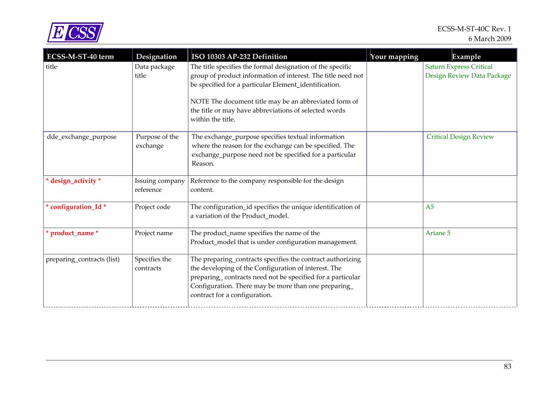
ECSS‐M‐ST‐40C Rev. 1 6 March 2009
83
ECSS‐M‐ST‐40 term Designation ISO 10303 AP‐232 Definition Your mapping Example title Data package
title The title specifies the formal designation of the specific group of product information of interest. The title need not be specified for a particular Element_identification.
NOTE The document title may be an abbreviated form of the title or may have abbreviations of selected words within the title.
Saturn Express Critical Design Review Data Package
dde_exchange_purpose Purpose of the exchange
The exchange_purpose specifies textual information where the reason for the exchange can be specified. The exchange_purpose need not be specified for a particular Reason.
Critical Design Review
* design_activity * Issuing company reference
Reference to the company responsible for the design content.
* configuration_Id * Project code The configuration_id specifies the unique identification of a variation of the Product_model.
A5
* product_name * Project name The product_name specifies the name of the Product_model that is under configuration management.
Ariane 5
preparing_contracts (list) Specifies the contracts
The preparing_contracts specifies the contract authorizing the developing of the Configuration of interest. The preparing_ contracts need not be specified for a particular Configuration. There may be more than one preparing_ contract for a configuration.

ECSS‐M‐ST‐40C Rev. 1 6 March 2009
84
ECSS‐M‐ST‐40 term Designation ISO 10303 AP‐232 Definition Your mapping Example contract_number The contract_number specifies the contract number used to
reference the contract.
NOTE The contract number may be an alphanumeric identification.
contract_data_requirements_list
The contract_data_requirements_list specifies the contract data requirement list clause or contract work listing number that authorizes, specifies, and regulates the formal agreement between two or more parties. The contract data requirements list is part of the contract. The contract_data_requirements_list need not be specified for a particular contract.
data_item_description_identification
The data_item_description_identification specifies a specific set of data or system products that are referenced within a contract. The data_item_description_identification need not be specified for a particular contract.
distribution_authorizations (list)
Specifies the distribution notice (allowed persons distribution)
The distribution_authorizations specifies the allowable circulation of information that is applicable to the Configuration. The distribution_authorizations need not be specified for a particular Configuration. There may be more than one distribution_authorizations for a Configuration.
security_identifications Specifies the security levels of the data package
The security_identifications specifies the security or sensitivity of the Configuration and its contents. The security_identification need not be specified for a particular Configuration. There may be more than one security_identifications for a Configuration.

ECSS‐M‐ST‐40C Rev. 1 6 March 2009
85
ECSS‐M‐ST‐40 term Designation ISO 10303 AP‐232 Definition Your mapping Example item_classification The item_classification specifies the security level or
sensitivity level of the Tdp_element. The security classification is assigned by the originator based on predetermined criteria.
title_security_classification The title_security_classification specifies the security level or sensitivity of the title of the Tdp_element. The security classification is assigned by the originator based on predetermined Government or commercial criteria restricting the title or nomenclature used within the title. The title_security_classification need not be specified for a particular Security_classification.
classification_date The classification_date specifies the date the item was given the item_classification. The classification_date need not be specified for a particular Security_classification.
EXAMPLE A radar absorbing material specification is classified on the date the specification is created.
declassification_date The declassification_date specifies the date the item was given the item_classification. The declassification_date need not be specified for a particular security_classification.
EXAMPLE The secret performance specifications to a retired fighter jet is declassified on this date.
release_authorizations (list) Identifies the company and person that has authenticated data package contents
The release_authorizations specifies the originating system sources that have authenticated the Configuration contents for the purposes of release. The release_authorizations need not be specified for a particular Configuration. There may be more than one release_authorizations for a Configuration.
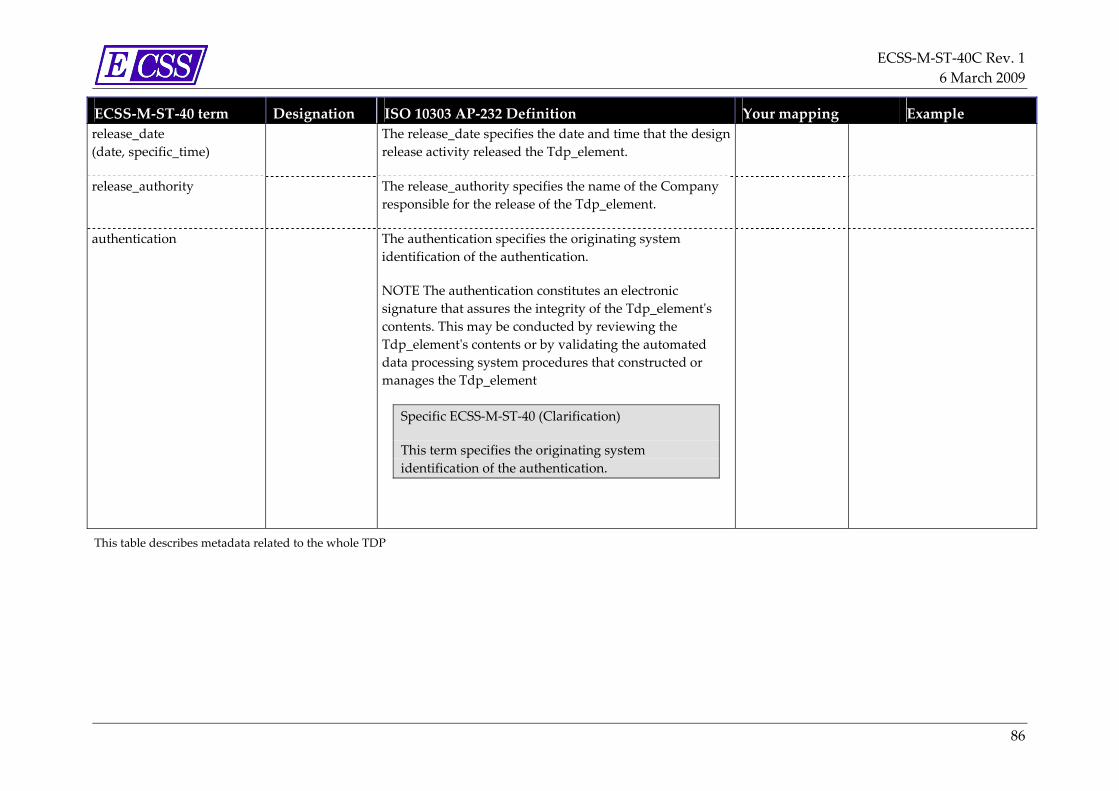
ECSS‐M‐ST‐40C Rev. 1 6 March 2009
86
ECSS‐M‐ST‐40 term Designation ISO 10303 AP‐232 Definition Your mapping Example release_date (date, specific_time)
The release_date specifies the date and time that the design release activity released the Tdp_element.
release_authority The release_authority specifies the name of the Company responsible for the release of the Tdp_element.
authentication The authentication specifies the originating system identification of the authentication.
NOTE The authentication constitutes an electronic signature that assures the integrity of the Tdp_elementʹs contents. This may be conducted by reviewing the Tdp_elementʹs contents or by validating the automated data processing system procedures that constructed or manages the Tdp_element
Specific ECSS‐M‐ST‐40 (Clarification)
This term specifies the originating system identification of the authentication.
This table describes metadata related to the whole TDP

ECSS‐M‐ST‐40C Rev. 1 6 March 2009
87
Table L‐3: item_properties
ECSS‐M‐ST‐40 term Designation ISO 10303 AP‐232 Definition Your mapping Example
/data_package/dde_definition_exchange/dde_body/item_properties/
* identifying_number * folder name The identifying_number specifies an Identifier or a Drawing_suffix_number_combination that is an identifier that defines the identification number for the Item as issued by the design_activity of the component.
Specific ECSS‐M‐ST‐40 (Replace ISO Definition)
The identifying_number specifies an Identifier that defines the identification number for the Item as issued by the design_activity of the component.
nomenclature_or_name folder label
The nomenclature_or_name specifies the name, noun phrase, or abbreviated name of the Item. The nomenclature_or_name need not be specified for a particular Item_identification.
This table describes metadata to build virtual folders within a TDP. Each item (=folder) can have many elements (=documents)

ECSS‐M‐ST‐40C Rev. 1 6 March 2009
88
Table L‐4: element
ECSS‐M‐ST‐40 term Designation ISO 10303 AP‐232 Definition Your mapping
Example
/data_package/dde_definition_exchange/dde_body/item_body/element/element_properties/
* identifying_number * Document reference The identifying_number specifies an identification number for the specific group of product information of interest as issued by the Design_activity.
NOTE The identifying_number may be an alphanumeric
ATV‐ST‐10‐029‐CN
* design_activity * Issuing company reference
The design_activities specifies the organization, company, business, or industry responsible for the Element_identification.
CNES
language_code Specifies the language use in the document.
The languages specifies the type of vocabulary nomenclatures used in the document or Tdp_element text. The langauges need not be specified for a particular Header. There may be more than one languages for a Header.
Specific ECSS‐M‐ST‐40 (Supplementary info)
ISO 639 2 letter code
http://www.w3.org/WAI/ER/IG/ert/iso639.htm
FR EN DE …

ECSS‐M‐ST‐40C Rev. 1 6 March 2009
89
ECSS‐M‐ST‐40 term Designation ISO 10303 AP‐232 Definition Your mapping
Example
/data_package/dde_definition_exchange/dde_body/item_body/element/element_properties/identification/document_element/
* title * Document title The title specifies the formal designation of the specific group of product information of interest. The title need not be specified for a particular Element_identification. .
Technical specification of solar array
* status_code * Life cycle or working process stage
The status_code specifies the process stage of the information.
NOTE Product Data Management (PDM) systems use this status to aid in identifying where in the life cycle an information element resides.
Unknown In Preparation In Review Released Withdrawn
* change_level * 1st level version level (issue)
The change_level specifies the latest alteration made to a File, Item, or Tdp_ element as part of a revision. The change_level need not be specified for a particular Change_identification.
NOTE For format standards, a change level may be the same as an addendum or amendment.
Specific ECSS‐M‐ST‐40 (Replace ISO Definition)
The change_level specifies the first level of version identification.
if version is 2.3 then the change_level is 2 and the issue_level is 3

ECSS‐M‐ST‐40C Rev. 1 6 March 2009
90
ECSS‐M‐ST‐40 term Designation ISO 10303 AP‐232 Definition Your mapping
Example
* date * specific_time
1st level version date (issue)
The change_date specifies either the date and time that the change_level was advanced or the date and time of the change. The change_date need not be specified for a particular Change_identification.
Specific ECSS‐M‐ST‐40 (Replace ISO Definition)
The change_date specifies either the date and time of the change.
date=2004‐11‐15 specific_time=23:59:59.99999+02:00
issue_level 2nd level version level (revision)
The issue_level specifies the issue number of the File, Item , or Tdp_element. The issue_level need not be specified for a particular Change_identification.
NOTE 1 Changes to documents are normally tracked by revisions and engineering change notices. However, in cases where changes to the document do not affect technical content, a new issue of the document may be provided for which no revision or engineering change notice level is advanced.
Specific ECSS‐M‐ST‐40 (Replace ISO Definition)
The issue_level specifies the second level of version identification.
if version is 2.3 then the change_level is 2 and the issue_level is 3

ECSS‐M‐ST‐40C Rev. 1 6 March 2009
91
ECSS‐M‐ST‐40 term Designation ISO 10303 AP‐232 Definition Your mapping
Example
date specific_time
2nd level version date (revision)
The issue_date specifies the date and time that the activity issued the File, Item, or Tdp_element. The issue_date need not be specified for a particular Change_identification.
Specific ECSS‐M‐ST‐40 (Replace ISO Definition)
The issue_date specifies either the date and time of the issue.
date=2004‐12‐20 specific_time=14:30:27
document_abstract list of abstracts (in several languages if needed)
The document_abstract specifies a brief overview of the document or Tdp_element. The document_abstract need not be specified for a particular Header.
authors (list) Specifies the list of authors for the document.
A Person is an individual with legal rights and duties. A person shall be uniquely identified for purposes of a data exchange.
Specific ECSS‐M‐ST‐40 (Supplementary info)
Note: Person and Person_and_organization ISO terms are replaced by person_and_company
A person shall exist in the <database> section of the XML Schema

ECSS‐M‐ST‐40C Rev. 1 6 March 2009
92
ECSS‐M‐ST‐40 term Designation ISO 10303 AP‐232 Definition Your mapping
Example
distribution_authorizations (list)
Specifies the distribution notice (allowed persons distribution)
The distribution_authorizations specifies the allowable circulation of information that is applicable to the Configuration. The distribution_authorizations need not be specified for a particular Configuration. There may be more than one distribution_authorizations for a Configuration.
Specific ECSS‐M‐ST‐40 (Replace ISO Definition)
The distribution_authorizations specifies the allowable circulation of information that is applicable to the Element. The distribution_authorizations need not be specified for a particular Element. There may be more than one distribution_authorizations for an Element.
element_code (list)
Type of document The element_code specifies the classification code for a Tdp_element.
NT CR PR …

ECSS‐M‐ST‐40C Rev. 1 6 March 2009
93
ECSS‐M‐ST‐40 term Designation ISO 10303 AP‐232 Definition Your mapping
Example
keyword (list)
Specifies the list of keywords in the document
The document_keywords specifies words that describe the main thought or topic of a document or Tdp_‐ element. The document_keywords need not be specified for a particular Header. There may be more than one keywords for a Header.
Specific ECSS‐M‐ST‐40 (Clarification)
The ISO term ʺdocument_keywordsʺ is renamed ʺkeywordsʺ in ECSS_M_ST_40 which is a list of ʺkeywordʺ
changes_managed_by_sender Specifies whether the element is configuration managed by the company issuying the TDP
Specific ECSS‐M‐ST‐40 (New) true or false
proprietary_extensions Proprietary extensions to document metadata
Specific ECSS‐M‐ST‐40 (New)
If two firms want to exchange some additional metadata, they can use this field to add some (key, value) metadata or to extend the XML Schema in order to exchange new metadata.
Note : These metadata are not exchangeable with companies that do not use the same proprietary_extensions.
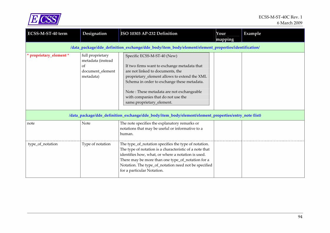
ECSS‐M‐ST‐40C Rev. 1 6 March 2009
94
ECSS‐M‐ST‐40 term Designation ISO 10303 AP‐232 Definition Your mapping
Example
/data_package/dde_definition_exchange/dde_body/item_body/element/element_properties/identification/
* proprietary_element * full proprietary metadata (instead of document_element metadata)
Specific ECSS‐M‐ST‐40 (New)
If two firms want to exchange metadata that are not linked to documents, the proprietary_element allows to extend the XML Schema in order to exchange these metadata.
Note : These metadata are not exchangeable with companies that do not use the same.proprietary_element.
/data_package/dde_definition_exchange/dde_body/item_body/element/element_properties/entry_note (list)
note Note The note specifies the explanatory remarks or notations that may be useful or informative to a human.
type_of_notation Type of notation The type_of_notation specifies the type of notation. The type of notation is a characteristic of a note that identifies how, what, or where a notation is used. There may be more than one type_of_notation for a Notation. The type_of_notation need not be specified for a particular Notation.

ECSS‐M‐ST‐40C Rev. 1 6 March 2009
95
ECSS‐M‐ST‐40 term Designation ISO 10303 AP‐232 Definition Your mapping
Example
/data_package/dde_definition_exchange/dde_body/item_body/element/element_body/entry_file (list)
* context_file_name * Element local file path within the Zip archive, relatively to the meta‐inf/datapackage.xml file
The context_file_name specifies the computer system file identification for the File.
NOTE When a file is being exchanged, the context_file_name is the fileʹs identification.
Specific ECSS‐M‐ST‐40 (Supplementary info)
.
In addition, the path is defined with characters \ . and ..
This field is an ʺImplementation fieldʺ that may be filled automatically by tools
../revue10/ ATV‐ST‐10‐029‐CN_02_05_[2].pdf
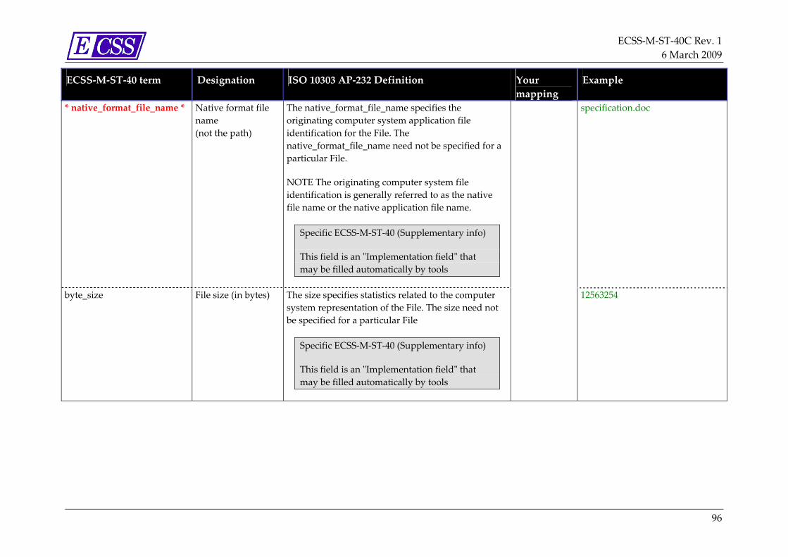
ECSS‐M‐ST‐40C Rev. 1 6 March 2009
96
ECSS‐M‐ST‐40 term Designation ISO 10303 AP‐232 Definition Your mapping
Example
* native_format_file_name * Native format file name (not the path)
The native_format_file_name specifies the originating computer system application file identification for the File. The native_format_file_name need not be specified for a particular File.
NOTE The originating computer system file identification is generally referred to as the native file name or the native application file name.
Specific ECSS‐M‐ST‐40 (Supplementary info)
This field is an ʺImplementation fieldʺ that may be filled automatically by tools
specification.doc
byte_size File size (in bytes) The size specifies statistics related to the computer system representation of the File. The size need not be specified for a particular File
Specific ECSS‐M‐ST‐40 (Supplementary info)
This field is an ʺImplementation fieldʺ that may be filled automatically by tools
12563254

ECSS‐M‐ST‐40C Rev. 1 6 March 2009
97
ECSS‐M‐ST‐40 term Designation ISO 10303 AP‐232 Definition Your mapping
Example
/data_package/dde_definition_exchange/dde_body/item_body/element/element_body/entry_url (list)
* url * url of a content Specific ECSS‐M‐ST‐40 (New)
In this case, the content file is not stored inside the datapackage, only the metadata are.
This field is an ʺImplementation fieldʺ that may be filled automatically by tools
http://www.ecss.nl/index.html
byte_size File size (in bytes) The size specifies statistics related to the computer system representation of the File. The size need not be specified for a particular File
Specific ECSS‐M‐ST‐40 (Supplementary info)
This field is an ʺImplementation fieldʺ that may be filled automatically by tools
12563254
This table describes metadata of a file

ECSS‐M‐ST‐40C Rev. 1 6 March 2009
98
Table L‐5: database
ECSS‐M‐ST‐40 term Designation ISO 10303 AP‐232 Definition Your mapping Example
/data_package/database/companies/company
* design_activity_code * Issuing company code
The design_activity_code specifies a company identifier code for the Design_authority responsible for the design content. The design_activity_code need not be specified for a particular Design_authority.
NOTE Many industry associations and governments assign unique design_activity_codes to each company.
ASTR
* name * Company name
The name specifies the textual label the company is known by ASTRIUM
address Companyʹs address
The address specifies the electronic or physical location where the company can be interfaced with. The address need not be specified for a particular Company.
/data_package/database/persons/person
* last_name *
first_name
middle_name
title
Email_address
This table describes persons and companies that are linked to elements

ECSS‐M‐ST‐40C Rev. 1 6 March 2009
99
Additional information on Table L‐1 to Table L‐5
Table L‐6 provides additional information to Table L‐1 to Table L‐5, by identifying all the ISO terms mentioned in column ʺISO 10303 AP‐232 Definitionʺ that are not defined in column ʺECSS‐M‐ST‐40 termʺ (note that these ISO terms correspond to intermediate nodes in the metadata model tree whose unique role is to gather sub terms without any other semantics).
In the following table, in front of each ISO term previously identified, an ECSS‐M‐ST‐40 term or a pointer to the Table L‐1 to Table L‐5 is given. For further details, see ecss_m_st_40.xsd.
Table L‐6: Additional information on Table L‐1 to Table L‐5
ISO 10303 AP 232 ECSS‐M‐ST‐40 Change change
change_date date attribute of Change element
Change_identification change_identification
Configuration configuration
Contract contract
data_definition_exchange data_definition_exchange
data_definition_exchange_header Table L‐2
Design_authority Company
document_keywords Keyword (list)
Element_identification element_identification
exchange_purpose dde_exchange_purpose
File File
Header replaced by document_elementType
Issue Issue
issue_date date attribute of Issue element
Item Table L‐3
item_classification item_classification
item_identification item_identification
Notation Notation
Person Person
Person_and_organization person_and_company
Product_model replaced by product_name
Security_classification security_classification
Tdp_element Table L‐4
ECSS‐M‐ST‐40C Rev. 1 6 March 2009
100
Annex M (informative) Digital signature
M.1 Introduction This annex provides information about the main principles and the implementation of the digital signature as approval method for information/documents.
M.2 Digital signature main principles The digital signature mechanism relies on an asymmetric cryptography.
Main digital signature components are:
• a public and private key
• an X.509 certificate
• a certificate authority
• a signature tool implementing “hash and cipher algorithm”
Digital signature relies on the following principles:
• Each signer has private and public keys (as for a credit card).
• The signer public key is linked to the signer through a certificate (X.509).
• The certificate is delivered by a certification authority which authenticates the signer and warrants the process for certificate delivery.
• The signer signs the document with his/her own and protected private key using a signature tool.
• The signed document contains signature(s) and information enabling the recipient to verify the signature(s).
• If needed, the recipient, trusting the certification authority of the signer, may verify signatures with the public key figuring in the signer certificate.

ECSS‐M‐ST‐40C Rev. 1 6 March 2009
101
Figure M‐1 Digital signature
M.3 Certificates
M.3.1 X.509 certificate X.509 certificates comply with the ISO/IEC/ITU‐T X.509 and IETF international standard.
An X.509 certificate is a collection of a standard set of fields containing information about a user or device and their corresponding public key. The X.509 standard defines what information goes into the certificate.
Additional detailed information can be taken from the following web site: http://www.ietf.org/rfc/rfc3280.txt.
M.3.2 Self-signed certificate A self‐signed certificate is a certificate auto‐generated by the signer. Some tools allow creation of such certificates. A self‐signed certificate is NOT delivered by a recognized certification authority that guarantees the signer identity. The trust level of a self‐signed certificate is extremely low.
M.4 Digital signature implementation There are several means and tools for digitally signing a document; hereafter is described a very simple implementation for signing PDF documents.
NOTE Using PDF format allows the digital signature and document to be embodied in a unique PDF document.

ECSS‐M‐ST‐40C Rev. 1 6 March 2009
102
M.4.1 Signature apposition Signature can be apposed after completion of the following steps;
a. Implement and retrieve an X509 signature certificate:
Certificate may be acquired closely certification authorities as for example:
⎯ VERISIGN (http://www.verisign.com),
⎯ THAWTE (http://www.thawte.com/),
⎯ Cacert (http://www.cacert.org/)
A certificate retrieval search can be performed using MICROSOFT Internet Explorer.
b. Find and install a signature tool like « Adobe Acrobat Standard, or UTIMACO».
These products enable to sign PDF with any X.509 certificates.
NOTE Adobe Acrobat Standard is different from “Adobe Acrobat Reader”. For more detailed information, go to http://www.adobe.com , or http://www.utimaco.com.
c. Import the certificate into “Signature Tool”.
d. Sign the PDF document using Signature Tool functions.
M.4.2 Signature verification A user who needs to verify the digital signature verifier has to install:
a. Adobe Acrobat Reader or equivalent depending on the signature tool
b. Certificates of certification authorities (in standard with VERISIGN and THAWTE).

ECSS‐M‐ST‐40C Rev. 1 6 March 2009
103
Bibliography
ECSS‐S‐ST‐00 ECSS system – Description, implementation and general requirements
ECSS‐E‐ST‐10 Space engineering – System engineering general requirements
ECSS‐E‐ST‐40 Space engineering – Software general requirements
ECSS‐Q‐ST‐20 Space product assurance – Quality assurance
ECSS‐Q‐ST‐80 Space product assurance – Software product assurance
ISO 10007:2003 Quality management – Guidelines for configuration management
ISO 10303 AP232 TDP definition
ISO/IEC TR 15846:1998
Information technology – Software life cycle processes ‐ Configuration management
ASME Y 14.100‐2000 Engineering drawing practices
ANSI/EIA‐649:2001 ANSI/EIA National Consensus Standard for configuration management