Embed Size (px)
Citation preview

www.nasa.gov
Space Launch System
Flight Control
Jeb S. Orr (Draper Laboratory)
NASA Marshall Space Flight Center
Control Systems Design and Analysis Branch (EV41)
Aerospace Control and Guidance Systems Committee
(ACGSC) Meeting 110
October 10-12, 2012
https://ntrs.nasa.gov/search.jsp?R=20130000629 2018-06-26T02:12:32+00:00Z
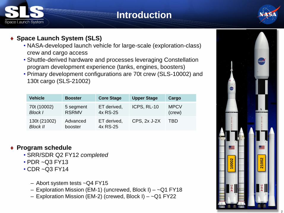
Space Launch System (SLS) • NASA-developed launch vehicle for large-scale (exploration-class)
crew and cargo access
• Shuttle-derived hardware and processes leveraging Constellation
program development experience (tanks, engines, boosters)
• Primary development configurations are 70t crew (SLS-10002) and
130t cargo (SLS-21002)
Program schedule • SRR/SDR Q2 FY12 completed
• PDR ~Q3 FY13
• CDR ~Q3 FY14
– Abort system tests ~Q4 FY15
– Exploration Mission (EM-1) (uncrewed, Block I) – ~Q1 FY18
– Exploration Mission (EM-2) (crewed, Block I) – ~Q1 FY22
Introduction
2
Vehicle Booster Core Stage Upper Stage Cargo
70t (10002)
Block I
5 segment
RSRMV
ET derived,
4x RS-25
ICPS, RL-10 MPCV
(crew)
130t (21002)
Block II
Advanced
booster
ET derived,
4x RS-25
CPS, 2x J-2X TBD
10002
21002

A new set of launch vehicle flight control design
challenges
• Large, highly flexible vehicle structure with non-planar
bending characteristics
• Complex TVC system with multiple fully actuated engines
• Massive propellant tanks with lightly damped lateral
sloshing modes
• Uncertain payload envelope with parasitic dynamics
(elastic, slosh)
• Highly optimized trajectories yielding widely varying
operating conditions
• Aggressive robustness and redundancy requirements
driven by human rating
SLS Flight Control Challenges
3
Flight Control System Overview
PID + linear bending filters is the architecture of choice
• Flight heritage, straightforward analysis, fundamentals understandable by non-controls
engineers
Decoupled-axis duplicate pitch/yaw designs do not generalize
• MOI, control effectiveness varies with respect to body axis
• Aerodynamic cross-coupling may be significant
Value added by augmenting PID/filters with a disturbance compensation algorithm
• Acceleration feedback (in some form) provides control over translational state of the
system, which may be desirable for several reasons (load relief, drift reduction, lateral
maneuvers, tower clearance)
• Generalization of classical load relief (acceleration feedback) control
• Includes a component that estimates bias angular accelerations
– Better performance can be obtained than with integral control alone with respect to
the same stability margin constraints
4 National Aeronautics and Space Administration
General Architecture Considerations
Use of multiple actuators necessitates an allocation algorithm
• Allocate actuator deflection to minimize some weighted figure of merit like total
deflection (steering losses, control authority) or actuator rate (capabilities)
• Can handle actuator failures based on external notification
Optimal allocation can be achieved with good accuracy based on combination of a
priori data and flight-critical measurements
• Multiple phases, throttled engines
– Control effectiveness is a function of time, propellant remaining, throttle, altitude, etc
• Transport delay and actuator dynamics are variable with allocation
– Special feature of TVC & flex dynamics: mixing affects stability and loads!
FCS design is more convenient in terms of angular acceleration than torque
– Eliminates some units and scaling issues in design of interacting parts
– Well-conditioned matrix manipulations for control allocation
5 National Aeronautics and Space Administration
Rely on simple, proven, flight-tested algorithms and processes • Classical PID control, gyro blending, linear bending filters, gain scheduling
• Extensive frequency-domain and time-domain robustness
• Algorithm and flight software commonality across all SLS platforms (common autopilot)
Enhance algorithm capability when warranted with compact and verifiable methods • On-line optimal linear control allocation
• High-performance acceleration based in-flight load relief capability
• Model reference gain adaptation with spectral feedback
Maximize robustness to failures • Tolerate at least one engine failure at any point in the flight regime with negligible impact to
flight control performance
• Demonstrate robustness to sensor failures and severe off-nominal conditions
Seamlessly integrate with the SLS Program to facilitate flight certification • Shift toward TPM (Technical Performance Metric) reporting rather than classical stability
margins and transient response characteristics only
• Opens the design space and burdens the flight control designer (rather than systems
engineering) with assessing the quality of the design at the lowest possible level
Flight Control Design Paradigms
6
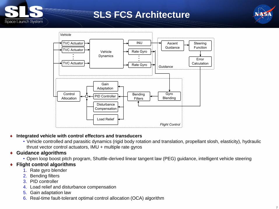
Integrated vehicle with control effectors and transducers
• Vehicle controlled and parasitic dynamics (rigid body rotation and translation, propellant slosh, elasticity), hydraulic
thrust vector control actuators, IMU + multiple rate gyros
Guidance algorithms • Open loop boost pitch program, Shuttle-derived linear tangent law (PEG) guidance, intelligent vehicle steering
Flight control algorithms 1. Rate gyro blender
2. Bending filters
3. PID controller
4. Load relief and disturbance compensation
5. Gain adaptation law
6. Real-time fault-tolerant optimal control allocation (OCA) algorithm
SLS FCS Architecture
7
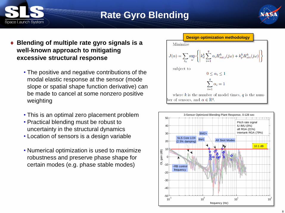
Blending of multiple rate gyro signals is a
well-known approach to mitigating
excessive structural response
• The positive and negative contributions of the
modal elastic response at the sensor (mode
slope or spatial shape function derivative) can
be made to cancel at some nonzero positive
weighting
• This is an optimal zero placement problem
• Practical blending must be robust to
uncertainty in the structural dynamics
• Location of sensors is a design variable
• Numerical optimization is used to maximize
robustness and preserve phase shape for
certain modes (e.g. phase stable modes)
Rate Gyro Blending
8
Design optimization methodology
10-1
100
101
102
-50
-40
-30
-20
-10
0
10
20
30
40
503-Sensor Optimized Blending Plant Response, 0-128 sec
frequency (Hz)
OL g
ain
(dB
)
BM2+
~RB control
frequency
SLS Core LOX
(2.5% damping)BM1 Aft Skirt Modes
Pitch rate signal
IU IMU (0%)
aft RGA (21%)
intertank RGA (79%)
10.1 dB

Sensor Trade Studies
9
1 2 3 4 5
IMU RGA
Various RGA locations considered to maximize robustness
Configuration 2 POD (Shuttle derived), configuration 3 baselined
Gain stable Marginally
gain
stabilized
Marginally
gain
stabilized
Gain stable Not easily
gain
stabilized
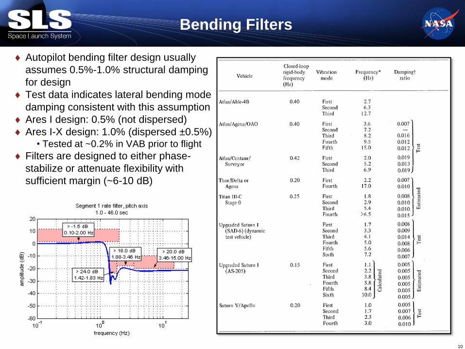
Autopilot bending filter design usually
assumes 0.5%-1.0% structural damping
for design
Test data indicates lateral bending mode
damping consistent with this assumption
Ares I design: 0.5% (not dispersed)
Ares I-X design: 1.0% (dispersed ±0.5%) • Tested at ~0.2% in VAB prior to flight
Filters are designed to either phase-
stabilize or attenuate flexibility with
sufficient margin (~6-10 dB)
Bending Filters
10
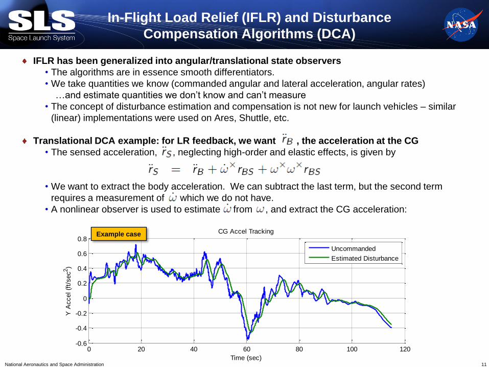
In-Flight Load Relief (IFLR) and Disturbance
Compensation Algorithms (DCA)
IFLR has been generalized into angular/translational state observers
• The algorithms are in essence smooth differentiators.
• We take quantities we know (commanded angular and lateral acceleration, angular rates)
…and estimate quantities we don’t know and can’t measure
• The concept of disturbance estimation and compensation is not new for launch vehicles – similar
(linear) implementations were used on Ares, Shuttle, etc.
Translational DCA example: for LR feedback, we want , the acceleration at the CG
• The sensed acceleration, , neglecting high-order and elastic effects, is given by
• We want to extract the body acceleration. We can subtract the last term, but the second term
requires a measurement of which we do not have.
• A nonlinear observer is used to estimate from , and extract the CG acceleration:
11 National Aeronautics and Space Administration
0 20 40 60 80 100 120-0.6
-0.4
-0.2
0
0.2
0.4
0.6
0.8CG Accel Tracking
Y A
ccel (f
t/sec
2)
Time (sec)
Uncommanded
Estimated Disturbance
0 20 40 60 80 100 120-0.4
-0.2
0
0.2
0.4CG Accel Tracking
Z A
ccel (f
t/sec2
)
Time (sec)
Uncommanded
Estimated Disturbance
Example case
12
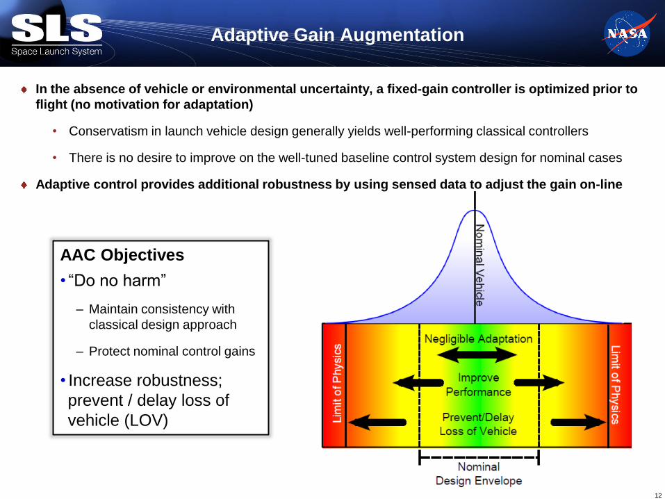
Adaptive Gain Augmentation
In the absence of vehicle or environmental uncertainty, a fixed-gain controller is optimized prior to
flight (no motivation for adaptation)
• Conservatism in launch vehicle design generally yields well-performing classical controllers
• There is no desire to improve on the well-tuned baseline control system design for nominal cases
Adaptive control provides additional robustness by using sensed data to adjust the gain on-line
AAC Objectives
• “Do no harm”
– Maintain consistency with
classical design approach
– Protect nominal control gains
• Increase robustness;
prevent / delay loss of
vehicle (LOV)

Current architecture has heritage to flight-tested systems
• MH-90 (F-101) and MH-96 (X-20, X-15), ca. 1958-1967
• Based on a prescribed servo limit cycle amplitude (marginal servo poles)
• Saw numerous flight tests (>60) on X-15-3, improved performance and pilot opinion of
handling qualities over wide-ranging flight envelope
• A similar concept is well-suited to a digital implementation
History
13

Launch vehicles are often conditionally stable due to competing objectives of unstable
aerodynamics and parasitic internal dynamics
Because of uncertainty in models, we have to design with sufficient gain margins
Adaptive gain augmentation senses off-nominal upper and lower limits in real time
Adaptive Gain Modulation
14
Flight Time
Lo
op
Gain
Upper Limit
(High Frequency/Flex & Servo Dynamics)
Lower Limit
(Performance, Aerodynamic Stability)

High-frequency closed-loop spectrum under high forward loop gain can be readily
deduced from the open-loop frequency response • Correlation allows design of spectral damper filters
• Used directly to determine high-pass cutoff frequency specification
Spectral Damper Concept
15
Nominal Open-Loop Response
Example Vehicle
Closed-Loop Response at Gimbal Command

Assume a well-tuned classical controller for the nominal system • The forward loop gain is augmented by a signal
– The total gain is formed from a fixed minimum gain and the augmenting gain;
• Multiplicative augmentation is easy to assess in terms of gain margin
• The update law for the augmenting signal depends on the command, sensed attitude and rate,
and the baseline controller output
Adaptive Augmenting Concept
16
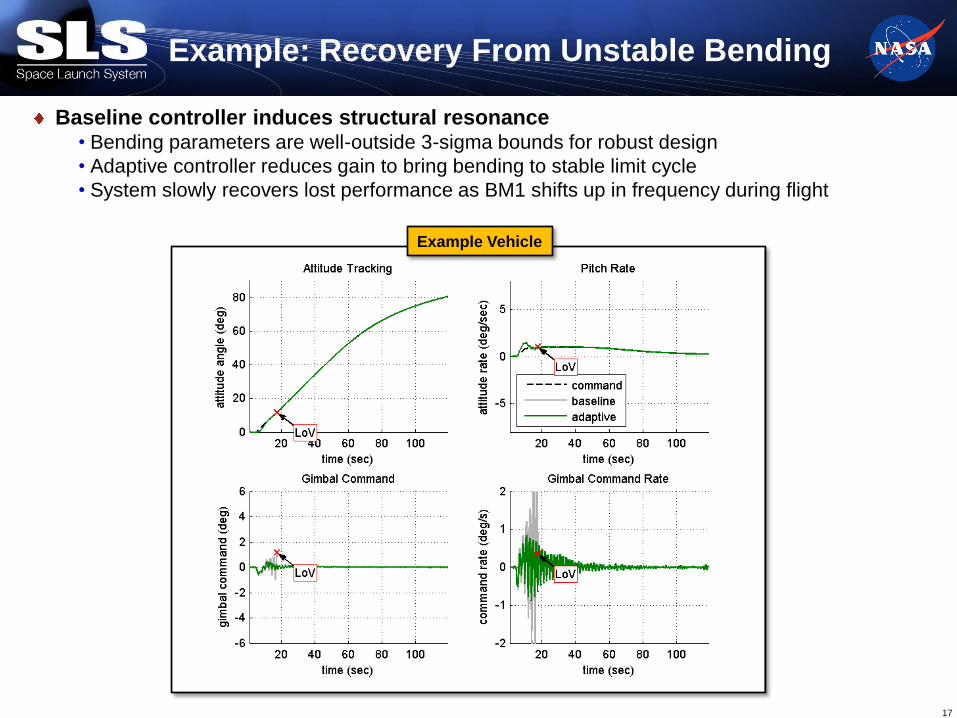
Baseline controller induces structural resonance • Bending parameters are well-outside 3-sigma bounds for robust design
• Adaptive controller reduces gain to bring bending to stable limit cycle
• System slowly recovers lost performance as BM1 shifts up in frequency during flight
Example: Recovery From Unstable Bending
17
Example Vehicle
Optimal Control Allocation
Multi-actuated thrust vector controlled systems are well-posed for control allocation
• Redundant control authority in three axes with two or more nozzles
• Some configurations may have nine or more nozzles, each with two degrees of freedom
Solutions to the constrained allocation problem exist and can be implemented online
• In the face of constraints, we must solve an LQ or LP using an iterative algorithm
• May not yield a moment collinear with command
• Other constrained solutions include daisy chaining, etc.
• A nonlinear solution: does not directly admit linear stability analysis
The constrained thrust vector control allocation problem differs from the aircraft problem
• Each control input has two degrees of freedom
• Saturation constraints are insufficient to represent the constraint boundary. Coupled constraints
apply to two degrees of freedom each
• Due to significant servoelastic coupling, the choice of effector mixing at a given flight condition
affects the stability of the closed-loop structural-dynamic system
• Linear allocators are preferred to enable linear stability analysis of the short period dynamics
for flight certification
• A linear allocator can be computed online based on optimal parameterization (e.g., a weighting
matrix)
18 National Aeronautics and Space Administration

Candidate Allocator Approaches
19 National Aeronautics and Space Administration
On-line Optimization
• LQ/LP
• Must consider convergence, stability analysis, computational expense
Generalized Inverse Matrix Lookup
• Interpolation of matrix do not give exact results
• Requires substantial data storage for sufficient resolution
Fixed polarity allocator with Vehicle/Engine Properties Scaling
• Shuttle-like approach
• Does not maximize the attainable moment
• Can adjust to guidance throttling
Fixed Allocator (Polarity Matrix)
• Gains contain engine & vehicle properties
• Does not maximize the attainable moment
• Steering loss & local thrust structure loads
Weighted Least Squares Cyclic Computation
• The best solution for launch vehicle application
• Reconfigurable In-flight to anomalies for which the system is prepared (engine out)
• Can adjust to guidance throttling
• Can maintain high allocation efficiency for many geometries
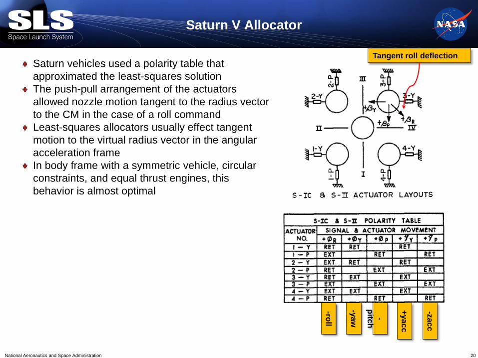
Saturn V Allocator
Saturn vehicles used a polarity table that
approximated the least-squares solution
The push-pull arrangement of the actuators
allowed nozzle motion tangent to the radius vector
to the CM in the case of a roll command
Least-squares allocators usually effect tangent
motion to the virtual radius vector in the angular
acceleration frame
In body frame with a symmetric vehicle, circular
constraints, and equal thrust engines, this
behavior is almost optimal
20 National Aeronautics and Space Administration
-roll
-ya
w
-
pitc
h
+ya
cc
-za
cc
Tangent roll deflection

WLS Control Allocator Formulation
We compute a moment effectiveness matrix as a function of time
In terms of angular acceleration, it becomes
We minimize
with
Yielding the standard (WLS) structured generalized inverse
• The weight matrix can be determined online based on knowledge
of the constraint boundaries and control effectiveness, such as
engine out and guidance throttling.
• The problem can be expressed in a coordinate system where the
matrix computations are sparse; scalar math can be used for high-
efficiency computation
• Constraints can be satisfied using special features of the
ellipsoidal topology of the constraint boundaries
21
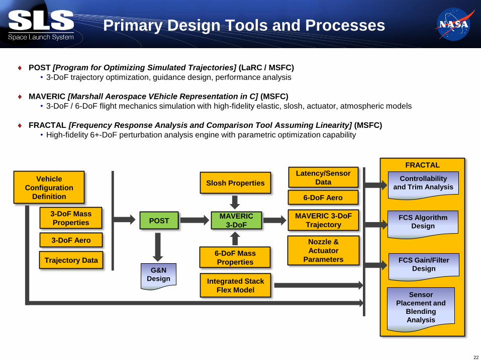
FRACTAL
Primary Design Tools and Processes
22
Vehicle
Configuration
Definition
3-DoF Mass
Properties
3-DoF Aero
Trajectory Data
POST
G&N
Design
MAVERIC
3-DoF
6-DoF Mass
Properties
Integrated Stack
Flex Model
MAVERIC 3-DoF
Trajectory
Slosh Properties
Nozzle &
Actuator
Parameters
Sensor
Placement and
Blending
Analysis
6-DoF Aero
Latency/Sensor
Data
FCS Algorithm
Design
FCS Gain/Filter
Design
POST [Program for Optimizing Simulated Trajectories] (LaRC / MSFC)
• 3-DoF trajectory optimization, guidance design, performance analysis
MAVERIC [Marshall Aerospace VEhicle Representation in C] (MSFC)
• 3-DoF / 6-DoF flight mechanics simulation with high-fidelity elastic, slosh, actuator, atmospheric models
FRACTAL [Frequency Response Analysis and Comparison Tool Assuming Linearity] (MSFC)
• High-fidelity 6+-DoF perturbation analysis engine with parametric optimization capability
Controllability
and Trim Analysis

CLVTOPS [TREETOPS-derived] (MSFC)
• Multiple flexible body dynamic simulation, separation analysis, liftoff clearance analysis
SAVANT [Stability Aerospace Vehicle ANalysis Tool] (MSFC)
• 6+-DoF Simulink®-based flight mechanics simulation supporting numerical linear stability analysis
FRACTAL [Frequency Response Analysis and Comparison Tool Assuming Linearity] (MSFC)
• Large scale Monte Carlo frequency domain analysis
Supporting Design Tools and Processes
FCS Algorithm
Design
FCS Gain/Filter
Design
MAVERIC
6-DoF
6-DoF Monte Carlo
Time Domain
CLVTOPS
SAVANT
External Analysis
(Loads, FSW)
FRACTAL
Liftoff/Separation
Analysis
6-DoF V&V,
Frequency Domain
Frequency Domain
Stability Analysis
Additional
Analysis
Products
6-DoF Aero
Integrated Stack
Flex Model
Guidance, MM
Design

NASA and contractor teammates have developed a robust, scalable architecture for
SLS flight control
A careful balance of modern and heritage design principles maximizes performance
and overall mission capability
Summary
24
MSFC EV41 SLS Flight Control Team
A. Alaniz
(Draper)
J. Bush
(TriVector)
J. Compton
(DCI)
S. Douglas
(MSFC)
S. Derry
(LaRC)
E. Gilligan
(MSFC)
C. E. Hall
(MSFC)
R. A. Hall
(CRM Solutions)
M. Hannan
(MSFC)
B. Hipp
(MSFC)
S. Hough
(DCI)
M. Johnson
(SAIC)
K. Black
(CRM Solutions)
J. Orr
(Draper)
J. Jang
(Draper)
J. Powers
(MSFC)
J. Pei
(LaRC)
T. VanZwieten
(MSFC)
J. Wall
(DCI)
J. Zhou
(LaRC)