Embed Size (px)
Citation preview
2012 SIMULIA Community Conference 1
Using Abaqus/Explicit to Link the Manufacturing Process to the Final Part Quality for Continuous
Fiber-Reinforced Composite Fabrics
Konstantine A. Fetfatsidis, Dimitri Soteropoulos, Alexander Petrov,
Cynthia J. Mitchell, and James A. Sherwood
Department of Mechanical Engineering, University of Massachusetts at Lowell, One University
Ave., Lowell, MA 01854, USA
Abstract: The manufacture of continuous fiber-reinforced composite parts often involves a design-
build-test methodology which can be expensive and time-consuming. A predictive design tool,
such as the finite element method, is valuable to assist in understanding the relationship between
the composite processing conditions and part quality, thus reducing the dependence on the design-
build-test methodology. The ability of the design tool to predict part quality based on
manufacturing process parameters is dependent upon the mechanical behavior of the fabric
reinforcements, which includes the in-plane shearing and tensile behaviors, bending stiffness and
friction between contacting surfaces during the manufacturing process. A hybrid finite element
discrete mesoscopic approach is proposed to model the forming of continuous fiber-reinforced
composite fabrics. The yarns are modeled by 1-D elements, and the shearing behavior of the
fabric is incorporated with 2-D elements. Forming simulations are demonstrated using an
automotive part and a wind turbine blade, where feedback can be provided to either change
processing parameters or part design to optimize part quality.
Keywords: Composites, Design Optimization, Fabrics, Finite Element, Thermostamping.
1. Introduction
The benefits of continuous fiber-reinforced polymer-matrix composites materials relative to metals
are well known, e.g. higher specific strength, higher specific stiffness, corrosion and fire-
resistance and tailored energy absorption. Multiple orientations of continuous, aligned fibers are
typically woven, knitted, or stitched (often referred to as non-crimp) together in a sheet of fabric. The aerospace, automotive, and wind-energy industries continue to increase their use of these
composite materials in an attempt to make lighter, more efficient parts. Processes such as Vacuum
Assisted Resin Transfer Molding (VARTM) (Aoki et al., 2010) and thermostamping (Gorczyca et
al., 2007)(Wakeman et al., 1998) are capable of producing lightweight quality parts relatively fast
with reasonably low processing costs. However, uncertainties in material behavior and in
processing conditions result in overdesigned parts that unnecessarily increase weight and costs.
Additionally, a time-consuming iterative design-build-test methodology is often used to determine
the most efficient design. The cost in time and labor is an obstacle to the widespread use of these
aligned-fiber fabric-reinforced composites.
A reliable simulation tool will help to explore the relationship between the processing conditions
and the forming of defects such as wrinkles or tearing while maintaining a cycle time that is as
2 2012 SIMULIA Community Conference
short as possible. In addition, the simulation tool can provide the positions and orientations of the
fabric constituents after forming which is of great importance for structural analysis of the formed
part. Such structural analyses could include modal analysis, stiffness and damage tolerance.
For a woven fabric and for many non-crimp fabrics, the main mode of deformation at the
mesoscopic scale (as opposed to the microscale, i.e. the scale of the fibers) is the in-plane shearing
of the fabric, which results in a change of the angle between the initially orthogonal yarns. In a
woven fabric, stretching of the fibers as a result of the uncrimping of the yarns is an additional
mode of deformation. After the yarns have “stretched” to their limit, then in-plane shearing is the
principal mode of deformation during the draping of a three-dimensional (3D) shape. The finite
element method is very amenable to the development of a simulation tool for continuous fiber-
reinforced fabric composites because it can account for the mechanical behavior of the fabric and
the complex boundary conditions (such as the effect of a binder). Geometrical methods such as
fishnet draping models do not have this ability and thus are only suitable to simulate handmade
draping (Boisse et al., 2008).
In the current work, a discrete approach based on an explicit finite element formulation using a
hypoelastic description is demonstrated for simulating the deformation of continuous fiber-
reinforced composite fabrics during forming processes. The explicit formulation was chosen
because it is the best suited formulation for forming simulations due to its computing time
efficiency and relatively robust contact algorithms. In developing this method, the objective was
to keep a relatively simple description and to have a scheme that can be implemented within
popular commercially available explicit finite element packages that allow for linking of user-
defined material subroutines with the explicit solver. To demonstrate this ability, the model was
implemented within the commercial explicit code, Abaqus/Explicit.
2. Model description
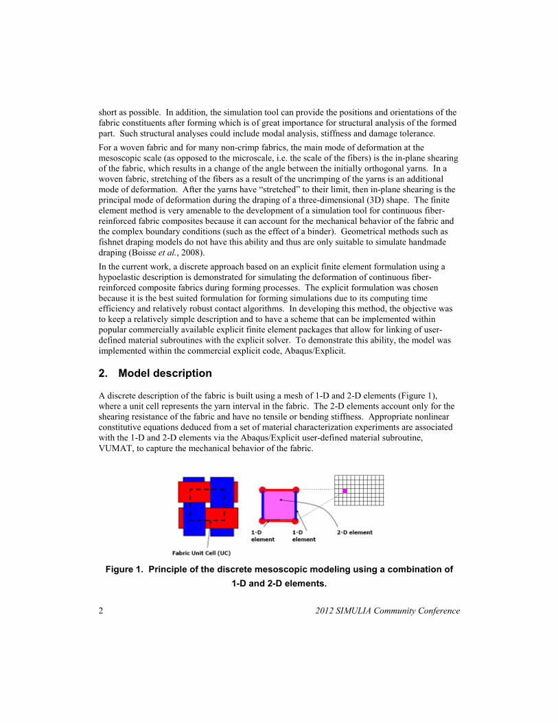
A discrete description of the fabric is built using a mesh of 1-D and 2-D elements (Figure 1),
where a unit cell represents the yarn interval in the fabric. The 2-D elements account only for the
shearing resistance of the fabric and have no tensile or bending stiffness. Appropriate nonlinear
constitutive equations deduced from a set of material characterization experiments are associated
with the 1-D and 2-D elements via the Abaqus/Explicit user-defined material subroutine,
VUMAT, to capture the mechanical behavior of the fabric.
Figure 1. Principle of the discrete mesoscopic modeling using a combination of
1-D and 2-D elements.
2012 SIMULIA Community Conference 3
Contact between layers of fabric and between the fabric and tooling is defined via the 2-D
elements. A constant coefficient of friction is traditionally assumed in forming simulations.
However, it has been shown that the polymer matrix in a composite fabric exhibits frictional
properties that vary as a function of several process parameters including pressure, velocity, and
matrix viscosity (Akkerman et al., 2007) (Chow, 2002) (Fetfatsidis, 2009) (Gamache, 2007)
(Gorczyca et al., 2003) (Vanclooster et al., 2008). As a result, it is necessary to use the
Abaqus/Explicit user-defined friction subroutine, VFRIC, to implement a variable friction
coefficient.
2.1 VUMAT: user-defined material subroutine
To model large deformation and strains, Abaqus/Explicit uses rate-dependent constitutive
equations, also called hypoelastic laws. Stresses are updated using the Hughes and Winget formula
(Bathe, 1996):
11 ++
∆+=t
ij
t
ij
t
ij σσσ (1)
21
1 .++
∆=∆t
klijkl
t
ij C εσ (2)
where 1+
∆t
ijσ is the stress increment at time step t+1, ijklC is the constitutive matrix and 2
1+∆
t
klε
is the midpoint strain increment obtained from the integration of the strain rate tensor.
Abaqus/Explicit allows the user to link custom constitutive models with the overall solver to
update the stress (Equation 2) via its user-defined material subroutine, VUMAT. The strain
increment, 21+
∆t
klε , is given by the solver to VUMAT that subsequently returns the corresponding
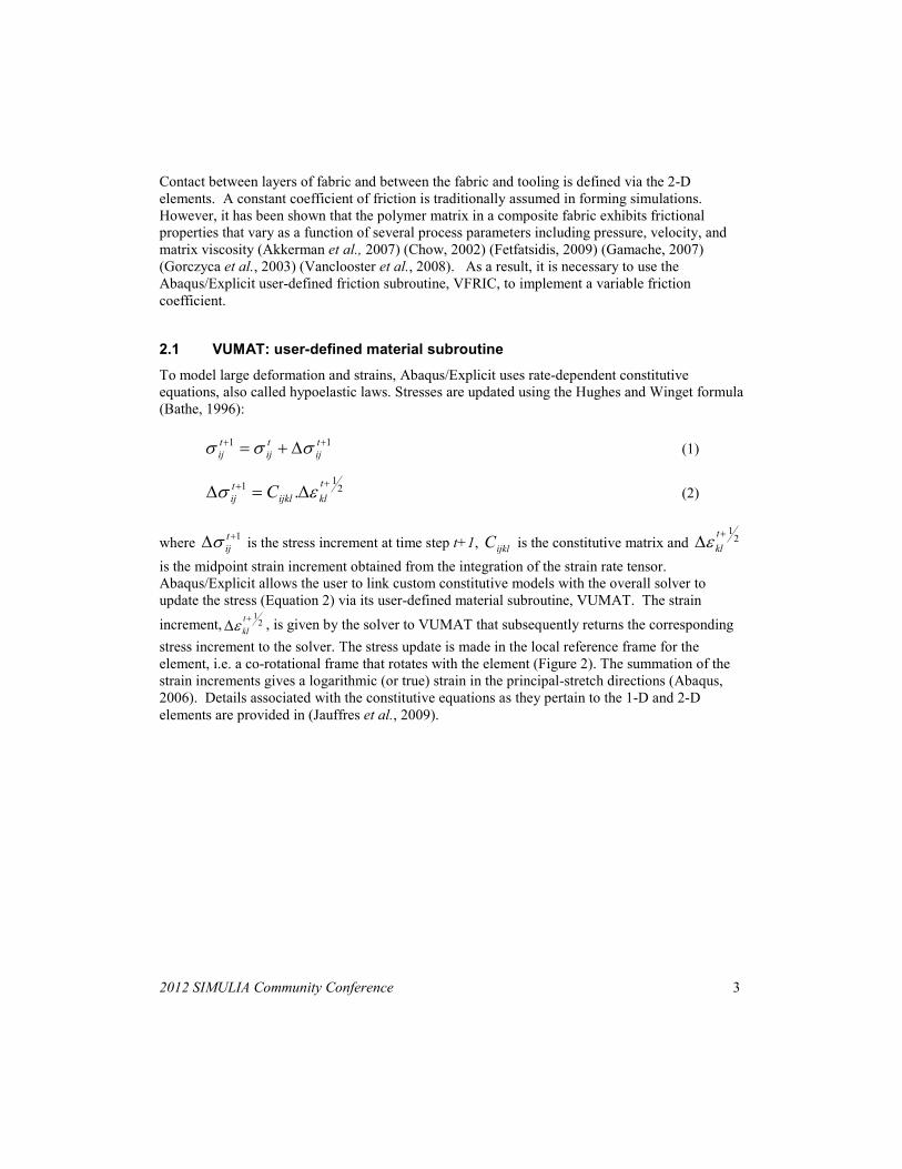
stress increment to the solver. The stress update is made in the local reference frame for the
element, i.e. a co-rotational frame that rotates with the element (Figure 2). The summation of the
strain increments gives a logarithmic (or true) strain in the principal-stretch directions (Abaqus,
2006). Details associated with the constitutive equations as they pertain to the 1-D and 2-D
elements are provided in (Jauffres et al., 2009).
4 2012 SIMULIA Community Conference
Figure 2. Schematic representation of the different coordinate systems used (Jauffres et al., 2009).
2.2 VFRIC: user-defined friction subroutine
The user-defined friction subroutine, VFRIC, in Abaqus/Explicit allows for the implementation of
a variable coefficient of friction between contact pairs. Nodes in contact are referred to as contact
points, and a local coordinate system is defined for each contact point to determine the frictional
forces and incremental slips (Abaqus, 2006).
During a forming simulation, the incremental frictional slip, or tangential motion during each time
increment for each contact point is passed to VFRIC from the Abaqus/Explicit solver. Similarly,
the magnitude of the normal force at each contact point is also passed to the subroutine at the end
of each time increment. The coefficient of friction is calculated as a function of the tangential
motion and the normal force within the subroutine and returned to the solver. The calculation of
the friction coefficient depends upon an experimental characterization of the frictional behavior
and the development of a phenomenological model that relates the nodal velocities and forces to
the coefficient of friction.
3. Material characterization and model validation
Several experiments must be performed to characterize the mechanical behavior of a continuous
fiber-reinforced fabric composite and to capture that behavior in the finite element model. These
experiments are outlined in (Sherwood et al., 2012). The basic fabric material characterization,
presented here, consists of quantifying the evolution of the shear stiffness as a function of yarn
rotation and the yarn tensile behavior. For prepreg fabrics, characterization is done over the range
of temperatures that can occur during fabric deformation. For dry fabrics, i.e. no prepreg, the
characterization can be done at room temperature.
2012 SIMULIA Community Conference 5
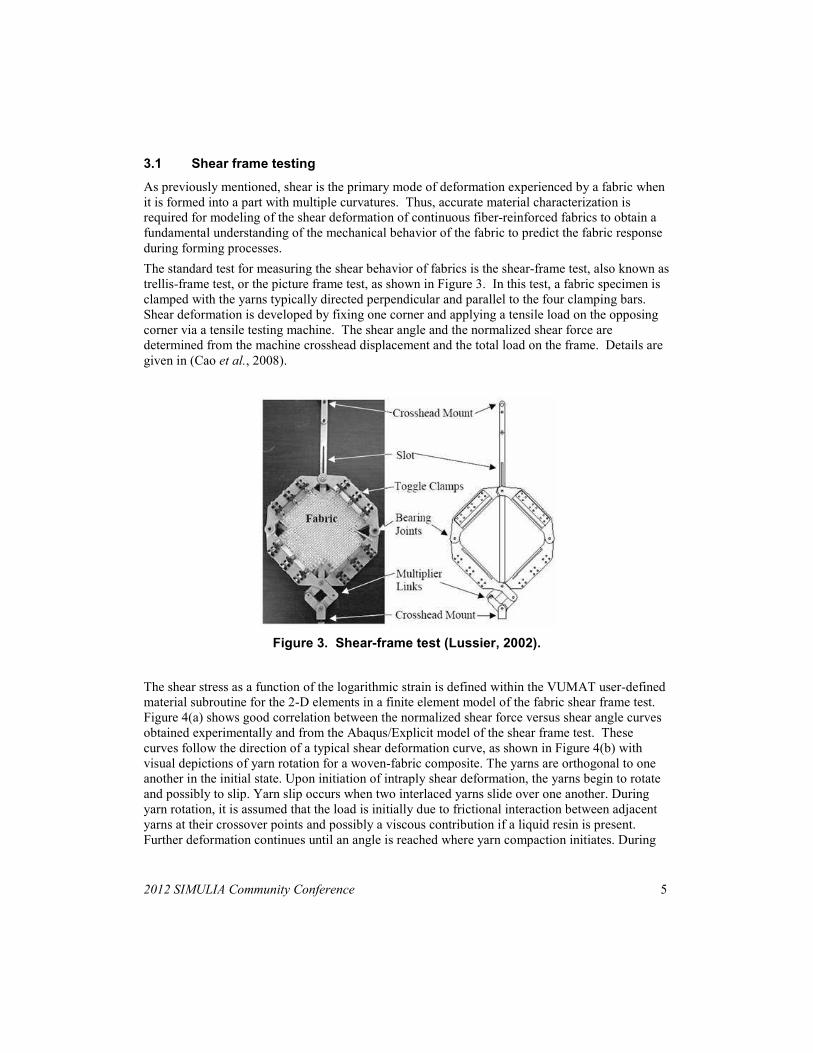
3.1 Shear frame testing
As previously mentioned, shear is the primary mode of deformation experienced by a fabric when
it is formed into a part with multiple curvatures. Thus, accurate material characterization is
required for modeling of the shear deformation of continuous fiber-reinforced fabrics to obtain a
fundamental understanding of the mechanical behavior of the fabric to predict the fabric response
during forming processes.
The standard test for measuring the shear behavior of fabrics is the shear-frame test, also known as
trellis-frame test, or the picture frame test, as shown in Figure 3. In this test, a fabric specimen is
clamped with the yarns typically directed perpendicular and parallel to the four clamping bars.
Shear deformation is developed by fixing one corner and applying a tensile load on the opposing
corner via a tensile testing machine. The shear angle and the normalized shear force are
determined from the machine crosshead displacement and the total load on the frame. Details are
given in (Cao et al., 2008).
Figure 3. Shear-frame test (Lussier, 2002).
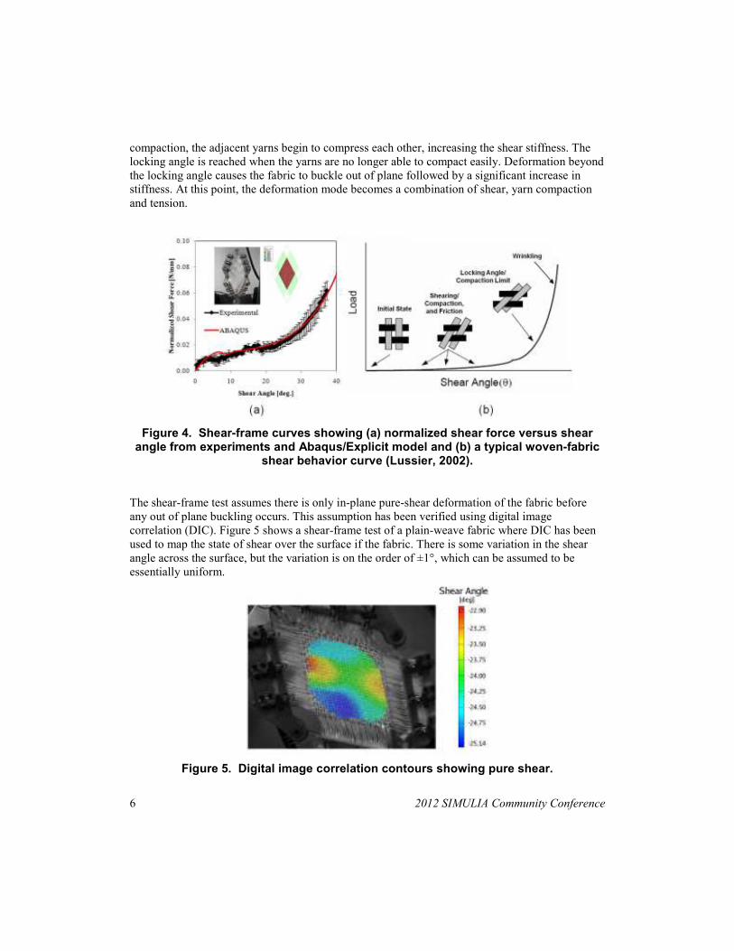
The shear stress as a function of the logarithmic strain is defined within the VUMAT user-defined
material subroutine for the 2-D elements in a finite element model of the fabric shear frame test.
Figure 4(a) shows good correlation between the normalized shear force versus shear angle curves
obtained experimentally and from the Abaqus/Explicit model of the shear frame test. These
curves follow the direction of a typical shear deformation curve, as shown in Figure 4(b) with
visual depictions of yarn rotation for a woven-fabric composite. The yarns are orthogonal to one
another in the initial state. Upon initiation of intraply shear deformation, the yarns begin to rotate
and possibly to slip. Yarn slip occurs when two interlaced yarns slide over one another. During
yarn rotation, it is assumed that the load is initially due to frictional interaction between adjacent
yarns at their crossover points and possibly a viscous contribution if a liquid resin is present.
Further deformation continues until an angle is reached where yarn compaction initiates. During
6 2012 SIMULIA Community Conference
compaction, the adjacent yarns begin to compress each other, increasing the shear stiffness. The
locking angle is reached when the yarns are no longer able to compact easily. Deformation beyond
the locking angle causes the fabric to buckle out of plane followed by a significant increase in
stiffness. At this point, the deformation mode becomes a combination of shear, yarn compaction
and tension.
Figure 4. Shear-frame curves showing (a) normalized shear force versus shear angle from experiments and Abaqus/Explicit model and (b) a typical woven-fabric
shear behavior curve (Lussier, 2002).
The shear-frame test assumes there is only in-plane pure-shear deformation of the fabric before
any out of plane buckling occurs. This assumption has been verified using digital image
correlation (DIC). Figure 5 shows a shear-frame test of a plain-weave fabric where DIC has been
used to map the state of shear over the surface if the fabric. There is some variation in the shear
angle across the surface, but the variation is on the order of ±1°, which can be assumed to be
essentially uniform.
Figure 5. Digital image correlation contours showing pure shear.
2012 SIMULIA Community Conference 7
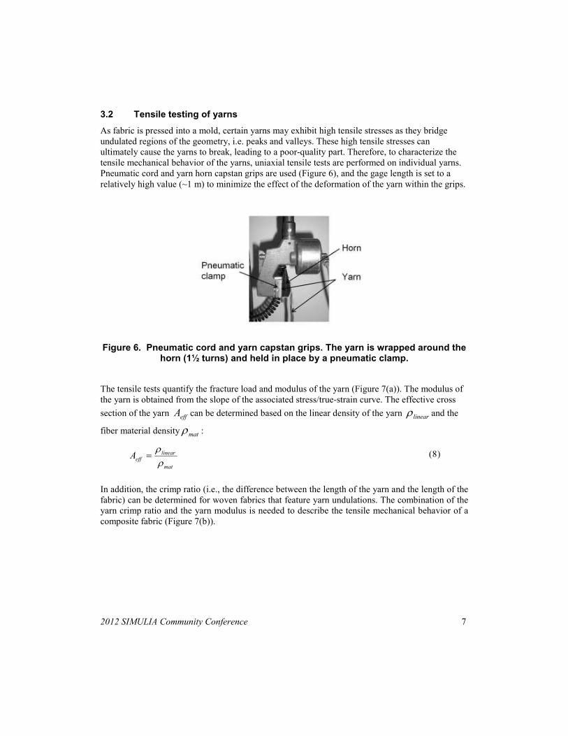
3.2 Tensile testing of yarns
As fabric is pressed into a mold, certain yarns may exhibit high tensile stresses as they bridge
undulated regions of the geometry, i.e. peaks and valleys. These high tensile stresses can
ultimately cause the yarns to break, leading to a poor-quality part. Therefore, to characterize the
tensile mechanical behavior of the yarns, uniaxial tensile tests are performed on individual yarns.
Pneumatic cord and yarn horn capstan grips are used (Figure 6), and the gage length is set to a
relatively high value (~1 m) to minimize the effect of the deformation of the yarn within the grips.
Figure 6. Pneumatic cord and yarn capstan grips. The yarn is wrapped around the horn (1½ turns) and held in place by a pneumatic clamp.
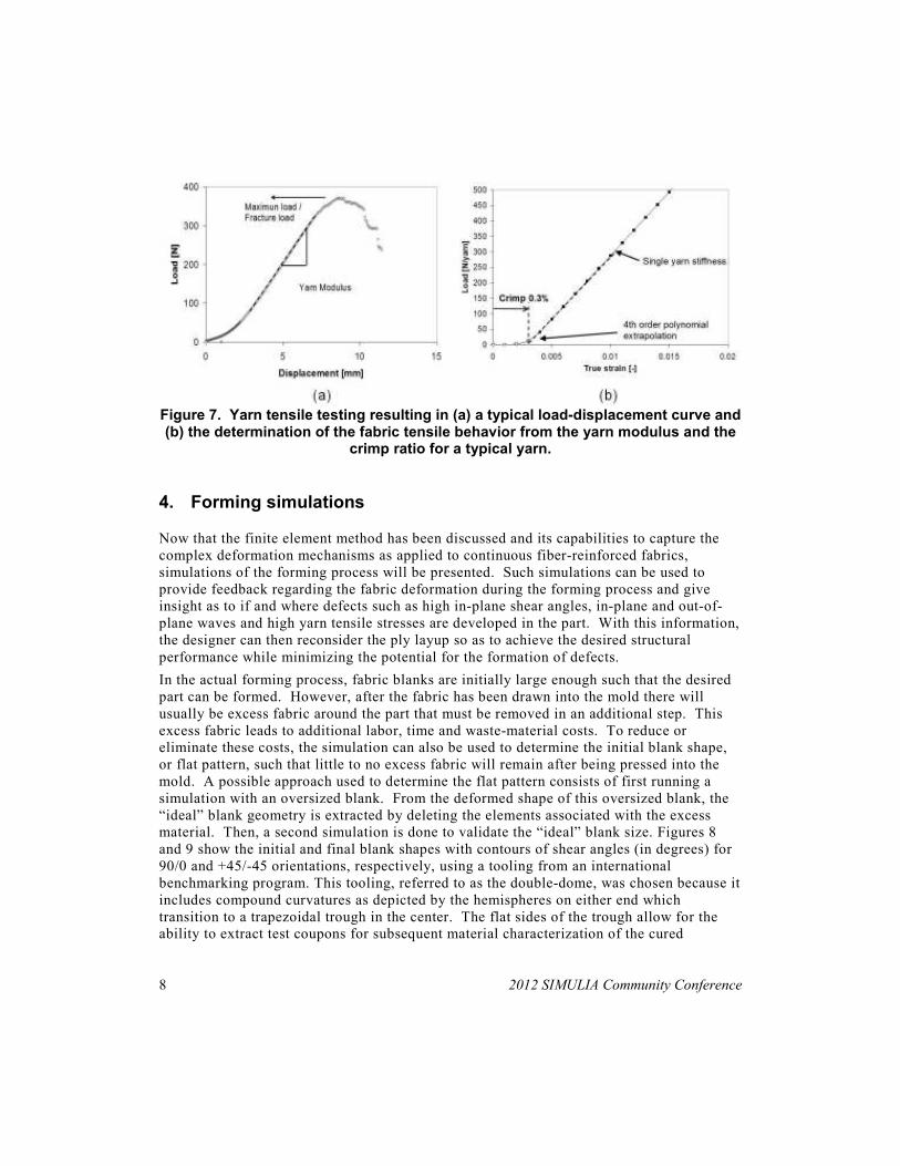
The tensile tests quantify the fracture load and modulus of the yarn (Figure 7(a)). The modulus of
the yarn is obtained from the slope of the associated stress/true-strain curve. The effective cross
section of the yarn effA can be determined based on the linear density of the yarn linearρ and the
fiber material density matρ :
mat
lineareffA
ρ
ρ= (8)
In addition, the crimp ratio (i.e., the difference between the length of the yarn and the length of the
fabric) can be determined for woven fabrics that feature yarn undulations. The combination of the
yarn crimp ratio and the yarn modulus is needed to describe the tensile mechanical behavior of a
composite fabric (Figure 7(b)).
8 2012 SIMULIA Community Conference
Figure 7. Yarn tensile testing resulting in (a) a typical load-displacement curve and (b) the determination of the fabric tensile behavior from the yarn modulus and the
crimp ratio for a typical yarn.
4. Forming simulations
Now that the finite element method has been discussed and its capabilities to capture the
complex deformation mechanisms as applied to continuous fiber-reinforced fabrics,
simulations of the forming process will be presented. Such simulations can be used to
provide feedback regarding the fabric deformation during the forming process and give
insight as to if and where defects such as high in-plane shear angles, in-plane and out-of-
plane waves and high yarn tensile stresses are developed in the part. With this information,
the designer can then reconsider the ply layup so as to achieve the desired structural
performance while minimizing the potential for the formation of defects.
In the actual forming process, fabric blanks are initially large enough such that the desired
part can be formed. However, after the fabric has been drawn into the mold there will
usually be excess fabric around the part that must be removed in an additional step. This
excess fabric leads to additional labor, time and waste-material costs. To reduce or
eliminate these costs, the simulation can also be used to determine the initial blank shape,
or flat pattern, such that little to no excess fabric will remain after being pressed into the
mold. A possible approach used to determine the flat pattern consists of first running a
simulation with an oversized blank. From the deformed shape of this oversized blank, the
“ideal” blank geometry is extracted by deleting the elements associated with the excess
material. Then, a second simulation is done to validate the “ideal” blank size. Figures 8
and 9 show the initial and final blank shapes with contours of shear angles (in degrees) for
90/0 and +45/-45 orientations, respectively, using a tooling from an international
benchmarking program. This tooling, referred to as the double-dome, was chosen because it
includes compound curvatures as depicted by the hemispheres on either end which
transition to a trapezoidal trough in the center. The flat sides of the trough allow for the
ability to extract test coupons for subsequent material characterization of the cured
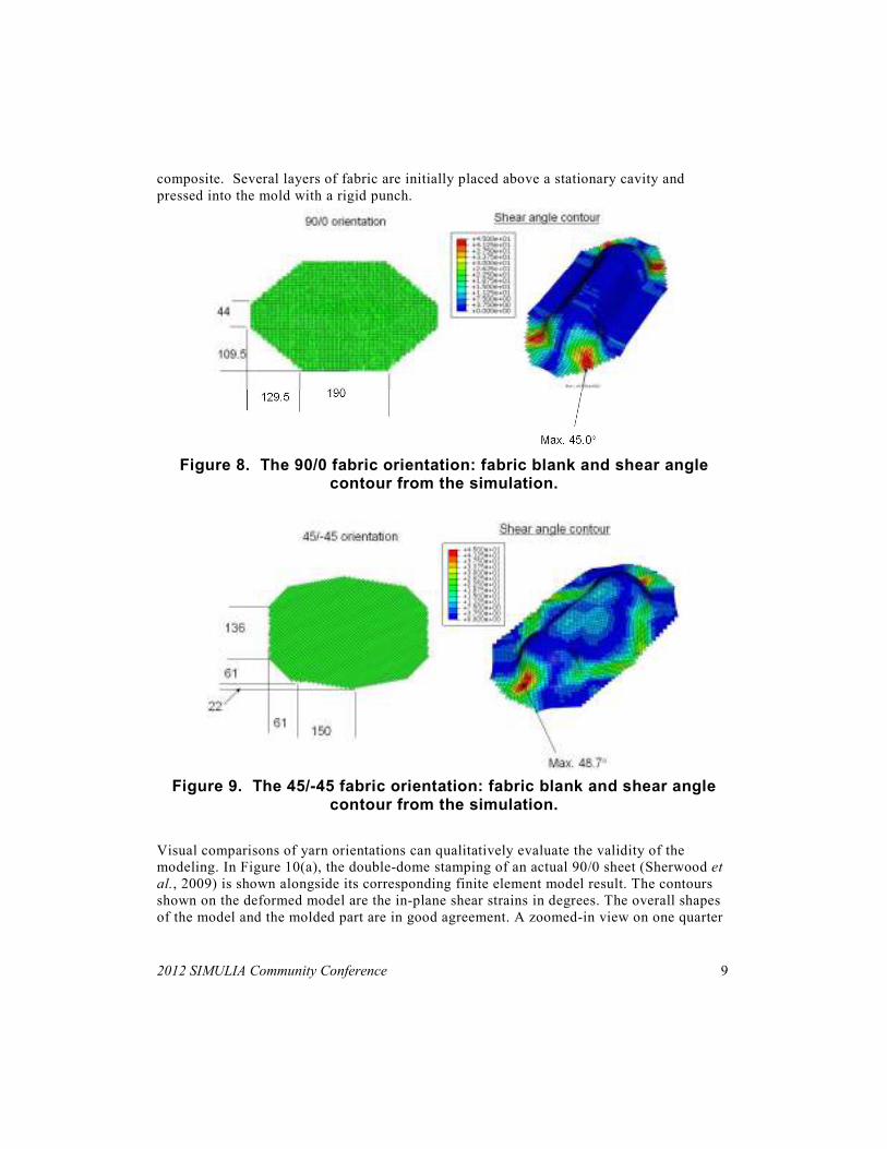
2012 SIMULIA Community Conference 9
composite. Several layers of fabric are initially placed above a stationary cavity and
pressed into the mold with a rigid punch.
Figure 8. The 90/0 fabric orientation: fabric blank and shear angle contour from the simulation.
Figure 9. The 45/-45 fabric orientation: fabric blank and shear angle contour from the simulation.
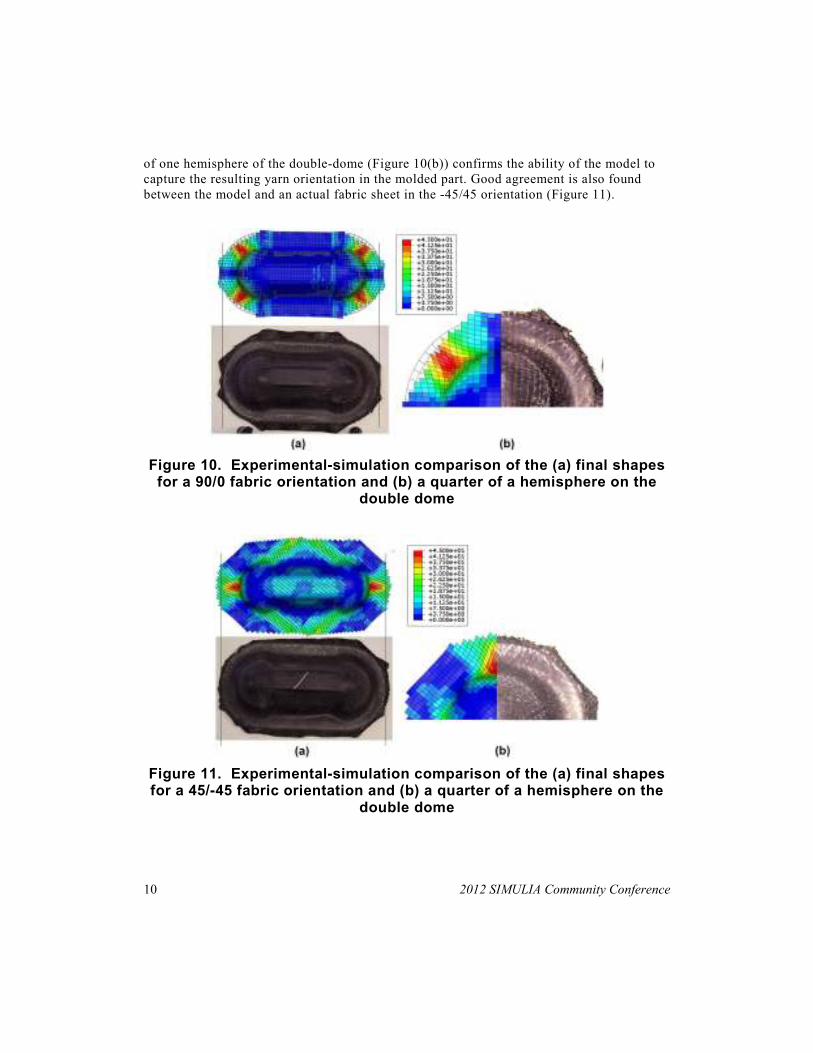
Visual comparisons of yarn orientations can qualitatively evaluate the validity of the
modeling. In Figure 10(a), the double-dome stamping of an actual 90/0 sheet (Sherwood et
al., 2009) is shown alongside its corresponding finite element model result. The contours
shown on the deformed model are the in-plane shear strains in degrees. The overall shapes
of the model and the molded part are in good agreement. A zoomed-in view on one quarter
10 2012 SIMULIA Community Conference
of one hemisphere of the double-dome (Figure 10(b)) confirms the ability of the model to
capture the resulting yarn orientation in the molded part. Good agreement is also found
between the model and an actual fabric sheet in the -45/45 orientation (Figure 11).
Figure 10. Experimental-simulation comparison of the (a) final shapes for a 90/0 fabric orientation and (b) a quarter of a hemisphere on the
double dome
Figure 11. Experimental-simulation comparison of the (a) final shapes for a 45/-45 fabric orientation and (b) a quarter of a hemisphere on the
double dome
2012 SIMULIA Community Conference
11
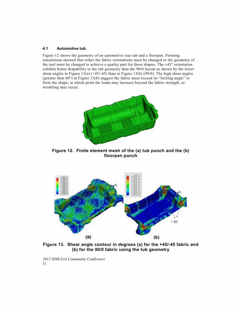
4.1 Automotive tub
Figure 12 shows the geometry of an automotive rear tub and a floorpan. Forming
simulations showed that either the fabric orientations must be changed or the geometry of
the tool must be changed to achieve a quality part for these shapes. The ±45° orientation
exhibits better drapability to the tub geometry than the 90/0 layout as shown by the lower
shear angles in Figure 13(a) (+45/-45) than in Figure 13(b) (90/0). The high shear angles
(greater than 60°) in Figure 13(b) suggest the fabric must exceed its “locking angle” to
form the shape, at which point the loads may increase beyond the fabric strength, or
wrinkling may occur.
Figure 12. Finite element mesh of the (a) tub punch and the (b) floorpan punch
Figure 13. Shear angle contour in degrees (a) for the +45/-45 fabric and (b) for the 90/0 fabric using the tub geometry
12 2012 SIMULIA Community Conference
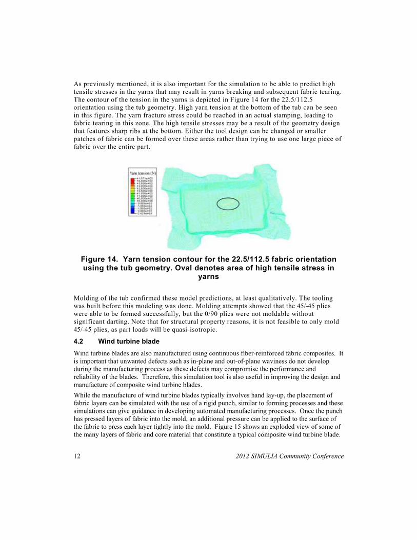
As previously mentioned, it is also important for the simulation to be able to predict high
tensile stresses in the yarns that may result in yarns breaking and subsequent fabric tearing.
The contour of the tension in the yarns is depicted in Figure 14 for the 22.5/112.5
orientation using the tub geometry. High yarn tension at the bottom of the tub can be seen
in this figure. The yarn fracture stress could be reached in an actual stamping, leading to
fabric tearing in this zone. The high tensile stresses may be a result of the geometry design
that features sharp ribs at the bottom. Either the tool design can be changed or smaller
patches of fabric can be formed over these areas rather than trying to use one large piece of
fabric over the entire part.
Figure 14. Yarn tension contour for the 22.5/112.5 fabric orientation using the tub geometry. Oval denotes area of high tensile stress in
yarns
Molding of the tub confirmed these model predictions, at least qualitatively. The tooling
was built before this modeling was done. Molding attempts showed that the 45/-45 plies
were able to be formed successfully, but the 0/90 plies were not moldable without
significant darting. Note that for structural property reasons, it is not feasible to only mold
45/-45 plies, as part loads will be quasi-isotropic.
4.2 Wind turbine blade
Wind turbine blades are also manufactured using continuous fiber-reinforced fabric composites. It
is important that unwanted defects such as in-plane and out-of-plane waviness do not develop
during the manufacturing process as these defects may compromise the performance and
reliability of the blades. Therefore, this simulation tool is also useful in improving the design and
manufacture of composite wind turbine blades.
While the manufacture of wind turbine blades typically involves hand lay-up, the placement of
fabric layers can be simulated with the use of a rigid punch, similar to forming processes and these
simulations can give guidance in developing automated manufacturing processes. Once the punch
has pressed layers of fabric into the mold, an additional pressure can be applied to the surface of
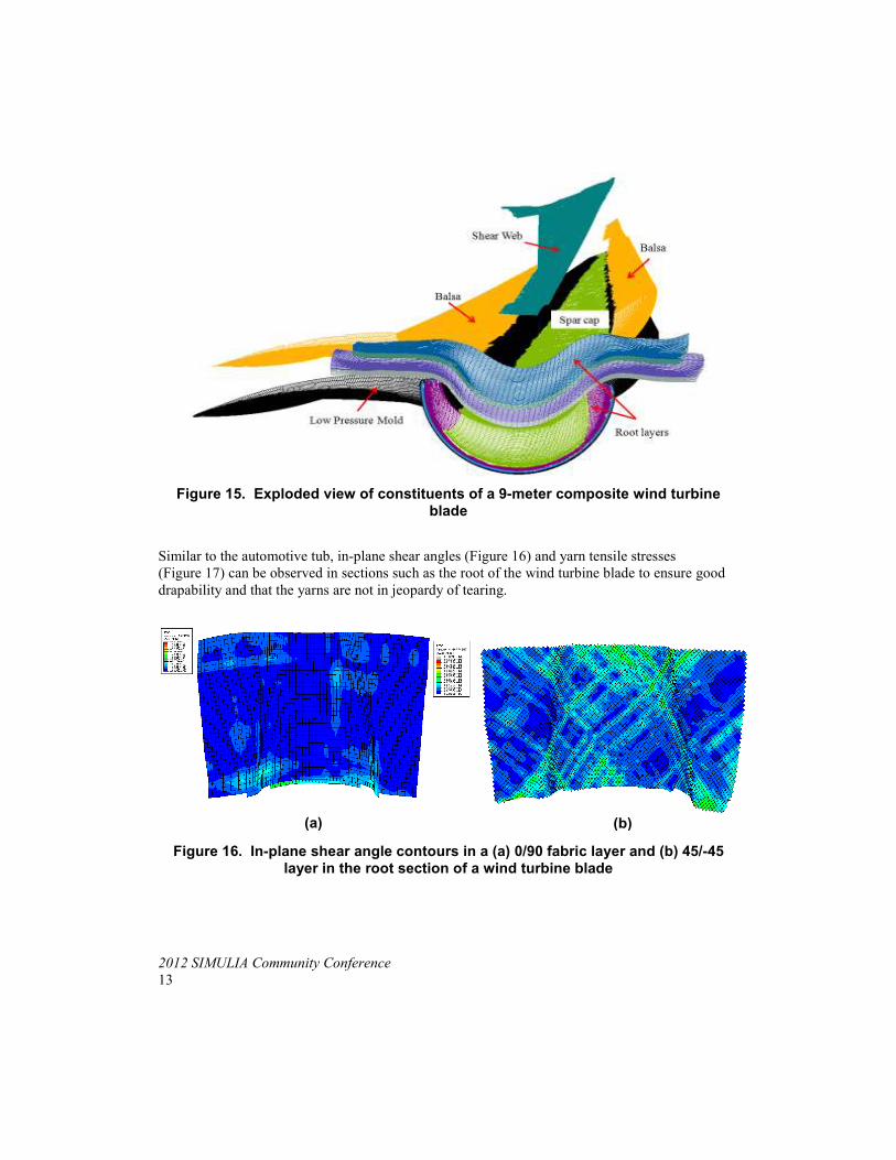
the fabric to press each layer tightly into the mold. Figure 15 shows an exploded view of some of
the many layers of fabric and core material that constitute a typical composite wind turbine blade.
2012 SIMULIA Community Conference
13
Figure 15. Exploded view of constituents of a 9-meter composite wind turbine blade
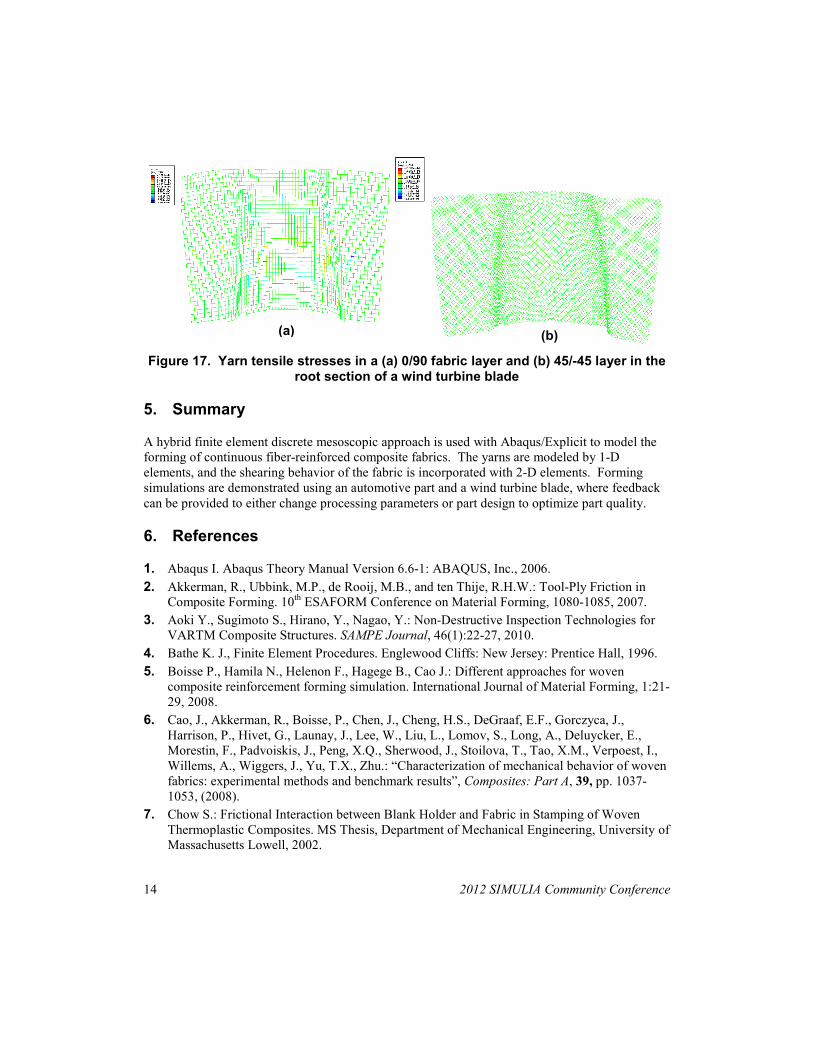
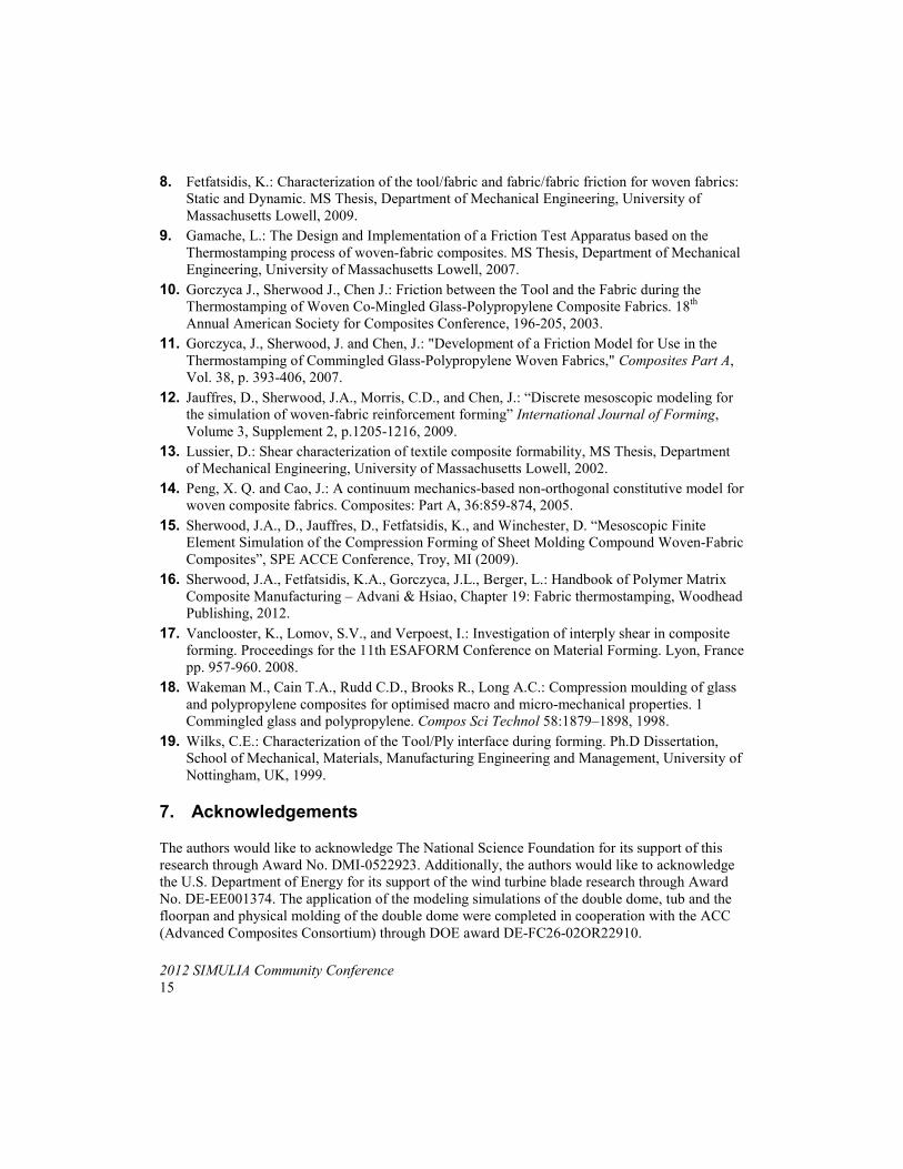
Similar to the automotive tub, in-plane shear angles (Figure 16) and yarn tensile stresses
(Figure 17) can be observed in sections such as the root of the wind turbine blade to ensure good
drapability and that the yarns are not in jeopardy of tearing.
Figure 16. In-plane shear angle contours in a (a) 0/90 fabric layer and (b) 45/-45 layer in the root section of a wind turbine blade
(a) (b)
14 2012 SIMULIA Community Conference
Figure 17. Yarn tensile stresses in a (a) 0/90 fabric layer and (b) 45/-45 layer in the root section of a wind turbine blade
5. Summary
A hybrid finite element discrete mesoscopic approach is used with Abaqus/Explicit to model the
forming of continuous fiber-reinforced composite fabrics. The yarns are modeled by 1-D
elements, and the shearing behavior of the fabric is incorporated with 2-D elements. Forming
simulations are demonstrated using an automotive part and a wind turbine blade, where feedback
can be provided to either change processing parameters or part design to optimize part quality.
6. References
1. Abaqus I. Abaqus Theory Manual Version 6.6-1: ABAQUS, Inc., 2006.
2. Akkerman, R., Ubbink, M.P., de Rooij, M.B., and ten Thije, R.H.W.: Tool-Ply Friction in
Composite Forming. 10th ESAFORM Conference on Material Forming, 1080-1085, 2007.
3. Aoki Y., Sugimoto S., Hirano, Y., Nagao, Y.: Non-Destructive Inspection Technologies for
VARTM Composite Structures. SAMPE Journal, 46(1):22-27, 2010.
4. Bathe K. J., Finite Element Procedures. Englewood Cliffs: New Jersey: Prentice Hall, 1996.
5. Boisse P., Hamila N., Helenon F., Hagege B., Cao J.: Different approaches for woven
composite reinforcement forming simulation. International Journal of Material Forming, 1:21-
29, 2008.
6. Cao, J., Akkerman, R., Boisse, P., Chen, J., Cheng, H.S., DeGraaf, E.F., Gorczyca, J.,
Harrison, P., Hivet, G., Launay, J., Lee, W., Liu, L., Lomov, S., Long, A., Deluycker, E.,
Morestin, F., Padvoiskis, J., Peng, X.Q., Sherwood, J., Stoilova, T., Tao, X.M., Verpoest, I.,
Willems, A., Wiggers, J., Yu, T.X., Zhu.: “Characterization of mechanical behavior of woven
fabrics: experimental methods and benchmark results”, Composites: Part A, 39, pp. 1037-
1053, (2008).
7. Chow S.: Frictional Interaction between Blank Holder and Fabric in Stamping of Woven
Thermoplastic Composites. MS Thesis, Department of Mechanical Engineering, University of
Massachusetts Lowell, 2002.
(a) (b)
2012 SIMULIA Community Conference
15
8. Fetfatsidis, K.: Characterization of the tool/fabric and fabric/fabric friction for woven fabrics:
Static and Dynamic. MS Thesis, Department of Mechanical Engineering, University of
Massachusetts Lowell, 2009.
9. Gamache, L.: The Design and Implementation of a Friction Test Apparatus based on the
Thermostamping process of woven-fabric composites. MS Thesis, Department of Mechanical
Engineering, University of Massachusetts Lowell, 2007.
10. Gorczyca J., Sherwood J., Chen J.: Friction between the Tool and the Fabric during the
Thermostamping of Woven Co-Mingled Glass-Polypropylene Composite Fabrics. 18th
Annual American Society for Composites Conference, 196-205, 2003.
11. Gorczyca, J., Sherwood, J. and Chen, J.: "Development of a Friction Model for Use in the
Thermostamping of Commingled Glass-Polypropylene Woven Fabrics," Composites Part A,
Vol. 38, p. 393-406, 2007.
12. Jauffres, D., Sherwood, J.A., Morris, C.D., and Chen, J.: “Discrete mesoscopic modeling for
the simulation of woven-fabric reinforcement forming” International Journal of Forming,
Volume 3, Supplement 2, p.1205-1216, 2009.
13. Lussier, D.: Shear characterization of textile composite formability, MS Thesis, Department
of Mechanical Engineering, University of Massachusetts Lowell, 2002.
14. Peng, X. Q. and Cao, J.: A continuum mechanics-based non-orthogonal constitutive model for
woven composite fabrics. Composites: Part A, 36:859-874, 2005.
15. Sherwood, J.A., D., Jauffres, D., Fetfatsidis, K., and Winchester, D. “Mesoscopic Finite
Element Simulation of the Compression Forming of Sheet Molding Compound Woven-Fabric
Composites”, SPE ACCE Conference, Troy, MI (2009).
16. Sherwood, J.A., Fetfatsidis, K.A., Gorczyca, J.L., Berger, L.: Handbook of Polymer Matrix
Composite Manufacturing – Advani & Hsiao, Chapter 19: Fabric thermostamping, Woodhead
Publishing, 2012.
17. Vanclooster, K., Lomov, S.V., and Verpoest, I.: Investigation of interply shear in composite
forming. Proceedings for the 11th ESAFORM Conference on Material Forming. Lyon, France
pp. 957-960. 2008.
18. Wakeman M., Cain T.A., Rudd C.D., Brooks R., Long A.C.: Compression moulding of glass
and polypropylene composites for optimised macro and micro-mechanical properties. 1
Commingled glass and polypropylene. Compos Sci Technol 58:1879–1898, 1998.
19. Wilks, C.E.: Characterization of the Tool/Ply interface during forming. Ph.D Dissertation,
School of Mechanical, Materials, Manufacturing Engineering and Management, University of
Nottingham, UK, 1999.
7. Acknowledgements
The authors would like to acknowledge The National Science Foundation for its support of this
research through Award No. DMI-0522923. Additionally, the authors would like to acknowledge
the U.S. Department of Energy for its support of the wind turbine blade research through Award
No. DE-EE001374. The application of the modeling simulations of the double dome, tub and the
floorpan and physical molding of the double dome were completed in cooperation with the ACC
(Advanced Composites Consortium) through DOE award DE-FC26-02OR22910.