Embed Size (px)
Citation preview

Tender Notice No : SOUTHCO/RGGVY/Line & Substation Materials/03 Page no. 1 of 99
SOUTHERN ELECTRICITY SUPPLY COMPANY OF ODISHA LTD.
CORPORATE OFFICE: COURTPETA–BERHAMPUR–760004
TENDER SPECIFICATION FOR PROCUREMENT OF DIFFERENT LINES
& SUBSTATION MATERIALS FOR RGGVY WORK
Tender Notification No.: SOUTHCO/RGGVY/Lines & Substation
Materials/ 03/2014-15 Dt. 13.08.2014
1. DATE OF OPENING OF TENDER: 02.09.2014
2. TIME: 3.30 PM
3. PLACE: Corporate Office, SOUTHCO
Courtpeta, Berhampur, Ganjam - 760004
SOUTHERN ELECTRICITY SUPPLY COMPANY OF ODISHA LTD.
Tender Notice No : SOUTHCO/RGGVY/Line & Substation Materials/03 Page no. 2 of 99
VOLUME- I
Tender Notification No.: SOUTHCO/RGGVY/Lines & Substation
Materials/ 03/2014-15 Dt. 13.08.2014
SSeeccttiioonn –– II
INVITATION FOR BIDS (IFB)

SOUTHERN ELECTRICITY SUPPLY COMPANY OF ODISHA LTD.
Tender Notice No : SOUTHCO/RGGVY/Line & Substation Materials/03 Page no. 3 of 99
1.0 The Southern Electricity Supply Company of Odisha ltd. (SOUTHCO) invites sealed tenders in
two part bidding system for supply of following items from the manufacturers of the said
materials only to SOUTHCO. The bidder must qualify in terms of the technical requirements as
specified in clause 5.0 stated below. The sealed envelopes shall be duly superscribed as
“TENDER NOTICE No: SOUTHCO/RGGVY/Line & Substation Material/ 03/2014-15 Dt. 13.08.2014
due for opening on dt. 02.09.2014” & the name of group for which bid is submitted.
Group Sl.
No. Item Description Unit Qty EMD
(Rs. in Lakhs)
PSC Poles
A 8 Mtr. Long 200 Kg. PSC Poles No. 6445
2.08 9 Mtr. Long 300 Kg. PSC Poles No. 2620
B
LT XLPE AB Cable
a 3x35 +1x 25 mm2 AB Cable Km. 266 2.13
C
AB Switch (Horizontal) & HG Fuse
a 11 KV, 200 Amp 3 Pole (H) AB Switch Set 504 0.81
b 11 KV, 400 Amp. 3 Pole HG Fuse Set 504
D
Lighting Arrestor
a 12 KV, 10 KA Lighting Arrestor No 1512 0.23
E
Insulators
a 11 KV Disc Insulator 70 KN (B & S type) No. 3413
0.18 b 11 KV Pin Insulator No. 4835
c LT Shackle Insulator No. 12374
F
Hardware Fittings for Disc Insulators
a 11 KV HW Fitting (B&S) Set 1707 0.06
G
G.I. Pin
a 11 KV GI Pin No. 4835 0.03
H
Cross Arm
a 11 KV “V” Cross Arm No. 1327 0.33
b LT 2 Ph. 3 wire Cross Arm No. 6445
I
Stay Set
a HT Stay Set (Complete) Set 1577 0.18
b LT Stay Set (complete) Set 1289
J
AAA Conductor
a 55 mm2 AAA Conductor Km. 295 0.88
K
Stay Wire
a 7/10 SWG GI Stay Wire MT 15.77 0.22
b 7/12 SWG GI Stay Wire MT 12.89
L LT GI Strap with Nuts & Bolts Pair 12374 0.06
M GI Earthing Coil for pole earth No 2901 0.05
N
Channel & Angle
a 100x50x6 mm MS Channel MT 66.57
0.92 b 75 x40x6 mm MS Channel MT 45.864
c 50x50x6 mm MS Angle MT 40.824
NB: In case of PSC Poles, the bidder must quote transportation charges extra in shape of Per MT/Per Km.

SOUTHERN ELECTRICITY SUPPLY COMPANY OF ODISHA LTD.
Tender Notice No : SOUTHCO/RGGVY/Line & Substation Materials/03 Page no. 4 of 99
2.0 The bidder is free to quote for any group of items or multiple groups. The bidder has to quote
for 100 % quantity of that group for which they submit their bid. The bidder has to submit
EMD in shape of A/c payee Bank Draft/Demand draft in favour of SOUTHCO Ltd. payable at
Berhampur as mentioned above against each group.
2.0 The schedule of specifications with detail terms & conditions can be obtained from address
given below against demand draft of Rs. 5,000/- plus 5% VAT, drawn in favour of SOUTHCO
Ltd., payable at Berhampur. The tender papers will be issued on all working days up-to
01.09.2014.
The tender documents can also be downloaded from the website
“www.southcoodisha.com”.
In case tender papers are downloaded from the above website, then the bidder has to
enclose a demand draft covering the cost of bid documents as stated above in a separate
envelope with suitable superscription “Cost of Bid Documents : Tender Notice No. :
SOUTHCO/RGGVY/Line & Substation Material/ 03/2014-15 Dt. 13.08.2014”. This envelope should
accompany the Bid Documents.
3.0 Offers will be received up-to 1.00 PM. on dt. 02.09.2014 as indicated earlier and will be
opened at the address given below at 3.30 PM. on same day in presence of the authorized
representatives of the bidders. The schedule of specifications with detail terms & conditions
are enclosed. It is the sole responsibility of the bidder to ensure that the bid documents reach
this office on or before the cut off due date of tender opening.
4.0 SOUTHCO reserves the right to accept / reject any or all Bidders without assigning any reason
thereof and alter the quantity of materials mentioned in the Tender documents at the time of
placing purchase orders. Bids will be summarily rejected if:
(i). EMD is not deposited in shape of Bank Draft in favor of SOUTHCO Ltd., payable at
Berhampur. Bid security (EMD) against previous Tenders, if any, will not be adjusted
towards Bid security (EMD) against this Tender.
(ii). The offer does not contain “FOR, Berhampur price indicating break-up towards all
taxes & duties”.
(iii). Complete Technical details are not enclose
(iv). Tender is received after due date & time due to any reason.
SOUTHERN ELECTRICITY SUPPLY COMPANY OF ODISHA LTD.
Tender Notice No : SOUTHCO/RGGVY/Line & Substation Materials/03 Page no. 5 of 99
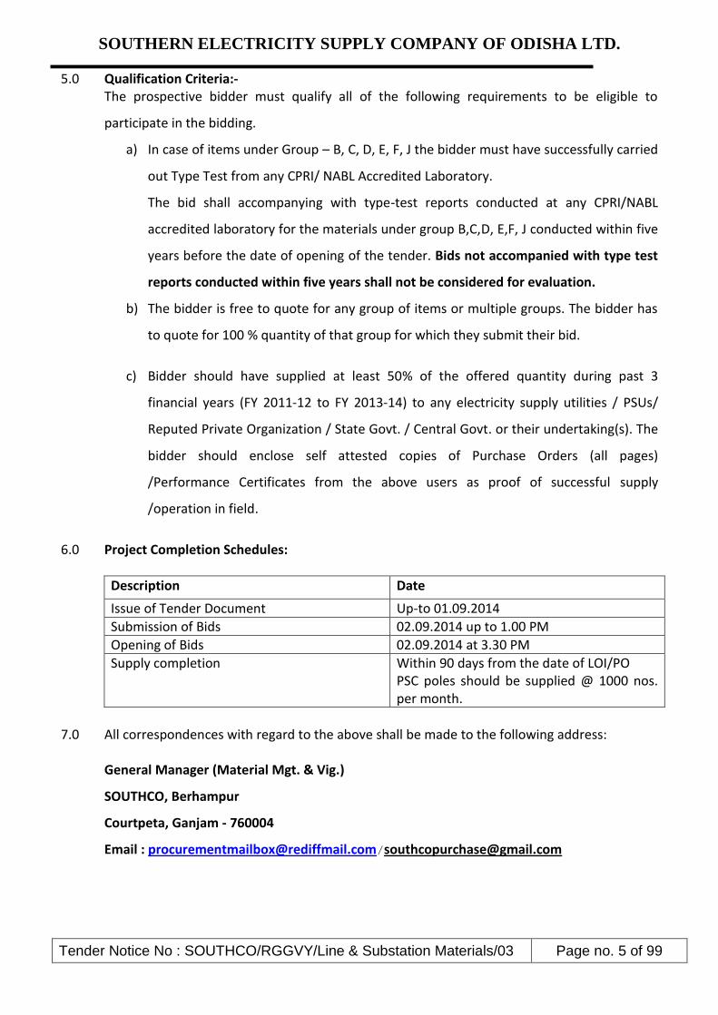
5.0 Qualification Criteria:- The prospective bidder must qualify all of the following requirements to be eligible to
participate in the bidding.
a) In case of items under Group – B, C, D, E, F, J the bidder must have successfully carried
out Type Test from any CPRI/ NABL Accredited Laboratory.
The bid shall accompanying with type-test reports conducted at any CPRI/NABL
accredited laboratory for the materials under group B,C,D, E,F, J conducted within five
years before the date of opening of the tender. Bids not accompanied with type test
reports conducted within five years shall not be considered for evaluation.
b) The bidder is free to quote for any group of items or multiple groups. The bidder has
to quote for 100 % quantity of that group for which they submit their bid.
c) Bidder should have supplied at least 50% of the offered quantity during past 3
financial years (FY 2011-12 to FY 2013-14) to any electricity supply utilities / PSUs/
Reputed Private Organization / State Govt. / Central Govt. or their undertaking(s). The
bidder should enclose self attested copies of Purchase Orders (all pages)
/Performance Certificates from the above users as proof of successful supply
/operation in field.
6.0 Project Completion Schedules:
Description Date
Issue of Tender Document Up-to 01.09.2014
Submission of Bids 02.09.2014 up to 1.00 PM
Opening of Bids 02.09.2014 at 3.30 PM
Supply completion Within 90 days from the date of LOI/PO PSC poles should be supplied @ 1000 nos. per month.
7.0 All correspondences with regard to the above shall be made to the following address:
General Manager (Material Mgt. & Vig.)
SOUTHCO, Berhampur
Courtpeta, Ganjam - 760004
Email : [email protected]/[email protected]

SOUTHERN ELECTRICITY SUPPLY COMPANY OF ODISHA LTD.
Tender Notice No : SOUTHCO/RGGVY/Line & Substation Materials/03 Page no. 6 of 99
SSEECCTTIIOONN –– IIII
INSTRUCTION TO BIDDERS (ITB)
Tender Notification No.: SOUTHCO/RGGVY/Line & Substation
Material/ 03/2014-15 Dt. 13.08.2014

SOUTHERN ELECTRICITY SUPPLY COMPANY OF ODISHA LTD.
Tender Notice No : SOUTHCO/RGGVY/Line & Substation Materials/03 Page no. 7 of 99
A. GENERAL 1.0 Southern Electricity Supply Company of Odisha Ltd. (SOUTHCO), hereinafter referred to as the
“Purchaser” is desirous of implementing the various works at their licensed area in the state of Odisha under RGGVY Scheme (11th Plan). The Purchaser has now floated this tender for procurement of various items as notified earlier in this bid document.
2.0 SCOPE OF WORK
The scope shall include Design, Manufacture, Shop Testing at works conforming to the Technical Specifications enclosed herewith along with Packing, Forwarding, Freight and Insurance and Unloading and proper stacking at Purchaser’s stores.
3.0 DISCLAIMER 3.01 This Document includes statements, which reflect various assumptions, which may or may
not be correct. Each Bidder/Bidding Consortium should conduct its own estimation and analysis and should check the accuracy, reliability and completeness of the information in this Document and obtain independent advice from appropriate sources in their own interest.
3.02 Neither Purchaser nor its employees will have any liability whatsoever to any Bidder or any
other person under the law or contract, the principles of restitution or unjust enrichment or otherwise for any loss, expense or damage whatsoever which may arise from or be incurred or suffered in connection with anything contained in this Document, any matter deemed to form part of this Document, provision of Services and any other information supplied by or on behalf of Purchaser or its employees, or otherwise arising in any way from the selection process for the Supply.
3.03 Though adequate care has been taken while issuing the Bid document, the Bidder should
satisfy itself that documents are complete in all respects. Intimation of any discrepancy shall be given to this office immediately.
3.04 This Document and the information contained herein are Strictly Confidential and are for the use of only the person(s) to whom it is issued. It may not be copied or distributed by the recipient to third parties (other than in confidence to the recipient’s professional advisors).
4.0 COST OF BIDDING The Bidder shall bear all costs associated with the preparation and submission of its Bid and
Purchaser will in no case be responsible or liable for those costs. B. BIDDING DOCUMENTS 5.0 BIDDING DOCUMENTS 5.01 The Scope of Work, Bidding Procedures and Contract Terms are described in the Bidding
Documents. In addition to the covering letter accompanying Bidding Documents, the Bidding Documents include:
SOUTHERN ELECTRICITY SUPPLY COMPANY OF ODISHA LTD.
Tender Notice No : SOUTHCO/RGGVY/Line & Substation Materials/03 Page no. 8 of 99
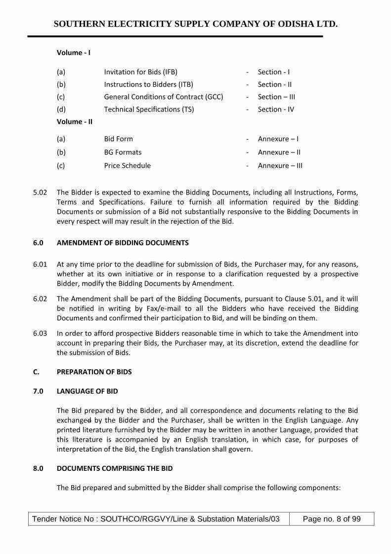
Volume - I (a) Invitation for Bids (IFB) - Section - I
(b) Instructions to Bidders (ITB) - Section - II
(c) General Conditions of Contract (GCC) - Section – III
(d) Technical Specifications (TS) - Section - IV
Volume - II
(a) Bid Form - Annexure – I
(b) BG Formats - Annexure – II
(c) Price Schedule - Annexure – III
5.02 The Bidder is expected to examine the Bidding Documents, including all Instructions, Forms, Terms and Specifications. Failure to furnish all information required by the Bidding Documents or submission of a Bid not substantially responsive to the Bidding Documents in every respect will may result in the rejection of the Bid.
6.0 AMENDMENT OF BIDDING DOCUMENTS
6.01 At any time prior to the deadline for submission of Bids, the Purchaser may, for any reasons, whether at its own initiative or in response to a clarification requested by a prospective Bidder, modify the Bidding Documents by Amendment.
6.02 The Amendment shall be part of the Bidding Documents, pursuant to Clause 5.01, and it will be notified in writing by Fax/e-mail to all the Bidders who have received the Bidding Documents and confirmed their participation to Bid, and will be binding on them.
6.03 In order to afford prospective Bidders reasonable time in which to take the Amendment into account in preparing their Bids, the Purchaser may, at its discretion, extend the deadline for the submission of Bids.
C. PREPARATION OF BIDS 7.0 LANGUAGE OF BID The Bid prepared by the Bidder, and all correspondence and documents relating to the Bid
exchanged by the Bidder and the Purchaser, shall be written in the English Language. Any printed literature furnished by the Bidder may be written in another Language, provided that this literature is accompanied by an English translation, in which case, for purposes of interpretation of the Bid, the English translation shall govern.
8.0 DOCUMENTS COMPRISING THE BID The Bid prepared and submitted by the Bidder shall comprise the following components:

SOUTHERN ELECTRICITY SUPPLY COMPANY OF ODISHA LTD.
Tender Notice No : SOUTHCO/RGGVY/Line & Substation Materials/03 Page no. 9 of 99
(a) Bid Form, Price & other Schedules (STRICTLY AS PER FORMAT) and Technical Data Sheets completed in accordance with Clause 9.0, 10.0, 11.0 and Technical Specification;
(b) All the Bids must be accompanied with the required bid security (EMD) as mentioned in
the Section-I of this tender. (c) Power of Attorney indicating that the person(s) signing the Bid have the authority to sign
the Bid and thus that the Bid is binding upon the Bidder during the full period of its validity, in accordance with clause 12.0.
9.0 BID FORM 9.01 The Bidder shall complete an ‘Original’ and another one ‘Copy’ of the Bid Form and the
appropriate Price & Other Schedules and Technical Data Sheets furnished in the Volume-II of the Bidding Documents.
9.02 Bid Security/Earnest Money Deposit (EMD)
Pursuant to Clause 8.0 (b) above, the bidder shall furnish, as part of its bid, bid security (EMD) as indicated in the Section-I in shape of Bank draft/Demand Draft in favour of SOUTHCO Ltd. payable at Berhampur. The bid security is required to protect the Purchaser against the risk of Bidder’s conduct which would warrant the security’s forfeiture. Unsuccessful bidders’ bid security will be discharged or returned as promptly as possible but not later than thirty (30) days after the expiration of the period of bid validity. The successful bidder’s bid security will be discharged upon furnishing the Composite performance Bank Guarantee. The bid security may be forfeited: (a) if the Bidder:
i) Withdraws its bid during the period of bid validity specified in the tender.
(b) in the case of a successful Bidder, if the Bidder fails:
(i) to accept the order within the stipulated period mentioned in the order, or (ii) to furnish the required Composite performance Bank Guarantee within the stipulated
period.
10.0 BID PRICES
10.01 Bidders shall quote for the entire Scope of Supply with a break-up of prices for individual items. The total Bid Price shall also cover all the Supplier's obligations mentioned in or reasonably to be inferred from the Bidding Documents in respect of Design, Supply, Transportation to site, all in accordance with the requirement of Bidding Documents. The Bidder shall complete the appropriate Price Schedules included herein, stating the Unit Price for each item & total Price.

SOUTHERN ELECTRICITY SUPPLY COMPANY OF ODISHA LTD.
Tender Notice No : SOUTHCO/RGGVY/Line & Substation Materials/03 Page no. 10 of 99
10.02 The prices offered shall be inclusive of all costs as well as Duties, Taxes and Levies paid or
payable during execution of the supply work, break up of price constituents, should be there. 10.03 Prices quoted by the Bidder shall be “Firm” and not subject to any price adjustment during
the performance of the Contract. A Bid submitted with an adjustable price quotation will be treated as non-responsive and rejected.
10.04 Price schedule for each group/material should be submitted in separate envelops mentioning the Name of material & Group.
11.0 BID CURRENCIES Prices shall be quoted in Indian Rupees Only. 12.0 PERIOD OF VALIDITY OF BIDS
12.01 Bids shall remain valid for 180 days from the date of opening of the Bid. 12.02 Notwithstanding Clause 12.01 above, the Purchaser may solicit the Bidder’s consent to an
extension of the Period of Bid Validity. The request and the responses thereto shall be made in writing by Fax/e-mail.
13.0 ALTERNATIVE BIDS Bidders shall submit Bids, which comply with the Bidding Documents. Alternative Bids will
not be considered. 14.0 FORMAT AND SIGNING OF BID 14.01 The original Bid Form and accompanying documents (as specified in Clause 9.0), clearly
marked "Original Bid", plus one copy must be received by the Purchaser at the date, time and place specified pursuant to Clauses 15.0 and 16.0. In the event of any discrepancy between the original and the copies, the original shall govern.
14.02 The original and copy of the Bid shall be typed or written in indelible ink and shall be signed
by the Bidder or a person or persons duly authorized to sign on behalf of the Bidder. Such authorization shall be indicated by written Power-of-Attorney accompanying the Bid.
14.03 The Bid shall contain no interlineations, erasures or overwriting except as necessary to correct errors made by the Bidder, in which case such corrections shall be initialed by the person or persons signing the Bid.
D. SUBMISSION OF BIDS
15.0 SEALING AND MARKING OF BIDS
15.01 Bid submission: One original & one Copy (hard copies) of all the Bid Documents shall be sealed and submitted to the Purchaser before the closing time for submission of the bid.

SOUTHERN ELECTRICITY SUPPLY COMPANY OF ODISHA LTD.
Tender Notice No : SOUTHCO/RGGVY/Line & Substation Materials/03 Page no. 11 of 99
15.02 The Technical Documents and the Bid Security shall be enclosed in a sealed envelope and the
said envelope shall be superscribed with “Technical & Bid Security”. The price bids of each group shall be inside another sealed envelope with superscription “Price Bid”. Both these envelopes shall be sealed inside another big envelope. All the envelopes should bear the Name and Address of the Bidder and marking for the Original and Copy. The envelopes should be super-scribed with “Tender Notice No. & Due date of opening & Name of Group for which bid is submitted”.
15.03 The Bidder has the option of sending the Bids in person. Bids submitted by
Telex/Telegram/Fax will not be accepted. No request from any Bidder to the Purchaser to collect the proposals from Airlines/Cargo Agents etc shall be entertained by the Purchaser.
16.0 DEADLINE FOR SUBMISSION OF BIDS 16.01 The original Bid, together with the required copies, must be received by the Purchaser at the
address specified no later than 1.00 PM. on 02.09.2014. 16.02 The Purchaser may, at its discretion, extend the deadline for the submission of Bids by
amending the Bidding Documents in accordance with Clause 9.0, in which case all rights and obligations of the Purchaser and Bidders previously subject to the deadline will thereafter be subject to the deadline as extended.
17.0 ONE BID PER BIDDER Each Bidder shall submit only one Bid. A Bidder who submits more than one Bid for the same
material will cause all those Bids to be rejected.
18.0 LATE BIDS Any Bid received by the Purchaser after the deadline for submission of Bids prescribed by the
Purchaser, pursuant to Clause 16.0, will be declared "Late" and rejected and returned unopened to the Bidder.
19.0 MODIFICATIONS AND WITHDRAWAL OF BIDS 19.01 The Bidder is not allowed to modify or withdraw its Bid after the Bid’s submission & during
the validity period of the bid. If any bidder withdraw his bid during validity period of the tender as per clause no. 12 above, his Bid Security (EMD) shall be forfeited.
E EVALUATION OF BID
20.0 PROCESS TO BE CONFIDENTIAL Information relating to the examination, clarification, evaluation and comparison of Bids and
recommendations for the award of a contract shall not be disclosed to Bidders or any other persons not officially concerned with such process. Any effort by a Bidder to influence the

SOUTHERN ELECTRICITY SUPPLY COMPANY OF ODISHA LTD.
Tender Notice No : SOUTHCO/RGGVY/Line & Substation Materials/03 Page no. 12 of 99
Purchaser's processing of Bids or award decisions may result in the rejection of the Bidder's Bid.
21.0 CLARIFICATION OF BIDS To assist in the examination, evaluation and comparison of Bids, the Purchaser may, at its
discretion, ask the Bidder for a clarification of its Bid. All responses to requests for clarification shall be in writing and no change in the price or substance of the Bid shall be sought, offered or permitted.
22.0 PRELIMINARY EXAMINATION OF BIDS / RESPONSIVENESS 22.01 Purchaser will examine the Bids to determine whether they are complete, whether any
computational errors have been made, whether required sureties have been furnished, whether the documents have been properly signed, and whether the Bids are generally in order.
22.02 Arithmetical errors will be rectified on the following basis. If there is a discrepancy between
the unit price (landing Cost) and the total price per item that is obtained by multiplying the unit price (landing Cost) and quantity, the unit price (landing Cost) shall prevail and the total price per item will be corrected. If there is a discrepancy between the Total Amount and the sum of the total price per item, the sum of the total price per item shall prevail and the Total Amount will be corrected.
22.03 Prior to the detailed evaluation, Purchaser will determine the substantial responsiveness of
each Bid to the Bidding Documents including production capability and acceptable quality of the Goods offered. A substantially responsive Bid is one, which conforms to all the terms and conditions of the Bidding Documents without material deviation.
22.04 A Bid determined as not substantially responsive will be rejected by the Purchaser and / or
the Purchaser and may not subsequently be made responsive by the Bidder by correction of the non-conformity.
23.0 EVALUATION AND COMPARISON OF BIDS 23.01 The evaluation of Bids shall be done based on the delivered cost competitiveness basis. 23.02 The evaluation of the Bids shall be a stage-wise procedure. The following stages are identified
for evaluation purposes: In the first stage, the Bids would be subjected to a responsiveness check. The Technical
Proposals and the Conditional ties of the Bidders would be evaluated. Subsequently, the Financial Proposals along with Supplementary Financial Proposals, if any, of
Bidders with Techno-commercially Acceptable Bids shall be considered for final evaluation. 23.03 The Purchaser's evaluation of a Bid will take into account, in addition to the Bid price, the
following factors, in the manner and to the extent indicated in this Clause:

SOUTHERN ELECTRICITY SUPPLY COMPANY OF ODISHA LTD.
Tender Notice No : SOUTHCO/RGGVY/Line & Substation Materials/03 Page no. 13 of 99
(a) Supply Schedule
(b) Deviations from Bidding Documents Bidders shall base their Bid price on the terms and conditions specified in the Bidding
Documents.
The cost of all quantifiable deviations and omissions from the specification, terms and conditions specified in Bidding Documents shall be evaluated. The Purchaser will make its own assessment of the cost of any deviation for the purpose of ensuring fair comparison of Bids.
23.04 Any adjustments in price, which result from the above procedures, shall be added for the
purposes of comparative evaluation only to arrive at an "Evaluated Bid Price". Bid Prices quoted by Bidders shall remain unaltered.
F. AWARD OF CONTRACT
24.0 CONTACTING THE PURCHASER 24.01 From the time of Bid opening to the time of contract award, if any Bidder wishes to contact
the Purchaser on any matter related to the Bid, it should do so in writing. 24.02 Any effort by a Bidder to influence the Purchaser and / or in the Purchaser’s decisions in
respect of Bid evaluation, Bid comparison or Contract Award, will result in the rejection of the Bidder’s Bid.
25.0 THE PURCHASER’S RIGHT TO ACCEPT ANY BID AND TO REJECT ANY OR ALL BIDS The Purchaser reserves the right to accept or reject any Bid and to annul the Bidding process
and reject all Bids at any time prior to award of Contract, without thereby incurring any liability to the affected Bidder or Bidders or any obligation to inform the affected Bidder or Bidders of the grounds for the Purchaser’s action.
26.0 AWARD OF CONTRACT
In normal circumstances the Purchaser will generally award the Contract to the successful Bidder whose Bid has been determined to be the lowest evaluated responsive Bid, provided further that the Bidder has been determined to be qualified to perform the Contract satisfactorily. If the lowest evaluated price (L1) of more than one responsive bidder(s) is same, then in such event the tender quantity shall be awarded in equal proportion.
However, for timely completion of the project, the purchaser may distribute the order among the bidders (maximum three) at L1 rate. In case of distributing between two bidders, the ratio shall be 70% (L1): 30% (L2) or the quantity offered/quoted by the bidders whichever is less. Similarly in case of distributing among 3 bidders, the ratio shall be 50% (l1):30% (L2):20% (L3).

SOUTHERN ELECTRICITY SUPPLY COMPANY OF ODISHA LTD.
Tender Notice No : SOUTHCO/RGGVY/Line & Substation Materials/03 Page no. 14 of 99
In case L2 & L3 bidders does not agree to match the L1 prices, negotiation can be held with other techno-commercially responsive L4, L5 …….bidders in sequence to match L1 price (Landed cost).
27.0 THE PURCHASER’S RIGHT TO VARY QUANTITIES The Purchaser reserves the right to vary the quantity i.e. increase or decrease the numbers/
quantities without any change in unit price, terms and conditions during the execution of the Order.
28.0 LETTER OF INTENT/ NOTIFICATION OF AWARD
The letter of intent / Notification of Award shall be issued to the successful Bidder whose bids have been considered responsive, techno-commercially acceptable and evaluated to be the lowest (L1). The successful Bidder shall be required to furnish a letter of acceptance within 7 days of issue of the letter of intent /Notification of Award by Purchaser.
29.0 CORRUPT OR FRAUDULENT PRACTICES 29.01 The Purchaser requires that the Bidders observe the highest standard of ethics during the
procurement and execution of the Project. In pursuance of this policy, the Purchaser: (a) Defines, for the purposes of this provision, the terms set forth below as follows:
(i) "Corrupt practice" means behavior on the part of officials in the public or private sectors by which they improperly and unlawfully enrich themselves and/or those close to them, or induce others to do so, by misusing the position in which they are placed, and it includes the offering, giving, receiving, or soliciting of anything of value to influence the action of any such official in the procurement process or in contract execution; and
(ii) "Fraudulent practice" means a misrepresentation of facts in order to influence a
procurement process or the execution of a contract to the detriment of the Purchaser, and includes collusive practice among Bidders (prior to or after Bid submission) designed to establish Bid prices at artificial non-competitive levels and to deprive the Purchaser of the benefits of free and open competition.
(b) Will reject a proposal for award if it determines that the Bidder recommended for award
has engaged in corrupt or fraudulent practices in competing for the contract in question;
(c) Will declare a firm ineligible, either indefinitely or for a stated period of time, to be awarded an contract if it at any time determines that the firm has engaged in corrupt or fraudulent practices in competing for, or in executing, an contract.
29.02 Furthermore, Bidders shall be aware of the provision stated in the General Conditions of Contract.

SOUTHERN ELECTRICITY SUPPLY COMPANY OF ODISHA LTD.
Tender Notice No : SOUTHCO/RGGVY/Line & Substation Materials/03 Page no. 15 of 99
SSEECCTTIIOONN -- IIIIII
GENERAL CONDITION OF CONTRACT
Tender Notification No.: SOUTHCO/RGGVY/Line & Substation
Material/ 03/2014-15 Dt. 13.08.2014

SOUTHERN ELECTRICITY SUPPLY COMPANY OF ODISHA LTD.
Tender Notice No : SOUTHCO/RGGVY/Line & Substation Materials/03 Page no. 16 of 99
GENERAL CONDITION OF CONTRACT (GCC) 1.0 General Instructions
1.01 All the Bids shall be prepared and submitted in accordance with these instructions. 1.02 Bidder shall bear all costs associated with the preparation and delivery of its Bid, and the
Purchaser will in no case shall be responsible or liable for these costs.
1.03 The Bid should be submitted by the Bidder in whose name the bid document has been issued and under no circumstances it shall be transferred /sold to any other party.
1.04 The Purchaser reserves the right to request for any additional information and also reserves
the right to reject the proposal of any Bidder, if in the opinion of the Purchaser, the data in support of Tender requirement is incomplete.
1.05 The Bidder is expected to examine all instructions, forms, terms & conditions and
specifications in the Bid Documents. Failure to furnish all information required in the Bid Documents or submission of a Bid not substantially responsive to the Bid Documents in every respect may result in rejection of the Bid. However, the Purchaser’s decision in regard to the responsiveness and rejection of bids shall be final and binding without any obligation, financial or otherwise, on the Purchaser.
2.0 Definition of Terms
2.01 “Purchaser” shall mean SOUTHCO.
2.02 “Bidder” shall mean the firm who quotes against this bid document issued by the Purchaser. “Contractor” or “Seller” shall mean the successful Bidder and/or Bidders whose bid has been accepted by the Purchaser and on whom the “Letter of intent” is placed by the Purchaser and shall include his heirs, legal representatives, successors and permitted assigns wherever the context so admits.
2.03 “Site” shall mean the Electricity Distribution Area of the Company.
2.04 “Specification” shall mean collectively all the terms and stipulations contained in those
portions of this bid document known as Instruction to Bidder, Bid form and other forms as per Volume - III, General Conditions of Contract, Specifications and the Amendments, Revisions, Deletions or Additions, as may be made by the Purchaser from time to time.
2.05 “Letter of Intent” shall mean the official notice issued by the Purchaser notifying the
Contractor that his proposal has been accepted and it shall include amendments thereto, if any, issued by the Purchaser. The “Letter of Intent” issued by the Purchaser shall be binding on the “Contractor”. The date of Letter of Intent shall be taken as the effective date of the commencement of contract.

SOUTHERN ELECTRICITY SUPPLY COMPANY OF ODISHA LTD.
Tender Notice No : SOUTHCO/RGGVY/Line & Substation Materials/03 Page no. 17 of 99
2.06 “Purchase Order” shall mean the Purchase Order and amendments thereof and the drawings, specifications and other documents / papers referred to therein which shall constitute the “Contract”.
2.07 “Month” shall mean the calendar month and “Day” shall mean the calendar day. 2.08 “Codes and Standards” shall mean all the applicable codes and standards as indicated in the
Technical Specification. 2.09 “Offer Sheet” shall mean Bidder's firm offer submitted to Purchaser in accordance with the
specification. 2.10 “Contract” shall mean THE “letter of Intent” issued by the Purchaser.
2.11 “Contract Price” shall mean the price referred to in the “Letter of intent”. 2.12 “Contract Period” shall mean the period during which the “Contract” shall be executed as
agreed between the Contractor and the Purchaser in the Contract inclusive of extended contract period for reasons beyond the control of the Contractor and/or Purchaser due to force majeure.
2.13 “Goods” shall mean all items to be supplied under Purchase Order whether raw materials,
processes materials, equipment, fabricated products, drawings or other documents as applicable.
2.14 “Store” shall mean the Purchaser store as defined elsewhere in this tender document.
3.0 Contract Documents & Priority
3.01 Contract Documents: The Specification, terms and conditions of the contract shall consist solely of these Tender conditions and offer sheet.
3.02 Priority: Should there be any discrepancy between any term hereof and any term of the Offer
Sheet, the terms of these tender document shall prevail.
4.0 Scope of Work
4.01 The “Scope of Work” shall be on the basis of Bidder’s responsibility, completely covering the obligations, responsibility and workmanship, provided in this Bid Enquiry whether implicit or explicit.
4.02 The Purchaser reserves the right to vary the quantity i.e increase or decrease, which shall be
communicated to successful bidder during order execution.
4.03 All relevant drawings, data and instruction manuals and other necessary inputs shall be under the scope of contract.

SOUTHERN ELECTRICITY SUPPLY COMPANY OF ODISHA LTD.
Tender Notice No : SOUTHCO/RGGVY/Line & Substation Materials/03 Page no. 18 of 99
5.0 General Requirements
5.01 The contractor shall supply, deliver best quality goods.
5.02 The company also reserves the right to add from the scope of work or delete from the scope of work so assigned to the Supplier, if the circumstances so warrant.
5.03 The contractor shall be responsible for loading and unloading of all materials with proper material handling equipment.
6.0 Quality Assurance and Inspection
6.01 Immediately on award of contract, the bidder shall prepare detailed quality assurance plan / test procedure identifying the various stages of manufacture, quality checks performed at each stage, raw material inspection and the Customer hold points. The document shall also furnish details of method of checking, inspection and acceptance standards / values and get the approval of Purchaser before proceeding with manufacturing. However, Purchaser shall have the right to review the inspection reports, quality checks and results of contractors in house inspection department which are not Customer hold points and the contractor shall comply with the remarks made by purchaser or his representative on such reviews with regards to further testing, rectification or rejection, etc.
6.02 Witness and Hold points are critical steps in manufacturing, inspection and testing where the
contractor is obliged to notify the Purchaser in advance so that it may be witnessed by the Purchaser. Final inspection is a mandatory hold point. The contractor has to proceed with the work past a hold point only after clearance by purchaser or a witness waiver letter from Purchaser.
6.03 The performance of waiver of QA activity by Purchaser at any stage of manufacturing does
not relieve the contractor of any obligation to perform in accordance with and meet all the requirements of the procurement documents and also all the codes & reference documents mentioned in the procurement document nor shall it preclude subsequent rejection by the purchaser.
6.04 On completion of manufacturing the items can be dispatched only after issue of shipping
release by the Purchaser. 6.05 All testing and inspection shall be done without any extra cost. 6.06 Purchaser reserves the right to send any material out of the supply to any recognized
laboratory for testing at the cost of the seller. In case the material is found not in order with the technical requirement / specification, the goods in the lot shall be rejected along with any other penalty which may be levied is to be borne by the bidder. To avoid any conflict the Seller is advised to send his representative to the stores to see that the material sent for testing is being sealed in the presence of bidder’s representative.
7.0 Packing, Packing List & Marking
7.01 Packing: Seller shall pack or shall cause to be packed all Commodities in such a manner as shall be reasonably suitable for shipment by road or rail to Odisha Distribution Companies

SOUTHERN ELECTRICITY SUPPLY COMPANY OF ODISHA LTD.
Tender Notice No : SOUTHCO/RGGVY/Line & Substation Materials/03 Page no. 19 of 99
without any risk of damage in transit. The packing shall be sufficient to withstand, without limitation, rough handling during transit and exposure to extreme temperatures, salt and precipitation during transit, and open storage.
7.02 Packing List: One copy of the packing list shall be enclosed in each package delivered. There
shall also be enclosed in one package a master packing list identifying each individual package, which is part of the shipment. On any packaging where it is not feasible to place the packing list inside the container, all pertinent information shall be stenciled on the outside and will thus constitute a packing list.
7.03 Marking: Seller shall mark each container, box or package for easy identification of his
materials as follows:
Commodity Name: Name of the Supplier: Net Weight: Size:
8.0 Price Basis
8.01 Bidders shall quote individual price breakup for the quoted items. The price shall be inclusive of all taxes, Duties and other Levies of whatsoever nature,
transportation to site and vice versa and in-transit Insurances.
The above Prices shall also include unloading and proper stacking at/ from Purchaser Stores to site / stores. NB: In case of PSC Poles, the bidder must quote transportation charges extra in shape of Per MT/Per Km.
9.0 Terms of Payment:
100% payment shall be made by OPTCL within 30 days after receipt of materials of each
consignment in good condition subject to detailed verification thereof and submission of the
following documents to the paying officer:
i) Tax Invoice in triplicate
ii) Delivery challan duly acknowledged by the Consignee
iii) Copies of Store verification report
iv) Approved Guarantee Certificate & Test Certificate of supplied material
v) Lorry Receipt
vi) Copies of Insurance, if any
vii) Copy of waybills, if any
viii) Approval of Bank Guarantee, if any and any other documents relevant to process the bill.

SOUTHERN ELECTRICITY SUPPLY COMPANY OF ODISHA LTD.
Tender Notice No : SOUTHCO/RGGVY/Line & Substation Materials/03 Page no. 20 of 99
Payment Procedure: The payment is to be released to the supplier directly by OTPCL, BBSR
on certification by SOUTHCO i.e. after receipt of materials in good condition at SOUTHCO
store & accounting thereof, the bills will be passed by EE, ESD, SOUTHCO & send to GM (F),
SOUTHCO who in turn shall send the bill to OPTCL for release of payment in favour of the
supplier directly under intimation to SOUTHCO.
10.0 Price Validity
All bids submitted shall remain valid, firm and subject to unconditional acceptance by Purchaser for 180 days post bid opening date. For awarded Contract, the prices shall remain valid and firm till contract completion.
11.0 Warranty / Guarantee
11.01 The bidder shall guarantee for the equipments/workmanship for a minimum period of 24 months from the date of commissioning or 30 months from the date of last receipt goods at stores, whichever is earlier. The manufacturer shall guarantee to replace or repair to the satisfaction of the purchaser the defective parts at site free of cost within the above period. If, the manufacturer fails to do so within 30 days time, the purchaser reserves the right to effect repair or replacement and recover such charges for repair or replacement from the contractor. Contractor shall submit a Composite performance Guarantee of 10% of the order value valid for a period of 90 days beyond the expiry of the warranty period.
11.02 If during the defect liability period any services performed found to be defective, these shall
be promptly rectified (within 30 days of intimation by the purchaser) by contractor at its own cost (including the cost of dismantling and reinstallation) on the instruction of Purchaser.
12.0 Composite Performance Bank Guarantee 12.01 Within 15 days of the receipt of Letter of Award / Purchase Order from the Purchaser, the
successful Bidder shall furnish the Performance Security in the form of Bank Guarantee executed on non-judicial stamp paper worth Rs.100/- (Rupees One hundred only) issued by any Scheduled Bank in favour of the Purchaser encashable at Berhampur only for an amount of 10% (ten percent) of the Contract Price in the format provided in Section –V of Bidding Documents. The Bank Guarantee shall be valid for a period not less than 90 days over and above the guarantee period as per clause no. 12.01.
12.02 The Performance Bank Guarantee established under Clause 12.01 shall be forfeited without
recourse to the seller and payable against the presentation by Purchaser to the bank with a claim that the seller has failed to comply with any term or condition set forth in the Contract.
12.03 The Performance Bank Guarantee established under will be automatically and
unconditionally forfeited without recourse if Purchaser in its sole discretion determines that Seller has failed to comply with any Terms or Condition set forth in the contract.

SOUTHERN ELECTRICITY SUPPLY COMPANY OF ODISHA LTD.
Tender Notice No : SOUTHCO/RGGVY/Line & Substation Materials/03 Page no. 21 of 99
12.04 The Performance Bank Guarantees will be released without interest within thirty (30) days from the last date up to which the Performance Bank Guarantee has to be kept valid (as defined in Clause 13.01).
13.0 Technical information / data.
The company and the contractor, to the extent of their respective rights permitting to do so, shall exchange such technical information and data as is reasonably required by each party to perform its obligations and responsibilities. The company and the contractor agree to keep each other in confidence and to use the same degree of care as it uses with respect to its own proprietary data to prevent its disclosure to third parties of all technical and confidential information. The technical information, drawings, records and other document shall not be copied, transferred, traced or divulged and / or disclosed to third party in full / part not misused in any other form. This technical information, drawing etc. shall be returned to the company with all approved copies and duplicates. In the event of any breach of this contract, the contractor shall indemnify the company against any loss, cost of damages or claim by any party in respect of such breach
14.0 Effective Date of Commencement of Contract:
The date of the issue of the Letter of Award (LOA) or Purchase order (whichever is earlier) shall be treated as the effective date of the commencement of contract.
15.0 Taxes & Duties:
All taxes, duties, levies of whatsoever nature, entry tax, octroi, turnover tax, service tax, income tax, work contract tax etc., levied by State or Central Governments or local bodies shall be to the contractor 's account including any taxes, duties and levies which may be levied fresh by the Governments during currency of the Contract. The contractor shall furnish their Excise/Sales Tax registration number, PAN No. etc. in the bid documents as well as Invoice/Challans etc.
16.0 Time – The Essence of Contract
The time and the date of completion of the “Supply” as stipulated in the Letter Of Intent / Purchase order issued to the Contractor shall be deemed to be the essence of the “Contract”. The Supply has to be completed not later than the aforesaid Schedule and date of completion of supply.
17.0 Liquidated Damages (LD)
17.01 If supply of items / equipments is delayed beyond the supply schedule as stipulated in purchase order/LOI, then the Contractor shall be liable to pay to the Purchaser as LD for such delay, a sum of 0.5 % of the contract price for every week delay or part thereof. The LD shall be computed on the undelivered value of goods as per the delivery schedule. For computation of delay, the date of receipt of material at store shall be treated as date of supply by the contractor.

SOUTHERN ELECTRICITY SUPPLY COMPANY OF ODISHA LTD.
Tender Notice No : SOUTHCO/RGGVY/Line & Substation Materials/03 Page no. 22 of 99
17.02 The total amount of LD for delay under the contract will be subject to a maximum of five percent (5 %) of the contract price
17.03 The Purchaser may, without prejudice to any method of recovery, deduct the amount for
such damages from any amount due or which may become due to the Contractor or from the Performance Bank Guarantee or file a claim against the contractor.
18.0 The Laws and Jurisdiction of Contract:
18.01 The laws applicable to this Contract shall be the Laws in force in India.
18.02 All disputes arising in connection with the present Contract shall be settled amicably by mutual consultation failing which shall be finally settled as per the rules of Arbitration and Conciliation Act, 1996 at the discretion of Purchaser. The jurisdiction of arbitration shall be at Berhampur, Odisha, India.
19.0 Events of Default
19.01 Each of the following events or occurrences shall constitute an event of default ("Event of Default") under the Contract:
(a) Seller fails or refuses to pay any amounts due under the Contract;
(b) Seller fails or refuses to deliver Commodities conforming to this Bid document / specifications, or fails to deliver Commodities within the period specified in P.O. or any extension thereof
(c) Seller becomes insolvent or unable to pay its debts when due, or commits any act of bankruptcy, such as filing any petition in any bankruptcy, winding-up or reorganization proceeding, or acknowledges in writing its insolvency or inability to pay its debts; or the Seller's creditors file any petition relating to bankruptcy of Seller;
(d) Seller otherwise fails or refuses to perform or observe any term or condition of the Contract and such failure is not remediable or, if remediable, continues for a period of 30 days after receipt by the Seller of notice of such failure from Purchaser.
20.0 Consequences of Default.
(a) If an Event of Default shall occur and be continuing, Purchaser may forthwith terminate the Contract by written notice.
(b) In the event of an Event of Default, Purchaser may, without prejudice to any other right granted to it by law, or the Contract, take any or all of the following actions;
(i) present for payment, to the relevant bank the Performance Bank Guarantee;
(ii) purchase the same or similar Commodities from any third party; and/or

SOUTHERN ELECTRICITY SUPPLY COMPANY OF ODISHA LTD.
Tender Notice No : SOUTHCO/RGGVY/Line & Substation Materials/03 Page no. 23 of 99
(iii) recover any losses and/or additional expenses Purchaser may incur as a result of Seller's default.
21.0 Force Majeure
21.01 The term “Force Majeure” as employed herein include, but are not limited to, acts of God or force of nature, landslide, earthquake, flood, fire, lightning, explosion, major storm (hurricane, typhoon, cyclone etc.) or major storm warning, tidal wave, shipwreck and perils of navigation, act of war (declared or undeclared) or public enemy, strike (excluding employee strikes, lockouts or other industrial disputes or action solely among employee of Contractor or its subcontractors) act or omission of sovereign states or those purporting to represent sovereign states, blockade, embargo, quarantine, public disorder, sabotage, accident or similar events beyond the control of the parties or either of them.
Force Majeure shall not include occurrences as follows:
(a) Late delivery of materials caused by congestion at Seller’s facilities or elsewhere, an oversold condition of the market, inefficiencies, or similar occurrences.
(b) Late performance by Seller and/or Sub-Seller caused by unavailability of raw materials, supervisors or labour, inefficiencies or similar occurrences.
(c) Mechanical breakdown of any item of Seller’s or its Sub-Seller’s equipment, plant or machinery.
(d) Delays due to ordinary storm or inclement weather or
(e) Non-conformance by Sub-Seller.
Unless the delay arises out of a Force Majeure occurrence and is beyond both Seller’s and
Sub-Seller’s or Seller’s control and an alternate acceptable source of services, equipment or material is unavailable. Additionally, Force Majeure shall not include financial distress of Seller or any Sub-Seller.
21.02 In the event of either party being rendered unable by Force Majeure to perform any
obligation required to be performed by them under the Contract, the relative obligation of the party affected by such Force Majeure shall be suspended for the period during which such cause lasts. Time for performance of the relative obligation suspended by Force Majeure shall then stand extended by the period for which cause lasts.
21.03 Upon the occurrence of any Force Majeure event, the party so affected in the discharge of
its obligation shall promptly, but no later than seven (7) days give written notice of such event to the other party. The affected party shall make every reasonable effort to remove or remedy the cause of such Force Majeure or mitigate its effect as quickly as possible. If such occurrence results in the suspension of all or part of the Work for a continuous period of more than, the parties shall meet and determine the measures to be taken.
21.04 Any delay or failure in performance by either party hereto shall not give rise to any claims
for damages or loss of anticipated profits it, and to the extent, such delay or failure is caused by Force Majeure.

SOUTHERN ELECTRICITY SUPPLY COMPANY OF ODISHA LTD.
Tender Notice No : SOUTHCO/RGGVY/Line & Substation Materials/03 Page no. 24 of 99
22.0 Transfer and Sub-Letting The Contractor shall not sublet, transfer, assign or otherwise part with the Contract or any
part thereof, either directly or indirectly, without prior written permission of the Purchaser.
23.0 Third party insurance Contractor shall take the Insurance of Equipment during Transit. Any Claim pertaining to this
shall be the responsibility of the Contractor. 24.0 Recoveries
When ever under this contract any money is recoverable from and payable by the bidder, the purchaser shall be entitled to recover such sum by appropriating in part or in whole by detecting any sum due to which any time thereafter may become due from the Seller in this or any other contract. If the sum be not sufficient to cover the full amount recoverable the bidder shall pay to the purchaser on demand the remaining balance.
25.0 Waiver Failure to enforce any condition herein contained shall not operate as a waiver of the
condition itself or any subsequent breach thereof. 26.0 Indemnification 26.01 Notwithstanding contrary to anything contained in this Tender, Contractor shall at his costs
and risks make good any loss or damage to the property of the Purchaser and/or the other Contractor engaged by the Purchaser and/or the employees of the Purchaser and/or employees of the other Contractor engaged by the Purchaser whatsoever arising out of the negligence of the Contractor while performing the obligations under this contract.
26.02 Subject to this Clause 23.0 Purchaser shall, at its sole cost and expense, defend, indemnify
and hold harmless Contractor and his assignees /or the employees of the Contractor whatsoever arising out of the negligence or willful act or omission or from the default of the Purchaser in the performance of the Contractor.
27. EMBOSSING / PUNCHING / CASTING
The all equipments and materials supplied shall bear distinct mark of “Name of the Purchaser,
RGGVY, PO Order No. & Date” by a way of embossing / punching / casting etc. This should be
clearly visible to naked eye.

SOUTHERN ELECTRICITY SUPPLY COMPANY OF ODISHA LTD.
Tender Notice No : SOUTHCO/RGGVY/Line & Substation Materials/03 Page no. 25 of 99
SSEECCTTIIOONN -- IIVV
(TECHNICAL SPECIFICATIONS & GTP FORMATS)
Tender Notification No.: SOUTHCO/RGGVY/Line & Substation
Material/ 03/2014-15 Dt. 13.08.2014

SOUTHERN ELECTRICITY SUPPLY COMPANY OF ODISHA LTD.
Tender Notice No : SOUTHCO/RGGVY/Line & Substation Materials/03 Page no. 26 of 99
Group – A, PSC Pole (8 Mtr. x 200 Kg & 9 Mtr. x 300 Kg)
TECHNICAL SPECIFICATIONS
1. Applicable Standard :
The Poles shall comply with latest standards as following:
a) REC Specification No. 15/1979, REC Specification No. 24/1983 b) IS 1678, IS 2905, IS 7321
2. Materials :
2.1 Cement
The cement used in the manufacture of pre-stressed concrete poles shall be ordinary for rapid hardening Portland cement confirming to IS: 269-1976 (Specification for ordinary and low heat Portland cement) or IS: 8041 E-1978 (Specification for rapid hardening Portland cement).
2.2 Aggregates
Aggregates used for the manufacture of pre-stressed concrete poles shall confirm to IS: 383 (Specification for coarse and fine aggregates from natural sources for concrete) .The nominal maximum sizes of aggregates shall in no case exceed 12 mm.
2.3 Water
Water should be free from chlorides, sulphates, other salts and organic matter. Potable water will be generally suitable.
2.4 Admixture
Admixture should not contain Calcium Chloride or other chlorides and salts which are likely to promote corrosion of pre-stressing steel. The admixture shall conform to IS: 9103.
2.5 Pres-Stressing Steel
The pre-stressing steel wires including those used as un tensioned wires should conform to IS:1785 (Part-I) (Specification for plain hard-drawn steel wire for pre-stressed concrete, Part-I cold drawn stress relieved wire).IS:1785 (Part-II)(Specification for plain hard-drawn steel wire) or IS:6003 (Specification for indented wire for pre-stressed concrete).The type design given in the annexure are for plain wires of 4 mm diameter with a guaranteed ultimate strength of 160 kg/mm². All pre-stressing steel shall be free from splits, harmful scratches, surface flaw, rough, aged and imperfect edges and other defects likely to impair its use in pre-stressed concrete.

SOUTHERN ELECTRICITY SUPPLY COMPANY OF ODISHA LTD.
Tender Notice No : SOUTHCO/RGGVY/Line & Substation Materials/03 Page no. 27 of 99
2.6 Concrete Mix
The concrete mix shall be designed to the requirements laid down for controlled concrete (also called design mix concrete) in IS: 1343-1980 (Code of practice for pre-stressed concrete) and IS: 456 – 1978 (Code of practice for plain and reinforced concrete) subject to the following special conditions:
a) Minimum works cube strength at 28 days should be at least 420 Kg/cm². b) The concrete strength at transfer should be at least 210 Kg/cm². c) The mix should contain at least 380 Kg of cement per cubic meter of concrete. d) The mix should contain as low water content as is consistent with adequate workability. It
becomes necessary to add water to increase the workability the cement content also should be raised in such a way that the original value of water cement ratio is maintained.
3. Design Requirements
The poles shall be designed for the following requirements:
3.1 The poles shall be planted directly in the ground with a planting depth as per IS: 1678. Wherever, planting depth is required to be increased beyond the specified limits or alternative arrangements are required to be made on account of ground conditions e.g. water logging etc., the same shall be in the scope of the bidder at no extra cost to owner. The bidder shall furnish necessary design calculations/details of alternative arrangements in this regard.
3.2 The working load on the poles should correspond to those that are likely to come on the pole during their service life.
3.3 The factor of safety for all poles 9.0Mts.Shall not be less than 2.0 and for 8.0 M poles, the factor of safety shall not be less than 2.5.
3.4 The average permanent load shall be 40% of the working load. 3.5 The F.O.S. against first load shall be 1.0. 3.6 At average permanent load, permissible tensile stress in concrete shall be 30 kg/cm². 3.7 At the design value of first crack load, the modulus of rupture shall not exceed 53.0kg/cm²
for M-40. 3.8 The ultimate moment capacity in the longitudinal direction should be at least one fourth of
that in the transverse direction. 3.9 The maximum compressive stress in concrete at the time of transfer of pre-stress should
not exceed 0.8 times the cube strength. 3.10 The concrete strength at transfer shall not be less than half, the 28 days strength ensured in
the design, i.e. 420x0.5=210kg/cm².
For model check calculations on the design of poles, referred to in the annexure, a reference may be made to the REC “Manual on Manufacturing of solid PCC poles, Part-I-Design Aspects”.
4 Dimensions and Reinforcements
The cross-sectional dimensions and the details of pre-stressing wires should conform to the particulars given in the enclosed drawing NH/RE/PSC/01.

SOUTHERN ELECTRICITY SUPPLY COMPANY OF ODISHA LTD.
Tender Notice No : SOUTHCO/RGGVY/Line & Substation Materials/03 Page no. 28 of 99
The provisions of holes for fixing cross-arms and other fixtures should conform to the REC specification No. 15/1979.
5 Manufacture
5.1 All pre-stressing wires and reinforcements shall be accurately fixed as shown in drawings and maintained in position during manufacture. The un-tensioned reinforcement as indicated in the drawings should be held in position by the use of stirrups which should go round all the wires.
5.2 All wires shall be accurately stretched with uniform pre-stressed in each wire. Each wire or group of wires shall be anchored positively during casing. Care should be taken to see that the anchorages do not yield before the concrete attains the necessary strength.
6 Cover
The cover of concrete measured from the outside of pre-stressing tendon shall be normally 20 mm.
7 Welding and Lapping of Steel
The high tensile steel wire shall be continuous over the entire length of the tendon. Welding shall not be allowed in any case. However, joining or coupling may be permitted provided the strength of the joint or coupling is not less than the strength of each individual wire.
8 Compacting
Concrete shall be compacted by spinning, vibrating, shocking or other suitable mechanical means. Hand compacting shall not be permitted.
9 Curing
The concrete shall be covered with a layer of sacking, canvass, Hessian or similar absorbent material and kept constantly wet up to the time when the strength of concrete is at least equal to the minimum strength of concrete at transfer of pre-stress. Thereafter, the pole may be removed from the mould and watered at intervals to prevent surface cracking of the unit the interval should depend on the atmospheric humidity and temperature. The pre-stressing wires shall be de-tensioned only after the concrete has attained the specified strength at transfer (i.e. 200 or 210 kg/cm² as applicable).The cubes cast for the purpose of determining the strength at transfer should be coursed, a sear as possible, under condition similar to those under which the poles are cured. The transfer stage shall be determined based on the daily tests carried out on concrete cubes till the specified strength indicated above is reached. Thereafter the test on concrete shall be carried out as detailed in IS: 1343(code of practice for pre-stressed concrete). The manufacture shall supply, when required by the owner or his representative, result of compressive test conducted in accordance with IS: 456 (Code of practice for plain and reinforced concrete) on concrete cubes made from the concrete used for the poles. If the manufacture so desired, the manufacture shall supply cubes for test purpose and such cubes shall be tested in accordance with IS: 456 (Code of practice for plain and reinforced concrete).

SOUTHERN ELECTRICITY SUPPLY COMPANY OF ODISHA LTD.
Tender Notice No : SOUTHCO/RGGVY/Line & Substation Materials/03 Page no. 29 of 99
10 Lifting Eye-Hooks or Holes
Separate eye-hooks or hoes shall be provided for handling the transport, one each at a distance of 0.15 times the overall length, from either end of the pole. Eye-hooks, if provided, should be properly anchored and should be on the face that has the shorter dimension of the cross-section. Holes, if provided for lifting purpose, should be perpendicular to the broad face of the pole.
11 Holes for Cross Arms etc
Sufficient number of holes shall be provided in the poles for attachment of cross arms and other equipments.
12 Stacking & Transportation
Stacking should be done in such a manner that the broad side of the pole is vertical. Each tier in the stack should be supported on timber sleeper located as 0.15 times the overall length, measured from the end. The timber supported in the stack should be aligned in vertical line.
13 Earthing 13.1 Earthing shall be provided by having length of 8 SWG GI wire embedded in Concrete during
manufacture and the ends of the wires left projecting from the pole to a length of 100mm at 250 mm from top and 150 mm below ground level.
13.2 Earth wire shall not be allowed to come in contract with the pre-stressing wires.
GUARANTEED TECHNICAL PARTICULARS
Sl. No. Description Unit Bidder’s offer
9 Mtr x 300 Kg
8 Mtr x 200 Kg
1 Type of pole
2 Factor of Safety
3 Overall Length of Pole Meters
4 Working Load Kg
5 Overall Dimensions:
a Bottom Depth mm
b Top Depth mm
c Breadth mm
6 Reinforcement Detail:
7 Diameter of Prestressing Wire mm
8 No. of Tensioned Wires
9 No. of untensioneed Wires

SOUTHERN ELECTRICITY SUPPLY COMPANY OF ODISHA LTD.
Tender Notice No : SOUTHCO/RGGVY/Line & Substation Materials/03 Page no. 30 of 99
10 Length of each untensioned wire
11 Concrete Detail:
a Cement Type
b Grade
c Type
d Quantity Cubic metre/pole
e Standard conforming to:
12 Steel Quantity Kg/pole
a Ultimate Tensile Strength (UTS) kg/cm²
b Weight kg/pole
NB: Transportation charges by lorry: – The Firms, quoting for PSC poles must quote the rates for
transportation or else the offers shall not be considered. The Firms, quoting for PSC poles only, can
quote for this transportation.
Group – B : LT XLPE AB Cable (3x35 +1x25 mm2)
TECHNICAL SPECIFICATIONS
1: SCOPE:
This specification covers the design, manufacturing, testing, supply, delivery and performance requirements of LV overhead ISI marked Aerial Bunched Cable (ABC) indicated in our Schedule of Requirements for use in the LV network of SOUTHCO.
The materials offered should have been successfully type tested at any NABL Accredited Testing Laboratory within a period of five years on the date of bid opening. Compliance shall be demonstrated by submitting with the bid (i) authenticated copies of the type test reports and (ii) performance certificates from the users.
The Aerial Bunched Cable shall conform in all respects to highest standards of engineering, design, workmanship, this specification and the latest revisions of relevant standards at the time of offer and the Purchaser shall have the power to reject any work or material, which, in his judgment is not in full accordance therewith.
2. STANDARDS:
Except where modified by this specification, the Aerial Bunched Cable shall be designed, manufactured and tested in accordance with the latest editions of the following standards.
Indian Standard Material
IS: 398/1994 Round wire concentric lay Overhead electrical Stranded Conductors.
IS: 398(Part-4)/1994 All Aluminum Alloy Conductors, Quality Management Systems.
SOUTHERN ELECTRICITY SUPPLY COMPANY OF ODISHA LTD.
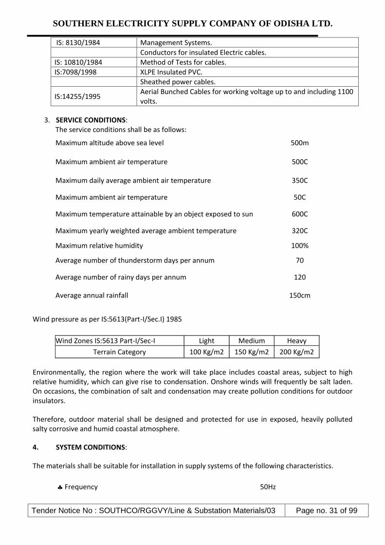
Tender Notice No : SOUTHCO/RGGVY/Line & Substation Materials/03 Page no. 31 of 99
IS: 8130/1984 Management Systems.
Conductors for insulated Electric cables.
IS: 10810/1984 Method of Tests for cables.
IS:7098/1998 XLPE Insulated PVC.
Sheathed power cables.
IS:14255/1995 Aerial Bunched Cables for working voltage up to and including 1100 volts.
3. SERVICE CONDITIONS: The service conditions shall be as follows:
Maximum altitude above sea level 500m
Maximum ambient air temperature 500C
Maximum daily average ambient air temperature 350C
Maximum ambient air temperature 50C
Maximum temperature attainable by an object exposed to sun 600C
Maximum yearly weighted average ambient temperature 320C
Maximum relative humidity 100%
Average number of thunderstorm days per annum 70
Average number of rainy days per annum 120
Average annual rainfall 150cm
Wind pressure as per IS:5613(Part-I/Sec.I) 1985
Wind Zones IS:5613 Part-I/Sec-I Light Medium Heavy
Terrain Category 100 Kg/m2 150 Kg/m2 200 Kg/m2
Environmentally, the region where the work will take place includes coastal areas, subject to high relative humidity, which can give rise to condensation. Onshore winds will frequently be salt laden. On occasions, the combination of salt and condensation may create pollution conditions for outdoor insulators.
Therefore, outdoor material shall be designed and protected for use in exposed, heavily polluted salty corrosive and humid coastal atmosphere.
4. SYSTEM CONDITIONS:
The materials shall be suitable for installation in supply systems of the following characteristics.
Frequency 50Hz

SOUTHERN ELECTRICITY SUPPLY COMPANY OF ODISHA LTD.
Tender Notice No : SOUTHCO/RGGVY/Line & Substation Materials/03 Page no. 32 of 99
Nominal System Voltage 400/230V
Maximum System Voltage LV System 440/250 V
Minimum LV Voltage 370 V
Power frequency one minute withstand(set & dry) 2KV
Neutral Earthing arrangement LV System Solidly earthed
5. GENERAL/ TECHNICAL
The design of Aerial Bunched Cable offered shall comprise a compacted, standard, hard drawn H2 / H4 grade aluminum phase conductor as applicable under IS-8130 / 84 with cross linked polyethylene (XLPE) insulation 0.65 to 1.1. KV class, having of carbon black content 2.5% ± 0.5%.
The sizes and number of cores required are:
3x35mm2 + 1x25mm2
The type of Bunched Cables shall be three phase insulated bundled. All Aluminum Conductors combined with a neutral and catenaries (bare) which shall be of heat treated aluminum magnesium silicon alloy wires containing approximately 0.5% each of magnesium and silicon respectively. The catenaries must have an ultimate tensile stress of not less than that specified in the table of technical requirements.
The conductor bundle offered shall be designed to meet the requirements set out in this specification taking note of safety factors pertaining to conductor and NESC specification: General Technical Requirements for LV overhead lines.
6. CONDUCTORS:
The phase conductors shall be of multi-stranded aluminum of compacted circular cross section. The aluminum shall comply with IS 8130:1984. The messenger conductor shall be of multi-stranded Aluminum Alloy conforming to IS 398 ( Part 4 ) – 1994.
In addition to meeting all requirement of relevant ISS the LT XLPE AB Cables supplied shall satisfy following general requirements.
FOR PHASE CONDUCTORS:
Sl.No. Specified Cross Section Area (mm2)
No. of strands
Min. Dia of each strand in
mm
Min. overall dia.
of conducting
part
Maxm. D.C Resistance at
20 degree centigrade.( Ohm / Km)
Nominal Insulation thickness
(mm)
1 35 7 2.54 7.62 As per ISS/GTP 1.2

SOUTHERN ELECTRICITY SUPPLY COMPANY OF ODISHA LTD.
Tender Notice No : SOUTHCO/RGGVY/Line & Substation Materials/03 Page no. 33 of 99
FOR MESSANGER CONDUCTORS
Sl. No.
Phase conductor size of LT AB Cable in mm2
Specified Cross
Section Area
(mm2) of the
Messenger conductor
No. of strands
Nominal dia. of each
strand
Min overall dia. Of conducting
part of the compacted
conductor(mm)
Maxm. D.C Resistance
of the messenger
at 20 degree centigrade.( Ohm / Km)
Approx. Mass
(Kg/Km) for the
messenger
1 25 7 2.14 6.42 As per ISS/GTP
65
6.0 The bidder must take required precaution to ensure that the average diameter of each strand of conductor shall be ascertained through physical measurement of dimensions of finished cables at ambient temperature during pre-dispatch inspection or / and verification at SOUTHCO Store by consignee and the value so obtained shall have a tolerance limit with reference to the nominal diameter of each strand of conductor as stated in the tables above.
7.0 TOLERANCES:
The measurement of strand diameter of the finished AB Cable shall not be less 0.03mm for strands up to and including 3.00mm diameter. For strands above that size, measurement of strand diameter shall not be less than 1% of the nominal strand diameter.
For the purpose of checking compliance with the above requirement, the diameter shall be determined by two measurements at right angles taken at the same cross section. The physical measurement of strands shall be conducted after opening the strands of a finished AB Cable offered for inspection.
8.0 SPLICES IN WIRES:
Splices in Wires shall generally comply with requirements of IEC 1089.
The aluminum alloy rods may be spliced by cold pressure but welding before drawing provided the manufacturer can guarantee that the splice can develop 90% of the tensile strength of the un sliced rod. Wires which break during stranding may be sliced by cold pressure butt-welding provided that:
No two splices in the completed conductor occur within 15m of each other and no two splices in any individual wire are less than 150m apart.
The splice shall be done with high skilled workmanship. The finished splice shall be smooth and at no point shall the cross sectional area be less than that of the un sliced wire.
Splicing of the alloy wires on the stranding machine in order to utilize lengths of wires on reels shall not be permitted.
9.0 STRANDING AND CORE LAY:
The conductor cores shall be stranded and the direction of lay must be as defined in IEC: 1089.

SOUTHERN ELECTRICITY SUPPLY COMPANY OF ODISHA LTD.
Tender Notice No : SOUTHCO/RGGVY/Line & Substation Materials/03 Page no. 34 of 99
10.0 INSULATION:
The Aerial Bunched Cables shall be insulated for a voltage class of 0.65/1.1 KV and shall be capable of operating permanently at 1.2KV.
The insulation wall thickness shall be determined in accordance with Table-4 (Clause- 7.2 and Clause 7.3) of IS: 14255/1995.
The insulating material shall be black and suitable to resist ultra violet radiation, salt laden sprays,
chemical pollution, ageing effects, abrasion and mechanical shocks and mechanical and electrical
stress at temperature up to 90˚C in normal operation and 2500C under short circuit conditions per
IEC: 502/1994.
The carbon black content in the XLPE insulation shall be 2.5% ± 0.5%
11.0 PHASE IDENTIFICATION:
The individual insulated conductors within a bundle shall be identified by means of longitudinal projections.
The three phase conductors shall be marked by one, two or three longitudinal projections, indicating the red, yellow and blue phases.
The projections shall have the following dimensions.
The distance between the tips of two adjacent projections, where there is more than one, shall be between 1.0 and 1.5.
The width of the projection at the base shall be 1.0mm; and
The height of the projections shall be 0.5mm.
12.0 INSULATION MARKINGS:
Each individual conductor comprising a bundle shall have the range of non-erasable distinct markings listed below legibly printed on the insulation surface at one meter intervals. The embossing should be very clear & easily visible to naked eye.
ISI Mark, IS 14255-95, Manufacturers B.I.S License No. legibly embossed on the insulation.
Name of the Purchaser.
P.O No. & Date
Manufacturer‟s trademark identification for example “UCXLPE50”
Year of manufacture: last two digits are sufficient:

SOUTHERN ELECTRICITY SUPPLY COMPANY OF ODISHA LTD.
Tender Notice No : SOUTHCO/RGGVY/Line & Substation Materials/03 Page no. 35 of 99
Designation of conductor type
Size: for example “3x35”
Shape of conductor.
Rated voltage class: 0.65/1.1KV
Back up conductor identification: conductors with one, two and three projections shall be marked R, Y and B respectively. The conductor with no projection shall be marked N and
The height of the printed lettering shall be not less than 20% of the overall diameter of the conductor
13.0 TWIST:
The direction of lay of the conductors comprising the bundle shall be right-handed and the lay ratio shall comply with IEC: 1089.
With a bare catenaries configuration the insulated phase cables together with the street lighting cores shall be twisted round the neutral catenaries to form the ABC. This cable bundle is then strung directly onto the distribution poles supported by the catenaries with standard approved hardware.
14.0 CABLE DRUM LENGTH:
The cable shall be supplied in 500m. Drum Lengths as the case may be for different sizes of LT XLPE AB Cable.
15.0 TESTS:
15.1 General
Where not specified, all tests and test results shall conform to the requirements of IEC 502/1994 or IS 7098 (Part-I) 1998, IS 10810/1984, IS: 398(Part-IV) and IS: 14255/1955.
Unless expressly stated otherwise, the ambient temperature for routine tests as well as voltage tests shall be 20 + 150C and for all other tests be 20 + 150C.
The frequency of the alternating test voltage shall be 49 Hz to 51Hz. The voltage wave form should be sinusoidal.
15.2 Type Tests
The Type Test report to be submitted by the bidder should contain the reports of following tests:
Insulation resistance at ambient temperature.
Insulation resistance at operating temperature.
AC voltage test.

SOUTHERN ELECTRICITY SUPPLY COMPANY OF ODISHA LTD.
Tender Notice No : SOUTHCO/RGGVY/Line & Substation Materials/03 Page no. 36 of 99
The insulation resistance test at ambient temperature shall be carried out in a water bath at ambient temperature.
The insulation resistance test at a operating temperature shall be conducted in a water bath at 900C.
The longitudinal projections used for phase identification shall be ignored. The results of this test shall be used to calculate the volume receptivity and the results conform to the requirements of IEC:502/1994 or IS 10810 (Part-43).
The AC voltage test shall be carried out by applying 1.95KV (3U0) for four hours to the sample, which shall be submerged in a water bath at ambient temperature, having been steeped for a period not less than one hour. The test shall only be deemed to have been passed if no breakdown occurs.
Furthermore, the following non-electrical type tests shall also be carried out:
Insulation wall thickness: the longitudinal projections used for phase 1 identifications shall be ignored as per IS 10810 (Part-6);
Ageing test, consisting of an evaluation of the retention of the mechanical properties of the insulation after ageing.
Wrapping test: as per IS 10810 (Part-3);
Tests for bleeding and blooming of pigment as per IS 10810 (Part-9)
Thermal expansion of insulation.
Measurement of carbon black content as per IS 10810 (Part-32).
Water absorption by the XLPE insulation, shrinking of the XLPE insulation.
Tensile test: adhesion between conductor and insulation.
The adhesion test requires a tensile testing machine. A sample of at least 300mm length shall be selected and straightened out. The insulation shall be removed for a length of 150mm. The insulated end shall be held in the upper grip head and the bare conductor on the lower grip head. Tension shall be applied at a speed of 500mm/ min until the conductor first begins to slide within the insulation. The test shall have been passed if the conductor and insulation combination can stand 75N/mm2 without slippage occurring.
The neutral conductor/catenaries shall be type tested in accordance with the requirements of IS 398 (Part-IV) 1994.
15.3 Routine Tests
The following measurement or tests shall be carried out on all drums and coils of Bunched cable:
Conductor resistance Voltage test.

SOUTHERN ELECTRICITY SUPPLY COMPANY OF ODISHA LTD.
Tender Notice No : SOUTHCO/RGGVY/Line & Substation Materials/03 Page no. 37 of 99
The conductor to be tested for conductor resistance shall be stored for at least 12 hours in a room at particular constant temperature. If it cannot be established that the conductors have reached the room temperature, the test should be postponed for a period of further 12 hours. Alternatively, the test can be carried out on short sample after remaining one hour in a temperature controlled water bath. The test shall be carried out and the conversion factors used to convert the resistance value to a base of 2000C and one Km. The DC resistance of each conductor shall not exceed the appropriate maximum values specified in IEC:228/IS:6474.
The voltage test shall be conducted by applying to each core 3.5KV AC (2.5 U0 plus 2 KV) or 8.4 KV DC for 5 minutes with the specimen lying in a water bath at ambient temperature. The conductor shall pass the test if no electrical breakdown occurs.
15.4 Acceptance Tests
The following sample check, measurements and test shall be carried out in addition to the Acceptance Tests as per IS 14255 – 1955, IS : 398 ( Part – IV ) 1994, IS 8130 / 1984
Measurement of insulation wall thickness;
Measurement of diameter of each strand, overall outside dia & Cross Sectional Area of the conducting Part out of the finished product during pre-dispatch inspection.
Thermal expansion test;
Check of physical characteristics
Tensile strength of individual wires of conductor.
High Voltage Test on drums immersed in water (apply voltage 3.5 KV AC for 5 min)
These tests should be carried out on one length form each production batch of the same sample.
The thickness of the insulation wall shall be measured on a piece removed from each end of the sample length. If either means or minimum values are not met, two further samples shall be removed at 0.5m form the end corresponding to the failed specimen. If these samples do not satisfy the mean and minimum thickness requirements, the test shall be deemed to have been failed.
The longitudinal projections used for phase identifications shall be ignored. The thermal expansion test need only be carried out on one core.
In relation to the tensile test, the tensile strength of the aluminum wires before stranding and that of the finished conductor shall comply with IEC:1089.
15.5 Test on the Catenary (messenger) Conductor
Breaking load, elongation and resistance tests shall be completed on the aluminum alloy catenaries conductor in accordance with the requirements of IS:398 (Part- IV)/1994 or IEC:1089.

SOUTHERN ELECTRICITY SUPPLY COMPANY OF ODISHA LTD.
Tender Notice No : SOUTHCO/RGGVY/Line & Substation Materials/03 Page no. 38 of 99
15.6 Bending Test on a complete cable
This test shall be performed on a sample of completed cable. The sample shall be bent around a test mandrel at room temperature for at least on turn. It shall then be unwound and the process shall be repeated after turning the cable sample around its axis by 1800. This process shall be repeated twice more. There shall be no signs of breaking or cracking of the cable insulation during this test.
The diameter of the mandrel shall be: 10 (D+d)
Where D = Actual diameter of the cable (mm) d = Actual diameter of the conductor (mm)
16.0 COMPLIANCE WITH SPECIFICATION:
The Aerial Bunched Cable shall comply in all respects with the requirements of this specification. However, any minor departure from the provisions of the specification shall be disclosed at the time of bidding in the Non-compliance Schedule of this document.
17.0 COMPLIANCE WITH REGULATIONS:
All the cables shall comply in all respects with the Indian Regulations and Acts in force. The cables and connections shall be designed and arranged to minimize the risk of fire and any damage, which might be caused in the event of fire.
18.0 Non-conforming Product
The Purchaser reserves the right for decisions regarding acceptance, modification or rejection of non-conforming items.
19.0 Inspection and Testing
The Purchaser or his authorized representative has free entry at all times, while work on the contract is being performed, to all parts of the manufacturers works which concerns the processing of the cables ordered. The manufacturer shall afford the purchaser or his authorized representatives without charge, all reasonable facilities to ensure that the cable being furnished is in accordance with these specifications.
The cables shall successfully pass all the type tests, routine tests & acceptance Tests referred to in the section on tests and those listed in the most recent edition of the standards given in the specification.
The Purchaser reserves the right to reject any of the cables if the test results do not comply with the values specified or with the date given in the Technical data schedule.
Type Test Certificates for the tests conducted earlier shall be submitted with the bid for evaluation. The requirements of additional type tests will be at the discretion of the Purchaser
The Purchaser may witness routine and acceptance tests. In order to facilitate this, the contractor shall give the purchaser of 15days notice that the material is ready for inspection & testing. The supplier shall extend all assistance to the representative of the Purchaser during his inspection &
SOUTHERN ELECTRICITY SUPPLY COMPANY OF ODISHA LTD.
Tender Notice No : SOUTHCO/RGGVY/Line & Substation Materials/03 Page no. 39 of 99
testing of samples at his works. The materials shall be dispatched only after approval of such Test Reports and issue of Despatch clearance by the Purchaser. However the Purchaser reserves the right to retest the materials after delivery at any NABL Accredited Testing Laboratory in case of any disputes regarding size & quality of supplied materials at a later date during guarantee period. The cost of such retesting shall be borne by the supplier.
All costs in connection with the testing, including any necessary retesting shall be borne by the Contractor, who shall provide the Purchaser with all the test shall have the right to select the samples for test and shall also have the right to ensure that the testing apparatus is correct. Measuring apparatus for routine tests shall be calibrated at the expense of the contractor at an approved laboratory and shall be approved by the purchaser before testing.
The Contractor shall be responsible for the proper testing of the materials supplied by sub- Contractor to the same extent as if the materials were completed or supplied by the contractor.
Any cost incurred by the Purchaser in connection with inspection or retesting as a result of failure of the equipment under test or damaged during transport or off loading shall be to the account of the Contractor.
The Contractor shall submit to the Purchaser three signed copies of the test Certificates, giving the results of the tests as required. No materials shall be dispatched until the Purchaser has received the test certificate and the contractor has been informed that they are acceptable.
The test certificate must show the actual values obtained from the tests, in the units used in this specification, and most merely confirm that the requirements have been met.
In the case of components for which specific type tests or routine tests are not given in this specification, the Contractor shall include a list of the tests normally required for these components. All materials used in the Contract shall withstand and shall be certified to have satisfactorily passed such tests.
No inspection or lack of inspection or passing by the Purchaser’s representative of equipment or materials whether supplied by the Contractor or sub- Contractor, shall relieve the contractor from his liability to complete the contract works in accordance with contract or exonerate him from any of his guarantees.
20.0 GUARANTEE:
The contractor shall guarantee the following:
Quality and strength of materials used.
Satisfactory operation during the guarantee period of 24 months from the date of commissioning or 30 months from the date of receipt of the cables at SOUTHCO, whichever is earlier.
Performance figures as supplied by the bidder in the technical data sheet.
21.0 PACKING AND SHIPPING:

SOUTHERN ELECTRICITY SUPPLY COMPANY OF ODISHA LTD.
Tender Notice No : SOUTHCO/RGGVY/Line & Substation Materials/03 Page no. 40 of 99
The cable shall be wound on strong drums or reels capable of withstanding all normal transportation and handing.
GUARANTEED TECHNICAL PARTICULARS FOR LT XLPE AB CABLES
Sl.No Description 3X 35 + 1X25mm2 Bidders’ Offer
requirement
1. Ref. ISS / IEC followed IS 14255/95, IS 398 Part IV
2. Phase Conductor material / Insulation type
H2 / H4 E.C grade aluminium as per IS8130/84 / XLPE insulation ( IS
14255/95)
3. Material of Neutral Catenary Aluminum alloy as per IS 398 Pt
4. Voltage Class 0.65/1.1 KV
5. No. of Strands of Phase conductor 7
6. No. of strands/ Average Strand Dia. in mm. (Finished Phase conductor.)
7/2.54
7. Minimum Overall Dia. of compacted phase conductor after removal of
insulation. (in mm.) 7.62
8. No. of Strands / Average Strand Dia. in mm. (Neutral Catenary.)
7/2.14
9. Minimum Overall Dia. Of compacted Bare Neutral Caternary (in mm.)
6.42
10. Minimum average thickness of insulation of phase Cond. (mm)
1.2
11. Minimum thickness of insulation of Phase Cond. at any point (mm )
0.98
12. Maximum DC resistance of Phase conductor at 20 o C ohm/ KM
0.868
13. Maximum DC resistance of Neutral conductor ohm/ KM
1.38
14 Ultimate tensile strength of neutral conductor(KN)
7
15 Maximum temperature(Continuous)
90°C for phase and 75 °C for neutral
16
Embossing on insulation at each one meter interval
Distinct Non- erasable ISI Mark, IS 14255-95, Manufacturer’s B.I.S
License No., Name of the Purchaser, Name of the
manufacturer, Size of cable, voltage Grade along with sequential
marking of length.
17 Cable drum length 500m
18 Volume Resistivity of insulation at 27°C
1X10¹³Ώ – cm min.
19 Volume Resistivity of insulation at 70°C
1X10¹¹Ώ – cm min.

SOUTHERN ELECTRICITY SUPPLY COMPANY OF ODISHA LTD.
Tender Notice No : SOUTHCO/RGGVY/Line & Substation Materials/03 Page no. 41 of 99
N.B:
1) For values not available in relevant ISS, values indicated in our GTP/ Tender Specification shall be
valid.
2) In case of discrepancies between values of ISS & GTP, better will prevail.
3) Average diameters of strands of each cable shall be ascertained by physical measurement after
opening the strands of each phase of a finished AB Cable offered for inspection.

SOUTHERN ELECTRICITY SUPPLY COMPANY OF ODISHA LTD.
Tender Notice No : SOUTHCO/RGGVY/Line & Substation Materials/03 Page no. 42 of 99
Group – C : a) 11 KV 200 Amp 3 Pole AB Switch (Horizontal)
Technical Specification 01.0 Scope: -
This specification covers manufacturing testing and supply of 11KV 200 AMPS 50HZ Air Break
switches for out door installation in horizontal configuration. The switches are suitable for
operation under off load conditions only and are intended for use on Distribution Sub –
stations and tapping sectionalizing points of 11 KV lines.
02.0 Description of the materials: -
The 11KV A.B. Switch sets shall confirm to the following parameters: - a) Number of poles 3 b) Number of Post insulator per pole 2nos12KVpostinsulator. c) Nominal system voltage 11KV d) Highest system voltage 12KV e) Rated frequency 50Hz f) System earthling effectively earthed. g) Rated nominal current 200 amps h) Altitude of installation Not exceeding1000M
03.0 Standards: -
The AB Switch Set shall conform to the following standards: - a) IS-9920 (Part-I to V) b) IS-2544/1973 (for porcelain post insulators) c) IS-2633, (for galvanization of ferrous parts.) or its latest amendments if any.
04.0 Insulator make: -
12KV post insulators complete with post and cap duly cemented to be used in the AB Switch Set conforming to IS-2544/1973. The bidder shall furnish the type test certificate of the post insulators from their manufacturer for reference and scrutiny. The bidder shall mention make, type of insulation materials, metal fittings, Creepage distance, protected Creepage distance, tensile Strength, compressing strength, torsion strength and cantilever strength.

SOUTHERN ELECTRICITY SUPPLY COMPANY OF ODISHA LTD.
Tender Notice No : SOUTHCO/RGGVY/Line & Substation Materials/03 Page no. 43 of 99
05.0 Climatic condition: -
The A.B. Switch set shall be suitable for operation under the following climatic conditions.
a) Maximum ambient air temperature 45 o C b) Maximum daily average air temperature 35 o C c) Maximum yearly average ambient air temperature 30 o C d) Maximum temperature attainably by a body e) Exposed to the Sum. 50 o C f) Minimum ambient air temperature 0 o C g) Maximum relative humidity 100% h) Minimum number of rainy days per annum 70 i) Average number of rainy days per annum 120 j) Average annual rain fall 150cm. k) Number of months of tropical monsoon conditions 4 l) Maximum wind pressure 260Kg./mm2 m) Degree of exposure to atmospheric pollution normally n) Atmosphere. Polluted.
6.0 TEST & TEST CERTIFICATE: - 06.01 Type Test: - Certificate for the following type tests conducted on a prototype set of A.B.
Switch in a NABL approved test house/CPRI shall have to be submitted along with offer. Dielectric Test (impulse and one minute were power frequency withstand voltage test.)
Temperature rise test (for contracts and terminals)
Shorts Time current and peak withstand current test.
Mainly active load breaking capacity test.
Transformer off-load breaking capacity test.
Line charging breaking capacity test.
Cable charging breaking test.
Operation and mechanical endurance test.
Mechanical strength test for post insulator, as per IS-2444/1937 shall be furnished.
Test for galvanization of metal (ferrous) parts.
06.02 Routine /Acceptance Test: -
The inspection may be carried out by the Purchaser at any stage of manufacture. The successful bidder shall grant free access to the Purchaser’s representative at a reasonable time when the work is in progress. The following routine tests shall have to be conducted on each set and results are to be furnished for consideration of deputing inspecting officer for inspection and conduction testing of the materials at the works of the manufacturer. The supplier shall give fifteen days advance intimation to the Purchaser to enable him to depute his representative for witnessing the tests. 1. Power frequency voltage dry test. 2. Measurement of resistance of main circuit. 3. Tests to prove satisfactory operation.

SOUTHERN ELECTRICITY SUPPLY COMPANY OF ODISHA LTD.
Tender Notice No : SOUTHCO/RGGVY/Line & Substation Materials/03 Page no. 44 of 99
4. Dimension Check 5. Galvanization test. 6. Operational test.
07.00 Guaranteed Technical Particulars: - The bidder shall furnish the guaranteed technical particular duly filled in the format along with the tender.
8.0 Completeness of Equipment: - All fittings, accessories of apparatus which may not have been specifically mentioned in this specification but which are usual or necessary in equipment of similar plat shall be deemed to be included in the specification and shall be supplied by the Tender without extra charge. All plant and equipment shall be completed in all details whether such details are mentioned in the specification or not.
GUARANTEED TECHNICAL PARTICULARS
Sl. No Particulars Requirement Bidders offer
List of relevant standards : IS 1818,9921,2544,1394,4691,325, 4722, 2629, 4759, 2633, 1573,3033, 2016, 3961, 5561, 1554, 5578,11353,9920
1 Maker’s name & Address To be specified by the bidder
2 Type of Switch Rotating Type
3 Suitable for mounting Horizontal only
4 No. of Breakers per phase
Single Break
5 No. of Post Insulators per phase
2nos. of 12KV Post Insulators as per IS:2544/73 per phase
6 (a)
Post Insulators Maker’s Name & Country of Manufacture of Post Insulator
To be specified (as per CPRI Test Report).
(b) Type of cementing Original Cemented only & as per ISS 2544/1973 & relevant IEC
(c) One minute Power frequency withstand voltage (Dry)
35 KV RMS
(d) One minute Power frequency withstand voltage (wet)
35 KV RMS
(e) Visible discharge voltage 9KV RMS
(f) Dry flash over voltage 85 KV RMS
(g) Power frequency 110KV

SOUTHERN ELECTRICITY SUPPLY COMPANY OF ODISHA LTD.
Tender Notice No : SOUTHCO/RGGVY/Line & Substation Materials/03 Page no. 45 of 99
puncture withstand voltage
(h) Creepage distance(min.) 320 mm
(7) Impulse withstand voltage for positive & negative polarity (1.2/50 micro second wave)
(a) Across the isolating distance
85KV Peak
(b) To earth & between poles
75KV Peak
8 Rated one minute Power frequency withstand voltage
(a) Across the Isolating distance
32KV(RMS)
(b) To earth & between poles
28KV(RMS)
9(a) Rated voltage nominal/maximum
11/12KV
(b) Rated normal current and rated frequency
200 Amps. 50hz
10 Rated short-circuit making capacity
25 KA (Peak)
11 Rated Short-time current 10KA RMS
12 Rated peak withstand current
40 KA(peak)
13 Rated mainly active load breaking capacity
200 Amp. RMS
14 Rated transformer off load breaking capacity
6.3A
15 Rated line charging capacity
2.5 A (RMS)
16 Minimum clearance between adjacent phase
(a) Switch closed (center to center)
760 Mm
(b) Switch opened (Center of post insulator to the edge of the blade)
380 Mm
18 Temperature rise The Temperature rise should not exceed the maximum limit to 65oC at an ambient temperature not exceeding 40oC
The Temperature rise of contacts & terminals are within permissible limit of 650C & 50oC respectively.
19 Vertical clearance from 254 mm (Min.)

SOUTHERN ELECTRICITY SUPPLY COMPANY OF ODISHA LTD.
Tender Notice No : SOUTHCO/RGGVY/Line & Substation Materials/03 Page no. 46 of 99
top of insulator cap to mounting channel
20 Type of contact a) Self aligned high pressure law type fixed contacts of hard drawn copper of size 65x35x6 mm contact is riveted with three nos. copper rivets with a bunch (min. 3 mm thick) consisting of copper foils , each may vary from 0.15 mm to 0.25 mm . The total thickness of copper foils per Jaw should be 6 mm. Jaw assemblies are to be bolted through stainless steel bolts & Nuts with stainless steel flat and spring washer.
b) Solid rectangular blade type moving contact of electrolytic copper size 35x6 mm and length 220 mm duly silver plated ensuring a minimum deposit of 10 micron of silver on copper contacts or as may be prescribed under relevant ISS/IEC.
c) Stainless Steel 4 NOS of Pressure springs are to be used in each jaw contacts having 8nos. of turns X28mm heights X14.4mm diameter with 14 SWG wire
21 Connectors Terminal Connectors for both movable & fixed should be of copper flats of same size similar to that of moving contact blades (min. 95 % copper composition). The fixed Connector shall of size 65x35x6 mm and the size of movable connector shall be size 65x35x6 mm with machine finishing duly silver plated with 2 nos. of 3/8” stainless steel bolts, nuts, plain washers & spring washers should be provided along with two nos. Solder less bimetallic sockets for each connector suitable up-to 55 mm2 Conductor.
22 Moving Contact Movable contact is to be supported by galvanized angle of 45x45x5 mm in eah phase and moving contacts are to be bolted through two nos. stainless steel bolts and nuts with suitable stainless steel flat & spring washers.
23 Galvanization (a) Iron parts shall be hot dip galvanized as per IS 2633/1972.
(b) The pipe shall be galvanized as per IS 4736/1968.
(c) All non-ferrous parts should be duly electroplated with silver.
24 (a)
Phase Coupling Rod ISI mark 25mm nominal bore G.I. Pipe (Medium) conforming to IS:1239/Part

SOUTHERN ELECTRICITY SUPPLY COMPANY OF ODISHA LTD.
Tender Notice No : SOUTHCO/RGGVY/Line & Substation Materials/03 Page no. 47 of 99
(b) Operating Rod ISI mark 32mm nominal bore G.I. Pipe (Medium) of 6mtr single length.
Nominal Bore (GI Pipe) 25 mm 32mm
O.D.Diameter Thickness Max. Min. 34.2mm 33.3 mm 3.25 mm 42.9 mm 42 mm 3.25 mm
(c) Arcing Horn 8 mm dia G.I. Rod with spring assisted operation.
(d) Force of fixed contact spring
50 lbs to 75 lbs
(e) Copper braided flexible taps
320mm length of flexible electrolytic copper tape or braided chord (with tin coated) having minimum wt. of 450 gm. Per mtr. and both ends shall be crimped with copper sockets through brass bolts & nuts with brass flat washers. The min. no. of flexible wires should be 1536 of 36 SWG for each flexible chord.
(f) Quick break device Lever mechanism
(g) Bearings 4 nos. self lubricated bearing to be provided with grease nipple including 4th bearing being a thrust bearing.
(h) Locking Arrangements Pad locker & Key arrangement at both “ON” & “OFF” position.
(i) Earth Terminal To be provided at base channel
25 Supporting Channels 75x40 mm MS Channel of Hot dip galvanized
26 Weight of each Pole complete in Kg.
To be specified by the bidder
27 Detailed drawing submitted?
To be submitted by bidder with detail construction & material of different parts
GROUP – C (b) 11 KV, 400 Amp. 3 poles HG Fuse
1. SCOPE:- This specification covers the manufacture, testing and supply of 11 KV,400 Amps 3 pole, H.G. Fuse Sets.
2. (a) The 11 KV H.G. Fuses shall be suitable for outdoor operation in horizontal configuration under the climatic conditions specified. It shall be of the following ratings:-
1 Number of Poles 3
2 No. of Insulator per Pole 2 nos. 12 KV post Insulators
3 Nominal system Voltage 11 KV
4 Highest System of Voltage 12 KV
5 Rated frequency 50 Hz
6 System Frequency Effectively earthed
7 Rated normal current 400 Amps
8 Altitudes of installation Not exceeding 1000 M.

SOUTHERN ELECTRICITY SUPPLY COMPANY OF ODISHA LTD.
Tender Notice No : SOUTHCO/RGGVY/Line & Substation Materials/03 Page no. 48 of 99
(b) The post insulator used in the H.G. Fuse set shall have the following ratings:-
1 Power frequency withstand voltage (dry) 35 KV (RMS)
2 Power frequency withstand voltage (wet) 35 KV (RMS)
3 Impulse withstand voltage (dry) 75 KV (Peak)
4 Power frequency withstand voltage 1.3 times the actual dry flashover voltage of the unit
3. STANDARDS :-
The H.G. Fuse set shall confirm to the following standards. IS- 9385-1980 ( for high voltage expulsion fuses and similar fuses). IS- 2544-1973 ( for porecelain post insulators or its latest amendments if any.). IS- 2633-1979 ( for Galvanisation of ferrous parts).
4. INSULATOR MAKE: - 12 KV post insulator complete with pedestal cap duly cemented to be used in 11 KV H.G. Fuse sets confirming to IS-2544/1973.
5. TECHNICAL DETAILS: - The H.G. Fuses shall have adjustable arcing horns made of solid copper rod
having 7.62 mm dia. The horns shall be fitted with screwing devices with flynuts for fixing and tightening the fuse wire. It shall have robust terminal connector 5s of size 80 mm x 50 mm x 8 mm made of copper casting ( 95 % minimum copper composition) duly silver plated with two numbers of 12 mm dia brass bolts and double nuts with flat brass washers. The connectors should be capable of connecting crimpable conductor up-to 80 Sq. mm size (ACSR/ Alloy) with bimetallic solder less sockets. The H.G Fuse Set shall suitable for horizontal mounting on substation structures. The minimum clearance between the adjacent phases of the fuse set shall be 760 mm and the centre to centre (distance between two post insulators of the same phase) shall be 410 mm. All metal (ferrous) parts shall be galvanized and polished. Only 12 KV post insulator (original cemented and not pin insulators shall be used for the H.G. Fuse Set.
6. CLIMATIC CONDITIONS: - The H.G. fuse set shall be suitable for operation under the following
climatic conditions:-
1 Maximum ambient air temperature 450 C
2 Maximum daily average air temperature 350 C
3 Maximum yearly average ambient air temperature 300 C
4 Maximum temperature attainable by a body exposed to the sun.
500 C
5 Minimum ambient air temperature 00 C
6 Maximum relative humidity 100%
7 Average number of thunderstorm days per annum 70 DAYS
8 Average number of rainy days per annum 120
9 Average annual rain fall. 150CM
10 Number of months of tropical monsoon conditions 4
11 Maximum wind pressure 260 Kg/mm
12 Degree of exposure to atmospheric pollution. Normally polluted atmosphere.
SOUTHERN ELECTRICITY SUPPLY COMPANY OF ODISHA LTD.
Tender Notice No : SOUTHCO/RGGVY/Line & Substation Materials/03 Page no. 49 of 99
7 Type Test:-
Certificate for the following type tests conducted on a prototype set of HG Fuse in a NABL approved test house/CPRI shall have to be submitted along with offer.
a) Dielectric test (impulse & one minute wet power frequency withstand voltage test.) b) Temperature rise test ( for terminals) c) Mechanical strength test for the post of insulator as per IS-2544/1973 d) Test for galvanization of metal (ferrous) parts.
8. ROUTINE/ACEPTANCE TESTS:-
The inspection may be carried out by the Purchaser at any stage of manufacture. The successful bidder shall grant free access to the Purchaser’s representative at a reasonable time when the work is in progress. The following routine tests shall have to be conducted on each set and results are to be furnished for consideration of deputing inspecting officer for inspection and conduction testing of the materials at the works of the manufacturer. the supplier shall give fifteen days advance intimation to the Purchaser to enable him to depute his representative for witnessing the tests.
a) Power frequency voltage dry test b) Dimension Check c) Galvanization test.
9. Guaranteed Technical Particulars:
The bidders are required to furnish the guaranteed technical particulars duly filed in the proforma along with the bid.
10. Completeness of Equipment:
Any fittings accessories or apparatus which may not have been specifically mentioned in this specification but which are usually necessary in equipment of similar plant shall be deemed to be included in the specification and shall be supplied by the bidder without extra charge. All plant and equipment shall be complete in all details whether such details are mentioned in the specification or not.
11. Inspection:
Routine and acceptance test shall be conducted at the place of manufacturer. The bidders are requested to furnish details of equipments which will be used for testing along with the bid. The bids of these manufacturers who do not have adequate testing facilities for conducting routine and acceptance test are liable for cancellation. The successful bidder has to furnish routine test certificate and guarantee certificate for each consignment of materials to be inspected at the time of offer of materials for inspection.

SOUTHERN ELECTRICITY SUPPLY COMPANY OF ODISHA LTD.
Tender Notice No : SOUTHCO/RGGVY/Line & Substation Materials/03 Page no. 50 of 99
GUARANTEED TECHNICAL PARTICULARS
Sl. No. Particulars (Desired Value)
Values offered by the
Bidder
1 Name of the manufacturer and country of origin
To be specified by the bidder
2 Operating voltage 11 KV
3 No. of Insulators per Phase 2 no. s 12 KV Post Insulators per Phase as per ISS 2544/1973
4 Rated normal current and normal frequency
400 Amps. 50 Hz
5 Vertical clearance from top of insulator cap to mounting channel
254 mm (minimum)
6 Height of the riser for carrying the horns
150 mm from the cap (top) of insulator
7 Post Insulator
(a) Name of the manufacturer and country of origin
To be specified by the bidder
(b) Type of cementing To be quoted original cemented only
(c) One minute power frequency withstand voltage - Dry
35 KV RMS
(d) One minute power frequency withstand voltage – Wet
35 KV RMS
(e) Visible discharge voltage 9 KV RMS
(f) Dry Flashover voltage To be specified by the bidder
(g) Power frequency puncture withstand voltage
1.3 times of actual dry flash over voltage
(h) Creepage distance 320 mm minimum (actual creepage distance for which type test has
been conducted is to be specified by the bidder).
8 Impulse withstand voltage (1.2/50 micro second wave positive & negative polarity)
(a) Across the isolating distance 85 KV (peak)
(b) To earth & between poles 75 KV (peak)
9 One minute power frequency withstand voltage
(a) Across the isolating distance 32 KV (RMS)
(b) To earth & between poles 28 KV (RMS)
10 Details of Arching Horns Solid cupper rod having 7.62 mm dia silver plated provided with
screwing arrangement on the fuse carrier made of cupper casting for

SOUTHERN ELECTRICITY SUPPLY COMPANY OF ODISHA LTD.
Tender Notice No : SOUTHCO/RGGVY/Line & Substation Materials/03 Page no. 51 of 99
fixing fuse wire. (Total length 635 mm). All the bolts, nuts and
washers should be made out of brass.
11 Riser Unit (150 mm total height)
Riser cum connector made out of cupper casting 9with minimum 95%
cupper composition) having riser size 50 mm height x 30 mm width x 8 mm thickness and connector size 80x50x8 mm duly silver plated and machine finishing provided with 2 no.s 12 mm dia brass bolts & brass double nuts with flat brass washer
and 2 no.s solder less bimetallic sockets per each connector suitable
upto 100 mm2 conductor.
12 Supporting Channels 75mm x 40mm x 5 mm MS Channel (Galvanized)
13 Galvanization All ferrous parts should be galvanized as per IS-2633/1972 & all
non-ferrous parts should be duly electroplated with silver.
14 Weight of each pole (complete)
To be specified by the bidder
15 Sockets (Lugs) Shall be tinned cupper solder less crimping type confirming to IS :
8309 & 8394 suitable for aluminium conductor. The cable
lugs shall suit the type of terminals provided. The cable lug shall be of
Dowel make.
16 Detailed drawing submitted? To be submitted by bidder
Group D: 11KV LIGHTNING ARRESTOR
TECHNICAL SPECIFICATION
1.0 SCOPE 1.1 This Specification provides for the design, manufacture, inspection and testing before
dispatch, packing and delivery F.O.R. (destination) of metal oxide (gapless) Surge Arresters with discharge counters, insulating base, terminal connectors and other accessories as specified here in.
1.2 The Surge Arrester shall conform in all respects to high standards of engineering,
design, workmanship and latest revisions of relevant standards at the time of offer and purchaser shall have the power to reject any work or materials, which in his judgment is not in full accordance therewith.

SOUTHERN ELECTRICITY SUPPLY COMPANY OF ODISHA LTD.
Tender Notice No : SOUTHCO/RGGVY/Line & Substation Materials/03 Page no. 52 of 99
1.3 STANDARDS:-
Except to the extent modified in the Specification, the Surge Arrester shall conform to the latest editions and amendments of the standards listed hereunder.
Sl. No. Standard
Ref. No. Title.
1 IEC-99-4 Specification for Surge Arresters without gap for AC System.
2 IS:2147 Degree of protection, provided by enclosures for low voltage switchgear and control.
3 IS:2629 Recommended practice for hot dip galvanization of iron and steel.
4 IS:2633 Method for testing uniformity of coating on zinc coated articles.
5 IS:3070 Specification for surge arresters for alternating current system.
6 IS:5621 Specification for large hollow porcelain for use in electrical
& IEC-621155 installation. 7 IEC-60-1 High-Voltage Test technique. 8 IEC-270 Partial discharge measurements. 9 IEC-99-1 Non-linear resistor type gapped arresters for a.c. systems.
10 Indian Electricity Rules, 1956. 11 IEC-60815 Shed profile of hollow porcelain Insulator.
1.4 Surge Arresters with the requirement of other authoritative standards, which ensure
equal or better quality than the standards mentioned above shall also be acceptable. Where the equipment offered by the supplier conforms to other standards, salient points of difference between the standards adopted and the specified standards shall be clearly brought out in the offer. 4 (Four) copies of the reference standards in English language shall be furnished along with the offer.
1.5 GENERAL TECHNICAL REQUIREMENTS:
1.5.1 The Surge Arrester shall confirm the technical requirements. 1.5.2 The energy handling capability of each rating of Arrester offered, supported by
calculations, shall be furnished with the offer. 1.5.3 The Surge Arresters shall be fitted with pressure relief devices and arc diverting paths and
shall be tested as per the requirements of IEC for minimum prospective symmetrical fault current as specified in Appendix-I.
1.5.4 A grading ring shall be provided if required, (for attaining all the relevant technical
parameters) on each complete Surge Arrester. 1.6 DUTY REQUIREMENT:
1.6.1 Surge Arresters shall be of gapless type without any series or shunt gaps and with vertical mounting arrangement.
i. Surge Arresters shall be capable of discharging over voltages occurring during switching of

SOUTHERN ELECTRICITY SUPPLY COMPANY OF ODISHA LTD.
Tender Notice No : SOUTHCO/RGGVY/Line & Substation Materials/03 Page no. 53 of 99
un- loaded transformers, lines, capacitors and reactors.
ii. The Surge Arresters shall be capable of discharging lightning and switching surges and temporary power frequency over-voltages.
iii. The Surge Arresters shall be capable of discharging the energy equivalent to class 3 of IEC-99-4.
1.6.2 The reference current of the arrester shall be high enough to eliminate the influence of grading and stray capacitance on the measured reference voltage. The supplier shall submit values and the supporting evidence along with calculations on above.
1.6.3 Surge Arresters shall be fully stabilized thermally to give a life expectancy as per standard under site conditions.
1.6.4 Surge Arresters shall be able to withstand maximum wind load of 260 Kg./sq.m. 1.6.5 Surge Arresters shall be capable of withstanding effects of direct solar radiation 1.6.6 Surge arresters shall be capable of spark over on severe switching Surges and multiple
strokes. 1.6.7 The Surge Arrester should be adequately designed to operate satisfactorily under
temporary power frequency over-voltage as given in specific technical requirements, after discharging two shots of respective long duration surges.
1.6.8 Unless otherwise brought out separately by the Bidder in the schedule of deviations, the Surge Arresters, offered shall confirm to the specification scrupulously. All deviations from the specification shall be brought out in the schedule of deviations. The discrepancies between the specification and the catalogues or literature, submitted as part of the offer shall not be considered as valid deviations unless specifically brought out in the schedule of deviations.
1.7 CONSTRUCTION: 1.7.1 Non linear blocks shall be sintered metal oxide material. These shall be provided in such a
way as to obtain robust construction with excellent electrical and mechanical properties even after repeated operations.
1.7.2 All the units of arresters of same rating shall be inter-changeable without adversely affecting the performance.
1.7.3 The Surge Arresters shall be suitable for pedestal type mounting.
1.7.4 All the necessary flanges, bolts, nuts, clamps etc. required for assembly of complete arrester with accessories and mounting on support structure to be supplied by the purchaser, shall be included in supplier‘s scope of supply.
1.7.5 The drilling details for mounting the Arrester on owner‘s support shall be supplied by the
supplier. 1.7.6 The minimum permissible separation between the Surge Arrester and any earthed object
shall be indicated by the Bidder in his offer. 1.7.7 Surge Arresters shall be designed to incorporate pressure relief devices and arc diverting
paths to prevent shattering of the blocks or the porcelain housing, following prolonged current flow or internal flash over and providing path for flow of rated fault currents in the event of arrester failure.

SOUTHERN ELECTRICITY SUPPLY COMPANY OF ODISHA LTD.
Tender Notice No : SOUTHCO/RGGVY/Line & Substation Materials/03 Page no. 54 of 99
1.7.8 Surge Arresters shall incorporate anti-contamination feature to prevent arrester failure, caused by uneven voltage gradient across the stack, resulting from contamination of the arrester porcelain.
1.7.9 Seals shall be provided in such a way that these are always effectively maintained even when discharging rated lightning current.
1.7.10 The heat treatment cycle details along with necessary quality checks used for individual blocks along with insulation layer, formed across each block are to be furnished. Metalised coating thickness for reduced resistance between adjacent discs is to be furnished along with the procedure for checking the same. Details of thermal stability test for current distribution of current on individual disc is to be furnished.
1.7.11 Each individual unit of Surge Arresters shall be hermetically sealed and fully protected against ingress of moisture. The hermetic seal shall be effective for the entire lifetime of the arrester and under the service conditions as specified. The supplier shall furnish sectional view of the arrester showing details of sealing employed.
1.7.12 The Surge Arresters shall be suitable for hot line washing.
1.8 PORCELAIN HOUSING: 1.8.1 All porcelain Housings shall be free from lamination cavities or other flaws, affecting
the maximum level of mechanical and electrical strengths. 1.8.2 The porcelain shall be well vitrified and non-porous.
1.8.3 The minimum creep age distance of the arrester housing shall be as per Cl 7.21 of the TS.
1.8.4 The porcelain petticoat shall be preferably of self-cleaning type (Aerofoil design). The details of the porcelain housing such as height, angle of inclination, shape of petticoats, gap between the petticoats, diameter (ID and OD) etc. shall be indicated by the Bidder in his offer in the form of detailed drawing.
1.8.5 Porcelain housings shall be so co-coordinated that external flash over will not occur due to application of impulse or switching Surge voltages up to the maximum design value for arrester.
1.9 GALVANISATION, NICKEL PLATING ETC.:
1.9.1 All ferrous parts exposed to atmosphere shall be hot dip galvanized as per IS: 2629,
as amended from time to time. Tinned copper/brass lugs shall be used for internal wiring of discharge counter. Screws used for electrical connections shall be either made of brass or shall be nickel-plated.
1.9.2 Ground terminal pads and nameplate brackets shall be hot dip galvanized. 1.10.3 The material shall be galvanized only after completing all shop operations
1.11 ACCESSORIES AND FITTINGS:
1.11.1 Surge Counters
1.11.2 A self- contained Surge counter, suitably enclosed for outdoor use and requiring no auxiliary
of battery supply for operation shall be provided for each unit. The surge counter shall be

SOUTHERN ELECTRICITY SUPPLY COMPANY OF ODISHA LTD.
Tender Notice No : SOUTHCO/RGGVY/Line & Substation Materials/03 Page no. 55 of 99
operated by the discharge current, passed by the surge arrester and shall be suitable for mounting on the support structure of the Arrester.
1.11.3 Surge counters shall be of the Electro-mechanical type and designed for continuous service.
1.11.4 The cyclometer counter shall be visible through an inspection window from ground level.
The counter terminals shall be robust and adequate size and shall be so located that the incoming and outgoing connections are made with minimum possible bends.
1.11.5 Internal parts shall be unaffected by atmospheric conditions at site. Alternatively, a
weather proof housing to IP 55 shall be provided and this shall be designed to allow the recording device to be read from ground level without exposing the internal parts to the atmosphere.
1.11.6 The Surge Counter shall be connected in the main earth lead from the arrester in such a
manner that the direction of the earth lead is not changed or its surge impedance materially altered. A bolted link shall be provided so that the surge counter may be short circuited and removed without taking the arrester out of service.
1.11.7 All necessary accessories and earthing connection leads between the bottom of the Arrester and discharge counter shall be in the supplier‘s scope of supply.
1.12 NAME PLATE:
Each single pole Arrester shall be provided with non-corrosive legible name plate, at the base bearing thereon, voltage rating of the complete pole and the number of demountable sections with the following data, indelibly marked
i) SOUTHCO ii) Purchase order No. & Date. iii) Name of device. iv) Manufacturer‘s name and trademark and identification no. of the arrester being
supplied. v) Year of manufacture vi) Rated voltage vii) Rated Frequency viii) Maximum continuous operating voltage. ix) Type
x) Nominal discharge current. xi) Long duration discharge class. xii) Pressure relief current in KA(rms) xiii) Energy discharge capability (KJ / KV rating).
1.13 TEST:
1.13.1 Type Tests:

SOUTHERN ELECTRICITY SUPPLY COMPANY OF ODISHA LTD.
Tender Notice No : SOUTHCO/RGGVY/Line & Substation Materials/03 Page no. 56 of 99
The surge Arrester offered should have been subjected to the following type tests in an independent NABL Accredited test laboratory. The bidder shall furnish type test reports along with the offer. These tests must not have been conducted within five years before the date of opening of technical bid.
1 Insulation withstands tests: (a) Lightning Impulse Voltage Test. 2 Residual voltage tests. 3 Long duration current impulse withstands tests. 4 Operating duty tests. 5 Pressure relief tests. (a) High current test. (b) Low current test. 6 Power frequency voltage vs. time curve. (Temporary over voltage test) 7 Contamination test. (Artificial pollution test). 8 Seismic withstand test. 9 IP-55 test on surge counter. 10 Minimum current operation tests of the surge counter. 11 Maximum current withstand test of the surge counter. 12 Mechanical terminal load test on bushing. 13 Partial discharge test.
N.B. :- Even if the condition i.e. the dry arcing distance or the sum of the partial dry arcing
distances is larger than the test voltage divided by 500 KV/m‘, the lightning impulse voltage test must have been conducted or is to be conducted without any financial liability to SOUTHCO.
1.13.2 ROUTINE TESTS:
The following routine tests shall be conducted at the supplier‘s cost on each surge arrester and shall be submitted along with or before offering for inspection for purchaser‘s approval.
(a) Measurement of reference voltage.
(b) Residual voltage tests. (c) Measurement for partial discharge and contact noise. (d) Sealing test for units with sealed housings. 1.13.3 ACCEPTANCE TESTS:
The following tests, considered as acceptance tests, shall be conducted in the presence of purchasers representative for which no charges will be payable by SOUTHCO. The acceptance tests, whenever possible shall be conducted on the complete arrester unit. The number of samples to be subjected to acceptance test shall be decided by the purchaser at the time of actual testing.
I Temperature Cycle Test on Housing.
II Measurement of Power Frequency Voltage at the reference current.
III Measurement of leakage current and capacitive current at M.C.O.V.

SOUTHERN ELECTRICITY SUPPLY COMPANY OF ODISHA LTD.
Tender Notice No : SOUTHCO/RGGVY/Line & Substation Materials/03 Page no. 57 of 99
IV Lightning Impulse Residual Voltage Test at N.D.C., 50% of N.D.C. & 200% of N.D.C. V
Partial Discharge Tests on complete arresters/units at 1.05 times M.C.O.V.
VI Special Thermal stability test.
VII Porosity test on porcelain components.
VIII Galvanization test on metal parts.
IX The functional (operational) test on the Surge Counter by way of checking its operation
at following nominal discharge currents :
a) 100 Amps with 8/20 micro second wave shape.
b) 10 KA with 8/20 micro second wave shape.
X Check of calibration of leakage current meters.
1.14 INSPECTION:
I The purchaser inspector shall have access at all time to the works and all other places of manufacture, where the Surge Arresters are being manufactured and the supplier shall provide all facilities for unrestricted inspection of the supplier‘s works, raw materials, manufacture of all the accessories and for conducting the necessary tests.
II The supplier shall keep the purchaser informed in advance of the time of starting and
the progress of manufacture of equipment in its various stages so that arrangements could be made for inspection.
III No material shall be dispatched from its point of manufacture unless the material has
been satisfactorily inspected tested and dispatch schedule attached to this specification.
IV The acceptance of any quantity of equipment shall in no way relieve the supplier of his responsibility for meeting all the requirements of this specification and shall not prevent subsequent rejection, if such equipments are later found to be defective.
1.15 QUALITY ASSURANCE PLAN:
1.15.1 The Bidder shall invariably furnish following information along with his offer, failing
which the offer shall be liable for rejection.
(i) Statement giving list of important raw materials, names of sub-suppliers for the raw materials, list of standards according to which the raw materials are tested, list of tests, normally carried out on raw materials in presence of Bidder‘s representative, copies of test certificates.
(ii) Information and copies of test certificates as in (I) above in respect of bought-out items.
(iii) List of manufacturing facilities available.
(iv) Level of automation, achieved and list of areas where manual processing exists.
SOUTHERN ELECTRICITY SUPPLY COMPANY OF ODISHA LTD.
Tender Notice No : SOUTHCO/RGGVY/Line & Substation Materials/03 Page no. 58 of 99
(v) List of areas in manufacturing process where stage inspections are normally carried out for quality control and details of such tests and inspections.
(vi) Special features provided in the equipment to make it maintenance free.
(vii) List of testing equipments, meters available with Bidder for final testing of
equipment, specified and test plant limitation, if any, vis-à-vis the type, acceptance and routine tests, specified in the relevant standards and this specification. These limitations shall be very clearly brought out in the offer.
(viii) All the testing equipments, meters etc. should have been calibrated in a Government
approved laboratory. The Bidder must submit the list of testing equipments and meters test-wise as per Annexure-C of this Technical Specification.
1.15.2 The suppliers, within 30 days of placement of order submit the following information to
the purchaser.
(i) List of raw materials as well as bought out accessories and the names of the materials as well as bought-out accessories and the names of sub-suppliers, selected from those, furnished along with the offer.
(ii) Type test certificates of the raw material and bought out accessories.
(iii) Quality Assurance Plan (QAP) with hold points for the purchaser‘s inspection. The QAP
and hold points shall be discussed between the purchaser and the supplier before the QAP is finalized.
1.15.3 The supplier shall submit the routine test certificates of bought out item and raw martial
at the time of acceptance testing of the fully assembled equipment.
1.16 DOCUMENTATION: 1.16.1 All drawings shall conform to relevant Indian Standard as per relevant IS. All drawings shall
be in ink and suitable for microfilming. All dimensions and data shall be in S.I. Units.
1.16.2 The supplier shall furnish four sets of following drawings / documents along with his offer.
(i) General outlines drawings of the complete Arrester with technical parameters.
(ii) Drawings showing clearance from grounded and other line objects and between adjacent
poles of Surge Arresters, required at various heights of Surge Arresters.
(iii) Drawings showing details of pressure relief devices.
(iv) Detailed drawing of discharge counters along with the wiring and schematic drawing
of discharge counter and meter.
(v) Outline drawing of insulating base.
vi) Details of grading rings, if used.

SOUTHERN ELECTRICITY SUPPLY COMPANY OF ODISHA LTD.
Tender Notice No : SOUTHCO/RGGVY/Line & Substation Materials/03 Page no. 59 of 99
(vii) Mounting details of Surge Arresters.
(viii) Details of line terminal and ground terminals.
(ix) Volt-time characteristics of Surge Arresters.
(x) Details of galvanization being provided on different ferrous parts.
(xi) The detailed dimensional drawing of porcelain Housing such as ID, OD, thickness and insulator details such as height, profile of petticoats, angle of inclination and gap between successive petticoats, total creepage distance etc.
(xii) Cross-sectional view of the Surge Arrester Units showing all components.
1.17 TEST REPORTS:
(i) Four copies of type test reports shall be furnished to the purchaser with the tender
specification. Copies of acceptance test reports and routine test reports shall be furnished to the purchaser. One copy will be returned duly certified by the purchaser and only thereafter shall the materials be dispatched.
(ii) All records of routine test reports shall be maintained by the supplier at his works for
periodic inspection by the purchaser.
(iii) All test reports of tests, conducted during manufacture shall be maintained by the supplier. These shall be produced for verification as and when requested for by the purchaser.
1.18 PACKING AND FORWARDING: 1.18.1 The equipment shall be packed in suitable crates so as to withstand handling during
transport and outdoor storage during transit. The supplier shall be responsible for any damage to the equipment during transit, due to improper and inadequate packing. The easily damageable material shall be carefully packed and marked with the appropriate caution symbols. Wherever necessary, proper arrangement of lifting such as lifting hooks etc. shall be provided. Any material found short inside the packing cases shall be supplied by the supplier without any extra cost.
1.18.2 Each consignment shall be accompanied by a detailed packing list containing the
following information:
(a) Name of the consignee: (b) Details of consignment: (c) Destination: (d) Total weight of consignment: (e) Sign showing upper/lower side of the crate: (f) Handling and unpacking instructions: (g) Bill of materials indicating contents of each package:

SOUTHERN ELECTRICITY SUPPLY COMPANY OF ODISHA LTD.
Tender Notice No : SOUTHCO/RGGVY/Line & Substation Materials/03 Page no. 60 of 99
The supplier shall ensure that the bill of materials is approved by the purchaser before dispatch.
1.19 QUANTITY AND DELIVERY REQUIREMENT:
The scope of supply shall include a supply of 2.5% extra quantity of bolts, nuts, washers, split pins, cotter pins and such other small loose items free of cost.
GUARANTED PARTICULARS OF 11 KV LA
Sl. No Description Unit Desired value Bidders Offer
A GENERAL
1 Name and Address of Manufacturer
Gapless , Metal Oxide, 2 Type and Model Outdoor
3 Catalogue Number
As Per IS:3070
4 Standards with which it complies (Part-III)
RATING
1 Frequency Hz 50
2 Rated Voltage KV r ms 12
3 Continuous operating voltage KV r ms 10
4 Nominal discharge current, 8 / 20µs KA peak 10
5 Long duration discharge class Grade 2
6 Temporary over voltage capability
7 1 second KV peak 20
8 10 seconds KV peak 18
9 3 hours KV peak
10 Reseal voltage KV r ms
Maximum lightning impulse residual
11 voltage with:
12 1.5 KA , 8 / 20 µs wave form KV peak
13 5.0 KA , 8 / 20 µs wave form KV peak 75
14 10 KA , 8 / 20 µs wave form KV peak
Steep current impulse residual 15 voltage,1 / 20 µs KV peak 40
Long duration impulse current 16 withstand capability:
17 Peak KA As per type test
18 Virtual Duration µs As per type test
High current impulse withstand 19 value, 4 / 10 µs KA peak 100
20 Leakage current through arrester:
a 100% of rated voltage mA <3
b 60% of rated voltage mA <800
c 40% of rated voltage mA <500

SOUTHERN ELECTRICITY SUPPLY COMPANY OF ODISHA LTD.
Tender Notice No : SOUTHCO/RGGVY/Line & Substation Materials/03 Page no. 61 of 99
d 22% of rated voltage mA
21 Partial Discharge Level pC <10
6 ( for 3 sequential 22 Energy Absorption Capacity KJ / KV shots)
ARRESTOR HOUSING
C INSULATION
Impulse withstand voltage (1.2 / 50 1 µs wave – peak) KV peak 75
One minute power frequency 2 withstand voltage (wet) KV peak 28
Power frequency voltage vs: time 3 curve (attach curve)
4 Creep age distance mm 380
Type of material and grade of 5 housing Porcelain
D CONSTRUCTIONAL DETAILS
Type of material and grade of MOV
1 discs Zink Oxide
2 Filling medium
3 Pressure relief class 2
4 Type of mounting arrangement Vertical
5 Type of moisture sealing
Cantilever strength of lightning
6 arresters KN / m
7 Colour of insulator
8 Height of Lightning arrestor mm As per Drg.
Weight of lightning arrester in
9 service Kg
E TERMINALS
Type of material and grade of
1 terminal M.S. / Alu
2 Type of terminal corrosion protection Zn plate
Range of conductor type and size it 3 suits mm2
4 Bi-metallic or not Yes / No
5 Material of earth terminal
6 Size of earth terminal mm2
F CLEARANCES
Recommended minimum clearance 1 of arresters, centre to centre mm 300
Recommended minimum clearance from centre of arrester to nearest
2 earthed object. mm
3 Clearance from live parts to earth mm 300
G SEAL LEAKAGE TEST
Rubber “O” ring

SOUTHERN ELECTRICITY SUPPLY COMPANY OF ODISHA LTD.
Tender Notice No : SOUTHCO/RGGVY/Line & Substation Materials/03 Page no. 62 of 99
Method to be adopted for the seal cementing 1 leakage test
H CORROSION PREVENTION
1 Surface preparation Galvanized
2 Rust inhibition
3 Galvanizing - weight deposited Kg / m2
4 Treatment of fastners G.I.
1. Galvanization : - All ferrous parts should be galvanized as per IS - 2633 / 1972 or it’s latest
amendments if any & all non-ferrous part should be duly electroplated with silver.
2. Type Test Certificate : - The Type Test Certificate , conducted within five years , preceding to date
of opening of tender from Govt. Testing Laboratory ( NABL accredited ) // CPRI shall be submitted .
The Certificate from a Govt. Testing Laboratory (NABL accredited) regarding galvanization as per
ISS is to be furnished during inspection of materials at the cost of Bidder.
3. Drawing : - To be furnished by Bidder. The details of construction and materials of different parts
shall clearly be indicated in the drawing and illustrative pamphlet // literature for the same shall
be submitted along with the tender.
(Group – E) TECHNICAL SPECIFICATION OF INSULATORS
1. GENERAL:
This specification covers the design, manufacturing, testing, supply, delivery and performance
requirements of different types of insulators indicated in our Schedule of requirements for use in the
distribution network of SOUTHCO.
The insulators shall conform in all respects to highest standards of engineering, design,
workmanship, this specification and the latest revisions of relevant standards at the time of offer and
the Purchaser shall have the power to reject any work or material, which, in his judgment is not in
full accordance therewith.
2. SERVICE CONDITIONS:
Equipment to be supplied against the specification shall be suitable for satisfactory continuous
operation under the following tropical conditions.
a) Maximum ambient air temperature 50 ˚ C
b) Maximum daily average air temperature 40 ˚ C
c) Maximum yearly average ambient air temperature 32 ˚ C
d) Maximum temperature attainably by a body
e) Exposed to the Sum. 60 ˚ C
f)Minimum ambient air temperature -5 ˚ C
g) Maximum relative humidity 100%
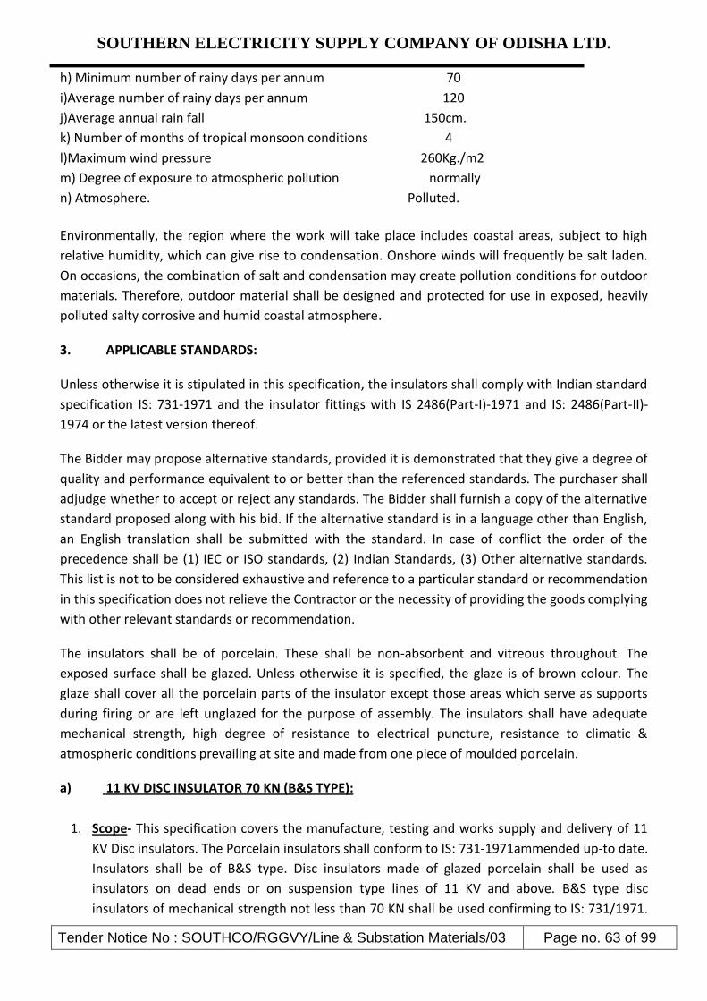
SOUTHERN ELECTRICITY SUPPLY COMPANY OF ODISHA LTD.
Tender Notice No : SOUTHCO/RGGVY/Line & Substation Materials/03 Page no. 63 of 99
h) Minimum number of rainy days per annum 70
i)Average number of rainy days per annum 120
j)Average annual rain fall 150cm.
k) Number of months of tropical monsoon conditions 4
l)Maximum wind pressure 260Kg./m2
m) Degree of exposure to atmospheric pollution normally
n) Atmosphere. Polluted.
Environmentally, the region where the work will take place includes coastal areas, subject to high
relative humidity, which can give rise to condensation. Onshore winds will frequently be salt laden.
On occasions, the combination of salt and condensation may create pollution conditions for outdoor
materials. Therefore, outdoor material shall be designed and protected for use in exposed, heavily
polluted salty corrosive and humid coastal atmosphere.
3. APPLICABLE STANDARDS:
Unless otherwise it is stipulated in this specification, the insulators shall comply with Indian standard
specification IS: 731-1971 and the insulator fittings with IS 2486(Part-I)-1971 and IS: 2486(Part-II)-
1974 or the latest version thereof.
The Bidder may propose alternative standards, provided it is demonstrated that they give a degree of
quality and performance equivalent to or better than the referenced standards. The purchaser shall
adjudge whether to accept or reject any standards. The Bidder shall furnish a copy of the alternative
standard proposed along with his bid. If the alternative standard is in a language other than English,
an English translation shall be submitted with the standard. In case of conflict the order of the
precedence shall be (1) IEC or ISO standards, (2) Indian Standards, (3) Other alternative standards.
This list is not to be considered exhaustive and reference to a particular standard or recommendation
in this specification does not relieve the Contractor or the necessity of providing the goods complying
with other relevant standards or recommendation.
The insulators shall be of porcelain. These shall be non-absorbent and vitreous throughout. The
exposed surface shall be glazed. Unless otherwise it is specified, the glaze is of brown colour. The
glaze shall cover all the porcelain parts of the insulator except those areas which serve as supports
during firing or are left unglazed for the purpose of assembly. The insulators shall have adequate
mechanical strength, high degree of resistance to electrical puncture, resistance to climatic &
atmospheric conditions prevailing at site and made from one piece of moulded porcelain.
a) 11 KV DISC INSULATOR 70 KN (B&S TYPE):
1. Scope- This specification covers the manufacture, testing and works supply and delivery of 11
KV Disc insulators. The Porcelain insulators shall conform to IS: 731-1971ammended up-to date.
Insulators shall be of B&S type. Disc insulators made of glazed porcelain shall be used as
insulators on dead ends or on suspension type lines of 11 KV and above. B&S type disc
insulators of mechanical strength not less than 70 KN shall be used confirming to IS: 731/1971.
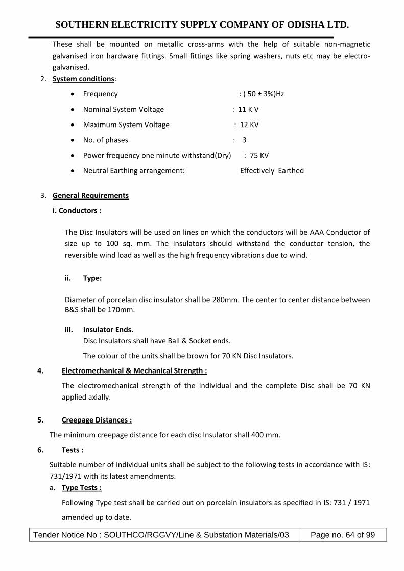
SOUTHERN ELECTRICITY SUPPLY COMPANY OF ODISHA LTD.
Tender Notice No : SOUTHCO/RGGVY/Line & Substation Materials/03 Page no. 64 of 99
These shall be mounted on metallic cross-arms with the help of suitable non-magnetic
galvanised iron hardware fittings. Small fittings like spring washers, nuts etc may be electro-
galvanised.
2. System conditions:
Frequency : ( 50 ± 3%)Hz
Nominal System Voltage : 11 K V
Maximum System Voltage : 12 KV
No. of phases : 3
Power frequency one minute withstand(Dry) : 75 KV
Neutral Earthing arrangement: Effectively Earthed
3. General Requirements
i. Conductors :
The Disc Insulators will be used on lines on which the conductors will be AAA Conductor of
size up to 100 sq. mm. The insulators should withstand the conductor tension, the
reversible wind load as well as the high frequency vibrations due to wind.
ii. Type:
Diameter of porcelain disc insulator shall be 280mm. The center to center distance between B&S shall be 170mm. iii. Insulator Ends.
Disc Insulators shall have Ball & Socket ends.
The colour of the units shall be brown for 70 KN Disc Insulators.
4. Electromechanical & Mechanical Strength :
The electromechanical strength of the individual and the complete Disc shall be 70 KN
applied axially.
5. Creepage Distances :
The minimum creepage distance for each disc Insulator shall 400 mm.
6. Tests :
Suitable number of individual units shall be subject to the following tests in accordance with IS:
731/1971 with its latest amendments.
a. Type Tests :
Following Type test shall be carried out on porcelain insulators as specified in IS: 731 / 1971
amended up to date.

SOUTHERN ELECTRICITY SUPPLY COMPANY OF ODISHA LTD.
Tender Notice No : SOUTHCO/RGGVY/Line & Substation Materials/03 Page no. 65 of 99
1. Visual Examination.
2. Verification of dimensions.
3. Visible Discharge Test.
4. Impulse voltage withstand test.
5. Impulse voltage flashover test.
6. Wet one Minute Power Frequency withstand test and West Flashover test.
7. Temperature Cycle test.
8. Electromechanical failing load test.
9. Power frequency puncture withstand test.
10. Porosity test.
11. Galvanizing test.
b. Acceptance Tests :
The test samples after having withstood the routine test shall be subject to the following acceptance
tests in order indicated below:
1. Verification of dimensions.
2. Temperature Cycle test.
3. Twenty four hour mechanical test.
4. Electromechanical failing load test.
5. Power Frequency puncture withstand test.
6. Porosity test.
7. Galvanizing test.
C. Routine Tests:
i. Visual Examination
ii. Mechanical test
iii. Electrical test
iv. Twenty four hours mechanical test
v. Electro mechanical failing load test
7. Test Certificate :
The Bidder shall furnish detailed type test reports of the offered Disc Insulators as per clause 6.
A of the Technical Specifications at the NABL approved laboratories to prove that the Disc
Insulators offered meet the requirements of the specification. These Type Tests should have
been carried out within five years prior to the date of opening of this tender.
8. Testing Facilities :
The Bidder must clearly indicate what testing facilities are available in the works of the
manufacturer and whether facilities are adequate to carry out all Routine & acceptance Tests.
These facilities should be available to Purchaser’s Engineers if deputed or carry out or witness the
tests in the manufacturer works. If any test cannot be carried out at the manufacturer's work, the

SOUTHERN ELECTRICITY SUPPLY COMPANY OF ODISHA LTD.
Tender Notice No : SOUTHCO/RGGVY/Line & Substation Materials/03 Page no. 66 of 99
reasons should be clearly stated in the tender. The insulators shall be tested in accordance with
the procedure detailed in IS-731/1971 amended up to date.
9. Mechanical Design :
The design shall be such that stresses due to expansion and contraction in any part of insulator
shall not lead to deterioration. Cement used in manufacture of the insulators shall not cause
fracture due to expansion or loosening due to contraction.
10. Drawings :
The tender shall be accompanied with the detailed drawings showing the dimensions of the
individual Disc, giving all the design dimensions of various component parts. Generally it shall
be as per IS.
11. Markings :
Each insulator shall be legibly and indelibly marked to show the following:
a) Name or trade mark of the manufacturer.
b) Voltage Type
c) Month and year of manufacturing.
d) Electromechanical strength in KN
e) Country of Manufacturer
f) ISI certificate mark
12. Packing :
All insulators shall be packed in crates or boxes suitable for rough handling. Packing shall be
marked with the strength and KV rating.
B. TECHNICAL SPECIFICATIONS OF 11 KV PIN INSULATOR
1.0 11 Kv Pin Insulators: - IS-731/77 (Porcelain Insulator for O/H power lines with nominal
voltage greater than 1000 volts.
2.0 Design and Construction
The material shall conform in all respect to the relevant Indian standards with latest amendments indicated below.
Indian Standards Title
BIS:731/1976 Porcelain insulators for overhead power lines with a nominal voltage greater than 1000V
BIS:2486 (Part-1 to Part-4) Metal fittings of insulators for overhead power lines with nominal voltage greater than 1000V
BIS:7935-1975 Porcelain insulators for overhead power lines with a nominal voltage upto and including 1000V
REC SPEC : 3/1971 11 KV Porcelain insulators and fittings
REC SPEC : 21/1981 Guy Insulator (Stay Insulator)

SOUTHERN ELECTRICITY SUPPLY COMPANY OF ODISHA LTD.
Tender Notice No : SOUTHCO/RGGVY/Line & Substation Materials/03 Page no. 67 of 99
3.0 General Requirements for 11 KV Pin Insulators
All insulators for 11KV shall conform to Type B of latest version of IS: 731. Insulator shall be as per enclosed drawing. Pin insulator shall consist of a single piece of porcelain, intended to be mounted rigidly on supporting structure by a pin, which passes up inside the insulator. The pin type insulator shall have a top groove and shall be threaded to take mild steel pins. The profile of threads shall be as per IS: 1445.
Insulators shall confirm the following specific conditions of I.S. given below
Insulator Designation Minimum Mechanical
Failing Load Minimum Creepage
Distance
11KV Pin Insulator Type B of IS:731 10KN 320mm
4.0 Tests:
The insulators shall comply with the following tests as per IS: 731-1971.
4.1 Type tests
a) Visual examination b) Verification of dimensions c) Visible discharge test d) Impulse voltage withstand test. e) Wet power-frequency voltage withstand test. f) Temperature cycle test. g) Electro-mechanical failing load test. h) Mechanical failing load test (for those of type B string insulator units to which electro
mechanical failing load test (g) is not applicable. i) Twenty four hours mechanical strength test (for string insulators only when specified
by the purchaser). j) Puncture test k) Porosity test and l) Galvanising test.
4.2 Acceptance Tests The test samples after having withstood the routine tests shall be subjected to the following
acceptance test in the order indicated below: a) Verification of dimensions. b) Temperature cycle test. c) Twenty four hours mechanical strength test(for string insulator units only when specified by
the purchaser) d) Electro-Mechanical failing load test. e) Puncture test f) Porosity test and g) Galvanising test.
4.3 Routine Test
a) Visual examination.

SOUTHERN ELECTRICITY SUPPLY COMPANY OF ODISHA LTD.
Tender Notice No : SOUTHCO/RGGVY/Line & Substation Materials/03 Page no. 68 of 99
b) Mechanical routine test(for string insulator units only) and c) Electrical routine test(for string insulator units only)
4.4 Marking 4.4.1 Each Insulator shall be legibly and indelibly marked to show the following.
a) Name and trade mark of the manufacturer. b) Month and year of manufacture c) Minimum failing load in Newtons d) Country of the manufacturer and e) ISI Certification mark,if any. f) Specific Parameters & Layout Conditions.
4.4.2 Marking on porcelain shall be printed and shall be applied before firing.
4.5 Packing
All insulators (without fittings) shall be packed in wooden crates suitable for easy but rough handling and acceptable for rail transport. Where more than one insulator are packed in a crate, wooden separators shall be fixed between the insulators to keep individual insulators in position without movement within the crate.
GURANTEED TECHNICAL PARTICULARS OF 11 KV PIN INSULATOR
Sl. No. Description Bidder’s Offer
1 Manufacturer’s name
2 Address of manufacturer
3 Location of type testing
4 Applicable standard
5 Type of insulator (Porcelain or toughened glass)
6 Dry impulse withstand voltage
7 Wet power frequency, 1 minute, withstand voltage
8 Dry, Critical Impulse Flashover Voltage
9 Dry, power frequency, Critical Flashover Voltage
10 Wet, power frequency, Critical Flashover Voltage
11 Power frequency Puncture Voltage
12 Safe Working Load
13 Minimum Failing Load
14 Creepage Distance
15 Protected Creepage Distance
16 Type and Grade of Materials : Insulator
17 Type and Grade of Materials : Thimble
18 Type and Grade of Materials : Cement
19 Type of semi conducting Glaze
20 Radius of Conductor Groove
21 Colour of Insulator

SOUTHERN ELECTRICITY SUPPLY COMPANY OF ODISHA LTD.
Tender Notice No : SOUTHCO/RGGVY/Line & Substation Materials/03 Page no. 69 of 99
22 Weight of Insulator
23 Number of Insulators per Crate
24 Gross Weight of Loaded Crate
25
Whether drawing showing dimensional details have been furnished along with Bid
26 Whether Type Test Certificates have been furnished
27 Other particulars (if any)
c) L.T. Shackle Insulator : – Confirming to IS : 1445 / 1977 with latest amendments.
GROUP – F 11 KV H.W. Fittings ( B & S Type) ( 70 KN ) The Tension Hard Ware Fittings are to be suitable for the AAA Conductor sizes up to 55 mm2 as
per IS : 2486 / Part – I – 1993 , Part – II – 1989 & Part – IV – 1981 and their latest amendments , if
any with minimum failing load of Hard Ware not less than the permissible limit of Breaking load /
Ultimate tensile strength for particular conductor as per IS. This should be bolted type having
minimum 3 Nos of “U “bolts & provided with a suitable tongue. The minimum failing load will be
not less than 70 KN.
N.B. : - For all types of H.W. Fittings
1. Galvanization: - All ferrous parts should be galvanized as per IS - 2633 / 1972 or it’s latest
amendments if any & all non-ferrous part should be duly electroplated with silver.
2. Type Test Certificate: - The Type Test Certificate, conducted within five years before the date
of opening of tender from Govt. Testing Laboratory (NABL accredited) // CPRI shall be submitted.
The Certificate from a Testing Laboratory (NABL accredited) regarding composition of copper
in electrolytic copper casting and galvanization as per ISS is to be furnished during inspection of
materials.
3. Drawing: - To be furnished by Bidder. The details of construction and materials of different
parts shall clearly be indicated in the drawing and illustrative pamphlet // literature for the same
shall be submitted along with the tender.

SOUTHERN ELECTRICITY SUPPLY COMPANY OF ODISHA LTD.
Tender Notice No : SOUTHCO/RGGVY/Line & Substation Materials/03 Page no. 70 of 99
Group - G
TECHNICAL SPECIFICATION OF 11KV G.I.PIN
1.0 11 KV GI Pin: - Confirming to IS-2486 Part-I/1971.
a) The pins shall be of single piece obtained by the process of forging. They will not be
made by any process using more than one piece of material. The pin will have good finish, free from flaws and other defects. The finish of the collar shall be such that a sharp angle between the collar and the shank is avoided. All ferrous pins, nuts and washers, except those made of stainless steel shall be galvanized by hot dip process. Other fittings, i.e flat washers and spring washers may be electro-galvanized as per IS: 2486. The threads of nuts, and toped holes, when cut after galvanization shall be well oiled or greased.
b) The pins shall be as per relevant figure indicated in IS 2486 (part II) having stalk length of 165 mm and shank length of 150 mm with minimum failing load of 10 KN with large heads and shall match with the pin type insulators with cemented zinc thimble having similar threads.
1.0 TESTS:
The pins shall be tested as per IS: 2486 (part-1):1993 1.1 Type Test:
The bidder has to enclose the reports of the following type tests carried out in any govt. recognized laboratory along with the bid documents. a) Checking of Threads on Heads b) Galvanizing Test c) Visual Examination d) Mechanical Test.
1.2 Acceptance Tests: Following tests shall be carried out at the works of the manufacturer before dispatch.
a) Checking of Threads on Heads
b) Galvanizing Test
c) Visual Examination
d) Mechanical Test.

SOUTHERN ELECTRICITY SUPPLY COMPANY OF ODISHA LTD.
Tender Notice No : SOUTHCO/RGGVY/Line & Substation Materials/03 Page no. 71 of 99
GURANTEED TECHNICAL PARTICULARS
Group –H A) 11 KV “V” Cross Arm
The cross arm is to be made out of I.S.M.C., M.S. Channel 75 x 40 mm ( as per IS : 2062 , 808 , &
12779 ) ( Sp. Wt. 6.8 Kg / Mtr ) with both side flat packing at GI Pin points with two Coats of Red
Oxide Painting ( Approximate Weight of 10.0 Kg Each , with tolerance on Sp. weight per meter
shall be + / - 4 % for steel ). Others as per REC - Construction Standard and as per enclosed
drawing.
B ) L.T. Cross Arm ( 2 Ph 3 W )
The cross arm is to be made out of I.S.M.C., M.S. Channel 75 x 40 mm ( as per IS : 2062 , 808 &
12779 ) ( Sp. Wt. 6.8 Kg / Mtr ) as per REC - Construction Standard B - 3 , Page - 41 ( Approx.
Weight being 5.50 Kg / Each , with tolerance on Sp. weight per meter shall be + / - 4 % for steel ).
Sl. No. General Technical Particulars Bidder’s Offer
1. Manufacturer’s name & Address
2. Standard applicable specification
3. Minimum failing load
4. Dimensions (mm)
a Total length
b Shank length
c Stalk length
5. Type of threads
6. Threads per Inch
7. Type of galvanization of pin & nuts
8. Mass of zinc (minimum)
9. Applicable specification
10. No. of Nuts with each pin & its size
11. No. of spring washer with each pin & its size
12. Packing details
a Type of packing
b Weight of each pin approx, (with nut & washers)
c No. of Pins in each packing (Kg)
13. Tolerance in weight / dimensions, if any
14. I.S.I. Certificate License number
15. Any other relevant information the bidder would like to indicate
16. Manufacturer’s Trade mark with each GS Pins
17. Whether drawing has been submitted by the bidder

SOUTHERN ELECTRICITY SUPPLY COMPANY OF ODISHA LTD.
Tender Notice No : SOUTHCO/RGGVY/Line & Substation Materials/03 Page no. 72 of 99
Group –I
GUARANTED TECHNICAL PARTICULARS OF HT & LT STAY SET
H.T. Stay Set: – (A) The Stay set is to consist of G.S. stay rod of 20 mm dia , 1800 mm in length ,
one side formed an eye & welded with internal dia 40 mm with one thimble & the other side of
the rod is threaded & fitted with 2 nos of suitable hexagonal nuts & with one round washer of 3
mm thickness , complete with G.S. anchor plate 250 x 250 x 6 mm dimensions with centre hole of
22 mm dia. The entire rod , plate , thimble, nuts & washer should be hot dipped galvanized as per
IS : 2633 – 1972 with latest amendments.
(B) Single Bow turn buckle made of 16 mm dia G.S. rod & the centre rod of 20 mm dia length 450
mm with one end formed an eye & welded. The threaded length of the centre rod should be of
300 mm. The base channel of the bow of size 75 x 40 x 6 mm & 180 mm in length with thimble & 2
Nos suitable G.I. Hexagonal nuts of suitable size conforming toIS:1363:1967 & IS:1367:1967. The
items should be hot dipped galvanized as per IS : 2633 / 1972 with latest amendments.
2) L.T. Stay Set : – (A) The Stay set is to consist of Stay Rod , Anchor Plate , Single bow turn buckle
made of G.S. stay rod of 16 mm dia ,1800 mm in length , with one thimble & the other side of the
rod is threaded & fitted with 2 nos of suitable hexagonal nuts & with one round washer of 3 mm
thickness , complete with G.S. anchor plate 150 x 150 x 6 mm dimensions with centre hole of 18
mm dia. The entire rod, plate, thimble, nuts & washer should be hot dipped galvanized as per IS :
2633 – 1972 with latest amendments.
(B) Single Bow turn buckle made of 16 mm dia G.S. rod & the center rod of 20 mm dia of length
450 mm with one end formed an eye & welded. The threaded length of the center rod should be of
300 mm. The base channel of the bow of size 50 x 50 x 6 mm & 180 mm in length with thimble & 2
Nos suitable G.I. Hexagonal nuts of suitable size conforming to IS:1363:1967 & IS:1367:1967. The
items should be hot dipped galvanized as per IS : 2633 / 1972 with latest amendments.
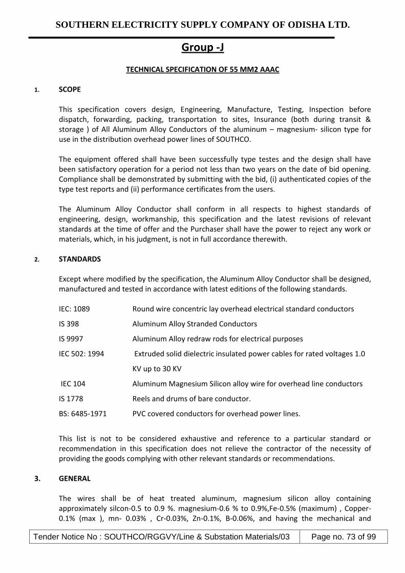
SOUTHERN ELECTRICITY SUPPLY COMPANY OF ODISHA LTD.
Tender Notice No : SOUTHCO/RGGVY/Line & Substation Materials/03 Page no. 73 of 99
Group -J
TECHNICAL SPECIFICATION OF 55 MM2 AAAC 1. SCOPE
This specification covers design, Engineering, Manufacture, Testing, Inspection before dispatch, forwarding, packing, transportation to sites, Insurance (both during transit & storage ) of All Aluminum Alloy Conductors of the aluminum – magnesium- silicon type for use in the distribution overhead power lines of SOUTHCO. The equipment offered shall have been successfully type testes and the design shall have been satisfactory operation for a period not less than two years on the date of bid opening. Compliance shall be demonstrated by submitting with the bid, (i) authenticated copies of the type test reports and (ii) performance certificates from the users. The Aluminum Alloy Conductor shall conform in all respects to highest standards of engineering, design, workmanship, this specification and the latest revisions of relevant standards at the time of offer and the Purchaser shall have the power to reject any work or materials, which, in his judgment, is not in full accordance therewith.
2. STANDARDS Except where modified by the specification, the Aluminum Alloy Conductor shall be designed, manufactured and tested in accordance with latest editions of the following standards.
IEC: 1089 Round wire concentric lay overhead electrical standard conductors
IS 398 Aluminum Alloy Stranded Conductors
IS 9997 Aluminum Alloy redraw rods for electrical purposes
IEC 502: 1994 Extruded solid dielectric insulated power cables for rated voltages 1.0
KV up to 30 KV
IEC 104 Aluminum Magnesium Silicon alloy wire for overhead line conductors
IS 1778 Reels and drums of bare conductor.
BS: 6485-1971 PVC covered conductors for overhead power lines.
This list is not to be considered exhaustive and reference to a particular standard or recommendation in this specification does not relieve the contractor of the necessity of providing the goods complying with other relevant standards or recommendations.
3. GENERAL The wires shall be of heat treated aluminum, magnesium silicon alloy containing approximately silcon-0.5 to 0.9 %. magnesium-0.6 % to 0.9%,Fe-0.5% (maximum) , Copper- 0.1% (max ), mn- 0.03% , Cr-0.03%, Zn-0.1%, B-0.06%, and having the mechanical and

SOUTHERN ELECTRICITY SUPPLY COMPANY OF ODISHA LTD.
Tender Notice No : SOUTHCO/RGGVY/Line & Substation Materials/03 Page no. 74 of 99
electrical properties specified in the table and be smooth and free from all imperfections, such as, spills, splits and scratches. Neutral grease shall be applied between the layers of wires. The drop point temperature of the grease shall not be less than 120 0C.
3.1 Mechanical and Electrical Characteristics of Aluminum Alloy Wires used in the Construction of Stranded Aluminum Alloy Conductors
Nominal Diameter
Minimum Diameter
Max. Diameter
Cross Sectional
Area
Mass Minimum Breaking Load
Maximum Resistance
at 200C
Before stranding
After stranding
1 2 3 4 5 6 7 8
mm mm mm mm2 Kg/km KN KN ohms/ km
3.15 3.12 3.18 7.793 21.04 2.37 2.29 4.290
Maximum resistance values given in column 8 have been calculated from the maximum values of the resistively as specified and the cross sectional area based on the minimum diameter. The minimum breaking load is calculated on nominal diameter at ultimate tensile strength of 0.309 KN / mm2 for wire before stranding and 95% of the ultimate tensile strength after stranding.
4. PHYSICAL CONSTANTS FOR ALUMINIUM ALLOY WIRES
4.1 Resistively : For the purpose of this specification, the standard value of resistively of aluminum alloy wire which shall be used for calculation is to be taken as 0.0325 ohm mm2 /m at 200 C. The maximum value of resistively of any single wire shall not , however, exceed 0.0328 ohm. mm2/m at 200 C
4.2 Density : At a temperature of 200 C, the density of aluminum alloy wire is to be taken as 2700 kg/m3.
4.3 Temperature Coefficient of Linear Expansion: The temperature coefficient of linear expansion of aluminium alloy wire is to be taken as 23 x 10 –6 / 0 C
4.4 Constant – Mass Temperature Coefficient At a Temperature of 200 C, the constant – mass temperature coefficient of resistance of aluminum alloy wires, measured between two potential points rigidly fixed to the wire, is taken as 0.00360/0 C

SOUTHERN ELECTRICITY SUPPLY COMPANY OF ODISHA LTD.
Tender Notice No : SOUTHCO/RGGVY/Line & Substation Materials/03 Page no. 75 of 99
5. STANDARD SIZES
5.1 Nominal Sizes of Wires
The aluminum alloy wires for standard constructions covered by this specification shall have the diameters as specified in the table and a tolerance of ±1% shall be permitted on the nominal diameter.
5.2 Standard Conductors The sizes, resistance and masses (excluding the mass of grease) of stranded aluminum alloy conductors shall be as given in table.
5.3 Mechanical and Electrical Characteristics of Aluminum Alloy Stranded
Sl. No. Actual Area
Stranding and Wire
Dia
Approx. Overall
Dia
Approx. Mass
Calculated Maximum Resistance
at 200 C
Approx Calculated Breaking
Load
1 2 3 4 5 6 7
mm2 mm mm kg/km ohms/km KN
1 55 7/3.15 9.45 149.20 0.621 16.044
5.3.1 Increase in Length due to Stranding
When straightened out, each wire in any particular layer of a stranded conductor, except the central wire, is longer than the stranded conductor by an amount depending on the lay ratio of that layer.
5.3.2 Resistance and Mass of Conductor The resistance of any length of stranded conductor is the resistance of the same length of any one wire multiplied by a constant as set out in the table below. The mass of each wire in any particular layer of the stranded conductor, except the central wire, will be greater than that of an equal length of straight wire by an amount depending on the lay ratio of that layer. The total mass of any length of an aluminum stranded conductor is, therefore, obtained by multiplying the mass of an equal length of straight wire by an appropriate constant as mentioned below. In calculating the stranding constants as mentioned in the table below, the mean lay ratio, that is the arithmetic mean of the relevant minimum and maximum values in table for lay ratio has been assumed for each layer.
5.3.3 Calculated Breaking Load of Conductor For a conductor containing not more than 37 wires, 95% of the sum of strength of the individual wires calculated from the values of the minimum breaking load given in this specification.
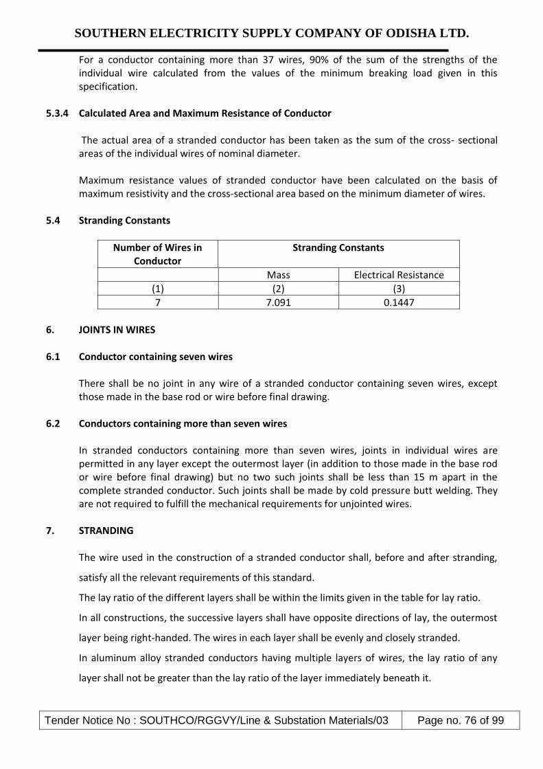
SOUTHERN ELECTRICITY SUPPLY COMPANY OF ODISHA LTD.
Tender Notice No : SOUTHCO/RGGVY/Line & Substation Materials/03 Page no. 76 of 99
For a conductor containing more than 37 wires, 90% of the sum of the strengths of the individual wire calculated from the values of the minimum breaking load given in this specification.
5.3.4 Calculated Area and Maximum Resistance of Conductor The actual area of a stranded conductor has been taken as the sum of the cross- sectional areas of the individual wires of nominal diameter. Maximum resistance values of stranded conductor have been calculated on the basis of maximum resistivity and the cross-sectional area based on the minimum diameter of wires.
5.4 Stranding Constants
Number of Wires in Conductor
Stranding Constants
Mass Electrical Resistance
(1) (2) (3)
7 7.091 0.1447
6. JOINTS IN WIRES
6.1 Conductor containing seven wires
There shall be no joint in any wire of a stranded conductor containing seven wires, except those made in the base rod or wire before final drawing.
6.2 Conductors containing more than seven wires In stranded conductors containing more than seven wires, joints in individual wires are permitted in any layer except the outermost layer (in addition to those made in the base rod or wire before final drawing) but no two such joints shall be less than 15 m apart in the complete stranded conductor. Such joints shall be made by cold pressure butt welding. They are not required to fulfill the mechanical requirements for unjointed wires.
7. STRANDING The wire used in the construction of a stranded conductor shall, before and after stranding,
satisfy all the relevant requirements of this standard.
The lay ratio of the different layers shall be within the limits given in the table for lay ratio.
In all constructions, the successive layers shall have opposite directions of lay, the outermost
layer being right-handed. The wires in each layer shall be evenly and closely stranded.
In aluminum alloy stranded conductors having multiple layers of wires, the lay ratio of any
layer shall not be greater than the lay ratio of the layer immediately beneath it.

SOUTHERN ELECTRICITY SUPPLY COMPANY OF ODISHA LTD.
Tender Notice No : SOUTHCO/RGGVY/Line & Substation Materials/03 Page no. 77 of 99
7.1 Lay Ratios for Aluminum Alloy Stranded Conductors
Number of Wires in Conductor
LAY RATIOS
3/6 Wire Layer 12 Wire Layer
Min Max Min Max
7 10 14 --- ---
NOTE: For the purpose of calculation the mean lay ratio shall be taken as the arithmetic mean of the relevant minimum and maximum values given in this table.
8. LENGTHS AND VARIATIONS IN LENGTHS: Unless otherwise agreed between the Purchaser and the Supplier, stranded aluminum alloy conductors shall be supplied in the manufacturer’s usual production lengths to be indicated in the bid Schedule. The Employer reserves the right to specify particular lengths of conductor such that certain drum lengths will be shorter than others. There will in both cases be a permitted variation of –0 + 5% in the length of any one conductor length.
9. TESTS
9.1 Type Tests The following tests should have been carried out as per relevant ISS on samples of completed line conductor:
1) Ultimate Tensile Strength Test 2) D.C Resistance Test
9.2 Routine Tests
Measurement of Physical Dimensions: The samples should meet the desired dimensional requirements before conducting following Routine Tests as per relevant ISS.
9.2.1 Selection of Test Samples Samples shall be obtained by cutting 1.2 meters from the outer end of the finished conductor from not more than 10% of the finished reels or drums. Tests for electrical and mechanical properties of aluminum alloy wire shall ordinarily be made before stranding since wires unlaid from conductors may have different physical properties from those of the wire prior to stranding because of the deformation brought about by stranding and by straightening for test. Spools offered for inspection shall be divided into equal lots, the number of lots being equal to the number of samples to be selected, a fraction of a lot being counted as a complete lot. One sample spool shall be selected at random from each lot.

SOUTHERN ELECTRICITY SUPPLY COMPANY OF ODISHA LTD.
Tender Notice No : SOUTHCO/RGGVY/Line & Substation Materials/03 Page no. 78 of 99
The following test shall be carried out once on samples of completed line conductor during each production run of up to 500 kms of the conductor from each manufacturing facility.
9.2.2 Breaking Load Test The breaking load of one specimen, cut from each of the samples taken shall be determined by means of a suitable tensile testing machine. The load shall be applied gradually and the rate of separation of the jaws of the testing machine shall be not less than 25 mm / min and not greater than 100mm /min.
9.2.3 Elongation Test The elongation of one specimen cut from each of the samples taken shall be determined as follows: The specimen shall be straightened by hand and an original gauge length of 200 mm shall be marked on the wire. A tensile load shall be applied as described above and the elongation shall be measured after the fractured ends have been fitted together. If the fracture occurs outside the gauge marks, or within 25 mm of eithermark, and the required elongation is not obtained, the test shall be disregarded and another test should be made. When tested before and after stranding, the elongation shall not be less than 4% on a gauge length of 200 mm.
9.2.4 D.C Resistance Test The electrical resistance test of one specimen cut from each of the samples taken shall be measured at ambient temperature. The measured resistance shall be corrected to the value at 200 C by means of the formula :
R20 = RT {-----------1---------------- }
1 + α(T-20) where , R20 = resistance corrected at 200 C
RT = resistance measured T0C α = constant – mass temperature coefficient of resistance, 0.0036,
and T = ambient temperature during measurement.
The resistance corrected at 200 C shall not be more than the maximum values specified.
9.2.5 Chemical Analysis of Aluminum Alloy
Samples taken from the alloy coils / strands shall be chemically / spectrographically analyzed. The results shall conform to the requirements stated in this specification. The contractor shall

SOUTHERN ELECTRICITY SUPPLY COMPANY OF ODISHA LTD.
Tender Notice No : SOUTHCO/RGGVY/Line & Substation Materials/03 Page no. 79 of 99
make available material analyses, control documents and certificates from each batch as and when required by the Purchaser.
Test should be conducted at the independent test house by the purchaser in the case of absence of facility at manufacturer. However the cost of such testing shall be borne by the manufacturer.
9.2.6 Dimensional and Lay Length Check
The individual strands of the conductors shall be dimensionally checked and the lay lengths checked to ensure that they conform to the requirements of this specification.
Ten percent drums from each lot shall be rewound in the presence of the Purchaser or his representative to allow visual checking of the conductor for joints, scratches or other surface imperfections and to ensure that the conductor generally conforms to the requirements this specification. The length of conductor wound on the drum shall be re-measured by means of an approved counter / meter during the rewinding process.
9.2.7 Visual and dimensional Checks on the Conductor Drums.
The drums shall be visually and dimensionally checked to ensure that they conform to the requirements of this specification and of IS 1778: Specification for reels and drums of bare conductors. For wooden drums, a suitable barrel batten strength test procedure is required. The Bidder shall state in his bid the tests to be carried out on the drums and shall include those tests in the Quality Assurance Programme.
9.2.8 Acceptance Tests:
All tests required to confirm an enclosed Guaranteed Technical Particulars (GTP) requirement of this specification needs to be conducted as Acceptance Tests.
10. Packing.
a) The conductor shall be supplied in returnable, strong, wooden drums provided with
lagging of adequate strength, constructed to protect the conductor against any damage and displacement during transit, storage and subsequent handling and stringing operations in the field. The Contractor shall be responsible for any loss or damage during transportation handling and storage due to improper packing. The drums shall generally conform to IS: 1778-1980, except as otherwise specified hereinafter.
b) The drums shall be suitable for wheel mounting and for letting off the conductor under a minimum controlled tension of the order of 5 KN.
c) The Contractor should submit their proposed drum drawings along with the bid. d) The Contractor may offer more than one length of the conductor in a single drum. e) All wooden components shall be manufactured out of seasoned soft wood free from
defects that may materially weaken the component parts of the drums. Preservative treatment shall be applied to the entire drum with preservatives of a quality, which is not harmful to the conductor.

SOUTHERN ELECTRICITY SUPPLY COMPANY OF ODISHA LTD.
Tender Notice No : SOUTHCO/RGGVY/Line & Substation Materials/03 Page no. 80 of 99
f) The flanges shall be of two ply construction with a total thickness of 64 mm with each ply at right angles to the adjacent ply and nailed together. The nails shall be driven from the inside face flange, punched and then clenched on the outer face. Flange boards shall not be less than the nominal thickness by more than 2mm. There shall not be less than 2 nails per board in each circle. Where a slot is cut in the flange to receive the inner end of the conductor the entrance shall be in line with the periphery of the barrel.
g) The wooden battens used for making the barrel of the conductor shall be of segmental type. These shall be nailed to the barrel supports with at least two nails. The batten shall be closely butted and shall provide a round barrel with smooth external surface. The edges of the battens shall be rounded or chamfered to avoid damage to the conductor.
h) Barrel studs shall be used for the construction of drums. The flanges shall be holed and the barrel supports slotted to receive them. The barrel studs shall be treaded over a length on either end, sufficient to accommodate washers, spindle plates and nuts for fixing flanges at the required spacing.
i) Normally, the nuts on the studs shall stand protruded of the flanges. All the nails used on the inner surface of the flanges and the drum barrel shall be counter sunk. The ends of barrel shall generally be flushed with the top of the nuts.
j) The inner cheek of the flanges and drum barrel surface shall be painted with bitumen based paint.
k) Before reeling, card board or double corrugated or thick bituminous water proof bamboo paper shall be secured to the drum barrel and inside of flanges of the drum by means of a suitable commercial adhesive material. The paper should be dried before use. After reeling the conductor, the exposed surface of the outer layer of conductor shall be wrapped with water proof thick bituminous bamboo paper to preserve the conductor from dirt, grit and damage during transport and handling.
l) A minimum space of 75 mm for conductor shall be provided between the inner surface of the external protective lagging and outer layer of the conductor. Outside the protective lagging, there shall be minimum of two binders consisting of hoop iron/galvanized steel wire. Each protective lagging shall have tow recesses to accommodate the binders.
m) Each batten shall be securely nailed across grains as far as possible to the flange, edges with at least 2 nails per end. The length of the nails shall not be less than twice the thickness of the battens. The nails shall not protrude above the general surface and shall not have exposes sharp, edges or allow the battens to be released due to corrosion.
n) The nuts on the barrel studs shall be tack welded on the one side in order to fully secure them. On the second end, a spring washer shall be used.
o) A steel collar shall be sued to secure all barrel studs. This collar shall be located between the washers and the steel drum and secured to the central steel plate by welding.
p) Outside the protective lagging, there shall be minimum of two binders consisting of hoop iron/ galvanized steel wire. Each protective lagging shall have two recesses to accommodate the binders.
q) The conductor ends shall be property sealed and secured with the help of U-nail on the side of one of the flanges to avoid loosening of the conductor layers during transit and handling.

SOUTHERN ELECTRICITY SUPPLY COMPANY OF ODISHA LTD.
Tender Notice No : SOUTHCO/RGGVY/Line & Substation Materials/03 Page no. 81 of 99
r) As an alternative to wooden drum Contractor may also supply the conductors in non- returnable painted steel drums. After preparation of steel surface according to IS: 9954, synthetic enamel paint shall be applied after application of one coat of primer. Wooden/Steel drum will be treated at par for evaluation purpose and accordingly the Contractor should quote in the package.
11.0 Marking.
Each drum shall have the following information stenciled on it in indelible ink along with other essential data:
(a) Contract/Award letter number (b) Name and address of consignee. (c) Manufacture’s name and address. (d) Drum and lot number (e) Size and type of conductor (f) Length of conductor in meters (g) Arrow marking for unwinding (h) Position of the conductor ends (i) Number of turns in the outer most layer. (j) Gross weight of the drum after putting lagging. (k) Average weight of the drum without lagging. (l) Net weight of the conductor in the drum (m) Month and year of manufacture of conductor The above should be indicated in the packing list also.
12.0 Verification Conductor Length
The Owner reserves the right to verify the length of conductor after unreeling at least five (5) percent of the drums in a lot offered for inspection. For the balance drums, length verification shall be done by the owner based on report/certification from Manufacturer/ Contractor.
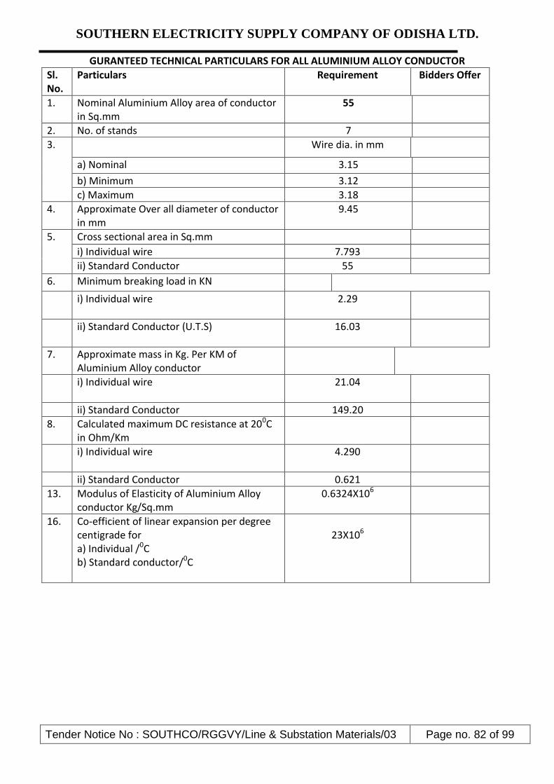
SOUTHERN ELECTRICITY SUPPLY COMPANY OF ODISHA LTD.
Tender Notice No : SOUTHCO/RGGVY/Line & Substation Materials/03 Page no. 82 of 99
GURANTEED TECHNICAL PARTICULARS FOR ALL ALUMINIUM ALLOY CONDUCTOR
Sl. No.
Particulars Requirement Bidders Offer
1. Nominal Aluminium Alloy area of conductor in Sq.mm
55
2. No. of stands 7
3. Wire dia. in mm
a) Nominal 3.15
b) Minimum 3.12
c) Maximum 3.18
4. Approximate Over all diameter of conductor in mm
9.45
5.
Cross sectional area in Sq.mm
i) Individual wire 7.793
ii) Standard Conductor 55
6. Minimum breaking load in KN
i) Individual wire 2.29
ii) Standard Conductor (U.T.S) 16.03
7. Approximate mass in Kg. Per KM of Aluminium Alloy conductor
i) Individual wire 21.04
ii) Standard Conductor 149.20
8. Calculated maximum DC resistance at 200C in Ohm/Km
i) Individual wire 4.290
ii) Standard Conductor 0.621
13. Modulus of Elasticity of Aluminium Alloy conductor Kg/Sq.mm
0.6324X10⁶
16. Co-efficient of linear expansion per degree centigrade for a) Individual /0C b) Standard conductor/0C
23X106

SOUTHERN ELECTRICITY SUPPLY COMPANY OF ODISHA LTD.
Tender Notice No : SOUTHCO/RGGVY/Line & Substation Materials/03 Page no. 83 of 99
Group - K
TECHNICAL SPECIFICATION OF 7/10 & 7/12 SWG GI STAY WIRE
1.0 Application Standards
Except when they conflict with the specific requirements of this specification, the G.I Stay Stranded Wires shall comply with the specific requirements of IS: 2141-1979. IS: 4826-1979 & IS: 6594-1974 or the latest versions thereof.
2.0 Application and Sizes
a) The G.I. stranded wires covered in this Specification are intended for use on the overhead power line poles, distribution transformer structures etc.
b) The G.I stranded wires shall be of 7/10SWG (7/3.15 mm for 11KV lines and 7/12 SWG
7/2.5 mm for LT lines standard sizes. 3.0 Materials
The wires shall be drawn from steel made by the open hearth basic oxygen or electric furnace process and of such quality that when drawn to the size of wire specified and coated with zinc, the finished strand and the individual wires shall be of uniform quality and have the properties and characteristics as specified in this specification. The wires shall not contain sulphur and phosphorus exceeding 0.060% each.
3.1 Tensile Grade
The wires shall be of tensile grade 4, having minimum tensile strength of700 N/mm² conforming to 1S:2141.
3.2 General Requirements
a) The outer wire of strands shall have a right-hand lay. b) The lay length of wire strands shall be 12 to 18 times the strand diameter.
3.3 Minimum Breaking Load
The minimum breaking load of the wires before and after stranding shall be as follows:
No. of Wires & Const.
Wire Dia (mm)
Min. breaking load of the Single wire before stranding
(KN)
Min. breaking load of the standard
wire (KN) 7 (6/1) 2.5 3.44 21.40 7 (6/1) 3.15 5.46 34.00
7 (6/1) 4.0 8.80 54.9
4.0 Construction

SOUTHERN ELECTRICITY SUPPLY COMPANY OF ODISHA LTD.
Tender Notice No : SOUTHCO/RGGVY/Line & Substation Materials/03 Page no. 84 of 99
a) The galvanized stay wire shall be of 7-wire construction. The wires shall be so stranded together that when an evenly distributed pull is applied at the ends of completed strand, each wire shall take an equal share of the pull.
b) Joints are permitted in the individual wires during stranding but such joints shall not be
less than 15 metres apart in the finished strands.
c) The wire shall be circular and free from scale, irregularities, imperfection, flaws, splits and other defects.
5.0 Tolerances
A tolerance of (+) 2.5% on the diameter of wires before stranding shall be permitted.
6.0 Sampling Criteria
The sampling criteria shall be in accordance with IS: 2141.
7.0 Tests on Wires before Manufacture
7.1 The wires shall be subjected to the following tests in accordance with IS: 2141.
a) Ductility Test b) Tolerance on Wire Diameter
7.2 Tests on Completed Strand
The completed strand shall be tested for the following tests in accordance with IS: 2141.
a) Tensile and Elongation Test: The percentage elongation of the stranded wire shall not be less than 6%.
b) Chemical analysis c) Galvanizing Test
The Zinc Coating shall conform to "Heavy Coating" as laid down in 1S:4826 8.0 Marking
Each coil shall carry a metallic tag, securely attached to the inner part of the coil bearing the following information: a) Manufacturers name or trade mark
b) Lot number and coil number
c) Size
d) Construction
e) Tensile Designation
f) Lay
g) Coating

SOUTHERN ELECTRICITY SUPPLY COMPANY OF ODISHA LTD.
Tender Notice No : SOUTHCO/RGGVY/Line & Substation Materials/03 Page no. 85 of 99
h) Length
i) Mass
j) ISI certification mark, if any
9.0 Packing
The wires shall be supplied in 75-100 Kg. coils. The packing should be done in accordance with the provisions of IS:6594
10.0 Other Items:
For remaining items of stay sets mentioned in the enclosed drawing, relevant applicable Indian standards shall be applicable.
Group -L
Technical Specification of LT G.I. Straps with N&B
LT GI Shackle Straps ( 200 X 40 X 5 mm ) with 115 X 12 mm Hexagonal Bolts , Nuts & Washers
comply with REC Specification & IS:7935-1975 or the latest versions thereof.
GROUP – M: EARHTING COIL
TECHNICAL SPECIFICATION
1.0 SCOPE
The specification covers design, manufacture, testing and dispatch to the owner’s stores of Earthing Coils for use in earthing of the HT & LT poles.
2.0 GENERAL REQUIREMENTS
Earthing coils shall be fabricated from soft GI Wire Hot Dip Galvanized. The Hot Dip galvanized wire shall have clean surface and shall be free from paint enamel or any other poor conducting material. The coil shall be made as per REC constructions standard.
The Hot Dip galvanizing shall conform to IS: 2629/1966, 2633/1972 and 4826/1969 with latest amendments.
3.0 TESTS 3.1 Galvanizing Tests
Minimum Mass of Zinc

SOUTHERN ELECTRICITY SUPPLY COMPANY OF ODISHA LTD.
Tender Notice No : SOUTHCO/RGGVY/Line & Substation Materials/03 Page no. 86 of 99
ON GI Wire used 280 cm/m² After Coiling-266 gm/m².The certificate from recognized laboratory shall be submitted
towards mas of zinc. 3.2 Dip Test
Dip test shall stand 3 dips of 1 minute and one dip of ½ minute before coiling and 43 dips of 1 minute after coiling as per IS: 4826/1979
3.3 Adhesion Test
As per ISS 4826 – 1979. 4.0 DIMENSIONAL REQUIREMENT
a) Nominal dia of GI Wire4 mm (Tolerance±2.5%)
b) Minimum no. of turns – 115 Nos.
c) External dia of Coil (Min) – 50 mm
d) Length of Coil (Min) – 460 mm
e) Free length of GI Wire at one end coil (Min.) – 2500 mm
The turns should be closely bound. Weight of one finished Earthing Coils (min.) – 1.850 Kg.
GUARANTEED TECHNICAL PARTICULARS
Sl.
No. GENERAL TECHNICAL PARTICULARS Bidder’s Offer
1 Nominal diameter of wire
2 No. of turns
3 External dia of Coil
4 Length of Coil
5 Mass of Zinc
6 Total weight of Coil
7 Whether drawing enclosed (yes)
Group – N
GUARANTEED TECHNICAL PARTICULARS of MS CHANNEL & ANGLE
1.00 SCOPE This specification covers design, manufacture, testing and dispatch to owner’s stores of M.S. Channel & Angle for use in structures in distribution system.

SOUTHERN ELECTRICITY SUPPLY COMPANY OF ODISHA LTD.
Tender Notice No : SOUTHCO/RGGVY/Line & Substation Materials/03 Page no. 87 of 99
2.00 APPLICABLE STANDARD
Materials shall conform to the latest applicable Indian standards. In case bidders offer steel section and supports conforming to any other international specifications which shall be equivalent or better than IS, the same is also acceptable. Sl.No. Standard No. Title 1 IS: 2062 Grade ‘A’Quality Specification for M.S.Angles, M.S.Channel 2 IS: 2062 Chemical and Physical composition of material 3 IS: 1852 Rolling and Cutting Tolerances for Hot Rolled Steel products
3.00 3.01 3.02 3.03 3.04 3.05 3.06
GENERAL REQUIREMENTS Raw material The Steel Sections shall be manufactured from the BILLETS/INGOTS only of tested quality as per latest version of IS: 2830 or to any equivalent International Standard and shall be arranged by the bidder from their own sources. The Chemical composition and Physical properties of the finished material shall be as per the equivalent standards. Length The steel sections to be supplied shall be in 5.5 meters length. Weightment The weighnment of steel sections shall be witnessed by the consignee at the time of taking delivery. The weight recorded in the material receipt certificate issued by the consignees shall be final. Chemical Composition and Physical Properties of M.S. Angles, M.S. Channels, and M.S.Flat conforming to IS: Conforming to IS:2062/84 Chemical Composition Chemical composition For Fe 410 WA Grade 1 C - 0.23% MAX 2 Mn - 1.5% MAX 3 S - 0.050% MAX 4 P - 0.050% MAX 5 SI - 0.40% MAX 6 CE (Carbon Equivalent)- 0.42% MAX Mechanical Properties

SOUTHERN ELECTRICITY SUPPLY COMPANY OF ODISHA LTD.
Tender Notice No : SOUTHCO/RGGVY/Line & Substation Materials/03 Page no. 88 of 99
3.07
1. Tensile strength Kgf/mm²‾ - 410 2. Yield stress Min. for thickness/diameter < 20 mm - 26 Kgf/mm² OR 250 N/ mm² 20-40 mm - 24 Kgf/mm² OR 240 N/ mm² > 40 mm - 23 Kgf/mm² OR 230 N/ mm² 3. Elongation % - 23% 4. Bend Test (Internal Dia) - Min-3ţ (t – is the thickness of the material) Tolerance Variation in ordered quantity for any destination and overall ordered quantity shall be only to the extent of ±2%. Rolling and weight tolerances shall be as per version of IS: 1852 or to any equivalent International Standard.
4.00 TEST Steel Section shall be tested in IS approved Laboratory or Standard Laboratory the Bidder country having all facilities available for conducting all the test prescribed in relevant IS or IEC or to any equivalent International Standard or any recognized and reputable International Laboratory or Institutions. The bidders are required to specifically indicate that;
i) They hold valid IS (or equivalent IEC) License. ii) Steel Section offered are bearing requisite IS certification or equivalent marks.
The bidders are required to submit a copy of the valid IS (or equivalent IEC) License clearly indicating size and range of product against respective ISS or any equivalent International Standards along with their offer.
5.00 MARKING It is desirable that the bidder should put his identification marks on the finished material. The mark shall be in “legible English letter” given with marking dies of minimum 18 mm size.
6.00 INSPECTION AND TEST CERTIFICATES The material to be supplied will be subject to inspection and approval by the purchaser’s
representative before dispatch and/or on arrival at the destination. Inspection before
dispatch shall not however, relieve the bidder of his responsibility to supply the Steel
Sections strictly in accordance with the specification.
1. The purchaser’s representative shall be entitled at all reasonable time during
manufacture to inspect, examine and test at the bidder’s premises the materials
and workmanship of the steel section to be supplied.

SOUTHERN ELECTRICITY SUPPLY COMPANY OF ODISHA LTD.
Tender Notice No : SOUTHCO/RGGVY/Line & Substation Materials/03 Page no. 89 of 99
2. As soon as the steel Section are ready for testing, the bidder shall intimate the
purchaser well in advance , so that action may be taken for getting the material
inspected. The material shall not be dispatched unless waiver of inspection is
obtained or inspected by the purchaser’s authorized representative.
3. Test certificates shall be in accordance with latest version of the relevant Indian
Standards or any equivalent International Standard.
4. The acceptance of any batch/lot shall in no way relieve the bidder of any of his
responsibilities for meeting all the requirements of the specification and shall not
prevent subsequent rejection of any item if the same is later found defective.

SOUTHERN ELECTRICITY SUPPLY COMPANY OF ODISHA LTD.
Tender Notice No : SOUTHCO/RGGVY/Line & Substation Materials/03 Page no. 90 of 99
VOLUME- II
(Sample Forms)

SOUTHERN ELECTRICITY SUPPLY COMPANY OF ODISHA LTD.
Tender Notice No : SOUTHCO/RGGVY/Line & Substation Materials/03 Page no. 91 of 99
Annexure – I ABSTRACT OF GENERAL TERMS AND CONDITIONS
1. Whether the bidder is a Manufacturer & furnished relevant documents: Yes / No
2. Required Cost of Tender Furnished Yes / No
3. Required Earnest Money Furnished in Demand Draft Yes / No
4. Whether Type test certificates enclosed with the bid: Yes / No
5. Manufacturer’s past supply experience
including user’s certificate furnished or not: - Yes / No
6. Audited annual reports for the last 3 years furnished or not: Yes / No
7. Deviation to the specification , if any
(List enclosed or not):- Yes / No
8. Whether agreed to Purchaser’s Delivery schedule: Yes / No
If agreed,
a) Date of commencement :
b) Rate of delivery per month :
9. Whether agreed to Purchaser’s Guarantee clause:- Yes / No
10. Whether agreed for 180 days’ validity period of Prices Yes / No
11. Whether the Prices are FIRM? Yes / No
12. Whether agreed to furnish security deposit in shape of
B.G. encashable at Berhampur in case his tender is successful: - Yes / No
13. Whether agreed to penalty for delayed delivery: - Yes / No
14. Whether agreed to Purchaser’s standard terms of payment or not: Yes / No
15. Valid ITCC & STCC furnished or not:
Yes / No
16. Whether the copy of blank price schedule indicating only quantity to
be supplied enclosed with technical bid
Signature of the bidder
With seal of the Bidder
This form is to be duly filled up & signed by the Bidder along with seal & submitted along with the Part-I
of tender.

SOUTHERN ELECTRICITY SUPPLY COMPANY OF ODISHA LTD.
Tender Notice No : SOUTHCO/RGGVY/Line & Substation Materials/03 Page no. 92 of 99
Annexure – II
DECLARATION FORM
To
GM (Material Mgt. & Vig.)
SOUTHCO, Berhampur
Sir,
Having examined the above specifications together with the Tender terms and conditions referred to
therein.
1- I / we the undersigned do hereby offer to supply the materials covered thereon in complete shape in all
respects as per the rules entered in the attached contract schedule of prices in the tender.
2- I / we do hereby undertake to have the materials delivered within the time specified in the tender.
3- I / we do hereby guarantee the technical particulars given in the tender supported with necessary reports
from concerned authorities.
4- I / we do hereby certify to have furnished a copy of the tender specifications by remitting Cash/
Demand draft & this has been duly acknowledged by you in your letter
No……………..Dt……………….
5- I / we do hereby agree to furnish the composite Bank Guarantee in the manner specified / acceptable by
SOUTHCO & for the sum as applicable to me / us of this specification within fifteen days of issue of
Letter of intent / Purchase Order, in the event of Purchase order being decided in my / us favour ,
failing which I / we clearly understand that the said LOI / P.O. shall be liable for cancellation by the
SOUTHCO.
Signed this…………….Day of……………………200….
Yours faithfully,
(Signature of Bidder with Seal)
(This form should be duly filled up & signed by the bidder & submitted along with the original copy of
the bid)

SOUTHERN ELECTRICITY SUPPLY COMPANY OF ODISHA LTD.
Tender Notice No : SOUTHCO/RGGVY/Line & Substation Materials/03 Page no. 93 of 99
ANNEXURE – III
PROFORMA FOR COMPOSITE BANK GUARANTEE FOR SECURITY DEPOSIT, PAYMENT AND
PERFORMANCE
This Guarantee Bond is executed this ____ day of ___________________________ by us the
_____________________________________________________ Bank at ___________________
P.O.__________ P.S. ____________Dist ________________ State __________
( indicate designation of Purchaser )
Whereas Southern Electricity Supply Company of Orissa Ltd.(SOUTHCO) ,Corporate office: Courtpeta,
Berhampur, Ganjam - 760004 registered under the Company Act 1956 (here in after called “the Purchaser”)
has placed Purchase Order No._________ Dt.___________ (hereinafter called “the Agreement”) with
M/s_________________ _________________________ (hereinafter called “the Contractor”) for supply of
________________ (name of the material) and whereas SOUTHCO has agreed (1) to exempt the Contractor
from making payment of security deposit, (2) to release 100% payment of the cost of materials as per the said
agreement and (3) to exempt from performance guarantee on furnishing by the Contractor to the SOUTHCO a
composite Bank Guarantee of the value of 10% (ten percent) of the Contract price of the said Agreement.
1. Now, therefore, in consideration of SOUTHCO having agreed (1) to exempt the Contractor for making
payment of security deposit, (2) to release 100% payment to the Contractor and (3) to exempt from furnishing
performance guarantee in terms of the said Agreement as aforesaid, we the ____________________ Bank,
Address ____________________________ (code No. ________) (hereinafter referred to as “the Bank”) do
hereby undertake to pay to the SOUTHCO an amount not exceeding Rs._____________ (Rupees
_______________________________ ) only against any loss or damage caused to or suffered by SOUTHCO
by reason of any breach by the said Contractor(s) of any of the terms or conditions contained in the said
Agreement.
2. We, the ______________________ Bank do hereby undertake to pay the amounts due and payable
under the guarantee without any demur, merely on a demand SOUTHCO stating that the amount claimed is due
by way of loss or damage caused to or suffered by SOUTHCO by reason of any breach by the said
Contractor(s) of any of the terms or conditions contained in the said Agreement or by the reason of any breach
by the said Contractor’s failure to perform the said Agreement. Any such demand made on the Bank shall be
conclusive as regards the amount due and payable by the Bank under this Guarantee. However, our liability
under this guarantee shall be restricted to an amount not exceeding Rs.___________ (Rupees
_________________________________________ ) only.
3. We, the ________________________ Bank also undertake to pay to SOUTHCO any money so
demanded not withstanding any dispute or dispute raised by the Contractor(s) in any suit or proceeding
instituted/ pending before any court or Tribunal relating thereto our liability under this Agreement being
absolute and unrevocable. The payment so made by us under this bond shall be valid discharge of our liability
for payment there under and the Contractor(s) shall have no claim against us for making such payment.
4. We, the _________________________ Bank further agree that the guarantee herein contain shall
remain in full force and affect during the period that would be taken for the performance of the said Agreement
and it shall continue to remain in force endorsable till all the dues of SOUTHCO under by virtue of the said
Agreement have been fully paid and its claim satisfied or discharged or till SOUTHCO certifies that the terms
and conditions of the said Agreement have been fully and properly carried out by the said Contractor(s) and
accordingly discharge this guarantee and will not be revoked by us during the validity of the guarantee period.
Unless a demand or claim under this guarantee is made on us or with_____________
____________________________________ (Local Bank Name, address and code No.)
_________________________________________________, Berhampur in writing on or before
__________________ (date) we shall be discharged from all liability under this guarantee thereafter.
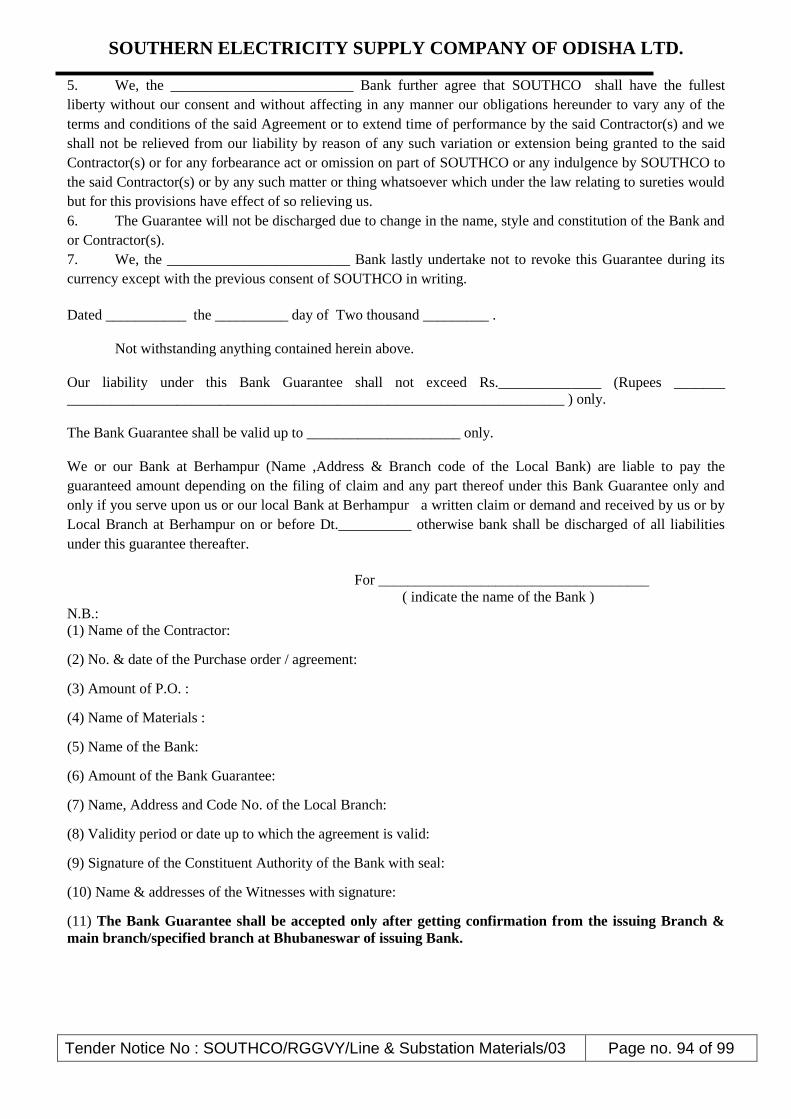
SOUTHERN ELECTRICITY SUPPLY COMPANY OF ODISHA LTD.
Tender Notice No : SOUTHCO/RGGVY/Line & Substation Materials/03 Page no. 94 of 99
5. We, the _________________________ Bank further agree that SOUTHCO shall have the fullest
liberty without our consent and without affecting in any manner our obligations hereunder to vary any of the
terms and conditions of the said Agreement or to extend time of performance by the said Contractor(s) and we
shall not be relieved from our liability by reason of any such variation or extension being granted to the said
Contractor(s) or for any forbearance act or omission on part of SOUTHCO or any indulgence by SOUTHCO to
the said Contractor(s) or by any such matter or thing whatsoever which under the law relating to sureties would
but for this provisions have effect of so relieving us.
6. The Guarantee will not be discharged due to change in the name, style and constitution of the Bank and
or Contractor(s).
7. We, the _________________________ Bank lastly undertake not to revoke this Guarantee during its
currency except with the previous consent of SOUTHCO in writing.
Dated ___________ the __________ day of Two thousand _________ .
Not withstanding anything contained herein above.
Our liability under this Bank Guarantee shall not exceed Rs.______________ (Rupees _______
____________________________________________________________________ ) only.
The Bank Guarantee shall be valid up to _____________________ only.
We or our Bank at Berhampur (Name ,Address & Branch code of the Local Bank) are liable to pay the
guaranteed amount depending on the filing of claim and any part thereof under this Bank Guarantee only and
only if you serve upon us or our local Bank at Berhampur a written claim or demand and received by us or by
Local Branch at Berhampur on or before Dt.__________ otherwise bank shall be discharged of all liabilities
under this guarantee thereafter.
For _____________________________________
( indicate the name of the Bank )
N.B.:
(1) Name of the Contractor:
(2) No. & date of the Purchase order / agreement:
(3) Amount of P.O. :
(4) Name of Materials :
(5) Name of the Bank:
(6) Amount of the Bank Guarantee:
(7) Name, Address and Code No. of the Local Branch:
(8) Validity period or date up to which the agreement is valid:
(9) Signature of the Constituent Authority of the Bank with seal:
(10) Name & addresses of the Witnesses with signature:
(11) The Bank Guarantee shall be accepted only after getting confirmation from the issuing Branch &
main branch/specified branch at Bhubaneswar of issuing Bank.

SOUTHERN ELECTRICITY SUPPLY COMPANY OF ODISHA LTD.
Tender Notice No : SOUTHCO/RGGVY/Line & Substation Materials/03 Page no. 95 of 99
ANNEXURE - IV (TECHNICAL DEVIATION FORMAT)
Clause No
Prescribed as per Tender Specification
Deviation in the bidder's Offer
Bidder’s Signature with Seal.
N.B:
The bidder has to mention all technical deviations in his offer which differs from the Technical Requirement of
this Tender in above format. Deviations not mentioned in above format but mentioned in any other format or in
any other part of the offer document shall not be considered as deviation and the bidder shall be deemed to have
accepted our technical requirement without deviation.

SOUTHERN ELECTRICITY SUPPLY COMPANY OF ODISHA LTD.
Tender Notice No : SOUTHCO/RGGVY/Line & Substation Materials/03 Page no. 96 of 99
ANNEXURE V (COMMERCIAL DEVIATION FORMAT)
Clause No
Prescribed as per Tender Specification
Provided in the bidder's Offer
Bidder’s Signature with Seal.
N.B:
The bidder has to mention all commercial deviations in his offer which differs from the Commercial
Requirement of this Tender in above format. Deviations not mentioned in this format but mentioned
in any other format or in any other part of the offer document shall not be considered as deviation and
the bidder shall be deemed to have accepted our commercial requirement without deviation.

SOUTHERN ELECTRICITY SUPPLY COMPANY OF ODISHA LTD.
Tender Notice No : SOUTHCO/RGGVY/Line & Substation Materials/03 Page no. 97 of 99
ANNEXURE-VI
SELF DECLARATION FORM
Name of the Purchaser: -------------------------
Tender Notice No: -----------------------------
Sir,
1. I / we, the undersigned do hereby declare that, I / we have never ever been blacklisted and /
or there were no debarring actions against us for any default in supply of material /
equipments or in the performance of the contract entrusted to us in any of the Electricity
Utilities of India.
2. In the event of any such information pertaining to the aforesaid matter found at any
given point of time either during the course of the contract or at the bidding stage, my
bid/contract shall be liable for truncation / cancellation / termination without any notice at
the sole discretion of the purchaser.
Yours faithfully,
Place-
Date-
Signature of the bidder with seal
(This form shall be duly filled-up and signed by the bidder & submitted along with the
original copy of the Bid.)

SOUTHERN ELECTRICITY SUPPLY COMPANY OF ODISHA LTD.
Tender Notice No : SOUTHCO/RGGVY/Line & Substation Materials/03 Page no. 98 of 99
ANNEXURE- VII
FORMAT FOR PAST SUPPLY EXPERIENCE
NAME OF THE BIDDER: -
DETAILS OF PURCHASE ORDER(S) EXECUTED DURING FY 2010-11 to 2011-12
Sl. No. P.O. No. Date
Order
Quanti
ty
Name
of the
Client
Quantity Supplied during
FY 11-12 FY 12-13 FY 13-14
TOTAL
I/We certify as under:
(i) The above information is true to the best of my / our knowledge and I / we undertake to produce
the invoice details on demand.
(ii) In the event of any deviation found later on pertaining to any of the above information either
during the course of contract or bidding stage, the bid/contract shall be liable for
truncation/cancellation/termination without any notice at the sole discretion of the purchaser.
Signature of the bidder with seal
NOTE: - Self attested photo copies of all Purchase Orders (all pages) need to be enclosed along
with the above format.
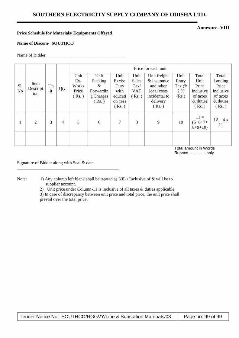
SOUTHERN ELECTRICITY SUPPLY COMPANY OF ODISHA LTD.
Tender Notice No : SOUTHCO/RGGVY/Line & Substation Materials/03 Page no. 99 of 99
Annexure- VIII
Price Schedule for Materials/ Equipments Offered
Name of Discom- SOUTHCO
Name of Bidder ___________________________________
Sl.
No
Item
Descript
ion
Un
it Qty.
Price for each unit
Unit
Ex-
Works
Price
( Rs. )
Unit
Packing
&
Forwardin
g Charges
( Rs. )
Unit
Excise
Duty
with
educati
on cess
( Rs. )
Unit
Sales
Tax/
VAT
( Rs. )
Unit freight
& insurance
and other
local costs
incidental to
delivery
( Rs. )
Unit
Entry
Tax @
2 %
(Rs.)
Total
Unit
Price
inclusive
of taxes
& duties
( Rs. )
Total
Landing
Price
inclusive
of taxes
& duties
( Rs. )
1 2 3 4 5 6 7 8 9 10
11 =
(5+6+7+
8+9+10)
12 = 4 x
11
Total amount in Words Rupees.………….only
Signature of Bidder along with Seal & date
______________________________________________
Note: 1) Any column left blank shall be treated as NIL / Inclusive of & will be to
supplier account.
2) Unit price under Column-11 is inclusive of all taxes & duties applicable.
3) In case of discrepancy between unit price and total price, the unit price shall
prevail over the total price.