Embed Size (px)
Citation preview

SOUTH AUSTRALIAN WATER CORPORATION
TECHNICAL STANDARD Issued by: Manager Engineering Issue Date: 01 May 1983
TS 59
SPECIFICATION FOR EWS DEPARTMENTAL FLANGES - 1983
Reference Specification Only

PLANNING & INFRASTRUCTURE
TS59 - EWS Flanges (1983)_2.docx Issued by: Manager Engineering Services
13 September 2004 Uncontrolled on printing
Page 2 of 25
© SA WATER 2007 This is an intellectual property of the South Australian Water Corporation. This document is copyright and all rights are reserved by SA Water. No part may be reproduced, copied or transmitted in any form or by any means without the express written permission of SA Water. The information contained in these Standards is strictly for the private use of the intended recipient in relation to works or projects of SA Water. These Standards have been prepared for SA Water’s own internal use and SA Water makes no representation as to the quality, accuracy or suitability of the information for any other purpose. It is the responsibility of the users of these Standards to ensure that the application of information is appropriate and that any designs based on these Standards are fit for SA Water’s purposes and comply with all relevant Australian Standards, Acts and regulations. Users of these Standards accept sole responsibility for interpretation and use of the information contained in these Standards. SA Water and its officers accept no liability for any loss or damage caused by reliance on these Standards whether caused by error, omission, misdirection, misstatement, misinterpretation or negligence of SA Water. Users should independently verify the accuracy, fitness for purpose and application of information contained in these Standards. The currency of these Standards should be checked prior to use.
APPROVAL TO DEVIATE FROM THIS STANDARD Approval may be granted by the Asset Owner to deviate from the requirements as stipulated in this Standard if the functional requirements (e.g. Asset Life) for the asset differs from those stated in the Standard, but is assessed as still being acceptable by the Asset Owner’s nominated representative. Any approval to deviate from the stated requirements of this Standard will not be seen as creating a precedent for future like project. Any request to deviate from this Standard must be carried out on a project by project basis where each alternate proposal will be individually assessed on its own merit.
MAJOR CHANGES INCORPORATED IN THE SEPTEMBER 2004 EDITION
The following lists the major changes to the May 1983 edition of TS 59, which have been incorporated in this edition:
1. Reformatted from DS to TS (Departmental Standard to Technical Standard), and updated referenced Australian Standards.
2. Conversion to a technical standard by removal of contractual conditions (to be included in the contract that references this standard).

PLANNING & INFRASTRUCTURE
TS59 - EWS Flanges (1983)_2.docx Issued by: Manager Engineering Services
13 September 2004 Uncontrolled on printing
Page 3 of 25
CONTENTS
© SA WATER 2007 ............................................................................................................... 2
APPROVAL TO DEVIATE FROM THIS STANDARD ........................................................... 2
MAJOR CHANGES INCORPORATED IN THE SEPTEMBER 2004 EDITION ..................... 2
CONTENTS .......................................................................................................................... 3
TABLES & FIGURES............................................................................................................ 4
REFERENCED DOCUMENTS .............................................................................................. 4
SECTION 1: SCOPE ............................................................................................................ 6
1.1 Scope ......................................................................................................................... 6
1.2 Extent ........................................................................................................................ 6
1.3 Designation ............................................................................................................... 6
1.4 Sa Water’s Representative ....................................................................................... 6
1.5 Further Information................................................................................................... 6
SECTION 2: BASIS OF DESIGN ......................................................................................... 7
2.1 Flange Dimensions ................................................................................................... 7
2.2 Flange and Pipe Thicknesses .................................................................................. 9
2.2.1 Mild Steel Flange and Pipe Thicknesses .......................................................... 9
2.2.2 Cast Iron Flange and Pipe Thicknesses ........................................................... 9
2.2.3 Cast Steel Flange and Pipe Thicknesses ......................................................... 9
2.3 Pressure Ratings ...................................................................................................... 9
SECTION 3: BOLTING .......................................................................................................10
3.1 General .....................................................................................................................10
3.2 Equivalent Sizes and Grades for Bolting ...............................................................10
3.2.1 Equivalent Sizes ..............................................................................................10
3.2.2 Material Grades for Bolts and Stud Bolts .........................................................10
3.3 Bolt Holes .................................................................................................................11
3.4 Bolt Fouling ..............................................................................................................11
SECTION 4: GASKETS ......................................................................................................11
4.1 General .....................................................................................................................11
4.2 Full Face Gaskets ....................................................................................................12
4.3 O Ring Gaskets ........................................................................................................12
4.4 Narrow Ring Gaskets ...............................................................................................12
SECTION 5: FLANGE FACING ..........................................................................................12
5.1 Flanges with Full Face Gaskets ..............................................................................12
5.2 Flanges with O Ring Gaskets ..................................................................................13
SECTION 6: WELDING ......................................................................................................13
SECTION 7: MATERIALS ..................................................................................................14
7.1 Flange and Pipe Materials .......................................................................................14
7.1.1 Mild Steel ........................................................................................................14

PLANNING & INFRASTRUCTURE
TS59 - EWS Flanges (1983)_2.docx Issued by: Manager Engineering Services
13 September 2004 Uncontrolled on printing
Page 4 of 25
7.1.2 Cast Iron .........................................................................................................14
7.1.3 Cast Steel .......................................................................................................14
7.2 Gasket Materials ......................................................................................................14
7.2.1 Full Face Gaskets ...........................................................................................14
7.2.2 O Ring Gaskets ...............................................................................................14
7.2.3 Sealing Rings for Dismantling Joints ...............................................................14
SECTION 8: HYDROSTATIC TESTING .............................................................................14
SECTION 9: FLANGES FOR SPECIFICATION ...................................................................15
SECTION 10: ASSEMBLY OF FLANGED JOINTS ............................................................15
10.1 Bolt Tightening ........................................................................................................15
10.1.1 Method of Tightening the Joint ........................................................................15
10.1.2 Calibration of Torque Device ...........................................................................16
10.1.3 Tightening Torques .........................................................................................16
10.2 Inserting Gaskets .....................................................................................................19
10.3 Joint Sealing ............................................................................................................19
APPENDIX A: EWS TABLES .............................................................................................20
APPENDIX B: EWS TABLES ............................................................................................. 20
TABLES & FIGURES
Table 10.1 - Metric Bolts and Stud Bolts, AS 2528 Grade 4.6...............................................16
Table 10.2 - Metric Bolts and Stud Bolts, AS 2528 Grade 8.8...............................................17
Table 10.3 - Inch Series Bolts, AS 2451 0r AS 2465 Grade 2 ...............................................18
Table 10.4 - Inch Series Bolts, AS 2465 Grade 5 .................................................................18
Figure 2. 1 - Flange Dimension Details .................................................................................. 8
Figure 5.1 - O-Ring Groove Details ...................................................................................... 13
Figure 6.1 - Weld Details for Steel Flanges .......................................................................... 13
REFERENCED DOCUMENTS
AS 1252: High strength steel bolts with associated nuts and washers for structural engineering
AS/NZS 1554: Structural Steel Welding
AS 1646: Elastomeric seals for waterworks purposes
AS 1830: Grey cast iron
AS 2074: Cast steels
AS 2129: Flanges for pipes, valves and fittings
AS/NZS 2451: Bolts, screws and nuts with British Standard Whitworth threads (rationalized series)

PLANNING & INFRASTRUCTURE
TS59 - EWS Flanges (1983)_2.docx Issued by: Manager Engineering Services
13 September 2004 Uncontrolled on printing
Page 5 of 25
AS/NZS 2465: Unified hexagon bolts, screws and nuts (UNC and UNF threads)
AS 2528: Bolts, stud bolts and nuts for flanges and other high and low temperature applications
AS 2619: Information and documentation - Format for information exchange
AS 4413: Steel tubes - Pressure application - Flash butt welding
Design Services Branch Manual Monograph P1.2

PLANNING & INFRASTRUCTURE
TS59 - EWS Flanges (1983)_2.docx Issued by: Manager Engineering Services
13 September 2004 Uncontrolled on printing
Page 6 of 25
SECTION 1: SCOPE
1.1 Scope
This Technical Standard supersedes all other details issued on metric flanges, and shall be used in place of AS 2129 "Flanges for pipes, valves and fittings", and AS 2528 "Bolts, stud bolts and nuts for flanges and other high and low temperature applications".
NOTE: Any flange details not shown in this Technical Standard or different from the details in this Technical Standard shall be to the approval of SA Water’s Representative. (Note comments in Clause 2.2 on minimum dimensions)
1.2 Extent
This Technical Standard gives details of steel and cast iron flange sizes and types normally approved by the SA Water. Apart from the few exceptions (see Clause 2.1) the flange drillings in this Technical Standard are identical with those in AS 2129. The flange and pipe thicknesses, the bolt grades and the O Ring types are not identical; these changes were made to develop more economical flanges than those in AS 2129. Flanges made in accordance with this Technical Standard can be bolted to flanges of 200 psi, 300 psi and 500 psi, except for 750 and 900 EWS Table-F flanges (see Clause 3.2 & Appendix A). This Technical Standard also gives details of flange joint assemblies which are not in AS 2129. The flanges in this Technical Standard shall only be used for pipes and fittings containing water in the temperature range of 10oC to 100oC. All other flanges shall need to be approved by SA Water’s Representative.
1.3 Designation
Flanges in accordance with this Technical Standard shall be designated: A D C F H as appropriate on all Drawings and Schedules to avoid confusion with flanges manufactured to other standards.
1.4 SA Water’s Representative
SA Water’s Representative will be nominated to the Contractor.
1.5 Further Information
Unless specified otherwise, all enquiries regarding this Technical Standard and or any other flange for special purpose or condition shall need to be approved by SA Water’s Representative.

PLANNING & INFRASTRUCTURE
TS59 - EWS Flanges (1983)_2.docx Issued by: Manager Engineering Services
13 September 2004 Uncontrolled on printing
Page 7 of 25
SECTION 2: BASIS OF DESIGN
2.1 Flange Dimensions
The flange dimensions used in this Technical Standard are identical to those used in AS 2129 except that: (1) Wider O Ring grooves are used to accommodate the soft rubber O Rings. (2) Different flange and shell thicknesses are used to achieve more economical
designs. (3) EWS Table-H flanges have been developed for sizes up to 1200 mm (only
to 600 mm in AS 2129). (4) The 1050 mm EWS Table-F flange dimensions detailed in this Technical
Standard are metricated from the 42", 300 psi flange and will not match AS 2129 Table F flange dimensions.
Although the 42" (1050 mm) flanges are included in the tables, these flanges should not be used except to match existing 42" flanges. Details of the flange dimensions are given in the EWS Tables in Appendix A and in Figure 2.1.

PLANNING & INFRASTRUCTURE
TS59 - EWS Flanges (1983)_2.docx Issued by: Manager Engineering Services
13 September 2004 Uncontrolled on printing
Page 8 of 25
Figure 2. 1 - Flange Dimension Details
.

PLANNING & INFRASTRUCTURE
TS59 - EWS Flanges (1983)_2.docx Issued by: Manager Engineering Services
13 September 2004 Uncontrolled on printing
Page 9 of 25
2.2 Flange and Pipe Thicknesses
2.2.1 Mild Steel Flange and Pipe Thicknesses
The flange tables (Appendix A) show the minimum pipe thicknesses t min. These thicknesses were determined by the Design Services Branch as the minimum pipe thicknesses that can be used to withstand the maximum pressure rating of the appropriate EWS Table and also withstand vacuum conditions in the pipe (refer to Design Services Branch Manual Monograph P 1.2). The flange tables show the minimum flange thicknesses T min. These thicknesses are the minimum flange thicknesses that can be used with the minimum pipe thicknesses t min. Either or both of these thicknesses can be increased above the minimum values without the joint being checked by SA Water’s Representative.
2.2.2 Cast Iron Flange and Pipe Thicknesses
The minimum flange thicknesses T min shown in the tables are the flange thicknesses used in AS 2129. The minimum pipe thicknesses t min shown in the tables are the minimum thicknesses that can be used with the minimum flange thicknesses T min to withstand the maximum pressure rating of the appropriate Table. Either or both of these thicknesses can be increased above the minimum values without the joint being checked by Engineering Services Group. Thicknesses less than t min or T min shall not be used without the approval of SA Water’s Representative.
2.2.3 Cast Steel Flange and Pipe Thicknesses
Cast steel welding neck flanges with O Ring gasket grooves are detailed for sizes 300 mm and above for EWS Table-H and sizes 600 mm and above for EWS Table-C EWS and EWS Table-F. This type of flange can be economical if a large number of flanges of the same size are required. These welding neck flanges have been designed to give economical joints and no variation on the dimensions is permissible without the approval of SA Water’s Representative.
2.3 Pressure Ratings
The flanges listed in the EWS Tables (Appendix A) have been designed to withstand the maximum test pressures of the appropriate tables. The working pressures for the tables are:
EWS Table-A up to 0.35 MPa EWS Table-D up to 0.7 MPa EWS Table-C up to 1.4 MPa EWS Table-F up to 2.1 MPa EWS Table-H up to 3.5 MPa

PLANNING & INFRASTRUCTURE
TS59 - EWS Flanges (1983)_2.docx Issued by: Manager Engineering Services
13 September 2004 Uncontrolled on printing
Page 10 of 25
Note: In AS 2129 Table C flanges have a maximum pressure rating of 1.2 MPa (see Section 9).
SECTION 3: BOLTING
3.1 General
It is preferred that metric bolts or stud bolts shall be used in the assembly of these flanges, but in some cases these may be unavailable. In such instances it is permissible to use an equivalent inch series bolt as set out in Clause 3.2. Inch series stud bolts should not be used unless all of the above three forms of bolting are unavailable. The SA Water’s Representative shall be referred to for details of inch stud bolts if they need to be used. The Flange Tables and Clause 3.2 give the minimum bolt and stud bolt material grades that shall be used. Higher material grades may be used. The use of high strength structural bolts in accordance with AS 1252 is not preferred. These bolts have an oversize hexagon head which could result in fouling as described in Clause 3.5. It should be noted that Clause 3.5 is based on normal size bolt heads. Stainless steel bolts shall not be used without approval from SA Water’s Representative. Where bolts are required to be hot dip galvanized the bolts and nuts shall be ordered with extra clearance to allow for the coating thickness. Galvanized bolts shall not be used with stainless steel flanges. Bolt tightening shall be in accordance with Section 10.
3.2 Equivalent Sizes and Grades for Bolting
3.2.1 Equivalent Sizes
Where metric bolting is unavailable, the following equivalent inch series bolt shall be used: M12 M16 M20 M24 M27 M30 M33 M36 M39 M45 1/2" 5/8" 3/4" 7/8" 1" 1 1/8" 1 1/4" 1 3/8" 1 1/2" 1 3/4"
3.2.2 Material Grades for Bolts and Stud Bolts
Two grades of bolting are used in this Standard:
(i) Normal grade bolts or stud bolts as specified below shall be used for all flanges except EWS Table-H EWS flanges.
Metric series bolts and stud bolts shall be in accordance with AS 2528 Grade 4.6.
Inch series bolts shall be in accordance with AS 2451, 28 tsi tensile strength, or AS 2465 Grade 2.

PLANNING & INFRASTRUCTURE
TS59 - EWS Flanges (1983)_2.docx Issued by: Manager Engineering Services
13 September 2004 Uncontrolled on printing
Page 11 of 25
(ii) High tensile bolts or stud bolts as specified below shall be used for all EWS Table-H flanges.
Metric series bolts and stud bolts shall be in accordance with AS 2528 Grade 8.8.
Inch series bolts shall be in accordance with AS 2465 Grade 5. High tensile bolting is indicated in Flange EWS Table-H by bold lettering.
3.3 Bolt Holes
For each size of flange, the number of bolts, their size, bolt hole diameter and the bolt circle diameter are given in the tables. The bolt holes shall be evenly pitched around the bolt circle. The angular disposition of the bolt holes shall be expressed as the angle from the centre plane of the pipe, valve or fitting to the centre line between the holes (e.g. Oo = off centres). When looking at the face of the flange a positive angle indicates a clockwise rotation and a negative angle indicates an anti clockwise rotation. If no angle is given it is assumed that the flange is to be drilled off centres. Except for the 750 and 900 EWS Table-F flanges, the flanges made in accordance with this Technical Standard can be bolted to 200 psi, 300 psi and 500 psi flanges. Normally the bolt holes of the imperial flanges will need to be enlarged if metric bolts are to be used.
3.4 Bolt Fouling
Care must be taken to ensure that the flange bolts do not foul with the pipe weld or valve body. A column giving the maximum pipe O.D. to prevent bolt fouling has been included in the tables. The values were calculated from: O.D. max = Pitch circle – width across corners – 30 diameter of the bolts This allows for a weld thickness of 15 mm (see Figure 6.1(a)) or a maximum radius of 15 mm on valves or fittings. Steel welding neck details have been chosen so that bolt fouling does not occur provided the internal pipe diameters shown in Design Services Branch Manual Monograph P 1.2 are used. Where the pipe O.D. exceeds the maximum value of pipe O.D. shown in the tables, it may still be possible to use the flange. In this situation the flange should be drawn out and assessed for the particular application.
SECTION 4: GASKETS
4.1 General
The flanges in this Technical Standard do not use the same gaskets as those used in AS 2129. Only two types of gasket are applicable to the flanges within this Technical Standard. SA Water Representative will approve the gaskets to be used.

PLANNING & INFRASTRUCTURE
TS59 - EWS Flanges (1983)_2.docx Issued by: Manager Engineering Services
13 September 2004 Uncontrolled on printing
Page 12 of 25
4.2 Full Face Gaskets
This type of gasket shall only be used on flanges smaller than 300 mm for EWS Table-H and 600 mm for other tables. The sealing capability of this type of gasket is relatively poor and over tightening the bolts to obtain a seal will normally be unsuccessful (it will cause bolt yielding but would be unlikely to cause damage to the flange joint).
4.3 O Ring Gaskets
The standard O Ring gasket used in AS 2129 is of small diameter and made of relatively hard rubber; this type of gasket requires carefully machined joint surfaces but it can be used for very high pressures. SA Water practice is to use a large diameter but softer rubber O Ring; this type of gasket does not require such carefully machined joint surfaces but its maximum pressure rating is lower than the standard O Ring. This is of no consequence for the pressures normally involved in SA Water activities.
4.4 Narrow Ring Gaskets
The flanges in this Technical Standard are not designed for use with narrow ring gaskets (i.e. those gaskets that do not extend to the full flange diameter) because of the high stresses that can be induced during initial bolt tightening. These gaskets shall not be used without approval from SA Water’s Representative (see also Clause 10.3).
SECTION 5: FLANGE FACING
5.1 Flanges with Full Face Gaskets
All standard flanges in this Technical Standards used with full face gaskets shall be plain faced (i.e. raised faces shall not be used without approval from SA Water’s Representative). The contact surfaces shall be machined as follows: i) For nominal sizes 300 mm and smaller a continuous spiral groove
generated by a 1.5 mm radius round nosed tool at a feed of approximately 0.8 mm per revolution.
ii) For nominal sizes above 300 mm a continuous spiral groove generated by
a 3.0 mm radius round nosed tool at a feed of approximately 1.2 mm per revolution.
iii) Alternatively, cast iron flanges 150 mm and smaller may be faced on a
production milling machine using one pass of a large multi tooth cutter.

PLANNING & INFRASTRUCTURE
TS59 - EWS Flanges (1983)_2.docx Issued by: Manager Engineering Services
13 September 2004 Uncontrolled on printing
Page 13 of 25
5.2 Flanges with O Ring Gaskets
For joints containing an O Ring gasket, the faces of the two flanges and the sides and bottom of the O Ring groove shall be machined to a surface texture at least as smooth as N8 (3.2 um Ra). Details of the O Ring groove are shown in Figure 5.1.
Figure 5.1 - O-Ring Groove Details
SECTION 6: WELDING All welding of flanges shall be in accordance with AS 4413: “Steel tubes - Pressure application - Flash butt welding”. That standard shows various alternative arrangements for welding flanges to pipes. The arrangements used for the standard flanges with in this Technical Standard are shown in Figures 6.1(a) and 6.1(b) of this Standard (TS 59) Alternative weld details shall not be used without approval from SA Water’s Representative.
Figure 6.1 - Weld Details for Steel Flanges

PLANNING & INFRASTRUCTURE
TS59 - EWS Flanges (1983)_2.docx Issued by: Manager Engineering Services
13 September 2004 Uncontrolled on printing
Page 14 of 25
SECTION 7: MATERIALS
7.1 Flange and Pipe Materials
7.1.1 Mild Steel
All mild steel flanged joints shall be made from steel equal to or better than Grade 250 steel in accordance with AS/NZS 1554.
7.1.2 Cast Iron
All cast iron flanged joints shall be made from cast iron which is equal to or better than Grade T 200 cast iron in accordance with AS 1830.
7.1.3 Cast Steel
All cast steel flanged joints shall be made from cast steel which is equal to or better than Grade C3 cast steel in accordance with AS 2074.
7.2 Gasket Materials
7.2.1 Full Face Gaskets
Full face gaskets shall be made from 2 ply of canvas and 3 ply of rubber 55 65 Duro hardness, and shall have a total thickness of 3 mm (1/8").
7.2.2 O Ring Gaskets
O Ring gaskets shall be made from 10 mm nominal diameter rubber having a ring hardness of between 30 to 40 Duro in accordance with AS 1646, Appendix A.
7.2.3 Sealing Rings for Dismantling Joints
The Sealing Ring diameter is listed on the appropriate dismantling joint Drawing. The rubber shall have a ring hardness of between 30 to 40 Duro in accordance with AS 1646, Appendix A.
SECTION 8: HYDROSTATIC TESTING When hydrostatic testing of pipes or fittings is required, the maximum test pressure shall not exceed 1.5 times the rated pressure for mild steel or cast steel flanges or 2.0 times the rated pressure for cast iron flanges.
PLANNING & INFRASTRUCTURE
TS59 - EWS Flanges (1983)_2.docx Issued by: Manager Engineering Services
13 September 2004 Uncontrolled on printing
Page 15 of 25
SECTION 9: FLANGES FOR SPECIFICATION Where flanges are specified for valves, pumps and other fittings made outside of SA Water, these shall be specified to be in accordance with AS 2129. Refer to Clause 2.1 for further information regarding the use of AS 2129. Where flanges are required from outside organisations in the pressure range 1.2 - 1.4 MPa, these flanges shall be specified as Table E flanges to AS 2129, and the mating flanges shall also be EWS Table-E. This is a rare occurrence so to avoid confusion EWS Table-E flanges are not detailed in this Standard; the details of these flanges shall be given on Drawings when they are required.
SECTION 10: ASSEMBLY OF FLANGED JOINTS
10.1 Bolt Tightening
10.1.1 Method of Tightening the Joint
The specified method of bolt tightening is equally applicable to galvanized and ungalvanized bolts. The bolts shall be tightened by torque control, using the specified lubricant, in accordance with the following procedure: (i) Lubrication Before assembly, the nuts shall be checked to ensure that they are free
running on the bolts (especially where galvanized bolts and nuts are used), and then the bolt and nut threads shall be lubricated with Molycoat P74 molybdenum grease.
On assembly care shall be taken to ensure that the mating face of the nut is
also lubricated with Molycoat P74 molybdenum grease. (ii) Assembly After assembly, all bolts and nuts in the joint shall be tightened evenly to a
snug tight condition. (iii) Tightening Each nut shall be tightened with a continuous smooth action using a
calibrated torque device set to the appropriate assembly torque, for different types of bolt and bolt tension.
This assembly torque is designed to achieve a preloading in the bolt
expressed in percentage of the bolt yield stress.
PLANNING & INFRASTRUCTURE
TS59 - EWS Flanges (1983)_2.docx Issued by: Manager Engineering Services
13 September 2004 Uncontrolled on printing
Page 16 of 25
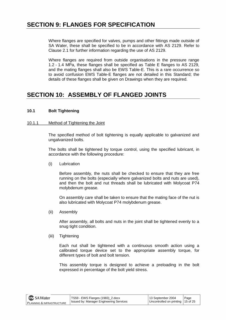
To achieve uniform clamping effect on flanges, the specified torque shall be reached in four stages, with each bolt in the flange tightened to one stage before proceeding to the next stage.
Stage 1 Approximately 50% of final torque Stage 2 Approximately 80% of final torque Stage 3 Final Torque Stage 4 Repeat Final Torque NOTE: With O Ring joints it is essential that there is metal to
metal contact at the outside diameter when the joint has been tightened. If this is not the case the joint should be dismantled and checked (see Clause 10.3).
10.1.2 Calibration of Torque Device
The torque device shall be calibrated regularly and for large projects where large numbers of bolts are to be tightened an approved load cell shall be used for calibration. A suitable load cell will be made available SA Water’s Representative. Calibration shall consist of tightening at least three sample bolts complete with nuts and washers, lubricated with Molycoat P74 molybdenum grease as specified in Clause 10.1.1(i).
10.1.3 Tightening Torques
The following tables show the tightening torques for normal grade and high tensile grade bolts for both metric and inch series. The torque is specified in Nm for the metric bolts and lb ft for the inch series bolts. The torque values listed have been determined on the basis that for O ring joints an initial bolt stress of 100 MPa (6.47 tsi) is required to seal the joint at low pressure and for full face gaskets the bolts must be tightened to 80% of yield stress to achieve a leak tight joint at full pressure.
Table 10.1 - Metric Bolts and Stud Bolts, AS 2528 Grade 4.6
. Metric Bolts and Stud Bolts Material: AS 2528 Grade 4.6 Tensile Strength 400 MPa Yield Stress 240 MPa Flanges from EWS Tables-A, D, C, F use:
Bolt Sizes Tightening Torque (Nm)
O-Ring Joint Gasket Joint
M12 13 25
M16 31 60
M20 62 120
M24 105 200

PLANNING & INFRASTRUCTURE
TS59 - EWS Flanges (1983)_2.docx Issued by: Manager Engineering Services
13 September 2004 Uncontrolled on printing
Page 17 of 25
M27 150 290
M30 205 390
M33 285 545
M36 370 -
M39 460 -
Table 10.2 - Metric Bolts and Stud Bolts, AS 2528 Grade 8.8
Metric Bolts and Stud Bolts
Material: AS 2528 Grade 8.8 Tensile Strength 800 MPa Yield Stress 640 MPa Flanges from EWS Table-H use:
Bolt Sizes Tightening Torque (Nm)
O-Ring Joint Gasket Joint
M12 13 65
M16 31 160
M20 62 320
M24 105 535
M27 150 -
M30 205 -
M33 285 -
M36 370 -
M39 460 -
M45 695 -

PLANNING & INFRASTRUCTURE
TS59 - EWS Flanges (1983)_2.docx Issued by: Manager Engineering Services
13 September 2004 Uncontrolled on printing
Page 18 of 25
Table 10.3 - Inch Series Bolts, AS 2451 0r AS 2465 Grade 2
Inch Series Bolts Material: B.S.W. Thread form AS 2451 Tensile Strength 28 tsi (432 MPa) Yield Stress 16 tsi (247 MPa) or U.N.C. Threadform AS 2465 Grade 2 Tensile Strength 60 000 psi Yield Stress 36 000 psi
Flanges from EWS Tables-A, D, C, F use:
Bolt Sizes Tightening Torque (lb-ft)
O-Ring Joint Gasket Joint
1/2” 11 22
5/8” 22 44
3/4” 40 80
7/8” 60 120
1” 95 185
1 1/8” 130 260
1 1/4” 185 370
1 3/8” 250 -
1 1/2” 315 -
Table 10.4 - Inch Series Bolts, AS 2465 Grade 5
Inch Series Bolts Material: U.N.C. Threadform AS 2465 Grade 5 Tensile Strength 105 000 psi Yield Stress 81 000 psi
Flanges from EWS Table-H use:
Bolt Sizes Tightening Torque (lb-ft)
O-Ring Joint Gasket Joint
1/2” 11 22
5/8” 22 44
3/4” 40 80
7/8” 60 120
1” 95 185
1 1/8” 130 260
1 1/4” 185 370
1 3/8” 250 -
1 1/2” 315 -

PLANNING & INFRASTRUCTURE
TS59 - EWS Flanges (1983)_2.docx Issued by: Manager Engineering Services
13 September 2004 Uncontrolled on printing
Page 19 of 25
10.2 Inserting Gaskets
It is permissible to use BETA 2619 adhesive to hold an O Ring Gasket in position while the joint is being assembled. The use of any hard setting glue should be avoided. No attempt shall be made to assemble an O Ring joint if the O Ring gasket does not fit exactly in its groove; a new gasket shall be obtained. Hard setting glue may be used to hold full face gaskets in position to simplify joint assembly.
10.3 Joint Sealing
Where effective sealing of joints cannot be achieved, a check shall be made that misalignment of the flanges is not causing excessive forces and distortion of the joint. The presence of misalignment can be detected by observing whether there is any relative movement (in any direction) of the mating flanges as the flange bolts are untightened. If large misalignment forces are present, the misalignment shall be corrected before attempting to make the joint. All flanges shall be checked before assembly to ensure that there is no protruding lining or foreign material on the flange faces or in O Ring grooves which could prevent a seal. If full face gasket joints cannot be sealed at the specified bolt yield, it is permissible to progressively increase the bolt tension until yield of the bolts is reached, although in larger flange sizes this is unlikely to be successful. Where effective sealing cannot be achieved with a full face gasket, an O Ring shall be used. SA Water’s Representative is to be consulted on the methods available for converting a full face flange joint to an O ring joint.

PLANNING & INFRASTRUCTURE
TS59 - EWS Flanges (1983)_2.docx Issued by: Manager Engineering Services
13 September 2004 Uncontrolled on printing
Page 20 of 25
APPENDIX A: EWS TABLES Contains: EWS Table-A EWS Table-C EWS Table-D EWS Table-F EWS Table-H

PLANNING & INFRASTRUCTURE
TS59 - EWS Flanges (1983)_2.docx Issued by: Manager Engineering Services
13 September 2004 Uncontrolled on printing
Page 21 of 25

PLANNING & INFRASTRUCTURE
TS59 - EWS Flanges (1983)_2.docx Issued by: Manager Engineering Services
13 September 2004 Uncontrolled on printing
Page 22 of 25

PLANNING & INFRASTRUCTURE
TS59 - EWS Flanges (1983)_2.docx Issued by: Manager Engineering Services
13 September 2004 Uncontrolled on printing
Page 23 of 25

PLANNING & INFRASTRUCTURE
TS59 - EWS Flanges (1983)_2.docx Issued by: Manager Engineering Services
13 September 2004 Uncontrolled on printing
Page 24 of 25

PLANNING & INFRASTRUCTURE
TS59 - EWS Flanges (1983)_2.docx Issued by: Manager Engineering Services
13 September 2004 Uncontrolled on printing
Page 25 of 25


![THE SOUTH AUSTRALIAN GOVERNMENT GAZETTE · 712 the south australian government gazette [28 february 2008. 28 february 2008] the south australian government gazette 713. 714 the south](https://img.dokumen.tips/doc/110x75/60a2527d46c825459e780070/the-south-australian-government-gazette-712-the-south-australian-government-gazette.jpg)