Embed Size (px)
Citation preview

Sounding Better!
Updates for Dual Head Multibeam Systems
By Mike Kalmbach
INTRODUCTIONThe dual head multibeam allows you to extend coverage. Instead of a single head pointing straight down, two heads point off at angles port and starboard—typically around 30 degrees. Multibeam manufacturers offer dual head devices as an alternative to interferometry systems.I think we at HYPACK do a good job supporting dual head systems. Although the heads are merged for proper display, coverage and editing, the offsets are kept separate. Separate offsets matter as the heads are independent of one another and may be pointed pretty much anywhere.Given the time and hard work getting this right, I’ve been frustrated lately. There’s some confusion in the industry as to whether we do have it (specifically, the patch testing) right. Perhaps the confusion originates from people who haven’t taken the time to understand what we do, and perhaps from devious software marketers. Maybe the updated coverage mapping will help people understand. In truth our dual head software works very well and our patch test has always been ahead of the curve.Here are the recent updates, available now through HYPACK tech support and in HYPACK® 2018 (HYSWEEP 17.2.12 program versions). After the updates, read on for a detailed review of dual head patch testing in HYPACK® / HYSWEEP®.
UPDATE 1: RESON IDH SYSTEMHYSWEEP® SURVEY now supports the Integrated Dual Head (IDH) hardware. Just check the box in dual T20P or T50P driver setup (Figure 1).
FIGURE 1. Selection for IDH Hardware.
September / 2017 1

UPDATE 2: COVERAGE MAPPINGYou can now show head 1 only, or head 2 only, which is very useful for patch testing. The previous versions always showed combined coverage. Use HYSWEEP® View Options, Multibeam Display tab (Figure 2).
FIGURE 2. New Coverage Option in HYSWEEP® View Options. Useful for dual head patch tests.
DUAL HEAD PATCH TESTINGNow the review. The data is from an Odom MB1 system, but the process applies to any dual head multibeam.
LATENCY TESTThe latency test is straightforward in that there is no need to distinguish between heads one and two. That is, the rules for single head latency testing (two survey lines run over varying depth in the same direction at different speeds) apply.Figure 3 shows the survey lines run over a channel side slope. The speed differential is 3.5 knots.
2

FIGURE 3. Latency Test Map View—Track lines in red and green. A-B connects the patch test cross section.
Figure 4 shows the patch test results from HYSWEEP® MBMAX64 (64-bit HYSWEEP® EDITOR). Perfectly acceptable. The latency test confirms there is no GPS latency. Something to watch out for in latency testing is the settlement difference between fast and slow lines. A 50 cm vertical adjustment is required in this example. Test results are biased without the adjustment. That is, depth difference is compensated with latency, which is clearly not good.
September / 2017 3

FIGURE 4. Latency Test Results!
ROLL TESTThe latency test was easy, the roll test requires some thinking and planning. We want to use trusted beams, so trimming is done at +/- 65 degrees giving coverage of 2.14 times water depth [tan(65)]. In 16 meters of water, optimal line spacing is 35 meters. Lines are run over a flat bottom in a serpentine pattern.Simply put, we want to overlap head one beams for head one roll bias, and the same for head two.Figure 5 shows the survey lines and location of A-B cross section.
NOTE: While the lines are run over a bank, the patch test cross section is cut in the channel flat area.
4
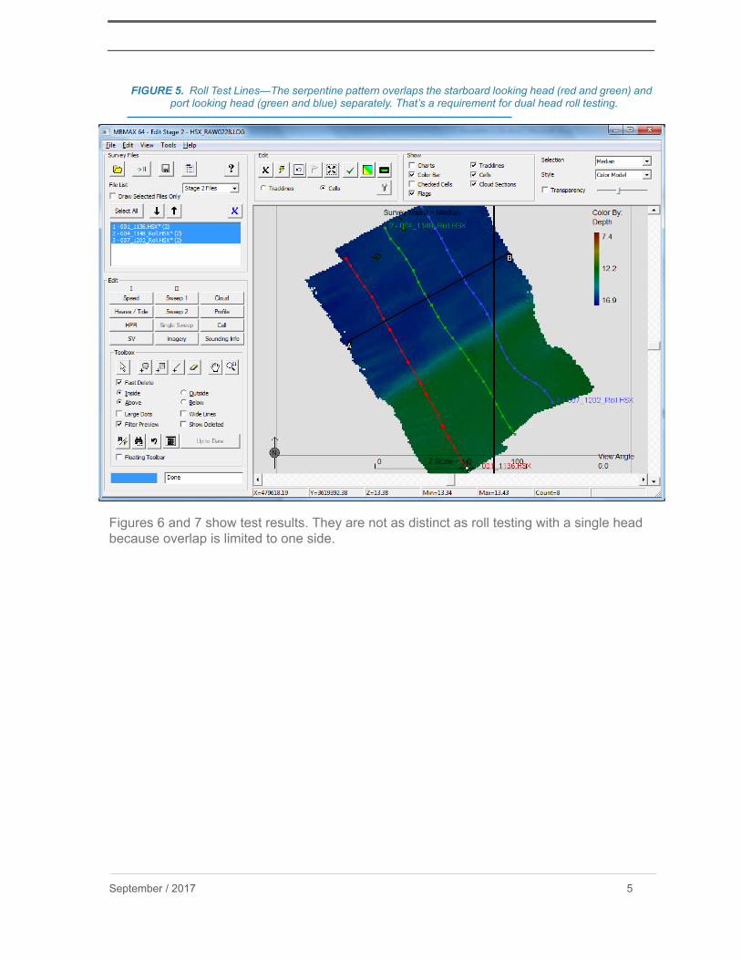
FIGURE 5. Roll Test Lines—The serpentine pattern overlaps the starboard looking head (red and green) and port looking head (green and blue) separately. That’s a requirement for dual head roll testing.
Figures 6 and 7 show test results. They are not as distinct as roll testing with a single head because overlap is limited to one side.
September / 2017 5

FIGURE 6. Roll Test Result; Head One.
FIGURE 7. Roll Test Result; Head Two.
6

PITCH TESTThe pitch test can be run testing heads separately or together. Either way, the rules are the same as with a single head system – reciprocal lines at survey speed over variable depth.With the dual MB1 the result is the same whether heads are tested together or separately -1.5 degrees (Figures 8 and 9).
FIGURE 8. Pitch Test Lines and Location of A-B Cross Section.
September / 2017 7

FIGURE 9. Pitch Test Result Testing Both Heads Together.
YAW TESTSingle or dual head, it’s hard to get yaw alignment pinned down. Perhaps that’s because misalignment doesn’t affect depth, only depth position. Depth position is important though, so we push forward and do the best we can. As with the other tests, the right answer comes from averaging multiple patch test surveys!As with single head, the dual head yaw test uses parallel lines run in the same direction over depth changes at survey speed. The question is “What is the correct line spacing?”.In this instance, depth varies from 16 to 12 meters (average 14 meters). We want beams near nadir from the first line to overlap beams at 45 degrees from the second at average depth. That’s simple then; line spacing = average water depth.Figures 10 and 11 show survey lines run over the channel side slope and the patch test cross sections (A-B) cut for testing heads one and two respectively. Figures 12 and 13 are the results.
8

FIGURE 10. A-B Cross Section for Head 1 Yaw Test—Overlays head 1 beams near nadir (red) with outer beams from the second line (green).
FIGURE 11. A-B Cross Section for Head 2 Yaw Test.
September / 2017 9

FIGURE 12. Head One Results from a Single Test.
FIGURE 13. Head Two Results from a Single Test.
10

As mentioned, the only way to find true patch alignment is to average multiple tests. Figure 14 shows the average from four tests done with different line pairings.
FIGURE 14. Average Result from Four Tests—Head 1 (left) and Head 2 (right).
September / 2017 11