Embed Size (px)
Citation preview
SOPRA

SOPRA
OUR CRUSADE ...
Since his founding of Focal, Jacques Mahul has launched ambitious projects just to push the limits of the loudspeaker: the Audiom 15A in 1981 ; the TC120 FC for magnetic power; the first K2 sandwich cones in 1986 creating a low-mass, high-stiffness diaphragm. Conceived originally as prototypes these projects can sometimes seem approximate but have given birth to numerous products that have made Focal a leader, envied in the field of loudspeaker science. The basic aim is very simple: creating the maximum magnetic force driving minimum moving mass for an expressive sound. This has also not changed in 35 years and this consistency of purpose has allowed us to make very significant progress:
multi-ferrites/Power Flower, EM and IAL in the first respect, and W, Flax and Beryllium diaphragms in the second. So many milestones that have built the reputation of the Brand.
But this quest for the Holy Grail in the field of the sound transducer is not always kept pace with the expectations of markets always wanting more convenience and miniaturisation.
Also, in parallel, to provide the means to continue ‘crusade’ we had to be pragmatic by:
• Passing our technology down to more affordable products (the JMlab series in the 80’ is a good example);
• Applying our expertise to other areas such as car audio and pro audio, where we have been active for 25 and 10 years respectively;
• More recently, expanding our expertise by exploring new promising fields such as headphones and sound bar.
This has been in order to maintain a company of critical mass, able still to explore the limits, and so continue to exist and grow in an industry that has seen many changes over the last 30 years. So has Focal built and consolidated.
The work of recent years that led to the development of our Flax sandwich clearly demonstrated that our W sandwich W (with the mastery that we have for almost 20 years as well as its many improvements) remains unsurpassed for making cone woofers or midrange drivers. For tweeters, beryllium likewise remains the ultimate material, combining all the best qualities (lightness, stiffness, damping). The only way forward was to work more closely on the driver suspension. We had already begun this work on the woofer-midrange of the Diablo Utopia by developing a new spider to "soft clip" mechanically, and by improving the join to the cone surround when developing Utopia III in 2008. Since then, the simulation tools at our disposal have
improved, allowing us to analyze the nonlinearities that cause distortion, mainly in the midrange, where the 1-1.5kHz area remains very critical. Whereas in Utopia III, with improvements wrought by the third-generation W sandwich and laser cutting, we could hand-build the drive unit to limit these distortions, this is not possible in our premium ranges for obvious cost reasons.
The problem is well known: there is a sudden change in mechanical impedance where the wave passes from the cone to the surround, which itself radiates sound and has a "boomerang" effect, causing deformation of the cone. Many attempts to resolve this have been considered by our competitors but none
is satisfactory, since all are detrimental to cone travel and cause dynamic compression. A committed research project of more than two years duration has allowed us to develop a remarkable solution by addressing the problem at source, without limitation of cone movement, using a "TMD" suspension for which a patent was filed in the third quarter of 2014.
OUR tEChnOlOgiCAl ADvAnCES in 2014
MAtERiAlS AnD DiAPhRAgMS
In continuation of the work done for the woofer-midrange driver of the Diablo Utopia, and with hindsight and experience gained through the manufacture of thousands of drive units revealing the high criticality of the cone-suspension assembly, we realized that the multitude of parameters involved made it illusory to suppose we could develop a solution empirically. We had instead to develop a computer simulation model that represents this complex mechanical connection well enough, first to correlate the results observed from many prototypes, and second to develop a non-empirical, reliable solution. Today, computing power is enabling
the finite element method to calculate the dynamic response of complex objects and thus to predict the behaviour of virtual prototypes. And consequently to devise accurate and relevant solutions.
Standard measures such as frequency response, distortion, even laser interferometry, highlight the problem but as a snapshot, a still photograph. What we need is a ‘movie’ to reveal the motion, understand the phenomenon as a whole and thus devise effective solutions. ‘Patch’ correction of static defects linearizing the response curve can be devastating to dynamic behaviour. The midrange is
undoubtedly the most complex area and the most demanding musically; it is a key element of the sound signature of Focal, and spoiling its resolution is simply not an option!
With a numerical model that correlated closely with classical acoustic measurements on numerous prototypes (over a hundred have been tested!), we could at last consider a remedy.The computer model is used to accurately assess the addition of mass or stiffness to the suspension, the added masses acting as a dynamic vibration absorber. The technique, which is well known, is termed a "tuned mass" or "harmonic" damper.
tMD SUSPEnSiOn OR OUR MiDRAngE OBSESSiOn...
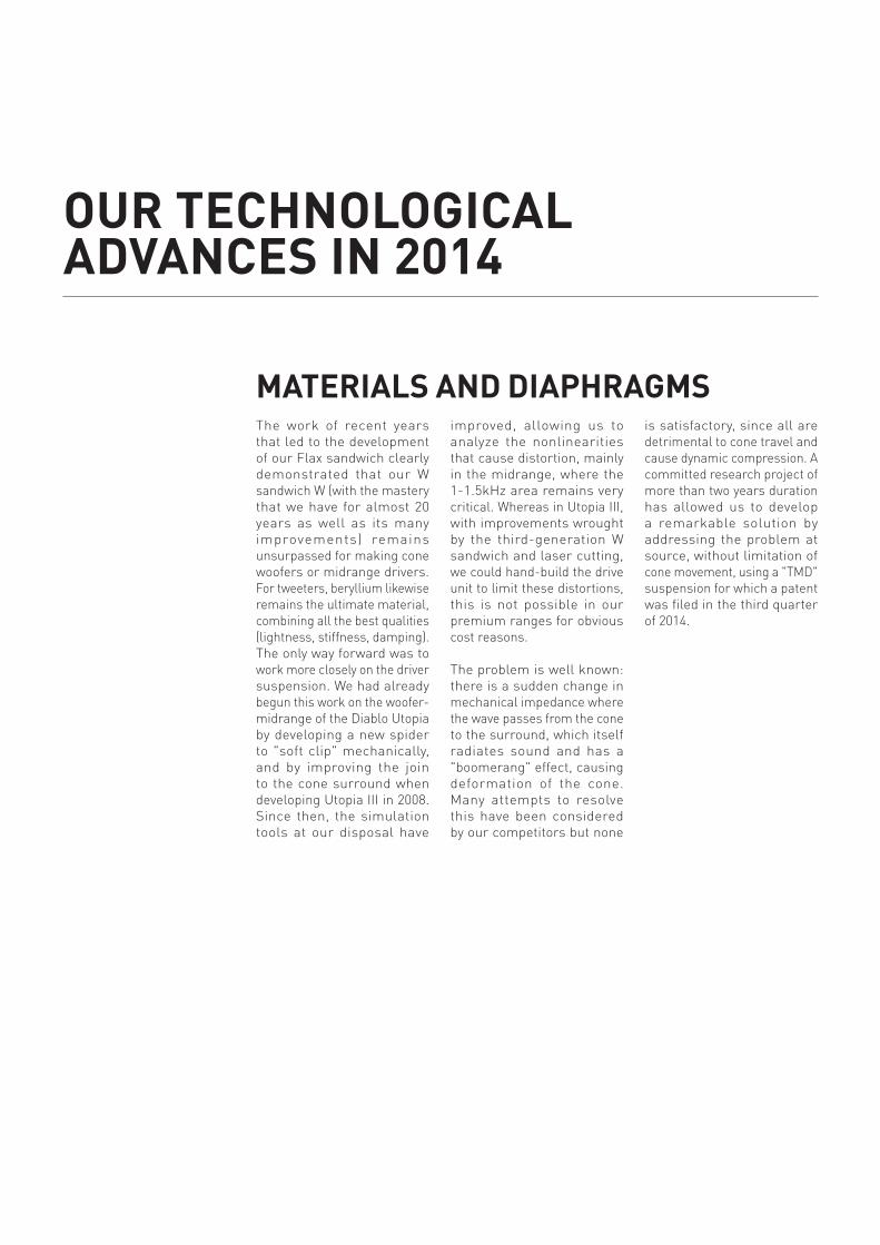
It was used with great success in the suspension of the Renault R25 F1 car in 2005 – and was quickly banned because it was considered anti-competitive by the FIA! It is also the basic principle of anti-seismic systems for modern skyscrapers. (fig A)
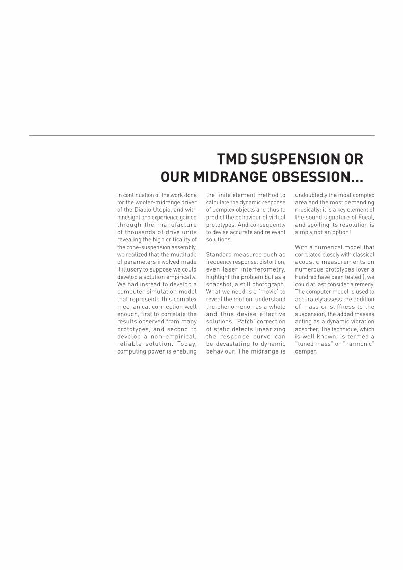
This principle applied to a drive unit surround consists of two small circular rings, acting as additional masses, which oscillate in opposition to the resonance frequency of the surround. (fig B)
This device offers major advantages. We are able to:
• Use an exponential cone profile that extends the bandwidth to more than 5kHz and thus achieve better transient response;
• Choose a very light surround, eliminating the resonance that is even stronger when the mass is low;
• Damp resonance in the direction of the sound radiation (the radial plane) whereas competitors’ devices damp circumferential resonances of the suspension. (fig C et D)
Thus we can combine benefits which were prev iously irreconcilable: low mass, opt imum damping and extension of the frequency response. (fig E)
This leads to several benefits at the listening level: improved transient response coupled with a flat frequency response and reduced distortion, of the order of more than 50 per cent in an area where the ear is highly sensitive around 2kHz. This results in more accurate timbre, improved definition and better stereo imaging. To clarify the last point, the resonance of a conventional surround blurs the soundstage, especially when the resonance is marked. TMD suspension eliminates the problem at source. (fig F)
Fig A: The principle of the tuned harmonic damper (TMD) is shown in the graph, above. A system comprising a single mass m1 and spring k1 has a marked resonance (red trace). Addition of a second mass-spring system, m2/k2 as shown in the diagram, results in two resonance peaks (pink trace in the graph). If the anti-resonance dip is aligned with the resonance of m1/k1 we obtain the green curve and finally, with careful application of damping, the black curve – the resonance has virtually disappeared! Photo down shows the TMD (m2 = 660 tonnes) used in the skyscraper Taipei 101.
Frequency Hz
120100806040200
-10
0
10
20
30
40
50
60
Tran
smis
sibi
lity
T (d
B)
with absorber, optimized damping
with absorber, small damping
with absorber, no damping
without absorber
m2
m1
c2
c1
k2
k1
Frequency Hz
120100806040200
-10
0
10
20
30
40
50
60
Tran
smis
sibi
lity
T (d
B)
with absorber, optimized damping
with absorber, small damping
with absorber, no damping
without absorber
m2
m1
c2
c1
k2
k1
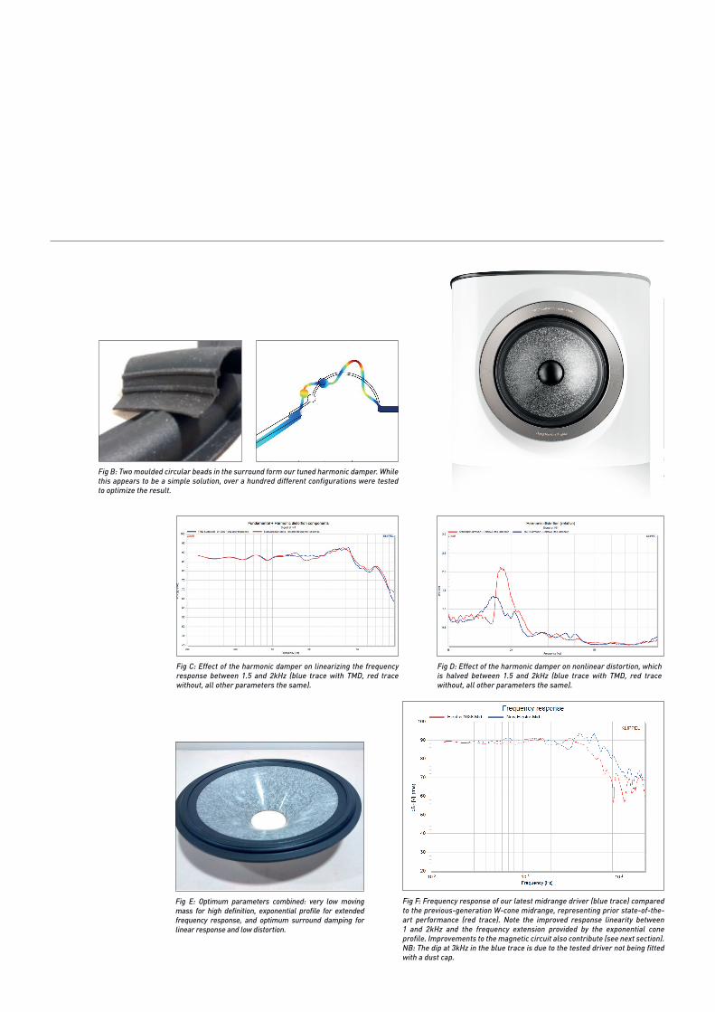
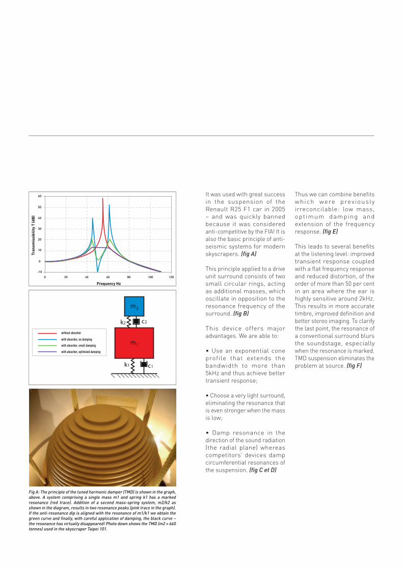
Fig C: Effect of the harmonic damper on linearizing the frequency response between 1.5 and 2kHz (blue trace with TMD, red trace without, all other parameters the same).
Fig D: Effect of the harmonic damper on nonlinear distortion, which is halved between 1.5 and 2kHz (blue trace with TMD, red trace without, all other parameters the same).
Fig B: Two moulded circular beads in the surround form our tuned harmonic damper. While this appears to be a simple solution, over a hundred different configurations were tested to optimize the result.
Fig E : Les meilleurs paramètres enfin conciliables : très faible masse de l’équipage mobile pour haute définition, profil exponentiel à réponse en fréquence et amortissement optimal pour grande linéarité et faible distorsion.
Fig F: Frequency response of our latest midrange driver (blue trace) compared to the previous-generation W-cone midrange, representing prior state-of-the-art performance (red trace). Note the improved response linearity between 1 and 2kHz and the frequency extension provided by the exponential cone profile. Improvements to the magnetic circuit also contribute (see next section). NB: The dip at 3kHz in the blue trace is due to the tested driver not being fitted with a dust cap.
Fig E: Optimum parameters combined: very low moving mass for high definition, exponential profile for extended frequency response, and optimum surround damping for linear response and low distortion.
In recent decades our work on the magnetic circuit primarily comprised optimizing the magnetic field strength and therefore the force factor, a key criterion in terms of acceleration and thus expressive musical rendering.
Also we have:
• Developed motors equipped with advanced magnetic materials for the Utopia III and the Be tweeter, and field coil woofers w i th our EM technology;
• Reduced magnetic losses by optimizing the geometry of the pole piece, sizing of the plate-core (T-Yoke) and flatness of field plates, as in the multi-ferrite Power Flower midrange
unit. Further research work on a concept speaker with its voice-coil around the circumference of a flat diaphragm (US Patent 2013/0064413) was very informative.
To improve performance further is an extremely complex problem because this is a dynamic electromagnetic sys te m w i t h m u l t i p le interrelated factors. As the coil moves in the gap it modulates the magnetic field (Lenz’s law), in different ways depending on its position. And as the voice coil current varies depending on the music signal, it induces Eddy currents in the magnetic circuit which have the effect of slowing the movement of the coil.
Both these phenomena vary according to a third factor, which is the frequency. Ideally we would like to eliminate these effects but they are very complex and only sophisticated numerical modelling could help us progress. This work, undertaken over three years of research, has delivered important improvements, similar in significance to that achieved mechanically with the "Gamma structure" used in our cabinets to provide an inert, neutral foundation for the drive units.
REFining thE MAgnEtiC CiRCUitS
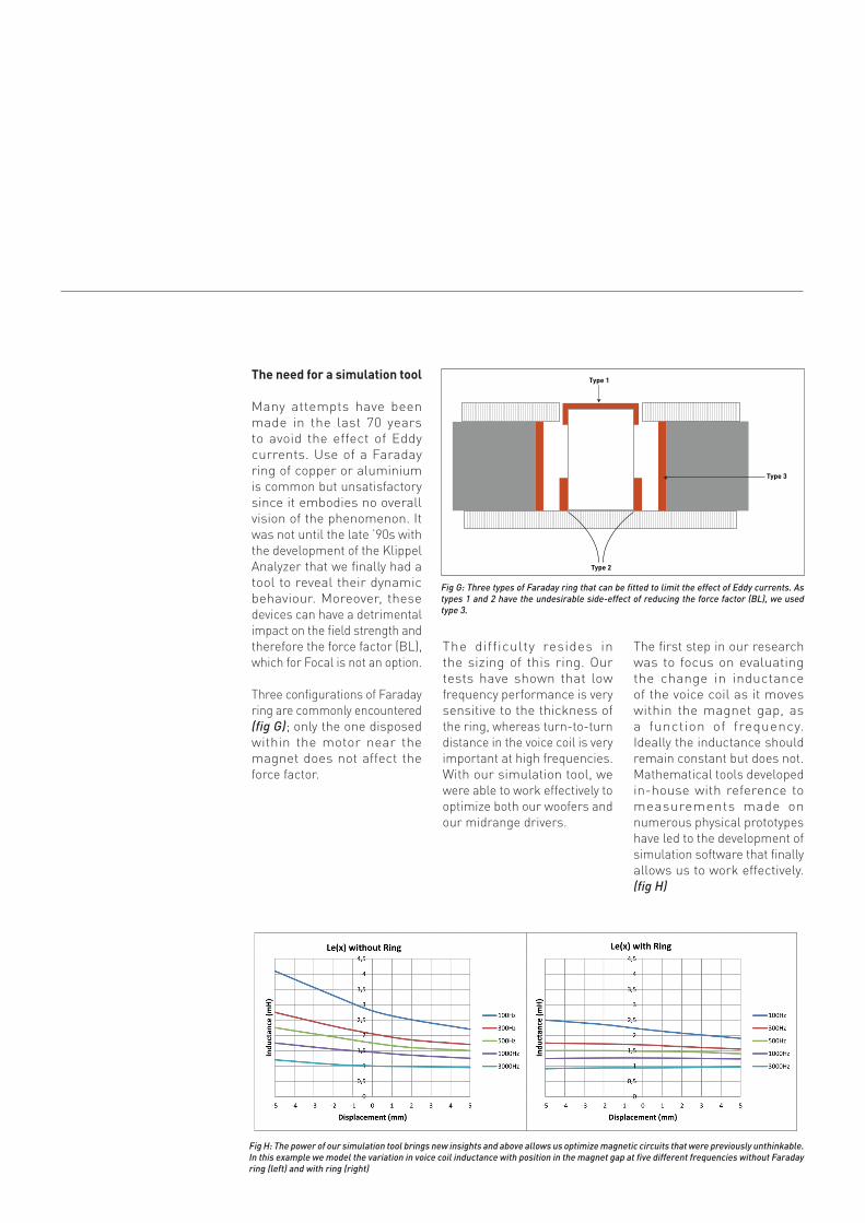
Fig G: Three types of Faraday ring that can be fitted to limit the effect of Eddy currents. As types 1 and 2 have the undesirable side-effect of reducing the force factor (BL), we used type 3.
Fig G : La puissance de notre outil de simulation nous apporte une vision nouvelle et surtout nous autorise des optimisation des circuits magnétiques inenvisageable auparavant. En exemple, cette modélisation montrant la variation de l’inductance de la bobine en fonction de sa position dans l’entrefer pour 5 fréquences différentes.
the need for a simulation tool
Many attempts have been made in the last 70 years to avoid the effect of Eddy currents. Use of a Faraday ring of copper or aluminium is common but unsatisfactory since it embodies no overall vision of the phenomenon. It was not until the late ’90s with the development of the Klippel Analyzer that we finally had a tool to reveal their dynamic behaviour. Moreover, these devices can have a detrimental impact on the field strength and therefore the force factor (BL), which for Focal is not an option.
Three configurations of Faraday ring are commonly encountered (fig G); only the one disposed within the motor near the magnet does not affect the force factor.
The difficulty resides in the sizing of this ring. Our tests have shown that low frequency performance is very sensitive to the thickness of the ring, whereas turn-to-turn distance in the voice coil is very important at high frequencies. With our simulation tool, we were able to work effectively to optimize both our woofers and our midrange drivers.
The first step in our research was to focus on evaluating the change in inductance of the voice coil as it moves within the magnet gap, as a function of frequency. Ideally the inductance should remain constant but does not. Mathematical tools developed in-house with reference to measurements made on numerous physical prototypes have led to the development of simulation software that finally allows us to work effectively. (fig H)
Fig H: The power of our simulation tool brings new insights and above allows us optimize magnetic circuits that were previously unthinkable. In this example we model the variation in voice coil inductance with position in the magnet gap at five different frequencies without Faraday ring (left) and with ring (right)
Type 1
Type 3
Type 2
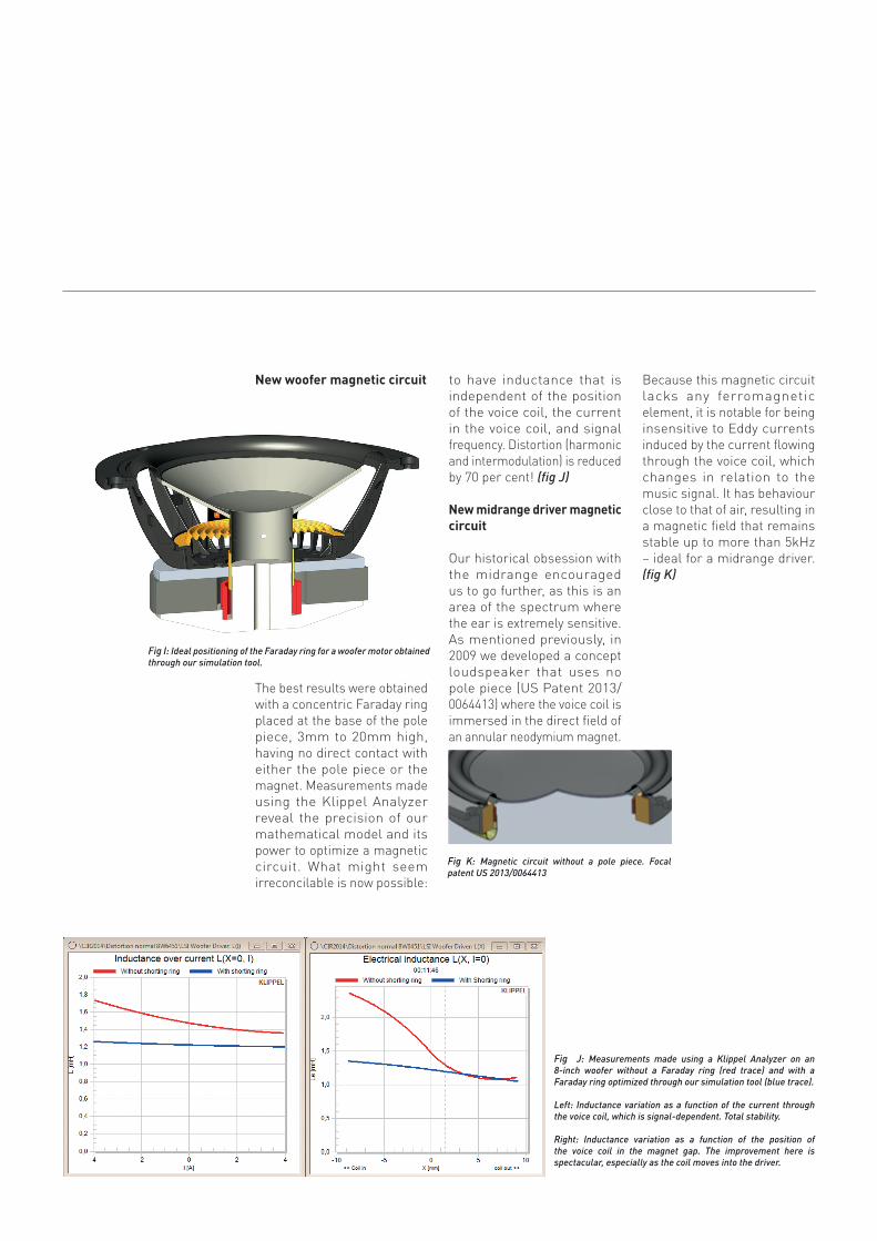
new woofer magnetic circuit
The best results were obtained with a concentric Faraday ring placed at the base of the pole piece, 3mm to 20mm high, having no direct contact with either the pole piece or the magnet. Measurements made using the Klippel Analyzer reveal the precision of our mathematical model and its power to optimize a magnetic circuit. What might seem irreconcilable is now possible:
to have inductance that is independent of the position of the voice coil, the current in the voice coil, and signal frequency. Distortion (harmonic and intermodulation) is reduced by 70 per cent! (fig J)
new midrange driver magnetic circuit
Our historical obsession with the midrange encouraged us to go further, as this is an area of the spectrum where the ear is extremely sensitive. As mentioned previously, in 2009 we developed a concept loudspeaker that uses no pole piece (US Patent 2013/ 0064413) where the voice coil is immersed in the direct field of an annular neodymium magnet.
Because this magnetic circuit lacks any ferromagnetic element, it is notable for being insensitive to Eddy currents induced by the current flowing through the voice coil, which changes in relation to the music signal. It has behaviour close to that of air, resulting in a magnetic field that remains stable up to more than 5kHz – ideal for a midrange driver. (fig K)
Fig I: Ideal positioning of the Faraday ring for a woofer motor obtained through our simulation tool.
Fig K: Magnetic circuit without a pole piece. Focal patent US 2013/0064413
Fig J: Measurements made using a Klippel Analyzer on an 8-inch woofer without a Faraday ring (red trace) and with a Faraday ring optimized through our simulation tool (blue trace).
Left: Inductance variation as a function of the current through the voice coil, which is signal-dependent. Total stability.
Right: Inductance variation as a function of the position of the voice coil in the magnet gap. The improvement here is spectacular, especially as the coil moves into the driver.
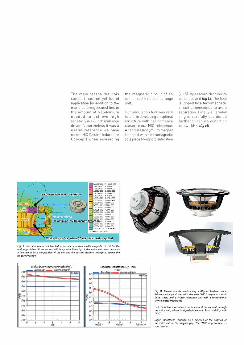
The main reason that this concept has not yet found application (in addition to the manufacturing issues) lies in the amount of Neodymium needed to achieve high sensitivity in a 6-inch midrange driver. Nevertheless it was a useful reference we have named NIC (Neutral Inductance Concept) when envisaging
the magnetic circuit of an economically viable midrange unit.
Our simulation tool was very helpful in developing an optimal structure with performance closer to our NIC reference. A central Neodymium magnet is topped with a ferromagnetic pole piece brought to saturation
(> 1.5T) by a second Neodymium pellet above it (fig L). The field is looped by a ferromagnetic circuit dimensioned to avoid saturation. Finally a Faraday ring is carefully positioned further to reduce distortion below 1kHz. (fig M)
Fig M: Measurements made using a Klippel Analyzer on a 6-inch midrange driver with the new "NIC" magnetic circuit (blue trace) and a 6-inch midrange unit with a conventional ferrite motor (red trace).
Left: Inductance variation as a function of the current through the voice coil, which is signal-dependent. Total stability with "NIC".
Right: Inductance variation as a function of the position of the voice coil in the magnet gap. The “NIC” improvement is spectacular.
Fig L: Our simulation tool has led us to this optimized «NIC» magnetic circuit for the midrange driver. It reconciles efficiency with linearity of the voice coil inductance as a function of both the position of the coil and the current flowing through it, across the frequency range.
0,50
0,45
0,40
0,35
0,30
0,25
0,20
0,15
0,10
0,05
0,00-3 -2 -1 0 1 2 3
I [A]
L [m
H]
Inductance over current L (X=0, I)New design Electra Midrange
KLIPPEL 1,0
0,9
0,8
0,7
0,6
0,5
0,4
0,3
0,2
0,1
0,0-4 -2 0 2 4
L [m
H]
New design Electra MidrangeKLIPPEL
<< Coil in X [mm] Coil out >>
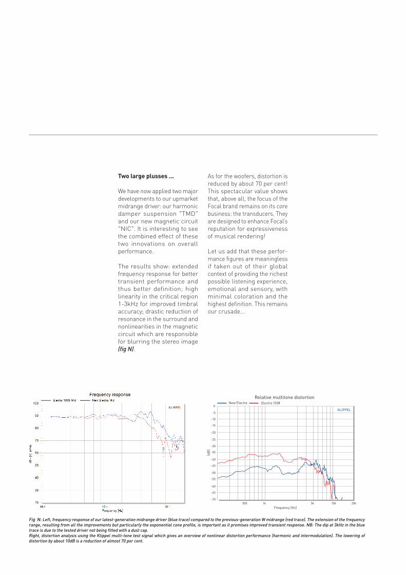
two large plusses ...
We have now applied two major developments to our upmarket midrange driver: our harmonic damper suspension "TMD" and our new magnetic circuit "NIC". It is interesting to see the combined effect of these two innovations on overall performance.
The results show: extended frequency response for better transient performance and thus better definition; high linearity in the critical region 1-3kHz for improved timbral accuracy; drastic reduction of resonance in the surround and nonlinearities in the magnetic circuit which are responsible for blurring the stereo image (fig N).
As for the woofers, distortion is reduced by about 70 per cent! This spectacular value shows that, above all, the focus of the Focal brand remains on its core business: the transducers. They are designed to enhance Focal’s reputation for expressiveness of musical rendering!
Let us add that these perfor-mance figures are meaningless if taken out of their global context of providing the richest possible listening experience, emotional and sensory, with minimal coloration and the highest definition. This remains our crusade...
Fig N: Left, frequency response of our latest-generation midrange driver (blue trace) compared to the previous-generation W midrange (red trace). The extension of the frequency range, resulting from all the improvements but particularly the exponential cone profile, is important as it promises improved transient response. NB: The dip at 3kHz in the blue trace is due to the tested driver not being fitted with a dust cap.Right, distortion analysis using the Klippel multi-tone test signal which gives an overview of nonlinear distortion performance (harmonic and intermodulation). The lowering of distortion by about 10dB is a reduction of almost 70 per cent.
0
-5
-10
-15
-20
-25
-30
-35
-40
-45
-50
-55
-60
-65
-70
[dB
]
500 1k 5k 10k 20kFrequency [Hz]
Relative multitone distortionNew Electra Electra 1038
KLIPPEL
From 2008 to 2010 Utopia III defined our latest thoughts on magnetic design (EM/IAL2) and the side effects caused by the suspensions of our W sandwich cones (woofer midrange Diablo Utopia). Four years later we have developed solutions applicable to models that will reach a wider audience. Innovation continues, enriched by the arrival of new talent, which is what we like to do at Focal.
Like the research leading to the Flax sandwich cones introduced in the Aria range in 2013, innovation downwards takes its meaning!We further confirm that we have also always had an undeniable technological leadership with
our latest developments Sandwich W. Along with the Beryllium for tweeter cone. That is reassuring.
It is part of our brand identity, as mentioned in the introduction, that exploration and pragmatism are not incompatible. On the contrary, they complement each other surprisingly well.
In Utopia we have a flagship range, globally recognized, selective in nature and which therefore excludes many consumers. This is characteristic of exceptional products. Its move down-market makes no sense – it’s not possible because it would no longer be Utopia.
By contrast, improving the premium segment occupied by Electra using new technologies inspired by what we have learned from Utopia III makes perfect sense. The jump in performance is spectacular...
SOPRA, A ShOwCASE FOR thESE tEChnOlOgiCAl
ADvAnCES
Compactness, strength, innovation ; these are some of the many terms which, from the beginning, have fuelled our design brief for Sopra. The first sketches soon took shape by integrating the key "focus time" element of the brand image. The tweeter remains central, the "eye" of the product that captures the eye of the onlooker. Its positioning is highly critical as it predetermines the speaker’s spatiality.
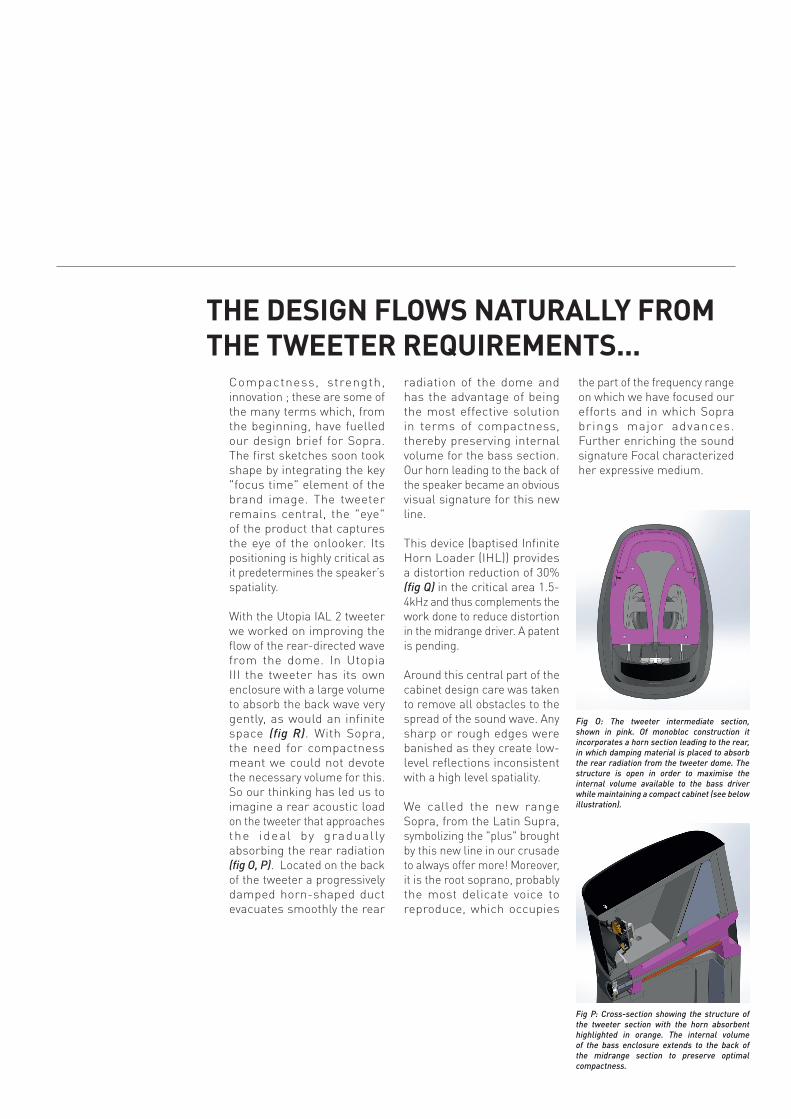
With the Utopia IAL 2 tweeter we worked on improving the flow of the rear-directed wave from the dome. In Utopia III the tweeter has its own enclosure with a large volume to absorb the back wave very gently, as would an infinite space (fig R). With Sopra, the need for compactness meant we could not devote the necessary volume for this. So our thinking has led us to imagine a rear acoustic load on the tweeter that approaches the ideal by gradually absorbing the rear radiation (fig O, P). Located on the back of the tweeter a progressively damped horn-shaped duct evacuates smoothly the rear
radiation of the dome and has the advantage of being the most effective solution in terms of compactness, thereby preserving internal volume for the bass section. Our horn leading to the back of the speaker became an obvious visual signature for this new line.
This device (baptised Infinite Horn Loader (IHL)) provides a distortion reduction of 30% (fig Q) in the critical area 1.5-4kHz and thus complements the work done to reduce distortion in the midrange driver. A patent is pending.
Around this central part of the cabinet design care was taken to remove all obstacles to the spread of the sound wave. Any sharp or rough edges were banished as they create low-level reflections inconsistent with a high level spatiality.
We called the new range Sopra, from the Latin Supra, symbolizing the "plus" brought by this new line in our crusade to always offer more! Moreover, it is the root soprano, probably the most delicate voice to reproduce, which occupies
the part of the frequency range on which we have focused our efforts and in which Sopra brings major advances. Further enriching the sound signature Focal characterized her expressive medium.
thE DESign FlOwS nAtURAllY FROM thE twEEtER REQUiREMEntS...
Fig O: The tweeter intermediate section, shown in pink. Of monobloc construction it incorporates a horn section leading to the rear, in which damping material is placed to absorb the rear radiation from the tweeter dome. The structure is open in order to maximise the internal volume available to the bass driver while maintaining a compact cabinet (see below illustration).
Fig P: Cross-section showing the structure of the tweeter section with the horn absorbent highlighted in orange. The internal volume of the bass enclosure extends to the back of the midrange section to preserve optimal compactness.
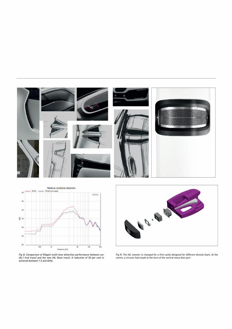
Fig Q: Comparison of Klippel multi-tone distortion performance between our IAL1 (red trace) and the new IHL (blue trace). A reduction of 30 per cent is achieved between 1.5 and 4kHz.
Fig R: The IAL tweeter is changed for a first cavity designed for different density foam. At the centre, a circular hole leads to the horn of the central mono bloc part.
The first listening assessment, made in mid-July 2014 and conducted with prototypes of the midrange driver incorporating the magnetic and mechanical innovations, were outstanding. The quasi "holographic" quality of vocals could not have been more encouraging, as were focus, articulation, expression ; in short, a surprising realism.
Beginning in November 2014, the first tuning sessions began with transducers and cabinet in their completed forms to finalize crossover filtering. Sopra 2 was chosen as the reference point because it is the most complicated product for fine tuning. With a high-midrange-class all the difficulty lies in the connection of the serious track / lower midrange. The compactness sought on Sopra 2 imposes limits in the low range in one
hand, but especially in the other transitional arrangements to have the "fitting" the most successful in harmonic structure. In other words, to have the most accurate height and amplitude of each vis-à-vis the original musical message harmonics according reproduced by the serious way or through a medium. In the past the complexity of tuning mainly resided at connection upper midrange. Having set the source limitations (end band of the medium through TMD and tweeter BOT with IHL) has significantly simplified the upper midrange filtering and naturally moved the issue to the serious connection medium.
By early December we had versions of Sopra 2 that we could evaluate with different electronics and in various acoustics. Its incredibly neutral, natural, high-definition sound
and high-midrange spatiality revealed that the speakers have extreme sensitivity to other components in the system. This point certainly very positive, but requires a particular discipline when tuning not to compensate for faults upstream of the speaker. We had to redouble our efforts and try endless combinations to achieve near-final definition of Sopra 2 by mid-February.
liStEning AnD tUning
Gérard ChrétienFebruary 12th 2015

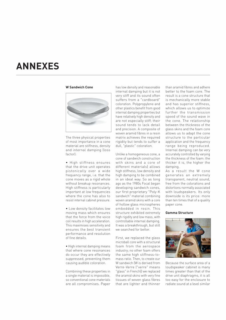
w Sandwich Cone
The three physical properties of most importance in a cone material are stiffness, density and internal damping (loss factor):
• High stiffness ensures that the drive unit operates pistonically over a wide frequency range, i.e. that the cone moves as a rigid whole without breakup resonances. High stiffness is particularly important at low frequencies where the cone has also to resist internal cabinet pressure.
• Low density facilitates low moving mass which ensures that the force from the voice coil results in high acceleration. This maximises sensitivity and ensures the best transient performance and resolution of fine details.
• High internal damping means that where cone resonances do occur they are effectively suppressed, preventing them causing audible coloration.
Combining these properties in a single material is impossible, so conventional cone materials are all compromises. Paper
has low density and reasonable internal damping but it is not very stiff and its sound often suffers from a "cardboard" coloration. Polypropylene and other plastics benefit from good internal damping properties but have relatively high density and are not especially stiff; their sound tends to lack detail and precision. A composite of woven aramid fibres in a resin matrix achieves the required rigidity but tends to suffer a dull, "plastic" coloration.
Unlike a homogeneous cone, a cone of sandwich construction with skins and a core of different materials) allows high stiffness, low density and high damping to be combined in an ideal way. So as long ago as the 1980s Focal began developing sandwich cones, our first proprietary "Poly-K sandwich" material combining woven aramid skins with a core of hollow glass microspheres embedded in resin. This structure exhibited extremely high rigidity and low mass, with controllable internal damping. It was a breakthrough, but still we searched for better.
First, we replaced the glass microball core with a structural foam from the aerospace industry; no other foam offers the same high stiffness-to-mass ratio. Then, to create our W sandwich (W is derived from Verre-Verre ("verre" means "glass" in French)) we replaced the aramid skins with very fine tissues of woven glass fibres that are lighter and thinner
than aramid fibres and adhere better to the foam core. The result is a cone structure that is mechanically more stable and has superior stiffness, which allows us to optimize further the transmission speed of the sound wave in the cone. The relationship between the thickness of the glass skins and the foam core allows us to adapt the cone structure to the particular application and the frequency range being reproduced. Internal damping can be very accurately controlled by varying the thickness of the foam: the thicker it is, the higher the damping.As a result the W cone generates an extremely transparent, neutral sound, free from the colorations and distortions normally associated with loudspeakers. Its only downside is its price: more than ten times that of a quality paper cone.
gamma Structure
Because the surface area of a loudspeaker cabinet is many times greater than that of the drive unit diaphragms, it is all too easy for the enclosure to radiate sound at a level similar
AnnEXES
to that of the drivers, sound that is coloured by resonances within the cabinet structure. This muddies the speaker’s sound and blurs the stereo image.
To prevent this, it is vital that the loudspeaker cabinet be as inert as possible. At Focal, we use MDF (medium-density fibreboard) to achieve this. It may seem a "low-tech" solution compared to some cabinet materials employed today but MDF has inherent advantages that we believe make it the optimum material from which to construct a loudspeaker.
First, it is dense enough and stiff enough – when used in a thick, heavy front baffle – to resist the magnet reaction force from the drive units. As the driver diaphragm is forced forwards by the voice coil, an equal force acts in the opposite direction on the drive unit chassis. This is one of the major inputs of vibrational energy to the cabinet and it must be resisted. This requires not just a thick baffle but also meticulously placed internal bracing. Too stiff a cabinet, though, can be as bad as one which is not stiff enough because it pushes structural resonances up in frequency to a part of the spectrum where the ear is more sensitive.
Second, MDF has something resembling a sandwich structure, in which the faces on each side of the board are denser than its core. As well as
contributing to stiffness, this endows MDF with good internal damping to help suppress vibrations when they occur.Sopra and Utopia front baffles use MDF plates thick laminated to multiply the sandwich effect (69mm thick for Sopra).
Third, MDF can easi ly formed into curved cabinet forms. These are good both acoustically, because they allow the radiated sound to diffract smoothly around the cabinet without secondary radiation from sharp cabinet edges, and structurally because curved panels are stiffer than conventional flat ones.This combination of a thick front baffle, extensive internal bracing and curved panel forms (all constructed using MDF) we call Focal’s Gamma Structure. It is as important to the sound of our top loudspeakers as the drive units themselves.
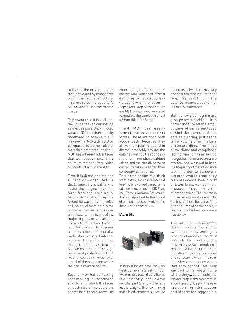
iAl & ihl
In beryllium we have the very best dome material for our tweeter. Because of beryllium’s low densi ty the dome weighs just 21mg – literally featherweight. This low moving mass is advantageous because
it increases tweeter sensitivity and ensures excellent transient response, resulting in the detailed, nuanced sound that is Focal’s trademark.
But the low diaphragm mass also poses a problem. In a conventional tweeter a small volume of air is enclosed behind the dome, and this acts as a spring, just as the larger volume of air in a bass enclosure does. The mass of the dome and compliance (springiness) of the air behind it together form a resonance system, and we need to keep the frequency of that resonance low in order to achieve a tweeter whose frequency response extends down to 2kHz or lower, to allow an optimum crossover frequency to the midrange driver. The low mass of the beryllium dome works against us here because, for a given volume of enclosed air, it results in a higher resonance frequency.
The solution is to increase the volume of air behind the tweeter dome by venting its rear radiation into a chamber behind. That solves the moving mass/air compliance resonance issue but it is vital that standing wave resonances and reflections within the rear chamber are suppressed so that they cannot find their way back to the tweeter dome where they would muddy its forward output and compromise sound quality. Ideally, the rear radiation from the tweeter should seem to disappear into
an infinite acoustic space, from where it never returns.
To achieve this requires careful design of the rear chamber and meticulous application of sound absorbent materials within it. This is what we achieved with IAL (Infinite Acoustic Loading) first used in the Electra 1000 Be series. In IAL 2, used in Utopia, we further refined this concept by improving the flow of sound from the rear of the tweeter dome into the absorbent chamber. But this solution takes up a lot of space, more than was available to us for Sopra. So we developed Infinite Horn Loader (IHL) to achieve equally effective absorption of the rear radiation but in a smaller volume.
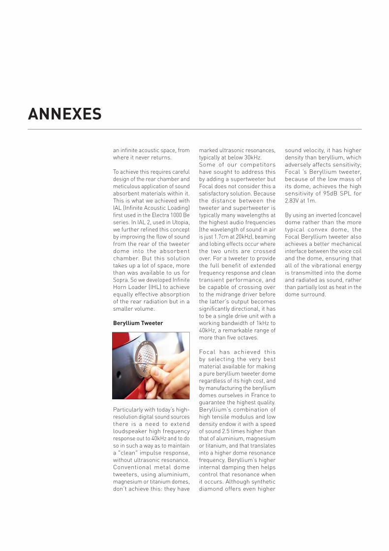
Beryllium tweeter
Particularly with today’s high-resolution digital sound sources there is a need to extend loudspeaker high frequency response out to 40kHz and to do so in such a way as to maintain a "clean" impulse response, without ultrasonic resonance. Conventional metal dome tweeters, using aluminium, magnesium or titanium domes, don’t achieve this: they have
marked ultrasonic resonances, typically at below 30kHz.Some of our competitors have sought to address this by adding a supertweeter but Focal does not consider this a satisfactory solution. Because the distance between the tweeter and supertweeter is typically many wavelengths at the highest audio frequencies (the wavelength of sound in air is just 1.7cm at 20kHz), beaming and lobing effects occur where the two units are crossed over. For a tweeter to provide the full benefit of extended frequency response and clean transient performance, and be capable of crossing over to the midrange driver before the latter’s output becomes significantly directional, it has to be a single drive unit with a working bandwidth of 1kHz to 40kHz, a remarkable range of more than five octaves.
Focal has achieved this by selecting the very best material available for making a pure beryllium tweeter dome regardless of its high cost, and by manufacturing the beryllium domes ourselves in France to guarantee the highest quality. Beryllium’s combination of high tensile modulus and low density endow it with a speed of sound 2.5 times higher than that of aluminium, magnesium or titanium, and that translates into a higher dome resonance frequency. Beryllium’s higher internal damping then helps control that resonance when it occurs. Although synthetic diamond offers even higher
sound velocity, it has higher density than beryllium, which adversely affects sensitivity; Focal ’s Beryllium tweeter, because of the low mass of its dome, achieves the high sensitivity of 95dB SPL for 2.83V at 1m.
By using an inverted (concave) dome rather than the more typical convex dome, the Focal Beryllium tweeter also achieves a better mechanical interface between the voice coil and the dome, ensuring that all of the vibrational energy is transmitted into the dome and radiated as sound, rather than partially lost as heat in the dome surround.
AnnEXES

Focal-JMlab® - BP 374 - 108, rue de l’Avenir - 42353 La Talaudière cedex - France. Tél . 33 (0) 477 435 700 - Fax +33 (0) 477 376 587 - © 2013 Focal-JMlab® - SCEB -140327/1
Due to constant technological advances, Focal-JMlab® reserves its right to modify specifications without notice. - Images may not conform exactly to specific product - Photos L’Atelier Sylvain Madelon