Embed Size (px)
Citation preview

Southern International Professional Engineering6015 Chester Circle, Suite #210 Jacksonville, FL 32217Phone: +1 904-379-0944Email: [email protected]
OFFERING STANDARDAND CUSTOMIZED
LIFTING PRODUCTSFOR ANY APPLICATION
T H E R I G H T C O M P A N Y W H E N Y O U N E E D A L I F T
BETTER PRICING QUICK DELIVERY CUSTOMIZED PRODUCTS
INDUSTRY APPLICATIONS
LIFTING AND SPREADER BEAMS
C – HOOKS/COIL LIFTERS
ROLL & PALLET LIFTERS
BULK BAG & DRUM LIFTERS
FORKLIFT ATTACHMENTS
TONGS AND CLAMPS
• Steel Fabrication
• Material Handling
• Manufacturing
• Offshore
• Petroleum
• Highway
• Construction
• Shipping
• Rail
• Aerospace
• Power Plants
• Foundries
• Pulp/Paper
• Utilities
• Marine
• Civil
• Military
• Agricultural
• Wind
• Nuclear
• Automotive
• Crane/Hoists
cover
back cover
Summary Of Company Services• Standard Lifting Product Line
• Custom Lifting Products
• Product Support
• Civil, Mechanical & Structural Consulting
• Engineering Services
• On-site Evaluations
CATALOG NO. SIPE0617

SOUTHERN INTERNATIONAL PROFESSIONAL ENGINEERING CAN ENGINEER A SOLUTION TO YOUR LIFTING REQUIREMENTSWhen you need a qualified resource to assist with your manufacturing or lifting requirements, SIPE is the company you turn to. We are a minority-owned business staffed by licensed professional engineers with over 80 years of experience offering a full line of standard and customized lifting products and automated production tools. No job is too difficult or unusual because our experience includes work in a broad variety of Industry segments. Whether you need the lifting device or just the lifting analysis and plan, SIPE is the right choice.
We specialize in designs and products made to customer
specifications and particular job applications. Producing superior lifting devices and designs by experienced American professional engineers and craftsmen, supported by a responsive, friendly and accessible customer service team is the core of who we are.
Our product potential and capabilities extend far beyond the selections offered in this catalog. If you don’t see what you need, simply give us a call or fill out the RFQ form on page 13 and email it to us. We will gladly quote it for you in a timely manner. We understand that response time wins orders and delivery time wins customers!
PRODUCT WARRANTYSouthern International Professional Engineering, L.L.C. (SIPE) is incorporated in Florida, with offices at 6015 Chester Avenue,
Suite 210, Jacksonville, FL 32217. SIPE is the “Warrantor” of the product manufactured under its namesake. The warranty includes all workmanship in the manufacture, assembly and packaging of its finished products. Unless stated otherwise,
all SIPE products are given a warranty period not to exceed two (2) years from the date of delivery to the customer.
Southern International Professional Engineering has herein set forth in conspicuous language an exclusion of any warranty either expressed or implied, which is not specifically and particularly contained herein. Please refer to that statement for
representations and warranties of products manufactured by Southern International Professional Engineering.
THE WARRANTY IS VALID DURING THE WARRANTY PERIOD, WITH THE FOLLOWING CONDITIONS1) At the sole discretion of the Warrantor, this warranty will replace or repair any SIPE product declared defective due to materials or workmanship at no cost to the customer.
2) Warranty is voided should the product be operated beyond that which is stated in the operations manual, or the product is abused or not maintained.
3) Defects must be declared within the warranty period.
4) Written notice of any defect must be sent to SIPE via certified mail within the warranty period.
5) Customer is responsible for shipment costs, should the product be repaired or replaced by SIPE.
6) Customer must acquire a material return authorization (MRA) prior to returning any SIPE product. The product nameplate/identifier must be intact and readable for product verification.
7) Warranty is non-transferable.
6015 Chester Circle, Suite #210 Jacksonville, FL 32217Phone: +1 904-379-0944Email: [email protected]
ALL PRODUCTS ARE CODE COMPLIANTSIPE is compliant with ASME, AISC, AISI, ASTM, AWS, NEC, NEMA, OSHA, and SAE Codes.
We proudly comply with the Presidential Executive Order and Federal Trade Commission requirements for the “Produced in the United States” designation.
NOTICE OF EXCLUSION OF WARRANTY
PRODUCED IN THE UNITED STATES

2
SIPE DESIGN CRITERIA
OTHER SIPE CRITERIA
CUSTOMER CRITERIA
n The ASME BTH-1 Standard addressing the structural and mechanical design criteria for below-the-hooking lifting devices. Unless otherwise specified, all SIPE devices are designed using Design Category B and Service Class 2.
n The ASME B30.20 Standard pertaining to the fabrication, testing, inspection, installation, operation and maintenance of Lifting, Material Handling and below-the-hook Devices.
n AWS (welding) per D14.1 is followed for joint design as required in this design specification.
n AISC is followed for member sizing and structural analysis approaches. All bolted joints and welding criteria are also addressed within this code.
n Where special analysis is required, recognized texts and classical analysis techniques will be used.
n SIPE provides an operating manual defining the proper use and limitations associated with each product.
n All materials shall meet A36 or A572 GR. 50, A500 GR.B and A513 steel strength. Certification sheets are supplied with all material used.
n Welding is performed with certified welders using E90 or better electrode.
n All designs are backed up with a complete analysis that is kept on file at SIPE.
n A safe, high quality product is the primary design objective ensuring years of service.
n All materials and labor are “Produced in the United States” and meet Federal Trade Commission rules for made in USA content.
n Fill out and email the RFQ Form on page 13 to [email protected] to assist in an efficient quoting process.
n Capacity and basic dimensions to be provided. All special loading or lifting conditions shall be noted.
n Special interface (upper and lower) accessories and requirements shall be defined.
n Call us to discuss. Any and all job specific information up front that will assist in designing the correct tool for the job and minimize quoting delays.

1
Design Criteria ....................................................................................... Page 2
Lifting Beams (Fixed Position) ......................................................... Page 3
Spreader Beams (Fixed Position) ................................................... Page 4
Lifting & Spreader Beams (Adjustable) ....................................... Page 5
Beam Options & Specifications ...................................................... Page 6
C – Hooks/Coil Lifters ......................................................................... Page 7
Roll Lifters & Pallet Lifters ................................................................ Page 8
Bulk Bag Lifters & Drum Lifters ..................................................... Page 9
Forklift Attachments .......................................................................... Page 10
Lifting Tongs ........................................................................................... Page 11
Lifting Clamps ................................................................................ Page 12
Request for Quote (RFQ) ........................................................... Page 13
TABLE OF CONTENTS
Disclaimer: All product designs are subject to change without notice. Product pictures in this catalog are a representation of a specific design. The product you purchase will be designed for your specific application and may not look exactly like the picture in this catalog.
3
WH
HR
L
CAPACITY
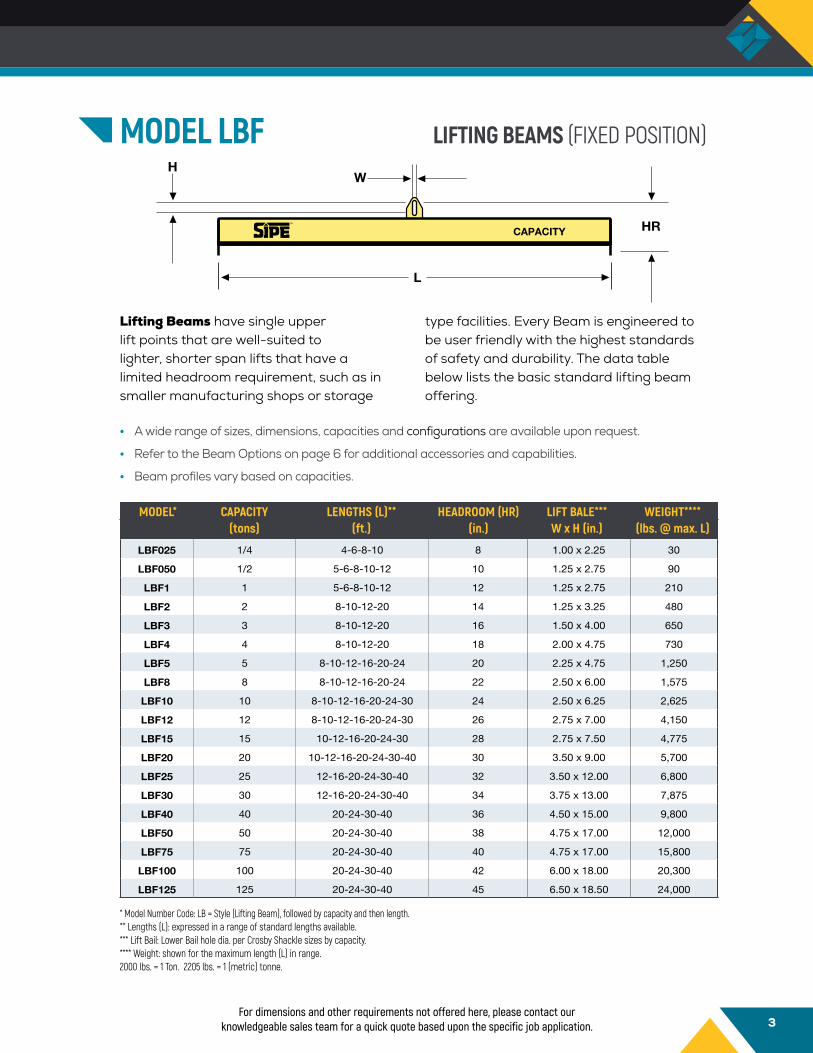
MODEL LBF LIFTING BEAMS (FIXED POSITION)
Lifting Beams have single upper lift points that are well-suited to lighter, shorter span lifts that have a limited headroom requirement, such as in smaller manufacturing shops or storage
type facilities. Every Beam is engineered to be user friendly with the highest standards of safety and durability. The data table below lists the basic standard lifting beam offering.
• A wide range of sizes, dimensions, capacities and configurations are available upon request.
• Refer to the Beam Options on page 6 for additional accessories and capabilities.
• Beam profiles vary based on capacities.
LBF025 1/4 4-6-8-10 8 1.00 x 2.25 30
LBF050 1/2 5-6-8-10-12 10 1.25 x 2.75 90
LBF1 1 5-6-8-10-12 12 1.25 x 2.75 210
LBF2 2 8-10-12-20 14 1.25 x 3.25 480
LBF3 3 8-10-12-20 16 1.50 x 4.00 650
LBF4 4 8-10-12-20 18 2.00 x 4.75 730
LBF5 5 8-10-12-16-20-24 20 2.25 x 4.75 1,250
LBF8 8 8-10-12-16-20-24 22 2.50 x 6.00 1,575
LBF10 10 8-10-12-16-20-24-30 24 2.50 x 6.25 2,625
LBF12 12 8-10-12-16-20-24-30 26 2.75 x 7.00 4,150
LBF15 15 10-12-16-20-24-30 28 2.75 x 7.50 4,775
LBF20 20 10-12-16-20-24-30-40 30 3.50 x 9.00 5,700
LBF25 25 12-16-20-24-30-40 32 3.50 x 12.00 6,800
LBF30 30 12-16-20-24-30-40 34 3.75 x 13.00 7,875
LBF40 40 20-24-30-40 36 4.50 x 15.00 9,800
LBF50 50 20-24-30-40 38 4.75 x 17.00 12,000
LBF75 75 20-24-30-40 40 4.75 x 17.00 15,800
LBF100 100 20-24-30-40 42 6.00 x 18.00 20,300
LBF125 125 20-24-30-40 45 6.50 x 18.50 24,000
MODEL* CAPACITY LENGTHS (L)** HEADROOM (HR) LIFT BALE*** WEIGHT**** (tons) (ft.) (in.) W x H (in.) (lbs. @ max. L)
For dimensions and other requirements not offered here, please contact our knowledgeable sales team for a quick quote based upon the specific job application.
* Model Number Code: LB = Style (Lifting Beam), followed by capacity and then length.** Lengths (L): expressed in a range of standard lengths available.*** Lift Bail: Lower Bail hole dia. per Crosby Shackle sizes by capacity. **** Weight: shown for the maximum length (L) in range.2000 lbs. = 1 Ton. 2205 lbs. = 1 (metric) tonne.

4
MODEL SBF
Spreader Beams efficiently distribute the weight of a load between two lifting points and are effective at lifting loads with large spans where headroom is not limited. They add a measure of stability and are ideal
for lifting heavy duty loads. Every Beam is engineered to be user friendly with the highest standards of safety and durability. The data table below lists the basic standard, fixed position, spreader beam offering.
For dimensions and other requirements not offered here, please contact our knowledgeable sales team for a quick quote based upon the specific job application.
* Model Number Code: SB = Style (Spreader Beams), followed by capacity and then length** Lengths: Shown in a range of standard lengths available.*** Lift Bales: Lifting holes for “Upper/Lower” sling rigging are based on Crosby® shackle sizes.**** Weight: Shown is for the maximum length (L) in the range.2000 lbs. = 1 Ton. 2205 lbs. = 1 (metric) tonne.
HR
L
CAPACITY
45˚45˚
• A wide range of sizes, dimensions, capacities and configurations are available upon request.• Refer to the Beam Options on page 6 for additional accessories and capabilities.• The actual spread of the lower Lugs will be slightly less than the length of the beam.• Designed for a 45˚ Sling Angle. 30˚ to 60˚ available on request.• Complies with ASME Standards.• Rigging available on request.
SBF025 1/4 4-6-8 57-5/8 0.313 / 0.313 40
SBF050 1/2 4-6-8 57-5/8 0.375 / 0.313 50
SBF1 1 4-6-8-10-12 86-7/16 0.500 / 0.375 65
SBF2 2 4-6-8-10-12 86-7/16 0.750 / 0.500 105
SBF3 3 8-10-12-16-20 144 1.000 / 0.625 300
SBF4 4 8-10-12-16-20 144 1.000 / 0.750 350
SBF5 5 10-12-16-20-24 172-3/4 1.125 / 0.875 425
SBF8 8 10-12-16-20-24-30 216 1.250 / 1.000 500
SBF10 10 12-16-20-24-30 216 1.375 / 1.000 575
SBF12 12 12-16-20-24-30 216 1.500 / 1.125 625
SBF15 15 16-20-24-30-40 288 1.750 / 1.250 950
SBF20 20 16-20-24-30-40 288 2.250 / 1.375 1,200
SBF25 25 16-20-24-30-40 288 2.250 / 1.500 1,250
SBF30 30 16-20-24-30-40 288 2.500 / 1.750 1,325
SBF40 40 16-20-24-30-40 288 3.000 / 2.250 1,400
SBF50 50 16-20-24-30-40 288 3.000 / 2.250 1,500
MODEL* CAPACITY LENGTHS (L)** HEADROOM (HR) LIFT BALES*** WEIGHT**** (tons) (ft) (in.) (hole dia.) (in.) (lbs. @ max. L)
SPREADER BEAMS (FIXED POSITION)
5
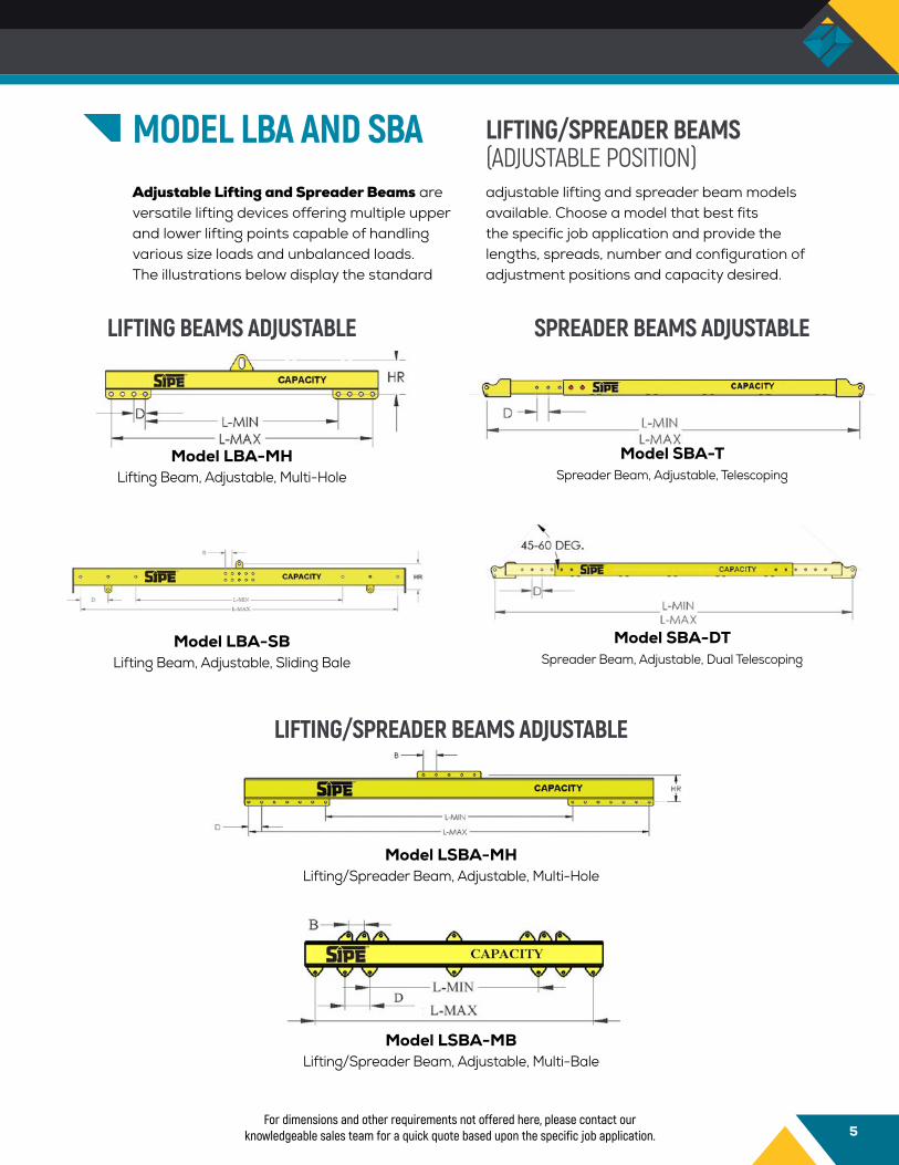
MODEL LBA AND SBAAdjustable Lifting and Spreader Beams are versatile lifting devices offering multiple upper and lower lifting points capable of handling various size loads and unbalanced loads. The illustrations below display the standard
adjustable lifting and spreader beam models available. Choose a model that best fits the specific job application and provide the lengths, spreads, number and configuration of adjustment positions and capacity desired.
For dimensions and other requirements not offered here, please contact our knowledgeable sales team for a quick quote based upon the specific job application.
LIFTING/SPREADER BEAMS (ADJUSTABLE POSITION)
SPREADER BEAMS ADJUSTABLE
Model SBA-TSpreader Beam, Adjustable, Telescoping
Model SBA-DTSpreader Beam, Adjustable, Dual Telescoping
LIFTING BEAMS ADJUSTABLE
Model LBA-MHLifting Beam, Adjustable, Multi-Hole
Model LBA-SBLifting Beam, Adjustable, Sliding Bale
LIFTING/SPREADER BEAMS ADJUSTABLE
Model LSBA-MHLifting/Spreader Beam, Adjustable, Multi-Hole
Model LSBA-MBLifting/Spreader Beam, Adjustable, Multi-Bale
6
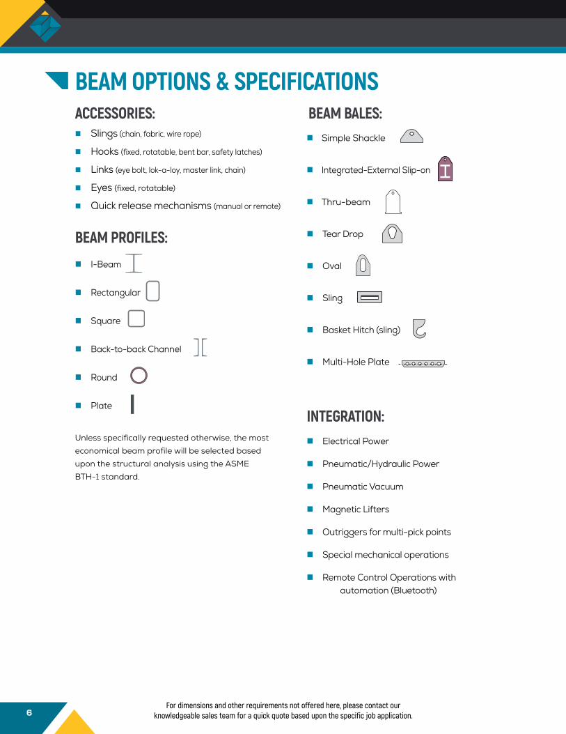
BEAM OPTIONS & SPECIFICATIONSBEAM BALES:
Unless specifically requested otherwise, the most economical beam profile will be selected based upon the structural analysis using the ASME BTH-1 standard.
n Simple Shackle
n Integrated-External Slip-on
n Thru-beam
n Tear Drop
n Oval
n Sling
n Basket Hitch (sling)
n Multi-Hole Plate
INTEGRATION:n Electrical Power
n Pneumatic/Hydraulic Power
n Pneumatic Vacuum
n Magnetic Lifters
n Outriggers for multi-pick points
n Special mechanical operations
n Remote Control Operations with automation (Bluetooth)
ACCESSORIES:n Slings (chain, fabric, wire rope)
n Hooks (fixed, rotatable, bent bar, safety latches)
n Links (eye bolt, lok-a-loy, master link, chain)
n Eyes (fixed, rotatable)
n Quick release mechanisms (manual or remote)
BEAM PROFILES:n I-Beam
n Rectangular
n Square
n Back-to-back Channel
n Round
n Plate
For dimensions and other requirements not offered here, please contact our knowledgeable sales team for a quick quote based upon the specific job application.

7
MODEL CH
C-Hooks are designed to lift and manipulate coils that are laying where the bore is horizontal to the ground. The data table below lists the basic standard style C-Hooks. For styles or
configurations not offered here, contact our knowledgeable and friendly sales team for a timely quote.
• Cut from high strength, low alloy steel plate.
• Counterweighted to remain level when loading and unloading.
• Stress relieving Corner Radii strategically placed to maximize service life.
• Beveled Lifting Arm to minimize potential coil damage.
• Tapered end for ease of entry into the coil I.D.
• Safety Curved Guide Handle assists in insertion and removal.
• Storage racks, Saddles, end stops and replaceable wear pads are available upon request.
C - HOOKS/COIL LIFTERS
For dimensions and other requirements not offered here, please contact our knowledgeable sales team for a quick quote based upon the specific job application.
OPTIONS
CH025-36-36 1/4 36 36 48 3/4 1-1/4 3 1/2 18 168CH050-48-48 1/2 48 48 60 1 1-1/4 3 1/2 24 354CH075-60-60 3/4 60 60 72 1-1/2 1-1/4 3 3/4 30 412CH1-48-60 1 48 60 72 1-1/2 1-1/4 3-1/2 1 24 533CH1-60-60 1 60 60 72 1-1/2 1-1/4 3-1/2 1 30 716
CH1.5-48-48 1-1/2 48 48 60 2 1-1/4 4 1 24 941CH1.5-60-60 1-1/2 60 60 72 2 1-1/4 4 1 30 1028CH2-48-48 2 48 48 60 2 1-1/2 4 1-1/4 24 1207CH2-60-60 2 60 60 72 2 1-1/2 4 1-1/4 30 1324CH3-48-48 3 48 48 60 3 1-1/2 5 1-1/2 24 1811CH3-60-60 3 60 60 62 3 1-3/4 5 1-1/2 30 1986CH5-60-60 5 60 60 75 4 2 6 1-1/2 30 3198CH8-72-72 8 72 72 85 4 2-1/4 6-1/2 1-1/2 30 5066
MODEL CAPACITY ARM TH HR T W H t CG WEIGHT (tons) (in.) (in.) (in.) (in.) (in.) (in.) (in.) (in.) (lbs.)

8
MODEL RLFFixed position Roll Lifters are designed to safely lift rolls by securely hooking onto the mandrel that runs through the I.D. of the roll. Provide capacity, dimensions L, C, & D, along with the crane hook capacity (used to calculate bale size) or crane hook dimensions for Lifter sizing and quoting. Adjustable width, pivoting arms and many other designs are available by request.
• Ideal for limited headroom applications.
• Fail-safe design on Lift Arm and Bail.
ROLL LIFTERS
MODEL PLF
MODEL PBL
Pallet Lifters offer the ability to lift and move pallets with a crane in applications where a forklift or pallet jack are not available or capable. The data table below illustrates the basic standard style Pallet Lifter, Fixed Position. Other adjustable position models can be quoted per specific job application requirement. Simply call out the fork spreads, service height, capacity, adjustability features and/or any other option desired for a timely quote.
• Remains level when unloaded.
• Safety Curved Guide Handle assists in insertion and removal.
• Tapered fork ends for ease of operation.
PALLET LIFTERS
PALLET BAR LIFTERS
For dimensions and other requirements not offered here, please contact our knowledgeable sales team for a quick quote based upon the specific job application.
Pallet Bar Lifters are a simple and inexpensive method of attaching standard 48” x 48” pallets to cranes. By sliding the Bars into the pallet and attaching slings to each end, the pallet can be easily and safely hoisted and manipulated. When not in use, they require minimal storage space.
Adjustable arm width design
(optional)
PBL1 1
PBL2 2
PBL2.5 2-1/2
MODEL CAPACITY (tons)
PLF1 1 42 36 50 66 24 2 1-1/4 2-1/2PLF2 2 42 36 50 68 24 2 1-3/4 2-3/4PLF3 3 42 36 50 72 24 2-1/2 2 3
MODEL CAPACITY L W C HR D T B H (tons) (in.) (in.) (in.) (in.) (in.) (in.) (in.) (in.)

9
MODEL BBL
MODEL DLS
Bulk Bag Lifters are designed to safely lift and manipulate bulk container bags. Construction consists of Rectangular Tube cross sections, a reinforced steel plate Main Connection with a fail-safe lift lug design and heavy duty safety latch hooks.
Single Drum Lifters are used to vertically lift and manipulate steel drums. The unlocked device is lowered around the exterior of the drum until the alignment stops bring it to rest just below the lip. By activating the cam locking arm a secure friction grip is created by squeezing as well as utilizing the lip of the drum as a built in catch.
• Minimizes headroom requirement• Safety latched hook connection system
• Fail-safe Pin Latch prevents accidental unlocking.
• Other designs, multiple Drum Lifters, Tilting and automated designs available upon request.
• Optional Model DLT illustrated to the right.
BULK BAG LIFTERS
DRUM LIFTERS
For dimensions and other requirements not offered here, please contact our knowledgeable sales team for a quick quote based upon the specific job application.
BBL050-36 1/2 36 8 50
BBL1-36 1 36 8 65
BBL1-42 1 42 8 98
BBL1.5-36 1-1/2 36 10 90
BBL2-36 2 36 10 115
BBL2-42 2 42 10 165
BBL2.5-48 2-1/2 48 12 190
MODEL CAPACITY L HR WEIGHT (tons) (in.) (in.) (lbs.)
Model BBL

10
MODEL FAForklift Attachments are devices designed to attach loads to forklifts for the purpose of efficiently lifting, manipulating and transporting. They make forklifts more versatile and are ideal for jobs where a crane is not available or practical. There are many different
style devices that fall into this category. Shown below is a sampling of popular attachments manufactured to customer specifications. For specific forklift attachment requests, please contact our knowledgeable and friendly sales team for a timely quote.
FORKLIFT ATTACHMENTS
Model FA-RCHForklift Attachment Rotating C-Hook
For dimensions and other requirements not offered here, please contact our knowledgeable sales team for a quick quote based upon the specific job application.
Model FA-CLForklift Attachment Center Lift
Model FA-RPForklift Attachment Rail Car Puller
Model FA-LBForklift Attachment Lifting Beam

11
MODEL LTLifting Tongs are designed to securely grab and lift a variety of materials and shapes. They have many generic uses as well as a broad array of customized, job specific applications. Our standard gripping, pressure
and supporting type Tongs are displayed here. Other designs and styles are available by request. For a quote on standard or customized Tongs, simply contact our sales department and provide the specifications required.
LIFTING TONGS (GRIPPING, PRESSURE, SUPPORTING)
For dimensions and other requirements not offered here, please contact our knowledgeable sales team for a quick quote based upon the specific job application.
Model LTG-RLifting Tong Gripping
Round
Model LTS-EGLifting Tong Supporting
External Grab
Model LTP-IGLifting Tong Pressure
Internal Grab
Model LTP-EGQLifting Tong PressureExternal Grab Quad
Model LTP-ILifting Tong Pressure
Irregular
Model LTP-LSLifting Tong Pressure
Lateral Straight
Model LTP-LJLifting Tong Pressure
Lateral Jaw
GRIPPING TONG SUPPORTING TONG PRESSURE TONGS
PRESSURE TONGS

12
Vertical ScrewNon-Marring
MODEL LCLifting Clamps are used to create temporary lifting points on a wide variety of materials and shapes. They have many generic uses as well as a broad array of customized, job specific applications. Standard configurations are
shown below, however, any other conceivable design is available by request. For a quote on a standard or a customized clamp, simply contact our sales department and provide the specifications required.
LIFTING CLAMPS
For dimensions and other requirements not offered here, please contact our knowledgeable sales team for a quick quote based upon the specific job application.
VerticalSling Camming
Vertical/Horizontal ScrewRotating
HorizontalSoft MaterialNon-Marring
VerticalSoft MaterialNon-Marring
Vertical ScrewGuide Set

13
SPECIFICATION ORDER FORM
SPECIFICATIONS
SKETCH
Dimensions (in.)ABCDHWT
CRANE HOOK DATA
RFQ FORM
Type of Tool: ___________________________________________________________________________________
Capacity:___________________________________ Estimated Cycles per day: ___________________________
Load Description: _______________________________________________________________________________
Operation Description: __________________________________________________________________________
Dimensions of Load: _____________________________________________________________________________
Orientation of Load: _____________________________________________________________________________
Number of pick up points: ________________________________________________________________________
Spacing between pickup points: ___________________________________________________________________
Minimum: O.D. _________________________ I.D. __________________Height/Width ____________________
Maximum: O.D. _________________________ I.D. __________________Height/Width ____________________
Automation: ___________________________________________________________________________________
Load Attachement (Shackles, Hooks, Slings, Other): ________________________________________________
Additional Information: _________________________________________________________________________
Contact: ________________________________________ Company name:_______________________________
Address:_________________________________ City: _________________ State:________Zip: _____________
Phone: __________________________________ Email: ____________________________
T W
H
LATCH OPEN
C B
A
D

Southern International Professional Engineering6015 Chester Circle, Suite #210 Jacksonville, FL 32217Phone: +1 904-379-0944Email: [email protected]
OFFERING STANDARDAND CUSTOMIZED
LIFTING PRODUCTSFOR ANY APPLICATION
T H E R I G H T C O M P A N Y W H E N Y O U N E E D A L I F T
BETTER PRICING QUICK DELIVERY CUSTOMIZED PRODUCTS
INDUSTRY APPLICATIONS
LIFTING AND SPREADER BEAMS
C – HOOKS/COIL LIFTERS
ROLL & PALLET LIFTERS
BULK BAG & DRUM LIFTERS
FORKLIFT ATTACHMENTS
TONGS AND CLAMPS
• Steel Fabrication
• Material Handling
• Manufacturing
• Offshore
• Petroleum
• Highway
• Construction
• Shipping
• Rail
• Aerospace
• Power Plants
• Foundries
• Pulp/Paper
• Utilities
• Marine
• Civil
• Military
• Agricultural
• Wind
• Nuclear
• Automotive
• Crane/Hoists
cover
back cover
Summary Of Company Services• Standard Lifting Product Line
• Custom Lifting Products
• Product Support
• Civil, Mechanical & Structural Consulting
• Engineering Services
• On-site Evaluations
CATALOG NO. SIPE0617