Embed Size (px)
DESCRIPTION
Installation Procedure 3DProjectionLensUnit3DProjectionLensUnit Projector Department Display Business Division B2B TableofContentsTableofContents Projector Department Display Business Division B2B Scope Projector Department Display Business Division B2B Flat Flat Flat Flat 1998pixel 1080pixel 1080pixel 1080pixel 1080pixel 1080pixel 858pixel l
Citation preview

3D Projection Lens Unit3D Projection Lens Unit
Installation Procedure
LKRL-A002(Wide Lens)
LKRL-A003(Tele Lens)
Projector Department Display Business Division B2B
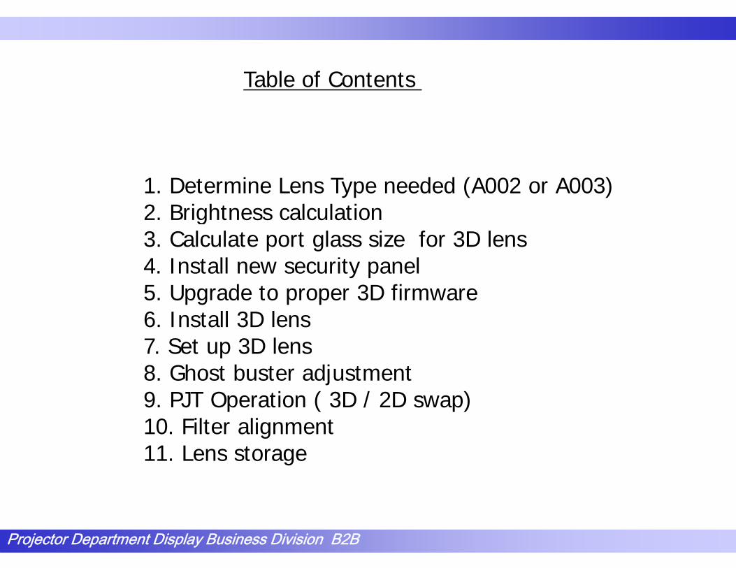
Table of ContentsTable of Contents
1. Determine Lens Type needed (A002 or A003)2. Brightness calculation2. Brightness calculation3. Calculate port glass size for 3D lens4. Install new security panel5 U d 3D fi5. Upgrade to proper 3D firmware6. Install 3D lens7. Set up 3D lens7. Set up 3D lens8. Ghost buster adjustment9. PJT Operation ( 3D / 2D swap)10 Fil li10. Filter alignment11. Lens storage
Projector Department Display Business Division B2B

1. Spec out LKRL-A002 or A003
Overview of Scope/Flat Adjustment MethodLKRL-A002/A003 has no automated zoom / focus function (Manual only)Instead of optical zooming, with LKRL-A002/A003, projector scales images to adjust for flat and scope.j p
l
Side Masking Top-Bottom Maskingl1998pixel
Flat1080pixel Flat
1998pixel
1080pixelFlat1080pixel Flat1080pixel
1080pixel Scope 858pixelScope
Projector Department Display Business Division B2B2578pixel 2048 pixel

付加投影系迄 14880 4151.52セットフォルター迄 14880 3528 792
2. Brightness calculation / lamp selectionセットフォルタ 迄 14880 3528.792スクリーンゲイン迄 30444.48 7219.908432眼鏡AR迄 30444.48 5978.084182m 2̂ 202.1019218 123.4637407
SXRD _2D SXRD _Single_RealDD
Lum en 20000 20000Brightness(ft− L) 14 4.5
22.02 17.21InitialLam p P 80 80
Parameter;Initial Lam p P 80 80Panel area 100 31G ray-10 93 93Virtual W hite 90 90Norm alproj 85 85
LumenBrightnessInitial Lamp PowerPanel area (masking type) Norm al proj. 85 85
Additional Proj. 100 90Set tim e E 100 100Set filter E 100 85SetfilterAR 100 100
( g yp )Port glassScreen gain
Output; Set filter AR 100 100Port glass 93 93Screen gain 2.2 2.2G lass Tim e E 100 100G lass Efficiency 100 90
Output;Screen width
G lass Efficiency 100 90G lass AR 100 92Screen w idth (m ) 22.02 m 17.21 mScreen w idth (ft)
NOTE: Provided as separate attachment. Ask your instructor for the file.
Projector Department Display Business Division B2B

3. Port glass size
First, calculate Effective Throw RatioEffective throw ratio Effective Throw Distance / Picture WidthEffective throw ratio=Effective Throw Distance / Picture Width
dth
Effective Throw Distance
ure
WidEffective Throw Distance
LENSProjector
For flat screens the Throw Distance is the
Pict
u
For flat screens, the Throw Distance is the distance between the front of the lens and the screen. For curved screens, use the distance from the lens to a line connecting the edges Top View
Projector Department Display Business Division B2B
from the lens to a line connecting the edges of the screen.
Top View

Spec-out procedure
LKRL A0021 1 1 9Throw Ratio
1.1 – 1.9or
LKRL-A0021.1 – 1.9
Side Masking
1.9-4.0Side maskingLKRL-A0031.9 - 4.0
Side Maskingor
Top-bottom masking
For both cases, Throw Ratio = Projection Throw / Scope Width
LKRL-A0021 4 – 2 466Top-bottom masking Throw Ratio
1.4 – 2.466or
2 466 5 0
LKRL A0021.4 2.466
2.466-5.0LKRL-A0032.466 - 5.0
Projector Department Display Business Division B2B

Width (mm) = 50 + D / ETRWidth (mm) = 50 + D / ETRHeight (mm) = 150 + D / 2.4 / ETR
D: Distance from lens end to window ETR: Effective Throw Ratio
Width
chart
Port Window
c a t
Height
Projector Department Display Business Division B2B

3. Port glass size / 2D Lens /3D Lens Calculator
NOTE: Provided as a separate
Projector Department Display Business Division B2B
NOTE: Provided as a separate attachment. Please ask your instructor for the file.

3D Mode
There are four kinds of 3D mode.Si l 1(L C/R C) 3D j ti i t fSingle 1(L-C/R-C):3D projection input from input C (LMT-200)Single 2(L-A/R-A):2D projection - input A asSingle 2(L A/R A):2D projection input A as both left eye and right eye. No 3D.Single 3(L-B/R-B): 2D projection – input B as b th l ft d i ht N 3Dboth left eye and right eye. No 3D.Single 4(L-A/R-B):3D projection – input A as left eye, input B as right eye and can offer 3D mode.y , p g y
NOTE: Single 4 option : The A & B inputs need to be h i d f 3D i (2 DVI i d )synchronized for 3D operation. (2 DVI input cards)
Projector Department Display Business Division B2B

3D Mode
Corresponding input resolution for 3D signal
input A,B:2048x1080, 1920x1080, 1280x720input A,B:2048x1080, 1920x1080, 1280x720input C:3D-signal from LMT-200
Projector Department Display Business Division B2B

Image Mapping
There are 4 modes for Image Mappings.
M d f id ki iMode for side masking type curtainScope Full Height:Signals are converted to 2578x1060Flat Full Height:Signals are converted to1998x1060Flat Full Height:Signals are converted to1998x1060
Mode for top-bottom masking type curtainScope Limited Height:Signals are converted to 2048x858p g gFlat Full Height:Signals are converted to 2048x1060
Top-Bottom MaskingSide Masking p g1998pixel
Flat1080pixel Flat
1998pixel
1080pixel
g
1080pixel Scope
Flat1080pixel Flat
858pixelScope
1080pixel
Projector Department Display Business Division B2B
1080pixel
2578pixel
Scope
2048 pixel
Scope

Example of system configuration 1
i t A (DVI) RightLeft
PC
HD CAM
input A (DVI)
input B (HD SDI)HD CAM
input B (HD SDI)
input C
3D mode
1 Single 1 ( input C ) for 3D contents
LMT-200
p2 Single 2 ( input A ) for 2D contents
3 Single 3 ( input B ) for 2D contents
4 Single 4 (Left - input A Right - input B)
Projector Department Display Business Division B2B

Example of system configuration 2p y g
i t A (DVI) RightLeft
3D Server
input A (DVI)Left
input B (DVI)input B (DVI)Right
L/R signals are synchronized
input C
synchronized3D mode
Single 1 ( input C ) for 3D contents
LMT-200
p
Single 2 ( input A ) for 2D contents
Single 3 ( input B ) for 2D contents
Single 4 (Left - input A Right - input B) for 3D content
Projector Department Display Business Division B2B

4 Install new U1 security panel4. Install new U1 security panel
Projector Department Display Business Division B2B

4. Install new U1 security panelsta e U secu ty pa e
Unlock and remove U6 panel byUnlock and remove U6 panel by unlocking it and sliding to the left.
Projector Department Display Business Division B2B

4. Install new U1 security panel4. Install new U1 security panel
R 2Remove 2 screws from original front (U1)original front (U1) panel.
Projector Department Display Business Division B2B

4 I t ll U1 it l4. Install new U1 security panel
View of projector e o p ojectowith old U1 removedremoved
Projector Department Display Business Division B2B

4. Install new U1 security panel
Security Bezely
Projector Department Display Business Division B2B

1 I t ll U1 it l1. Install new U1 security panel
Look for notch atLook for notch at top of security bezel This will fitbezel. This will fit around horizontal adjustment knobs in the projector.in the projector.
Projector Department Display Business Division B2B

4 I t ll U1 it l4. Install new U1 security panel
Security bezel pushes on and ispushes on and is held by friction. Here is a view ofHere is a view of a Properly installed security bezelbezel
Horizontal Lens adjustment knobs. (Used for 2D only)
Projector Department Display Business Division B2B

4 I t ll U1 it l4. Install new U1 security panel
Connector timounting
locations.
Zoom
Potentio Focus
Projector Department Display Business Division B2B

4 Install new U1 security panel4. Install new U1 security panel
View withView with connectors installedinstalled
Potentio
Focus
Zoom
Projector Department Display Business Division B2B

4 Install new U1 security panel4. Install new U1 security panel
Old U1 Panel
Projector Department Display Business Division B2B

4. Install new U1 security panely p
New U1 panelNew U1 panel
Projector Department Display Business Division B2B

4. Install new U1 security panel4. Install new U1 security panel
Re-use 2 side screws for newscrews for new U1 Panel
Projector Department Display Business Division B2B

4 Install new U1 security panel4. Install new U1 security panel
View with security bezel and new U1bezel and new U1 panel.
Projector Department Display Business Division B2B

4. Install new U1 security panel4. Install new U1 security panel
Finished View showing the new security panel.
More to go.
Projector Department Display Business Division B2B

5. Upgrade to proper 3D firmware
Software / Firmware VersionSoftware / Firmware Version
PJ (R220): V 2.00SRX Controller: V 2.0.0.0LMT-200: V 1.12 (Min)SMS: V 2 10 (Min)SMS: V 2.10 (Min)
Note: this is the minimum level of firmware/software required for 3D set up.
Projector Department Display Business Division B2B

6. Installing 3D lens on projector.
Projector Department Display Business Division B2B

Before setting 3D Lens Unit
Complete setup of 2D lens before installing 3D Lens Unit. p p g(Centration, Zoom & Focus)
Caution: Don’t touch Lens Shift knobs for 2D lens after theCaution: Don t touch Lens Shift knobs for 2D lens after the adjustments to the 3D Lens Unit are finished. (If they move, the adjustment for 3D lens unit will need a
l t dj t t )complete re-adjustment.)
Attach the 3D filter mounting plates to the 3D lens boards before alignment of the 3D lens. Install the remaining filter components after alignment of 3D lens.
3D filters come from RealD. ( Circular Polarization)
Projector Department Display Business Division B2B

6. Installing 3D lens on projector.6. Installing 3D lens on projector.
Top of 3D lens
Note alignment hole & slotNote alignment hole & slot
Projector Department Display Business Division B2B

6 Installing 3D lens on projector6. Installing 3D lens on projector.
Bottom of 3D lensBottom of 3D lensNote Vertical adjuster.
Projector Department Display Business Division B2B

6 Installing 3D lens on projector6. Installing 3D lens on projector.
Installing into j tprojector.
Note alignment pins in g pprojector which engage with hole/slot in 3D lens assembly mounting platemounting plate.
Projector Department Display Business Division B2B

6 Installing 3D lens on projectorSecure 3D lens reusing same M8 screw that
6. Installing 3D lens on projector.g
secured 2D lens. Turn on the R220.
Projector Department Display Business Division B2B

6 Installing 3D lens on projector6. Installing 3D lens on projector.
View of finished installation.installation.
Now comes the fun part. p
Projector Department Display Business Division B2B

B f t ti 3D l bl filt d t bBefore starting 3D lens assembly, filters need to be centered on beam.
Loosen plastic knobs enough to rotate filtersinto beam, keeping filters at rear-mostposition, then retighten.
Projector Department Display Business Division B2B

Setting before adjustment (SRXC)g j ( )
Set up “Single 3D mode” to “Si l 1(L C/R C)”“Single1(L-C/R-C)”
Cli k “P iti Adj t” d tClick “Position Adjust” and reset all items (Resets Masking)
Projector Department Display Business Division B2B

Image MappingSelect Image Mapping (Depends on your masking type)
Side masking; set the masking position at “Scope” size, and then choose ”Scope Full Height” on SRXC.Top-bottom masking; set the masking position at “Flat” size, and then choose ”Flat Full Width” on SRXCthen choose Flat Full Width on SRXC.
Select “Frame Adjust” from Test patterns.
Projector Department Display Business Division B2B
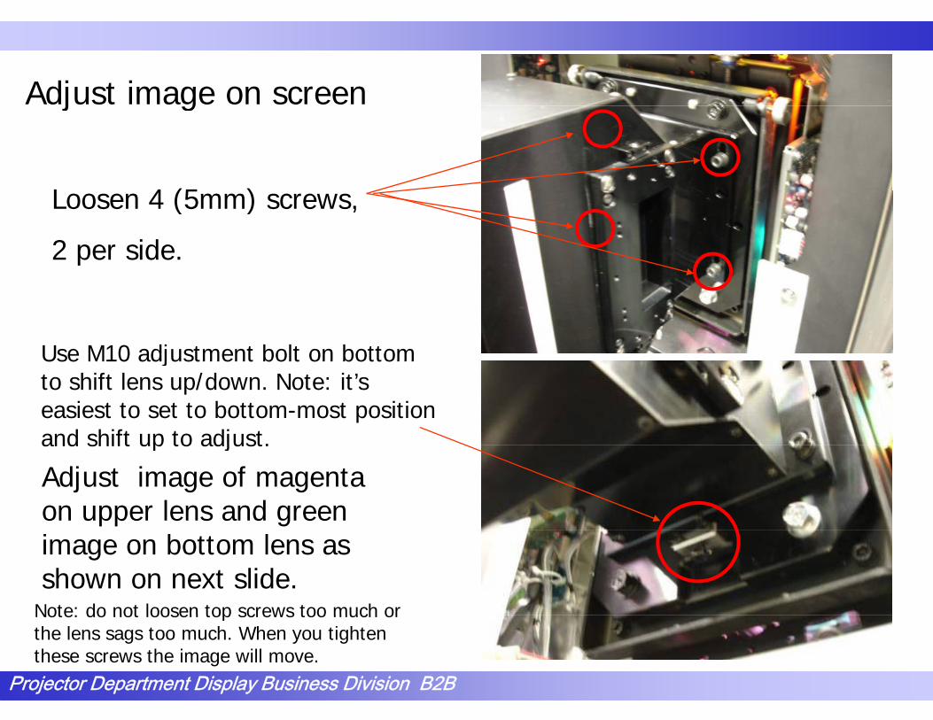
Adjust image on screen
L 4 (5 )
j g
Loosen 4 (5mm) screws,
2 per side.
Use M10 adjustment bolt on bottomUse M10 adjustment bolt on bottom to shift lens up/down. Note: it’s easiest to set to bottom-most position and shift up to adjust.
Adjust image of magenta on upper lens and green
and shift up to adjust.
image on bottom lens as shown on next slide.
Note: do not loosen top screws too much or
Projector Department Display Business Division B2B
Note: do not loosen top screws too much or the lens sags too much. When you tighten these screws the image will move.

Adjust image on screen
NG: Green light is visible in t filttop filter.
OK O l M t i i iblOK: Only Magenta is visible in top filter; only green is visible in bottom filter.
Projector Department Display Business Division B2B

Adjust image on screen
Rough-adjust the zoom and the focus.
ZoomThumb
F
screw
FocusThumb Screw
Note: use front of lens to adjust focus.
Projector Department Display Business Division B2B

Adjust the image on screen
Loosen 4 screws. (3mm)N t D ’t lNote: Don’t loosen screws too much. If lens sags the image will move when retightening them.
Adjust the V shift ofAdjust the V shift of the lens by using these screws. (3mm) The adjustment for the bottom lens is below the bottombelow the bottom lens.
Projector Department Display Business Division B2B

7. Set up 3D lensChoose “Prism Adjust” in test pattern’s box
A h i th t lid A h i t l liAs shown in the next slide. Arrange green horizontal line above and below the image evenly.
Projector Department Display Business Division B2B

7. Set up 3D lens
Adjust the rotation of h i
Loosen these 2 screws.
the prism
• Both right and left image lean to the right, if this is adjusted.
• Both right and left image left lean to the left, if this is adjusted.
Projector Department Display Business Division B2B

Adjust rotation of the prismAdjust rotation of the prism
When the prism is adjusted correctly, you will see a clean
lid magenta li t thsolid magenta line at the top and a clean solid green line at the bottom as shown.as shown.
Note: Both of these lines should be a constant thicknessshould be a constant thickness left to right. If not, you will need to adjust the prism.
Projector Department Display Business Division B2B

Adjust rotation of the prism
Loosen Upper screw a half turn,Th ti ht L
Adjust rotation of the prism
Then tight Lower screw.
Loosen Lower screw a half turnLoosen Lower screw a half turn,Then tight Upper screw.
Projector Department Display Business Division B2B

Adjust rotation of the prism
This is the correct way the lines h ld l kshould look.
This is incorrect. Notice both greenand magenta at the top.
This is incorrect. Notice the thinner to
Projector Department Display Business Division B2B
thicker green line at the bottom.

Adjustment for convergence
Choose “Frame Adjust” in Test Pattern box.Choose Frame Adjust in Test Pattern box.
First adjust Zoom, Focus, V Shift of the left eye on the screen (Bottom lens)(Bottom lens).
Next, adjust Zoom Focus V Shift, of the right eye on the screen (Top lens)(Top lens).
Projector Department Display Business Division B2B

Electric Adjustment for convergence
Choose “Frame Adjust” in Test Pattern’s box.
Click “Position Adjust”.
Center on the screen with H Adjust of L/R Synchronize.j / yV adjust must be left zero.
Close “Position Adjust” and choose “Convergence adjust” in Test j g jPattern’s box.
Click “Position Adjust”.
Match the L/R image with H Adjust and V adjust of right-eye image.
Projector Department Display Business Division B2B

Electric Adjustment for convergence
Adjust with H size, H Tilt, V Tilt and V Bow if needed.
H Tilt +
V Tilt +
V Bow +
Each situation, movable rangeis about 2 pixels. Use this functionV Bow +after precise adjustment of mechanicaladjustment.
Projector Department Display Business Division B2B

Masking adjustment
Choose “Frame Adjust” in Test Pattern’s box.
Click “Position Adjust”.j
Adjust “Masking Adjust” in L/R Synchronize.Can adjust L/R images togetherCan adjust L/R images together.Double click on the grey boxes to bring up the pop up window to adjust H/V
Use Masking Adjust of right side if there is a difference in masking for L and R. g
Projector Department Display Business Division B2B

Masking adjustmentg j
Adjust masking for both of L/R on L/R Synchronize and fine adjust on Rightadjust on Right.
Projector Department Display Business Division B2B

Point of Masking adjustment
If in Scope Full Height, it will look like this center point is padjusted.
This case, the adjustment canThis case, the adjustment can look like this if adjusting the masking of V for right and left corners.
Projector Department Display Business Division B2B

CSC adjustment
After adjustment for L/R, make sure to return to “Function for 3D” tab and re-adjust CSC of L/R.
Select colorspace for L/R images.
Projector Department Display Business Division B2B

CSC adjustment
Turn on the muting to mute t t f i ht i loutput for right eye signal.
O th “M i t ” t bOpen the “Maintenance” tab on SRXC. Then, click Color Space Converter.p
Projector Department Display Business Division B2B

CSC Adjustment-Select “Single 3D Left 1” in “Color” for “Left Image”.
- Select “Single 3D Right 1” in “Color” for “Right Image”Select Single 3D Right 1 in Color for Right Image .
Projector Department Display Business Division B2B

CSC Adjustment, cont●CSC adjust; shoot Green-1, Blue-1 and Gray 10 only.-Select the “Maintenance” tab then select “Color Space Converter”.-Choose “Signal 3D Left 1” as Color Space, select “Reset” then “Apply”.-Place the left lens of a set of 3D glasses over the lens of the CS100A.ace t e e t e s o a set o 3 g asses o e t e e s o t e CS 00Make sure the 3D glasses & CS100A are level with the floor.t t e oo-Enter the x,y readingsinto the “Input Color Measurement”Co o easu e e tregion for Red1, Green1, Blue1and Gray 10.-Record the 1st readings for eco d t e ead gs oR-1, G-1, B-1 & G-10.-Select “CALC”-Shoot the Gray 10S oot t e G ay 0pattern again and confirm the readings are within .006 of
Projector Department Display Business Division B2B
t 006 othe target values.-Select “Apply”.

CSC AdjustmentChoose “Signal 3D Right 1” as Color Space select “Reset” and “Apply”-Choose Signal 3D Right 1 as Color Space, select Reset and Apply .
-Place the right lens of a set of 3D glasses over the lens of the CS100A.Make sure the 3D glasses & CS100A areglasses & CS100A are level with the floor.-Enter the x,y readingsinto the “Inputinto the Input Color Measurement”region for Red1, Green1, Blue1and Gray 10and Gray 10.-Select “CALC”-Shoot the Gray 10pattern again andpattern again and confirm the readings are within .006 ofthe target valuesthe target values.-Select “Apply”.
Projector Department Display Business Division B2B

Function memory savey
Save to Function Memory after complete setting.Memory will be displayed as “3D” in 3D mode.
Projector Department Display Business Division B2B

Function memory save
In a theater where sidemasking is set for “Flat” size, choose “Flat Full Height”choose Flat Full Height .
In a theater where the masking is vertical (top-bottom)and the masking is set for “Scope” choose “Scopebottom)and the masking is set for Scope , choose Scope Limited Height”.
In this case, adjust vertical centering control with “Position gAdjust”, “L/R Synchronize” and V adjust.
Adjust masking in this mode.
After adjustment, save it on Function memory.
Projector Department Display Business Division B2B

3D Gamma Table Switching
Do not use this function.
Don’t change the pre-setting value.
Can switch if it has memory for Table 2(after R220/1), but
di l l icannot display normal image without adjustment of Table 2.
Cannot switch without memory for Table 2.
Projector Department Display Business Division B2B

L/R Contrast adjustmentj
Perform CSC BEFORE Contrast balancePerform CSC BEFORE. Contrast balance
Choose “Contrast Adjust” in test pattern box.
Measure brightness of both L/R images (squares) shooting through the polarization glasses. Use the darker image as
freference.
Adjust contrast setting in SRXC to match image’s.
Projector Department Display Business Division B2B

8. Ghost buster adjustment
Projector Department Display Business Division B2B

8 Ghost buster adjustment8. Ghost buster adjustment
Select Ghost buster in maintenance tab
Projector Department Display Business Division B2B

8 Ghost buster adjustmentSelect Red test pattern
8. Ghost buster adjustment
Using your right eye only with the 3D Glasses, adjust so that you cannot see the “blocks” (Blend them into the background)
Continue with green and blue with the same proceduresame procedure.
Note: Due to the reflectivity of theNote: Due to the reflectivity of the screen. It is best to sit directly in front of the vertical row of blocks you are adjusting. I.E. center row. Vi t f L ft id iView center of screen. Left side view in front of the left side..etc.
Projector Department Display Business Division B2B
Color selection

8. Ghost buster adjustment8. Ghost buster adjustment
Overall adjustment ( View center)
Left side adjust ( View left side)
I think you see a pattern here for continuinghere for continuing.
Projector Department Display Business Division B2B

Test patternNote: Remember this is looking through your
If you see this, there is ghosting
Note: Remember this is looking through your right eye only!!! (Close your left eye)
y , g g
Right eye signal( dark red )
Adjust to this.
Left eye signal
Projector Department Display Business Division B2B
( 9 red squares on black )

9. 3D/2D SET UP FROM PJT
Projector Department Display Business Division B2B

9. 3D/2D SET UP FROM PJT9. 3D/2D SET UP FROM PJT
Select Menu
Projector Department Display Business Division B2B

9. 3D/2D SET UP FROM PJT9. 3D/2D SET UP FROM PJT
Select Projector
Projector Department Display Business Division B2B

9. 3D/2D SET UP FROM PJT9. 3D/2D SET UP FROM PJT
l jSelect Projector type
Projector Department Display Business Division B2B

9. 3D/2D SET UP FROM PJT9. 3D/2D SET UP FROM PJT
Depending on the “D” you are changing to please select. Th l t “ l ”Then select “close”
Projector Department Display Business Division B2B

9. 3D/2D SET UP FROM PJT9. 3D/2D SET UP FROM PJT
Then select projector.
Then function setup.
Projector Department Display Business Division B2B

9. 3D/2D SET UP FROM PJT9. 3D/2D SET UP FROM PJT
Again, depending on what “D” selection you made“D” selection you made. Select the proper function setting. (scope, flat, 3D scope 3D flat etc.)
Projector Department Display Business Division B2B

9. 3D/2D SET UP FROM PJT9. 3D/2D SET UP FROM PJT
Select Projector.
Then Adjustment.
Projector Department Display Business Division B2B

9. 3D/2D SET UP FROM PJT9. 3D/2D SET UP FROM PJT
Note: these set-up patterns are for 3D. If f 2D it ld t t itfor 2D it would state it here.
For selecting set-up patterns
Projector Department Display Business Division B2B

9. 3D/2D SET UP FROM PJT9. 3D/2D SET UP FROM PJT
Test Pattern selection for 3D
Projector Department Display Business Division B2B

9. 3D/2D SET UP FROM PJT9. 3D/2D SET UP FROM PJT
Registration Adjust
Projector Department Display Business Division B2B

9. 3D/2D SET UP FROM PJT9. 3D/2D SET UP FROM PJT
H / V Image position on theH / V Image position on the SXRD chip.
Note: L/ R adjust simultaneously.
Then Right eye only.
Left eye is the referenceLeft eye is the reference.
Projector Department Display Business Division B2B

9. 3D/2D SET UP FROM PJT9. 3D/2D SET UP FROM PJT
You are able to mute the Left eye or right eye y g yindividually. Or both at the same time.
Projector Department Display Business Division B2B

9. 3D/2D SET UP FROM PJT9. 3D/2D SET UP FROM PJT
Projector Department Display Business Division B2B

9. 3D/2D SET UP FROM PJT9. 3D/2D SET UP FROM PJT
Projector Department Display Business Division B2B

9. 3D/2D SET UP FROM PJT9. 3D/2D SET UP FROM PJT
Projector Department Display Business Division B2B

Adjust rotation of the prism
OK: green line appears only at t N t G li h ttop. Note: Green line has to show on lower side as well when mechanical V shift on the lens is ec a ca s t o t e e s sadjusted.
OK: The green line is divided one above the other equally andone above the other equally and not lack to the edge of the screen.
Projector Department Display Business Division B2B

10 Filter Alignment10. Filter Alignment
Projector Department Display Business Division B2B

Align filter assemblyThe 3D Lens assembly ships with filter assemblies attached in the retracted position as shown.
The filters are not aligned at the factory. They must be alignedfactory. They must be aligned after the 3D lens alignment to match theater conditions.
If filters are ever removed fromIf filters are ever removed from the projector, please note that there both filters are not identical. The proper orientation i h th filt ith this shown, the filter with the “RealD” logo should always be on top.
Projector Department Display Business Division B2B

Wh li i 3D l bl filt d t bWhen aligning 3D lens assembly, filters need to be centered on beam.
Loosen plastic knobs enough to rotate filtersinto beam, keeping filters at rear-mostposition, then retighten.
Projector Department Display Business Division B2B

O 3D l li d filt li t b iOnce 3D lenses are aligned, filter alignment begins.
Project contrast test pattern on screen. It will look like thiswill look like this.
A faint secondary image generated by internal reflections in the filter will appear as shown when the filter is near a right angle to the beamthe beam.
Projector Department Display Business Division B2B

R fl t d iRemove reflected image.
Place lens cover on bottom beam. Rotate Place lens cover on bottom beam. Rotate top filter holder up/down to move the reflected image until it is off the screen at the top.
Maintain the angle which extinguishes theMaintain the angle which extinguishes the reflected image and move the filter assembly forward until the beam fills the filter without clipping. Observe beam both
i id d t id f filt t bon inside and outside of filter to be sure beam is not clipped on any edge. Note: For wide beams the filter assembly will not need to move out much; for narrow beams
Projector Department Display Business Division B2B
the filter may need to move to its forward limit.

Set bottom filter.
Set bottom filter to match angle and position of top filter. Assure that the beam is not clipped by the hardware surrounding the filters and the ghost image is eliminated.
Tighten plastic knobs securely.
Projector Department Display Business Division B2B
Tighten plastic knobs securely.

Mark settings.
If the 3D lens assembly should be removed and placed into its storage box, the filter assembly will need to be retracted so that the assembly will fit into the box. This deletes the filter alignment. To make it easy to recapture these settings for the same theater, mark the g ,side brackets with any marker that can be seen as shown.
Although this will revive the previousAlthough this will revive the previous alignment, it is important to verify that the beam is not clipped after re-installation.
Projector Department Display Business Division B2B

11. Storage of 3D Lens and Filters
Figure 12 Lens Assembly Packing CaseFigure 12. Lens Assembly Packing CaseThe 3D Lens Assembly is shipped in its packing case with the filters fully retracted.The assembly should always be safely stowed back in its case when not mounted on the projector.Depending on the positions of the filters however, you may need to retract them before stowing the assembly.Note that It is possible to extend the storage area of the case by pulling out the removable foam strips.
Projector Department Display Business Division B2B
p g y p g pThe storage case may be used to store your 2D lens as well while showing 3D presentations.


![Capture One Pro 10 The Professional Choice In Imaging Software · • Sony 28–75mm F2.8 SAM Lens profile • Sony 135mm F2.8 [T4.5] STF Lens profile • Sony Ultra Wide Converter](https://img.dokumen.tips/doc/110x75/5f5523fbc734c863dc0098b7/capture-one-pro-10-the-professional-choice-in-imaging-software-a-sony-28a75mm.jpg)