Embed Size (px)
Citation preview

SonoCalc® IMT 5.0
User Guide c

SonoSite, Inc.21919 30th Drive SEBothell, WA 98021USAT: 1-888-482-9449 or 1-425-951-1200F: 1-425-951-1201
SonoSite LtdAlexander House40A Wilbury WayHitchinHerts SG4 0APUKT: +44-1462-444800F: +44-1462-444801
180PLUS, M-Turbo, MicroMaxx, NanoMaxx, S Series, SiteLink, SonoCalc, SonoSite, the SonoSite logo, SonoSite TITAN, and TITAN are registered (in some jurisdictions) and unregistered trademarks owned by SonoSite, Inc.
Non-SonoSite product names may be trademarks or registered trademarks of their respective owners.
The SonoSite ultrasound systems referenced in this document may be covered by one or more of the following U.S. patents: 5722412, 5817024, 5893363, 6135961, 6203498, 6364839, 6371918, 6383139, 6416475, 6447451, 6471651, 6569101, 6648826, 6575908, 6604630, 6817982, 6835177, 6962566, 7169108, 7449640, 7534211, 7549961, 7588541, 7591786, 7604596, 7643040, 7686766, 7694814, 7727153, 7740586, 7804970, 7809400, 7819807, 7841575, 7849250, 7867168, 7883276, D456509, D461895, D509900, D538432, D544962, D558351, D559390, D591423, D592750, D592760, D625014, D625015, and by the following counterpart foreign patents: AU727381, AU730822, CA2372152, CA2372158, CA2373065, CN ZL 97113678.5, CN ZL 98106133.8, CN ZL 98108973.9, CN ZL 200830007734.8, DE60021552.0, DE60029777.2, DE60034670.6, DE69730563.5, DE6980539.6, DE69831698.3, DE60 2004 23 816.3-08, FR0815793, FR0875203, FR0881492, FR1175713, FR1180970, FR1589878, GB0875203, GB0881492, GB1175713, GB1180970, GB1180971, GB1589878, IT0815793, IT0881492, IT1175713, IT1589878, KR528102, KR532359, NO326202, NO326814, NZ542968, RCD000897368-0001, SP0815793, SP0881492, SP1589878. Patents pending.
P08450-03 05/2011Copyright 2011 by SonoSite, Inc.All rights reserved.
Caution: Federal (United States) law restricts this device to sale by or on the order of a physician.

Table of Contents
Introduction .................................................................................................................... 1Compatible Transducers ............................................................................................. 1Safety ................................................................................................................................. 2About the Work Area .................................................................................................... 3
Screen Layout ........................................................................................................ 3Exam Data Pane .................................................................................................... 4Menus ....................................................................................................................... 8
Patient Images ................................................................................................................ 9Setting the Exam Folder .................................................................................... 9Starting a New Exam .........................................................................................10Opening Saved Exams ......................................................................................10
Patient Information .....................................................................................................11Image Calibration ........................................................................................................12
Automatic Calibration ......................................................................................12Manual Calibration ............................................................................................12Image Calibration Verification .......................................................................14
Navigation Commands ..............................................................................................15Navigating Current Image ...............................................................................15Navigating Active View ....................................................................................15Adjusting IMT Measurements ........................................................................16Navigating between Image Files ..................................................................18
Measurements Overview ..........................................................................................19IMT Measurements .....................................................................................................20
Auto Mode ............................................................................................................20Sketch Mode ........................................................................................................22Trace Mode ...........................................................................................................26Setting a Reference Point ................................................................................28Changing Default IMT Measurement Settings ........................................29
Plaque Measurements ...............................................................................................29Measurement Results ................................................................................................30
Selecting Saved Measurements ....................................................................30Regenerating Measurements ........................................................................30Deleting Saved Measurements .....................................................................31Excluding Imported Measurements ............................................................31Editing Measurements .....................................................................................31Reviewing Saved Exams ..................................................................................32
Manual Calipers ............................................................................................................32IMT Report ......................................................................................................................33
Customizing Report Stationery .....................................................................33Viewing IMT Report ...........................................................................................34Saving Report as PDF ........................................................................................34Printing Report ....................................................................................................34
Graph Setup ..................................................................................................................35Custom IMT Graph Tables ...............................................................................35
i

Exporting Data ............................................................................................................. 36Results Summary ......................................................................................................... 37References ...................................................................................................................... 37Distance Measurement Accuracy .......................................................................... 39Technical Support ....................................................................................................... 39
ii

IntroductionSonoCalc® IMT measures the intima media thickness (IMT) of the carotid artery and plaque using digital ultrasound images. Images from M-Turbo®, S Series™, MicroMaxx®, TITAN®, and SonoSite® 180PLUS™ ultrasound systems are typically transferred to a personal computer (PC) using SiteLink™ Image Manager (SiteLink). For NanoMaxx®, M-Turbo, and S Series ultrasound systems, images can be imported from a USB storage device.
You can measure the IMT of the near or far walls of the carotid artery. Images must be obtained using a transducer that is compatible with SonoCalc IMT. SonoCalc IMT generates a report with the patient’s IMT value. This information can be used with other medical information to assess the cardiovascular health of a patient.
See the ultrasound system user guide and SiteLink Image Manager User Guide for additional information on operating the ultrasound system and transferring images.
Compatible TransducersSonoCalc IMT is compatible with the following transducers:
Table 1: System and Transducer Compatibility
Transducer NanoMaxx S SeriesM-Turbo MicroMaxx TITAN 180PLUS
HFL38x/13-6 MHz – – – –
HFL38/13-6 MHz – – – –
L38n/10-5 MHz – – – –
L38xi/10-5 MHz – – – –
L38x/10-5 MHz – – – –
L38e/10-5 MHz – – – –
L38/10-5 MHz – – –
L25n/13-6 MHz – – – –
L25x/13-6 MHz – – – –
L25e/13-6 MHz* – – – –
L25/10-5 MHz – – – *
* Images from these transducers are not automatically calibrated on MicroMaxx 3.3 (or earlier) ultrasound systems. The images from 180PLUS or MicroMaxx 3.3 (or earlier) ultrasound systems can be manually calibrated. See “Manual Calibration” on page 12.
1

SafetyPatient Safety
WARNING: To ensure high-quality images, all patient images must be obtained by qualified and trained individuals. See the ultrasound system user guide for information on using the system.
WARNING: To avoid misdiagnosis, be aware that the SonoCalc IMT user interface is in English only and follows English-language conventions, although you can import exams from an ultrasound system localized in French, German, Italian, Spanish, or Brazilian Portuguese. The IMT report included with an IMT exam from a non-English ultrasound system may have details formatted differently from those in SonoCalc IMT.
WARNING: To avoid measurement errors, all images must be obtained using the NanoMaxx, S Series, M-Turbo, MicroMaxx, TITAN, or 180PLUS ultrasound system with a transducer that supports SonoCalc IMT. Images must be transferred in high-resolution bitmap (24 bit) format.
WARNING: To avoid patient injury, IMT results should not be used as a sole diagnostic tool. All IMT results should be interpreted in conjunction with other clinical information or risk factors.
WARNING: To avoid interpretation errors that might affect patient safety, only a qualified and trained individual should interpret IMT results.
WARNING: To avoid interpretation errors that might affect patient safety, IMT measurements that are saved and intended to populate the default graphs should be made only from images of the distal 10 mm of the common carotid artery (CCA). This tool is not intended for measuring the bulb or the internal carotid artery (ICA).
WARNING: To avoid patient injury associated with misdiagnosis or measurement errors, verify that the patient information is accurate before transferring images from the ultrasound system and before performing any IMT measurements.
WARNING: To avoid patient injury or measurement errors, verify patient information before every exam.
WARNING: To ensure accurate age computations, make sure that the date on your computer is correct.
WARNING: To avoid misdiagnosis, do not use images from an ultrasound system that has the MBe (SonoMBe™ multi-beam imaging, enhanced) control on. If the ultrasound system supports MBe, turn off MBe before saving images for use in SonoCalc IMT.
2

About the Work AreaThe SonoCalc IMT work area has menus and three panes: two that display the image and one that displays exam data. The Exam Data pane has patient data, measurement results, and more.
Screen Layout
Figure 1 SonoCalc IMT Screen
Electrical Safety
WARNING: To avoid the risk of electrical shock, connect only cables recommended by SonoSite to peripherals. Contact SonoSite or your local representative for the accessory cable(s) available from or recommended by SonoSite.
WARNING: To avoid the risk of electrical shock, the electrical connection of a personal computer to the ultrasound system must be in a manner that complies with Table BBB.201 of IEC 60601-1-1:2001.
1 Exam Data Pane
Displays current and/or saved information and instructional prompts. See “Exam Data Pane” on page 4.
2 Active View Pane
Displays the image for performing measurements and zooming in or out. A status bar below the image displays the screen size in millimeters, x and y coordinates, pixel intensity, and Reference Line data.
31
2
3

Exam Data PaneThe Exam Data pane contains four tabs: Summary, Individual, Imported, and Report Configuration. Each tab displays current and/or saved information for the selected exam as well as instructional system prompts.
Summary TabWhen SonoCalc IMT first opens, it defaults to the Summary tab. The Summary tab contains Patient Information and Summary Results.
Figure 2 Exam Data Pane: Summary Tab
Patient Information
The Patient Information area displays current patient information including Name, Patient ID, Date of Birth, Age at Exam, Gender, Ethnic Origin, Exam Date, and Referring Dr. Some patient information is editable. See “Patient Information” on page 11.
Summary Results
The Summary Results area displays exam summary measurements for Mean IMT, Max Region IMT, and Plaque. You can print this information or save it as PDF (See “Printing Report” on page 34 and “Saving Report as PDF” on page 34). If the summary results include imported measurements, an asterisk appears next to the measurement and “*Includes Imported” appears below the results.
3 Current Image Pane
Displays the entire image and serves as a navigational aid. The green rectangle, the region of interest box (ROI), indicates the portion of the image that currently appears in the Active View pane.
4

Individual TabThe Individual tab contains Saved Results and Current Results. The Exam Data pane automatically opens to the Individual tab whenever a measurement is performed or edited.
Saved Results
The Saved Results area displays IMT and Plaque measurement tables. If more measurements are taken than show in the table, you can scroll to view them. You can regenerate or delete measurements as well as edit comments.• The IMT measurement table displays all saved IMT measurements for the right side and
from previous versions of SonoCalc IMT (which did not specify sides). The most recent is first. Each measurement includes the measurement Number, Label, Mean, Max, Width, and Comment data.
• The Left IMT measurement table displays all saved IMT measurements for the left side. The most recent is first. Each measurement includes the measurement Number, Label, Mean, Max, Width, and Comment data.
• The Plaque measurement table displays all saved plaque measurements with the most recent first. Each measurement includes the measurement Number, Label, Distance, and Comment data.
Current Results
The Current Results area displays either IMT or plaque results depending on the active measurement being made. The pixel size for the image currently shown appears beneath the table. For smoothing, select the Smoothing check box. The measurement in the Current Results table can be saved, which automatically adds it to the appropriate Saved Results table.
Imported TabThe Imported tab contains imported results for IMT, Diameter Reduction, Area Reduction, and Plaque measurements saved on M-Turbo and MicroMaxx ultrasound systems. On the NanoMaxx ultrasound system, the Imported tab contains imported results for IMT and Plaque measurements.
These tables display all saved measurements in the order defined by ultrasound system setup. All measurements displayed in the tables are included in the exam report unless selected and excluded.
• The IMT table displays all saved imported IMT measurements showing Label, Mean, Max, and Width data. If more measurements are taken than show in the table, you can scroll to view them.
• The Diameter Reduction table displays diameter reduction measurements showing Label, Dist 1, Dist 2, and% Diameter Reduction data.
• The Area Reduction table displays area reduction measurements showing Label, Area 1, Area 2, and% Area Reduction data.
WARNING: Before starting an exam, verify that imported measurements are accurate and complete.
5

• The Plaque table displays all saved plaque measurements showing Label and Distance data.
Exclude from Exam lets you select which imported results you want to include in report averages. See “Excluding Imported Measurements” on page 31.
Report Configuration TabThe Report Configuration tab lets you specify how data are plotted in the graphs that appear in the report. You can also exclude graphs from the report.
Specify how data plot in graphsDo the following under First Plot and Second Plot:a Select Show.
b Under Value to Plot, select a measurement type. (See also “Value to Plot list” on page 7.)
c Specify the population to plot against:
• To use data from the default IMT graph tables, select Default. The Plot values against population data from field is filled automatically.
• To use data from a custom IMT graph table that you have set up, deselect Default, and then select the custom IMT graph table from the Plot values against population data from list. (Only graph tables for a population of the same gender as the patient are available.)
For more information on the IMT graph tables and customizing them, see “Graph Setup” on page 35.
Exclude graphs from reportDeselect Show under the plot or plots you want to exclude:• First Plot• Second Plot
WARNING: Prior to use, verify that custom table data entries are correct. SonoSite recommends previewing the report before using for an exam.
6
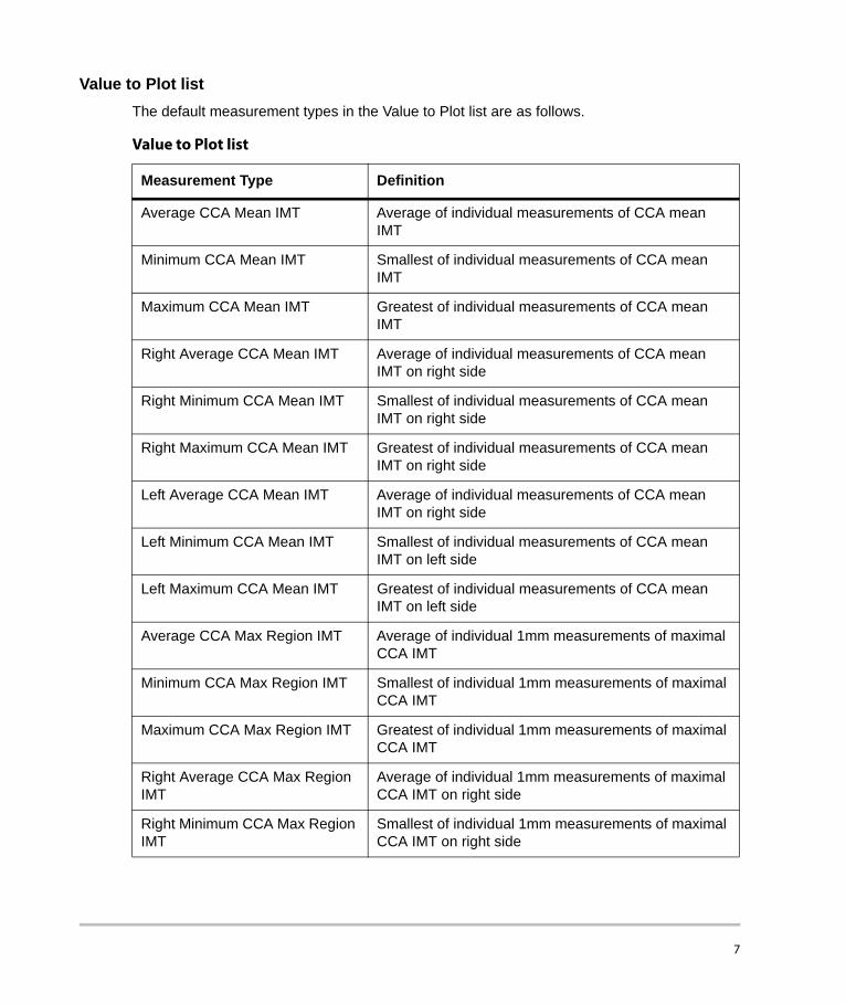
Value to Plot listThe default measurement types in the Value to Plot list are as follows.
Value to Plot list
Measurement Type Definition
Average CCA Mean IMT Average of individual measurements of CCA mean IMT
Minimum CCA Mean IMT Smallest of individual measurements of CCA mean IMT
Maximum CCA Mean IMT Greatest of individual measurements of CCA mean IMT
Right Average CCA Mean IMT Average of individual measurements of CCA mean IMT on right side
Right Minimum CCA Mean IMT Smallest of individual measurements of CCA mean IMT on right side
Right Maximum CCA Mean IMT Greatest of individual measurements of CCA mean IMT on right side
Left Average CCA Mean IMT Average of individual measurements of CCA mean IMT on right side
Left Minimum CCA Mean IMT Smallest of individual measurements of CCA mean IMT on left side
Left Maximum CCA Mean IMT Greatest of individual measurements of CCA mean IMT on left side
Average CCA Max Region IMT Average of individual 1mm measurements of maximal CCA IMT
Minimum CCA Max Region IMT Smallest of individual 1mm measurements of maximal CCA IMT
Maximum CCA Max Region IMT Greatest of individual 1mm measurements of maximal CCA IMT
Right Average CCA Max Region IMT
Average of individual 1mm measurements of maximal CCA IMT on right side
Right Minimum CCA Max Region IMT
Smallest of individual 1mm measurements of maximal CCA IMT on right side
7
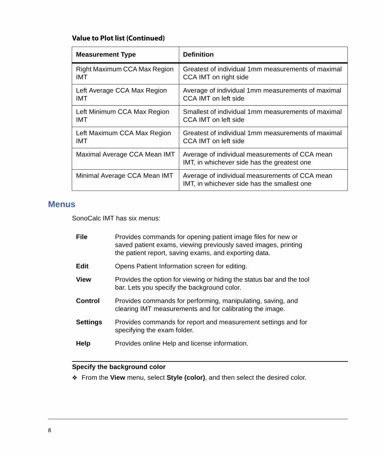
MenusSonoCalc IMT has six menus:
Specify the background colorFrom the View menu, select Style (color), and then select the desired color.
Right Maximum CCA Max Region IMT
Greatest of individual 1mm measurements of maximal CCA IMT on right side
Left Average CCA Max Region IMT
Average of individual 1mm measurements of maximal CCA IMT on left side
Left Minimum CCA Max Region IMT
Smallest of individual 1mm measurements of maximal CCA IMT on left side
Left Maximum CCA Max Region IMT
Greatest of individual 1mm measurements of maximal CCA IMT on left side
Maximal Average CCA Mean IMT Average of individual measurements of CCA mean IMT, in whichever side has the greatest one
Minimal Average CCA Mean IMT Average of individual measurements of CCA mean IMT, in whichever side has the smallest one
Value to Plot list (Continued)
Measurement Type Definition
File Provides commands for opening patient image files for new or saved patient exams, viewing previously saved images, printing the patient report, saving exams, and exporting data.
Edit Opens Patient Information screen for editing.
View Provides the option for viewing or hiding the status bar and the tool bar. Lets you specify the background color.
Control Provides commands for performing, manipulating, saving, and clearing IMT measurements and for calibrating the image.
Settings Provides commands for report and measurement settings and for specifying the exam folder.
Help Provides online Help and license information.
8

Patient ImagesPatient images are organized into exam files for patients. These files contain data as well as image information. For SonoCalc IMT to operate properly, you must keep data and report files associated with image files together.
Moving files is not recommended. If you must move files, be certain to move the entire Study folder for that patient.
Do not remove, modify, or duplicate any files in the folder.
Patient images can be transferred to SonoCalc IMT as follows:• Transfer from SiteLink: M-Turbo, S Series, MicroMaxx, TITAN, and 180Plus• Import from USB storage device: M-Turbo, S Series, and NanoMaxx
Ensure that all images are transferred in high-resolution bitmap (2 4 bit) format. Access these files for existing or new patients when starting a new exam or opening a saved exam.
Setting the Exam FolderBy default, exams save to the C:\SonoCalc\ExamData\ folder. You can change this folder.
You can view and edit exams from an earlier version of SonoCalc by setting the exam folder to the location of the earlier version (C:\Program Files\SonoSite\SonoCalc\ by default). In Microsoft Vista, these exams need to be moved before they can be modified.
If you want to keep groups of exams separate, you can use different storage locations.
Set the Exam Folder1 From the Settings menu, select Exam Folder.2 Browse to a folder.
If you want to make a new folder, browse to the location, and click Make New Folder. A new folder with an editable folder name appears. Type a name (or right-click the folder name and select Rename).
3 Click OK.
WARNING: To avoid loss of patient information, use extreme care when moving patient images once they are transferred to your PC. Improperly moving image files may cause errors in SonoCalc IMT operations.
9

Starting a New ExamUp to nine exams can be created for a particular patient on a given day.
Start New Exam1 From the File menu, select New Exam.
The Open dialog box appears.2 Open a patient image.
The Select a Patient dialog box appears. 3 Select New Patient or an existing patient.
If you select New Patient, the Patient Information screen appears. Fill in the appropriate fields. See “Patient Information” on page 11.The first time SonoCalc IMT starts, the only option is New Patient.
4 Click OK.
Opening Saved ExamsExams that have been saved can be opened at any time. Saved exams are assigned a date at the time they are completed in SonoCalc IMT. This date may be different from the date the images were taken.
Open Saved Exam1 From the File menu, select Open Saved Exam.
The Open Saved Exam dialog box appears.Groups of saved measurements are listed and identified as Measures.kpt or Measures.xml.If a previous file has been reviewed and other measurements are performed, each modified exam is stored in a new file with a new file name, for example, Measures.xml or Measures.kpt.Note: If you open an exam saved in a previous version, SonoCalc IMT prompts you to update user-defined tables.
2 Select the desired file.The patient information and all saved measurements for this patient exam open.
3 Click OK.The patient image opens.The first measurement, 1 in the # list, is automatically regenerated and displayed on the active image, if available.If any of these saved measurements are deleted or new measurements are added, a new file is generated for this exam. The original file remains intact.
10

To regenerate other saved measurements for this file, see “Regenerating Measurements” on page 30.Note: Enhancements to the system software may cause small insignificant measurement differences in exams from an earlier version of SonoCalc IMT that are regenerated.
Patient Information
To enter patient information into the Patient Information screen, start a new exam. (See “Starting a New Exam” on page 10.)
Some patient information may be automatically entered.
Complete all applicable fields. Fields with an asterisk are required.• Last Name: Patient’s last name.• First Name: Patient’s first name. Optionally, add a space and the middle name or initial. • ID: Patient’s ID. (Optional)• Date of Birth: Year, month, and day of birth. This date must reflect an age at exam of five
to 100 years.• Age at Exam: Patient’s age on the date of exam.• Gender: Male or Female.• Ethnic Origin: Patient’s ethnic origin.• Date of Exam: Year, month, and day of the exam, if not automatically entered.• Referring Dr: Physician’s full name. (Optional)• Comments: Additional information about the patient. Press CTRL+ENTER to start a new line
of text. (Optional)• Image Frame Selection: Non-ECG Gated (default) or ECG R Wave Gated.
Modify Patient Information:Do one of the following:• Select Patient Information from the Edit menu.• Click Edit on the Summary tab.
WARNING: To avoid patient injury associated with misdiagnosis or measurement errors, verify that the patient information is accurate before transferring images from the ultrasound system and before performing any IMT measurements.
11

Image CalibrationImages are automatically calibrated if they meet certain criteria. See “Automatic Calibration.”
The SonoCalc IMT measurement tools operate only on calibrated images. If the image is not automatically calibrated, you can perform a manual calibration. It is the user’s responsibility to perform an accurate manual calibration on any image that cannot be automatically calibrated.
Automatic CalibrationBefore starting an IMT measurement, always verify that the image calibration data matches the information on the current image. All patient images transferred from the NanoMaxx, S Series, M-Turbo, MicroMaxx, TITAN, and 180PLUS ultrasound systems are automatically calibrated if they meet the following criteria:• Image acquired using a transducer that is compatible with SonoCalc IMT. See “Compatible
Transducers” on page 1.• Image transferred and saved in high-resolution bitmap (24 bit) format. For instructions on
selecting file formats, see the SiteLink Image Manager User Guide, NanoMaxx Ultrasound System User Guide, S Series Ultrasound System User Guide, or M-Turbo Ultrasound System User Guide.
For information on verifying calibrations, see “Image Calibration Verification” on page 14.
Manual Calibration
Note: If SonoCalc IMT is unable to automatically calibrate an image, the following message appears: “Could not Auto-Calibrate.” SonoSite recommends using the depth markers on the right side of the image as landmarks for calibration.
Calibrate Image ManuallyNote: Before performing a manual image calibration, select two points between which you know the distance. You can use this distance to verify accurate calibration.1 Open the patient image.2 In the Current Image pane, click the first calibration landmark to center the ROI box over the
landmark.
WARNING: To avoid measurement errors, all patient images must be calibrated.
WARNING: To avoid measurement errors, always verify that the automatic calibration data matches the information on the current image. If the ultrasound image or annotation covers the depth markers, the automatic calibration may incorrectly calibrate the current image resulting in incorrect measurement results.
WARNING: If an image is manually calibrated, it is not recognized as a valid SonoSite image. Measurements performed on the image may be inaccurate. (SonoCalc IMT should be used only on images in which the pixel scale is 1:1.)
12

Use the depth markers as calibration landmarks.Zoom the image to ensure that the individual pixels on the depth markers are visible on the first calibration landmark. See “Navigating Active View” on page 15 for instructions to zoom.Re-centering the ROI box may be necessary after zooming.
3 Press the C key.4 In the Active View pane, click a pixel/location on the first calibration landmark to set as the
anchor pixel.The calibration landmark is a shape composed of many pixels.It does not matter which pixel/location in the calibration landmark is selected for the anchor pixel, but it is very important that the corresponding pixel/location on the second calibration landmark is selected for the second point.
5 In the Current Image pane, click the second calibration landmark to center the ROI box over the calibration landmark.
6 In the Active View pane, click the corresponding pixel/location that was selected for the anchor pixel/location to set the second point. A dialog box displays the following text: “How many millimeters between calibration points?”
7 Enter the distance, in millimeters, between the two calibration landmarks. For example, if there is 1 cm between the landmarks, enter 10 (10 mm = 1 cm).As a secondary check, see “Manual Calipers” on page 32 to measure the distance between the two previously determined points with a known distance. The distance between the points should be the same.
8 Press the ESC key to cancel the calibration process.
13

Image Calibration VerificationBefore starting an IMT measurement, always verify that the image calibration data match the information on the current image.
Figure 3 Calibration data on image and in Current Results area:
1 - Name of ultrasound system2 - Image depth
Verify Automatic Image Calibration 1 Verify that the name of the ultrasound system displayed in the Current Results area matches
the system used to acquire the image. See Figure 3.2 For 180PLUS and TITAN ultrasound systems, verify that the image depth in the Current
Results area matches the depth in the Current Image pane. The image depth is the distance from the skinline to the bottom of the ultrasound image.For zoomed images, “zoom” appears after the image depth in Current Results area.
WARNING: To avoid measurement errors, always verify that the automatic calibration data matches the information on the current image. If the ultrasound image or annotation covers the depth markers, the automatic calibration may incorrectly calibrate the current image resulting in incorrect measurement results.
2
1
14

If the name or depth do not match, perform a manual calibration. See “Calibrate Image Manually” on page 12.
Navigation CommandsNavigation commands control functions such as adjusting IMT measurements and navigating between image files.
Navigating Current ImageThe following procedures navigate the region of interest (ROI) box in the Current Image pane (upper left corner). The ROI box appears in the Active View pane.
Center ROI BoxClick where you want to center the ROI box.
Position ROI BoxDrag the ROI box to the desired location. The image area in the ROI box appears in the Active View pane.
Navigating Active ViewThe following commands navigate and control the Active View pane (lower image).
WARNING: On some international keyboards, you may not be able to manually adjust the purple Adventitia Constraint Line. SonoSite recommends manually adjusting other constraint lines or performing the measurement using Sketch mode.
WARNING: International keyboards may use different key combinations.
Keys Description
Any of the following:• F5• MINUS SIGN
• SHIFT+MINUS SIGN
• SHIFT+COMMA
Zooms out on the image.
15

Adjusting IMT MeasurementsThe following commands are available when the IMT measurement is active (IMT measurement boundary lines are visible):
Adjust Measurement Lines Laterally (Auto, Sketch, and Trace Modes)
Any of the following:• F6• PLUS SIGN
• =• SHIFT+PERIOD
Zooms in on the image.
Mouse wheel Rotating the mouse wheel moves the image up and down.
SPACEBAR-click Recenters the image.
Keys Description
Keys Description
LEFT ARROW Moves the IMT measurement region left 1 pixel.
CTRL+LEFT ARROW Moves the IMT measurement region left 10 pixels.
RIGHT ARROW Moves the IMT measurement region right 1 pixel.
CTRL+RIGHT ARROW Moves the IMT measurement region right 10 pixels.
UP ARROW Increases the width of the IMT measurement region by 2 pixels.
CTRL+UP ARROW Increases the width of the IMT measurement region by 20 pixels.
DOWN ARROW Decreases the width of the IMT measurement region by 2 pixels.
CTRL+DOWN ARROW Decreases the width of the IMT measurement region by 20 pixels.
16

Adjust Measurement Lines Vertically (Auto, Sketch, and Trace Modes)Adjust Lumen/Intima Boundary Lines
Adjust Media/Adventitia Boundary Lines
In Sketch or Trace mode, you can also move the measurement boundary lines by dragging.
Drag a Measurement Boundary Line (Sketch or Trace Mode)1 Move the mouse over a manually placed constraint line to highlight it.2 Drag the constraint line to a new vertical location which moves the linked IMT measurement
boundary line.
KeysAny of the following: Description
• F9• {
Moves the Lumen/Intima constraint line down, which moves the linked cyan Lumen/Intima IMT measurement boundary line.
• F10• }
Moves the Lumen/Intima constraint line up, which moves the linked cyan Lumen/Intima IMT measurement boundary line.
KeysAny of the following: Description
• F11• [
Moves the dark Media magenta constraint line down, which moves the linked cyan Media/Adventitia IMT measurement boundary line.
• F12• ]
Moves the dark Media magenta constraint line up, which moves the linked cyan Media/Adventitia IMT measurement boundary line.
• F7• CTRL+[
Moves the purple Adventitia constraint line down, which moves the linked cyan Media/Adventitia IMT measurement boundary line.
• F8• CTRL+]
Moves the purple Adventitia constraint line up, which moves the linked cyan Media/Adventitia IMT measurement boundary line.
17
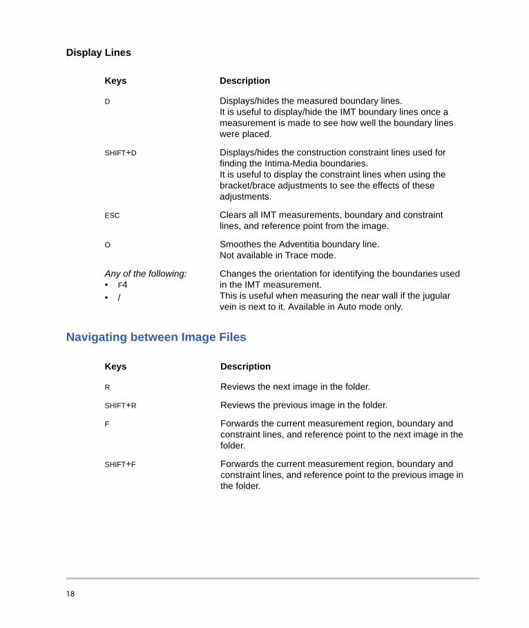
Display Lines
Navigating between Image Files
Keys Description
D Displays/hides the measured boundary lines.It is useful to display/hide the IMT boundary lines once a measurement is made to see how well the boundary lines were placed.
SHIFT+D Displays/hides the construction constraint lines used for finding the Intima-Media boundaries.It is useful to display the constraint lines when using the bracket/brace adjustments to see the effects of these adjustments.
ESC Clears all IMT measurements, boundary and constraint lines, and reference point from the image.
O Smoothes the Adventitia boundary line. Not available in Trace mode.
Any of the following:• F4• /
Changes the orientation for identifying the boundaries used in the IMT measurement.This is useful when measuring the near wall if the jugular vein is next to it. Available in Auto mode only.
Keys Description
R Reviews the next image in the folder.
SHIFT+R Reviews the previous image in the folder.
F Forwards the current measurement region, boundary and constraint lines, and reference point to the next image in the folder.
SHIFT+F Forwards the current measurement region, boundary and constraint lines, and reference point to the previous image in the folder.
18

Measurements Overview
There are three modes for performing IMT measurements:• Auto mode• Sketch mode• Trace mode
There is one tool for performing plaque measurements: Plaque Measurements.
When you perform a measurement, SonoCalc IMT displays the following information in the Current Results area. IMT or Plaque measurement results are displayed based upon the active tool.• IMT (mm)
• Mean• Max Region• Width
• Plaque (mm)• Distance
When you save the measurement, SonoCalc IMT displays the following information in the Saved Results area:• IMT (mm), if right side is selected; or LEFT IMT (mm), if left side is selected
• Label• Mean• Max
WARNING: To ensure high quality images, all patient images must be obtained by qualified and trained individuals. See the ultrasound system user guide for information on using these systems.
WARNING: To avoid measurement errors, all images must be obtained using the NanoMaxx, S Series, M Turbo, MicroMaxx, TITAN, or 180PLUS ultrasound systems using a transducer that is compatible with SonoCalc IMT, and all patient images must be transferred in high-resolution bitmap (24 bit) format.
WARNING: To avoid patient injury, IMT results should not be used as a sole diagnostic tool. All IMT results should be interpreted in conjunction with other clinical information or risk factors.
WARNING: To avoid interpretation errors that might affect patient safety, IMT measurements that are saved and intended to populate the default graphs should be made only from images of the distal 10 mm of the common carotid artery (CCA). This tool is not intended for measuring the bulb or the internal carotid artery (ICA).
WARNING: To avoid patient injury associated with misdiagnosis or measurement errors, verify that the patient information is accurate before transferring images from the ultrasound system and before performing any IMT measurements.
19

• Width• Comment
• Plaque (mm)• Label• Distance• Comment
IMT MeasurementsYou can perform IMT measurements in Auto, Sketch, or Trace mode. Each mode uses colored measurement lines.
You can also set a reference point.
Auto ModeAuto mode provides automatic IMT measurements based on the user-defined location.
Auto Measurement LinesThe figure and table below show the lines available, their colors, and names as they appear for an auto measurement.
Figure 4 Auto Measurement Lines
Table 2: Auto Measurement Lines
Color Name
Yellow Lumen Constraint Line
Cyan Lumen/Intima Boundary Line
Magenta Dark Media Constraint Line
Cyan Media/Adventitia Boundary Line
Purple Adventitia Constraint Line
20
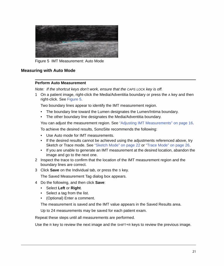
Figure 5 IMT Measurement: Auto Mode
Measuring with Auto Mode
Perform Auto MeasurementNote: If the shortcut keys don’t work, ensure that the CAPS LOCK key is off.1 On a patient image, right-click the Media/Adventitia boundary or press the A key and then
right-click. See Figure 5.Two boundary lines appear to identify the IMT measurement region. • The boundary line toward the Lumen designates the Lumen/Intima boundary.• The other boundary line designates the Media/Adventitia boundary.You can adjust the measurement region. See “Adjusting IMT Measurements” on page 16.To achieve the desired results, SonoSite recommends the following:• Use Auto mode for IMT measurements.• If the desired results cannot be achieved using the adjustments referenced above, try
Sketch or Trace mode. See “Sketch Mode” on page 22 or “Trace Mode” on page 26.• If you are unable to generate an IMT measurement at the desired location, abandon the
image and go to the next one.2 Inspect the trace to confirm that the location of the IMT measurement region and the
boundary lines are correct.3 Click Save on the Individual tab, or press the S key.
The Saved Measurement Tag dialog box appears.4 Do the following, and then click Save:
• Select Left or Right.• Select a tag from the list.• (Optional) Enter a comment. The measurement is saved and the IMT value appears in the Saved Results area. Up to 24 measurements may be saved for each patient exam.
Repeat these steps until all measurements are performed.
Use the R key to review the next image and the SHIFT+R keys to review the previous image.
21

Sketch ModeSketch mode locates the IMT between two user-defined sketch lines that can be adjusted manually.
Sketch Measurement LinesThe figure and table below show the lines available, their colors, and names as they appear for a sketch measurement.
Figure 6 Sketch Measurement Lines
Table 3: Sketch Measurement Lines
Color Name
Yellow Lumen Constraint Line
Green, with Points Sketched Lumen Constraint Line
Cyan Lumen/Intima Boundary Line
Green Limit Lumen Edge Line
Magenta Dark Media Constraint Line
Magenta Limit Adventitia Edge Line
Cyan Media/Adventitia Boundary Line
Magenta, with Points Sketched Adventitia Constraint Line
Purple Adventitia Constraint Line
22
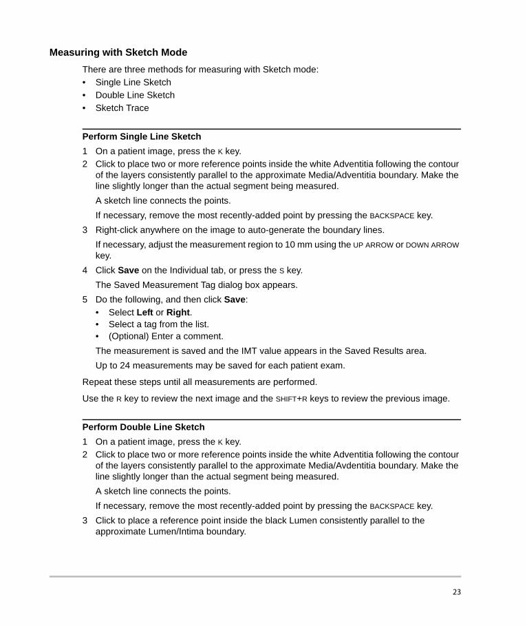
Measuring with Sketch ModeThere are three methods for measuring with Sketch mode:• Single Line Sketch• Double Line Sketch• Sketch Trace
Perform Single Line Sketch1 On a patient image, press the K key.2 Click to place two or more reference points inside the white Adventitia following the contour
of the layers consistently parallel to the approximate Media/Adventitia boundary. Make the line slightly longer than the actual segment being measured. A sketch line connects the points.If necessary, remove the most recently-added point by pressing the BACKSPACE key.
3 Right-click anywhere on the image to auto-generate the boundary lines.If necessary, adjust the measurement region to 10 mm using the UP ARROW or DOWN ARROW key.
4 Click Save on the Individual tab, or press the S key.The Saved Measurement Tag dialog box appears.
5 Do the following, and then click Save:• Select Left or Right.• Select a tag from the list.• (Optional) Enter a comment. The measurement is saved and the IMT value appears in the Saved Results area. Up to 24 measurements may be saved for each patient exam.
Repeat these steps until all measurements are performed.
Use the R key to review the next image and the SHIFT+R keys to review the previous image.
Perform Double Line Sketch1 On a patient image, press the K key.2 Click to place two or more reference points inside the white Adventitia following the contour
of the layers consistently parallel to the approximate Media/Avdentitia boundary. Make the line slightly longer than the actual segment being measured.A sketch line connects the points. If necessary, remove the most recently-added point by pressing the BACKSPACE key.
3 Click to place a reference point inside the black Lumen consistently parallel to the approximate Lumen/Intima boundary.
23

4 Click to place one or more additional reference points. Make the line slightly longer than the actual segment being measured.A second sketch line connects the points.
5 Place a point to the right of the Media/Adventitia sketch line or right-click anywhere on the image.If necessary, adjust the measurement region to 10 mm using the UP ARROW or DOWN ARROW key and by adjusting the vertical constraint lines.
6 Click Save on the Individual tab, or press the S key. The Saved Measurement Tag dialog box appears.
7 Do the following, and then click Save:• Select Left or Right.• Select a tag from the list.• (Optional) Enter a comment.The measurement is saved and the IMT value appears in the Saved Results area. Up to 24 measurements may be saved for each patient exam.
Repeat these steps until all measurements are performed.
Use the R key to review the next image and the SHIFT+R keys to review the previous image.
Perform Sketch Trace1 On a patient image, press the K key.2 Click to place reference points directly on the Media/Adventitia border of the Intima/Media
layer. Make the line slightly longer than the actual segment being measured.Do not put the points inside the Adventitia as in the other sketch modes.A sketch line connects the points.
3 Click to place reference points directly on the Lumen/Intima border of the Intima/Media layer. Place these points as precisely as possible and make the line slightly longer than the actual segment being measured.Do not put the points inside the Lumen as in the other Sketch mode methods.A sketch line connects the points. If necessary, remove the most recently-added point by pressing the BACKSPACE key.
4 Place a point to the right of the Media/Adventitia sketch line or right-click anywhere on the image.
5 If the Lumen edge requires limiting, place the cursor directly on the green Lumen constraint line at one of the edges.The line becomes brighter.
6 Move the cursor toward the cyan boundary line, and then click. A menu appears.
24

7 Select Limit Lumen Edge.8 If the Adventitia edge requires limiting, place the cursor directly on the magenta dotted
Adventitia constraint line at one of the edges.The line becomes brighter.
9 Move the cursor toward the cyan boundary line, and then click. A menu appears.
10 Select Limit Adventitia Edge.11 Move the Lumen and Adventitia constraint lines until the cyan boundary lines stabilize (at
least three pixels).12 If necessary, adjust the measurement region to 10 mm using the UP ARROW or DOWN ARROW
key and by adjusting the vertical constraint lines.13 Click Save on the Individual tab, or press the S key.
The Saved Measurement Tag dialog box appears.14 Do the following, and then click Save:
• Select Left or Right.• Select a tag from the list.• (Optional) Enter a comment.The measurement is saved and the IMT value appears in the Saved Results area on the Individual tab. Up to 24 measurements may be saved for each patient exam.
Repeat these steps until all measurements are performed.
Use the R key to review the next image and the SHIFT+R keys to review the previous image.
25

Trace ModeTrace mode defines the IMT measurement solely from the user-defined location.
Trace Measurement Lines The figure and table below show the lines available, their colors, and names as they appear for a trace measurement.
Figure 7 Trace Measurement Lines
Measuring with Trace Mode
Perform Trace1 On a patient image, press the T key. 2 Start at the left portion of the measurement region and click to place reference points on the
Media/Adventitia boundary. See Figure 8.Be sure to stay on the Media/Adventitia boundary.If too great a distance is spanned when the Media/Adventitia boundary is curving, the path will deviate from the actual border. In this case, press the BACKSPACE key and add points closer together to keep this line on the Media/Adventitia border.
Table 4: Trace Measurement Lines
Color Name
Green, with Points Traced Lumen/Intima Line
Cyan Lumen/Intima Boundary Line
Magenta, with Points Traced Adventitia Line
Cyan Media/Adventitia Boundary Line
26
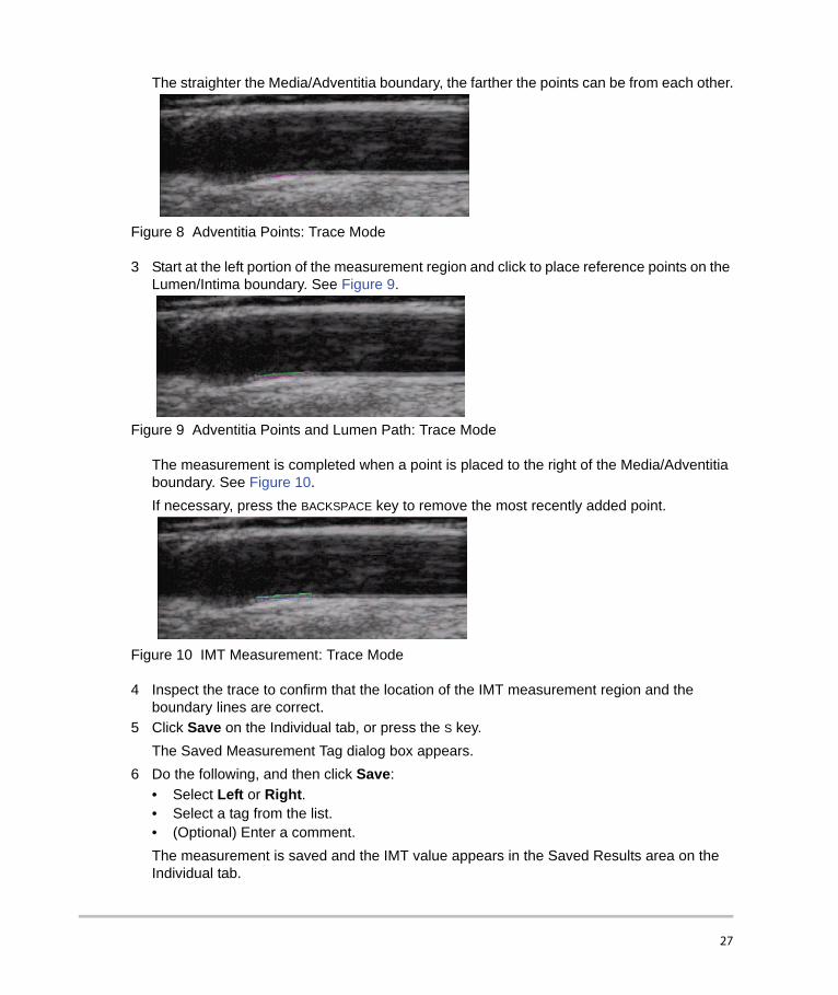
The straighter the Media/Adventitia boundary, the farther the points can be from each other.
Figure 8 Adventitia Points: Trace Mode
3 Start at the left portion of the measurement region and click to place reference points on the Lumen/Intima boundary. See Figure 9.
Figure 9 Adventitia Points and Lumen Path: Trace Mode
The measurement is completed when a point is placed to the right of the Media/Adventitia boundary. See Figure 10.If necessary, press the BACKSPACE key to remove the most recently added point.
Figure 10 IMT Measurement: Trace Mode
4 Inspect the trace to confirm that the location of the IMT measurement region and the boundary lines are correct.
5 Click Save on the Individual tab, or press the S key. The Saved Measurement Tag dialog box appears.
6 Do the following, and then click Save:• Select Left or Right.• Select a tag from the list.• (Optional) Enter a comment.The measurement is saved and the IMT value appears in the Saved Results area on the Individual tab.
27
Up to 24 measurements may be saved for each patient exam.
Repeat these steps until all measurements are performed.
Use the R key to review the next image and the SHIFT+R keys to review the previous image.
Setting a Reference PointIt may be useful to mark the location of the dilation point to be used as a distance baseline when performing IMT measurements.
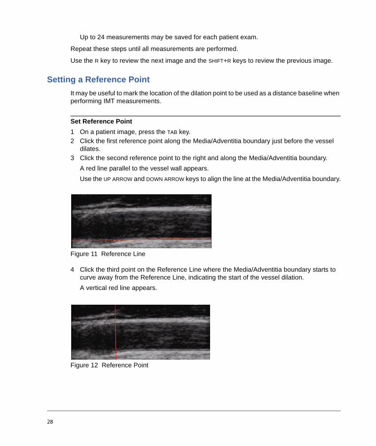
Set Reference Point1 On a patient image, press the TAB key.2 Click the first reference point along the Media/Adventitia boundary just before the vessel
dilates.3 Click the second reference point to the right and along the Media/Adventitia boundary.
A red line parallel to the vessel wall appears.Use the UP ARROW and DOWN ARROW keys to align the line at the Media/Adventitia boundary.
Figure 11 Reference Line
4 Click the third point on the Reference Line where the Media/Adventitia boundary starts to curve away from the Reference Line, indicating the start of the vessel dilation.A vertical red line appears.
Figure 12 Reference Point
28

IMT measurements performed after setting the reference point have additional measurement results. If an auto measurement is performed, information appears in the status bar: for example, “Left and Right from Reference Line-5.324, 15.324 mm” and “Center to Reference -10.324 mm.”
Changing Default IMT Measurement SettingsThe recommended width for the IMT measurement region is 10 mm.
Change Default IMT Measurement1 From the Settings menu, select Measurement Settings.2 Enter the desired width for the IMT measurement region in mm.3 Click OK.
Plaque MeasurementsThe plaque measurement tool measures a linear distance representing plaque in the carotid artery.
Current plaque measurements appear on the Individual tab in the Current Results area. For more information, see “Measurement Results” on page 30. Only one plaque measurement can be taken at a time.
A maximum of four plaque measurements can be imported from NanoMaxx, M-Turbo, or MicroMaxx ultrasound systems.
Take Plaque Measurement1 On a patient image, press the P key to activate the plaque measurement tool. 2 Click to place the first measurement point. 3 Click to place the second measurement point.
The measurement results appear in the Current Results area.4 Click Save on the Individual tab, or press the S key.
The Saved Measurement Tag dialog box appears.5 Do the following, and then click Save:
• Select Left or Right.• Select a tag from the list.• (Optional) Enter a comment.The measurement is saved and the plaque value appears in the Saved Results area. Up to 8 measurements may be saved for each patient exam.
Repeat these steps until all measurements are performed.
29
Use the R key to review the next image and the SHIFT+R keys to review the previous image.
Measurement ResultsIMT and plaque measurements can be saved into a collection of measurements displayed in the Saved Results area. These individual values as well as average values are included on the IMT report. Selected measurements can be regenerated, edited, and deleted. Measurements imported from NanoMaxx, M-Turbo, or MicroMaxx ultrasound systems can only be excluded or included in the report.
A summary of all saved results can be viewed on the Summary tab.
Selecting Saved Measurements
Select MeasurementsDo any of the following:• Click to select a single measurement.• Right-click to select a single measurement and display a pop-up menu with commands
to Regenerate, Edit, or Delete the saved measurement.• SHIFT-click to select measurements in consecutive order.• CTRL-click to select measurements that are not in consecutive order.
Regenerating MeasurementsWhen there is at least one saved measurement, that saved measurement together with the associated image can be regenerated and displayed.
The Regenerate command can be used:• To redisplay any saved measurement after the image has been cleared.• To view individual measurements that have been opened from a previously saved
measurement file.• When a measurement is regenerated and edited, a new individual measurement is created.
Regenerate Measurement1 From the Saved Results area, select the measurement.2 Click Regenerate, or right-click and select Regenerate from the pop-up menu.
The image containing the measurement appears.If the image cannot be located, a dialog box appears indicating the patient name and original location of the image.
30

Deleting Saved MeasurementsUse Delete to remove a saved measurement from a patient exam.
Delete Measurement1 From the Saved Results area, select the measurement.2 Click Delete, or right-click and select Delete from the pop-up menu.
The measurement is deleted, and the remaining saved measurements are renumbered.
Excluding Imported MeasurementsYou can exclude a saved imported measurement to keep it from being included in a patient report. Excluding a measurement does not remove it from the exam, just from the report.
By default, all measurements are included in the report. If you select to exclude a measurement from a report, it is not deleted from the results and can be reselected to include in another report. Look for an asterisk or view the print preview to verify which imported measurements are included in a report.
Exclude Measurement1 From the Imported Results area on the Imported tab, select the measurement.2 Click Exclude from Exam.
The asterisk is removed from the measurement indicating that it is not included with other measurements in the patient report. Only imported measurements with asterisks are included in the patient report.
Include Measurement1 From the Imported Results area on the Imported tab, select the measurement.2 Click Include in Exam.
The asterisk is replaced next to the measurement indicating that it will be included with other measurements in the patient report. Only imported measurements with asterisks are included in the patient report.
Editing MeasurementsThe only portions of a saved measurement that can be edited are comments and location tags.
Edit Measurement1 From the Saved Results area, select the desired measurement.2 Click Edit, or right-click and select Edit Saved Measurement Info from the pop-up menu.
31
The Saved Measurement Tag dialog box appears.3 Enter or edit comment information or location tag.4 Click OK.
Reviewing Saved Exams
Review Saved Measurements1 From the File menu, select Open Saved Exams.
The Open Saved Exam dialog box appears listing the existing patients. Groups of saved measurements are listed and identified as Measures.kpt or Measures.xml. If a previous file has been reviewed and other measurements are performed, each modified exam is stored in a new file with a new file name, for example, Measures1.kpt, Measures2.xml.
2 Select the desired file.The patient information and all saved measurements for this patient exam are opened and replace the current patient.The first measurement, 1 in the # list, is automatically regenerated and displayed on the active image, if available.If any of these saved measurements are deleted or new measurements are added, a new file is generated for this exam. The original file remains intact.To regenerate other saved measurements for this file, see “Regenerating Measurements” on page 30.
3 Click OK.
Manual CalipersManual Calipers allow you to make six linear distance measurements on an image. The results are displayed in the corresponding dialog box.
Use Manual Caliper1 Open a patient image.2 Press the M key to initiate the caliper measurement mode. 3 Click in the Active View pane to place the first measurement point.
The distance from the first point to the cursor position appears in the status bar at the bottom of SonoCalc IMT, for example, “Caliper Dist=##.### mm.”The x and y values are in pixels.
4 Click in the Active View pane to place the second measurement point. The distance between the two points appears in the Caliper Measurements dialog box.
32

A number appears next to the measurement, indicating the corresponding measurement results.To clear all distance measurements, press the ESC key.
5 Select the next caliper in the Caliper Measurements dialog box and repeat these steps, as needed.
6 Click OK to close the Caliper Measurements dialog box.
Figure 13 Two Distance Measurements
IMT ReportThe IMT report provides the average CCA Mean IMT and average CCA Max Region IMT, displays an image of the patient’s carotid artery, displays the patient’s placement as a percentile of the population, and plots the patient’s average IMT value against the population you specify.
The IMT image and measurement on the first page of the report are the current image and measurement on the screen at the time you create the report. Subsequent pages display Individual IMT measurements, average plaque measurements, and measurements transferred from NanoMaxx, M-Turbo, or MicroMaxx ultrasound systems.
Customizing Report StationeryBy default, the report has a SonoSite logo at the top. You can instead use a custom logo.
Use a Custom Logo in Reports1 Prepare the logo per these guidelines:
• BMP format• 350 by 100 pixels• 24-bit color• Filename LocationImage_350x100.bmp
2 Save the file in the \SonoCalc\ExamData\IMT Tables folder.3 Restart SonoCalc IMT.
33
Viewing IMT Report The IMT report displays the last active image. To select another image for the report, regenerate the desired image to make it the active image.
View ReportFrom the File menu, select Print or Print Preview.The IMT report appears.
Saving Report as PDF
Save Report as PDF1 On the Summary tab, click Save as, or from the File menu, select Save As PDF. The Save
As dialog box appears.2 Verify the file location and patient name.3 Click Save.
Printing Report
Print Report1 Ensure that there is at least one saved IMT measurement in the Saved Results area.2 From the File menu, select Print.3 Verify settings and the printer location.4 Click OK.
Individual and imported measurements can be included in a report if there are imported measurements available for a patient. Both individual measurements completed in SonoCalc IMT and imported measurements show on the report and are included in the averages.
Print Report with Imported Data1 Select the Imported tab.2 Exclude any measurements that you don’t want to appear in the report. See “Excluding
Imported Measurements” on page 31.The asterisk is removed from the measurement.Note: The default is for all imported measurements to appear in the report. An asterisk indicates that the measurement will appear in the report. If a measurement is selected for exclusion from the report, the asterisk is removed.
3 From the File menu, select Print.If you want to preview the report before printing, click Print Preview.
34

Note: Excluded measurements can still be included in future reports. See “Excluding Imported Measurements” on page 31.
Graph SetupThe report contains up to two graphs. The IMT graph tables list the population data used to plot the graphs. You can use the default IMT graph tables, or you can set up custom IMT graph tables. The values in the default IMT graph tables are from the research listed in “References” on page 37.
After tables are set up, you select them on the Report Configuration tab. See “Report Configuration Tab” on page 6.
View the Default IMT Graph Tables1 From the Settings list, select Plot Settings.
The IMT Graph Tables dialog box appears.2 From the Graph Title list, select a table to view:
• Average CCA Mean IMT Compared to Male Population• Average CCA Mean IMT Compared to Female Population• Average CCA Max Region IMT Compared to Male Population• Average CCA Max Region IMT Compared to Female Population
These tables display data in two decimal points regardless of the source reference data and cannot be changed or edited.
Custom IMT Graph TablesYou can set up as many as 100 custom IMT graph tables to use comparative population data not available in the default IMT graph tables. You can customize age, population percentile, and IMT measurement value.
Set Up Custom IMT Graph Table1 Close all exams and images.2 From the Settings menu, select Plot Settings.
The IMT Graph Tables dialog box appears.3 Click New Table.
The IMT Graph Tables dialog box appears.4 Enter a title in the Graph Title field.5 Under Gender, select an option.
WARNING: Prior to use, verify that custom table data entries are correct. SonoSite recommends previewing the report before using for an exam.
35

6 In the Years column, enter the ages, in consecutive order.7 Modify the percentile column heads, if desired.8 Enter IMT data in the appropriate fields.
Data must be in the allowable range between .2 and 1.400 mm.9 Click Save.10 Click OK.
Edit or Delete Custom IMT Graph Table1 From the Settings menu, select Plot Settings.
The IMT Graph Tables dialog box appears.2 In the Graph Title list, select the custom graph table to edit (default graph tables are not
selectable).3 Do one of the following:
• Click Edit, enter edits, and then click Save.• Click Delete, and then click Yes to confirm.
4 Click OK.
Exporting DataYou can export data as text or as a measurement synopsis file.
Exporting as text allows you to save the patient information and measurement data as a text file.
Exporting a measurement synopsis file archives all patient exams and measurement data in a HIPAA compliant manner (removing patient names) to a single file. You must have saved patient data to export measurements to a synopsis file.
Export as Text1 Select the file with the saved measurements you want to export.2 From the File menu, select Export as Text.3 Enter a file name.4 Select a file location.5 Click Save.
The measurements are saved as a text file.
Export Measurement Synopsis File1 From the File menu, select Export Measurement Synopsis.2 Enter a file name.3 Select a file location.4 Click Save.
36

The measurements are saved in SYN format (a custom text format).
Results SummaryStatistical information for measurements appears in the Summary Results area on the Summary tab. Summary statistics are provided for Mean IMT, Max Region IMT, and Plaque. They include the following:
ReferencesAmin Aminbakhsh, MD, G.B. John Mancini, MD. “Carotid Intima-Media Thickness Measurements: What Defines an Abnormality? A Systematic Review,” Clinical and Investigative Medicine, August 1999, 22(4):149-157.
Table 1: ARIC Study:Measurement Type: Average CCA Mean IMT over default measurement region widthAge Range: 45 to 65Mean and 75th percentile
Table 1 and 3: CHS Study:Measurement Type: Average CCA Maximum Region IMT over 1 mm segmentAge Range: 65 to 85Mean and Standard Deviation
Oren, Anath, MD, et al. “Cardiovascular Risk Factors and Increased Carotid Intima-Media Thickness in Healthy Young Adults, The Atherosclerosis Risk in Young Adults (ARYA) Study,” Archives of Internal Medicine, (2003), 163:1787-1792.
Measurement Type: Average CCA Mean IMT over default measurement region widthMean Age: 28Mean and Standard Deviation
Tonstad, Serena, et al. “Risk Factors Related to Carotid Intima-Media Thickness and Plaque in Children With Familial Hypercholesterolemia and Control Subjects,” Arteriosclerosis Thrombosis, and Vascular Biology, (1996), 16(8):984-991.
Measurement Type: Average CCA Mean IMT over default measurement region widthMean Age: 14
Average The average of all saved measurements
Min The smallest IMT measurement in the saved measurement list
Max The largest IMT measurement in the saved measurement list
37

Mean and Standard Deviation
Measurement Type: Average CCA Maximum Region IMT over 1 mm segmentMean Age: 14Mean and Standard Deviation
Tonstad, Serena, et al. “Carotid Intima-Media Thickness and Plaque in Patients with Familial Hypercholesterolaemia and Control Subjects,” European Journal Clinical Investigation, (1998), 28(12):971-979.
Measurement Type: Average CCA Mean IMT over default measurement region widthMean Age: 38Mean and Standard Deviation
Measurement Type: Average CCA Maximum Region IMT over 1 mm segmentMean Age: 38Mean and Standard Deviation
Urbina, Elaine M. “Impact of Multiple Coronary Risk Factors on the Intima-Media Thickness of Different Segments of Carotid Artery in Healthy Young Adults (The Bogalusa Heart Study),” American Journal of Cardiology, (2002), 90(9):953-958.
Measurement Type: Average CCA Max Region IMT over default measurement region widthMean Age: 32Mean and Standard Deviation
Additional Supporting References
Howard G, Sharrett AR, Heiss G, Evans GW, Chambless LE, Riley WA, et al. “Carotid Artery Intimal-Medial Thickness Distribution in General Populations As Evaluated by B-Mode Ultrasound.” ARIC Investigators. Atherosclerosis Risk in Communities. Stroke, (1993), 24:1297-1304.
O'Leary DH, Polak JF, Krommal RA, et al. “Distribution and Correlates of Sonographically Detected Carotid Artery Disease in the Cardiovascular Health Study.” CHS Collaborative Research Group. Stroke, (1992), 23:1752-1760.
O'Leary, DH, Polak JF, Krommal RA, et al. “Thickening of the Carotid Wall. A Marker for Atherosclerosis in the Elderly?”, Cardiovascular Health Study Collaborative Research Group. Stroke, (1996), 27:224-231.
Polak JF, Krommal RA, Tell GS, O'Leary DH, et al. “Compensatory Increase in the Carotid Artery Diameter. Relation to Blood Pressure and Artery IMT in Older Adults”, Stroke, (1996), 27:2012-2115.
38

Distance Measurement AccuracyThe SonoCalc IMT scaling factor error on auto-calibrated images is less than 1%. The scaling factor error on manually calibrated images depends on the user’s ability to accurately place the calibration cursors. This error is in addition to the inherent errors of the imported image.
Technical SupportFor technical support or to obtain additional license keys, contact SonoSite Technical Support as follows:
Phone: 1-877-657-8118
Fax: 425-951-6700
E-mail: [email protected]
Web: www.sonosite.com
39

40


P08450-03