Embed Size (px)
Citation preview

B>E4A486= <8G4A
DB4A 70=31>>:
<G� � � 2WP]]T[ <^Sd[Pa 1a^PSRPbc <XgX]V 3TbZ
<G� #B # 2WP]]T[ <^Sd[Pa 1a^PSRPbc <XgX]V 3TbZ
<G�?BD B^eTaTXV] ?^fTa Bd__[h
B^]XUTg ;cS� (($�&�
0[[ AXVWcb ATbTaeTS
ATeXbX^] ���Y� 0dVdbc� ((&
B^]XUTg ;cS� % � BcPcX^] A^PS� 8acW[X]VQ^a^dVW�
=^acWP]cb�� ==( $@4� 4]V[P]S�
CT[ ) �## ��� ("" %$� &��
5Pg ) �## ��� ("" %$� &!%
9^V_b]QdY_^ Y^ dXYc T_Se]U^d Yc ceRZUSd d_ SXQ^WU gYdX_ed ^_dYSU Q^T T_Uc ^_d bU`bUcU^d Q S_]]Yd]U^d _^ dXU `Qbd _V dXU fU^T_b�
C_^YVUh <dT cXQ\\ ^_d RU \YQR\U V_b Q^i \_cc _b TQ]QWU gXQdc_UfUb QbYcY^W Vb_] dXU ecU _V Y^V_b]QdY_^ _b Q^i Ubb_b S_^dQY^UT Y^ dXYc
]Q^eQ\�
>_ `Qbd _V dXYc ]Q^eQ\ ]Qi RU bU`b_TeSUT _b dbQ^c]YddUT Y^ Q^i V_b] _b Ri Q^i ]UQ^c� U\USdb_^YS _b ]USXQ^YSQ\� Y^S\eTY^W
`X_d_S_`iY^W� bUS_bTY^W� _b Y^V_b]QdY_^ cd_bQWU Q^T bUdbYUfQ\ cicdU]c� V_b Q^i `eb`_cU _dXUb dXQ^ dXU `ebSXQcUb�c `Ubc_^Q\ ecU�
gYdX_ed dXU Uh`bUcc gbYddU^ `Ub]YccY_^ _V C_^YVUh <dT�
E^\Ucc _dXUbgYcU ^_dUT� Q\\ ^Q]Uc _V S_]`Q^YUc� `b_TeSdc Q^T `Ubc_^c S_^dQY^UT XUbUY^ QbU `Qbd _V Q S_]`\UdU\i VYSdYdY_ec QTQ`dQdY_^
Q^T QbU TUcYW^UT c_\U\i d_ T_Se]U^d dXU ecU _V C_^YVUh `b_TeSdc�
2^]cT]cb
FPaaP]ch 0]S BPUTch 8]U^a\PcX^] ��������������������������������������������������������������� X
FPaaP]ch ATVXbcaPcX^] �������������������������������������������������������������������������������������������������������X
B^eTaTXV] <XgX]V 2^]b^[Tb����������������������������������������������������������������������������������������������XGQbbQ^di 4UdQY\c �����������������������������������������������������������������������������������������������������������������Y
BPUTch >U <PX]b >_TaPcTS 4`dX_\T]c �����������������������������������������������������������������������������XX
B^eTaTXV] <XgX]V 2^]b^[T������������������������������������������������������������������������������������������������XX@bU`QbY^W dXU =QSXY^U V_b EcU �������������������������������������������������������������������������������������������YY
<G�?BD ?^fTa Bd__[h D]Xc����������������������������������������������������������������������������������������������XX5aeY`]U^d CQVUdi����������������������������������������������������������������������������������������������������������������YY
F_\dQWU CUddY^W 3XUS[c�������������������������������������������������������������������������������������������������������YYY
@_gUb 3QR\U Q^T 3_^^USdY_^ ���������������������������������������������������������������������������������������������YYY
6ecU BQdY^W�������������������������������������������������������������������������������������������������������������������������YYY
BU]_fY^W dXU 3_fUbc _V dXU @_gUb Ce``\i������������������������������������������������������������������������YYY
<Y]YdQdY_^ _V <YQRY\Ydi ������������������������������������������������������������������������������������������������������������Yf
� 8]ca^SdRcX^] ��������������������������������������������������������������������������������������������� �
� � 8]ca^SdRcX^]����������������������������������������������������������������������������������������������������������������� �
!�!�!� 6UQdebUc��������������������������������������������������������������������������������������������������������������������!�!
!�!�"� =_Te\U 6UQdebUc�������������������������������������������������������������������������������������������������������!�!
!�!�"�! =YS�<Y^U 9^`ed =_Te\U �������������������������������������������������������������������������������������������!�"
!�!�"�" 4eQ\ CdUbU_ 9^`ed =_Te\U��������������������������������������������������������������������������������������!�"
!�!�"�# DU\S_ 9^`ed =_Te\U������������������������������������������������������������������������������������������������!�"
!�!�"�$ DbQ^c]YccY_^ B_edUb =_Te\U ��������������������������������������������������������������������������������!�"
!�!�"�% ?edcYTU C_ebSU CU\USd =_Te\U������������������������������������������������������������������������������!�#
!�!�"�& =QcdUb =_^Yd_b Q^T ?ed`ed =_Te\U �����������������������������������������������������������������������!�#
!�!�"�' =UdUb 2bYTWU����������������������������������������������������������������������������������������������������������!�#
�!� 8]bcP[[PcX^] =^cTb �������������������������������������������������������������������������������������������������������� �#
!�"�!� 1d]_c`XUbU���������������������������������������������������������������������������������������������������������������!�$
!�"�"� 5\USdb_]QW^UdYS BQTYQdY_^ ����������������������������������������������������������������������������������������!�$
!�"�#� 4Y]U^cY_^c Q^T 3ed�?ed CYjUc���������������������������������������������������������������������������������!�$
!�"�$� =_Te\U 3_^VYWebQdY_^������������������������������������������������������������������������������������������������!�%
�"� 2^]]TRc^ab P]S 2PQ[X]V �������������������������������������������������������������������������������������������� �%!�#�!� H<B # @Y^ 3_^^USd_bc ����������������������������������������������������������������������������������������������!�&
!�#�"� !�$³ ´1µ 7QeWU CdUbU_ :QS[ @\eWc����������������������������������������������������������������������������!�&
!�#�#� 4�Di`U 3_^^USd_bc ��������������������������������������������������������������������������������������������������!�'
�#� BhbcT\ 1[^RZ 3XPVaP\����������������������������������������������������������������������������������������������� �'
!� <XR�;X]T 8]_dc <^Sd[T����������������������������������������������������������������������������� !�
!� � ?P]T[ 2^]ca^[b�������������������������������������������������������������������������������������������������������������!�
"�!�!� 3_ebcU 7QY^ 1TZecd]U^d�������������������������������������������������������������������������������������������"�!
"�!�"� =YS�<Y^U CU\USd 2edd_^ ����������������������������������������������������������������������������������������������"�!
"�!�#� ?ed`ed CU\USd ������������������������������������������������������������������������������������������������������������"�!
"�!�$� 5aeQ\YcQdY_^���������������������������������������������������������������������������������������������������������������"�!
"�!�%� 5A 5^QR\U 2edd_^ �����������������������������������������������������������������������������������������������������"�!
"�!�&� DbY] ;^_R �����������������������������������������������������������������������������������������������������������������"�!
"�!�'� @Q^ ;^_R ������������������������������������������������������������������������������������������������������������������"�!
"�!�(� @bU�6QTU <YcdU^ � @6< � 2edd_^���������������������������������������������������������������������������������"�"
"�!�)� ?^ 2edd_^������������������������������������������������������������������������������������������������������������������"�"
"�!�! � 6QTUb�����������������������������������������������������������������������������������������������������������������������"�"
"�!�!!� CSbQdSX @QT ������������������������������������������������������������������������������������������������������������"�"
!�!� ATPa ?P]T[ �������������������������������������������������������������������������������������������������������������������!�"
"�"�!� BU]_dU 3_^^USd_b����������������������������������������������������������������������������������������������������"�#
"�"�"� =YS 9^ 3_^^USd_b�������������������������������������������������������������������������������������������������������"�#
"�"�#� <Y^U 9^ 3_^^USd_b������������������������������������������������������������������������������������������������������"�#
!�"� <^Sd[T >_cX^]b P]S 9d\_Ta BTccX]Vb����������������������������������������������������������������������!�#"�#�!� Ce]]Qbi _V :e]`Ub CUddY^Wc V_b =YS�<Y^U =_Te\U ���������������������������������������������������"�$
"�#�"� EcY^W Q @XQ^d_] @_gUbUT =YSb_`X_^U �������������������������������������������������������������������"�%
"�#�#� 5^QR\U <6 BUc`_^cU _^ =YS 9^`ed����������������������������������������������������������������������������"�%
"�#�$� CU\USd BU]_dU CdQbd�Cd_` V_b =YS _b <Y^U������������������������������������������������������������������"�%
"�#�%� 5^QR\U 3_^dY^e_ec =_]U^dQbi CdQbd 6b_] ?^ 2edd_^ ���������������������������������������������"�%
"�#�&� CdQbd CU\USd � =_]U^dQbi _b <QdSXUT�����������������������������������������������������������������������"�%
"�#�'� Cd_` CU\USd � ?^ 6QTUb 4_g^� _b GYdX 2edd_^ E` ����������������������������������������������������"�%
"�#�(� =_^Yd_b =edU CU\USd � CdeTY_ _b 3_^db_\ B__] ���������������������������������������������������������"�&
"�#�)� CUd d_ CdQbd dXU DY]Ub 1ed_]QdYSQ\\i �������������������������������������������������������������������������"�&
"�#�! � 4YcQR\U dXU BU]_dU Cd_` 6e^SdY_^ �������������������������������������������������������������������������"�&
"�#�!!� 5^QR\U dXU 1ed_]QdYS @bU�VQTU <YcdU^ 6QTUb 3Q^SU\����������������������������������������������"�&
!�#� 0__[XRPcX^]b ����������������������������������������������������������������������������������������������������������������!�&"�$�!� 3_^db_\\Y^W Q =YS�<YfU 4Yc`\Qi�����������������������������������������������������������������������������������"�'
"�$�"� 5^QR\Y^W DQ\[RQS[ 2UdgUU^ CdeTY_c�������������������������������������������������������������������������"�'
"�$�#� CUddY^W dXU 3_eWX CgYdSX������������������������������������������������������������������������������������������"�'
"�$�$� 1\\_gY^W dXU CdeTY_ 7eUcd d_ dQ\[ d_ Q DU\U`X_^U 3Q\\Ub � DU\S_ DQ\[RQS[ � "�(
"� 3dP[ BcTaT^ ;X]T 8]_dc <^Sd[T ��������������������������������������������������������������� "�
"� � ?P]T[ 2^]ca^[b�������������������������������������������������������������������������������������������������������������"�
#�!�!� 3_ebcU 7QY^ 1TZecd]U^d�������������������������������������������������������������������������������������������#�!
#�!�"� 9^`ed !�9^`ed " CU\USd 2edd_^�������������������������������������������������������������������������������������#�!
#�!�#� ?ed`ed CU\USd ������������������������������������������������������������������������������������������������������������#�!
#�!�$� 5aeQ\YcQdY_^ � ?`dY_^Q\ ���������������������������������������������������������������������������������������������#�!
#�!�%� 5A 5^QR\U 2edd_^ � ?`dY_^Q\ � ����������������������������������������������������������������������������������#�!
#�!�&� DbY] ;^_R �����������������������������������������������������������������������������������������������������������������#�!
#�!�'� 2Q\ ;^_R��������������������������������������������������������������������������������������������������������������������#�!
#�!�(� @bU�6QTU <YcdU^ � @6< � 2edd_^���������������������������������������������������������������������������������#�"
#�!�)� ?^ 2edd_^������������������������������������������������������������������������������������������������������������������#�"
#�!�! � 6QTUb�����������������������������������������������������������������������������������������������������������������������#�"
#�!�!!� CSbQdSX @QT ������������������������������������������������������������������������������������������������������������#�"
"�!� ATPa ?P]T[ �������������������������������������������������������������������������������������������������������������������"�"
#�"�!� BU]_dU 3_^^USd_b����������������������������������������������������������������������������������������������������#�#
#�"�"� <UVd 9^`ed 3_^^USd_b �������������������������������������������������������������������������������������������������#�#
#�"�#� BYWXd 9^`ed 3_^^USd_b�����������������������������������������������������������������������������������������������#�#
"�"� <^Sd[T >_cX^]b P]S 9d\_Ta BTccX]Vb����������������������������������������������������������������������"�##�#�!� Ce]]Qbi _V :e]`Ub CUddY^Wc V_b 4eQ\ CdUbU_ <Y^U 9^`ed =_Te\U�����������������������������#�$
#�#�"� CU\USd BU]_dU CdQbd�Cd_` V_b <Y^U 9^`ed ! _b " ���������������������������������������������������������#�%
#�#�#� 5^QR\U 3_^dY^e_ec =_]U^dQbi CdQbd 6b_] ?^ 2edd_^ ���������������������������������������������#�%
#�#�$� CdQbd CU\USd � =_]U^dQbi _b <QdSXUT�����������������������������������������������������������������������#�%
#�#�%� Cd_` CU\USd � ?^ 6QTUb 4_g^� _b GYdX 2edd_^ E` ����������������������������������������������������#�%
#�#�&� CUd d_ CdQbd dXU DY]Ub 1ed_]QdYSQ\\i �������������������������������������������������������������������������#�%
#�#�'� 4YcQR\U dXU BU]_dU Cd_` 6e^SdY_^ ���������������������������������������������������������������������������#�%
#�#�(� 3Q^SU\ dXU 1ed_]QdYS @bU�VQTU <YcdU^ ����������������������������������������������������������������������#�%
#�#�)� 7QY^ 1TZecd]U^d V_b 9^`ed " ��������������������������������������������������������������������������������������#�&
#�#�! � EcY^W dXU ?`dY_^Q\ 7bQ] 1]`\YVYUb �������������������������������������������������������������������������#�&
#� CT[R^ <^Sd[T ������������������������������������������������������������������������������������������� #�
#� � ?P]T[ 2^]ca^[b�������������������������������������������������������������������������������������������������������������#�
$�!�!� 3_ebcU 7QY^ 1TZecd]U^d�������������������������������������������������������������������������������������������$�!
$�!�"� ?ed`ed CU\USd ������������������������������������������������������������������������������������������������������������$�!
$�!�#� 5aeQ\YcQdY_^���������������������������������������������������������������������������������������������������������������$�!
$�!�$� 5A 5^QR\U 2edd_^ �����������������������������������������������������������������������������������������������������$�!
$�!�%� DbY] ;^_R �����������������������������������������������������������������������������������������������������������������$�!
$�!�&� @Q^ ;^_R ������������������������������������������������������������������������������������������������������������������$�!
$�!�'� @bU�6QTU <YcdU^ � @6< � Q^T DQ\[RQS[ � D�2 � 2edd_^ �����������������������������������������������$�!
$�!�(� 8_\T 2edd_^ ���������������������������������������������������������������������������������������������������������������$�"
$�!�)� 6QTUb�������������������������������������������������������������������������������������������������������������������������$�"
$�!�! � CSbQdSX @QT ������������������������������������������������������������������������������������������������������������$�"
#�!� ATPa ?P]T[ �������������������������������������������������������������������������������������������������������������������#�"
$�"�!� BU]_dU 3_^^USd_b����������������������������������������������������������������������������������������������������$�#
$�"�"� <Y^U 9^`ed 3_^^USd_b�������������������������������������������������������������������������������������������������$�#
$�"�#� 3\UQ^�6UUT ?ed`ed 3_^^USd_b����������������������������������������������������������������������������������$�#
#�"� <^Sd[T >_cX^]b P]S 9d\_Ta BTccX]Vb����������������������������������������������������������������������#�#$�#�!� Ce]]Qbi _V :e]`Ub CUddY^Wc V_b DU\S_ =_Te\U��������������������������������������������������������$�$
$�#�"� 4YfUbd CU\USd � =_]U^dQbi _b <QdSXUT ���������������������������������������������������������������������$�$
$�#�#� 3\UQ^�6UUT 2ec ?ed`ed CU\USd ���������������������������������������������������������������������������������$�%
$�#�$� CUd d_ CdQbd dXU DY]Ub 1ed_]QdYSQ\\i �������������������������������������������������������������������������$�%
$�#�%� 3Q^SU\ dXU 1ed_]QdYS @bU�VQTU <YcdU^ ����������������������������������������������������������������������$�%
#�#� 0SSXcX^]P[ >_cX^]b������������������������������������������������������������������������������������������������������#�$
#�$� 0__[XRPcX^]b ����������������������������������������������������������������������������������������������������������������#�%$�%�!� 3_^^USdY^W Q DU\U`X_^U 2Q\Q^SU E^Yd � 8iRbYT � �����������������������������������������������������$�&
$�%�"� 3_^VYWebY^W DQ\[RQS[ d_�Vb_] dXU 3Q\\Ub �������������������������������������������������������������������$�&
$� CaP]b\XbbX^] A^dcTa <^Sd[T ����������������������������������������������������������������� $�
$� � ?P]T[ 2^]ca^[b�������������������������������������������������������������������������������������������������������������$�
%�!�!� C_ebSU CU\USd 2edd_^c ����������������������������������������������������������������������������������������������%�!
%�!�"� =UdUb CU\USd��������������������������������������������������������������������������������������������������������������%�!
$�!� ATPa ?P]T[ �������������������������������������������������������������������������������������������������������������������$�!%�"�!� <UVd DbQ^c]YccY_^ ?ed`ed������������������������������������������������������������������������������������������%�"
%�"�"� BYWXd DbQ^c]YccY_^ ?ed`ed ���������������������������������������������������������������������������������������%�"
%�"�#� DbQ^c]YccY_^ 9^`ed ���������������������������������������������������������������������������������������������������%�"
$�"� 8]bcP[[X]V cWT <^Sd[T ��������������������������������������������������������������������������������������������������$�"
%� >dcbXST B^daRT BT[TRc <^Sd[T ��������������������������������������������������������������� %�
%� � ?P]T[ 2^]ca^[b�������������������������������������������������������������������������������������������������������������%�
&�!�!� ?edcYTU C_ebSU CU\USd 2edd_^c���������������������������������������������������������������������������������&�!
%�!� ATPa ?P]T[ � 2^]]TRcX^]b�����������������������������������������������������������������������������������������%�!
&�"�!� 3ed�?ed 6_b 3QR\Uc���������������������������������������������������������������������������������������������������&�"
&�"�"� 3_^^USdY_^c V_b =QY^ 2_QbT �������������������������������������������������������������������������������������&�"
&�"�"�! 2Q^[ ! 9^`edc ��������������������������������������������������������������������������������������������������������&�"
&�"�"�" ?ed`edc ������������������������������������������������������������������������������������������������������������������&�#
&�"�"�# 2Q^[ " 9^`edc ��������������������������������������������������������������������������������������������������������&�#
&� <PbcTa >dc_dc P]S <^]Xc^a <^Sd[T ������������������������������������������������������� &�
&� � >dc_dcb ������������������������������������������������������������������������������������������������������������������������&�!'�!�!� =QcdUb ?ed`ed 6QTUbc � ?`dY_^Q\ �����������������������������������������������������������������������������'�"
'�!�"� =_^_ 6UUT ?ed`ed CU\USdY_^ ������������������������������������������������������������������������������������'�"
'�!�#� 41 ?ed`edc ���������������������������������������������������������������������������������������������������������������'�"
&�!� <TcTa 5^[[^f BT[TRcX^]�����������������������������������������������������������������������������������������������&�!
&�"� BcdSX^ <^]Xc^a P]S ?W^]Tb BT[TRcX^]����������������������������������������������������������������������&�"'�#�!� CdeTY_ 9^`ed CU\USdY_^ �����������������������������������������������������������������������������������������������'�#
'�#�"� CdeTY_ =_^Yd_b CU\USdY_^ �������������������������������������������������������������������������������������������'�#
'�#�#� CdeTY_ @X_^Uc CU\USdY_^�������������������������������������������������������������������������������������������'�#
&�#� 2^]ca^[ A^^\ <^]Xc^a P]S ?W^]Tb BT[TRcX^]���������������������������������������������������������&�#
'�$�!� 3_^db_\ B__] 9^`ed CU\USdY_^ �����������������������������������������������������������������������������������'�$
'�$�"� 3_^db_\ B__] =_^Yd_b CU\USdY_^ �������������������������������������������������������������������������������'�$
'�$�#� 3_^db_\ B__] @X_^Uc CU\USdY_^�������������������������������������������������������������������������������'�$
'�$�$� 3_^db_\ B__] @X_^Uc C_S[Ud ����������������������������������������������������������������������������������'�%
&�$� ATPa ?P]T[ �������������������������������������������������������������������������������������������������������������������&�%
'�%�!� 43 @_gUb������������������������������������������������������������������������������������������������������������������'�&
'�%�"� ?ed`ed 3_^^USdY_^c ��������������������������������������������������������������������������������������������������'�&'�%�"�! =QY^ ?ed`ed ! * 41 ?ed`edc� =_^_ ?ed`ed � BU]_dU�������������������������������������������'�&
'�%�"�" =QY^ ?ed`ed " * 41 ?ed`edc Q^T BU]_dU��������������������������������������������������������������'�'
'�%�"�# =QcdUb 1 Q^T 2� <UVd Q^T BYWXd ?ed`edc����������������������������������������������������������������'�'
'�%�#� =_^Yd_bY^W 3_^^USdY_^c ��������������������������������������������������������������������������������������������'�''�%�#�! 5hdUb^Q\ 9^`edc � CdeTY_ Q^T 3_^db_\ B__] ����������������������������������������������������������'�'
'�%�#�" =_^Yd_b Q^T @X_^Uc � CdeTY_ Q^T 3_^db_\ B__] ��������������������������������������������������'�(
'�%�#�# D�2 9^ � 3_^db_\ B__] �������������������������������������������������������������������������������������������'�(
'�%�#�$ D�2 ?ed � CdeTY_ ����������������������������������������������������������������������������������������������������'�(
&�%� <^Sd[T >_cX^]b P]S 9d\_Ta BTccX]Vb����������������������������������������������������������������������&�('�&�!� ?ed`ed 2_QbTc�����������������������������������������������������������������������������������������������������������'�)
'�&�!�! ?ed`ed 2_QbT 1������������������������������������������������������������������������������������������������������'�)
'�&�!�" ?ed`ed 2_QbT 2������������������������������������������������������������������������������������������������������'�)
'�&�!�# BUTeSY^W 3b_cc�dQ\[ _^ dXU DU\S_ =_Te\U ������������������������������������������������������������'�!
'�&�!�$ 3_^VYWebY^W dXU 4YcdbYRedY_^ 1]`\YVYUb ?ed`edc ������������������������������������������������������'�!
'�&�"� =_^Yd_b 2_QbTc����������������������������������������������������������������������������������������������������������'�!
'�&�"�! CdeTY_ =_^Yd_b �������������������������������������������������������������������������������������������������������'�!
'�&�"�" 3_^db_\ B__] � 3B � =_^Yd_b ���������������������������������������������������������������������������������'�!!
'�&�"�# 9^XYRYdY^W Q^T 5^QR\Y^W DQ\[RQS[ ��������������������������������������������������������������������������'�!!
&�&� 0__[XRPcX^]b ����������������������������������������������������������������������������������������������������������������&� !'�'�!� 3_^db_\\Y^W Q^ ?^�1Yb <Q]` ��������������������������������������������������������������������������������������'�!"
'� <TcTa�1aXSVT �������������������������������������������������������������������������������������������� '�
'� � <TcTab���������������������������������������������������������������������������������������������������������������������������'�
'�!� 3XVXcP[ CX\Ta ����������������������������������������������������������������������������������������������������������������'�
'�"� B_TPZTa P]S 2^]ca^[b�������������������������������������������������������������������������������������������������'�!
(� B_TRXUXRPcX^]b������������������������������������������������������������������������������������������ (�
(� � CTRW]XRP[ B_TRXUXRPcX^]b��������������������������������������������������������������������������������������������(� )�!�!� 9^`ed�?ed`ed 9]`UTQ^SUc �����������������������������������������������������������������������������������������)�!
)�!�"� 6bUaeU^Si BUc`_^cU �����������������������������������������������������������������������������������������������)�!
)�!�#� >_YcU � " 8j d_ " [8j � �������������������������������������������������������������������������������������������)�!
)�!�$� 4Ycd_bdY_^�������������������������������������������������������������������������������������������������������������������)�!
)�!�%� 3b_ccdQ\[�������������������������������������������������������������������������������������������������������������������)�!
)�!�&� 5A�����������������������������������������������������������������������������������������������������������������������������)�!
)�!�'� 3_]]_^ =_TU BUZUSdY_^ BQdY_ ��������������������������������������������������������������������������������)�!
(�!� 2^]]TRcX^]b ����������������������������������������������������������������������������������������������������������������(�!
(�"� 4`dX_\T]c Ch_T����������������������������������������������������������������������������������������������������������(�!
�� 6[^bbPah������������������������������������������������������������������������������������������������� ��
8]STg ������������������������������������������������������������������������������������������������������������ 8�

FPaaP]ch P]S BPUTch 8]U^a\PcX^] ?PVT X
C_fUbUYW^ EcUb�c 7eYTU
FPaaP]ch�0]S�BPUTch�8]U^a\PcX^]
FPaaP]ch ATVXbcaPcX^]
B^eTaTXV] <XgX]V 2^]b^[Tb
FPaaP]ch 3TcPX[b
This Sovereign range of audio equipment is guaranteed for 12 months from the dateof purchase.
The components and materials used are guaranteed against defects and faultyworkmanship. Sonifex undertake to replace or repair faulty items at its discretion, within the warrantyperiod, on a return to factory basis.
In order to register the date of purchase so that we can keep you informed of anydesign inprovements or modifications, it is important to complete the WARRANTYREGISTRATION DOCUMENT and return it to :-
Sonifex Ltd,61, Station Road,Irthlingborough,Northants.,NN9 5QEENGLAND
The registration document carries the following information for servicing :-
SOVEREIGN TYPE ___________SERIAL NUMBER MX________VOLTAGE V__________

?PVT XX FPaaP]ch P]S BPUTch 8]U^a\PcX^]
C_fUbUYW^ EcUb�c 7eYTU
BPUTch >U <PX]b >_TaPcTS 4`dX_\T]c
B^eTaTXV] <XgX]V 2^]b^[T
?aT_PaX]V cWT <PRWX]T U^a DbT
Each Sovereign is shipped with a separate power supply in protective packaging andshould be inspected for damage before use. Where an item is found to have transit damage, notify thecarrier immediately with all the relevant details of the shipment. Packing materials should be kept forinspection.
<G�?BD ?^fTa Bd__[h D]Xc
The MX-PSU is a 2U high rack-mount unit which can supply +15V, -15V and+48V to either the MX10 or MX14S mixer. A lead with an IP40 678 series 7 way plug on each end isused to connect the power supply to the mixer.
The power supply should be installed where there is adequate ventilation for heat tocirculate from the rear of the unit. The mixer has a heat-sink attached to the rear panel which radiatessome heat.
Three LED’s on the front of the unit indicate whether the power to the three voltagerails is being supplied correctly. If one of the LED’s fails, then there is a problem with the powersupply unit.
4`dX_\T]c BPUTch
This equipment has been designed to meet the safety regulations currently advisedin the country of purchase.
It is important to connect the mains supply in accordance with the informationgiven. Ensure that the rear panel mains voltage statement on the separate power supply indicates thatyour equipment is suitable for your mains supply voltage and that the mains supply fuse is correctlyrated. The fuse as supplied is correct for the voltage setting.
The power cable supplied carries an EARTH conductor which is connectedinternally to the equipment chassis ground. This connection through a properly wired powerconnector is essential for safe operation. Disconnection of this earth connection may render theequipment unsafe, with a consequential possible electrical shock hazard from exposed metallic parts.
FPaaP]ch P]S BPUTch 8]U^a\PcX^] ?PVT XXX
C_fUbUYW^ EcUb�c 7eYTU
This equipment will operate in a horizontal position.
This equipment conforms to the safety regulations specified by use of the CE Mark.
Warning : Always switch the power supply off before connecting ordisconnecting the console power supply cable, removing or repairing modules and servicing.
E^[cPVT BTccX]V 2WTRZb
The rear panel of the equipment carries the Serial Number of the machine. Theoperating voltage of the Sovereign power supply is selectable at the fuse carrier on the power inlet portof the MX-PSU unit. Ensure that the machine operating voltage is correct for your mains powersupply. The safety specification of your Sovereign power supply complies with local requirements andmust be earthed through the mains connector. The available voltage settings are : -
110V Code A220V Code E240V Code U
?^fTa 2PQ[T P]S 2^]]TRcX^]
The IEC power connector or power lead provided must be connected as follows. Themains lead wires supplied with the equipment are coloured in accordance with the following code : -
Green - EarthBlue - NeutralBrown - Live
As the colours of the wires in the mains lead may not correspond with the colouredmarkings identifying the terminals of your plug, proceed as follows :-
Green and Yellow wire - must be connected to the terminal marked with E the colour green orgreen- yellow. Blue wire - must be connected to the terminal marked N or coloured black. Brown wire - must be connected to the terminal marked L or coloured red.
5dbT APcX]V
The Sovereign MX-PSU is supplied with a single fuse in the live conducting path ofthe power infeed at the power supply. ( A spare fuse is also contained in the fuse-holder housing. Forreasons of safety it is important that the correct rating and type of fuse is used. Incorrectly rated fusescould present a possible fire hazard, under equipment fault conditions. The fuse ratings for Sovereignare :-
Country code A 110 V operation - 2.0A 5 x 20mm SBCountry code E 220/240 V operation - 1.0A 5 x 20mm SB
AT\^eX]V cWT 2^eTab ^U cWT ?^fTa Bd__[h
WARNING : The power must be switched off at the supply or the power lead mustbe disconnected before attempting to remove the panels or cover. Removal of the panels and cover canexpose dangerous voltages. The cover is connected to the chassis ground of the equipment by meansof fixing screws. It is essential to maintain this earth-ground connection to maintain a safe operatingenvironment. In addition, to provide an Electromagnetic Shield, contact between the cover and thechassis must be maintained when in use.
?PVT Xe FPaaP]ch P]S BPUTch 8]U^a\PcX^]
C_fUbUYW^ EcUb�c 7eYTU
;X\XcPcX^] ^U ;XPQX[Xch
Limited Warranty - Sonifex warrants that the Sovereign hardware will be free fromdefects in materials and workmanship under normal use and service for a period of one year from thedate of receipt. Any implied warranties on the hardware are limited to one (1) year, respectively, orthe shortest period permitted by applicable law, whichever is greater.
Customer Remedies - Sonifex's entire liability and your exclusive remedy shall be, atSonifex's option, either (a) return of the price paid or (b) repair or replacement of the hardware thatdoes not meet Sonifex's Limited Warranty and which is returned to Sonifex with a copy of yourreceipt or invoice. This Limited Warranty is void if failure of the hardware has resulted from accident,abuse, or misapplication. Any replacement hardware will be warranted for the remainder of theoriginal warranty period or 30 days, whichever is longer.
No other warranties - To the maximum extent permitted by applicable law, Sonifexdisclaims all other warranties, either express or implied, including but not limited to impliedwarranties or merchantability and fitness for a particular purpose, with respect to the Sovereign, theaccompanying product manual(s) and written materials, and any accompanying hardware. TheLimited Warranty contained herein gives you specific legal rights.
No Liability for Consequential Damages - To the maximum extent permitted byapplicable law, Sonifex and its suppliers shall not be liable for any other damages whatsoever(including, without limitation, damages for loss of business profits, business interruption, loss ofbusiness information, or other pecuniary loss) arising out of the use of or inability to use this Sonifexproduct, even if Sonifex has been advised of the possibility of such damages. In any case, Sonifex'sentire liability under any provision of this agreement shall be limited to the amount actually paid byyou for the Sovereign. This Agreement is governed by the laws of England.
Sonifex Ltd can not be held liable for any loss of audio output due to equipment failure.
8]ca^SdRcX^] � 8]bcP[[PcX^] ?PVT �
C_fUbUYW^ EcUb�c 7eYTU
� 8]ca^SdRcX^]
� � 8]ca^SdRcX^]Sovereign is a range of modular mixing consoles designed for local radio stations
and self-op studios. With VCA's controlled by faders, two main output groups, built-in 4 way stereodistribution amplifier and optional script space, Sovereign offers the flexibility of larger consoles at areduced price.
Sovereign mixers are available in two frame sizes : the MX10, which can contain 10input modules and the MX14S which has room for 14 input modules plus a 7 module script space ( or21 modules in total ).
Each console has an additional output module to the far right which controls themonitoring, pre-fade listen and talkback functions together with the output selection of the twogroups. The output module can optionally contain master faders for production use. The meter bridgecontains a speaker, a digital timer and either VU or PPM meters.
The modular approach to the design means that module replacement, or expansionof the system can be carried out quickly and efficiently. All modules are internally connected by astrong bus cable which clips into place - removal of the cable and two screws allows any input moduleto be removed. Easy access is provided at the rear of the unit for all connections.
Despite the low price of the consoles, innovative design techniques and the selectionof quality components have ensured that top audio performance is produced. The use of VCA'scontrolled by the fader operation ensures tight stereo tracking and eliminates mechanical andelectronic noise. ALPS long throw faders give a smooth, repeatable response and the XLR Neutrikconnectors used are an industry standard.
Each unit is supplied complete with power supply which provides +15V, -15V and+48V to the console.
� � � 5TPcdaTb
• Fully modular build with two different frame sizes available.• Optional script space.• Built-in 4 way stereo Distribution Amplifier.• True cleanfeed output on each telco input.• ALPS faders controlling VCA operation.• VU metering or optional PPM's.• Optional Production Output module with master faders.• Digital timer, custom assignable to specific input modules.• Control room and studio monitor muting.• Two output groups.• Mono output feed.• Optional gram amp for dual stereo module.
� �!� <^Sd[T 5TPcdaTb
There are four different input modules available for installation in the mixer as wellas a blank module and Script space. The Output module controls the monitoring and master outputfunctions, and a meter bridge is used to house the meters, a speaker and the digital timer.
The modules are each covered in a separate section of this handbook, but a summaryfollows :
?PVT �! 8]ca^SdRcX^] � 8]bcP[[PcX^]
C_fUbUYW^ EcUb�c 7eYTU
� �!� <XR�;X]T 8]_dc <^Sd[T
The Mic/Line Input module is a mono input controlled by a button switch to selecteither Mic or Mono Line. Equalization is fitted as standard on this module and is enabled by the EQbutton, providing ± 7.5dB at HF ( 8kHz ) and LF ( 100Hz ). The Mic input has a jumper selectablehigh pass filter to remove low frequency intrusions and a Pan control is also available to facilitatestereo imaging.
Module gain is coarse set with preset multi-turn controls recessed at the top of themodule - the gain is trimmed with a panel Trim knob providing ± 15dB of gain. The module has aPre Fade Listen facility that is automatically disabled when the fader is opened. The module is held ina mute status until the channel On button is pressed and the fader is opened.
There are logic remote input controls for Mic Cough muting and external ReverseTalkback, with output controls to start and stop by fader or by using the On button. The remoteoutputs are connected to a 9 way D type and are fed from NPN opto-isolators. The Mic moduleprovides a jumper selectable output to facilitate either Control Room or Studio Monitor muting withjumper selectable Timer remote start.
� �!�! 3dP[ BcTaT^ 8]_dc <^Sd[T
Each module has dual switchable stereo line inputs with optional EQ. Input 1 ismade on balanced XLR connectors with gain adjustable from the front panel. Input 2 can be hard-wired on the Remote connector and has gain adjustable by Preset potentiometers on the PCB. Remotecontrol can be used for Remote Start and Stop.
This module shares many features with the Mic/Line module except for thefollowing differences : It has two stereo inputs instead of two mono inputs, the pan control is replacedby a balance control for small adjustments to the stereo image, and there is no EQ and Cough orReverse Talkback remotes.
The remote output operation can be jumper configured to be either momentary (about half a second ) or latched, to give a continuous output - a feature that may be required for sometypes of turntables.
An optional RIAA equalised gram amplifier is available for this module for use withturntables.
� �!�" CT[R^ 8]_dc <^Sd[T
This module controls the connection to the telephone balance unit and has EQ,coarse and fine gain control, PFL and A & B output select. It has only one mono input, the otherXLR connector being used for the cleanfeed output to the telephone hybrid. This output is a truecleanfeed ( not mix minus ) which consequently prevents phasing problems. The presenter can talkoff-air with a caller whilst the programme is being output.
The bus system allows for two cleanfeed signals meaning that a maximum of twotelco modules per mixer can be fitted. The Hold button becomes the Line Hold Remote Divert controlfor the hybrid via the remote connector - no stop remote is needed.
� �!�# CaP]b\XbbX^] A^dcTa <^Sd[T
This module allows the user to select one of four external sources to be routedthrough the desk and transmitted instead of the local source (i.e. the mixing console). The fourexternal inputs are connected on a 25-way D-Type (balanced) and there is an XLR connector foroutput to the main transmission feed. When fitted, this output replaces the Master Output of themixer.
The Meter Select button determines what is shown on the meters. Either the localoutput, or the transmission from the external source, routed through the desk, can be displayed.
8]ca^SdRcX^] � 8]bcP[[PcX^] ?PVT �"
C_fUbUYW^ EcUb�c 7eYTU
� �!�$ >dcbXST B^daRT BT[TRc <^Sd[T
If you need to be able to select from a large number of different incoming sources,then this module can be used. It provides two banks of six inputs, one of which from each bank can beswitched to an output. The two outputs can then be connected to one or two stereo channel modulesvia an external cable, to be routed through the mixer.
� �!�% <PbcTa <^]Xc^a P]S >dc_dc <^Sd[T
This module is common to every mixer and contains the two main stereo outputs, amono output, four DA outputs, meter selection and monitor selection controls for both Control Room( local ) and Studio ( remote ). The monitor panel also has two external stereo inputs for monitoringeither off air or another studio. The mono output can be derived from either of the main outputs viaswitch controlled logic.
The meters can read either output A, output B, or the selected source from thecontrol room monitor switches, including PFL. Signals from output A, output B, and external inputs 1and 2 can be independently routed to either Studio or Control Room Monitors/Headphones offeringtotal flexibility. PFL signals can be routed to either Monitor Speakers and/or Headphones. The controlroom has the extra facility of split PFL on headphones - main programme fed to one ear with PFL fedto the other.
� �!�& <TcTa 1aXSVT
The meter bridge is fitted with VU or optional PPM meters which can monitoreither of the two main output groups, or selected monitor output.
A speaker on the left of the bridge provides local monitoring of the talk-back andpre-fade signals, with adjustable level controls. The speaker is muted automatically when the ControlRoom mute is active, to prevent feedback.
To ensure that a programme is on schedule and for the monitoring of significanttimes, a digital timer is fitted next to the speaker which has Start, Stop and Reset buttons. The timercan be used manually, or controlled by the operation of particular channels.
?PVT �# 8]ca^SdRcX^] � 8]bcP[[PcX^]
C_fUbUYW^ EcUb�c 7eYTU
�!� 8]bcP[[PcX^] =^cTb
�!� � 0c\^b_WTaT
The Sovereign mixer should be installed in an area which is not subject to excessiveheat or cold. Also, you should avoid installing it in atmospheric conditions which are dusty, smoky ordirty, or where there is moisture or vibration.
Do not use liquids to clean the front of the mixer - wiping with a soft, dry cloth isadvised. Use only water or ethyl alcohol to clean the Scratch Pads.
�!�!� 4[TRca^\PV]TcXR APSXPcX^]
Note that there can be a degredation of the audio quality if the Sovereign mixer isused near to strong sources of electromagnetic radiation. Strong sources include video monitors, andmains cabling. The mixer power supply should also be installed at least 1 metre from the mixer itself.
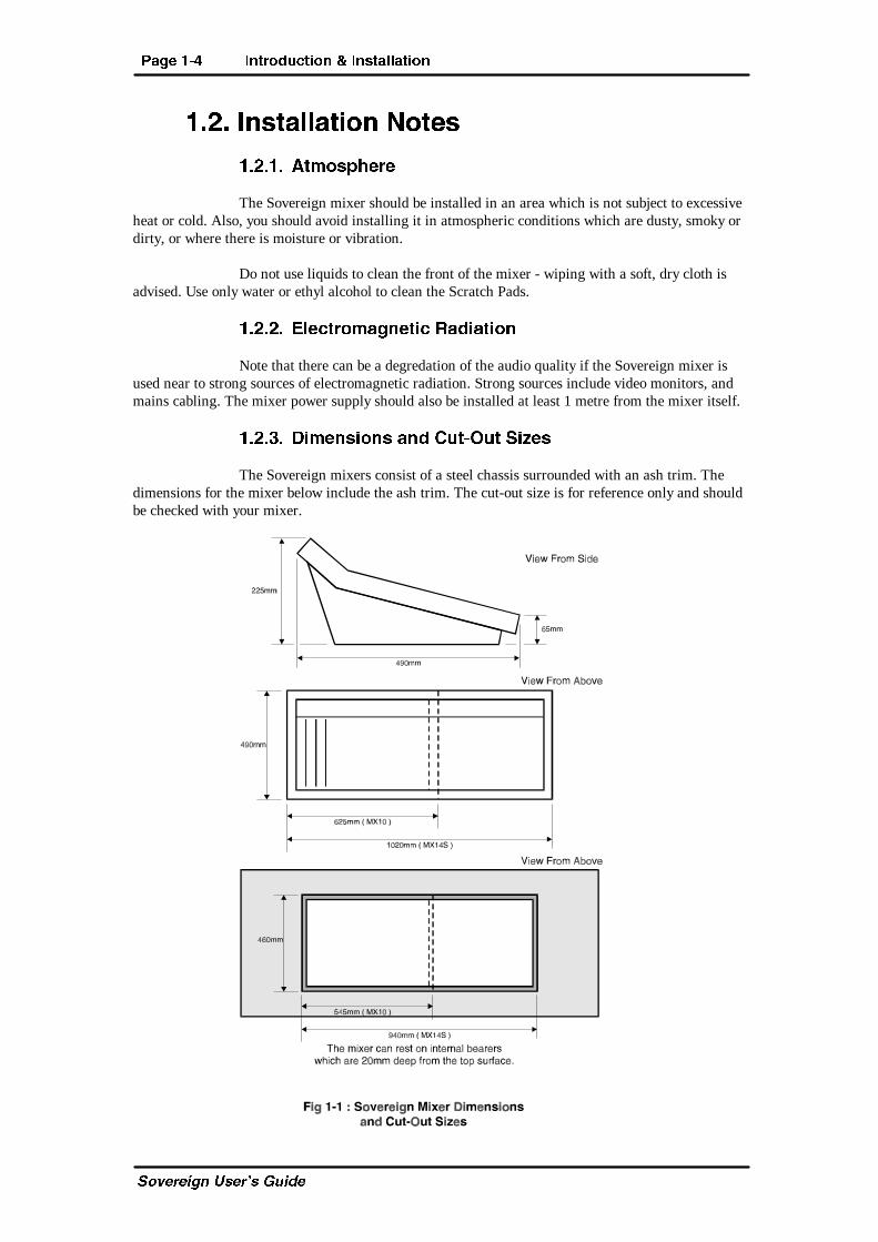
�!�"� 3X\T]bX^]b P]S 2dc�>dc BXiTb
The Sovereign mixers consist of a steel chassis surrounded with an ash trim. Thedimensions for the mixer below include the ash trim. The cut-out size is for reference only and shouldbe checked with your mixer.
8]ca^SdRcX^] � 8]bcP[[PcX^] ?PVT �$
C_fUbUYW^ EcUb�c 7eYTU
�!�#� <^Sd[T 2^]UXVdaPcX^]
Each of the modules is configured by jumper settings which are displayed in the“Module Options and Jumper Settings” section of each Chapter. You should ensure that you arethoroughly familiar with the settings available for each module before attempting installation of themixer. This is because some options, such as Talk-back, may involve configuring a number ofdifferent modules, including the Master Output and Monitor Module.
?PVT �% 8]ca^SdRcX^] � 8]bcP[[PcX^]
C_fUbUYW^ EcUb�c 7eYTU
�"� 2^]]TRc^ab P]S 2PQ[X]V
Many of the problems associated with installing and maintaining a mixing consoleare due to the use of poor cables or faulty connections. It is recommended that, whereever possible,pre-wired cables are purchased from recommended manufacturers. If you need bespoke cablesmaking, please ensure that the work is carried out by a qualified engineer.
The main types of connectors used with the Sovereign mixers are the following :
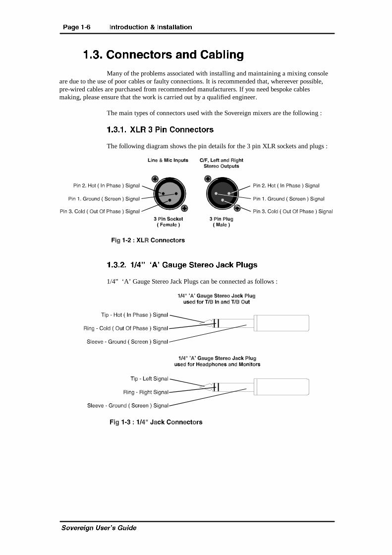
�"� � G;A " ?X] 2^]]TRc^ab
The following diagram shows the pin details for the 3 pin XLR sockets and plugs :
�"�!� �#² ³0´ 6PdVT BcTaT^ 9PRZ ?[dVb
1/4” ‘A’ Gauge Stereo Jack Plugs can be connected as follows :
8]ca^SdRcX^] � 8]bcP[[PcX^] ?PVT �&
C_fUbUYW^ EcUb�c 7eYTU
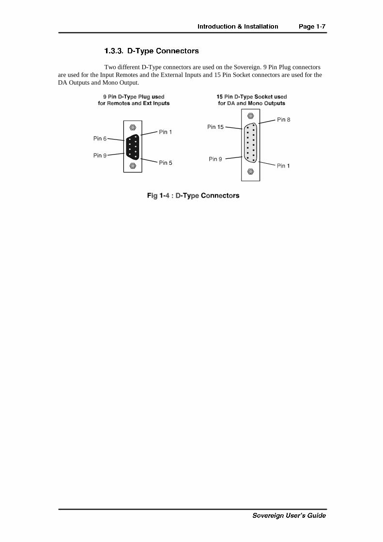
�"�"� 3�Ch_T 2^]]TRc^ab
Two different D-Type connectors are used on the Sovereign. 9 Pin Plug connectorsare used for the Input Remotes and the External Inputs and 15 Pin Socket connectors are used for theDA Outputs and Mono Output.
?PVT �' 8]ca^SdRcX^] � 8]bcP[[PcX^]
C_fUbUYW^ EcUb�c 7eYTU
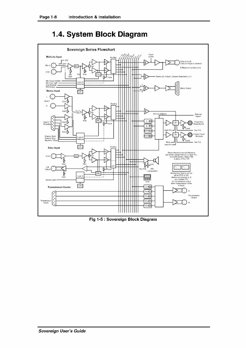
�#� BhbcT\ 1[^RZ 3XPVaP\
5XV �$ ) B^eTaTXV] 1[^RZ 3XPVaP\
<XR�;X]T <^Sd[T ?PVT !�
C_fUbUYW^ EcUb�c 7eYTU
!� <XR�;X]T�8]_dc�<^Sd[T
!� � ?P]T[ 2^]ca^[b
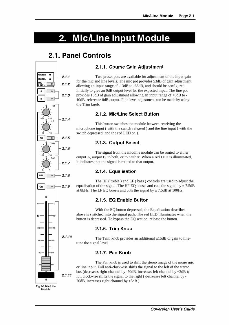
!� � � 2^dabT 6PX] 0SYdbc\T]c
Two preset pots are available for adjustment of the input gainfor the mic and line levels. The mic pot provides 53dB of gain adjustmentallowing an input range of -13dB to -66dB, and should be configuredinitially to give an 0dB output level for the expected input. The line potprovides 16dB of gain adjustment allowing an input range of +6dB to -10dB, reference 0dB output. Fine level adjustment can be made by usingthe Trim knob.
!� �!� <XR�;X]T BT[TRc 1dcc^]
This button switches the module between receiving themicrophone input ( with the switch released ) and the line input ( with theswitch depressed, and the red LED on ).
!� �"� >dc_dc BT[TRc
The signal from the mic/line module can be routed to eitheroutput A, output B, to both, or to neither. When a red LED is illuminated,it indicates that the signal is routed to that output.
!� �#� 4`dP[XbPcX^]
The HF ( treble ) and LF ( bass ) controls are used to adjust theequalisation of the signal. The HF EQ boosts and cuts the signal by ± 7.5dBat 8kHz. The LF EQ boosts and cuts the signal by ± 7.5dB at 100Hz.
!� �$� 4@ 4]PQ[T 1dcc^]
With the EQ button depressed, the Equalisation describedabove is switched into the signal path. The red LED illuminates when thebutton is depressed. To bypass the EQ section, release the button.
!� �%� CaX\ :]^Q
The Trim knob provides an additional ±15dB of gain to fine-tune the signal level.
!� �&� ?P] :]^Q
The Pan knob is used to shift the stereo image of the mono micor line input. Full anti-clockwise shifts the signal to the left of the stereobus (decreases right channel by -70dB, increases left channel by +3dB );full clockwise shifts the signal to the right ( decreases left channel by -70dB, increases right channel by +3dB )
?PVT !�! <XR�;X]T <^Sd[T
C_fUbUYW^ EcUb�c 7eYTU
!� �'� ?aT�5PST ;XbcT] � ?5; � 1dcc^]
With the PFL button depressed, the incoming signal on this channel is routed to the PFLbus so that it can be heard in the Monitors section ( by selecting Auto-PFL ). The PFL only operateswhen the fader is fully down, unless jumper J11 is not fitted when the PFL will operate with the fadereither up or down. PFL is active when the Yellow LED is illuminated in the button.
!� �(� >] 1dcc^]
The On button can be used to start and stop ( selectable by jumper settings ) aremote piece of equipment, as well as working in conjunction with the fader open signal to allowoutput from the channel. For the fader to operate, the On button must be illuminated. The Green LEDin the button glows at two brightnesses. If the fader is down when the On button is pushed, the LEDglows at half brightness and the circuitry can be regarded as being armed. To activate the circuitry,the fader should be moved away from the down position - the LED then glows with full power.
If the On button is pushed while the fader is already away from the down position,the circuitry will be enabled as soon as the button is pushed.
!� � �� 5PSTa
The 100mm long throw ALPS VCA fader provides a unity gain ( 0dB ) when fullyopen. The scale shows the attenuation. The fader open signal is produced by a voltage detecting op-amp and is disabled when the fader is in the fully down position. The fader open signal is used for thefader start/timer functions. The channel input is routed to the outputs whenever the fader is open andthe On switch and output switch are selected, provided that the Cough remote is not being used.
!� � � BRaPcRW ?PS
A white pad is provided at the bottom of the module on to which you can write thefunction of the channel, for example, “Presenter’s Mic”.
<XR�;X]T <^Sd[T ?PVT !�"
C_fUbUYW^ EcUb�c 7eYTU
!�!� ATPa ?P]T[
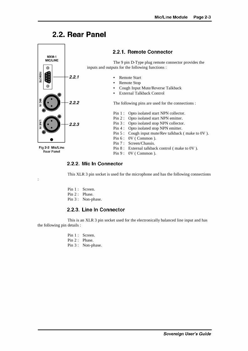
!�!� � AT\^cT 2^]]TRc^a
The 9 pin D-Type plug remote connector provides theinputs and outputs for the following functions :
• Remote Start• Remote Stop• Cough Input Mute/Reverse Talkback• External Talkback Control
The following pins are used for the connections :
Pin 1 : Opto isolated start NPN collector.Pin 2 : Opto isolated start NPN emitter.Pin 3 : Opto isolated stop NPN collector.Pin 4 : Opto isolated stop NPN emitter.Pin 5 : Cough input mute/Rev talkback ( make to 0V ).Pin 6 : 0V ( Common ).Pin 7 : Screen/Chassis.Pin 8 : External talkback control ( make to 0V ).Pin 9 : 0V ( Common ).
!�!�!� <XR 8] 2^]]TRc^a
This XLR 3 pin socket is used for the microphone and has the following connections:
Pin 1 : Screen.Pin 2 : Phase.Pin 3 : Non-phase.
!�!�"� ;X]T 8] 2^]]TRc^a
This is an XLR 3 pin socket used for the electronically balanced line input and hasthe following pin details :
Pin 1 : Screen.Pin 2 : Phase.Pin 3 : Non-phase.
?PVT !�# <XR�;X]T <^Sd[T
C_fUbUYW^ EcUb�c 7eYTU
!�"� <^Sd[T >_cX^]b P]S 9d\_Ta BTccX]Vb
The mic/line module can be configured in a number of different ways depending onthe jumper options set on the board. The options available are :
• Using a phantom powered microphone.• Enable full LF Response on microphone input.• Select remote start/stop for microphone or line.• Enable continuous momentary start from channel On button.• Select momentary or latched start.• Select to stop on fader down, or stop on fader down or on button off.• Select monitor mute for studio or control room.• Set channel to start the timer automatically.• Enable/disable the remote stop.• Enable or disable the auto pre-fade listen fader cancel.
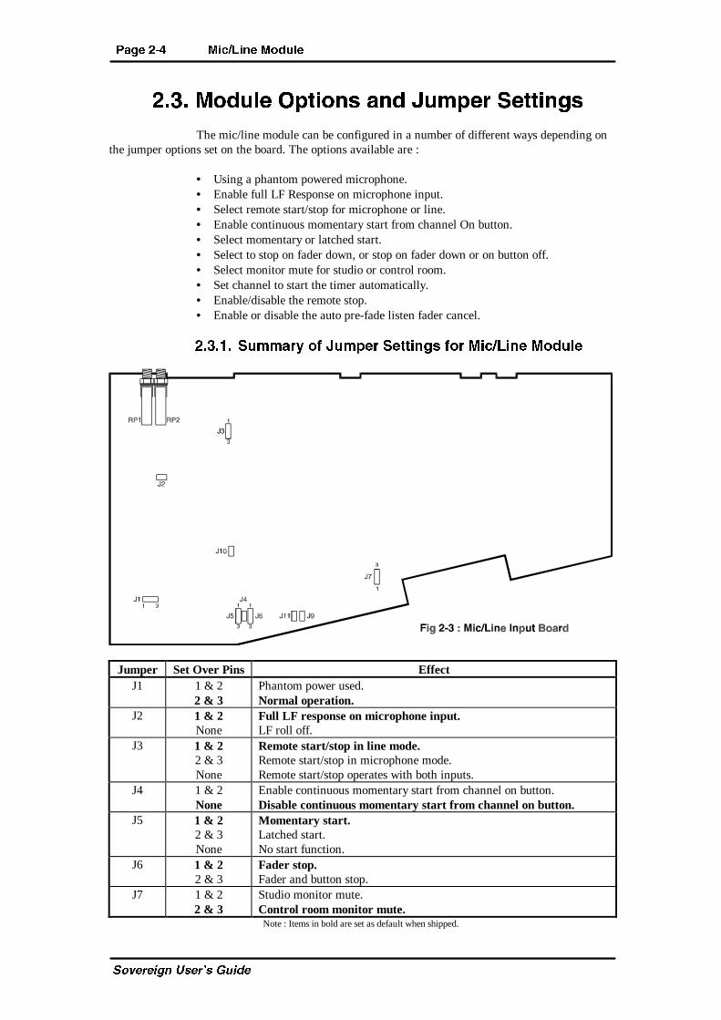
!�"� � Bd\\Pah ^U 9d\_Ta BTccX]Vb U^a <XR�;X]T <^Sd[T
Jumper Set Over Pins EffectJ1 1 & 2
2 & 3Phantom power used.Normal operation.
J2 1 & 2None
Full LF response on microphone input.LF roll off.
J3 1 & 22 & 3None
Remote start/stop in line mode.Remote start/stop in microphone mode.Remote start/stop operates with both inputs.
J4 1 & 2None
Enable continuous momentary start from channel on button.Disable continuous momentary start from channel on button.
J5 1 & 22 & 3None
Momentary start.Latched start.No start function.
J6 1 & 22 & 3
Fader stop.Fader and button stop.
J7 1 & 22 & 3
Studio monitor mute.Control room monitor mute.Note : Items in bold are set as default when shipped.
<XR�;X]T <^Sd[T ?PVT !�$
C_fUbUYW^ EcUb�c 7eYTU
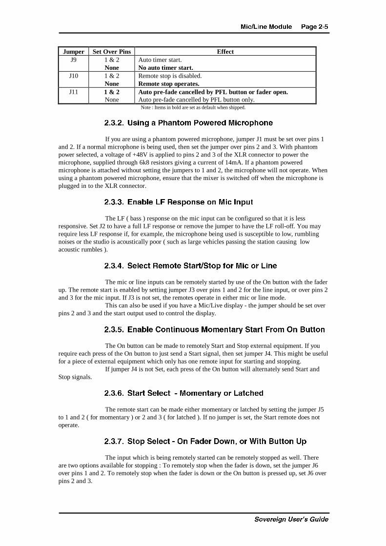
Jumper Set Over Pins EffectJ9 1 & 2
NoneAuto timer start.No auto timer start.
J10 1 & 2None
Remote stop is disabled.Remote stop operates.
J11 1 & 2None
Auto pre-fade cancelled by PFL button or fader open.Auto pre-fade cancelled by PFL button only.Note : Items in bold are set as default when shipped.
!�"�!� DbX]V P ?WP]c^\ ?^fTaTS <XRa^_W^]T
If you are using a phantom powered microphone, jumper J1 must be set over pins 1and 2. If a normal microphone is being used, then set the jumper over pins 2 and 3. With phantompower selected, a voltage of +48V is applied to pins 2 and 3 of the XLR connector to power themicrophone, supplied through 6k8 resistors giving a current of 14mA. If a phantom poweredmicrophone is attached without setting the jumpers to 1 and 2, the microphone will not operate. Whenusing a phantom powered microphone, ensure that the mixer is switched off when the microphone isplugged in to the XLR connector.
!�"�"� 4]PQ[T ;5 ATb_^]bT ^] <XR 8]_dc
The LF ( bass ) response on the mic input can be configured so that it is lessresponsive. Set J2 to have a full LF response or remove the jumper to have the LF roll-off. You mayrequire less LF response if, for example, the microphone being used is susceptible to low, rumblingnoises or the studio is acoustically poor ( such as large vehicles passing the station causing lowacoustic rumbles ).
!�"�#� BT[TRc AT\^cT BcPac�Bc^_ U^a <XR ^a ;X]T
The mic or line inputs can be remotely started by use of the On button with the faderup. The remote start is enabled by setting jumper J3 over pins 1 and 2 for the line input, or over pins 2and 3 for the mic input. If J3 is not set, the remotes operate in either mic or line mode.
This can also be used if you have a Mic/Live display - the jumper should be set overpins 2 and 3 and the start output used to control the display.
!�"�$� 4]PQ[T 2^]cX]d^db <^\T]cPah BcPac 5a^\ >] 1dcc^]
The On button can be made to remotely Start and Stop external equipment. If yourequire each press of the On button to just send a Start signal, then set jumper J4. This might be usefulfor a piece of external equipment which only has one remote input for starting and stopping.
If jumper J4 is not Set, each press of the On button will alternately send Start andStop signals.
!�"�%� BcPac BT[TRc � <^\T]cPah ^a ;PcRWTS
The remote start can be made either momentary or latched by setting the jumper J5to 1 and 2 ( for momentary ) or 2 and 3 ( for latched ). If no jumper is set, the Start remote does notoperate.
!�"�&� Bc^_ BT[TRc � >] 5PSTa 3^f]� ^a FXcW 1dcc^] D_
The input which is being remotely started can be remotely stopped as well. Thereare two options available for stopping : To remotely stop when the fader is down, set the jumper J6over pins 1 and 2. To remotely stop when the fader is down or the On button is pressed up, set J6 overpins 2 and 3.
?PVT !�% <XR�;X]T <^Sd[T
C_fUbUYW^ EcUb�c 7eYTU
!�"�'� <^]Xc^a <dcT BT[TRc � BcdSX^ ^a 2^]ca^[ A^^\
This option is for use with the mic input. When a microphone is live to air, themonitor speakers in the room containing the microphone will need to be muted so that there is nofeedback. So, for example, if the mic input is being used for a microphone in the studio, the studiomonitors should be muted. Setting J7 over pins 1 and 2 will mute the studio monitors when the faderis up, setting J7 over pins 2 and 3 will mute the control room monitors.
!�"�(� BTc c^ BcPac cWT CX\Ta 0dc^\PcXRP[[h
Each of the channels can be configured so that the timer on the meter bridge iscontrolled by the use of the fader. This may be useful for timing the duration of music tracks orpresenter speech. Set jumper J9 to control the timer with the module fader being configured. Removejumper J9 to disable timer control.
When controlled by a channel fader, the timer operates in the following way. Whenthe fader is opened, if the timer is not already running, it will reset the counter and start the timer. Ifthe timer is already running when the fader is opened, the counter begins counting but freezes for 3seconds, so that you can view and note the “start” time. After three seconds the counter will jump toshow the increasing time and will then continue.
The timer will be stopped by a manual stop. The timer can only be reset when in theStop mode.
!�"� �� 3XbPQ[T cWT AT\^cT Bc^_ 5d]RcX^]
The remote Stop function can be disabled by setting J10. Leaving the jumper offenables the remote Stop function.
!�"� � 4]PQ[T cWT 0dc^\PcXR ?aT�UPST ;XbcT] 5PSTa 2P]RT[
The PFL function can be cancelled by the fader opening or by using the PFL buttonif jumper J11 is set. When J11 is off, the PFL function is not cancelled by the fader open signal.
<XR�;X]T <^Sd[T ?PVT !�&
C_fUbUYW^ EcUb�c 7eYTU
!�#� 0__[XRPcX^]bThis section of the handbook provides examples of how to configure the module for
typical applications :
!�#� � 2^]ca^[[X]V P <XR�;XeT 3Xb_[Ph
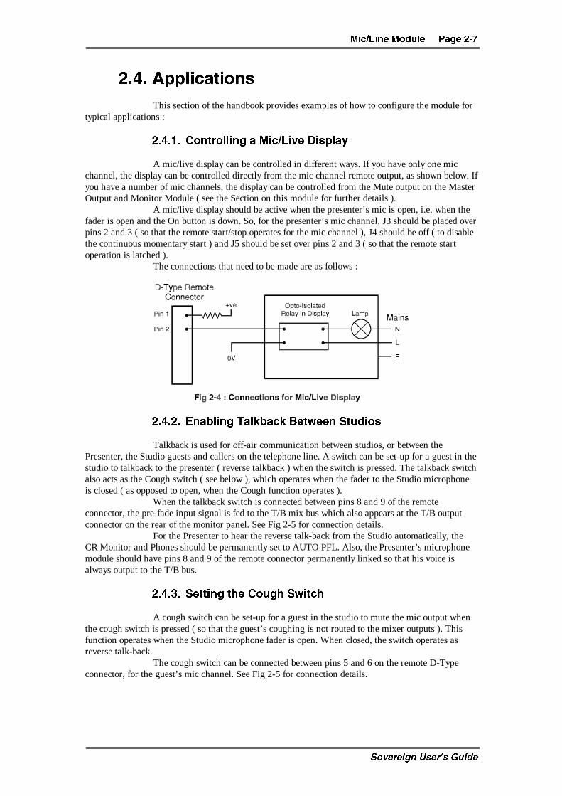
A mic/live display can be controlled in different ways. If you have only one micchannel, the display can be controlled directly from the mic channel remote output, as shown below. Ifyou have a number of mic channels, the display can be controlled from the Mute output on the MasterOutput and Monitor Module ( see the Section on this module for further details ).
A mic/live display should be active when the presenter’s mic is open, i.e. when thefader is open and the On button is down. So, for the presenter’s mic channel, J3 should be placed overpins 2 and 3 ( so that the remote start/stop operates for the mic channel ), J4 should be off ( to disablethe continuous momentary start ) and J5 should be set over pins 2 and 3 ( so that the remote startoperation is latched ).
The connections that need to be made are as follows :
!�#�!� 4]PQ[X]V CP[ZQPRZ 1TcfTT] BcdSX^b
Talkback is used for off-air communication between studios, or between thePresenter, the Studio guests and callers on the telephone line. A switch can be set-up for a guest in thestudio to talkback to the presenter ( reverse talkback ) when the switch is pressed. The talkback switchalso acts as the Cough switch ( see below ), which operates when the fader to the Studio microphoneis closed ( as opposed to open, when the Cough function operates ).
When the talkback switch is connected between pins 8 and 9 of the remoteconnector, the pre-fade input signal is fed to the T/B mix bus which also appears at the T/B outputconnector on the rear of the monitor panel. See Fig 2-5 for connection details.
For the Presenter to hear the reverse talk-back from the Studio automatically, theCR Monitor and Phones should be permanently set to AUTO PFL. Also, the Presenter’s microphonemodule should have pins 8 and 9 of the remote connector permanently linked so that his voice isalways output to the T/B bus.
!�#�"� BTccX]V cWT 2^dVW BfXcRW
A cough switch can be set-up for a guest in the studio to mute the mic output whenthe cough switch is pressed ( so that the guest’s coughing is not routed to the mixer outputs ). Thisfunction operates when the Studio microphone fader is open. When closed, the switch operates asreverse talk-back.
The cough switch can be connected between pins 5 and 6 on the remote D-Typeconnector, for the guest’s mic channel. See Fig 2-5 for connection details.
?PVT !�' <XR�;X]T <^Sd[T
C_fUbUYW^ EcUb�c 7eYTU
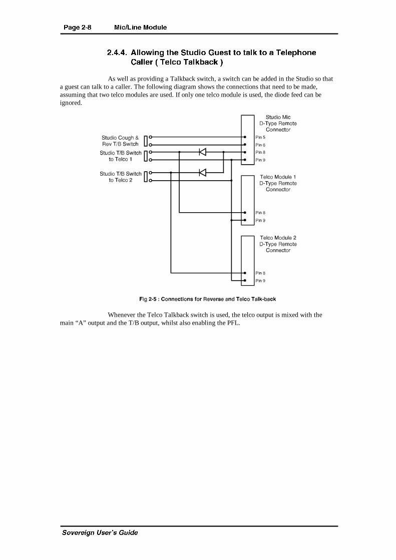
!�#�#� 0[[^fX]V cWT BcdSX^ 6dTbc c^ cP[Z c^ P CT[T_W^]T
2P[[Ta � CT[R^ CP[ZQPRZ �
As well as providing a Talkback switch, a switch can be added in the Studio so thata guest can talk to a caller. The following diagram shows the connections that need to be made,assuming that two telco modules are used. If only one telco module is used, the diode feed can beignored.
Whenever the Telco Talkback switch is used, the telco output is mixed with themain “A” output and the T/B output, whilst also enabling the PFL.
3dP[ BcTaT^ ;X]T 8]_dc <^Sd[T ?PVT "�
C_fUbUYW^ EcUb�c 7eYTU
"� 3dP[�BcTaT^�;X]T�8]_dc�<^Sd[T
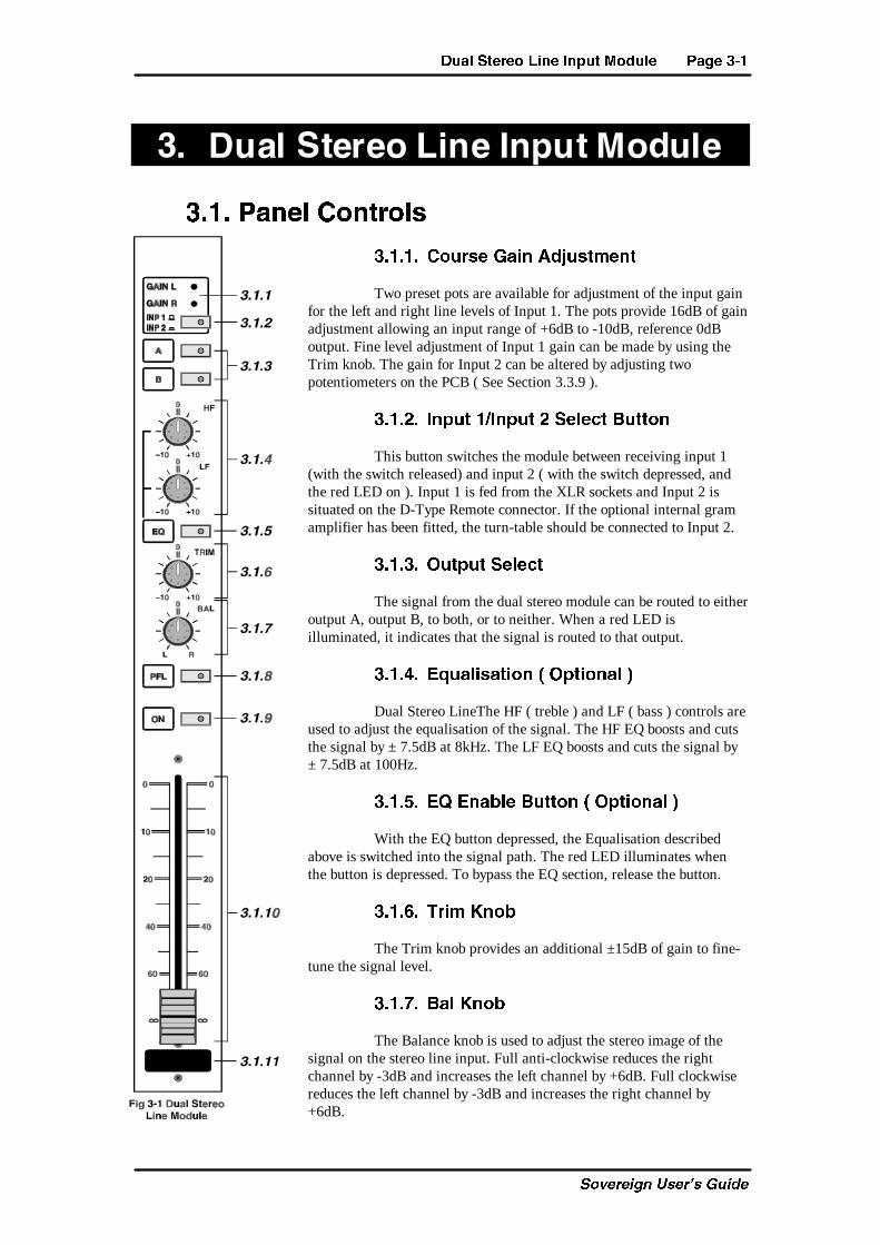
"� � ?P]T[ 2^]ca^[b
"� � � 2^dabT 6PX] 0SYdbc\T]c
Two preset pots are available for adjustment of the input gainfor the left and right line levels of Input 1. The pots provide 16dB of gainadjustment allowing an input range of +6dB to -10dB, reference 0dBoutput. Fine level adjustment of Input 1 gain can be made by using theTrim knob. The gain for Input 2 can be altered by adjusting twopotentiometers on the PCB ( See Section 3.3.9 ).
"� �!� 8]_dc �8]_dc ! BT[TRc 1dcc^]
This button switches the module between receiving input 1(with the switch released) and input 2 ( with the switch depressed, andthe red LED on ). Input 1 is fed from the XLR sockets and Input 2 issituated on the D-Type Remote connector. If the optional internal gramamplifier has been fitted, the turn-table should be connected to Input 2.
"� �"� >dc_dc BT[TRc
The signal from the dual stereo module can be routed to eitheroutput A, output B, to both, or to neither. When a red LED isilluminated, it indicates that the signal is routed to that output.
"� �#� 4`dP[XbPcX^] � >_cX^]P[ �
Dual Stereo LineThe HF ( treble ) and LF ( bass ) controls areused to adjust the equalisation of the signal. The HF EQ boosts and cutsthe signal by ± 7.5dB at 8kHz. The LF EQ boosts and cuts the signal by± 7.5dB at 100Hz.
"� �$� 4@ 4]PQ[T 1dcc^] � >_cX^]P[ �
With the EQ button depressed, the Equalisation describedabove is switched into the signal path. The red LED illuminates whenthe button is depressed. To bypass the EQ section, release the button.
"� �%� CaX\ :]^Q
The Trim knob provides an additional ±15dB of gain to fine-tune the signal level.
"� �&� 1P[ :]^Q
The Balance knob is used to adjust the stereo image of thesignal on the stereo line input. Full anti-clockwise reduces the rightchannel by -3dB and increases the left channel by +6dB. Full clockwisereduces the left channel by -3dB and increases the right channel by+6dB.
?PVT "�! 3dP[ BcTaT^ ;X]T 8]_dc <^Sd[T
C_fUbUYW^ EcUb�c 7eYTU
"� �'� ?aT�5PST ;XbcT] � ?5; � 1dcc^]
With the PFL button depressed, the incoming signal on this channel is routed to the PFLbus so that it can be heard in the Monitors section ( by selecting Auto-PFL ). The PFL only operateswhen the fader is fully down, unless jumper J11 is not fitted when the PFL will operate with thefader either up or down. PFL is active when the Yellow LED is illuminated in the button.
"� �(� >] 1dcc^]
The On button can be used to start and stop ( selectable by jumper settings ) aremote piece of equipment, as well as working in conjunction with the fader open signal to allowoutput from the channel. For the fader to operate, the On button must be illuminated. The Green LEDin the button glows at two brightnesses. If the fader is down when the On button is pushed, the LEDglows at half brightness and the circuitry can be regarded as being armed. To activate the circuitry,the fader should be moved away from the down position - the LED then glows with full power.
If the On button is pushed while the fader is already away from the down position,the remote circuitry will be enabled as soon as the button is pushed.
"� � �� 5PSTa
The 100mm long throw ALPS VCA fader provides a unity gain ( 0dB ) when fullyopen. The scale shows the attenuation. The fader open signal is produced by a voltage detecting op-amp and is disabled when the fader is in the fully down position. The fader open signal is used for thefader starttimer functions. The channel input is routed to the outputs whenever the fader is open andthe On switch and output switch are selected.
"� � � BRaPcRW ?PS
A white pad is provided at the bottom of the module on to which you can write thefunction of the channel, for example, “CD 1”.
3dP[ BcTaT^ ;X]T 8]_dc <^Sd[T ?PVT "�"
C_fUbUYW^ EcUb�c 7eYTU
"�!� ATPa ?P]T[
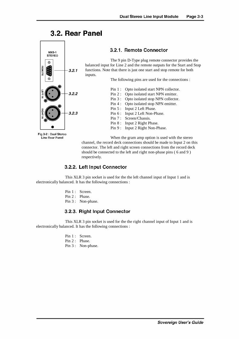
"�!� � AT\^cT 2^]]TRc^a
The 9 pin D-Type plug remote connector provides thebalanced input for Line 2 and the remote outputs for the Start and Stopfunctions. Note that there is just one start and stop remote for bothinputs.
The following pins are used for the connections :
Pin 1 : Opto isolated start NPN collector.Pin 2 : Opto isolated start NPN emitter.Pin 3 : Opto isolated stop NPN collector.Pin 4 : Opto isolated stop NPN emitter.Pin 5 : Input 2 Left Phase.Pin 6 : Input 2 Left Non-Phase.Pin 7 : Screen/Chassis.Pin 8 : Input 2 Right Phase.Pin 9 : Input 2 Right Non-Phase.
When the gram amp option is used with the stereochannel, the record deck connections should be made to Input 2 on thisconnector. The left and right screen connections from the record deckshould be connected to the left and right non-phase pins ( 6 and 9 )respectively.
"�!�!� ;TUc 8]_dc 2^]]TRc^a
This XLR 3 pin socket is used for the the left channel input of Input 1 and iselectronically balanced. It has the following connections :
Pin 1 : Screen.Pin 2 : Phase.Pin 3 : Non-phase.
"�!�"� AXVWc 8]_dc 2^]]TRc^a
This XLR 3 pin socket is used for the the right channel input of Input 1 and iselectronically balanced. It has the following connections :
Pin 1 : Screen.Pin 2 : Phase.Pin 3 : Non-phase.
?PVT "�# 3dP[ BcTaT^ ;X]T 8]_dc <^Sd[T
C_fUbUYW^ EcUb�c 7eYTU
"�"� <^Sd[T >_cX^]b P]S 9d\_Ta BTccX]Vb
The dual stereo line module can be configured in a number of different waysdepending on the jumper options set on the board. The options available are :
• Select remote start/stop for line input 1 or line input 2.• Enable continuous momentary start from channel On button.• Select momentary or latched start.• Set channel to start the timer automatically.• Enable/disable the remote stop.• Enable or disable the auto pre-fade listen fader cancel.
The gain of Input 2 can be defined by adjusting two potentiometers on the PCB. Anoption is available for fitting the module with an internal gram amplifier, so that a turntable can beconnected directly to the dual stereo input.
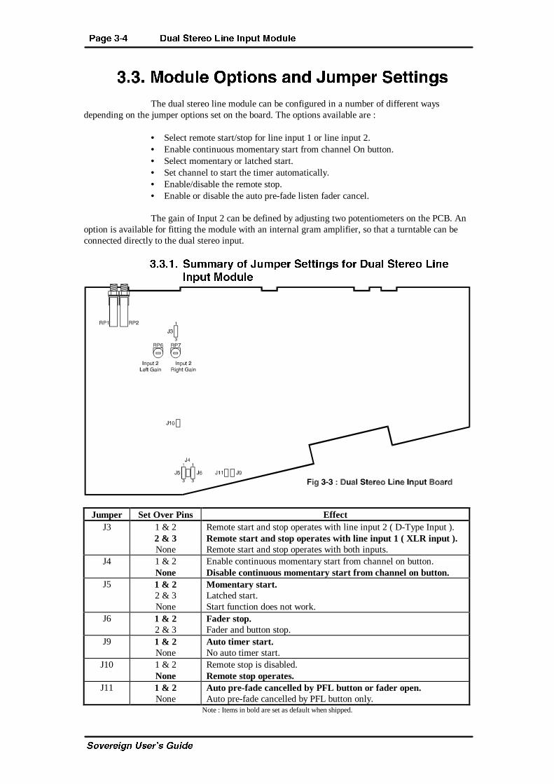
"�"� � Bd\\Pah ^U 9d\_Ta BTccX]Vb U^a 3dP[ BcTaT^ ;X]T
8]_dc <^Sd[T
Jumper Set Over Pins EffectJ3 1 & 2
2 & 3None
Remote start and stop operates with line input 2 ( D-Type Input ).Remote start and stop operates with line input 1 ( XLR input ).Remote start and stop operates with both inputs.
J4 1 & 2None
Enable continuous momentary start from channel on button.Disable continuous momentary start from channel on button.
J5 1 & 22 & 3None
Momentary start.Latched start.Start function does not work.
J6 1 & 22 & 3
Fader stop.Fader and button stop.
J9 1 & 2None
Auto timer start.No auto timer start.
J10 1 & 2None
Remote stop is disabled.Remote stop operates.
J11 1 & 2None
Auto pre-fade cancelled by PFL button or fader open.Auto pre-fade cancelled by PFL button only.
Note : Items in bold are set as default when shipped.
3dP[ BcTaT^ ;X]T 8]_dc <^Sd[T ?PVT "�$
C_fUbUYW^ EcUb�c 7eYTU
"�"�!� BT[TRc AT\^cT BcPac�Bc^_ U^a ;X]T 8]_dc ^a !
There is just one set of remote start and stop connections for both Line Inputs 1 and2. Jumper J3 selects which input is connected to the piece of equipment that needs to be controlledremotely. With J3 set over pins 1 and 2, the remotes will only operate when Input 2 is selected. WithJ3 set over pins 2 and 3, the remotes will only operate when Input 1 is selected.
If J3 is not set, the remote start and stop will operate whether Input 1 or Input 2 areselected.
"�"�"� 4]PQ[T 2^]cX]d^db <^\T]cPah BcPac 5a^\ >] 1dcc^]
The On button can be made to remotely Start and Stop external equipment. If yourequire each press of the On button to just send a Start signal, then set jumper J4. This might be usefulfor a piece of external equipment which only has one remote input for starting and stopping.
If jumper J4 is not Set, each press of the On button will alternately send Start andStop signals.
"�"�#� BcPac BT[TRc � <^\T]cPah ^a ;PcRWTS
The remote start can be made either momentary or latched by setting the jumper J5to 1 and 2 ( for momentary ) or 2 and 3 ( for latched ). If no jumper is set, the Start remote does notoperate.
"�"�$� Bc^_ BT[TRc � >] 5PSTa 3^f]� ^a FXcW 1dcc^] D_
The input which is being remotely started can be remotely stopped as well. Thereare two options available for stopping : To remotely stop when the fader is down, set the jumper J6over pins 1 and 2. To remotely stop when the fader is down or the On button is pressed up, set J6 overpins 2 and 3.
"�"�%� BTc c^ BcPac cWT CX\Ta 0dc^\PcXRP[[h
Each of the channels can be configured so that the timer on the meter bridge iscontrolled by the use of the fader. This may be useful for timing the duration of music tracks. Setjumper J9 to control the timer with the module fader being configured. Remove jumper J9 to disabletimer control.
When controlled by a channel fader, the timer operates in the following way. Whenthe fader is opened, if the timer is not already running, it will reset the counter and start the timer. Ifthe timer is already running when the fader is opened, the counter begins counting but freezes for 3seconds, so that you can view and note the “start” time. After three seconds the counter will jump toshow the increasing time and will then continue.
The timer will be stopped by a manual stop. The timer can only be reset when in theStop mode.
"�"�&� 3XbPQ[T cWT AT\^cT Bc^_ 5d]RcX^]
The remote Stop function can be disabled by setting J10. Leaving the jumper offenables the remote Stop function.
"�"�'� 2P]RT[ cWT 0dc^\PcXR ?aT�UPST ;XbcT]
The PFL function can be cancelled by the fader opening or by using the PFL buttonif jumper J11 is set. When Jll is off, the PFL function is not cancelled by the fader open signal.
?PVT "�% 3dP[ BcTaT^ ;X]T 8]_dc <^Sd[T
C_fUbUYW^ EcUb�c 7eYTU
"�"�(� 6PX] 0SYdbc\T]c U^a 8]_dc !
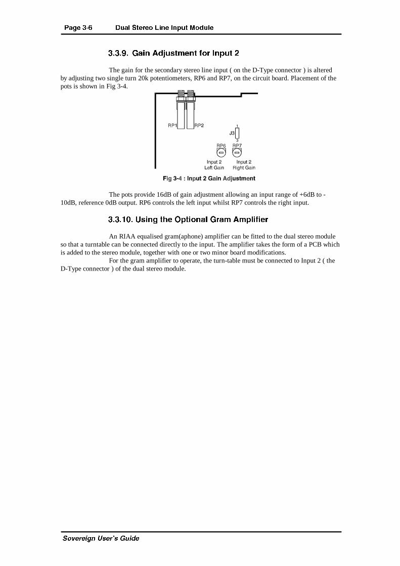
The gain for the secondary stereo line input ( on the D-Type connector ) is alteredby adjusting two single turn 20k potentiometers, RP6 and RP7, on the circuit board. Placement of thepots is shown in Fig 3-4.
The pots provide 16dB of gain adjustment allowing an input range of +6dB to -10dB, reference 0dB output. RP6 controls the left input whilst RP7 controls the right input.
"�"� �� DbX]V cWT >_cX^]P[ 6aP\ 0\_[XUXTa
An RIAA equalised gram(aphone) amplifier can be fitted to the dual stereo moduleso that a turntable can be connected directly to the input. The amplifier takes the form of a PCB whichis added to the stereo module, together with one or two minor board modifications.
For the gram amplifier to operate, the turn-table must be connected to Input 2 ( theD-Type connector ) of the dual stereo module.

CT[R^ <^Sd[T ?PVT #�
C_fUbUYW^ EcUb�c 7eYTU
#� CT[R^�<^Sd[T
#� � ?P]T[ 2^]ca^[b
#� � � 2^dabT 6PX] 0SYdbc\T]c
Two preset pots are available for adjustment of the input gainof the telco signal and the output gain of the cleanfeed. The C/F potprovides 10dB of gain adjustment allowing an output range of -6dB to+4dB, and should be configured initially to give an 0dB output level forthe expected input. The telco pot provides 16dB of gain adjustmentallowing an input range of +6dB to -10dB, reference 0dB output. Finelevel adjustment can be made by using the Trim knob.
#� �!� >dc_dc BT[TRc
The signal from the telco module can be routed to eitheroutput A, output B, to both, or to neither. When a red LED is illuminated,it indicates that the signal is routed to that output. It should be noted thatoutput A controls the cleanfeed signals and so should always bedesignated as the main programme output if telco channels are beingused.
#� �"� 4`dP[XbPcX^]
The HF ( treble ) and LF ( bass ) controls are used to adjustthe equalisation of the signal. The HF EQ boosts and cuts the signal by ±7.5dB at 8kHz. The LF EQ boosts and cuts the signal by ± 7.5dB at100Hz.
#� �#� 4@ 4]PQ[T 1dcc^]
With the EQ button depressed, the Equalisation describedabove is switched into the signal path. The red LED illuminates when thebutton is depressed. To bypass the EQ section, release the button.
#� �$� CaX\ :]^Q
The Trim knob provides an additional ±15dB of gain to fine-tune the signal level.
#� �%� ?P] :]^Q
The Pan knob is used to shift the stereo image of the lineinput. Full anti-clockwise shifts the signal to the left of the stereo bus(decreases right channel by -70dB, increases left channel by +3dB ); fullclockwise shifts the signal to the right ( decreases left channel by -70dB,increases right channel by +3dB ).
#� �&� ?aT�5PST ;XbcT] � ?5; � P]S CP[ZQPRZ
� C�1 � 1dcc^]
With the PFL button depressed, the incoming signal onthis channel is routed to the PFL bus so that it can be heard in the
?PVT #�! CT[R^ <^Sd[T
C_fUbUYW^ EcUb�c 7eYTU
Monitors section ( by selecting Auto-PFL ). The PFL only operates when the fader is fully down,unless jumper J11 is not fitted when the PFL will operate with the fader either up or down. PFL isactive when the Yellow LED is illuminated in the button.
The PFL button on the telco channel also switches the programme output and thetalkback bus to the cleanfeed output, so that the presenter can talk to the caller.
#� �'� 7^[S 1dcc^]
The Hold button is used as the Remote Divert for the telephone hybrid unit. It alsocontrols the cleanfeed audio output in conjunction with the output A select button ( but not B ). Whenboth the output A and the Hold button are On, audio is enabled at the cleanfeed output. If either theHold button or output A are not selected, the cleanfeed output is muted.
In operation, this means that the presenter can talk in PFL mode with the caller bypressing the Hold button. The presenter can then put the caller to air by pressing the A output button.
#� �(� 5PSTa
The 100mm long throw ALPS VCA fader provides a unity gain ( 0dB ) when fullyopen. The scale shows the attenuation. The fader open signal is produced by a voltage detecting op-amp and is disabled when the fader is in the fully down position. The fader open signal can be usedfor the fader start/timer functions. The channel input is routed to the outputs whenever the fader isopen and the output switch is selected.
#� � �� BRaPcRW ?PS
A white pad is provided at the bottom of the module on to which you can write thefunction of the channel, for example, “Presenter’s Mic”.
CT[R^ <^Sd[T ?PVT #�"
C_fUbUYW^ EcUb�c 7eYTU
#�!� ATPa ?P]T[
#�!� � AT\^cT 2^]]TRc^a
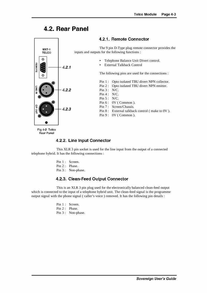
The 9 pin D-Type plug remote connector provides theinputs and outputs for the following functions :
• Telephone Balance Unit Divert control.• External Talkback Control
The following pins are used for the connections :
Pin 1 : Opto isolated TBU divert NPN collector.Pin 2 : Opto isolated TBU divert NPN emitter.Pin 3 : N/C.Pin 4 : N/C.Pin 5 : N/C.Pin 6 : 0V ( Common ).Pin 7 : Screen/Chassis.Pin 8 : External talkback control ( make to 0V ).Pin 9 : 0V ( Common ).
#�!�!� ;X]T 8]_dc 2^]]TRc^a
This XLR 3 pin socket is used for the line input from the output of a connectedtelephone hybrid. It has the following connections :
Pin 1 : Screen.Pin 2 : Phase.Pin 3 : Non-phase.
#�!�"� 2[TP]�5TTS >dc_dc 2^]]TRc^a
This is an XLR 3 pin plug used for the electronically balanced clean-feed outputwhich is connected to the input of a telephone hybrid unit. The clean-feed signal is the programmeoutput signal with the phone signal ( caller’s voice ) removed. It has the following pin details :
Pin 1 : Screen.Pin 2 : Phase.Pin 3 : Non-phase.
?PVT #�# CT[R^ <^Sd[T
C_fUbUYW^ EcUb�c 7eYTU
#�"� <^Sd[T >_cX^]b P]S 9d\_Ta BTccX]Vb
The telco module can be configured in a number of different ways depending on thejumper options set on the board. The options available are :
• Select momentary or latched TBU Divert.• Select which Clean-feed bus should be used.• Set channel to start and stop the timer automatically.• Enable or disable the auto pre-fade listen.
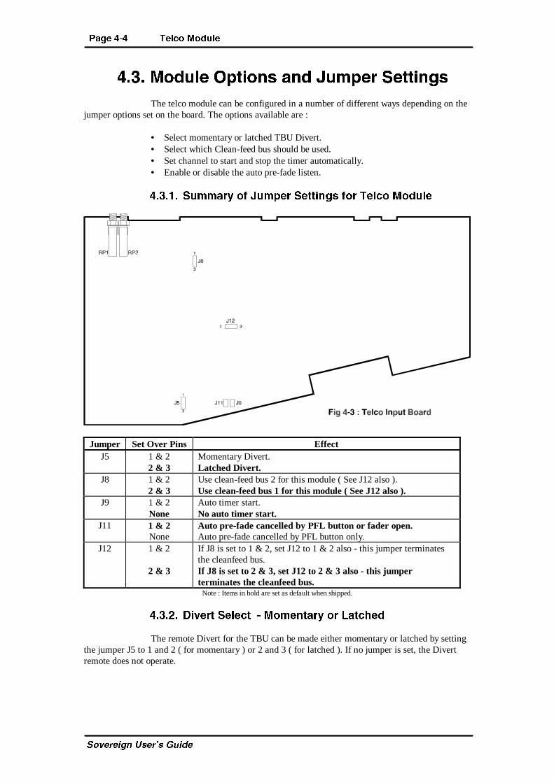
#�"� � Bd\\Pah ^U 9d\_Ta BTccX]Vb U^a CT[R^ <^Sd[T
Jumper Set Over Pins EffectJ5 1 & 2
2 & 3Momentary Divert.Latched Divert.
J8 1 & 22 & 3
Use clean-feed bus 2 for this module ( See J12 also ).Use clean-feed bus 1 for this module ( See J12 also ).
J9 1 & 2None
Auto timer start.No auto timer start.
J11 1 & 2None
Auto pre-fade cancelled by PFL button or fader open.Auto pre-fade cancelled by PFL button only.
J12 1 & 2
2 & 3
If J8 is set to 1 & 2, set J12 to 1 & 2 also - this jumper terminatesthe cleanfeed bus.If J8 is set to 2 & 3, set J12 to 2 & 3 also - this jumperterminates the cleanfeed bus.
Note : Items in bold are set as default when shipped.
#�"�!� 3XeTac BT[TRc � <^\T]cPah ^a ;PcRWTS
The remote Divert for the TBU can be made either momentary or latched by settingthe jumper J5 to 1 and 2 ( for momentary ) or 2 and 3 ( for latched ). If no jumper is set, the Divertremote does not operate.
CT[R^ <^Sd[T ?PVT #�$
C_fUbUYW^ EcUb�c 7eYTU
#�"�"� 2[TP]�5TTS 1db >dc_dc BT[TRc
The jumper J8 defines which Clean-Feed bus should be used inside the console forthe particular telco channel being configured. There can only be a maximum of two telco channels ineach mixer because there are only two clean-feed buses available.
If you have one telco module, set this jumper over pins 2 and 3 so that Clean-feedbus 1 is used. If you have two telco channels, set one module so that J8 is over pins 1 and 2 , and theother module so that it is over pins 2 and 3.
Jumper J12 should be configured in the same way as J8 to help prevent cross-talkbetween the two cleanfeed channels ( Note : Some mixers have not been fitted with this jumper. Theyhave had a hardware modification made to overcome any possible problems ).
#�"�#� BTc c^ BcPac cWT CX\Ta 0dc^\PcXRP[[h
Each of the channels can be configured so that the timer on the meter bridge iscontrolled by the use of the fader. This may be useful for timing the duration of a caller’sconversation. Set jumper J9 to control the timer with the module fader being configured. Removejumper J9 to disable timer control.
When controlled by a channel fader, the timer operates in the following way. Whenthe fader is opened, if the timer is not already running, it will reset the counter and start the timer. Ifthe timer is already running when the fader is opened, the counter begins counting but freezes for 3seconds, so that you can view and note the “start” time. After three seconds the counter will jump toshow the increasing time and will then continue.
The timer will be stopped by a manual stop. The timer can only be reset when in theStop mode.
#�"�$� 2P]RT[ cWT 0dc^\PcXR ?aT�UPST ;XbcT]
The PFL function can be cancelled by the fader opening or by using the PFL buttonif jumper J11 is set. When Jll is off, the PFL function is not cancelled by the fader open signal.
#�#� 0SSXcX^]P[ >_cX^]bWhenever a telco module is installed into a mixer, configuration settings in the
Master Output and Monitor Module have to be altered as well. These are to reduce cross-talk in thetelco module and involve the placement of two jumpers in each of the output boards. Please refer toSection 5.6.1.3 for further information.
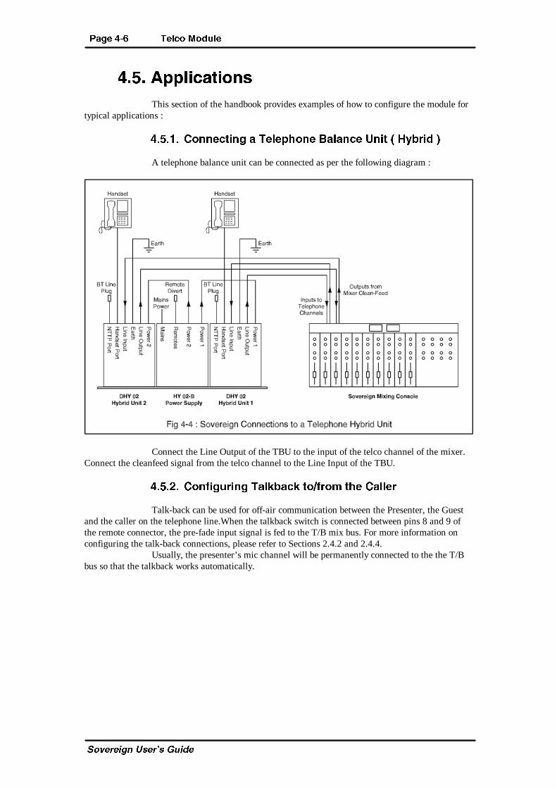
?PVT #�% CT[R^ <^Sd[T
C_fUbUYW^ EcUb�c 7eYTU
#�$� 0__[XRPcX^]bThis section of the handbook provides examples of how to configure the module for
typical applications :
#�$� � 2^]]TRcX]V P CT[T_W^]T 1P[P]RT D]Xc � 7hQaXS �
A telephone balance unit can be connected as per the following diagram :
Connect the Line Output of the TBU to the input of the telco channel of the mixer.Connect the cleanfeed signal from the telco channel to the Line Input of the TBU.
#�$�!� 2^]UXVdaX]V CP[ZQPRZ c^�Ua^\ cWT 2P[[Ta
Talk-back can be used for off-air communication between the Presenter, the Guestand the caller on the telephone line.When the talkback switch is connected between pins 8 and 9 ofthe remote connector, the pre-fade input signal is fed to the T/B mix bus. For more information onconfiguring the talk-back connections, please refer to Sections 2.4.2 and 2.4.4.
Usually, the presenter’s mic channel will be permanently connected to the the T/Bbus so that the talkback works automatically.
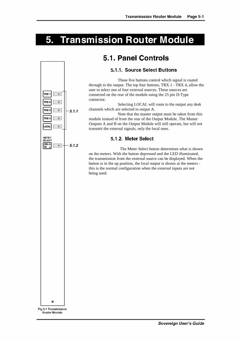
CaP]b\XbbX^] A^dcTa <^Sd[T ?PVT $�
C_fUbUYW^ EcUb�c 7eYTU
$� CaP]b\XbbX^]�A^dcTa�<^Sd[T
$� � ?P]T[ 2^]ca^[b
$� � � B^daRT BT[TRc 1dcc^]b
These five buttons control which signal is routedthrough to the output. The top four buttons, TRX 1 - TRX 4, allow theuser to select one of four external sources. These sources areconnected on the rear of the module using the 25 pin D-Typeconnector.
Selecting LOCAL will route to the output any deskchannels which are selected to output A.
Note that the master output must be taken from thismodule instead of from the rear of the Output Module. The MasterOutputs A and B on the Output Module will still operate, but will nottransmit the external signals, only the local ones.
$� �!� <TcTa BT[TRc
The Meter Select button determines what is shownon the meters. With the button depressed and the LED illuminated,the transmission from the external source can be displayed. When thebutton is in the up position, the local output is shown at the meters -this is the normal configuration when the external inputs are notbeing used.
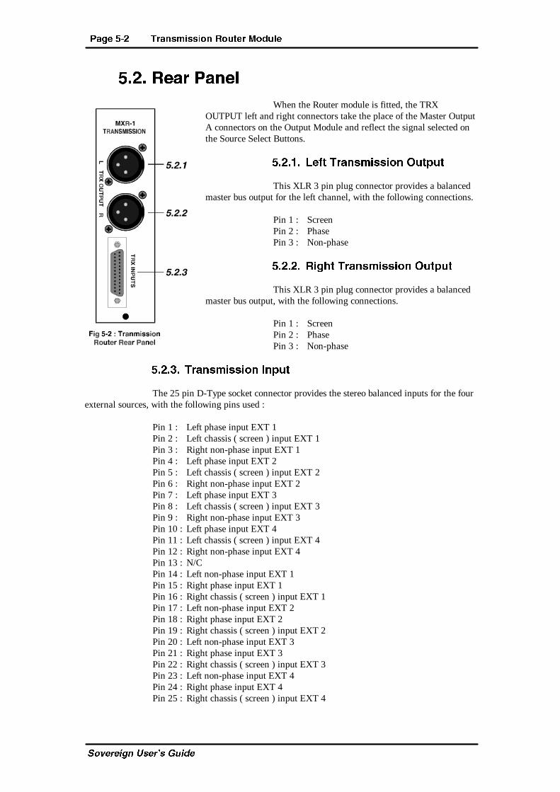
?PVT $�! CaP]b\XbbX^] A^dcTa <^Sd[T
C_fUbUYW^ EcUb�c 7eYTU
$�!� ATPa ?P]T[When the Router module is fitted, the TRX
OUTPUT left and right connectors take the place of the Master OutputA connectors on the Output Module and reflect the signal selected onthe Source Select Buttons.
$�!� � ;TUc CaP]b\XbbX^] >dc_dc
This XLR 3 pin plug connector provides a balancedmaster bus output for the left channel, with the following connections.
Pin 1 : ScreenPin 2 : PhasePin 3 : Non-phase
$�!�!� AXVWc CaP]b\XbbX^] >dc_dc
This XLR 3 pin plug connector provides a balancedmaster bus output, with the following connections.
Pin 1 : ScreenPin 2 : PhasePin 3 : Non-phase
$�!�"� CaP]b\XbbX^] 8]_dc
The 25 pin D-Type socket connector provides the stereo balanced inputs for the fourexternal sources, with the following pins used :
Pin 1 : Left phase input EXT 1Pin 2 : Left chassis ( screen ) input EXT 1Pin 3 : Right non-phase input EXT 1Pin 4 : Left phase input EXT 2Pin 5 : Left chassis ( screen ) input EXT 2Pin 6 : Right non-phase input EXT 2Pin 7 : Left phase input EXT 3Pin 8 : Left chassis ( screen ) input EXT 3Pin 9 : Right non-phase input EXT 3Pin 10 : Left phase input EXT 4Pin 11 : Left chassis ( screen ) input EXT 4Pin 12 : Right non-phase input EXT 4Pin 13 : N/CPin 14 : Left non-phase input EXT 1Pin 15 : Right phase input EXT 1Pin 16 : Right chassis ( screen ) input EXT 1Pin 17 : Left non-phase input EXT 2Pin 18 : Right phase input EXT 2Pin 19 : Right chassis ( screen ) input EXT 2Pin 20 : Left non-phase input EXT 3Pin 21 : Right phase input EXT 3Pin 22 : Right chassis ( screen ) input EXT 3Pin 23 : Left non-phase input EXT 4Pin 24 : Right phase input EXT 4Pin 25 : Right chassis ( screen ) input EXT 4
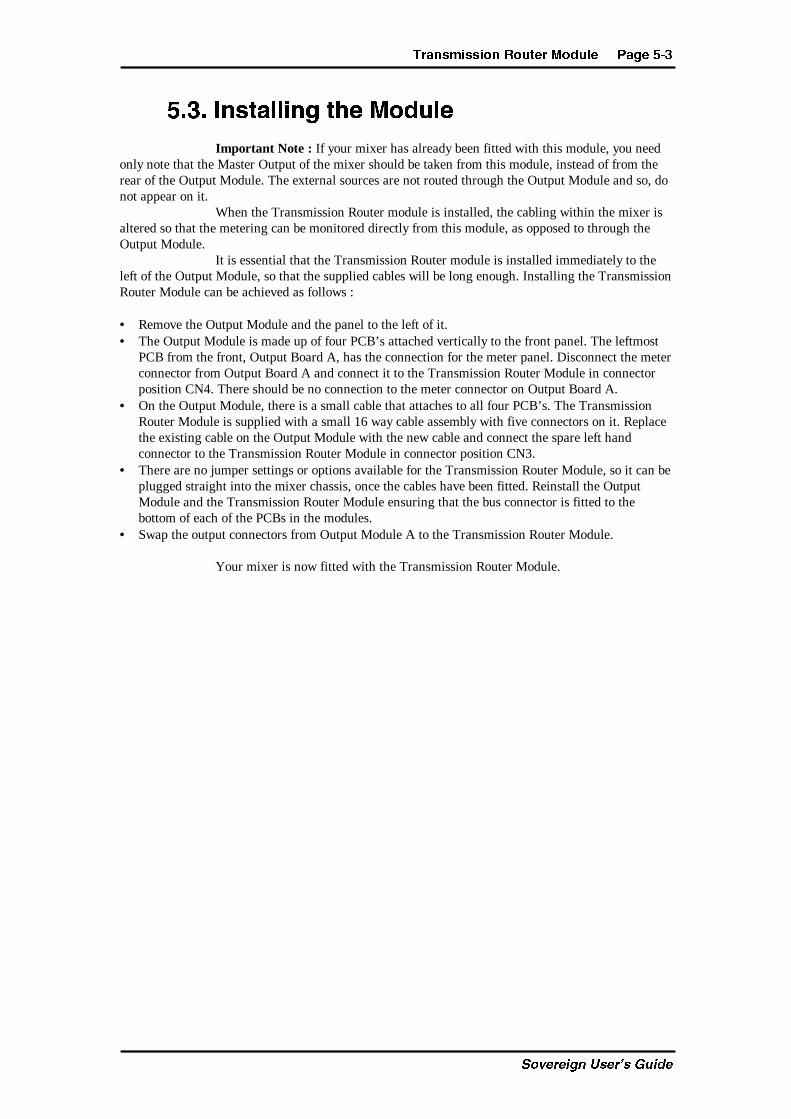
CaP]b\XbbX^] A^dcTa <^Sd[T ?PVT $�"
C_fUbUYW^ EcUb�c 7eYTU
$�"� 8]bcP[[X]V cWT <^Sd[T
Important Note : If your mixer has already been fitted with this module, you needonly note that the Master Output of the mixer should be taken from this module, instead of from therear of the Output Module. The external sources are not routed through the Output Module and so, donot appear on it.
When the Transmission Router module is installed, the cabling within the mixer isaltered so that the metering can be monitored directly from this module, as opposed to through theOutput Module.
It is essential that the Transmission Router module is installed immediately to theleft of the Output Module, so that the supplied cables will be long enough. Installing the TransmissionRouter Module can be achieved as follows :
• Remove the Output Module and the panel to the left of it.• The Output Module is made up of four PCB’s attached vertically to the front panel. The leftmost
PCB from the front, Output Board A, has the connection for the meter panel. Disconnect the meterconnector from Output Board A and connect it to the Transmission Router Module in connectorposition CN4. There should be no connection to the meter connector on Output Board A.
• On the Output Module, there is a small cable that attaches to all four PCB’s. The TransmissionRouter Module is supplied with a small 16 way cable assembly with five connectors on it. Replacethe existing cable on the Output Module with the new cable and connect the spare left handconnector to the Transmission Router Module in connector position CN3.
• There are no jumper settings or options available for the Transmission Router Module, so it can beplugged straight into the mixer chassis, once the cables have been fitted. Reinstall the OutputModule and the Transmission Router Module ensuring that the bus connector is fitted to thebottom of each of the PCBs in the modules.
• Swap the output connectors from Output Module A to the Transmission Router Module.
Your mixer is now fitted with the Transmission Router Module.
?PVT $�# CaP]b\XbbX^] A^dcTa <^Sd[T
C_fUbUYW^ EcUb�c 7eYTU
This page is deliberately blank.
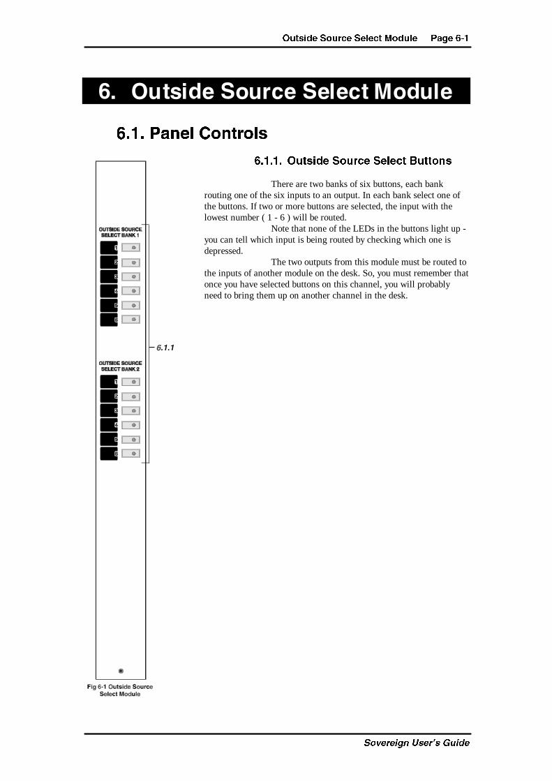
>dcbXST B^daRT BT[TRc <^Sd[T ?PVT %�
C_fUbUYW^ EcUb�c 7eYTU
%� >dcbXST�B^daRT�BT[TRc�<^Sd[T
%� � ?P]T[ 2^]ca^[b
%� � � >dcbXST B^daRT BT[TRc 1dcc^]b
There are two banks of six buttons, each bankrouting one of the six inputs to an output. In each bank select one ofthe buttons. If two or more buttons are selected, the input with thelowest number ( 1 - 6 ) will be routed.
Note that none of the LEDs in the buttons light up -you can tell which input is being routed by checking which one isdepressed.
The two outputs from this module must be routed tothe inputs of another module on the desk. So, you must remember thatonce you have selected buttons on this channel, you will probablyneed to bring them up on another channel in the desk.
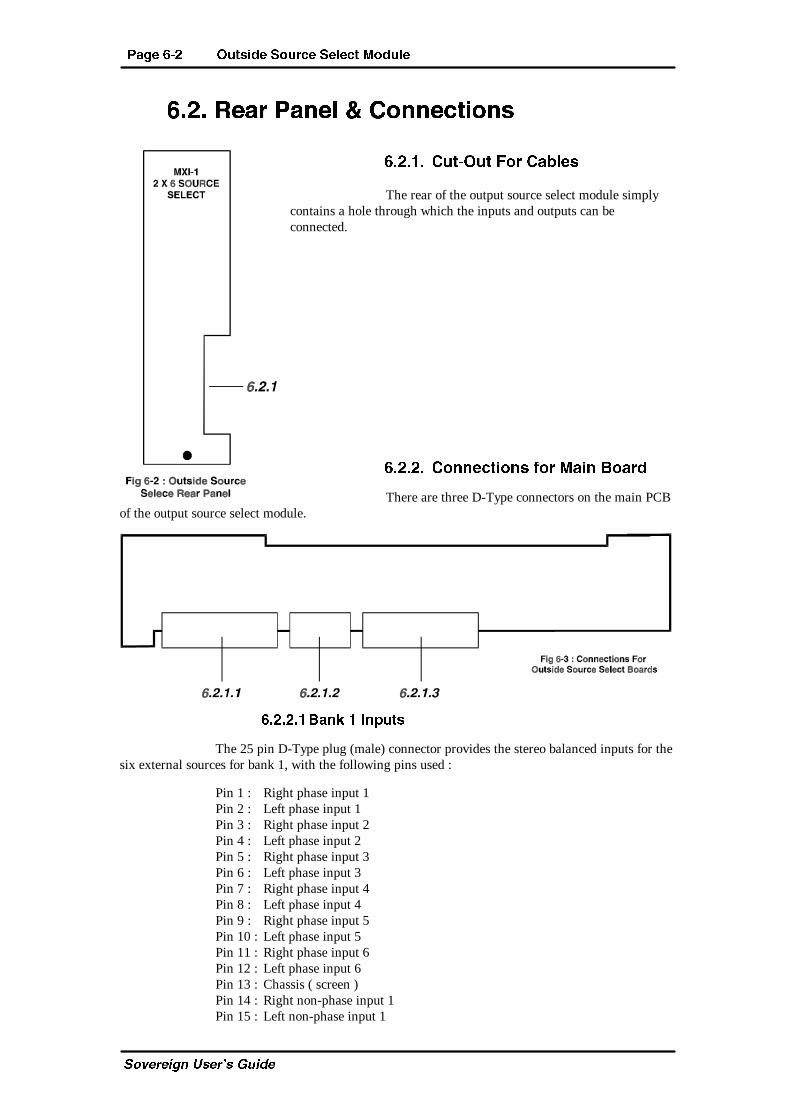
?PVT %�! >dcbXST B^daRT BT[TRc <^Sd[T
C_fUbUYW^ EcUb�c 7eYTU
%�!� ATPa ?P]T[ � 2^]]TRcX^]b
%�!� � 2dc�>dc 5^a 2PQ[Tb
The rear of the output source select module simplycontains a hole through which the inputs and outputs can beconnected.
%�!�!� 2^]]TRcX^]b U^a <PX] 1^PaS
There are three D-Type connectors on the main PCBof the output source select module.
%�!�!� 1P]Z 8]_dcb
The 25 pin D-Type plug (male) connector provides the stereo balanced inputs for thesix external sources for bank 1, with the following pins used :
Pin 1 : Right phase input 1Pin 2 : Left phase input 1Pin 3 : Right phase input 2Pin 4 : Left phase input 2Pin 5 : Right phase input 3Pin 6 : Left phase input 3Pin 7 : Right phase input 4Pin 8 : Left phase input 4Pin 9 : Right phase input 5Pin 10 : Left phase input 5Pin 11 : Right phase input 6Pin 12 : Left phase input 6Pin 13 : Chassis ( screen )Pin 14 : Right non-phase input 1Pin 15 : Left non-phase input 1
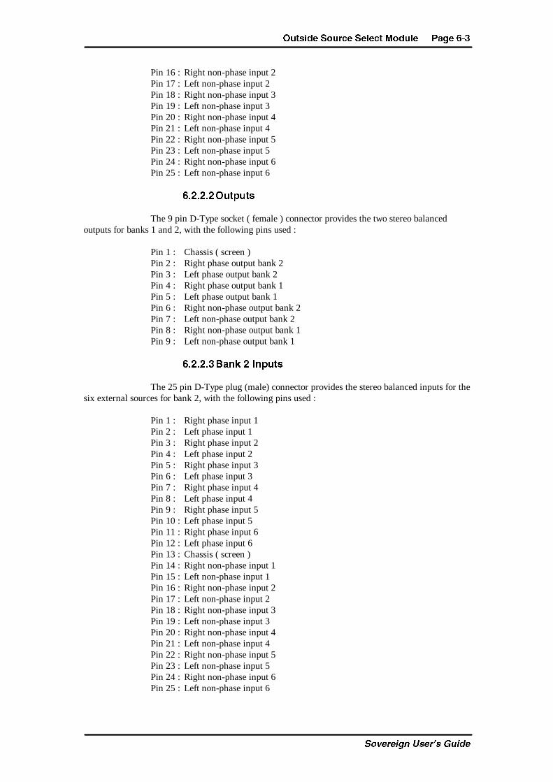
>dcbXST B^daRT BT[TRc <^Sd[T ?PVT %�"
C_fUbUYW^ EcUb�c 7eYTU
Pin 16 : Right non-phase input 2Pin 17 : Left non-phase input 2Pin 18 : Right non-phase input 3Pin 19 : Left non-phase input 3Pin 20 : Right non-phase input 4Pin 21 : Left non-phase input 4Pin 22 : Right non-phase input 5Pin 23 : Left non-phase input 5Pin 24 : Right non-phase input 6Pin 25 : Left non-phase input 6
%�!�!�! >dc_dcb
The 9 pin D-Type socket ( female ) connector provides the two stereo balancedoutputs for banks 1 and 2, with the following pins used :
Pin 1 : Chassis ( screen )Pin 2 : Right phase output bank 2Pin 3 : Left phase output bank 2Pin 4 : Right phase output bank 1Pin 5 : Left phase output bank 1Pin 6 : Right non-phase output bank 2Pin 7 : Left non-phase output bank 2Pin 8 : Right non-phase output bank 1Pin 9 : Left non-phase output bank 1
%�!�!�" 1P]Z ! 8]_dcb
The 25 pin D-Type plug (male) connector provides the stereo balanced inputs for thesix external sources for bank 2, with the following pins used :
Pin 1 : Right phase input 1Pin 2 : Left phase input 1Pin 3 : Right phase input 2Pin 4 : Left phase input 2Pin 5 : Right phase input 3Pin 6 : Left phase input 3Pin 7 : Right phase input 4Pin 8 : Left phase input 4Pin 9 : Right phase input 5Pin 10 : Left phase input 5Pin 11 : Right phase input 6Pin 12 : Left phase input 6Pin 13 : Chassis ( screen )Pin 14 : Right non-phase input 1Pin 15 : Left non-phase input 1Pin 16 : Right non-phase input 2Pin 17 : Left non-phase input 2Pin 18 : Right non-phase input 3Pin 19 : Left non-phase input 3Pin 20 : Right non-phase input 4Pin 21 : Left non-phase input 4Pin 22 : Right non-phase input 5Pin 23 : Left non-phase input 5Pin 24 : Right non-phase input 6Pin 25 : Left non-phase input 6

?PVT %�# >dcbXST B^daRT BT[TRc <^Sd[T
C_fUbUYW^ EcUb�c 7eYTU
This page is deliberately blank.
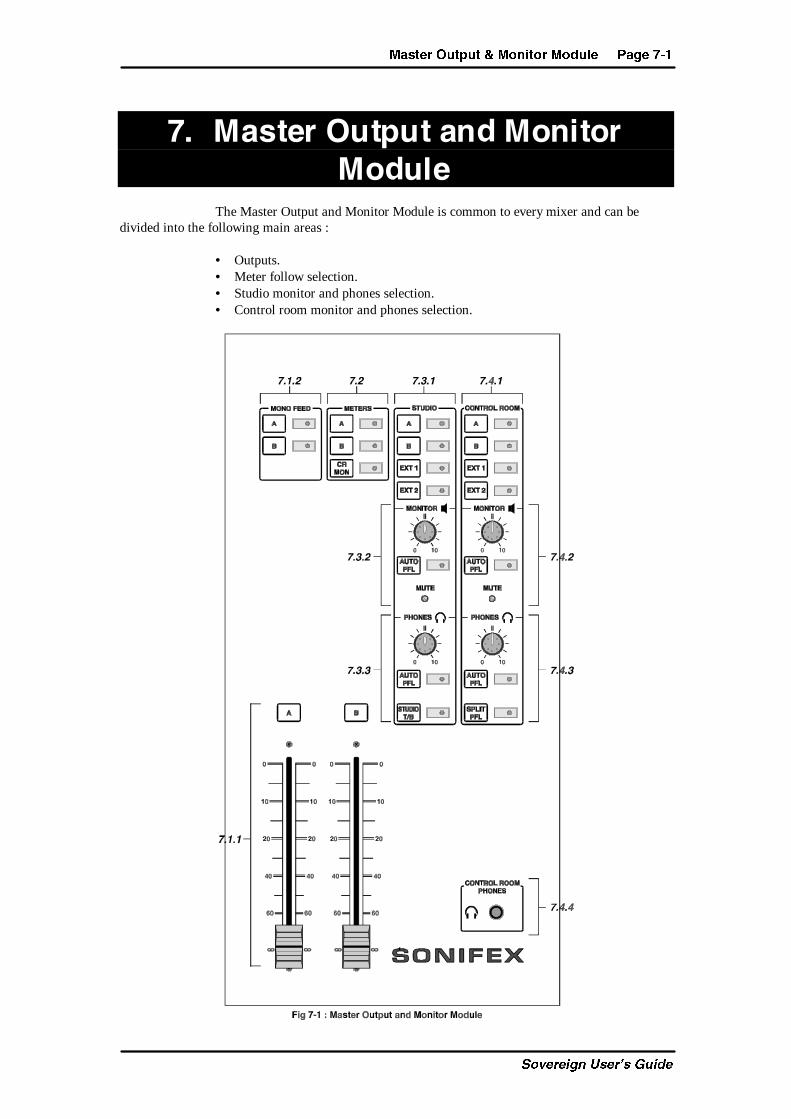
<PbcTa >dc_dc � <^]Xc^a <^Sd[T ?PVT &�
C_fUbUYW^ EcUb�c 7eYTU
&� <PbcTa�>dc_dc�P]S�<^]Xc^a
<^Sd[TThe Master Output and Monitor Module is common to every mixer and can be
divided into the following main areas :
• Outputs.• Meter follow selection.• Studio monitor and phones selection.• Control room monitor and phones selection.
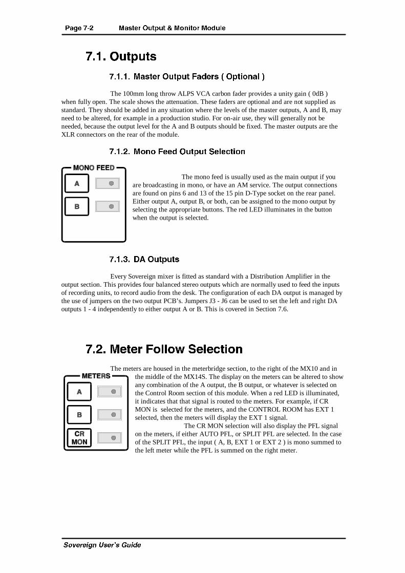
?PVT &�! <PbcTa >dc_dc � <^]Xc^a <^Sd[T
C_fUbUYW^ EcUb�c 7eYTU
&� � >dc_dcb
&� � � <PbcTa >dc_dc 5PSTab � >_cX^]P[ �
The 100mm long throw ALPS VCA carbon fader provides a unity gain ( 0dB )when fully open. The scale shows the attenuation. These faders are optional and are not supplied asstandard. They should be added in any situation where the levels of the master outputs, A and B, mayneed to be altered, for example in a production studio. For on-air use, they will generally not beneeded, because the output level for the A and B outputs should be fixed. The master outputs are theXLR connectors on the rear of the module.
&� �!� <^]^ 5TTS >dc_dc BT[TRcX^]
The mono feed is usually used as the main output if youare broadcasting in mono, or have an AM service. The output connectionsare found on pins 6 and 13 of the 15 pin D-Type socket on the rear panel.Either output A, output B, or both, can be assigned to the mono output byselecting the appropriate buttons. The red LED illuminates in the buttonwhen the output is selected.
&� �"� 30 >dc_dcb
Every Sovereign mixer is fitted as standard with a Distribution Amplifier in theoutput section. This provides four balanced stereo outputs which are normally used to feed the inputsof recording units, to record audio from the desk. The configuration of each DA output is managed bythe use of jumpers on the two output PCB’s. Jumpers J3 - J6 can be used to set the left and right DAoutputs 1 - 4 independently to either output A or B. This is covered in Section 7.6.
&�!� <TcTa 5^[[^f BT[TRcX^]
The meters are housed in the meterbridge section, to the right of the MX10 and inthe middle of the MX14S. The display on the meters can be altered to showany combination of the A output, the B output, or whatever is selected onthe Control Room section of this module. When a red LED is illuminated,it indicates that that signal is routed to the meters. For example, if CRMON is selected for the meters, and the CONTROL ROOM has EXT 1selected, then the meters will display the EXT 1 signal.
The CR MON selection will also display the PFL signalon the meters, if either AUTO PFL, or SPLIT PFL are selected. In the caseof the SPLIT PFL, the input ( A, B, EXT 1 or EXT 2 ) is mono summed tothe left meter while the PFL is summed on the right meter.
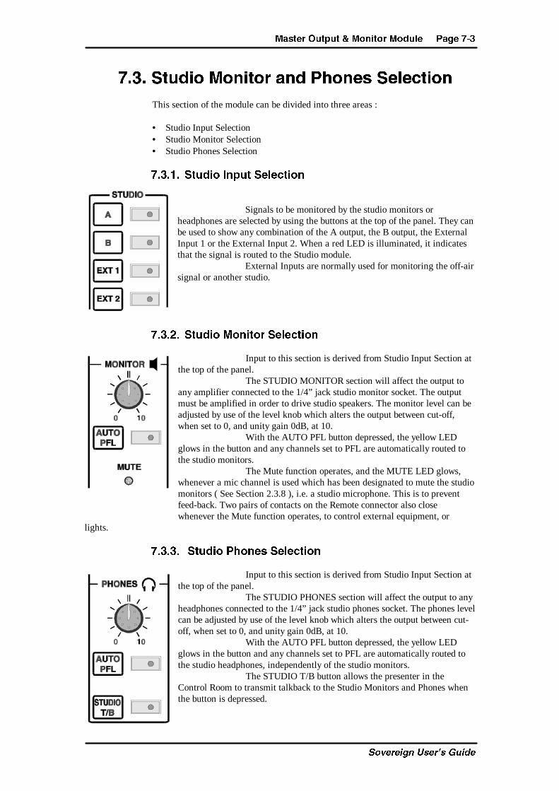
<PbcTa >dc_dc � <^]Xc^a <^Sd[T ?PVT &�"
C_fUbUYW^ EcUb�c 7eYTU
&�"� BcdSX^ <^]Xc^a P]S ?W^]Tb BT[TRcX^]
This section of the module can be divided into three areas :
• Studio Input Selection• Studio Monitor Selection• Studio Phones Selection
&�"� � BcdSX^ 8]_dc BT[TRcX^]
Signals to be monitored by the studio monitors orheadphones are selected by using the buttons at the top of the panel. They canbe used to show any combination of the A output, the B output, the ExternalInput 1 or the External Input 2. When a red LED is illuminated, it indicatesthat the signal is routed to the Studio module.
External Inputs are normally used for monitoring the off-airsignal or another studio.
&�"�!� BcdSX^ <^]Xc^a BT[TRcX^]
Input to this section is derived from Studio Input Section atthe top of the panel.
The STUDIO MONITOR section will affect the output toany amplifier connected to the 1/4” jack studio monitor socket. The outputmust be amplified in order to drive studio speakers. The monitor level can beadjusted by use of the level knob which alters the output between cut-off,when set to 0, and unity gain 0dB, at 10.
With the AUTO PFL button depressed, the yellow LEDglows in the button and any channels set to PFL are automatically routed tothe studio monitors.
The Mute function operates, and the MUTE LED glows,whenever a mic channel is used which has been designated to mute the studiomonitors ( See Section 2.3.8 ), i.e. a studio microphone. This is to preventfeed-back. Two pairs of contacts on the Remote connector also closewhenever the Mute function operates, to control external equipment, or
lights.
&�"�"� BcdSX^ ?W^]Tb BT[TRcX^]
Input to this section is derived from Studio Input Section atthe top of the panel.
The STUDIO PHONES section will affect the output to anyheadphones connected to the 1/4” jack studio phones socket. The phones levelcan be adjusted by use of the level knob which alters the output between cut-off, when set to 0, and unity gain 0dB, at 10.
With the AUTO PFL button depressed, the yellow LEDglows in the button and any channels set to PFL are automatically routed tothe studio headphones, independently of the studio monitors.
The STUDIO T/B button allows the presenter in theControl Room to transmit talkback to the Studio Monitors and Phones whenthe button is depressed.
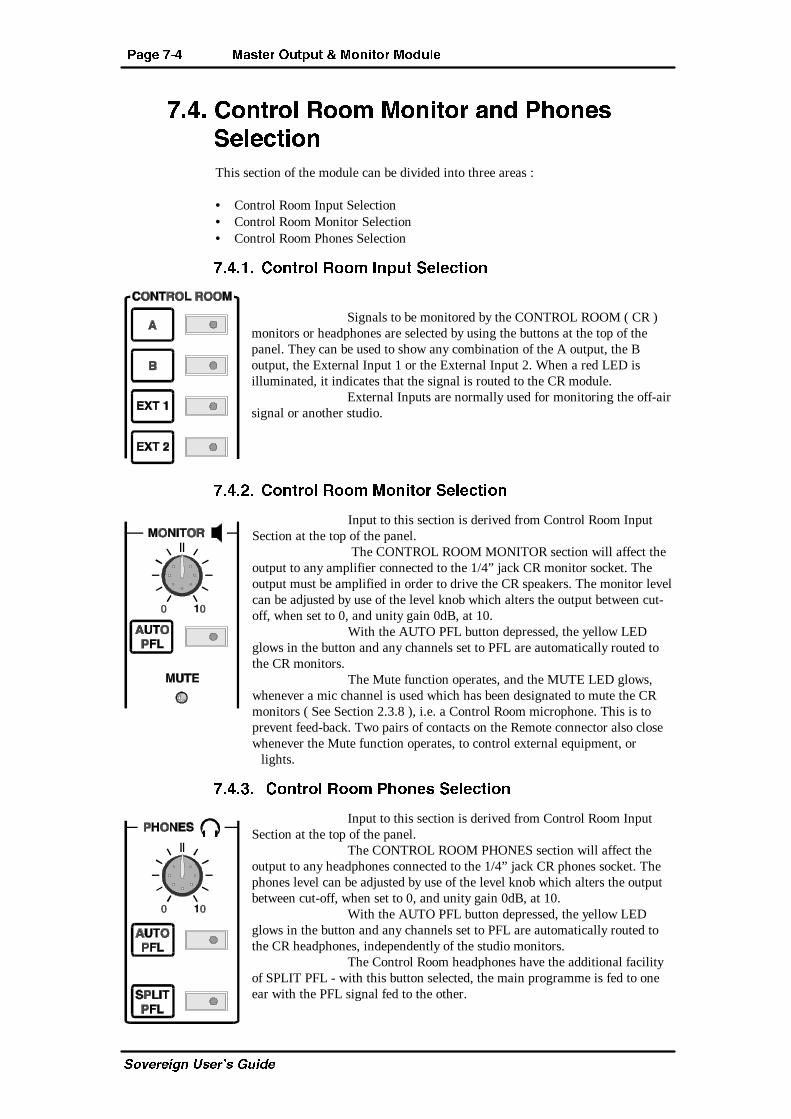
?PVT &�# <PbcTa >dc_dc � <^]Xc^a <^Sd[T
C_fUbUYW^ EcUb�c 7eYTU
&�#� 2^]ca^[ A^^\ <^]Xc^a P]S ?W^]Tb
BT[TRcX^]
This section of the module can be divided into three areas :
• Control Room Input Selection• Control Room Monitor Selection• Control Room Phones Selection
&�#� � 2^]ca^[ A^^\ 8]_dc BT[TRcX^]
Signals to be monitored by the CONTROL ROOM ( CR )monitors or headphones are selected by using the buttons at the top of thepanel. They can be used to show any combination of the A output, the Boutput, the External Input 1 or the External Input 2. When a red LED isilluminated, it indicates that the signal is routed to the CR module.
External Inputs are normally used for monitoring the off-airsignal or another studio.
&�#�!� 2^]ca^[ A^^\ <^]Xc^a BT[TRcX^]
Input to this section is derived from Control Room InputSection at the top of the panel.
The CONTROL ROOM MONITOR section will affect theoutput to any amplifier connected to the 1/4” jack CR monitor socket. Theoutput must be amplified in order to drive the CR speakers. The monitor levelcan be adjusted by use of the level knob which alters the output between cut-off, when set to 0, and unity gain 0dB, at 10.
With the AUTO PFL button depressed, the yellow LEDglows in the button and any channels set to PFL are automatically routed tothe CR monitors.
The Mute function operates, and the MUTE LED glows,whenever a mic channel is used which has been designated to mute the CRmonitors ( See Section 2.3.8 ), i.e. a Control Room microphone. This is toprevent feed-back. Two pairs of contacts on the Remote connector also closewhenever the Mute function operates, to control external equipment, or
lights.
&�#�"� 2^]ca^[ A^^\ ?W^]Tb BT[TRcX^]
Input to this section is derived from Control Room InputSection at the top of the panel.
The CONTROL ROOM PHONES section will affect theoutput to any headphones connected to the 1/4” jack CR phones socket. Thephones level can be adjusted by use of the level knob which alters the outputbetween cut-off, when set to 0, and unity gain 0dB, at 10.
With the AUTO PFL button depressed, the yellow LEDglows in the button and any channels set to PFL are automatically routed tothe CR headphones, independently of the studio monitors.
The Control Room headphones have the additional facilityof SPLIT PFL - with this button selected, the main programme is fed to oneear with the PFL signal fed to the other.
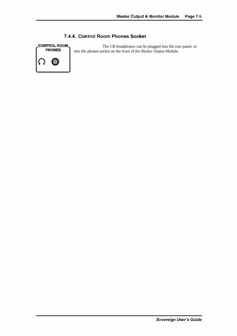
<PbcTa >dc_dc � <^]Xc^a <^Sd[T ?PVT &�$
C_fUbUYW^ EcUb�c 7eYTU
&�#�#� 2^]ca^[ A^^\ ?W^]Tb B^RZTc
The CR headphones can be plugged into the rear panel, orinto the phones socket on the front of the Master Output Module.
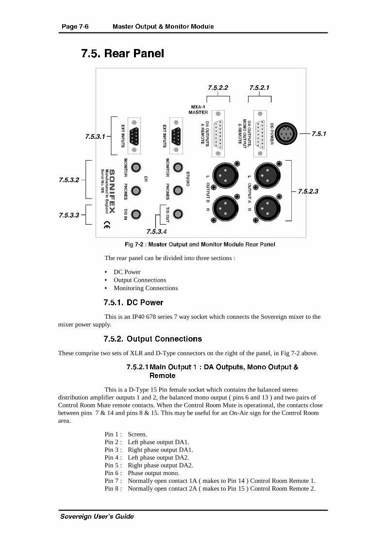
?PVT &�% <PbcTa >dc_dc � <^]Xc^a <^Sd[T
C_fUbUYW^ EcUb�c 7eYTU
&�$� ATPa ?P]T[
The rear panel can be divided into three sections :
• DC Power• Output Connections• Monitoring Connections
&�$� � 32 ?^fTa
This is an IP40 678 series 7 way socket which connects the Sovereign mixer to themixer power supply.
&�$�!� >dc_dc 2^]]TRcX^]b
These comprise two sets of XLR and D-Type connectors on the right of the panel, in Fig 7-2 above.
&�$�!� <PX] >dc_dc ) 30 >dc_dcb� <^]^ >dc_dc �AT\^cT
This is a D-Type 15 Pin female socket which contains the balanced stereodistribution amplifier outputs 1 and 2, the balanced mono output ( pins 6 and 13 ) and two pairs ofControl Room Mute remote contacts. When the Control Room Mute is operational, the contacts closebetween pins 7 & 14 and pins 8 & 15. This may be useful for an On-Air sign for the Control Roomarea.
Pin 1 : Screen.Pin 2 : Left phase output DA1.Pin 3 : Right phase output DA1.Pin 4 : Left phase output DA2.Pin 5 : Right phase output DA2.Pin 6 : Phase output mono.Pin 7 : Normally open contact 1A ( makes to Pin 14 ) Control Room Remote 1.Pin 8 : Normally open contact 2A ( makes to Pin 15 ) Control Room Remote 2.
<PbcTa >dc_dc � <^]Xc^a <^Sd[T ?PVT &�&
C_fUbUYW^ EcUb�c 7eYTU
Pin 9 : Left non-phase output DA1.Pin 10 : Right non-phase output DA1.Pin 11 : Left non-phase output DA2.Pin 12 : Right non-phase output DA2.Pin 13 : Non-phase output mono.Pin 14 : Normally open contact 1B ( makes to Pin 7 ) Control Room Remote 1.Pin 15 : Normally open contact 2B ( makes to Pin 8 ) Control Room Remote 2.
&�$�!�! <PX] >dc_dc ! ) 30 >dc_dcb P]S AT\^cT
Distribution Amplifier : This is a D-Type 15 Pin female socket which containsbalanced stereo distribution amplifier outputs 3 and 4, and two pairs of Studio Mute remote contacts.When the Studio Mute is operational, the contacts close between pins 7 & 14 and pins 8 & 15. Thismay be useful for an On-Air sign for the Studio area.
Pin 1 : Screen.Pin 2 : Left phase output DA3.Pin 3 : Right phase output DA3.Pin 4 : Left phase output DA4.Pin 5 : Right phase output DA4.Pin 6 : N/CPin 7 : Normally open contact 1A ( makes to Pin 14 ) Studio Remote 1.Pin 8 : Normally open contact 2A ( makes to Pin 15 ) Studio Remote 2.Pin 9 : Left non-phase output DA3.Pin 10 : Right non-phase output DA3.Pin 11 : Left non-phase output DA4.Pin 12 : Right non-phase output DA4.Pin 13 : N/CPin 14 : Normally open contact 1B ( makes to Pin 7 ) Studio Remote 1.Pin 15 : Normally open contact 2B ( makes to Pin 8 ) Studio Remote 2.
&�$�!�" <PbcTa 0 P]S 1� ;TUc P]S AXVWc >dc_dcb
These XLR 3 pin plugs are the two master bus balanced stereo outputs A and B, asreferenced by the output selection buttons along the top of the input channels. Any channel with A, orB, selected will be routed to the respective output.
Pin 1 : ScreenPin 2 : PhasePin 3 : Non-phase
Important Note : When the Transmission Router Module is fitted, the main AOutput should be taken from the rear of the Router Module, not from the Master A Output. This isbecause the external signals are not routed through the Output Module and so do not appear at theseoutputs.
&�$�"� <^]Xc^aX]V 2^]]TRcX^]b
These comprise of two sets of jack sockets and D-Type connectors on the left of thepanel, in Fig 7-2.
&�$�"� 4gcTa]P[ 8]_dcb � BcdSX^ P]S 2^]ca^[ A^^\ �
This D-Type 9 Pin male plug contains the balanced stereo External Inputs for theStudio and Control Room. The Studio and Control Room connectors have the same pin connectiondetails.
Pin 1 : Screen.Pin 2 : Ext 1 Left phase.
?PVT &�' <PbcTa >dc_dc � <^]Xc^a <^Sd[T
C_fUbUYW^ EcUb�c 7eYTU
Pin 3 : Ext 1 Right phase.Pin 4 : Ext 2 Left phase.Pin 5 : Ext 2 Right phase.Pin 6 : Ext 1 Left non-phase.Pin 7 : Ext 1 Right non-phase.Pin 8 : Ext 2 Left non-phase.Pin 9 : Ext 2 Right non-phase.
&�$�"�! <^]Xc^a P]S ?W^]Tb � BcdSX^ P]S 2^]ca^[ A^^\ �
The 1/4” ‘A’ gauge stereo jack sockets provide separate outputs for the Studio andControl Room monitor and phones outputs. Control Room headphones can also be plugged into thefront panel of this module.
Tip : Left Signal.Ring : Right Signal.Sleeve : Screen.
&�$�"�" C�1 8] � 2^]ca^[ A^^\ �
The 1/4” ‘A’ gauge stereo jack socket provides the Reverse Talkback Input for theControl Room.
Tip : Signal Phase ( unbalanced ).Ring : Control input make to sleeve.Sleeve : Common ( screen, non-phase ).
&�$�"�# C�1 >dc � BcdSX^ �
The 1/4” ‘A’ gauge stereo jack socket provides the Talkback output from the Studio.
Tip : Signal Phase.Ring : Control output. Switch makes to sleeve internallySleeve : Screen
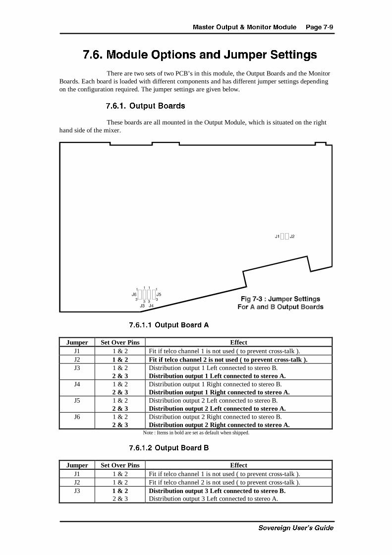
<PbcTa >dc_dc � <^]Xc^a <^Sd[T ?PVT &�(
C_fUbUYW^ EcUb�c 7eYTU
&�%� <^Sd[T >_cX^]b P]S 9d\_Ta BTccX]Vb
There are two sets of two PCB’s in this module, the Output Boards and the MonitorBoards. Each board is loaded with different components and has different jumper settings dependingon the configuration required. The jumper settings are given below.
&�%� � >dc_dc 1^PaSb
These boards are all mounted in the Output Module, which is situated on the righthand side of the mixer.
&�%� � >dc_dc 1^PaS 0
Jumper Set Over Pins EffectJ1 1 & 2 Fit if telco channel 1 is not used ( to prevent cross-talk ).J2 1 & 2 Fit if telco channel 2 is not used ( to prevent cross-talk ).J3 1 & 2
2 & 3Distribution output 1 Left connected to stereo B.Distribution output 1 Left connected to stereo A.
J4 1 & 22 & 3
Distribution output 1 Right connected to stereo B.Distribution output 1 Right connected to stereo A.
J5 1 & 22 & 3
Distribution output 2 Left connected to stereo B.Distribution output 2 Left connected to stereo A.
J6 1 & 22 & 3
Distribution output 2 Right connected to stereo B.Distribution output 2 Right connected to stereo A.
Note : Items in bold are set as default when shipped.
&�%� �! >dc_dc 1^PaS 1
Jumper Set Over Pins EffectJ1 1 & 2 Fit if telco channel 1 is not used ( to prevent cross-talk ).J2 1 & 2 Fit if telco channel 2 is not used ( to prevent cross-talk ).J3 1 & 2
2 & 3Distribution output 3 Left connected to stereo B.Distribution output 3 Left connected to stereo A.
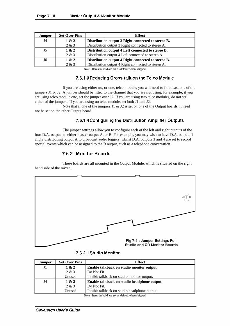
?PVT &� � <PbcTa >dc_dc � <^]Xc^a <^Sd[T
C_fUbUYW^ EcUb�c 7eYTU
Jumper Set Over Pins EffectJ4 1 & 2
2 & 3Distribution output 3 Right connected to stereo B.Distribution output 3 Right connected to stereo A.
J5 1 & 22 & 3
Distribution output 4 Left connected to stereo B.Distribution output 4 Left connected to stereo A.
J6 1 & 22 & 3
Distribution output 4 Right connected to stereo B.Distribution output 4 Right connected to stereo A.
Note : Items in bold are set as default when shipped.
&�%� �" ATSdRX]V 2a^bb�cP[Z ^] cWT CT[R^ <^Sd[T
If you are using either no, or one, telco module, you will need to fit atleast one of thejumpers J1 or J2. A jumper should be fitted to the channel that you are not using, for example, if youare using telco module one, set the jumper over J2. If you are using two telco modules, do not seteither of the jumpers. If you are using no telco module, set both J1 and J2.
Note that if one of the jumpers J1 or J2 is set on one of the Output boards, it neednot be set on the other Output board.
&�%� �# 2^]UXVdaX]V cWT 3XbcaXQdcX^] 0\_[XUXTa >dc_dcb
The jumper settings allow you to configure each of the left and right outputs of thefour D.A. outputs to either master output A, or B. For example, you may wish to have D.A. outputs 1and 2 distributing output A to broadcast audio loggers, whilst D.A. outputs 3 and 4 are set to recordspecial events which can be assigned to the B output, such as a telephone conversation.
&�%�!� <^]Xc^a 1^PaSb
These boards are all mounted in the Output Module, which is situated on the righthand side of the mixer.
&�%�!� BcdSX^ <^]Xc^a
Jumper Set Over Pins EffectJ1 1 & 2
2 & 3Unused
Enable talkback on studio monitor output.Do Not Fit.Inhibit talkback on studio monitor output.
J4 1 & 22 & 3
Unused
Enable talkback on studio headphone output.Do Not Fit.Inhibit talkback on studio headphone output.
Note : Items in bold are set as default when shipped.
<PbcTa >dc_dc � <^]Xc^a <^Sd[T ?PVT &�
C_fUbUYW^ EcUb�c 7eYTU
&�%�!�! 2^]ca^[ A^^\ � 2A � <^]Xc^a
Jumper Set Over Pins EffectJ1 1 & 2
2 & 3Unused
Do Not Fit.Enable talkback on control room monitor output.Inhibit talkback on control room monitor output.
J4 1 & 22 & 3
Unused
Do Not Fit.Enable talkback on control room headphone output.Inhibit talkback on control room headphone output.
Note : Items in bold are set as default when shipped.
&�%�!�" 8]WXQXcX]V P]S 4]PQ[X]V CP[ZQPRZ
If you require talkback to be used between the Control Room and Studio you willneed to set jumpers J1 and J4 over pins 1 & 2 on the studio monitor board and over pins 2 & 3 on theControl Room monitor board.
To inhibit the talkback for the Control Room or Studio, do not fit jumpers J1 and J4.
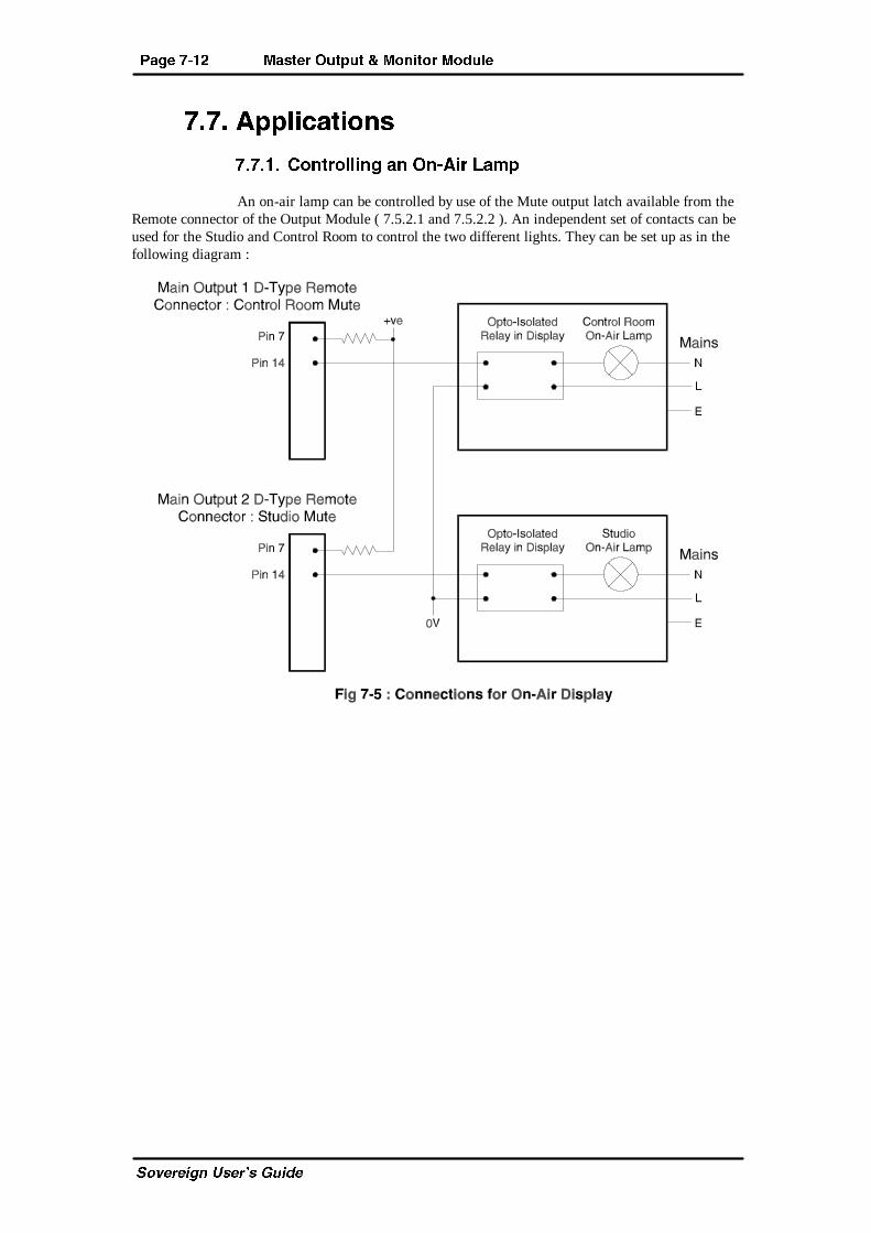
?PVT &� ! <PbcTa >dc_dc � <^]Xc^a <^Sd[T
C_fUbUYW^ EcUb�c 7eYTU
&�&� 0__[XRPcX^]b
&�&� � 2^]ca^[[X]V P] >]�0Xa ;P\_
An on-air lamp can be controlled by use of the Mute output latch available from theRemote connector of the Output Module ( 7.5.2.1 and 7.5.2.2 ). An independent set of contacts can beused for the Studio and Control Room to control the two different lights. They can be set up as in thefollowing diagram :
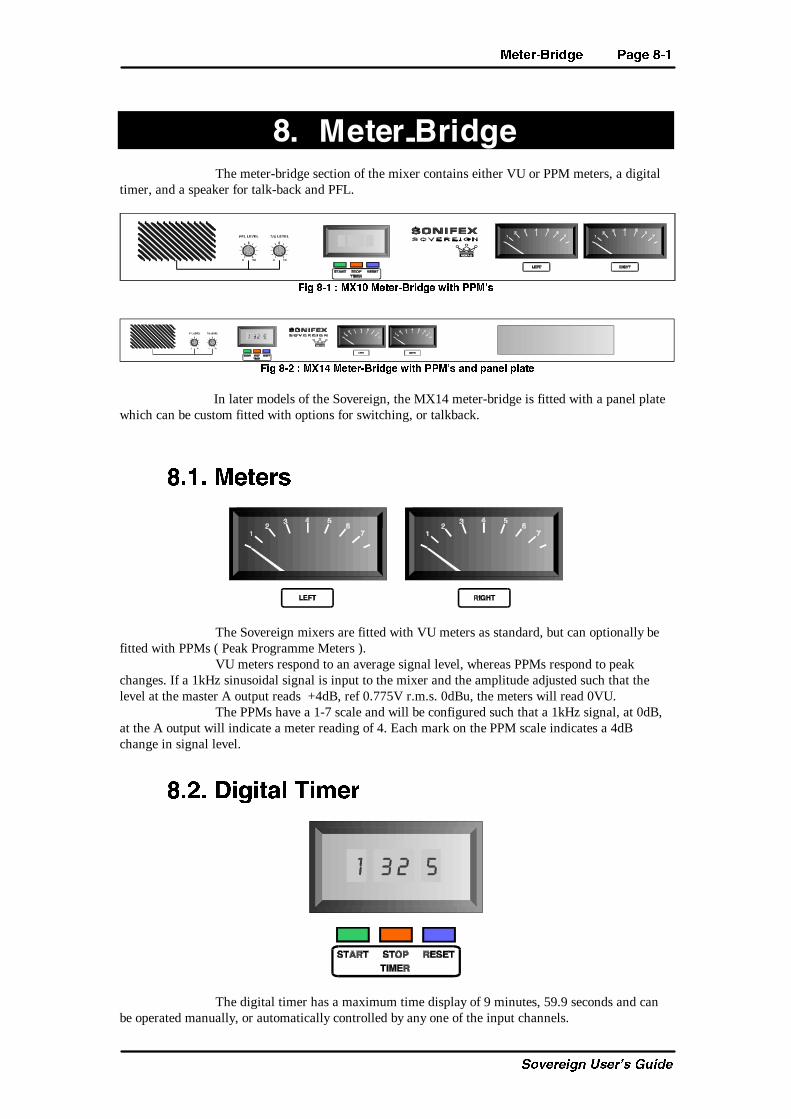
<TcTa�1aXSVT ?PVT '�
C_fUbUYW^ EcUb�c 7eYTU
'� <TcTa�1aXSVTThe meter-bridge section of the mixer contains either VU or PPM meters, a digital
timer, and a speaker for talk-back and PFL.
5XV '� ) <G � <TcTa�1aXSVT fXcW ??<´b
5XV '�! ) <G # <TcTa�1aXSVT fXcW ??<´b P]S _P]T[ _[PcT
In later models of the Sovereign, the MX14 meter-bridge is fitted with a panel platewhich can be custom fitted with options for switching, or talkback.
'� � <TcTab
The Sovereign mixers are fitted with VU meters as standard, but can optionally befitted with PPMs ( Peak Programme Meters ).
VU meters respond to an average signal level, whereas PPMs respond to peakchanges. If a 1kHz sinusoidal signal is input to the mixer and the amplitude adjusted such that thelevel at the master A output reads +4dB, ref 0.775V r.m.s. 0dBu, the meters will read 0VU.
The PPMs have a 1-7 scale and will be configured such that a 1kHz signal, at 0dB,at the A output will indicate a meter reading of 4. Each mark on the PPM scale indicates a 4dBchange in signal level.
'�!� 3XVXcP[ CX\Ta
The digital timer has a maximum time display of 9 minutes, 59.9 seconds and canbe operated manually, or automatically controlled by any one of the input channels.
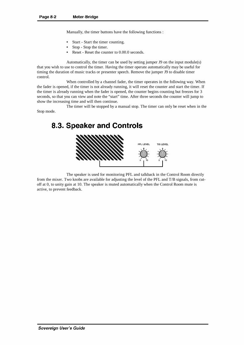
?PVT '�! <TcTa�1aXSVT
C_fUbUYW^ EcUb�c 7eYTU
Manually, the timer buttons have the following functions :
• Start - Start the timer counting.• Stop - Stop the timer.• Reset - Reset the counter to 0.00.0 seconds.
Automatically, the timer can be used by setting jumper J9 on the input module(s)that you wish to use to control the timer. Having the timer operate automatically may be useful fortiming the duration of music tracks or presenter speech. Remove the jumper J9 to disable timercontrol.
When controlled by a channel fader, the timer operates in the following way. Whenthe fader is opened, if the timer is not already running, it will reset the counter and start the timer. Ifthe timer is already running when the fader is opened, the counter begins counting but freezes for 3seconds, so that you can view and note the “start” time. After three seconds the counter will jump toshow the increasing time and will then continue.
The timer will be stopped by a manual stop. The timer can only be reset when in theStop mode.
'�"� B_TPZTa P]S 2^]ca^[b
The speaker is used for monitoring PFL and talkback in the Control Room directlyfrom the mixer. Two knobs are available for adjusting the level of the PFL and T/B signals, from cut-off at 0, to unity gain at 10. The speaker is muted automatically when the Control Room mute isactive, to prevent feedback.
B_TRXUXRPcX^]b ?PVT (�
C_fUbUYW^ EcUb�c 7eYTU
(� B_TRXUXRPcX^]b
(� � CTRW]XRP[ B_TRXUXRPcX^]b
(� � � 8]_dc�>dc_dc 8\_TSP]RTb
Mic Input : > 1.5k ohms electronically balanced.Mono line input : > 10k ohms electronically balanced.Stereo line input : > 10k ohms electronically balanced.Main Output : < 75ohm electronically balanced.Monitor Output : < 75 ohm unbalanced.
(� �!� 5aT`dT]Rh ATb_^]bT
Mic Input : 40Hz to 20kHz at -1dB, +0.Line Inputs : 20Hz to 20kHz at -0.5dB, +0.Gram Amp Option : 30Hz to 16kHz ± 1.5dB RIAA equalised
(� �"� =^XbT � !�7i c^ !�Z7i �
Mic Input E.I.N. : -128dB with 200 ohm source.Stereo Inputs : -100dB ( ref +8dB ).
(� �#� 3Xbc^acX^]
Total Harmonic 0.015% at 1kHz, 0dBu.Distortion : 0.025% at 10kHz, 0dBu.
(� �$� 2a^bbcP[Z
Inter-channel : -85dBu.Left-right : -88dBu at 1kHz.
-68dBu at 10kHz.
(� �%� 4@
LF : ± 7.5dB shelving at 100Hz.HF : ± 7.5dB shelving at 8kHz.
(� �&� 2^\\^] <^ST ATYTRcX^] APcX^
Mic Input : >100dB at 70dB gain.
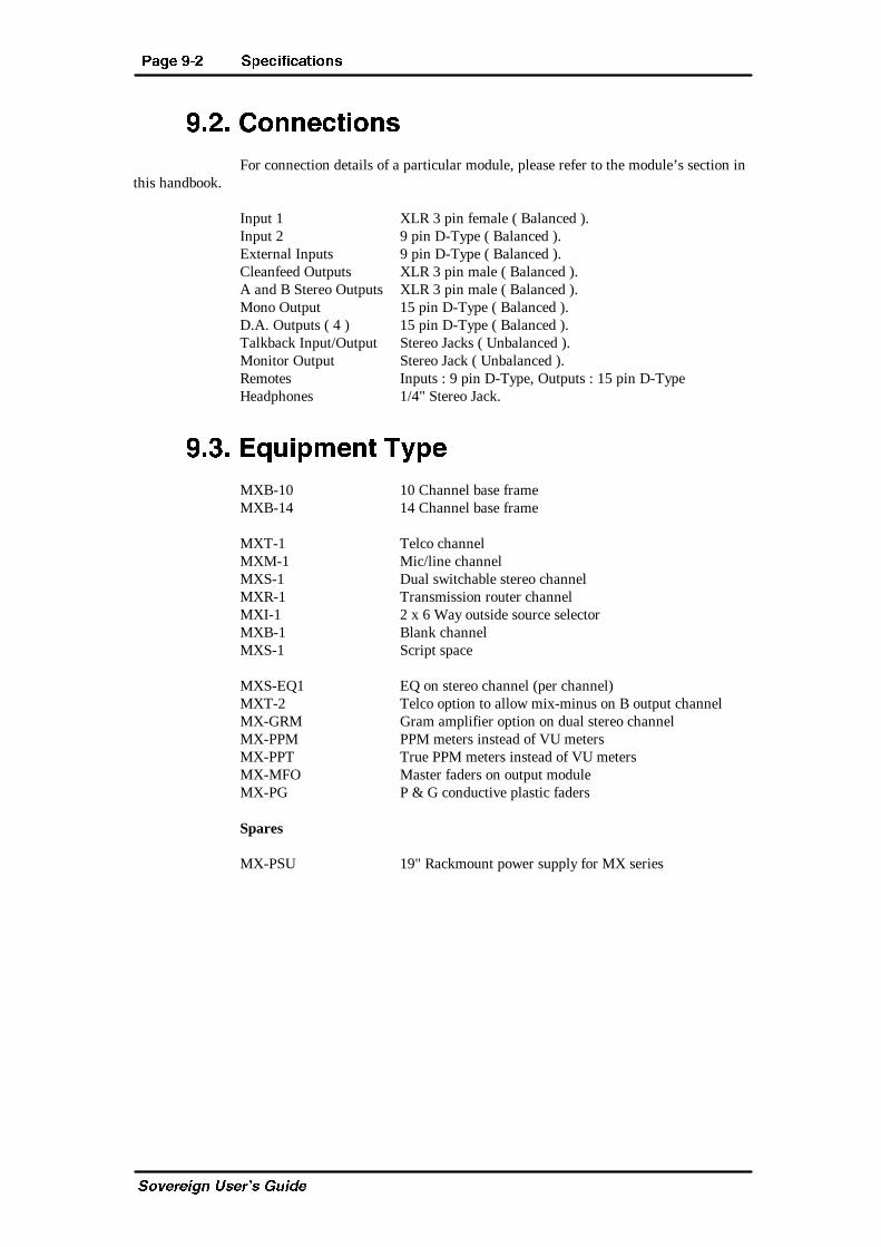
?PVT (�! B_TRXUXRPcX^]b
C_fUbUYW^ EcUb�c 7eYTU
(�!� 2^]]TRcX^]bFor connection details of a particular module, please refer to the module’s section in
this handbook.
Input 1 XLR 3 pin female ( Balanced ).Input 2 9 pin D-Type ( Balanced ).External Inputs 9 pin D-Type ( Balanced ).Cleanfeed Outputs XLR 3 pin male ( Balanced ).A and B Stereo Outputs XLR 3 pin male ( Balanced ).Mono Output 15 pin D-Type ( Balanced ).D.A. Outputs ( 4 ) 15 pin D-Type ( Balanced ).Talkback Input/Output Stereo Jacks ( Unbalanced ).Monitor Output Stereo Jack ( Unbalanced ).Remotes Inputs : 9 pin D-Type, Outputs : 15 pin D-TypeHeadphones 1/4" Stereo Jack.
(�"� 4`dX_\T]c Ch_T
MXB-10 10 Channel base frameMXB-14 14 Channel base frame
MXT-1 Telco channelMXM-1 Mic/line channelMXS-1 Dual switchable stereo channelMXR-1 Transmission router channelMXI-1 2 x 6 Way outside source selectorMXB-1 Blank channelMXS-1 Script space
MXS-EQ1 EQ on stereo channel (per channel)MXT-2 Telco option to allow mix-minus on B output channelMX-GRM Gram amplifier option on dual stereo channelMX-PPM PPM meters instead of VU metersMX-PPT True PPM meters instead of VU metersMX-MFO Master faders on output moduleMX-PG P & G conductive plastic faders
Spares
MX-PSU 19" Rackmount power supply for MX series
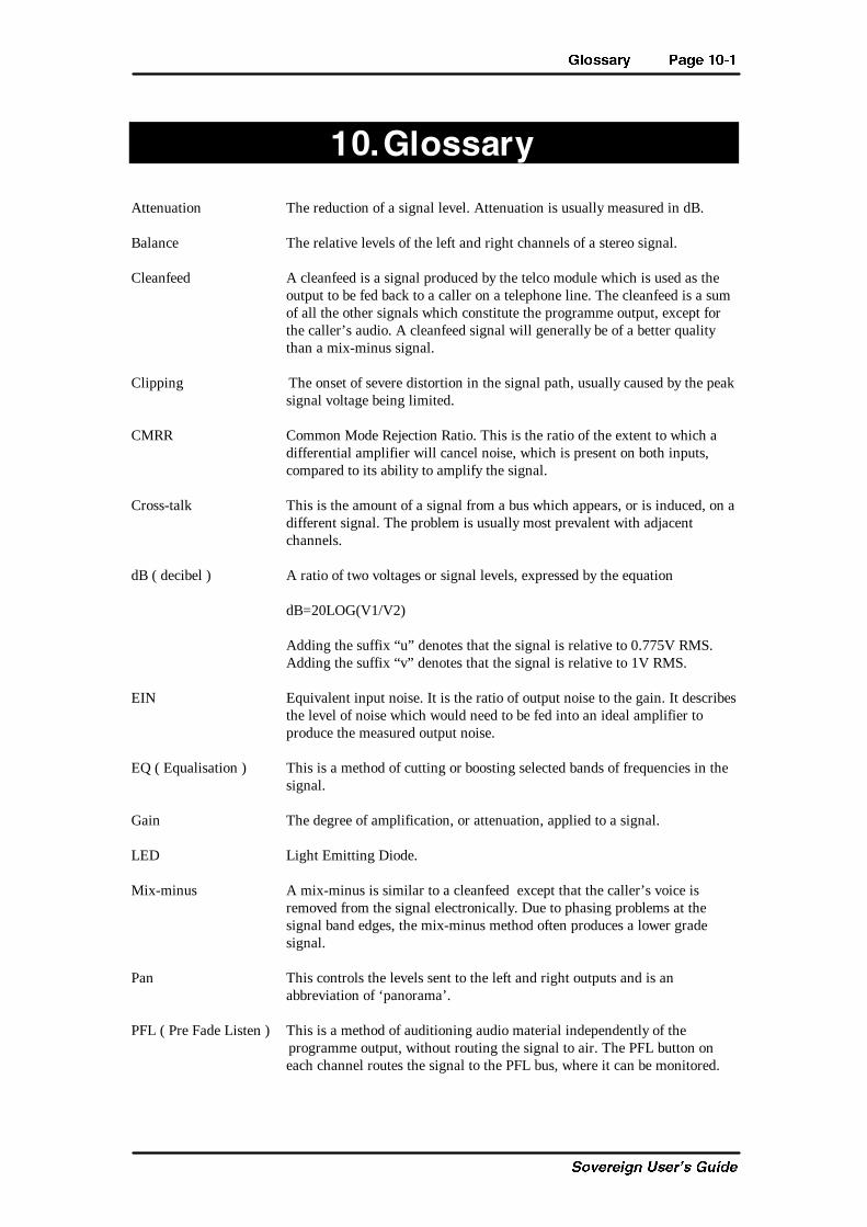
6[^bbPah ?PVT ��
C_fUbUYW^ EcUb�c 7eYTU
�� 6[^bbPah
Attenuation The reduction of a signal level. Attenuation is usually measured in dB.
Balance The relative levels of the left and right channels of a stereo signal.
Cleanfeed A cleanfeed is a signal produced by the telco module which is used as theoutput to be fed back to a caller on a telephone line. The cleanfeed is a sumof all the other signals which constitute the programme output, except forthe caller’s audio. A cleanfeed signal will generally be of a better qualitythan a mix-minus signal.
Clipping The onset of severe distortion in the signal path, usually caused by the peaksignal voltage being limited.
CMRR Common Mode Rejection Ratio. This is the ratio of the extent to which adifferential amplifier will cancel noise, which is present on both inputs,compared to its ability to amplify the signal.
Cross-talk This is the amount of a signal from a bus which appears, or is induced, on adifferent signal. The problem is usually most prevalent with adjacentchannels.
dB ( decibel ) A ratio of two voltages or signal levels, expressed by the equation
dB=20LOG(V1/V2)
Adding the suffix “u” denotes that the signal is relative to 0.775V RMS.Adding the suffix “v” denotes that the signal is relative to 1V RMS.
EIN Equivalent input noise. It is the ratio of output noise to the gain. It describesthe level of noise which would need to be fed into an ideal amplifier toproduce the measured output noise.
EQ ( Equalisation ) This is a method of cutting or boosting selected bands of frequencies in thesignal.
Gain The degree of amplification, or attenuation, applied to a signal.
LED Light Emitting Diode.
Mix-minus A mix-minus is similar to a cleanfeed except that the caller’s voice isremoved from the signal electronically. Due to phasing problems at thesignal band edges, the mix-minus method often produces a lower gradesignal.
Pan This controls the levels sent to the left and right outputs and is anabbreviation of ‘panorama’.
PFL ( Pre Fade Listen ) This is a method of auditioning audio material independently of the programme output, without routing the signal to air. The PFL button oneach channel routes the signal to the PFL bus, where it can be monitored.
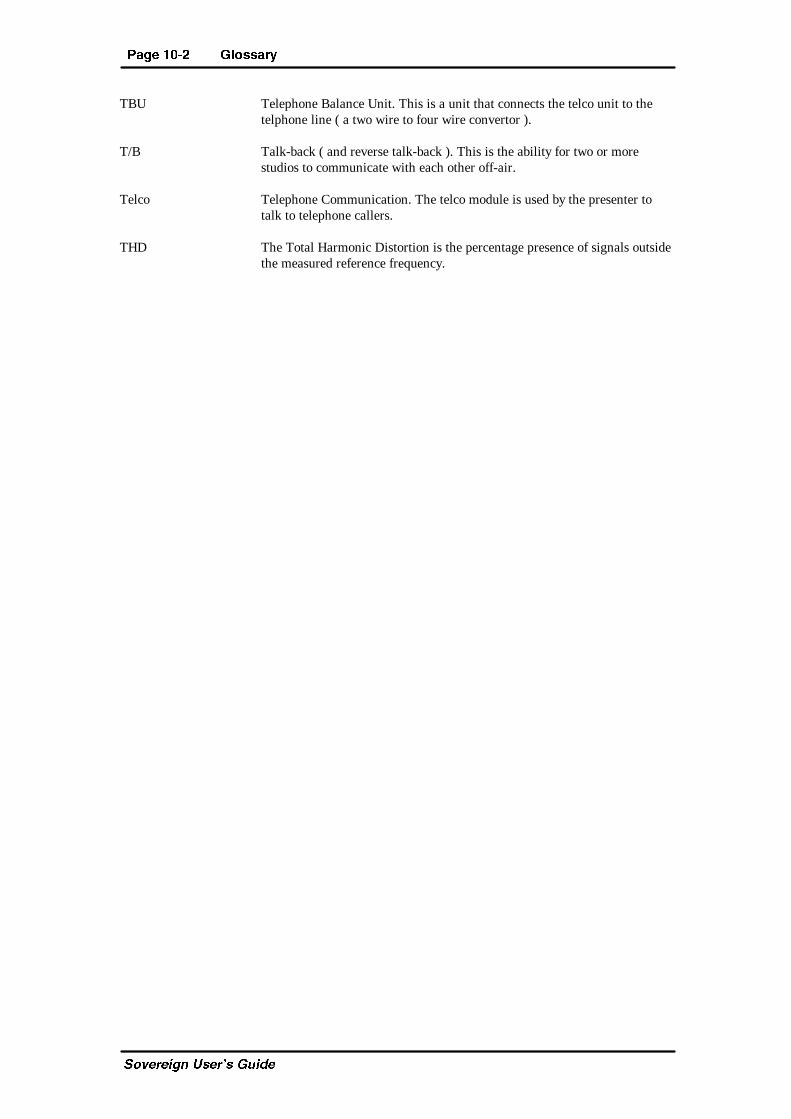
?PVT ��! 6[^bbPah
C_fUbUYW^ EcUb�c 7eYTU
TBU Telephone Balance Unit. This is a unit that connects the telco unit to thetelphone line ( a two wire to four wire convertor ).
T/B Talk-back ( and reverse talk-back ). This is the ability for two or morestudios to communicate with each other off-air.
Telco Telephone Communication. The telco module is used by the presenter totalk to telephone callers.
THD The Total Harmonic Distortion is the percentage presence of signals outsidethe measured reference frequency.
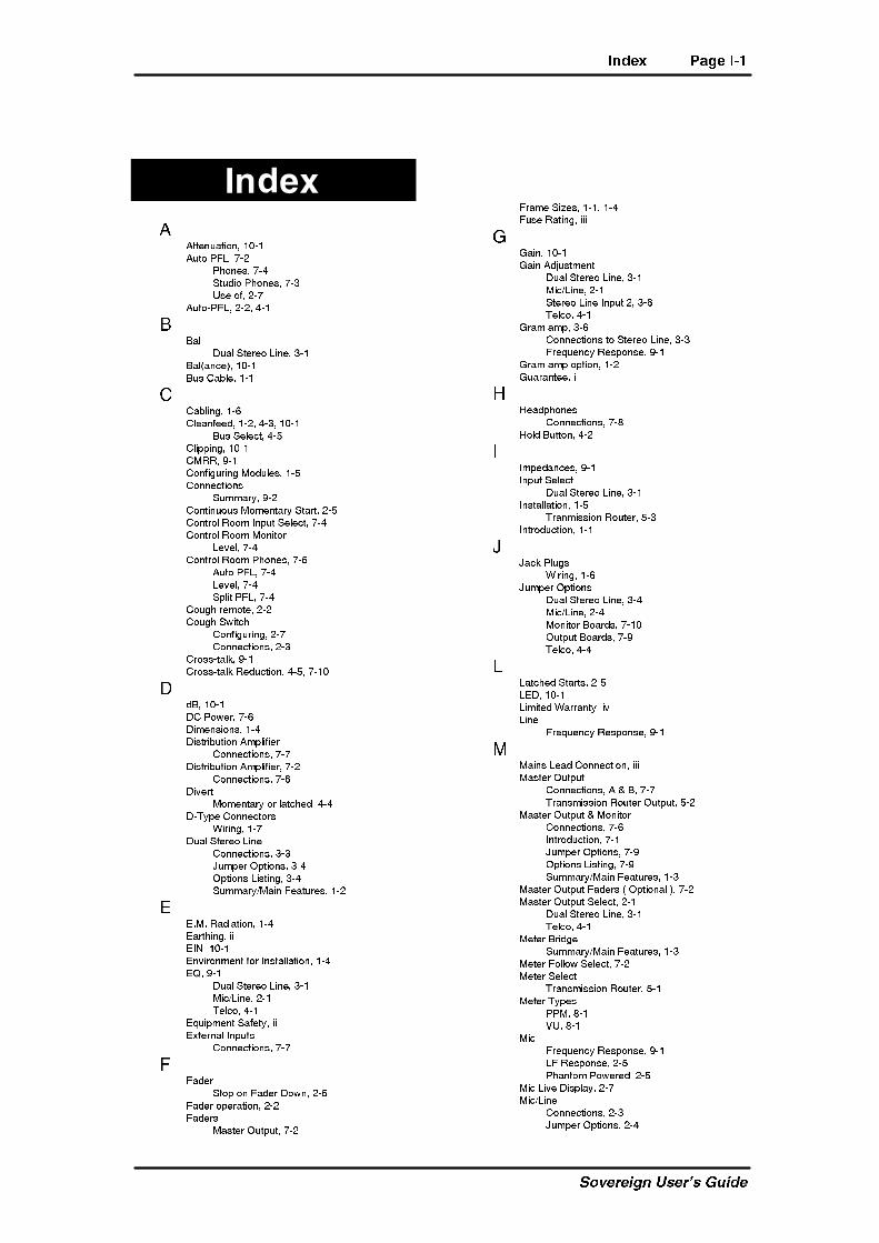
8]STg ?PVT 8�
C_fUbUYW^ EcUb�c 7eYTU
8]STg
11ddU^eQdY_^� ! �!
1ed_ @6<� '�"
@X_^Uc� '�$
CdeTY_ @X_^Uc� '�#
EcU _V� "�'
1ed_�@6<� "�"� $�!
22Q\
4eQ\ CdUbU_ <Y^U� #�!
2Q\�Q^SU�� ! �!
2ec 3QR\U� !�!
33QR\Y^W� !�&
3\UQ^VUUT� !�"� $�#� ! �!
2ec CU\USd� $�%
3\Y``Y^W� ! �!
3=BB� )�!
3_^VYWebY^W =_Te\Uc� !�%
3_^^USdY_^c
Ce]]Qbi� )�"
3_^dY^e_ec =_]U^dQbi CdQbd� "�%
3_^db_\ B__] 9^`ed CU\USd� '�$
3_^db_\ B__] =_^Yd_b
<UfU\� '�$
3_^db_\ B__] @X_^Uc� '�%
1ed_ @6<� '�$
<UfU\� '�$
C`\Yd @6<� '�$
3_eWX bU]_dU� "�"
3_eWX CgYdSX
3_^VYWebY^W� "�'
3_^^USdY_^c� "�#
3b_cc�dQ\[� )�!
3b_cc�dQ\[ BUTeSdY_^� $�%� '�!
4T2� ! �!
43 @_gUb� '�&
4Y]U^cY_^c� !�$
4YcdbYRedY_^ 1]`\YVYUb
3_^^USdY_^c� '�'
4YcdbYRedY_^ 1]`\YVYUb� '�"
3_^^USdY_^c� '�&
4YfUbd
=_]U^dQbi _b \QdSXUT� $�$
4�Di`U 3_^^USd_bc
GYbY^W� !�'
4eQ\ CdUbU_ <Y^U
3_^^USdY_^c� #�#
:e]`Ub ?`dY_^c� #�$
?`dY_^c <YcdY^W� #�$
Ce]]Qbi�=QY^ 6UQdebUc� !�"
55�=� BQTYQdY_^� !�$
5QbdXY^W� YY
59>� ! �!
5^fYb_^]U^d V_b 9^cdQ\\QdY_^� !�$
5A� )�!
4eQ\ CdUbU_ <Y^U� #�!
=YS�<Y^U� "�!
DU\S_� $�!
5aeY`]U^d CQVUdi� YY
5hdUb^Q\ 9^`edc
3_^^USdY_^c� '�'
66QTUb
Cd_` _^ 6QTUb 4_g^� "�%
6QTUb _`UbQdY_^� "�"
6QTUbc
=QcdUb ?ed`ed� '�"
6bQ]U CYjUc� !�!� !�$
6ecU BQdY^W� YYY
77QY^� ! �!
7QY^ 1TZecd]U^d
4eQ\ CdUbU_ <Y^U� #�!
=YS�<Y^U� "�!
CdUbU_ <Y^U 9^`ed "� #�&
DU\S_� $�!
7bQ] Q]`� #�&
3_^^USdY_^c d_ CdUbU_ <Y^U� #�#
6bUaeU^Si BUc`_^cU� )�!
7bQ] Q]` _`dY_^� !�"
7eQbQ^dUU� Y
88UQT`X_^Uc
3_^^USdY_^c� '�(
8_\T 2edd_^� $�"
99]`UTQ^SUc� )�!
9^`ed CU\USd
4eQ\ CdUbU_ <Y^U� #�!
9^cdQ\\QdY_^� !�%
DbQ^]YccY_^ B_edUb� %�#
9^db_TeSdY_^� !�!
::QS[ @\eWc
GYbY^W� !�&
:e]`Ub ?`dY_^c
4eQ\ CdUbU_ <Y^U� #�$
=YS�<Y^U� "�$
=_^Yd_b 2_QbTc� '�!
?ed`ed 2_QbTc� '�)
DU\S_� $�$
<<QdSXUT CdQbdc� "�%
<54� ! �!
<Y]YdUT GQbbQ^di� Yf
<Y^U
6bUaeU^Si BUc`_^cU� )�!
==QY^c <UQT 3_^^USdY_^� YYY
=QcdUb ?ed`ed
3_^^USdY_^c� 1 � 2� '�'
DbQ^c]YccY_^ B_edUb ?ed`ed� %�"
=QcdUb ?ed`ed � =_^Yd_b
3_^^USdY_^c� '�&
9^db_TeSdY_^� '�!
:e]`Ub ?`dY_^c� '�)
?`dY_^c <YcdY^W� '�)
Ce]]Qbi�=QY^ 6UQdebUc� !�#
=QcdUb ?ed`ed 6QTUbc � ?`dY_^Q\ �� '�"
=QcdUb ?ed`ed CU\USd� "�!
4eQ\ CdUbU_ <Y^U� #�!
DU\S_� $�!
=UdUb 2bYTWU
Ce]]Qbi�=QY^ 6UQdebUc� !�#
=UdUb 6_\\_g CU\USd� '�"
=UdUb CU\USd
DbQ^c]YccY_^ B_edUb� %�!
=UdUb Di`Uc
@@=� (�!
FE� (�!
=YS
6bUaeU^Si BUc`_^cU� )�!
<6 BUc`_^cU� "�%
@XQ^d_] @_gUbUT� "�%
=YS <YfU 4Yc`\Qi� "�'
=YS�<Y^U
3_^^USdY_^c� "�#
:e]`Ub ?`dY_^c� "�$
?PVT 8�! 8]STg
C_fUbUYW^ EcUb�c 7eYTU
?`dY_^c <YcdY^W� "�$
CU\USd 2edd_^� "�!
Ce]]Qbi�=QY^ 6UQdebUc� !�"
=_]U^dQbi CdQbdc� "�%
=_^Yd_b
=edU� '�$
=_^Yd_b
3_^^USdY_^c� '�(
=_^Yd_b 2_QbTc
:e]`Ub ?`dY_^c� '�!
=_^Yd_b =edU� "�&
=_^_ 6UUT
3_^^USdY_^c� '�&
=_^_ 6UUT CU\USdY_^� '�"
=edU
=_^Yd_b� '�$
BU]_dU 3_^^USdY_^c� '�&� '�'
CU\USd� =_^Yd_b _b 3B� "�&
CdeTY_ =_^Yd_b� '�#
>>_YcU� )�!
??^� "�"
3_^dY^e_ec =_]U^dQbi CdQbd� "�%
?^ <54
6e^SdY_^c� "�"
?^�1Yb <Q]`
3_^VYWebY^W� '�!"
?`UbQdY_^
Ce]]Qbi� !�!
?ed`ed
DbQ^c]YccY_^ B_edUb� %�"
?ed`ed 2_QbTc
:e]`Ub ?`dY_^c� '�)
?edcYTU C_ebSU CU\USd
3_^^USdY_^c� &�"
?edcYTU C_ebSU CU\USd
C_ebSU CU\USd� &�!
@@Q^� ! �!
=YS�<Y^U� "�!
DU\S_� $�!
@6<� ! �!
3Q^SU\ _^ VQTUb _`U^� "�&� #�%
@6< ?`UbQdY_^� "�"� $�!
@XQ^d_] @_gUbUT =YS
?`UbQdY^W� "�%
@_gUb 3_^^USdY_^� YYY
@_gUb Ce``\i� YY
3_^^USdY^W� YY
@@=c� (�!
BBU]_dU 4YfUbd� $�"
BU]_dU 5aeY`]U^d
CdQbdY^W Q^T Cd_``Y^W� "�"
BU]_dU CdQbd Q^T Cd_`
3_^^USdY_^c� "�#
=YS�<Y^U CU\USd� "�%
CdUbU_ <Y^U CU\USd� #�%
BU]_dU Cd_`
4YcQR\U� "�&� #�%
CCQVUdi _V 5aeY`]U^d� YY
CYjUc _V 6bQ]U� !�$
C_ebSU CU\USd 2edd_^c
?edcYTU C_ebSU CU\Sd� &�!
DbQ^c]YccY_^ B_edUb� %�!
C`UQ[Ub� !�#� (�"
<UfU\ 3_^db_\� (�"
<UfU\ 3_^db_\c� !�#
C`\Yd @6<� '�"
3_^db_\ B__] @X_^Uc� '�$
Cd_` CU\USd� "�%
CdeTY_ 9^`ed CU\Sd� '�#
CdeTY_ =_^Yd_b
1ed_ @6<� '�#
<UfU\� '�#
=edU� '�#
CdeTY_ @X_^Uc
1ed_ @6<� '�#
<UfU\� '�#
CdeTY_ D�2� '�#
CdeTY_ D�2
CdeTY_ @X_^Uc� '�#
Ce]]Qbi _V ?`UbQdY_^� !�!
CicdU] 2\_S[ 4YQWbQ]� !�(
DDQ\[RQS[� ! �"
3_^VYWebQdY_^� $�&
3_^VYWebY^W� "�'
3_^^USdY_^c� "�#� %�"
3_^^USdY_^c V_b =QcdUb =_Te\U� '�(
9^XYRYdY^W � 5^QR\Y^W� '�!!
D_ Q DU\U`X_^U 3Q\\Ub� "�(
D2E� ! �!
4YfUbd CU\USd� $�$
D2E 3_^^USdY_^� $�#� $�&
D2E ?`UbQdY_^� $�"
DU\S_� ! �"
3_^^USdY_^c� $�#
:e]`Ub ?`dY_^c� $�$� '�!
?`dY_^c <YcdY^W� $�$
BUTeSY^W 3b_cc�dQ\[� $�%
Ce]]Qbi�=QY^ 6UQdebUc� !�"
D84� )�!� ! �"
DY]Ub� !�#
6QTUb ?`UbQdY_^� "�&� #�%
?`UbQdY_^� (�!
DbQ^c]YccY_^ B_edUb
3_^^USdY_^c� %�"
9^cdQ\\QdY_^� %�#
=UdUb CU\USd� %�!
C_ebSU CU\USd� %�!
DbY]
4eQ\ CdUbU_ <Y^U� #�!
=YS�<Y^U� "�!
DU\S_� $�!
EE^`QS[Y^W� YY
FF31c� !�!
F_\dQWU CUddY^Wc� YYY
FE =UdUbc� (�!
GGQbbQ^di� Y
<Y]YdUT� Yf
GYbY^W 3_^^USd_bc� !�&
HH<B 3_^^USd_bc
GYbY^W� !�&