Embed Size (px)
Citation preview

Design of control system for Corn harvester cutting table
Song Xiangwen1,a,Cao Shukun2※,b(Corresponding author),Wang Chong3,c
Cui Yi 4,d
1 Nanxinzhuang West Road 336Jinnan, School of Mechanical Engineering, University of Jinan, Jinan 250022, Shandong Province, China
2 Nanxinzhuang West Road 336Jinnan, School of Mechanical Engineering, University of Jinan, Jinan 250022, Shandong Province, China
3 Nanxinzhuang West Road 336Jinnan, School of Mechanical Engineering, University of Jinan, Jinan 250022, Shandong Province, China
4Nanxinzhuang West Road 336Jinnan, School of Mechanical Engineering, University of Jinan, Jinan 250022, Shandong Province, China
[email protected] [email protected] c [email protected] d [email protected]
Keywords: hydraulic control; adjustable row spacing; Stepless-speed; folding of the cutting table Abstract. In this paper, the control of all the movements of the corn harvester cutting table is based on hydraulic, PLC is used as the controller of the whole machine, The hydraulic component is used to control the folding of the cutting table, the adjustable row spacing and the rotation of the twisting and stripping roller, Mainly considering the hydraulic parts arranged more freedom and convenience, to some extent save space, and the use of hydraulic program reliability is relatively strong, can be very good realization of stepless speed regulation and other advantages.
Introduction
The corn harvester in our country was backward in the early days of the founding of the people's Republic of China. At first, mainly in the backpack, the corn harvester harvest generally low efficiency, with the continuous development of agricultural technology, the old model of carrying out of the market gradually, a new self-propelled corn harvester has been hot, the rapid rise in sales to become the mainstream of corn harvester.Compared with developed countries, the development of harvesting machinery in our country is relatively late, and there are still a lot of problems in manufacturing and production technology. As a whole, it is still no mature enough.
With the development and in order to be better adapt to China's corn planting habits, in order to adapt to the different row spacing, the continuous expansion of China's corn harvester cutting, so as to adapt to the more widely spaced. One of the most representative is the guide rod no row corn harvester Tianjin Fukang agricultural development limited company development, this machine uses a reel forced feeding device, guide rod installation with a stripping mechanism, realize the cutting function of can be adjusted[7], but the structure of automation high, the structure is complex. In this paper, the control of new corn harvester cutting table , selection of PLC controller, because it is reliable, easy to operate and easy to maintain. PLC with the fault detection function, which is easy to handle after troubleshooting, and can also be flexibly incorporated into the peripheral fault diagnosis program to realize the monitoring of the harvester. PLC hardware can be built quickly
International Forum on Energy, Environment Science and Materials (IFEESM 2017)
Copyright © 2018, the Authors. Published by Atlantis Press. This is an open access article under the CC BY-NC license (http://creativecommons.org/licenses/by-nc/4.0/).
Advances in Engineering Research, volume 120
824

through standard modules, and software can be changed at any time through ladder diagrams. For intelligent agricultural machinery products, especially for test machines, the use of PLC control is a good choice.
The hydraulic system control scheme
The automatic alignment of the cutting table, the folding, the roll of the picker roll, and the rotation of the auger section are all dependent on the hydraulic system. Because of the design of cutting machine is highly modular products, the use of hydraulic system can be more flexible to arrange various hydraulic components, so as to ensure the greatest degree of header design without interference, and the use of hydraulic system is more convenient, the reaction speed is faster and easier to achieve stepless speed regulation, reliability of the hydraulic system. The service life of the cutting table increases to a certain extent, there is a very important point is the cutting table hydraulic control more easy to realize automation control.
Parameters and selection of main hydraulic components The main functions of the hydraulic circuit are the automatic alignment, folding, the rotation of
the spike roller and the rotation of the twisting part of the cutting table. In this paper, the design speed of the auger is 200 r/min, and the single row power is generally 7KW. The speed ratio of the stripper roller is 2.25:1, the speed ratio of the straw to chain is 0.85:1, and the maximum pressure under the hydraulic system is not more than 16MPa. The main parameters of the hydraulic cylinder are shown in table 1.1.
Table 1.1 Main parameters of hydraulic cylinder
Name Quantity length of
travel/mm cylinder
diamete/mm Cutting table folding
cylinder 2 713 80
Row spacing regulating cylinder
8 200 50
Integral offset cylinder 1 800 70
It is known that the speed of spike roller motor is 524 rpm, and the power is 7KW, According
to 9550
n⋅=
TP , calculate the motor torque is 127.6 N.m, the final choice is the United States White
WS80 type cycloid motor; Auger rotation of the motor speed is 200 rpm, power is 2kW, according to the relationship between power and the torque to calculate the motor torque is 95.5kw, the final selection of the White type cycloid motor WR40. The basic parameters and selection of the stripper roller motor and the auger motor are shown in table 1.2.
Table 1.2 Motor main parameters and motor selection
Name Model output volume
cc/r
Flow L/min
Set flow L/min
Set pressure bar
Picker roll motor WS80 713 79 138 210
Auger motor WS40 200 40 9 150
Advances in Engineering Research, volume 120
825

The basic parameters and flow settings of each cylinder are shown in table 1.3, table 1.4 and
table 1.5.
Table 1.3 Parameters of adjusting cylinder parameters of stripper roll spacing
cylinder
diameter (mm)
rod diameter
(mm)
Trip (mm)
Flow (L/min)
Stretch out time(s)
Return time(s)
50 30 200 5 9.04 6.03
Table 1.4 Parameters of stripper roll offset cylinder
cylinder diameter
(mm)
rod diameter
(mm)
Trip (mm)
Flow (L/min)
Stretch out time(s)
Return time(s)
70 50 800 20 18.47 9.05
Table 1.5 Parameters of folding cylinder of cutting table
cylinder diameter
(mm)
rod diameter
(mm)
Trip (mm)
Flow (L/min)
Stretch out time(s)
Return time(s)
80 50 713 20 21.5 13.1
Stripper roller hydraulic cylinder bore 40mm stroke is 200mm, using HSG40, cylinder,
cylinder liner with Bush Earrings, threaded joint bearing piston rod, oil outlet for internal thread style, maximum pressure 16MPa, are placed on the lower pick spike roller gear box in combination. The style of the offset stripper roller is the same as that of the stripper cylinder stroke is 1000mm, the HSG80 cylinder bore 80mm. The folding cylinder style and snapping roller cylinder style is the same, need about one on each side, bore 80mm stroke 740mm, HSG80 cylinder, selection.
Design of Hydraulic control circuit In the design of hydraulic control circuit, because the large number of hydraulic motor is
required, in order to make the loss of hydraulic oil is not too large, the 9 hydraulic motors are divided into 3 groups, 3 in each group, and set the 3 synchronous diffluence motor in three branch. Synchronous diffluence motor are gear type, and its shape is similar to multi gear pump gear motor, it will at least two groups in series, so that they maintain the same speed, when the oil hydraulic pump, can be flexibly set according to the proportion of allocation of oil supply to the actuator, in this process. Can be done completely without interference actuator pressure value. In the circuit of the stripper roller oil tank, a diversity flow valve is needed to balance the oil in the branch, and the differential flow valve controls the two cylinders or hydraulic motors in the hydraulic synchronous system to keep them at the same speed.
According to the functional requirements of the new corn harvester cutting platform, the hydraulic circuit diagram as shown in Fig1.1 is designed
Advances in Engineering Research, volume 120
826

(a) Motor drive circuit
(b) Hydraulic cylinder drive circuit
Fig 1.1 Hydraulic circuit design
Design of electrical system Selection of electrical components In this paper, the PLC is chosen as a controller of electric control of the new corn harvester
cutting table because of the ease of operation of PLC.The real-time and reliability of the PLC controller are relatively high. The configuration of the system is convenient and flexible, and the modular structure is adopted. The installation, control and maintenance are more convenient. It is suitable for the control of a large corn harvester, and can control the corn harvester well, complete the harvesting operation, and detect the faults, etc..
In this paper, OMRON PLC is used as the host computer, in which CPU uses the OMRON CJ2M series, and CJ2M and CJ1M have better performance and capacity. Each CPU can have 40
Advances in Engineering Research, volume 120
827

I/O units, and the pulse I/O module can implement position control on any CPU. You can also use table 1.6 as shown.
Table 1.6 Hardware configuration of electrical system
Serial number
Product Name Model
1 CPU CJ2M-CPU31 2 POWER CJ1W-PD025 3 INPUT CJ1W-ID211 4 OUTPUT CJ1W-OC211 5 Analog quantity CJ1W-AD081-V1 6 Analog quantity CJ1W-DA041-V1 7 Bus unit CJ1W-SCU41-V1 8 Touch screen NB10
Design of control scheme In this paper, the data processed by image processing is transmitted to PLC directly through
PC. Using OMRON PLC programming software CXProgrammer programming, in the installation of CX-One will automatically install the driver, or in connection with PLC and PC, the computer will prompt to find new hardware, and automatically install the drive. The design can be directly through the serial port and PLC communications. The basic structure of the hardware connection is shown in Fig 1.2.
Fig1.2 PLC basic structure diagram
The whole cutting table adopts hydraulic control. When PLC controls the cutting table, it mainly controls the opening and closing of the hydraulic valve on the cutting table, so as to realize the different functions of the cutting table.In the design of the cutting table, there are three hydraulic cylinders equipped with displacement sensors, used to collect the displacement of the hydraulic cylinder. Two of them were placed in fourth from the left (used to measure the left fourth group and fifth group of snapping roll distance between) and fifth (used to measure the left fifth group and sixth group of snapping roll distance between the hydraulic cylinder) for real-time monitoring of the distance between two groups of snapping roll. The other is placed on the bias cylinder of the cutting table to prevent the offset of the table when the stroke is too large to prevent the bias of the cutting table. When the hydraulic cylinder is adjusted, the left hydraulic cylinder and the left supporting
Advances in Engineering Research, volume 120
828

frame of the cutting platform are collided. In order to ensure the 8 pitch adjusting hydraulic cylinder can ensure the stability and reliability of the movement, in the regulation, the 8 hydraulic cylinders with adjustable row spacing are divided into two groups, the 4 on the left as a group, the 4 on the right as a set, and the two hydraulic cylinders are controlled by a switch respectively. When adjusting the hydraulic cylinders and motors of the cutting table, the control process is divided into the following sections:
(1) If the distance value passed by PC to PLC is equal to or less than 450mm, the folding hydraulic cylinder does not need to be unfolded, and all the motors are directly opened for harvesting operation;
(2) If the PC passed to the PLC distance is greater than 450mm, less than 550mm, while the left side folding hydraulic cylinder, unfolding the left cutting table, and then control the bias cutting table hydraulic cylinder to achieve the overall elongation, the 9 sets of rollers at the same time to shift to the left 800mm. At this time, the roller group is shifted to the left of the cutting table to the whole, and when the sensor installed on the left is smaller than the setting value, the movement of the stripper roller and the displacement of the oil cylinder are stopped, and the utility model has the function of protection. And then to the left ear picking roller combination as a benchmark, adjusting the 8 hydraulic cylinder stroke, until the sensor transfer value is equal to the PC values passed to PLC, adjust the spacing adjustment, after the completion of the volume control switch of the motor, the motor starts to work all;
(3) If the PC passed to the PLC distance is greater than 550mm, the left and right sides of the folding hydraulic cylinder are all expanded, and the left and right cutting tables are all flattened, and then the hydraulic cylinder of the cutting table is controlled to elongate, and the whole 9 groups of rollers are moved to the left at the same time, and the 800mm is moved to the left.And then to the left ear picking roller combination as a benchmark, adjusting the 8 hydraulic cylinder stroke, until the sensor transfer value is equal to the PC values passed to PLC, adjust the spacing adjustment, after the adjustment is completed, control the amount of motor switch, so that all the motors begin to work and begin harvesting;
(4) The corn harvester stage after harvest, need to stop auger motor and stripper roller combination motor work, after all the motor stopped working, and then control the 8 group to adjust the spacing of snapping roll hydraulic cylinder and contracting work travel the same value return to the initial state, the pitch adjusting hydraulic cylinder reset to control the hydraulic cylinder header offset contraction of a same value to restore the initial state;
(5) After all the work has been completed, adjust the hydraulic cylinder folded by the cutting table so that both sides of the cutting table of the harvester are folded up again.
(6) The design scheme can realize the cutting platform at most 9 rows of harvesting, and the bias hydraulic cylinder of the cutting table can prevent the structure of the redundant cutting table and the support frame on both sides from extending out, resulting in the lodging of the corn, after the offset of the cutting table hydraulic cylinder is completed, if the 9 rows are not needed to be harvested at the same timeAccording to the actual needs, after adjusting the spacing, to the left as the benchmark for harvesting, the implementation of the cutting table at the same time, the number of lines harvested from 1 to 9 lines. The scheme is flexible and reliable, which facilitates the smooth progress of follow-up work.
(7) The header before work, PLC requires a self checking work is very important, need to check the emergency stop signal is valid, check the hydraulic cylinder is reset to the initial state, after examination, can prompt the header for work, check the program shown in Fig 1.3.
Advances in Engineering Research, volume 120
829

Fig. 1.3 check flow chart before adjustment
The electric control scheme is divided into two modes: manual and automatic. In large farms, the planting area with centralized planting and neatly planting can be greatly improved by using automatic control mode. In small farms, where corn is not planted, plots that need to be regularly regulated can be harvested with manual adjustment to achieve more accurate harvests.
Using the scheme shown in Figure 1.3 to adjust the header row. The control process is simple, because farmers are planting habit, every harvest plots, a spacing can be adjusted, when the harvester in one regional work is completed, the need for reduction work, each re start harvesting need to re adjust the spacing after reset.
Schematic design of electrical equipment
According to the hydraulic principle diagram of the cutting table, 8 groups of row spacing hydraulic cylinders are divided into two groups. The two groups are A group and B group. According to the electrical control program, according to the control line diagram working principle, draw the electrical principle diagram, as shown in Figure 2.1, 0CH is the input, and 100CH is the output.
Advances in Engineering Research, volume 120
830
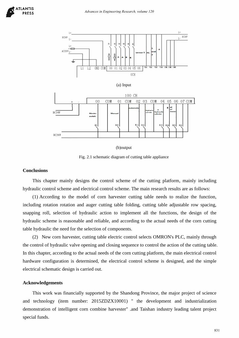
(a) Input
(b)output
Fig. 2.1 schematic diagram of cutting table appliance
Conclusions
This chapter mainly designs the control scheme of the cutting platform, mainly including hydraulic control scheme and electrical control scheme. The main research results are as follows:
(1) According to the model of corn harvester cutting table needs to realize the function, including rotation rotation and auger cutting table folding, cutting table adjustable row spacing, snapping roll, selection of hydraulic action to implement all the functions, the design of the hydraulic scheme is reasonable and reliable, and according to the actual needs of the corn cutting table hydraulic the need for the selection of components.
(2) New corn harvester, cutting table electric control selects OMRON's PLC, mainly through the control of hydraulic valve opening and closing sequence to control the action of the cutting table. In this chapter, according to the actual needs of the corn cutting platform, the main electrical control hardware configuration is determined, the electrical control scheme is designed, and the simple electrical schematic design is carried out.
Acknowledgements
This work was financially supported by the Shandong Province, the major project of science and technology (item number: 2015ZDZX10001) " the development and industrialization demonstration of intelligent corn combine harvester" .and Taishan industry leading talent project special funds.
Advances in Engineering Research, volume 120
831

References
[1] Miu P I, Heinz D K. Simulation of threshing and separation processes in threshing units[J]. Agrartechnische Forschung Sonderheft,2000,(6):1-7.
[2] Miu P I. Mathematical model of material kinematics in an axial threshing unit[J].Computers and Electronics in Agriculture,2007,58(2):93-99.
[3] Miu P I. Mathematical model of threshing process in an axial unit with tangential feeding[J].CSAE. 2002,(2):212-219.
[4] Marchant J A. Tracking of row structure in three crops using image analysis.Comput Electron Agr.1996.15(2):161-179.
[5] Jose A. J. Berni, J. Zarco-Tejada, Lola Suárez, et al. Thermal and Narrowband Multispectral Remote Sensing for Vegetation Monitoring From an Unmanned Aerial Vehicle [J].Transactions on Geoscience and Remote Sensing,2009,47(3):722-738.
Advances in Engineering Research, volume 120
832