Embed Size (px)
Citation preview
Turk J Elec Eng & Comp Sci
(2016) 24: 4497 – 4507
c⃝ TUBITAK
doi:10.3906/elk-1505-78
Turkish Journal of Electrical Engineering & Computer Sciences
http :// journa l s . tub i tak .gov . t r/e lektr ik/
Research Article
Some observations on no-load losses of an asymmetrical six-phase synchronous
machine
Arif IQBAL∗, Girish Kumar SINGH, Vinay PANTDepartment of Electrical Engineering, Indian Institute of Technology Roorkee, Roorkee, Uttarakhand, India
Received: 08.05.2015 • Accepted/Published Online: 11.08.2015 • Final Version: 20.06.2016
Abstract: The use of multiphase (more than three-phase) ac machines is well adopted in different high power applications
and the evaluation of different losses (no load losses, short circuit load loss, friction and windage losses, and stray loss) in
multiphase machines is extremely important for the correct determination of their operating performance. Therefore, the
paper presents a detailed experimental investigation of an asymmetrical (30◦ displacement between the two winding sets)
six-phase synchronous machine for determination of different losses under no-load condition. Moreover, a comparative
study of losses for a six-phase and three-phase synchronous machine has also been performed. The results are presented
for different synchronous speeds (associated with frequency range 30–55 Hz).
Key words: Six-phase synchronous machine, no-load losses, multiphase machine
1. Introduction
The use of multiphase machines (both induction and synchronous) has been well adopted in various applications,
because of several potential inherent advantages when compared with their three-phase counterpart. The
important advantages are as follows [1–4]: reduction in torque pulsation, increased power handling capability,
reduced per phase current without increase in voltage level, higher reliability etc.
Performance of any electrical machine, whether it is dc or ac (single phase, three-phase, or more than
three-phase) is directly affected by the inherent presence of different losses (no load losses, short circuit
load loss, friction and windage losses, and stray loss). In order to determine the accurate performance of
electrical machines, determination of different losses is extremely important. A number of studies in the
literature evaluated different losses of three-phase machines (both induction and synchronous), with standard
test procedures [5,6]. References [7–10] deal with the losses in a six-phase induction machine and its comparison
with its three-phase counterpart. However, no reference related to the detection of losses in a six-phase
synchronous machine is available. Therefore, the main contribution of this paper is to present an experimental
investigation for the determination of various losses under no-load condition in a six-phase synchronous machine.
A comparative study of losses for a six- and three-phase synchronous machine has also been conducted.
2. Description of experimental setup
In order to evaluate the different losses, a 3.2-kW, 36-slot, 6-pole, 3-phase synchronous machine was used. On its
terminal box, the end terminals of the stator winding coils were connected to realize the different winding scheme
∗Correspondence: [email protected]
4497

IQBAL et al./Turk J Elec Eng & Comp Sci
for different numbers of phases and poles. Six-phase winding was obtained by using the technique of phase belt
split [1,4] in a three-phase synchronous machine. The winding configuration of six phases was asymmetrical
in nature, because of the existence of 30◦ electrical phase shift between the winding sets abc and xyz, having
separate neutral points. Hence, fault propagation between the winding sets abc and xyz is prevented together
with the prevention of flow of the third and its multiple harmonic current. Since the dc excitation system is an
essential part of a synchronous machine, in the considered analytical and test system the synchronous alternator
and excitation generator have been considered as a single entity. In the experimental setup, a 5-kW, 250-V,
21.6-A, 1372/1750-rpm dc machine (as motor) was mechanically coupled to the test machine. Measurement and
recording of different experimental readings were carried out by using several analogue ammeters and voltmeters,
together with the use of a power quality analyzer (Hioki 3197). A general view of the experimental setup is
shown in Figure 1.
Exciter generator
DC supply
DC motor
Tachometer
Rheostat
Test synchronous machine
Figure 1. Experimental prototype showing complete setup.
3. Evaluation of fixed losses of DC machine
Initially, both machines (synchronous machine and dc machine) were mechanically uncoupled. The dc motor
was run at the synchronous speed of the test machine, and current and voltage were recorded. Power input
minus copper loss will give the iron loss, friction, and windage loss of the dc machine as given by
L1 = VaIa − I2aRa, (1)
where Va and Ia are the input dc voltage and current fed to the dc motor, having its armature resistance Ra .
It is worthwhile to note here that the iron loss of the dc machine is dependent on both rotor speed and field
current. At a constant speed, it becomes dependent on the flow of field current only. Therefore, at constant rotor
speed, fixed losses, L1 , can be plotted as the function of motor field current, If . The results are presented in
Figure 2, wherein the effects of both field current and rotor speed are shown. A series of experimental recording
has been made at different speeds, i.e. at 600, 700, 800, 900, 1000, 1100 rpm (synchronous speed of 30, 35, 40,
45, 50, 55 Hz). Almost linear dependency of fixed losses may be noted not only on the motor field current but
also on its rotor speed.
4. Determination of friction and windage losses
The test synchronous machine (acting as alternator) and its prime mover (i.e. dc motor) are mechanically
coupled. The coupled machines are run at the synchronous speed with the field circuit of the test synchronous
4498

IQBAL et al./Turk J Elec Eng & Comp Sci
(a) (b)
(c) (d)
(e) (f)
150
200
250
300
350
0.3 0.5 0.7 0.9 1.1
Fix
ed l
oss
es (
W)
Field current (A)
At 1100 rpm.
150
170
190
210
230
250
270
290
310
330
0.4 0.6 0.8 1 1.2
Fix
ed l
oss
es (
W)
Field current (A)
At 1000 rpm
150
200
250
300
350
0.3 0.5 0.7 0.9 1.1
Fix
ed l
oss
es (
W)
Field current (A)
At 900 rpm
150
200
250
300
350
0.3 0.5 0.7 0.9 1.1F
ixed
lo
sses
(W
)
Field current (A)
At 800 rpm
150
200
250
300
350
0.4 0.6 0.8 1 1.2
Fix
ed l
oss
es (
W)
Field current (A)
At 700 rpm
150
200
250
300
350
0.4 0.5 0.6 0.7 0.8 0.9 1
Fix
ed l
oss
es (
W)
Field current (A)
At 600 rpm
Figure 2. Fixed losses of dc motor at different rotor speed associated with the synchronous speed of (a) 1100 rpm, (b)
1000 rpm, (c) 900 rpm, (d) 800 rpm, (e) 700 rpm, (f) 600 rpm.
alternator remaining unexcited. During this condition, power taken by the dc motor will be equal to its
losses (L1+ armature copper loss) and windage and friction losses of the synchronous alternator (Lfw).
Mathematically,
Lfw = VaIa − I2aRa − L1, (2)
where the value of L1 (iron and friction and windage losses of the dc motor) is evaluated in an earlier section.
This test was repeated for different rotor speeds, corresponding to different operating frequencies of the test
synchronous alternator. An approximately linear dependency of friction and windage losses on rotor speed was
noted, as depicted in Figure 3 by a green bar graph.
5. No-load losses in synchronous machine
DC supply is fed to the prime mover (dc motor) so as to run the alternator at synchronous speed. The field
circuit of the alternator is excited with its armature open circuited. A series of readings was recorded for
alternator generated voltage Voc , dc motor field current If , input voltage Va , and current Ia of the prime
mover armature circuit, associated with different values of alternator field current Ifr . In this test, the input
4499

IQBAL et al./Turk J Elec Eng & Comp Sci
0
50
100
150
200
250
600 700 800 900 1000 1100F
rict
ion a
nd w
indag
e lo
sses
(W
)
Speed (rpm)
6 Phase3 Phase
Section 4
Figure 3. Friction and windage losses of synchronous machine by experiment in section 4 (green bar) and by experiment
in section 5 for 6 phase (blue bar) and 3 phase (red bar).
power to the dc motor (VaIa) basically accounts for different losses. These losses include the copper loss of
motor armature circuit I2aRa , fixed losses of dc motor L1 , alternator friction and windage losses Lfw , and its
core losses Lc . Mathematically, it can be expressed as
Lfw + Lc = VaIa −(L1 + I2aRa
). (3)
It will be convenient to determine the value of (Lfw+Lc) graphically, with the variation in alternator generated
voltage/field current. A series of experimental tests has been carried out on the test synchronous alternator
having its winding configuration of both six phase as well as three phase, and the results are depicted in Figure
4. In general, the magnitude of no-load losses increases with the increase in generated open circuit voltage or
field excitation current of the synchronous alternator at a particular rotor speed. Further, the magnitude of
no-load losses increases with the increase in rotor speed, showing its dependency on the operating frequency.
This magnitude was higher for the test synchronous alternator with its six-phase winding configuration. It is
worthwhile to mention here that the y -intercept in Figure 4 determines the magnitude of friction and windage
losses (Lfw) of the test synchronous alternator, which are also shown in Figure 3. Friction and windage losses
were found to be dependent not only on its operating rotor speed but also on the type of armature winding
configuration (six- or three-phase stator winding of the test machine). In general, the value of Lfw is higher
for the six-phase winding configuration when compared with its three-phase winding configuration of the test
alternator. In addition to friction and windage losses, the major component of no-load losses is constituted by
the core loss. This loss is inherently present in all electrical machines, dependent on the type of core material
used, operating frequency, and flux level. The core loss consists of eddy current loss and hysteresis loss. A
convenient way for the evaluation of these losses is discussed in the following section.
5.1. Separate evaluation of eddy and hysteresis losses
The component of machine core loss, i.e. eddy current loss (Lce) and hysteresis loss (Lch), are expressed as
Lc = Lce + Lch (4)
Lce = Kef2B2
m
Lch = KhfBnm, (5)
where Ke = a constant, whose value depends on the type of ferromagnetic material used, lamination thickness,
and volume of core material.
4500

IQBAL et al./Turk J Elec Eng & Comp Sci
(a) (b)
(c) (d)
0
100
200
300
400
500
600
700
0 50 100 150 200 250 300
No l
oad
loss
es (
W)
Open circuit voltage (v)
3 phase 6 phase
At 55 Hz
0
100
200
300
400
500
600
0 50 100 150 200 250
No l
oad
loss
es (
W)
Open circuit voltage (V)
3 phase 6 phase
At 50 Hz
0
100
200
300
400
500
0 50 100 150 200
No l
oad
loss
es (
W)
Open circuit voltage (V)
3 phase 6 phase
At 45 Hz
0
100
200
300
400
0 50 100 150
No l
oad
loss
es (
W)
Open circuit voltage (V)
3 phase 6 phase
At 40 Hz
(e) (f)
0
50
100
150
200
250
300
350
400
0 50 100 150
No l
oad
loss
es (
W)
Open circuit voltage (V)
3 phase 6 phase
At 35Hz
0
50
100
150
200
250
300
0 20 40 60 80
No l
oad
loss
es (
W)
Open circuit Voltage (V)
3 phase 6 phase
At 30Hz
Figure 4. Experimental results of no-load loss of synchronous machine in 3-phase and 6-phase winding configuration at
different synchronous speeds: (a) 55 Hz, (b) 50 Hz, (c) 45 Hz, (d) 40 Hz, (e) 35 Hz, (f) 30 Hz.
Kh = a constant, whose value depends on core weight.
Bm = maximum value of flux density. n denotes the Steinmetz constant, whose value varies from 1.5 to
2.5, depending on the magnetic properties of the core material.
Hence, eddy current loss varies with the squared value of frequency and hysteresis loss becomes propor-
tional to the operating frequency at a fixed value of flux density (i.e. flux linkage of synchronous machine).
Therefore, it will be convenient to rewrite Eq. (5) as
Lce = Cef2(eddy current loss)
Lch = Chf(hysteresis loss).(6)
The values of constants Ce and Ch are determined experimentally for a fixed flux density. In this experiment,
4501
IQBAL et al./Turk J Elec Eng & Comp Sci
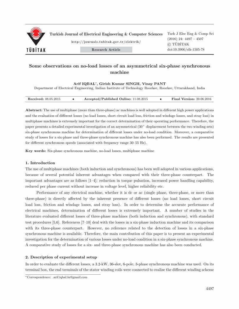
the magnitude of test machine flux linkage is kept constant by just keeping the value of field excitation current
at a fixed value. This is because the machine is operating at no-load condition with no-armature reaction,
and flux linkage is determined by the field circuit only. Therefore, the field current of the alternator is kept
constant at some suitable value, say 0.6 A, and a series of experimental data was recorded for different rotor
speeds (synchronous speed corresponding to 30, 35, 40, 45, 50, 55 Hz). The results obtained are depicted in
Figure 5 for both six-phase and three-phase winding configuration. In this figure, the expression for losses has
been determined by curve fitting [11,12]. The constant term indicates the friction and windage losses; the first
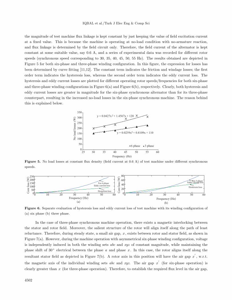
order term indicates the hysteresis loss, whereas the second order term indicates the eddy current loss. The
hysteresis and eddy current losses are plotted for different operating rotor speeds/frequencies for both six-phase
and three-phase winding configurations in Figure 6(a) and Figure 6(b), respectively. Clearly, both hysteresis and
eddy current losses are greater in magnitude for the six-phase synchronous alternator than for its three-phase
counterpart, resulting in the increased no-load losses in the six-phase synchronous machine. The reason behind
this is explained below.
y = 0.0427x 2 + 1.4567x + 120
y = 0.0259x2 + 0.8109x + 110
0
50
100
150
200
250
300
350
25 30 35 40 45 50 55 60
No l
oad
loss
es (
W)
Frequency (Hz)
6 phase 3 phase
Figure 5. No load losses at constant flux density (field current at 0.6 A) of test machine under different synchronous
speeds.
0 10 20 30 40 50 600
20
40
60
80
Frequency (Hz)
(b)
Co
re lo
ss (
W)
0 10 20 30 40 50 60050
100150200250
Frequency (Hz)
(a)
Co
re lo
ss (
W)
Hesteresis loss
For 6 phaseFor 3 phase
Eddy current loss
Hesteresis loss
Eddy current loss
Figure 6. Separate evaluation of hysteresis loss and eddy current loss of test machine with its winding configuration of
(a) six phase (b) three phase.
In the case of three-phase synchronous machine operation, there exists a magnetic interlocking between
the stator and rotor field. Moreover, the salient structure of the rotor will align itself along the path of least
reluctance. Therefore, during steady state, a small air gap, x , exists between rotor and stator field, as shown in
Figure 7(a). However, during the machine operation with asymmetrical six-phase winding configuration, voltage
is independently induced in both the winding sets abc and xyz of constant magnitude, while maintaining the
phase shift of 30◦ electrical between the phase a and phase x . In this case, the rotor aligns itself along the
resultant stator field as depicted in Figure 7(b). A rotor axis in this position will have the air gap x′, w.r.t.
the magnetic axis of the individual winding sets abc and xyz. The air gap x′(for six-phase operation) is
clearly greater than x (for three-phase operation). Therefore, to establish the required flux level in the air gap,
4502

IQBAL et al./Turk J Elec Eng & Comp Sci
magnetizing current (i.e. field current Ifr in the present case) is increased, resulting in increased no-load losses
in the test machine having asymmetrical six-phase winding configuration. Furthermore, in the machine with
constant field excitation at no-load, flux linkage to stator winding with the three-phase configuration will be
greater than its operation with six-phase winding configuration, because x, > x . Hence, voltage generation in
the six-phase machine will be somewhat less than half the generated voltage (theoretically it should be exactly
half) in armature winding in the three-phase configuration with increased no-load losses with the six-phase
winding configuration.
ξ
N N1 N2
S S
xx,
(a) (b)
Figure 7. Effective air gap distance in machine operation for (a) three-phase operation and (b) six-phase operation.
6. Determination of short circuit (SC) load test
The rotor speed is maintained constant at synchronous speed from the prime mover side and the end terminals
of the alternator stator winding is shorted (symmetrical SC). It should be noted that in the case of an alternator
with the six-phase winding configuration, each three-phase set (abc and xyz ) is shorted separately. The power
consumed by the dc motor (VaIa) will be equal to the sum of losses L1 + I2aRa + Lfw , together with the
alternator load losses corresponding to the stator SC current. Hence, SC load loss can be easily evaluated by
knowing the value of other losses from experiments 1, 2, and 3. Mathematically,
SC load loss = VaIa − (L1 + I2aRa + Lfw) (7)
Further, stray load loss may be evaluated if the dc resistance of alternator stator winding r1 (and r2) is known,
by using Eq. (8).
Stray load loss = (SCloadloss)− (armature dc copper loss I2s1r1 + I2s2r2), (8)
where Is1 , Is2 and r1 , r2 are the stator phase current and dc resistance of both winding sets abc and xyz,
respectively.
These experimental steps have been carried out for both six-phase and three-phase stator winding
configuration at different rotor speeds. At a particular stator winding configuration, the SC loss magnitude was
found to be dependent on the flow of stator current only and not much affected by rotor speed for particular
field excitation. This is depicted in Figure 8, wherein the dependency of SC loss on the squared value of stator
current is signified by the straight line. The SC load loss comprises the armature copper loss, core loss due
4503

IQBAL et al./Turk J Elec Eng & Comp Sci
to armature leakage flux, and a small core loss due to resultant flux. Magnitude of the stator current is much
larger in the six-phase winding configuration than in its three-phase counterpart. However, the magnitude of
total armature copper is almost the same for both six-phase and three-phase winding. In the case of six-phase
operation, on the other hand, magnitude of leakage flux and also the resultant flux are increased. The increased
magnitude of flux linkage results in higher magnitude of core loss. Therefore, the magnitude of SC loss was
found to be higher with the six-phase stator winding configuration than with its three-phase counterpart. By
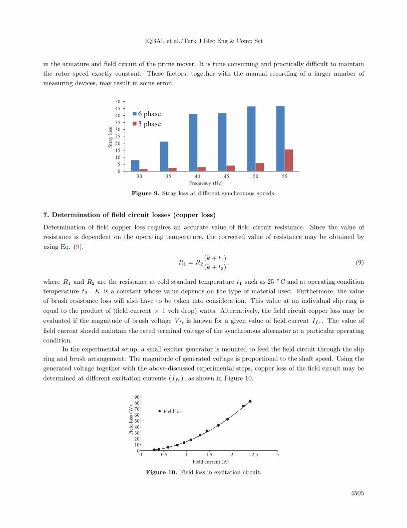
utilizing the evaluated values of SC loss, Eq. (8) was used to find the alternator stray loss. This is expressed
for stator current of 2 A at different rotor speeds for both six-phase and three-phase winding configuration as
shown in Figure 9. Stray loss was also found to be greater for the six-phase winding configuration than for its
three-phase counterpart.
(a) (b)
(d)(c)
(e) (f)
0
200
400
600
800
0 5 10 15
SC l
oss
(W
)
3 phase 6 phase
At 55 Hz
0
100
200
300
400
500
600
0 2 4 6 8 10
SC l
oss
(W
)
3 phase 6 phase
At 50 Hz
0
100
200
300
400
500
0 2 4 6 8
SC l
oss
(W
)
3 phase 6 phase
At 45 Hz
0
50
100
150
200
250
300
350
400
0 1 2 3 4 5
SC l
oss
(W
)
3 phase 6 phase
At 40 Hz
0
50
100
150
200
250
300
350
0 1 2 3
SC l
oss
(W
)
3 phase 6 phase
At 35 Hz
0
50
100
150
200
0 0.5 1 1.5 2
SC l
oss
(W
)
Squared current (A2) Squared current (A2)
Squared current (A2) Squared current (A2)
Squared current (A2) Squared current (A2)
3 phase 6 phase
At 30 Hz
Figure 8. Short circuit loss of test synchronous machine at different rotor speeds.
During the process of loss determination, the existence of its small irregular trend may also be noted.
This is because of continuous variation in loads connected to the utility grid, resulting in change in input (dc
through rectifier) voltage. During the experiment, rotor speed was also controlled manually by using a rheostat
4504
IQBAL et al./Turk J Elec Eng & Comp Sci
in the armature and field circuit of the prime mover. It is time consuming and practically difficult to maintain
the rotor speed exactly constant. These factors, together with the manual recording of a larger number of
measuring devices, may result in some error.
0
5
10
15
20
25
30
35
40
45
50
30 35 40 45 50 55
Str
ay l
oss
Frequency (Hz)
6 phase
3 phase
Figure 9. Stray loss at different synchronous speeds.
7. Determination of field circuit losses (copper loss)
Determination of field copper loss requires an accurate value of field circuit resistance. Since the value of
resistance is dependent on the operating temperature, the corrected value of resistance may be obtained by
using Eq. (9).
R1 = R2(k + t1)
(k + t2), (9)
where R1 and R2 are the resistance at cold standard temperature t1 such as 25 ◦C and at operating condition
temperature t2 . K is a constant whose value depends on the type of material used. Furthermore, the value
of brush resistance loss will also have to be taken into consideration. This value at an individual slip ring is
equal to the product of (field current × 1 volt drop) watts. Alternatively, the field circuit copper loss may be
evaluated if the magnitude of brush voltage Vfr is known for a given value of field current Ifr . The value of
field current should maintain the rated terminal voltage of the synchronous alternator at a particular operating
condition.
In the experimental setup, a small exciter generator is mounted to feed the field circuit through the slip
ring and brush arrangement. The magnitude of generated voltage is proportional to the shaft speed. Using the
generated voltage together with the above-discussed experimental steps, copper loss of the field circuit may be
determined at different excitation currents (Ifr), as shown in Figure 10.
0
10
20
30
40
50
60
70
80
90
0 0.5 1 1.5 2 2.5 3
Fie
ld l
oss
(W
)
Field current (A)
Field loss
Figure 10. Field loss in excitation circuit.
4505

IQBAL et al./Turk J Elec Eng & Comp Sci
8. Conclusion
This paper presents a detailed experimental evaluation of different losses of a six-phase synchronous machine.
Results have been presented for different rotor synchronous speeds (at frequency of 30, 35, 40, 45, 50, 55 Hz).
In general, the different no-load losses of the synchronous machine with six-phase winding configuration were
found to be greater than those of its three-phase counterpart. Some of the important concluding remarks may
be listed as follows:
(a) Friction and windage losses were a linear function of rotor speed.
(b) No-load losses of the test synchronous machine were dependent on both field voltage/current and rotor
speed. At a particular excitation, the difference in no-load losses for the machines with six-phase and
three-phase winding configuration increases linearly with rotor synchronous speed. Furthermore, increased
no-load loss (resulting in increased core loss) for the six-phase operation is due to the increased effective
air gap x, between the rotor and stator magnetic axis of individual winding sets (abc and xyz ).
(c) In the six-phase test machine, the magnitude of short circuit loss is higher than that of its three-phase
counterpart. This is mainly because of the increased magnitude of resultant flux, thereby increasing the
value of local core losses.
(d) Losses in the field circuit are dependent on the magnitude of its excitation current. These losses are
independent of the rotor speed at a particular excitation current. Losses in the field circuit were found to
be proportional to the squared value of excitation current.
The different no-load loss components of the synchronous machine with the six-phase winding configuration
were greater than those of its three-phase counterpart. However, during load condition, the per phase
current in the six-phase winding configuration is substantially reduced for a given load. Further, the
asymmetrical six-phase winding configuration with displacement angle of 30◦ electrical results in the
elimination of all the air gap flux harmonics of order (6x ± 1;x = 1, 3, 5 . . .). This leads to a substantial
decrease in losses (particularly stray loss) and overall improved performance of the six-phase synchronous
machine as compared to its three-phase counterpart.
References
[1] Singh GK. Multiphase induction machine drive research - a survey. Elect Pow Syst Res 2002; 61: 139-147.
[2] Levi E. Multiphase electric machines for variable-speed applications. IEEE T Ind Electron 2008; 55: 1893-1909.
[3] Singh GK. Modeling and analysis of six-phase synchronous generator for stand-alone renewable energy generation.
Energy 2011; 36: 5621-5631.
[4] Klingshrin EA. High phase order induction motor - part-I: description and theoretical consideration. IEEE T Power
Ap Syst 1983; 102: 47-53.
[5] Kohli DR, Jain SK. A Laboratory Course in Electrical Machines. 2nd edition, India: JBA Publisher, 2000, pp.
300-307.
[6] The Institute of Electrical and Electronics Engineers Inc. 1995 IEEE Guide: Test Procedures for Synchronous
Machines (IEEE Std 115-1995).
[7] Klingshrin EA. High phase order induction motor - part-II: experimental results. IEEE T Power Ap Syst 1983; 102:
54-59.
4506

IQBAL et al./Turk J Elec Eng & Comp Sci
[8] Boglietti A, Bojoi R, Cavagnino A, Tenconi A. Efficiency analysis of PWM inverter fed three-phase and dual three-
phase high frequency induction machines for low/medium power applications. IEEE T Ind Electron; 2008: 55:
2015-2023.
[9] Dorrell DG, Leong CY, McMahon RA. Performance assessment of six-pulse inverter-fed three phase and six phase
induction machine. IEEE T Ind Appl 2006; 42: 1487-1495.
[10] Singh GK. A six-phase synchronous generator for stand-alone renewable energy generation: experimental analysis.
Energy 2011; 36: 1768-1775.
[11] Lancaster P, Salkauskas K. Curve and Surface Fitting: An Introduction. San Diego, CA, USA: Academic Press,
1990.
[12] Guest PG. Numerical Method of Curve Fitting. New York, NY, USA: Cambridge University Press, 2013.
4507