Embed Size (px)
Citation preview


ELEC
TRONIC
SOLUTI
ONS
3
1
4
2
5
ACCE
SS
CONTR
OL
ELEC
TRON
IC
LOCK
S
EMER
GENCY
EXITCO
NTROLS
FIRE D
OOR
CONT
ROLS
AND F
IRE
PREV
ENTIO
N
ELEC
TRIC
LOCK
S


2-1
Electroniclocks
THESIS 2.0
Top Exit DGT
x1R
Iseo electronic locks combine the featu-res functionalities of high security mecha-nical locks with the electronic manage-ment in order to increase door security and comfort for end users.
Thanks to motors or electromagnets, the electronic control allows automate locks’ opening and/or closing movements. Thus the security of the door is guaranteed in any situation.
The sensors within the locks allow to in-tegrate them in monitoring and building management systems.
our range of electronic locks includes dif-ferent models, meets any installation and functionality needs and suits to any types of doors.
Iseo electronic locks have been conceived and manufactured according to european standards and have obtained different pro-duct certifications in order to meet specific national and international legal require-ments.
The electronic locks are supplied with Lockbus interface, can be integrated in any Iseo access control system and don’t require any further interface modules. The-refore the installation and the communica-tion security have been optimized.
Electroniclocks
2-3
C
C
8
8
0
0
0
0
G
G
3
3
0
1
1
1
3
3*
StandardThesis 2.0
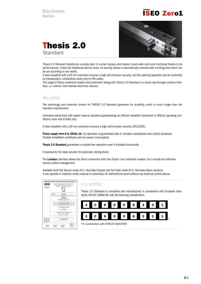
The technology and materials chosen for THESIS 2.0 Standard guarantee its durability, which is much longer than the standard requirements.
Innovative electronics with power reserve (booster) guaranteeing an efficient deadbolt movement in difficult operating con-ditions: even with 8 Volts only.
A steel deadbolt with a 20 mm extension ensures a high anti-intrusion security (EN12209).
Power supply from 8 to 30Vdc 1A. Its operation is guaranteed also in complex installations and critical situations.Flexible installation conditions and low power consumption.
Thesis 2.0 Standard guarantees a trouble-free operation even if installed horizontally.
It represents the ideal solution for automatic sliding doors.
The Lockbus interface allows the direct connection with Iseo Stylos Line credential readers, for a simple but effectiveaccess control management.
Available both Fail Secure mode (N.C. Normally Closed) and Fail Safe mode (N.O. Normally Open) versions.It can operate in interlock mode (manual or automatic) for bidirectional doors without any external control device.
Thesis 2.0 Standard transforms a simple door in a smart access and makes it even safer and more functional thanks to its performances. Unlike the traditional electric locks, its security status is automatically restored with a locking time which can be set according to any needs. A steel deadbolt with a 20 mm extension ensures a high anti-intrusion security, and the opening operation can be controlled by transponders, contactless cards and/or PIN codes.The range of Stylos credential readers and controllers dialog with Thesis 2.0 Standard in a direct way through Lockbus inter-face, i.e. without intermediate electronic devices.
It is certified
Thesis 2.0 Standard is conceived and manufactured in compliance with European stan-dards UNI EN 14846:08, with the following classification:
*in combination with STATUS INDICATOR
Key points
Electroniclocks

2-4
THESIS 2.0 Standard
Electroniclocks
Backset: 25/30/35 mm
Deadbolt: - hardened inox steel;- cutting resistant (free rotating); - Ø14 mm diameter; - single throw; - 20 mm extension. European profile cylinder hole. Handle follower (optional): 8 mm; Centre distance between handle follower and cylinder: 85 mm Front plate: - inox steel; - 25x371 mm – thickness 3 mm; - door positioning sensor and alignment device. Striking plate: - Inox steel; - 25x330 mm – thickness 3 mm; - adjustable depending on the distance between the lock and the striking plate;
Case dimensions:- thickness 22 mm- length 280 mm- depth 38/43/48 mm
DC supply voltage range: 8÷30Vdc. Max. absorbed current power in operation: 1A. CC power supply min. characteristics: 8÷30Vdc15W. Opening control: - opto-isolated input 8÷24Vdc/12Vac; Max voltage and current applicable to signalling relay: - 24Vdc 1A; - 120Vac 0.5A.
Programmable status signal: - secured door status;- door status; - bolt status;- command for motorized door opener. Lockbus connection: - data communication and power supply on the same 3 wire connections; - maximum length 100 mt; - secure devices authentification; - encrypted data transmission for high security against hacking. Adjustable timings: - door opening time (courtesy time): 1÷180 sec. (15 sec. default); - delayed closure time (at closing of the door): 1÷60 sec. (1 sec. default).
Technical features

2-5
THESIS 2.0 Standard
Electroniclocks
Environmental features: - operating temperature: -20°C÷+60°C; - storage temperature: -25°C÷+70°C; - protection level (IP grading): IP44;Reference Standard: UNI EN 14846:2008; grading: 3 C 8 0 0 G 3 0 1 3 C 8 0 0 G 3 1 1 (in combination with STATUS INDICATOR).
Options and Versions: With and without handle follower Operating modes in case of power failure: - Fail Secure mode (N.C. Normally Closed) - Fail Safe mode (N.O. Normally Open) Operating software: - single door;- bidirectional doors with manual interlock functionality (*);- bidirectional doors with automatic interlock functionality (*); (*) direct connection between the 2 lock with encrypted communication.
LoCAL buS
All devices belonging of the THESIS range are compatible with ISEO Lockbus.
Lockbus is a powerful multypeint bus sharing data transmission and power supply on the same 3-wire connection for utmost flexibi-lity, easy installation and consequently, cost optimization.
Lockbus highlights: Data transmission and power supply on the same 3-wire connection up to 100 m;
Self-adjusting power supply from 8Vdc to 30Vdc;
Secure device authentication (among readers and actuators) and encrypteddata transmission for high security against manipulation.
Lockbus
2-6
THESIS 2.0 Standard
6 6
7 7
8
5
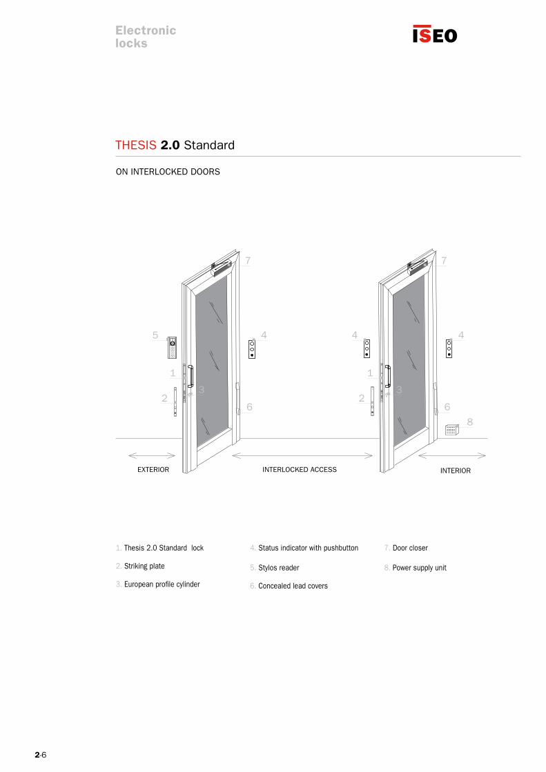
ON INTERLOCKED DOORS
1. Thesis 2.0 Standard lock
2. Striking plate
3. European profile cylinder
4. Status indicator with pushbutton
5. Stylos reader
6. Concealed lead covers
7. Door closer
8. Power supply unit
ExTERIOR INTERLOCKED ACCESS INTERIOR
Electroniclocks

2-7
THESIS 2.0 Standard
6
7
8
5
ExTERIOR INTERIOR
ON SINGLE DOORS
Electroniclocks
1. Thesis 2.0 Standard lock
2. Striking plate
3. European profile cylinder
4. Status indicator with pushbutton
5. Stylos reader
6. Concealed lead covers
7. Door closer
8. Power supply unit

2-8
THESIS 2.0 Standard
07500802521
0750M802521
0750A802521
07500803021
0750M803021
0750A803021
07500803521
0750M803521
0750A803521
1
1
1
1
1
1
1
1
1
DROPBOLT FAIL SECURE WITH HANDLE FOLLOWER. Hardened steel bolt, Ø14 mm diameter, one throw, 20 mm excursion. Stainless steel front plate with alignment device.Stainless steel striking plate with alignment device and in lineframe sensor. Handle follower 8 mm. European profile cylinder hole. Fail Secure mode. Package: 1 dropbolt, 1 striking plate, instruction manual, screws, connector with rubber protection, handle follower.
Handle follower/cylinder centre distance 85 mm
Single door software. Backset 25 mm.
Manual interlock software. Backset 25 mm.
Manual interlock software. Backset 30 mm.
Manual interlock software. Backset 35 mm.
Automatic interlock software. Backset 25 mm.
Single door software. Backset 30 mm.
Automatic interlock software. Backset 30 mm.
Single door software. Backset 35 mm.
Automatic interlock software. Backset 35 mm.
Electroniclocks
Package
Code
2-9
THESIS 2.0 Standard
07500802522
0750M802522
0750A802522
07500803022
0750M803022
0750A803022
07500803522
0750M803522
0750A803522
1
1
1
1
1
1
1
1
1
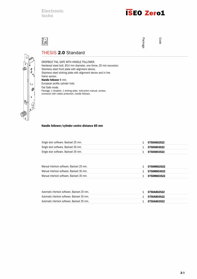
DROPBOLT FAIL SAFE WITH HANDLE FOLLOWER. Hardened steel bolt, Ø14 mm diameter, one throw, 20 mm excursion. Stainless steel front plate with alignment device.Stainless steel striking plate with alignment device and in lineframe sensor. Handle follower 8 mm. European profile cylinder hole. Fail Safe mode. Package: 1 dropbolt, 1 striking plate, instruction manual, screws, connector with rubber protection, handle follower.
Handle follower/cylinder centre distance 85 mm
Single door software. Backset 25 mm.
Manual interlock software. Backset 25 mm.
Manual interlock software. Backset 30 mm.
Manual interlock software. Backset 35 mm.
Automatic interlock software. Backset 25 mm.
Single door software. Backset 30 mm.
Automatic interlock software. Backset 30 mm.
Single door software. Backset 35 mm.
Automatic interlock software. Backset 35 mm.
Electroniclocks
Package
Code
2-10
THESIS 2.0 Standard
07500002521
0750M002521
0750A002521
07500003021
0750M003021
0750A003021
07500003521
0750M003521
0750A003521
1
1
1
1
1
1
1
1
1
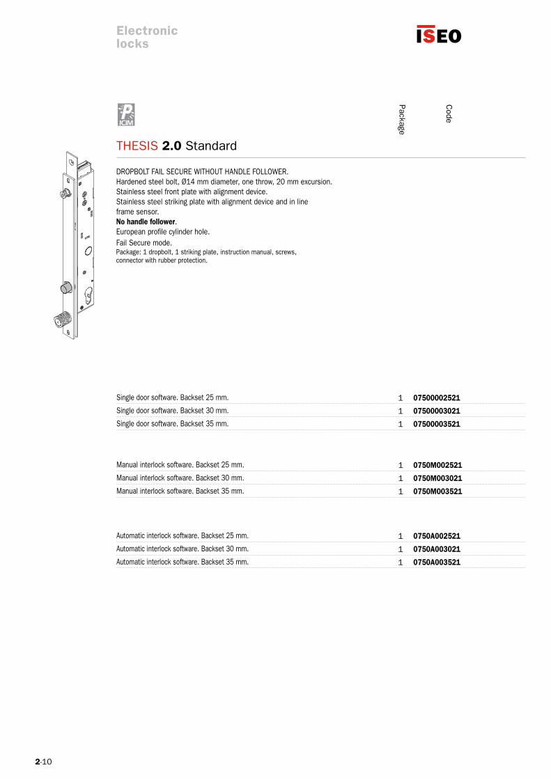
DROPBOLT FAIL SECURE WITHOUT HANDLE FOLLOWER. Hardened steel bolt, Ø14 mm diameter, one throw, 20 mm excursion. Stainless steel front plate with alignment device.Stainless steel striking plate with alignment device and in lineframe sensor. No handle follower. European profile cylinder hole.Fail Secure mode. Package: 1 dropbolt, 1 striking plate, instruction manual, screws,connector with rubber protection.
Single door software. Backset 25 mm.
Manual interlock software. Backset 25 mm.
Manual interlock software. Backset 30 mm.
Manual interlock software. Backset 35 mm.
Automatic interlock software. Backset 25 mm.
Single door software. Backset 30 mm.
Automatic interlock software. Backset 30 mm.
Single door software. Backset 35 mm.
Automatic interlock software. Backset 35 mm.
Electroniclocks
Package
Code

2-11
THESIS 2.0 Standard
07500002522
0750M002522
0750A002522
07500003022
0750M003022
0750A003022
07500003522
0750M003522
0750A003522
1
1
1
1
1
1
1
1
1
DROPBOLT FAIL SAFE WITHOUT HANDLE FOLLOWER. Hardened steel bolt, Ø14 mm diameter, one throw, 20 mm excursion. Stainless steel front plate with alignment device.Stainless steel striking plate with alignment device and in lineframe sensor. No handle follower. European profile cylinder hole.Fail Safe mode. Package: 1 dropbolt, 1 striking plate, instruction manual, screws,connector with rubber protection.
Single door software. Backset 25 mm.
Manual interlock software. Backset 25 mm.
Manual interlock software. Backset 30 mm.
Manual interlock software. Backset 35 mm.
Automatic interlock software. Backset 25 mm.
Single door software. Backset 30 mm.
Automatic interlock software. Backset 30 mm.
Single door software. Backset 35 mm.
Automatic interlock software. Backset 35 mm.
Electroniclocks
Package
Code

2-13
Standard Latchbolt
C
C
8
8
0
0
0
0
G
G
3
3
0
1
1
1
3
3(*)
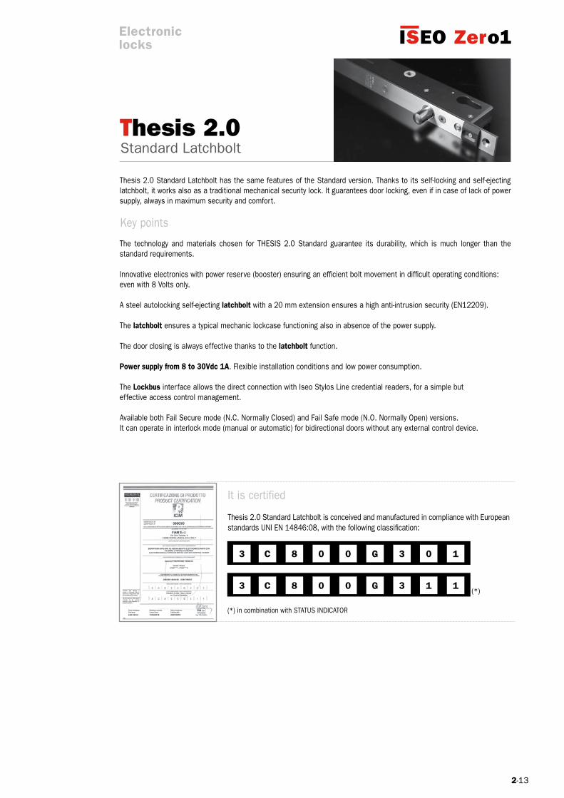
Thesis 2.0
The technology and materials chosen for THESIS 2.0 Standard guarantee its durability, which is much longer than the standard requirements.
Innovative electronics with power reserve (booster) ensuring an efficient bolt movement in difficult operating conditions:even with 8 Volts only. A steel autolocking self-ejecting latchbolt with a 20 mm extension ensures a high anti-intrusion security (EN12209).
The latchbolt ensures a typical mechanic lockcase functioning also in absence of the power supply.
The door closing is always effective thanks to the latchbolt function. Power supply from 8 to 30Vdc 1A. Flexible installation conditions and low power consumption.
The Lockbus interface allows the direct connection with Iseo Stylos Line credential readers, for a simple but effective access control management.
Available both Fail Secure mode (N.C. Normally Closed) and Fail Safe mode (N.O. Normally Open) versions.It can operate in interlock mode (manual or automatic) for bidirectional doors without any external control device.
It is certified
Thesis 2.0 Standard Latchbolt is conceived and manufactured in compliance with European standards UNI EN 14846:08, with the following classification:
(*) in combination with STATUS INDICATOR
Thesis 2.0 Standard Latchbolt has the same features of the Standard version. Thanks to its self-locking and self-ejecting latchbolt, it works also as a traditional mechanical security lock. It guarantees door locking, even if in case of lack of power supply, always in maximum security and comfort.
Key points
Electroniclocks

2-14
THESIS 2.0 Standard Latchbolt
Backset: 25/30/35 mm
Latchbolt: - hardened inox steel; - Ø14 mm diameter; - self-ejecting (mechanical); - 20 mm extension; European profile cylinder hole Handle follower (optional): 8 mm; Centre distance between handle follower and cylinder: 85 mm Front plate: - inox steel; - 25x371 mm – thickness 3 mm; - door positioning sensor and alignment device; Striking plate: - Inox steel; - 25x330 mm – thickness 3 mm; - adjustable depending on the distance between the lock and the striking plate;
Case dimensions:- thickness 22 mm- length 280 mm- depth 38/43/48 mm
DC supply voltage range: 8÷30Vdc. Max. absorbed current power in operation: 1A. CC power supply min. characteristics: 8÷30Vdc 15W. Opening control: - opto-isolated input 8÷24Vdc /12Vac; Max voltage and current applicable to signalling relay: - 24Vdc 1A; - 120Vac 0.5A;
Programmable status signal: - secured door status;- door status; - latchbolt status;- command for motorized door opener; Lockbus connection: - data communication and power supply on the same 3 wire connections; - maximum length 100 mt; - secure devices authentification; - encrypted data transmission for high security against hacking; Adjustable timings: - door opening time (courtesy time): 1÷180 sec. (15 sec. default);
Electroniclocks
Technical features

2-15
THESIS 2.0 Standard Latchbolt
Environmental features: - operating temperature: -20°C÷+60°C; - storage temperature: -25°C÷+70°C; - protection level (IP grading): IP44;
Reference Standard: UNI EN 14846:2008; grading: 3 C 8 0 0 G 3 0 1 3 C 8 0 0 G 3 1 1 (in combination with status indicator)
Options and versions: With and without handle follower Operating modes in case of power failure: Fail Secure mode (N.C. Normally Closed) Operating software: - single door; - bidirectional doors with manual interlock functionality (*); - bidirectional doors with automatic interlock functionality (*); (*) direct connection between the 2 lock with encrypted communication.
LoCAL buS
All devices belonging of the THESIS range are compatible with ISEO Lockbus.
Lockbus is a powerful multypeint bus sharing data transmission and power supply on the same 3-wire connection for utmost flexibility, easy installation and consequently, cost optimization.
Lockbus highlights: Data transmission and power supply on the same 3-wire connection up to 100 m;
Self-adjusting power supply from 8Vdc to 30Vdc;
Secure device authentication (among readers and actuators) and encrypteddata transmission for high security against manipulation.
Lockbus
Electroniclocks

2-16
THESIS 2.0 Standard Latchbolt
6 6
7 7
8
5
Electroniclocks
ON INTERLOCKED DOORS
1. Thesis 2.0 Latchbolt lock
2. Striking plate
3. European profile cylinder
4. Status indicator with pushbutton
5. Stylos reader
6. Concealed lead covers
7. Door closer
8. Power supply unit
ExTERIOR INTERLOCKED ACCESS INTERIOR

2-17
THESIS 2.0 Standard Latchbolt
6
7
8
5
Electroniclocks
ExTERIOR INTERIOR
ON SINGLE DOORS
1. Thesis 2.0 Latchbolt lock
2. Striking plate
3. European profile cylinder
4. Status indicator with pushbutton
5. Stylos reader
6. Concealed lead covers
7. Door closer
8. Power supply unit
2-18
THESIS 2.0 Standard Latchbolt
07510802521
0751M802521
0751A802521
07510803021
0751M803021
0751A803021
07510803521
0751M803521
0751A803521
1
1
1
1
1
1
1
1
1
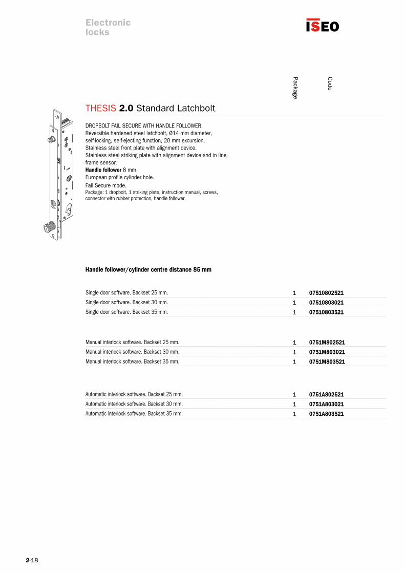
DROPBOLT FAIL SECURE WITH HANDLE FOLLOWER. Reversible hardened steel latchbolt, Ø14 mm diameter,self-locking, self-ejecting function, 20 mm excursion. Stainless steel front plate with alignment device.Stainless steel striking plate with alignment device and in lineframe sensor. Handle follower 8 mm. European profile cylinder hole. Fail Secure mode. Package: 1 dropbolt, 1 striking plate, instruction manual, screws, connector with rubber protection, handle follower.
Handle follower/cylinder centre distance 85 mm
Single door software. Backset 25 mm.
Manual interlock software. Backset 25 mm.
Manual interlock software. Backset 30 mm.
Manual interlock software. Backset 35 mm.
Automatic interlock software. Backset 25 mm.
Single door software. Backset 30 mm.
Automatic interlock software. Backset 30 mm.
Single door software. Backset 35 mm.
Automatic interlock software. Backset 35 mm.
Electroniclocks
Package
Code
2-19
THESIS 2.0 Standard Latchbolt
07510002521
0751M002521
0751A002521
07510003021
0751M003021
0751A003021
07510003521
0751M003521
0751A003521
1
1
1
1
1
1
1
1
1
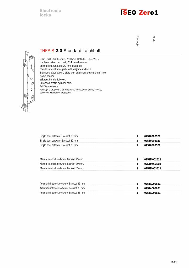
DROPBOLT FAIL SECURE WITHOUT HANDLE FOLLOWER. Hardened steel latchbolt, Ø14 mm diameter,self-ejecting function, 20 mm excursion. Stainless steel front plate with alignment device.Stainless steel striking plate with alignment device and in lineframe sensor. Without handle follower. European profile cylinder hole. Fail Secure mode. Package: 1 dropbolt, 1 striking plate, instruction manual, screws, connector with rubber protection.
Single door software. Backset 25 mm.
Manual interlock software. Backset 25 mm.
Manual interlock software. Backset 30 mm.
Manual interlock software. Backset 35 mm.
Automatic interlock software. Backset 25 mm.
Single door software. Backset 30 mm.
Automatic interlock software. Backset 30 mm.
Single door software. Backset 35 mm.
Automatic interlock software. Backset 35 mm.
Electroniclocks
Package
Code


2-21
ProfessionalThesis 2.0
Electroniclocks
The technology and materials chosen for THESIS 2.0 Professional guarantee its durability, which is much longer than the standard requirements (even over 1 million operating cycles).
A hardened steel deadbolt with a 18 mm diameter, and 22 mm extension and a 4 mm stainless steel front plate ensure a high anti-intrusion security (level 7 ** according to EN12209 standard).
The operation is guaranteed even in case of a residual lateral load up to 15N and of a bad door alignment. This is why it is at the top of the market.
Innovative electronics with power reserve (booster) guaranteeing an efficient deadbolt movement in difficult operating con-ditions: even with 8V only!
Power supply from 8 to 30Vdc 1A. Its operation is guaranteed also in complex installations and critical situations. Flexible installation conditions and low power consumption.
Thesis 2.0 Professional guarantees a trouble-free operation even if installed horizontally. It represents the ideal solution for automatic sliding doors.
The Lockbus interface allows the direct connection with Iseo Stylos Line credential readers, for a simple but effective access control management.
Available both Fail Secure mode (N.C. Normally Closed) and Fail Safe mode (N.O. Normally Open) versions.
It can operate in interlock mode (manual or automatic) for double doors without any external control device.
(**) estimated classification. Test in progress.
Thesis 2.0 Professional is the Heavy Duty version of the Thesis 2.0 Standard. It combines the functions of the standard ver-sion to the soundness and anti-manipulation resistance, which make it the ideal solution for professional installations where maximum passive security and high use frequency are required, such as shops, banks and public offices entrances. Thesis 2.0 transforms a simple door in a smart gate and makes it even safer and more functional because it restores automatically its security status thanks to the delayed time locking to be set directly from the end user according to his different needs. A steel deadbolt with a 22 mm extension ensures a high anti-intrusion security, and the opening operation can be controlled by transponders, contactless cards and/or PIN codes. The range of Stylos credential readers and controllers dialog with Thesis 2.0 Professional in a direct way through Lockbus interface, i.e. without intermediate electronic devices, creating flexible and effective electronic access control solutions.
Key points
2-22
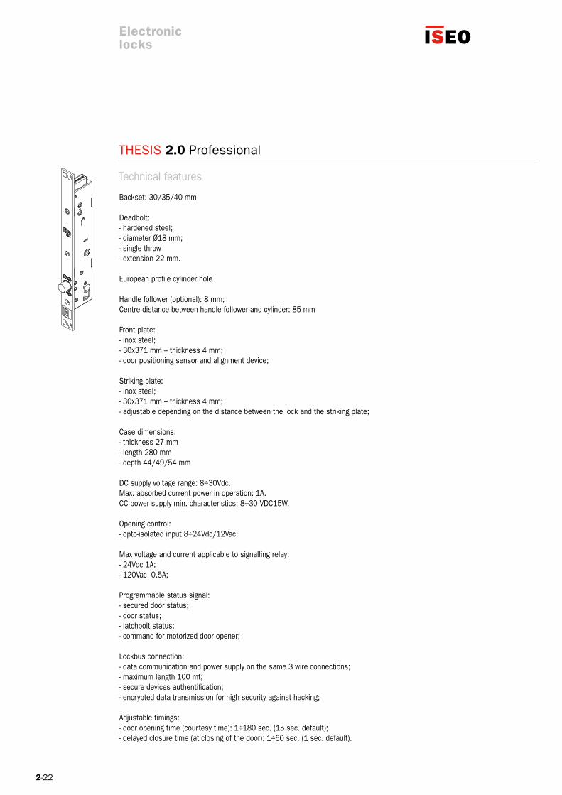
THESIS 2.0 Professional
Backset: 30/35/40 mm
Deadbolt:- hardened steel;- diameter Ø18 mm;- single throw- extension 22 mm. European profile cylinder hole Handle follower (optional): 8 mm; Centre distance between handle follower and cylinder: 85 mm Front plate: - inox steel; - 30x371 mm – thickness 4 mm; - door positioning sensor and alignment device; Striking plate: - Inox steel; - 30x371 mm – thickness 4 mm; - adjustable depending on the distance between the lock and the striking plate;
Case dimensions:- thickness 27 mm- length 280 mm- depth 44/49/54 mm
DC supply voltage range: 8÷30Vdc. Max. absorbed current power in operation: 1A. CC power supply min. characteristics: 8÷30 VDC15W. Opening control: - opto-isolated input 8÷24Vdc/12Vac; Max voltage and current applicable to signalling relay: - 24Vdc 1A; - 120Vac 0.5A;
Programmable status signal: - secured door status;- door status; - latchbolt status;- command for motorized door opener; Lockbus connection: - data communication and power supply on the same 3 wire connections; - maximum length 100 mt; - secure devices authentification; - encrypted data transmission for high security against hacking; Adjustable timings: - door opening time (courtesy time): 1÷180 sec. (15 sec. default);- delayed closure time (at closing of the door): 1÷60 sec. (1 sec. default).
Technical features
Electroniclocks
2-23
THESIS 2.0 Professional
Lockbus
Environmental features: - operating temperature: -20°C÷+60°C; - storage temperature: -25°C÷+70°C; - protection level (IP grading): IP44;
Reference Standard: UNI EN 14846:2008; grading: 3 H 8 0 0 E 7 0 1 (**) 3 H 8 0 0 E 7 0 1 (in combination with status indicator) (**)
Options and versions: With and without handle follower Operating modes in case of power failure: - Fail Secure mode (N.C. Normally Closed) Operating software: - single door; - bidirectional doors with manual interlock functionality (*); - bidirectional doors with automatic interlock functionality (*); (*) direct connection between the 2 lock with encrypted communication. (**) estimated classification. Test in progress.
LoCAL buS
All devices belonging of the THESIS range are compatible with ISEO Lockbus.
Lockbus is a powerful multypeint bus sharing data transmission and power supply on the same 3-wire connection for utmost flexibility, easy installation and consequently, cost optimization.
Lockbus highlights: Data transmission and power supply on the same 3-wire connection up to 100 m;
Self-adjusting power supply from 8Vdc to 30Vdc;
Secure device authentication (among readers and actuators) and encrypteddata transmission for high security against manipulation.
Electroniclocks
2-24
THESIS 2.0 Professional
6 6
7 7
8
5
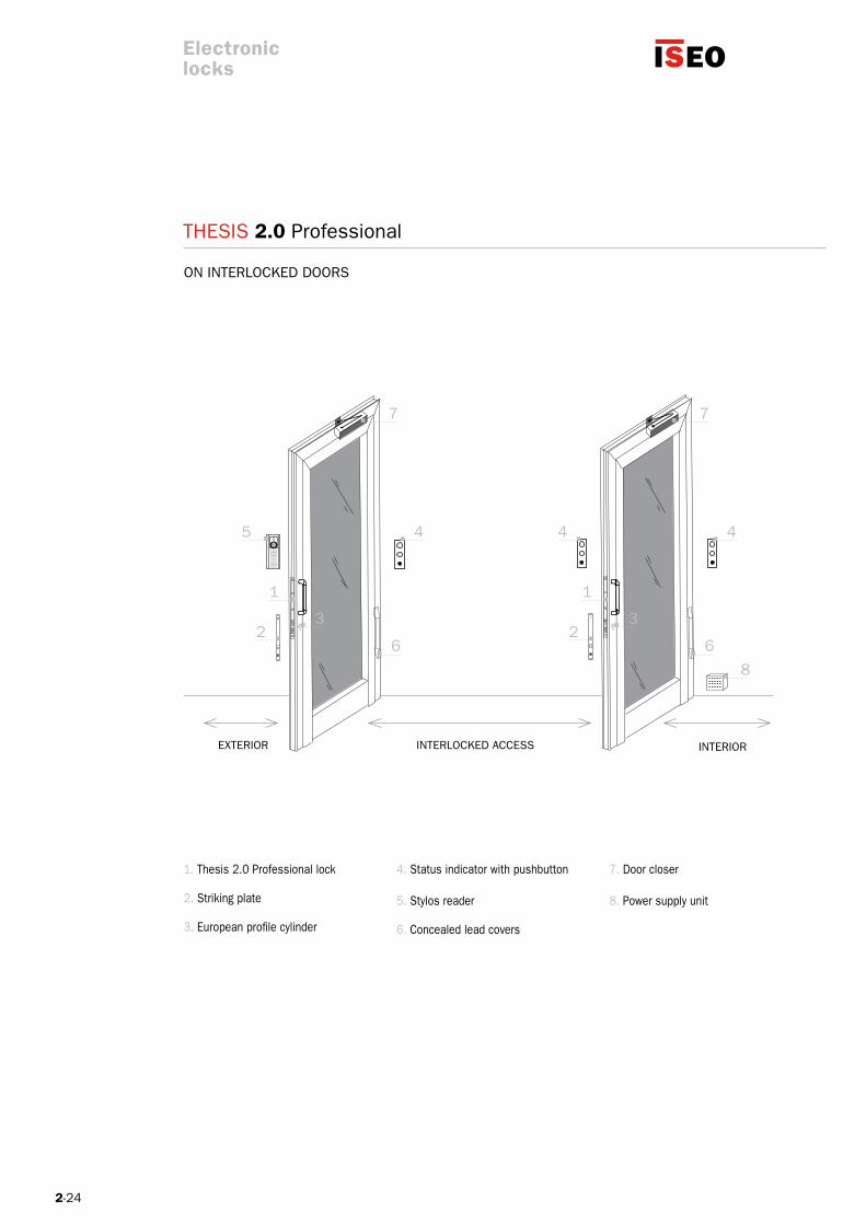
ON INTERLOCKED DOORS
1. Thesis 2.0 Professional lock
2. Striking plate
3. European profile cylinder
4. Status indicator with pushbutton
5. Stylos reader
6. Concealed lead covers
7. Door closer
8. Power supply unit
ExTERIOR INTERLOCKED ACCESS INTERIOR
Electroniclocks

2-25
THESIS 2.0 Professional
6
7
8
5
ExTERIOR INTERIOR
ON SINGLE DOORS
Electroniclocks
1. Thesis 2.0 Professional lock
2. Striking plate
3. European profile cylinder
4. Status indicator with pushbutton
5. Stylos reader
6. Concealed lead covers
7. Door closer
8. Power supply unit
2-26
07600823021
0760M823021
0760A823021
07600823521
0760M823521
0760A823521
07600824021
0760M824021
0760A824021
1
1
1
1
1
1
1
1
1
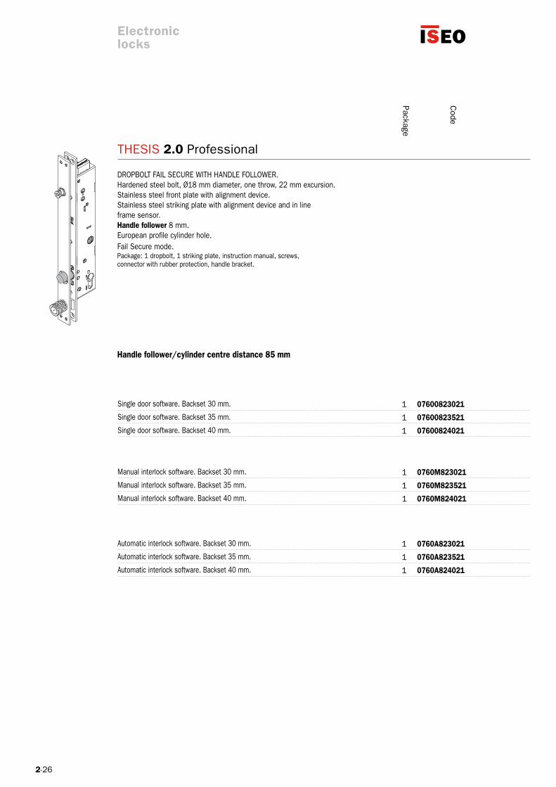
THESIS 2.0 Professional
Code
DROPBOLT FAIL SECURE WITH HANDLE FOLLOWER. Hardened steel bolt, Ø18 mm diameter, one throw, 22 mm excursion. Stainless steel front plate with alignment device.Stainless steel striking plate with alignment device and in lineframe sensor.Handle follower 8 mm. European profile cylinder hole. Fail Secure mode. Package: 1 dropbolt, 1 striking plate, instruction manual, screws, connector with rubber protection, handle bracket.
Handle follower/cylinder centre distance 85 mm
Single door software. Backset 30 mm.
Manual interlock software. Backset 30 mm.
Manual interlock software. Backset 35 mm.
Manual interlock software. Backset 40 mm.
Automatic interlock software. Backset 30 mm.
Single door software. Backset 35 mm.
Automatic interlock software. Backset 35 mm.
Single door software. Backset 40 mm.
Automatic interlock software. Backset 40 mm.
Electroniclocks
Package

2-27
07600823022
0760M823022
0760A823022
07600823522
0760M823522
0760A823522
07600824022
0760M824022
0760A824022
1
1
1
1
1
1
1
1
1
THESIS 2.0 Professional
Code
DROPBOLT FAIL SAFE WITH HANDLE FOLLOWER. Hardened steel bolt, Ø18 mm diameter, one throw, 22 mm excursion. Stainless steel front plate with alignment device.Stainless steel striking plate with alignment device and in lineframe sensor. Handle follower 8 mm. European profile cylinder hole. Fail Safe mode.Package: 1 dropbolt, 1 striking plate, instruction manual, screws, connector with rubber protection, handle bracket.
Handle follower/cylinder centre distance 85 mm
Single door software. Backset 30 mm.
Manual interlock software. Backset 30 mm.
Manual interlock software. Backset 35 mm.
Manual interlock software. Backset 40 mm.
Automatic interlock software. Backset 30 mm.
Single door software. Backset 35 mm.
Automatic interlock software. Backset 35 mm.
Single door software. Backset 40 mm.
Automatic interlock software. Backset 40 mm.
Electroniclocks
Package

2-28
07600023021
0760M023021
0760A023021
07600023521
0760M023521
0760A023521
07600024021
0760M024021
0760A024021
1
1
1
1
1
1
1
1
1
THESIS 2.0 Professional
Code
DROPBOLT FAIL SECURE WITHOUT HANDLE FOLLOWER. Hardened steel bolt, Ø14 mm diameter, one throw, 20 mm excursion. Stainless steel front plate with alignment device.Stainless steel striking plate with alignment device and in lineframe sensor. No handle follower. European profile cylinder hole.Fail Secure mode. Package: 1 dropbolt, 1 striking plate, instruction manual, screws,connector with rubber protection.
Single door software. Backset 30 mm.
Manual interlock software. Backset 30 mm.
Manual interlock software. Backset 35 mm.
Manual interlock software. Backset 40 mm.
Automatic interlock software. Backset 30 mm.
Single door software. Backset 35 mm.
Automatic interlock software. Backset 35 mm.
Single door software. Backset 40 mm.
Automatic interlock software. Backset 40 mm.
Package
Electroniclocks
2-29
07600023022
0760M023022
0760A023022
07600023522
0760M023522
0760A023522
07600024022
0760M024022
0760A024022
1
1
1
1
1
1
1
1
1
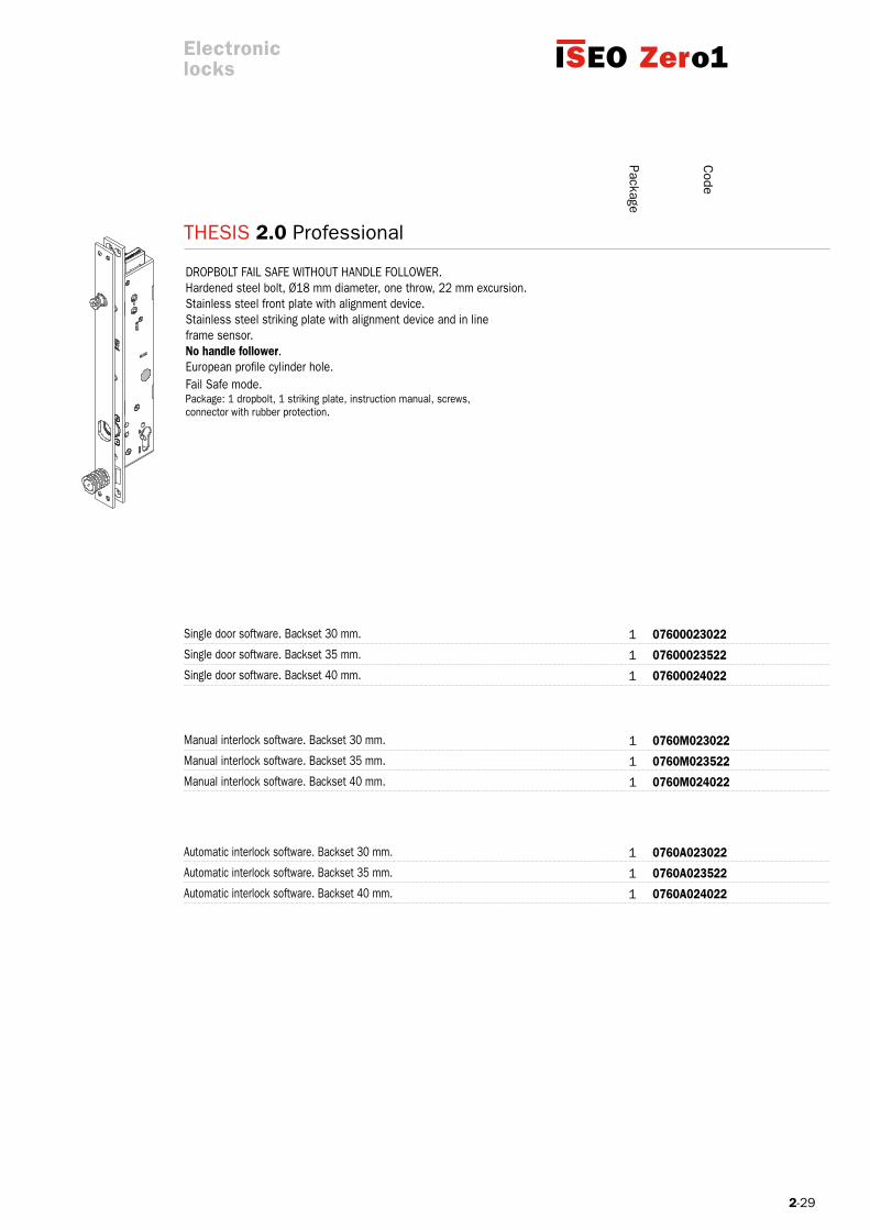
THESIS 2.0 Professional
Code
DROPBOLT FAIL SAFE WITHOUT HANDLE FOLLOWER. Hardened steel bolt, Ø18 mm diameter, one throw, 22 mm excursion. Stainless steel front plate with alignment device.Stainless steel striking plate with alignment device and in lineframe sensor. No handle follower. European profile cylinder hole.Fail Safe mode. Package: 1 dropbolt, 1 striking plate, instruction manual, screws,connector with rubber protection.
Single door software. Backset 30 mm.
Manual interlock software. Backset 30 mm.
Manual interlock software. Backset 35 mm.
Manual interlock software. Backset 40 mm.
Automatic interlock software. Backset 30 mm.
Single door software. Backset 35 mm.
Automatic interlock software. Backset 35 mm.
Single door software. Backset 40 mm.
Automatic interlock software. Backset 40 mm.
Package
Electroniclocks


2-31
Professional MiniThesis 2.0
The technology and materials chosen for THESIS 2.0 Professional Mini guarantee its durability, which is much longer than the standard requirements (even over 1 million operating cycles).
A hardened steel deadbolt with a 18 mm diameter, a 22 mm extension and a 4 mm stainless steel front plate ensure a high anti-intrusion security (level 7 ** according to EN12209 standard).
The operation is guaranteed even in case of a residual lateral load up to 15N and of a bad door alignment. This is why it is at the top of the market.
Innovative electronics with power reserve (booster) guaranteeing an efficient deadbolt movement in difficult operating con-ditions: even with 8V only!
Power supply from 8 to 30 VDC 1A. Its operation is guaranteed also in complex installations and critical situations. Flexible installation conditions and low power consumption.
Thesis 2.0 Professional Mini guarantees a trouble-free operation even if installed horizontally. It represents the ideal solution for automatic sliding doors.
The Lockbus interface allows the direct connection with Iseo Stylos Line credential readers, for a simple but effective access control management.
Available both Fail Secure mode (N.C. Normally Closed) and Fail Safe mode (N.O. Normally Open) versions.
It can operate in interlock mode (manual or automatic) for double doors without any external control device.
(**) estimated classification. Test in progress.
Thesis 2.0 Professional Mini has the same features as the Professional version but its case is smaller and it can’t be opera-ted through handle and cylinder. It is the ideal solution for installations where only the electric operation of the lock is requi-red, eventually combined with other classic closing systems. A steel deadbolt with a 22 mm extension ensures a high anti-intrusion security, and the opening operation can be controlled by transponders, contactless cards and/or PIN codes. The range of Stylos credential readers and controllers dialog with Thesis 2.0 Professional Mini in a direct way through Lockbus interface, i.e. without intermediate electronic devices, creating flexible and effective electronic access control solutions.
Key points
Electroniclocks

2-32
THESIS 2.0 Professional Mini
Electroniclocks
Deadbolt:- hardened steel;- diameter Ø18 mm;- single throw- extension 22 mm. European profile cylinder hole Handle follower (optional): 8 mm; Centre distance between handle follower and cylinder: 85 mm Front plate: - inox steel; - 30x371 mm – thickness 4 mm; - door positioning sensor and alignment device; Striking plate: - Inox steel; - 30x371 mm – thickness 4 mm; - adjustable depending on the distance between the lock and the striking plate;
Case dimensions:- thickness 27 mm- length 203 mm- depth 44 mm
DC supply voltage range: 8÷30 Vdc. Max. absorbed current power in operation: 1A. CC power supply min. characteristics: 8÷30 Vdc 15W. Opening control: - opto-isolated input 8÷24 Vdc / 12 Vac; Max voltage and current applicable to signalling relay: - 24 Vdc 1A; - 120 Vac 0.5A;
Programmable status signal: - secured door status;- door status; - latchbolt status;- command for motorized door opener; Lockbus connection: - data communication and power supply on the same 3 wire connections; - maximum length 100 mt; - secure devices authentification; - encrypted data transmission for high security against hacking; Adjustable timings: - door opening time (courtesy time): 1÷180 sec. (15 sec. default);- delayed closure time (at closing of the door): 1÷60 sec. (1 sec. default).
Technical features

2-33
THESIS 2.0 Professional Mini
Electroniclocks
Environmental features: - operating temperature: -20°C÷+60°C; - storage temperature: -25°C÷+70°C; - protection level (IP grading): IP44;
Reference Standard: UNI EN 14846:2008; grading: 3 H 8 0 0 E 7 0 1 (**) 3 H 8 0 0 E 7 0 1 (in combination with status indicator) (**)
Options and versions: Operating modes in case of power failure: Fail Secure mode (N.C. Normally Closed) Operating software: single door; bidirectional doors with manual interlock functionality (*); bidirectional doors with automatic interlock functionality (*); (*) direct connection between the 2 lock with encrypted communication. (**) estimated classification. Test in progress.
LoCAL buS
All devices belonging of the THESIS range are compatible with ISEO Lockbus.
Lockbus is a powerful multypeint bus sharing data transmission and power supply on the same 3-wire connection for utmost flexibility, easy installation and consequently, cost optimization.
Lockbus highlights: Data transmission and power supply on the same 3-wire connection up to 100 m;
Self-adjusting power supply from 8 Vdc to 30 Vdc;
Secure device authentication (among readers and actuators) and encrypteddata transmission for high security against manipulation.
Lockbus

2-34
THESIS 2.0 Professional Mini
6 6
7 7
8
5
1. Thesis 2.0 Professional Mini lock
2. Striking plate
3. European profile cylinder
4. Status indicator with pushbutton
5. Stylos reader
6. Concealed lead covers
7. Door closer
8. Power supply unit
ExTERIOR INTERLOCKED ACCESS INTERIOR
ON INTERLOCKED DOORS
Electroniclocks

2-35
6
7
8
5
THESIS 2.0 Professional Mini
ExTERIOR INTERIOR
1. Thesis 2.0 Professional Mini lock
2. Striking plate
3. European profile cylinder
4. Status indicator with pushbutton
5. Stylos reader
6. Concealed lead covers
7. Door closer
8. Power supply unit
ON SINGLE DOORS
Electroniclocks
2-36
THESIS 2.0 Professional Mini
Code
07800020021
0780M020021
0780A020021
1
1
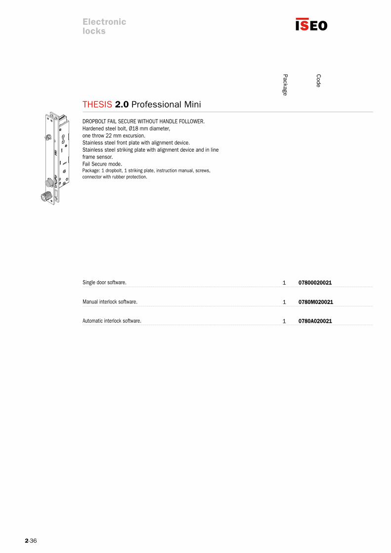
1
DROPBOLT FAIL SECURE WITHOUT HANDLE FOLLOWER. Hardened steel bolt, Ø18 mm diameter,one throw 22 mm excursion. Stainless steel front plate with alignment device.Stainless steel striking plate with alignment device and in lineframe sensor. Fail Secure mode. Package: 1 dropbolt, 1 striking plate, instruction manual, screws, connector with rubber protection.
Single door software.
Manual interlock software.
Automatic interlock software.
Electroniclocks
Package
2-37
THESIS 2.0 Professional Mini
Code
07800020022
0780M020022
0780A020022
1
1
1
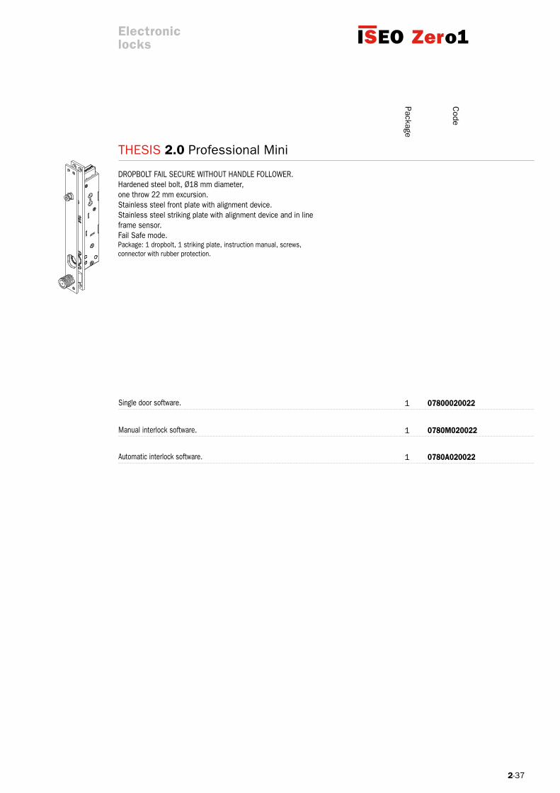
DROPBOLT FAIL SECURE WITHOUT HANDLE FOLLOWER. Hardened steel bolt, Ø18 mm diameter,one throw 22 mm excursion. Stainless steel front plate with alignment device.Stainless steel striking plate with alignment device and in lineframe sensor. Fail Safe mode. Package: 1 dropbolt, 1 striking plate, instruction manual, screws, connector with rubber protection.
Single door software.
Manual interlock software.
Automatic interlock software.
Electroniclocks
Package
2-38
0000098075000
0000098076000
0000098078000
1
1
1
5E000002055
Code
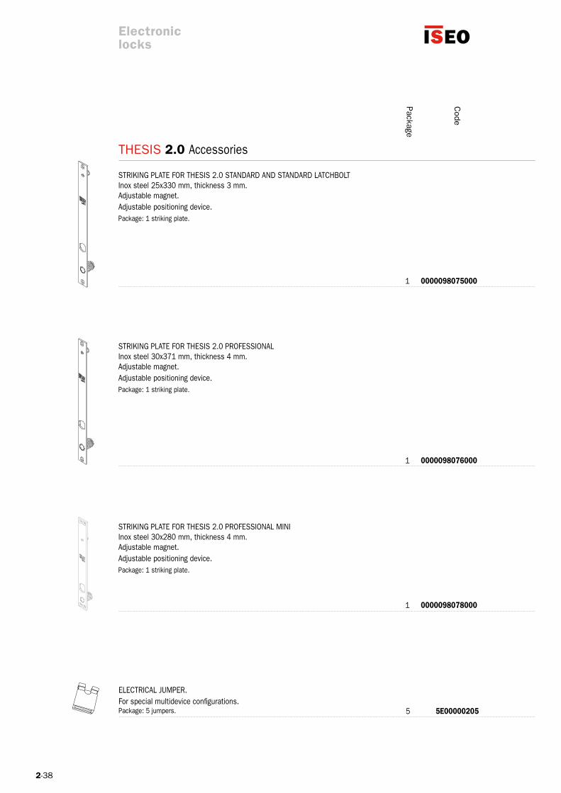
STRIKING PLATE FOR THESIS 2.0 STANDARD AND STANDARD LATCHBOLT Inox steel 25x330 mm, thickness 3 mm. Adjustable magnet. Adjustable positioning device. Package: 1 striking plate.
STRIKING PLATE FOR THESIS 2.0 PROFESSIONAL Inox steel 30x371 mm, thickness 4 mm. Adjustable magnet. Adjustable positioning device. Package: 1 striking plate.
STRIKING PLATE FOR THESIS 2.0 PROFESSIONAL MINI Inox steel 30x280 mm, thickness 4 mm. Adjustable magnet. Adjustable positioning device. Package: 1 striking plate.
ELECTRICAL jUMPER.For special multidevice configurations.Package: 5 jumpers.
Electroniclocks
PackageTHESIS 2.0 Accessories
2-39
FXK750
FXKVAL750
FSAPL2T00000000
FSAPL2TA0000000
50800IP54MTTS
58700MTPADS00
1
1
1
1
1
1
Code
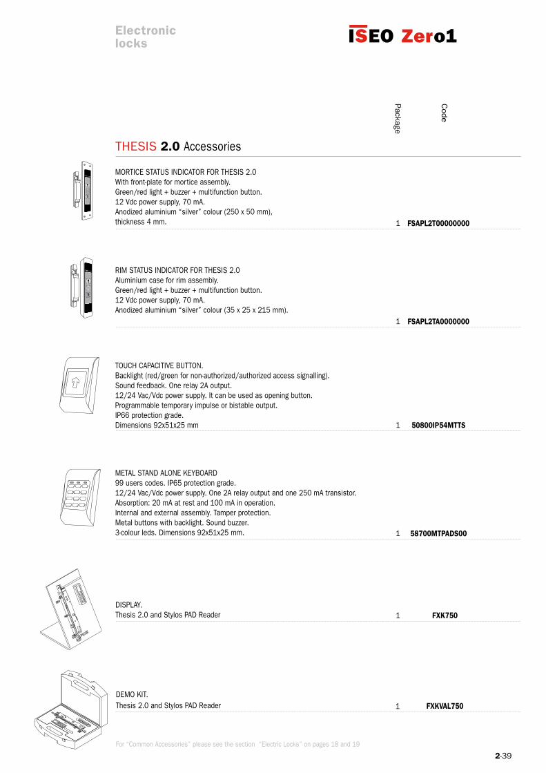
DISPLAy.Thesis 2.0 and Stylos PAD Reader
DEMO KIT.Thesis 2.0 and Stylos PAD Reader
Electroniclocks
PackageTHESIS 2.0 Accessories
MORTICE STATUS INDICATOR FOR THESIS 2.0With front-plate for mortice assembly.Green/red light + buzzer + multifunction button. 12 Vdc power supply, 70 mA. Anodized aluminium “silver” colour (250 x 50 mm), thickness 4 mm.
RIM STATUS INDICATOR FOR THESIS 2.0Aluminium case for rim assembly.Green/red light + buzzer + multifunction button.12 Vdc power supply, 70 mA.Anodized aluminium “silver” colour (35 x 25 x 215 mm).
TOUCH CAPACITIVE BUTTON.Backlight (red/green for non-authorized/authorized access signalling).Sound feedback. One relay 2A output.12/24 Vac/Vdc power supply. It can be used as opening button.Programmable temporary impulse or bistable output. IP66 protection grade. Dimensions 92x51x25 mm
METAL STAND ALONE KEyBOARD99 users codes. IP65 protection grade.12/24 Vac/Vdc power supply. One 2A relay output and one 250 mA transistor.Absorption: 20 mA at rest and 100 mA in operation.Internal and external assembly. Tamper protection.Metal buttons with backlight. Sound buzzer.3-colour leds. Dimensions 92x51x25 mm.
For “Common Accessories” please see the section “Electric Locks” on pages 18 and 19


2-41
7 5 0 1 3 2 1 A b3
Top Exit DGTTop Exit DGT is a smart closing device conceived and manufactured specifically for applications on metal frames in steel and aluminum.
The motorized movement of the deadbolts (and latchbolt) during both opening and closing operations is controlled by specific sensors and a powerful microprocessor, which guarantee constant security.
The lock software allows to manage the “hold open” function: the deadbolts are constantly unlocked allowing free entrance to anybody.
Top Exit DGT is available in three different versions that suit any application exigency:- TyPE A with motorized deadbolts and adjustable roller latchbolt- TyPE B with motorized deadbolts and mechanical latchbolt (manual operation) - TyPE C with motorized deadbolts and latchbolt
All the versions can operate mechanically too, because the european cylinder and/or panic exit device operations don’t depend on power supply and impediments deriving from the contemporary operation of the motor.
The control unit allows the opening from exterior through accessories such as proximity readers, radio remote controls and electronic keys and through the connection to centralized access control systems.
Central or three locking points lock with rotating deadbolts.European profile cylinder hole.Handle follower 8 mm.Backset 35 mm.Centre distance 85 mm.Deadbolts status sensors, in line frame and failed locking through deadbolt signals,motorized latchbolt, handle status according to versions.“Hold open” function.5 or 15 sec. courtesy time (door opening time) according to versions.Lockbus interface (optional).
It is certified Top Exit DGT has been conceived and manufactured in compliance with European standards UNI EN 1125, EN 12209, 15685 and 14846.
Key points
Main features
Electroniclocks
Classification example:

2-42
Top Exit DGT
Internal side
1. Control unit
2. Concealed lead covers
3. 220 Vac electric power
Installation scheme
Electroniclocks
2-43
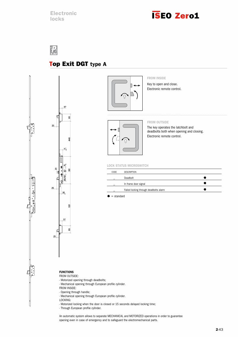
LoCK STATuS MICroSWITCH
CODE DESCRIPTION
_ Deadbolt
_ In frame door signal
_ Failed locking through deadbolts alarm
FroM INSIDE
Key to open and close.Electronic remote control.
FroM ouTSIDE The key operates the latchbolt and deadbolts both when opening and closing.Electronic remote control.
Top Exit DGT type A
FuNCTIoNSFROM OUTSIDE:- Motorized opening through deadbolts;- Mechanical opening through European profile cylinder.FROM INSIDE:- Opening through handle;- Mechanical opening through European profile cylinder.LOCKING:- Motorized locking when the door is closed or 15 seconds delayed locking time;- Through European profile cylinder.
An automatic system allows to separate MECHANICAL and MOTORIZED operations in order to guarantee opening even in case of emergency and to safeguard the electromechanical parts.
Electroniclocks
= standard

2-44
Code
24
5
25
3
Backset 35 mm. Centre distance 85 mm. 1 0000017422885
Top Exit DGT type A
Backset 35 mm. Centre distance 85 mm. 1 0000007222885
TECHNICAL FEATurES ToP LINE Power supply 230Vac 20W Dimensions 210x120x65 mm Operating functions: -10+60°C Courtesy time 5/15 sec. Deleyed locking time 2 sec. Status relay 3
SINGLE POINT LOCK. In compliance with UNI EN 14846 standard.Flat STAINLESS steel front plate section mm 25x3, length mm 536.Supplied with: Control unit. Connecting cables. Fixing screws.Handle follower.
MULTIPOINT LOCK. In compliance with UNI EN 14846 and prEN 15685 standards.U-shaped STAINLESS steel front plate section mm 24x5, length mm 2300.Supplied with: Control unit. Connecting cables. Fixing screws.Handle follower.
Electroniclocks
Package
Top Exit DGT type A
Full-size scale
Full-size scale

2-45
0425
Top Exit DGT type b
FroM INSIDE
Key to open and close.
Handle to open bolts and deadbolts.
Electronic remote control.
FroM ouTSIDE The key operates the latchbolt and deadbolts both when opening and closing.When the deadbolts are unlocked, the handle operates the latchbolt.Electronic remote control.
Doors opening direction.
FuNCTIoNSFROM OUTSIDE:- Motorized opening through deadbolts and latchbolt operation through handle;- Mechanical opening through European profile cylinder.FROM INSIDE:- Opening through handle;- Mechanical opening through European profile cylinder.LOCKING:- Motorized locking when the door is c losed or 15 seconds delayed locking time;- Through European profile cylinder.
An automatic system allows to separate mechanical and motorized operations in order to guarantee opening even in case of emergency and to safeguard the electromechanical parts.
Electroniclocks
If you wish to order the lock with status microswitch, please add the reference codes above to the lock code. Example: 1741688501x Top Exit DGT E 35 I 85 with handle microswitch.
CoNTroL MICroSWITCH
CODE DESCRIPTION
_ Deadbolt
_ In frame door signal
_ Failed locking through deadbolts alarm
x Handle control
= Standard = On request
Outside rightDIN left
Inside leftDIN right
INTERNALExTERNAL

2-46
25
3
24
5
Code
Backset 35 mm. Centre distance 85 mm. RIGHT HAND. 1 000001741688501 Backset 35 mm. Centre distance 85 mm. LEFT HAND. 1 000001741688502
SINGLE POINT LOCK. In compliance with UNI EN 14846 standard.Flat STAINLESS steel front plate section mm 25x3, length mm 536.Supplied with: Control unit. Connecting cables. Fixing screws.Splitted handle follower.
Top Exit DGT type b
MULTIPOINT LOCK. In compliance with UNI EN 14846 and prEN 15685 standards.U-shaped STAINLESS steel front plate section mm 24x5, length mm 2300.Supplied with: Control unit cables. Fixing screws.Splitted handle follower.
Backset 35 mm. Centre distance 85 mm. RIGHT HAND. 1 000000721688501 Backset 35 mm. Centre distance 85 mm. LEFT HAND. 1 000000721688502
Full-size scale
Full-size scale
Electroniclocks
Package
TECHNICAL FEATurES ToP LINE Power supply 230Vac 20W Dimensions 210x120x65 mm Operating functions: -10+60°C Courtesy time 5/15 sec. Deleyed locking time 2 sec. Status relay 3
Top Exit DGT type b
2-47
0425
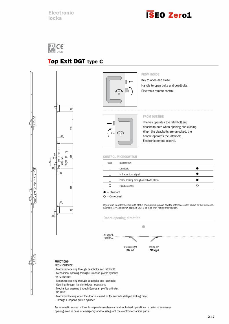
Top Exit DGT type C
FroM ouTSIDE
The key operates the latchbolt and deadbolts both when opening and closing.When the deadbolts are unlocked, the handle operates the latchbolt.Electronic remote control.
FuNCTIoNSFROM OUTSIDE:- Motorized opening through deadbolts and latchbolt;- Mechanical opening through European profile cylinder.FROM INSIDE:- Motorized opening through deadbolts and latchbolt;- Opening through handle follower operation;- Mechanical opening through European profile cylinder.LOCKING:- Motorized locking when the door is closed or 15 seconds delayed locking time;- Through European profile cylinder.
An automatic system allows to separate mechanical and motorized operations in order to guarantee opening even in case of emergency and to safeguard the electromechanical parts.
Electroniclocks
FroM INSIDE
Key to open and close.
Handle to open bolts and deadbolts.
Electronic remote control.
Doors opening direction.
If you wish to order the lock with status microswitch, please add the reference codes above to the lock code. Example: 1741688501x Top Exit DGT E 35 I 85 with handle microswitch.
CoNTroL MICroSWITCH
CODE DESCRIPTION
_ Deadbolt
_ In frame door signal
_ Failed locking through deadbolts alarm
x Handle control
= Standard = On request
Outside rightDIN left
Inside leftDIN right
INTERNALExTERNAL
2-48
25
3
24
5
Code
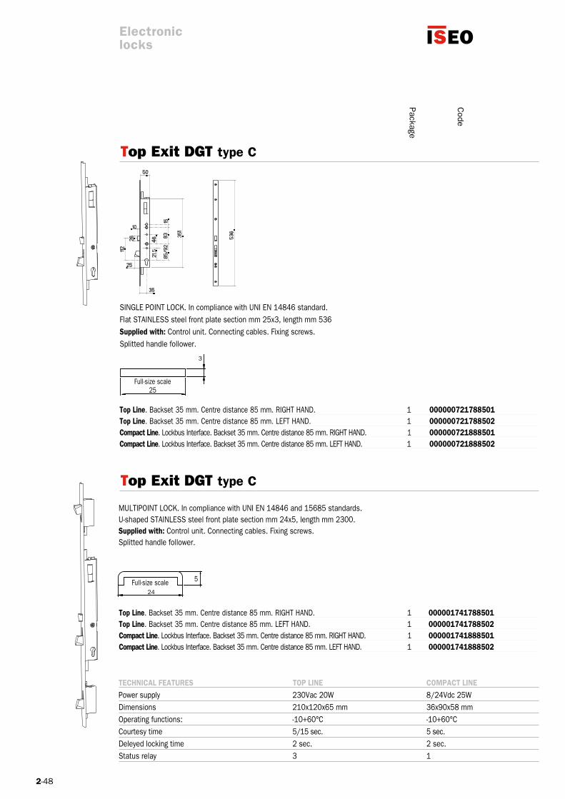
TECHNICAL FEATurES ToP LINE CoMPACT LINEPower supply 230Vac 20W 8/24Vdc 25WDimensions 210x120x65 mm 36x90x58 mmOperating functions: -10+60°C -10+60°CCourtesy time 5/15 sec. 5 sec.Deleyed locking time 2 sec. 2 sec.Status relay 3 1
SINGLE POINT LOCK. In compliance with UNI EN 14846 standard.Flat STAINLESS steel front plate section mm 25x3, length mm 536Supplied with: Control unit. Connecting cables. Fixing screws.Splitted handle follower.
Top Exit DGT type C
Top Exit DGT type C
MULTIPOINT LOCK. In compliance with UNI EN 14846 and 15685 standards.U-shaped STAINLESS steel front plate section mm 24x5, length mm 2300.Supplied with: Control unit. Connecting cables. Fixing screws.Splitted handle follower.
Top Line. Backset 35 mm. Centre distance 85 mm. RIGHT HAND. 1 000000721788501 Top Line. Backset 35 mm. Centre distance 85 mm. LEFT HAND. 1 000000721788502 Compact Line. Lockbus Interface. Backset 35 mm. Centre distance 85 mm. RIGHT HAND. 1 000000721888501 Compact Line. Lockbus Interface. Backset 35 mm. Centre distance 85 mm. LEFT HAND. 1 000000721888502
Top Line. Backset 35 mm. Centre distance 85 mm. RIGHT HAND. 1 000001741788501 Top Line. Backset 35 mm. Centre distance 85 mm. LEFT HAND. 1 000001741788502 Compact Line. Lockbus Interface. Backset 35 mm. Centre distance 85 mm. RIGHT HAND. 1 000001741888501 Compact Line. Lockbus Interface. Backset 35 mm. Centre distance 85 mm. LEFT HAND. 1 000001741888502
Full-size scale
Full-size scale
Electroniclocks
Package
2-49
Code
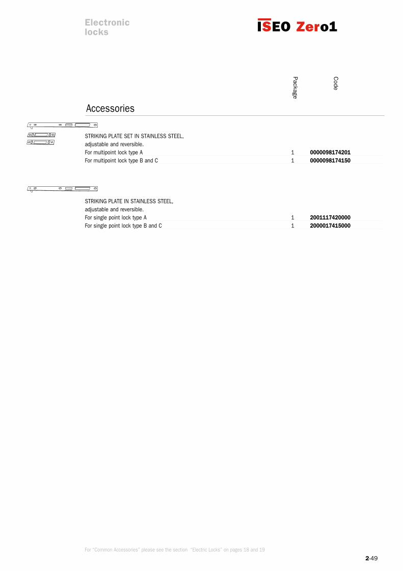
STRIKING PLATE SET IN STAINLESS STEEL,adjustable and reversible.For multipoint lock type A 1 0000098174201 For multipoint lock type B and C 1 0000098174150
STRIKING PLATE IN STAINLESS STEEL, adjustable and reversible.For single point lock type A 1 2001117420000 For single point lock type B and C 1 2000017415000
PackageAccessories
Electroniclocks
For “Common Accessories” please see the section “Electric Locks” on pages 18 and 19

2-51
Three-point locking with top and bottom hook deadbolts.
Deadbolts automatic mechanical relocking when the door is closed.
Deadbolts and latchbolt electromechanical opening.
Deadbolts lock and deviators 27 mm throw, with anti-drill and anti-cut cover plates in carbonitrided steel – maximum anti-intrusion resistance (7) according to European standard UNI EN14846:2008.
European cylinder hole.
8 mm handle follower.
Backset 35/40 mm.
Backset 92 mm.
Deadbolts status sensors. When the deadbolts are completely retracted a sound signal is produced.
“Hold open” function.
Locking time: 5 or 15 sec. according to different versions (time after which the door is automatically locked if it is not been opened after the opening impulse).
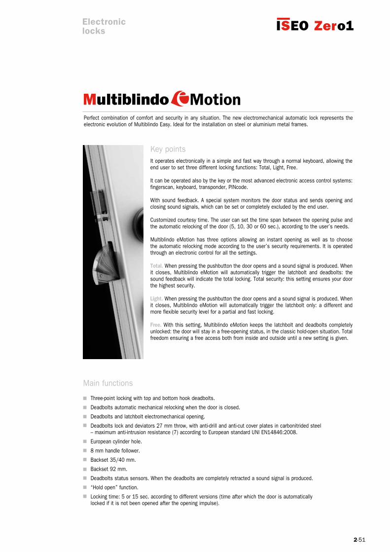
Perfect combination of comfort and security in any situation. The new electromechanical automatic lock represents the electronic evolution of Multiblindo Easy. Ideal for the installation on steel or aluminium metal frames.
It operates electronically in a simple and fast way through a normal keyboard, allowing the end user to set three different locking functions: Total, Light, Free.
It can be operated also by the key or the most advanced electronic access control systems: fingerscan, keyboard, transponder, PINcode.
With sound feedback. A special system monitors the door status and sends opening and closing sound signals, which can be set or completely excluded by the end user.
Customized courtesy time. The user can set the time span between the opening pulse and the automatic relocking of the door (5, 10, 30 or 60 sec.), according to the user’s needs.
Multiblindo eMotion has three options allowing an instant opening as well as to choose the automatic relocking mode according to the user’s security requirements. It is operated through an electronic control for all the settings.
Total. When pressing the pushbutton the door opens and a sound signal is produced. When it closes, Multiblindo eMotion will automatically trigger the latchbolt and deadbolts: the sound feedback will indicate the total locking. Total security: this setting ensures your door the highest security.
Light. When pressing the pushbutton the door opens and a sound signal is produced. When it closes, Multiblindo eMotion will automatically trigger the latchbolt only: a different and more flexible security level for a partial and fast locking.
Free. With this setting, Multiblindo eMotion keeps the latchbolt and deadbolts completely unlocked: the door will stay in a free-opening status, in the classic hold-open situation. Total freedom ensuring a free access both from inside and outside until a new setting is given.
Key points
Main functions
Electroniclocks

2-52
X 8 o 0 M 7 1 33
CLASS
C
VDS is an indipendent German institute. A VDS certification helps end users to distinguish high quality from mediocre products and services. ISEO Serrature has obtained the highest security certification for Multiblindo product range, class C.
With sound feedbackA special system monitors the door status and sends opening and closing sound signals, which can be set or completely excluded by the end user.
It is certified according to EN14846:08 and prEN15685:09 European standards.Multiblindo eMotion ensures top-level intrusion protection; it doesn’t lose the settings in case of a blackout and, if necessary, it always assures the mechanical key or handle action.
Example of certification:
Electroniclocks

2-53
1.1
Installation scheme
Internal side
1. Mortice lock 1.1 Cable for remote pushbutton (supplied with the lock)2. Concealed lead covers
3. Striking plate
Electroniclocks
2-54
24
24
24
763
22
22
73
3
24
24
24
763
22
22
73
6
Code
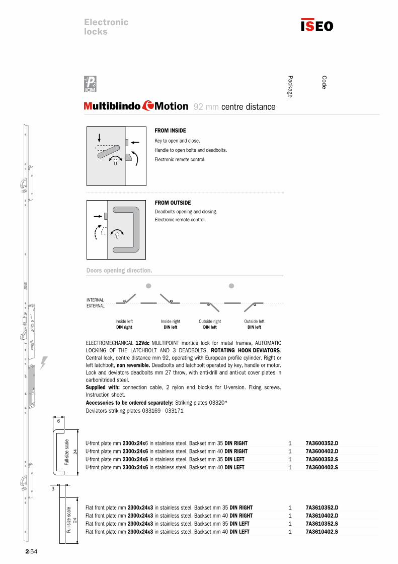
U-front plate mm 2300x24x6 in stainless steel. Backset mm 35 DIN rIGHT 1 7A3600352.D U-front plate mm 2300x24x6 in stainless steel. Backset mm 40 DIN rIGHT 1 7A3600402.D 000,04U-front plate mm 2300x24x6 in stainless steel. Backset mm 35 DIN LEFT 1 7A3600352.S 000,04U-front plate mm 2300x24x6 in stainless steel. Backset mm 40 DIN LEFT 1 7A3600402.S 000,04
Flat front plate mm 2300x24x3 in stainless steel. Backset mm 35 DIN rIGHT 1 7A3610352.D 000,04Flat front plate mm 2300x24x3 in stainless steel. Backset mm 40 DIN rIGHT 1 7A3610402.D 000,04Flat front plate mm 2300x24x3 in stainless steel. Backset mm 35 DIN LEFT 1 7A3610352.S 000,04Flat front plate mm 2300x24x3 in stainless steel. Backset mm 40 DIN LEFT 1 7A3610402.S
ELECTROMECHANICAL 12Vdc MULTIPOINT mortice lock for metal frames, AUTOMATIC LOCKING OF THE LATCHBOLT AND 3 DEADBOLTS, roTATING HooK DEVIATorS. Central lock, centre distance mm 92, operating with European profile cylinder. Right or left latchbolt, non reversible. Deadbolts and latchbolt operated by key, handle or motor. Lock and deviators deadbolts mm 27 throw, with anti-drill and anti-cut cover plates in carbonitrided steel. Supplied with: connection cable, 2 nylon end blocks for U-version. Fixing screws. Instruction sheet.Accessories to be ordered separately: Striking plates 03320* Deviators striking plates 033169 - 033171
92 mm centre distance
FroM INSIDE
Key to open and close.
Handle to open bolts and deadbolts.
Electronic remote control.
FroM ouTSIDE Deadbolts opening and closing.
Electronic remote control.
Doors opening direction.
Outside rightDIN left
Inside leftDIN right
Outside leftDIN left
Inside rightDIN left
Full-s
ize s
cale
Full-s
ize s
cale
Electroniclocks
Package
INTERNALExTERNAL
2-55
Code
Strikingplates
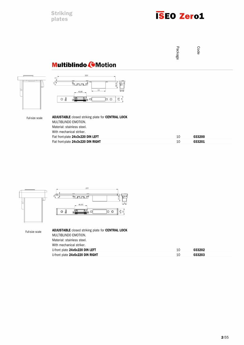
ADjuSTAbLE closed striking plate for CENTrAL LoCK MULTIBLINDO EMOTION. Material: stainless steel. With mechanical striker.Flat front-plate 24x3x220 DIN LEFT 10 033200 Flat front-plate 24x3x220 DIN rIGHT 10 033201 16,35
ADjuSTAbLE closed striking plate for CENTrAL LoCK MULTIBLINDO EMOTION. Material: stainless steel. With mechanical striker. U-front plate 24x6x220 DIN LEFT 10 033202 U-front plate 24x6x220 DIN rIGHT 10 033203 ,35
Full-size scale
Full-size scale
Package

2-56
24
180
3 30.5
24
180
3 30.5
Code
Strikingplates
AdjuStAble closed striking plate for hook deviAtorSMULTIBLINDO EMOTION. Material: stainless steel. Flat front plate 24X3X180. 10 033169 14,60
AdjuStAble closed striking plate for hook deviAtorSMULTIBLINDO EMOTION.Material: stainless steel.U-front plate 24X6X180. 10 033171 60
Full-size scale
Full-size scale
Package
For “Common Accessories” please see the section “Electric Locks” on pages 18 and 19


2-59
M 8 0 0 M 7 1 13
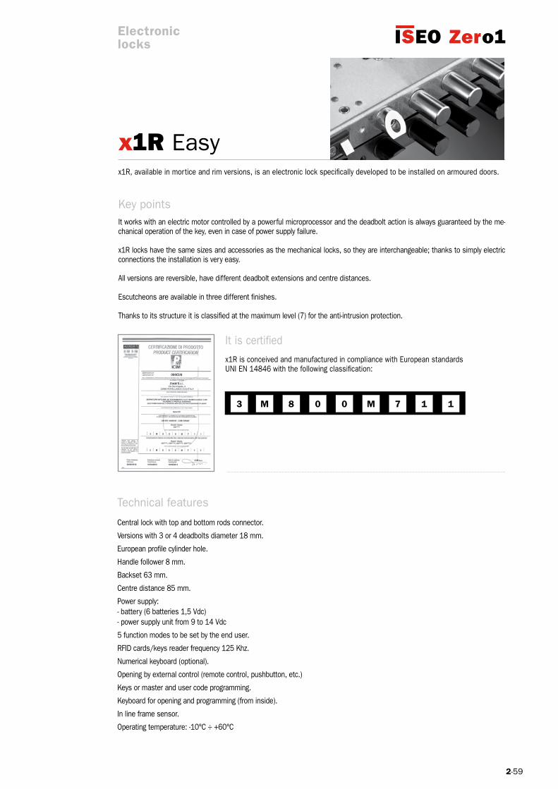
x1R Easy
Technical features
Central lock with top and bottom rods connector.
Versions with 3 or 4 deadbolts diameter 18 mm.
European profile cylinder hole.
Handle follower 8 mm.
Backset 63 mm.
Centre distance 85 mm.
Power supply:- battery (6 batteries 1,5 Vdc)- power supply unit from 9 to 14 Vdc
5 function modes to be set by the end user.
RFID cards/keys reader frequency 125 Khz.
Numerical keyboard (optional).
Opening by external control (remote control, pushbutton, etc.)
Keys or master and user code programming.
Keyboard for opening and programming (from inside).
In line frame sensor.
Operating temperature: -10°C ÷ +60°C
It is certified x1R is conceived and manufactured in compliance with European standards UNI EN 14846 with the following classification:
x1R, available in mortice and rim versions, is an electronic lock specifically developed to be installed on armoured doors.
It works with an electric motor controlled by a powerful microprocessor and the deadbolt action is always guaranteed by the me-chanical operation of the key, even in case of power supply failure.
x1R locks have the same sizes and accessories as the mechanical locks, so they are interchangeable; thanks to simply electric connections the installation is very easy.
All versions are reversible, have different deadbolt extensions and centre distances.
Escutcheons are available in three different finishes.
Thanks to its structure it is classified at the maximum level (7) for the anti-intrusion protection.
Key points
Electroniclocks
2-60
1
2
2
2.1
2.1
1.2
3
3.1
6
7
1.1
9
10
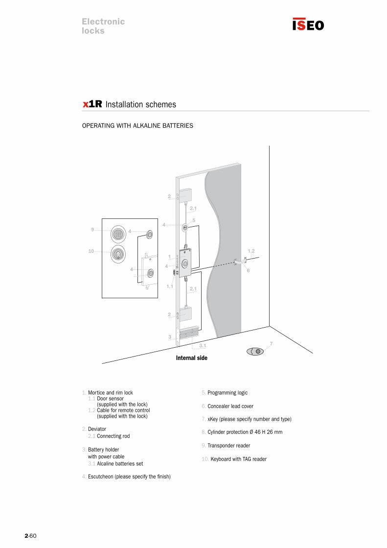
OPERATING WITH ALKALINE BATTERIES
x1R Installation schemes
Internal side
Electroniclocks
1. Mortice and rim lock 1.1 Door sensor (supplied with the lock) 1.2 Cable for remote control (supplied with the lock)
2. Deviator 2.1 Connecting rod
3. Battery holder with power cable 3.1 Alcaline batteries set
4. Escutcheon (please specify the finish)
5. Programming logic
6. Concealer lead cover
7. xKey (please specify number and type)
8. Cylinder protection Ø 46 H 26 mm
9. Transponder reader
10. Keyboard with TAG reader

2-61
1.2
6
7
1
2
2
2.1
2.1
3
3.1
1.1
11
13
14
12
8
9
10
OPERATING WITH RECHARGEABLE BATTERIES
x1R Installation schemes
Internal side
Electroniclocks
1. Mortice and rim lock 1.1 Door sensor (supplied with the lock) 1.2 Cable for remote control (supplied with the lock)
2. Deviator 2.1 Connecting rod
3. Battery holder with power cable 3.1 Alcaline batteries set
4. Escutcheon (please specify the finish)
5. Programming logic
6. Concealer lead cover
7. xKey (please specify number and type)
8. Cylinder protection Ø 46 H 26 mm
9. Transponder reader
10. Keyboard with TAG reader
11. Radio remote control
12. Receiver for radio remote control
13. Battery charger
14. Transformer
2-62
1.2
6
7
1
2
2
2.1
2.1
3
3.1
1.1
11
12
8
9
10
13
14
Electroniclocks
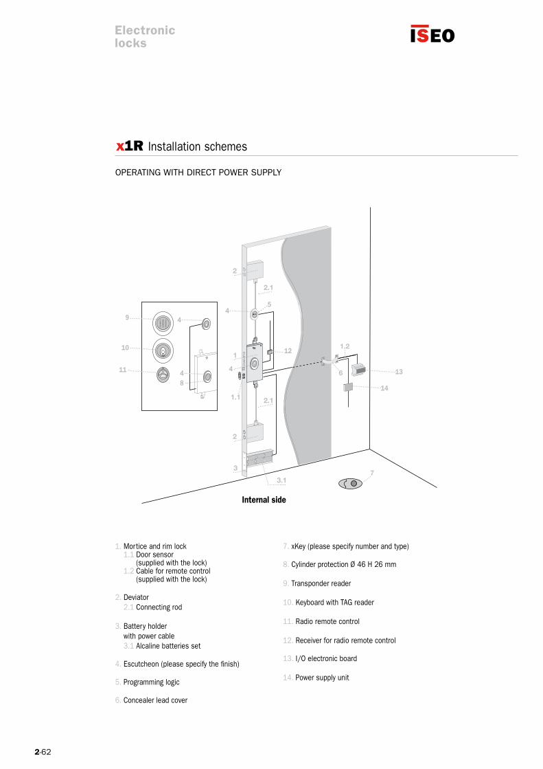
Internal side
OPERATING WITH DIRECT POWER SUPPLy
x1R Installation schemes
1. Mortice and rim lock 1.1 Door sensor (supplied with the lock) 1.2 Cable for remote control (supplied with the lock)
2. Deviator 2.1 Connecting rod
3. Battery holder with power cable 3.1 Alcaline batteries set
4. Escutcheon (please specify the finish)
5. Programming logic
6. Concealer lead cover
7. xKey (please specify number and type)
8. Cylinder protection Ø 46 H 26 mm
9. Transponder reader
10. Keyboard with TAG reader
11. Radio remote control
12. Receiver for radio remote control
13. I/O electronic board
14. Power supply unit
2-63
Code
0000006980328
0000006981328
0000006980337
0000006981337
0000006980028
0000006980037
x1R Easy
Electroniclocks
Package
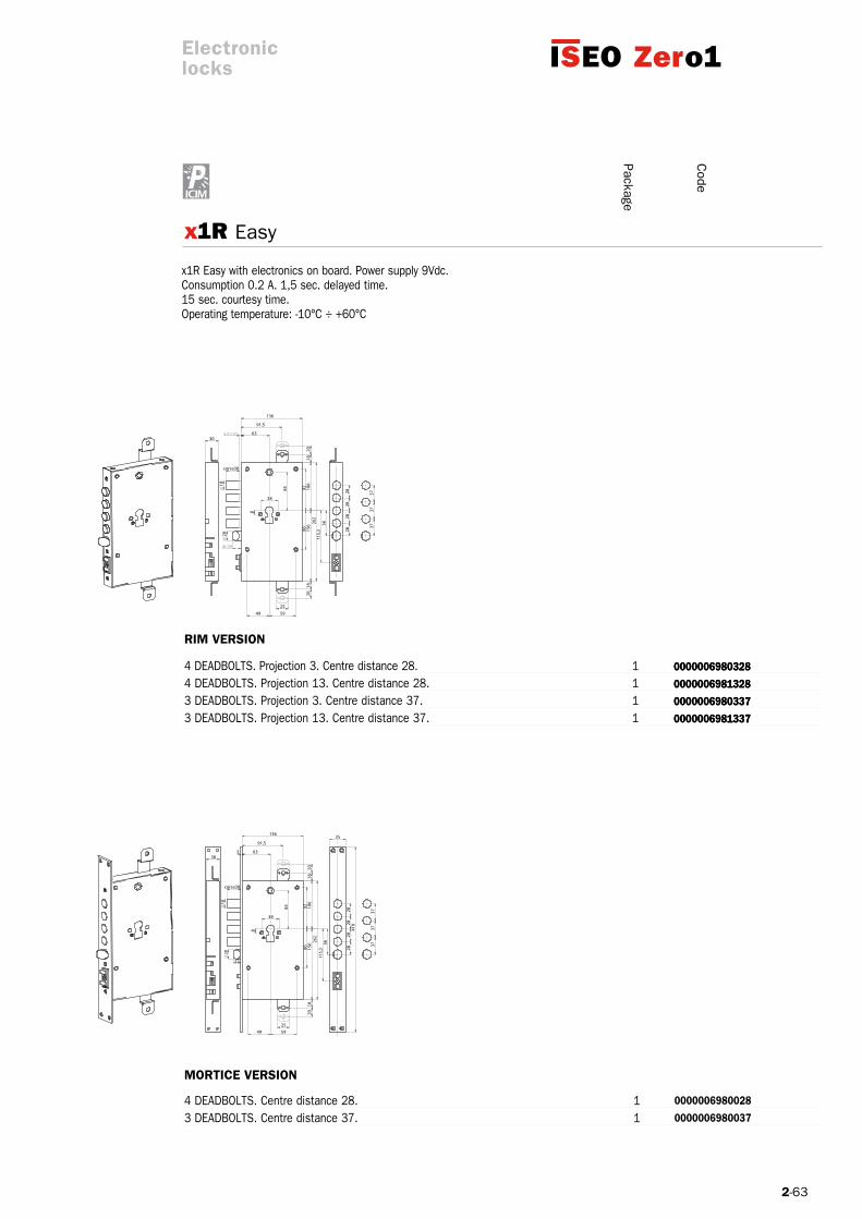
4 DEADBOLTS. Projection 3. Centre distance 28. 1 4 DEADBOLTS. Projection 13. Centre distance 28. 1 03 DEADBOLTS. Projection 3. Centre distance 37. 1 3 DEADBOLTS. Projection 13. Centre distance 37. 1
4 DEADBOLTS. Centre distance 28. 1 3 DEADBOLTS. Centre distance 37. 1
x1R Easy with electronics on board. Power supply 9Vdc.Consumption 0.2 A. 1,5 sec. delayed time.15 sec. courtesy time.Operating temperature: -10°C ÷ +60°C
0000006980328
0000006981328
0000006980337
0000006981337
rIM VErSIoN
MorTICE VErSIoN

2-64
1 0000098PI0698
1 0000098TE0698
XCArD 10 XKArD69800125
x.KEy TRANSPONDER.
Please specify the size of the cylinders for the version with mechanical key.Suitable for x1R Easy.
Electroniclocks
Package
Code
TRANSPONDER READER (TAG). Suitable for x1R Easy.
INTERNAL OPENING PUSHBUTTONS AND PROGRAMMING BOARD.Suitable for x1R Easy.
xCARD USER125 KHz. Suitable for x1R EASy.
transponder only (red) 1 XKEy006980000 0
transponder only (grey) 1 XKEy006980200
transponder with key (blue)* 1 XKEy006980100
3 transponders (red) 1 XKEy016980000
3 transdponders (grey) 1 XKEy016980200
3 transponders with key (blue)* 1 XKEy016980100
x1R Accessories
*Cylinders and keys to be ordered separately.
2-65
1 5870006980009
bA
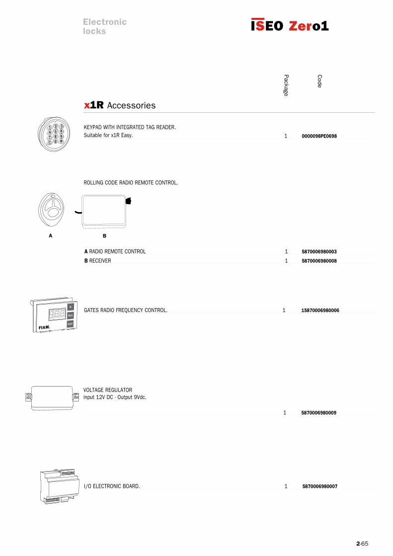
1 0000098PE0698
Electroniclocks
Package
Code
VOLTAGE REGULATOR input 12V DC - Output 9Vdc.
GATES RADIO FREQUENCy CONTROL. 1 15870006980006
I/O ELECTRONIC BOARD. 1 587000698000714,60
KEyPAD WITH INTEGRATED TAG READER.Suitable for x1R Easy.
ROLLING CODE RADIO REMOTE CONTROL.
A RADIO REMOTE CONTROL 1 5870006980003 14,60
b RECEIVER 1 5870006980008 14,60
x1R Accessories

2-66
1 5820006980000
1 5870000003809
Code
x1R Accessories
TRANSFORMERinput 220 Vac-Output 12 V-15 VA
POWER SUPPLy UNIT 9 V – 2,89 A for direct power supply(without batteries)
No. 6 BATTERIES TyPE D 1,5V
BATTERy HOLDER (batteries not included) 1 582006980000514,60
ALKALINE 1 5820060000006 14,60
RECHARGEABLE 1 5820060000016 14,60
BATTERy CHARGER. 1 5820060010016 14,60
Electroniclocks
Package

2-67
I=28mm 1 2000006980028
I=37mm 1 2000006980037
194
28 28 28 28
373737
30
10 0000098N00CIL
Code
UNIVERSAL SINGLE ESCUTSCHEON made of a nylon base, brass cover and fixing screws. Finish:varnished polished brass (OLV) – polished chrome (CRL)satin chrome (CRS) – aluminium bronze (BRO).
aluminium bronze (BRO) 1 0000098N0Xbro
polished chrome (CRL) 1 0000098N0XCrL
satin chrome (CRS) 1 0000098NoXCrS 60
varnished polished brass (OLV) 1 0000098N0XoLV
aluminium bronze (BRO) 10 0000098N1Dbro
polished chrome (CRL) 10 0000098N1DCrL
satin chrome (CRS) 10 0000098N1DCrS
varnished polished brass (OLV) 10 0000098N1DoLV
CHROME-PLATED STEEL STRIKING PLATE COVER.
STEEL SUPPORTING PLATE thickness 3 mm. 1 0000099069800 14,60
NyLON INSERT for European profile cylinder.
Electroniclocks
Packagex1R Accessories
For “Common Accessories” please see the section “Electric Locks” on pages 18 and 19

2-69
M 8 0 0 M 7 1 13
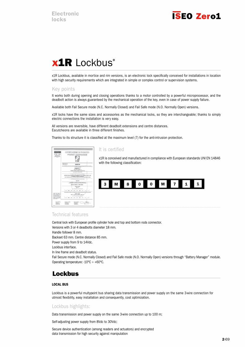
x1R Lockbus®
Lockbus
It is certified
x1R is conceived and manufactured in compliance with European standards UNI EN 14846 with the following classification:
Technical featuresCentral lock with European profile cylinder hole and top and bottom rods connector.Versions with 3 or 4 deadbolts diameter 18 mm.Handle follower 8 mm.Backset 63 mm. Centre distance 85 mm.Power supply from 9 to 14Vdc.Lockbus interface.In line frame and deadbolt status.Fail Secure mode (N.C. Normally Closed) and Fail Safe mode (N.O. Normally Open) versions through “Battery Manager” module.Operating temperature: -10°C ÷ +60°C.
x1R Lockbus, available in mortice and rim versions, is an electronic lock specifically conceived for installations in location with high security requirements which are integrated in simple or complex control or supervision systems.
It works both during opening and closing operations thanks to a motor controlled by a powerful microprocessor, and the deadbolt action is always guaranteed by the mechanical operation of the key, even in case of power supply failure.
Available both Fail Secure mode (N.C. Normally Closed) and Fail Safe mode (N.O. Normally Open) versions.
x1R locks have the same sizes and accessories as the mechanical locks, so they are interchangeable; thanks to simply electric connections the installation is very easy.
All versions are reversible, have different deadbolt extensions and centre distances.Escutcheons are available in three different finishes.
Thanks to its structure it is classified at the maximum level (7) for the anti-intrusion protection.
Key points
Electroniclocks
LoCAL buS Lockbus is a powerful multypeint bus sharing data transmission and power supply on the same 3-wire connection for utmost flexibility, easy installation and consequently, cost optimization.
Lockbus highlights: Data transmission and power supply on the same 3-wire connection up to 100 m;
Self-adjusting power supply from 8Vdc to 30Vdc;
Secure device authentication (among readers and actuators) and encrypteddata transmission for high security against manipulation
2-70
5 5
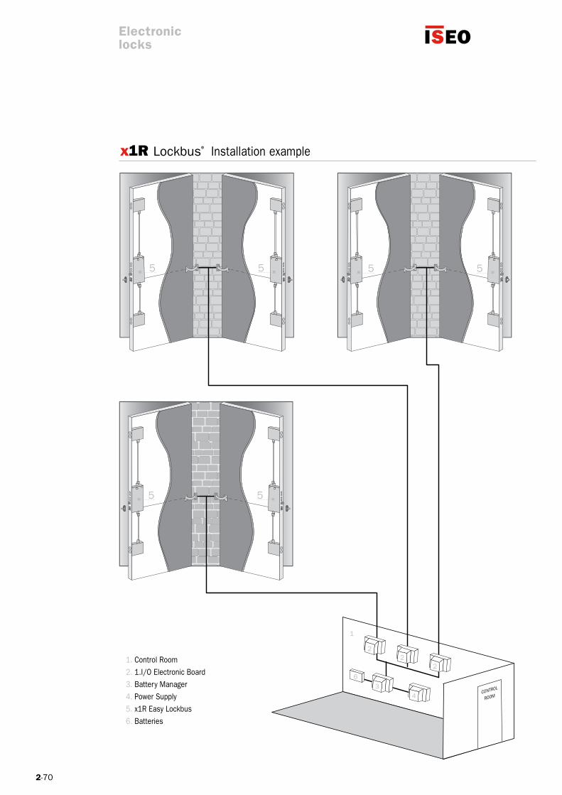
x1R Lockbus®
1
2
2
63
4
5 5
5 5
2
CONTROL
ROOM
1. Control Room2. 1.I/O Electronic Board3. Battery Manager4. Power Supply5. x1R Easy Lockbus6. Batteries
Installation example
Electroniclocks

2-71
x1R Lockbus®
x1R LOCKBUS with electronics on board. Power supply 9-14 Vdc.1,5 sec. delayed time.15 sec. courtesy time.Operating temperature: -10°C ÷ +60°C
4 DEADBOLTS. Projection 3. Centre distance 28. Lockbus. 1 00000069803281L 4 DEADBOLTS. Projection 13. Centre distance 28. Lockbus. 1 00000069813281L 3 DEADBOLTS. Projection 3. Centre distance 37. Lockbus. 1 00000069803371L 143 DEADBOLTS. Projection 13. Centre distance 37. Lockbus. 1 00000069813371L
4 DEADBOLTS. Centre distance 28. Lockbus. 1 00000069800281L 3 DEADBOLTS. Centre distance 37. Lockbus. 1 00000069800371L
Electroniclocks
Package
Code
rIM VErSIoN
MorTICE VErSIoN

2-72
x1R Lockbus®
The MULTI I/O module can manage status and opening commandsof maximum two locks x1R Lockbus through communication channel “Lockbus”.It can be programmed to operate locks x1R Lockbus in FAIL SAFE or FAIL SECURE mode. It conveys the locks’ status signals through relays (3 status per lock).It receives information from the module “Battery Manager” through an opto-isolated input.
Opto-isolated inputs 8-24 Vdc
Relay output N.O and N.C. 24Vdc/1A
Operating temperature: -10°C ÷ +60°C
Humidity max 95% without condensation
Multi I/O module 6+6 x1R Lockbus 1 5870006980014
The “Battery Manager” module charges and tests a backup battery whichsupply the necessary power to a group of locks x1R Lockbus (6 maximum)to guarantee a last emergency operation. It guarantees the operation of the locks up to 10,5V as minimum threshold in case of failure of the main power supply.It operate a periodic test (every 30 minutes) in order to convey a signaling output of the battery status. It signals also the failure of the main power supply.
Opto-isolated inputs8-24 Vdc
Relay output N.O and N.C. 24Vdc/1A
Operating temperature: -10°C ÷ +60°C
Humidity max 95% without condensation.
Modulo Battery Manager x1RL 1 5870006980015
bATTEry MANAGEr MoDuLE x1r Lockbus
MuLTI I/o MoDuLE 6+6 x1r Lockbus
Electroniclocks
Package
Code
For “Common Accessories” please see the section “Electric Locks” on pages 18 and 19
5-20
1 - Field of application These general terms of sale are intended to regulate the present and future sale contracts between the parties with the exception of any different conditions agreed in writing. Any general term established by the Buyer shall not be applied to the parties’ future relationships unless agreed in writing. The Buyer’s acceptance of FIAM’s offer or order confirmation, however made, shall imply the application of these general terms of sale to the sale contract.
2 - Information data The product features, prices and other data shown in FIAM’s catalogues, price lists or any other documents as well as the features of samples and prototypes sent to the Buyer shall not be binding unless expressly mentioned in FIAM’s offer or order confirmation.FIAM reserves the right to make any necessary changes to their products in any moment. Any technical drawing or document given to the Buyer, which allows the manufacturing or assembly of the products or their parts, is property of FIAM. It cannot be used, copied, transmitted or communicated by the Buyer to a third party unless previously agreed with FIAM.
3 - Orders Only written orders shall be accepted through an order confirmation.Any offer made by FIAM’s agents or representatives shall not be binding for FIAM until written confirmation of the latter.For single orders with an amount lower than: Italy 550,00 euroEU 1.550,00 euroNon-EU countries 3.000,00 eurothe following fixed operating expenses shall be invoiced:Italy 25,00 euroEU 78,00 euro
4 - Delivery The delivery terms are:Italy Carriage PaidEU countries Carriage PaidNon-EU countries F.O.B. (Incoterms 2000)The delivery terms are approximate in favour of FIAM with a fair tolerance margin. FIAM shall not be liable for any damage deriving from an anticipated, delayed or missing delivery, either full or partial. The risks connected to the supply shall pass on to the Buyer at the latest when the products leave FIAM’s factory, unless the sale term or the applicable regulations provide for an earlier time.
5 - Prices – PaymentsPrices, which include costs for packaging (packaging units are to be respected), shall be those in force at receipt of purchase order. Payments, as well as any other amount payable to FIAM, shall be net at their premises. The Buyer shall not be entitled to suspend payments, even in case of disputes arising from supplied products. Any payment dispute will entitle FIAM to suspend the manufacturing of the orders under execution and to ask the Buyer for suitable guarantees of payment and therefore to change the payment terms in force for future orders. No compensation with any credits towards FIAM shall be accepted.For each invoice which will not have been paid by the due date, we will calculate accrued interest on arrears, by applying the official interest rate in force, according to D.LGS N. 192/2012 - implementation of Directives 2000/35/CE and 2011/7/UE.The supplied products shall remain FIAM’s property until the full payment. To this end the Buyer shall undertake to do everything possible to grant in the Country where products are stocked a valid reservation of proprietary rights, or to put into force a warranty in favour of FIAM.
6 - Warranty No returned product shall be accepted unless previously agreed with FIAM by filling in the return authorization request form. FIAM guarantees the conformity of the products with the legislation and technical standards in force in Italy.Therefore, the buyer shall take the risk of eventual differences between Italian standards and the standards of the Country of destination of the products. FIAM guarantees the performance of their products only in relation to their stated use and application.Any other use is considered as improper.Should the Buyer resell these products, he shall be fully responsible to give his customers, at his own expenses, all the relevant information. The warranty is not valid in the following cases: products installation and/or use and/or maintenance not complying with FIAM instructions, modifications and/or repair without written authorization by FIAM, normal wear and tear.FIAM’s mechanical products are guaranteed for 10 years against any engineering, material or manufacturing failures attributable to FIAM, provided they are properly used and installed. The electronic products and door closers are guaranteed for 3 years from the date on the product label. In the absence of the label, the warranty declines unconditionally. Any replacement of components do not give rise to an extension of the warranty period for the whole product.Claims shall be made in writing, on pain of forfeiture, within 8 days from the receipt of the goods for failures relating to quantity or for failures which could be
detected by the Buyer when receiving the goods; within 8 days from the discovery of hidden failures or non-conformities. Failures shall be exclusively assessed by FIAM’s experts.No claim against FIAM shall be accepted after the expiry of the warranty period. The Buyer shall lose the warranty right if payments are not regular. This warranty is limited to the replacement of the faulty part EXW FIAM.No other reimbursement shall be made such as disassembly and assembly charges.This warranty includes and replaces any other legal warranty for failures and conformity and excludes any other liability of FIAM connected to the supplied goods. Unless in case of fraud or gross negligence grave offence on the part of FIAM, the latter shall not be liable for direct, indirect or consequential damages to the buyer of the supplied products. In particular, the Buyer shall not be entitled to claim a damage refund, a price reduction or contract termination.
7 - User Licence agreementImportant Please read carefully this end user License agreement. The installation or use of any software shown in this catalogue means that you accept the terms and conditions of the following agreement.OwnershipISEO SERRATURE S.P.A. (hereinafter ISEO), headquartered in Pisogne (BS), Via San Girolamo 13, and the productive or distribution companies of ISEO Group (hereinafter ISEO), as the only and exclusive owners, bestow the non-exclusive user license of any software contained in ISEO Zero1 product range, under the conditions described in the following paragraphs. The license is not a sale of the software and no expression contained in the license shall be construed to transfer any right or ownership.License concessionISEO grants the right to use one copy of the software on the type of computer and operating system for which the software was designed to work. ISEO recognize the rights to make backup copies only for security and archiving.Limitations on the right of useThe licensee is not authorized to rent, lease, share or to lend the software. The licensee is also not authorized to examine, modify, incorporate into another program, convert back to the original source code, decompile, disassemble or reverse engineer of the software.The licensee is not authorized to remove, change or obscure the brand Iseo or indications relating to the entitlement. ISEO shall be informed and agree on any variation of the above mentioned limitations.WarrantyISEO does not warrant that the operation of the software will be free from failures or that defects in the software will be corrected. ISEO ensures that the software is compliant with the technical and functional characteristics described in the supporting documentation. ISEO will use reasonable efforts to intervene in case of any malfunction up to 12 months after the invoice.ConfidentialityWith the acceptance of this license, the licensee agrees to use the software only within his organization and not to assign or otherwise make the software, the technical knowledge of the program and supporting documentation available to third parties. The use of the software is closely related and limited Iseo in projects and products or correlated projects if previously agreed and authorized in writing by ISEO.CopyrightThe software is the exclusive property of ISEO and is protected by Italian law on copyright, by the rules contained in international treaties and by the laws in force in the country in which it is used. Third party’s software, software tools, compilers, assemplers, debuggers, operating systems and any other software are included or used in conjunction with ISEO software. Copyright and any correlated licenses are indicated in technical manuals.Limitation of liability and exclusion of damagesIn no event will ISEO be responsible for any consequence, indirect, incidental or of any kind, including lost profits, business interruption, lost information, or other losses, arising out of the use or inability to use the software, even if ISEO has been advised on the eventuality of such damages.Iseo responsibility for any direct damages to you or any third party will be in any event limited to gross negligence or willful misconduct.
8 - Competent Court – Applicable law Any dispute arising from or connected with the contracts to which these general terms apply will be exclusively dealt with by the Court of Como; FIAM shall however be entitled to take legal action also before the Buyer’s Court. These general terms of sale are regulated by the Italian Law.
General termsof sale
0700-00473601
800-728722
Cerraduras ISEO Ibérica S.L. [email protected]
ISEO France [email protected]+33 1 64835858
ISEO Middle East [email protected]+971 4 2957220
ISEO [email protected]+8610 58698079
ISEO South Africa (Pty) [email protected]
c/o: Fiam srl - Via Don Fasola 4I-22069 Rovellasca (CO)[email protected]@iseo.com
ITALY
FRANCE
ISEO Deutschland [email protected]
GERMANY
SPAIN
ASIA
UNITED ARAB EMIRATES
SOUTh AFRICA
www. iseo .com
ISEO Serrature s.p.a.Via San Girolamo 13I-22055 Pisogne (BS)[email protected]
ISEO Asia Pacific SDN. [email protected]+603 80753331
900-126356

Cod
e 6
00
IS0
1C
00
10
0