Embed Size (px)
Citation preview

audifit 5Solutions for better hearing
User manual10/2016
2
Index
1 Introduction .......................................................................................... 3 1.1 System requirements ..................................................................................... 3
2 Fast fitting ............................................................................................. 4 2.1 Settings after starting the program for the first time ...................................... 4 2.2 Fast fitting ..................................................................................................... 4
3 User interface ........................................................................................ 8 3.1 Menu bar section ........................................................................................... 8 3.2 Fitting mode section ......................................................................................11 3.3 Navigation menu section ...............................................................................11 3.4 ToolBox/MySound! section ............................................................................ 12 3.5 Status bar section ......................................................................................... 14
4 Fitting procedure .................................................................................. 15 4.1 Client management ...................................................................................... 15 4.2 Hearing instruments ..................................................................................... 16 4.3 Presets .......................................................................................................... 17 4.4 Feedback check ............................................................................................. 18 4.5 Fitting .......................................................................................................... 20 4.6 Hearing device options .................................................................................. 31 4.7 Completion .................................................................................................. 33
5 Other program options ......................................................................... 34 5.1 Follow-up fitting .......................................................................................... 34 5.2 Exporting/importing client information ....................................................... 34 5.3 Measurement settings ................................................................................. 35
6 Troubleshooting ................................................................................... 36
7 Key to symbols ..................................................................................... 39
8 Glossary .............................................................................................. 40
3
Introduction
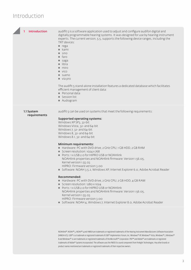
audifit 5 is a software application used to adjust and configure audifon digital and digitally programmable hearing systems. It was designed for use by hearing instrument experts. The current version, 5.5, supports the following device ranges, including the TRT devices: rega kami sino faro saga libra miro
vico sueno via pro
The audifit 5 stand-alone installation features a dedicated database which facilitates efficient management of client data: Personal data Session list Audiogram
audifit 5 can be used on systems that meet the following requirements:
Supported operating systems:Windows XP SP3, 32-bitWindows Vista, 32- and 64-bitWindows 7, 32- and 64-bitWindows 8, 32- and 64-bitWindows 8.1, 32- and 64-bit
Minimum requirements: Hardware: PC with DVD drive, 2 GHz CPU, 1 GB HDD, 2 GB RAM Screen resolution: 1024 x 768 Ports: 1 x USB 2.0 for HIPRO USB or NOAHlink NOAHlink properties and NOAHlink firmware: Version 1.56.05, Kernel version 1.55.03 HIPRO: Firmware version 3.00 Software: NOAH 3.5.2, Windows XP, Internet Explorer 6.0, Adobe Acrobat Reader
Recommended: Hardware: PC with DVD drive, 2 GHz CPU, 2 GB HDD, 4 GB RAM Screen resolution: 1280 x 1024 Ports: 1 x USB 2.0 for HIPRO USB or NOAHlink NOAHlink properties and NOAHlink firmware: Version 1.56.05, Kernel version 1.55.03 HIPRO: Firmware version 3.00 Software: NOAH 4, Windows 7, Internet Explorer 8.0, Adobe Acrobat Reader
NOAHlink™, NOAH™ 3, NOAH™ 4 and HIMSA are trademarks or registered trademarks of the Hearing Instrument Manufacturers Software Association
(HIMSA A/S). USB® is a trademark or registered trademark of USB® Implementers Forum, Inc. Windows® XP, Windows® Vista, Windows® 7, Windows®
8 and Windows® 10 are trademarks or registered trademarks of the Microsoft® Corporation. PDF™ and Adobe® are trademarks or registered
trademarks of Adobe® Systems Incorporated. The software uses the FMOD Ex sound component from Firelight Technologies. Any other brands or
product names mentioned are trademarks or registered trademarks of their respective owners.
1 Introduction
1.1 System requirements

4
Fast fitting
The next few pages outline a fast fitting procedure in brief.
After starting audifit 5 for the first time, you must set the following program options (Settings menu → Options): Enter user information (name of acoustician, etc.) Select the fitting mode, programmer box, wait screen, read protection and
languages (the fitting mode must be set to fast fitting)
The steps required to fit a hearing instrument are set out below in the quick start guide. Clicking on the appropriate button at the bottom of the screen provides a step-by-step guide for the fitting procedure. You can also go directly to the desired step by clicking on the menu item.
1. Entering client information and customer audiograms After the program begins, the client management section appears. Once a new
client has been entered or an existing client selected, the client audiogram can be entered by pressing "Add audiogram".
Continue to the next step with “Next session"
Fig. 1: Stand-alone client audiogram
2. Selecting the hearing instrument The hearing instrument is selected automatically when it is connected. If you have not yet connected the device, you can select it manually.
Continue to the next step with “Initial fitting”
Fig. 2: Automatic hearing instrument detection
2 Fast fitting
2.1 Settings after starting the program for the first time
2.2 Fast fitting

5
Fast fitting
3. Selecting the presets Once the hearing instrument has been selected, the presets "Type of fitting", "Fitting rationale" and "Acclimatisation level" should be selected:
Continue to the next step with “Fitting – First Fit”
Fig. 3: Selecting the presets
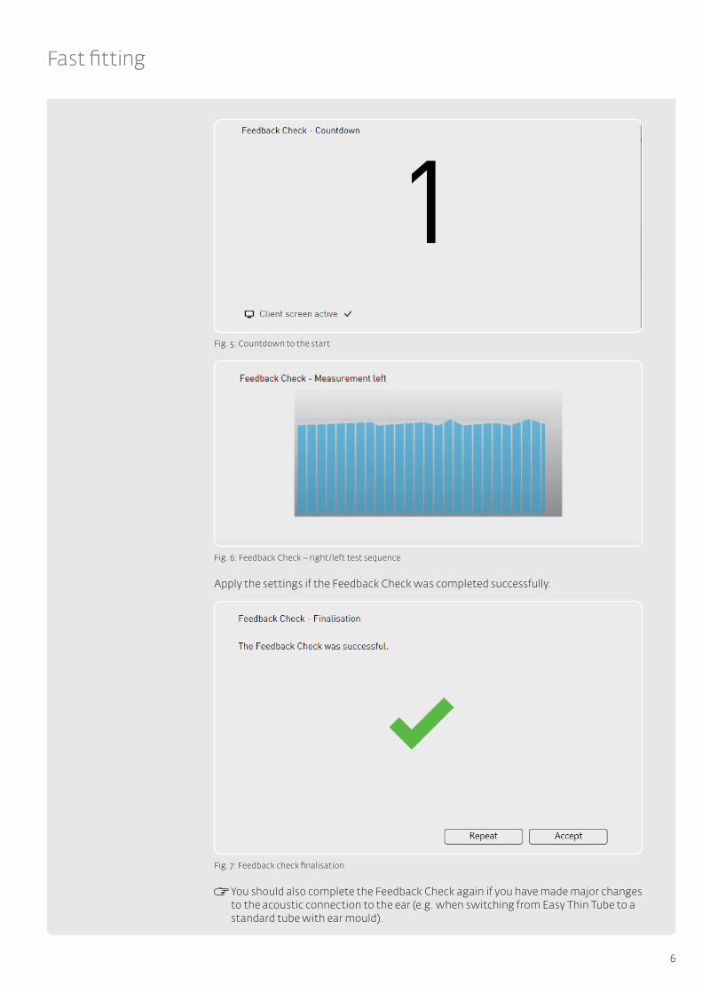
4. Feedback Check (only available on devices with the "COSMA" chip platform) The Feedback Check to initialise the Adaptive Feedback Guard is executed before the First Fit and thus individually sets the system to your client's adaptive situation. This optimises the performance of the device in relation to the stability of the gain in conjunction with the selected acoustic connection (ear mould). The duration of the initialisation only takes around ten seconds per side and should be completed at every new fitting.
Fig. 4: Feedback Check start screen
6
Fast fitting
Fig. 5: Countdown to the start
Fig. 6: Feedback Check – right/left test sequence
Apply the settings if the Feedback Check was completed successfully.
Fig. 7: Feedback check finalisation
You should also complete the Feedback Check again if you have made major changes to the acoustic connection to the ear (e.g. when switching from Easy Thin Tube to a standard tube with ear mould).
7
Fast fitting
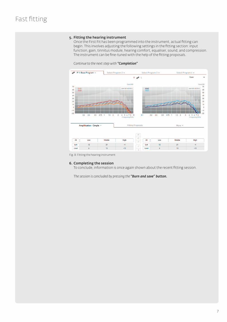
5. Fitting the hearing instrument Once the First Fit has been programmed into the instrument, actual fitting can begin. This involves adjusting the following settings in the fitting section: input function, gain, tinnitus module, hearing comfort, equaliser, sound, and compression. The instrument can be fine-tuned with the help of the fitting proposals.
Continue to the next step with “Completion”
Fig. 8: Fitting the hearing instrument
6. Completing the session To conclude, information is once again shown about the recent fitting session.
The session is concluded by pressing the “Burn and save” button.
8
User interface
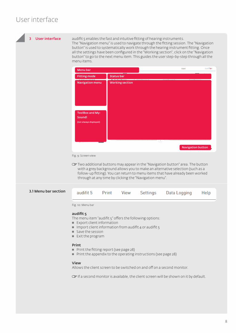
audifit 5 enables the fast and intuitive fitting of hearing instruments. The "Navigation menu" is used to navigate through the fitting session. The "Navigation button" is used to systematically work through the hearing instrument fitting. Once all the settings have been configured in the "Working section", click on the "Navigation button" to go to the next menu item. This guides the user step-by-step through all the menu items.
Fig. 9: Screen view
Two additional buttons may appear in the "Navigation button" area. The button with a grey background allows you to make an alternative selection (such as a follow-up fitting). You can return to menu items that have already been worked through at any time by clicking the "Navigation menu".
Fig. 10: Menu bar
audifit 5 The menu item "audifit 5" offers the following options: Export client information Import client information from audifit 4 or audifit 5 Save the session Exit the program
Print Print the fitting report (see page 28) Print the appendix to the operating instructions (see page 28)
View Allows the client screen to be switched on and off on a second monitor.
If a second monitor is available, the client screen will be shown on it by default.
3 User interface
3.1 Menu bar section
Menu bar
Fitting mode Status bar
Working sectionNavigation menu
ToolBox and My-
Sound!
(not always displayed)
Navigation button

9
User interface
SettingsProgram options are accessed in the menu bar under "Settings" → "Options". The following settings are available: Fitting Calibration (MySound!) User information
The hearing instruments can be set to maximum test gain under "Measurement settings" (see 5.3).
Warning: Damage to hearing! The instruments are set to the maximum test gain for measuring purposes. The hearing instrument must not be near the client’s ear at this setting! Otherwise there is a risk of damaging the residual hearing.
9 Fitting The following settings are available under "Fitting":
Select default fitting mode Programmer box selection Wait screen Security (read protection) Language
Fig. 11: Program options for fitting
Fitting mode Allows selection of standard fitting or fast fitting. If fast fitting mode is selected, the "Presets" and "HI options" menu items will be skipped during the procedure (via the navigation buttons). The "Fitting" menu item also has an optimised layout. You can, however, go to the skipped sections by clicking directly on the menu item. The fitting mode can be changed at any time in the drop-down menu above the menu items.
Programmer box selection Select the programmer box to be used (such as HI-PRO or NOAHlink).
Wait screen Allows selection of a logo that (if available) appears on the client screen during
the fitting.

10
User interface
Security Allows activation or deactivation of readout protection for the hearing
instrument. If read protection is to be used for all fittings, a PIN code can be entered here.
Language Select the language for software, client screen and sound examples.The client
screen appears in the client’s language, while the fitting software appears in the language of the acoustician. The appendix to the operating instructions is printed out in the client’s language. The sound examples are played back in the client’s language.
9 Calibration Allows calibration of the 5.0-channel MySound! system with any sound level meter. This means that a noise can be played back for each of the five speakers.
Fig. 12: Calibration of the MySound! system
9 User information Enter the name and address of the acoustician and select a logo.
Fig. 13: Entering user information
Data loggingThe data logging function records the client’s usage behaviour. The recorded data can be displayed and read out by clicking on "Data logging" in the menu bar: Display recorded data (shows the data read out from a previously saved session) Read out recorded data (reads out and displays data from a connected hearing
instrument)
The graph of the recorded data contains information about the duration of usage, duration of use per program, and Sound Dynamix.
11
User interface
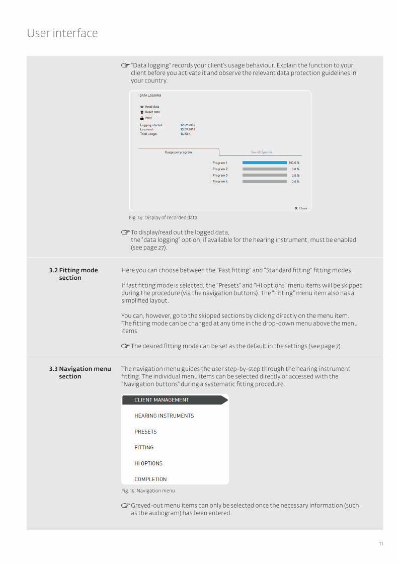
"Data logging" records your client’s usage behaviour. Explain the function to your client before you activate it and observe the relevant data protection guidelines in your country.
Fig. 14: Display of recorded data
To display/read out the logged data, the “data logging” option, if available for the hearing instrument, must be enabled (see page 27).
Here you can choose between the "Fast fitting" and "Standard fitting" fitting modes.
If fast fitting mode is selected, the "Presets" and "HI options" menu items will be skipped during the procedure (via the navigation buttons). The "Fitting" menu item also has a simplified layout.
You can, however, go to the skipped sections by clicking directly on the menu item. The fitting mode can be changed at any time in the drop-down menu above the menu items.
The desired fitting mode can be set as the default in the settings (see page 7).
The navigation menu guides the user step-by-step through the hearing instrument fitting. The individual menu items can be selected directly or accessed with the "Navigation buttons" during a systematic fitting procedure.
Fig. 15: Navigation menu
Greyed-out menu items can only be selected once the necessary information (such as the audiogram) has been entered.
3.2 Fitting mode section
3.3 Navigation menu section
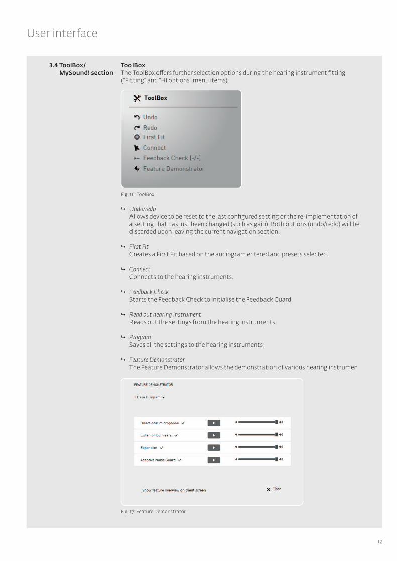
Fig. 17: Feature Demonstrator
12
User interface
ToolBoxThe ToolBox offers further selection options during the hearing instrument fitting ("Fitting" and "HI options" menu items):
Fig. 16: ToolBox
9 Undo/redo Allows device to be reset to the last configured setting or the re-implementation of a setting that has just been changed (such as gain). Both options (undo/redo) will be discarded upon leaving the current navigation section.
9 First Fit Creates a First Fit based on the audiogram entered and presets selected.
9 Connect Connects to the hearing instruments.
9 Feedback Check Starts the Feedback Check to initialise the Feedback Guard.
9 Read out hearing instrument Reads out the settings from the hearing instruments.
9 Program Saves all the settings to the hearing instruments
9 Feature Demonstrator The Feature Demonstrator allows the demonstration of various hearing instrumen
3.4 ToolBox/MySound! section
13
User interface
The steps below summarise the use of the Feature Demonstrator: Select the hearing instrument program in which the feature is to be demonstrated Select the active hearing instrument features by clicking on the feature Play back the sound example by clicking on the play button of the desired feature The nature of the sound examples changes over time. It is therefore recommended
that the sounds are played in their entirety. During sound playback, the client can activate/deactivate the feature himself on the
client screen and experience its effect.
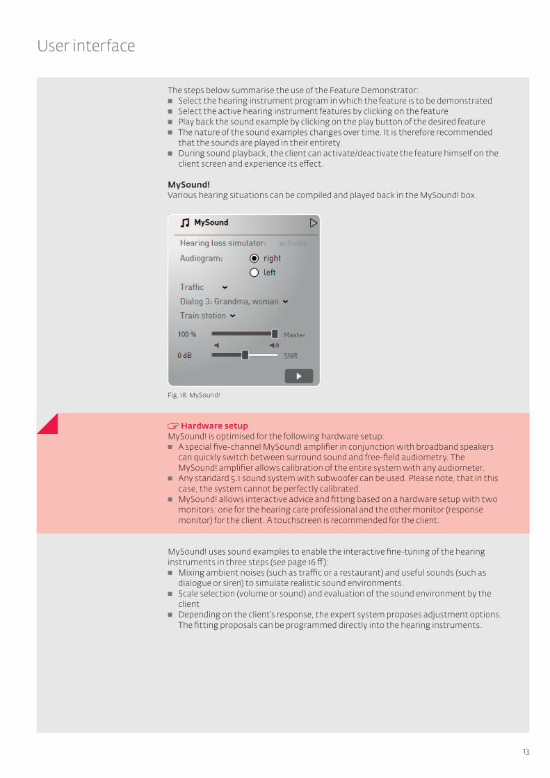
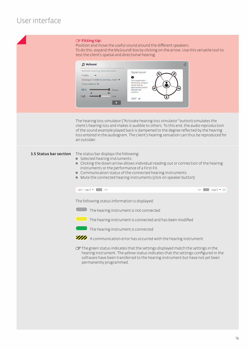
MySound!Various hearing situations can be compiled and played back in the MySound! box.
Fig. 18: MySound!
Hardware setupMySound! is optimised for the following hardware setup: A special five-channel MySound! amplifier in conjunction with broadband speakers
can quickly switch between surround sound and free-field audiometry. The MySound! amplifier allows calibration of the entire system with any audiometer.
Any standard 5.1 sound system with subwoofer can be used. Please note, that in this case, the system cannot be perfectly calibrated.
MySound! allows interactive advice and fitting based on a hardware setup with two monitors: one for the hearing care professional and the other monitor (response monitor) for the client. A touchscreen is recommended for the client.
MySound! uses sound examples to enable the interactive fine-tuning of the hearing instruments in three steps (see page 16 ff ): Mixing ambient noises (such as traffic or a restaurant) and useful sounds (such as
dialogue or siren) to simulate realistic sound environments. Scale selection (volume or sound) and evaluation of the sound environment by the
client Depending on the client’s response, the expert system proposes adjustment options.
The fitting proposals can be programmed directly into the hearing instruments.
14
User interface
Fitting tip:Position and move the useful sound around the different speakers. To do this, expand the MySound! box by clicking on the arrow. Use this versatile tool to test the client’s spatial and directional hearing.
The hearing loss simulator ("Activate hearing loss simulator" button) simulates the client’s hearing loss and makes it audible to others. To this end, the audio reproduction of the sound example played back is dampened to the degree reflected by the hearing loss entered in the audiogram. The client’s hearing sensation can thus be reproduced for an outsider.
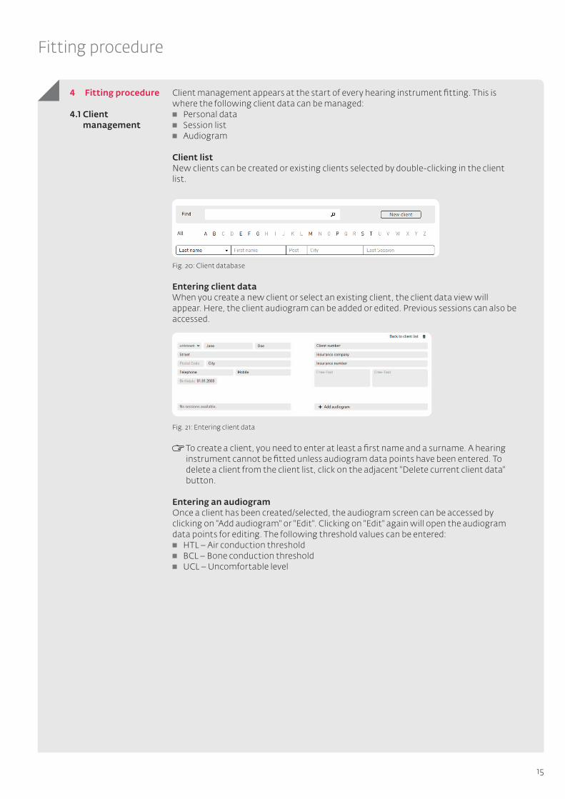
The status bar displays the following: Selected hearing instruments Clicking the down arrow allows individual reading out or connection of the hearing
instruments or the performance of a First Fit. Communication status of the connected hearing instruments Mute the connected hearing instruments (click on speaker button)
The following status information is displayed: The hearing instrument is not connected The hearing instrument is connected and has been modified The hearing instrument is connected A communication error has occurred with the hearing instrument
The green status indicates that the settings displayed match the settings in the hearing instrument. The yellow status indicates that the settings configured in the software have been transferred to the hearing instrument but have not yet been permanently programmed.
3.5 Status bar section
15
Fitting procedure
Client management appears at the start of every hearing instrument fitting. This is where the following client data can be managed: Personal data Session list Audiogram
Client listNew clients can be created or existing clients selected by double-clicking in the client list.
Fig. 20: Client database
Entering client dataWhen you create a new client or select an existing client, the client data view will appear. Here, the client audiogram can be added or edited. Previous sessions can also be accessed.
Fig. 21: Entering client data
To create a client, you need to enter at least a first name and a surname. A hearing instrument cannot be fitted unless audiogram data points have been entered. To delete a client from the client list, click on the adjacent "Delete current client data" button.
Entering an audiogramOnce a client has been created/selected, the audiogram screen can be accessed by clicking on "Add audiogram" or "Edit". Clicking on "Edit" again will open the audiogram data points for editing. The following threshold values can be entered: HTL – Air conduction threshold BCL – Bone conduction threshold UCL – Uncomfortable level
4 Fitting procedure
4.1 Client management

16
Fitting procedure
Fig. 22: Entering audiogram data points
Additional data that can be entered: "Set HTL equal to BCL" – sets the air conduction threshold equal to the bone
conduction threshold "Copy to left/right" – copies the audiogram from the other side "Clear selected audiogram curve" – deletes the selected curve only "Delete all audiogram curves" – deletes the audiogram data points entered
Once audiogram data point entry is complete, continue to the next step by clicking the "Next session" button or enter client data with "Back to client". Either way, the audiogram data points entered will be saved.
The hearing instruments used for the fitting must be selected. This can be done automatically (for both / just right / just left) or manually.
Fig. 23: Detecting the hearing instrument
Warning: Damage to hearing!The hearing instrument is not yet set for the client at the initial fitting. The hearing instrument must not be placed to the client’s ear until after the First Fit! Otherwise there is a risk of damaging the residual hearing.
Automatic hearing instrument detectionTo automatically select the hearing instruments, connect them using a suitable programming cable. The detected hearing instruments will be displayed with the serial numbers for the respective side (right/left).
4.2 Hearing instruments
17
Fitting procedure
RITE hearing instruments (Receiver In The Ear) Receiver unit S is the default setting for RITE hearing instruments. If another type of receiver unit is used, select it in the next step, "Presets". The follow-up fitting for new sessions is taken on by the receiver unit from the connected device.
CROS/BiCROS hearing instruments The receiver (Rx) and transmitter (Tx) must always be combined for CROS/BiCROS hearing instruments.
Selecting hearing instruments manuallyAlternatively, the hearing instruments can be selected manually. To do so, select the desired hearing instruments.
RITE hearing instruments (Receiver In The Ear) For RITE hearing instruments, also select the receiver unit used.
CROS/BiCROS hearing instruments For CROS/BiCROS hearing instruments, always select the receiver (Rx) and transmitter (Tx). The selection is supported by a selection assistant.
Further informationAfter the hearing instruments have been selected, the following information about them is available: Data specification Fitting range (with air conduction audiogram) Features Colour options
If the fitting range area is shaded, the fitting range refers to devices with open fitting.
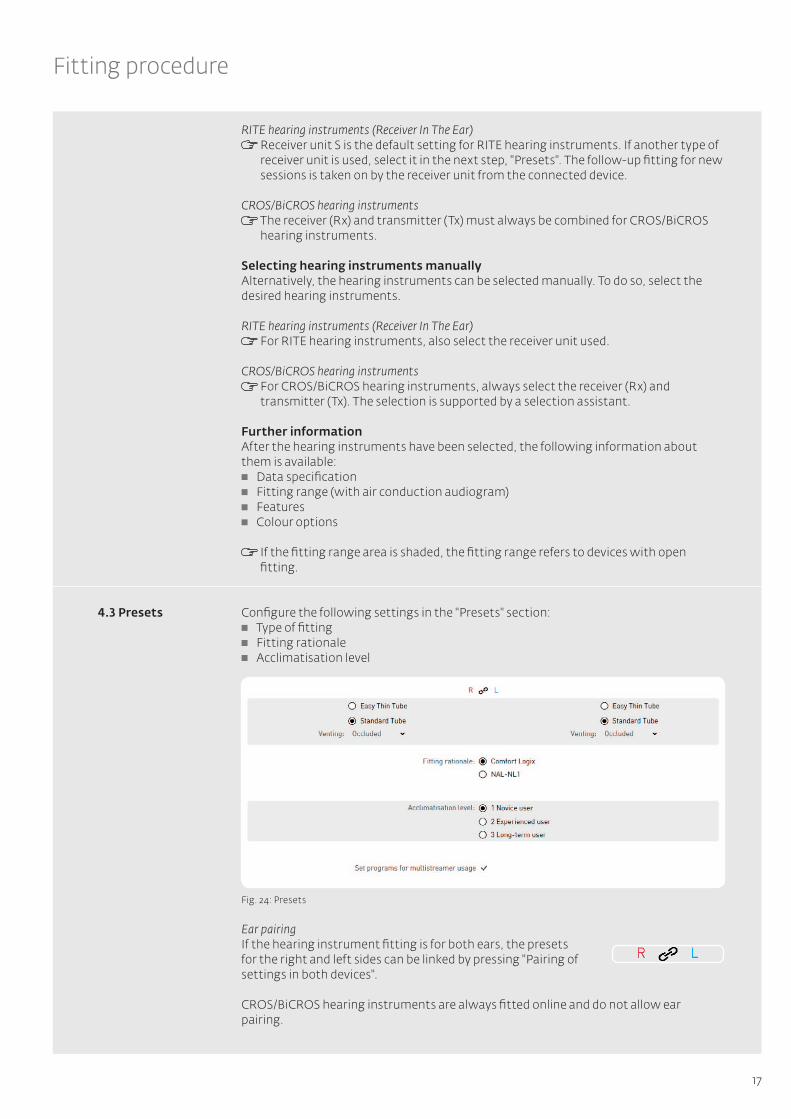
Configure the following settings in the "Presets" section: Type of fitting Fitting rationale Acclimatisation level
Fig. 24: Presets
Ear pairingIf the hearing instrument fitting is for both ears, the presets for the right and left sides can be linked by pressing "Pairing of settings in both devices". CROS/BiCROS hearing instruments are always fitted online and do not allow ear pairing.
4.3 Presets
18
Fitting procedure
Type of fittingDepending on the hearing instrument selected, various fitting options are available:
9 Fitting BTE hearing instruments Closed fitting (with ear mould):
If an ear mould is used for the fitting, select the closed fitting and specify the vent diameter.
Easy Thin Tube (open fitting with thin sound tube): If an open fitting with thin sound tube is used, select the sound tube and dome size.
9 Fitting ITE hearing instruments Only the vent diameter must be specified for ITE hearing instruments.
If the vent diameter is greater than 3 mm, select "open".
9 Fitting RITE (Receiver In The Ear) hearing instruments For RITE hearing instruments, select the receiver unit used and its length and dome
size.
9 Fitting hearing instruments with the multistreamer accessory For hearing instruments with the multistreamer accessory, the programs for its
use can be automatically preset. This entails setting all possible programs to the determined hearing situations.
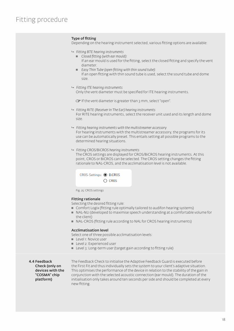
9 Fitting CROS/BiCROS hearing instruments The CROS settings are displayed for CROS/BiCROS hearing instruments. At this
point, CROS or BiCROS can be selected. The CROS setting changes the fitting rationale to NAL-CROS, and the acclimatisation level is not available.
Fig. 25: CROS settings
Fitting rationale Selecting the desired fitting rule: Comfort Logix (fitting rule optimally tailored to audifon hearing systems) NAL-NL1 (developed to maximise speech understanding at a comfortable volume for
the client) NAL-CROS (fitting rule according to NAL for CROS hearing instruments)
Acclimatisation levelSelect one of three possible acclimatisation levels: Level 1: Novice user Level 2: Experienced user Level 3: Long-term user (target gain according to fitting rule)
The Feedback Check to initialise the Adaptive Feedback Guard is executed before the First Fit and thus individually sets the system to your client's adaptive situation. This optimises the performance of the device in relation to the stability of the gain in conjunction with the selected acoustic connection (ear mould). The duration of the initialisation only takes around ten seconds per side and should be completed at every new fitting.
4.4 Feedback Check (only on devices with the "COSMA" chip platform)

19
Fitting procedure
Fig. 26: Feedback Check start screen
Before starting the Feedback Check near the client’s ear, ensure that the device fits perfectly.
Fig. 27: Countdown to the start
Fig. 28: Feedback Check – right/left test sequence
Apply the settings if the Feedback Check was completed successfully.

20
Fitting procedure
4.5 Fitting
Fig. 29: Feedback check finalisation
You should also complete the Feedback Check again if you have made major changes to the acoustic connection to the ear (e.g. when switching from Easy Thin Tube to a standard tube with ear mould).
The following settings can be configured for the hearing instrument’s individual programs in the "Fitting" section: Input function Gain Noise Hearing comfort Equaliser Sound Compression It is also possible to interactively fine-tune the instrument under "Fitting proposals".
Fig. 30: Overview of the "Fitting" section
The ToolBox and MySound! sections are shown on the left side of the screen during the fitting. The method of displaying the curves can be selected from the drop-down menu in the top right-hand corner.

21
Fitting procedure
Ear pairingIf the hearing instrument fitting is for both ears, the fitting settings for the right and left side can be linked by pressing "Pair settings on both sides". CROS/BiCROS hearing instruments are always fitted online and do not allow ear pairing.
Program couplingThe settings made in Program 1 (basic program) are transferred to all other programs with the active button.
Program selectionThe individual programs can be selected below the status bar. A click on a given program opens a drop-down menu from which the desired hearing program (such as "Speech in noise" or "Phone") can be selected.
The following preset hearing programs are available: Speech in noise: Focuses on speech intelligibility. Speech is retained while
background noise is reduced. Music: Sound-optimised program for playing back music Comfort in noise: Reduces the output for loud input level reduces the gain over the
entire frequency range for added hearing comfort in noisy environments.
Telephone: Program optimised for the telephone (activates available telephone loop and microphone)
4, 6, 8, 12, and 18 dB lower: Lowers the gain compared to the basic program.
The following hearing programs are also available for tinnitus devices in the "Tinnitus module" input: Noise combi program: A combined signal (hearing instrument signal and white
noise) is produced to correct the hearing loss and to support tinnitus therapy. Only noise: Only noise is produced.
Faro Program options (only with faro selected as the hearing system) Faro hearing systems are configured to receive audio signals via multistreamer in
Program 3. Two options are available in Program 4: Auto T-Coil/Autophone mode or wireless
phone streaming (managing phone calls on telephones linked via multistreamer). If the "Binaural T-Coil" hearing situation is selected, "Binaural T-Coil" and "Binaural T-Coil + Microphone" are available as signal sources in Program 4. In these modes, the signal received via the T-Coil is transmitted to the second hearing system so that the signal is audible on both sides.
The following hearing programs can be selected in Program 4 for hearing instruments with the Auto T-Coil or Auto-Phone function: Auto T-Coil: When a telephone receiver is held to the ear, the instrument
automatically switches to Program 4 – telephone loop and microphone are activated.
Auto Phone: When a telephone receiver is held to the ear, the instrument automatically switches to Program 4 – a telephone-optimised microphone program is activated.
Once the phone call is over (receiver is moved away from ear) the instrument switches back to the last program in use.

22
Fitting procedure
Fitting tip: Hearing instruments with just one program switch
If the hearing instrument has just one program switch, the programs available for volume control can be used. To do this, select "Program switch as VC" from the drop-down menu of Program 1.
Input function Depending on the type of hearing instrument, the desired input function for the selected program can be set: Microphone Directional microphone Line-in Line-in and microphone Adaptive directional microphone Sound Dynamix (including control rate) Scene Detect Binaural T-Coil Binaural T-Coil and microphone
Fig. 31: Input function
9 Hearing instruments with Sound Dynamix If the hearing instrument has Sound Dynamix (automatic program toggle), it can
be activated as an input function. The hearing instrument will then automatically distinguish between quiet, speech in a quiet setting, noise, speech in a noisy setting, music, and wind. The time it takes to switch programs can be regulated in increments of 5, 10, and 20 seconds. In the individual programs that Sound Dynamix selects, the directional microphones, noise reduction, feedback suppression, and gain are affected.
9 Hearing instruments with Scene Detect The hearing instruments uses Scene Detect to classify the input signal into seven
different categories: Quiet, wind, machine noise, music, speech in a quiet setting, speech in a noisy setting and other noise. Depending on the classification, the settings for the Adaptive Feedback Guard, Adaptive Noise Guard, Machine Noise Guard and Wind Shield are automatically optimised for the hearing situation detected in each case (see 4.5.6. for description of the individual features). A special gain setting is also implemented for the music input signal.
23
Fitting procedure
9 Wireless hearing instruments with binaural telephony For hearing instruments with binaural telephony, which are selected in Auto-
Program/Program 4, the input function options for the T-Coil are with and without microphone.
9 CROS/BiCROS hearing instruments For CROS/BiCROS hearing instruments, the input function is only available on the
receiver (Rx) side. In CROS mode, only the microphone is available and always active.
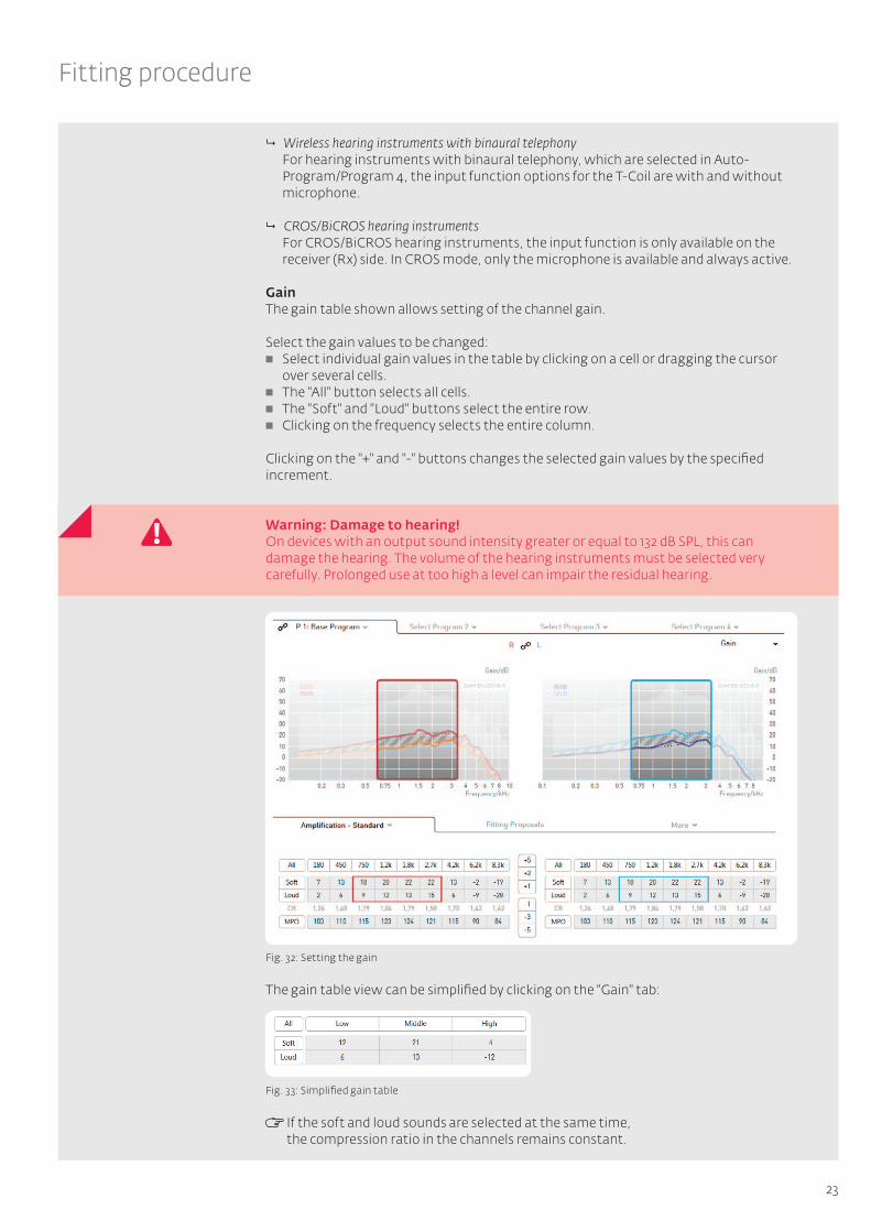
GainThe gain table shown allows setting of the channel gain.
Select the gain values to be changed: Select individual gain values in the table by clicking on a cell or dragging the cursor
over several cells. The "All" button selects all cells. The "Soft" and "Loud" buttons select the entire row. Clicking on the frequency selects the entire column.
Clicking on the "+" and "-" buttons changes the selected gain values by the specified increment.
Warning: Damage to hearing!On devices with an output sound intensity greater or equal to 132 dB SPL, this can damage the hearing. The volume of the hearing instruments must be selected very carefully. Prolonged use at too high a level can impair the residual hearing.
Fig. 32: Setting the gain
The gain table view can be simplified by clicking on the "Gain" tab:
Fig. 33: Simplified gain table
If the soft and loud sounds are selected at the same time, the compression ratio in the channels remains constant.
24
Fitting procedure
If the gains are set either just for soft or just for loud sounds, the compression ratio is adjusted automatically. The higher (lower) the displayed compression ratio is, the more (less) the input signal is compressed.
Compression is used when the natural dynamic range has to be limited to the client’s residual dynamic range.
The MPO (Maximum Power Output) limits the output sound pressure level of the hearing system. Sound pressure levels that exceed the set threshold are reduced in the gain. The MPO should be set according to the client’s uncomfortable level.
If the audiogram contains uncomfortable threshold values, the AGCo threshold is automatically set by First Fit.
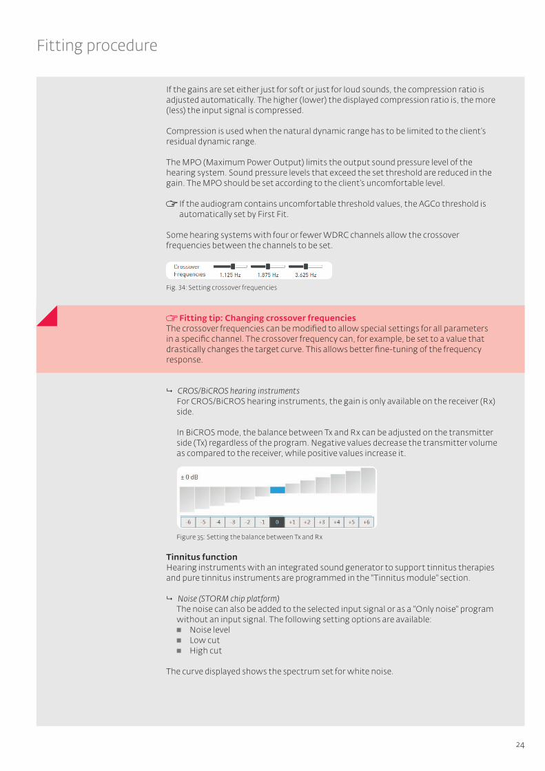
Some hearing systems with four or fewer WDRC channels allow the crossover frequencies between the channels to be set.
Fitting tip: Changing crossover frequenciesThe crossover frequencies can be modified to allow special settings for all parameters in a specific channel. The crossover frequency can, for example, be set to a value that drastically changes the target curve. This allows better fine-tuning of the frequency response.
9 CROS/BiCROS hearing instruments For CROS/BiCROS hearing instruments, the gain is only available on the receiver (Rx)
side.
In BiCROS mode, the balance between Tx and Rx can be adjusted on the transmitter side (Tx) regardless of the program. Negative values decrease the transmitter volume as compared to the receiver, while positive values increase it.
Figure 35: Setting the balance between Tx and Rx
Tinnitus functionHearing instruments with an integrated sound generator to support tinnitus therapies and pure tinnitus instruments are programmed in the "Tinnitus module" section.
9 Noise (STORM chip platform) The noise can also be added to the selected input signal or as a "Only noise" program
without an input signal. The following setting options are available: Noise level Low cut High cut
The curve displayed shows the spectrum set for white noise.
Fig. 34: Setting crossover frequencies

25
Fitting procedure
Fig. 36: Noise level settings
9 Tinnitus module (COSMA chip platform) In hearing instruments with the COSMA chip platform, noise levels can be set
independently for the tinnitus in new channels via the gain table. There is also an option to choose between three different pre-defined noise types:
White noise: Noise with the same sound pressure level in all frequency bands Pink noise: Noise with frequencies that are too high at a decreasing level Sound of the sea: A noise for which the volume swells and subsides (fluctuates)
and that simulates the characteristic noise of the ocean. The speed of the fluctuation can be set in three stages via the "Modulation" drop-down menu
The sound and volume of the noise can be adjusted to the individual requirements of your client from the outset or based on the three noise types mentioned above.
Figure 37: COSMA noise level settings
Warning: Damage to hearing! The noise level should not exceed 74 dB SPL. Higher noise levels can cause the residual hearing to deteriorate in the long run.
Hearing comfortThe hearing comfort section provides the following options for reducing background noise and feedback: Adaptive ambient noise reduction (ANR) Expansion Adaptive feedback cancellation (AFC) Notch filter

26
Fitting procedure
Figure 38: Hearing comfort
9 Adaptive Noise Reduction (ANR) Adaptive ambient noise reduction (ANR) automatically lowers the gain in the
frequency bands with the poorest signal-to-noise ratio. ANR is particularly effective when the client is dependent on good speech understanding in an acoustic environment with a wide range of background noise. You can choose from three different ANR settings:
Soft: The gain is reduced by approx. 3-4 dB per band. This setting is used to obtain maximum speech quality.
Moderate: The gain is reduced by approx. 6-7 dB per band.
Strong: The gain is reduced by approx. 9-10 dB per band. This setting is used to minimise background noise.
9 Expansion The expansion (squelch) reduces the audibility of soft background noise such as
air conditioning or computers. The expansion also reduces noises caused by the components of the actual hearing instrument, primarily by the microphone. Clients with normal hearing in the low frequency range can find the inherent noise especially annoying.
In order to activate the expansion in a soft acoustic environment, a threshold value is specified for the input signal. The gain is reduced as soon as the signal falls below this value, reducing the audibility of the microphone noise and improving sound quality. Above the threshold value, the hearing instrument returns to normal gain. The default setting for the expansion threshold is preset to 40 dB SPL.
9 Adaptive Feedback Cancellation (AFC) Adaptive feedback cancellation (AFC) estimates the proportion of the signal
attributable to feedback and automatically eliminates it. AFC does not reduce the gain. Adaptive feedback cancellation is especially important for open fittings. AFC can be switched on and off.
AFC² contains an improved and more detailed model of the feedback path, allowing more accurate feedback elimination. This makes even higher gains possible before feedback occurs (known as “added stable gain”).
The hearing instrument consumes more energy when the AFC/AFC² algorithm is used.

27
Fitting procedure
9 Notch filter Unlike AFC, a notch filter reduces the gain in a certain narrow frequency range to
prevent feedback. The notch filter can therefore reduce sound quality. The digital notch filter can be programmed so that its centre frequency lowers the gain of the critical frequency causing the feedback.
The amount by which the gain can be reduced is between 2 and 16 dB. Clicking on the adjacent button selects the frequency at which the notch filter’s centre frequency is to be positioned. The width of the notch filter can be defined between one octave for a wide band and 1/12 of an octave for a very narrow band. The notch filter changes the frequency response of the hearing instrument, resulting in poorer audibility in the corresponding frequency range.
Hearing comfort (on devices with the "COSMA" chip platform)
Figure 39: COSMA hearing comfort
9 Adaptive Noise Guard The noise reduction on devices with the "COSMA" chip platform continuously
estimates the SNR of the input signal on all available channels. If a poor value is detected on one of the channels, the channel gain is temporarily reduced to minimise the impact of the noise. The higher the proportion of the noise, the more the gain is reduced. This makes it possible for speech within the noise to be understood at low concentration levels. At the same time, the adaptive noise guard also effectively suppresses any disruptive noise in simple noise situations.
Moderate; client profile Will rarely be in very noisy hearing situations Wants natural sound and minimal audible controls
Strong; client profile Frequently in very noisy hearing situations Wants to improve understanding of speech in these situations
Use "moderate" as the default setting in the basic program, and the "strong" setting in a separate hearing program for comfort or language during disruptive noise.
9 Expansion The expansion enables you to reliably suppress any noise generated by the
microphone without affecting important signals and to remove any quiet background noise, such as the noise of a fan on the work or home computer, from the surrounding area. The setting levels consist of three different control times ranging from 10 ms to 500 ms with which you can react to your client's individual sound sensitivity.

28
Fitting procedure
9 Adaptive Feedback Guard The Adaptive Feedback Guard permanently estimates the feedback path, so that it
can also react to changing situations and any uncomfortable feedback is avoided. The Adaptive Feedback Guard should always be switched on to ensure that there is no feedback noise even in acoustically difficult situations (brushing hair aside, hat, close to a doorframe). A special mode has been developed to listen to music, it reacts more gently and is thus optimised to the special requirements for suppressing the feedback of the music input signal. Setting levels: fast and slow
Always leave the Adaptive Feedback Guard switched on and use the "slow" setting in any hearing program for music.
9 Wind Shield If the person wearing the hearing instrument is in a windy environment, turbulence
at the microphone openings can cause rustling background noises. Wind Shield recognises these and reacts by temporarily reducing the gain in the corresponding frequency range.
Always leave Wind Shield activated. Due to the automatic control, it is only implemented when the client is actually in a corresponding situation.
9 Machine Noise Guard The instruments from the rega range automatically classify the relevant hearing
situation that the client is in. If any machine noise is detected, the instrument temporarily reduces the gain for low frequencies to minimise the noise pollution.
MySound! noise example for demonstration purposes: Traffic noise
Always leave the Machine Noise Guard activated. Due to the automatic control, it is only implemented when the client is actually in a correspondingly classified hearing situation.
29
Fitting procedure
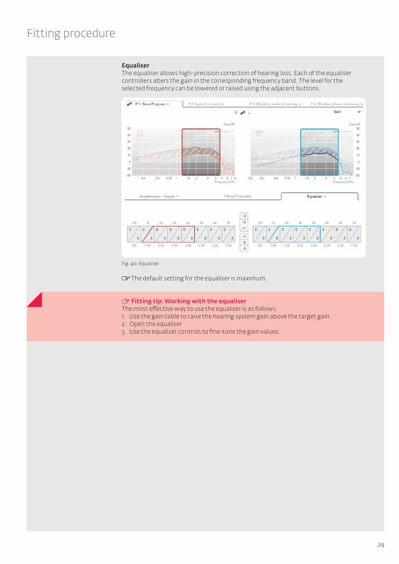
EqualiserThe equaliser allows high-precision correction of hearing loss. Each of the equaliser controllers alters the gain in the corresponding frequency band. The level for the selected frequency can be lowered or raised using the adjacent buttons.
Fig. 40: Equaliser
The default setting for the equaliser is maximum.
Fitting tip: Working with the equaliserThe most effective way to use the equaliser is as follows: 1. Use the gain table to raise the hearing system gain above the target gain.2. Open the equaliser3. Use the equaliser controls to fine-tune the gain values.
30
Fitting procedure
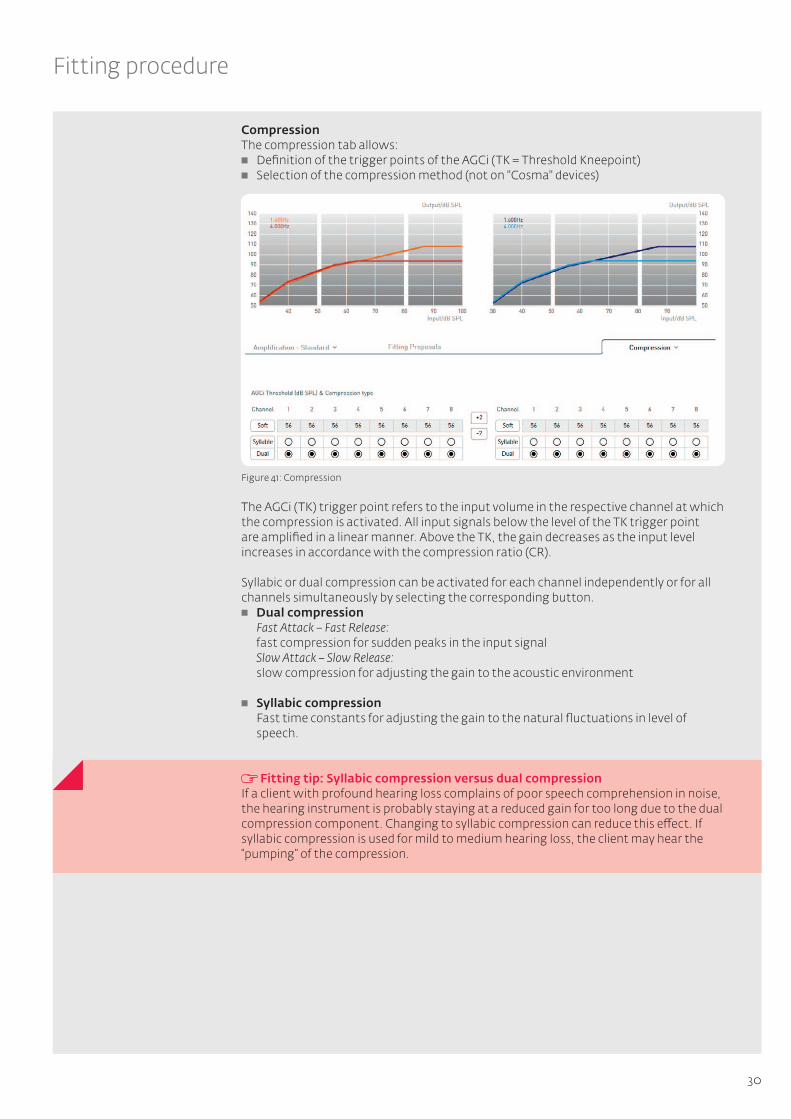
CompressionThe compression tab allows: Definition of the trigger points of the AGCi (TK = Threshold Kneepoint) Selection of the compression method (not on "Cosma" devices)
Figure 41: Compression
The AGCi (TK) trigger point refers to the input volume in the respective channel at which the compression is activated. All input signals below the level of the TK trigger point are amplified in a linear manner. Above the TK, the gain decreases as the input level increases in accordance with the compression ratio (CR).
Syllabic or dual compression can be activated for each channel independently or for all channels simultaneously by selecting the corresponding button. Dual compression
Fast Attack – Fast Release: fast compression for sudden peaks in the input signal Slow Attack – Slow Release: slow compression for adjusting the gain to the acoustic environment
Syllabic compression Fast time constants for adjusting the gain to the natural fluctuations in level of speech.
Fitting tip: Syllabic compression versus dual compressionIf a client with profound hearing loss complains of poor speech comprehension in noise, the hearing instrument is probably staying at a reduced gain for too long due to the dual compression component. Changing to syllabic compression can reduce this effect. If syllabic compression is used for mild to medium hearing loss, the client may hear the “pumping” of the compression.
31
Fitting procedure
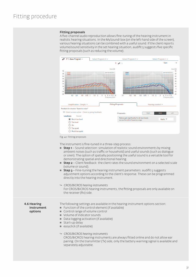
Fitting proposalsA five-channel audio reproduction allows fine-tuning of the hearing instrument in realistic hearing situations. In the MySound! box (on the left-hand side of the screen), various hearing situations can be combined with a useful sound. If the client reports volume/sound sensitivity in the set hearing situation, audifit 5 suggests five specific fitting proposals (such as reducing the volume).
Fig. 42: Fitting proposals
The instrument is fine-tuned in a three-step process: Step 1 – Sound selection: simulation of realistic sound environments by mixing
ambient noises (such as traffic or household) and useful sounds (such as dialogue or siren). The option of spatially positioning the useful sound is a versatile tool for demonstrating spatial and directional hearing.
Step 2 – Client feedback: the client rates the sound environment on a selected scale (volume or sound).
Step 3 – Fine-tuning the hearing instrument parameters: audifit 5 suggests adjustment options according to the client’s response. These can be programmed directly into the hearing instrument.
9 CROS/BiCROS hearing instruments For CROS/BiCROS hearing instruments, the fitting proposals are only available on
the receiver (Rx) side.
4.6 Hearing instrument options
The following settings are available in the hearing instrument options section: Function of the control element (if available) Control range of volume control Volume of indicator sounds Data logging activation (if available) Start-up delay easyclick (if available)
9 CROS/BiCROS hearing instruments CROS/BiCROS hearing instruments are always fitted online and do not allow ear
pairing. On the transmitter (Tx) side, only the battery warning signal is available and separately adjustable.
32
Fitting procedure
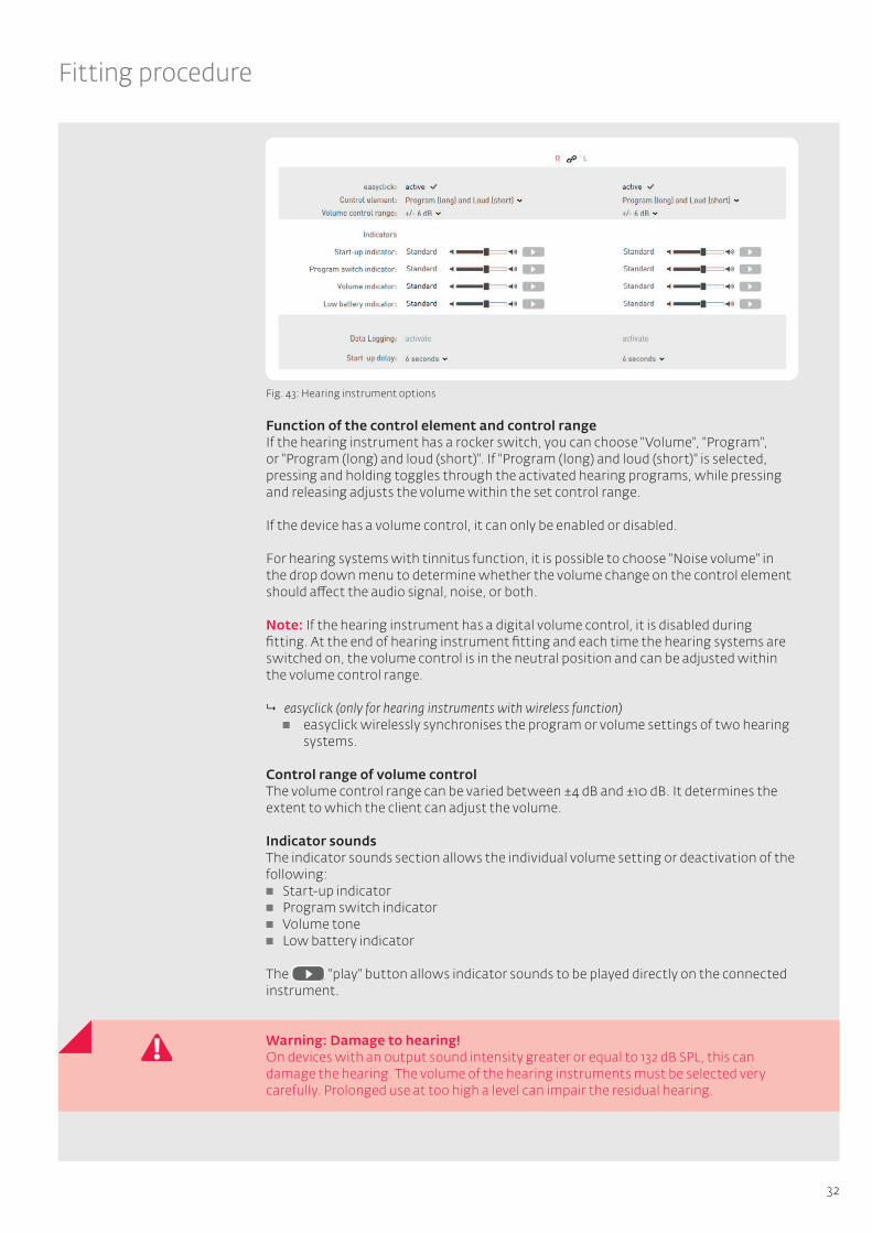
Fig. 43: Hearing instrument options
Function of the control element and control rangeIf the hearing instrument has a rocker switch, you can choose "Volume", "Program", or "Program (long) and loud (short)". If "Program (long) and loud (short)" is selected, pressing and holding toggles through the activated hearing programs, while pressing and releasing adjusts the volume within the set control range.
If the device has a volume control, it can only be enabled or disabled.
For hearing systems with tinnitus function, it is possible to choose "Noise volume" in the drop down menu to determine whether the volume change on the control element should affect the audio signal, noise, or both.
Note: If the hearing instrument has a digital volume control, it is disabled during fitting. At the end of hearing instrument fitting and each time the hearing systems are switched on, the volume control is in the neutral position and can be adjusted within the volume control range.
9 easyclick (only for hearing instruments with wireless function) easyclick wirelessly synchronises the program or volume settings of two hearing
systems.
Control range of volume controlThe volume control range can be varied between ±4 dB and ±10 dB. It determines the extent to which the client can adjust the volume.
Indicator soundsThe indicator sounds section allows the individual volume setting or deactivation of the following: Start-up indicator Program switch indicator Volume tone Low battery indicator
The "play" button allows indicator sounds to be played directly on the connected instrument.
Warning: Damage to hearing! On devices with an output sound intensity greater or equal to 132 dB SPL, this can damage the hearing. The volume of the hearing instruments must be selected very carefully. Prolonged use at too high a level can impair the residual hearing.
33
Fitting procedure
Activating data loggingIf data logging is activated, the client’s usage behaviour and program use will be recorded. This data can be read out and displayed under "Data Logging" in the menu.
Start-up delayThe start-up delay is the time between switching on the instrument and instrument activation. A delay is particularly advisable for open hearing instrument fittings and ITE instruments to avoid feedback whistling during insertion.
The start-up indicator sounds after the specified start-up time.
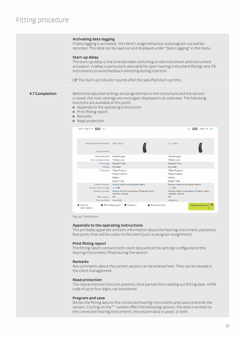
Before the adjusted settings are programmed to the instrument and the session is saved, the main settings are once again displayed in an overview. The following functions are available at this point: Appendix to the operating instructions Print fitting report Remarks Read protection
Fig. 44: Completion
Appendix to the operating instructionsThis printable appendix contains information about the hearing instrument used and a few points that will be useful to the client (such as program assignment).
Print fitting reportThe fitting report contains both client data and all the settings configured on the hearing instruments fitted during the session.
RemarksAny comments about the current session can be entered here. They can be viewed in the client management.
Read protectionThe read protection function prevents third parties from reading out fitting data. A PIN code of up to four digits can be entered.
Program and saveWrites the fitting data to the connected hearing instruments and saves and ends the session. Clicking on the “*” symbol offers the following options: the data is written to the connected hearing instruments, the session data is saved, or both.
4.7 Completion

34
Other program options
Follow-up fitting allows the fitting settings to be adjusted for the following: Hearing instruments belonging to clients who have already had a session New clients who already have hearing instruments
To perform a follow-up fitting, proceed as follows: 1. Select the existing client in the client management or create a new client (for new
clients who already have a hearing instrument).2. Choose whether you would like to continue a session or start a new one.
Fig. 45: Open session
3. Under "Hearing instruments" in the menu, choose "Follow-up fitting"
Fig. 46: Begin fitting
When the "Follow-up fitting" button is selected, the data for the connected hearing instruments is read out and compared with the data saved in the session. If there are discrepancies between the two sets of data, decide whether to use the session data or the data currently on the hearing instrument for the follow-up fitting. Once this selection has been made, the "Fitting" menu item appears.
Fig. 47: Discrepancies between session data and hearing instrument data
If there is no session data available or the session data and the data on the hearing instrument are identical, you will be taken directly to "Fitting" in the menu.
The follow-up fitting process is the same as that already explained from Chapter 4.5, "Fitting" onwards.
During the follow-up fitting, the "Preset" menu item, and thus the First Fit, will be skipped, as these steps have already been carried out in a previous session.
audifit 5 enables the export and import of client data. This means that client records from several installations can be synchronised, or client data can be transferred from audifit 4.
Exporting client informationSelect "Export clients" from the menu bar:
Fig. 48: Exporting client information
5 Other program options
5.1 Follow-up fitting
5.2 Exporting/importing client information
35
Other program options
Once the file name and location have been selected, all client data contained in the client management will be exported as an XML file.
Importing client informationThe import function allows clients to be imported from audifit 4 and audifit 5. To do so, select "Import clients" from the menu bar:
Fig. 49: Importing client information
Once you have selected an XML or AF4 file, all client data it contains will be transferred to the audifit 5 client management.
You can import the following file types: AF4 file format: client data exported from audifit 4 XML file format: client data exported from audifit 5
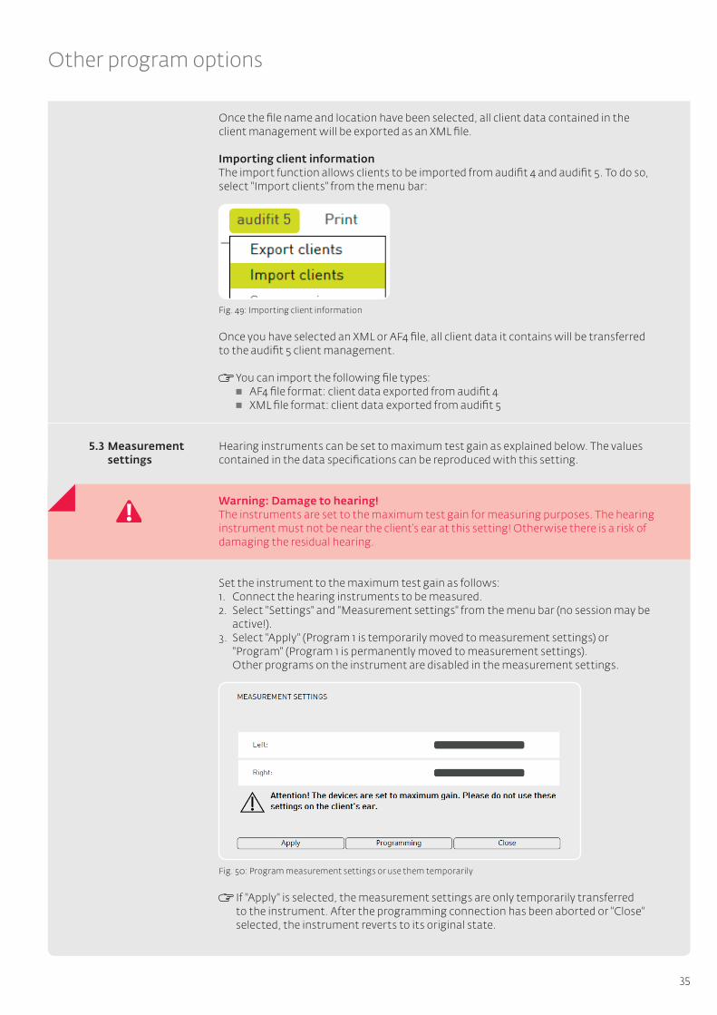
Hearing instruments can be set to maximum test gain as explained below. The values contained in the data specifications can be reproduced with this setting.
Warning: Damage to hearing!The instruments are set to the maximum test gain for measuring purposes. The hearing instrument must not be near the client’s ear at this setting! Otherwise there is a risk of damaging the residual hearing.
Set the instrument to the maximum test gain as follows:1. Connect the hearing instruments to be measured.2. Select "Settings" and "Measurement settings" from the menu bar (no session may be
active!).3. Select "Apply" (Program 1 is temporarily moved to measurement settings) or
"Program" (Program 1 is permanently moved to measurement settings). Other programs on the instrument are disabled in the measurement settings.
Fig. 50: Program measurement settings or use them temporarily
If "Apply" is selected, the measurement settings are only temporarily transferred to the instrument. After the programming connection has been aborted or "Close" selected, the instrument reverts to its original state.
5.3 Measurement settings
36
Troubleshooting
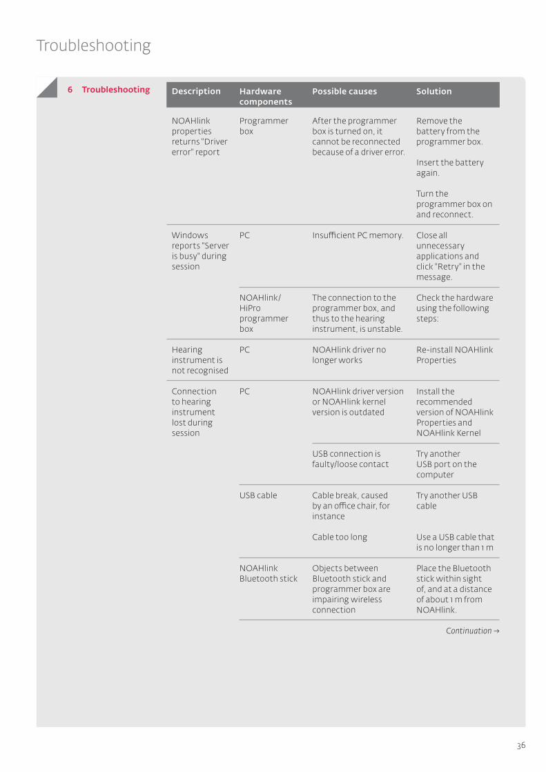
6 Troubleshooting Description
NOAHlink properties returns "Driver error" report
Windows reports "Server is busy" during session
Hearing instrument is not recognised
Connection to hearing instrument lost during session
Programmer box
PC
NOAHlink/HiPro programmer box
PC
PC
USB cable
NOAHlink Bluetooth stick
After the programmer box is turned on, it cannot be reconnected because of a driver error.
Insufficient PC memory.
The connection to the programmer box, and thus to the hearing instrument, is unstable.
NOAHlink driver no longer works
NOAHlink driver version or NOAHlink kernel version is outdated
USB connection is faulty/loose contact
Cable break, caused by an office chair, for instance
Cable too long
Objects between Bluetooth stick and programmer box are impairing wireless connection
Remove the battery from the programmer box.
Insert the battery again.
Turn the programmer box on and reconnect.
Close all unnecessary applications and click "Retry" in the message.
Check the hardware using the following steps:
Re-install NOAHlink Properties
Install the recommended version of NOAHlink Properties and NOAHlink Kernel
Try another USB port on the computer
Try another USB cable
Use a USB cable that is no longer than 1 m
Place the Bluetooth stick within sight of, and at a distance of about 1 m from NOAHlink.
SolutionHardware components
Possible causes
Continuation →

37
Troubleshooting
Description
NOAHlink/HiPro programmer box
Programming cable, programming cable adapter
NOAHlink battery is dead or no longer effective, PC LED lit red
When the programmer box is accessed, the PC LED does not flash.
When the connected hearing instruments are recognised, the LEDs on the programmer box ("left"/"right") do not flash.
Cable selection
Broken cable
Insert a newly recharged battery
Under "Options" in the fitting software, choose the connected programmer box.
Disconnect and reconnect the USB cable between the PC and programmer box. Pair and connect NOAHlink with NOAHlink Properties.
Restart the fitting software.
Check the cable connection between the programmer box and hearing instrument.
Use the Cable Guide to check the selection of the appropriate programming cable and adapter.
Verify that a battery has been inserted into the ITE instrument.
Use the Cable Guide to check the selection of the appropriate programming cable and adapter.
Replace faulty programming cable
SolutionHardware components
Possible causes
Continuation →
38
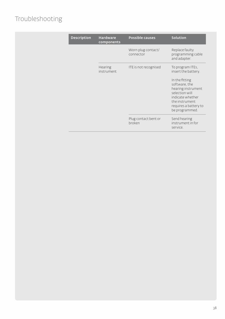
Troubleshooting
Description
Hearing instrument
Worn plug contact/connector
ITE is not recognised
Plug contact bent or broken
Replace faulty programming cable and adapter.
To program ITEs, insert the battery.
In the fitting software, the hearing instrument selection will indicate whether the instrument requires a battery to be programmed.
Send hearing instrument in for service.
SolutionHardware components
Possible causes
39
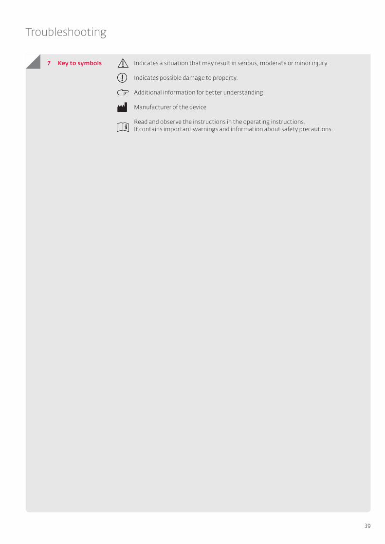
Troubleshooting
7 Key to symbols Indicates a situation that may result in serious, moderate or minor injury.
Indicates possible damage to property.
Additional information for better understanding Manufacturer of the device
Read and observe the instructions in the operating instructions. It contains important warnings and information about safety precautions.

40
Glossary
Adaptive directionalityDuring adaptive directionality, the signals from two microphones are offset against one another, to suppresses any disruptive noise, that could affect the speech comprehension of the person wearing the hearing instrument, as effectively as possible. In this case, the basic assumption is that the useful signal comes from the front, which is why it is not affected. Adaptive directionality is a tried and tested and important technology for improving speech comprehension in noisy environments.
Adaptive feedback cancellation (AFC/AFC²) An essential feature and especially provides an efficient feedback management system for open supplies. Adaptive systems continuously evaluate the feedback path to also be able to react to changing and acoustically challenging situations. Depending on the technology, the gain is reduced or inversely phased signals are used to avoid or remove any feedback. Due to these strategies, significantly higher and stable gains can be implemented during fittings.
Adaptive ambient noise reduction (ANR)Adaptive ambient noise reductions are used to make it easier for the person wearing the hearing instrument to understand speech in noisy situations and to ensure that noisy environments are not as intrusive. In this context, the input signal is continuously analysed over the entire frequency range in relation to the distance of the noise signal and the gain is temporarily reduced in frequency ranges with a poor SNR.
Auto T-CoilAuto T-Coil is a hearing instrument function that is designed to ensure the hearing instrument automatically activates the T-Coil via a magnetic field (e.g. via a telephone receiver with a magnet glued on, if required).
Auto PhoneAuto Phone functions like Auto T-Coil, although a hearing program for the automatic activation can be implemented as required.
Binaural T-CoilIn this mode, the signal received via the T-Coil is transmitted to the hearing system on the other ear so that the signal is audible on both sides. If desired, the slightly reduced microphone signal can also be added.
Crossfader audifon hearing instruments offer a crossfader to minimise potential variations in signal strength when switching between programs: As soon as the hearing program is changed, the audio signal fades out, and the program switch tone (if featured) sounds; the audio signal only cuts in again after you have switched to the new hearing program.
Data loggingThe data logging function records the client’s usage behaviour. The recorded data, such as information about the duration of usage, duration of use per program and Sound Dynamix, can be read out from the connected hearing instrument.
easyclickeasyclick wirelessly synchronises the program or volume settings of two hearing systems.
Expansion (Squelch) Squelch is an expansion circuit which is intended to reduce or eliminate microphone noise by dimming the gain as the input sound pressure decreases.
8 Glossary
41
Glossary
Notch filterThe notch filter is an electronic filter used to filter out frequencies within a narrow frequency range. The notch filter can be used to attenuate unwanted feedback and interfering frequencies by reducing the signal level of the relevant frequency.
Sound DynamixSound Dynamix constantly analyses the signal recorded by the microphones and classifies it as one of the following hearing situations: Quiet Speech in a quiet setting Noise Speech in noise Music Wind noise
According to this classification, the parameter settings of the hearing system are always configured to ensure optimum hearing comfort/optimum speech intelligibility.
Wireless Audio StreamingIf Wireless Audio Streaming is activated in Program 3, the hearing system can receive audio signals from the multistreamer.
Wireless Phone StreamingIf Wireless Phone Streaming is activated in Program 4, phone calls can be received directly in the hearing systems with the multistreamer.
Art
. No.
021
314-
00
2-33
9-17
37
Rev
isio
n da
te 10
/20
16
Solutions for better hearing
www.audifon.com
audifon GmbH & Co. KGWerner-von-Siemens-Straße 299625 KölledaGermany
Head office
Telephone +49-3635-4056-590Fax +49-3635-4056-589
Visit www.audifon.com to find out about our Partner Resources:
Service CentreDownload the latest technical information for service and maintenance, including the latest versions of our audifon software.