Embed Size (px)
Citation preview
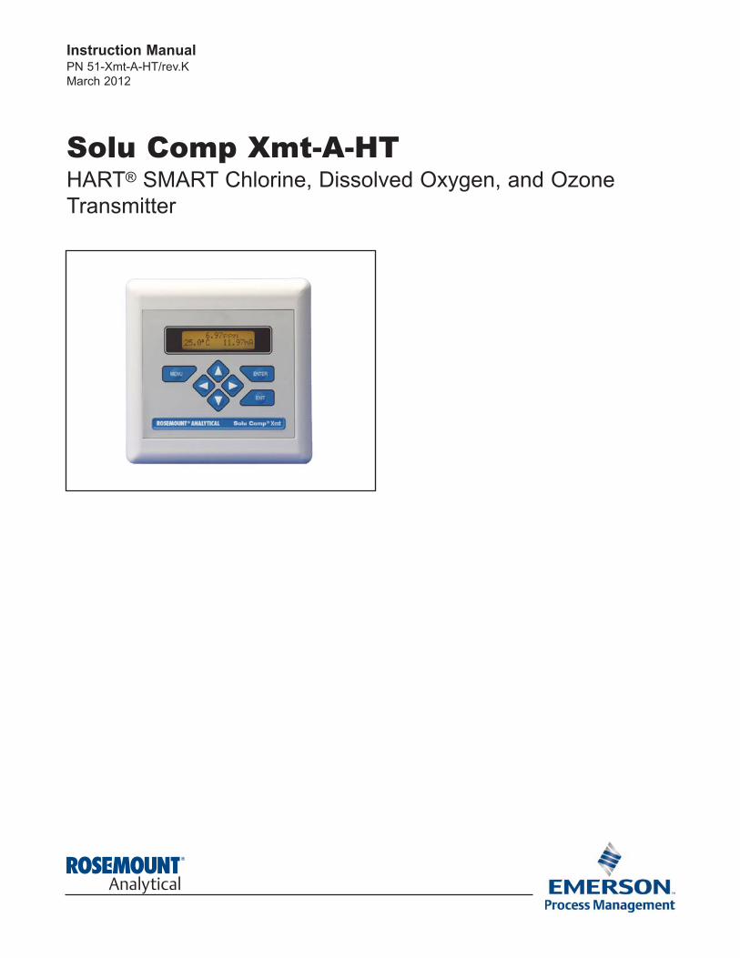
Solu Comp Xmt-A-HTHART® SMART Chlorine, Dissolved Oxygen, and Ozone
Transmitter
Instruction ManualPN 51-Xmt-A-HT/rev.K
March 2012
ESSENTIAL INSTRUCTIONSREAD THIS PAGE BEFORE PROCEEDING!
Rosemount Analytical designs, manufactures, and tests its products to meet many national and international
standards. Because these instruments are sophisticated technical products, you must properly install, use, and
maintain them to ensure they continue to operate within their normal specifications. The following instructions
must be adhered to and integrated into your safety program when installing, using, and maintaining Rosemount
Analytical products. Failure to follow the proper instructions may cause any one of the following situations to
occur: Loss of life; personal injury; property damage; damage to this instrument; and warranty invalidation.
• Read all instructions prior to installing, operating, and servicing the product. If this Instruction Manual is not the
correct manual, telephone 1-800-654-7768 and the requested manual will be provided. Save this Instruction
Manual for future reference.
• If you do not understand any of the instructions, contact your Rosemount representative for clarification.
• Follow all warnings, cautions, and instructions marked on and supplied with the product.
• Inform and educate your personnel in the proper installation, operation, and maintenance of the product.
• Install your equipment as specified in the Installation Instructions of the appropriate Instruction Manual and per
applicable local and national codes. Connect all products to the proper electrical and pressure sources.
• To ensure proper performance, use qualified personnel to install, operate, update, program, and maintain the
product.
• When replacement parts are required, ensure that qualified people use replacement parts specified by
Rosemount. Unauthorized parts and procedures can affect the product’s performance and place the safe
operation of your process at risk. Look alike substitutions may result in fire, electrical hazards, or improper
operation.
• Ensure that all equipment doors are closed and protective covers are in place, except when maintenance is
being performed by qualified persons, to prevent electrical shock and personal injury.
Emerson Process Management
2400 Barranca Parkway
Irvine, CA 92606 USA
Tel: (949) 757-8500
Fax: (949) 474-7250
http://www.rosemountanalytical.com
© Rosemount Analytical Inc. 2012
CAUTION
If a Model 375 Universal Hart® Communicator is used with these
transmitters, the software within the Model 375 may require
modification.
If a software modification is required, please contact your local
Emerson Process Management Service Group or National Response
Center at 1-800-654-7768.
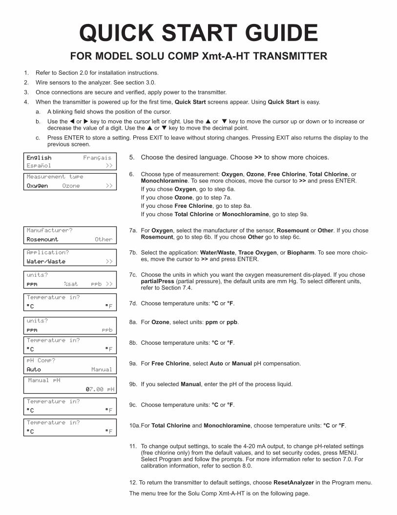
5. Choose the desired language. Choose >> to show more choices.
6. Choose type of measurement: Oxygen, Ozone, Free Chlorine, Total Chlorine, orMonochloramine. To see more choices, move the cursor to >> and press ENTER.
If you chose Oxygen, go to step 6a.
If you chose Ozone, go to step 7a.
If you chose Free Chlorine, go to step 8a.
If you chose Total Chlorine or Monochloramine, go to step 9a.
7a. For Oxygen, select the manufacturer of the sensor, Rosemount or Other. If you choseRosemount, go to step 6b. If you chose Other go to step 6c.
7b. Select the application: Water/Waste, Trace Oxygen, or Biopharm. To see more choic-es, move the cursor to >> and press ENTER.
7c. Choose the units in which you want the oxygen measurement dis-played. If you chosepartialPress (partial pressure), the default units are mm Hg. To select different units,refer to Section 7.4.
7d. Choose temperature units: °C or °F.
8a. For Ozone, select units: ppm or ppb.
8b. Choose temperature units: °C or °F.
9a. For Free Chlorine, select Auto or Manual pH compensation.
9b. If you selected Manual, enter the pH of the process liquid.
9c. Choose temperature units: °C or °F.
10a.For Total Chlorine and Monochloramine, choose temperature units: °C or °F.
11. To change output settings, to scale the 4-20 mA output, to change pH-related settings(free chlorine only) from the default values, and to set security codes, press MENU.Select Program and follow the prompts. For more information refer to section 7.0. Forcalibration information, refer to section 8.0.
12. To return the transmitter to default settings, choose ResetAnalyzer in the Program menu.
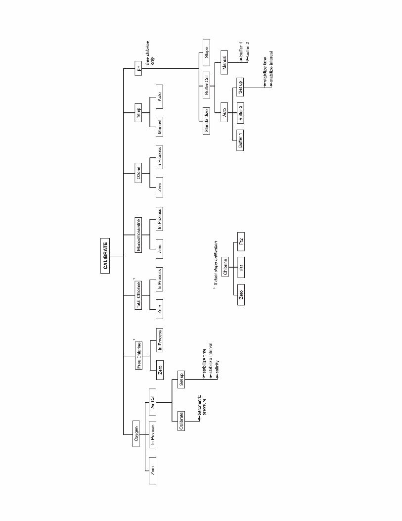
The menu tree for the Solu Comp Xmt-A-HT is on the following page.
Measurement type
Oxygen Ozone >>
units?
ppm %sat ppb >>
units?
ppm ppb
Application?
Water/Waste >>
Manufacturer?
Rosemount Other
Temperature in?
°C °F
Temperature in?
°C °F
pH Comp?
Auto Manual
Manual pH
07.00 pH
Temperature in?
°C °F
Temperature in?
°C °F
1. Refer to Section 2.0 for installation instructions.
2. Wire sensors to the analyzer. See section 3.0.
3. Once connections are secure and verified, apply power to the transmitter.
4. When the transmitter is powered up for the first time, Quick Start screens appear. Using Quick Start is easy.
a. A blinking field shows the position of the cursor.
b. Use the t or u key to move the cursor left or right. Use the p or q key to move the cursor up or down or to increase ordecrease the value of a digit. Use the p or q key to move the decimal point.
c. Press ENTER to store a setting. Press EXIT to leave without storing changes. Pressing EXIT also returns the display to theprevious screen.
QUICK START GUIDEFOR MODEL SOLU COMP Xmt-A-HT TRANSMITTER
English Français
Español >>

QU
ICK
STA
RT
GU
IDE
ME
NU
TR
EE
FO
R M
OD
EL
SO
LU
CO
MP
Xm
t-A
-HT
TR
AN
SM
ITT
ER L
an
gu
ag
e

i
MODEL XMT-A-HT TABLE OF CONTENTS
MODEL XMT-A-HT MICROPROCESSOR TRANSMITTER
TABLE OF CONTENTS
Section Title Page
1.0 DESCRIPTION AND SPECIFICATIONS ................................................................ 1
1.1 Features and Applications........................................................................................ 1
1.2 Specifications - General ........................................................................................... 2
1.3 Specifications - Oxygen ........................................................................................... 4
1.4 Specifications - Free Chlorine .................................................................................. 4
1.5 Specifications - Total Chlorine.................................................................................. 4
1.6 Specifications - Monochloramine ............................................................................. 4
1.7 Specifications - Ozone ............................................................................................ 4
1.8 Transmitter Display During Calibration and Programming ...................................... 5
1.9 HART Communication ............................................................................................. 5
1.10 Ordering Information ............................................................................................... 6
1.11 Accessories ............................................................................................................. 6
2.0 INSTALLATION ....................................................................................................... 7
2.1 Unpacking and Inspection........................................................................................ 7
2.2 Installation................................................................................................................ 7
2.3 Power Supply/Current Loop..................................................................................... 11
3.0 SENSOR WIRING ................................................................................................... 14
3.1 Wiring Model 499A Oxygen, Chlorine, Monochloramine, and Ozone Sensors........ 14
3.2 Wiring Model 499ACL-01 (Free Chlorine) Sensors and pH Sensors....................... 15
3.3 Wiring Model Hx438, Gx448, and Bx438 Sensors................................................... 18
4.0 INTRINSICALLY SAFE AND EXPLOSION PROOF INSTALLATIONS.................. 19
5.0 DISPLAY AND OPERATION ................................................................................... 28
5.1 Display ..................................................................................................................... 28
5.2 Keypad..................................................................................................................... 28
5.3 Programming and Calibrating the Model Xmt — Tutorial......................................... 29
5.4 Security .................................................................................................................... 30
5.5 Using Hold ............................................................................................................... 30
6.0 OPERATION WITH MODEL 375............................................................................. 31
6.1 Note on Model 375 HART Communicator................................................................ 31
6.2 Connecting the HART Communicator...................................................................... 31
6.3 Operation ................................................................................................................. 32
7.0 PROGRAMMING..................................................................................................... 37
7.1 General .................................................................................................................... 37
7.2 Changing Start-up Settings ...................................................................................... 37
7.3 Configuring and Ranging the Output ....................................................................... 39
7.4 Choosing and Configuring the Analytical Measurement .......................................... 42
7.5 Making Temperature Settings .................................................................................. 46
7.6 Setting a Security Code ........................................................................................... 47
7.7 Making HART-Related Settings ............................................................................... 48
7.8 Noise Reduction....................................................................................................... 48
7.9 Resetting Factory Calibration and Factory Default Settings .................................... 48
7.10 Selecting a Default Screen and Screen Contrast .................................................... 49

MODEL XMT-A-HT TABLE OF CONTENTS
TABLE OF CONTENTS CONT’D
Section Title Page
8.0 CALIBRATION — TEMPERATURE........................................................................ 50
8.1 Introduction .............................................................................................................. 50
8.2 Procedure — Calibrating Temperature .................................................................... 51
9.0 CALIBRATION — DISSOLVED OXYGEN.............................................................. 52
9.1 Introduction .............................................................................................................. 52
9.2 Procedure — Zeroing the Sensor ............................................................................ 53
9.3 Procedure — Calibrating the Sensor in Air .............................................................. 54
9.4 Procedure — Calibrating the Sensor Against a Standard Instrument ...................... 56
10.0 CALIBRATION — FREE CHLORINE ..................................................................... 57
10.1 Introduction .............................................................................................................. 57
10.2 Procedure — Zeroing the Sensor ............................................................................ 58
10.3 Procedure — Full Scale Calibration......................................................................... 59
10.4 Dual Slope Calibration ............................................................................................. 60
11.0 CALIBRATION — TOTAL CHLORINE ................................................................... 62
11.1 Introduction .............................................................................................................. 62
11.2 Procedure — Zeroing the Sensor ............................................................................ 63
11.3 Procedure — Full Scale Calibration......................................................................... 64
11.4 Dual Slope Calibration ............................................................................................. 65
12.0 CALIBRATION — MONOCHLORAMINE ............................................................... 67
12.1 Introduction .............................................................................................................. 67
12.2 Procedure — Zeroing the Sensor ............................................................................ 68
12.3 Procedure — Full Scale Calibration......................................................................... 69
13.0 CALIBRATION — OZONE ...................................................................................... 70
13.1 Introduction .............................................................................................................. 70
13.2 Procedure — Zeroing the Sensor ............................................................................ 71
13.3 Procedure — Full Scale Calibration......................................................................... 72
14.0 CALIBRATION — pH .............................................................................................. 73
14.1 Introduction .............................................................................................................. 73
14.2 Procedure — Auto Calibration ................................................................................. 74
14.3 Procedure — Manual Calibration............................................................................. 76
14.4 Procedure — Standardization .................................................................................. 77
14.5 Procedure — Entering a Known Slope Value .......................................................... 78
ii
iii
MODEL XMT-A-HT TABLE OF CONTENTS
TABLE OF CONTENTS CONT’D
Section Title Page
15.0 TROUBLESHOOTING ........................................................................................... 79
15.1 Overview .................................................................................................................. 79
15.2 Troubleshooting When a Fault or Warning Message is Showing ............................ 80
15.3 Troubleshooting When No Fault Message is Showing — Temperature................... 82
15.4 Troubleshooting When No Fault Message is Showing — Oxygen .......................... 83
15.5 Troubleshooting When No Fault Message is Showing — Free Chlorine................. 86
15.6 Troubleshooting When No Fault Message is Showing — Total Chlorine................. 88
15.7 Troubleshooting When No Fault Message is Showing — Monochloramine ............ 89
15.8 Troubleshooting When No Fault Message is Showing — Ozone ............................ 92
15.9 Troubleshooting When No Fault Message is Showing — pH .................................. 94
15.10 Troubleshooting Not Related to Measurement Problems ........................................ 97
15.11 Simulating Input Currents — Dissolved Oxygen...................................................... 97
15.12 Simulating Input Currents — Chlorine and Ozone................................................... 98
15.13 Simulating Inputs — pH ........................................................................................... 99
15.14 Simulating Temperature ........................................................................................... 100
15.15 Measuring Reference Voltage.................................................................................. 101
16.0 MAINTENANCE ...................................................................................................... 102
17.0 RETURN OF MATERIAL......................................................................................... 103
Appendix Title Page
A BAROMETRIC PRESSURE AS A FUNCTION OF ALTITUDE............................... 104
LIST OF TABLES
Number Title Page
7-1 Default Settings ....................................................................................................... 38
iv
MODEL XMT-A-HT TABLE OF CONTENTS
LIST OF FIGURES
Number Title Page
1-1 HART Communication.............................................................................................. 5
2-1 Removing the Knockouts ......................................................................................... 7
2-2 Panel Mount Installation........................................................................................... 8
2-3 Pipe Mount Installation............................................................................................. 9
2-4 Surface Mount Installation........................................................................................ 10
2-5 Load/Power Supply Requirements........................................................................... 11
2-6 Power Supply/Current Loop Wiring.......................................................................... 12
2-7 Power & Sensor Wiring Terminals and Wiring Label for Xmt-A-HT Panel Mount ... 12
2-8 Power & Sensor Wiring Terminals and Wiring Label for Xmt-A-HT Pipe/Surface Mount 13
3-1 Xmt-A-HT panel mount; 499A sensors with standard cable .................................... 14
3-2 Xmt-A-HT panel mount; 499A sensors with optimum EMI/RFI cable or Variopol cable 14
3-3 Xmt-A-HT wall/pipe mount; 499A sensors with standard cable ............................... 14
3-4 Xmt-A-HT wall/pipe mount; 499A sensors with optimum EMI/RFI cable or ...........
Variopol cable .................................................................................................... 14
3-5 Xmt-A-HT panel mount; free chlorine sensor with standard cable and 399-09-62 .
pH sensor .................................................................................................... 15
3-6 Xmt-A-HT panel mount; free chlorine sensor with standard cable and 399-VP-09
pH sensor .................................................................................................... 15
3-7 Xmt-A-HT panel mount; free chlorine sensor with standard cable and 399-14 pH
sensor .................................................................................................... 16
3-8 Xmt-A-HT panel mount; free chlorine sensor with optimum EMI/RFI cable or ......
Variopol cable and 399-09-62 pH sensor................................................................. 16
3-9 Xmt-A-HT panel mount; free chlorine sensor with optimum EMI/RFI cable or ......
Variopol cable and 399-VP-09 pH sensor................................................................ 16
3-10 Xmt-A-HT panel mount; free chlorine sensor with optimum EMI/RFI cable or ......
Variopol cable and 399-14 pH sensor...................................................................... 17
3-11 Xmt-A-HT wall/pipe mount; free chlorine sensor with standard cable and 399-09-62
pH sensor .................................................................................................... 17
3-12 Xmt-A-HT wall/pipe mount; free chlorine sensor with standard cable and .............
399-VP-09pH sensor................................................................................................ 17
3-13 Xmt-A-HT wall/pipe mount; free chlorine sensor with standard cable and 399-14 .
pH sensor .................................................................................................... 17
3-14 Xmt-A-HT wall/pipe mount; free chlorine sensor with optimum EMI/RFI cable or
Variopol cable and 399-09-62 pH sensor................................................................. 17
3-15 Xmt-A-HT wall/pipe mount; free chlorine sensor with optimum EMI/RFI cable or
Variopol cable and 399-VP-09 pH sensor................................................................ 18
3-16 Xmt-A-HT wall/pipe mount; free chlorine sensor with optimum EMI/RFI cable or
Variopol cable and 399-14 pH sensor...................................................................... 18
3-17 Xmt-A-HT panel mount with Hx438 or Gx448 sensor.............................................. 18
3-18 Xmt-A-HT wall/pipe mount with Hx438 or Gx448 sensor ........................................ 18
3-19 Wiring Model Bx438 to Xmt-A-HT-10....................................................................... 18
3-20 Wiring Model Bx438 to Xmt-A-HT-11 ....................................................................... 18
4-1 FM Intrinsically Safe Installation Label..................................................................... 19
4-2 FM Intrinsically Safe Installation Wiring ................................................................... 20
4-3 CSA Intrinsically Safe Installation Label................................................................... 22
4-4 CSA Intrinsically Safe Installation Wiring ................................................................. 23

About This Document
This manual contains instructions for installation and operation of the Model Solu Comp Xmt-A-HT Dissolved
Oxygen, Chlorine, and Ozone Transmitter.
The following list provides notes concerning all revisions of this document.
Rev. Level Date Notes
A 9/03 This is the initial release of the product manual.
B 12/03 Added note to troubleshooting, p. 70.
C 9/04 Added agency wiring drawings.
D 11/04 Updated mounting drawings.
E 4/05 Revised panel mount drawing.
F 9/05 Added Foundation fieldbus agency approvals and FISCO version.
G 2/06 Revised section 1.0, p. 1, and substituted standard text on 1.2, p.2.
H 6/06 Revised Quick Start choices adding language as #5. Added Language
box to Quick start guide on page D. Deleted 230A in accessories chart on page 5.
I 10/08 Addition of Hazardous Location Approvals.
J 05/10 Include EC Certificates on page 107
K 03/12 Update addresses - mail and web and DNV certificate logo
MODEL XMT-A-HT TABLE OF CONTENTS
LIST OF FIGURES (continued)
Number Title Page
4-5 Baseefa/ATEX Intrinsically Safe Installation Label................................................... 25
4-6 Baseefa/ATEX Intrinsically Safe Installation Wiring ................................................. 26
5-1 Displays During Normal Operation........................................................................... 28
5-2 Solu Comp II Keypad ............................................................................................... 28
6-1 Connecting the HART Communicator...................................................................... 31
6-2 Xmt-A-HT HART/Model 275 Menu Tree .................................................................. 33
9-1 Sensor Current as a Function of Dissolved Oxygen Concentration ........................ 52
10-1 Sensor Current as a Function of Free Chlorine Concentration ............................... 57
10-2 Dual Slope Calibration ............................................................................................. 60
11-1 Determination of Total Chlorine................................................................................ 62
11-2 Sensor Current as a Function of Total Chlorine Concentration ............................... 62
11-3 Dual Slope Calibration ............................................................................................. 65
12-1 Sensor Current as a Function of Monochloramine Concentration........................... 67
13-1 Sensor Current as a Function of Ozone Concentration........................................... 70
14-1 Calibration Slope and Offset .................................................................................... 72
15-1 Simulate dissolved oxygen....................................................................................... 97
15-2 Simulate chlorine and ozone.................................................................................... 98
15-3 Simulate pH.............................................................................................................. 99
15-4 Three-wire RTD Configuration ................................................................................. 100
15-5 Simulating RTD Inputs ............................................................................................. 100
15-6 Checking for a Poisoned Reference Electrode........................................................ 101
16-1 Exploded View of Model Xmt-A-HT Transmitter ...................................................... 102
v
1
MODEL XMT-A-HT SECTION 1.0
DESCRIPTION AND SPECIFICATIONS
SECTION 1.0DESCRIPTION AND SPECIFICATIONS
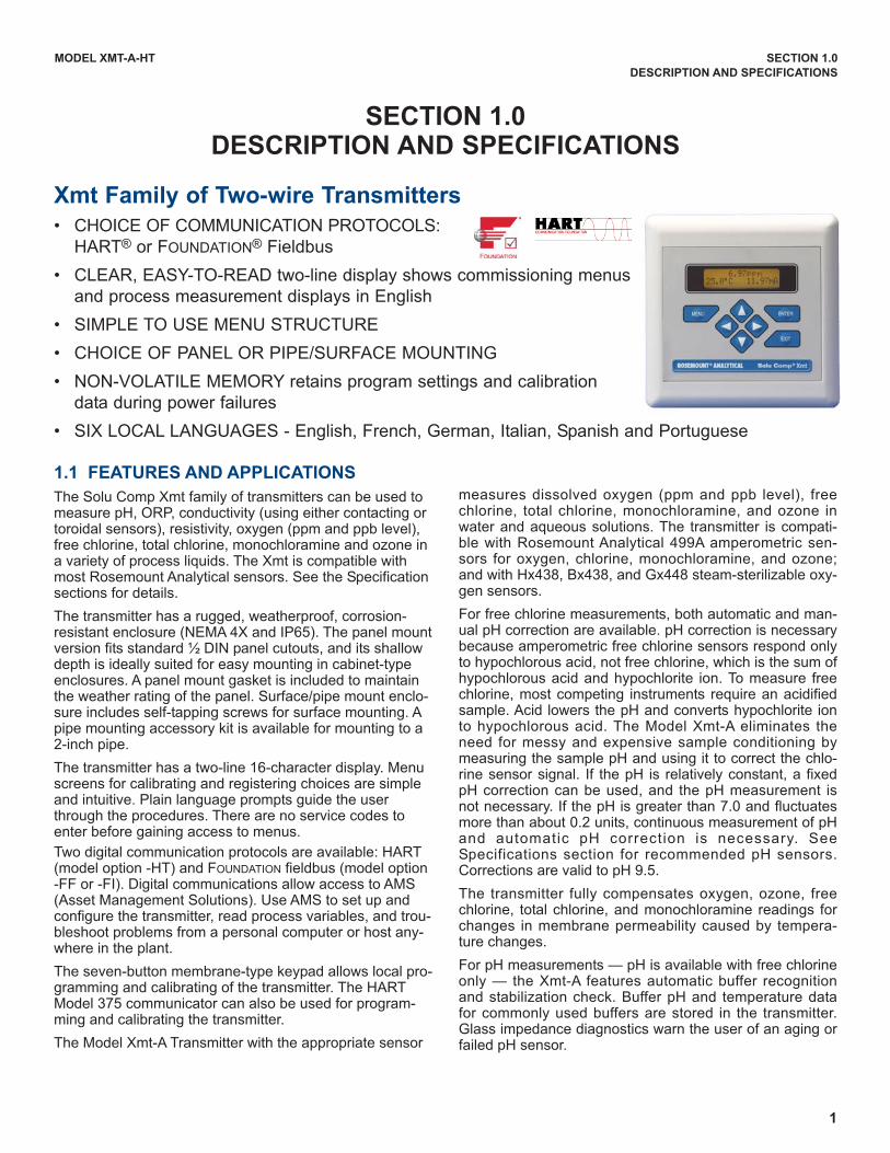
Xmt Family of Two-wire Transmitters
• CHOICE OF COMMUNICATION PROTOCOLS:
HART® or FOUNDATION® Fieldbus
• CLEAR, EASY-TO-READ two-line display shows commissioning menus
and process measurement displays in English
• SIMPLE TO USE MENU STRUCTURE
• CHOICE OF PANEL OR PIPE/SURFACE MOUNTING
• NON-VOLATILE MEMORY retains program settings and calibration
data during power failures
• SIX LOCAL LANGUAGES - English, French, German, Italian, Spanish and Portuguese
1.1 FEATURES AND APPLICATIONS
The Solu Comp Xmt family of transmitters can be used tomeasure pH, ORP, conductivity (using either contacting ortoroidal sensors), resistivity, oxygen (ppm and ppb level),free chlorine, total chlorine, monochloramine and ozone ina variety of process liquids. The Xmt is compatible withmost Rosemount Analytical sensors. See the Specificationsections for details.
The transmitter has a rugged, weatherproof, corrosion-resistant enclosure (NEMA 4X and IP65). The panel mountversion fits standard ½ DIN panel cutouts, and its shallowdepth is ideally suited for easy mounting in cabinet-typeenclosures. A panel mount gasket is included to maintainthe weather rating of the panel. Surface/pipe mount enclo-sure includes self-tapping screws for surface mounting. Apipe mounting accessory kit is available for mounting to a2-inch pipe.
The transmitter has a two-line 16-character display. Menuscreens for calibrating and registering choices are simpleand intuitive. Plain language prompts guide the userthrough the procedures. There are no service codes toenter before gaining access to menus.
Two digital communication protocols are available: HART(model option -HT) and FOUNDATION fieldbus (model option-FF or -FI). Digital communications allow access to AMS(Asset Management Solutions). Use AMS to set up andconfigure the transmitter, read process variables, and trou-bleshoot problems from a personal computer or host any-where in the plant.
The seven-button membrane-type keypad allows local pro-gramming and calibrating of the transmitter. The HARTModel 375 communicator can also be used for program-ming and calibrating the transmitter.
The Model Xmt-A Transmitter with the appropriate sensor
measures dissolved oxygen (ppm and ppb level), freechlorine, total chlorine, monochloramine, and ozone inwater and aqueous solutions. The transmitter is compati-ble with Rosemount Analytical 499A amperometric sen-sors for oxygen, chlorine, monochloramine, and ozone;and with Hx438, Bx438, and Gx448 steam-sterilizable oxy-gen sensors.
For free chlorine measurements, both automatic and man-ual pH correction are available. pH correction is necessarybecause amperometric free chlorine sensors respond onlyto hypochlorous acid, not free chlorine, which is the sum ofhypochlorous acid and hypochlorite ion. To measure freechlorine, most competing instruments require an acidifiedsample. Acid lowers the pH and converts hypochlorite ionto hypochlorous acid. The Model Xmt-A eliminates theneed for messy and expensive sample conditioning bymeasuring the sample pH and using it to correct the chlo-rine sensor signal. If the pH is relatively constant, a fixedpH correction can be used, and the pH measurement isnot necessary. If the pH is greater than 7.0 and fluctuatesmore than about 0.2 units, continuous measurement of pHand automatic pH correction is necessary. SeeSpecifications section for recommended pH sensors.Corrections are valid to pH 9.5.
The transmitter fully compensates oxygen, ozone, freechlorine, total chlorine, and monochloramine readings forchanges in membrane permeability caused by tempera-ture changes.
For pH measurements — pH is available with free chlorineonly — the Xmt-A features automatic buffer recognitionand stabilization check. Buffer pH and temperature datafor commonly used buffers are stored in the transmitter.Glass impedance diagnostics warn the user of an aging orfailed pH sensor.

2
MODEL XMT-A-HT SECTION 1.0
DESCRIPTION AND SPECIFICATIONS
1.2 SPECIFICATIONS - GENERAL
Case: ABS (panel mount), polycarbonate (pipe/wall mount);
NEMA 4X/CSA 4 (IP65)
Dimensions
Panel (code -10): 6.10 x 6.10 x 3.72 in. (155 x 155 x
94.5 mm)
Surface/Pipe (code -11): 6.23 x 6.23 x 3.23 in. (158
x 158 x 82 mm); see page 5 for dimensions of pipe
mounting bracket.
Conduit openings: Accepts PG13.5 or 1/2 in. conduit fit-
tings
Ambient Temperature: 32 to 122°F (0 to 50°C). Somedegradation of display above 50°C.
Storage Temperature: -4 to 158°F (-20 to 70°C)
Relative Humidity: 10 to 90% (non-condensing)
Weight/Shipping Weight: 10 lb/10 lb (4.5/5.0 kg)
Display: Two line, 16-character display. Character height:
4.8 mm; first line shows process variable (oxygen,
ozone, free chlorine, total chlorine, or monochlo-
ramine), second line shows process temperature and
output current. For pH/chlorine combination, pH may
also be displayed. Fault and warning messages,
when triggered, alternate with temperature and output
readings.
During calibration and programming, messages,
prompts, and editable values appear in the two-line
display.
Temperature resolution: 0.1°C (≤99.9°C);
1°C (≥100°C)
Input ranges: 0-330 nA, 0.3-4µA, 3.7-30 µA, 27-100 µA
Repeatability (input): ±0.1% of range
Linearity (input): ±0.3% of range
Temperature range: 0-100°C (0-150°C for steam steriliz-
able sensors)
Temperature accuracy using RTD: ±0.5°C between 0
and 50°C, ±1°C above 50°C
Temperature accuracy using 22k NTC: ±0.5°C between
0 and 50°C, ±2°C above 50°C
HART Communications: PV, SV, TV, and 4V assignable
to measurement (oxygen, ozone, or chlorine), temper-
ature, pH, and sensor current.
RFI/EMI: EN-61326
Power & Load Requirements: Supply voltage at the
transmitter terminals should be at least 12 Vdc.
Power supply voltage should cover the voltage drop
on the cable plus the external load resistor required
for HART communications (250 Ω minimum).
Minimum power supply voltage is 12 Vdc. Maximum
power supply voltage is 42.4 Vdc (30 Vdc for intrinsi-
cally safe operation). The graph shows the supply
voltage required to maintain 12 Vdc (upper line) and
30 Vdc (lower line) at the transmitter terminals when
the current is 22 mA.
Analog Output: Two-wire, 4-20 mA output with superim-
posed HART digital signal. Fully scalable over the
operating range of the sensor.
Output accuracy: ±0.05 mA
3
MODEL XMT-A-HT SECTION 1.0
DESCRIPTION AND SPECIFICATIONS
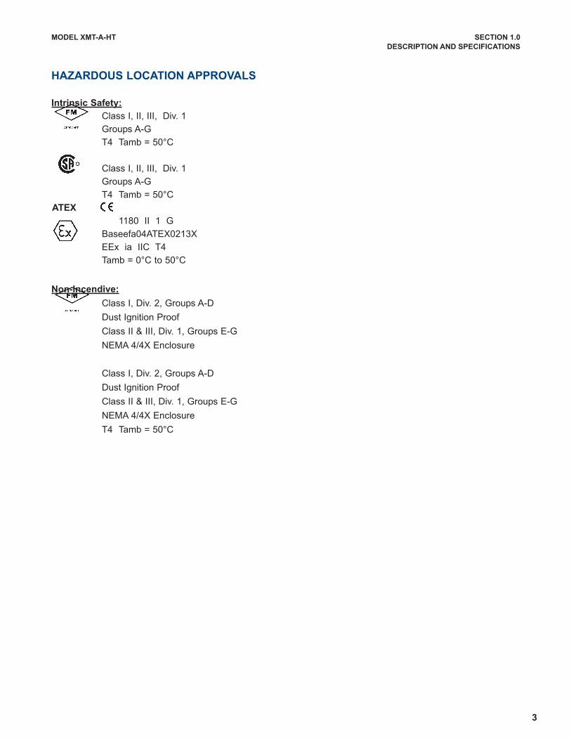
HAZARDOUS LOCATION APPROVALS
Intrinsic Safety:
Class I, II, III, Div. 1
Groups A-G
T4 Tamb = 50°C
Class I, II, III, Div. 1
Groups A-G
T4 Tamb = 50°C
1180 II 1 G
Baseefa04ATEX0213X
EEx ia IIC T4
Tamb = 0°C to 50°C
Non-Incendive:
Class I, Div. 2, Groups A-D
Dust Ignition Proof
Class II & III, Div. 1, Groups E-G
NEMA 4/4X Enclosure
Class I, Div. 2, Groups A-D
Dust Ignition Proof
Class II & III, Div. 1, Groups E-G
NEMA 4/4X Enclosure
T4 Tamb = 50°C
ATEX
4
MODEL XMT-A-HT SECTION 1.0
DESCRIPTION AND SPECIFICATIONS
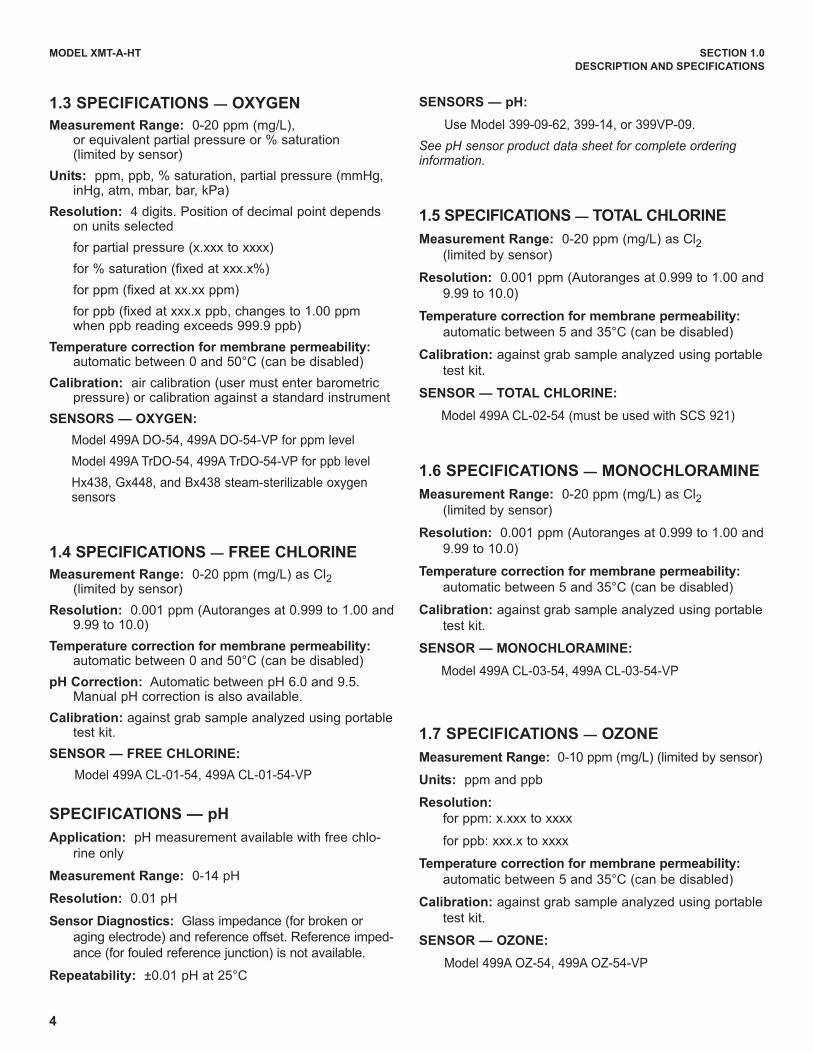
1.3 SPECIFICATIONS — OXYGEN
Measurement Range: 0-20 ppm (mg/L), or equivalent partial pressure or % saturation (limited by sensor)
Units: ppm, ppb, % saturation, partial pressure (mmHg,inHg, atm, mbar, bar, kPa)
Resolution: 4 digits. Position of decimal point dependson units selected
for partial pressure (x.xxx to xxxx)
for % saturation (fixed at xxx.x%)
for ppm (fixed at xx.xx ppm)
for ppb (fixed at xxx.x ppb, changes to 1.00 ppmwhen ppb reading exceeds 999.9 ppb)
Temperature correction for membrane permeability:automatic between 0 and 50°C (can be disabled)
Calibration: air calibration (user must enter barometricpressure) or calibration against a standard instrument
SENSORS — OXYGEN:
Model 499A DO-54, 499A DO-54-VP for ppm level
Model 499A TrDO-54, 499A TrDO-54-VP for ppb level
Hx438, Gx448, and Bx438 steam-sterilizable oxygen sensors
1.4 SPECIFICATIONS — FREE CHLORINE
Measurement Range: 0-20 ppm (mg/L) as Cl2(limited by sensor)
Resolution: 0.001 ppm (Autoranges at 0.999 to 1.00 and9.99 to 10.0)
Temperature correction for membrane permeability:automatic between 0 and 50°C (can be disabled)
pH Correction: Automatic between pH 6.0 and 9.5.Manual pH correction is also available.
Calibration: against grab sample analyzed using portabletest kit.
SENSOR — FREE CHLORINE:
Model 499A CL-01-54, 499A CL-01-54-VP
SPECIFICATIONS — pH
Application: pH measurement available with free chlo-
rine only
Measurement Range: 0-14 pH
Resolution: 0.01 pH
Sensor Diagnostics: Glass impedance (for broken or
aging electrode) and reference offset. Reference imped-
ance (for fouled reference junction) is not available.
Repeatability: ±0.01 pH at 25°C
SENSORS — pH:
Use Model 399-09-62, 399-14, or 399VP-09.
See pH sensor product data sheet for complete orderinginformation.
1.5 SPECIFICATIONS — TOTAL CHLORINE
Measurement Range: 0-20 ppm (mg/L) as Cl2(limited by sensor)
Resolution: 0.001 ppm (Autoranges at 0.999 to 1.00 and
9.99 to 10.0)
Temperature correction for membrane permeability:
automatic between 5 and 35°C (can be disabled)
Calibration: against grab sample analyzed using portable
test kit.
SENSOR — TOTAL CHLORINE:
Model 499A CL-02-54 (must be used with SCS 921)
1.6 SPECIFICATIONS — MONOCHLORAMINE
Measurement Range: 0-20 ppm (mg/L) as Cl2(limited by sensor)
Resolution: 0.001 ppm (Autoranges at 0.999 to 1.00 and
9.99 to 10.0)
Temperature correction for membrane permeability:
automatic between 5 and 35°C (can be disabled)
Calibration: against grab sample analyzed using portable
test kit.
SENSOR — MONOCHLORAMINE:
Model 499A CL-03-54, 499A CL-03-54-VP
1.7 SPECIFICATIONS — OZONE
Measurement Range: 0-10 ppm (mg/L) (limited by sensor)
Units: ppm and ppb
Resolution:
for ppm: x.xxx to xxxx
for ppb: xxx.x to xxxx
Temperature correction for membrane permeability:
automatic between 5 and 35°C (can be disabled)
Calibration: against grab sample analyzed using portable
test kit.
SENSOR — OZONE:
Model 499A OZ-54, 499A OZ-54-VP

5
MODEL XMT-A-HT SECTION 1.0
DESCRIPTION AND SPECIFICATIONS
1.8 TRANSMITTER DISPLAY DURING CALIBRATION AND PROGRAMMING
The display can be readily configured to meet user requirements.
Basic display for all measurements:
For the measurement of oxygen, a variety of units are available: ppm, ppb (for 499ATrDO sensor only), % saturation,
and partial pressure (in units of mm Hg, in Hg, bar, mbar, atm, or kPa).
For chlorine measurements with continuous pH correction, the basic display also shows the pH.
A display showing the raw sensor current can also be selected.
1.9 HART COMMUNICATION (Figure 1-1)
The Model 375 HART Communicator is a hand-held device that provides a common link to all HART SMART instru-
ments and allows access to AMS (Asset Management Solutions). Use the HART communicator to set up and control the
Xmt-A-HT and to read measured variables. Press ON to display the on-line menu. All setup menus are available through
this menu.
FIGURE 1-1. HART Communication
1.234ppm
25.0°C 12.34mA
1.234ppm
7.89pH 25.0°C
1.234ppm
25.0°C 500nA
6
MODEL XMT-A-HT SECTION 1.0
DESCRIPTION AND SPECIFICATIONS
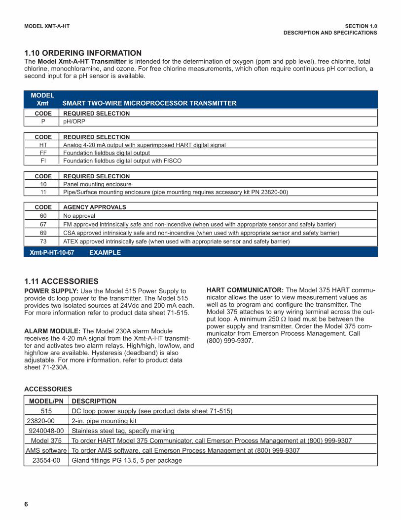
1.10 ORDERING INFORMATIONThe Model Xmt-A-HT Transmitter is intended for the determination of oxygen (ppm and ppb level), free chlorine, totalchlorine, monochloramine, and ozone. For free chlorine measurements, which often require continuous pH correction, asecond input for a pH sensor is available.
ACCESSORIES
MODEL/PN DESCRIPTION
515 DC loop power supply (see product data sheet 71-515)
23820-00 2-in. pipe mounting kit
9240048-00 Stainless steel tag, specify marking
Model 375 To order HART Model 375 Communicator, call Emerson Process Management at (800) 999-9307
AMS software To order AMS software, call Emerson Process Management at (800) 999-9307
23554-00 Gland fittings PG 13.5, 5 per package
1.11 ACCESSORIESPOWER SUPPLY: Use the Model 515 Power Supply toprovide dc loop power to the transmitter. The Model 515provides two isolated sources at 24Vdc and 200 mA each.For more information refer to product data sheet 71-515.
ALARM MODULE: The Model 230A alarm Modulereceives the 4-20 mA signal from the Xmt-A-HT transmit-ter and activates two alarm relays. High/high, low/low, andhigh/low are available. Hysteresis (deadband) is alsoadjustable. For more information, refer to product datasheet 71-230A.
HART COMMUNICATOR: The Model 375 HART commu-nicator allows the user to view measurement values aswell as to program and configure the transmitter. TheModel 375 attaches to any wiring terminal across the out-put loop. A minimum 250 Ω load must be between thepower supply and transmitter. Order the Model 375 com-municator from Emerson Process Management. Call(800) 999-9307.
CODE REQUIRED SELECTION
HT Analog 4-20 mA output with superimposed HART digital signal
FF Foundation fieldbus digital output
FI Foundation fieldbus digital output with FISCO
CODE REQUIRED SELECTION
10 Panel mounting enclosure
11 Pipe/Surface mounting enclosure (pipe mounting requires accessory kit PN 23820-00)
CODE AGENCY APPROVALS
60 No approval
67 FM approved intrinsically safe and non-incendive (when used with appropriate sensor and safety barrier)
69 CSA approved intrinsically safe and non-incendive (when used with appropriate sensor and safety barrier)
73 ATEX approved intrinsically safe (when used with appropriate sensor and safety barrier)
CODE REQUIRED SELECTION
P pH/ORP
MODEL
Xmt SMART TWO-WIRE MICROPROCESSOR TRANSMITTER
Xmt-P-HT-10-67 EXAMPLE

7
MODEL XMT-A-HT SECTION 2.0
INSTALLATION
SECTION 2.0INSTALLATION
Type of Mounting Section
Panel 2.2.2
Pipe 2.2.3
Surface 2.2.4
2.1 UNPACKING AND INSPECTION
Inspect the shipping container. If it is damaged, contact the shipper immediately for instructions. Save the box. Ifthere is no apparent damage, unpack the container. Be sure all items shown on the packing list are present. Ifitems are missing, notify Emerson Process Management immediately.
2.2 INSTALLATION
2.2.1 General Information
1. Although the transmitter is suitable for outdoor use, do not install it in direct sunlight or in areas of extremetemperatures.
2. Install the transmitter in an area where vibrations and electromagnetic and radio frequency interference areminimized or absent.
3. Keep the transmitter and sensor wiring at least one foot from high voltage conductors. Be sure there is easyaccess to the transmitter.
4. The transmitter is suitable for panel, pipe, or surface mounting. Refer to the table below.
5. The transmitter case has two 1/2-inch (PG13.5) conduit openings and four 1/2-inch knockouts. One conduitopening is for the power/output cable; the other opening is for the sensor cable. The center knockout in thebottom of the enclosure should be removed only if a second sensor is required, i.e., if free chlorine with con-tinuous pH correction is being measured. (Note: Earlier versions of the Xmt-A-HT pipe/surface mount trans-mitters may have three openings in the bottom of the enclosure. The transmitter is shipped with a NEMA 4Xplug installed in the center opening.)
Figure 2-1 shows how to remove a knockout. The knockout groovesare on the outside of the case. Place the screwdriver blade on theinside of the case and align it approximately along the groove. Rapthe screwdriver sharply with a hammer until the groove cracks.Move the screwdriver to an uncracked portion of the groove andcontinue the process until the knockout falls out. Use a small knifeto remove the flash from the inside of the hole.
6. Use weathertight cable glands to keep moisture out to the transmit-ter. If conduit is used, plug and seal the connections at the trans-mitter housing to prevent moisture from getting inside the instru-ment.
7. To reduce the likelihood of stress on wiring connections, do notremove the hinged front panel (-11 models) from the base duringwiring installation. Allow sufficient wire length to avoid stress on con-ductors.
FIGURE 2-1. Removing the Knockouts

8
MODEL XMT-A-HT SECTION 2.0
INSTALLATION
FIGURE 2-2. Panel Mount Installation
Access to the wiring terminals is through the rear cover. Four screws hold the cover in place.
2.2.2 Panel Mounting.
MILLIMETER
INCH
9
MODEL XMT-A-HT SECTION 2.0
INSTALLATION
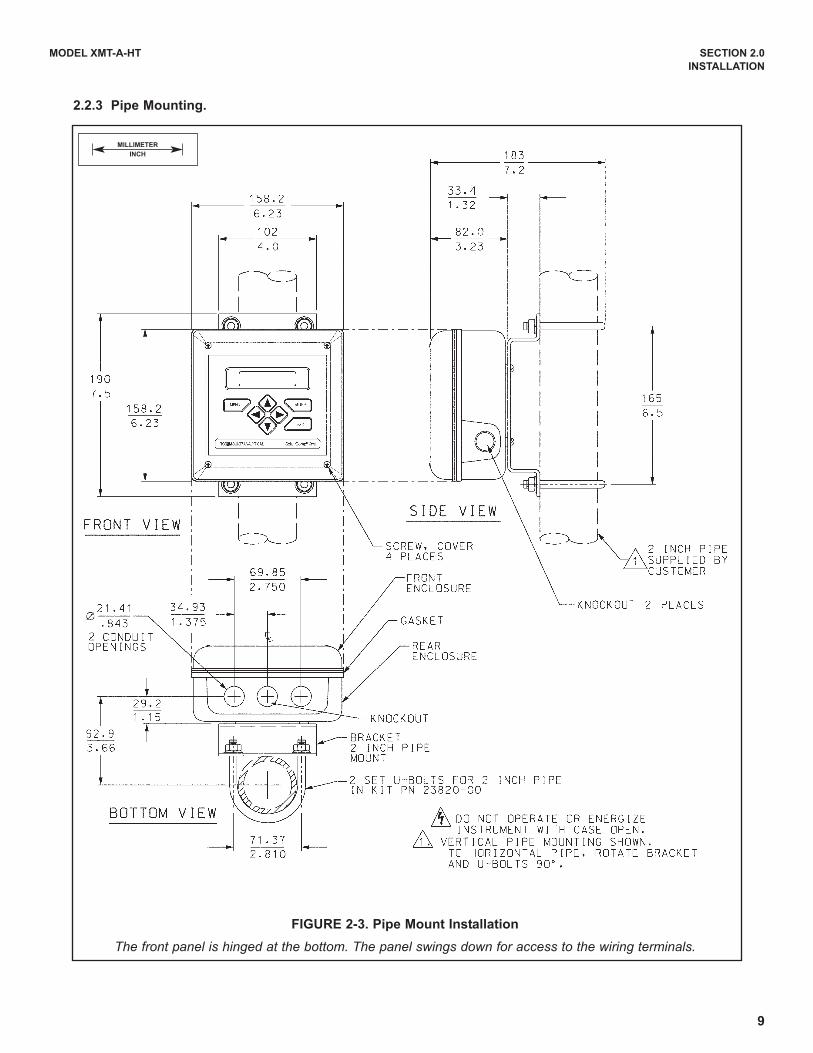
FIGURE 2-3. Pipe Mount Installation
The front panel is hinged at the bottom. The panel swings down for access to the wiring terminals.
2.2.3 Pipe Mounting.
MILLIMETER
INCH

10
MODEL XMT-A-HT SECTION 2.0
INSTALLATION
FIGURE 2-4. Surface Mount Installation
The front panel is hinged at the bottom. The panel swings down for access to the wiring terminals.
2.2.4 Surface Mounting.
MILLIMETER
INCH
11
MODEL XMT-A-HT SECTION 2.0
INSTALLATION
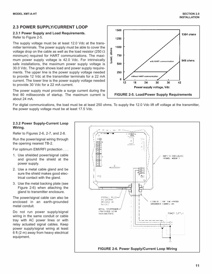
2.3 POWER SUPPLY/CURRENT LOOP
2.3.1 Power Supply and Load Requirements.
Refer to Figure 2-5.
The supply voltage must be at least 12.0 Vdc at the trans-
mitter terminals. The power supply must be able to cover the
voltage drop on the cable as well as the load resistor (250 Ωminimum) required for HART communications. The maxi-
mum power supply voltage is 42.0 Vdc. For intrinsically
safe installations, the maximum power supply voltage is
30.0 Vdc. The graph shows load and power supply require-
ments. The upper line is the power supply voltage needed
to provide 12 Vdc at the transmitter terminals for a 22 mA
current. The lower line is the power supply voltage needed
to provide 30 Vdc for a 22 mA current.
The power supply must provide a surge current during the
first 80 milliseconds of startup. The maximum current is
about 24 mA.
For digital communications, the load must be at least 250 ohms. To supply the 12.0 Vdc lift off voltage at the transmitter,
the power supply voltage must be at least 17.5 Vdc.
FIGURE 2-5. Load/Power Supply Requirements
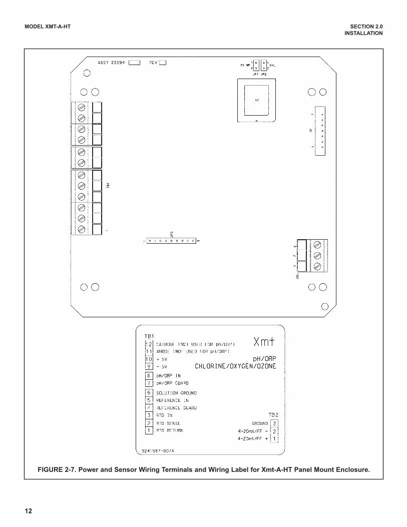
FIGURE 2-6. Power Supply/Current Loop Wiring
2.3.2 Power Supply-Current Loop
Wiring.
Refer to Figures 2-6, 2-7, and 2-8.
Run the power/signal wiring through
the opening nearest TB-2.
For optimum EMI/RFI protection . . .
1. Use shielded power/signal cable
and ground the shield at the
power supply.
2. Use a metal cable gland and be
sure the shield makes good elec-
trical contact with the gland.
3. Use the metal backing plate (see
Figure 2-6) when attaching the
gland to transmitter enclosure.
The power/signal cable can also be
enclosed in an earth-grounded
metal conduit.
Do not run power supply/signal
wiring in the same conduit or cable
tray with AC power lines or with
relay actuated signal cables. Keep
power supply/signal wiring at least
6 ft (2 m) away from heavy electrical
equipment.
12
MODEL XMT-A-HT SECTION 2.0
INSTALLATION
FIGURE 2-7. Power and Sensor Wiring Terminals and Wiring Label for Xmt-A-HT Panel Mount Enclosure.

13
MODEL XMT-A-HT SECTION 2.0
INSTALLATION
FIGURE 2-8. Power and Sensor Wiring Terminals and Wiring Label for Xmt-A-HT Pipe/Surface Mount Enclosure.

14
MODEL XMT-A-HT SECTION 3.0
SENSOR WIRING
SECTION 3.0SENSOR WIRING
3.1 WIRING MODEL 499A OXYGEN, CHLORINE, MONOCHLORAMINE, AND OZONE SENSORS
All 499A sensors (499ADO, 499ATrDO, 499ACL-01, 499ACL-02, 499ACL-03, and 499AOZ) have identical wiring.
Use the pigtail wire and wire nuts provided with the sensor when more than one wire must be attached to a single termi-nal.
FIGURE 33. Xmt-A-HT wall/pipe mount; 499A sen-sors with standard cable
FIGURE 3-4. Xmt-A-HT wall/pipe mount; 499A sen-sors with optimum EMI/RFI or Variopol cable
FIGURE 3-1. Xmt-A-HT panel mount; 499A sensorswith standard cable
FIGURE 3-2. Xmt-A-HT panel mount; 499A sensorswith optimum EMI/RFI or Variopol cable
15
MODEL XMT-A-HT SECTION 3.0
SENSOR WIRING
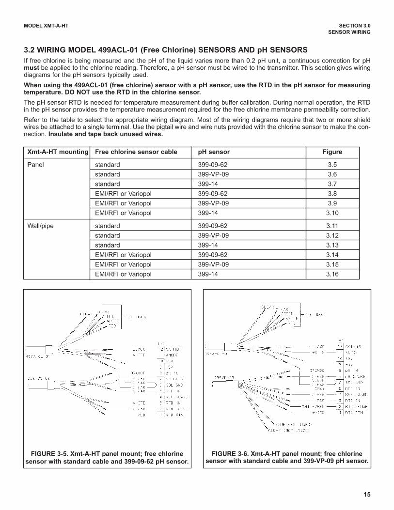
FIGURE 3-5. Xmt-A-HT panel mount; free chlorine
sensor with standard cable and 399-09-62 pH sensor.
FIGURE 3-6. Xmt-A-HT panel mount; free chlorinesensor with standard cable and 399-VP-09 pH sensor.
Xmt-A-HT mounting Free chlorine sensor cable pH sensor Figure
Panel standard 399-09-62 3.5
standard 399-VP-09 3.6
standard 399-14 3.7
EMI/RFI or Variopol 399-09-62 3.8
EMI/RFI or Variopol 399-VP-09 3.9
EMI/RFI or Variopol 399-14 3.10
Wall/pipe standard 399-09-62 3.11
standard 399-VP-09 3.12
standard 399-14 3.13
EMI/RFI or Variopol 399-09-62 3.14
EMI/RFI or Variopol 399-VP-09 3.15
EMI/RFI or Variopol 399-14 3.16
3.2 WIRING MODEL 499ACL-01 (Free Chlorine) SENSORS AND pH SENSORS
If free chlorine is being measured and the pH of the liquid varies more than 0.2 pH unit, a continuous correction for pHmust be applied to the chlorine reading. Therefore, a pH sensor must be wired to the transmitter. This section gives wiringdiagrams for the pH sensors typically used.
When using the 499ACL-01 (free chlorine) sensor with a pH sensor, use the RTD in the pH sensor for measuringtemperature. DO NOT use the RTD in the chlorine sensor.
The pH sensor RTD is needed for temperature measurement during buffer calibration. During normal operation, the RTDin the pH sensor provides the temperature measurement required for the free chlorine membrane permeability correction.
Refer to the table to select the appropriate wiring diagram. Most of the wiring diagrams require that two or more shieldwires be attached to a single terminal. Use the pigtail wire and wire nuts provided with the chlorine sensor to make the con-nection. Insulate and tape back unused wires.
16
MODEL XMT-A-HT SECTION 3.0
SENSOR WIRING
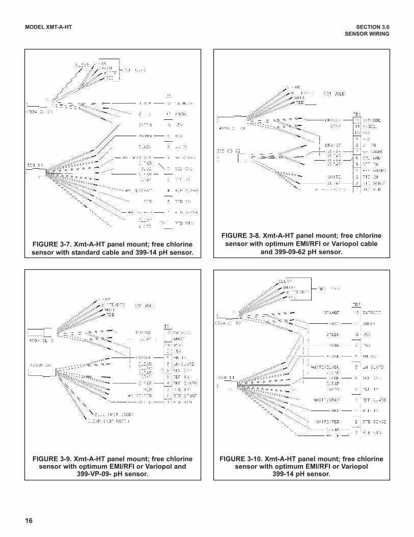
FIGURE 3-9. Xmt-A-HT panel mount; free chlorinesensor with optimum EMI/RFI or Variopol and
399-VP-09- pH sensor.
FIGURE 3-10. Xmt-A-HT panel mount; free chlorinesensor with optimum EMI/RFI or Variopol
399-14 pH sensor.
FIGURE 3-7. Xmt-A-HT panel mount; free chlorine
sensor with standard cable and 399-14 pH sensor.
FIGURE 3-8. Xmt-A-HT panel mount; free chlorine
sensor with optimum EMI/RFI or Variopol cable
and 399-09-62 pH sensor.
17
MODEL XMT-A-HT SECTION 3.0
SENSOR WIRING
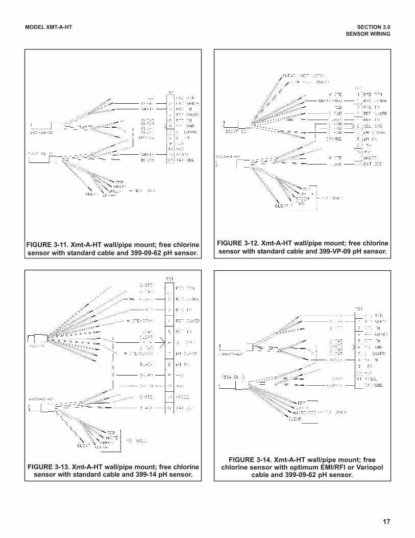
FIGURE 3-13. Xmt-A-HT wall/pipe mount; free chlorinesensor with standard cable and 399-14 pH sensor.
FIGURE 3-14. Xmt-A-HT wall/pipe mount; freechlorine sensor with optimum EMI/RFI or Variopol
cable and 399-09-62 pH sensor.
FIGURE 3-11. Xmt-A-HT wall/pipe mount; free chlorine
sensor with standard cable and 399-09-62 pH sensor.
FIGURE 3-12. Xmt-A-HT wall/pipe mount; free chlorine
sensor with standard cable and 399-VP-09 pH sensor.
18
MODEL XMT-A-HT SECTION 3.0
SENSOR WIRING
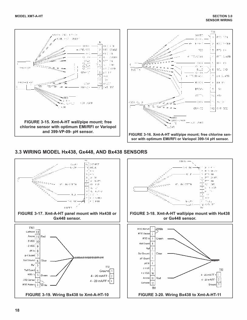
FIGURE 3-15. Xmt-A-HT wall/pipe mount; free
chlorine sensor with optimum EMI/RFI or Variopol
and 399-VP-09- pH sensor.FIGURE 3-16. Xmt-A-HT wall/pipe mount; free chlorine sen-
sor with optimum EMI/RFI or Variopol 399-14 pH sensor.
FIGURE 3-17. Xmt-A-HT panel mount with Hx438 or
Gx448 sensor.
FIGURE 3-18. Xmt-A-HT wall/pipe mount with Hx438
or Gx448 sensor.
FIGURE 3-19. Wiring Bx438 to Xmt-A-HT-10 FIGURE 3-20. Wiring Bx438 to Xmt-A-HT-11
3.3 WIRING MODEL Hx438, Gx448, AND Bx438 SENSORS

19
MODEL XMT-A-HT SECTION 4.0
INTRINSICALLY SAFE OPERATION
FIG
UR
E 4
-1.
FM
In
trin
sic
ally S
afe
In
sta
llati
on
Lab
el
SECTION 4.0INTRINSICALLY SAFE OPERATION

20
MODEL XMT-A-HT SECTION 4.0
INTRINSICALLY SAFE OPERATION
FIG
UR
E 4
-2.
FM
In
trin
sic
ally S
afe
In
sta
llati
on
Wir
ing
(1 o
f 2)

21
MODEL XMT-A-HT SECTION 4.0
INTRINSICALLY SAFE OPERATION
FIG
UR
E 4
-2.
FM
In
trin
sic
ally S
afe
In
sta
llati
on
Wir
ing
(2 o
f 2)
22
MODEL XMT-A-HT SECTION 4.0
INTRINSICALLY SAFE OPERATION
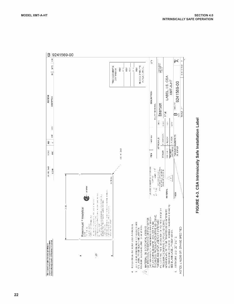
FIG
UR
E 4
-3.
CS
A I
ntr
insic
ally S
afe
In
sta
llati
on
Lab
el

23
MODEL XMT-A-HT SECTION 4.0
INTRINSICALLY SAFE OPERATION
FIG
UR
E 4
-4.
CS
A I
ntr
insic
ally S
afe
In
sta
llati
on
Wir
ing
(1 o
f 2)
24
MODEL XMT-A-HT SECTION 4.0
INTRINSICALLY SAFE OPERATION
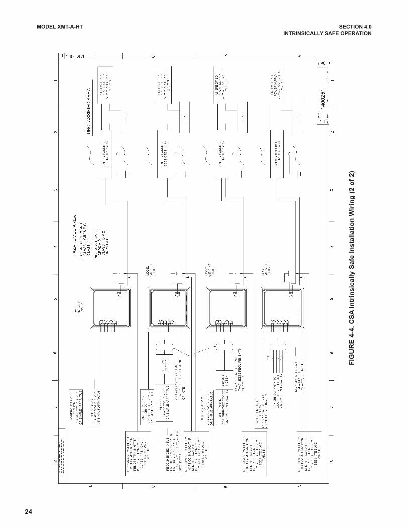
FIG
UR
E 4
-4.
CS
A I
ntr
insic
ally S
afe
In
sta
llati
on
Wir
ing
(2 o
f 2)

25
MODEL XMT-A-HT SECTION 4.0
INTRINSICALLY SAFE OPERATION
FIG
UR
E 4
-5.
Baseefa
/AT
EX
In
trin
sic
ally S
afe
In
sta
llati
on
Lab
el
26
MODEL XMT-A-HT SECTION 4.0
INTRINSICALLY SAFE OPERATION
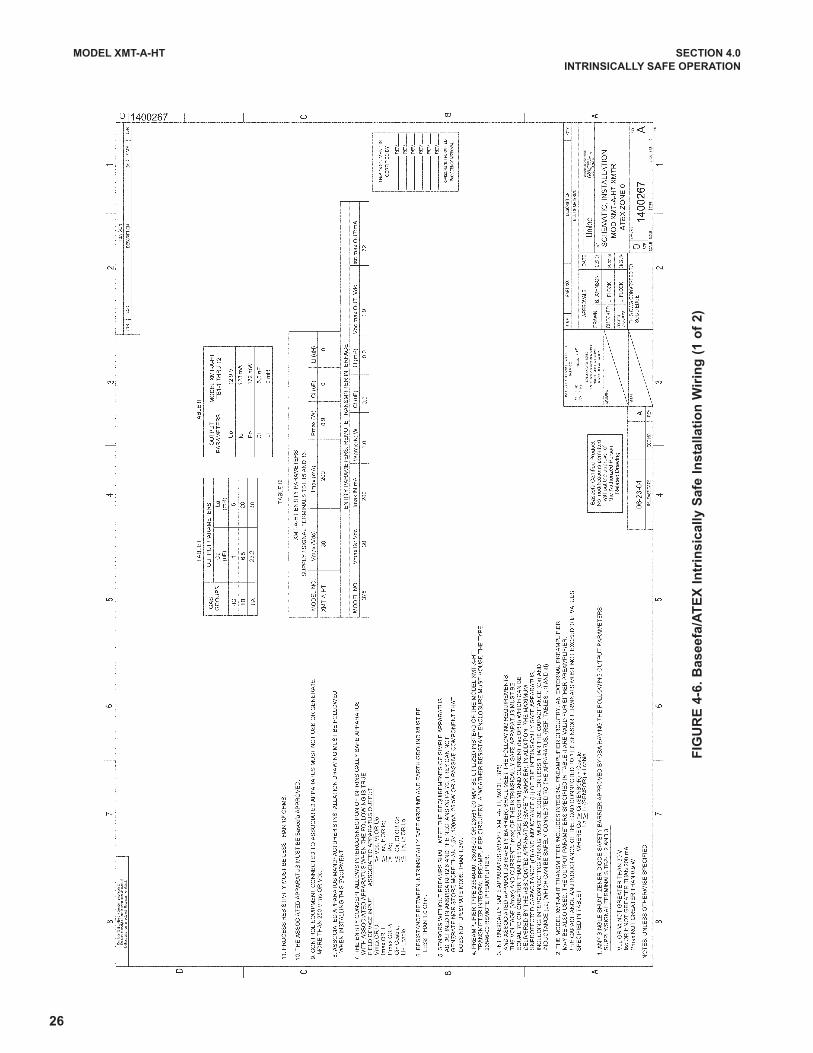
FIG
UR
E 4
-6.
Baseefa
/AT
EX
In
trin
sic
ally S
afe
In
sta
llati
on
Wir
ing
(1 o
f 2)

27
MODEL XMT-A-HT SECTION 4.0
INTRINSICALLY SAFE OPERATION
FIG
UR
E 4
-6.
Baseefa
/AT
EX
In
trin
sic
ally S
afe
In
sta
llati
on
Wir
ing
(2 o
f 2)
28
MODEL XMT-A-HT SECTION 5.0
DISPLAY AND OPERATION
SECTION 5.0DISPLAY AND OPERATION
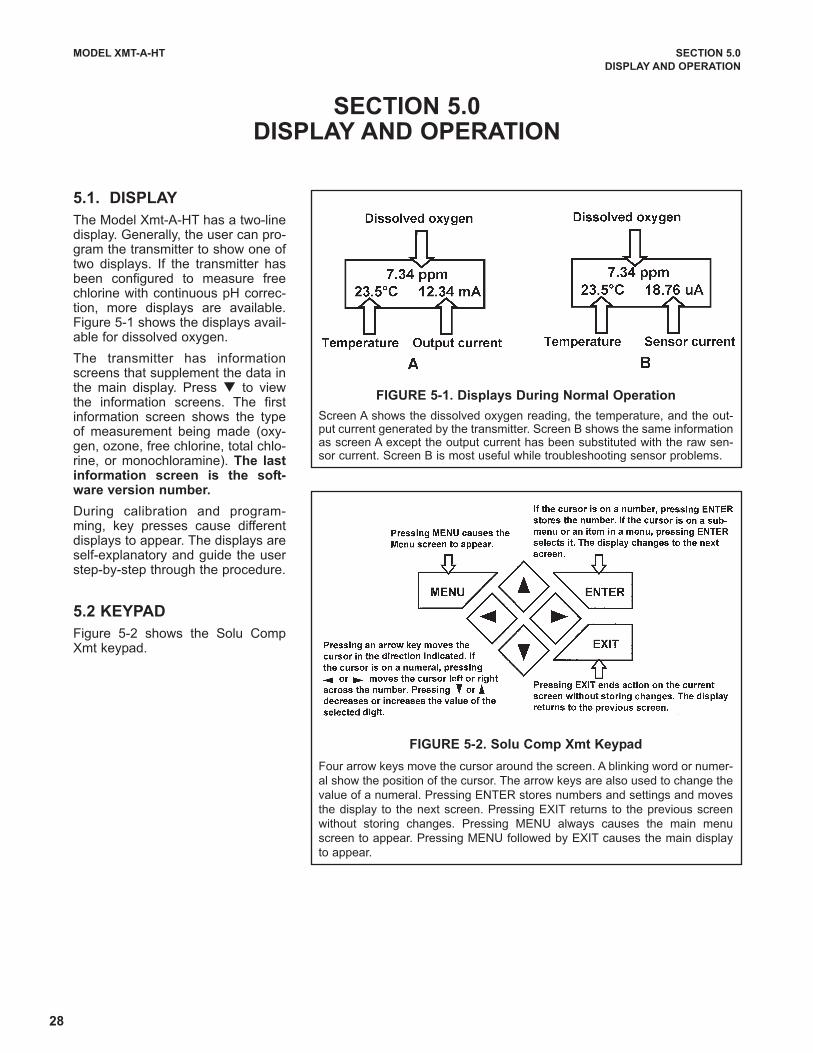
5.1. DISPLAY
The Model Xmt-A-HT has a two-linedisplay. Generally, the user can pro-gram the transmitter to show one oftwo displays. If the transmitter hasbeen configured to measure freechlorine with continuous pH correc-tion, more displays are available.Figure 5-1 shows the displays avail-able for dissolved oxygen.
The transmitter has informationscreens that supplement the data inthe main display. Press q to viewthe information screens. The firstinformation screen shows the typeof measurement being made (oxy-gen, ozone, free chlorine, total chlo-rine, or monochloramine). The lastinformation screen is the soft-ware version number.
During calibration and program-ming, key presses cause differentdisplays to appear. The displays areself-explanatory and guide the userstep-by-step through the procedure.
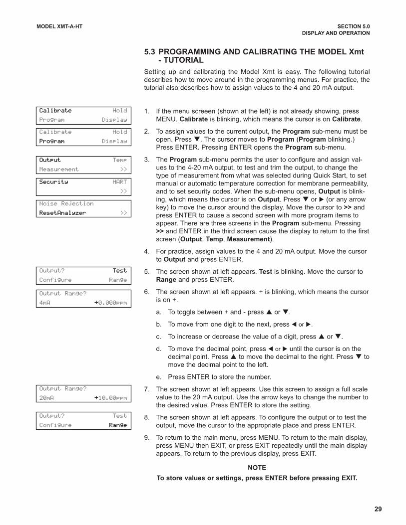
5.2 KEYPAD
Figure 5-2 shows the Solu CompXmt keypad.
FIGURE 5-1. Displays During Normal Operation
Screen A shows the dissolved oxygen reading, the temperature, and the out-put current generated by the transmitter. Screen B shows the same informationas screen A except the output current has been substituted with the raw sen-sor current. Screen B is most useful while troubleshooting sensor problems.
FIGURE 5-2. Solu Comp Xmt Keypad
Four arrow keys move the cursor around the screen. A blinking word or numer-
al show the position of the cursor. The arrow keys are also used to change the
value of a numeral. Pressing ENTER stores numbers and settings and moves
the display to the next screen. Pressing EXIT returns to the previous screen
without storing changes. Pressing MENU always causes the main menu
screen to appear. Pressing MENU followed by EXIT causes the main display
to appear.
29
MODEL XMT-A-HT SECTION 5.0
DISPLAY AND OPERATION
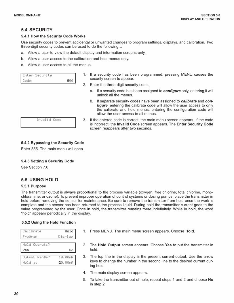
5.3 PROGRAMMING AND CALIBRATING THE MODEL Xmt- TUTORIAL
Setting up and calibrating the Model Xmt is easy. The following tutorial
describes how to move around in the programming menus. For practice, the
tutorial also describes how to assign values to the 4 and 20 mA output.
1. If the menu screeen (shown at the left) is not already showing, press
MENU. Calibrate is blinking, which means the cursor is on Calibrate.
2. To assign values to the current output, the Program sub-menu must be
open. Press q. The cursor moves to Program (Program blinking.)
Press ENTER. Pressing ENTER opens the Program sub-menu.
3. The Program sub-menu permits the user to configure and assign val-
ues to the 4-20 mA output, to test and trim the output, to change the
type of measurement from what was selected during Quick Start, to set
manual or automatic temperature correction for membrane permeability,
and to set security codes. When the sub-menu opens, Output is blink-
ing, which means the cursor is on Output. Press q or u (or any arrow
key) to move the cursor around the display. Move the cursor to >> and
press ENTER to cause a second screen with more program items to
appear. There are three screens in the Program sub-menu. Pressing
>> and ENTER in the third screen cause the display to return to the first
screen (Output, Temp, Measurement).
4. For practice, assign values to the 4 and 20 mA output. Move the cursor
to Output and press ENTER.
5. The screen shown at left appears. Test is blinking. Move the cursor to
Range and press ENTER.
6. The screen shown at left appears. + is blinking, which means the cursor
is on +.
a. To toggle between + and - press p or q.
b. To move from one digit to the next, press t or u.
c. To increase or decrease the value of a digit, press p or q.
d. To move the decimal point, press t or u until the cursor is on the
decimal point. Press p to move the decimal to the right. Press q to
move the decimal point to the left.
e. Press ENTER to store the number.
7. The screen shown at left appears. Use this screen to assign a full scale
value to the 20 mA output. Use the arrow keys to change the number to
the desired value. Press ENTER to store the setting.
8. The screen shown at left appears. To configure the output or to test the
output, move the cursor to the appropriate place and press ENTER.
9. To return to the main menu, press MENU. To return to the main display,
press MENU then EXIT, or press EXIT repeatedly until the main display
appears. To return to the previous display, press EXIT.
NOTE
To store values or settings, press ENTER before pressing EXIT.
Calibrate Hold
Program Display
Calibrate Hold
Program Display
Output Temp
Measurement >>
Security HART
>>
Output Range?
20mA +10.00ppm
Noise Rejection
ResetAnalyzer >>
Output Range?
4mA +0.000ppm
Output? Test
Configure Range
Output? Test
Configure Range
30
MODEL XMT-A-HT SECTION 5.0
DISPLAY AND OPERATION
1. If a security code has been programmed, pressing MENU causes thesecurity screen to appear.
2. Enter the three-digit security code.
a. If a security code has been assigned to configure only, entering it willunlock all the menus.
b. If separate security codes have been assigned to calibrate and con-figure, entering the calibrate code will allow the user access to onlythe calibrate and hold menus; entering the configuration code willallow the user access to all menus.
3. If the entered code is correct, the main menu screen appears. If the codeis incorrect, the Invalid Code screen appears. The Enter Security Codescreen reappears after two seconds.
Enter Security
Code: 000
Invalid Code
Calibrate Hold
Program Display
Hold Outputs?
Yes No
5.4 SECURITY
5.4.1 How the Security Code Works
Use security codes to prevent accidental or unwanted changes to program settings, displays, and calibration. Twothree-digit security codes can be used to do the following…
a. Allow a user to view the default display and information screens only.
b. Allow a user access to the calibration and hold menus only.
c. Allow a user access to all the menus.
5.4.2 Bypassing the Security Code
Enter 555. The main menu will open.
5.4.3 Setting a Security Code
See Section 7.6.
5.5 USING HOLD
5.5.1 Purpose
The transmitter output is always proportional to the process variable (oxygen, free chlorine, total chlorine, mono-chloramine, or ozone). To prevent improper operation of control systems or dosing pumps, place the transmitter inhold before removing the sensor for maintenance. Be sure to remove the transmitter from hold once the work iscomplete and the sensor has been returned to the process liquid. During hold the transmitter current goes to thevalue programmed by the user. Once in hold, the transmitter remains there indefinitely. While in hold, the word"hold" appears periodically in the display.
5.5.2 Using the Hold Function
1. Press MENU. The main menu screen appears. Choose Hold.
2. The Hold Output screen appears. Choose Yes to put the transmitter in
hold.
3. The top line in the display is the present current output. Use the arrow
keys to change the number in the second line to the desired current dur-
ing hold.
4. The main display screen appears.
5. To take the transmitter out of hole, repeat steps 1 and 2 and choose No
in step 2.
Output Range? 10.00mA
Hold at 20.00mA

31
MODEL XMT-A-HT SECTION 6.0
OPERATION WITH MODEL 375
SECTION 6.0OPERATION WITH MODEL 375
6.1 Note on Model 375 HART Communicator
The Model 375 HART Communicator is a product of Emerson Process Management, Rosemount Inc. This section
contains selected information on using the Model 375 with the Rosemount Analytical Model Xmt-A-HT Transmitter.
For complete information on the Model 375 Communicator, see the Model 375 instruction manual. For technical
support on the Model 375 Communicator, call Rosemount Inc. at (800) 999-9307 within the United States. Support
is available worldwide on the internet at http://rosemount.com.
6.2 Connecting the HART Communicator
Figure 6-1 shows how the Model 275 or 375 HART Communicator con-
nects to the output lines from the Model Xmt-A-HT Transmitter.CAUTION
For intrinsically safe CSA and FM
wiring connections, see the Model
375 instruction manual.
FIGURE 6-1. Connecting the HART Communicator
32
6.3 Operation
6.3.1 Off-line and On-line Operation
The Model 375 Communicator features off-line and on-line communications. On-line means the communicator is
connected to the transmitter in the usual fashion. While the communicator is on line, the operator can view meas-
urement data, change program settings, and read diagnostic messages. Off-line means the communicator is not
connected to the transmitter. When the communicator is off line, the operator can still program settings into the
communicator. Later, after the communicator has been connected to a transmitter, the operator can transfer the
programmed settings to the transmitter. Off-line operation permits settings common to several transmitters to be
easily stored in all of them.
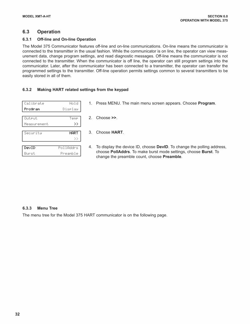
6.3.2 Making HART related settings from the keypad
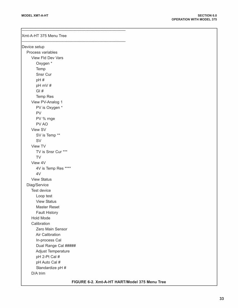
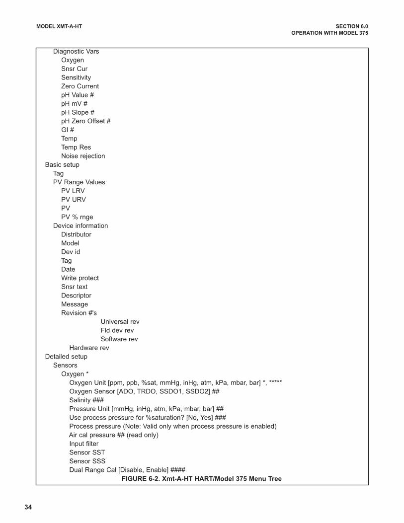
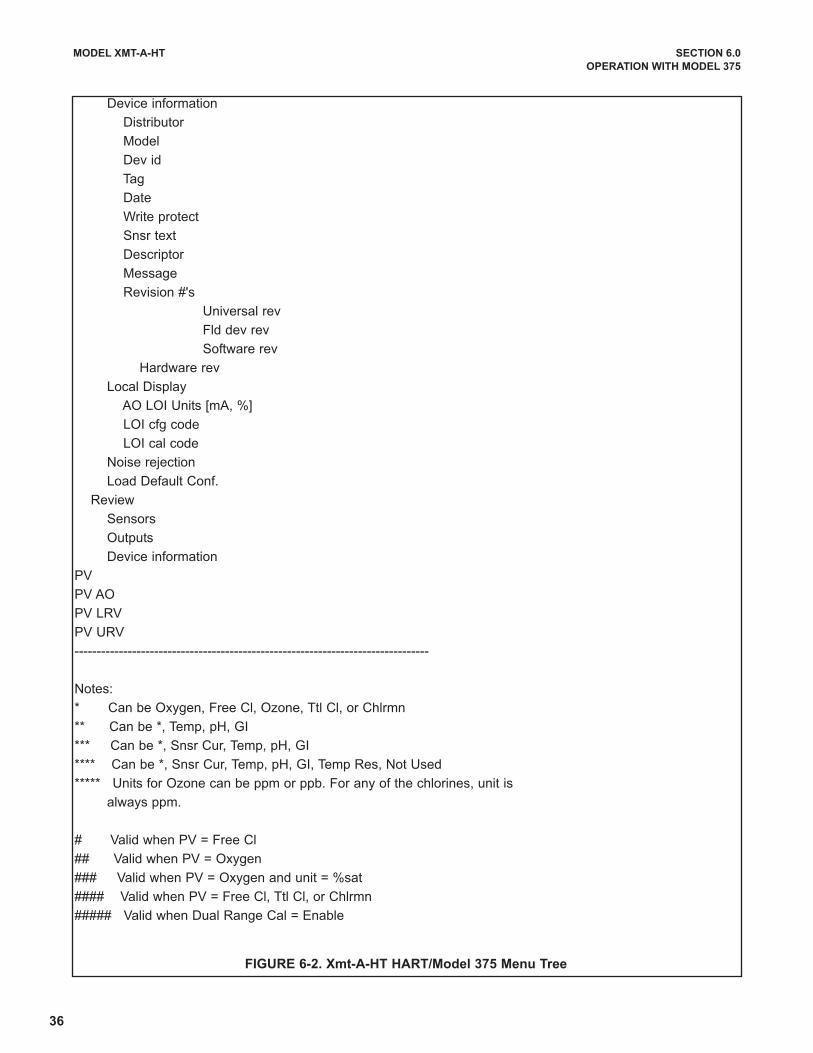
6.3.3 Menu Tree
The menu tree for the Model 375 HART communicator is on the following page.
1. Press MENU. The main menu screen appears. Choose Program.
2. Choose >>.
3. Choose HART.
4. To display the device ID, choose DevID. To change the polling address,
choose PollAddrs. To make burst mode settings, choose Burst. To
change the preamble count, choose Preamble.
MODEL XMT-A-HT SECTION 6.0
OPERATION WITH MODEL 375
Calibrate Hold
Program Display
Output Temp
Measurement >>
Security HART
>>
DevID PollAddrs
Burst Preamble
33
MODEL XMT-A-HT SECTION 6.0
OPERATION WITH MODEL 375
--------------------------------------------------------------------------------
Xmt-A-HT 375 Menu Tree
--------------------------------------------------------------------------------
Device setup
Process variables
View Fld Dev Vars
Oxygen *
Temp
Snsr Cur
pH #
pH mV #
GI #
Temp Res
View PV-Analog 1
PV is Oxygen *
PV
PV % rnge
PV AO
View SV
SV is Temp **
SV
View TV
TV is Snsr Cur ***
TV
View 4V
4V is Temp Res ****
4V
View Status
Diag/Service
Test device
Loop test
View Status
Master Reset
Fault History
Hold Mode
Calibration
Zero Main Sensor
Air Calibration
In-process Cal
Dual Range Cal #####
Adjust Temperature
pH 2-Pt Cal #
pH Auto Cal #
Standardize pH #
D/A trim
FIGURE 6-2. Xmt-A-HT HART/Model 375 Menu Tree
34
MODEL XMT-A-HT SECTION 6.0
OPERATION WITH MODEL 375
Diagnostic Vars
Oxygen
Snsr Cur
Sensitivity
Zero Current
pH Value #
pH mV #
pH Slope #
pH Zero Offset #
GI #
Temp
Temp Res
Noise rejection
Basic setup
Tag
PV Range Values
PV LRV
PV URV
PV
PV % rnge
Device information
Distributor
Model
Dev id
Tag
Date
Write protect
Snsr text
Descriptor
Message
Revision #'s
Universal rev
Fld dev rev
Software rev
Hardware rev
Detailed setup
Sensors
Oxygen *
Oxygen Unit [ppm, ppb, %sat, mmHg, inHg, atm, kPa, mbar, bar] *, *****
Oxygen Sensor [ADO, TRDO, SSDO1, SSDO2] ##
Salinity ###
Pressure Unit [mmHg, inHg, atm, kPa, mbar, bar] ##
Use process pressure for %saturation? [No, Yes] ###
Process pressure (Note: Valid only when process pressure is enabled)
Air cal pressure ## (read only)
Input filter
Sensor SST
Sensor SSS
Dual Range Cal [Disable, Enable] ####
FIGURE 6-2. Xmt-A-HT HART/Model 375 Menu Tree

35
MODEL XMT-A-HT SECTION 6.0
OPERATION WITH MODEL 375
pH #
pH Value
pH Comp [Auto, Manual]
Manual pH
Preamp loc [Sensor, Xmtr]
Autocal [Manual, Standard, DIN 19267, Ingold, Merck]
pH Slope
pH SST
pH SSS
pH Zero Offset Limit
pH Diagnostics
Diagnostics [Off, On]
GFH
GFL
Imped Comp [Off, On]
Temperature
Temp Comp [Auto, Manual]
Man. Temp
Temp unit [ºC, ºF]
Temp Snsr
Signal condition
LRV
URV
AO Damp
% rnge
Xfer fnctn
AO lo end point
AO hi end pt
Output condition
Analog output
AO
AO Alrm typ
Fixed
Fault mode [Fixed, Live]
Fault
Loop test
D/A trim
HART output
PV is Oxygen *
SV is Temp **
TV is Snsr Cur ***
4V is pH ****
Poll addr
Burst option [PV, %range/current, Process vars/crnt]
Burst mode [Off, On]
Num req preams
Num resp preams
FIGURE 6-2. Xmt-A-HT HART/Model 375 Menu Tree
36
MODEL XMT-A-HT SECTION 6.0
OPERATION WITH MODEL 375
Device information
Distributor
Model
Dev id
Tag
Date
Write protect
Snsr text
Descriptor
Message
Revision #'s
Universal rev
Fld dev rev
Software rev
Hardware rev
Local Display
AO LOI Units [mA, %]
LOI cfg code
LOI cal code
Noise rejection
Load Default Conf.
Review
Sensors
Outputs
Device information
PV
PV AO
PV LRV
PV URV
--------------------------------------------------------------------------------
Notes:
* Can be Oxygen, Free Cl, Ozone, Ttl Cl, or Chlrmn
** Can be *, Temp, pH, GI
*** Can be *, Snsr Cur, Temp, pH, GI
**** Can be *, Snsr Cur, Temp, pH, GI, Temp Res, Not Used
***** Units for Ozone can be ppm or ppb. For any of the chlorines, unit is
always ppm.
# Valid when PV = Free Cl
## Valid when PV = Oxygen
### Valid when PV = Oxygen and unit = %sat
#### Valid when PV = Free Cl, Ttl Cl, or Chlrmn
##### Valid when Dual Range Cal = Enable
FIGURE 6-2. Xmt-A-HT HART/Model 375 Menu Tree
37
MODEL XMT-A-HT SECTION 7.0
PROGRAMMING THE TRANSMITTER
SECTION 7.0PROGRAMMING THE TRANSMITTER
7.1 GENERAL
This section describes how to program the transmitter using the keypad.
1. Configure and assign values to the 4-20 mA output.
2. Test and trim the current output.
3. Select the measurement to be made (oxygen, ozone, free chlorine, total chlorine, or monochloramine).
4. Choose temperature units and automatic or manual temperature mode.
5. Set a security code.
6. Make certain settings relating to HART communication.
7. Program the transmitter for maximum reduction of environmental noise.
Default settings are shown in Table 7-1. To change a default setting, refer to the section listed in the table. To return the
transmitter to the default settings, see Section 7.9.
7.2 CHANGING START-UP SETTINGS
When the Solu Comp Xmt is powered up for the first time, startup screens appear. The screens prompt the user to
enter the measurement being made and if oxygen was selected, to identify the sensor being used, to select automat-
ic or manual pH correction (free chlorine only) and to select temperature units. If incorrect settings were entered at
startup, enter the correct settings now. To change the measurement, refer to Section 7.4.

38
TABLE 7-1. Default Settings
MODEL XMT-A-HT SECTION 7.0
PROGRAMMING THE TRANSMITTER
Table 7-1 continued on following page

39
MODEL XMT-A-HT SECTION 7.0
PROGRAMMING THE TRANSMITTER
7.3 CONFIGURING AND RANGING THE OUTPUT
7.3.1 Purpose
1. Configuring an output means
a. displaying the output reading in units of mA or percent of full scale.
b. changing the time constant for output dampening.
c. assigning the value the output current will take if the transmitter detects a fault in itself or the sensor.
2. Ranging the output means assigning values to the 4 mA and 20 mA outputs.
3. Testing an output means entering a test value from the keypad to check the operation of recorders or controllers.
4. Trimming an output means calibrating the 4 and 20 mA current outputs against a referee milliammeter.
7.3.2 Definitions
1. CURRENT OUTPUT. The transmitter provides a continuous 4-20 mA output current directly proportional to the
concentration of oxygen, ozone, chlorine, or monochloramine in the sample.
2. FAULT. The transmitter continuously monitors itself and the sensor for faults. If the transmitter detects a fault, the
4-20 mA output can be programmed to go to a fixed value or it can be programmed to continue to display the live
current reading. In any event Fault appears intermittently in the second line of the display.
3. DAMPEN. Output dampening smooths out noisy readings. But it also increases the response time of the output. To
estimate the time (in minutes) required for the output to reach 95% of the final reading following a step change, divide
the setting by 20. Thus, a setting of 140 means that, following a step change, the output takes about seven minutes
to reach 95% of final reading. The output dampen setting does not affect the response time of the process display. The
maximum setting is 255.
4. TEST. The transmitter can be programmed to generate a test current.
TABLE 7-1. Default Settings (continued)

40
MODEL XMT-A-HT SECTION 7.0
PROGRAMMING THE TRANSMITTER
7.3.3 Procedure: Configuring the Output
1. Press MENU. The menu screen appears. Choose Program.
2. Choose Output.
3. Choose Configure.
4. Choose Fault.
5. Choose Fixed or Live.
6. If you chose Fixed, the screen at left appears. Use the arrow keys to change the
fault current to the desired value. The limits are 4.00 to 22.00 mA. If you chose
Live, there are no settings to make.
7. The screen at left appears. Choose mA/%.
8. Choose mA or percent. Percent means the display will show percent of full scale
reading.
9. The screen at left appears. Choose Damping.
10. Use the arrow keys to change the blinking display to the desired time constant.
1. Press MENU. The menu screen appears. Choose Program.
2. Choose Output.
3. Choose Range.
4. Assign a value to the 4 mA output and press ENTER. Then assign a value to the
20 mA output. Press ENTER. Use the arrow keys to change the flashing display
to the desired value.
Calibrate Hold
Program Display
Display Ouput?
mA percent
Output Temp
Measurement° >>
Configure? Fault
mA/% Damping
Configure? Fault
mA/% Damping
Configure? Fault
mA/% Damping
Set to value?
Fixed Live
Current Output
if Fault:22.00mA
Damping? 000−255
000 sec
Output range?
4mA 0.000ppm
Output? Test
Configure Range
Output Temp
Measurement° >>
Output? Test
Configure Range
7.3.4 Procedure: Ranging the output
Calibrate Hold
Program Display

41
MODEL XMT-A-HT SECTION 7.0
PROGRAMMING THE TRANSMITTER
Current Output
for Test:12.00mA
Output Temp
Measurement° >>
Test Output
Trim Output
Output? Test
Configure Range
7.3.5 Procedure: Testing the output
Calibrate Hold
Program Display
1. Press MENU. The menu screen appears. Choose Program.
2. Choose Output.
3. Choose Test.
4. Choose Test Output.
5. Use the arrow keys to change the displayed current to the desired value. Press
ENTER. The output will change to the value just entered.
6. To return to normal operation, press EXIT. The output will return to the value deter-
mined by the process variable.
7. To return to the main display, press MENU then EXIT.
Meter reading:
04.00mA
Meter reading:
20.00mA
Trim Complete
Output Temp
Measurement >>
Test Output
Trim Output
Output? Test
Configure Range
7.3.6 Procedure: Trimming the output
Calibrate Hold
Program Display
1. Connect an accurate milliammeter in series with the current output.
2. Press MENU. The menu screen appears. Choose Program.
3. Choose Output.
4. Choose Test.
5. Choose Trim Output.
6. The output goes to 4.00 mA. If the milliammeter does not read 4.00 mA, use the
arrow keys to change the display to match the current measured by the mil-
liammeter.
7. The output goes to 20.00 mA. If the milliammeter does not read 20.00 mA, use
the arrow keys to change the display to match the current measured by the mil-
liammeter.
8. To return to the main display, press MENU then EXIT.

42
MODEL XMT-A-HT SECTION 7.0
PROGRAMMING THE TRANSMITTER
7.4 CHOOSING AND CONFIGURING THE ANALYTICAL MEASUREMENT
7.4.1 Purpose
This section describes how to do the following:
1. Configure the transmitter to measure oxygen, ozone, free chlorine, total chlorine, or monochloramine.
2. Choose the concentration units to be displayed
3. Set an input filter for the raw sensor current.
4. If oxygen was selected, there are additional selections to make.
a. identify the type of sensor being used
b. choose the units in which barometric pressure will be displayed
c. select a process pressure for calculating % saturation
d. enter the salinity of the process liquid
5. If free chlorine was selected, there are additional selections and settings to make.
a. choose automatic or manual pH correction
b. configure the pH sensor if automatic pH correction was selected
c. choose single or dual slope calibration
6. If total chlorine was selected, single or dual slope calibration must also be specified.
7.4.2 Definitions
1. MEASUREMENT. The transmitter can be configured to measure dissolve oxygen (ppm and ppb level), free chlorine,
total chlorine, monochloramine, and ozone.
2. FREE CHLORINE. Free chlorine is the product of adding sodium hypochlorite (bleach) or chlorine gas to fresh water.
Free chlorine is the sum of hypochlorous acid (HOCl) and hypochlorite ion (OCl-).
3. TOTAL CHLORINE. Total chlorine is the sum of free and combined chlorine. Combined chlorine generally refers to
chlorine oxidants in which chlorine is combined with ammonia or organic amines. The term total chlorine also refers to
other chlorine oxidants such as chlorine dioxide. To measure total chlorine, the sample must first be treated with acetic
acid and potassium iodide. Total chlorine reacts with iodide to produce an equivalent amount of iodine, which the sen-
sor measures.
4. MONOCHLORAMINE. Monochloramine (NH2Cl) is commonly used in the United States for disinfecting drinking water.
It is made by first treating the water with ammonia followed by just the exact amount of chlorine to completely react
with the ammonia. Monochloramine is a useful disinfectant in waters that have a tendency to produce trihalomethanes
(THMs) when treated free chlorine.
5. BAROMETRIC PRESSURE (DISSOLVED OXYGEN ONLY). Dissolved oxygen sensors are usually calibrated by
exposing them to air. The sensor current in air is exactly the same as the current when the sensor is in water saturat-
ed with air. The maximum solubility of atmospheric oxygen in water depends on temperature and barometric pressure.
A temperature device in the oxygen sensor measures temperature. The user must enter the barometric pressure.
6. PERCENT SATURATION (DISSOLVED OXYGEN ONLY). Percent saturation is the ratio of the concentration of dis-
solved oxygen in a sample to the maximum amount of oxygen the sample can hold at the same temperature. Pressure
also affects the percent saturation. Usually, percent saturation is calculated using the barometric pressure during cal-
ibration. If the user desires, percent saturation can also be calculated using the process pressure.
43
7. SALINITY (DISSOLVED OXYGEN ONLY). The solubility of oxygen in water depends on the concentration of dis-
solved salts in water. Increasing the concentration decreases the solubility. If the salt concentration is greater than
about 1000 ppm, the accuracy of the measurement can be improved by applying a salinity correction. Enter the salin-
ity as parts per thousand. One percent is ten parts per thousand.
8. pH CORRECTION (FREE CHLORINE ONLY). Free chlorine is the sum of hypochlorous acid (HOCl) and hypochlorite
ion (OCl-). The relative amount of each depends on pH. As pH increases, the fraction of free chlorine present as HOCl
decreases and the fraction present as OCl- increases. Because the sensor responds only to HOCl, a correction is nec-
essary to convert the sensor current into a free chlorine reading. The Solu Comp Xmt uses both automatic and man-
ual pH correction. In automatic pH correction the transmitter continuously monitors the pH of the sample and corrects
the free chlorine reading for changes in pH. In manual pH correction, the user enters the pH of the sample. Generally,
if the pH varies more than about 0.2 units over short periods of time, automatic pH correction is best. If the pH is rel-
atively steady or subject only to seasonal changes, manual pH correction is adequate.
9. pH SETTINGS (FREE CHLORINE ONLY). If you are measuring free chlorine with continuous (automatic) pH correc-
tion, there are additional pH settings to make.
a. PREAMPLIFIER. The raw pH signal is a high impedance voltage. A voltage follower or preamplifier, located either
in the sensor or transmitter, converts the high impedance signal into a low impedance one. Normally, high imped-
ance signals should be sent no further than about 15 feet.
b. REFERENCE OFFSET. Ideally, a pH sensor in pH 7 buffer should have a voltage of 0 mV. The difference between
the measured voltage in pH 7 buffer and the ideal value is the reference offset. Typically, the reference offset is
less than 60 mV.
c. DIAGNOSTICS. The Solu Comp Xmt continuously monitors the pH sensor for faults. If it detects a fault, the trans-
mitter displays a fault message.
d. GLASS IMPEDANCE. The transmitter monitors the condition of the pH-sensitive glass membrane in the sensor by
continuously measuring the impedance across the membrane. Typical impedance is between 100 and 500 MΩ.
Low impedance (<10 MΩ) implies the glass bulb has cracked and the sensor must be replaced. An extremely high
impedance (>1000 MΩ) implirs the sensor is aging and may soon need replacement. High impedance might also
mean that the glass membrane is no longer immersed in the process liquid.
10. DUAL SLOPE CALIBRATION (FREE AND TOTAL CHLORINE ONLY). The Model 499ACL-01 (free chlorine) and
499ACL-02 (total chlorine) sensors lose sensitivity at high concentrations of chlorine. The Solu Comp Xmt has a dual
slope feature that allows the user to compensate for the non-linearity of the sensor. For the vast majority of applica-
tions, dual slope calibration is unnecessary.
11. INPUT FILTER. The raw sensor current can be filtered to reduce noise. Filtering also increases the response time. The
filter is the time required for the input to reach 63% of its final reading following a step change.
MODEL XMT-A-HT SECTION 7.0
PROGRAMMING THE TRANSMITTER

44
MODEL XMT-A-HT SECTION 7.0
PROGRAMMING THE TRANSMITTER
Manufacturer?
Rosemount Other
Application?
Water/Waste >>
units?
ppm %sat ppb >>
units?
ppm ppb
Pressure units?
mmHg inHg atm >>
Use processPress
for %satn? Yes No
Process pressure
%sat: 760mmHg
Input filter?
63% in 005sec
Input filter?
63% in 005sec
Salinity, parts/
thousand? 20.0
Outputs Temp
Measurement° >>
Measurement type
Oxygen Ozone >>
7.4.3 Procedure: Measurement
Calibrate Hold
Program Display
1. Press MENU. The menu screen appears. Choose Program.
2. Choose Measurement.
3. Choose Measurement type (oxygen, ozone, free chlorine, total chlorine, ormonochloramine).
4. The screen appearing next depends on the selection made in step 3.
a. If you chose oxygen, go to step 5a.
b. If you chose ozone, go to step 6a.
c. If you chose free chlorine, go to step 7a.
d. If you chose total chlorine, go to step 8a.
e. If you chose monochloramine, go to step 9a.
5a. Identify the manufacturer of the oxygen sensor: Rosemount or Other.
5b. Identify the application: water or wastewater, trace oxygen, or biopharm. Movethe cursor to >> and press ENTER to move to the next screen.
5c. Choose the units in which results are to be displayed: ppm, ppb, partialPress, or%sat. Select >> to view the next screen. If you chose partialPress, the partialpressure and the barometric pressure used in air calibration will be displayed inthe pressure units selected below.
5d. Choose pressure units: mm Hg, in Hg, atm, kPa, bar, or mbar.
5e. If percent saturation is to be calculated using the process pressure, choose Yesand go to step 5f. If percent saturation is to be calculated using the barometricpressure during air calibration, choose No. If you chose No, the screen changesto the screen in step 5g.
5f. Enter the desired pressure.
5g. Enter the time constant for the input filter.
5h. Enter the salinity in parts per thousand.
5i. To return to the main display press MENU then EXIT.
6a. If you chose ozone, select the units in which the ozone concentration is to be displayed.
6b. Enter the time constant for the input filter.
6c. To return to the main display, press MENU then EXIT.

45
MODEL XMT-A-HT SECTION 7.0
PROGRAMMING THE TRANSMITTER
7a. For free chlorine, choose auto or manual pH correction. If you chose auto,
you must also configure the pH sensor. Go to step 7b. If you chose manual, go
to step 7k.
7b. Identify the location of the pre-amplifier for the pH sensor. Is it in the transmitter
(Xmtr) or in the sensor or junction box (Sensor/Jbox)?
pH sensor pre-amplifier location
399-09-62 Sensor/JBox
399VP-09 Sensor/JBox
399-14 Xmtr
7c. Select a maximum value for the pH sensor reference offset.
7d. Activate diagnostic messages. Even if diagnostic messages are turned off, the
current pulses used to measure diagnostics will still be operating.
7e. Turn on or turn off the temperature correction for the glass membrane imped-
ance measurement. Keeping the temperature correction on is recommended.
7f. Select a value at which the low glass impedance fault message will be shown.
The default value is 0010 MΩ.
7g. Select a value at which the high glass impedance fault message will be shown.
The default value is 1000 MΩ.
7h. Enter the time constant for the input filter.
7i. Choose single or dual slope calibration. For the vast majority of applications,
dual slope calibration is unnecessary.
7j. To return to the main display, press MENU then EXIT.
7k. If you choose manual pH correction, enter the desired pH. The transmitter will
use this value in all subsequent calculations no matter what the true pH is.
7l. Enter the time constant for the input filter.
7m.Choose single or dual slope calibration. For the vast majority of applications,
dual slope calibration is unnecessary.
7n. To return to the main display, press MENU then EXIT.
pH Comp?
Auto Manual
Use Preamp in?
Xmtr Sensor/JBox
Cal Slope?
Single Dual
Cal Slope?
Single Dual
Diagnostic msgs?
On Off
GlassZ temp
correct On Off
Glass fault low
value: 0010mΩ
Glass fault high
value: 1000mΩ
Manual pH
07.00pH
Max pH reference
offset: 060mV
Input filter?
63% in 005sec
Input filter?
63% in 005sec

46
MODEL XMT-A-HT SECTION 7.0
PROGRAMMING THE TRANSMITTER
8a. If you chose total chlorine, select single or dual slope calibration. For the vast
majority of applications, dual slope calibration is unnecessary.
8b. Enter the time constant for the input filter.
8c. To return to the main display, press MENU then EXIT.
9a. If you chose monochloramine, enter the time constant for the input filter.
9b. To return to the main display, press MENU then EXIT.
Cl Cal Slope?
Single Dual
7.5 MAKING TEMPERATURE SETTINGS
7.5.1 Purpose
This section describes how to do the following:
1. Choose temperature units (°C or °F).
2. Choose automatic or manual temperature correction for membrane permeability.
3. Choose automatic or manual temperature compensation for pH (pH settings apply to free chlorine only).
4. Enter a temperature for manual temperature compensation.
7.5.2 Definitions — oxygen, ozone, chlorine, and monochloramine
1. AUTOMATIC TEMPERATURE CORRECTION. Membrane-covered amperometric sensors produce a current directly
proportional to the rate the analyte (the substance being measured) diffuses through the membrane. The diffusion
rate is proportional to the concentration of analyte and the temperature. As temperature increases, membrane per-
meability increases. Thus, an increase in temperature will cause the sensor current to increase even though the
analyte level remained constant. A correction equation in the transmitter software automatically corrects for changes
in membrane permeability. In automatic temperature correction, the transmitter uses the temperature measured by
the sensor for the correction.
2. MANUAL TEMPERATURE CORRECTION. In manual temperature correction the transmitter uses the temperature
entered by the user for the membrane permeability correction. It does not use the actual process temperature. Do
NOT use manual temperature correction unless the measurement and calibration temperatures differ by no more
than about 2°C. Manual temperature correction is useful only if the sensor temperature element has failed and a
replacement sensor is not available.
7.5.3 Definitions — pH
1. AUTOMATIC TEMPERATURE COMPENSATION. The transmitter uses a temperature-dependent factor to convert
measured cell voltage to pH. In automatic temperature compensation, the transmitter measures the temperature and
automatically calculates the correct conversion factor. For maximum accuracy, use automatic temperature compen-
sation.
2. MANUAL TEMPERATURE COMPENSATION. In manual temperature compensation, the transmitter converts meas-
ured voltage to pH using the temperature entered by the user. It does not use the actual process temperature. Do
NOT use manual temperature compensation unless the process temperature varies no more than about ±2°C or the
pH is between 6 and 8. Manual temperature compensation is useful if the sensor temperature element has failed
and a replacement sensor is not available.
Input filter?
63% in 005sec
Input filter?
63% in 005sec

47
MODEL XMT-A-HT SECTION 7.0
PROGRAMMING THE TRANSMITTER
Outputs Temp
Measurement >>
Config Temp?
°C/F Live/Manual
7.5.3 Procedure: Temperature settings
Calibrate Hold
Program Display
1. Press MENU. The menu screen appears. Choose Program.
2. Choose Temp.
3. Choose °C/°F to change the display units. Choose Live/Manual to turn on (Live) orturn off (Manual) automatic temperature correction for membrane permeabilityand automatic temperature compensation for pH.
a. If you chose °C/°F, select °C or °F.
b. If you chose Live/Manual, select Live or Manual.
c. If you chose Manual, enter the temperature in the next screen. The tempera-ture entered in this step will be used in all subsequent measurements, no mat-ter what the process temperature is.
4. To return to the main display, press MENU then EXIT.
Outputs Temp
Measurement >>
Security HART
>>
7.6.2 Procedure: Setting a security code
Calibrate Hold
Program Display
Lock?
Calib Config
1. Press MENU. The menu screen appears. Choose Program.
2. Choose >>.
3. Choose Security.
4. Choose Calib or Config.
a. If you chose Calib, enter a three-digit security code.
b. If you chose Config, enter a three-digit security code.
5. To return to the main display, press MENU then EXIT.
7.6 SETTING A SECURITY CODE
7.6.1 Purpose
This section describes how to set a security code. There are three levels of security:
a. A user can view the default display and information screens only.
b. A user has access to the calibration and hold menus only.
c. A user has access to all menus.
The security code is a three-digit number. The table shows what happens when security codes are assigned to Calib(calibration) and Config (configure). In the table XXX and YYY are the assigned security codes. To bypass security,enter 555.
Code assignments
Calib Config What happens
000 XXX User enters XXX and has access to all menus.
XXX YYY User enters XXX and has access to calibration and hold menus only. User enters YYY and has access to all menus.
XXX 000 User needs no security code to have access to all menus.
000 000 User needs no security code to have access to all menus.
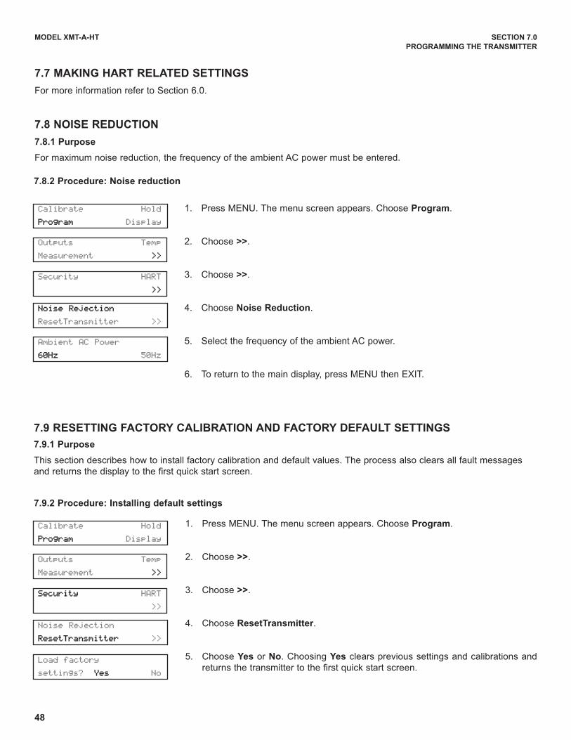
48
MODEL XMT-A-HT SECTION 7.0
PROGRAMMING THE TRANSMITTER
Outputs Temp
Measurement >>
Security HART
>>
7.8.2 Procedure: Noise reduction
Calibrate Hold
Program Display
Ambient AC Power
60Hz 50Hz
Noise Rejection
ResetTransmitter >>
Noise Rejection
ResetTransmitter >>
1. Press MENU. The menu screen appears. Choose Program.
2. Choose >>.
3. Choose >>.
4. Choose Noise Reduction.
5. Select the frequency of the ambient AC power.
6. To return to the main display, press MENU then EXIT.
7.7 MAKING HART RELATED SETTINGS
For more information refer to Section 6.0.
7.8 NOISE REDUCTION
7.8.1 Purpose
For maximum noise reduction, the frequency of the ambient AC power must be entered.
Outputs Temp
Measurement >>
Security HART
>>
Calibrate Hold
Program Display
Load factory
settings? Yes No
1. Press MENU. The menu screen appears. Choose Program.
2. Choose >>.
3. Choose >>.
4. Choose ResetTransmitter.
5. Choose Yes or No. Choosing Yes clears previous settings and calibrations and
returns the transmitter to the first quick start screen.
7.9 RESETTING FACTORY CALIBRATION AND FACTORY DEFAULT SETTINGS
7.9.1 Purpose
This section describes how to install factory calibration and default values. The process also clears all fault messages
and returns the display to the first quick start screen.
7.9.2 Procedure: Installing default settings
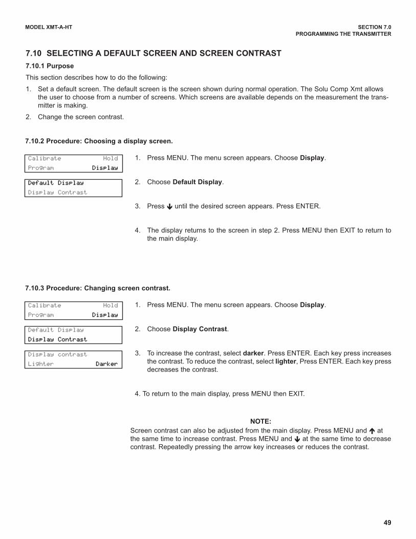
49
Default Display
Display Contrast
7.10.2 Procedure: Choosing a display screen.
Calibrate Hold
Program Display
1. Press MENU. The menu screen appears. Choose Display.
2. Choose Default Display.
3. Press ê until the desired screen appears. Press ENTER.
4. The display returns to the screen in step 2. Press MENU then EXIT to return to
the main display.
7.10 SELECTING A DEFAULT SCREEN AND SCREEN CONTRAST
7.10.1 Purpose
This section describes how to do the following:
1. Set a default screen. The default screen is the screen shown during normal operation. The Solu Comp Xmt allows
the user to choose from a number of screens. Which screens are available depends on the measurement the trans-
mitter is making.
2. Change the screen contrast.
Default Display
Display Contrast
Display contrast
Lighter Darker
7.10.3 Procedure: Changing screen contrast.
Calibrate Hold
Program Display
1. Press MENU. The menu screen appears. Choose Display.
2. Choose Display Contrast.
3. To increase the contrast, select darker. Press ENTER. Each key press increases
the contrast. To reduce the contrast, select lighter, Press ENTER. Each key press
decreases the contrast.
4. To return to the main display, press MENU then EXIT.
MODEL XMT-A-HT SECTION 7.0
PROGRAMMING THE TRANSMITTER
NOTE:
Screen contrast can also be adjusted from the main display. Press MENU and é at
the same time to increase contrast. Press MENU and ê at the same time to decrease
contrast. Repeatedly pressing the arrow key increases or reduces the contrast.
50
MODEL XMT-A-HT SECTION 8.0
CALIBRATION — TEMPERATURE
SECTION 8.0CALIBRATION — TEMPERATURE
8.1 INTRODUCTION
All five amperometric sensors (oxygen, ozone, free chlorine, total chlorine, and monochloramine) are membrane-
covered sensors. As the sensor operates, the analyte (the substance to be determined) diffuses through the mem-
brane and is consumed at an electrode immediately behind the membrane. The reaction produces a current that
depends on the rate at which the analyte diffuses through the membrane. The diffusion rate, in turn, depends on the
concentration of the analyte and how easily it passes through the membrane (the membrane permeability). Because
the membrane permeability is a function of temperature, the sensor current will change if the temperature changes.
To correct for changes in sensor current caused by temperature, the transmitter automatically applies a membrane
permeability correction. Although the membrane permeability is different for each sensor, the change is about 3%/°C
at 25°C, so a 1°C error in temperature produces about a 3% error in the reading.
Temperature plays an additional role in oxygen measurements. Oxygen sensors are calibrated by exposing them
to water-saturated air, which, from the point of view of the sensor, is equivalent to water saturated with atmospheric
oxygen (see Section 9.0 for more information). During calibration, the transmitter calculates the solubility of atmos-
pheric oxygen in water using the following steps. First, the transmitter measures the temperature. From the tem-
perature, the transmitter calculates the vapor pressure of water and, using the barometric pressure, calculates the
partial pressure of atmospheric oxygen. Once the transmitter knows the partial pressure, it calculates the equilib-
rium solubility of oxygen in water using a temperature-dependent factor called the Bunsen coefficient. Overall, a
1°C error in the temperature measurement produces about a 2% error in the solubility calculated during calibra-
tion and about the same error in subsequent measurements.
Temperature is also important in the pH measurement required to correct free chlorine readings.
1. The transmitter uses a temperature dependent factor to convert measured cell voltage to pH. Normally, a slight
inaccuracy in the temperature reading is unimportant unless the pH reading is significantly different from 7.00.
Even then, the error is small. For example, at pH 12 and 25°C, a 1°C error produces a pH error less than ±0.02.
2. During auto calibration, the transmitter recognizes the buffer being used and calculates the actual pH of the
buffer at the measured temperature. Because the pH of most buffers changes only slightly with temperature,
reasonable errors in temperature do not produce large errors in the buffer pH. For example, a 1°C error caus-
es at most an error of ±0.03 in the calculated buffer pH.
Without calibration the accuracy of the temperature measurement is about ±0.4°C. Calibrate the transmitter if
1. ±0.4°C accuracy is not acceptable
2. the temperature measurement is suspected of being in error. Calibrate temperature by making the transmit-
terreading match the temperature measured with a standard thermometer.

51
MODEL XMT-A-HT SECTION 8.0
CALIBRATION — TEMPERATURE
4. Press MENU. The menu screen appears. Choose Calibrate.
5. Choose Temp.
6. If transmitter was programmed in Section 7.5 to use the actual process
temperature, go to step 7.
If the transmitter was programmed to use a temperature entered by the
user, go to step 9.
7. To calibrate the temperature, change the number in the second line to
match the temperature measured with the standard thermometer.
Press ENTER.
8. Press MENU then EXIT to return to the main display.
9. If the temperature value shown in the display is not correct, use the
arrow keys to change it to the desired value. The transmitter will use the
temperature entered in this step in all measurements and calculations,
no matter what the true temperature is.
10. Press MENU then EXIT to return to the main display.
8.2 PROCEDURE: CALIBRATING TEMPERATURE
1. Remove the sensor from the process liquid. Place it in an insulated container of water along with a calibrated
thermometer. Submerge at least the bottom two inches of the sensor. Stir continuously.
2. Allow the sensor to reach thermal equilibrium. For some sensors, the time constant for a change in tempera-
ture is 5 min., so it may take as long as 30 min. for temperature equilibration.
3. Change the Solu Comp Xmt display to match the calibrated thermometer using the procedure below.
Cal?
Measurement Temp
Calibrate Hold
Program Display
Live 25.0ºC
Cal +025.0ºC
Manual Temp?
+25.0ºC
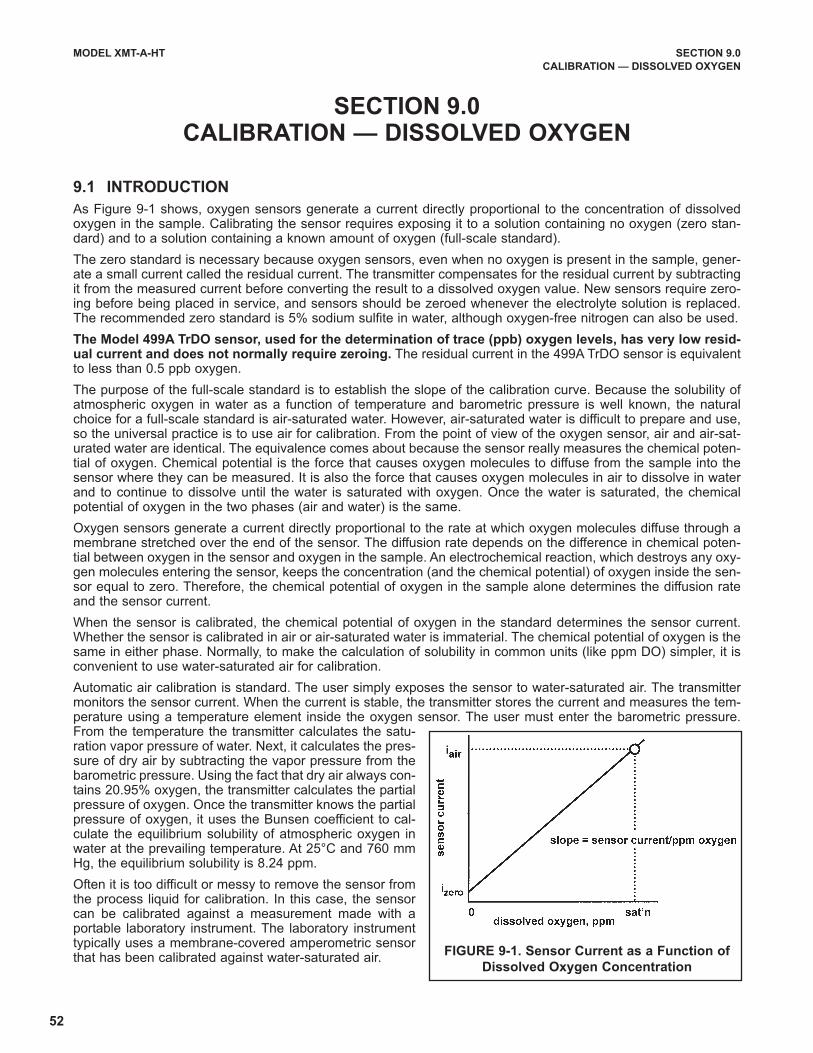
52
MODEL XMT-A-HT SECTION 9.0
CALIBRATION — DISSOLVED OXYGEN
SECTION 9.0CALIBRATION — DISSOLVED OXYGEN
9.1 INTRODUCTION
As Figure 9-1 shows, oxygen sensors generate a current directly proportional to the concentration of dissolvedoxygen in the sample. Calibrating the sensor requires exposing it to a solution containing no oxygen (zero stan-dard) and to a solution containing a known amount of oxygen (full-scale standard).
The zero standard is necessary because oxygen sensors, even when no oxygen is present in the sample, gener-ate a small current called the residual current. The transmitter compensates for the residual current by subtractingit from the measured current before converting the result to a dissolved oxygen value. New sensors require zero-ing before being placed in service, and sensors should be zeroed whenever the electrolyte solution is replaced.The recommended zero standard is 5% sodium sulfite in water, although oxygen-free nitrogen can also be used.
The Model 499A TrDO sensor, used for the determination of trace (ppb) oxygen levels, has very low resid-ual current and does not normally require zeroing. The residual current in the 499A TrDO sensor is equivalentto less than 0.5 ppb oxygen.
The purpose of the full-scale standard is to establish the slope of the calibration curve. Because the solubility ofatmospheric oxygen in water as a function of temperature and barometric pressure is well known, the naturalchoice for a full-scale standard is air-saturated water. However, air-saturated water is difficult to prepare and use,so the universal practice is to use air for calibration. From the point of view of the oxygen sensor, air and air-sat-urated water are identical. The equivalence comes about because the sensor really measures the chemical poten-tial of oxygen. Chemical potential is the force that causes oxygen molecules to diffuse from the sample into thesensor where they can be measured. It is also the force that causes oxygen molecules in air to dissolve in waterand to continue to dissolve until the water is saturated with oxygen. Once the water is saturated, the chemicalpotential of oxygen in the two phases (air and water) is the same.
Oxygen sensors generate a current directly proportional to the rate at which oxygen molecules diffuse through amembrane stretched over the end of the sensor. The diffusion rate depends on the difference in chemical poten-tial between oxygen in the sensor and oxygen in the sample. An electrochemical reaction, which destroys any oxy-gen molecules entering the sensor, keeps the concentration (and the chemical potential) of oxygen inside the sen-sor equal to zero. Therefore, the chemical potential of oxygen in the sample alone determines the diffusion rateand the sensor current.
When the sensor is calibrated, the chemical potential of oxygen in the standard determines the sensor current.Whether the sensor is calibrated in air or air-saturated water is immaterial. The chemical potential of oxygen is thesame in either phase. Normally, to make the calculation of solubility in common units (like ppm DO) simpler, it isconvenient to use water-saturated air for calibration.
Automatic air calibration is standard. The user simply exposes the sensor to water-saturated air. The transmittermonitors the sensor current. When the current is stable, the transmitter stores the current and measures the tem-perature using a temperature element inside the oxygen sensor. The user must enter the barometric pressure.From the temperature the transmitter calculates the satu-ration vapor pressure of water. Next, it calculates the pres-sure of dry air by subtracting the vapor pressure from thebarometric pressure. Using the fact that dry air always con-tains 20.95% oxygen, the transmitter calculates the partialpressure of oxygen. Once the transmitter knows the partialpressure of oxygen, it uses the Bunsen coefficient to cal-culate the equilibrium solubility of atmospheric oxygen inwater at the prevailing temperature. At 25°C and 760 mmHg, the equilibrium solubility is 8.24 ppm.
Often it is too difficult or messy to remove the sensor fromthe process liquid for calibration. In this case, the sensorcan be calibrated against a measurement made with aportable laboratory instrument. The laboratory instrumenttypically uses a membrane-covered amperometric sensorthat has been calibrated against water-saturated air.
FIGURE 9-1. Sensor Current as a Function of
Dissolved Oxygen Concentration
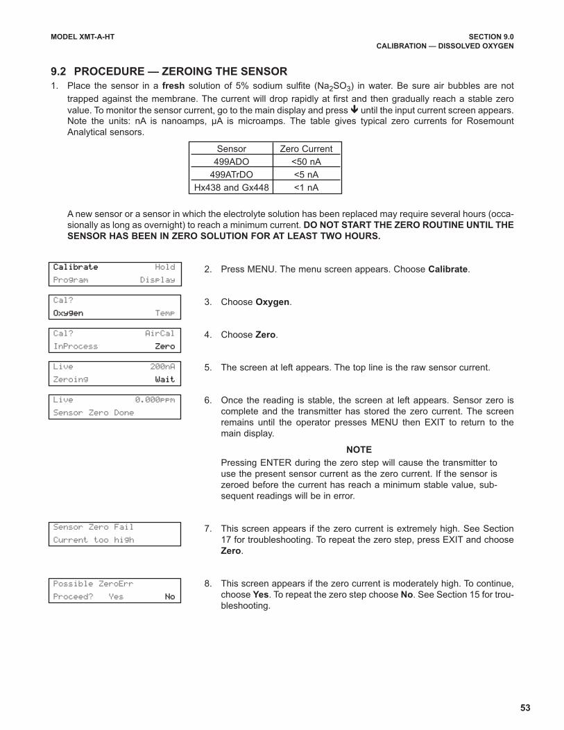
53
MODEL XMT-A-HT SECTION 9.0
CALIBRATION — DISSOLVED OXYGEN
2. Press MENU. The menu screen appears. Choose Calibrate.
3. Choose Oxygen.
4. Choose Zero.
5. The screen at left appears. The top line is the raw sensor current.
6. Once the reading is stable, the screen at left appears. Sensor zero is
complete and the transmitter has stored the zero current. The screen
remains until the operator presses MENU then EXIT to return to the
main display.
NOTE
Pressing ENTER during the zero step will cause the transmitter to
use the present sensor current as the zero current. If the sensor is
zeroed before the current has reach a minimum stable value, sub-
sequent readings will be in error.
7. This screen appears if the zero current is extremely high. See Section
17 for troubleshooting. To repeat the zero step, press EXIT and choose
Zero.
8. This screen appears if the zero current is moderately high. To continue,
choose Yes. To repeat the zero step choose No. See Section 15 for trou-
bleshooting.
9.2 PROCEDURE — ZEROING THE SENSOR
1. Place the sensor in a fresh solution of 5% sodium sulfite (Na2SO3) in water. Be sure air bubbles are not
trapped against the membrane. The current will drop rapidly at first and then gradually reach a stable zero
value. To monitor the sensor current, go to the main display and press ê until the input current screen appears.Note the units: nA is nanoamps, µA is microamps. The table gives typical zero currents for Rosemount
Analytical sensors.
A new sensor or a sensor in which the electrolyte solution has been replaced may require several hours (occa-
sionally as long as overnight) to reach a minimum current. DO NOT START THE ZERO ROUTINE UNTIL THE
SENSOR HAS BEEN IN ZERO SOLUTION FOR AT LEAST TWO HOURS.
Sensor Zero Current
499ADO <50 nA
499ATrDO <5 nA
Hx438 and Gx448 <1 nA
Cal?
Oxygen Temp
Cal? AirCal
InProcess Zero
Live 200nA
Zeroing Wait
Possible ZeroErr
Proceed? Yes No
Live 0.000ppm
Sensor Zero Done
Sensor Zero Fail
Current too high
Calibrate Hold
Program Display
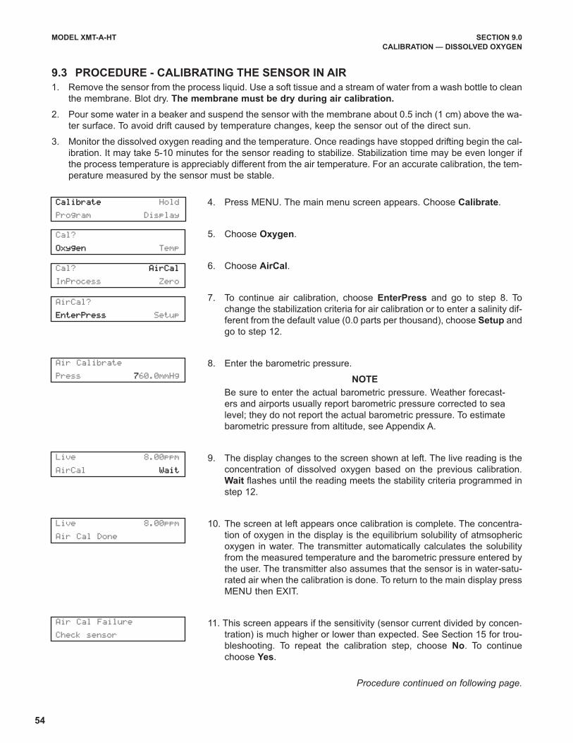
54
MODEL XMT-A-HT SECTION 9.0
CALIBRATION — DISSOLVED OXYGEN
4. Press MENU. The main menu screen appears. Choose Calibrate.
5. Choose Oxygen.
6. Choose AirCal.
7. To continue air calibration, choose EnterPress and go to step 8. To
change the stabilization criteria for air calibration or to enter a salinity dif-
ferent from the default value (0.0 parts per thousand), choose Setup and
go to step 12.
8. Enter the barometric pressure.
NOTE
Be sure to enter the actual barometric pressure. Weather forecast-
ers and airports usually report barometric pressure corrected to sea
level; they do not report the actual barometric pressure. To estimate
barometric pressure from altitude, see Appendix A.
9. The display changes to the screen shown at left. The live reading is the
concentration of dissolved oxygen based on the previous calibration.
Wait flashes until the reading meets the stability criteria programmed in
step 12.
10. The screen at left appears once calibration is complete. The concentra-
tion of oxygen in the display is the equilibrium solubility of atmsopheric
oxygen in water. The transmitter automatically calculates the solubility
from the measured temperature and the barometric pressure entered by
the user. The transmitter also assumes that the sensor is in water-satu-
rated air when the calibration is done. To return to the main display press
MENU then EXIT.
11. This screen appears if the sensitivity (sensor current divided by concen-
tration) is much higher or lower than expected. See Section 15 for trou-
bleshooting. To repeat the calibration step, choose No. To continue
choose Yes.
Procedure continued on following page.
9.3 PROCEDURE - CALIBRATING THE SENSOR IN AIR
1. Remove the sensor from the process liquid. Use a soft tissue and a stream of water from a wash bottle to clean
the membrane. Blot dry. The membrane must be dry during air calibration.
2. Pour some water in a beaker and suspend the sensor with the membrane about 0.5 inch (1 cm) above the wa-
ter surface. To avoid drift caused by temperature changes, keep the sensor out of the direct sun.
3. Monitor the dissolved oxygen reading and the temperature. Once readings have stopped drifting begin the cal-
ibration. It may take 5-10 minutes for the sensor reading to stabilize. Stabilization time may be even longer if
the process temperature is appreciably different from the air temperature. For an accurate calibration, the tem-
perature measured by the sensor must be stable.
Cal? AirCal
InProcess Zero
AirCal?
EnterPress Setup
Calibrate Hold
Program Display
Air Calibrate
Press 760.0mmHg
Live 8.00ppm
AirCal Wait
Live 8.00ppm
Air Cal Done
Air Cal Failure
Check sensor
Cal?
Oxygen Temp
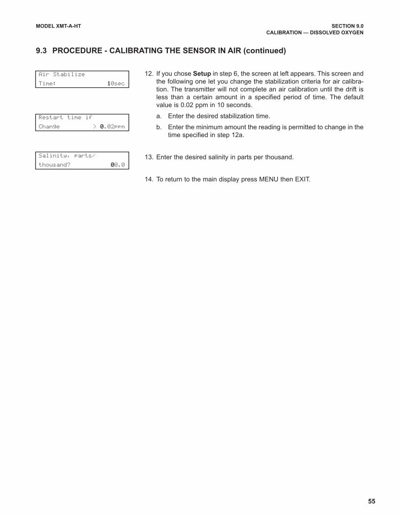
55
MODEL XMT-A-HT SECTION 9.0
CALIBRATION — DISSOLVED OXYGEN
12. If you chose Setup in step 6, the screen at left appears. This screen and
the following one let you change the stabilization criteria for air calibra-
tion. The transmitter will not complete an air calibration until the drift is
less than a certain amount in a specified period of time. The default
value is 0.02 ppm in 10 seconds.
a. Enter the desired stabilization time.
b. Enter the minimum amount the reading is permitted to change in the
time specified in step 12a.
13. Enter the desired salinity in parts per thousand.
14. To return to the main display press MENU then EXIT.
9.3 PROCEDURE - CALIBRATING THE SENSOR IN AIR (continued)
Air Stabilize
Time: 10sec
Restart time if
Change > 0.02ppm
Salinity, parts/
thousand? 00.0
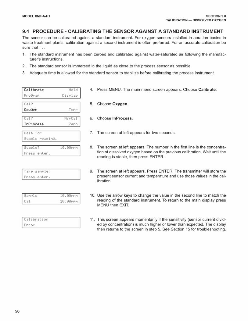
56
MODEL XMT-A-HT SECTION 9.0
CALIBRATION — DISSOLVED OXYGEN
4. Press MENU. The main menu screen appears. Choose Calibrate.
5. Choose Oxygen.
6. Choose InProcess.
7. The screen at left appears for two seconds.
8. The screen at left appears. The number in the first line is the concentra-
tion of dissolved oxygen based on the previous calibration. Wait until the
reading is stable, then press ENTER.
9. The screen at left appears. Press ENTER. The transmitter will store the
present sensor current and temperature and use those values in the cal-
ibration.
10. Use the arrow keys to change the value in the second line to match the
reading of the standard instrument. To return to the main display press
MENU then EXIT.
11. This screen appears momentarily if the sensitivity (sensor current divid-
ed by concentration) is much higher or lower than expected. The display
then returns to the screen in step 5. See Section 15 for troubleshooting.
9.4 PROCEDURE - CALIBRATING THE SENSOR AGAINST A STANDARD INSTRUMENT
The sensor can be calibrated against a standard instrument. For oxygen sensors installed in aeration basins in
waste treatment plants, calibration against a second instrument is often preferred. For an accurate calibration be
sure that . . .
1. The standard instrument has been zeroed and calibrated against water-saturated air following the manufac-
turer's instructions.
2. The standard sensor is immersed in the liquid as close to the process sensor as possible.
3. Adequate time is allowed for the standard sensor to stabilize before calibrating the process instrument.
Cal? AirCal
InProcess Zero
Wait for
Stable reading.
Calibrate Hold
Program Display
Stable? 10.00ppm
Press enter.
Take sample;
Press enter.
Sample 10.00ppm
Cal 10.00ppm
Calibration
Error
Cal?
Oxygen Temp
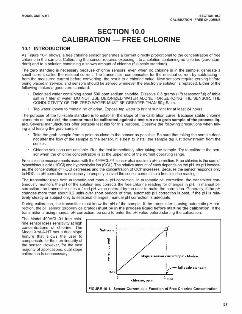
57
10.1 INTRODUCTION
As Figure 10-1 shows, a free chlorine sensor generates a current directly proportional to the concentration of freechlorine in the sample. Calibrating the sensor requires exposing it to a solution containing no chlorine (zero stan-dard) and to a solution containing a known amount of chlorine (full-scale standard).
The zero standard is necessary because chlorine sensors, even when no chlorine is in the sample, generate asmall current called the residual current. The transmitter compensates for the residual current by subtracting itfrom the measured current before converting the result to a chlorine value. New sensors require zeroing beforebeing placed in service, and sensors should be zeroed whenever the electrolyte solution is replaced. Either of thefollowing makes a good zero standard:
• Deionized water containing about 500 ppm sodium chloride. Dissolve 0.5 grams (1/8 teaspoonful) of tablesalt in 1 liter of water. DO NOT USE DEIONIZED WATER ALONE FOR ZEROING THE SENSOR. THECONDUCTIVITY OF THE ZERO WATER MUST BE GREATER THAN 50 μS/cm.
• Tap water known to contain no chlorine. Expose tap water to bright sunlight for at least 24 hours.
The purpose of the full-scale standard is to establish the slope of the calibration curve. Because stable chlorinestandards do not exist, the sensor must be calibrated against a test run on a grab sample of the process liq-uid. Several manufacturers offer portable test kits for this purpose. Observe the following precautions when tak-ing and testing the grab sample.
• Take the grab sample from a point as close to the sensor as possible. Be sure that taking the sample doesnot alter the flow of the sample to the sensor. It is best to install the sample tap just downstream from thesensor.
• Chlorine solutions are unstable. Run the test immediately after taking the sample. Try to calibrate the sen-sor when the chlorine concentration is at the upper end of the normal operating range.
Free chlorine measurements made with the 499ACL-01 sensor also require a pH correction. Free chlorine is the sum ofhypochlorous acid (HOCl) and hyprochlorite ion (OCl-). The relative amount of each depends on the pH. As pH increas-es, the concentration of HOCl decreases and the concentration of OCl- increases. Because the sensor responds onlyto HOCl, a pH correction is necessary to properly convert the sensor current into a free chlorine reading.
The transmitter uses both automatic and manual pH correction. In automatic pH correction, the transmitter con-tinuously monitors the pH of the solution and corrects the free chlorine reading for changes in pH. In manual pHcorrection, the transmitter uses a fixed pH value entered by the user to make the correction. Generally, if the pHchanges more than about 0.2 units over short periods of time, automatic pH correction is best. If the pH is rela-tively steady or subject only to seasonal changes, manual pH correction is adequate.
During calibration, the transmitter must know the pH of the sample. If the transmitter is using automatic pH cor-rection, the pH sensor (properly calibrated) must be in the process liquid before starting the calibration. If thetransmitter is using manual pH correction, be sure to enter the pH value before starting the calibration.
The Model 499ACL-01 free chlo-rine sensor loses sensitivity at highconcentrations of chlorine. TheModel Xmt-A-HT has a dual slopefeature that allows the user tocompensate for the non-linearity ofthe sensor. However, for the vastmajority of applications, dual slopecalibration is unnecessary.
MODEL XMT-A-HT SECTION 10.0
CALIBRATION - FREE CHLORINE
SECTION 10.0CALIBRATION — FREE CHLORINE
FIGURE 10-1. Sensor Current as a Function of Free Chlorine Concentration
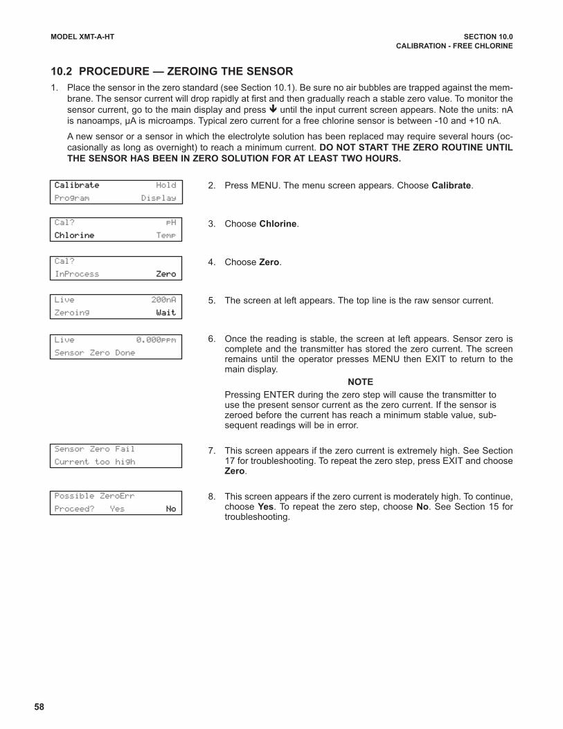
58
MODEL XMT-A-HT SECTION 10.0
CALIBRATION - FREE CHLORINE
10.2 PROCEDURE — ZEROING THE SENSOR
1. Place the sensor in the zero standard (see Section 10.1). Be sure no air bubbles are trapped against the mem-
brane. The sensor current will drop rapidly at first and then gradually reach a stable zero value. To monitor the
sensor current, go to the main display and press ê until the input current screen appears. Note the units: nA
is nanoamps, µA is microamps. Typical zero current for a free chlorine sensor is between -10 and +10 nA.
A new sensor or a sensor in which the electrolyte solution has been replaced may require several hours (oc-
casionally as long as overnight) to reach a minimum current. DO NOT START THE ZERO ROUTINE UNTIL
THE SENSOR HAS BEEN IN ZERO SOLUTION FOR AT LEAST TWO HOURS.
2. Press MENU. The menu screen appears. Choose Calibrate.
3. Choose Chlorine.
4. Choose Zero.
5. The screen at left appears. The top line is the raw sensor current.
6. Once the reading is stable, the screen at left appears. Sensor zero iscomplete and the transmitter has stored the zero current. The screenremains until the operator presses MENU then EXIT to return to themain display.
NOTE
Pressing ENTER during the zero step will cause the transmitter touse the present sensor current as the zero current. If the sensor iszeroed before the current has reach a minimum stable value, sub-sequent readings will be in error.
7. This screen appears if the zero current is extremely high. See Section17 for troubleshooting. To repeat the zero step, press EXIT and chooseZero.
8. This screen appears if the zero current is moderately high. To continue,choose Yes. To repeat the zero step, choose No. See Section 15 fortroubleshooting.
Cal? pH
Chlorine Temp
Cal?
InProcess Zero
Live 200nA
Zeroing Wait
Sensor Zero Fail
Current too high
Possible ZeroErr
Proceed? Yes No
Calibrate Hold
Program Display
Live 0.000ppm
Sensor Zero Done
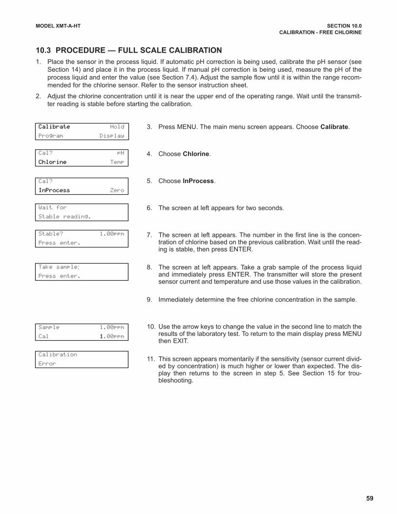
59
MODEL XMT-A-HT SECTION 10.0
CALIBRATION - FREE CHLORINE
10.3 PROCEDURE — FULL SCALE CALIBRATION
1. Place the sensor in the process liquid. If automatic pH correction is being used, calibrate the pH sensor (see
Section 14) and place it in the process liquid. If manual pH correction is being used, measure the pH of the
process liquid and enter the value (see Section 7.4). Adjust the sample flow until it is within the range recom-
mended for the chlorine sensor. Refer to the sensor instruction sheet.
2. Adjust the chlorine concentration until it is near the upper end of the operating range. Wait until the transmit-
ter reading is stable before starting the calibration.
3. Press MENU. The main menu screen appears. Choose Calibrate.
4. Choose Chlorine.
5. Choose InProcess.
6. The screen at left appears for two seconds.
7. The screen at left appears. The number in the first line is the concen-tration of chlorine based on the previous calibration. Wait until the read-ing is stable, then press ENTER.
8. The screen at left appears. Take a grab sample of the process liquidand immediately press ENTER. The transmitter will store the presentsensor current and temperature and use those values in the calibration.
9. Immediately determine the free chlorine concentration in the sample.
10. Use the arrow keys to change the value in the second line to match theresults of the laboratory test. To return to the main display press MENUthen EXIT.
11. This screen appears momentarily if the sensitivity (sensor current divid-ed by concentration) is much higher or lower than expected. The dis-play then returns to the screen in step 5. See Section 15 for trou-bleshooting.
Cal? pH
Chlorine Temp
Calibrate Hold
Program Display
Cal?
InProcess Zero
Wait for
Stable reading.
Stable? 1.00ppm
Press enter.
Take sample;
Press enter.
Sample 1.00ppm
Cal 1.00ppm
Calibration
Error
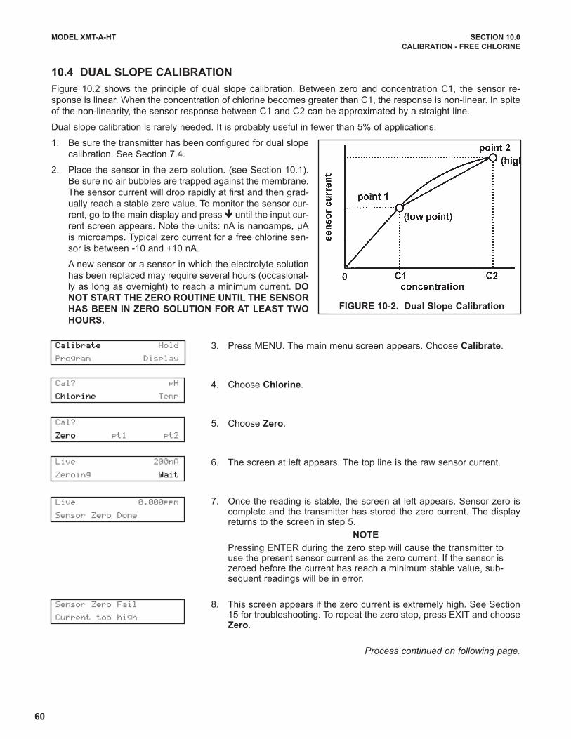
60
MODEL XMT-A-HT SECTION 10.0
CALIBRATION - FREE CHLORINE
10.4 DUAL SLOPE CALIBRATION
Figure 10.2 shows the principle of dual slope calibration. Between zero and concentration C1, the sensor re-
sponse is linear. When the concentration of chlorine becomes greater than C1, the response is non-linear. In spite
of the non-linearity, the sensor response between C1 and C2 can be approximated by a straight line.
Dual slope calibration is rarely needed. It is probably useful in fewer than 5% of applications.
1. Be sure the transmitter has been configured for dual slope
calibration. See Section 7.4.
2. Place the sensor in the zero solution. (see Section 10.1).
Be sure no air bubbles are trapped against the membrane.
The sensor current will drop rapidly at first and then grad-
ually reach a stable zero value. To monitor the sensor cur-
rent, go to the main display and press ê until the input cur-
rent screen appears. Note the units: nA is nanoamps, µA
is microamps. Typical zero current for a free chlorine sen-
sor is between -10 and +10 nA.
A new sensor or a sensor in which the electrolyte solution
has been replaced may require several hours (occasional-
ly as long as overnight) to reach a minimum current. DO
NOT START THE ZERO ROUTINE UNTIL THE SENSOR
HAS BEEN IN ZERO SOLUTION FOR AT LEAST TWO
HOURS.
3. Press MENU. The main menu screen appears. Choose Calibrate.
4. Choose Chlorine.
5. Choose Zero.
6. The screen at left appears. The top line is the raw sensor current.
7. Once the reading is stable, the screen at left appears. Sensor zero iscomplete and the transmitter has stored the zero current. The displayreturns to the screen in step 5.
NOTE
Pressing ENTER during the zero step will cause the transmitter touse the present sensor current as the zero current. If the sensor iszeroed before the current has reach a minimum stable value, sub-sequent readings will be in error.
8. This screen appears if the zero current is extremely high. See Section15 for troubleshooting. To repeat the zero step, press EXIT and chooseZero.
Process continued on following page.
FIGURE 10-2. Dual Slope Calibration
Cal? pH
Chlorine Temp
Cal?
Zero pt1 pt2
Live 200nA
Zeroing Wait
Sensor Zero Fail
Current too high
Calibrate Hold
Program Display
Live 0.000ppm
Sensor Zero Done

61
MODEL XMT-A-HT SECTION 10.0
CALIBRATION - FREE CHLORINE
9. This screen appears if the zero current is moderately high. To continue,choose Yes. To repeat the zero step, choose No. See Section 15 fortroubleshooting.
10. If the sensor was just zeroed, place it in the process liquid. If automat-ic pH correction is being used, calibrate the pH sensor (see Section 14)and place it in the process liquid. If manual pH correction is being used,measure the pH of the process liquid and enter the value (See Section7.4). Adjust the sample flow until it is within the range recommended forthe chlorine sensor. Refer to the sensor instruction sheet.
11. Adjust the chlorine concentration until it is near the upper end of the lin-ear range, point C1 in Figure 10-2. Wait until the transmitter reading isstable before starting the calibration.
12. Choose pt1.
13. The screen at left appears for two seconds.
14. The screen at left appears. The number in the first line is the concen-tration of chlorine based on the previous calibration. Wait until the read-ing is stable, then press ENTER.
15. The screen at left appears. Take a grab sample of the process liquidand immediately press ENTER. The transmitter will store the presentsensor current and temperature and use those values in the calibration.
16. Immediately determine the free chlorine concentration in the sample.
17. Use the arrow keys to change the value in the second line to match theresults of the laboratory test.
18. This screen appears momentarily if the sensitivity (sensor current divid-ed by concentration) is much higher or lower than expected. The dis-play then returns to the screen in step 5. See Section 15 for trou-bleshooting.
19. Adjust the concentration of chlorine in the sample until it is near theupper end of the control range (point C2 in Figure 10.2)
20. Choose pt2 and repeat steps 13-17 above.
21. To return to the main display press MENU then EXIT.
Possible ZeroErr
Proceed? Yes No
Cal?
Zero pt1 pt2
Cal?
Zero pt1 pt2
Wait for
Stable reading.
Stable? 6.00ppm
Press enter.
Take sample;
Press enter.
Sample 6.00ppm
Cal 6.00ppm
Calibration
Error
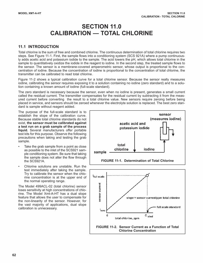
62
MODEL XMT-A-HT SECTION 11.0
CALIBRATION - TOTAL CHLORINE
SECTION 11.0CALIBRATION — TOTAL CHLORINE
11.1 INTRODUCTION
Total chlorine is the sum of free and combined chlorine. The continuous determination of total chlorine requires twosteps. See Figure 11-1. First, the sample flows into a conditioning system (SCS 921A) where a pump continuous-ly adds acetic acid and potassium iodide to the sample. The acid lowers the pH, which allows total chlorine in thesample to quantitatively oxidize the iodide in the reagent to iodine. In the second step, the treated sample flows tothe sensor. The sensor is a membrane-covered amperometric sensor, whose output is proportional to the con-centration of iodine. Because the concentration of iodine is proportional to the concentration of total chlorine, thetransmitter can be calibrated to read total chlorine.
Figure 11-2 shows a typical calibration curve for a total chlorine sensor. Because the sensor really measuresiodine, calibrating the sensor requires exposing it to a solution containing no iodine (zero standard) and to a solu-tion containing a known amount of iodine (full-scale standard).
The zero standard is necessary because the sensor, even when no iodine is present, generates a small currentcalled the residual current. The transmitter compensates for the residual current by subtracting it from the meas-ured current before converting the result to a total chlorine value. New sensors require zeroing before beingplaced in service, and sensors should be zeroed whenever the electrolyte solution is replaced. The best zero stan-dard is sample without reagent added.
The purpose of the full-scale standard is toestablish the slope of the calibration curve.Because stable total chlorine standards do notexist, the sensor must be calibrated againsta test run on a grab sample of the processliquid. Several manufacturers offer portabletest kits for this purpose. Observe the followingprecautions when taking and testing the grabsample.
• Take the grab sample from a point as closeas possible to the inlet of the SCS921 sam-ple conditioning system. Be sure that takingthe sample does not alter the flow throughthe SCS921A.
• Chlorine solutions are unstable. Run thetest immediately after taking the sample.Try to calibrate the sensor when the chlo-rine concentration is at the upper end ofthe normal operating range.
The Model 499ACL-02 (total chlorine) sensorloses sensitivity at high concentrations of chlo-rine. The Model Xmt-A-HT has a dual slopefeature that allows the user to compensate forthe non-linearity of the sensor. However, forthe vast majority of applications, dual slopecalibration is unnecessary.
FIGURE 11-1. Determination of Total Chlorine
FIGURE 11-2. Sensor Current as a Function of TotalChlorine Concentration

63
MODEL XMT-A-HT SECTION 11.0
CALIBRATION - TOTAL CHLORINE
11.2 PROCEDURE — ZEROING THE SENSOR
1. Complete the startup sequence described in the SCS921 instruction manual.
2. Remove the reagent uptake tube from the reagent bottle and let it dangle in air. The peristaltic pump will sim-
ply pump air into the sample.
3. Let the system run until the sensor current is stable. The sensor current will drop rapidly at first and then grad-
ually reach a stable zero value. To monitor the sensor current, go to the main display and press ê until the
input current screen appears. Note the units: nA is nanoamps, µA is microamps. Typical zero current for a free
chlorine sensor is between -10 and +30 nA.
A new sensor or a sensor in which the electrolyte solution has been replaced may require several hours (oc-
casionally as long as overnight) to reach a minimum current. DO NOT START THE ZERO ROUTINE UNTIL
THE SENSOR HAS BEEN IN ZERO SOLUTION FOR AT LEAST TWO HOURS.
4. Press MENU. The menu screen appears. Choose Calibrate.
5. Choose Chlorine.
6. Choose Zero.
7. The screen at left appears. The top line is the raw sensor current.
8. Once the reading is stable, the screen at left appears. Sensor zero iscomplete and the transmitter has stored the zero current. The screenremains until the operator presses MENU then EXIT to return to themain display.
NOTE
Pressing ENTER during the zero step will cause the transmitter touse the present sensor current as the zero current. If the sensor iszeroed before the current has reach a minimum stable value, sub-sequent readings will be in error.
9. This screen appears if the zero current is extremely high. See Section17 for troubleshooting. To repeat the zero step, press EXIT and chooseZero.
10. This screen appears if the zero current is moderately high. To continue,choose Yes. To repeat the zero step, choose No. See Section 15 fortroubleshooting.
Cal?
Chlorine Temp
Cal?
InProcess Zero
Live 200nA
Zeroing Wait
Sensor Zero Fail
Current too high
Possible ZeroErr
Proceed? Yes No
Calibrate Hold
Program Display
Live 0.000ppm
Sensor Zero Done
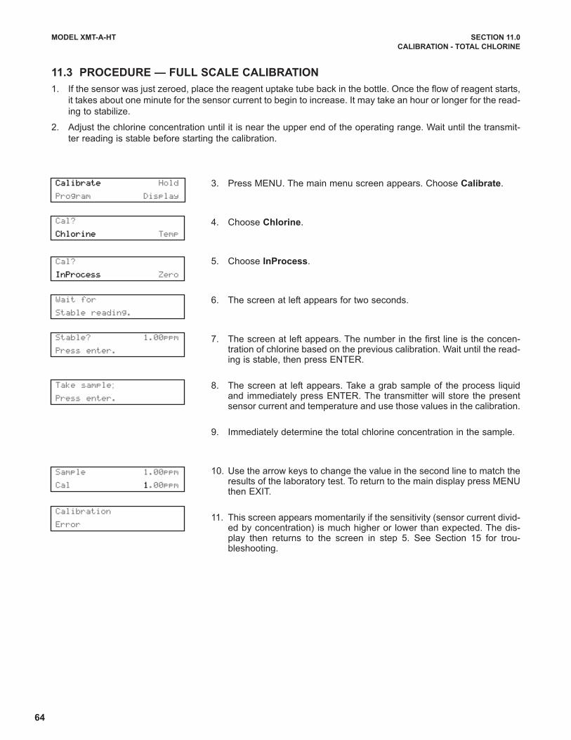
64
MODEL XMT-A-HT SECTION 11.0
CALIBRATION - TOTAL CHLORINE
11.3 PROCEDURE — FULL SCALE CALIBRATION
1. If the sensor was just zeroed, place the reagent uptake tube back in the bottle. Once the flow of reagent starts,
it takes about one minute for the sensor current to begin to increase. It may take an hour or longer for the read-
ing to stabilize.
2. Adjust the chlorine concentration until it is near the upper end of the operating range. Wait until the transmit-
ter reading is stable before starting the calibration.
3. Press MENU. The main menu screen appears. Choose Calibrate.
4. Choose Chlorine.
5. Choose InProcess.
6. The screen at left appears for two seconds.
7. The screen at left appears. The number in the first line is the concen-tration of chlorine based on the previous calibration. Wait until the read-ing is stable, then press ENTER.
8. The screen at left appears. Take a grab sample of the process liquidand immediately press ENTER. The transmitter will store the presentsensor current and temperature and use those values in the calibration.
9. Immediately determine the total chlorine concentration in the sample.
10. Use the arrow keys to change the value in the second line to match theresults of the laboratory test. To return to the main display press MENUthen EXIT.
11. This screen appears momentarily if the sensitivity (sensor current divid-ed by concentration) is much higher or lower than expected. The dis-play then returns to the screen in step 5. See Section 15 for trou-bleshooting.
Cal?
Chlorine Temp
Calibrate Hold
Program Display
Cal?
InProcess Zero
Wait for
Stable reading.
Stable? 1.00ppm
Press enter.
Take sample;
Press enter.
Sample 1.00ppm
Cal 1.00ppm
Calibration
Error

65
MODEL XMT-A-HT SECTION 11.0
CALIBRATION - TOTAL CHLORINE
11.4 DUAL SLOPE CALIBRATION
Figure 11-3 shows the principle of dual slope calibration. Between zero and concentration C1, the sensor re-
sponse is linear. When the concentration of chlorine becomes greater than C1, the response is non-linear. In spite
of the non-linearity, the sensor response between C1 and C2 can be approximated by a straight line.
Dual slope calibration is rarely needed. It is probably useful in fewer than 5% of applications.
1. Be sure the transmitter has been configured for dual slope
calibration. See Section 7.4.
2. Place the sensor in the zero solution. (see Section 10.1).
Be sure no air bubbles are trapped against the membrane.
The sensor current will drop rapidly at first and then grad-
ually reach a stable zero value. To monitor the sensor cur-
rent, go to the main display and press ê until the input cur-
rent screen appears. Note the units: nA is nanoamps, µA
is microamps. Typical zero current for a total chlorine sen-
sor is between -10 and +30 nA.
A new sensor or a sensor in which the electrolyte solution
has been replaced may require several hours (occasional-
ly as long as overnight) to reach a minimum current. DO
NOT START THE ZERO ROUTINE UNTIL THE SENSOR
HAS BEEN IN ZERO SOLUTION FOR AT LEAST TWO
HOURS.
3. Press MENU. The main menu screen appears. Choose Calibrate.
4. Choose Chlorine.
5. Choose Zero.
6. The screen at left appears. The top line is the raw sensor current.
7. Once the reading is stable, the screen at left appears. Sensor zero iscomplete and the transmitter has stored the zero current. The displayreturns to the screen in step 6.
NOTE
Pressing ENTER during the zero step will cause the transmitter touse the present sensor current as the zero current. If the sensor iszeroed before the current has reach a minimum stable value, sub-sequent readings will be in error.
8. This screen appears if the zero current is extremely high. See Section15 for troubleshooting. To repeat the zero step, press EXIT and chooseZero.
Process continued on following page.
FIGURE 11-3. Dual Slope Calibration
Cal?
Chlorine Temp
Cal?
Zero pt1 pt2
Live 200nA
Zeroing Wait
Sensor Zero Fail
Current too high
Calibrate Hold
Program Display
Live 0.000ppm
Sensor Zero Done
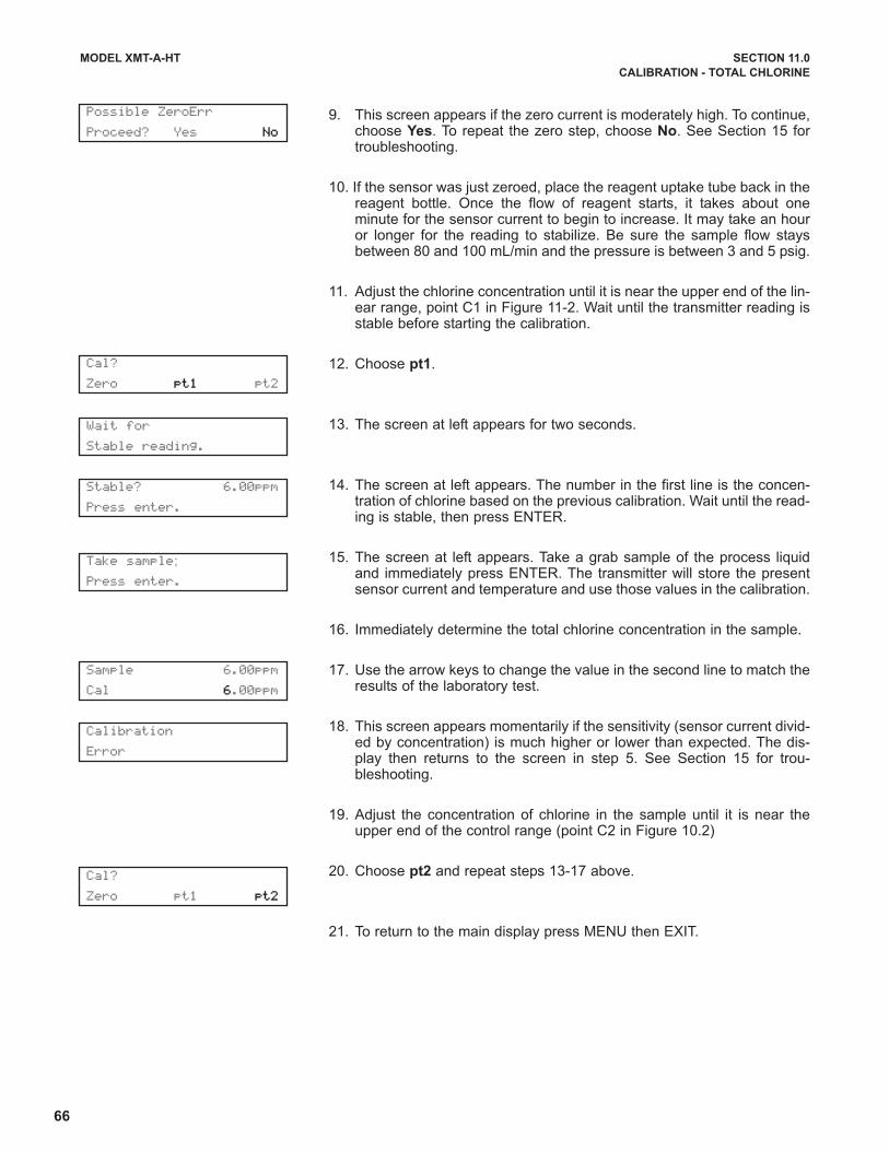
66
MODEL XMT-A-HT SECTION 11.0
CALIBRATION - TOTAL CHLORINE
9. This screen appears if the zero current is moderately high. To continue,choose Yes. To repeat the zero step, choose No. See Section 15 fortroubleshooting.
10. If the sensor was just zeroed, place the reagent uptake tube back in thereagent bottle. Once the flow of reagent starts, it takes about oneminute for the sensor current to begin to increase. It may take an houror longer for the reading to stabilize. Be sure the sample flow staysbetween 80 and 100 mL/min and the pressure is between 3 and 5 psig.
11. Adjust the chlorine concentration until it is near the upper end of the lin-ear range, point C1 in Figure 11-2. Wait until the transmitter reading isstable before starting the calibration.
12. Choose pt1.
13. The screen at left appears for two seconds.
14. The screen at left appears. The number in the first line is the concen-tration of chlorine based on the previous calibration. Wait until the read-ing is stable, then press ENTER.
15. The screen at left appears. Take a grab sample of the process liquidand immediately press ENTER. The transmitter will store the presentsensor current and temperature and use those values in the calibration.
16. Immediately determine the total chlorine concentration in the sample.
17. Use the arrow keys to change the value in the second line to match theresults of the laboratory test.
18. This screen appears momentarily if the sensitivity (sensor current divid-ed by concentration) is much higher or lower than expected. The dis-play then returns to the screen in step 5. See Section 15 for trou-bleshooting.
19. Adjust the concentration of chlorine in the sample until it is near theupper end of the control range (point C2 in Figure 10.2)
20. Choose pt2 and repeat steps 13-17 above.
21. To return to the main display press MENU then EXIT.
Possible ZeroErr
Proceed? Yes No
Cal?
Zero pt1 pt2
Cal?
Zero pt1 pt2
Wait for
Stable reading.
Stable? 6.00ppm
Press enter.
Take sample;
Press enter.
Sample 6.00ppm
Cal 6.00ppm
Calibration
Error
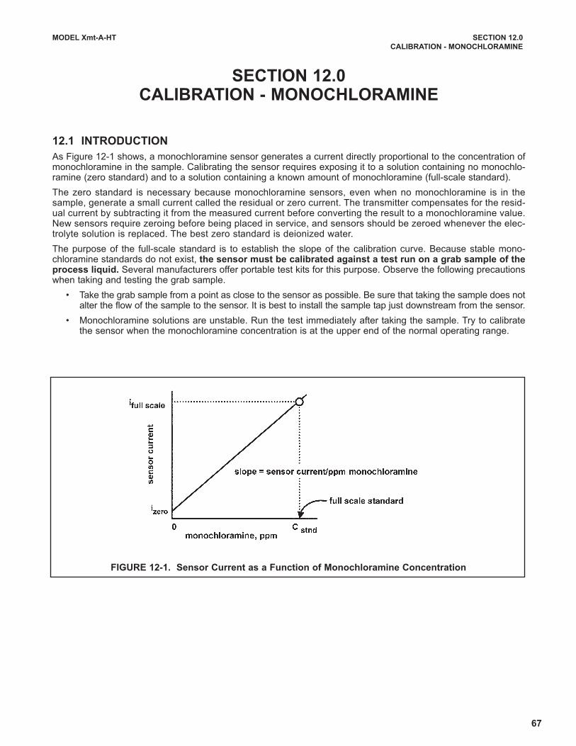
67
MODEL Xmt-A-HT SECTION 12.0
CALIBRATION - MONOCHLORAMINE
SECTION 12.0CALIBRATION - MONOCHLORAMINE
12.1 INTRODUCTION
As Figure 12-1 shows, a monochloramine sensor generates a current directly proportional to the concentration ofmonochloramine in the sample. Calibrating the sensor requires exposing it to a solution containing no monochlo-ramine (zero standard) and to a solution containing a known amount of monochloramine (full-scale standard).
The zero standard is necessary because monochloramine sensors, even when no monochloramine is in thesample, generate a small current called the residual or zero current. The transmitter compensates for the resid-ual current by subtracting it from the measured current before converting the result to a monochloramine value.New sensors require zeroing before being placed in service, and sensors should be zeroed whenever the elec-trolyte solution is replaced. The best zero standard is deionized water.
The purpose of the full-scale standard is to establish the slope of the calibration curve. Because stable mono-chloramine standards do not exist, the sensor must be calibrated against a test run on a grab sample of theprocess liquid. Several manufacturers offer portable test kits for this purpose. Observe the following precautionswhen taking and testing the grab sample.
• Take the grab sample from a point as close to the sensor as possible. Be sure that taking the sample does notalter the flow of the sample to the sensor. It is best to install the sample tap just downstream from the sensor.
• Monochloramine solutions are unstable. Run the test immediately after taking the sample. Try to calibratethe sensor when the monochloramine concentration is at the upper end of the normal operating range.
FIGURE 12-1. Sensor Current as a Function of Monochloramine Concentration
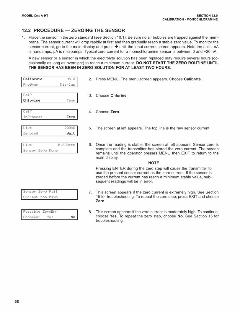
68
MODEL Xmt-A-HT SECTION 12.0
CALIBRATION - MONOCHLORAMINE
12.2 PROCEDURE — ZEROING THE SENSOR
1. Place the sensor in the zero standard (see Section 10.1). Be sure no air bubbles are trapped against the mem-
brane. The sensor current will drop rapidly at first and then gradually reach a stable zero value. To monitor the
sensor current, go to the main display and press ê until the input current screen appears. Note the units: nA
is nanoamps, µA is microamps. Typical zero current for a monochloramine sensor is between 0 and +20 nA.
A new sensor or a sensor in which the electrolyte solution has been replaced may require several hours (oc-
casionally as long as overnight) to reach a minimum current. DO NOT START THE ZERO ROUTINE UNTIL
THE SENSOR HAS BEEN IN ZERO SOLUTION FOR AT LEAST TWO HOURS.
2. Press MENU. The menu screen appears. Choose Calibrate.
3. Choose Chlorine.
4. Choose Zero.
5. The screen at left appears. The top line is the raw sensor current.
6. Once the reading is stable, the screen at left appears. Sensor zero iscomplete and the transmitter has stored the zero current. The screenremains until the operator presses MENU then EXIT to return to themain display.
NOTE
Pressing ENTER during the zero step will cause the transmitter touse the present sensor current as the zero current. If the sensor iszeroed before the current has reach a minimum stable value, sub-sequent readings will be in error.
7. This screen appears if the zero current is extremely high. See Section15 for troubleshooting. To repeat the zero step, press EXIT and chooseZero.
8. This screen appears if the zero current is moderately high. To continue,choose Yes. To repeat the zero step, choose No. See Section 15 fortroubleshooting.
Cal?
Chlorine Temp
Cal?
InProcess Zero
Live 200nA
Zeroing Wait
Sensor Zero Fail
Current too high
Possible ZeroErr
Proceed? Yes No
Calibrate Hold
Program Display
Live 0.000ppm
Sensor Zero Done
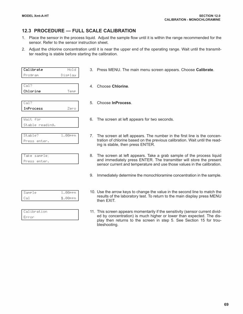
69
MODEL Xmt-A-HT SECTION 12.0
CALIBRATION - MONOCHLORAMINE
12.3 PROCEDURE — FULL SCALE CALIBRATION
1. Place the sensor in the process liquid. Adjust the sample flow until it is within the range recommended for the
sensor. Refer to the sensor instruction sheet.
2. Adjust the chlorine concentration until it is near the upper end of the operating range. Wait until the transmit-
ter reading is stable before starting the calibration.
3. Press MENU. The main menu screen appears. Choose Calibrate.
4. Choose Chlorine.
5. Choose InProcess.
6. The screen at left appears for two seconds.
7. The screen at left appears. The number in the first line is the concen-tration of chlorine based on the previous calibration. Wait until the read-ing is stable, then press ENTER.
8. The screen at left appears. Take a grab sample of the process liquidand immediately press ENTER. The transmitter will store the presentsensor current and temperature and use those values in the calibration.
9. Immediately determine the monochloramine concentration in the sample.
10. Use the arrow keys to change the value in the second line to match theresults of the laboratory test. To return to the main display press MENUthen EXIT.
11. This screen appears momentarily if the sensitivity (sensor current divid-ed by concentration) is much higher or lower than expected. The dis-play then returns to the screen in step 5. See Section 15 for trou-bleshooting.
Cal?
Chlorine Temp
Calibrate Hold
Program Display
Cal?
InProcess Zero
Wait for
Stable reading.
Stable? 1.00ppm
Press enter.
Take sample;
Press enter.
Sample 1.00ppm
Cal 1.00ppm
Calibration
Error

70
MODEL XMT-A-HT SECTION 13.0
CALIBRATION - OZONE
SECTION 13.0CALIBRATION — OZONE
13.1 INTRODUCTION
As Figure 13-1 shows, an ozone sensor generates a current directly proportional to the concentration of ozone inthe sample. Calibrating the sensor requires exposing it to a solution containing no ozone (zero standard) and to asolution containing a known amount of ozone (full-scale standard).
The zero standard is necessary because ozone sensors, even when no ozone is in the sample, generate a smallcurrent called the residual or zero current. The transmitter compensates for the residual current by subtracting itfrom the measured current before converting the result to an ozone value. New sensors require zeroing beforebeing placed in service, and sensors should be zeroed whenever the electrolyte solution is replaced. The best zerostandard is deionized water.
The purpose of the full-scale standard is to establish the slope of the calibration curve. Because stable ozone stan-dards do not exist, the sensor must be calibrated against a test run on a grab sample of the process liquid.Several manufacturers offer portable test kits for this purpose. Observe the following precautions when taking andtesting the grab sample.
• Take the grab sample from a point as close to the sensor as possible. Be sure that taking the sample does notalter the flow of the sample to the sensor. It is best to install the sample tap just downstream from the sensor.
• Ozone solutions are unstable. Run the test immediately after taking the sample. Try to calibrate the sensorwhen the ozone concentration is at the upper end of the normal operating range.
FIGURE 13-1. Sensor Current as a Function of Ozone Concentration
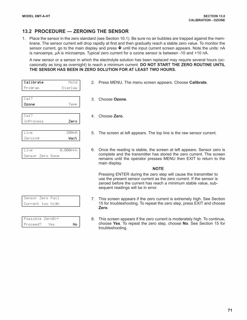
71
MODEL XMT-A-HT SECTION 13.0
CALIBRATION - OZONE
13.2 PROCEDURE — ZEROING THE SENSOR
1. Place the sensor in the zero standard (see Section 10.1). Be sure no air bubbles are trapped against the mem-
brane. The sensor current will drop rapidly at first and then gradually reach a stable zero value. To monitor the
sensor current, go to the main display and press ê until the input current screen appears. Note the units: nA
is nanoamps, µA is microamps. Typical zero current for a ozone sensor is between -10 and +10 nA.
A new sensor or a sensor in which the electrolyte solution has been replaced may require several hours (oc-
casionally as long as overnight) to reach a minimum current. DO NOT START THE ZERO ROUTINE UNTIL
THE SENSOR HAS BEEN IN ZERO SOLUTION FOR AT LEAST TWO HOURS.
2. Press MENU. The menu screen appears. Choose Calibrate.
3. Choose Ozone.
4. Choose Zero.
5. The screen at left appears. The top line is the raw sensor current.
6. Once the reading is stable, the screen at left appears. Sensor zero iscomplete and the transmitter has stored the zero current. The screenremains until the operator presses MENU then EXIT to return to themain display.
NOTE
Pressing ENTER during the zero step will cause the transmitter touse the present sensor current as the zero current. If the sensor iszeroed before the current has reach a minimum stable value, sub-sequent readings will be in error.
7. This screen appears if the zero current is extremely high. See Section15 for troubleshooting. To repeat the zero step, press EXIT and chooseZero.
8. This screen appears if the zero current is moderately high. To continue,choose Yes. To repeat the zero step, choose No. See Section 15 fortroubleshooting.
Cal?
Ozone Temp
Cal?
InProcess Zero
Live 200nA
Zeroing Wait
Sensor Zero Fail
Current too high
Possible ZeroErr
Proceed? Yes No
Calibrate Hold
Program Display
Live 0.000ppm
Sensor Zero Done

72
MODEL XMT-A-HT SECTION 13.0
CALIBRATION - OZONE
13.3 PROCEDURE — FULL SCALE CALIBRATION
1. Place the sensor in the process liquid. Adjust the sample flow until it is within the range recommended for the
sensor. Refer to the sensor instruction sheet.
2. Adjust the ozone concentration until it is near the upper end of the operating range. Wait until the transmitter
reading is stable before starting the calibration.
3. Press MENU. The main menu screen appears. Choose Calibrate.
4. Choose Ozone.
5. Choose InProcess.
6. The screen at left appears for two seconds.
7. The screen at left appears. The number in the first line is the concen-tration of chlorine based on the previous calibration. Wait until the read-ing is stable, then press ENTER.
8. The screen at left appears. Take a grab sample of the process liquidand immediately press ENTER. The transmitter will store the presentsensor current and temperature and use those values in the calibration.
9. Immediately determine the ozone concentration in the sample.
10. Use the arrow keys to change the value in the second line to match theresults of the laboratory test. To return to the main display press MENUthen EXIT.
11. This screen appears momentarily if the sensitivity (sensor current divid-ed by concentration) is much higher or lower than expected. The dis-play then returns to the screen in step 5. See Section 15 for trou-bleshooting.
Cal?
Ozone Temp
Calibrate Hold
Program Display
Cal?
InProcess Zero
Wait for
Stable reading.
Stable? 1.00ppm
Press enter.
Take sample;
Press enter.
Sample 1.00ppm
Cal 1.00ppm
Calibration
Error
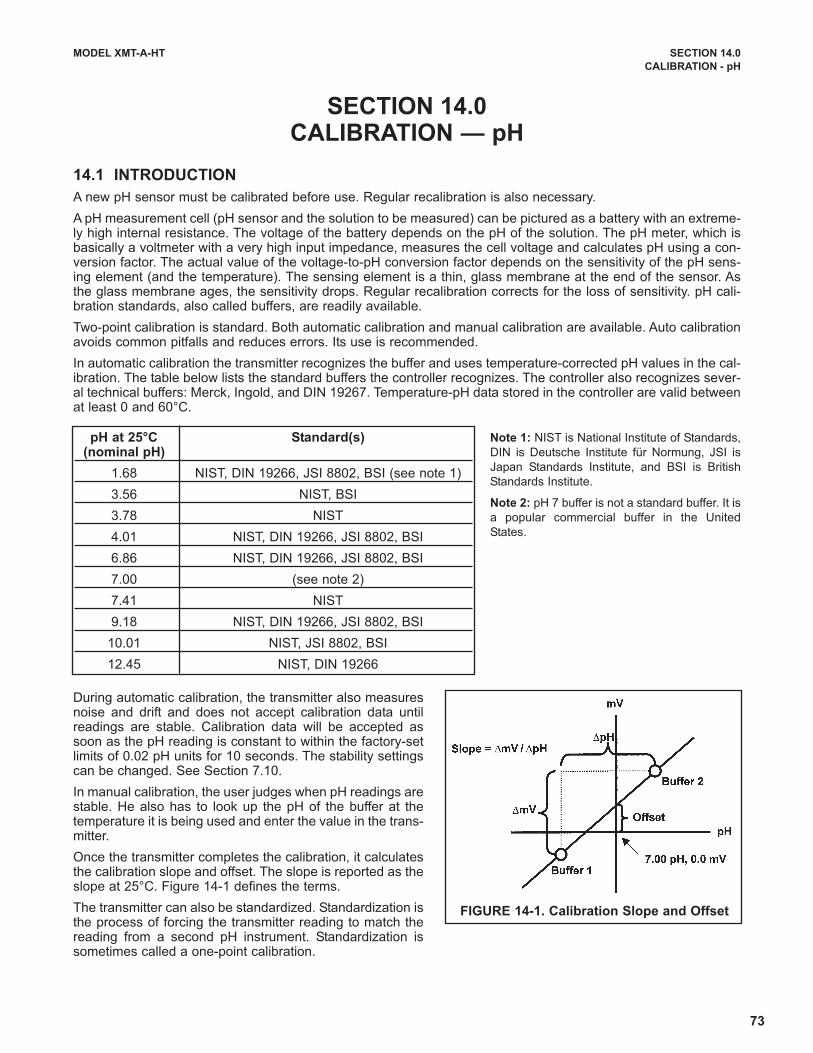
73
MODEL XMT-A-HT SECTION 14.0
CALIBRATION - pH
SECTION 14.0CALIBRATION — pH
14.1 INTRODUCTION
A new pH sensor must be calibrated before use. Regular recalibration is also necessary.
A pH measurement cell (pH sensor and the solution to be measured) can be pictured as a battery with an extreme-ly high internal resistance. The voltage of the battery depends on the pH of the solution. The pH meter, which isbasically a voltmeter with a very high input impedance, measures the cell voltage and calculates pH using a con-version factor. The actual value of the voltage-to-pH conversion factor depends on the sensitivity of the pH sens-ing element (and the temperature). The sensing element is a thin, glass membrane at the end of the sensor. Asthe glass membrane ages, the sensitivity drops. Regular recalibration corrects for the loss of sensitivity. pH cali-bration standards, also called buffers, are readily available.
Two-point calibration is standard. Both automatic calibration and manual calibration are available. Auto calibrationavoids common pitfalls and reduces errors. Its use is recommended.
In automatic calibration the transmitter recognizes the buffer and uses temperature-corrected pH values in the cal-ibration. The table below lists the standard buffers the controller recognizes. The controller also recognizes sever-al technical buffers: Merck, Ingold, and DIN 19267. Temperature-pH data stored in the controller are valid betweenat least 0 and 60°C.
pH at 25°C Standard(s)(nominal pH)
1.68 NIST, DIN 19266, JSI 8802, BSI (see note 1)
3.56 NIST, BSI
3.78 NIST
4.01 NIST, DIN 19266, JSI 8802, BSI
6.86 NIST, DIN 19266, JSI 8802, BSI
7.00 (see note 2)
7.41 NIST
9.18 NIST, DIN 19266, JSI 8802, BSI
10.01 NIST, JSI 8802, BSI
12.45 NIST, DIN 19266
FIGURE 14-1. Calibration Slope and Offset
Note 1: NIST is National Institute of Standards,
DIN is Deutsche Institute für Normung, JSI is
Japan Standards Institute, and BSI is British
Standards Institute.
Note 2: pH 7 buffer is not a standard buffer. It is
a popular commercial buffer in the United
States.
During automatic calibration, the transmitter also measuresnoise and drift and does not accept calibration data untilreadings are stable. Calibration data will be accepted assoon as the pH reading is constant to within the factory-setlimits of 0.02 pH units for 10 seconds. The stability settingscan be changed. See Section 7.10.
In manual calibration, the user judges when pH readings arestable. He also has to look up the pH of the buffer at thetemperature it is being used and enter the value in the trans-mitter.
Once the transmitter completes the calibration, it calculatesthe calibration slope and offset. The slope is reported as theslope at 25°C. Figure 14-1 defines the terms.
The transmitter can also be standardized. Standardization isthe process of forcing the transmitter reading to match thereading from a second pH instrument. Standardization issometimes called a one-point calibration.
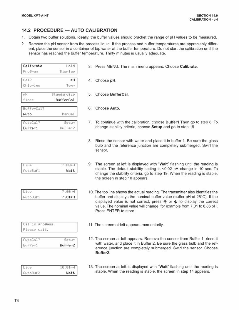
74
MODEL XMT-A-HT SECTION 14.0
CALIBRATION - pH
14.2 PROCEDURE — AUTO CALIBRATION
1. Obtain two buffer solutions. Ideally, the buffer values should bracket the range of pH values to be measured.
2. Remove the pH sensor from the process liquid. If the process and buffer temperatures are appreciably differ-
ent, place the sensor in a container of tap water at the buffer temperature. Do not start the calibration until the
sensor has reached the buffer temperature. Thirty minutes is usually adequate.
3. Press MENU. The main menu appears. Choose Calibrate.
4. Choose pH.
5. Choose BufferCal.
6. Choose Auto.
7. To continue with the calibration, choose Buffer1.Then go to step 8. To
change stability criteria, choose Setup and go to step 19.
8. Rinse the sensor with water and place it in buffer 1. Be sure the glass
bulb and the reference junction are completely submerged. Swirl the
sensor.
9. The screen at left is displayed with “Wait” flashing until the reading is
stable. The default stability setting is <0.02 pH change in 10 sec. To
change the stability criteria, go to step 19. When the reading is stable,
the screen in step 10 appears.
10. The top line shows the actual reading. The transmitter also identifies the
buffer and displays the nominal buffer value (buffer pH at 25°C). If the
displayed value is not correct, press é or ê to display the correct
value. The nominal value will change, for example from 7.01 to 6.86 pH.
Press ENTER to store.
11. The screen at left appears momentarily.
12. The screen at left appears. Remove the sensor from Buffer 1, rinse it
with water, and place it in Buffer 2. Be sure the glass bulb and the ref-
erence junction are completely submerged. Swirl the sensor. Choose
Buffer2.
13. The screen at left is displayed with “Wait” flashing until the reading is
stable. When the reading is stable, the screen in step 14 appears.
Calibrate Hold
Program Display
Cal? pH
Chlorine Temp
BufferCal?
Auto Manual
AutoCal? Setup
Buffer1 Buffer2
AutoCal? Setup
Buffer1 Buffer2
pH Standardize
Slope BufferCal
Live 7.00pH
AutoBuf1 Wait
Live 7.00pH
AutoBuf1 7.01pH
Live 10.01pH
AutoBuf2 Wait
Cal in progess.
Please wait.

75
MODEL XMT-A-HT SECTION 14.0
CALIBRATION - pH
14. The top line shows the actual reading. The transmitter also identifies the
buffer and displays the nominal buffer value (buffer pH at 25°C). If the
displayed value is not correct, press é or ê to display the correct
value. The nominal value will change, for example from 7.01 to 6.86 pH.
Press ENTER to store.
15. The screen at left appears momentarily.
16. If the calibration was successful, the transmitter will display the offset
and slope (at 25°). The display will return to the screen in step 6.
17. If the slope is out of range (less than 45 mV/pH or greater than 60
mV/pH) or if the offset exceeds the value programmed in Section 7.4, an
error screen appears. The display then returns to the screen in step 6.
18. To return to the main display, press MENU then EXIT.
19. Choosing Setup in step 7 causes the Buffer Stabilize screen to appear.
The transmitter will not accept calibration data until the pH reading is
stable. The default requirement is a pH change less than 0.02 units in
10 seconds. To change the stability criteria:
a. Enter the desired stabilization time
b. Enter the minimum amount the reading is permitted to change in
the time specified in step 19a.
20. To return to the main display, press MENU then EXIT.
Live 10.01pH
AutoBuf2 10.01pH
Buffer Stabilize
Time: 10sec
Restart time if
change > 0.02pH
Offset 0mV
Slope 59.16@25°C
Calibration
Error
Cal in progess.
Please wait.
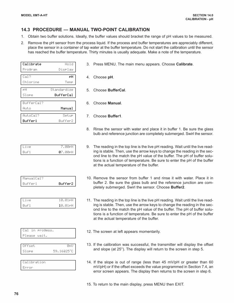
76
MODEL XMT-A-HT SECTION 14.0
CALIBRATION - pH
14.3 PROCEDURE — MANUAL TWO-POINT CALIBRATION
1. Obtain two buffer solutions. Ideally, the buffer values should bracket the range of pH values to be measured.
2. Remove the pH sensor from the process liquid. If the process and buffer temperatures are appreciably different,
place the sensor in a container of tap water at the buffer temperature. Do not start the calibration until the sensor
has reached the buffer temperature. Thirty minutes is usually adequate. Make a note of the temperature.
3. Press MENU. The main menu appears. Choose Calibrate.
4. Choose pH.
5. Choose BufferCal.
6. Choose Manual.
7. Choose Buffer1.
8. Rinse the sensor with water and place it in buffer 1. Be sure the glass
bulb and reference junction are completely submerged. Swirl the sensor.
9. The reading in the top line is the live pH reading. Wait until the live read-
ing is stable. Then, use the arrow keys to change the reading in the sec-
ond line to the match the pH value of the buffer. The pH of buffer solu-
tions is a function of temperature. Be sure to enter the pH of the buffer
at the actual temperature of the buffer.
10. Remove the sensor from buffer 1 and rinse it with water. Place it in
buffer 2. Be sure the glass bulb and the reference junction are com-
pletely submerged. Swirl the sensor. Choose Buffer2.
11. The reading in the top line is the live pH reading. Wait until the live read-
ing is stable. Then, use the arrow keys to change the reading in the sec-
ond line to the match the pH value of the buffer. The pH of buffer solu-
tions is a function of temperature. Be sure to enter the pH of the buffer
at the actual temperature of the buffer.
12. The screen at left appears momentarily.
13. If the calibration was successful, the transmitter will display the offset
and slope (at 25°). The display will return to the screen in step 5.
14. If the slope is out of range (less than 45 mV/pH or greater than 60
mV/pH) or if the offset exceeds the value programmed in Section 7.4, an
error screen appears. The display then returns to the screen in step 6.
15. To return to the main display, press MENU then EXIT.
Calibrate Hold
Program Display
Cal? pH
Chlorine Temp
BufferCal?
Auto Manual
AutoCal? Setup
Buffer1 Buffer2
ManualCal?
Buffer1 Buffer2
pH Standardize
Slope BufferCal
Live 7.00pH
Buf1 07.00pH
Live 10.01pH
Buf1 10.01pH
Cal in progess.
Please wait.
Offset 0mV
Slope 59.16@25°C
Calibration
Error

77
MODEL XMT-A-HT SECTION 14.0
CALIBRATION - pH
14.4 PROCEDURE — STANDARDIZATION
1. The pH measured by the transmitter can be changed to match the reading from a second or referee instru-
ment. The process of making the two readings agree is called standardization.
2. During standardization, the difference between the two values is converted to the equivalent voltage. The volt-
age, called the reference offset, is added to all subsequent measured cell voltages before they are converted
to pH. If after standardization the sensor is placed in a buffer solution, the measured pH will differ from the
buffer pH by an amount equivalent to the standardization offset.
3. Install the pH sensor in the process liquid.
4. Once readings are stable, measure the pH of the liquid using a referee instrument.
5. Because the pH of the process liquid may change if the temperature changes, measure the pH of the grab
sample immediately after taking it.
6. For poorly buffered samples, it is best to determine the pH of a continuously flowing sample from a point as
close as possible to the sensor.
7. Press MENU. The main menu appears. Choose Calibrate.
8. Choose pH.
9. Choose Standardize.
10. The top line shows the present reading. Use the arrow keys to change
the pH reading in the second line to match the pH reading from the ref-
eree instrument.
11. The screen at left appears if the entered pH was greater than 14.00 or
if the mV offset calculated by the transmitter during standardization
exceeds the reference offset limit programmed into the transmitter. The
display then returns to step 10. Repeat the standardization. To change
the reference offset from the default value (60 mV), see section 7.4.
12. If the entry was accepted the display returns to step 9.
13. To return to the main display, press MENU then EXIT.
Calibrate Hold
Program Display
pH: Standardize
Slope BufferCal
Cal? pH
Chlorine Temp
Calibration
Error
Live 7.01pH
Cal 07.01pH
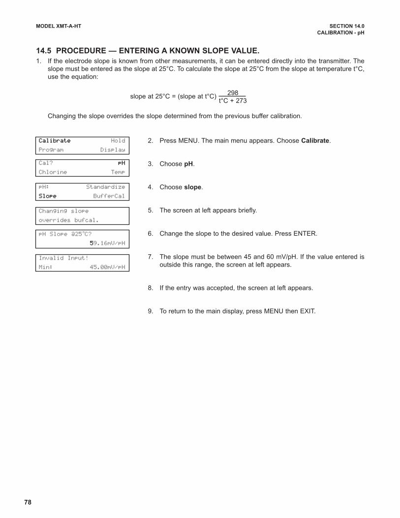
78
MODEL XMT-A-HT SECTION 14.0
CALIBRATION - pH
14.5 PROCEDURE — ENTERING A KNOWN SLOPE VALUE.
1. If the electrode slope is known from other measurements, it can be entered directly into the transmitter. The
slope must be entered as the slope at 25°C. To calculate the slope at 25°C from the slope at temperature t°C,
use the equation:
slope at 25°C = (slope at t°C)
Changing the slope overrides the slope determined from the previous buffer calibration.
2. Press MENU. The main menu appears. Choose Calibrate.
3. Choose pH.
4. Choose slope.
5. The screen at left appears briefly.
6. Change the slope to the desired value. Press ENTER.
7. The slope must be between 45 and 60 mV/pH. If the value entered is
outside this range, the screen at left appears.
8. If the entry was accepted, the screen at left appears.
9. To return to the main display, press MENU then EXIT.
298
t°C + 273
Invalid Input!
Min: 45.00mV/pH
Calibrate Hold
Program Display
Changing slope
overrides bufcal.
pH: Standardize
Slope BufferCal
pH Slope @25°C?
59.16mV/pH
Cal? pH
Chlorine Temp

79
MODEL Xmt-A-HT SECTION 15.0
TROUBLESHOOTING
SECTION 15.0TROUBLESHOOTING
15.1 OVERVIEW
The Xmt-A-HT transmitter continuously monitors itself and the sensor for problems. If the transmitter detects a
problem, the word "fault" or "warn" appears in the main display alternating with the measurement.
A fault condition means the measurement is seriously in error and is not to be trusted. A fault condition might also
mean that the transmitter has failed. Fault conditions must be corrected immediately. When a fault occurs the out-
put goes to 22.00 mA or the to value programmed in Section 7.3. The output can also be programmed to reflect
the live measurement.
A warning means that the instrument is usable, but steps should be taken as soon as possible to correct the con-
dition causing the warning.
See Section 15.2 for an explanation of fault and warning messages and suggested corrective actions.
The Xmt-A-HT also displays error and warning messages if a calibration is seriously in error. Refer to the section
below for assistance. Each section also contains hints for correcting other measurement and calibration problems.
For troubleshooting not related to measurement problems, see
Section 15.10.
Measurement Section
Temperature 15.3
Dissolved oxygen 15.4
Free chlorine 15.5
Total chlorine 15.6
Monochloramine 15.7
Ozone 15.8
pH 15.9
NOTE
A large number of information screens are available to aid troubleshooting. The most useful of these are
raw sensor current and sensitivity and zero current at last calibration. For pH measurements (available
with free chlorine only), sensor slope and offset and glass impedance are also available. To view the
information screens, go to the main display and press the ê key.
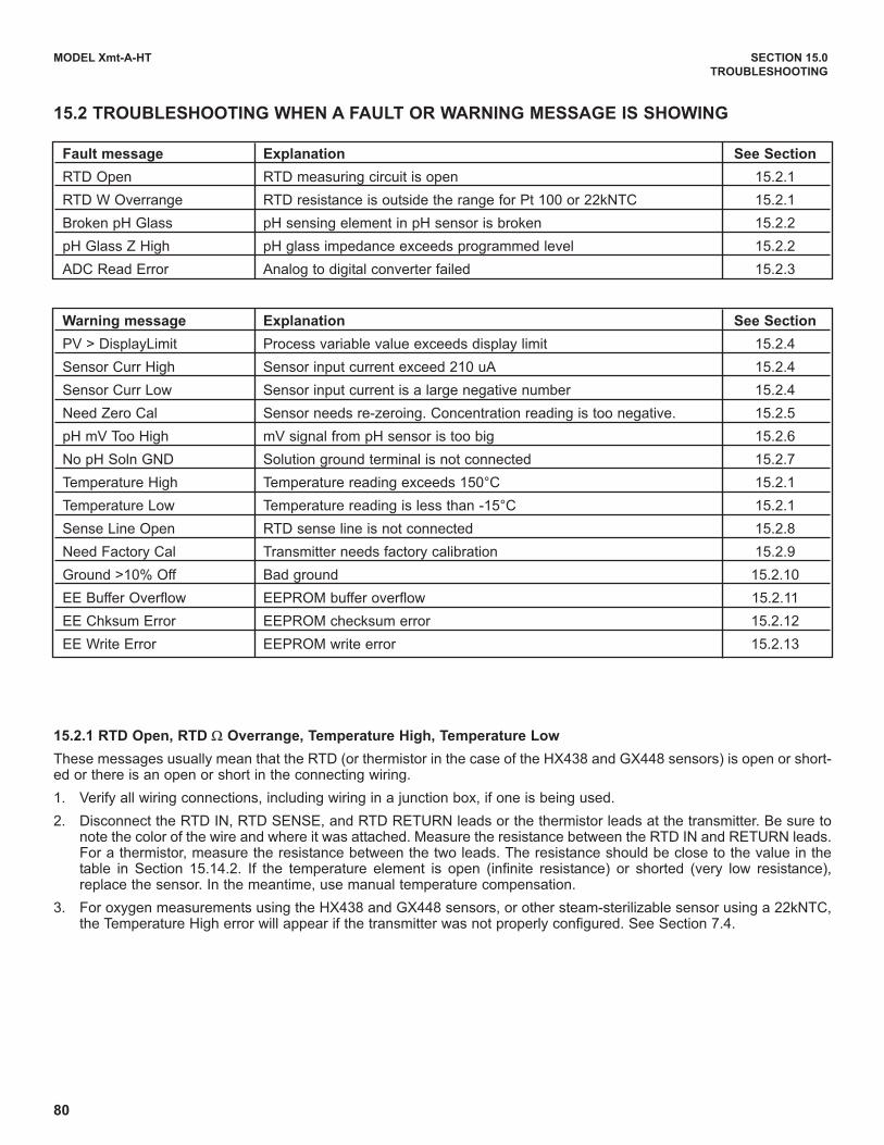
80
MODEL Xmt-A-HT SECTION 15.0
TROUBLESHOOTING
15.2 TROUBLESHOOTING WHEN A FAULT OR WARNING MESSAGE IS SHOWING
Fault message Explanation See Section
RTD Open RTD measuring circuit is open 15.2.1
RTD W Overrange RTD resistance is outside the range for Pt 100 or 22kNTC 15.2.1
Broken pH Glass pH sensing element in pH sensor is broken 15.2.2
pH Glass Z High pH glass impedance exceeds programmed level 15.2.2
ADC Read Error Analog to digital converter failed 15.2.3
Warning message Explanation See Section
PV > DisplayLimit Process variable value exceeds display limit 15.2.4
Sensor Curr High Sensor input current exceed 210 uA 15.2.4
Sensor Curr Low Sensor input current is a large negative number 15.2.4
Need Zero Cal Sensor needs re-zeroing. Concentration reading is too negative. 15.2.5
pH mV Too High mV signal from pH sensor is too big 15.2.6
No pH Soln GND Solution ground terminal is not connected 15.2.7
Temperature High Temperature reading exceeds 150°C 15.2.1
Temperature Low Temperature reading is less than -15°C 15.2.1
Sense Line Open RTD sense line is not connected 15.2.8
Need Factory Cal Transmitter needs factory calibration 15.2.9
Ground >10% Off Bad ground 15.2.10
EE Buffer Overflow EEPROM buffer overflow 15.2.11
EE Chksum Error EEPROM checksum error 15.2.12
EE Write Error EEPROM write error 15.2.13
15.2.1 RTD Open, RTD Ω Overrange, Temperature High, Temperature Low
These messages usually mean that the RTD (or thermistor in the case of the HX438 and GX448 sensors) is open or short-ed or there is an open or short in the connecting wiring.
1. Verify all wiring connections, including wiring in a junction box, if one is being used.
2. Disconnect the RTD IN, RTD SENSE, and RTD RETURN leads or the thermistor leads at the transmitter. Be sure tonote the color of the wire and where it was attached. Measure the resistance between the RTD IN and RETURN leads.For a thermistor, measure the resistance between the two leads. The resistance should be close to the value in thetable in Section 15.14.2. If the temperature element is open (infinite resistance) or shorted (very low resistance),replace the sensor. In the meantime, use manual temperature compensation.
3. For oxygen measurements using the HX438 and GX448 sensors, or other steam-sterilizable sensor using a 22kNTC,the Temperature High error will appear if the transmitter was not properly configured. See Section 7.4.

81
MODEL Xmt-A-HT SECTION 15.0
TROUBLESHOOTING
15.2.2 Broken pH Glass and pH Glass Z High
These messages mean that the pH sensor glass impedance is outside the programmed limits. To read the impedance goto the main display and press ê until Glass Imp appears in the display. The default lower limit is 10 MΩ. The default upperlimit is 1000 MΩ. Low glass impedance means the glass membrane — the sensing element in a pH sensor — is crackedor broken. High glass impedance means the membrane is aging and nearing the end of its useful life. High impedance canalso mean the pH sensor is not completely submerged in the process liquid.
1. Check the sensor wiring, including connections in a junction box.
2. Verify that the sensor is completely submerged in the process liquid.
3. Verify that the software switch identifying the position of the preamplifier is properly set. See Section 7.4.
4. Check the sensor response in buffers. If the sensor can be calibrated, it is in satisfactory condition. To disable the faultmessage, reprogram the glass impedance limits to include the measured impedance. If the sensor cannot be cali-brated, it has failed and must be replaced.
15.2.3 ADC Read Error
The analog to digital converter has probably failed.
1. Verify that sensor wiring is correct and connections are tight. Be sure to check connections at the junction box if oneis being used. See Section 3.1 for wiring information.
2. Disconnect the sensor(s) and simulate temperature and sensor input.
3. If the transmitter does not respond to simulate signals, call the factory for assistance.
15.2.4 PV>DisplayLimit, Sensor Curr High, Sensor Curr Low.
The first two messages imply that the amperometric sensor current is very high (greater than 210 µA) or the sensor cur-rent has a very large negative number. Normally, excessive current or negative current implies that the amperometric sen-sor is miswired or has failed. Occasionally, these messages may appear when a new sensor is first placed in service.
1. Verify that wiring is correct and connections are tight. Be sure to check connections at the junction box if one is beingused. Pay particular attention the anode and cathode connections.
2. Verify that the transmitter is configured for the correct measurement. See Section 7.4. Configuring the measurementssets (among other things) the polarizing voltage. Applying the wrong polarizing voltage to the sensor can cause a largenegative current.
3. If the sensor was just placed in service, put the sensor in the zero solution and observe the sensor current. It shouldbe moving fairly quickly toward zero. To view the sensor current go to the main display and press ê until Input Currentappears. Note the units: nA is nanoamps, µA is microamps.
4. Replace the sensor membrane and electrolyte solution and clean the cathode if necessary. See the sensor instructionsheet for details.
5. Replace the sensor.
To simulate See Section
Dissolved oxygen 15.11
Ozone, monochloramine, chlorine 15.12
pH 15.13
Temperature 15.14
82
MODEL Xmt-A-HT SECTION 15.0
TROUBLESHOOTING
15.2.5 Need Zero Cal
Need Zero Cal means the measured concentration is a large negative number. The transmitter subtracts the zero currentfrom the measured current before converting the result to a concentration reading. If the zero current is much greater thanthe measured current, the concentration reading will be negative.
1. Check the zero current and the present sensor current. To view the zero current, go to the main display and press êuntil Zero Current appears. The value shown is the zero current the last time the sensor was zeroed. To view the pres-ent sensor current, go to the main display and press ê until Input Current appears. Note the units: nA is nanoamps,µA is microamps.
2. Refer to the appropriate section for calibrating the sensor. Place the sensor in the zero solution. Verify that the sensorreading is within or at least very close to the zero current limits. It may take as long as overnight for the sensor to reacha stable zero current.
15.2.6 pH mV Too High
This message means the raw millivolt signal from the sensor is outside the range -2100 to 2100 mV.
1. Verify all wiring connections, including connections in a junction box.
2. Check that the pH sensor is completely submerged in the process liquid.
3. Check the pH sensor for cleanliness. If the sensor look fouled of dirty, clean it. Refer to the sensor instruction manualfor cleaning procedures.
15.2.7 No pH Soln GND
In the transmitter, the solution ground (Soln GND) terminal is connected to instrument common. Normally, unless the pHsensor has a solution ground, the reference terminal must be jumpered to the solution ground terminal. HOWEVER, WHENTHE pH SENSOR IS USED WITH A FREE CHLORINE SENSOR THIS CONNECTION IS NEVER MADE.
15.2.8 Sense Line Open
Most Rosemount Analytical sensors use a Pt100 or Pt1000 RTD in a three-wire configuration (see Figure 15-4). The in andreturn leads connect the RTD to the measuring circuit in the transmitter. A third wire, called the sense line, is connected tothe return lead. The sense line allows the transmitter to correct for the resistance of the in and return leads and to correctfor changes in lead wire resistance with changes in ambient temperature.
1. Verify that all wiring connections are secure, including connections in a junction box.
2. Disconnect the RTD SENSE and RTD RETURN wires. Measure the resistance between the leads. It should be lessthan 5Ω.
3. The transmitter can be operated with the sense line open. The measurement will be less accurate because the trans-mitter can no longer compensate for lead wire resistance. However, if the sensor is to be used at approximately con-stant ambient temperature, the lead wire resistance error can be eliminated by calibrating the sensor at the measure-ment temperature. Errors caused by changes in ambient temperature cannot be eliminated. To make the warning mes-sage disappear, connect the RTD SENSE and RETURN terminals with a jumper.
15.2.9 Need Factory Cal
This warning message means the transmitter requires factory calibration. Call the factory for assistance.
15.2.10 Ground >10% Off
This warning message means there is a problem with the analog circuitry. Call the factory for assistance.
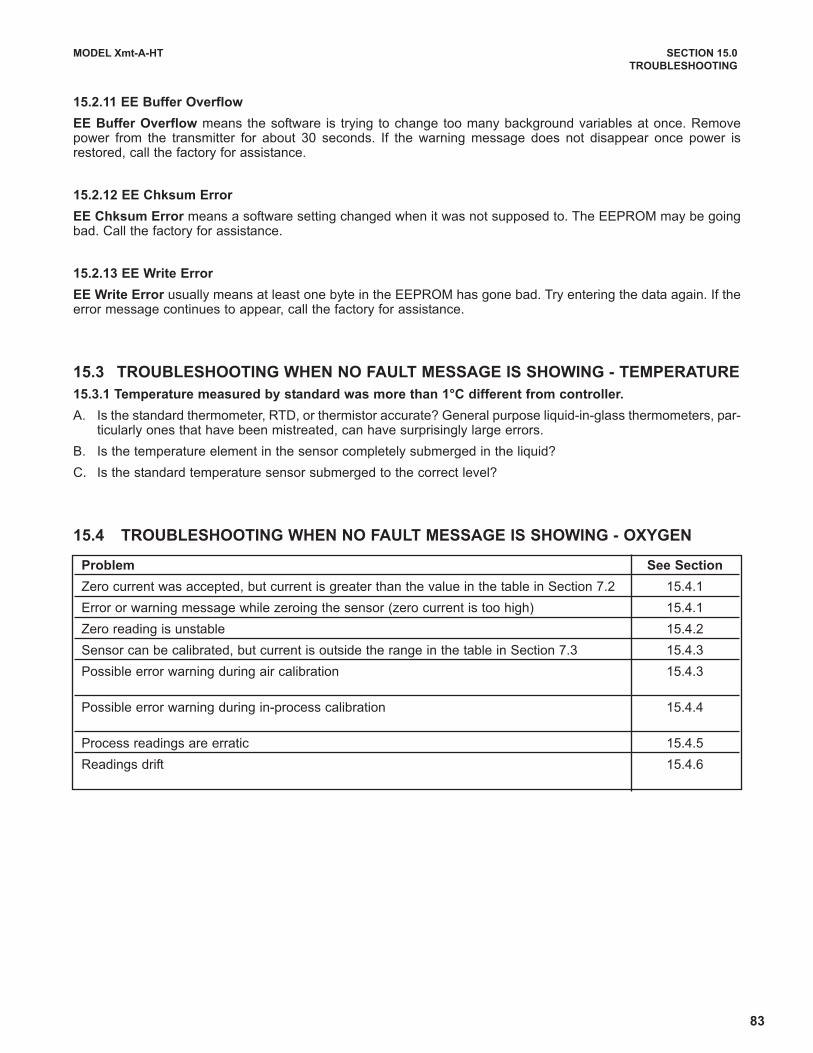
83
MODEL Xmt-A-HT SECTION 15.0
TROUBLESHOOTING
15.2.11 EE Buffer Overflow
EE Buffer Overflow means the software is trying to change too many background variables at once. Removepower from the transmitter for about 30 seconds. If the warning message does not disappear once power isrestored, call the factory for assistance.
15.2.12 EE Chksum Error
EE Chksum Error means a software setting changed when it was not supposed to. The EEPROM may be goingbad. Call the factory for assistance.
15.2.13 EE Write Error
EE Write Error usually means at least one byte in the EEPROM has gone bad. Try entering the data again. If theerror message continues to appear, call the factory for assistance.
15.3 TROUBLESHOOTING WHEN NO FAULT MESSAGE IS SHOWING - TEMPERATURE
15.3.1 Temperature measured by standard was more than 1°C different from controller.
A. Is the standard thermometer, RTD, or thermistor accurate? General purpose liquid-in-glass thermometers, par-ticularly ones that have been mistreated, can have surprisingly large errors.
B. Is the temperature element in the sensor completely submerged in the liquid?
C. Is the standard temperature sensor submerged to the correct level?
15.4 TROUBLESHOOTING WHEN NO FAULT MESSAGE IS SHOWING - OXYGEN
Problem See Section
Zero current was accepted, but current is greater than the value in the table in Section 7.2 15.4.1
Error or warning message while zeroing the sensor (zero current is too high) 15.4.1
Zero reading is unstable 15.4.2
Sensor can be calibrated, but current is outside the range in the table in Section 7.3 15.4.3
Possible error warning during air calibration 15.4.3
Possible error warning during in-process calibration 15.4.4
Process readings are erratic 15.4.5
Readings drift 15.4.6
84
MODEL Xmt-A-HT SECTION 15.0
TROUBLESHOOTING
15.4.1 Zero current is too high
A. Is the sensor properly wired to the analyzer? See Section 3.0.
B. Is the membrane completely covered with zero solution and are air bubbles not trapped against the mem-brane? Swirl and tap the sensor to release air bubbles.
C. Is the zero solution fresh and properly made? Zero the sensor in a solution of 5% sodium sulfite in water.Prepare the solution immediately before use. It has a shelf life of only a few days.
D. If the sensor is being zeroed with nitrogen gas, verify that the nitrogen is oxygen-free and the flow is adequateto prevent back-diffusion of air into the chamber.
E. The major contributor to the zero current is dissolved oxygen in the electrolyte solution inside the sensor. Along zeroing period usually means that an air bubble is trapped in the electrolyte. To ensure the 499ADO or499A TrDO sensor contains no air bubbles, carefully follow the procedure in the sensor manual for filling thesensor. If the electrolyte solution has just been replaced, allow several hours for the zero current to stabilize.On rare occasions, the sensor may require as long as overnight to zero.
F. Check the membrane for damage and replace the membrane if necessary
.
15.4.2 Zero reading Is unstable.
A. Is the sensor properly wired to the analyzer? See Section 3.0. Verify that all wiring connections are tight.
B. Readings are often erratic when a new or rebuilt sensor is first placed in service. Readings usually stabilizeafter an hour.
C. Is the space between the membrane and cathode filled with electrolyte solution and is the flow path betweenthe electrolyte reservoir and the membrane clear? Often the flow of electrolyte can be started by simply hold-ing the sensor with the membrane end pointing down and sharply shaking the sensor a few times as thoughshaking down a clinical thermometer. If shaking does not work, perform the checks below. Refer to the sensorinstruction manuals for additional information.
For 499ADO and 499A TrDO sensors, verify that the holes at the base of the cathode stem are open (use astraightened paperclip to clear the holes). Also verify that air bubbles are not blocking the holes. Fill the reservoirand establish electrolyte flow to the cathode. Refer to the sensor instruction manual for the detailed procedure.
For Gx438 and Hx438 sensors, the best way to ensure that there is an adequate supply of electrolyte solutionis to simply add fresh electrolyte solution to the sensor. Refer to the sensor instruction manual for details.
15.4.3 Sensor can be calibrated, but current in air is too high or too low
A. Is the sensor properly wired to the analyzer? See Section 3.0. Verify that all connections are tight.
B. Is the membrane dry? The membrane must be dry during air calibration. A droplet of water on the membraneduring air calibration will lower the sensor current and cause an inaccurate calibration.
C. If the sensor current in air is very low and the sensor is new, either the electrolyte flow has stopped or the mem-brane is torn or loose. For instructions on how to restart electrolyte flow see Section 15.4.2 or refer to the sen-sor instruction manual. To replace a torn membrane, refer to the sensor instruction manual.
D. Is the temperature low? Sensor current is a strong function of temperature. The sensor current decreasesabout 3% for every °C drop in temperature.
E. Is the membrane fouled or coated? A dirty membrane inhibits diffusion of oxygen through the membrane,reducing the sensor current. Clean the membrane by rinsing it with a stream of water from a wash bottle or bygently wiping the membrane with a soft tissue. If cleaning the membrane does not improve the sensorresponse, replace the membrane and electrolyte solution. If necessary, polish the cathode. See the sensorinstruction sheet for more information.
15.4.4 Possible error warning during in-process calibration
This error warning appears if the current process reading and the reading it is being changed to, ie, the readingfrom the standard instrument, are appreciably different.
A. Is the standard instrument properly zeroed and calibrated?
B. Are the standard and process sensor measuring the same sample? Place the sensors as close together aspossible.
C. Is the process sensor working properly? Check the response of the process sensor in air and in sodium sul-fite solution.
85
MODEL Xmt-A-HT SECTION 15.0
TROUBLESHOOTING
15.4.5 Process readings are erratic.
A. Readings are often erratic when a new sensor or a rebuilt sensor is first placed in service. The current usually sta-bilizes after a few hours.
B. Is the sample flow within the recommended range? High sample flow may cause erratic readings. Refer to the sen-sor instruction manual for recommended flow rates.
C. Gas bubbles impinging on the membrane may cause erratic readings. Orienting the sensor at an angle away fromvertical may reduce the noise.
D. The holes between the membrane and electrolyte reservoir might be plugged (applies to Models 499A DO and 499ATrDO sensors only). Refer to Section 15.4.2.
E. Verify that wiring is correct. Pay particular attention to shield and ground connections.
F. Is the membrane in good condition and is the sensor filled with electrolyte solution? Replace the fill solution andelectrolyte. Refer to the sensor instruction manual for details.
15.4.6 Readings drift.
A. Is the sample temperature changing? Membrane permeability is a function of temperature. For the 499ADO and499ATrDO sensors, the time constant for response to a temperature change is about 5 minutes. Therefore, the read-ing may drift for a while after a sudden temperature change. The time constant for the Gx438 and Hx448 sensors ismuch shorter; these sensors respond fairly rapidly to temperature changes.
B. Is the membrane clean? For the sensor to work properly oxygen must diffuse freely through the membrane. A coat-ing on the membrane will interfere with the passage of oxygen, resulting in slow response.
C. Is the sensor in direct sunlight? If the sensor is in direct sunlight during air calibration, readings will drift as the sen-sor warms up. Because the temperature reading lags the true temperature of the membrane, calibrating the sensorin direct sunlight may introduce an error.
D. Is the sample flow within the recommended range? Gradual loss of sample flow will cause downward drift.
E. Is the sensor new or has it been recently serviced? New or rebuilt sensors may require several hours to stabilize.
15.4.7 Sensor does not respond to changes in oxygen level.
A. If readings are being compared with a portable laboratory instrument, verify that the laboratory instrument is work-ing.
B. Is the membrane clean? Clean the membrane and replace it if necessary. Check that the holes at the base of thecathode stem are open. Use a straightened paper clip to clear blockages. Replace the electrolyte solution.
C. Replace the sensor.
15.4.8 Oxygen readings are too low.
A. Low readings can be caused by zeroing the sensor before the residual current has reached a stable minimum value.Residual current is the current the sensor generates even when no oxygen is in the sample. Because the residual cur-rent is subtracted from subsequent measured currents, zeroing before the current is a minimum can lead to low results.
Example: the true residual (zero) current for a 499ADO sensor is 0.05 μA, and the sensitivity based on calibra-tion in water-saturated air is 2.35 μA/ppm. Assume the measured current is 2.00 μA. The true concentration is(2.00 - 0.05)/2.35 or 0.83 ppm. If the sensor was zeroed prematurely when the current was 0.2 μA, the measuredconcentration will be (2.00 - 0.2)/2.35 or 0.77 ppm. The error is 7.2%. Suppose the measured current is 5.00 μA.The true concentration is 2.11 ppm, and the measured concentration is 2.05 ppm. The error is now 3.3%. Theabsolute difference between the readings remains the same, 0.06 ppm.
B. Sensor response depends on flow. If the flow is too low, readings will be low and flow sensitive. Verify that the flowpast the sensor equals or exceeds the minimum value. See the sensor instruction manual for recommended flows.If the sensor is in an aeration basin, move the sensor to an area where the flow or agitation is greater.
86
MODEL Xmt-A-HT SECTION 15.0
TROUBLESHOOTING
15.5 TROUBLESHOOTING WHEN NO FAULT MESSAGE IS SHOWING - FREE CHLORINE
15.5.1 Zero current is too high
A. Is the sensor properly wired to the controller. See Section 3.0.
B. Is the zero solution chlorine-free? Take a sample of the solution and test it for free chlorine level. The con-
centration should be less than 0.02 ppm.
C. Has adequate time been allowed for the sensor to reach a minimum stable residual current? It may take sev-
eral hours, sometimes as long as overnight, for a new sensor to stabilize.
D. Check the membrane for damage and replace it if necessary.
15.5.2 Zero current is unstable
A. Is the sensor properly wired to the analyzer? See Section 3.0. Verify that all wiring connections are tight.
B. Readings are often erratic when a new or rebuilt sensor is first placed in service. Readings usually stabilize
after about an hour.
C. Is the conductivity of the zero solution greater than 50 μS/cm? DO NOT USE DEIONIZED OR DISTILLED
WATER TO ZERO THE SENSOR. The zero solution should contain at least 0.5 grams of sodium chloride per
liter.
D. Is the space between the membrane and cathode filled with electrolyte solution and is the flow path between
the electrolyte reservoir and membrane clear? Often the flow of electrolyte and be started by simply holding
the sensor with the membrane end pointing down and sharply shaking the sensor a few times as though shak-
ing down a clinical thermometer.
If shaking does not work, try clearing the holes around the cathode stem. Hold the sensor with the membrane
end pointing up. Unscrew the membrane retainer and remove the membrane assembly. Be sure the wood ring
remains with the membrane assembly. Use the end of a straightened paper clip to clear the holes at the base
of the cathode stem. Replace the membrane.
Verify that the sensor is filled with electrolyte solution. Refer to the sensor instruction manual for details.
Problem See Section
Zero current was accepted, but the current is outside the range -10 to 10 nA 15.5.1
Error or warning message appears while zeroing the sensor (zero current is too high) 15.5.1
Zero current is unstable 15.5.2
Sensor can be calibrated, but the current is less than about 250 nA/ppm at 25°C and pH 7 15.5.3
Process readings are erratic 15.5.4
Readings drift 15.5.5
Sensor does not respond to changes in chlorine level 15.5.6
Chlorine reading spikes following rapid change in pH 15.5.7
87
MODEL Xmt-A-HT SECTION 14.0
TROUBLESHOOTING
15.5.3 Sensor can be calibrated, but the current is too low
A. Is the temperature low or is the pH high? Sensor current is a strong function of pH and temperature. The sen-
sor current decreases about 3% for every °C drop in temperature. Sensor current also decreases as pH
increases. Above pH 7, a 0.1 unit increase in pH lowers the current about 5%.
B. Sensor current depends on the rate of sample flow past the sensor tip. If the flow is too low, chlorine readings
will be low. Refer to the sensor instruction sheet for recommended sample flows.
C. Low current can be caused by lack of electrolyte flow to the cathode and membrane. See step D in Section
15.5.2.
D. Is the membrane fouled or coated? A dirty membrane inhibits diffusion of free chlorine through the membrane,
reducing the sensor current and increasing the response time. Clean the membrane by rinsing it with a stream
of water from a wash bottle. DO NOT use a membrane or tissue to wipe the membrane.
E. If cleaning the membrane does not improve the sensor response, replace the membrane and electrolyte solu-
tion. If necessary, polish the cathode. See the sensor instruction sheet for details.
15.5.4 Process readings are erratic
A. Readings are often erratic when a new sensor or a rebuilt sensor is first placed in service. The current usual-
ly stabilizes after a few hours.
B. Is the sample flow within the recommended range? High sample flow may cause erratic readings. Refer to the
sensor instruction sheet for recommended flow rates.
C. Are the holes between the membrane and the electrolyte reservoir open. Refer to Section 15.5.2.
D. Verify that wiring is correct. Pay particular attention to shield and ground connections.
E. If automatic pH correction is being used, check the pH reading. If the pH reading is noisy, the chlorine read-
ing will also be noisy. If the pH sensor is the cause of the noise, use manual pH correction until the problem
with the pH sensor can be corrected.
F. Is the membrane in good condition and is the sensor filled with electrolyte solution? Replace the fill solution
and electrolyte. Refer to the sensor instruction manual for details.
15.5.5 Readings drift
A. Is the sample temperature changing? Membrane permeability is a function of temperature. The time constant
for the 499ACL-01 sensor is about five minutes. Therefore, the reading may drift for a while after a sudden
temperature change.
B. Is the membrane clean? For the sensor to work properly, chlorine must diffuse freely through the membrane.
A coating on the membrane will interfere with the passage of chlorine, resulting in slow response. Clean the
membrane by rinsing it with a stream of water from a wash bottle. DO NOT use a membrane or tissue to wipe
the membrane.
C. Is the sample flow within the recommended range? Gradual loss of sample flow will cause a downward drift.
D. Is the sensor new or has it been recently serviced? New or rebuilt sensors may require several hours to sta-
bilize.
E. Is the pH of the process changing? If manual pH correction is being used, a gradual change in pH will cause
a gradual change in the chlorine reading. As pH increases, chlorine readings will decrease, even though the
free chlorine level (as determined by a grab sample test) remained constant. If the pH change is no more than
about 0.2, the change in the chlorine reading will be no more than about 10% of reading. If the pH changes
are more than 0.2, use automatic pH correction.
88
MODEL Xmt-A-HT SECTION 15.0
TROUBLESHOOTING
15.5.6 Sensor does not respond to changes in chlorine level.
A. Is the grab sample test accurate? Is the grab sample representative of the sample flowing to the sensor?
B. Is the pH compensation correct? If the controller is using manual pH correction, verify that the pH value in thecontroller equals the actual pH to within ±0.1 pH. If the controller is using automatic pH correction, check thecalibration of the pH sensor.
C. Is the membrane clean? Clean the membrane and replace it if necessary. Check that the holes at the base ofthe cathode stem are open. Use a straightened paper clip to clear blockages. Replace the electrolyte solution.
D. Replace the sensor.
15.5.7 Chlorine readings spike following sudden changes in pH (automatic pH correction).
Changes in pH alter the relative amounts of hypochlorous acid (HOCl) and hypochlorite ion (OCl-) in the sam-ple. Because the sensor responds only to HOCl, an increase in pH causes the sensor current (and the appar-ent chlorine level) to drop even though the actual free chlorine concentration remained constant. To correct forthe pH effect, the controller automatically applies a correction. Generally, the pH sensor responds faster thanthe chlorine sensor. After a sudden pH change, the controller will temporarily over-compensate and graduallyreturn to the correct value. The time constant for return to normal is about 5 minutes.
15.5.8 Chlorine readings are too low.
A. Was the sample tested as soon as it was taken? Chlorine solutions are unstable. Test the sample immediate-
ly after collecting it. Avoid exposing the sample to sunlight.
B. Low readings can be caused by zeroing the sensor before the residual current has reached a stable minimumvalue. Residual current is the current the sensor generates even when no chlorine is in the sample. Becausethe residual current is subtracted from subsequent measured currents, zeroing before the current is a mini-mum can lead to low results.
Example: The true residual current for a free chlorine sensor is 4 nA, and the sensitivity is 350 nA/ppm.Assume the measured current is 200 nA. The true concentration is (200-4)/350 or 0.56 ppm. If the sensor waszeroed prematurely when the current was 10 nA, the measured concentration will be (200-10)/350 or 0.54ppm. The error is 3.6%. Suppose the measured current is 400 nA. The true concentration is 1.13 ppm, andthe measured concentration is 1.11 ppm. The error is now 1.8%. The absolute difference between the readingremains the same, 0.02 ppm.
C. Sensor response depends on flow. If the flow is too low, readings will be low and flow sensitive. Verify that theflow past the sensor equals or exceeds the minimum value. See the sensor instruction manual for recom-mended flows.
15.6 TROUBLESHOOTING WHEN NO FAULT MESSAGE IS SHOWING - TOTAL CHLORINE
Refer to the instruction manual for the SCS921 for a complete troubleshooting guide.
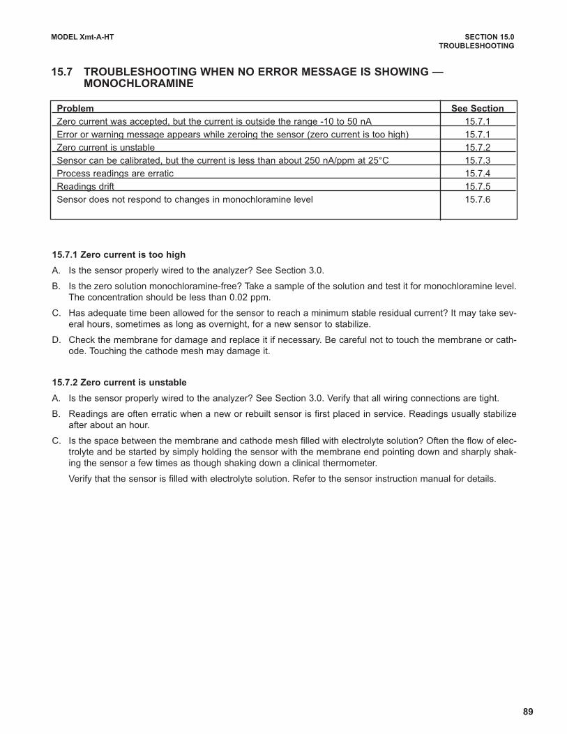
89
MODEL Xmt-A-HT SECTION 15.0
TROUBLESHOOTING
15.7 TROUBLESHOOTING WHEN NO ERROR MESSAGE IS SHOWING — MONOCHLORAMINE
15.7.1 Zero current is too high
A. Is the sensor properly wired to the analyzer? See Section 3.0.
B. Is the zero solution monochloramine-free? Take a sample of the solution and test it for monochloramine level.
The concentration should be less than 0.02 ppm.
C. Has adequate time been allowed for the sensor to reach a minimum stable residual current? It may take sev-
eral hours, sometimes as long as overnight, for a new sensor to stabilize.
D. Check the membrane for damage and replace it if necessary. Be careful not to touch the membrane or cath-
ode. Touching the cathode mesh may damage it.
15.7.2 Zero current is unstable
A. Is the sensor properly wired to the analyzer? See Section 3.0. Verify that all wiring connections are tight.
B. Readings are often erratic when a new or rebuilt sensor is first placed in service. Readings usually stabilize
after about an hour.
C. Is the space between the membrane and cathode mesh filled with electrolyte solution? Often the flow of elec-
trolyte and be started by simply holding the sensor with the membrane end pointing down and sharply shak-
ing the sensor a few times as though shaking down a clinical thermometer.
Verify that the sensor is filled with electrolyte solution. Refer to the sensor instruction manual for details.
Problem See Section
Zero current was accepted, but the current is outside the range -10 to 50 nA 15.7.1
Error or warning message appears while zeroing the sensor (zero current is too high) 15.7.1
Zero current is unstable 15.7.2
Sensor can be calibrated, but the current is less than about 250 nA/ppm at 25°C 15.7.3
Process readings are erratic 15.7.4
Readings drift 15.7.5
Sensor does not respond to changes in monochloramine level 15.7.6

90
MODEL Xmt-A-HT SECTION 15.0
TROUBLESHOOTING
15.7.3 Sensor can be calibrated, but the current is too low
A. Is the temperature low? The sensor current decreases about 5% for every °C drop in temperature.
B. Sensor current depends on the rate of sample flow past the sensor tip. If the flow is too low, monochloraminereadings will be low. Refer to the sensor instruction sheet for recommended sample flows.
C. Low current can be caused by lack of electrolyte flow to the cathode and membrane. See step C in Section15.7.2.
D. When was the sensor fill solution last replaced? The monochloramine sensor loses sensitivity, that is, it gen-erates less current per ppm of monochloramine, as it operates. Gradual loss of sensitivity can usually be com-pensated for by calibrating the sensor weekly. After about two months, the sensitivity will have dropped toabout 70% of its original value. At this point, the electrolyte solution and membrane should be replaced. Referto the sensor instruction manual.
E. Is the membrane fouled or coated? A dirty membrane inhibits diffusion of monochloramine through the mem-brane, reducing the sensor current and increasing the response time. Clean the membrane by rinsing it witha stream of water from a wash bottle. DO NOT use a membrane or tissue to wipe the membrane.
F. If cleaning the membrane does not improve the sensor response, replace the membrane and electrolyte solu-tion. See the sensor instruction sheet for details.
15.7.4 Process readings are erratic
A. Readings are often erratic when a new sensor or rebuilt sensor is first placed in service. The current usuallystabilizes after a few hours.
B. Is the sample flow within the recommended range? High sample flow may cause erratic readings. Refer to thesensor instruction sheet for recommended flow rates.
C. Verify that wiring is correct. Pay particular attention to shield and ground connections.
D. Is the membrane in good condition and is the sensor filled with electrolyte solution? Replace the fill solutionand electrolyte. Refer to the sensor instruction manual for details.
15.7.5 Readings drift
A. Is the sample temperature changing? Membrane permeability is a function of temperature. The time constantfor the sensor is about five minutes. Therefore, the reading may drift for a while after a sudden temperaturechange.
B. Is the membrane clean? For the sensor to work properly, monochloramine must diffuse freely through themembrane. A coating on the membrane will interfere with the passage of monochloramine, resulting in slowresponse. Clean the membrane by rinsing it with a stream of water from a wash bottle. DO NOT use a mem-brane or tissue to wipe the membrane.
C. Is the sample flow within the recommended range? Gradual loss of sample flow will cause a downward drift.
D. Is the sensor new or has it been recently serviced? New or rebuilt sensors may require several hours to sta-bilize.
E. Gradual downward drift is caused by depletion of the fill solution. Normally, calibrating the sensor every weekadequately compensates for the drift. After the sensor has been in service for several months, it will probablybe necessary to replace the fill solution and membrane. Refer to the sensor instruction manual for details.
15.7.6 Sensor does not respond to changes in monochloramine level.
A. Is the grab sample test accurate? Is the grab sample representative of the sample flowing to the sensor?
B. When was the sensor fill solution last replaced? The monochloramine sensor loses sensitivity, that is, it gen-erates less current per ppm of monochloramine, as it operates. After about two months, the sensitivity will havedropped to about 70% of its original value. If the fill solution is extremely old, the sensor may be completelynon-responsive to monochloramine. Replace the fill solution and membrane. See the sensor instruction man-ual for details.
C. Is the membrane clean? Clean the membrane with a stream of water and replace it if necessary.
D. Replace the sensor.

91
MODEL Xmt-A-HT SECTION 15.0
TROUBLESHOOTING
15.7.7 Readings are too low.
A. Was the sample tested as soon as it was taken? Monochloramine solutions are moderately unstable. Test the
sample immediately after collecting it. Avoid exposing the sample to sunlight.
B. When was the sensor fill solution last replaced? The monochloramine sensor loses sensitivity, that is, it gen-
erates less current per ppm of monochloramine, as it operates. Generally, calibrating the sensor every week
compensates for the gradual loss in sensitivity. After about two months, the sensitivity will have dropped to
about 70% of its original value. At this point, the electrolyte solution and membrane should be replaced. Refer
to the sensor instruction manual.
C. Low readings can be caused by zeroing the sensor before the residual current has reached a stable minimum
value. Residual current is the current the sensor generates even when no monochloramine is in the sample.
Because the residual current is subtracted from subsequent measured currents, zeroing before the current is
a minimum can lead to low results.
Example: The true residual current for a monochloramine sensor is 20 nA, and the sensitivity is 400 nA/ppm.Assume the measured current is 600 nA. The true concentration is (600-20)/400 or 1.45 ppm. If the sensorwas zeroed prematurely when the current was 40 nA, the measured concentration will be (600-40)/400 or 1.40ppm. The error is 3.5%. Suppose the measured current is 800 nA. The true concentration is 1.95 ppm, andthe measured concentration is 1.90 ppm. The error is now 2.6%. The absolute difference between the read-ing remains the same, 0.05 ppm.
D. Sensor response depends on flow. If the flow is too low, readings will be low and flow sensitive. Verify that theflow past the sensor equals or exceeds the minimum value. See the sensor instruction manual for recom-mended flows.

92
MODEL Xmt-A-HT SECTION 15.0
TROUBLESHOOTING
15.8 TROUBLESHOOTING WHEN NO FAULT MESSAGE IS SHOWING - OZONE
15.8.1 Zero current is too high
A. Is the sensor properly wired to the controller. See Section 3.0.
B. Is the zero solution ozone free? Test the zero solution for ozone level. The concentration should be less than0.02 ppm.
C. Has adequate time been allowed for the sensor to reach a minimum stable residual current? It may take sev-eral hours, sometimes as long as overnight, for a new sensor to stabilize.
D. Check the membrane for damage and replace it if necessary.
15.8.2 Zero current is unstable
A. Is the sensor properly wired to the analyzer? See Section 3.0. Verify that all wiring connections are tight.
B. Readings are often erratic when a new or rebuilt sensor is first placed in service. Readings usually stabilizeafter about an hour.
C. Is the space between the membrane and cathode filled with electrolyte solution and is the flow path betweenthe electrolyte reservoir and membrane clear? Often the flow of electrolyte and be started by simply holdingthe sensor with the membrane end pointing down and sharply shaking the sensor a few times as though shak-ing down a clinical thermometer.
If shaking does not work, try clearing the holes around the cathode stem. Hold the sensor with the membraneend pointing up. Unscrew the membrane retainer and remove the membrane assembly. Be sure the wood ringremains with the membrane assembly. Use the end of a straightened paper clip to clear the holes at the baseof the cathode stem. Replace the membrane.
Verify that the sensor is filled with electrolyte solution. Refer to the sensor instruction manual for details.
15.8.3 Sensor can be calibrated, but the current is too low
A. Sensor current is a strong function of temperature. The sensor current decreases about 3% for every °C dropin temperature.
B. Sensor current depends on the rate of sample flow past the sensor tip. If the flow is too low, ozone readingswill be low. Refer to the sensor instruction sheet for recommended sample flows.
C. Low current can be caused by lack of electrolyte flow to the cathode and membrane. See step C in Section15.8.2.
D. Is the membrane fouled or coated? A dirty membrane inhibits diffusion of ozone through the membrane, reduc-ing the sensor current and increasing the response time. Clean the membrane by rinsing it with a stream ofwater from a wash bottle or gently wipe the membrane with a soft tissue.
If cleaning the membrane does not improve the sensor response, replace the membrane and electrolyte solu-tion. If necessary, polish the cathode. See the sensor instruction sheet for details.
Problem See Section
Zero current was accepted, but the current is outside the range -10 to 10 nA 15.8.1
Error or warning message appears while zeroing the sensor (zero current is too high) 15.8.1
Zero current is unstable 15.8.2
Sensor can be calibrated, but the current is less than about 350 nA/ppm at 25°C 15.8.3
Process readings are erratic 15.8.4
Readings drift 15.8.5
Sensor does not respond to changes in ozone level 15.8.6
Ozone readings are too low 15.8.7
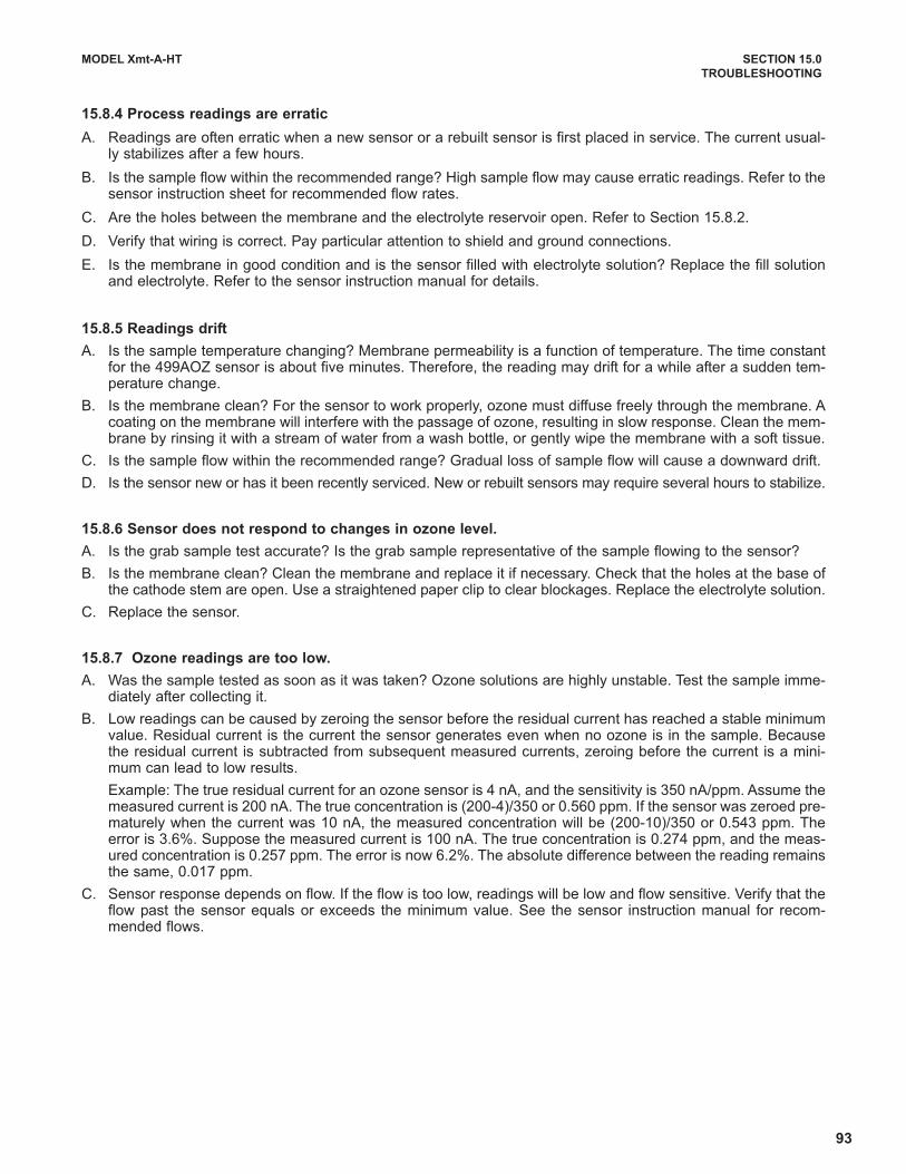
93
MODEL Xmt-A-HT SECTION 15.0
TROUBLESHOOTING
15.8.4 Process readings are erratic
A. Readings are often erratic when a new sensor or a rebuilt sensor is first placed in service. The current usual-ly stabilizes after a few hours.
B. Is the sample flow within the recommended range? High sample flow may cause erratic readings. Refer to thesensor instruction sheet for recommended flow rates.
C. Are the holes between the membrane and the electrolyte reservoir open. Refer to Section 15.8.2.
D. Verify that wiring is correct. Pay particular attention to shield and ground connections.
E. Is the membrane in good condition and is the sensor filled with electrolyte solution? Replace the fill solutionand electrolyte. Refer to the sensor instruction manual for details.
15.8.5 Readings drift
A. Is the sample temperature changing? Membrane permeability is a function of temperature. The time constantfor the 499AOZ sensor is about five minutes. Therefore, the reading may drift for a while after a sudden tem-perature change.
B. Is the membrane clean? For the sensor to work properly, ozone must diffuse freely through the membrane. Acoating on the membrane will interfere with the passage of ozone, resulting in slow response. Clean the mem-brane by rinsing it with a stream of water from a wash bottle, or gently wipe the membrane with a soft tissue.
C. Is the sample flow within the recommended range? Gradual loss of sample flow will cause a downward drift.
D. Is the sensor new or has it been recently serviced. New or rebuilt sensors may require several hours to stabilize.
15.8.6 Sensor does not respond to changes in ozone level.
A. Is the grab sample test accurate? Is the grab sample representative of the sample flowing to the sensor?
B. Is the membrane clean? Clean the membrane and replace it if necessary. Check that the holes at the base ofthe cathode stem are open. Use a straightened paper clip to clear blockages. Replace the electrolyte solution.
C. Replace the sensor.
15.8.7 Ozone readings are too low.
A. Was the sample tested as soon as it was taken? Ozone solutions are highly unstable. Test the sample imme-diately after collecting it.
B. Low readings can be caused by zeroing the sensor before the residual current has reached a stable minimumvalue. Residual current is the current the sensor generates even when no ozone is in the sample. Becausethe residual current is subtracted from subsequent measured currents, zeroing before the current is a mini-mum can lead to low results.
Example: The true residual current for an ozone sensor is 4 nA, and the sensitivity is 350 nA/ppm. Assume themeasured current is 200 nA. The true concentration is (200-4)/350 or 0.560 ppm. If the sensor was zeroed pre-maturely when the current was 10 nA, the measured concentration will be (200-10)/350 or 0.543 ppm. Theerror is 3.6%. Suppose the measured current is 100 nA. The true concentration is 0.274 ppm, and the meas-ured concentration is 0.257 ppm. The error is now 6.2%. The absolute difference between the reading remainsthe same, 0.017 ppm.
C. Sensor response depends on flow. If the flow is too low, readings will be low and flow sensitive. Verify that theflow past the sensor equals or exceeds the minimum value. See the sensor instruction manual for recom-mended flows.
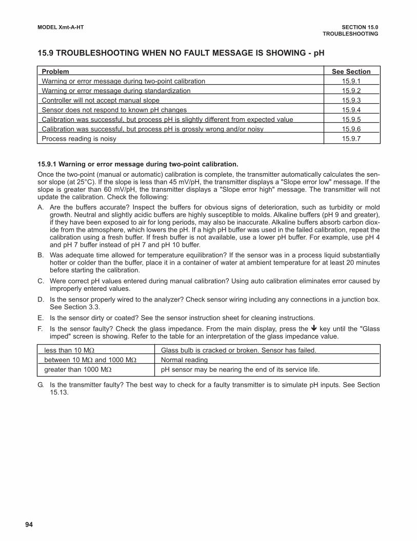
94
MODEL Xmt-A-HT SECTION 15.0
TROUBLESHOOTING
15.9 TROUBLESHOOTING WHEN NO FAULT MESSAGE IS SHOWING - pH
15.9.1 Warning or error message during two-point calibration.
Once the two-point (manual or automatic) calibration is complete, the transmitter automatically calculates the sen-sor slope (at 25°C). If the slope is less than 45 mV/pH, the transmitter displays a "Slope error low" message. If theslope is greater than 60 mV/pH, the transmitter displays a "Slope error high" message. The transmitter will notupdate the calibration. Check the following:
A. Are the buffers accurate? Inspect the buffers for obvious signs of deterioration, such as turbidity or moldgrowth. Neutral and slightly acidic buffers are highly susceptible to molds. Alkaline buffers (pH 9 and greater),if they have been exposed to air for long periods, may also be inaccurate. Alkaline buffers absorb carbon diox-ide from the atmosphere, which lowers the pH. If a high pH buffer was used in the failed calibration, repeat thecalibration using a fresh buffer. If fresh buffer is not available, use a lower pH buffer. For example, use pH 4and pH 7 buffer instead of pH 7 and pH 10 buffer.
B. Was adequate time allowed for temperature equilibration? If the sensor was in a process liquid substantiallyhotter or colder than the buffer, place it in a container of water at ambient temperature for at least 20 minutesbefore starting the calibration.
C. Were correct pH values entered during manual calibration? Using auto calibration eliminates error caused byimproperly entered values.
D. Is the sensor properly wired to the analyzer? Check sensor wiring including any connections in a junction box.See Section 3.3.
E. Is the sensor dirty or coated? See the sensor instruction sheet for cleaning instructions.
F. Is the sensor faulty? Check the glass impedance. From the main display, press the ê key until the "Glassimped" screen is showing. Refer to the table for an interpretation of the glass impedance value.
G. Is the transmitter faulty? The best way to check for a faulty transmitter is to simulate pH inputs. See Section15.13.
Problem See Section
Warning or error message during two-point calibration 15.9.1
Warning or error message during standardization 15.9.2
Controller will not accept manual slope 15.9.3
Sensor does not respond to known pH changes 15.9.4
Calibration was successful, but process pH is slightly different from expected value 15.9.5
Calibration was successful, but process pH is grossly wrong and/or noisy 15.9.6
Process reading is noisy 15.9.7
less than 10 MΩ Glass bulb is cracked or broken. Sensor has failed.
between 10 MΩ and 1000 MΩ Normal reading
greater than 1000 MΩ pH sensor may be nearing the end of its service life.
95
MODEL Xmt-A-HT SECTION 15.0
TROUBLESHOOTING
15.9.2 Warning or error message during two-point calibration.
During standardization, the millivolt signal from the pH cell is increased or decreased until it agrees with the pH
reading from a reference instrument. A unit change in pH requires an offset of about 59 mV. The controller limits
the offset to ±1400 mV. If the standardization causes an offset greater than ±1400 mV, the analyzer will display the
Calibration Error screen. The standardization will not be updated. Check the following:
A. Is the referee pH meter working and properly calibrated? Check the response of the referee sensor in buffers.
B. Is the process sensor working properly? Check the process sensor in buffers.
C. Is the sensor fully immersed in the process liquid? If the sensor is not completely submerged, it may be meas-
uring the pH of the liquid film covering the glass bulb and reference element. The pH of this film may be dif-
ferent from the pH of the bulk liquid.
D. Is the sensor fouled? The sensor measures the pH of the liquid adjacent to the glass bulb. If the sensor is
heavily fouled, the pH of liquid trapped against the bulb may be different from the bulk liquid.
E. Has the sensor been exposed to poisoning agents (sulfides or cyanides) or has it been exposed to extreme
temperature? Poisoning agents and high temperature can shift the reference voltage many hundred millivolts.
To check the reference voltage, see Section 15.15.
15.9.3 Controller will not accept manual slope.
If the sensor slope is known from other sources, it can be entered directly into the controller. The controller will not
accept a slope (at 25°) outside the range 45 to 60 mV/pH. If the user attempts to enter a slope less than 45 mV/pH,
the controller will automatically change the entry to 45. If the user attempts to enter a slope greater than 60 mV/pH,
the controller will change the entry to 60 mV/pH. See Section 15.9.1 for troubleshooting sensor slope problems.
15.9.4 Sensor does not respond to known pH changes.
A. Did the expected pH change really occur? If the process pH reading was not what was expected, check the
performance of the sensor in buffers. Also, use a second pH meter to verify the change.
B. Is the sensor properly wired to the analyzer?
C. Is the glass bulb cracked or broken? Check the glass electrode impedance. See Section 15.2.2.
D. Is the analyzer working properly. Check the analyzer by simulating the pH input.
15.9.5 Calibration was successful, but process pH is slightly different from expected value.
Differences between pH readings made with an on-line instrument and a laboratory or portable instrument are nor-mal. The on-line instrument is subject to process variables, for example ground potentials, stray voltages, and ori-entation effects that may not affect the laboratory or portable instrument. To make the process reading agree witha reference instrument, see Section 14.4.

96
MODEL Xmt-A-HT SECTION 15.0
TROUBLESHOOTING
15.9.6 Calibration was successful, but process pH is grossly wrong and/or noisy.
Grossly wrong or noisy readings suggest a ground loop (measurement system connected to earth ground at morethan one point), a floating system (no earth ground), or noise being brought into the analyzer by the sensor cable.The problem arises from the process or installation. It is not a fault of the analyzer. The problem should disappearonce the sensor is taken out of the system. Check the following:
A. Is a ground loop present?
1. Verify that the system works properly in buffers. Be sure there is no direct electrical connection betweenthe buffer containers and the process liquid or piping.
2. Strip back the ends of a heavy gauge wire. Connect one end of the wire to the process piping or place itin the process liquid. Place the other end of the wire in the container of buffer with the sensor. The wiremakes an electrical connection between the process and sensor.
3. If offsets and noise appear after making the connection, a ground loop exists.
B. Is the process grounded?
1. The measurement system needs one path to ground: through the process liquid and piping. Plastic pip-ing, fiberglass tanks, and ungrounded or poorly grounded vessels do not provide a path. A floating systemcan pick up stray voltages from other electrical equipment.
2. Ground the piping or tank to a local earth ground.
3. If noise still persists, simple grounding is not the problem. Noise is probably being carried into the instru-ment through the sensor wiring.
C. Simplify the sensor wiring.
1. First, verify that pH sensor wiring is correct. Note that it is not necessary to jumper the solution ground andreference terminals.
2. Disconnect all sensor wires at the analyzer except pH/mV IN, REFERENCE IN, RTD IN and RTDRETURN. See the wiring diagrams in Section 3.0. If the sensor is wired to the analyzer through a remotejunction box containing a preamplifier, disconnect the wires at the sensor side of the junction box.
3. Tape back the ends of the disconnected wires to keep them from making accidental connections with otherwires or terminals.
4. Connect a jumper wire between the RTD RETURN and RTD SENSE terminals (see wiring diagrams inSection 3.0).
5. If noise and/or offsets disappear, the interference was coming into the analyzer through one of the sensorwires. The system can be operated permanently with the simplified wiring.
D. Check for extra ground connections or induced noise.
1. If the sensor cable is run inside conduit, there may be a short between the cable and the conduit. Re-runthe cable outside the conduit. If symptoms disappear, there is a short between the cable and the conduit.Likely a shield is exposed and touching the conduit. Repair the cable and reinstall it in the conduit.
2. To avoid induced noise in the sensor cable, run it as far away as possible from power cables, relays, andelectric motors. Keep sensor wiring out of crowded panels and cable trays.
3. If ground loops persist, consult the factory. A visit from a technician may be required to solve the problem.
15.9.7 Process pH readings are noisy.
A. Is the sensor dirty or fouled? Suspended solids in the sample can coat the reference junction and interfere withthe electrical connection between the sensor and the process liquid. The result is often a noisy reading.
B. Is the sensor properly wired to the analyzer? See Section 3.0.
C. Is a ground loop present? Refer to Section 15.9.6.

97
MODEL Xmt-A-HT SECTION 15.0
TROUBLESHOOTING
15.10 TROUBLESHOOTING NOT RELATED TO MEASUREMENT PROBLEMS
Problem Action
Incorrect current output 1. Verify that output load is within the values shown in
Figure 2.5.
2. For minor errors, trim the output (see Section 7.3.6)
Display too light or too dark Change contrast (see Section 7.10)
“Enter Security Code” shown in display Transmitter has password protection
(see Sections 5.4 and 7.6)
“Hold” showing in display Transmitter is in hold (see Section 5.5)
“Current Output for Test:” showing in display Transmitter is simulating outputs (see Section 7.3.5)
15.11 SIMULATING INPUTS - DISSOLVED OXYGEN
To check the performance of the controller, use a decade box to simulate the current from the oxygen sensor.
A. Disconnect the anode and cathode leads from terminals 11 and 12 on TB1 and connect a decade box as
shown in Figure 15-1. It is not necessary to disconnect the RTD leads.
B. Set the decade box to the resistance shown in the table.
C. Note the sensor current. To view the sensor current from the
main display, press ê until the Input Current screen
appears. Note the units: μA is microamps, nA is nanoamps.
D. Change the decade box resistance and verify that the cor-
rect current is shown. Calculate current from the equation:
current (μA) =
Sensor Polarizing Voltage Resistance Expected current
499ADO -675 mV 34 kΩ 20 μA
499A TrDO -800 mV 20 kΩ 40 μA
Hx438 and Gx448 -675 mV 8.4 MΩ 80 nA
voltage (mV)
resistance (kΩ)
FIGURE 15-1. Simulate Dissolved Oxygen

98
MODEL Xmt-A-HT SECTION 15.0
TROUBLESHOOTING
15.12 SIMULATING INPUTS - OTHER AMPEROMETRIC MEASUREMENTS
To check the performance of the controller, use a decade box and a battery to simulate the current from the sen-
sor. The battery, which opposes the polarizing voltage, is necessary to ensure that the sensor current has the cor-
rect sign.
A. Disconnect the anode and cathode leads from terminals 1 and 2 on TB3 and connect a decade box and bat-
tery as shown in Figure 15-2. It is not necessary to disconnect the RTD leads.
B. Set the decade box to the resistance shown in the table.
C. Note the sensor current. It should be close to the value
in the table. The actual value depends of the voltage of
the battery. To view the sensor current from the main
display, press ê until the Input Current screen
appears. Note the units: μA is microamps, nA is
nanoamps.
D. Change the decade box resistance and verify that thecorrect current is shown. Calculate current from theequation:
current (μA) =
The voltage of a fresh 1.5 volt battery is about 1.6 volt(1600 mV).
Sensor Polarizing Voltage Resistance Expected current
499ACL-01 (free chlorine) 200 mV 28 MΩ 500 nA
499ACL-02 (total chlorine) 250 mV 675 kΩ 2000 nA
499ACL-03 (monochloramine) 400 mV 3 MΩ 400 nA
499AOZ 250 mV 2.7 MΩ 500 nA
Vbattery - Vpolarizing (mV)
resistance (kΩ)
FIGURE 15-2. Simulate Chlorine and Ozone
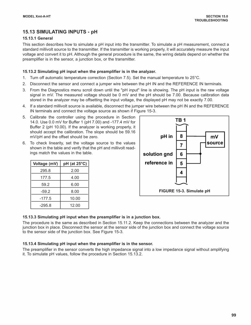
99
MODEL Xmt-A-HT SECTION 15.0
TROUBLESHOOTING
15.13 SIMULATING INPUTS - pH
15.13.1 General
This section describes how to simulate a pH input into the transmitter. To simulate a pH measurement, connect a
standard millivolt source to the transmitter. If the transmitter is working properly, it will accurately measure the input
voltage and convert it to pH. Although the general procedure is the same, the wiring details depend on whether the
preamplifier is in the sensor, a junction box, or the transmitter.
15.13.2 Simulating pH input when the preamplifier is in the analyzer.
1. Turn off automatic temperature correction (Section 7.5). Set the manual temperature to 25°C.
2. Disconnect the sensor and connect a jumper wire between the pH IN and the REFERENCE IN terminals.
3. From the Diagnostics menu scroll down until the "pH input" line is showing. The pH input is the raw voltage
signal in mV. The measured voltage should be 0 mV and the pH should be 7.00. Because calibration data
stored in the analyzer may be offsetting the input voltage, the displayed pH may not be exactly 7.00.
4. If a standard millivolt source is available, disconnect the jumper wire between the pH IN and the REFERENCE
IN terminals and connect the voltage source as shown if Figure 15-3.
5. Calibrate the controller using the procedure in Section
14.0. Use 0.0 mV for Buffer 1 (pH 7.00) and -177.4 mV for
Buffer 2 (pH 10.00). If the analyzer is working properly, it
should accept the calibration. The slope should be 59.16
mV/pH and the offset should be zero.
6. To check linearity, set the voltage source to the values
shown in the table and verify that the pH and millivolt read-
ings match the values in the table.
15.13.3 Simulating pH input when the preamplifier is in a junction box.
The procedure is the same as described in Section 15.11.2. Keep the connections between the analyzer and thejunction box in place. Disconnect the sensor at the sensor side of the junction box and connect the voltage sourceto the sensor side of the junction box. See Figure 15-3.
15.13.4 Simulating pH input when the preamplifier is in the sensor.
The preamplifier in the sensor converts the high impedance signal into a low impedance signal without amplifyingit. To simulate pH values, follow the procedure in Section 15.13.2.
Voltage (mV) pH (at 25°C)
295.8 2.00
177.5 4.00
59.2 6.00
-59.2 8.00
-177.5 10.00
-295.8 12.00
FIGURE 15-3. Simulate pH

100
MODEL Xmt-A-HT SECTION 15.0
TROUBLESHOOTING
15.14 SIMULATING TEMPERATURE
15.14.1 General.
The Xmt-A-HT controller accepts either a Pt100 RTD (for
pH, 499ADO, 499ATrDO, 499ACL-01, 499ACL-02,
499ACL-03, and 499AOZ sensors) or a 22k NTC thermis-
tor (for Hx438 and Gx448 DO sensors and most steam-
sterilizable DO sensors from other manufacturers). The
Pt100 RTD is in a three-wire configuration. See Figure 15-
4. The 22k thermistor has a two-wire configuration.
15.14.2 Simulating temperature
To simulate the temperature input, wire a decade box to the
analyzer or junction box as shown in Figure 15-5.
To check the accuracy of the temperature measurement,
set the resistor simulating the RTD to the values indicated
in the table and note the temperature readings. The meas-
ured temperature might not agree with the value in the
table. During sensor calibration an offset might have been
applied to make the measured temperature agree with a
standard thermometer. The offset is also applied to the
simulated resistance. The controller is measuring tempera-
ture correctly if the difference between measured tempera-
tures equals the difference between the values in the table
to within ±0.1°C.
For example, start with a simulated resistance of 103.9 Ω,
which corresponds to 10.0°C. Assume the offset from the
sensor calibration was -0.3 Ω. Because of the offset, the
analyzer calculates temperature using 103.6 Ω. The result
is 9.2°C. Now change the resistance to 107.8 Ω, which cor-
responds to 20.0°C. The analyzer uses 107.5 Ω to calcu-
late the temperature, so the display reads 19.2°C. Because
the difference between the displayed temperatures
(10.0°C) is the same as the difference between the simu-
lated temperatures, the analyzer is working correctly.
Temp. (°C) Pt 100 (Ω) 22k NTC (kΩ)
0 100.0 64.88
10 103.9 41.33
20 107.8 26.99
25 109.7 22.00
30 111.7 18.03
40 115.5 12.31
50 119.4 8.565
60 123.2 6.072
70 127.1 4.378
80 130.9 3.208
85 132.8 2.761
90 134.7 2.385
100 138.5 1.798
FIGURE 15-4. Three-Wire RTD Configuration.
Although only two wires are required to connect the RTDto the analyzer, using a third (and sometimes fourth) wireallows the analyzer to correct for the resistance of thelead wires and for changes in the lead wire resistancewith temperature.
FIGURE 15-5. Simulating RTD Inputs.
The figure shows wiring connections for sensors con-taining a Pt 100 RTD.
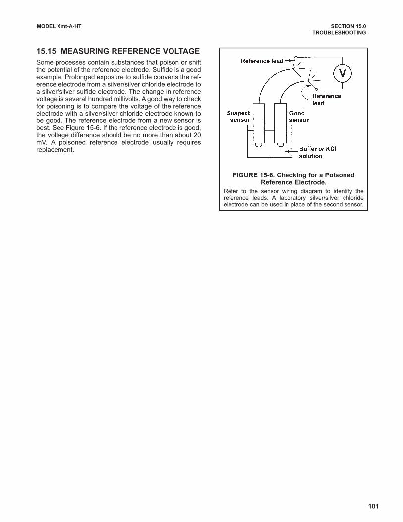
101
MODEL Xmt-A-HT SECTION 15.0
TROUBLESHOOTING
15.15 MEASURING REFERENCE VOLTAGE
Some processes contain substances that poison or shiftthe potential of the reference electrode. Sulfide is a goodexample. Prolonged exposure to sulfide converts the ref-erence electrode from a silver/silver chloride electrode toa silver/silver sulfide electrode. The change in referencevoltage is several hundred millivolts. A good way to checkfor poisoning is to compare the voltage of the referenceelectrode with a silver/silver chloride electrode known tobe good. The reference electrode from a new sensor isbest. See Figure 15-6. If the reference electrode is good,the voltage difference should be no more than about 20mV. A poisoned reference electrode usually requiresreplacement.
FIGURE 15-6. Checking for a PoisonedReference Electrode.
Refer to the sensor wiring diagram to identify thereference leads. A laboratory silver/silver chlorideelectrode can be used in place of the second sensor.

102
MODEL Xmt-A-HT SECTION 16.0
MAINTENANCE
SECTION 16.0
MAINTENANCE
TABLE 16-1. REPLACEMENT PARTS FOR SOLU COMP XMT (PANEL MOUNT VERSION)
PART NUMBER DESCRIPTION SHIPPING WEIGHT
23823-00 Panel mounting kit, includes four brackets and four set screws 2 lb/1.0 kg
33654-00 Gasket, front, for panel mount version 2 lb/1.0 kg
33658-00 Gasket, rear cover, for panel mount version 2 lb/1.0 kg
TABLE 16-2. REPLACEMENT PARTS FOR SOLU COMP XMT (PIPE/SURFACE MOUNT VERSION)
PART NUMBER DESCRIPTION SHIPPING WEIGHT
33655-00 Gasket for pipe/surface mount version 2 lb/1.0 kg
23833-00 Surface mount kit, consists of four self tapping screws and 1 lb/0.5 kg
four O-rings
16.1 OVERVIEW
The Solu Comp Xmt needs little routine maintenance. The calibration of the analyzer and sensor should be
checked periodically. To recalibrate the sensor and analyzer, refer to sections 9 through 14.
16.2 REPLACEMENT PARTS
Only a few components of the analyzer are replaceable. Refer to the tables below. Circuit boards, display, and
enclosure are not replaceable.
103
MODEL Xmt-A-HT SECTION 17.0
RETURN OF MATERIAL
SECTION 17.0
RETURN OF MATERIAL
17.1 GENERAL.
To expedite the repair and return of instruments, proper communication between the customer and the factory is
important. Before returning a product for repair, call 1-949-757-8500 for a Return Materials Authorization (RMA)
number.
17.2 WARRANTY REPAIR.
The following is the procedure for returning instruments still under warranty:
1. Call Rosemount Analytical for authorization.
2. To verify warranty, supply the factory sales order number or the original purchase order number. In the case
of individual parts or sub-assemblies, the serial number on the unit must be supplied.
3. Carefully package the materials and enclose your “Letter of Transmittal” (see Warranty). If possible, pack the
materials in the same manner as they were received.
4. Send the package prepaid to:
Emerson Process Management
Liquid Division
2400 Barranca Parkway
Irvine, CA 92606
Attn: Factory Repair
RMA No. ____________
Mark the package: Returned for Repair
Model No. ____
17.3 NON-WARRANTY REPAIR.
The following is the procedure for returning for repair instruments that are no longer under warranty:
1. Call Rosemount Analytical for authorization.
2. Supply the purchase order number, and make sure to provide the name and telephone number of the individ-
ual to be contacted should additional information be needed.
3. Do Steps 3 and 4 of Section 17.2.
NOTE
Consult the factory for additional information regarding service or repair.
IMPORTANT
Please see second section of “Return of
Materials Request” form. Compliance with
the OSHA requirements is mandatory for
the safety of all personnel. MSDS forms
and a certification that the instruments have
been disinfected or detoxified are required.

104
MODEL Xmt-A-HT APPENDIX A
APPENDIX A
BAROMETRIC PRESSURE AS A FUNCTION OF ALTITUDE
The table shows how barometric pressure changes with altitude. Pressure values do not take into account
humidity and weather fronts.
Altitude Barometric Pressure
m ft bar mm Hg in Hg kPa
0 0 1.013 760 29.91 101.3
250 820 0.983 737 29.03 98.3
500 1640 0.955 716 28.20 95.5
750 2460 0.927 695 27.37 92.7
1000 3280 0.899 674 26.55 89.9
1250 4100 0.873 655 25.77 87.3
1500 4920 0.846 635 24.98 84.6
1750 5740 0.821 616 24.24 82.1
2000 6560 0.795 596 23.47 79.5
2250 7380 0.771 579 22.78 77.1
2500 8200 0.747 560 22.06 74.7
2750 9020 0.724 543 21.38 72.4
3000 9840 0.701 526 20.70 70.1
3250 10,660 0.679 509 20.05 67.9
3500 11,480 0.658 494 19.43 65.8

105
A Worldwide Network of Sales and Service
Emerson Process Management’s field sales offices are your source for more information on the fill line of Rosemount Analyticalproducts. Field sales personnel will work closely with you to supply technical data and application information.
For more information, please contact your nearest Emerson Process Management sales office.
Immediate, Reliable Analytical Support Now there’s a way to quickly get the right answers for your liquid analytical instrumentation questions: the AnalyticalCustomer Support Center.
Our staff of trained professionals is ready to provide the information you need. If you are placing an order, verifying delivery,requesting application information, or just want to contact an Emerson Process Management representative, a call to theCustomer Support Center will provide you with the right people, the right answers, right now.
The right people, the right answers, right now.
THE AMERICAS -HEADQUARTERS
Emerson Process Management
Rosemount Analytical Inc.
Liquid Center of Excellence
2400 Barranca Parkway
Irvine, CA 92606
Phone: +1.949.757.8500
Toll Free: +1.800.854.8257
Fax: +1.949.474.7250
ASIA-PACIFIC
Emerson Process Management
Asia Pacific Private Ltd.
1 Pandan Crescent
Singapore 0512
Republic of Singapore
Phone: 65.777.8211
Fax: 65.777.0947
EUROPE
Emerson Process Management AG
Blegistrasse 21
CH-6341 Baar-Walterswil
Switzerland
T 41.41.768.6111
T 41.41.761.8740
VISIT OUR WEBSITE ATwww.rosemountanalytical.com
GERMANY
Emerson Process Management Process
Gas Analyzer Center of Excellence
GmbH & Co. OHG
Industriestrasse 1
63594 Hasselroth
Germany
T 49.6055.884.0
F 49.6055.884.20
LATIN AMERICA
Emerson Process Management
Rosemount Analytical
10241 West Little York, Suite #200
Houston, TX 77040 USA
T 713.467.6000
F 713.827.3328
MIDDLE EAST AND AFRICA
Emerson Process Management
EPM Building
P. O. Box 17033
Jebe Ali Free Zone
Dubai, United Arab Emirates
T 971.4.8835235
F 971.4.8835312
106
WARRANTY
Goods and part(s) (excluding consumables) manufactured by Seller are warranted to be free from defects in workman-
ship and material under normal use and service for a period of twelve (12) months from the date of shipment by Seller.
Consumables, pH electrodes, membranes, liquid junctions, electrolyte, O-rings, etc. are warranted to be free from defects
in workmanship and material under normal use and service for a period of ninety (90) days from date of shipment by Seller.
Goods, part(s) and consumables proven by Seller to be defective in workmanship and / or material shall be replaced or
repaired, free of charge, F.O.B. Seller's factory provided that the goods, parts(s), or consumables are returned to Seller's
designated factory, transportation charges prepaid, within the twelve (12) month period of warranty in the case of goods
and part(s), and in the case of consumables, within the ninety (90) day period of warranty. This warranty shall be in effect
for replacement or repaired goods, part(s) and consumables for the remaining portion of the period of the twelve (12)
month warranty in the case of goods and part(s) and the remaining portion of the ninety (90) day warranty in the case of
consumables. A defect in goods, part(s) and consumables of the commercial unit shall not operate to condemn such com-
mercial unit when such goods, parts(s) or consumables are capable of being renewed, repaired or replaced.
The Seller shall not be liable to the Buyer, or to any other person, for the loss or damage, directly or indirectly, arising
from the use of the equipment or goods, from breach of any warranty or from any other cause. All other warranties,
expressed or implied are hereby excluded.
IN CONSIDERATION OF THE STATED PURCHASE PRICE OF THE GOODS, SELLER GRANTS ONLY THE ABOVE
STATED EXPRESS WARRANTY. NO OTHER WARRANTIES ARE GRANTED INCLUDING, BUT NOT LIMITED TO,
EXPRESS AND IMPLIED WARRANTIES OF MERCHANTABILITY AND FITNESS FOR A PARTICULAR PURPOSE.
RETURN OF MATERIAL
Material returned for repair, whether in or out of warranty, should be shipped prepaid to:
Emerson Process Management
2400 Barranca Parkway
Irvine, CA 92606
The shipping container should be marked:
Return for Repair
Model _______________________________
The returned material should be accompanied by a letter of transmittal which should include the following information
(make a copy of the "Return of Materials Request" found on the last page of the Manual and provide the following there-
on):
1. Location type of service, and length of time of service of the device.
2. Description of the faulty operation of the device and the circumstances of the failure.
3. Name and telephone number of the person to contact if there are questions about the returned material.
4. Statement as to whether warranty or non-warranty service is requested.
5. Complete shipping instructions for return of the material.
Adherence to these procedures will expedite handling of the returned material and will prevent unnecessary additional
charges for inspection and testing to determine the problem with the device.
If the material is returned for out-of-warranty repairs, a purchase order for repairs should be enclosed.
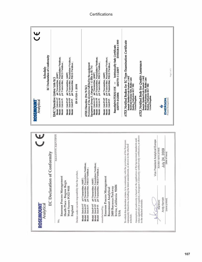
107
Certifications

108
Credit Cards for U.S. Purchases Only.
The right people,the right answers,right now. ON-LINE ORDERING NOW AVAILABLE ON OUR WEB SITE
http://www.rosemountanalytical.com
Specifications subject to change without notice.
8
Emerson Process Management
2400 Barranca Parkway
Irvine, CA 92606 USA
Tel: (949) 757-8500
Fax: (949) 474-7250
http://www.rosemountnanlytical.com
© Rosemount Analytical Inc. 2012