Embed Size (px)
Citation preview

1
Diffusion - Mass transport by atomic motion
Mechanisms • Gases & Liquids – random (Brownian) motion • Solids – vacancy diffusion or interstitial diffusion
Interdiffusion: In an alloy, atoms tend to migrate from regions of high conc. to regions of low conc.
Self-diffusion: In an elemental solid, atoms also migrate.

2
Initially
Adapted from Figs. 5.1 and 5.2, Callister 7e.
After some time

3
Label some atoms After some time
A
B
C
D A
B
C
D
4
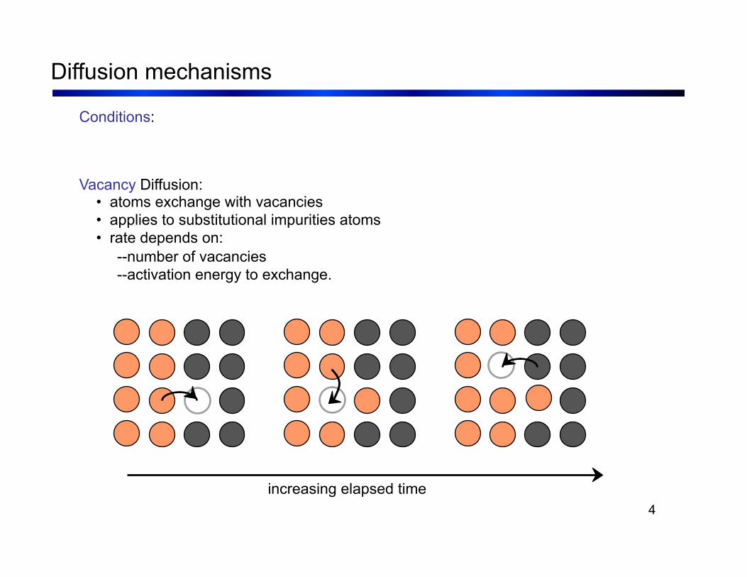
Vacancy Diffusion: • atoms exchange with vacancies • applies to substitutional impurities atoms • rate depends on: --number of vacancies --activation energy to exchange.
increasing elapsed time
Conditions:

5
• Simulation of interdiffusion across an interface:
• Rate of substitutional diffusion depends on: --vacancy concentration --frequency of jumping.
(Courtesy P.M. Anderson)

6
How do we quantify the amount or rate of diffusion?
Measured empirically • Make thin film (membrane) of known surface area • Impose concentration gradient • Measure how fast atoms or molecules diffuse through the membrane

7
C1
C2
x
C1
C2
x1 x2
Flux proportional to concentration gradient = dxdC

8
• Diffusion coefficient increases with increasing T.

9
Diffusion FASTER for...
• open crystal structures
• materials w/secondary bonding
• smaller diffusing atoms
• lower density materials
Diffusion SLOWER for...
• close-packed structures
• materials w/covalent bonding
• larger diffusing atoms
• higher density materials

10
• Shear stress, τ:
Area, A
F t
F t
F s
F
F
F s
• Tensile stress, σ:
Area, A
F t
F t

11
• Tensile strain: • Lateral strain:
• Shear strain:
θ
90º
90º - θ y
Δx θ γ = Δx/y = tan
Adapted from Fig. 6.1 (a) and (c), Callister 7e.
δ /2
δ L /2
L o w
o

12
• Modulus of Elasticity, E: (also known as Young's modulus)
σ
Linear-
elastic
E
ε
F
F
simple tension test

13
• Poisson's ratio, ν:
– ν > 0.50 density increases – ν < 0.50 density decreases (voids form)
εL
ε
- ν

14
• Simple tension test:
engineering stress, σ
engineering strain, ε
Elastic+Plastic at larger stress
permanent (plastic) after load is removed
εp
plastic strain
Elastic
initially
Adapted from Fig. 6.10 (a), Callister 7e.

15
Adapted from Fig. 6.10 (a), Callister 7e.
tensile stress, σ
engineering strain, ε

16
• Metals: occurs when noticeable necking starts. • Polymers: occurs when polymer backbone chains are aligned and about to break.
σy
strain
Typical response of a metal
eng
inee
ring
stre
ss
engineering strain
• Maximum stress on engineering stress-strain curve.

17
• Plastic tensile strain at failure:
Adapted from Fig. 6.13, Callister 7e.
Engineering tensile strain, ε
Engineering tensile stress, σ
smaller %EL
larger %EL Lf
Ao Af Lo

18
• Energy to break a unit volume of material • Approximate by the area under the stress-strain curve.
Adapted from Fig. 6.13, Callister 7e.
Engineering tensile strain, ε
Engineering tensile stress, σ

19
• Resistance to permanently indenting the surface. • Large hardness means: --resistance to plastic deformation or cracking in compression. --better wear properties.
e.g., 10 mm sphere
apply known force measure size of indent after removing load
d D Smaller indents mean larger hardness.
increasing hardness
most plastics
brasses Al alloys
easy to machine steels file hard
cutting tools
nitrided steels diamond

20
Table 6.5

21
• Cubic & hexagonal metals - plastic deformation by plastic shear or slip where one plane of atoms slides over adjacent plane by defect motion (dislocations).
Adapted from Fig. 7.1, Callister 7e.

22
Edge dislocation
Screw dislocation
Adapted from Fig. 7.2, Callister 7e.

23
Adapted from Fig. 7.6, Callister 7e.
24
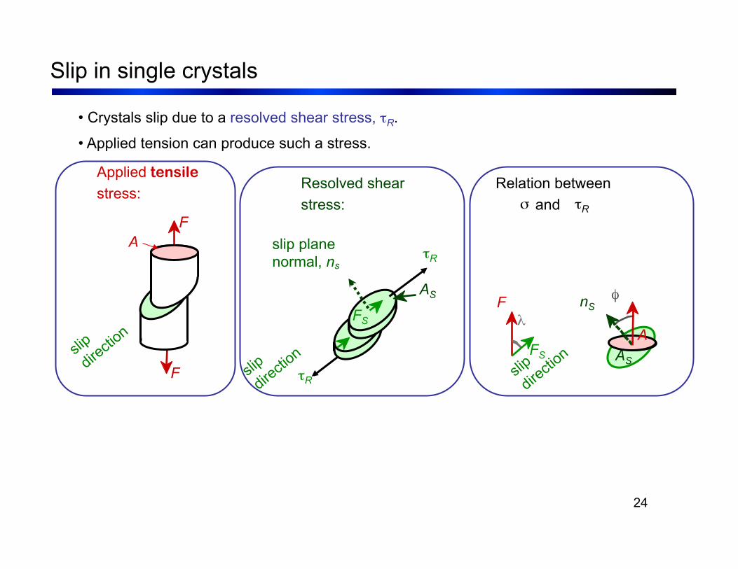
• Crystals slip due to a resolved shear stress, τR.
• Applied tension can produce such a stress.
slip plane normal, ns
Resolved shear stress:
AS
τR
τR
FS
Relation between σ and τR
λ F
FS
φ nS
AS A
Applied tensile stress:
F A
F

25
• Condition for dislocation motion:
• Crystal orientation can make it easy or hard to move dislocation
σ σ σ

26
• Stronger - grain boundaries pin deformations
• Slip planes & directions (λ, φ) change from one crystal to another.
• τR will vary from one crystal to another.
• The crystal with the largest τR yields first.
• Other (less favorably oriented) crystals yield later.
Adapted from Fig. 7.10, Callister 7e. (Fig. 7.10 is courtesy of C. Brady, National Bureau of Standards [now the National Institute of Standards and Technology, Gaithersburg, MD].)
σ
300 µm

27
• Grain boundaries are barriers to slip.
• Barrier "strength” increases with increasing angle of misorientation.
• Smaller grain size: more barriers to slip.
• Hall-Petch Equation:
Adapted from Fig. 7.14, Callister 7e. (Fig. 7.14 is from A Textbook of Materials Technology, by Van Vlack, Pearson Education, Inc., Upper Saddle River, NJ.)

28
Adapted from Fig. 7.4, Callister 7e.

29
Adapted from Fig. 7.5, Callister 7e.

30
Adapted from Fig. 7.17, Callister 7e.

31
Adapted from Fig. 7.18, Callister 7e.

32
• Room temperature deformation.
• Common forming operations change the cross sectional area:
Adapted from Fig. 11.8, Callister 7e.
-Forging
A o A d
force die
blank
force -Drawing
tensile force A o
A d die
die
-Extrusion
ram billet container
container force die holder
die
A o
A d extrusion
-Rolling
roll A o
A d roll

33
Adapted from Fig. 7.20, Callister 7e.
As cold work is increased


![Untitled-1 [] · No Vacancy No Vacancy No Vacancy OBC 47.758 55.89 52.33 No Vacancy 55.13 52.46 52.33 53.00 43.80 No Vacancy No Vacancy sc 45.331 58.33 No Vacancy No Vacancy 50.67](https://img.dokumen.tips/doc/110x75/5fb0660e3185c15b9b1e7853/untitled-1-no-vacancy-no-vacancy-no-vacancy-obc-47758-5589-5233-no-vacancy.jpg)