Embed Size (px)
Citation preview

Solid State Power Amplifiers for VHF April 2014
Over the past few years the rise in popularity and availability of relatively inexpensive Solid State Power Amplifiers (SSPA) have allowed many hams to migrate from valves towards Solid-State Field Effect Transistors (FETs) for high-power VHF applications. They are readily available and moderately easy to set up for even the least technical of us. Best of all there is a huge pool of helpful hams available world-wide to help out should questions or problems be encountered along the way.
A basic 1kW output amplifier for 6M, 4M, or even 2M has allowed many operators to do things we could only dream of a few years ago. Operating modes such as EME, MS, Au, and TEP are now effective and affordable for many of us now for the very first time. Making the 10dB jump from 100W to 1kW can have huge benefits to successfully operating DX on the VHF bands.
In just the past few years VO1KS and N1RJX have cumulatively answered hundreds of emails covering everything from SSPA availability to the technical “How to” steps required to put one of these amplifiers on the air. What follows are just a few preliminary notes to help you understand what some of your SSPA options are and what it may take to go from pallet to on the air.
Popular SSPA Options
There seems to be three popular types of high-power SSPA finding their way into the modern VHF ham shack.
1.Fully assembled and nearly ready to use SSPA units made by Larcan.
2.Fully assembled and nearly ready to use SSPA units made by Harris.
3.SSPA kits and modules based on the Freescale FET devices.
The Larcan and Harris SSPA are commercial TV broadcast equipment which have found their way into the amateur surplus market after much of the television industry has switched from analog to digital transmission format. Freescale FET based SSPAs may be found in kit or assembled module form from amateurs such as W6PQL.
“Wow this looks cool how can I make it work in Ham Radio?”
Which SSPA is best for you is purely a personal choice. Here is a little information on all three popular types to help you decide which may be best for you. Getting the Larcan or Harris SSPAs on the air will take approximately the same time, resources and work. With the Larcan and Harris SSPAs the requirements are basically; changing out the input/output RF connectors, providing some form of T/R RF switching, providing adequate cooling, and providing a high-current 50VDC power supply. Getting a Freescale device may be much more involved as the amplifiers may be purchased as kits (raw parts) or pre-assembled modules, or ready to go units. Whichever SSPA you purchase, check on availability of replacement parts. Everything breaks
eventually so plan ahead. Make sure you don't end up with an expensive door stop that cannot be repaired. A brief outline and links for the major sites featuring information on each are as follows.
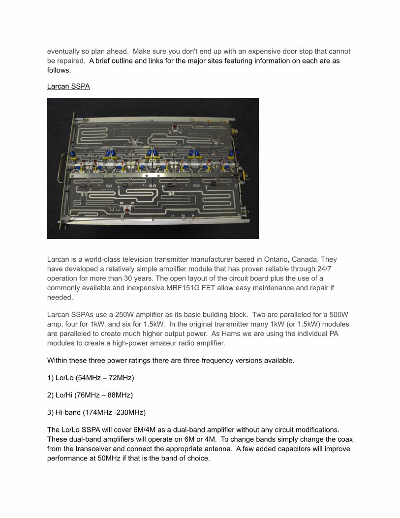
Larcan SSPA
Larcan is a world-class television transmitter manufacturer based in Ontario, Canada. They have developed a relatively simple amplifier module that has proven reliable through 24/7 operation for more than 30 years. The open layout of the circuit board plus the use of a commonly available and inexpensive MRF151G FET allow easy maintenance and repair if needed.
Larcan SSPAs use a 250W amplifier as its basic building block. Two are paralleled for a 500W amp, four for 1kW, and six for 1.5kW. In the original transmitter many 1kW (or 1.5kW) modules are paralleled to create much higher output power. As Hams we are using the individual PA modules to create a high-power amateur radio amplifier.
Within these three power ratings there are three frequency versions available.
1) Lo/Lo (54MHz – 72MHz)
2) Lo/Hi (76MHz – 88MHz)
3) Hi-band (174MHz -230MHz)
The Lo/Lo SSPA will cover 6M/4M as a dual-band amplifier without any circuit modifications. These dual-band amplifiers will operate on 6M or 4M. To change bands simply change the coax from the transceiver and connect the appropriate antenna. A few added capacitors will improve performance at 50MHz if that is the band of choice.
The Lo/Hi can be converted to a Lo/Lo by changing out approximately 40 capacitors.
The Hi-band amplifier (174MHz – 230MHz) will cover 222MHz with no circuit modifications. http://members.rennlist.org/warren/LarcanAmplifiers.html
The 1kW Lo/Lo and Lo/Hi SSPA can be modified to cover 2M. The conversion was pioneered by Brian WA1ZMS, and further refined by others including WA3LBI and VO1KS. Additional information may be found at the following link:http://members.rennlist.org/warren/2mLarcan.html
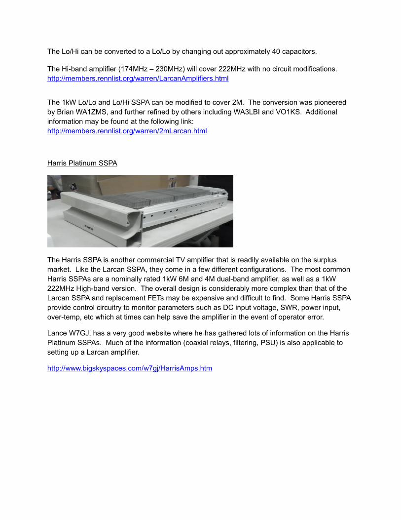
Harris Platinum SSPA
The Harris SSPA is another commercial TV amplifier that is readily available on the surplus market. Like the Larcan SSPA, they come in a few different configurations. The most common Harris SSPAs are a nominally rated 1kW 6M and 4M dual-band amplifier, as well as a 1kW 222MHz High-band version. The overall design is considerably more complex than that of the Larcan SSPA and replacement FETs may be expensive and difficult to find. Some Harris SSPA provide control circuitry to monitor parameters such as DC input voltage, SWR, power input, over-temp, etc which at times can help save the amplifier in the event of operator error.
Lance W7GJ, has a very good website where he has gathered lots of information on the Harris Platinum SSPAs. Much of the information (coaxial relays, filtering, PSU) is also applicable to setting up a Larcan amplifier.
http://www.bigskyspaces.com/w7gj/HarrisAmps.htm

Freescale (Kits, Modules & SSPA)
The group of SSPAs that we have called “Freescale” are by far the most varied in both options and build quality. These are the “Wow this looks cool how can I make it work in Ham Radio?” These are often designed by Hams for Hams. Although several different FETs may be used in their design, a common source for the RF device is the semiconductor company called Freescale. Because of that, the SSPAs made using these devices have taken on their name. “Freescale” SSPA may have more of the homebrew feel to them and because of that they can offer a lot of personal satisfaction when built from scratch and finally put on the air.
The band options, power, and quality of design of these amplifiers varies from designer to designer let alone builder to builder so you will have to do far more research before committing to one of these amplifiers. In the USA one of the most admired providers of “Freescale” amplifiers is W6PQL. Some of his options are shown on his website.
http://www.w6pql.com

Putting your SSPA on the air
There is very little difference to putting any of these amplifiers on the air to any other smaller amplifiers that you have bought and run for the past 20 years. The major components are the same; SSPA, DC power supply, RF relays, filtering, and cooling. The main difference is that it is not all in one box when it first arrives. Think of the SSPA as a building block just as you would any other part of your station (Rig, Power Supply Unit (PSU), coax, antenna). It really is just the same.
The simple block diagram below gives you an overview of a basic SSPA set up. Remember, although there will be a few changes from amplifier to amplifier the principles are pretty much the same. Not shown are the PTT and control signals from the rig used to control the T/R relays and any required sequencing.
SSPA
Once you have chosen which particular amplifier you want you will then have to choose which connectors you want to use for RF and DC. In the case of the Larcan you may just choose to use the factory plug kits and thus have very little to change. The kit looks as follows:

Lance W7GJ, has compiled some very good information on how to change the RF and DC power connections for the Harris SSPA. The Freescale choices will largely depend on which particular design you choose. Generally they come with no connectors and you will therefore solder coax or connectors in place. Whichever SSPA you use will have four basic connections; RF in, RF out, PTT, and DC power in.
Power Supply
This is the easy part. There are many suitable 50VDC, 40-50 amp surplus PSUs available. A quick search of eBay using the keywords of “HP 253232-001” will produce several pages of options where supplies may be found for under $40 each. The HP specification sheet for a 3kW PSU is available on VO1KS’s site by following the link below.
http://members.rennlist.org/warren/hps3kw.pdf
Many of these power supplies will require 240 VAC power input and two or three pins jumpered on a multi-pin connector to make the PSU usable.
Relays
Just as your small in the box SSPA has relays inside you will need a pair of TX/RX relays for your high power SSPA. As most of these amplifiers require less than 25W drive power, a low power relay is adequate at the input. For the high power output you will need something more substantial. Dow-Key 402 or 60-2301 series relays are some of the more common options used. Tohtsu CX-800N are also well suited.
Switching
If you have been using a valve amplifier or a preamplifier you will already be familiar with switching, or controlling the sequence that things come on line and turn off line. Most rigs provide an output signal to control an amplifier. With your small “brick” amplifier you will just plug this into the socket on the back of the amplifier. With a high-power SSPA it is the same except you will want to add a control board in between in order to ensure that things open and close in the correct order. This is easily and inexpensively accomplished by using a commercial sequencer available from sources such as W6PQL.
http://www.w6pql.com/relay_sequen cer.htm
K6VHF builds sequencers with considerably higher current and voltage ratings.
http://www.k6vhf.com http://www.ebay.com/sch/k6vhf/m.html

Transmit sequencing example1 Switch the LNA input into a dummy load on RX.2 Activate output coaxial relay.3 Turn on fans. 4 Activate input coaxial relay.
When you return to receive mode the sequence is reversed.
Cooling
The cooling on many amateur transceivers is often inadequate for demanding use. When VO1KS was doing the final tests on the 2M 1kW Larcans, (1kW key down into a dummy load for 1 hour) it was the IC706 driver that was getting too warm, even running at 25W. The Larcan amplifier was fine and good for more. Just as we all tend to add a cooling fan or two to the heat sink of our small PAs, the high-power SSPA will need cooling fans for extended operation. Three 4-inch muffin fans centered down the heat sink was entirely adequate. The Harris or Freescale amps will need something similar.
Overdrive
Most SSPAs only require a very small drive level to achieve very high output power. As little as 5W drive can produce over 1kW out. Many rigs have the ability to turn down the output power but will often produce a high power RF spike prior to dropping to the desired preset level. This can prove catastrophic for your amplifier. Ever wondered why your little amplifier failed for no apparent reason?
To prevent this damage, we suggest running your radio at full power at all times. Install a hybrid attenuator (search eBay using keywords Hybrid Attenuator) to reduce the input power to the desired level. Call it a cheap ($30) insurance policy. Absolute attenuation value will depend on drive power required and output power of your transmitter. Values of 3 dB, 6 dB or 10 dB are commonly used. It can be permanently installed on the PA module as shown here.
http://members.rennlist.com/warren/attenuator.jpg
For those who want to add a more belts and braces approach, Broadcast Concepts in Florida USA produces a RF overdrive / VSWR protection board. It offers fast protection for your SSPA on both the input and the output.

http://broadcastconcepts.com/RF-Overdrive-VSWR-PCB-50-to-400MHz.html
SSPA Output Filters
Without exception, every RF amplifier or transmitter will produce spurious and harmonic output signals. It is highly recommended that a suitable output filter be used to ensure you comply with spectral regulations of your particular country. For example, in the USA, harmonics and spurs from a 6M amplifier must be reduced to at least 60dB below the fundamental signal to be legal. The second harmonic of 50MHz is right in the middle of the FM broadcast band and is a sure way to get noticed! It can be a challenge to find a suitable filter that can handle the high power output levels while still providing an adequate level of filtering.
Fortunately there are commercially available Low-Pass Filters (LPF) that are available for these high-power SSPA at reasonable prices. FM Broadcast Parts and W6PQL both produce and sell filters designed to work with high-power SSPAs. There is also the homebrew path. One can also design and build a suitable LPF. Several designs examples can be found on the net.
A commercially available LPF image and specifications from FM Broadcast Parts are provided below.
http://www.fmbroadcastparts.com/downloads/datasheets/4M/6M-LPF800W_Teflon.pdf
Regardless of which LPF route you go with, there are several important considerations that must be taken into account:
1.Power rating of the filter vs. power rating of the amplifier
2.Duty cycle for the SSPA
3.The absolute level of the unwanted harmonics and spurs from your SSPA
4.The absolute maximum permitted level for all harmonics & spurs in your country
5.The insertion loss of the filter at the operating frequency
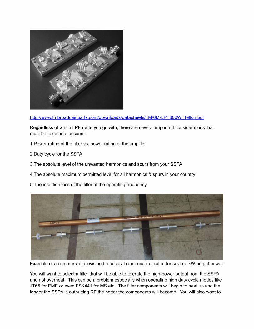
Example of a commercial television broadcast harmonic filter rated for several kW output power.
You will want to select a filter that will be able to tolerate the high-power output from the SSPA and not overheat. This can be a problem especially when operating high duty cycle modes like JT65 for EME or even FSK441 for MS etc. The filter components will begin to heat up and the longer the SSPA is outputting RF the hotter the components will become. You will also want to

look for a filter that has a low Insertion Loss (I.L.) at the operating frequency to help minimize that heat built up.
For example, take two different LPF designs for 6M. Both are identical except one has an I.L. of 0.1dB while the other has an I.L. of 0.3dB. On the outside, the small difference between the two may seem pretty insignificant. However, consider when running 1kW output that the 1st filter will dissipate 23W while the 2nd filter will dissipate 67W! When was the last time you were able to hold a 60W incandescent light bulb with your bare hand?
You will want to make sure the filter you use is rated for the right amount of power and is in a metal enclosure large enough and with proper ventilation to ensure that the components will not be damaged due to over-heating. Remember, the longer the transmitter stays keyed, the hotter all parts will get. If anything, pick a filter or filter components conservatively.
Once your SSPA is up and running and BEFORE you ever put it on the air you should measure its absolute level for all harmonics and spurs. You will want to know the level within 1dB of each harmonic signal your setup is generating. Knowing this will allow you to properly specify how much filtering your LPF must provide in order for your transmissions to be legally compliant.
The easiest way to do this is to set up your rig and SSPA the way you intend to operate it on the air but run the SSPA output into a high power dummy load. Insert a suitable directional coupler (DC) between the SSPA and dummy load. Make sure the DC is calibrated and capable of the power levels in use. The DC will have a sample output port that connects to a spectrum analyzer (SA).
When the rig is keyed up and the SSPA producing 1kW into the dummy load the SA is used to note the level of each spur and harmonic. For example, the SA image below shows the raw harmonic output from a typical Harris 6M SSPA running at 600W.

From this plot we can see that the 2nd harmonic is only 23dB below the fundamental signal operating at 50.250MHz. The 3rd harmonic was 47dB below the fundamental, etc, etc.
Using this data one can then determine how much filtering the LPF must provide in order for the system to be compliant with local regulations. In this particular example a simple homebrew LPF was built and tested with the same setup that was used to capture the image above.
Below is a simple homebrew filter built by W8BYA and its relative frequency response.

Finally, the image below illustrates the final output spectra obtained by using the homebrew filter after the Harris 6M SSPA operating at 1kW output level into a 5 element Yagi. Plots were generated with the SSPA/filter combination operating into a 50 ohm dummy load as well as an actual antenna to ensure that the harmonic levels did not change due to any differences in load impedance.

The plot indicates that all inadvertent spurs and harmonics are at least 60dB below the fundamental signal and is thus compliant with current FCC requirements.

A second harmonic trap is easily built using a short length of coaxial cable and a Tee connector. The line will be a quarter wavelength long at the operating frequency. One end connects to the Tee and the other has the inner and outer conductors connected and soldered. The line length can be calculated as follows. Fine adjustment may be needed to get the notch properly tuned.
L = VF x 2952 / F(MHz)
For RG213 cable, VF=0.66
A 50MHz stub will be 39 inches long from the center of the Tee to the short.
The trap will help reduce potential interference to the FM broadcast band and other even harmonics. As an added bonus, it will ensure the entire antenna system and feedline is held at DC ground potential.
It is very unlikely that any SSPA will meet spectral requirements without external filtering. Without knowing the spectral output it can't be said with certainty whether even the trap is needed. It could be that the third and higher harmonics are clean enough, and 20dB with the trap could do the job. Regardless, you should check for harmonic content and install a proper low pass filter to ensure you are complying with regulations.
Summary
Over the past several years there have been many questions and we have assisted many amateur radio operators get their SSPAs on the air. A short introductory article can not cover all of the questions you may have. Please feel free to contact either Paul N1RJX/ZB0W ([email protected]) or Warren VO1KS ([email protected])
We will happily answer questions to help you decide on which SSPA best suits your needs.
Thanks to W8BYA for putting together the information on output filters at such short notice.
Warren VO1KS
Paul N1RJX