Embed Size (px)
Citation preview

1
Solid-State CMAS Corrosion of an EB-PVD YSZ Coated Turbine
Blade: Zr4+ Partitioning and Phase Evolution
P. Mechnich & W. Braue
This is the authors version of the article published in the
Journal of the American Ceramic Society Vol. 98 (2015) pages 296–302
DOI: 10.1111/jace.13241
© 2015 Wiley Interscience. All rights reserved.
Authors posting; only for personal use, not for redistribution.

2
Solid-state CMAS corrosion of an EB-PVD YSZ coated
turbine blade: Zr4+ partitioning and phase evolution
Peter Mechnich* and Wolfgang Braue
German Aerospace Center (DLR)
Institute of Materials Research
51147 Cologne, Germany
*corresponding author, [email protected]
Abstract
The corrosion of an ex-service 7-YSZ coated high-pressure turbine blade by Si-
undersaturated, Fe-,Ti-rich CMAS (FT-CMAS) was investigated. The constituents of
the FT-CMAS deposit and its synthetic laboratory counterpart are identified by means
of analytical SEM and XRD. FT-CMAS mainly consists of rhönite-, melilite-, and
clinopyroxene-type solid solutions. FT-CMAS reacts with the 7-YSZ thermal barrier
coating (TBC) to a continuous layer of a Ca,Zr-rich garnet phase also known as
kimzeyite. The microstructural analysis indicates that kimzeyite has formed via solid-
state reaction. The formation of kimzeyite was studied in laboratory using YSZ/ FT-
CMAS diffusion couples and powder compacts. Experiments provide strong evidence
that kimzeyite is forming predominantly from YSZ and melilite whereas clinopyroxene
and especially rhönite appear relative stable versus YSZ. The preferred kimzeyite
formation from melilite and YSZ is explained by the availability of 6-fold coordinated
lattice sites for Zr4+ upon melilite decomposition and subsequent garnet
crystallization.

3
Introduction
The ingestion of airborne mineral dust defines a serious threat to aero-engine
performance and service life. The thermal barrier coatings (TBC) suffer from hot-
corrosion associated with the accumulation and infiltration of molten or partially
molten mineral particles. The melt infiltration of TBCs promotes a reduction in
compliance and eventually spallation of the TBC from turbine blades, hence marks a
limitation to the service life of turbine engines. Over the years there has been
considerable effort to assess thermochemical and thermomechanical aspects of TBC
degradation by ingested mineral particles, which is commonly referred to as “CMAS”-
corrosion. A recent comprehensive review of CMAS-related phenomena is given by
Levi et al.1
The blades and vanes of the 1st stage of the high-pressure turbine (HPT) are ideally
suited for similar case studies as their surfaces are directly exposed to the corrosive
combustion gases and impingement of airborne particles. To date only a few field
studies on CMAS-corroded HPT blades with state-of-the-art TBC (Y2O3 stabilized
ZrO2, YSZ) are available in open literature. Such TBC are typically manufactured by
electron-beam vapor deposition (EB-PVD). Vidal-Sétif et al. investigated an ex-
service HPT-blade from a military engine and described the thermochemical
decomposition of the EB-PVD YSZ TBC in a Fe-rich CMAS environment.2 Mercer et
al. used an ex-service blade to study the delamination of CMAS-infiltrated EB-PVD
YSZ TBC. They focused their work on fracture mechanics and derived a “cold shock”
damage mechanism.3
In a previous work we have analysed an ex-service 1st stage HPT airfoil of a Pratt &
Whitney PW 4000 aeroengine with a EB-PVD YSZ TBC fully infiltrated by CaSO4

4
(anhydrite).4 A CMAS deposits with a high CaO-to-SiO2 ratio and significant Fe and
Ti concentrations, was found to trigger the formation of a double corrosion layer
consisting of CaZrO3 and a kimzeyite-type garnet phase (Ca,
Mg)3(Zr,Ti,Fe)2(Al,Fe,Si)3O12. Thus an expanded “FT-CMAS” system was introduced.
In the present work we have investigated an ex-service EB-PVD YSZ coated 1st
stage HPT blade from a Pratt & Whitney PW 2000 aeroengine with a similar “FT-
CMAS” deposit. In contrast to our previous study, the present PW 2000 blade
happened to experience limited CaSO4 infiltration only, thus offering the opportunity
to study CMAS corrosion of YSZ without contribution of CaSO4. Our research is
focusing on phase formation on the pressure surface of the CMAS-corroded HPT
blade. Observations are corroborated by laboratory experiments using EB-PVD 7-
YSZ coatings with artificial CMAS powder deposits.
Experimental Procedure
The ex-service high-pressure turbine blade (HPT) was kindly provided by MTU
Aeroengines Maintenance (Hannover, Germany). Similar aeroengines are employed
for example in Boeing 757 or Boeing C17 type aircrafts. Information on operation
conditions are not available, however a service life of ten thousand hours and beyond
is likely.
The CMAS corrosion scenario was accessed through a combination of scanning
electron microscopy (SEM), energy dispersive spectroscopy (EDS) and X-ray
diffraction (XRD) (see schematic in figure 1). On the basis of the blade’s bulk CMAS
composition a laboratory CMAS powder was synthesized (1250 °C/10 h) from Al-,
Ca-, Mg-, and Fe-nitrates and nanosized SiO2 and TiO2 powders (Merck, Darmstadt,

5
Germany). Individual phases were analysed by EDS spot measurements, re-
synthesized as single phases, and confirmed by means of XRD.
CMAS/7-YSZ diffusion couples were prepared by depositing about 20 mg/cm2 of
laboratory CMAS on top of approximately 250 µm thick EB-PVD coatings (electron-
beam physical vapor deposition, von Ardenne Anlagentechnik, Dresden, Germany).
7 mol-% (4 wt-%) Y2O3-stabilized ZrO2 (TZ-4Y, Tosoh Chemicals, Tokyo, Japan) was
used as reference powder. All heat treatments were performed in a chamber furnace
in air (HTC 03/15, Nabertherm, Bremen, Germany).
SEM analyses were performed in a DSM Ultra 55 scanning electron microscope (Carl
Zeiss NTS, Wetzlar, Germany) equipped with INCA energy-dispersive spectroscopy
(Oxford Instruments, Abingdon, UK). XRD analyses were performed in a D8
Advance diffractometer with CuKα radiation and Lynxeye™ detector (Bruker AXS,
Karlsruhe, Germany). Powders were measured in conventional Bragg-Brentano
geometry while the PW 2000 blade was analyzed in parallel beam geometry using a
Göbel mirror.
Results & Discussion
Corrosion scenario of the PW 2000 HPT blade
The TBC surfaces of the ex-service PW 2000 HPT blade exhibit significant tarnishing
caused by deposited “CMAS” mineral particles. The major part of dark-brown CMAS
is accumulated on the central pressure surface region (fig 2). The significantly lighter
contrasting downstream of the cooling boreholes is probably due to combined effects
of less CMAS deposition and lower surface temperatures. Significant TBC erosion is
mainly observed at the blade tip, where an area of approximately 1 cm2 has spalled

6
off. While the TBC is virtually undamaged at the trailing edge, a small part of the
leading edge has spalled off. A cross-section was performed at the center of the
pressure surface close to the spalled area. The SEM image (Fig.3) shows the typical
columnar microstructure of EB-PVD YSZ. The approximately 50 µm thick CMAS
deposit exhibits a multiphase, fully crystalline microstructure. The chemical
composition of the multiphase overlay was derived via EDS area analysis. The
deposit is mainly composed of classical CMAS-constituents CaO (29.8 mol%), MgO
(11.3 mol%), Al2O3 (11.1 mol%), SiO2 (23.9 mol%). Additionally substantial amounts
of FeO (19.1 mol%), TiO2 (2.1 mol%), and ZrO2 (2.5 mol%) are detected. Note that
the Fe analysis given as FeO is simply for technical reasons and does not imply the
presence of Fe2+. ZrO2 is likely due to dissolution of the YSZ TBC and therefore not
considered as real CMAS-constituent. The same would apply for Y2O3; however the
Y content was generally below the EDS detection limit. The small concentration of Ni
(0.3 mol%) is best attributed to wear of Ni-based alloy of the compressor. In order to
recognize the significant amounts of Fe and Ti, the deposit composition is referred to
as “FT-CMAS”.
The FT-CMAS/YSZ interface is characterized by a few µm thick continuous overlay
and a similar contrasted, approximately 40 µm deep infiltration of the intercolumnar
porosity. Towards the bondcoat an approximately 30 µm thick area with pronounced
open porosity is obvious. In the TBC root zone porosity appears to be filled again.
The infiltration sequence is rationalized by Ca-Kα1, Si-Kα1 and S-Kα1 EDS maps
given as inset in figure 3: Only calcium and sulfur are detected in the TBC root zone,
proving that the lower pore filling is consisting of pure anhydrite (CaSO4). Recently
we observed complete CaSO4-infiltration of intercolumnar TBC porosity of a 1st stage
HPT-blade which can be rationalized as gas-phase transport and subsequent

7
condensation in cooler TBC regions.5 Silicon and calcium are evidently major
constituents of the overlay and the upper pore filling. Due to the limited CaSO4
infiltration it is anticipated that the corrosion zone at the FT-CMAS/YSZ interface has
formed without direct contribution of CaSO4.
Phase paragenesis of the PW 2000 corrosion zone
In analogy to our previous work4 a laboratory FT-CMAS was synthesized at 1250°C,
which is considered a plausible estimate for TBC peak surface temperatures in
engine operation. The qualitative XRD phase analysis revealed that as-synthesized
laboratory FT-CMAS is fully crystalline, consisting of rhönite (RL), melilite (ML), and
clinopyroxene (CL) (Fig. 4 (i); note subscript L for “laboratory”). Due to additional XRD
reflections of tetragonal YSZ (tZ) the interpretation of the XRD profile collected at the
blade’s pressure surface is more difficult. EB-PVD YSZ exhibits strong texture with
weak (101) while (002) and (110) peaks are dominating. Nevertheless melilite (MB)
as well as rhönite (RB) are unambiguously identified, but there is no clear evidence
for clinopyroxene (Fig. 4 (ii); note subscript B for “blade”). The strong XRD peak at
25.5° 2-θ (A) can be assigned to anhydrite CaSO4.
To our best knowledge this is the first report of rhönite in the context of CMAS
corrosion. Rhönite is an accessory rock-forming mineral typically occurring in Fe-rich,
low-silica environments such as basalts.6 Among the most prominent natural
occurrences of rhönite are Ca-,Al-rich inclusions found in the Allende meteorite and
inclusions of augite grains of lunar regolith.7,8 Rhönite has formerly been categorized
as a member of the aenigmatite (aenigmatite: Na2TiFe2+5Si6O20) or the aenigmatite-
rhönite mineral group, but more recently is considered as an equal member of the
highly complex and variable sapphirine group of chain silicates.9-11 The crystal

8
structure analysis of a natural rhönite revealed its triclinic symmetry with an idealized
formula Ca4[(Mg,Fe2+)8Fe3+2Ti2]Al6Si6O40.12 The rhönite structure easily
accommodates various cation species.13 On the other hand, there even exist Fe-free
or Ti-free rhönites, respectively.14,15
Similar synthetic, rhönite-type phases are also technologically relevant: sinter-ores
employed in blast-furnace iron-making are including so-called “silico-ferrite” phases
such as “SFCA” (Si, Fe, Ca, Al) and “SFCAM” (Si, Fe, Ca, Al, Mg) both being
structurally closely related to rhönite.16,17
Melilite (Ca2(MgxAl1-x)(Si1+xAl1-x)O7) refers to tetragonal solid solutions of the end
members akermanite (Ca2MgSi2O7) and gehlenite (Ca3Al2SiO7).18 In Fe-rich
environments, melilite solid solutions can also include the Fe-analogues ferrigehlenite
(Ca3Fe2SiO7) or ferroakermanite (Ca2MgFe2O7).19,20 Previously we have found Fe-
holding melilite as a major constituent of a FT-CMAS deposit of a HPT blade.4
Clinopyroxenes are abundant rock-forming minerals which typically include solid
solutions of end-members such as diopside (CaMgSi2O6) or hedenbergite
(CaFeSi2O6). Al-rich esseneite (CaFe3+AlSiO6) has been described as constituent of
high-temperature metamorphic rocks.21
The morphology of co-existing phases in laboratory FT-CMAS and the corresponding
phases in the corrosion zone of the HPT-blade was studied by SEM and EDS.
Figure 5 shows a polished cross section of laboratory FT-CMAS, while figure 6
shows a close-up of the PW 2000 corrosion zone. Note that both FT-CMAS
microstructures are devoid of glassy phases at triple grain junctions.
The corresponding EDS spot analyses and of solid solution calculations are compiled
in table 1. Note that laboratory phases and blade phases are again marked by “L” and
“B” subscripts, respectively.

9
Large isometric crystals of typically 10 µm and beyond with high relief are identified
as rhönite (RL, RB). From the quantitative EDS analysis (table 1) the chemical
composition of RB is close to that of synthetic RL: while contents of Mg, Al, Si and Ti
are similar the Ca content is higher and the Fe content is lower, respectively. Zr is
generally below detection limit. On the basis of a generalized rhönite structure
(table1) and an allocation of the cations on plausible lattice sites, it is possible to
calculate approximated rhönite-type solid solutions. Note that the assumed
substitutions Ti4+→Fe3+ and Si4+→Al3+ require a slight oxygen deficiency (1.5 oxygen
per unit cell) for achieving charge balance.
Unlike rhönite, both melilites (ML, MB) appear as featureless matrix phase (Figs. 5, 6).
Although the EDS analysis of melilite MB revealed a differing content of Al and Ca,
respectively, all other cation concentrations remain quasi identical (table 1). EDX
quantification and cation allocation allows for approximating both ML and MB as a
solid solution of approximately 50% gehlenite, 10% ferrigehlenite and 40 %
akermanite, respectively. Similar melilites were found upon firing of industrial, Ca-rich
silicate ceramics such as clay bricks.22 Note that both ML and MB are virtually free of
Ti and Zr.
In laboratory FT-CMAS, clinopyroxene CL is forming small, slightly darker contrasted
crystals frequently growing adjacent to rhönite RL (Fig. 5). Again the EDX
quantification and cation allocation in a generalized structure were employed for an
approximation of a charge-balanced clinopyroxene stoichiometry. Note that the
clinopyroxene EDS analyses in table 1 requires cation position T[4] being fully
occupied by Si and Al and position A[8] fully occupied by Ca, respectively. Therefore
Mg, Fe, and minor Ti, Zr were allocated to position B[6] only. A simplified model solid
solution for CL would consist of 60% esseneite, 30% diopside and 10 % hedenbergite
(table 1). A rather similar clinopyroxene having a composition of

10
Ca0.96(Al0.20Fe0.35Mg0.44)(Al0.20Fe0.08Si0.70)2O6.12 has been described in literature.23 The
PW 2000 blade exhibits a different scenario: interestingly CB seems to be is
accumulated in a layer close to the TBC interface (fig 5). Compared to CL CB holds
approximately 50% less Fe and 25 % more Al and Mg, respectively (table 1).
In contrast to XRD analysis (Fig. 4) SEM of the laboratory FT-CMAS analysis reveals
an additional crystalline phase “TL” appearing as light-gray contrasted grains with
sizes typically below 5 µm (Fig. 5). On the basis of EDS spot analysis and
subsequent single synthesis phase “TL” could be identified as a Ti-rich, garnet-type
solid solution (table 1). Ti-rich garnets, such as melanites and schorlomites, are also
referred to as Ti-andradites with the empirical formula Ca3Fe2(Si0.5Ti0.5)3O12.24 TL is
easily approximated by a 50:50 mol% solid solution of Ti-andradite and grossular
(Ca3Al2Si3O12). Remarkably similar garnets have been reported elsewhere.25 The
absence of garnet reflections in the XRD profile (Fig. 4) is apparently due to peak
overlap: for example, the characteristic XRD reflections of Ti-andradite (ICDD PDF-2;
#78-0319)26 220 (d=0.423 nm), 400 (d=0.306 nm) and 422 (d=0.273 nm) coincide
with strong melilite XRD-reflections 101 (d=0.422 nm), 201 (d=0.307 nm) and 211
(d=0.285 nm), respectively.
The PW 2000 blade exhibits a reaction layer between the EB-PVD YSZ coating and
the crystalline FT-CMAS overlay (Fig. 6). EDS analysis as well as single-phase
synthesis unambiguously prove that newly formed KB1 is a Zr-rich garnet-type solid
solution. Such garnets are commonly referred to as kimzeyite with an empirical
formula Ca3(Zr,Ti,Fe,)2(Al,Fe,Si)3O12.27,28 The approximation of the KB1 solid solution
(table 1) required an allocation of Fe3+ to tetrahedral T sites, resulting in an almost
equivalent distribution of Fe3+ on octahedral B and tetrahedral T, respectively.
An additional phase is appearing as light-gray contrasted grains having a size 0.5-1
µm and is typically growing adjacent to the clinopyroxene (CB) layer or rhönite (RB)

11
(white arrows in Fig. 6). The label KB2 is pointing out that this phase could be
identified as a second kind of kimzeyite: KB2 is holding all available cations and the
approximation of a charge balanced garnet stoichiometry is viable. A significant
feature of KB2, however, is a much lower Zr content (5.6%) compared to KB1 (14%).
Moreover, KB2 exhibits s significant higher content of Al, therefore no Fe3+ had to be
allocated to the T site (table 1). Figure 6 displays some monoclinic ZrO2 (mZ) located
at TBC column tips. Note that surrounding TBC pores are partially unfilled and mZ
grains are in contact with kimzeyite KB1. The formation of mZ may be triggered by a
thin, glassy grain boundary film. However, spherulitic, (Ca-bearing) ZrO2 grains being
characteristic for YSZ dissolution and subsequent re-precipitation in excess siliceous
liquid phase are not a characteristic microstructural feature.
Laboratory duplication of the PW 2000 CMAS corrosion scenario
The phase formation and microstructural evolution of the PW 2000 blade were
duplicated by depositing laboratory FT-CMAS powder on an EB-PVD 7-YSZ coated
alumina coupon and subsequent annealing at 1250 °C for 10 hrs. Again, the
temperature of 1250°C was selected in analogy to our previous work.4 The SEM
cross section at the interface (fig. 7) reveals the formation of a pronounced reaction
zone fully enveloping YSZ column tips as well infiltration of intercolumnar TBC
porosity, both having a striking similarity with the PW 2000 scenario. The overlay and
the pore fillings unequivocally consist of kimzeyite, referred as to KL in the following.
The average EDS analysis of KL reveals a good agreement with KB1 of the PW 2000
blade (table 1). On the other hand, there is only partial “wetting” of the TBC surface
by FT-CMAS, at first glance conflicting to the continuous KL overlay. Moreover, there

12
are almost no melilite (M) and clinopyroxene (C) grains co-existing with KL whereas
rhönite (R) grains adjacent to KL exhibit notable large grain sizes.
The phase evolution of the laboratory diffusion couple was corroborated by
supplementary annealing experiments using 80/20 wt% powder mixtures of YSZ (TZ-
4Y) and synthetic RL CL, and ML, respectively. The XRD profile (i) in figure 8 reveals
that RL and tetragonal ZrO2 (tZ) still co-exist after one hour at 1250°C. No additional
XRD reflections can be detected. The CL/TZ-4Y powder mixture (Fig. 8, profile ii)
shows weak, very broad XRD peaks at 29°, 32.5° and 55.5° 2-θ which may be
assigned to kimzeyite (K). Note that the tZ peak doublets (112)/(200) at 50° 2-θ and
(102)/(211) at 60° 2-θ indicate a significant evolution of tZ, i.e. the tetragonality of
ZrO2 as expressed by the doublets’ peak distances has seemingly decreased.
The behavior of the ML/TZ-4Y powder mixture is evident: new kimzeyite XRD
reflections (K) appear (Fig.8, profile iii). In contrast to the RL and CL mixtures, ZrO2 is
now existing as cubic polymorph (cZ): the tZ peak doublets (112)/(200) at 50° 2-θ
and (102)/(211) at 60° 2-θ have disappeared at the expense of the (220) and (311)
single peaks of cubic cZ. The tetragonal-to-cubic transformation of TZ-4Y may either
be explained by incorporation of additional stabilizer such as Ca2+ or the relative
enrichment of Y3+ caused by Zr4+ depletion due to formation of kimzeyite.
At first glance there is no evidence for the relative preference for the reaction of YSZ
and melilite to kimzeyite, since rhönite and clinopyroxene offer the same cations, in
particular sufficient Ca2+. Accessing this observation via thermodynamic analysis or
simulation of the eight-component system (Ca-Mg-Al-Si-Fe-Ti-Zr-O) is considered not
very promising since all relevant phases exhibit extensive solid solubility.
Alternatively, the preferred oxygen coordination of present cations and their relative
concentrations can help to rationalize the specific reactivity observed. In particular

13
the behavior of Zr4+, typically occupying the octahedrally coordinated B-site of garnet
structures27, is considered a key to the present corrosion scenario. The total number
of cation sites and their respective oxygen coordination number [CN] of the relevant
crystal structures are compiled in table 2. A premise for the following considerations
is the stabilization of Zr4+ solely on octahedrally coordinated sites (“[6]-sites”).
The rhönite structure comprises a total of twelve [6]-sites, in the present case
occupied by Fe2+, Fe3+, Ti4+, and Al3+. Consequently, diffusion of Zr4+ into the rhönite
structure is hindered, as supported by the low-to-zero Zr-content of RB (table 1). A
fictional kimzeyite formation via rhönite decomposition implicates that all ([7]-
coordinated) Ca2+ of rhönite is occupying the A[8]-sites of the newly formed garnet.
“Normalizing” the numbers of the rhönite [8]-, [6]-, and [4]-sites to three garnet A[8]-
sites yields nine [6]-sites. Only two of them need to be re-assigned to garnet B[6]-
sites, i.e. seven surplus [6]-sites remain. By analogy six [4]-cations of rhönite would
translate to three tetrahedral T[4]-sites with three surplus [4]-sites remaining. If
additional Zr4+ is exclusively occupying [6]-sites, it would have to compete for garnet
B[6]-sites with an enormous excess of Fe2+,3+,Ti4+. Following this concept, the relative
high concentration of [6]-cations (Fe2+,3+, Ti4+) in rhönite represents a too high barrier
for the formation of a Zr-bearing garnet structure, in good agreement with the lack of
kimzeyite in the RL/TZ-4Y powder mixture.
A similar, fictional transformation of clinopyroxene to garnet would yield one extra [6]-
site, and three extra [4]-sites, respectively. In this case only one extra [6]-cation
would have to compete with Zr4+, consequently the barrier for kimzeyite formation
should be lower than for the rhönite case. Indeed, the only minor kimzeyite formation
in the CL/TZ-4Y powder mixture (Fig.8) supports this hypothesis.
A completely different situation exists in case of melilite: the structure includes two
[8]-sites and two [4]-sites, but no [6]-sites. A fictional conversion of the “normalized”

14
melilite structure to a kimzeyite-type garnet is easily achieved by re-allocation of 1.5
cations, evidently Al3+,Fe3+ from T[4]-sites to newly formed B[6]-sites (table 2, i).
Subsequently filling the 0.5 B[6] sites by Zr4+ (table 2,ii) results in the total reaction
1.5 Melilite + 0.5 Zr[6]O2 → Kimzeyite
This concept may explain the enhanced formation of kimzeyite in the ML/TZ-4Y
powder mixture. The two model reactions based upon laboratory melilite ML and pure
ZrO2 are supporting the plausibility of this concept (table 2). Note that the allocation
of Mg2+ on A[8] gives rise to a higher Zr-concentration in the garnet, quite similar to
the experimental observations.
From the supplementary annealing experiments it is concluded that the continuous
kimzeyite layer enveloping the TBC column tips has formed preferentially at the
expense of melilite while large rhönite grains represent residues of this reaction. In
contrast to the PW 2000 blade (see Fig. 7) the laboratory diffusion couple does not
exhibit the formation of a clinopyroxene layer separating kimzeyite and melilite. The
stability considerations, however, do not rule out such a (Zr-saturated) clinopyroxene
layer: even if residual rhönite is stable with respect to kimzeyite, it may react with
excess melilite to clinopyroxene in the long term.
A further microstructural feature of the laboratory FT-CMAS/EBPVD 7YSZ diffusion
couple is presented in figure 9 (close-up of the boxed region in figure 7). In addition
to major melilite (M) and rhönite (R), the FT-CMAS overlay is holding a large number
of newly formed small, Ti- and Zr-rich grains frequently exhibiting a core/rim element
contrast. The inset represents an EDS line scan (normalized to Ti and Zr) across two
adjacent grains (dashed arrow). The line scan proves that grains are exhibiting a Ti-
rich core and a Zr-rich rim, respectively. Ti-rich cores may be assigned to initially
present TL or TL-nuclei, rims have evidently formed by accumulation of Zr diffusing
out of EB-PVD YSZ. Therefore these grains may be regarded as (early-stage)

15
analogues of small, isolated KB2 kimzeyites and may explain their occurrence distant
from the FT-CMAS/YSZ interface of the PW 2000 blade (Fig. 6).
General aspects of the PW 2000 CMAS corrosion scenario
Unlike SiO2-saturated CMAS-type corrosion scenarios, such as standard laboratory
CMAS29, neither the ex-service HPT blade nor the laboratory diffusion couples show
evidence for TBC dissolution and re-precipitation of Y-depleted and Ca-containing
(monoclinic) YSZ spherules. It is anticipated that YSZ dissolution/ re-precipitation
requires a substantial amount of a siliceous liquid phase. The ex-service blade as
well as laboratory experiments indicate that in SiO2-undersaturated environments
YSZ decomposition is occurring essentially via solid state reactions. The
microstructural analyses prove that the reaction zone between YSZ TBC and FT-
CMAS deposit is consisting of kimzeyite-type garnet KB1 which evidently is forming
only in environments providing sufficient Ca and Fe. A noteworthy feature, however,
is the approximately 40 µm deep infiltration of the intercolumnar porosity by KB1 since
a significant temperature gradient is expected across the TBC thickness. The
diffusion of species along EB-PVD YSZ columns is obviously high enough to enable
long-term stabilization of kimzeyite even if temperatures remain well below the
1250°C estimate at the HPT blade pressure surface. A lower temperature limit of
1150°C seems plausible.
The present study is in good agreement with our previous work where a double layer
consisting of a similar kimzeyite garnet and CaZrO3 was found as CMAS corrosion
scenario of an ex-service 7-YSZ coated, fully CaSO4-infiltrated PW 4000-type HPT
blade3, emphasizing the general significance of Ca,Zr,Fe-garnets for the corrosion of
7-YSZ TBCs. In the present PW 2000 blade, however, we find no formation of
CaZrO3. This is confirming our assumption that CaZrO3 is forming directly from

16
infiltrated CaSO4 and YSZ above estimated 1100°C. In the present case the CaSO4
pore-filling is limited to the TBC root zone and obviously did not reach the necessary
temperature level for CaZrO3 formation. The CaSO4 infiltration at the root zone of the
present TBC emphasizes the gas-phase condensation concept5 since there is no
plausibility that any “CaSO4-liquid” would be able to migrate across the entire TBC
thickness leaving behind a zone of open porosity. Instead, one would expect rapid
“freezing” of such a liquid in the temperature gradient across the TBC thickness. The
CaSO4 infiltration of intercolumnuar TBC porosity is considered a global effect in
turbine operation; however the underlying mechanism is still not worked out in detail
and calls for more R&D efforts in future.
The large spalled TBC area is located at the center of the HPT blade where
presumably particle accumulation as well as thermal load is maximal. At this point,
however, the impact of “solid-state” CMAS-recession on TBC lifetime is difficult to
estimate. Isothermal and thermal gradient cyclic testing of laboratory specimen will
provide data comparable to results obtained for “classical” TBC corrosion induced by
CMAS-melt infiltration. Physical data such as specific thermal expansion of relevant
solid solutions (kimzeyite, rhönite, melilite) are required for the evaluation of
mechanical stresses. The manufacturing of laboratory specimen, however, is
considered difficult: the present study shows that simple deposition and annealing of
FT-CMAS powders does not produce a conformal and dense TBC overlay even at
1250 °C. Advanced deposition methods, such as thermal spraying of FT-CMAS
powders, may enable the duplication of real corrosion scenarios.

17
Conclusions
The corrosion of the investigated ex-service PW 2000 HPT blade is induced by a
silica-undersaturated CMAS deposit including Fe and Ti as major constituents (FT-
CMAS). FT-CMAS constituents are crystalline solid solutions such as rhönite,
melilite, and clinopyroxene. The present corrosion scenario exhibits no evidence for
FT-CMAS melting and YSZ dissolution/re-precipitation. Instead FT-CMAS deposits
and YSZ TBC react to kimzeyite-type Ca,Zr,Fe-garnets in the solid state. Kimzeyite
forms a continuous layer enveloping TBC column tips, however is also crystallizing in
the topmost TBC pores. Kimzeyite forms most easily from melilite and YSZ, whereas
present rhönite appears most stable versus YSZ. The preferred reaction of melilite is
attributed to its significant lower concentration of transition-metal cations competing
with Zr4+ for octahedrally coordinated garnet sites. The results emphasize that
CMAS-corrosion of YSZ is possible even in absence of siliceous liquid phases and is
considered as much relevant as SiO2-saturated CMAS-corrosion.
Acknowledgement
The support by A. Ebach-Stahl and P. Watermeyer (DLR) for the preparation of the
HPT blade is gratefully acknowledged.

18
References
1 C. G. Levi , J. W. Hutchinson , M.-H. Vidal-Sétif, and C. A. Johnson, “Environmental
degradation of thermal barrier coatings by molten deposits”, MRS Bull. 37, 932-941
(2012)
2 M.-H. Vidal-Setif, N. Chellah, C. Rio, C. Sanchez, and O. Lavigne, “Calcium–
magnesium–alumino-silicate (CMAS) degradation of EB-PVD thermal barrier
coatings: Characterization of CMAS damage on ex-service high pressure blade
TBCs”, Surf. Coat. Techn. 208, 39-45 (2012)
3C. Mercer, S. Faulhaber, A.G. Evans, and R. Darolia, ”A delamination mechanism
for thermal barrier coatings subject to calcium–magnesium–alumino-silicate (CMAS)
infiltration”, Acta Mater. 53, 1029–1039 (2005)
4 W. Braue, and P. Mechnich, “Recession of an EB-PVD YSZ Coated Turbine Blade
by CaSO4 and Fe, Ti-Rich CMAS-Type Deposits”, J. Am. Ceram. Soc. 94[12] 4483-
4489 (2011)
5 W. Braue, P. Mechnich, and P. W. M. Peters, “The CaSO4 phase in fully infiltrated
electron-beam physical vapour deposited yttria stabilized zirconia top coats from
engine hardware”, Mat. at High Temp. 28[4], 315-323 (2011)
6 R. Grapes, and J. Keller, “Fe2+-dominant rhönite in undersaturated
alkaline basaltic rocks, Kaiserstuhl volcanic complex, Upper Rhine Graben,
SW Germany”, Eur. J. Mineral. 22[2], 285-292 (2010)
7 L. H. Fuchs, “The mineralogy of a rhönite-bearing calcium aluminium rich inclusion
in the Allende meteorite, Meteoritics 13[1], 73-88 (1978)
8 A. H. Treiman, “Rhönite in Luna 24 pyroxenes: First find from the Moon, and
implications for volatiles in planetary magmas”, Am. Min. 93, 488–491(2008)

19
9 B. B. Jensen, “Solid solution among members of the Aenigmatite group”, Min. Mag.
60 982-986 (1996)
10 T. Kunzmann, “The aenigmatite-rhonite mineral group”, Eur. J. Min. 11 [4] 743-756
(2004)
11 E. S. Grew, U. Halenius, M. Pasero, and J. Barbier, “Recommended nomenclature
for the sapphirine and surinamite groups (sapphirine supergroup)”, Min. Mag. 72(4),
839–876 (2008)
12 K. Walenka, “Zur Kristallographie des Rhönits”, Z. Krist 130, 214-230 (1969) (in
german; abstract also in english)
13 A. D. Johnston, and J. H. Stout, “Compositional variation in naturally occurring
rhönite”, Am. Min. 70, 1211-1216 (1985)
14 M. A. Cosca, R. R. Rouse, and E. J. Essene, “Dorrite [Ca2(Mg2Fe3+4)(Al4Si2)O20], a
new member of the aenigmatite group from a pyrometamorphic melt-rock”, Am. Min.
73, 1440-1448 (1988)
15 E. Bonaccorsi, S. Merlino, and M. Pasero, “Rhonite: structural and microstructural
features, crystal chemistry and polysomatic relationships”, Eur. J. Min. 2, 203-218
(1990)
16 N. A. S. Webster, M. I. Pownceby, I. C. Madsen, and J. A. Kimpton, “Silico-ferrite of
Calcium and Aluminum (SFCA) Iron Ore Sinter Bonding Phases: New Insights into
Their Formation During Heating and Cooling”, Met. and Mat. Trans. B 43, 1344-1357
(2012)
17 K Sugiyama, A. Monkawa, and T. Sugiyama, “Crystal structure of the SFCAM
phase Ca2(CaFeMgAl)6(FeAlSi)6O20”, ISIJ International 45[4], 560-568 (2005)
18 I. P. Swainson, M. T. Dove, W. W. Schmahl, and A. Putnis, “Neutron Diffraction
Study of the Akermanite-Gehlenite Solid Solution Series”, Phys. Chem. Min. 19, 185-
195 (1992)

20
19 V. Zacek, R. Skala, M. Chlupacova, and Z. Dvorak, “Ca-Fe3+-rich, Si-
undersaturated buchite from Zelenky, North-Bohemian Brown Coal Basin, Czech
Republic”, Eur. J. Mineral.17, 623-633 (2005)
20 F. F. Foit Jr, R. L. Hooper, and P. E. Rosenberg, “An unusual pyroxene, melilite,
and iron oxide mineral assemblage in a coal-fire buchite from Buffalo, Wyoming”, Am.
Min. 72, 137-147 (1987)
21 M. A. Cosca, and D. R. Peacor, “Chemistry and structure of esseneite
(CaFe3+AlSiO6), a new pyroxene produced by pyrometamorphism” Am. Min. 72, 148-
156 (1987)
22 M. Dondi, G. Ercolani, B. Fabbri, and M. Marsigli, “Chemical Composition of
Melilite Formed during the Firing of Carbonate-Rich and Iron-Containing Ceramic
Bodies”, J. Am. Ceram. Soc. 82[2], 465-68 (1999)
23 Y. K. Kabalov, O. Oeckler, E. V. Sokolova, A. B. Mironov, and B. V. Chesnokov,
“Subsilicic ferrian aluminian diopside from the Chelyabinsk coal basin (Southern
Urals) - an unusual clinopyroxene”, Eur. J. Min. 9, 617 -621 (1997)
24 F. E. Huggins, D. Virgo, and H. G. Huckenholz, “Titanium-containing silicate
garnets. II. The crystal chemistry of melanites and schorlomites”, Am. Min. 62, 646-
665 (1977)
25 A. Kühberger, T. Fehr, H. G. Huckenholz, and G. Amthauer, ”Crystal Chemistry of
a Natural Schorlomite and Ti-Andradites Synthesized at Different Oxygen
Fugacities”, Phys. Chem. Min. 16 734-40 (1989)
26 Powder Diffraction File, International Center for Diffraction Data (ICDD), Newtown
Square, PA.
27 J. Ito and C. Frondel, “Synthetic Zirconium and Titanium Garnets”, Am. Min. 52,
773-781 (1967)

21
28 R. Munno, G. Rossi, and C.Tadini, “Crystal chemistry of kimzeyite from Stromboli,
Aeolian Islands, Italy”, Am. Min. 65, 188-191(1980)
29 S. Krämer, J. Yang, C.G. Levi, and C.A.J. Johnson, “Thermochemical Interaction
of Thermal Barrier Coatings with Molten CaO-MgO-Al2O3-SiO2 (CMAS) Deposits”, J.
Am. Ceram. Soc., 89[10] 3167-75 (2006)
Figure Captions
Fig. 1 : Schematic of the experimental procedure adopted in this study
Fig. 2 :. Pressure surface of the ex-service 1st stage HPT blade of a PW 2000
aeroengine exhibiting CMAS particle contamination and partial TBC spallation
Fig. 3 : Polished cross-section of EB-PVD YSZ coating with CMAS overlay (SE
image) showing a continuous reaction layer at the interface. The inserted Ca and Si
EDS maps indicate infiltration of upper intercolumnar gaps by a siliceous phase
whereas Ca and S EDS maps indicate CaSO4-infiltration of the TBC root zone.
Fig. 4 : (i) XRD profile of laboratory FT-CMAS exibiting melilite (ML), rhönite (RL) and
clinopyroxene (CL) solid solutions. (ii) XRD profile collected from the corroded HPT
blade. Beside textured tetragonal YSZ (tZ) from the TBC, melilite (MB) as well as
rhönite (RB) are clearly detected. The peak (A) can be assigned to anhydrite. (Note
subscripts L for laboratory and B for blade)

22
Fig. 5 : Polished cross-section (SE image) of laboratory FT-CMAS (1250 °C/ 10 h)
exhibiting the specific morphologies of rhönite (RL), melilite (ML), and clinopyroxene
(CL). A light-contrasted, small-grained phase (TL) is identified as Ti-rich garnet.
Fig. 6 : Polished cross-section of the EB-PVD coated HPT blade (SE image)
exhibiting the specific morphologies of rhönite (RB) and melilite (MB). Clinopyroxene
(CB) is accumulated in a layer adjacent to the reaction zone consisting of kimzeyite-
type garnet (KB1). Small grains marked by arrows are also identified as kimzeyite
(KB2). Note the infiltration of intercolumnar gaps by KB1. Partial YSZ destabilization to
monoclinic ZrO2 (m-Z) is observed at the blunted column tips.
Fig. 7 : Phase assemblage (SE contrast) from the EB-PVD YSZ/synthetic FT-CMAS
diffusion couple experiment upon annealing at 1250 °C/10 h. Phases include melilite
(ML), rhönite (RL) and newly formed kimzeyite (KL). See Fig. 9 for close-up of boxed
region.
Fig. 8 : XRD profiles collected from 80/20 wt-% powder mixtures annealed at 1250
°C/ 1h: (i) RL/ TZ-Y4; (ii) CL/ TZ-Y4 ; (iii) ML/TZ-Y4. Note relative stability of rhönite RL
and preferred kimzeyite formation from YSZ and melilite ML.
Fig. 9 : Boxed region from Fig. 7: Small precipitates frequently exhibit a pronounced
core/rim structure. The normalized EDS line scan across two zoned microcrystals
(dashed arrow) reveals Ti-rich cores and Zr-rich rims, respectively.

Fig.1
Fig.2
Fig. 3

Fig. 4
Fig. 5
Fig.6
Fig. 7
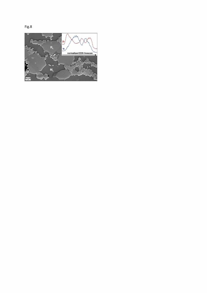
Fig.8

Table 1: Solid solutions in laboratory samples and in the CMAS-deposit of the PW 2000 HPT-blade
Rhönite (RL; RB)
empirical formula14
generalized rhönite structure
Ca4[(Mg,Fe2+)8Fe3+2Ti2]Al6Si6O40
A[7]4[B[6]
8C[6]2D[6]
2]E[4]6F[4]
6O40
average EDS analysis [cation mol-%] Mg Al Si Ca Ti Fe Zr
laboratory FT-CMAS : RL 14.5 23.8 14.4 15.4 2.3 29.5 -
PW 2000 blade : RB 14.6 25.0 15.7 18.1 1.8 24.8 0.0
cation allocation in generalized structure B E F A;B D B;C D;E
-
approximated rhönitess RL Ca4[(Mg0.5Fe2+
0.5)8(Fe2(Fe1.25Ti0.75)] (Al0.8Fe0.2)6(Al0.33Si0.67)6O38.5
approximated rhönitess RB Ca4[(Mg0.5Fe2+0.375Ca0.125)8(Fe2(Fe0.75Ti0.25)]
(Al0.917Fe0.083)6(Al0.25Si0.75)6O38.5
Melilite (ML ; MB)
empirical formula17
generalized melilite structure
Ca2(MgxAl1-x)(Si1+xAl1-x)O7
A[8]2B[4]T[4]
2O7
average EDS analysis [cation mol-%] Mg Al Si Ca Ti Fe Zr
laboratory FT-CMAS : ML 7.3 21.9 28.1 38.6 0.0 4.1 -
PW 2000 blade : MB 7.1 19.7 27.2 43.0 0.0 3.0 0.0
cation allocation in generalized structure B T;B T A - B -
approximated melilitess ML Ca2(Mg0.4Al0.4Fe0.2)(Si1.4Al0.6)O7
approximated melilitess MB Ca2(Mg0.35Al0.48Fe0.17)(Al0.65Si1.35)O7
Clinopyroxene (CL ; CB)
empirical formula22
generalized clinopyroxene structure
Ca(Mg,Fe3+)[(Si,Al)2O6]
A[8]B[6]T[4]2O6
average EDS analysis [cation mol-%] Mg Al Si Ca Ti Fe Zr
laboratory FT-CMAS : CL 7.8 15.5 29.4 24.4 2.6 20.3 -
PW 2000 blade : CB 9.5 21.9 30.5 24.5 1.6 9.5 2.5
cation allocation in generalized structure B T;B T A B B B
approximated clinopyroxeness CL Ca(Mg0.3Fe0.6Ti0.1)(Al0.3Fe0.1Si0.6)2O6
approximated clinopyroxeness CB Ca(Mg0.41Fe0.41Ti0.07Zr0.11)(Al0.42Si0.58)2O6

Ti-Garnet / Kimzeyite (TL / KB1, KB2, KL)
empirical formula24,27
generalized garnet structure
Ca3(Al,Fe,Ti)2(Al,Si,Ti)3O12 / Ca3(Fe,Ti,Zr)2(Al,Fe,Si)3O12
A[8]3B[6]
2T[4]3O12
average EDS analysis [cation mol-%] Mg Al Si Ca Ti Fe Zr
laboratory FT-CMAS : TL 3.6 12.9 30.3 31.9 8.7 12.6 -
PW 2000 blade : KB1 2.9 8.9 22.7 33.4 4.0 14.1 14.0
PW 2000 blade : KB2 5.5 13.7 24.6 31.2 4.8 14.6 5.6
laboratory FT-CMAS/EB-YSZ diffusion couple : KL 1.4 10.1 17.0 35.7 2.5 15.2 18.1
cation allocation in generalized structure A T;B T A B B;T B
approximated Ti-Garnetss TL (Ca0.90Mg0.10)3(Al0.2Fe0.47Ti0.33)2(Al0.20Si0.80)3O12
approximated Kimzeyitess KB1 (Ca0.92Mg0.08)3(Fe0.28Ti0.16Zr0.56)2(Al0.23Fe0.18Si0.59)3O12
approximated Kimzeyitess KB2 (Ca0.85Mg0.15)3(Fe0.59Ti0.19Zr0.22)2(Al0.35Si0.65)3O12
approximated Kimzeyitess KL (Ca0.96Mg0.04)3(Fe0.18Ti0.10Zr0.72)2(Al0.27Fe0.28Si0.45)3O12
[8] [7] [6] [4] oxygen coordination numbers of cation sites

Table 2 : Crystal chemistry of relevant phases from PW 2000 blade and laboratory experiments
Crystal structure total cation sites [CN] normalized to 3 [8]-sites
[8] [6] [4] [8] [6] [4]
Garnet24,27 3 2 3 3 2 3
Rhönite14 4* 12 12 3 2+7 3+6
Clinopyroxene22 1 1 2 3 2+1 3+3
Melilite17 2 0 3 3 0 3+1.5
Melilite-to-Garnet “conversion” scheme (i) 1.5•[4] → 1.5•[6]
(ii) 1.5•[6] + 0.5•[6] → 2•[6]
3
3
1.5
2
3
3
Proposed reaction 1.5 Melilite + 0.5 Zr[6]O2 → Kimzeyite
model #1: ML**+ ZrO2 → Kimzeyite;
total Mg2+ allocated to site B[6]
1.5 Ca2(Mg0.4Al0.4Fe0.2)(Al0.6Si1.4)O7 + 0.6 ZrO2***
→ Ca3(Mg0.3Al0.3Fe0.1Zr0.3)2(Al0.3Si0.7)O12
model #2 : ML**+ ZrO2 → Kimzeyite;
total Mg2+ allocated to site A[8]
1.25 Ca2(Mg0.4Al0.4Fe0.2)(Al0.6Si1.4)O7 + 1.25 ZrO2***
→ (Ca0.833Mg0.167)3(Al0.25Fe0.125Zr0.625)2(Al0.25Si0.75)O12
*coordination number CN=[7] ; **laboratory melilite (see also table 1) ; ***Y2O3 stabilizer not considered