Embed Size (px)
Citation preview
SoLID baffle update
Zhiwen Zhao2013/04/02
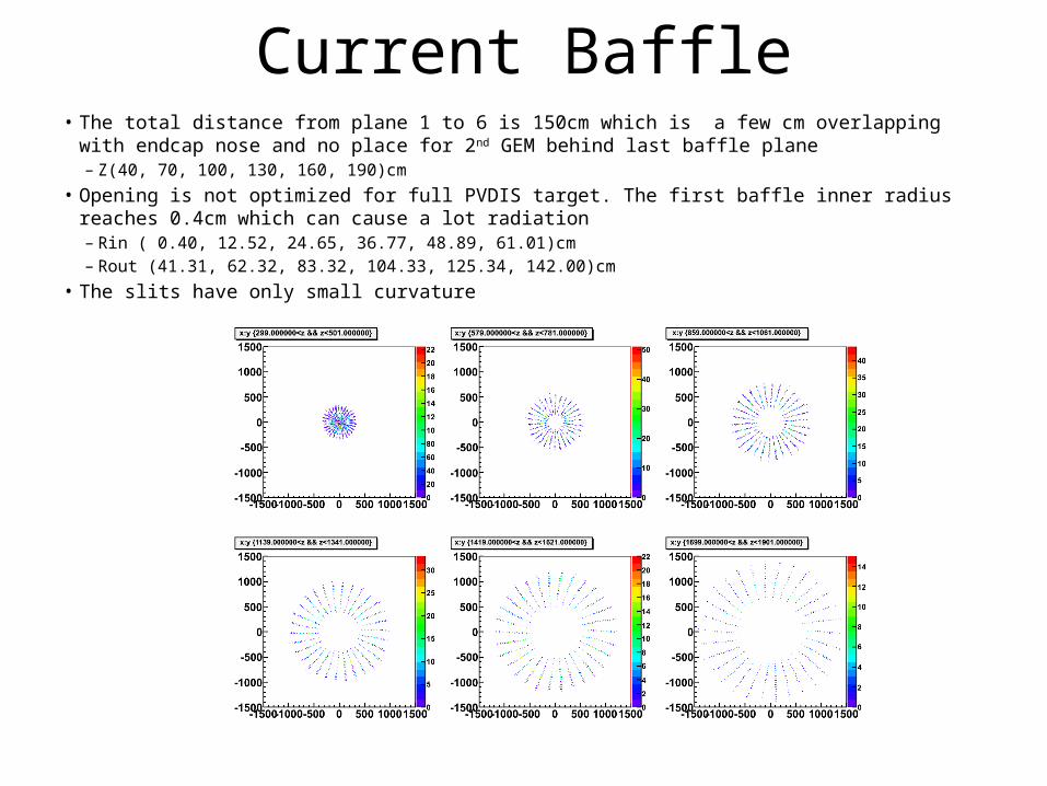
Current Baffle• The total distance from plane 1 to 6 is 150cm which is a few cm overlapping with endcap nose and no place
for 2nd GEM behind last baffle plane– Z(40, 70, 100, 130, 160, 190)cm
• Opening is not optimized for full PVDIS target. The first baffle inner radius reaches 0.4cm which can cause a lot radiation– Rin ( 0.40, 12.52, 24.65, 36.77, 48.89, 61.01)cm– Rout (41.31, 62.32, 83.32, 104.33, 125.34, 142.00)cm
• The slits have only small curvature

Current Baffle (neg acceptance)
• 45% - 10% along P
P Theta
P:Theta x
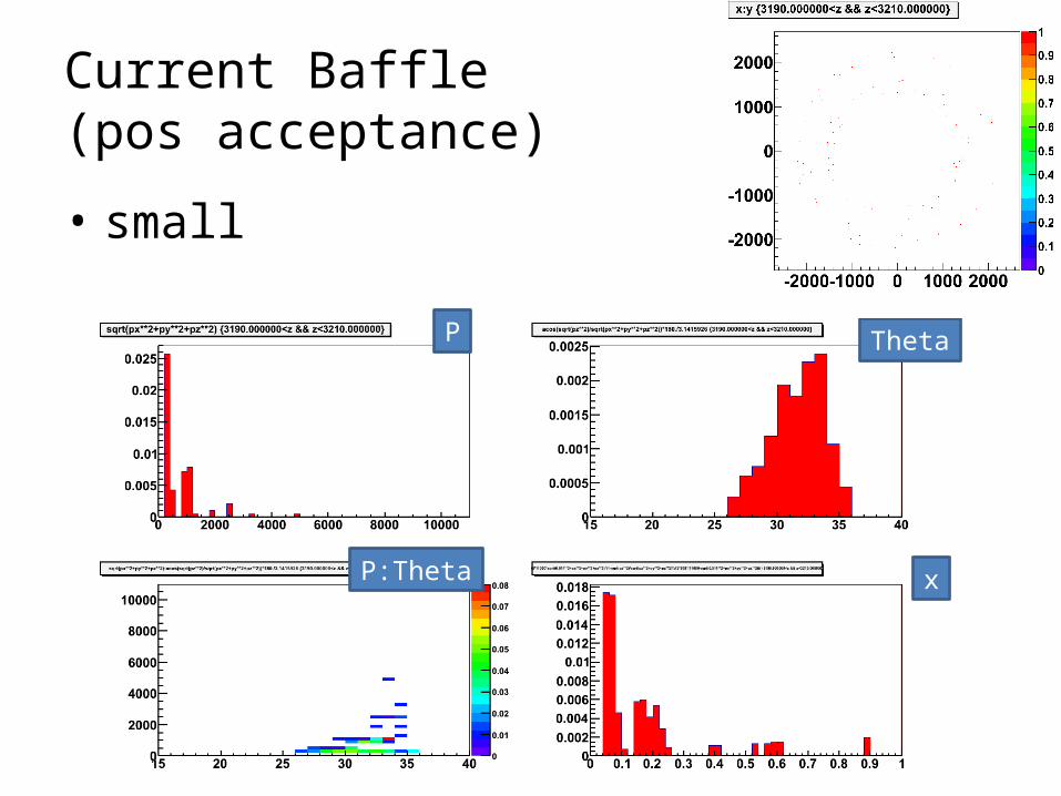
Current Baffle(pos acceptance)
• small
P Theta
P:Theta x

Current Baffle(neutral acceptance)
• ~0.5% along P
P Theta
P:Theta x

Current Baffle(neutral acceptance)
• Rotating last baffle by +1 or -1 degree increase neutral acceptance to 1% or 3%
-1 deg
original
+1 deg

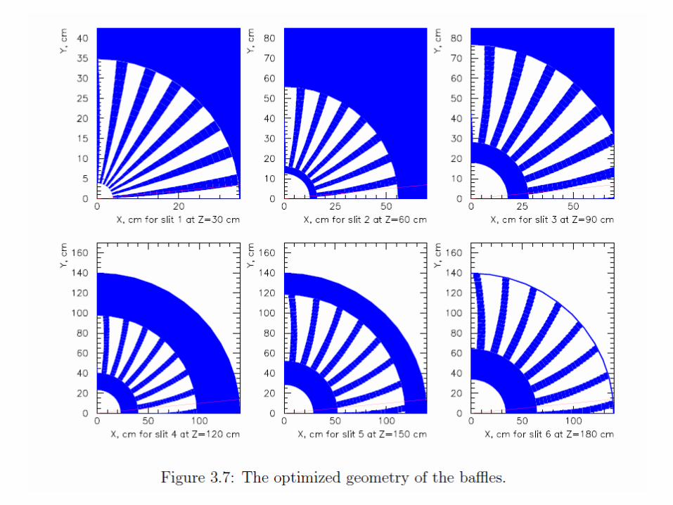
New Idea• Still 30 sectors with each sector covering 12 deg• In each sector, each slit covers 2 deg, 6 slits shift 2 deg from each
other• all slits are straight• Line of sight from Z axis is blocked completely

New Idea• Still each plate is 9cm thick• line of sight is open for vertex off Z axis. Increasing slit size will help blocking it. Assume vertex is with
2mmD and set slit width at 2.3 deg• Fit within the current setup without overlap
– Z (40, 68, 96, 124, 152, 180) cm• Opening in R is optimized for acceptance from 21 to 36 deg for full 40cm long target with center at 10cm
– Rin (3.8,14.5,25.3,36.0,46.8,57.5)cm– Rout (36.4,56.7,77.1,97.4,117.8,138.1)cm

New Baffle (neg acceptance)• 70% - 10% along P
– Larger than current baffle– PVDIS of FOM should be better also– Don’t have cut off at 2GeV
P Theta
P:Theta x

New Baffle(pos acceptance)
• 40% - 0% along P– much more than current baffle
P Theta
P:Theta x

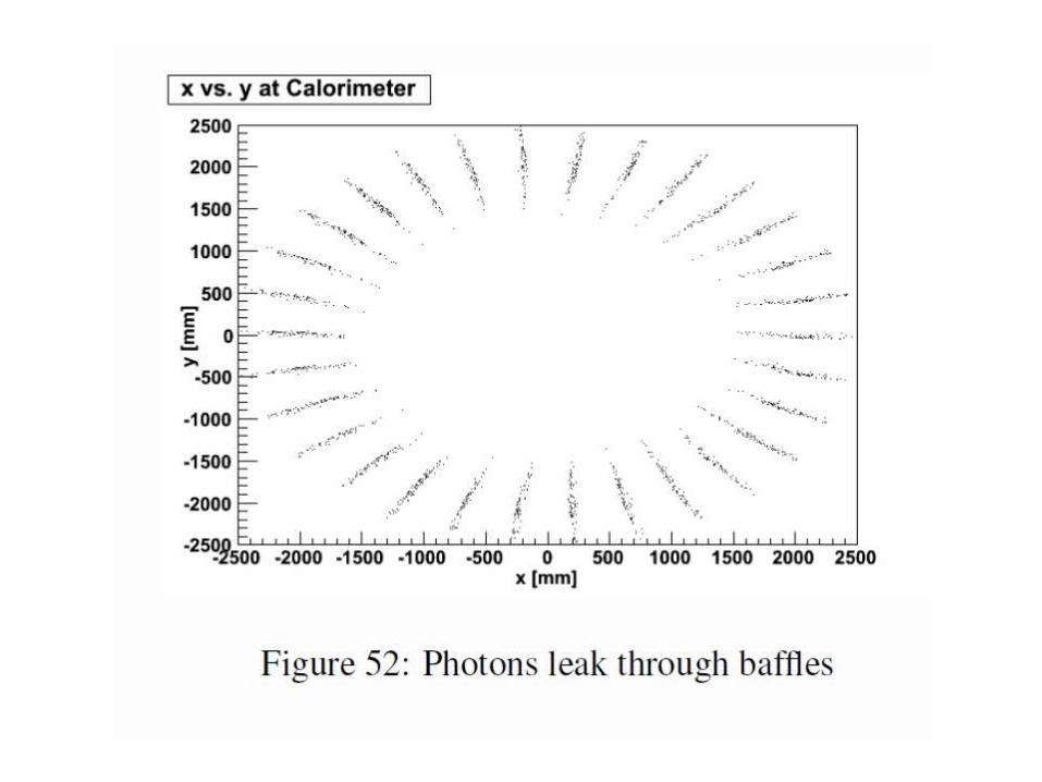
New Baffle(neutral acceptance)• ~0.02% along P
– At least 1 order less than current baffle
P Theta
P:Theta x

New baffle • Testing lead baffle effect on low energy EM entering EC• Energy flux of
– gamma in total drops by 6– electron in total drops by 8

New baffle • Testing lead baffle effect on low energy EM with energy deposited
in GEM• It drops by 5 on all planes

New baffle• Advantage
– Line of sight blocking doesn’t depend on field, nor target length– Straight slits, easier to make and align, cost saving(?)
• Disadvantage– Line of sight blocking depends vertex transverse size. Need small raster
and small target width. Any baffle will have this though.• PVDIS 6GeV used 2mmx2mm raster, what’s the minimum size for 12GeV?
– Large acceptance of pos particles, can EC and CC handle the rate?
• Other consideration– higher field will always help, especially the large P and corresponding
high x acceptance.

Eugene’s baffle has about 2 times better acceptance at higher P
• Original PVDIS design with small endcap and BaBar coil, the field reached 1.5T• Currently we have larger endcap to accommodate SIDIS and CLEO coil, the field
reaches 1.4T• It could be a better design or just with stronger field(?)
backup