Embed Size (px)
Citation preview
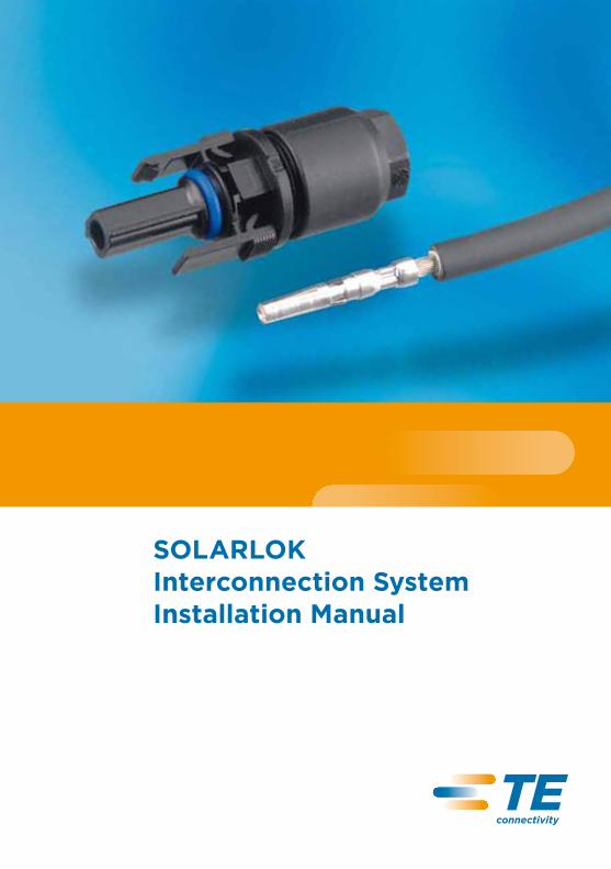
SOLARLOK Interconnection System Installation Manual

SOLARLOK Interconnection System
Installation Manual
te.com/solarAll specifications subject to change. Consult Tyco Electronics for latest specifications.
2-1773458-2 Issued 4-2011
1
(2) (3)
(1)
(2) (3)
(4)
1. Safety Note
n The SOLARLOK connector is to be used only to interconnect firmly fixed cables.
n Do not disconnect under electrical load!n Electrical current path should only be disconnected
using approved devices.n Only cables released from TE Connectivity are permitted
to be used with SOLARLOK component cable assemblies.n SOLARLOK component cable shall be labeled with label
PN 1718077-1 “Do not disconnect under load”.n To protect against shock, ensure that conductors and
their associated connectors are separated from opposite polarity components.
n Unconnected connectors must always be protected from pollution (e.g. dust, humidity, foreign particles, etc.), prior to installation. Do not leave unconnected (unprotected) connectors exposed to the environment. The usage of TE connector dust caps is strongly recommended.
n Connectors that are unmated in the field should also be protected from pollutants.
n Do NOT use any oil or lubricants during mounting.
2. Tools
(1) Stripping Tool 1.5 mm2 – 6.0 mm2, 10 AWG PN 4-1579002-2
(2) Crimping Tool 4.0 mm2 and 6.0 mm2, 10-12 AWG PN 1-1579004-2
(3) Extraction Tool all terminals PN 1102855-3
(4) Field Service Kit all in one PN 1534858-1
!

SOLARLOK Interconnection System2-1773458-2
Issued 4-2011
Installation Manual
te.com/solarAll specifications subject to change. Consult Tyco Electronics for latest specifications. 2
3. Assembly Steps
3.1 Using the appropriate wire stripping tool, strip the wire 9 mm ± 1 mm without damaging the strands.
3.2 Insert the stripped wire into the terminal wire crimp barrel until it stops. While holding the wire in place, squeeze the crimp tool handles together until the ratchet releases.
3.3 Press the seal and cable pinch ring assembly into the connector housing until it stops. If you use the pre-assembled connector kit, please go to 3.5!
3.4 Screw back shell nut onto connector housing.

SOLARLOK Interconnection System2-1773458-2
Issued 4-2011
Installation Manual
te.com/solarAll specifications subject to change. Consult Tyco Electronics for latest specifications.3
Pre-Assembled (Connector Kit)
3.5 Push contact with cable into the connector housing until you hear the contact give an audible click and you feel the contact reach the end position. To verify contact engagement, give a slight gentle pull back on the cable, to be sure that the contact is locked.
3.6 Tighten the cable screw lock. The initial assembly tightening torque is 1.3 + 0.2 Nm. For this, a slotted socket wrench with wrench size 13 mm, is recommended.
4. Connector Mating
n When mating the SOLARLOK connectors, connectors labelled with a “+” or “-” are keyed and can only be mated with equally (same polarity) marked and keyed connectors.
n The connector system is fully latched only when the latches have clicked onto the mating connector.
n The “neutral” designated male connector incorporates no keying features and may be freely mated to either “+” or “-” keyed plug connectors. The neutral product should not be used when maintaining polarity is critical. It is only permitted for serial connections.
“CLICK”

SOLARLOK Interconnection System2-1773458-2
Issued 4-2011
Installation Manual
te.com/solarAll specifications subject to change. Consult Tyco Electronics for latest specifications. 4
5. Wiring
Radius (r) min. 5x cable Ø
6. Connector Unmating
Depress locking latches Pull apart
r = correct!
!
SOLARLOK Interconnection System2-1773458-2
Issued 4-2011
Installation Manual
te.com/solarAll specifications subject to change. Consult Tyco Electronics for latest specifications.5
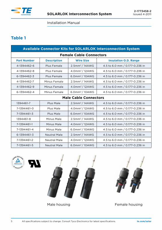
Table 1
Available Connector Kits for SOLARLOK Interconnection System
Female Cable ConnectorsPart Number Description Wire Size Insulation O.D. Range
4-1394462-6 Plus Female 2.5mm2 / 14AWG 4.5 to 6.0 mm / 0.177-0.236 in
4-1394462-8 Plus Female 4.0mm2 / 12AWG 4.5 to 6.0 mm / 0.177-0.236 in
6-1394462-3 Plus Female 6.0mm2 / 10AWG 4.5 to 6.0 mm / 0.177-0.236 in
4-1394462-7 Minus Female 2.5mm2 / 14AWG 4.5 to 6.0 mm / 0.177-0.236 in
4-1394462-9 Minus Female 4.0mm2 / 12AWG 4.5 to 6.0 mm / 0.177-0.236 in
6-1394462-4 Minus Female 6.0mm2 / 10AWG 4.5 to 6.0 mm / 0.177-0.236 in
Male Cable Connectors1394461-7 Plus Male 2.5mm2 / 14AWG 4.5 to 6.0 mm / 0.177-0.236 in
7-1394461-0 Plus Male 4.0mm2 / 12AWG 4.5 to 6.0 mm / 0.177-0.236 in
7-1394461-3 Plus Male 6.0mm2 / 10AWG 4.5 to 6.0 mm / 0.177-0.236 in
1394461-8 Minus Male 2.5mm2 / 14AWG 4.5 to 6.0 mm / 0.177-0.236 in
7-1394461-1 Minus Male 4.0mm2 / 12AWG 4.5 to 6.0 mm / 0.177-0.236 in
7-1394461-4 Minus Male 6.0mm2 / 10AWG 4.5 to 6.0 mm / 0.177-0.236 in
6-1394461-3 Neutral Male 2.5mm2 / 14AWG 4.5 to 6.0 mm / 0.177-0.236 in
7-1394461-2 Neutral Male 4.0mm2 / 12AWG 4.5 to 6.0 mm / 0.177-0.236 in
7-1394461-5 Neutral Male 6.0mm2 / 10AWG 4.5 to 6.0 mm / 0.177-0.236 in
Female housingMale housing
SOLARLOK Interconnection System2-1773458-2
Issued 4-2011
Installation Manual
te.com/solarAll specifications subject to change. Consult Tyco Electronics for latest specifications. 6
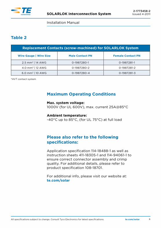
Table 2
Replacement Contacts (screw-machined) for SOLARLOK System
Wire Gauge | Wire Size Male Contact PN Female Contact PN
2.5 mm2 | 14 AWG 0-1987280-1 0-1987281-1
4.0 mm2 | 12 AWG 0-1987280-2 0-1987281-2
6.0 mm2 | 10 AWG 0-1987280-4 0-1987281-3
*HVT contact system
Maximum Operating Conditions
Max. system voltage: 1000V (for UL 600V), max. current 25A@85°C
Ambient temperature: -40°C up to 85°C, (for UL 75°C) at full load
Please also refer to the following specifications:
Application specification 114-18488-1 as well as instruction sheets 411-18305-1 and 114-94061-1 to ensure correct connector assembly and crimp quality. For additional details, please refer to product specification 108-18701.
For additional info, please visit our website at: te.com/solar
SOLARLOK Interconnection System2-1773458-2
Issued 4-2011
Installation Manual
te.com/solarAll specifications subject to change. Consult Tyco Electronics for latest specifications.7
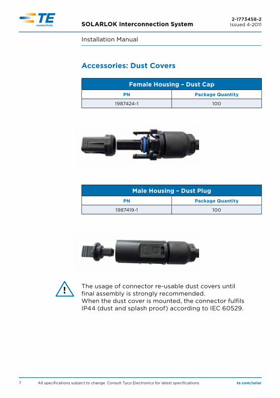
Accessories: Dust Covers
Female Housing – Dust CapPN Package Quantity
1987424-1 100
Male Housing – Dust PlugPN Package Quantity
1987419-1 100
The usage of connector re-usable dust covers until final assembly is strongly recommended.When the dust cover is mounted, the connector fulfils IP44 (dust and splash proof) according to IEC 60529.
!
SOLARLOK Interconnection System2-1773458-2
Issued 4-2011
Installation Manual
te.com/solarAll specifications subject to change. Consult Tyco Electronics for latest specifications. 8
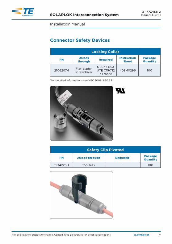
Connector Safety Devices
Locking Collar
PN Unlock through Required Instruction
SheetPackage Quantity
2106207-1 Flat-blade-screwdriver
NEC* / USAUTE C15-712
/ France408-10296 100
*for detailed informations see NEC 2008: 690.33
Safety Clip Pivoted
PN Unlock through Required Package Quantity
1534226-1 Tool less – 100
SOLARLOK Interconnection System2-1773458-2
Issued 4-2011
Installation Manual
te.com/solarAll specifications subject to change. Consult Tyco Electronics for latest specifications.9
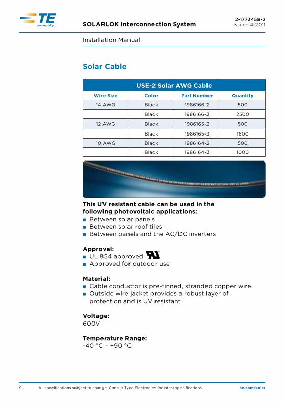
Solar Cable
USE-2 Solar AWG CableWire Size Color Part Number Quantity
14 AWG Black 1986166-2 500
Black 1986166-3 2500
12 AWG Black 1986165-2 500
Black 1986165-3 1600
10 AWG Black 1986164-2 500
Black 1986164-3 1000
This UV resistant cable can be used in the following photovoltaic applications:n Between solar panelsn Between solar roof tilesn Between panels and the AC/DC inverters
Approval:n UL 854 approvedn Approved for outdoor use
Material:n Cable conductor is pre-tinned, stranded copper wire.n Outside wire jacket provides a robust layer of
protection and is UV resistant
Voltage:600V
Temperature Range: -40 °C – +90 °C

SOLARLOK Interconnection System2-1773458-2
Issued 4-2011
Installation Manual
te.com/solarAll specifications subject to change. Consult Tyco Electronics for latest specifications. 10
Grounding Solutions
Grounding Clip and Grounding Bolt Only for solid un-insulated copper wire
PN Description Instruction Sheet
Package Quantity
1954381-1 12-10AWG Grounding Clip with Self-Tapping Screw 408-10160 100
1954381-2 12-10 AWG Grounding Clip with Screw and Nut 408-10160 100
1954381-3 12-10 AWG Grounding Clip with Screw, Nut and Locking Ring 408-10160 100
2106831-1 6-12 AWG Grounding Bolt,# 10-32 UNC Long Tail 408-10262 100
2058729-1 6-12 AWG Grounding Bolt,# 8-32 UNC Std Tail 408-10262 100
3 easy steps to ground your PV system:
1. Insert 2. Push 3. Ready!
Grounding Clip Grounding Bolt

te.com/solar
© 2011 Tyco Electronics Corporation, a TE Connectivity Ltd. company. All Rights Reserved.
2-1773458-2 CIS FP 3M 04/2011
SOLARLOK, TE Connectivity, TE connectivity (logo) and TE (logo) are trademarks.
Other logos, product and/or company names might be trademarks of their respective owners.
While TE has made every reasonable effort to ensure the accuracy of the information in this brochure, TE does not guarantee that it is
error-free, nor does TE make any other representation, warranty or guarantee that the information is accurate, correct, reliable or current.
TE reserves the right to make any adjustments to the information contained herein at any time without notice. TE expressly disclaims all
implied warranties regarding the information contained herein, including, but not limited to, any implied warranties of merchantability or
fitness for a particular purpose. The dimensions in this catalog are for reference purposes only and are subject to change without notice.
Specifications are subject to change without notice. Consult TE for the latest dimensions and design specifications.
FOR MORE INFORMATIONte.com/solar
TE Technical Support CenterInternet: te.com/helpUSA: +1 (800) 522-6752Canada: +1 (905) 475-6222Mexico +52 (0) 55-1106-0800Latin/S. America: +54 (0) 11-4733-2200 Germany: +49 (0) 6251-133-1999UK: +44 (0) 800-267666France: +33 (0) 1-3420-8686Netherlands: +31 (0) 73-6246-999China: +86 (0) 400-820-6015
Part numbers in this brochure are RoHS Compliant*, unless marked otherwise.*as defined www.te.com/leadfree