Embed Size (px)
Citation preview

8/7/2019 Solar Water Heating Notes
http://slidepdf.com/reader/full/solar-water-heating-notes 1/33
A
Presentation
onSolar Water Heating Systems
Shankar Singh Dhami
066msree516

8/7/2019 Solar Water Heating Notes
http://slidepdf.com/reader/full/solar-water-heating-notes 2/33
OUTLINE
Introduction
Natural Circulation Systems
Forced Circulation Systems
SWHs in low atmospheric temperature regionsBuilding heating:
The f- chart Method for Air and Water Systems,
Fundamentals of Building heating using SWH
Heating System Simulation,
Architectural Considerations and Calculation o
heating Loads

8/7/2019 Solar Water Heating Notes
http://slidepdf.com/reader/full/solar-water-heating-notes 3/33
Typical solar water heaters in
Market
Flat plate SWH
Vacuum tube SWH
3

8/7/2019 Solar Water Heating Notes
http://slidepdf.com/reader/full/solar-water-heating-notes 4/33

8/7/2019 Solar Water Heating Notes
http://slidepdf.com/reader/full/solar-water-heating-notes 5/33
Natural Circulation Systems (Thermo Siphon)
Hot Water Storage with insulation
Heat
Transport System
Cold Water Supply
hot waterdelivery
Electric
auxiliary heater
Thermostat
Drain
(Flush)

8/7/2019 Solar Water Heating Notes
http://slidepdf.com/reader/full/solar-water-heating-notes 6/33

8/7/2019 Solar Water Heating Notes
http://slidepdf.com/reader/full/solar-water-heating-notes 7/33
Working Principle of SWH
Hot
WaterOutlet
for Use
ColdWater
Supply
Cold waterinlet in
Collector
Hot wateroutlet from
Collector
Storage Tank
Collector H e i g h t
Temperature
1
2
4
3
1
2
3
4
Hot (Less denseexpanded fluid)
Cold (Dense fluid)
Principle of
Thermosyphon flow
7

8/7/2019 Solar Water Heating Notes
http://slidepdf.com/reader/full/solar-water-heating-notes 8/33
heattransportsystem
heat
exchanger
cold water supply
connection tohot water tap
control unit
powersupply
Heat Storage with insulation
expansion
vessel
backup heater
thermostatair releasevalve
(blockable)
pressurereleasevalve
(8 atm)
c h e c k
v a l v e
Forced Circulation Systems

8/7/2019 Solar Water Heating Notes
http://slidepdf.com/reader/full/solar-water-heating-notes 9/33
Indirect
Heating

8/7/2019 Solar Water Heating Notes
http://slidepdf.com/reader/full/solar-water-heating-notes 10/33
Water freezes below 0ocAntifreeze Ethylene Glycol
with in the closed circuit
ETC used
8/7/2019 Solar Water Heating Notes
http://slidepdf.com/reader/full/solar-water-heating-notes 11/33
Heat Tube Solar Collector
• Indirect Heating System
• Suitable for freeze prone area without anyalteration
• High efficient system• Can be used for high pressure (forced
convection ) system as well

8/7/2019 Solar Water Heating Notes
http://slidepdf.com/reader/full/solar-water-heating-notes 12/33
Flat-plate collectors
Coatings: Normal Matt Black Paint,
Selective coatings: black chrome,
black nickel, and aluminum oxidewith nickel
Insulation: Fiber Glass,
Rockwool, Vacuum
Absorber: Aluminum,
CupperCasing: GI sheet, Aluminum

8/7/2019 Solar Water Heating Notes
http://slidepdf.com/reader/full/solar-water-heating-notes 13/33
Forced-flow versus natural circulation SHW
systemsforced flow+ better performance
+ can be installed in large systems+ allows independent location of collector and hot water tank
– requires more components
–needs electrical energy for pumping and control
– is more expensive
natural circulation (thermosiphon)+ simple and require less components+ work without active control equipment
+ cheaper – not suitable for large systems
– less efficient
– storage tank must be located above the collectors

8/7/2019 Solar Water Heating Notes
http://slidepdf.com/reader/full/solar-water-heating-notes 14/33
Open- versus closed-loop SHW systems
Closed loop+ better performance – avoids air bubbles
+ Prevents siltation of the collectors
+ allows use of antifreeze
– Some temperature loss
– needs significantly more components – more expensive
– more difficult to manufacture
Open loop+ simple and require less components
+ Requires less tecnical skill+ Cheaper and less sensitive to flaws
– not suitable for frost area
– not suitable for poor quality water

8/7/2019 Solar Water Heating Notes
http://slidepdf.com/reader/full/solar-water-heating-notes 15/33
Heat for comfort in building can be providedfrom solar energy similar to Solar Heaters
Two most common heat transfer fluids are
water( or water and antifreeze mixtures) and air. The basic components are the collector, storage
unit, distributor and load (i.e., the house orbuilding to be heated)
Active Solar Heating and Passive Solar Heating The term solar house include the integral part of
the building elements that admit, absorb, storeand release solar energy and thus reduce theneeds for auxiliary energy for comfort heating.

8/7/2019 Solar Water Heating Notes
http://slidepdf.com/reader/full/solar-water-heating-notes 16/33
If solar energy is available and heat is not needed inthe building, energy gain from the collector is addedto storage.
If solar energy is available and heat is needed in thebuilding, energy gain from the collector is used tosupply the building need.
If solar energy is not available and heat is needed inthe building, and the storage unit has stored energy init, the stored energy is used to supply the buildingneed.
If solar energy is not available, heat is needed in thebuilding, and the storage unit has been depleted,auxiliary energy is used to supply the building need.

8/7/2019 Solar Water Heating Notes
http://slidepdf.com/reader/full/solar-water-heating-notes 17/33
Using air, the problem of freezing and boiling in the
collectors are eliminated and corrosion problems are reduced
Design parameters

8/7/2019 Solar Water Heating Notes
http://slidepdf.com/reader/full/solar-water-heating-notes 18/33
Design parameters
8/7/2019 Solar Water Heating Notes
http://slidepdf.com/reader/full/solar-water-heating-notes 19/33
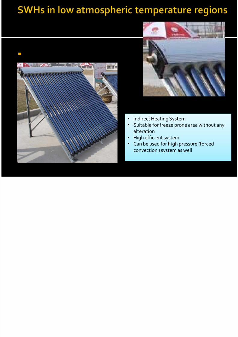
The f- chart method is used for estimating the annual thermalperformance of active heating systems for buildings(using eitherliquid or air) where the minimum temperature of energy delivery isnear 20oc.
The purpose of the method is to calculate f , the fraction of the hotwater load (total heating load) that is provided by the solar energyfor a given solar heating system (solar fraction). Once f iscalculated, the amount of renewable energy that displaces
conventional energy for water heating can be determined. The method enables the calculation of the monthly amount of
energy delivered by hot water systems with storage, given monthlyvalues of incident solar radiation, ambient temperature and load.

8/7/2019 Solar Water Heating Notes
http://slidepdf.com/reader/full/solar-water-heating-notes 20/33
The Primary Design variable is collector area; secondaryvariables are collector type, storage capacity, fluid flow ratesand load and collector heat exchange sizes.
The method is the correlation of the results of many
hundreds of thermal performance simulations of solarheating systems. f is the function of two dimensionless parameters i.e. one is
related to the ratio of collector losses to heating loads, andthe other is related to the ratio of absorbed solar radiation to
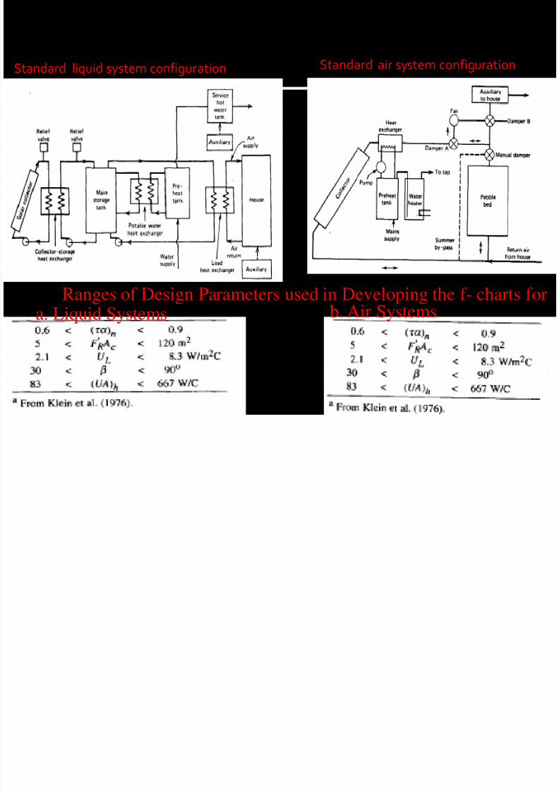
heating loads. f charts have been developed for three standard system
configuration, liquid and air systems for space (and hotwater) heating and systems for service hot water only.
8/7/2019 Solar Water Heating Notes
http://slidepdf.com/reader/full/solar-water-heating-notes 21/33
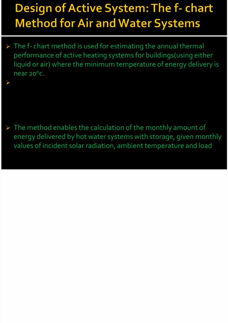
Two dimensionless groups X and Y are defined as:
andwhere ,
Ac = collector area,F’R = modified collector heat removal factor,
UL = collector overall loss cœfficient,
Tref = an empirical reference temperature equal to 100°C,
Ta = monthly average ambient temperature,L = monthly total heating load,
τα = collector’s monthly average transmittance - absorptance product,
HT = monthly average daily radiation incident on the collector surface
per unit area, and
N = number of days in the month.

8/7/2019 Solar Water Heating Notes
http://slidepdf.com/reader/full/solar-water-heating-notes 22/33
The fraction f of the monthly total load supplied by the solar water
heating system is given as a function of X and Y as:
The surface described by above equation is fairly smooth, so
extrapolation should not be a problem. If the formula predicts avalue of f less than 0, a value of 0 is used; if f is greater than 1, a
value of 1 is used.
For Liquid System
For Air System
F Li id S t F Ai S t

8/7/2019 Solar Water Heating Notes
http://slidepdf.com/reader/full/solar-water-heating-notes 23/33
f-Chart Correlation.
For Liquid System For Air System
8/7/2019 Solar Water Heating Notes
http://slidepdf.com/reader/full/solar-water-heating-notes 24/33
Standard liquid system configuration Standard air system configuration
Ranges of Design Parameters used in Developing the f- charts fora. Liquid Systems b. Air Systems
8/7/2019 Solar Water Heating Notes
http://slidepdf.com/reader/full/solar-water-heating-notes 25/33
The implicit assumptions of f-chart are Systems are well built Flow distribution to collectors is uniform, flow rates are as assumed,
system configurations are close to those for which thecorrelations were developed, and
Control strategies used are nearly those assumed in the f-chart development.
Three steps to check the results from f-chart Comparison with detailed simulation in many locations Laboratory measurements on experimental systems have
also been compared to f-chart Measurements on operating systems in the field also have
been used for comparison.

8/7/2019 Solar Water Heating Notes
http://slidepdf.com/reader/full/solar-water-heating-notes 26/33
Active solar heating system challenges to architectural design of buildings. Anybuilding design must be energy conserving, as solar energy and the fuels with
which it competes will be expensive.
Economics studies of active system solar heating indicated that the optimum
fractions of total annual loads ranges from zero to over three-fourths.
For some locations the architect must design into the building collector areas in
the range up to approximately one-half of the floor area of the house (depending
on the collector, the climate and the degree of insulation in the building)
The basic problem faced by the architects and engineers is to integrate the
collectors into the building design in such a way that thermal performance is
satisfactory and the structure is aesthetically satisfying
Collector should be oriented with the designed slope and azimuthal angle. Vertical collectors may be used for high latitudes to answer the problems of
integration of collectors into the buildings and avoiding snow accumulation
Space must be provided in the structure for energy storage units, piping and
ducts, controls, auxiliaries and all associated equipment.
8/7/2019 Solar Water Heating Notes
http://slidepdf.com/reader/full/solar-water-heating-notes 27/33
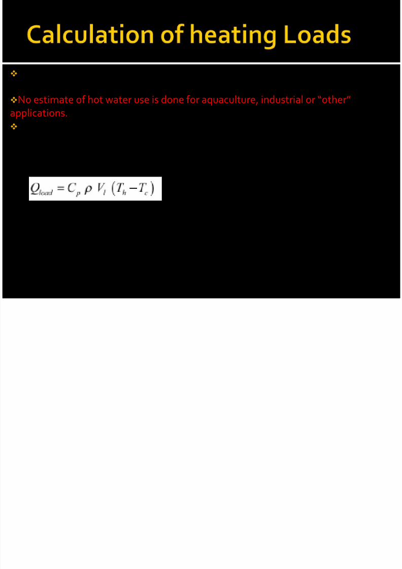
Load calculation is necessary for the service hot water (with or without storage)models. Hot water use estimates are provided for service hot water systems.
No estimate of hot water use is done for aquaculture, industrial or “other”
applications.
The actual load is calculated as the energy required to heat up mains water to the
specified hot water temperature. If Vl is the required amount of water and Th is therequired hot water temperature, both specified by the user, then the energy required
Qload is expressed as:
Where,Cp = heat capacitance of water (4,200 ( J/kg)/ºC),
ρ = density (1 kg/L), and
Tc = cold (mains) water temperature.
Qload is prorated by the number of days the system is used per week.

8/7/2019 Solar Water Heating Notes
http://slidepdf.com/reader/full/solar-water-heating-notes 28/33
The flow passagesconduct the working fluid
through it.
In water heating collector,cold water is let in, from
the bottom of collector
and hot water exits from
the top end.
8/7/2019 Solar Water Heating Notes
http://slidepdf.com/reader/full/solar-water-heating-notes 29/33

8/7/2019 Solar Water Heating Notes
http://slidepdf.com/reader/full/solar-water-heating-notes 30/33

8/7/2019 Solar Water Heating Notes
http://slidepdf.com/reader/full/solar-water-heating-notes 31/33
Thank youfor your kind attention!

8/7/2019 Solar Water Heating Notes
http://slidepdf.com/reader/full/solar-water-heating-notes 32/33

8/7/2019 Solar Water Heating Notes
http://slidepdf.com/reader/full/solar-water-heating-notes 33/33