Embed Size (px)
Citation preview
Solarradioemissionbelowtheionosphericcutoff:measurements
StuartD.BaleUniversityofCalifornia,Berkeley
outline1)frequencyrange
a)needtobeinspace!2)spacecra>measurements
a)Wind,STEREO I)superheterodynereceivers II)spacecra>electromagneGccompaGbility-thepicketfence III)antennapaJernanddirecGon-findingb)SolarProbePlusandSolarOrbiter I)RadioFrequencySpectrometeronSPP A)PolyphaseFilterbank(PFB)
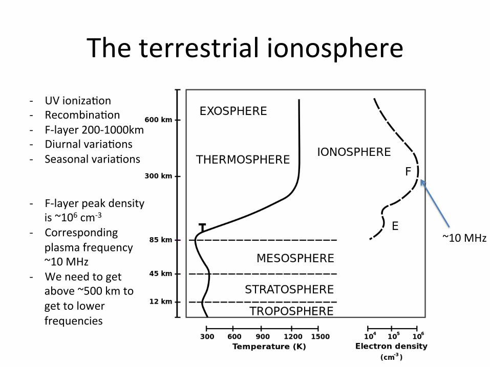
Theterrestrialionosphere- UVionizaGon- RecombinaGon- F-layer200-1000km- DiurnalvariaGons- SeasonalvariaGons
- F-layerpeakdensityis~106cm-3
- Correspondingplasmafrequency~10MHz
- Weneedtogetabove~500kmtogettolowerfrequencies
~10MHz
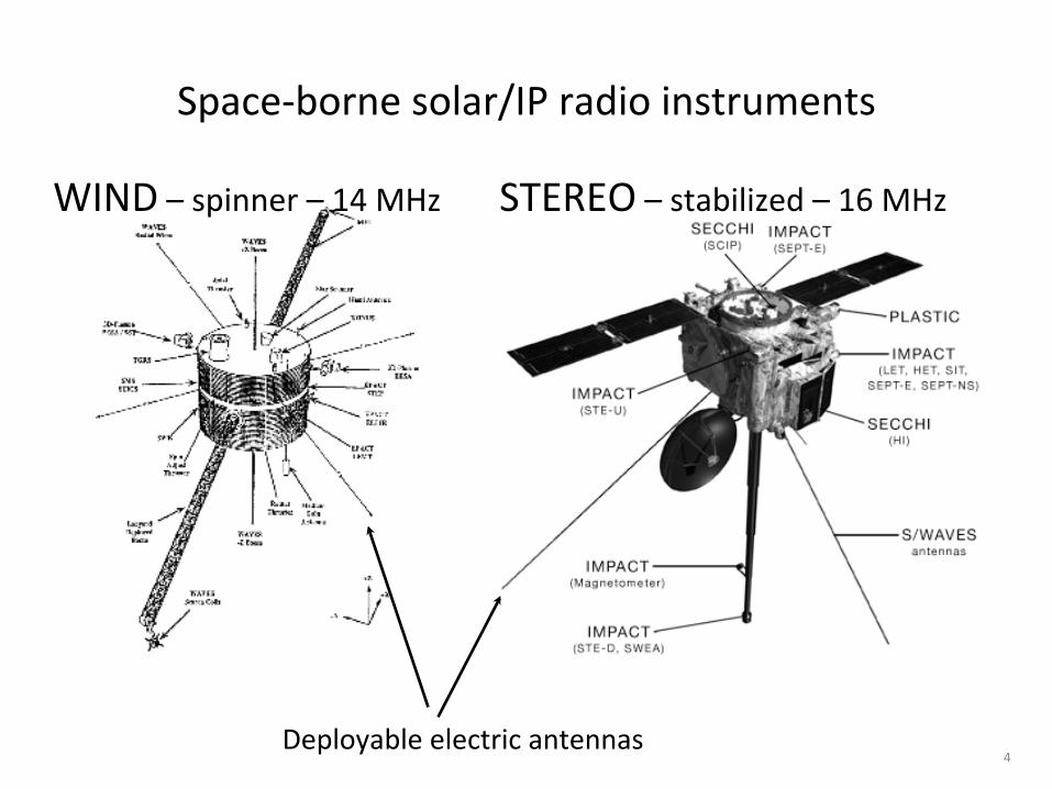
Space-bornesolar/IPradioinstruments
4Deployableelectricantennas
STEREO–stabilized–16MHzWIND–spinner–14MHz
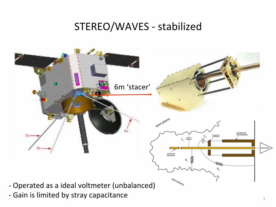
STEREO/WAVES-stabilized
5
-Operatedasaidealvoltmeter(unbalanced)-Gainislimitedbystraycapacitance
6m‘stacer’
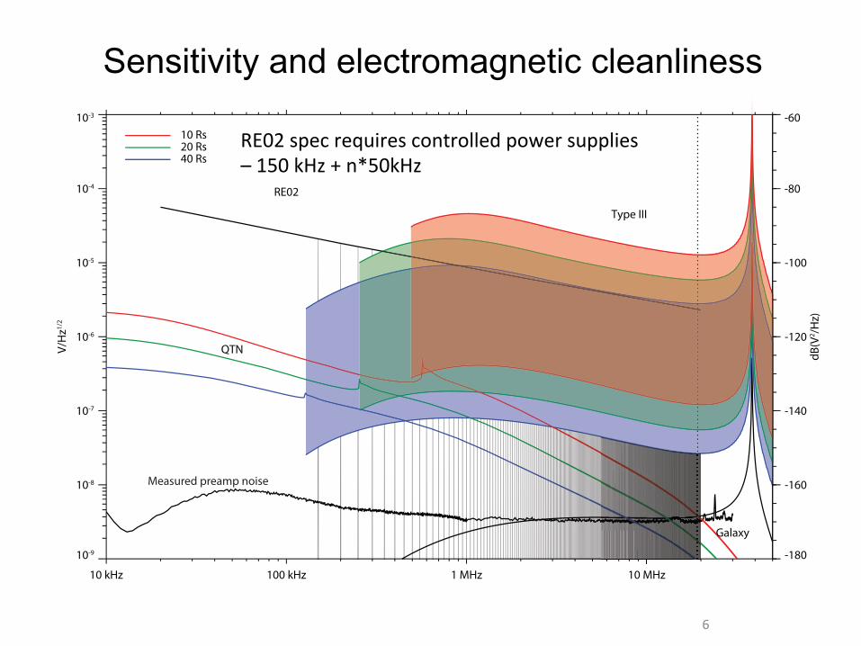
Sensitivity and electromagnetic cleanliness
6
10 kHz 100 kHz zHM 01zHM 1
10-9
10-8
10-7
10-6
10-5
10-4
10-3
V/H
z1/2
-180
-160
-140
-120
-100
-80
-60
dB(V
2 /Hz)
Galaxy
QTN
Type III
RE02
10 Rs20 Rs40 Rs
Measured preamp noise
RE02specrequirescontrolledpowersupplies–150kHz+n*50kHz
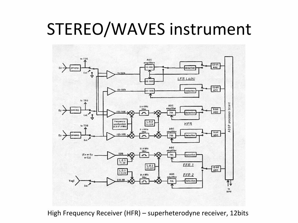
STEREO/WAVESinstrument
HighFrequencyReceiver(HFR)–superheterodynereceiver,12bits
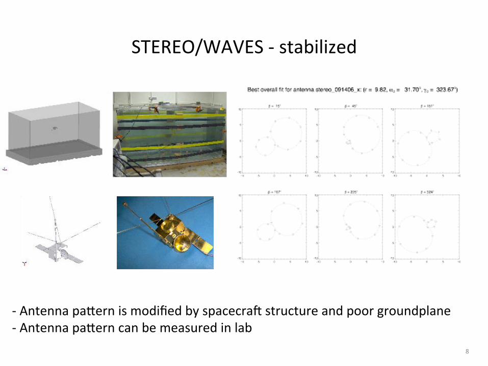
STEREO/WAVES-stabilized
8
-AntennapaJernismodifiedbyspacecra>structureandpoorgroundplane-AntennapaJerncanbemeasuredinlab

RadiodirecGon-finding
9
IsolatedtypeIIIburst
Powerandangles(red=A,blue=B)
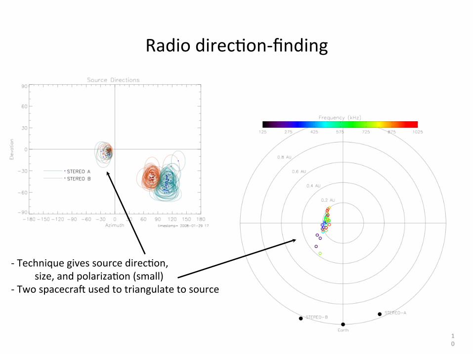
RadiodirecGon-finding
10
-TechniquegivessourcedirecGon,size,andpolarizaGon(small)
-Twospacecra>usedtotriangulatetosource
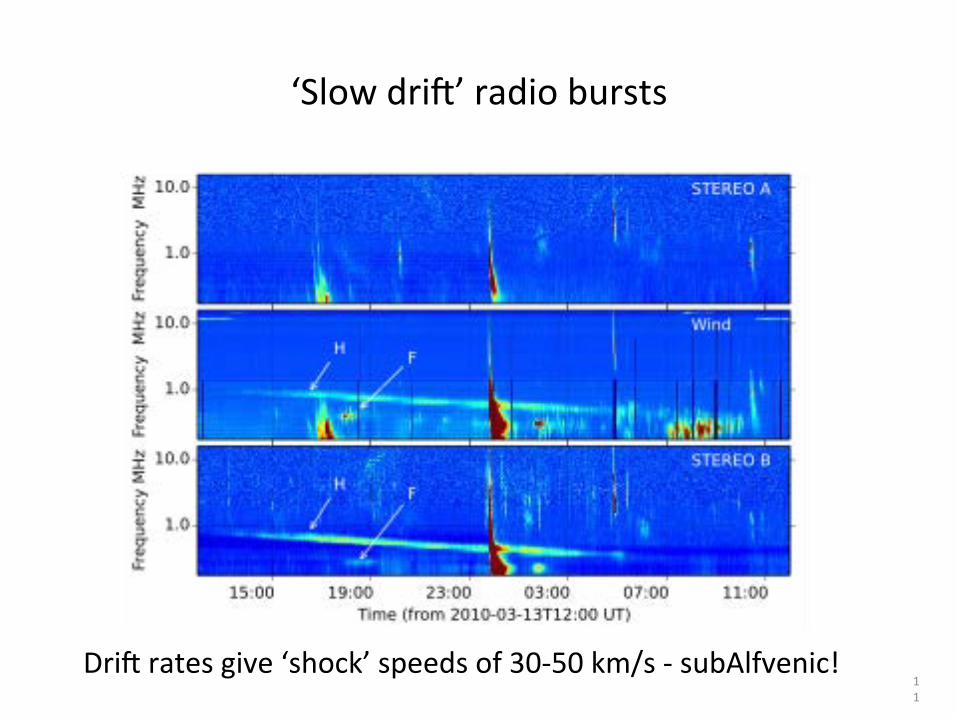
‘Slowdri>’radiobursts
11
Dri>ratesgive‘shock’speedsof30-50km/s-subAlfvenic!
‘Slowdri>’radiobursts
12
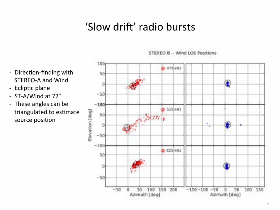
- DirecGon-findingwithSTEREO-AandWind
- EclipGcplane- ST-A/Windat72°- TheseanglescanbetriangulatedtoesGmatesourceposiGon
‘Slowdri>’radiobursts
13
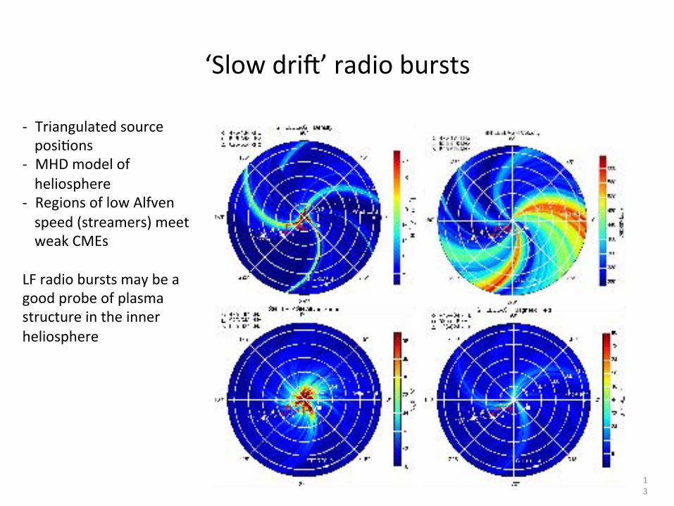
- TriangulatedsourceposiGons
- MHDmodelofheliosphere
- RegionsoflowAlfvenspeed(streamers)meetweakCMEs
LFradioburstsmaybeagoodprobeofplasmastructureintheinnerheliosphere
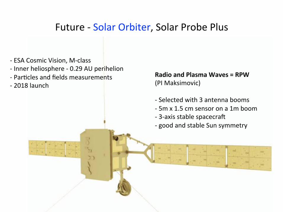
Future-SolarOrbiter,SolarProbePlus
14
RadioandPlasmaWaves=RPW(PIMaksimovic)-Selectedwith3antennabooms-5mx1.5cmsensorona1mboom-3-axisstablespacecra>-goodandstableSunsymmetry
RadioandPlasmaWaves=RPW(PIMaksimovic)-Selectedwith3antennabooms-5mx1.5cmsensorona1mboom-3-axisstablespacecra>-goodandstableSunsymmetry
-ESACosmicVision,M-class-Innerheliosphere-0.29AUperihelion-ParGclesandfieldsmeasurements-2018launch

NASASolarProbePlus(SPP)
2018launchInPhaseB~9.5Rsperihelion~90dayorbit7yrmission
8/25/15
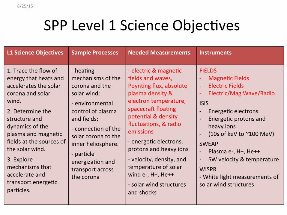
SPPLevel1ScienceObjecGvesL1ScienceObjec7ves SampleProcesses NeededMeasurements Instruments
1.Tracetheflowofenergythatheatsandacceleratesthesolarcoronaandsolarwind.
2.DeterminethestructureanddynamicsoftheplasmaandmagneGcfieldsatthesourcesofthesolarwind.
3.ExploremechanismsthataccelerateandtransportenergeGcparGcles.
-heaGngmechanismsofthecoronaandthesolarwind;-environmentalcontrolofplasmaandfields;-connecGonofthesolarcoronatotheinnerheliosphere.-parGcleenergizaGonandtransportacrossthecorona
-electric&magneGcfieldsandwaves,PoynGngflux,absoluteplasmadensity&electrontemperature,spacecra>floaGngpotenGal&densityfluctuaGons,&radioemissions-energeGcelectrons,protonsandheavyions
-velocity,density,andtemperatureofsolarwinde-,H+,He++-solarwindstructuresandshocks
FIELDS- MagneGcFields- ElectricFields- Electric/MagWave/RadioISIS- EnergeGcelectrons- EnergeGcprotonsand
heavyions- (10sofkeVto~100MeV)SWEAP- Plasmae-,H+,He++- SWvelocity&temperatureWISPR-Whitelightmeasurementsofsolarwindstructures
8/25/15
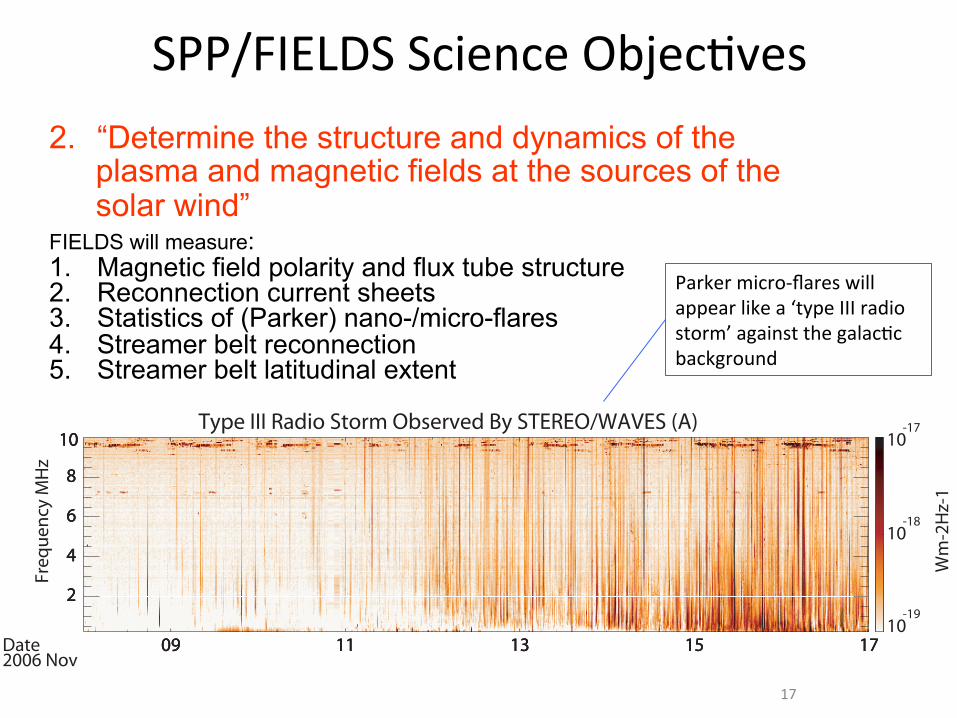
2. “Determine the structure and dynamics of the plasma and magnetic fields at the sources of the solar wind”
FIELDS will measure: 1. Magnetic field polarity and flux tube structure 2. Reconnection current sheets 3. Statistics of (Parker) nano-/micro-flares 4. Streamer belt reconnection 5. Streamer belt latitudinal extent
– 15 –
09 11 13 15 17
2
4
6
8
10
Freq
uenc
y M
Hz
Type III Radio Storm Observed By STEREO/WAVES (A)
09 11 13 15 17
2
4
6
8
10
09 11 13 15 17
2
4
6
8
10
10-19
10-18
10-17
Wm
-2H
z-1
Date2006 Nov
Fig. 1.— STEREO-A S/WAVES observations of radio emission from 8 Nov 2006 0000UT to
17 Nov 2006 0000UT (9 days). A type III storm associated with Active Region 10923 was
observed, beginning on 11 Nov. Terrestrial RFI is observed periodically between 9.5 MHz
and 10 MHz but is avoided in the analysis. The white line at 2 MHz is an artifact of the
plotting software.
STEREO A Type III storm 2006-11-11/0000 UT - 2006-11-17/0000 UT
10-19 10-18 10-17 10-16 10-15
S: Burst Flux Density (3.025 MHz)
1
10
100
1000
No.
of B
urst
s ab
ove S
Threshold = 5E-019
N_bursts = 824
Max. Likelihood Fit = -2.16
Uncertainty in Fit = 0.04
Fig. 2.— Cumulative distribution of burst brightness at 3.025 MHz, together with the
maximum likelihood fit.
Parkermicro-flareswillappearlikea‘typeIIIradiostorm’againstthegalacGcbackground
17
SPP/FIELDSScienceObjecGves
8/25/15 ISSIMicrophysicsofCosmicPlasmas06-10 Solar Probe Plus Critical Design Review
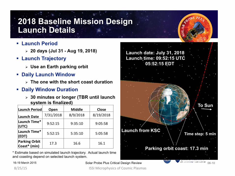
2018 Baseline Mission Design Launch Details ! Launch Period
" 20 days (Jul 31 - Aug 19, 2018) ! Launch Trajectory
" Use an Earth parking orbit ! Daily Launch Window
" The one with the short coast duration ! Daily Window Duration
" 30 minutes or longer (TBR until launch system is finalized)
Launch date: July 31, 2018 Launch time: 09:52:15 UTC
05:52:15 EDT
Launch from KSC Time step: 5 min
Parking orbit coast: 17.3 min
To Sun Launch!Period! Open! Middle! Close!
Launch!Date! 7/31/2018( 8/9/2018( 8/19/2018(
Launch!Time*!(UTC)!
9:52:15( 9:35:10( 9:05:58(
Launch!Time*!(EDT)!
5:52:15( 5:35:10( 5:05:58(
Parking!Orbit!Coast*!(min)!
17.3( 16.6( 16.1(
* Estimate based on simulated launch trajectory. Actual launch time and coasting depend on selected launch system.
16-19 March 2015
8/25/15 ISSIMicrophysicsofCosmicPlasmas06-13 Solar Probe Plus Critical Design Review
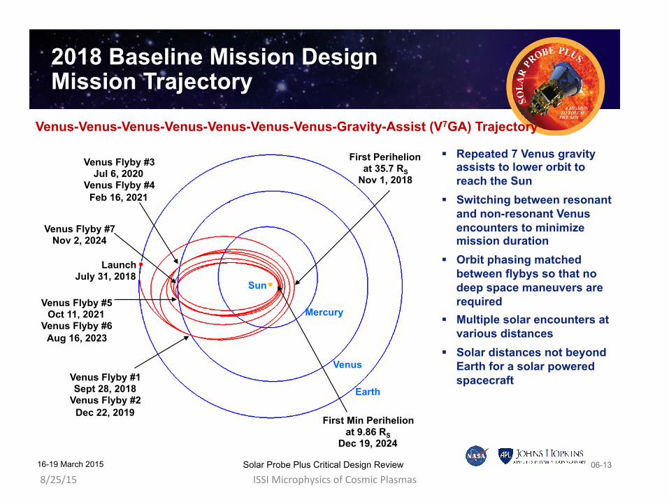
2018 Baseline Mission Design Mission Trajectory
Venus Flyby #7 Nov 2, 2024
Mercury
Venus
Earth
Sun
First Perihelion at 35.7 RS
Nov 1, 2018
First Min Perihelion at 9.86 RS
Dec 19, 2024
Venus Flyby #1 Sept 28, 2018
Venus Flyby #2 Dec 22, 2019
Venus Flyby #3 Jul 6, 2020
Venus Flyby #4 Feb 16, 2021
Venus Flyby #5 Oct 11, 2021
Venus Flyby #6 Aug 16, 2023
Launch July 31, 2018
Venus-Venus-Venus-Venus-Venus-Venus-Venus-Gravity-Assist (V7GA) Trajectory
! Repeated 7 Venus gravity assists to lower orbit to reach the Sun
! Switching between resonant and non-resonant Venus encounters to minimize mission duration
! Orbit phasing matched between flybys so that no deep space maneuvers are required
! Multiple solar encounters at various distances
! Solar distances not beyond Earth for a solar powered spacecraft
16-19 March 2015
8/25/15 ISSIMicrophysicsofCosmicPlasmas06-17 Solar Probe Plus Critical Design Review
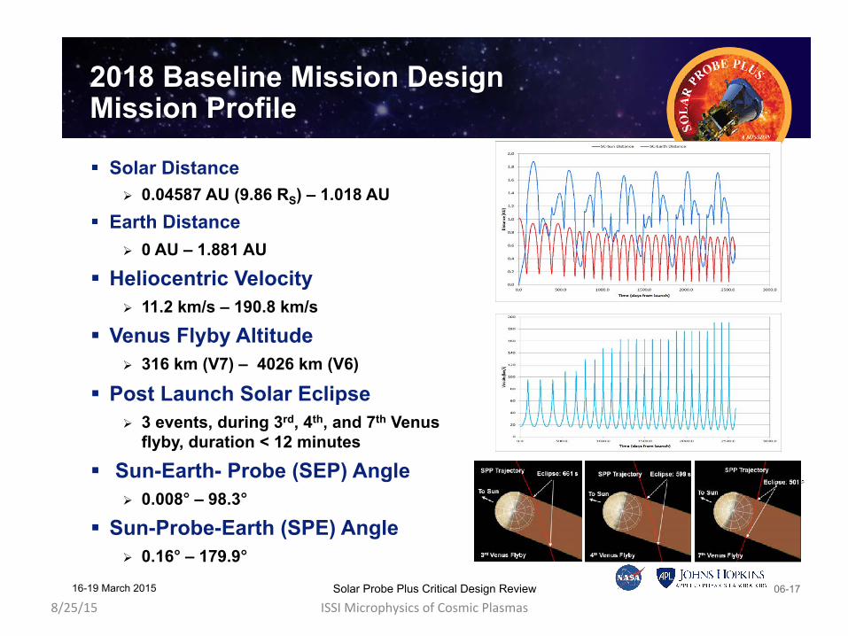
2018 Baseline Mission Design Mission Profile
! Solar Distance " 0.04587 AU (9.86 RS) – 1.018 AU
! Earth Distance " 0 AU – 1.881 AU
! Heliocentric Velocity " 11.2 km/s – 190.8 km/s
! Venus Flyby Altitude " 316 km (V7) – 4026 km (V6)
! Post Launch Solar Eclipse " 3 events, during 3rd, 4th, and 7th Venus
flyby, duration < 12 minutes ! Sun-Earth- Probe (SEP) Angle
" 0.008° – 98.3°
! Sun-Probe-Earth (SPE) Angle " 0.16° – 179.9°
16-19 March 2015
8/25/1514-4 Solar Probe Plus Critical Design Review
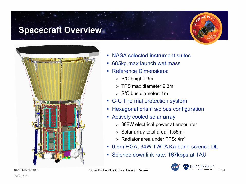
Spacecraft Overview
! NASA selected instrument suites ! 685kg max launch wet mass ! Reference Dimensions:
" S/C height: 3m " TPS max diameter:2.3m " S/C bus diameter: 1m
! C-C Thermal protection system ! Hexagonal prism s/c bus configuration ! Actively cooled solar array
" 388W electrical power at encounter " Solar array total area: 1.55m2
" Radiator area under TPS: 4m2
! 0.6m HGA, 34W TWTA Ka-band science DL ! Science downlink rate: 167kbps at 1AU
16-19 March 2015
8/25/15 ISSIMicrophysicsofCosmicPlasmas09-3 Solar Probe Plus Critical Design Review
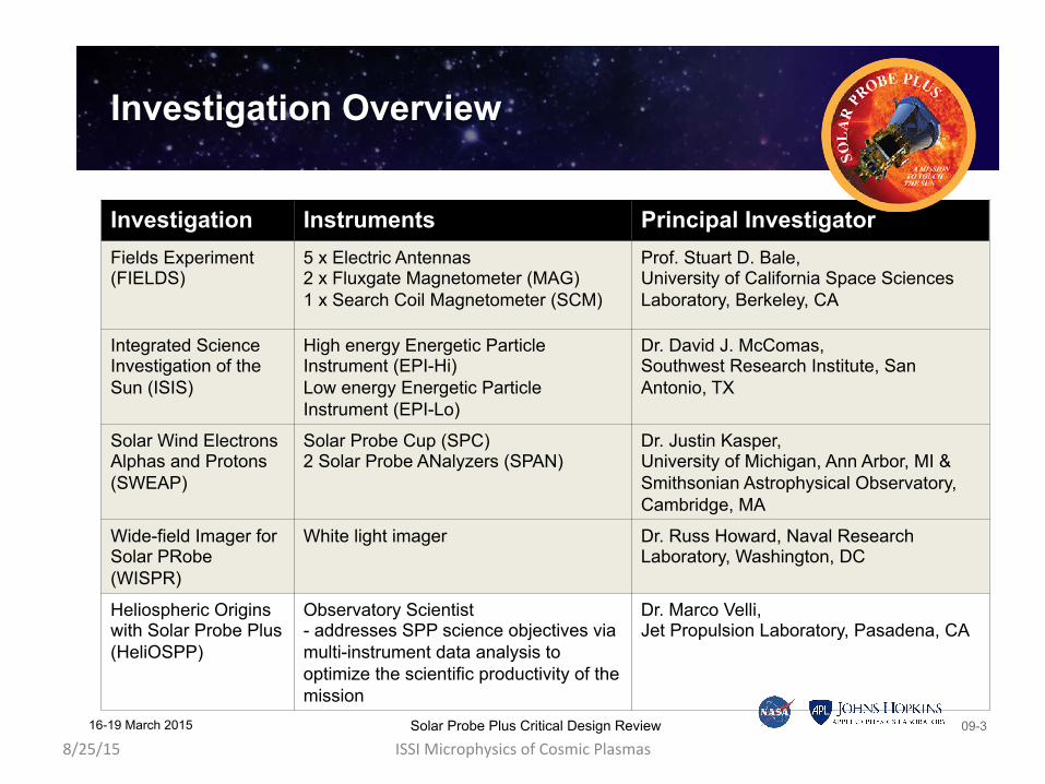
Investigation Overview
Investigation Instruments Principal Investigator Fields Experiment (FIELDS)
5 x Electric Antennas 2 x Fluxgate Magnetometer (MAG) 1 x Search Coil Magnetometer (SCM)
Prof. Stuart D. Bale, University of California Space Sciences Laboratory, Berkeley, CA
Integrated Science Investigation of the Sun (ISIS)
High energy Energetic Particle Instrument (EPI-Hi) Low energy Energetic Particle Instrument (EPI-Lo)
Dr. David J. McComas, Southwest Research Institute, San Antonio, TX
Solar Wind Electrons Alphas and Protons (SWEAP)
Solar Probe Cup (SPC) 2 Solar Probe ANalyzers (SPAN)
Dr. Justin Kasper, University of Michigan, Ann Arbor, MI & Smithsonian Astrophysical Observatory, Cambridge, MA
Wide-field Imager for Solar PRobe (WISPR)
White light imager Dr. Russ Howard, Naval Research Laboratory, Washington, DC
Heliospheric Origins with Solar Probe Plus (HeliOSPP)
Observatory Scientist - addresses SPP science objectives via multi-instrument data analysis to optimize the scientific productivity of the mission
Dr. Marco Velli, Jet Propulsion Laboratory, Pasadena, CA
16-19 March 2015
8/25/1509-4 Solar Probe Plus Critical Design Review
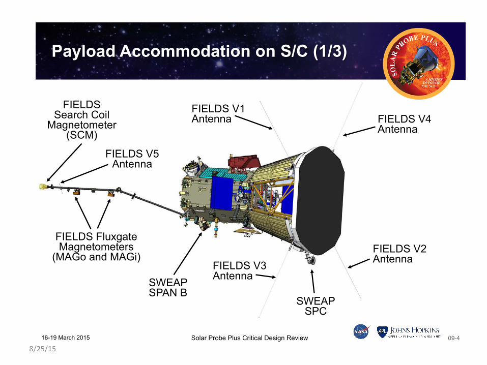
SWEAP SPC
FIELDS Search Coil
Magnetometer (SCM)
FIELDS Fluxgate Magnetometers
(MAGo and MAGi)
FIELDS V5 Antenna
FIELDS V1 Antenna FIELDS V4
Antenna
FIELDS V3 Antenna
FIELDS V2 Antenna
Payload Accommodation on S/C (1/3)
SWEAP SPAN B
16-19 March 2015
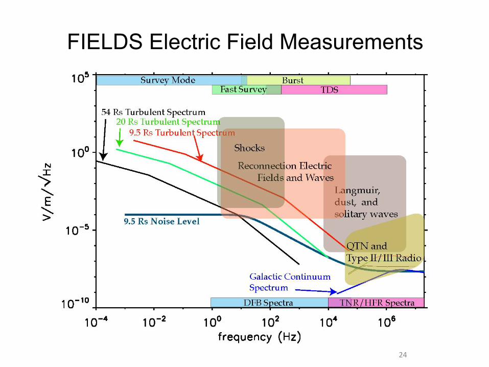
FIELDS Electric Field Measurements
24

V1-V4electricsensors
25
V2
V1
V4
V3
Base/Hinge and stub (30 cm) – voltage biased
Whip (2 m length) – current-biased
Mid-Mount Whip Release
Tip fork
(currentlybeingworkedgivennewDeltaIV-Hlaunchloadspecs)
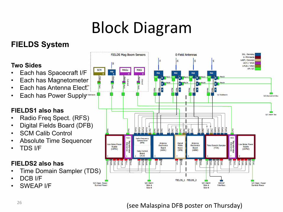
BlockDiagram
26
FIELDS System Two Sides • Each has Spacecraft I/F • Each has Magnetometer • Each has Antenna Elect. • Each has Power Supply FIELDS1 also has • Radio Freq Spect. (RFS) • Digital Fields Board (DFB) • SCM Calib Control • Absolute Time Sequencer • TDS I/F
FIELDS2 also has • Time Domain Sampler (TDS) • DCB I/F • SWEAP I/F (seeMalaspinaDFBposteronThursday)
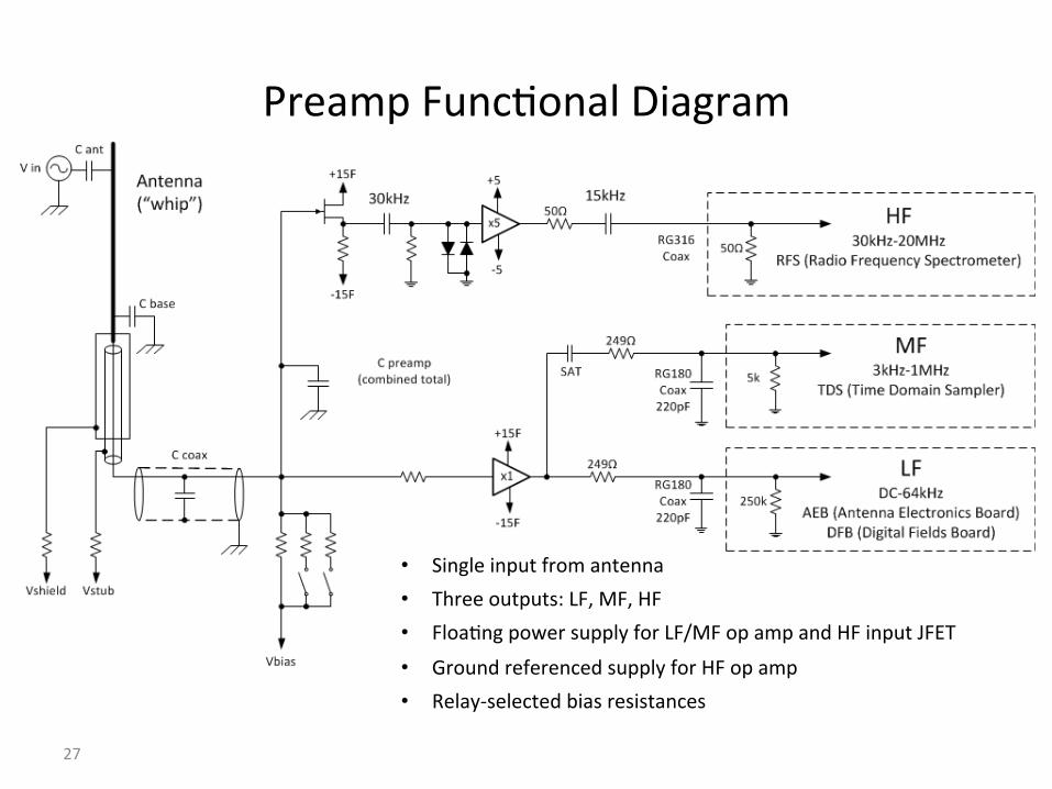
PreampFuncGonalDiagram
27
• Singleinputfromantenna• Threeoutputs:LF,MF,HF• FloaGngpowersupplyforLF/MFopampandHFinputJFET
• GroundreferencedsupplyforHFopamp• Relay-selectedbiasresistances

28
• 2channel,40MSPS,basebanddigitalreceiver• PolyphaseFilterBankprovides>120dBnarrowbandrejecGon
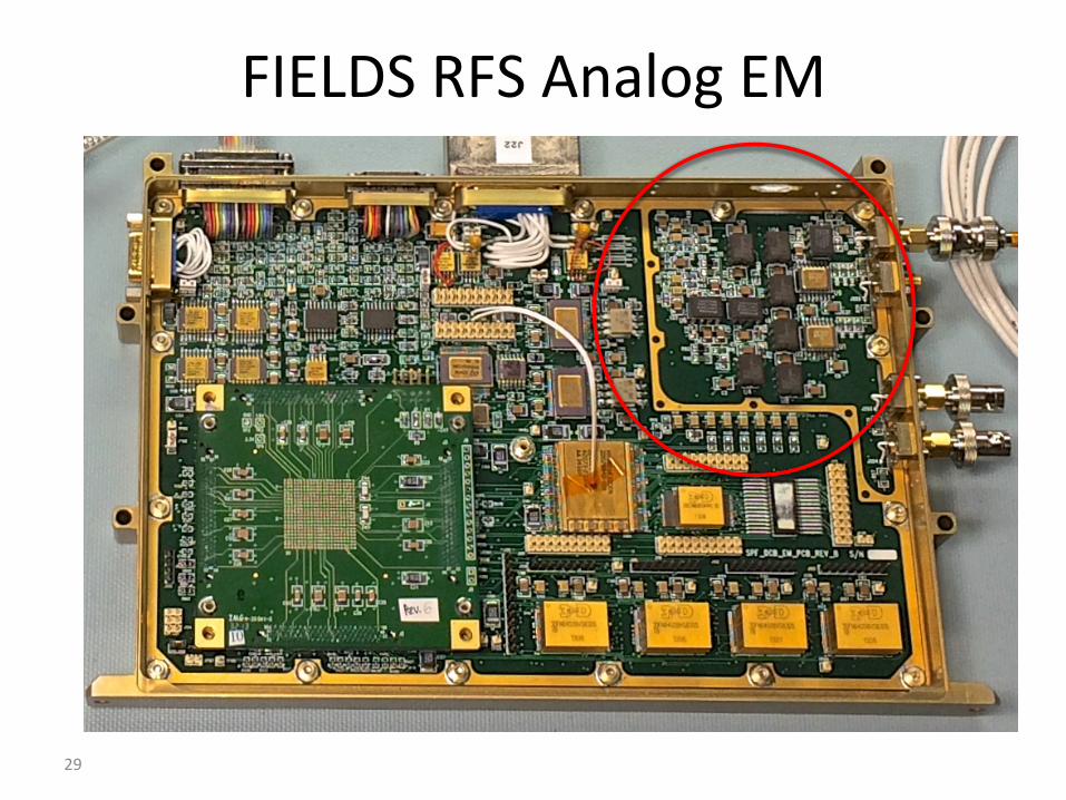
FIELDSRFSAnalogEM
29

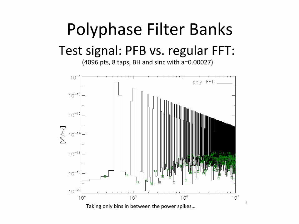
PolyphaseFilterBanksTest*signal:*PFB*vs.*regular*FFT:*
(4096*pts,*8*taps,*BH*and*sinc*with*a=0.00027)*
4*
PolyphaseFilterBanksTest*signal:*PFB*vs.*regular*FFT:*
*(4096*pts,*8*taps,*BH*and*sinc*with*a=0.00027)*
Taking*only*bins*in*between*the*power*spikes…*5*
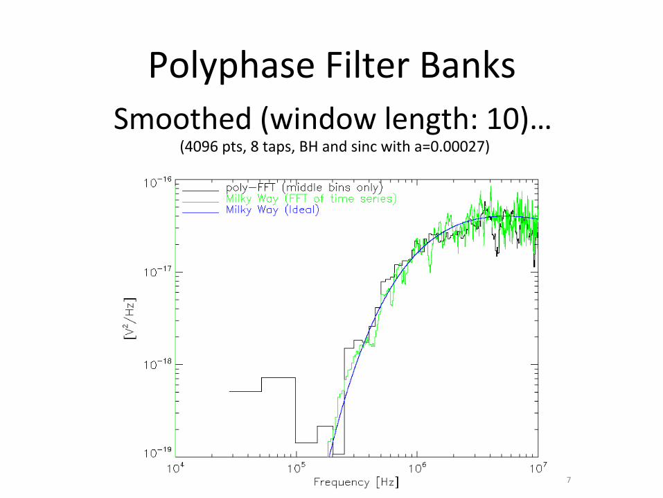
PolyphaseFilterBanksSmoothed*(window*length:*10)…*
*(4096*pts,*8*taps,*BH*and*sinc*with*a=0.00027)*
7*
Summary
• Radiomeasurements<10MHzmustbemadefromspace
• Spinnerand3-axisstablizedspacecra>canbeusedfor‘direcGon-finding’analysis
• Spacecra>andinstrument(powersupply)noisecandominate
• SolarOrbiterandSolarProbePlusin2018


![A Model Independent Ultraviolet Cutoff for Theories with ...arXiv:0812.4254v2 [hep-th] 13 Feb 2009 A Model Independent Ultraviolet Cutoff for Theories with Charged Massive Higher](https://img.dokumen.tips/doc/110x75/6088cbb2eb8d3351c25cc4c6/a-model-independent-ultraviolet-cutoi-for-theories-with-arxiv08124254v2.jpg)