Embed Size (px)
Citation preview

Cornwall Solar Project
Construction Plan Report
June 5, 2012

Cornwall Solar Inc.
Toronto, ON
Construction Plan Report
Cornwall Solar Project
H336742-2000-07-124-0008 Rev. 0
June 5, 2012

Cornwall Solar Inc. - Cornwall Solar Project Construction Plan Report
H336742-2000-07-124-0008, Rev. 0, Page i
© Hatch 2012/06
Report Disclaimer
This report has been prepared by Hatch Ltd. (Hatch) for the sole and exclusive use of Cornwall Solar, Inc. (hereinafter referred to as “Cornwall Solar” the “Client” or the “Proponent”) for the purpose of assisting the management of the Client in making decisions with respect to the development of a proposed solar photovoltaic project and shall not be (a) used for any other purpose, or (b) provided to, relied upon or used by any third party.
This report contains opinions, conclusions and recommendations made by Hatch, using its professional judgment and reasonable care. Any use of or reliance upon this report and estimate by the Proponent and the Client is subject to the following conditions:
the report being read in the context of and subject to the terms of the agreement between Hatch and the Client including any methodologies, procedures, techniques, assumptions and other relevant terms or conditions that were specified or agreed therein;
the report being read as a whole, with sections or parts hereof read or relied upon in context;
the conditions of the site may change over time (or may have already changed) due to natural forces or human intervention, and Hatch takes no responsibility for the impact that such changes may have on the accuracy or validity of the observations, conclusions and recommendations set out in this report; and
the report is based on information made available to Hatch by the Proponent and/or the Client or by certain third parties; and unless stated otherwise in the Agreement, Hatch has not verified the accuracy, completeness or validity of such information, makes no representation regarding its accuracy and hereby disclaims any liability in connection therewith.

Cornwall Solar Inc. - Cornwall Solar Project Construction Plan Report
H336742-2000-07-124-0008, Rev. 0, Page ii
© Hatch 2012/06
Project Report
June 5, 2012
Cornwall Solar Inc.
Cornwall Solar Project
Construction Plan Report
Table of Contents
1. Introduction ............................................................................................................................................ 1
1.1 Project Description ........................................................................................................................ 1 1.2 Renewable Energy Approval Legislative Requirements ................................................................... 1 1.3 Purpose of Report .......................................................................................................................... 1
2. Construction Plan .................................................................................................................................... 5
2.1 Construction Overview .................................................................................................................. 5 2.2 Construction Methodology ............................................................................................................. 6
2.2.1 Safety Management .............................................................................................................. 6 2.2.2 Workforce ............................................................................................................................ 6 2.2.3 Vehicle Access ..................................................................................................................... 6 2.2.4 Temporary Facilities ............................................................................................................. 9 2.2.5 Construction Materials ......................................................................................................... 9 2.2.6 Construction Equipment ....................................................................................................... 9 2.2.7 Fencing, Security Gate and Lighting ................................................................................... 11 2.2.8 Fire Control Plan ................................................................................................................ 11 2.2.9 Drainage ............................................................................................................................ 11 2.2.10 Landscaping and Vegetation ............................................................................................... 12 2.2.11 Power and Communication ................................................................................................ 12 2.2.12 Water Usage ...................................................................................................................... 12 2.2.13 Housekeeping and Waste Management .............................................................................. 12
2.3 Construction Phases ..................................................................................................................... 13 2.3.1 Phase 1 - Site Preparation ................................................................................................... 13
2.3.1.1 Site Survey and Staking ............................................................................................. 13 2.3.1.2 Erosion and Sedimentation Controls ......................................................................... 13 2.3.1.3 Construction Staging/Laydown Area ......................................................................... 13 2.3.1.4 Tree Cutting and Vegetation Removal ....................................................................... 13 2.3.1.5 Excavations, Fill Placement and Surface Grading ...................................................... 14 2.3.1.6 Access Roads ............................................................................................................ 14 2.3.1.7 Surface Drainage ...................................................................................................... 14 2.3.1.8 Building Removal ..................................................................................................... 15
2.3.2 Phase 2 - Construction and Installation ............................................................................... 15 2.3.2.1 Building Foundations ................................................................................................ 15 2.3.2.2 Trenches for Cable and Instrumentation Control ....................................................... 15 2.3.2.3 PV Module Mounting System, Supports and Foundations ......................................... 16

Cornwall Solar Inc. - Cornwall Solar Project Construction Plan Report
H336742-2000-07-124-0008, Rev. 0, Page iii
© Hatch 2012/06
2.3.2.4 Solar PV Modules ..................................................................................................... 16 2.3.2.5 Electrical System ....................................................................................................... 16 2.3.2.6 Substation Yard and Switch House ........................................................................... 17
2.3.3 Phase 3 - Testing and Commissioning ................................................................................. 17 2.3.4 Phase 4 - Site Restoration ................................................................................................... 17
3. Environmental Effects ............................................................................................................................ 19
3.1 Definition of “Environment” ......................................................................................................... 19 3.2 Existing Conditions ...................................................................................................................... 19 3.3 Potential Negative Environmental Effects and Mitigation Measures ............................................... 20 3.4 Natural Environment Components ............................................................................................... 20
3.4.1 Soil Quality and Quantity ................................................................................................... 20 3.4.1.1 Soil Erosion .............................................................................................................. 20 3.4.1.2 Stockpiling ............................................................................................................... 21 3.4.1.3 Soil Compaction ....................................................................................................... 21
3.4.2 Groundwater ...................................................................................................................... 22 3.4.2.1 Excavations into the Groundwater Table ................................................................... 22 3.4.2.2 Negative Effects on Groundwater Recharge due to Soil Compaction ......................... 22 3.4.2.3 Other Potential Effects on Groundwater .................................................................... 22
3.4.3 Surface Water Quality and Quantity ................................................................................... 23 3.4.3.1 Turbidity due to Erosion and Sedimentation ............................................................. 23 3.4.3.2 Stormwater Runoff Effects ......................................................................................... 23 3.4.3.3 Turbidity Due to Dust Deposition ............................................................................. 24
3.4.4 Aquatic Habitat and Biota .................................................................................................. 25 3.4.5 Vegetation .......................................................................................................................... 25
3.4.5.1 Vegetation Removal ................................................................................................. 25 3.4.5.2 Effects Due to Dust Deposition ................................................................................. 25
3.4.6 General Wildlife Communities ........................................................................................... 25 3.4.6.1 Loss of Habitat .......................................................................................................... 25 3.4.6.2 Disturbance of Wildlife ............................................................................................ 26 3.4.6.3 Incidental Trapping within the Fence Line and Incidental Take ................................. 26 3.4.6.4 Significant Wildlife Habitat ....................................................................................... 26
3.4.7 Species at Risk .................................................................................................................... 27 3.4.7.1 Butternut .................................................................................................................. 27 3.4.7.2 Bobolink ................................................................................................................... 27 3.4.7.3 Other Species ........................................................................................................... 27
3.4.8 Air Quality ......................................................................................................................... 28 3.5 Social Environment Components .................................................................................................. 29
3.5.1 Noise ................................................................................................................................. 29 3.5.2 Traffic ................................................................................................................................. 29 3.5.3 Municipal Roadways .......................................................................................................... 30 3.5.4 Public and Construction Site Safety .................................................................................... 30 3.5.5 Waste Management ............................................................................................................ 30 3.5.6 Land Use ............................................................................................................................ 31 3.5.7 Protected Properties ........................................................................................................... 31 3.5.8 Built Heritage and Cultural Heritage Landscapes ................................................................ 31 3.5.9 Archaeological Resources ................................................................................................... 31
3.6 Potential Negative Effects Due to Accidental Spills ....................................................................... 32 3.6.1 Spills of Concrete ............................................................................................................... 33

Cornwall Solar Inc. - Cornwall Solar Project Construction Plan Report
H336742-2000-07-124-0008, Rev. 0, Page iv
© Hatch 2012/06
4. Environmental Effects Monitoring Plan ................................................................................................. 35
4.1 Potential Environmental Effects .................................................................................................... 35 4.2 Environmental Effects Monitoring Plan ......................................................................................... 35
5. References ............................................................................................................................................. 43

Cornwall Solar Inc. - Cornwall Solar Project Construction Plan Report
H336742-2000-07-124-0008, Rev. 0, Page v
© Hatch 2012/06
List of Tables
Table 2.1 Project Timeline ........................................................................................................................ 5
Table 2.2 Estimated Construction Traffic .................................................................................................... 6
Table 2.3 Construction Materials .............................................................................................................. 9
Table 2.4 Typical Construction Equipment ............................................................................................. 10
Table 4.1 Summary of Potential Negative Environmental Effects and Proposed Mitigation – Construction Phase ................................................................................................................. 37
Table 4.2 Environmental Effects Monitoring Plan – Construction ............................................................ 41
List of Figures
Figure 1.1 Project Location .......................................................................................................................... 3
Figure 2.1 Site Layout Plan .......................................................................................................................... 7

Cornwall Solar Inc. - Cornwall Solar Project Construction Plan Report
H336742-2000-07-124-0008, Rev. 0, Page 1
© Hatch 2012/06
1. Introduction
1.1 Project Description Cornwall Solar Inc. (hereinafter referred to as “Cornwall Solar”) is proposing to develop a 10-MW solar photovoltaic facility titled the Cornwall Solar Project (hereinafter referred to as the “Project”). The proposed Project is located on approximately 24.7 ha of land (i.e., on the site of a former quarry), on Part Lots 5, 6 and 7, Concession 5, Indian Lands, Charlottenburgh, designated as Parts 1 and 2 on Reference Plan 14R5859, within the Township of South Glengarry (lower tier municipality), in the United Counties of Stormont, Dundas and Glengarry (upper tier municipality). The general location of the Project is illustrated in Figure 1.1.
This report describes the proposed construction of the Project, identifies the potential negative environmental effects that construction of the Project could have, documents the proposed mitigation measures, and describes the environmental effects monitoring plan for the construction phase of the Project.
1.2 Renewable Energy Approval Legislative Requirements The Construction Plan Report (Report) is required as part of an application for a REA under Ontario Regulation (O. Reg.) 359/09 – Renewable Energy Approvals Under Part V.0.1 of the Act, made under the Environmental Protection Act (herein referred to as the REA Regulation). The Construction Plan Report was prepared in accordance with requirements identified in MOE’s draft Technical Bulletin Three - Guidance for preparing the Construction Plan Report (MOE, 2010) and the MOE’s Technical Guide to Renewable Energy Approvals (MOE, 2011).
The REA Regulation has since been amended by O. Reg. 521/10, which came into effect as of January 1, 2011. According to Section 4 of the amended REA Regulation, ground-mounted solar facilities with a name plate capacity greater than 12 kilowatts (kW) are classified as Class 3 solar facilities and do require a REA.
Section 13 of the REA Regulation requires proponents of Class 3 solar facilities to complete a Construction Plan Report to identify the following:
details of any construction or installation activities
location and timing of any construction or installation activities for the duration of the construction or installation
any negative environmental effects that may result from construction or installation activities within a 300-m radius of the activities
mitigation measures in respect of any negative environmental effects identified.
1.3 Purpose of Report This Report serves several purposes. First, it details all anticipated activities during the Project construction phase so that potential negative environmental effects may be identified and, secondly, it describes the actions that are anticipated to be taken to mitigate the identified negative environmental effects of the construction of the Project. The Report then identifies monitoring measures to be implemented during the construction process. Finally, the Report functions as a tool

Cornwall Solar Inc. - Cornwall Solar Project Construction Plan Report
H336742-2000-07-124-0008, Rev. 0, Page 2
© Hatch 2012/06
to communicate information about the construction activities to the public, agency, municipal and Aboriginal consultation groups.
Section 2 of the Report describes the Project development, construction and installation activities. The potential environmental effects and proposed mitigation measures to prevent/minimize the effects resulting from those activities are presented in Section 3. Section 4 includes the environmental effects monitoring plan and Section 5 provides the references.

�
�
�
��
�
�
�
�
�
�
�
��
�
�
�
�
�
�
�
�
�
��
�
�
�
��
�
�
�
�
�
�
�
��
�
�
�
�
�
�
� � �
��
�
�
�
�
�
�
�
�
�
�
�
�
�
�
�
�
�
South Raisin River
Raisin River South Branch ENPSW
Woods Drain
County Road
19
LOT 6 C
ON
5
LOT 5 C
ON
5LOT 7 C
ON
5
60
55
65
70
75
65
60
70
55
55
55
55
60
55
65
55
60
65
55
55
60
60
65
70
COUNTY RD 19
ST RD
KIN
LO
CH
RD
CO
UN
TY R
D 2
0
9 MIL
E R
D
� Building
Road
Watercourse
Project Location
300 m from Project Location
Property Boundary
Parcel
Wooded Area
0 200 400100Metres
1:10,000
N
Notes: 1. OBM and NRVIS data downloaded from LIO, with permission.2. Spatial Referencing UTM NAD 83.
Figure 1.1
Cornwall Solar Inc.
Cornwall Solar ProjectProject Location
!Highway 401
Highway 417
HIG
HW
AY 138
Cornwall
St. Lawrence River
�
Project Site
Key Map
Path: P:\EFFISOLAR\336742\SPECIALIST_APPS\Cornwall\Cornwall_Construction.mxd Date Saved: 3/16/2012 9:39:47 AM

Cornwall Solar Inc. - Cornwall Solar Project Construction Plan Report
H336742-2000-07-124-0008, Rev. 0, Page 4
© Hatch 2012/06
Back fig 1.1

Cornwall Solar Inc. - Cornwall Solar Project Construction Plan Report
H336742-2000-07-124-0008, Rev. 0, Page 5
© Hatch 2012/06
2. Construction Plan
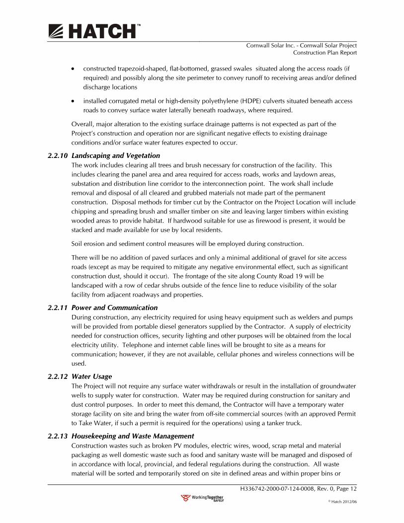
Figure 2.1 provides a conceptualized depiction of the site plan and the proposed Project facilities that are discussed throughout this report. The site plan (Figure 2.1) identifies the Project’s property boundary, the Project Location1 and facility components including the construction staging/laydown area, access roads, solar PV modules, inverters and the substation. For additional information regarding the design and operations of these components, please refer to the Design and Operations Report (Hatch Ltd., 2012a).
2.1 Construction Overview The construction process consists of four main phases:
Phase 1 – Site Preparation
Phase 2 – Construction and Installation
Phase 3 – Testing and Commissioning
Phase 4 – Site Restoration.
Table 2.1 lists the timeline and duration of the main construction activities. The initial site preparation activities are anticipated to begin in December 2012 with construction estimated to be completed by August 2013, when commercial operation is achieved. This construction scheduling is subject to change depending on a number of factors such as weather conditions, equipment delivery schedules and labour force size. Construction could range from 6 to 10 months in duration.
Table 2.1 Project Timeline
Activity Approximate Timeline Duration
Clearing, Grubbing and Stripping December 2012 30 days
Site Entrance Road(s), Power and Communications December 2012 – January 2013
15 days
Security Lighting and Entrance Fencing January – February 2013 15 days
Laydown Area and Temporary Facilities January – February 2013 15 days
Foundation Construction February – March 2013 45 days
Panel Installation April – May 2013 45 days
Electrical Collection System May – June 2013 60 days
Landscaping and Vegetation July 2013 30 days
Testing and Commissioning July 2013 30 days
In Service and Operating August 2013
1 Project Location includes the Project infrastructure footprint including lands temporally required for construction
such as vehicle parking, materials laydown and administration offices. References to the ‘site’, ‘construction site’ or ‘Project site’ are synonymous with Project Location in the context of this Report.

Cornwall Solar Inc. - Cornwall Solar Project Construction Plan Report
H336742-2000-07-124-0008, Rev. 0, Page 6
© Hatch 2012/06
2.2 Construction Methodology
2.2.1 Safety Management Safety is a primary objective for the Project. The goal is to maintain a safe working environment for workers and the public at all times. The Project will comply with all applicable Ontario Occupational Health and Safety Act (OHSA) requirements during the construction period.
The Contractor will prepare a site-specific health and safety plan, and safety and compliance will be the responsibility of the General Contractor (or their competent designated representative) to implement and strictly enforce the plan. The Contractor will provide construction method statements and related job safety assessments (JSAs) for review by the Owner’s Construction Manager, prior to commencement of work.
2.2.2 Workforce The Project will employ a workforce recruited locally, to the greatest extent possible. The workforce will include construction supervision, general and skilled labour, equipment operators, technicians for electrical systems and commissioning, plant installation and operation, security and general maintenance. The construction workforce is estimated to be 50 workers on average for the 6- to 10-month construction period, with a peak of approximately 90 workers.
Construction hours will normally be from 7:00 a.m. to 6:00 p.m., Monday through Friday, in accordance with local municipal by-laws. Occasionally, when work may have to be continued after dusk and on the weekends, the Project will follow the local municipal requirements and minimize impacts to the local community.
2.2.3 Vehicle Access A large portion of the traffic generated will be for the delivery of components and equipment during construction. Table 2.2 describes the estimated number of daily traffic trips to and from the site in each category during construction for a typical 10-MW project.
Table 2.2 Estimated Construction Traffic
Purpose
Traffic During Site Preparation
Traffic During Construction and Installation
Workers (daily roundtrips) 20 vehicles, assuming each worker drives individual vehicle
40 to 50 vehicles, assuming workers are a mixture of car pools and drive individual vehicles
Trucks Delivering Road Aggregate (daily roundtrips)
5 (25‐ton trucks) 0
Construction Vehicles (one way only)
5 vehicles 0
Deliveries (daily roundtrips) 6 to 10 vehicles 10 to 15 vehicles Substation and Switching Station Equipment Deliveries (daily roundtrips; approx. 20 total)
5 vehicles (may require wide load trucks)
Total 36 vehicles 120 vehicles

!.
G
G
G
G
G
G
G
G
G
G
C
Main SiteAccess
Laydown Area
W
oods Dra
in
12 m
27 m
115 m
115 m
12 m
EmergencySite Access
COUNTY RD 19
CO
UN
TY R
D 20
KIN
LO
CH
RD
Cornwall Solar, Inc.
Cornwall Solar ProjectSite Plan
0 100 200 30050Metres
Scale 1:5,000
N
Notes:1. Produced by Hatch under licence from Ontario Ministry of Natural Resources, Copyright (c) Queens Printer 2011.2. Spatial referencing UTM NAD 83.3. Satellite Imagery from Google Earth Pro.
Key Map
!Highway 401
HIG
HW
AY 138
CornwallSt. Lawrence River
Project Site
Date Saved: 3/7/2012 12:00:19 PM
Figure 2.1
LEGEND
Noise Receptor
Road
Watercourse
Average Annual High Water Mark
Parcel
Provincially Significant Wetland
!. Interconnection Point
G Inverter
Access Road
Laydown Area
Solar Panel
Substation
! ! Existing Distribution Line
! ! Overhead Distribution Line
Fencing
Project Location
Project Site
Trees Cleared to Remove Shading
Project Components
Path: P:\336742\SPECIALIST_APPS\Cornwall\Cornwall_Construction_Design_24Jan12.mxd

Cornwall Solar Inc. - Cornwall Solar Project Construction Plan Report
H336742-2000-07-124-0008, Rev. 0, Page 8
© Hatch 2012/06
BACK OF FIGURE

Cornwall Solar Inc. - Cornwall Solar Project Construction Plan Report
H336742-2000-07-124-0008, Rev. 0, Page 9
© Hatch 2012/06
The proposed site is approximately 7.5 km north of Highway 401 and can be accessed by County Road (County Road 19) from the east or west.
Upon reaching the site, delivery trucks will enter the main construction access road from the entrance on County Road 19, as shown in Figure 2.1. The trucks will use the on-site gravel roads, to deliver supplies to the area under construction. The trucks will exit the site at the same entrance on County Road 19. A secondary entrance will be available from County Road 19, for emergency vehicle access, as shown in Figure 2.1.
County ‘half-load’ requirements for roads will be followed during construction. The County ‘half-load’ restrictions are generally in place from mid-March to mid-May, although they can be weather dependant. Restrictions in place at the time of construction will be confirmed through consultation with the County. A flag person will direct the movement of large vehicles into and out of the site, if necessary to ensure safety and minimize impacts on traffic flow.
2.2.4 Temporary Facilities Part of the Project site will be graded and used as a construction staging/laydown area (Figure 2.1). The staging area will include construction offices, a first-aid station, worker parking, truck loading and unloading facilities, and waste disposal/pick-up area. Temporary construction trailers and portable facilities will be used for the offices and the first-aid station. Temporary toilets and washing stations will be maintained to meet the daily sanitary needs of the workforce during the construction. The staging area will be decommissioned and removed when construction is completed.
2.2.5 Construction Materials Table 2.3 lists the principal construction materials that will be transported on site for construction and the location where the material will be used and/or temporarily stored.
Table 2.3 Construction Materials
Construction Material
Delivery Vehicle and Truckloads
Usage
On-Site Storage
Concrete Transit Mixers Foundations for Electrical Building Enclosures (including Transformers, Inverters, Switchgear) and Transformer Pads
None Reinforcing Steel Semi-Trailer Laydown
Area
Lumber Semi-Trailer Formwork for Foundations Laydown Area
Steel Support Piles Semi-Trailer Foundation Supports for PV Modules Racks
Laydown Area
Granular A and B Dump Trucks 2230
Access Roads, Laydown Area, Substation Yard
None
Topsoil (if required) Dump Trucks Site Restoration of Disturbed Areas None
2.2.6 Construction Equipment Table 2.4 lists the mechanized vehicles and equipment that are expected to be used in the construction of the Project. The equipment specifications listed represent typical construction equipment that would be used to develop a solar PV facility; however, final specifications will be determined by the Contractor. The operation of this equipment has the potential to generate noise

Cornwall Solar Inc. - Cornwall Solar Project Construction Plan Report
H336742-2000-07-124-0008, Rev. 0, Page 10
© Hatch 2012/06
and air emissions (exhaust) as well as potential dust emissions resulting from earth excavation, site grading and vehicles travelling on temporary granular-based construction roads. These activities are not expected to result in significant negative effects to air quality, nearby noise receptors or wildlife as discussed in Section 3 of this Report.
Table 2.4 Typical Construction Equipment
Equipment
Power and Weight
Usage
Quantity
Track-Type Tractor (D8) 179 kW 37.6 T
Land clearing and grubbing; spreading granular material for access road
2
Wheel Tractor-Scraper (615C)
198 kW 25.6 T
Excavating and moving topsoil 1
Hydraulic Excavator (325B)
125 kW 25.9 T
Excavating topsoil and placing backfill 1 to 2
Backhoe Loader (446B) 82 kW 8.9 T
Excavating topsoil and placing backfill 1
Wheel Loader (966F) 164 kW 20.5 T
Moving soil and granular material 1
Dump Truck (D25D) 194 kW 19.5 T
Transport and placement of granular for access road
2 to 4
Motor Grader (14H) 160 kW 18.8 T
Grading of access road during construction (as necessary)
1
Drum Vibratory Compactor (CS-563C)
108 kW 10.9 T
Granular compaction for access road 1 to 2
Crawler Crane (LS-118)
267 kW 49.9 T
Pile driving or installation of screw piles (if required)
1
Pile Driving Equipment (B-6505 HD)
300 kJ 19.5 T
Mounted on the crawler crane, used for driving piles
4
Rough Terrain Crane (RT500C)
90 kW 23.4 T
Unloading and moving material and equipment
1
Telescopic Handler (TH83)
81 kW 10.0 T
Unloading and moving material and equipment
1 to 2
Concrete Transit Mixers (6 to 8-m3 Capacity)
250 kW Loaded: 20 to 25 T
Transportation and placement of concrete mix for foundations
1 to 4
Container Box and Flatbed Semi-Trailers (12 to 17 m long)
Empty: 7 to 16 T Loaded: 40 to 70 T
Transportation of tracked machines (bulldozers, excavators), large electric equipment (inverters, transformers, building enclosures) and materials (precast concrete pads, solar PV modules and support racks)
1 to 2
Pick-up Trucks (F150 Super Crew)
300 hp 2.6 T
General transportation of small equipment, materials, and personnel
5
Diesel Generators, Air Compressors
175 kW Power supply for electrical equipment (hand tools, etc)
3
Hand Tools - drills, wrenches, concrete vibrators, welding machines, saws, etc
General construction and assembly activities 15+

Cornwall Solar Inc. - Cornwall Solar Project Construction Plan Report
H336742-2000-07-124-0008, Rev. 0, Page 11
© Hatch 2012/06
Construction vehicles and some types of mechanical equipment use a variety of petroleum-based or synthetic chemicals including: fuel (diesel and gasoline) for engine combustion; lubricants (motor oils) for engine cooling and lubrication of mechanical parts; hydraulic fluids (mineral oil) for hydraulic systems such as brakes, power steering, backhoes and excavators; and, coolants (methanol, glycol blends) used in vehicle radiators and windshield antifreeze. The potential effects of accidental spills or leakage of these fluids, along with mitigation measures to prevent and/or clean-up spills, are discussed in Section 3.4.
Construction equipment will be transported to and from the Project site using public roads. Tracked vehicles such as bulldozers, excavators and large pieces of electrical equipment (e.g., inverters, transformers, building enclosures) will be transported on flatbed trailers. Wheeled vehicles such as dump trucks, concrete mixer trucks and tractor trailers will be driven directly to and from the site.
2.2.7 Fencing, Security Gate and Lighting The perimeter of the Project Location will be fenced and the main Project site entrance from County Road 19 will be gated with additional security measures installed as required. The fence will be galvanized steel chain link about 2.1 m high with barbed wire on top of the fence. Fence posts will typically be spaced every ±2.5 m. During construction, the site will be monitored by the supervising construction staff.
2.2.8 Fire Control Plan The Project is very unlikely to be a source of fire, or a contributor to the spreading of an existing fire. However, there are some very limited potential fire hazards due to electrical faults. The Contractor will be required to prepare a fire control plan, which specifies emergency response procedures for specific types of possible fires, staff training requirements and fire protection equipment that will be kept on site. This plan will be sent to the Township Fire Department for review prior to commencement of construction.
2.2.9 Drainage Maintenance of existing drainage patterns is an important part of minimizing impacts to the environment and to neighbouring properties. To the greatest extent possible, local drainage divides and flow patterns will be maintained. Soil erosion and sediment control measures will be implemented to minimize suspended solids in stormwater runoff during construction, and low-maintenance grass will be planted in disturbed areas following completion of construction to further assist in erosion control.
The specific components of the Project’s surface drainage system will be established as part of an overall drainage plan developed for the site during detailed design. In general, the surface drainage system for the Project will follow the existing drainage patterns and will consist of the following:
overland runoff (i.e., sheet flow) on grassed and vegetated areas to convey runoff from the solar PV modules
constructed shallow, triangular-shaped, grassed swales situated along the access roads to convey runoff from interior areas of the site (i.e., solar arrays)
Cornwall Solar Inc. - Cornwall Solar Project Construction Plan Report
H336742-2000-07-124-0008, Rev. 0, Page 12
© Hatch 2012/06
constructed trapezoid-shaped, flat-bottomed, grassed swales situated along the access roads (if required) and possibly along the site perimeter to convey runoff to receiving areas and/or defined discharge locations
installed corrugated metal or high-density polyethylene (HDPE) culverts situated beneath access roads to convey surface water laterally beneath roadways, where required.
Overall, major alteration to the existing surface drainage patterns is not expected as part of the Project’s construction and operation nor are significant negative effects to existing drainage conditions and/or surface water features expected to occur.
2.2.10 Landscaping and Vegetation The work includes clearing all trees and brush necessary for construction of the facility. This includes clearing the panel area and area required for access roads, works and laydown areas, substation and distribution line corridor to the interconnection point. The work shall include removal and disposal of all cleared and grubbed materials not made part of the permanent construction. Disposal methods for timber cut by the Contractor on the Project Location will include chipping and spreading brush and smaller timber on site and leaving larger timbers within existing wooded areas to provide habitat. If hardwood suitable for use as firewood is present, it would be stacked and made available for use by local residents.
Soil erosion and sediment control measures will be employed during construction.
There will be no addition of paved surfaces and only a minimal additional of gravel for site access roads (except as may be required to mitigate any negative environmental effect, such as significant construction dust, should it occur). The frontage of the site along County Road 19 will be landscaped with a row of cedar shrubs outside of the fence line to reduce visibility of the solar facility from adjacent roadways and properties.
2.2.11 Power and Communication During construction, any electricity required for using heavy equipment such as welders and pumps will be provided from portable diesel generators supplied by the Contractor. A supply of electricity needed for construction offices, security lighting and other purposes will be obtained from the local electricity utility. Telephone and internet cable lines will be brought to site as a means for communication; however, if they are not available, cellular phones and wireless connections will be used.
2.2.12 Water Usage The Project will not require any surface water withdrawals or result in the installation of groundwater wells to supply water for construction. Water may be required during construction for sanitary and dust control purposes. In order to meet this demand, the Contractor will have a temporary water storage facility on site and bring the water from off-site commercial sources (with an approved Permit to Take Water, if such a permit is required for the operations) using a tanker truck.
2.2.13 Housekeeping and Waste Management Construction wastes such as broken PV modules, electric wires, wood, scrap metal and material packaging as well domestic waste such as food and sanitary waste will be managed and disposed of in accordance with local, provincial, and federal regulations during the construction. All waste material will be sorted and temporarily stored on site in defined areas and within proper bins or

Cornwall Solar Inc. - Cornwall Solar Project Construction Plan Report
H336742-2000-07-124-0008, Rev. 0, Page 13
© Hatch 2012/06
containers as appropriate. The recyclable wastes will be returned safely to the recycle centre for further processing and reuse. Sanitary facilities on site will include portable self-contained toilets provided and maintained by the Contractor.
2.3 Construction Phases
2.3.1 Phase 1 - Site Preparation Site preparation refers to all necessary activities prior to the construction of foundations, substation, and installation of the PV modules. It includes surveying/staking, installation of erosion and sediment controls, site clearing and grubbing, surface grading, construction of access roads and drainage systems, installation of security gate and fencing, and construction of a staging area.
2.3.1.1 Site Survey and Staking A registered Ontario land surveyor will provide a site survey, and will stake the exact location of the site perimeter for fencing. The Contractor will be responsible for staking the access road layout, and all foundations and substation locations. If necessary, a locator will be hired to demarcate any buried utilities, infrastructure and their associated easements as well as any designated environmental features (e.g., woodlands, wetlands, significant wildlife habitats, etc) and their associated setbacks will be demarcated and protected by means of staking, flagging, fencing and signage to prevent any intrusion into these areas by construction vehicles.
2.3.1.2 Erosion and Sedimentation Controls Prior to any vegetation removal, clearing and/or grading activities, erosion and sedimentation control measures (e.g., silt fence barriers, rock flow check dams, etc) will be installed where required throughout the site. Additional measures will be installed as required for specific Phase 2 construction activities, discussed in Section 2.3.2. All erosion and sedimentation control measures will remain in place throughout the construction period and will be routinely inspected and maintained by the Contractor.
2.3.1.3 Construction Staging/Laydown Area Part of the Project Location will be graded and used as a construction staging/laydown area as shown in Figure 2.1. The staging area will include construction offices, washrooms, first-aid station, worker parking, construction equipment, material laydown and storage shed, truck unloading/loading area, and a waste disposal/pick-up area. Modular trailers will be used for the construction offices, washrooms and first-aid station. Washrooms (portable toilets) will be maintained during construction.
Establishment of the staging area will involve the removal of vegetation and the stripping and stockpiling of topsoil. A layer of granular material (possibly underlain by geogrid and/or geotextile) will be installed to provide an adequate road base for construction vehicles, heavy equipment and material laydown. The staging area will be decommissioned and all temporary facilities removed when construction is completed, although portions of the area may be retained to provide vehicle parking for maintenance personnel and equipment storage.
2.3.1.4 Tree Cutting and Vegetation Removal Clearing, stripping, and grubbing will be conducted using chainsaws. Stumps, roots and brush vegetation will be removed using an excavator or small bulldozer. Groundcover vegetation will be left in place to the extent possible. During the clearing activities, wood debris that is not suitable for

Cornwall Solar Inc. - Cornwall Solar Project Construction Plan Report
H336742-2000-07-124-0008, Rev. 0, Page 14
© Hatch 2012/06
use as firewood and other cleared vegetation will be either chipped and spread on site (for erosion control or landscaping purposes) or left in place to provide habitat in adjacent areas of the property.
2.3.1.5 Excavations, Fill Placement and Surface Grading The primary excavation work will be limited to soil removal for building foundation construction (Section 2.3.2.1), access road construction (Section 2.3.1.6), and digging of trenches to run electrical cables (Section 2.3.2.2). The utilization of driven piles, screw piles or ballasted foundations to support the solar PV modules (Section 2.3.2.3) may not require soil excavation. No excavations, fill placement or grading activities will take place within 115 m of a water body (i.e., the Woods Drain). Sediment and erosion control measures will be implemented for areas with exposed soils to control soil erosion caused by wind or runoff.
Once completed, foundation excavations and cable trenches will be backfilled and levelled to match the existing grade. Any excess subsoil will be used to infill low-lying areas followed by general surface grading, including redistribution of topsoil; overall, the Project is not expected to result in any excess fill material. Following this, the entire Project area, with the exception of new access roads and parking lots, will be covered with low maintenance, dense-growing vegetation. Native plant species from local sources will be used if available and suitable for use at the site.
2.3.1.6 Access Roads The Contractor shall provide access roads to all power conditioning system (PCS) nodes and the substation, as per the layout shown on the site plan. The Contractor shall review and note any constraints, and provide the final access road layout based on the detailed facility design. The minimum road grade should be 0.5%, and all roads shall have a surface width of approximately 5.0 m, plus shoulders on each side.
The width, turning radii and pavement structure (if applicable) of all access roads shall be designed to accommodate all anticipated vehicles and equipment requirements, and at a minimum should be able to accommodate a fire truck, for fire prevention purposes during operation.
Maintenance of roads and other areas shall commence immediately after commencement of the Contract and shall continue, except as otherwise required by the Owner, until completion of the Contract. The design of all access roads shall take into consideration that the roads will need to be removed when the facility is decommissioned, and the site will be returned to natural conditions.
Culverts will be installed beneath the access roads at locations where conveyance of surface drainage is required. As part of the site drainage plan, parallel side ditches may be constructed along the access roads to collect and convey runoff. Design of roads, culverts, swales, and ditches will be in accordance with local municipal engineering guidelines, where necessary. Erosion and sedimentation control measures (e.g., silt fence barriers, rock flow check dams, etc) will be installed where required.
2.3.1.7 Surface Drainage The specific details of the Project site surface drainage and any specific construction requirements will be established as part of an overall drainage plan developed for the site during detailed design. Subject to detailed design, the proposed site drainage is expected to consist of: (i) overland runoff (i.e., sheet flow) on grassed and vegetated areas; (ii) constructed shallow, triangular-shaped, grassed swales; and (iii) constructed ditches in the form of flat-bottomed, trapezoid-shaped, grassed swales

Cornwall Solar Inc. - Cornwall Solar Project Construction Plan Report
H336742-2000-07-124-0008, Rev. 0, Page 15
© Hatch 2012/06
situated along the access roads and, if required, around the perimeter of the site to intercept and convey external drainage to maintain site drainage conditions.
Construction of surface drainage features (e.g., grassed swales, ditches) would typically involve a small bulldozer to remove topsoil and form the shape of the swale and a hydraulic excavator equipped with a bucket attachment to form the shape of any ditches, followed by hydro-seeding to establish a grassed lining to protect against erosion. As necessary, riprap will be placed at locations in the ditches (e.g., culvert outfalls) to provide additional erosion protection.
Overall, major alteration to the existing surface drainage patterns is not expected as part of the Project’s construction and operation.
2.3.1.8 Building Removal The existing barn on the Project location will be removed to accommodate construction of the Project. A Demolition Permit will be obtained from the Township of South Glengarry to authorize this removal.
2.3.2 Phase 2 - Construction and Installation
2.3.2.1 Building Foundations Support foundations for the pads on which the inverters, transformers and switchgear and the substation electrical building will rest will be pre-cast or cast-in-place concrete. If pre-cast foundations are used, they will be transported to the site by truck and unloaded and set into position by crane.
If cast-in-place concrete foundations are used, they will be constructed on site by means of excavation and removal of in situ material using a backhoe or excavator, placement of granular material using a front-end loader, formwork construction, installation of reinforcing steel (rebar), installation of electrical grounding grid, and placement of concrete into the forms.
Ready-mix concrete will be delivered to the Project site by transit mixer truck from a local supplier. Foundations will require a minimum of 28 days to cure to allow for concrete to reach its specified compressive strength prior to erection of structural support and equipment installation.
A washing station will be provided on site to rinse concrete trucks prior to leaving the construction site. Water will be supplied from an off-site source and the process will use as little water as possible. The off-site source will have a valid Permit to Take Water in place from the MOE. All rinse-water will be contained and collected at the washing station, and transported off site to an approved disposal location, by an approved waste hauler.
2.3.2.2 Trenches for Cable and Instrumentation Control If permitted by the soil conditions, trenches will be excavated for electrical cabling (including DC cables from the modules to the inverters and AC cables from the inverters to the substation), unless the bedrock depth prohibits the use of trenches, in which case cable trays will be used. Trenches will typically be 1 m deep by 0.5 m wide and will be excavated using a ‘ditch-witch’ plough, or similar equipment. Trenches will have a sand base layer below and above the cabling, and once the cabling is laid, the trenches will be backfilled and levelled to match the existing grade. Where necessary, HDPE conduits will be installed beneath road crossings to house the cables in order to

Cornwall Solar Inc. - Cornwall Solar Project Construction Plan Report
H336742-2000-07-124-0008, Rev. 0, Page 16
© Hatch 2012/06
protect them. The layout of the trenches will be such that it will have minimum impact on the existing surface drainage patterns.
2.3.2.3 PV Module Mounting System, Supports and Foundations The solar PV modules will be mounted on a fixed tilt, ground-mounted racking system comprised of a steel and/or aluminum lattice structure. Each lattice structure will be assembled on site and will typically hold 24 individual PV modules. The racking system will be supported by two steel uprights mounted on either driven steel piles, steel helical screw piles, or ballasted foundations, depending on the soil conditions within the site.
Driven piles, if used, will be installed using mechanical, hydraulic or vibratory pile hammer equipment mounted on a specialized rig, excavator or boom truck. Screw piles would be installed using a similar rig, but a hydraulic drive motor would rotate the screw pile into the ground. The steel support piles will be driven or screwed to a design depth up to 3 m below grade to support the racking structure and PV modules. Compared to traditional cast-in-drilled-hole (CIDH) foundation methods, driven or screw piles do not require earth excavation, soil disposal or the use of concrete. Drilling of holes into underlying bedrock may be necessary on parts of the Project site for racking structures.
2.3.2.4 Solar PV Modules The Project will have a total of approximately 47 000 solar PV modules. The total DC capacity of the Project will be approximately 12.5 MW (10 MW AC). The solar PV modules to be used will each have a nameplate capacity of 275 to 315 watts and weigh approximately 20 to 30 kg each. The modules will be mounted on the supporting structures by installers with the help of a small mobile crane.
2.3.2.5 Electrical System The PV modules will be arranged in ten principal arrays with inverters distributed amongst each array. Each array will have a nominal AC capacity of 1 MW and be comprised of two sub-arrays, each with a nominal AC capacity of 500 kW. The modules will be strung together in strings of 8 to 14 modules. These strings will be brought to combiner boxes. From each combiner box, a single run of DC conductor will be brought to an inverter.
The Project will have a total of approximately twenty 500-kW AC inverters. These inverters will convert the DC power collected into AC power, and this will be stepped up by a transformer adjacent to each inverter to a planned voltage of 27.6 kV. The inverters and transformer will not be enclosed.
Power collection will be conducted by underground cabling, where possible depending on soil/bedrock conditions. These cables will be buried in accordance with the Ontario Electrical Safety Code. The cables will be laid in an excavated trench with a layer of sand above and below the cable, and the trench will be backfilled and levelled to match the existing grade. Caution tape will be buried in the trench above the cabling to warn anyone digging in that area of the presence of buried cables. If trenching is not possible, cable will run in aboveground conduits, in accordance with all safety requirements.
Conductors at this voltage will run underground from the inverter enclosures to the Project substation, where possible depending on soil/bedrock conditions. The main step-up transformer will

Cornwall Solar Inc. - Cornwall Solar Project Construction Plan Report
H336742-2000-07-124-0008, Rev. 0, Page 17
© Hatch 2012/06
be located in the substation, which will step the voltage up to 44-kV, the existing Hydro One 49M25 transmission line voltage.
2.3.2.6 Substation Yard and Switch House The substation yard will be located in the southeast corner of the Project Location (Figure 2.1). Construction will include excavation of topsoil, installation of ground grid, foundation construction, covering of surface area with crushed stone, and installation of electrical equipment. Switchgear, protection and control equipment will be housed in a prefabricated, weatherproof switch house building enclosure. The switch house will be trucked to the site and installed on either a precast or cast-in-place concrete pad (refer to Section 2.3.2.1). Any outdoor electrical cabinets, not housed in the switch house, will be NEMA 4X rated weatherproof cabinets.
2.3.3 Phase 3 - Testing and Commissioning Testing and commissioning will be performed on the installation prior to start-up and connection to the power grid. The solar modules, inverters, transformers and electrical cables will be checked for system continuity, reliability, and performance tested. If problems or issues are identified, modifications will be made prior to start-up.
2.3.4 Phase 4 - Site Restoration Site restoration will be applicable for the entire Project Location. The main objective will be to reinstate the area to the original pre-construction condition to the extent possible. All construction material, equipment, temporary facilities, and waste will be removed from the site. Topsoil will be redistributed where required, followed by finished grading and landscaping to achieve proper drainage. Revegetation will include planting of suitable groundcover species where required to achieve adequate vegetative coverage of disturbed areas.

Cornwall Solar Inc. - Cornwall Solar Project Construction Plan Report
H336742-2000-07-124-0008, Rev. 0, Page 18
© Hatch 2012/06
BACK OF PAGE

Cornwall Solar Inc. - Cornwall Solar Project Construction Plan Report
H336742-2000-07-124-0008, Rev. 0, Page 19
© Hatch 2012/06
3. Environmental Effects
This section of the Report identifies the potential negative environmental effects that could occur due to Project construction and documents the proposed mitigation measures to prevent or minimize negative effects.
3.1 Definition of “Environment” In order to establish potential negative environmental effects, the definition of environment must be clearly identified. For the purposes of renewable energy projects, Section 47(1) of the Environmental Protection Act defines environment as having the same meaning as in Section 1(1) of the Environmental Assessment Act. Therefore, environment means
(a) air, land or water
(b) plant and animal life, including human life
(c) the social, economic and cultural conditions that influence the life of humans or a community
(d) any building, structure, machine or other device or thing made by humans
(e) any solid, liquid, gas, odour, heat, sound, vibration or radiation resulting directly or indirectly from human activities
(f) any part or combination of the foregoing and the interrelationships between any two or more of them
in or of Ontario.
3.2 Existing Conditions Prior to completing an environmental effects assessment, an understanding of existing conditions on and within 300 m of the Project location (shown in Figure 1.1 and hereafter referred to as the “study area”), is necessary.
In order to accomplish this, Hatch gathered existing information on the study area through the following sources:
local municipalities
provincial government records, such as those maintained by the Ontario Ministry of Natural Resources (MNR), Ontario Ministry of Agriculture, Food, and Rural Affairs and the Raisin Region Conservation Authority
federal government records, such as those maintained by Natural Resources Canada, Fisheries and Oceans Canada, Environment Canada, etc
other records, such as the Atlas of the Mammals of Ontario, the Ontario Breeding Bird Atlas, etc.
Following the review of existing records, Hatch completed a number of site investigations on the property on which the Project will be located to confirm the presence of the features identified during the records review. Features identified within the study area through the records review and site investigation process provide the basis for the assessment of environmental effects associated with the construction of the Project.

Cornwall Solar Inc. - Cornwall Solar Project Construction Plan Report
H336742-2000-07-124-0008, Rev. 0, Page 20
© Hatch 2012/06
3.3 Potential Negative Environmental Effects and Mitigation Measures This section describes the potential negative environmental effects that could occur on and within 300 m of the Project location during the construction activities associated with the Project. Mitigation measures are identified to prevent potential effects from occurring, or where this is not possible, to minimize the magnitude, duration and/or footprint of the effect if it cannot be prevented. Three main categories of mitigation were considered and included where applicable:
modifying the types of construction activities
installing treatment technologies (e.g., erosion and sedimentation control measures)
changing the Project construction schedule to prevent adverse effects during sensitive time periods.
Potential environmental effects and mitigation measures are addressed by environmental component in the following sections. Accidental spills could affect a number of environmental components, but to minimize repetition, they are addressed separately in Section 3.6.
3.4 Natural Environment Components
3.4.1 Soil Quality and Quantity
3.4.1.1 Soil Erosion Surficial soils will be disturbed throughout the construction site due to vegetation removal, topsoil and subsoil stripping (where necessary), grading, use of heavy machinery and excavations. These activities have the potential to increase soil erosion due to exposure of bare soil (not protected by vegetation) to the effects of stormwater or wind.
Soil erosion has the potential to decrease the amount of soil on the Project location, which could negatively affect the ability of the soil to support vegetation growth. In addition, soil erosion could also adversely affect other environmental components, including air quality (e.g., due to dust generation), surface water quality and aquatic habitat and biota if the eroded soil is transported in or deposited in waterbodies.
Preventing erosion from occurring will be the primary goal of an erosion and sedimentation control plan, to be prepared by the construction contractor, with the prevention of off-site soil movement being the secondary goal. The main mitigation measures that will form the basis for the sediment and erosion control plan will include the following:
Erosion and sediment control measures to be placed throughout the Project site to minimize the potential for erosion and off-site sedimentation. This will include, at minimum, silt fencing installed around the Project work area. All erosion and sediment control measures are to be installed and maintained in accordance with Ontario Provincial Standards Specification (OPSS) 577.
All necessary erosion and sediment control measures must be in place prior to the start of any site disturbance, and are to remain in place until all areas of the construction site have been stabilized.

Cornwall Solar Inc. - Cornwall Solar Project Construction Plan Report
H336742-2000-07-124-0008, Rev. 0, Page 21
© Hatch 2012/06
An adequate supply of erosion control devices (e.g., geotextiles, revegetation materials) and sediment control devices (e.g., silt fences) are to be provided on site to control erosion and sedimentation and respond to unexpected events.
The size of the disturbed areas at the construction site is to be minimized to the extent possible. The extent of the work area is to be demarcated on the site to ensure that the contractor does not work beyond these bounds.
Phase construction to minimize the time that soils are exposed.
Revegetate/stabilize disturbed areas as soon as possible after exposure.
Sediment control measures will be used during any dewatering of open excavations, should they be required.
Stockpiles will have appropriate barrier/covers as necessary to prevent wind erosion.
Due to the amount of ground disturbance that will occur during construction, some erosion is likely to occur. However, with the implementation of the proposed mitigation measures as outlined above, it is anticipated that any erosion that does occur will be minor and will be localized in the Project location. No off-site movement of eroded soil is anticipated.
Erosion and sediment control measures will be regularly monitored throughout the construction period to ensure they are functioning properly and installed as per the conditions of any permits and approvals that may be issued for the Project. Measures will be remediated as necessary if deficiencies are observed during monitoring. More detail on the monitoring that will be implemented is provided in the Water Body Environmental Impact Study (EIS) (Hatch Ltd., 2012b)
3.4.1.2 Stockpiling In order to prevent mixing of topsoil and subsoils (if encountered during excavations or stripping operations), which could potential have adverse effects on the ability of the soil to support vegetation growth following re-spreading, these materials will be stockpiled separately.
Erosion of stockpiled soils due to wind or water could reduce the amount of soil available for site restoration following construction. Therefore, if necessary, temporary erosion control measures (e.g., tarping or revegetation) will be installed to prevent stockpile erosion.
Overall, stockpiling may have some negative effect on the quality of the soil in the stockpile, but implementation of these mitigation measures, to the extent possible, will minimize these potential adverse effects. Topsoil will be imported to the site for the restoration process following completion of construction, if necessary, to ensure adequate revegetation.
3.4.1.3 Soil Compaction Soil compaction (i.e., a decrease in the pore space around soil particles due to the pushing of soil particles closer together) can occur as a result of heavy equipment use, storage of heavy construction materials or stockpiling. Excessive soil compaction can result in inhibited vegetation growth by impeding root penetration within the soil, reducing aeration, and altering moisture intake (i.e., decreased infiltration due to decreased pore space within the soil structure) (DeJong-Hughes et. al., 2001). Decreased water infiltration into the soil could also potentially result in an increase in surface runoff which could increase soil erosion.

Cornwall Solar Inc. - Cornwall Solar Project Construction Plan Report
H336742-2000-07-124-0008, Rev. 0, Page 22
© Hatch 2012/06
In order to assess if soil compaction has occurred, at the completion of construction activities, disturbed areas will be visually monitored for evidence of rutting or flattened areas beneath stockpile or storage locations. Restoration efforts (e.g., discing or other soil loosening methods) will be undertaken as required to prevent significant long-term impacts due to excessive amounts of compaction. Therefore, some minor, localized compaction may be present around the Project location following construction, but any areas that would potentially have significant adverse effects on revegetation will be remediated.
3.4.2 Groundwater
3.4.2.1 Excavations into the Groundwater Table Excavations for transformer pads and potentially solar panel footings (depending on the type of footing and the installation method) could encroach on the groundwater table. These activities have the potential to cause seepage into the excavations and pumping may be necessary to keep the area dry during the construction period. If significant amounts of pumping were required, it could potentially result in lowering of the local groundwater table around the excavation. However, due to the small size of the excavations and the limited time they will be open, significant impacts on the groundwater table are not anticipated.
Should dewatering be required, all groundwater will be pumped out of the excavated area, treated, if required to meet MOE water quality discharge criteria, and discharged to a vegetated buffer area. The duration of groundwater pumping will be limited to the extent possible to avoid significant changes in the groundwater table. If groundwater seepage into excavations is extensive, other mitigation measures may be installed to prevent seepage from entering the excavations in order to avoid pumping requirements. Therefore, if pumping is required, it may result in short-term localized lowering of the groundwater table, but significant changes are not anticipated to occur.
3.4.2.2 Negative Effects on Groundwater Recharge due to Soil Compaction Soil compaction could also impact groundwater recharge by reducing water infiltration. Rehabilitation of significant areas of soil compaction following construction (as discussed in Section 3.1.1.4) will ensure that soil compaction around the site is limited with no significant adverse effects on water infiltration, and hence groundwater recharge, anticipated to occur.
3.4.2.3 Other Potential Effects on Groundwater Groundwater quality, including quality at adjacent residential wells, could potentially be adversely affected by construction activities on the Project Location, if sediments generated from or by the construction process entered the groundwater aquifer via pathways created by solar panel installation (e.g., drilling into bedrock, if necessary). This could potentially have adverse effects on well water quality.
It is anticipated that the best management practices to prevent releases of sediment will be sufficient to prevent adverse effects on groundwater during construction. However, depending on the panel installation activity requirements (e.g., type of footing and associated installation activities), other mitigation measures may be necessary.
Detailed geotechnical investigations will be conducted during the engineering design process to determine the type of footing and solar panel racking installation requirements and confirm if drilling into bedrock is necessary and if such drilling would intersect the groundwater table. If as a result of

Cornwall Solar Inc. - Cornwall Solar Project Construction Plan Report
H336742-2000-07-124-0008, Rev. 0, Page 23
© Hatch 2012/06
those geotechnical investigations it is determined that Project activities would potentially affect groundwater quality, Cornwall Solar would undertake a baseline monitoring program to characterize existing groundwater quality in residential wells adjacent to the Project Location. Cornwall Solar would work with the MOE to determine the most appropriate baseline monitoring program, based on the site specific geotechnical and groundwater conditions. Additional monitoring may be required if complaints are received from surrounding landowners regarding water well quality during construction. If this should occur, Cornwall Solar would resample the groundwater on the Project Location, and determine if adverse effects on local groundwater quality have occurred as a result of construction. If adverse effects have occurred due to construction, Cornwall Solar would implement a contingency plan, as discussed in Section 4.
3.4.3 Surface Water Quality and Quantity Surface water in the watercourse that crosses the Project site (Woods Drain) could be negatively affected during construction and installation due to the following:
turbidity from erosion/sedimentation of excavated or exposed soils
higher rates/volumes of surface water runoff due to ditching along access roads
increased turbidity from deposition of fugitive dust.
These potential effects and the mitigation measures proposed to prevent/minimize effects are discussed in the following sections.
3.4.3.1 Turbidity due to Erosion and Sedimentation Mitigation measures to prevent erosion and sedimentation from the construction site identified in Section 3.1.1.1 will be effective in preventing eroded sediment from reaching the watercourse in order to prevent adverse effects on surface water quality. The primary mitigation will be installation and monitoring of silt fencing along the edge of the Project location, which is situated 115 m from the average annual high water mark of the Woods Drain. Any sediment that does manage to pass through the silt fencing will be buffered by the heavily vegetated undisturbed areas within the 115-m setback zone, such that it should be filtered out of any surface runoff prior to discharge into the watercourse.
If dewatering of excavations is required (as discussed in Section 3.1.2.1) it will be treated, if required to meet MOE water quality discharge criteria, and discharged to a vegetated buffer area. No direct discharge to the watercourse will be permitted.
3.4.3.2 Stormwater Runoff Effects Activities that could occur during the construction phase that would have the potential to affect surface water runoff patterns and rates include the following:
land grading and ditching associated with access roads
vegetation removal.
The potential negative effects and proposed mitigation measures associated with these activities are discussed in the following sections. Soil compaction could also potentially affect surface water runoff, but given the discussion in Section 3.1.1.4, no significant adverse effects are anticipated to occur.

Cornwall Solar Inc. - Cornwall Solar Project Construction Plan Report
H336742-2000-07-124-0008, Rev. 0, Page 24
© Hatch 2012/06
3.4.3.2.1 Land Grading and Ditching The Project location consists of a mix of deciduous forest, cultural woodland, thicket and meadow communities. Localized grading will likely be required for temporary laydown areas, inverter/transformer pads and access roads and throughout the solar PV field, where necessary. This grading on the Project location may locally alter runoff patterns compared to the existing runoff from the vegetated areas. Grading will take into consideration the current land grade and will try to replicate the present stormwater flow pattern. The amount of grading conducted will be minimized to the extent possible to ensure that the topography of the Project location promotes minor stormwater retention, uptake and infiltration to minimize effects on overall runoff rates and quantity.
Drainage features including ditching and cross culverts will be required to maintain site drainage across access roads traversing the Project location. These drainage features will serve to concentrate site runoff at discharge points. Therefore, in the absence of any mitigation, surface runoff at these discharge points could potentially be at a higher rate than runoff from the existing vegetated areas. In order to mitigate potential increases in surface water runoff from the Project location, measures such as enhanced vegetated swales, flow retention features in ditches (e.g., rock-fill check dams or straw bale flow checks) and vegetated filter strips will be used to promote the retention of storm water in these features on the Project location. More information on the stormwater management measures proposed for the Project is provided in the Design and Operations Report (Hatch Ltd, 2012a). In addition to these direct storm water management features, the area beneath and around the solar panels will be planted with a densely growing ground cover to assist with slowing runoff, reducing the amount of runoff through uptake and interception and enhancing the quality of runoff by uptake of chemical constituents in the runoff. These measures will assist in mitigating any adverse effects on surface runoff from the Project location. The County and Raisin Region Conservation Authority both require that the stormwater flows from the Project site do not change as a result of the Project. Mitigation measures will be included in the detailed design to ensure that this occurs. Given this, it is not anticipated that there will be any change in the volume or general discharge patterns of stormwater runoff from the Project location to adjacent natural features, adjacent properties or the ditch along County Road 19.
3.4.3.2.2 Vegetation Removal The Project location currently consists of a mix of natural and cultural wooded area, thicket and meadow. All of the woody vegetation within the Project location, excluding the area within the setback from the watercourse, will have to be cleared. Removal of woody vegetation could decrease the amount and rate of precipitation retention on trees, water uptake by vegetation and associated evapotranspiration and therefore increase surface water runoff from the Project location. This runoff may accumulate in ditches along the Project access roads that will occupy the perimeter of much of the Project location. However, the mitigation noted in the previous section to mitigate runoff impacts in ditches, will mitigate this effect. Therefore, effects on surface water runoff from the Project location due to vegetation removal will be minimized.
3.4.3.3 Turbidity Due to Dust Deposition Mitigation to prevent fugitive dust generation from the construction site is discussed in Section 3.1.8. It is anticipated that these measures will be effective in preventing measurable effects on surface water quality due to deposition of fugitive dust from the construction site.

Cornwall Solar Inc. - Cornwall Solar Project Construction Plan Report
H336742-2000-07-124-0008, Rev. 0, Page 25
© Hatch 2012/06
3.4.4 Aquatic Habitat and Biota Solar panel installation activities will not have any direct adverse effects on aquatic habitat and/or biota since no construction will occur within 115 m of the average annual high water mark of the Woods Drain. As noted in Section 3.4.3, no significant changes in surface water runoff or surface water quality are anticipated to occur during construction, so no indirect effects on aquatic habitat or biota in the Woods Drain are anticipated to occur.
3.4.5 Vegetation
3.4.5.1 Vegetation Removal Natural vegetation will be cleared on the Project location during the construction period. This includes several types of woodland and cultural meadow/thicket vegetation communities. In order to ensure that clearing is minimized to the extent possible, the Project location will be delineated before clearing commences (through the use of caution tape, temporary fencing or silt fencing) and the construction workforce will be advised that no disturbance beyond the bounds of the demarcated area is to occur. To prevent adverse effects on residual trees adjacent to the Project location, all trees felled will be directed into the Project area. Following completion of construction, the disturbed area will be planted with a low, densely growing meadow vegetation community.
More detail on the adverse effects and mitigation measures with respect to vegetation as it applies to the Significant Natural Heritage features on and within 120 m of the Project location is provided in the Natural Heritage Environmental Impact Study (EIS) (Hatch Ltd., 2012c).
3.4.5.2 Effects Due to Dust Deposition Vegetation communities in the vicinity of the Project location may be impacted by dust deposition on leaf surfaces, resulting in minor impairment of growth. These effects are temporary in nature and will result in only short-term minor impacts to vegetation communities adjacent to the Project location. Mitigation measures to address these impacts are described in Section 3.1.8. As a result of the effective use of the mitigation measures identified in these sections, potential impacts to vegetation communities are expected to be fully mitigated, and no adverse effect is anticipated.
3.4.6 General Wildlife Communities Impacts on wildlife species could occur as a result of loss/alteration of habitat, disturbance from construction activities, or incidental mortality as a result of collision with construction vehicles.
3.4.6.1 Loss of Habitat There will be a loss/alteration of habitat throughout the Project location due to clearing of vegetation and installation of associated with the construction of the Project.
In order to minimize the potential for habitat loss, work areas will be demarcated in order to ensure that the contractor does not work beyond those bounds. Vegetation ground cover to be used on the Project site will be selected in consideration of promotion of wildlife features.
This loss of habitat will result in some wildlife species being forced to utilize habitats off the Project location. Given the amount of adjacent woodland and cultural meadow/thicket that will remain undisturbed adjacent to the Project location, no population effects on wildlife are anticipated due to habitat loss on the Project location.

Cornwall Solar Inc. - Cornwall Solar Project Construction Plan Report
H336742-2000-07-124-0008, Rev. 0, Page 26
© Hatch 2012/06
3.4.6.2 Disturbance of Wildlife Vegetation removal is currently scheduled to occur outside of the breeding bird period (generally May through July); therefore, impacts to wildlife species breeding on the Project site, such as nesting birds, are not expected to occur. If major activities, including land grading, excavations, construction of access roads, and trenching, are required during the breeding wildlife period, the areas potentially impacted will be searched by a trained biologist within 48 hours of the proposed activity in order to determine if birds are currently nesting in these areas. If nests are found, work will be suspended within 100 m of the nest location until such time as the nest is successful or abandoned. Use of these mitigation measures is anticipated to prevent potential effects to nesting wildlife.
The presence of the construction workforce and operation of construction machinery on site will result in avoidance of the Project location by species intolerant of these types of disturbances. However, given the amount of relatively undisturbed woodland habitat surrounding the Project location, it is not anticipated that such avoidance will have any adverse effects on wildlife communities.
3.4.6.3 Incidental Trapping within the Fence Line and Incidental Take The installation of the fence may trap wildlife within the Project location. Once the fence is completed, a visual search of the Project location will be conducted to search for any trapped wildlife species. If species are observed, they will be either directed off of the Project location (i.e., in the case of deer) or collected by a designated employee, who has been provided with protocols for the safe handling and transport of wildlife, and transported to the nearest available location off-site and released.
In order to minimize the potential for incidental take of wildlife, speeds on access roads of the Project site will be restricted. Further, daily visual monitoring of the project area will be completed to search for wildlife in the working area to ensure that potential impacts to these species are minimized. In addition, the construction workforce will be made aware of the potential for wildlife occurring on the Project site and that measures should be taken to avoid wildlife wherever possible. If wildlife are observed on the Project site, they will be either directed off of the Project site by the worker (without the use of vehicles) or collected by a designated employee, who has been provided with protocols for the safe handling and transport of wildlife, and transported to the nearest available location off-site and released.
Some incidental take may still occur during construction; however, levels should be negligible. Known occurrences of incidental take will be documented in the monthly environmental report. If a species at risk is noted, work within the area will be ceased immediately, and the MNR/Environment Canada (EC) will be contacted to make them aware of the occurrence. Work in the area will remain ceased until a survey is conducted by a trained biologist to ensure that there are no species at risk present in the area.
3.4.6.4 Significant Wildlife Habitat There are several Significant Wildlife Habitat features on and within 120 m of the Project location. More detail on the adverse effects and mitigation measures with respect to these significant wildlife habitat features on and within 120 m of the Project location is provided in the Natural Heritage Environmental Impact Study (EIS) (Hatch Ltd., 2012c).

Cornwall Solar Inc. - Cornwall Solar Project Construction Plan Report
H336742-2000-07-124-0008, Rev. 0, Page 27
© Hatch 2012/06
3.4.7 Species at Risk Species at risk are not included in the REA process and are dealt with under the provisions of the provincial Endangered Species Act (ESA).
3.4.7.1 Butternut Twenty-eight retainable Butternut (Juglans cineria) trees, designated as Threatened on the provincial Endangered Species Act (ESA) are located on the Project location and will require clearing to facilitate Project development. An additional six retainable Butternut trees are located within 25 m of the Project location, and although they won’t be removed, construction within 25 m of the tree has the potential to adversely affect those trees. Cornwall Solar will be required to obtain a permit under the ESA from the MNR to adversely affect a total of 34 Butternut trees. The permit will specify mitigation and monitoring, which will include planting of a number of butternut in a suitable location elsewhere on the property, combined with long-term monitoring to ensure the survival of the planted trees. Therefore, there will be a loss of Butternut on the Project location, but overall, there will be a net benefit for this species.
3.4.7.2 Bobolink Bobolink (Dolichonyx oryzivorous) are designated as Threatened on the provincial Endangered Species Act (ESA). Approximately 10.4 hectares of Bobolink habitat will be encroached upon or directly altered by the project. Cornwall Solar will be required to obtain a permit under the ESA from the MNR to alter this area. The permit will specify mitigation and monitoring, which will likely include entering into an agreement with a farmer that has hay fields and specifying that no cutting of hay be conducted before July 15 of any year to ensure that Bobolink complete nesting and the young have fledged so they are not impacted by hay cutting operations. Therefore, there will be a loss of Bobolink habitat on the Project location, but overall, there will be no net impact for this species.
3.4.7.3 Other Species Barn Swallow (Hirundo rustica), a species identified as Threatened in Ontario under the ESA, were observed on site during the site investigations and several nests were found in the residential house along County Road 19 that will remain. No long-term adverse effects on Barn Swallow nesting in the residential house, which is owned by the owners of the property on which the Project is located, are anticipated, since nesting will be able to continue and abundant fields for foraging are present in adjacent farm fields.
No other species protected by the provincial ESA or federal Species at Risk Act (SARA) were identified on the Project location.
However, a contingency plan will be developed prior to construction in order to identify procedures to be followed if a provincial or federal species at risk are identified on the Project site during construction. This will generally consist of the following:
ceasing construction activities
contacting the contractor’s environmental representative to i) confirm the presence of the species at risk, ii) identify the nature of its presence on the Project site (i.e., breeding, stop-over on migration, incidental occurrence), and iii) determine if critical habitat for the species is present

Cornwall Solar Inc. - Cornwall Solar Project Construction Plan Report
H336742-2000-07-124-0008, Rev. 0, Page 28
© Hatch 2012/06
the environmental representative will then contact MNR (for species listed on the Ontario ESA) or EC (for species listed on the federal SARA) to identify whether a mitigation plan is required, and to develop such a plan, if needed.
3.4.8 Air Quality Dust may become airborne from vehicular traffic, heavy machinery use, and soil moving activities. Dust in the air can have a range of effects including, but not limited to the following:
impacts on human health as a result of irritation to lungs, eyes, etc, which could impact construction workers or nearby residents
impacts on surface water quality and aquatic habitat if the dust is deposited into the watercourses
impacts on vegetation if heavy dust loads build up on photosynthetic surfaces, thereby resulting in mortality of the plants.
In addition to impacts from dust, a variety of construction, haulage and personnel vehicles, as well as portable generators will be used on site during the construction period. The use of this equipment will result in exhaust emissions containing, among other emissions, carbon monoxide, nitrogen oxides and sulphur oxides. Operation of this equipment will result in some minor decrease in air quality in the immediate vicinity of operating equipment, however this will be temporary in nature and emissions would be expected to dissipate following the equipment being shutdown or its movement out of the affected area.
The use of standard construction best management practices and mitigation measures, such as those identified in “Best Practices for the Reduction of Air Emissions from Construction and Demolition Activities” (Cheminfo Services Inc., 2005), will be used. These mitigation measures are to include, as required:
use of dust suppression (i.e., water or other materials that will not have adverse effects on surface water quality or vegetation growth) on exposed areas including access roads, stockpiles and work/laydown areas as necessary
hard surfacing (addition of coarse rock) of access roads or other high-traffic work areas
phased construction, where possible, to limit the amount of time soils are exposed
avoid earth-moving works during excessively wind weather. Stockpiles to be worked (e.g., loaded/unloaded) from the downwind side to minimize wind erosion
stockpiles and other disturbed areas to be stabilized as necessary (e.g., taped, mulched, graded, revegetated or watered to create a hard surface crust) to reduce/prevent erosion and escape of fugitive dust
dust curtain to be used on loaded dump trucks, delivering materials from offsite but will not be used on heavy equipment at site
workers to utilize appropriate personal protective equipment (e.g., masks, safety goggles) as necessary.

Cornwall Solar Inc. - Cornwall Solar Project Construction Plan Report
H336742-2000-07-124-0008, Rev. 0, Page 29
© Hatch 2012/06
The use of these mitigation measures would be expected to mitigate most effects of dust on local air quality, with any impacts expected to be temporary in nature.
3.5 Social Environment Components
3.5.1 Noise Construction and installation activities have the potential to result in increased noise levels on and within the vicinity of the Project location. Noise emanating from the Project site could disturb both the sensitive receptors (i.e., local residents in the vicinity) and local wildlife populations.
Construction and installation activities that produce a large amount of noise will be limited to daylight hours. Vehicles will also be regularly checked for properly working mufflers or other noise reducing equipment and all construction equipment will meet MOE emission standards (NPC 115). Construction activities will comply with the noise control by-laws of the Municipality of South Glengarry. In spite of the mitigation measures identified above, it is anticipated that noise from the Project will have some effect on local wildlife populations (addressed in Section 3.1.6.2, above) and nearby sensitive receptors. In order to minimize impacts on sensitive receptors, receptors will be made aware of a contact person for complaints relating to noise during the Project construction. As construction will occur over an approximately 6-mo or less period, the resulting effect on nearby receptors is expected to be minor and temporary, and will occur during daytime hours when effects will be reduced.
3.5.2 Traffic Increased traffic volumes and equipment delivery to the Project site and temporary disruption along routes utilized by construction vehicles may result in delays to local community traffic flow during the construction period. This potential negative effect is most likely to affect local road users in the vicinity of the Project location, as opposed to resulting in an inconvenience to a wider, regional area.
Potential negative effects as a result of increased traffic volumes and equipment delivery to the Project location as well as temporary disruption along routes utilized by construction vehicles can be minimized with the implementation of the following proposed mitigation measures:
site entrances will be appropriately located and designed in accordance with County standards to ensure appropriate turning radii are present to minimize traffic disruptions associated with large vehicles entering the site from County Road 19
additional discussions held with the County to ensure that they have input with respect to the most suitable transportation routes in order to minimize disruption
overhead lines will be temporarily removal or relocated as required (the appropriate utility will be contacted)
a police or security escort will be utilized to guide or accompany major equipment deliveries to the Project site (if required)
flagmen will be utilized as required to facilitate traffic flow and control
construction vehicles will be driven in a proper manner with respect for all traffic laws
signage providing any detour directions will be prominently displayed

Cornwall Solar Inc. - Cornwall Solar Project Construction Plan Report
H336742-2000-07-124-0008, Rev. 0, Page 30
© Hatch 2012/06
As a result, impacts to traffic will be minor, temporary, and reversible following Project construction.
3.5.3 Municipal Roadways The use of municipal roadways by construction vehicle traffic has minimal potential to result in damage to County roads, which are designed to accommodate heavy industrial vehicles. No Township roads are anticipated to be used as part of the construction vehicle access route to the Project site.
The following mitigation measures are proposed to minimize this potential negative effect:
Moving Permits (if necessary), and possibly Half-Load Restrictions (depending on the timing of construction) will be obtained prior to equipment deliveries to ensure that the County has input into the most suitable transportation routes
construction vehicles will be driven in a proper manner with respect for all traffic laws
if damage to municipal roadways does occur as a result of construction vehicles, it will be repaired as necessary during the construction period, through discussions with the County
As a result, no long-term negative effect to municipal roadways is anticipated to occur.
3.5.4 Public and Construction Site Safety Construction of the proposed development poses potential public and construction site safety concerns in the vicinity of the Project site. Potential impacts include injury from construction equipment or activities.
Implementation of the following mitigation measures will serve to minimize potential risk to public and construction staff safety within the Project site:
public access to the construction area will be prevented through the use of fences, gates, and security procedures
signage will be posted to notify the public of construction in the area
workers will be required to adhere to prescribed safety procedures
proper procedures for construction traffic will be developed, where required.
As a result the risk to public and construction site safety is effectively minimized following the use of these mitigation measures.
3.5.5 Waste Management Construction activities will likely result in the generation of recyclable material, as well as construction and sanitary waste. Generation of such material will occur within the Project location, and wastes and recyclables will be transported to the nearest, approved facility for disposal or recycling.
Solid wastes generated during construction will include construction waste such as material packaging and scrap material as well as domestic waste such as food and sanitary waste. Sanitary facilities on site will include portable self-contained toilets and washroom facilities. The following mitigation measures will serve to minimize any potential negative effects as a result of the generation of waste and recyclables:

Cornwall Solar Inc. - Cornwall Solar Project Construction Plan Report
H336742-2000-07-124-0008, Rev. 0, Page 31
© Hatch 2012/06
construction waste will be properly stored on site prior to disposal off site at local registered disposal facilities
all sanitary waste is to be contained and hauled off site by a designated hauler throughout the construction period
hazardous wastes will be properly stored in secure containers inside impervious berms or other containment areas until disposal off site at a registered facility
reuse and recycling will be practiced wherever possible
The use of these mitigation measures will minimize and environmental effects resulting from the generation of waste.
3.5.6 Land Use Lands within the Project location are zoned Rural, are classified as Class 5 agricultural land but are currently not used for any agricultural purpose. Part of the Project location was formerly used for quarrying purposes, although the timing of this use is unknown. Land use on the Project location will change once construction commences, but this is not considered to be a negative effect, since the Project location is not currently utilized for any specific purpose.
During the construction phase, there will be no adverse effects on land use within 300 m of the Project location. All of the Project construction activities will be restricted to the Project location.
3.5.7 Protected Properties No protected properties, as defined in Section 19(1) of O. Reg. 359/09, exist in the vicinity of the Project site. Therefore, no adverse effects on protected properties will occur.
3.5.8 Built Heritage and Cultural Heritage Landscapes AMICK Consultants Ltd. (2012a and 2012b) conducted a Cultural Heritage Assessment of the two separate properties on which the Project will be located. No effects on cultural heritage are anticipated to occur.
3.5.9 Archaeological Resources Stage 1 and 2 Archaeological Assessments were conducted to determine if archaeological resources were present within the Project location. The MTC has reviewed the Archaeological Assessment Report in accordance with Part VI of the Ontario Heritage Act, R.S.O. 1990, c0.18, and accepted its findings. No Archaeological resources were identified and no further archaeological investigations are required for the site. Therefore, no impacts are anticipated and no mitigation measures are proposed. However, following a standard archaeological assessment there remains a potential to uncover deeply buried heritage or archaeological resources (including human burial sites) which would not have previously been identified. In this instance, the MTC has specified mitigation that must be undertaken in the event of discovery of human remains or other archaeologically or culturally significant material:
should human remains or artifacts be identified during construction, all work in the vicinity of the discovery is to be halted immediately, as required under the Ontario Heritage Act
if human remains are found, notification is to be made to the Ontario Provincial Police (OPP), or local police who will conduct a site investigation and contact the district coroner

Cornwall Solar Inc. - Cornwall Solar Project Construction Plan Report
H336742-2000-07-124-0008, Rev. 0, Page 32
© Hatch 2012/06
notification is to be made to the Mohawk Council of Akwesasne at 613-575-2348
notification is to be made to the Ontario Ministry of Tourism and Culture and Registrar of Cemeteries, Ontario Ministry of Consumer and Commercial Relations
work is to be halted if any artifacts are found, until the site can be investigated and cleared by a licensed archaeologist.
The mitigation measures identified above will effectively minimize impacts on archaeological resources of the study area.
3.6 Potential Negative Effects Due to Accidental Spills Spills of petroleum hydrocarbon materials from vehicles/power equipment operating on site, such as fuel or hydraulic oils or spills of cement materials from cement trucks, could occur during the construction process. Spills may occur as a result of leakage from vehicles/equipment due to malfunction, leakage from storage areas (if such materials are stored on site) as a result of weakness in the storage equipment, improper handling techniques, and/or improper refuelling techniques. Spills of these materials could result in the following negative effects:
contamination of soils, surface water, and groundwater with materials inhospitable to the promotion of biological life
uptake/ingestion by, or coating of, vegetation species or terrestrial and aquatic biota resulting in senescence or individual mortality.
The extent of these effects is highly dependent on the magnitude and location of the spills (i.e., larger spills or those in proximity to sensitive areas are anticipated to potentially have greater effects). The effectiveness of the spill response has a strong bearing on the scale of potential impact.
To mitigate the potential for spills during construction, the site engineer and environmental specialist will be responsible for ensuring that the Project is constructed using best environmental management practices. The following measures will be implemented:
The General Contractor (or competent designated representative) will be appointed the responsibility for ensuring that the contractor(s) have prepared a spill clean-up procedure/emergency response plan and appropriate equipment, with all staff trained in proper implementation in the event of a spill.
Emergency contacts will be posted, including 911, Police, Fire Department, MOE Spill Centre, and contacted as required.
An emergency spill kit will be kept on site in case of fluid leaks or spills from machinery.
Establish designated refuelling and maintenance areas at least 30 m from waterbodies, drainage ditches, channels or other wet areas.
Locate designated hazardous material storage areas at least 30 m away from waterbodies for all hazardous materials to be stored outside. Storage areas should be above ground and enclosed by an impervious secondary containment structure (e.g., berm or container) capable of holding the entire volume of the stored material, as well as some additional volume of rainwater. The area should be equipped with a drain so that it can be cleared of any spilled material or

Cornwall Solar Inc. - Cornwall Solar Project Construction Plan Report
H336742-2000-07-124-0008, Rev. 0, Page 33
© Hatch 2012/06
accumulated rainwater, which would be disposed of in a suitable manner. Secondary containment areas should be monitored throughout the construction period to ensure their integrity.
Machinery is to arrive on site in a clean condition and is to be maintained free of fluid leaks.
All potentially hazardous materials, fuels and lubricants must be stored in the laydown area, in a protected/bermed area and at least 30 m from watercourses/drains.
All refuelling and equipment maintenance activities will be conducted at specified locations.
Equipment is to be monitored to ensure it is well maintained and free of leaks.
Spill containment and cleanup supplies are to be maintained on site at all times.
Spill will be cleaned up immediately and reported accordingly.
In the event of a reportable spill, the MOE Spills Action Centre (1-800-268-6060) is to be contacted immediately, as required by provincial regulations.
Portable toilets will be located no closer than 50 m from a watercourse/drain and will be pumped by an MOE approved hauler to an approved facility.
A sediment and erosion control plan will be developed and implemented.
Erosion and sediment control systems must be installed in any location where erosion or sediment from stored soil/rock piles, access roads, clearings activities, etc, could discharge directly into a surface watercourse. An adequate supply of erosion and sediment control devices (e.g., silt fences) will be maintained on site during construction.
The size of cleared and disturbed area is to be minimized where possible.
Excavated, erodible material is to be placed in suitable designated areas away from watercourses and stabilized with erosion protection.
As a result, the effective use of mitigation measures will prevent impacts on soils, groundwater, surface water, vegetation, terrestrial or aquatic biota.
3.6.1 Spills of Concrete Concrete will be used to construct the inverter and transformer pads, and depending on soil strength conditions, may also be used as ballast for the solar panel racking. Concrete will be brought on site by a ready-mix concrete supplier in concrete trucks and poured directly into the form for each transformer/inverter pad. If concrete ballast is required for the panel racking structures, it would likely consist of pre-fabricated structures brought to the site. No cement is anticipated to be stored or mixed on site.
Concrete, grout and associated materials (e.g., cement, mortars) typically have high pH values (i.e., highly basic or alkaline), which, if they enter a watercourse, could create adverse surface water quality conditions that are toxic to aquatic biota (Province of British Columbia, 2007).
Although the use of concrete during Project construction is relatively limited and will not occur within 115 m of any water body, mitigation measures are proposed to prevent negative effects. The

Cornwall Solar Inc. - Cornwall Solar Project Construction Plan Report
H336742-2000-07-124-0008, Rev. 0, Page 34
© Hatch 2012/06
Province of British Columbia (2007) has identified a number of construction best management practices to prevent adverse impacts on surface water quality and biota due to the use of concrete. Therefore, in order to mitigate potential adverse effects due to concrete and cement use, the following mitigation measures are to be implemented:
No alkaline cement products will be deposited directly or indirectly into or adjacent to any watercourse.
Concrete truck rinsing will occur at a designated area at least 120 m from any waterbodies or drainage routes in a manner to contain the rinse water and concrete residue to prevent off site transport. However, if all wastewater arising from truck rinsing will be contained and treated to meet pH requirements before discharge, then the truck rising may occur within the laydown area, however, this should be avoided if possible.
No cement is anticipated to be stored on site. However, if some cement bag storage is required, bags are to be stored indoors, where possible. If outdoor storage is required, cement bags should be covered with waterproof sheeting and raised off the ground (e.g., on wooden pallets) to ensure no contact with surface water runoff. Impervious material will be placed under the elevating mechanism to collect any spills (e.g., due to ripped bags). Empty cement bags are to be collected as soon as possible after use and spills of cement or concrete cleaned up as appropriate.
Given this mitigation, no negative effects on surface water quality due to use of concrete during construction is anticipated to occur.

Cornwall Solar Inc. - Cornwall Solar Project Construction Plan Report
H336742-2000-07-124-0008, Rev. 0, Page 35
© Hatch 2012/06
4. Environmental Effects Monitoring Plan
The Technical Bulletin for Preparing the Construction Plan Report (MOE, 2010) requires that an environmental effects monitoring plan be prepared to show how any identified negative environmental effects resulting from the Project’s construction will be mitigated and monitored to comply with O. Reg. 359/09.
As per the Technical Bulletin, the environmental effects monitoring plan for the Project construction should describe the following:
1. any negative environmental effects that may result from construction or installation activities within a 300-m radius of the activities
2. monitoring methodologies to be used
3. sampling protocols (where and when, quality assurance)
4. performance objectives used to evaluate effectiveness
5. contingency measures if monitoring reveals that negative effects are continuing to occur.
4.1 Potential Environmental Effects With respect to requirement 1 above, several Project reports in addition to this one have determined and documented the potential negative environmental effects within 300 m of the Project Location. These reports and the context of the potential negative environmental effects are as follows:
Project Description Report – potential negative environmental effects for features within 300 m of the Project during construction, operations and decommissioning.
Stage 1 & 2 Archaeological Assessment – potential negative effects to archaeological resources from construction activities.
Natural Heritage Assessment Environmental Impact Study – potential negative effects to significant natural heritage features within 120 m of the Project for construction, operation and decommissioning phases.
Water Body Environmental Impact Study – potential negative effects to waterbodies within 120 m of the Project location for construction, operation and decommissioning phases.
Based on the findings of the above-noted reports and the assessment findings of potential negative effects conducted as part of this Construction Plan, Table 4.1 provides a summary of the potential negative environmental effects due to Project construction along with proposed mitigation measures to eliminate or minimize effects such that they are not significant.
4.2 Environmental Effects Monitoring Plan Table 4.2 presents the environmental effects monitoring plan for Project construction and includes the following information:
the potential negative environmental effects, carried forward from Table 4.1, that have an ongoing risk of occurrence throughout the construction period
the performance objectives and mitigation strategies to address those effects

Cornwall Solar Inc. - Cornwall Solar Project Construction Plan Report
H336742-2000-07-124-0008, Rev. 0, Page 36
© Hatch 2012/06
monitoring protocols to confirm that performance objectives are being met, and
contingency measures in the event that objectives are not being met, as identified in the reports listed above.
The use of mitigation measures identified in Section 3 has either completely mitigated or reduced the scale of potential effects to a minor level such that quantifiable detection of residual effect(s) through specialized field measurements, sampling or laboratory analyses are not considered possible, nor necessary. Therefore, the recommended monitoring methods are based solely on qualitative, visual inspections and reporting methods to ensure compliance with the mitigation measures identified herein.
Monitoring will typically consist of weekly inspections of the Project site during construction and installation activities by an environmental representative of the Contractor or the Proponent, with reporting responsibilities directly to the Proponent. The environmental representative will ensure that all mitigation measures (e.g., sediment and erosion controls) described in this Report are in place and functioning according to design specifications. If required, repairs will be made to mitigation measures and, if necessary, remedial actions will be recommended and work ceased in the area of interest until the remedial actions are undertaken.

Cornwall Solar Inc. - Cornwall Solar Project Construction Plan Report
H336742-2000-07-124-0008, Rev. 0, Page 37
© Hatch 2012/06
Table 4.1 Summary of Potential Negative Environmental Effects and Proposed Mitigation – Construction Phase
Environmental Component Sources of Negative Effect Potential Negative Effect Mitigation Measures Residual Negative Effect
Natural Environment Components
Air Quality Vehicle and other equipment use Emissions from vehicles and other equipment could adversely affect air quality
Excessive vehicle and equipment idling will be avoided to the extent possible. Contractor will be required to have well maintained and functioning standard emissions controls on construction equipment.
Some minor, short-term, adverse effects on local air quality during construction. Emissions from operations and maintenance vehicles will be negligible.
Soil exposure and stockpiling/soil working activities during construction, aggregate-based access road/parking area use during construction
Fugitive dust emissions could adversely affect air quality
Dust control measures implemented during construction could include hard surfacing of heavily travelled areas, restrictions on soil working activities during windy conditions, stabilization of loose soil surfaces on stockpiles and watering of access roads during construction
Some short-term, adverse effects on local air quality during construction due to fugitive dust
Soil Quality Use of heavy equipment and stockpiling of heavy materials
Soil compaction affecting other environmental components (e.g., surface water drainage, groundwater recharge, vegetation growth)
Project Location will be assessed for compaction following construction. Areas of significant compaction will be remediated accordingly (e.g., through chiselling or discing).
No residual effect given effective mitigation
Soil Quantity Wind and/or water erosion of ground around the Project Location
Loss of soils from the Project Location, potentially affecting other environmental components (e.g., air quality, vegetation, surface water quality)
Sediment and erosion controls installed and maintained during construction. Drainage conveyance features with erosion protection (e.g., grass lined or other structural measures if necessary).
No residual negative effect anticipated. Mitigation will be effective in preventing erosion and sediment of soils from the Project Location.
Topsoil stripping in access road, laydown and parking areas, substation and inverter/transformer pads
Adverse effects on the quantity of topsoil and associated productivity of the soil to support vegetation growth
Stripped topsoil will be stockpiled on site for use during site restoration measures after construction
Some loss of topsoil anticipated due to stripping during construction
Groundwater Drilling for solar panel support structure racking foundations (if necessary)
Adverse effects on groundwater due to the drilling in bedrock if drilling goes into the groundwater table(requirement for drilling into bedrock to be confirmed during detailed design geotechnical investigations)
If drilling into bedrock is determined to be necessary following geotechnical investigations conducted during the detailed engineering design process, Cornwall Solar will implement a baseline groundwater quality sampling program to characterize existing water quality. If complaints regarding groundwater are provided by local residents during construction, retesting of well water quality will be implemented. If adverse effects due to the Project are determined to have occurred, remedial measures will be implemented (e.g., provision of bottled water to the effected landowners until well water quality improves).
Potential for short-term, adverse effects on groundwater quality during construction if drilling into bedrock is necessary. No residual long-term effects on groundwater quality anticipated.
Excavations for substation pad, if necessary If excavations go below the groundwater table, some pumping of groundwater out of the excavation may be necessary to keep the work area dry
Duration that pumping is required will be minimized to the extent possible. Water will either be collected and transported off site (if volumes minimal) or discharged to a heavily vegetated area with appropriate sediment and erosion controls in place.
Minor short-term change in localized groundwater table levels in area of excavation
Surface Water Quantity Changes in site topography, placement of Project components, access roads, ditches and other less pervious areas
Increase in surface water runoff affecting roadside ditches, neighbouring properties or receiving watercourse (~115 m from the Project Location)
Ditches, drainage conveyance features and stormwater management measures installed to prevent increases in surface water runoff from the Project.
No residual negative effect anticipated. Mitigation will prevent increases in the rate and/or volume of stormwater runoff from the Project Location, per County and RRCA requirements.
Surface Water Quality Wind and/or water erosion of ground around the Project Location
Erosion of soils from the Project Location could result in adverse effects on surface water quality in receiving waterbodies, with associated effects on aquatic biota and habitat
Sediment and erosion controls installed and maintained throughout construction. Drainage conveyance features with erosion protection (e.g., grass lined or other structural measures if necessary).
No residual negative effect anticipated. Mitigation will be effective in preventing erosion and sediment of soils from the Project Location.
Aquatic Habitat and Biota Erosion, increases in surface water runoff, accidental spills on Project Location
Adverse effects on aquatic habitat and biota if indirect effects occur in watercourses off the Project Location
Solar panel installation activities will not have any direct adverse effects on aquatic habitat and/or biota since no construction will occur within 115 m of the average annual high water mark of the watercourse or water bodies within the Project location.
No residual negative effects anticipated due to implementation of mitigation

Cornwall Solar Inc. - Cornwall Solar Project Construction Plan Report
H336742-2000-07-124-0008, Rev. 0, Page 38
© Hatch 2012/06
Environmental Component Sources of Negative Effect Potential Negative Effect Mitigation Measures Residual Negative Effect Woodlands Clearing of woodlands on the Project Location Clearing of vegetation within woodlands could
potentially affect the woodland form and function and its overall significance
Clearing of woodlands minimized to the extent possible on the Project Location. Northern section of the property has been avoided to maintain woodland cover. Off-site mitigation (e.g., participation in a tree planting program) will be implemented to mitigate woodland clearing.
Some decrease in size of woodland on the Project Location. No overall change in woodland significance (see Natural Heritage Assessment Reports).
Wetlands Clearing within 120 m of a Provincially Significant Wetland (PSW)
Adverse alterations in wetland form and function
A 12-m naturally vegetated undisturbed buffer will be maintained between the Project and the boundary of the wetland. This buffer, when combined with mitigation on the Project location regarding surface water quality and quantity, will prevent adverse effects on the wetland form and function.
No residual negative effects on the wetland will occur.
Removal of small isolated wetlands on the Project location, which are not part of the adjacent PSW
Adverse alterations in wetland form and function
To mitigate loss of wetlands on the Project location, wetland habitat, including pond and meadow habitat, will be created on the property northeast of the Project location (but within the property boundary).
No residual negative effects on the amount of wetland present on the property will occur, although the location of the wetlands will change.
Wildlife Habitat Presence of Project components and long-term alterations in habitat conditions on Project Location
Altered wildlife habitat use in the Project Location
Ground cover vegetation in and around the solar panel field will provide wildlife habitat for bird, reptile and small mammal species.
Wildlife use of the Project Location will be altered, but no overall change in local composition or population is anticipated to occur
Loss of small wetland ponds on the Project location providing amphibian and reptile habitat
Adverse effects on the form and function of the wetlands supporting the significant reptile habitat
To mitigate loss of wetlands on the Project location, wetland habitat, including pond and meadow habitat, will be created on the property northeast of the Project location (but within the property boundary).
No residual negative effects on the amount of wetland present on the property will occur, although the location of the wetlands will change.
Vegetation clearing, presence and use of heavy equipment and presence of workforce
Disturbance of wildlife due to noise and human presence resulting in wildlife avoidance of Project Location
Disruption of wildlife use of the Project Location and surrounding areas. Vegetation clearing will occur outside the breeding bird period where possible (typically May through early July).
Minor periodic disturbance of local wildlife. No long-term effects on species composition or local populations anticipated.
Installation of fencing Trapping of larger wildlife within the Project fence
Prior to fence completion, a visual search of the area within the fence will be completed. If species are observed, they will be directed off the Project site or collected by a designated employee using approved handling protocols.
No long-term residual effect on wildlife
Wildlife Construction vehicle travel in site access roads and throughout Project Location
Incidental take of wildlife due to construction vehicles
Speeds on access roads of the Project site will be restricted. Construction workforce alerted to the potential for wildlife and that measures should be taken to avoid wildlife wherever possible. If wildlife are observed on the Project site, they will be either directed off of the Project site by the worker (without the use of vehicles) or collected by a designated employee, who has been provided with protocols for the safe handling and transport of wildlife, and transported to the nearest available location off site and released.
Minor potential for incidental take of wildlife due to construction vehicles
Installation of fencing Trapping of larger wildlife within the Project fence
Prior to fence completion, a visual search of the area within the fence will be completed. If species are observed, they will be directed off the Project site or collected by a designated employee using approved handling protocols.
No long-term residual effect on wildlife
Noise emissions from equipment use and other construction activities (e.g., drilling)
Disturbances to nearby sensitive receptors (i.e., houses and institutions) due to noise emissions
Construction will occur in accordance with the Township’s Noise Control By-law, which restricts working hours for noise-generating activities. The Contractor will be required to have standard equipment noise muffling devices on all construction equipment operating on the site.
Construction noise will be audible during certain construction activities on the Project Location throughout the construction period

Cornwall Solar Inc. - Cornwall Solar Project Construction Plan Report
H336742-2000-07-124-0008, Rev. 0, Page 39
© Hatch 2012/06
Environmental Component Sources of Negative Effect Potential Negative Effect Mitigation Measures Residual Negative Effect
Socio-Economic Environmental Components
Noise Noise emissions from equipment use and other construction activities (e.g., drilling)
Disturbances to nearby sensitive receptors (i.e., houses and institutions) due to noise emissions
Construction will occur in accordance with the Township’s Noise Control By-law, which restricts working hours for noise-generating activities. The Contractor will be required to have standard equipment noise muffling devices on all construction equipment operating on the site.
Construction noise will be audible during certain construction activities on the Project Location throughout the construction period
Public and Facility Safety Fires or other emergency occurrences at the facility during construction
Delay in suitable response if local emergency services personnel unfamiliar with the site. Delay in access of emergency personnel if main access road is blocked.
Emergency Services personnel will be informed of the facility layout, materials and equipment present on the site, safety risks and site access procedures. Two entrances from the facility will be available for emergency personnel.
No adverse effects anticipated. Emergency Services response to emergencies on the site should not be delayed in any manner.
Presence of the Project and associated fencing None – site is on private property None required Loss of unauthorized access during life of Project
Infrastructure Heavy equipment traffic on local roads throughout construction period
Potential damage to roads due to construction traffic
Cornwall Solar will enter into an agreement with the County and Township as necessary to specific monitoring and mitigation measures required to address potential road damage. Any half-load restrictions or haul routes specified by the County/Township will be followed.
Potential short-term damage to roads during construction. No residual negative effect given effective mitigation.
Change in Visual Landscape Construction site, equipment and personnel adjacent to County Road 19, County Road 20 (Kinloch Road) and nearby residences
Portions of the facility during construction would be visible from County Road 19, County Road 20 (Kinloch Road) and from adjacent properties. This may be perceived as a negative environmental effect.
Existing vegetation along County Road 19 will be maintained the extent possible during construction to provide some visual screening during construction. Additional vegetation (cedar shrubs) will be added after construction is complete to provide a visual barrier to site.
Short-term change in local visual landscape during construction
Archaeological and Heritage Resources
Excavation of ground surface during construction
Potential for adverse effects on buried archaeological resources not observed during the Stage 2 Archaeological Assessment
If archaeological resources are observed during construction, work in the area will cease until it can be cleared by a certified archaeologist. If human remains are observed, the MTC, Police, Township, County and Aboriginal communities will be notified immediately and work will cease in the area.
No residual negative effect anticipated
Traffic Deliveries of large equipment on County Road 19
Potential delays in traffic on County Road 19 at site entrance locations due to deliveries of large equipment
Entrances will be designed to County standards with appropriate turning radii to ensure that delays associated with construction vehicles entering the site are limited.
Potential short-term disruption to traffic along County Road 19 during construction
Groundwater, Surface Water, Soil Quality, Vegetation, Biota
Accidental spills from construction vehicles/equipment
Deteriorated environmental quality due to spilled material
Spill control kits will be available on site. Spill response procedure will be implemented in the event of an accident. Staff and contractors will be trained in spill response procedure.
No residual effect given effective mitigation and spill response and clean-up measures

Cornwall Solar Inc. - Cornwall Solar Project Construction Plan Report
H336742-2000-07-124-0008, Rev. 0, Page 40
© Hatch 2012/06
Blank back

Cornwall Solar Inc. - Cornwall Solar Project Construction Plan Report
H336742-2000-07-124-0008, Rev. 0, Page 41
© Hatch 2012/06
Table 4.2 Environmental Effects Monitoring Plan – Construction
Negative Effect
Mitigation Strategy
Performance Objective
Monitoring Plan Contingency Measures Methodology Monitoring Locations Frequency Rationale Reporting Requirements
Erosion and sedimentation resulting in loss of soil and increased turbidity in site runoff
Sediment and erosion control plan with standard practices to reduce exposure of soils to wind and water erosion
No increase in soil erosion from site over and above existing conditions
Visual assessment of structural stability of sediment and erosion control mitigation measures and identification of unintended impacts (e.g., rills, gullies)
Throughout Project Location
Weekly site inspections and following major rainfall events
Visual monitoring of erosion would identify potential areas of concern
Reported in bi-weekly or monthly environmental monitoring report
Erosion remediated as necessary to ensure no erosion issues over the life of the Project.
Potential for adverse surface water, groundwater and soil quality due to accidental spills
Standard mitigation to prevent spills and minimize magnitude of spills that do occur
No long-term environmental effects due to spills
Visual monitoring of construction areas (e.g. refuelling, parking, equipment storage) and spills reporting would identify potential areas of concern
Throughout Project Location
Weekly site inspections, during any on-site refuelling or handling of toxic liquids and immediately following any reported spills
Visual monitoring of construction areas would identify potential areas of concern
Reported in bi-weekly or monthly environmental monitoring report
Spill contingency measures implemented as necessary in the event of a spill. Following spill event, response will be reviewed to determine if additional or altered response protocols are necessary to meet performance objectives.
Incidental take of wildlife
Daily visual monitoring of work areas and construction equipment prior to start of work. Wildlife observed will be removed from areas of impact through established protocols. Speeds to be limited on Project Location and construction workforce to be made aware of potential for wildlife on the Project Location.
Avoid occurrences of incidental take
Daily visual monitoring will be conducted by workers on foot of the areas to be worked on the given day. Any wildlife observed will be either directed off of the Project Location or collected by a designated employee and transported to the nearest available location off site and released.
Throughout Project Location
Ongoing during construction on a continual basis
Incidental take will be reported by construction workforce to the on-site personnel responsible for environmental protection if incidents occur
Reported in bi-weekly or monthly environmental monitoring report, unless the species is a species of conservation concern in which case reporting will be immediate to the MNR/EC
If incidental take of species of conservation concern are recorded, work will be ceased until such time as a trained biologist can state that the species is no longer present in the area
Dust generation and off-site transport
Standard construction site best management practices to prevent fugitive dust
Minimize fugitive dust from the construction site
Visual monitoring of visible dust plumes during construction
Throughout construction site
Periodically during all construction activities
Visual dust monitoring would identify if dust plumes are an issue and where their source may be
Reported in bi-weekly or monthly environmental monitoring report
Dust control measures implemented as necessary to prevent/minimize dust generation
Noise levels disturbing nearby noise receptors
Adherence to Noise Control By-Law. Proper mufflers on construction vehicles. Notification to adjacent noise receptors and call number to report noise complaints.
To minimize excessive noise emissions at nearby noise receptors
Ongoing dialogue with adjacent noise receptors and follow-up response to noise complaints
Throughout construction site with emphasis at the closest sensitive noise receptors
Ongoing during construction on a continual basis
Auditory monitoring and feedback from nearby noise receptors will confirm that noise emissions are within reasonable levels
Reported in bi-weekly or monthly environmental monitoring report
A complaints monitoring resolution process will be in place to assess contingency measure requirements

Cornwall Solar Inc. - Cornwall Solar Project Construction Plan Report
H336742-2000-07-124-0008, Rev. 0, Page 42
© Hatch 2012/06
Negative Effect
Mitigation Strategy
Performance Objective
Monitoring Plan Contingency Measures Methodology Monitoring Locations Frequency Rationale Reporting Requirements
Personal injury to public if trespassing on site or construction workers due to accidents
Public access to site will be prevented by fences, gates and security procedures. Proper health and safety procedures for construction workers.
Elimination of risk of personal injury to public and workers due to accidents or mishaps
Site security monitoring will be ongoing to confirm adequacy of security measures. Implementation of Contractor’s health and safety procedures for worker safety.
Throughout the Project Location and facility perimeter
Ongoing during construction on a continual basis
Site security monitoring will identify any breech in facility security. Contractor’s safety inspections and accident reporting with identify unsafe working practices.
Incidents of trespassing or vandalism will be reported to local authorities
Additional security measures will be implemented as required. Unsafe working areas and/or practices will be identified and corrected by the Contractor.

Cornwall Solar Inc. - Cornwall Solar Project Construction Plan Report
H336742-2000-07-124-0008, Rev. 0, Page 43
© Hatch 2012/06
5. References
AMICK Consultants Ltd. 2012a. Revised Cultural Heritage Assessment of the Cornwall A Solar Farm. Prepared for Mann Engineering Ltd.
AMICK Consultants Ltd. 2012b. Revised Cultural Heritage Resource Built Heritage and Cultural Heritage Landscapes. Prepared for Hatch Ltd.
Cheminfo Services Inc. 2005. Best Practices for the Reduction of Air Emissions From Construction and Demolition Activities. Prepared in conjunction with the Construction and Demolition Multi-Stakeholder Working Group for Environment Canada, Transboundary Issues Branch. 49 pp.
Hatch Ltd. 2012a. Cornwall Solar Project – Design and Operations Report. Prepared for Cornwall Solar Inc.
Hatch Ltd. 2012b. Cornwall Solar Project – Water Body Environmental Impact Study. Prepared for Cornwall Solar Inc.
Hatch Ltd. 2012c. Cornwall Solar Project – Natural Heritage Environmental Impact Study. Prepared for Cornwall Solar Inc.
Hatch Ltd. 2012e. Cornwall Solar Project – Approval and Permitting Requirement. Prepared for Cornwall Solar Inc.
Ministry of the Environment (MOE). 2011. Technical Guide to Renewable Energy Approvals. Queen’s Printer for Ontario. 199 pp.
MOE. 2010. Technical Bulletin Three – Guidance for preparing the Construction Plan Report as part of an application under O. Reg. 359/09. Draft document posted for public comment on the Environmental Registry March 1, 2010. Queen’s Printer for Ontario. 14 pp.
Government of Ontario. 2009. Ontario Regulation 359/09 made under the Environmental Protection Act 2007, Renewable Energy Approvals under Part V.0.1. of the Act. September 8, 2009 version. Printed in the Ontario Gazette: October 10, 2009. Available on-line at: http://www.elaws.gov.on.ca/html/source/regs/english/2009/elaws_src_regs_r09359)e.htm.
Government of Ontario. 2010. Ontario Regulation 521/10 made under the Environmental Protection Act, Renewable Energy Approvals under Part V.0.1 of the Act. December 15, 2010 version. Printed in The Ontario Gazette: January 8, 2011. Available on-line at: http://www.elaws.gov.on.ca/html/source/regs/english/2010/elaws_src_regs_r10521_e.htm.