Embed Size (px)
Citation preview

SOLAR ENERGY MONITORING SYSTEM
NURULHUDA BINTI NGASIMAN
This thesis is submitted as partial fulfillment of the requirements for the award of the
Bachelor of Electrical Engineering (Hons.) (Electronics)
Faculty of Electrical & Electronics Engineering
Universiti Malaysia Pahang
APRIL, 2009

iv
ACKNOWLEDGEMENT
I would like to express my gratitude to Allah with His permission I am done
with my project and it ran smoothly and successfully. Alhamdulillah, His
Willingness has made it possible for me as the author to complete the final year
project in time.
I would like to take this opportunity to give my special thanks to my
dedicated supervisor, Mr Mohd Shawal Bin Jadin for guiding this project at every
stage with clarity, spending much time to discuss and help with this project, and that
priceless gift of getting things done by sharing his valuable ideas as well as share his
knowledge.
I would also like to thank to all UMP lecturers and electrical technicians
whom had helped directly or indirectly in what so ever manner thus making this
project a reality.
Not forgotten are my best colleagues for their openhandedly and kindly
guided, assisted, supported and encouraged me to make this project successful. My
heartfelt thanks to my dearest family which always support and pray on me
throughout this project. Their blessing gave me the high-spirit and strength to face
any problem occurred and to overcome them rightly.
The great cooperation, kindheartedness and readiness to share worth
experiences that have been shown by them will be always appreciated and treasured
by me, thank you.

v
ABSTRACT
Solar energy is energy from the sun. This energy drives the climate and
weather and supports virtually all life on Earth. Heat and light from sun, along with
solar based resources such as wind and wave power, hydroelectricity and biomass,
account for most the available flow of renewable energy. Solar power is becoming
increasingly popular, as environment friendly renewable energy source that produces
no pollution, requires minimal maintenance and energy from the sun is free. There
many technologies for solar energy application through the residential, commercial,
industrial, agricultural, and transportation sectors. The solar energy wide variety of
technologies is flexibility. One types of Solar Energy system is Solar Photovoltaic
Power. Photovoltaic Standalone system, Photovoltaic Hybrid system, Photovoltaic
Grid Tie system is types of Solar Photovoltaic Power. Photovoltaic system use cell
to convert sunlight into electricity. The PV cells consist of one or two layer of a
semi conducting material, usually silicon. When light shines on the cell it creates an
electric field across the layers causing electricity flow. So, the greater intensity of
the light, the greater electricity flows. PV cells are referred to in terms of the amount
of energy they generate in full sunlight; know as kilowatt peak or kWP. This project
is to design a Solar Energy Monitoring System. The system use LCD to display as
the meter to view that measurement of voltage and current in the system. The design
uses a PIC microcontroller (PIC 16F877) as control unit and optimizes the use of
feature that exist in PIC microcontroller such as analogue to digital converter (ADC).
Then to design a signal conditioning circuit, which is, consist of transducers (voltage
sensor and current sensor).

vi
ABSTRAK
Tenaga Suria adalah tenaga dari matahari. Tenaga suria ini dibawa oleh iklim,
cuaca dan menyokong segala kehidupan di bumi. Tenaga Haba dan cahaya dari
matahari, berserta sumber-sumber semulajadi suria seperti angin dan tenaga
gelombang, tenaga hidroelektrik and tenaga biojisim. adalah tenaga yang ada serta
boleh diperbaharui. Tenaga Suria adalah tenaga yang sedang meningkat popular,
sebagai tenaga sumber mesra alam yang tidak mengeluarkan pencemaran alam,
memerlukan penyelengaran yang rendah dan sumber tenaga matahari percuma dan
berterusan. Sekarang ini banyak teknologi digunakan untuk Tenaga Suria telah
diaplikasi di rumah, komersial, industri, pertanian, dan sektor pengangkutan.
Teknologi Tenaga Suria adalah sangat luas and mudah berubah-rubah. Salah satu
teknologi sistem suria adalah Tenaga Suria Fotovolta (PV). Suria Fotovolta
mempuyai beberape jenis iaitu Sistem Fotovolta berdiri sendiri,Sistem Hibrid
Fotovolta dan Sistem Grid Tie Fotovolta. Sistem Fotovolta (PV) adalah
menggunakan sel untuk menukarkan cahaya matahari kepada tenaga elektrik. Sel PV
mengandungi satu atau dua lapisan bahan semi konduktor yang biasanya seperti
silikon. Sinaran cahaya matahari pada permukaan sel akan meghasilkan persilangan
lapisan medan elektrik disebabkan oleh pengaliran elektrik. Semakin kuat keamatan
cahaya matahari, semakin banyak pengaliran elektrik. Sel PV adalah merujuk kepada
jumlah penuh tenaga yang dihasilkan oleh cahaya matahari seperti puncak kilowatt
atau kWp. Sistem Pemaparan Tenaga Suria ini telah direka untuk Sistem Fotovolta
berdiri sendiri. Sistem ini mengunakan LCD sebagai meter untuk memaparkan
pengukuran atau sukatan voltan dan aliran arus elektrik dalam sistem Fotovolta.
Sistem ini juga direka menggunakan PIC micro kawalan (PIC 16F877) sebagai unit
kawalan dan optimis menggunakan ciri-ciri yang ada di dalam PIC micro kawalan
seperti penukaran signal analog kepada signal digital. Selain itu, menghasilkan
penyesuaian litar dimana mengandungi sensor (voltan sensor dan arus sensor).

vii
TABLE OF CONTENTS
CHAPTER TITLE PAGE
DECLARATION ii
DEDICATION iii
ACKNOWLEDGEMENT iv
ABSTRACT v
ABSTRAK vi
TABLE OF CONTENTS vii
LIST OF TABLES xi
LIST OF FIGURES xii
LIST OF SYMBOLS xvi
LIST OF ABBREVIATIONS xvii
LIST OF APPENDICES xviii
1 INTRODUCTION 1
1.1 Background 1
1.2 Introduction to the Project 1
1.3 Problem Statement 3
1.4 Objective 4
1.5 Scope of Project 4
1.6 Thesis Overview 5
viii
TABLE OF CONTENTS
CHAPTER TITLE PAGE
2 LITERATURE REVIEW 6
2.1 User Monitoring System 6
2.2 Analog Circuit 8
2.3 PICBASIC Language 16
3 METHODOLOGY 17
3.1 Project Methodology 17
3.2 System’s Flow 18
3.3 System’s Diagram 20
4 SYSTEM’S ARCHITECTURE 22
4.1 Hardware Design 22
4.1.1 Power Supply Module 25
4.1.2 PIC Module 25
4.1.3 LCD Display and Switches 26
4.1.4 Sensor Module with PIC 28
4.2 Software Implementation 31
4.2.1 Microcode Studio 31
ix
TABLE OF CONTENTS
CHAPTER TITLE PAGE
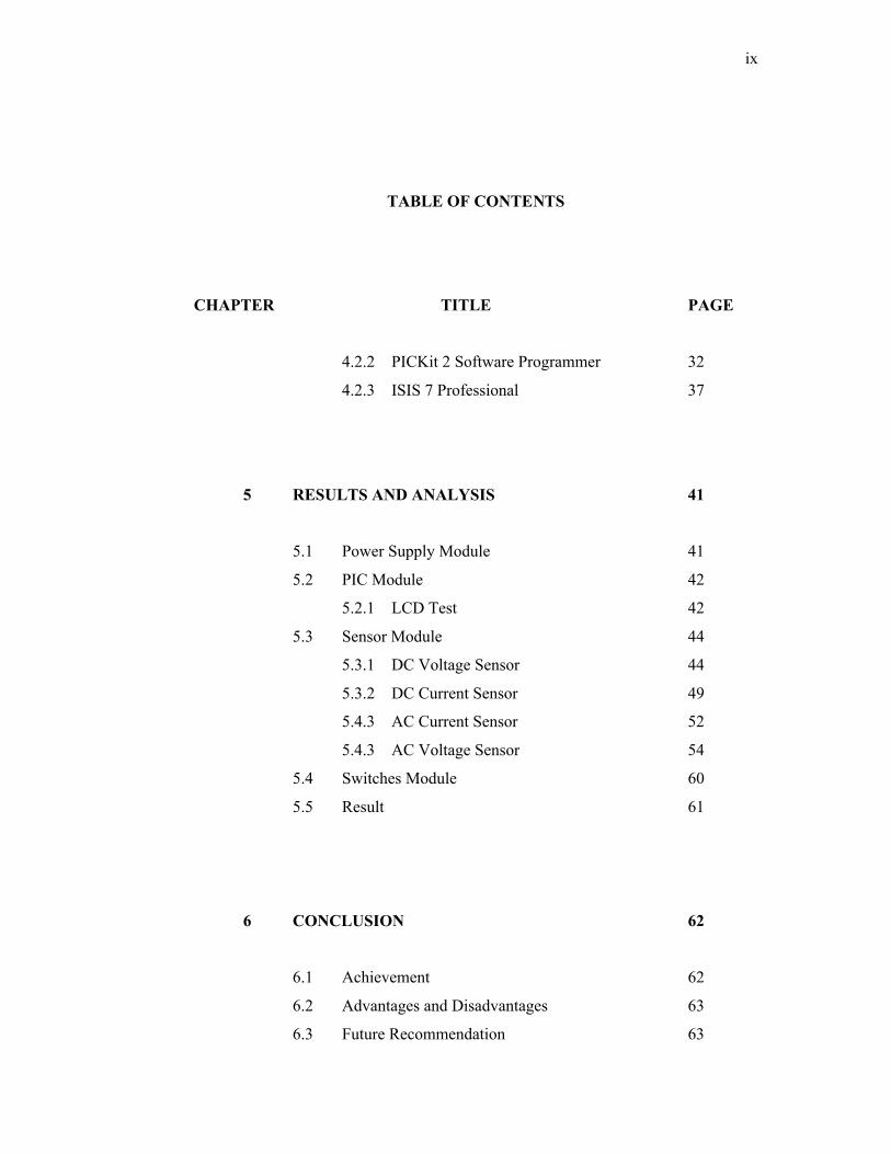
4.2.2 PICKit 2 Software Programmer 32
4.2.3 ISIS 7 Professional 37
5 RESULTS AND ANALYSIS 41
5.1 Power Supply Module 41
5.2 PIC Module 42
5.2.1 LCD Test 42
5.3 Sensor Module 44
5.3.1 DC Voltage Sensor 44
5.3.2 DC Current Sensor 49
5.4.3 AC Current Sensor 52
5.4.3 AC Voltage Sensor 54
5.4 Switches Module 60
5.5 Result 61
6 CONCLUSION 62
6.1 Achievement 62
6.2 Advantages and Disadvantages 63
6.3 Future Recommendation 63

x
TABLE OF CONTENTS
CHAPTER TITLE PAGE
6.4 Cost and Commercialization 64
REFERENCES 66
APPENDICES A - F 67 – 89
xi
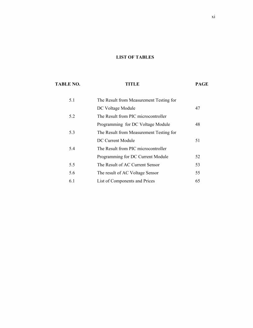
LIST OF TABLES
TABLE NO. TITLE PAGE
5.1 The Result from Measurement Testing for
DC Voltage Module 47
5.2 The Result from PIC microcontroller
Programming for DC Voltage Module 48
5.3 The Result from Measurement Testing for
DC Current Module 51
5.4 The Result from PIC microcontroller
Programming for DC Current Module 52
5.5 The Result of AC Current Sensor 53
5.6 The result of AC Voltage Sensor 55
6.1 List of Components and Prices 65

xii
LIST OF FIGURES
FIGURES NO. TITLE PAGE
1.1 Photovoltaic Standalone System 2
1.2 Photovoltaic Hybrid System 2
1.3 Photovoltaic Grid Tie System 3
1.4 Block Diagram for Photovoltaic
Standalone System 3
2.1 Photovoltaic cell 9
2.2 Photovoltaic Module 9
2.3 Power Inverter 10
2.4 Register of ADC PIC 16F877 12
2.5 Pins Diagram PIC 16F877 13
2.6 Bridge Rectifier: A full Wave Rectifier
Using Four Diode 14
2.7 Current Sensor IC (ACS 712) 16
2.8 ACS 712 Pins Configuration and Connection 16
3.1 Developing the Solar Energy Monitoring
System 18
3.2 Flowcharts on Solar Energy Monitoring System 20
3.3 Block Diagram of Photovoltaic Standalone
System 21
4.1 The Components in Photovoltaic Standalone
System 23
4.2 The Full Diagram of Solar Energy Monitoring 24
System
4.3 Full Schematic Diagram 25
4.4 Power Module Circuit Diagram 25

xiii
LIST OF FIGURES
FIGURES NO. TITLE PAGE
4.5 Circuit Diagram for PIC Module 26
4.6 Schematic for LCD Display and Switches 27
4.7 LCD Display and Switches Layout 27
4.8 Voltage Divider Circuits at DC Side
As a Voltage Sensor 28
4.9 The Current Sensor at DC Side 29
4.10 The Current Sensor at AC Side 29
4.11 Voltage Transformer with Peak Detector Circuit
As a Voltage Sensor at AC Side 30
4.12 Board Layout for the Solar Energy Monitoring
System 30
4.13 Compile the Program 32
4.14 Device Family Selection 33
4.15 Midrange Device Family for PIC16F877 33
4.16 Import Hex File and Write Device Button 34
4.17 Import Hex File Dialogue Box 35
4.18 Download Program Progress 35
4.19 File Update Notification 36
4.20 The Location of the Button on the Programmer
Hardware 36
4.21 The success Downloading Process Notification 37
4.22 Edit Properties for PIC Microcontroller 38
4.23 Program File 39
4.24 File Selection 39
4.25 PIC Microcontroller Display the Data 40

xiv
LIST OF FIGURES
FIGURES NO. TITLE PAGE
5.1 Power Supply Module 41
5.2 LCD Testing Program 43
5.3 LCD Test 43
5.4 PIC Microcontroller Programming to
Access ADC 44
5.5 The DC Voltage Sensor Hardware 45
5.6 DC Voltage Sensor Testing 46
5.7 PIC Microcontrollers Programming
for DC Voltage Sensor 46
5.8 The DC Current Sensor Testing 49
5.9 The DC Current Sensor Hardware 50
5.10 PIC Microcontroller Programming
For AC Voltage Sensor 50
5.11 The AC current sensor hardware 53
5.12 PIC Microcontroller Programming for
AC Current Sensor 54
5.13 PIC Microcontroller Programming for
AC Voltage Sensor 55
5.14 AC Voltage sensor Modules 56
5.15 The Input Waveform Step Down Transformer
By Supplying Plug 57
5.16 The Output Waveform after Bridge Rectifier57
5.17 The output waveform after peak detector circuit 58
5.18 The Output Waveform Step Down Transformer
By Power Inverter Supplied 58

xv
LIST OF FIGURES
FIGURES NO. TITLE PAGE
5.19 The Output Waveform after Bridge
Rectifier (Power Inverter Supplied) 59
5.20 The Output Waveform after Peak Detector
Circuit (Power Inverter Supplied) 59
5.21 Switches Module 60
xvi
LIST OF SYMBOLS
F Farad
G Giga
Hz Hertz
M Mega
p Piko
V Volts
VDC Volts Direct Current
Ω Ohm
xvii
LIST OF ABBREVIATIONS
ADC Analog to Digital
PC Personal Computer
BASIC Beginners All Purpose Symbolic Instruction Code
AC Alternate Current
DC Direct Current
DAC Digital to Analog
EEPROM Electrically Erasable Programmable Read-Only Memory
I/O Input Output
LCD Liquid Crystal Display
PIC Peripheral Interface Controller
RAM Random Access Memory

xviii
LIST OF APPENDIXES
APPENDIXES TITLE PAGE
A Solar Energy Monitoring System Programming 67
B Circuit Schematic of Solar Energy Monitoring
System 70
C PIC 16F877 Datasheet 72
D ACS 712 Datasheet 82
E Power Inverter Datasheet 86
F Photovoltaic Datasheet 88

CHAPTER 1
INTRODUCTION
1.1 Background
The Solar Energy Monitoring System is a system which is developed using
sensor and microcontroller technology to display the exact value of solar system.
The system is separated into two parts are Solar Photovoltaic System and Solar
Energy Monitoring System. This thesis will concentrate more on Solar Energy
Monitoring. The sensor circuit is important part at dc and ac side to sense the signal
to PIC microcontroller (ADC) and reading the signal by using some command which
is programmed into PIC microcontroller. The device has liquid crystal display
(LCD) with connect to switches to getting some value parameter programmed in PIC
microcontroller by selecting switch.
1.2 Introduction to the Project
The solar energy has many technologies types that can build. Among of that
are electricity generation. The electricity generation has three ways are photovoltaic;
concentrating solar and experimental solar power. The Photovoltaics (PV) has been
mainly developed for small and medium-sized applications, from the calculator

2
powered by a single solar cell to the PV power planet. The Photovoltaic Power
System has three types are Photovoltaic Standalone system, Photovoltaic hybrid
system and Photovoltaic Grid Tie system. The Figures 1.1, Figure 1.2 and Figure 1.3
below show the types of Photovoltaic system. But the system use Photovoltaic
standalone system because time for implement are faster than a replacement system,
the cost is much less expensive to develop, implement and operate. The Figure 1.4
shown
In this project, master device used PIC Microcontroller to interface with the
Sensor module. The program for it has been written using PICBASIC language.
Microcode Studio is used to write and compile the program while PICkit 2 v2.40
programmer is used to program the PIC16F877.
Figure 1.1 Photovoltaic Standalone System
Figure 1.2 Photovoltaic Hybrid Systems
3
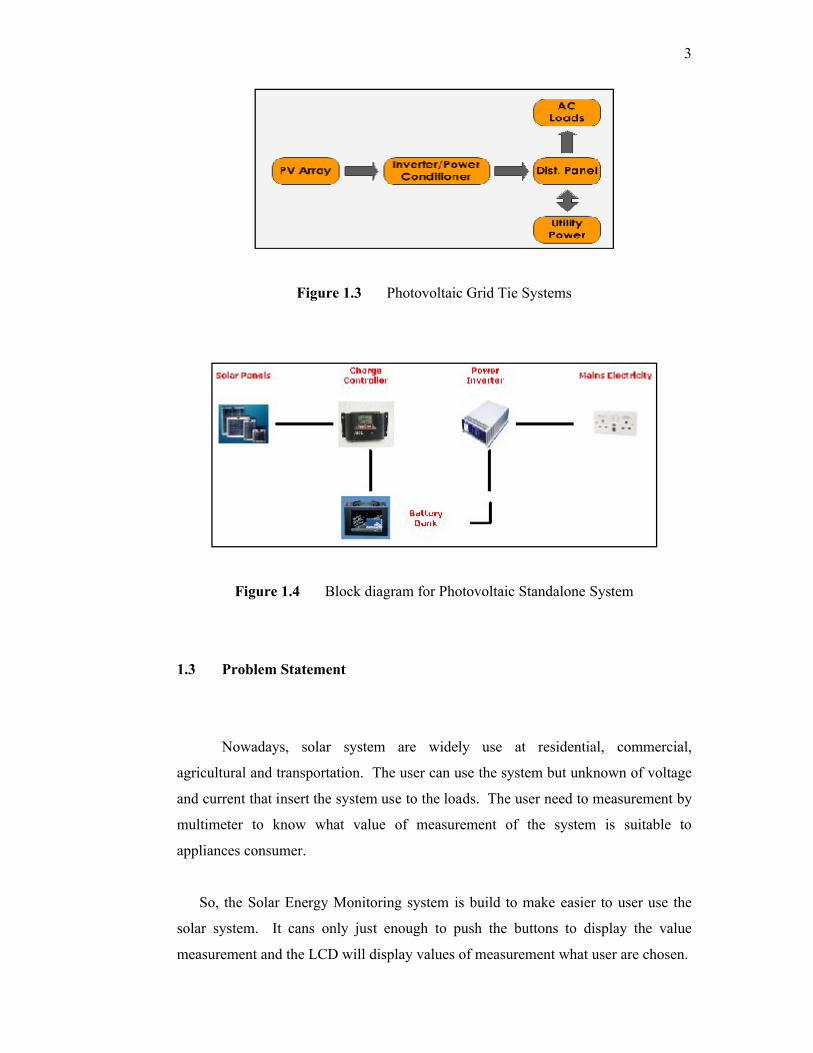
Figure 1.3 Photovoltaic Grid Tie Systems
Figure 1.4 Block diagram for Photovoltaic Standalone System
1.3 Problem Statement
Nowadays, solar system are widely use at residential, commercial,
agricultural and transportation. The user can use the system but unknown of voltage
and current that insert the system use to the loads. The user need to measurement by
multimeter to know what value of measurement of the system is suitable to
appliances consumer.
So, the Solar Energy Monitoring system is build to make easier to user use the
solar system. It cans only just enough to push the buttons to display the value
measurement and the LCD will display values of measurement what user are chosen.

4
1.4 Objectives
The objective of this project is:
(i) To develop Solar Energy Monitoring for photovoltaic standalone system
1.5 Scope of Project
This Solar Energy Monitoring system which is specifically has three scopes.
(i) Design a signal conditioning circuit; this is consisting of transducer
(voltage sensor and current sensor). - The signal conditioning circuit is a
circuit interface to microcontroller (PIC 16F877) read for obtain suitable
value at DC and AC side between 0 to 5 volts using sensor.
(ii) Design a microcontroller PIC16F877 as control unit and optimize the use
of feature that exists in microcontroller such as analogue to digital
converter (ADC). - The main components such as PIC microcontroller,
analog to digital converter (ADC) that have available in PIC16F877,
Analogue to Digital (ADC) will convert the exact value from sensor to
sense to PIC16F877 betweens 0 to 5 volt.
(iii) Design LCD display as a meter to view measurement of voltage, and
current. - The display in this system contains LCD and switches to
indicate the value of voltage and current at dc and ac side.

5
1.6 Thesis Overview
This Solar Energy Monitoring System final thesis is a combination of 6
chapters that contains and elaborates specific topics such as the Introduction,
Literature Review, Methodology, Architecture, Result and Analysis, Conclusion and
Further Development that can be applied in this project.
Chapter 1: Basically about the introduction of this project.
Chapter 2: Describe about the literature review for the development of the Solar
Energy Monitoring System.
Chapter 3: Discuss on the full methodology of this project.
Chapter 4: Discuss about the architecture of the project that consist the hardware
design and the software implementation.
Chapter 5: Discuss all the results obtained and the limitation of the project. All
discussions are concentrating on the result and performance of the
Solar Energy Monitoring System
Chapter 6: Discuss the conclusion and further development of the project.

CHAPTER 2
LITERATURE REVIEW
This chapter reviews about the study that have been done before developed
the Solar Energy System. Some of them are about the systems that are look alike this
Solar Energy Monitoring System. Other, they are the study about the main
components used.
2.1 User Monitoring System
There's another aspect of the Rockies' scoreboard, affectionately referred
to as the "Rock pile," that provides valuable information, though of a different
variety. The solar panels that power the Rock pile 46 panels in all, rated at just
under 10 kW are connected to an Internet-enabled energy metering and
monitoring system that shows the fans, in real time, how much power is being
produced by the panels and how much pollution has been prevented through the
use of this clean, renewable source of energy (Chris Beekhuis, Fat Spaniel
Technologies, June 11, 2007)[1]
From the article above published on June 11, 2007 by Chris Beekhuis, Fat
Spaniel Technologies, the User Monitoring System is a proposed system to consists
are three principal benefits of keeping score for a solar electric power system, the

7
most glamorous. A user interface linked to a power system-whether it's a solar panel
system, small-scale wind or other clean energy source-helps remind energy
consumers that their decision to purchase renewable energy is having an immediate
and measurable impact.
The second benefit of renewable user energy monitoring services is data
collection for service, maintenance and performance tuning. By capturing and
storing real-time and historic information about energy production and consumption,
system component health, and local environmental variables, an independent, user
monitoring service can provide instant, data-rich likes how much power is a system
generating and are the components functioning properly, or has there been a failure.
Monitoring helps notify system installers and distributed utilities instantly when
something goes wrong, enabling quick and easy repair. A well-designed monitoring
system can turn renewable energy system performance data into usable information
that can be presented on the monitor.
The third benefit offered by independent system monitoring is transparency.
The best way to track a system's real energy output to ensure accurate Performance
Based Incentive payments, protect ratepayer investments in capacity-based or
expected performance-based rebate programs, and to grow vibrant and trusted
financial markets for Renewable Energy Credits and Carbon Credits, is through
independent metering and monitoring. In fact, a fundamental economic tenet is that
markets don't function at all without meaningful, verifiable information that comes
from trusted sources. As renewable energy steps up to the plate to tackle the twin
problems of energy consumption and global warming, independent metering and
monitoring.
8
2.2 Analog Circuit
Under this analog circuit, most and electronic component will be discussed.
It consists of
(i) Solar Photovoltaic
(ii) Power Inverter
(iii) Microcontroller PIC 16F877
(iv) Voltage Transformer
(v) Bridge Rectifier
(vi) Current Sensor
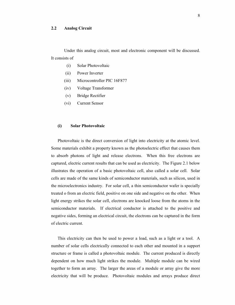
(i) Solar Photovoltaic
Photovoltaic is the direct conversion of light into electricity at the atomic level.
Some materials exhibit a property known as the photoelectric effect that causes them
to absorb photons of light and release electrons. When this free electrons are
captured, electric current results that can be used as electricity. The Figure 2.1 below
illustrates the operation of a basic photovoltaic cell, also called a solar cell. Solar
cells are made of the same kinds of semiconductor materials, such as silicon, used in
the microelectronics industry. For solar cell, a thin semiconductor wafer is specially
treated o from an electric field, positive on one side and negative on the other. When
light energy strikes the solar cell, electrons are knocked loose from the atoms in the
semiconductor materials. If electrical conductor is attached to the positive and
negative sides, forming an electrical circuit, the electrons can be captured in the form
of electric current.
This electricity can then be used to power a load, such as a light or a tool. A
number of solar cells electrically connected to each other and mounted in a support
structure or frame is called a photovoltaic module. The current produced is directly
dependent on how much light strikes the module. Multiple module can be wired
together to form an array. The larger the areas of a module or array give the more
electricity that will be produce. Photovoltaic modules and arrays produce direct