Embed Size (px)
Citation preview
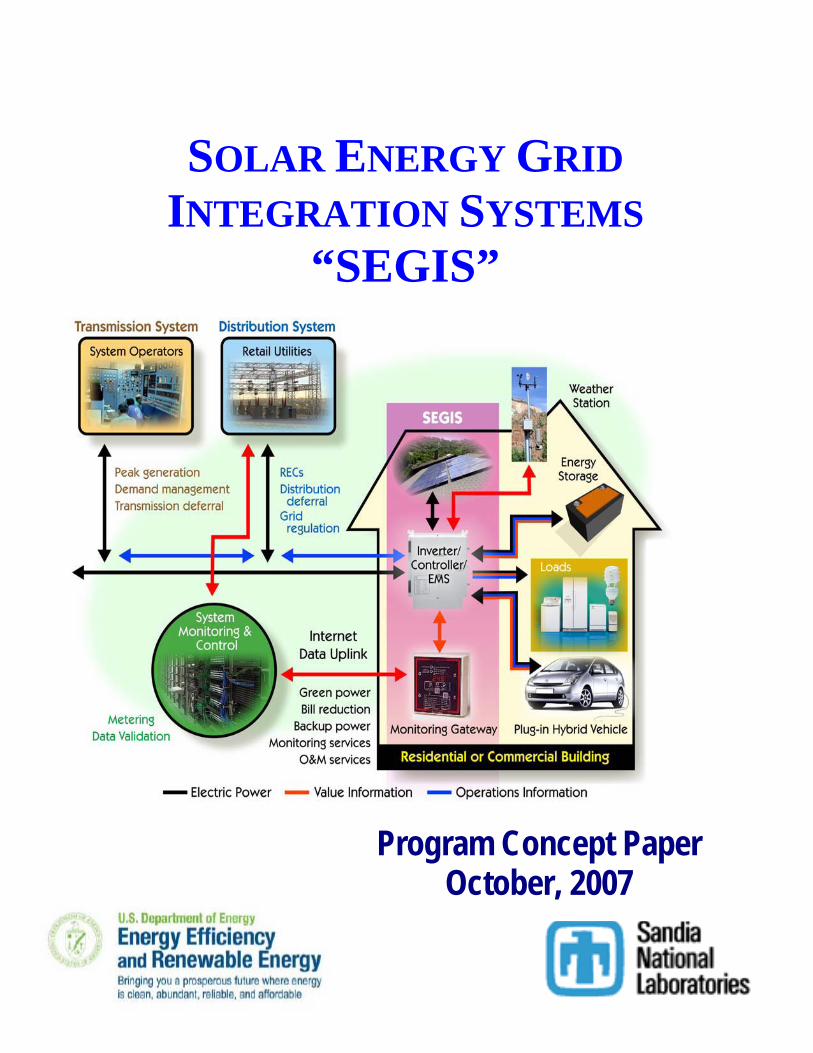
Program Concept Paper October, 2007
SOLAR ENERGY GRID INTEGRATION SYSTEMS
“SEGIS”
TABLE OF CONTENTS
TABLE OF CONTENTS ................................................................................................................ 1 TABLE OF CONTENTS ................................................................................................................ 2 1) Executive Summary ............................................................................................................... 3 2) Vision ..................................................................................................................................... 3 3) Program Objective ................................................................................................................. 3 4) Program Scope ....................................................................................................................... 4 5) High PV Penetration and the Utility Distribution System ..................................................... 5
a) PV System Characteristics and Impacts 5 b) Implications for Utility Operations 6 c) Implications for Solar System Owners 9
6) Approaches to Enable High Penetration .............................................................................. 10 a) Today’s Distribution System 10
i) Mitigating Impact on Current Distribution Infrastructure: ...................................... 10 ii) Improving Value for the Solar Energy System Customer: ...................................... 11
b) Advanced Distribution Systems and Micro-Grids 13 7) Design Concepts for Integrated Inverters, Controllers, BOS and Energy Management ..... 15
a) System Architectures 17 b) Communications 20
i) Anti-islanding Control. ............................................................................................ 20 ii) External Communication. ........................................................................................ 20 iii) Internal Communication. ......................................................................................... 21 iv) Communication Methods and Protocols. ................................................................. 21
c) Inverter/Controller 22 d) Energy Management Systems (EMS) 23 e) Adaptive Logic Controller 24 f) Related Systems 24
i) Energy Storage. .......................................................................................................... 24 ii) Advanced Distribution Systems/Micro-grids. ........................................................... 24 iii) Hybrid Vehicle Systems. .......................................................................................... 25
8) Benefit/Value Analysis ........................................................................................................ 25 a) Reducing Inverter Cost 25 b) Improving System Value 26 c) Value of Storage 26 d) Models for Characterization of Performance and Cost of Energy 27
9) Conclusions .......................................................................................................................... 27 Bibliography ................................................................................................................................. 28 References ..................................................................................................................................... 29
2
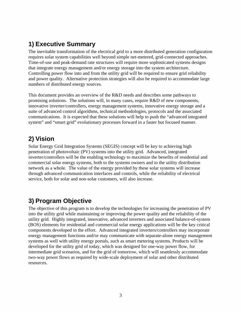
1) Executive Summary The inevitable transformation of the electrical grid to a more distributed generation configuration requires solar system capabilities well beyond simple net-metered, grid-connected approaches. Time-of-use and peak-demand rate structures will require more sophisticated systems designs that integrate energy management and/or energy storage into the system architecture. Controlling power flow into and from the utility grid will be required to ensure grid reliability and power quality. Alternative protection strategies will also be required to accommodate large numbers of distributed energy sources. This document provides an overview of the R&D needs and describes some pathways to promising solutions. The solutions will, in many cases, require R&D of new components, innovative inverter/controllers, energy management systems, innovative energy storage and a suite of advanced control algorithms, technical methodologies, protocols and the associated communications. It is expected that these solutions will help to push the “advanced integrated system” and “smart grid” evolutionary processes forward in a faster but focused manner.
2) Vision Solar Energy Grid Integration Systems (SEGIS) concept will be key to achieving high penetration of photovoltaic (PV) systems into the utility grid. Advanced, integrated inverter/controllers will be the enabling technology to maximize the benefits of residential and commercial solar energy systems, both to the systems owners and to the utility distribution network as a whole. The value of the energy provided by these solar systems will increase through advanced communication interfaces and controls, while the reliability of electrical service, both for solar and non-solar customers, will also increase.
3) Program Objective The objective of this program is to develop the technologies for increasing the penetration of PV into the utility grid while maintaining or improving the power quality and the reliability of the utility grid. Highly integrated, innovative, advanced inverters and associated balance-of-system (BOS) elements for residential and commercial solar energy applications will be the key critical components developed in the effort. Advanced integrated inverters/controllers may incorporate energy management functions and/or may communicate with separate-alone energy management systems as well with utility energy portals, such as smart metering systems. Products will be developed for the utility grid of today, which was designed for one-way power flow, for intermediate grid scenarios, and for the grid of tomorrow, which will seamlessly accommodate two-way power flows as required by wide-scale deployment of solar and other distributed resources.
3
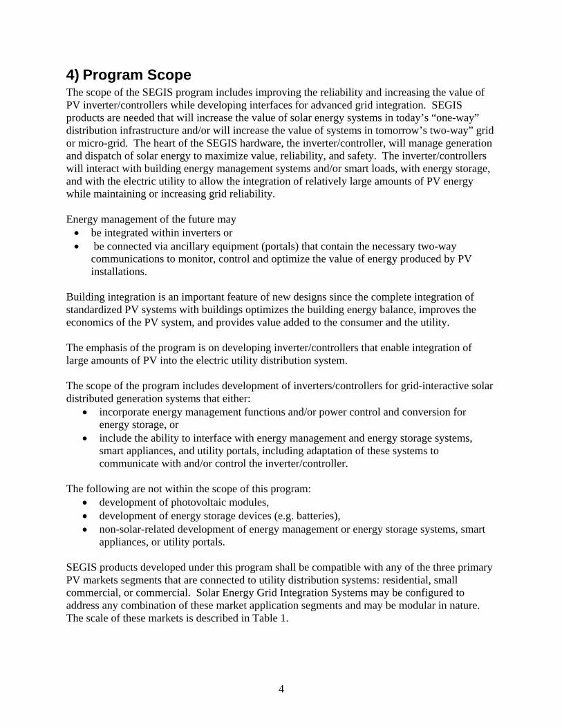
4) Program Scope The scope of the SEGIS program includes improving the reliability and increasing the value of PV inverter/controllers while developing interfaces for advanced grid integration. SEGIS products are needed that will increase the value of solar energy systems in today’s “one-way” distribution infrastructure and/or will increase the value of systems in tomorrow’s two-way” grid or micro-grid. The heart of the SEGIS hardware, the inverter/controller, will manage generation and dispatch of solar energy to maximize value, reliability, and safety. The inverter/controllers will interact with building energy management systems and/or smart loads, with energy storage, and with the electric utility to allow the integration of relatively large amounts of PV energy while maintaining or increasing grid reliability. Energy management of the future may • be integrated within inverters or • be connected via ancillary equipment (portals) that contain the necessary two-way
communications to monitor, control and optimize the value of energy produced by PV installations.
Building integration is an important feature of new designs since the complete integration of standardized PV systems with buildings optimizes the building energy balance, improves the economics of the PV system, and provides value added to the consumer and the utility. The emphasis of the program is on developing inverter/controllers that enable integration of large amounts of PV into the electric utility distribution system. The scope of the program includes development of inverters/controllers for grid-interactive solar distributed generation systems that either:
• incorporate energy management functions and/or power control and conversion for energy storage, or
• include the ability to interface with energy management and energy storage systems, smart appliances, and utility portals, including adaptation of these systems to communicate with and/or control the inverter/controller.
The following are not within the scope of this program:
• development of photovoltaic modules, • development of energy storage devices (e.g. batteries), • non-solar-related development of energy management or energy storage systems, smart
appliances, or utility portals. SEGIS products developed under this program shall be compatible with any of the three primary PV markets segments that are connected to utility distribution systems: residential, small commercial, or commercial. Solar Energy Grid Integration Systems may be configured to address any combination of these market application segments and may be modular in nature. The scale of these markets is described in Table 1.
4
Table 1 Applications Scale Residential Less than 10-kW, single-phase Small Commercial From 10-kW to 50-kW, typically three-phase Commercial Greater than 50-kW, three-phase
5) High PV Penetration and the Utility Distribution System PV systems generate energy with minimal environmental impact. However, a simple PV system without storage provides power only when the sun shines. It does not produce power in the evening when loads can be high, and the power output from a PV system can increase or decrease rapidly due to cloud passages. While the markets for grid-connected residential and commercial PV systems are growing rapidly, the total contribution of PV systems to the nation’s power supply is small and currently has no significant effect on the operation of the nation’s power systems. However, as the quantity of energy generated by solar and other distributed energy systems becomes significant, these systems have the potential to adversely impact utility system operation. To mitigate these impacts, changes are likely to be made to utility/PV system interface requirements and to utility rate structures, which in turn may alter the value of these systems.
a) PV System Characteristics and Impacts Today’s grid-connected residential and commercial systems typically have the following characteristics and associated impacts:
The PV system and the inverter are connected to the grid in parallel with the load. • The load is served whenever the grid is available. • Energy produced by the PV system decreases the apparent load. Energy produced in
excess of the load flows into the distribution system. • The PV system has no storage and cannot serve the load in the absence of the grid. • The PV system produces power at unity power factor and utility supplies all Volt
Ampere reactive power.
The inverter meets the requirements of IEEE 1547-2005. • There is no direct communication or control between the utility and the inverter. • If the inverter senses that utility service has fallen outside set boundaries for voltage
and/or frequency or utility service is interrupted, the inverter will disconnect from the utility until normal conditions resume. The load remains connected to the utility.
For residential and small-commercial systems, the grid interconnection is typically net-
metered at a flat rate. • The price of energy is constant throughout the day and there is no demand charge. • When excess energy is produced, the meter spins backwards.
• Energy is bought and sold at the same price. • Over the course of a month or a year, if energy produced exceeds energy used, the
utility will not pay for the excess above the amount used.
5
• If the grid is not available, grid-tied PV inverters (without energy storage and load transfer capability) cannot serve the load, even when sunlight is present and the PV modules are able to produce power.
For large-scale commercial systems, rate structures are more complex. • Time-of-use rates often apply, with cost of energy being higher during periods of
peak demand. • Demand charges may apply with a significant portion of the utility bill derived from
the highest power requirement (kW) measured over a 15 to 30 minute interval during the monthly billing period.
• A charge for VARS (reactive power) may apply. • Net metering is less common, and some systems are not permitted to deliver any
power back to the utility. In this case, the load must always exceed the energy generated by the solar system.
• Other systems have dual meters and power is purchased by the utility at a lower rate than the rate charged for power supplied by the utility to the customer.
b) Implications for Utility Operations There are utility concerns that high penetration of inverter-based solar energy systems along with other distributed generation sources on distribution lines will contribute to instabilities and possibly unsafe operations due to one or several of the following design and operational characteristics:
Because PV energy production does not always coincide with the times when it is most economical for utilities to use it, it can negatively impact utility operating economics. • No power is available in the hours immediately after sunset when demand for power
may be high. Thus, the utility must increase peak power generation during these hours.
• Conversely, utility demand is low in the early morning hours (sunrise to ~ 9 am). Power from solar systems during these hours results in a lower load for the utility, decreasing the need for economical 24-hr base load power, and increasing the need for more expensive intermediate and peaking power during the rest of the day.
From the utility perspective, net-metered, flat rate customers, especially those whose net
demand approaches zero, do not pay a fair share of their costs. • If energy generated equals energy used, then energy-related charges (the dominant
part of most residential and small commercial bills) will approach zero. • Without a demand (kW) charge or significant interconnection charge, customers will
pay little for the benefits of being connected to the grid.
Power production from an individual PV system may increase or decrease rapidly due to cloud passages. • In most cases, the rate of change of the collective output from PV systems will be
moderated by the geographic dispersal of the systems. However, in a case where the service area is relatively small and rapid weather changes can occur, measurements
6
conducted by Tucson Electric Power show that a rapidly-passing cloud bank can essentially eliminate all solar generation across Tucson in less than 5 minutes.1
• The introduction of significant amounts of rapidly-changing intermittent power in a utility system can affect the controls on and increase the need for spinning reserve.
If a utility experiences sagging voltage under high demand conditions, IEEE 1547
requires that inverters disconnect. However, since the loads are not automatically disconnected, the utility will see an increase in demand, potentially aggravating the cause of the voltage sag and leading to a blackout (decreased utility system reliability).
The addition of large numbers of inverters has been shown to increase the probability of
islanding, during which inverters continue to supply local loads after a utility fault.2 Other impacts to the utility include: • Inverters are limited in their ability to introduce extremely high levels of short circuit
current, but the addition of large systems or many small systems can sum to significant short circuit currents and possibly cause equipment malfunction or damage.
• Utility protection relays are designed to detect a fault, e.g. an arc to ground created by a tree branch falling across a line. The relays briefly disconnect from the fault to allow the fault to clear, and then reconnect to provide continuing service. If islanding detection fails and inverters remain on-line: • The inverters may be damaged by the reconnect. • The inverters may continue to supply current which could maintain the fault,
causing the utility protection relays to lock open. Utility technicians must then be dispatched to reset the relays, and customers may be left without power for a significant time.
• When technicians are dispatched, if the inverters are still on-line, the safety of the technicians is threatened because of power being supplied to the load side of disconnects and downed power lines.
Large power flow into distribution systems that were designed for one-way flow may
impact system regulation and protection. Fully understanding the effects of high penetration on distribution system operation and design requires further study, but a number of potential issues have been identified. • Reverse power flow can interfere with voltage regulation. Voltage regulators
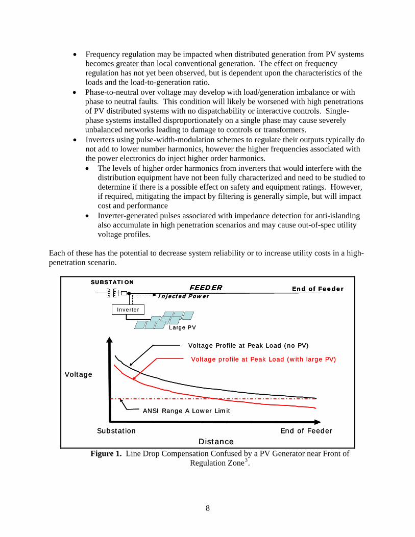
measure current and voltage and will maintain higher voltage at the beginning of a radial line to ensure adequate voltage at the end of the line, in proportion to power flow. Introduction of significant distributed power downstream from the voltage regulation system will make line loading appear to be low. • If the power is injected just downstream from voltage regulation, customers at the
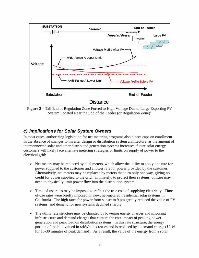
end of the line will experience low voltage, as shown in Figure 1. • If the power is injected near the end of the line, high voltage may occur at that
point, as shown in Figure 2. • Fuses are designed to protect the current carrying capability of a line, but injection of
power downstream from a fuse will not be detected, leading to the potential for overload.
7
• Frequency regulation may be impacted when distributed generation from PV systems becomes greater than local conventional generation. The effect on frequency regulation has not yet been observed, but is dependent upon the characteristics of the loads and the load-to-generation ratio.
• Phase-to-neutral over voltage may develop with load/generation imbalance or with phase to neutral faults. This condition will likely be worsened with high penetrations of PV distributed systems with no dispatchability or interactive controls. Single-phase systems installed disproportionately on a single phase may cause severely unbalanced networks leading to damage to controls or transformers.
• Inverters using pulse-width-modulation schemes to regulate their outputs typically do not add to lower number harmonics, however the higher frequencies associated with the power electronics do inject higher order harmonics. • The levels of higher order harmonics from inverters that would interfere with the
distribution equipment have not been fully characterized and need to be studied to determine if there is a possible effect on safety and equipment ratings. However, if required, mitigating the impact by filtering is generally simple, but will impact cost and performance
• Inverter-generated pulses associated with impedance detection for anti-islanding also accumulate in high penetration scenarios and may cause out-of-spec utility voltage profiles.
Each of these has the potential to decrease system reliability or to increase utility costs in a high-penetration scenario.
Voltage Profile at Peak Load (no PV)
Substation End of Feeder
Voltage pro file at Peak Load (w ith large PV)
ANSI Range A Lower Lim it
D istance
Voltage
SUBSTATIO NFEED ER End of Feeder
Injected Pow er
Inverter
Large PV
Voltage Profile at Peak Load (no PV)
Substation End of Feeder
Voltage pro file at Peak Load (w ith large PV)
ANSI Range A Lower Lim it
D istance
Voltage
SUBSTATIO NFEED ER End of Feeder
SUBSTATIO NFEED ER End of Feeder
Injected Pow er
Inverter
Large PV
Figure 1. Line Drop Compensation Confused by a PV Generator near Front of
Regulation Zone3.
8
SUBSTATIONFEEDER End of Feeder
Substation End of Feeder
ANSI Range A Lower Limit
Distance
Voltage
ANSI Range A Upper Limit
Voltage Profile After PV
Voltage Profile Before PV
Injected PowerInverter
Large PV
SUBSTATIONFEEDER End of Feeder
Injected Power
Substation End of Feeder
ANSI Range A Lower Limit
Distance
Voltage
ANSI Range A Upper Limit
Voltage Profile After PV
InverterLarge PV
InverterLarge PV
Voltage Profile Before PV
Figure 2 – Tail End of Regulation Zone Forced to High Voltage Due to Large Exporting PV
System Located Near the End of the Feeder (or Regulation Zone)3
c) Implications for Solar System Owners In most cases, authorizing legislation for net metering programs also places caps on enrollment. In the absence of changes to inverter design or distribution system architecture, as the amount of interconnected solar and other distributed generation systems increases, future solar energy customers will likely face alternate metering strategies or limits on supply of power to the electrical grid:
Net meters may be replaced by dual meters, which allow the utility to apply one rate for power supplied to the customer and a lower rate for power provided by the customer. Alternatively, net meters may be replaced by meters that turn only one way, giving no credit for power supplied to the grid. Ultimately, to protect their systems, utilities may need to physically limit power flow into the distribution system.
Time-of-use rates may be imposed to reflect the true cost of supplying electricity. Time-of-use rates were briefly imposed on new, net-metered, residential solar systems in California. The high rates for power from sunset to 9 pm greatly reduced the value of PV systems, and demand for new systems declined sharply.
The utility rate structure may be changed by lowering energy charges and imposing infrastructure and demand charges that capture the cost impact of peaking power generation and peak load on distribution systems. In this rate structure, the energy portion of the bill, valued in ¢/kWh, decreases and is replaced by a demand charge ($/kW for 15-30 minutes of peak demand). As a result, the value of the energy from a solar
9

system is reduced, and a cloud at the wrong time or demand after sunset can lead to a high demand charges.
Businesses and industrial sites with large motors are provided Volt-Ampere reactive power (VARs) by the utility. Charges for this capability will likely be imposed on users unless PV or renewable energy generation can supply the VArs at the source.
Each of these has the potential to decrease the value to the owner of the energy from the solar energy system. While decreasing system cost is one approach to providing competitive energy, managing energy flows to improve system value is likely the needed approach for the future grid. Designing systems to manage energy flows by incorporating features such as energy management and/or energy storage will allow customers to improve system value by selling energy to the utility when the value is high, buying energy when the cost is low. Such systems also make it possible for the customer to operate independently of the grid, for example during storm-related grid outages. These value-added concepts are discussed further in the following sections.
While decreasing system cost is one approach to pro-viding competitive energy, managing energy flows to improve system value is likely the needed approach for the future grid.
6) Approaches to Enable High Penetration
a) Today’s Distribution System Utility distribution systems typically are designed for a 30-year life, but in reality they last much longer than that. As a result, in the near term and for most locations, the design of PV systems in a high-penetration scenario must be compatible with reliable operation of a grid infrastructure that will be little changed from current practice. The alternative, saddling individual PV installations with the cost of upgrading the distribution infrastructure, may not be economical. At the same time, it is realistic to expect that most new systems will not be net-metered under flat rate structures, but may be subject to time-of-use, demand, and other charges while potentially receiving less for excess generated energy. In this section, approaches to enabling high penetration of PV into the current distribution infrastructure while maintaining or improving PV system value and utility system reliability are discussed. i) Mitigating Impact on Current Distribution Infrastructure: As described above, high penetration of PV systems has the potential to interfere with grid reliability and control. Even as utilities contemplate replacement of the existing infrastructure with new hardware and controls specifically designed to accommodate two-way power flows, steps can be taken to mitigate the impact of high penetration of distributed energy sources on the distribution infrastructure. These steps assume that the most expensive parts of the distribution system remain unchanged, but they do require additional communication capabilities. A key step is to enable the distribution system to interactively control connection of the inverter/controller to the grid. One possible approach is to replace the current anti-islanding approach with interactive dispatch so the utility can command an inverter to ride through voltage sag, rather than having a large number of inverters go off-line while leaving the loads on-line.
10
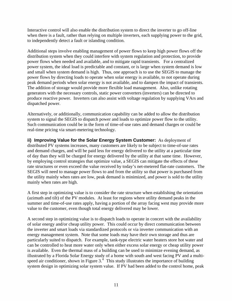
Interactive control will also enable the distribution system to direct the inverter to go off-line when there is a fault, rather than relying on multiple inverters, each supplying power to the grid, to independently detect a fault or islanding condition. Additional steps involve enabling management of power flows to keep high power flows off the distribution system when they could interfere with system regulation and protection, to provide power flows when needed and available, and to mitigate rapid transients. For a centralized power system, the ideal load is predictable and constant, or is large when system demand is low and small when system demand is high. Thus, one approach is to use the SEGIS to manage the power flows by directing loads to operate when solar energy is available, to not operate during peak demand periods when solar energy is not available, and to dampen the impact of transients. The addition of storage would provide more flexible load management. Also, unlike rotating generators with the necessary controls, static power converters (inverters) can be directed to produce reactive power. Inverters can also assist with voltage regulation by supplying VArs and dispatched power. Alternatively, or additionally, communication capability can be added to allow the distribution system to signal the SEGIS to dispatch power and loads to optimize power flow to the utility. Such communication could be in the form of time-of-use rates and demand charges or could be real-time pricing via smart-metering technology. ii) Improving Value for the Solar Energy System Customer: As deployment of distributed PV systems increases, many customers are likely to be subject to time-of-use rates and demand charges, and will be paid less for energy delivered to the utility at a particular time of day than they will be charged for energy delivered by the utility at that same time. However, by employing control strategies that optimize value, a SEGIS can mitigate the effects of these rate structures or even exceed the value received by today’s net-metered flat-rate customers. The SEGIS will need to manage power flows to and from the utility so that power is purchased from the utility mainly when rates are low, peak demand is minimized, and power is sold to the utility mainly when rates are high. A first step in optimizing value is to consider the rate structure when establishing the orientation (azimuth and tilt) of the PV modules. At least for regions where utility demand peaks in the summer and time-of-use rates apply, having a portion of the array facing west may provide more value to the customer, even though total energy delivered may be lower. A second step in optimizing value is to dispatch loads to operate in concert with the availability of solar energy and/or cheap utility power. This could occur by direct communication between the inverter and smart loads via standardized protocols or via inverter communication with an energy management system. Note that some loads may have their own storage and thus are particularly suited to dispatch. For example, tank-type electric water heaters store hot water and can be controlled to heat more water only when either excess solar energy or cheap utility power is available. Even the thermal mass of a building can be used to minimize evening demand, as illustrated by a Florida Solar Energy study of a home with south and west facing PV and a multi-speed air conditioner, shown in Figure 3.4 This study illustrates the importance of building system design in optimizing solar system value. If PV had been added to the control home, peak
11
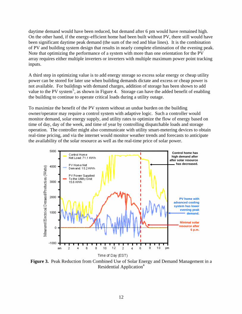
daytime demand would have been reduced, but demand after 6 pm would have remained high. On the other hand, if the energy-efficient home had been built without PV, there still would have been significant daytime peak demand (the sum of the red and blue lines). It is the combination of PV and building system design that results in nearly complete elimination of the evening peak. Note that optimizing the performance of a system with more than one orientation for the PV array requires either multiple inverters or inverters with multiple maximum power point tracking inputs. A third step in optimizing value is to add energy storage so excess solar energy or cheap utility power can be stored for later use when building demands dictate and excess or cheap power is not available. For buildings with demand charges, addition of storage has been shown to add value to the PV system5, as shown in Figure 4. Storage can have the added benefit of enabling the building to continue to operate critical loads during a utility outage. To maximize the benefit of the PV system without an undue burden on the building owner/operator may require a control system with adaptive logic. Such a controller would monitor demand, solar energy supply, and utility rates to optimize the flow of energy based on time of day, day of the week, and time of year by controlling dispatchable loads and storage operation. The controller might also communicate with utility smart-metering devices to obtain real-time pricing, and via the internet would monitor weather trends and forecasts to anticipate the availability of the solar resource as well as the real-time price of solar power.
Control home has high demand after
after solar resource has decreased.
PV home with advanced cooling system has lower
evening peak demand.
Minimal solar resource after
6 p.m.
Figure 3. Peak Reduction from Combined Use of Solar Energy and Demand Management in a
Residential Application4
12
Figure 4. Cumulative Cash Flow for Commercial Customers – Comparing PV-alone, PV +
Local Load Management (MBES) Storage and PV + Emergency Storage Options.5
b) Advanced Distribution Systems and Micro-Grids As penetration of distributed energy systems increases and the necessary technology is developed, it is anticipated that the distribution system will evolve to accommodate two-way power flows and will take full advantage of distributed energy resources. This evolution will take place first in new residential, business, and industrial developments, but for much of the grid, may not occur until existing distribution systems must be replaced due to age. The technology to dispatch residential and commercial loads, such as air conditioning and electric water heating, already exists and is being used during periods of peak demand. Customers for which a secure source of electric power is essential use standby generation and/or uninterruptible power supplies to operate independently of the electrical grid during outages, and some use advanced technology to transfer seamlessly from grid power to independent sources. However, with the exception of residential PV systems, flow of power from distributed energy sources into the distribution grid is relatively uncommon. If the recent growth rate in installation of PV systems continues, penetration levels of 5 to 10% could occur in less than a decade6, with higher levels occurring locally. Deployment of other distributed resources may also increase. Those resources include, but are not limited to: intermittent resources such as wind and solar; fuel-based energy sources in combined heat and power systems, such as fuel cells, microturbines, and engine-generators; and dispatch of engine-generators that today provide only emergency power in the event of a utility outage. Power flow from these systems may provide a significant portion of the energy used by other customers. Utilities will use these systems to minimize the cost and environmental impact of power generation, to manage peak demands, to provide ancillary services such as spinning reserve, to improve system reliability, and to improve power quality. At a site level, the ability of power
13
electronics to improve power quality and provide seamless transfer from utility to site power sources has already been demonstrated7. Utilities may place utility-owned distributed generation and/or storage within the distribution system to improve operations and reliability. Micro-grids, placed at critical weak points of the utility grid, can provide a stabilizing role to the grid while ensuring the loads connected to the micro-grids during utility outages continue to function just as if the utility were still there. To accommodate and optimize management of these resources, it is expected that the advanced distribution system will be a “Smart Grid”. One general definition for the smart grid is:
A modern distributed and intelligent generation and distribution network using digital technology for controls and advanced electronics for switching and protection.
Features of the smart distribution system may include but are not limited to:
1. Automation for power flow and energy management 2. Management of the interface between the utility, distributed resources, and micro-grids 3. Management of all power flow transitions 4. Real time pricing and analysis for the connected community 5. Management of the intermittency of renewable solar resources
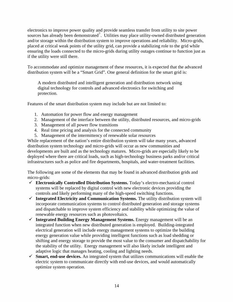
While replacement of the nation’s entire distribution system will take many years, advanced distribution system technology and micro-grids will occur as new communities and developments are built and as the technology matures. Micro-grids are especially likely to be deployed where there are critical loads, such as high-technology business parks and/or critical infrastructures such as police and fire departments, hospitals, and water-treatment facilities. The following are some of the elements that may be found in advanced distribution grids and micro-grids:
Electronically Controlled Distribution Systems. Today’s electro-mechanical control systems will be replaced by digital control with new electronic devices providing the controls and likely performing many of the high-speed switching functions.
Integrated Electricity and Communication Systems. The utility distribution system will incorporate communication systems to control distributed generation and storage systems and dispatchable to improve system efficiency and stability while optimizing the value of renewable energy resources such as photovoltaics.
Integrated Building Energy Management Systems. Energy management will be an integrated function when new distributed generation is employed. Building-integrated electrical generation will include energy management systems to optimize the building energy generation value while providing intelligent functions such as load shedding or shifting and energy storage to provide the most value to the consumer and dispatchability for the stability of the utility. Energy management will also likely include intelligent and adaptive logic that manages heating, cooling and lighting needs.
Smart, end-use devices. An integrated system that utilizes communications will enable the electric system to communicate directly with end-use devices, and would automatically optimize system operation.
14
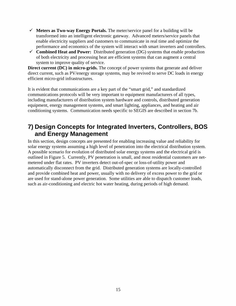
Meters as Two-way Energy Portals. The meter/service panel for a building will be transformed into an intelligent electronic gateway. Advanced meters/service panels that enable electricity suppliers and customers to communicate in real time and optimize the performance and economics of the system will interact with smart inverters and controllers.
Combined Heat and Power: Distributed generation (DG) systems that enable production of both electricity and processing heat are efficient systems that can augment a central system to improve quality of service.
Direct current (DC) in micro-grids. The concept of power systems that generate and deliver direct current, such as PV/energy storage systems, may be revived to serve DC loads in energy efficient micro-grid infrastructures. It is evident that communications are a key part of the “smart grid,” and standardized communications protocols will be very important to equipment manufacturers of all types, including manufacturers of distribution system hardware and controls, distributed generation equipment, energy management systems, and smart lighting, appliances, and heating and air conditioning systems. Communication needs specific to SEGIS are described in section 7b.
7) Design Concepts for Integrated Inverters, Controllers, BOS and Energy Management
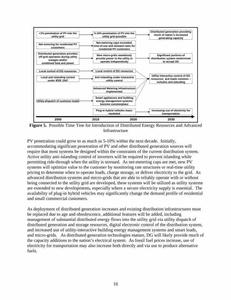
In this section, design concepts are presented for enabling increasing value and reliability for solar energy systems assuming a high level of penetration into the electrical distribution system. A possible scenario for evolution of distributed solar energy systems and the electrical grid is outlined in Figure 5. Currently, PV penetration is small, and most residential customers are net-metered under flat rates. PV inverters detect out-of-spec or loss-of-utility power and automatically disconnect from the grid. Distributed generation systems are locally-controlled and provide combined heat and power, usually with no delivery of excess power to the grid or are used for stand-alone power generation. Some utilities are able to dispatch customer loads, such as air-conditioning and electric hot water heating, during periods of high demand.
15
2000 2010 2020 2030
Local anti-islanding controlunder IEEE 1547
Anti-islanding under interactive utility control
Net-metering for residential PV customers
Net-metering caps exceeded, time-of-use and demand rates for
residential PV customers
Local control of DG resources Local control of DG resources
Distributed generation provides off-grid operation during utility
outages and/orcombined heat and power
New micro-grids seamlessly provide power to the utility or
operate independently
Utility-dispatch of customer loadsSmart appliances and building energy management systems
become commonplace
Advanced Metering Infrastructure Implemented
Plug-in hybrid vehicles mass-marketed
<1% penetration of PV into the utility grid
5-10% penetration of PV into the utility grid possible
Significant portions of distribution system modernized
to accept DG
Utility interactive control of DG resources and loads common –
includes anti-islanding
Distributed generation providing much of nation’s increased
generating capacity
Increasing use of electricity for transportation
Figure 5. Possible Time Tine for Introduction of Distributed Energy Resources and Advanced
Infrastructure
PV penetration could grow to as much as 5-10% within the next decade. Initially, accommodating significant penetration of PV and other distributed generation sources will require that most systems be designed within the constraints of the current distribution system. Active utility anti-islanding control of inverters will be required to prevent islanding while permitting ride-through when the utility is stressed. As net-metering caps are met, new PV systems will optimize value to the customer by monitoring rate structures or real-time utility pricing to determine when to operate loads, charge storage, or deliver electricity to the grid. As advanced distribution systems and micro-grids that are able to reliably operate with or without being connected to the utility grid are developed, these systems will be utilized as utility systems are extended to new developments, especially where a secure electricity supply is essential. The availability of plug-in hybrid vehicles may significantly change the demand profile of residential and small commercial customers. As deployment of distributed generation increases and existing distribution infrastructures must be replaced due to age and obsolescence, additional features will be added, including management of substantial distributed energy flows into the utility grid via utility dispatch of distributed generation and storage resources, digital electronic control of the distribution system, and increased use of utility-interactive building energy management systems and smart loads, and micro-grids. As distributed generation technologies mature, DG will likely provide much of the capacity additions to the nation’s electrical system. As fossil fuel prices increase, use of electricity for transportation may also increase both directly and via use to produce alternative fuels.
16
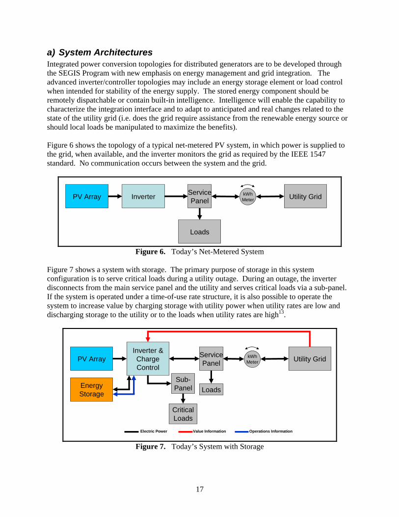
a) System Architectures Integrated power conversion topologies for distributed generators are to be developed through the SEGIS Program with new emphasis on energy management and grid integration. The advanced inverter/controller topologies may include an energy storage element or load control when intended for stability of the energy supply. The stored energy component should be remotely dispatchable or contain built-in intelligence. Intelligence will enable the capability to characterize the integration interface and to adapt to anticipated and real changes related to the state of the utility grid (i.e. does the grid require assistance from the renewable energy source or should local loads be manipulated to maximize the benefits). Figure 6 shows the topology of a typical net-metered PV system, in which power is supplied to the grid, when available, and the inverter monitors the grid as required by the IEEE 1547 standard. No communication occurs between the system and the grid.
PV Array Inverter
Loads
kWhMeter Utility GridService
Panel
Figure 6. Today’s Net-Metered System
Figure 7 shows a system with storage. The primary purpose of storage in this system configuration is to serve critical loads during a utility outage. During an outage, the inverter disconnects from the main service panel and the utility and serves critical loads via a sub-panel. If the system is operated under a time-of-use rate structure, it is also possible to operate the system to increase value by charging storage with utility power when utility rates are low and discharging storage to the utility or to the loads when utility rates are high13.
PV ArrayInverter &ChargeControl
Loads
kWhMeter Utility GridService
Panel
EnergyStorage
Sub-Panel
Critical Loads
Electric Power Value Information Operations Information
Figure 7. Today’s System with Storage
17
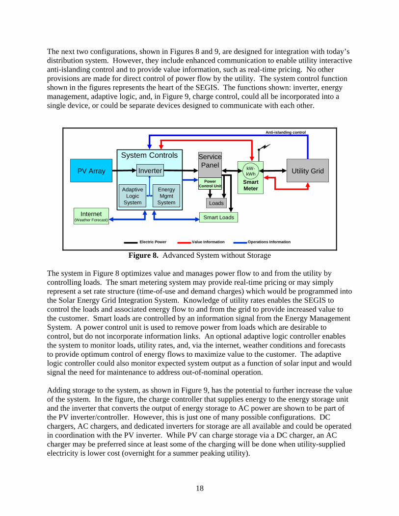
The next two configurations, shown in Figures 8 and 9, are designed for integration with today’s distribution system. However, they include enhanced communication to enable utility interactive anti-islanding control and to provide value information, such as real-time pricing. No other provisions are made for direct control of power flow by the utility. The system control function shown in the figures represents the heart of the SEGIS. The functions shown: inverter, energy management, adaptive logic, and, in Figure 9, charge control, could all be incorporated into a single device, or could be separate devices designed to communicate with each other.
ServicePanel
MotorizedBreakers
PowerControl Unit
System Controls
SmartMeter
PV Array kW-kWh Utility Grid
Anti-islanding control
Adaptive Logic
System
EnergyMgmt
System Loads
Smart Loads
Electric Power Value Information Operations Information
Inverter
Internet(Weather Forecast)
Figure 8. Advanced System without Storage
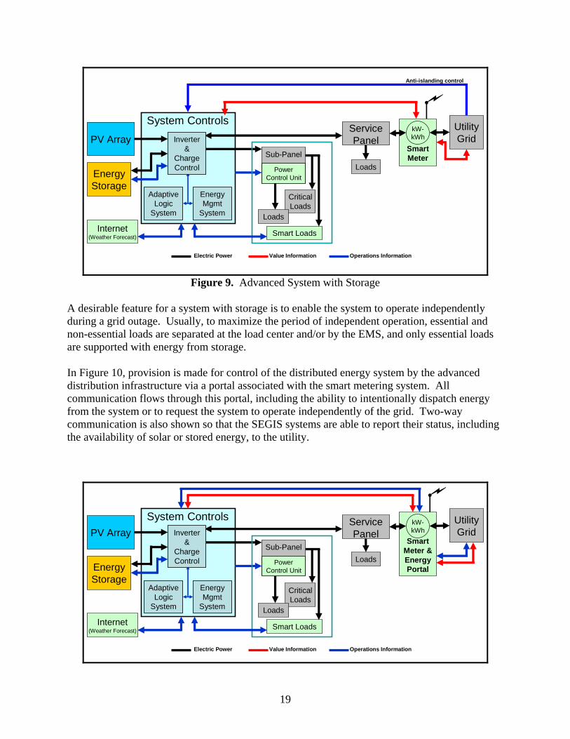
The system in Figure 8 optimizes value and manages power flow to and from the utility by controlling loads. The smart metering system may provide real-time pricing or may simply represent a set rate structure (time-of-use and demand charges) which would be programmed into the Solar Energy Grid Integration System. Knowledge of utility rates enables the SEGIS to control the loads and associated energy flow to and from the grid to provide increased value to the customer. Smart loads are controlled by an information signal from the Energy Management System. A power control unit is used to remove power from loads which are desirable to control, but do not incorporate information links. An optional adaptive logic controller enables the system to monitor loads, utility rates, and, via the internet, weather conditions and forecasts to provide optimum control of energy flows to maximize value to the customer. The adaptive logic controller could also monitor expected system output as a function of solar input and would signal the need for maintenance to address out-of-nominal operation. Adding storage to the system, as shown in Figure 9, has the potential to further increase the value of the system. In the figure, the charge controller that supplies energy to the energy storage unit and the inverter that converts the output of energy storage to AC power are shown to be part of the PV inverter/controller. However, this is just one of many possible configurations. DC chargers, AC chargers, and dedicated inverters for storage are all available and could be operated in coordination with the PV inverter. While PV can charge storage via a DC charger, an AC charger may be preferred since at least some of the charging will be done when utility-supplied electricity is lower cost (overnight for a summer peaking utility).
18
SmartMeter
System ControlsPV Array
kW-kWh
UtilityGrid
Internet(Weather Forecast)
Anti-islanding control
ServicePanel
Adaptive Logic
System
EnergyMgmt
System
Smart Loads
EnergyStorage
CriticalLoads
Sub-Panel
MotorizedBreakers
Loads
Inverter&
ChargeControl
Electric Power Value Information Operations Information
PowerControl Unit
Loads
Figure 9. Advanced System with Storage
A desirable feature for a system with storage is to enable the system to operate independently during a grid outage. Usually, to maximize the period of independent operation, essential and non-essential loads are separated at the load center and/or by the EMS, and only essential loads are supported with energy from storage.
In Figure 10, provision is made for control of the distributed energy system by the advanced distribution infrastructure via a portal associated with the smart metering system. All communication flows through this portal, including the ability to intentionally dispatch energy from the system or to request the system to operate independently of the grid. Two-way communication is also shown so that the SEGIS systems are able to report their status, including the availability of solar or stored energy, to the utility.
Smart Loads
System Controls
SmartMeter &EnergyPortal
PV ArraykW-kWh
UtilityGrid
ServicePanel
Adaptive Logic
System
EnergyMgmt
System
LoadsEnergyStorage
CriticalLoads
Loads
Inverter&
ChargeControl
Electric Power Value Information Operations Information
Internet(Weather Forecast)
Sub-Panel
MotorizedBreakers
PowerControl Unit
19
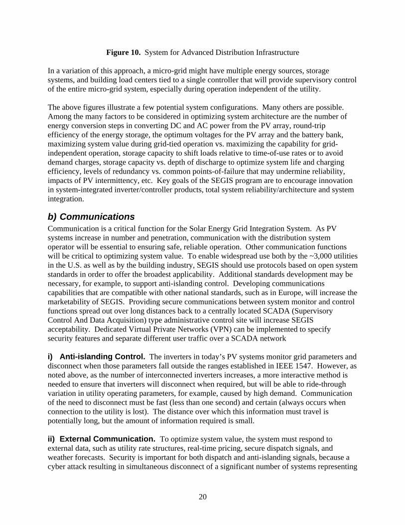
Figure 10. System for Advanced Distribution Infrastructure In a variation of this approach, a micro-grid might have multiple energy sources, storage systems, and building load centers tied to a single controller that will provide supervisory control of the entire micro-grid system, especially during operation independent of the utility. The above figures illustrate a few potential system configurations. Many others are possible. Among the many factors to be considered in optimizing system architecture are the number of energy conversion steps in converting DC and AC power from the PV array, round-trip efficiency of the energy storage, the optimum voltages for the PV array and the battery bank, maximizing system value during grid-tied operation vs. maximizing the capability for grid-independent operation, storage capacity to shift loads relative to time-of-use rates or to avoid demand charges, storage capacity vs. depth of discharge to optimize system life and charging efficiency, levels of redundancy vs. common points-of-failure that may undermine reliability, impacts of PV intermittency, etc. Key goals of the SEGIS program are to encourage innovation in system-integrated inverter/controller products, total system reliability/architecture and system integration.
b) Communications Communication is a critical function for the Solar Energy Grid Integration System. As PV systems increase in number and penetration, communication with the distribution system operator will be essential to ensuring safe, reliable operation. Other communication functions will be critical to optimizing system value. To enable widespread use both by the ~3,000 utilities in the U.S. as well as by the building industry, SEGIS should use protocols based on open system standards in order to offer the broadest applicability. Additional standards development may be necessary, for example, to support anti-islanding control. Developing communications capabilities that are compatible with other national standards, such as in Europe, will increase the marketability of SEGIS. Providing secure communications between system monitor and control functions spread out over long distances back to a centrally located SCADA (Supervisory Control And Data Acquisition) type administrative control site will increase SEGIS acceptability. Dedicated Virtual Private Networks (VPN) can be implemented to specify security features and separate different user traffic over a SCADA network i) Anti-islanding Control. The inverters in today’s PV systems monitor grid parameters and disconnect when those parameters fall outside the ranges established in IEEE 1547. However, as noted above, as the number of interconnected inverters increases, a more interactive method is needed to ensure that inverters will disconnect when required, but will be able to ride-through variation in utility operating parameters, for example, caused by high demand. Communication of the need to disconnect must be fast (less than one second) and certain (always occurs when connection to the utility is lost). The distance over which this information must travel is potentially long, but the amount of information required is small. ii) External Communication. To optimize system value, the system must respond to external data, such as utility rate structures, real-time pricing, secure dispatch signals, and weather forecasts. Security is important for both dispatch and anti-islanding signals, because a cyber attack resulting in simultaneous disconnect of a significant number of systems representing
20
significant penetration of a portion of the grid could overwhelm the ability of the utility reserve capacity, causing an outage8. Relative to islanding control, the speed with which data must be transferred is lower, depending on the need, as follows9:
• Spinning reserve (replacement of lost capacity), signal sent ~1/second. Thermal generation units providing spinning reserve achieve full output in a few minutes. Hydroelectric units respond faster.
• Frequency and Area Regulation (to maintain frequency control), signals sent very few seconds. Response time is over several minutes.
• Voltage regulation. The line voltage provides the signal. Very fast response (sub-cycle), e.g. using droop algorithms is possible. Central dispatch is slower (few cycles).
• Peak Shaving (Demand Response). The signal can be built into peak demand rate structures or real-time pricing, which may be updated at intervals of 1 to 60 minutes, depending on the utility. Some utilities also dispatch loads to shave peak demand.
• Backfeed Control. Some systems, especially large commercial systems, may be restricted from exporting power to the utility. Often, these systems are sized so that the system output never exceeds load, but in the event it does or if the system is larger and uses storage to absorb excess power, then the response must be faster than the reverse-power relay, which is typically sub-cycle.
iii) Internal Communication. Communication within the system is critical to controlling loads and storage to optimize system value while maintaining system safety. Distance over which data must travel will generally be modest, unless the site is a large commercial system or micro-grid. In addition to ensuring safe, efficient system operation, a system that is connected under time-of-day and/or demand rate structures will be trying to balance the available energy from the solar system, other connected distributed generation sources, and storage with variations in loads and utility pricing. While solar output can change rapidly with cloud passages and loads can change with the flick of a switch, utility demand charges are usually assessed over a period of 15-30 minutes, so the system has time to respond. However, in the event of off-grid operation, the system must act quickly to prevent load from exceeding maximum system capability (maximum inverter rating and/or available solar plus storage system discharge capability) at any given time. If the system is not permitted to export power, then loads, storage, or the inverter output must be controlled to avoid backfeed (less than one cycle). iv) Communication Methods and Protocols. Newmiller et al. (2007) have provided a summary of the characteristics of a variety of communications methods and protocol. Those and others are summarized here:
• Dedicated copper wiring. Large transmission-connected generators use dedicated copper wiring for control, but the cost to connect with large numbers of individual distributed generation systems would be very high.
• Ad-hoc mesh networks. Smart, granular network topologies that utilize ad-hoc connection methods, whereby individual devices discover others within range to form a cooperative mesh communication network capable of establishing a massive infrastructure with end-to-end routing links
• Continuous-carrier power line communications carriers (PLCC). Used by some utilities for automated meter reading systems. The PLCC signal is lost if the connection
21
to the utility is lost, so this signal could be effective for inverter anti-islanding control. Drawbacks are high cost, low bandwidth, and high power demand.
• Broadband-over-Power-Line. This approach takes advantage of existing power line infrastructure to communicate data, but this technology has faced technical issues, including interference with other radio spectrum users and interference from loads. Some systems have gone to digital multi-carrier modulation scheme to mitigate radio interference issues.
• Ethernet. Provides communications within buildings, but must be connected to a wide-area-network technology, such as cable television. Wide-area networks do not have sufficient reliability to support protection functions.
• Wireless Local Area Network (IEEE 802.11). Used inside and outside of buildings to provide short distance wireless data.
• Wireless Interoperability for Microwave Access (WiMAX) (IEEE 802.16) Provides longer range wireless access.
• Wireless Metropolitan Area Networks (WirelessMAN or WiMAX, IEEE 802.16d). A standards-based technology enabling the delivery of last mile wireless broadband access as an alternative to cable and DSL. Used in urban environments to transmit 2km without line-of-sight antenna configurations and up to 10km with unobstructed path.
• Personal Area Networks, e.g. IEEE 802.15.4, provide short distance (few meters) wireless communications.
• Energy Management Systems, BACnet is a standard in America, Europe, and over 30 countries developed by the American Society of Heating, Refrigerating and Air-Conditioning Engineers (ASHRAE-135) for building automation and control networks. ANSI/CEA-709.1-B establishes another standard for control networking. It provides one of the data link/physical layers of BACnet.
• Other. A variety of other technologies are available, including conventional telephone land-lines, cellular telephone, spread-spectrum wireless radios and pagers. Some utilities have used wireless technology to dispatch customer loads, e.g. Nevada Power’s Cool Share program.
c) Inverter/Controller Development of the inverter/controller is a central element of the SEGIS program. The inverter transforms dc power from the PV array to grid-quality ac power. Depending upon the system architecture, the inverter may also charge and discharge energy storage, and may control smart loads, e.g. smart appliances, especially in residential systems. The inverter/controller, if it contains adaptive logic, may also determine when excess energy is dispatched to the grid or stored. Commercial systems are more likely to use a separate energy management system with which the inverter must communicate. A number of elements have been identified for research and development and possible inclusion in the inverter and other elements of the Solar Energy Grid Integration System:
• Integrated circuitries (such as monolithic electronic modules), layouts and packages to improve applications flexibility, facilitate thermal management, survive high-temperature operation, and to ease building integrations.
22
• Thermal management through innovative technology (e.g. MicroElectroMechanical Systems (MEMS) or innovative components and engineering.
• Engineered transient over-voltage surge protection on both the AC and DC sides utilizing new devices and complete system designs that minimize inductive coupling and induced surges. DC-side over-voltage suppression devices must be capable of clamping transients of up to 300 V/module and 100 V/sec.
• Open communication protocols and determination of the optimal inverter/controller “intelligence” for PV applications.
• Elimination of least reliable components (currently electrolytic capacitors) or the use of selective redundancy that results in low-cost reliability improvements.
• Utilization of new but proven state-of-the-art devices (such as wide-band-gap devices10, new long-lived capacitors, advanced low-loss magnetics, and innovative packaging and circuitry layouts).
• Reduced cost and complexity of installation through innovative installation methods, reduction in DC-side component count, and reductions in on-site programming and engineering requirements (Plug-n-Play goals).
• Innovative integration of electronics/control and communications with PV modules or within listed PV module packages.
• Self diagnostics for the inverter/controller/energy management and the system with reporting capabilities for remaining lifetime predictions.
• Micro-grid-ready controls that can enable intelligent electrical grid support such as dispatchable or intentional islanding.
• Integrated energy storage control and optimization to maximize the benefits of the renewable energy resource.
• Integration with residential and commercial building energy systems for the retrofit and the new buildings market (e.g. Zero Energy Homes)
• Smart, integrated system controls with algorithms and secure communication capabilities to optimize system value and energy efficiency.
• Compliance with “National Electrical” and “Building” codes and domestic and international standards and certifications.
This list is neither exhaustive nor are all of these elements required. Rather, it is intended to encourage innovation in developing advanced inverters/controllers that will be highly reliable and will add value to the system, beyond just converting dc power to ac power.
d) Energy Management Systems (EMS) As shown in Figures 8-10, the energy management function is a key SEGIS element. The traditional role is to optimize building energy by controlling energy-using equipment (lighting, air conditioning, etc.) relative to building use (time-of-day/week), weather conditions (available daylight…) and utility rates (time-of-use and demand charges). The addition of an intermittent solar energy resource adds a new and complex variable into the energy management equation. Energy Management Systems (EMS) are common in large commercial buildings, but typically have not been partnered with distributed generation. For residential and small commercial systems, it is possible that energy management functions may be incorporated into the
23
inverter/controller and/or some of the energy management elements may be incorporated in smart appliances. For larger systems, it is more likely that energy management and the inverter/controller will be separate SEGIS sub-systems. To permit the SEGIS to optimize system value will require development of control and secure communication interfaces between the various sub-systems and may require development of additional capability within the EMS.
e) Adaptive Logic Controller Controlling loads and managing the flow of available energy from the solar system, the flow of energy to and from the grid, to and from storage, and to loads for the purpose of maximizing system value is not a trivial task. Both the solar resource and utility demand, including real-time pricing, is a function of weather as well as the time of day, day of the week, and day of the year. To avoid the need for power during high time-of-use rates or having high demand for just 30 minutes a month that can significantly increase the utility bill requires anticipation of the solar resource relative to the level of energy stored and likely future energy needs. An adaptive logic controller that also monitors weather forecasts could increase system value by managing these power flows. An adaptive logic controller has the ability to learn. Thus, instead of relying only on pre-programmed energy management strategies, it develops its own optimization algorithms from past energy demand, utility pricing signals, and solar resource availability relative to weather patterns, time of day, etc. Such a controller could be part of the inverter or might be a separate unit that can communicate with the inverter, the smart meter/energy portal, and the internet.
f) Related Systems There are a number of related systems that must be considered in the design of a SEGIS. The following are among these related systems:
i) Energy Storage. As indicated above, energy storage is a key element of advanced power flow management. A relatively small amount of energy storage can be used to minimize the rate of change of system output to the grid and avoid demand charges. Much more storage is required to provide significant capability for off-grid operation, unless other generation sources, such as an engine-generator, are available. Control functions and charging/discharging power electronics may be included in the inverter/controller, as shown in Figures 9 and 10, or they may be independent SEGIS sub-systems that can communications with the other SEGIS sub-systems. Understanding the charge/discharge efficiency, maintenance requirements, lifetime, and capital cost will be essential to design of a cost-effective distributed energy system that includes storage. ii) Advanced Distribution Systems/Micro-grids. The architecture of advanced utility distribution systems will influence the SEGIS design, but distribution system development is beyond the scope of the current program. However, SEGIS developers are expected to consider the likely evolution of grid systems in their designs, and, within the scope of this program, may design SEGIS systems with the ability to function as a micro-grid.
24
iii) Hybrid Vehicle Systems. The development and introduction of plug-in hybrid electric vehicle (PHEV) systems raises a number of interesting possibilities in SEGIS design. At a minimum, the PHEV represents a dispatchable load that can be charged when excess or cheap energy is available. However, unlike other loads, the PHEV presents the alternative of self-power which may, at times, be more economical than charging the PHEV. Potentially, the PHEV is also a power source or source of stored energy, but one which may or may not be on-site at any given time. In any case, the PHEV presents a new alternative in power management.
8) Benefit/Value Analysis Penetration of PV into the distribution system will accelerate as the cost of energy from PV systems declines relative to conventional sources and the value of that energy improves. While cost of energy is a function primarily of system performance and life-cycle cost, the value of the energy depends on many factors, such as when it is available and the reliability of the energy. Some of the elements that factor into the value of a Solar Energy Grid Integration System are described in this section.
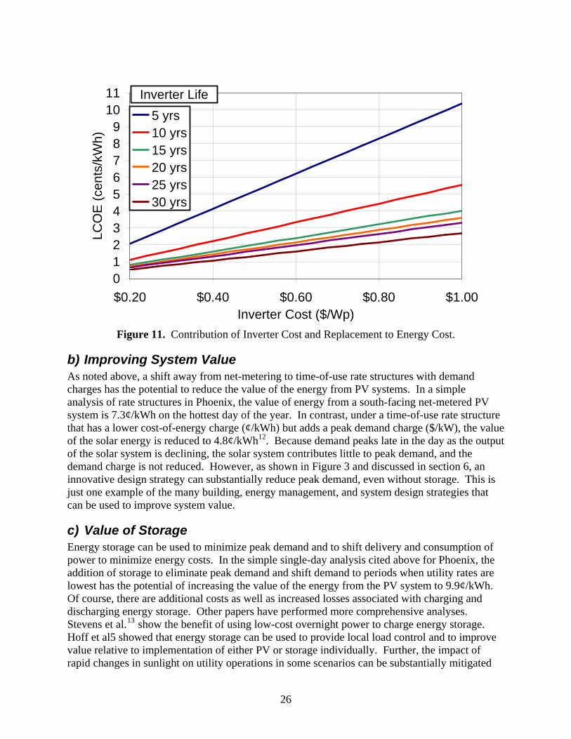
a) Reducing Inverter Cost The cost of inverters for simple net-metered systems is declining as production volumes increase. However, as penetration of PV into the distribution systems increases and rate structures change, the inverter and related-subsystems must become more complex in order to increase the value of energy relative to a simple, net-metered system. Thus, within the SEGIS program, there will be a need to use some of the advanced approaches outlined at the end of Section 6 to hold costs down even as the systems become more complex. System reliability is also important to cost reduction, especially for residential systems. For example, a 2-kW residential system in a sunny location will produce about 4000 kWh/yr. If that energy has a value of 10¢/kWh, then the value of the energy from the system is $400/yr. It is easy to see that a $100 annual service call would significantly reduce the value of the system. If an inverter cannot be repaired, but must be replaced, then the impact on system value is even greater. As shown in Figure 10, there is a tradeoff between system cost and system lifetime. Using standard economic assumptions from the DOE solar Multi-Year Program Plan11 for interest, inflation and tax rates, an inverter on a residential system in Phoenix with a 30 year lifetime and a cost of $1.00/Wp contributes 2.7¢/kWh to the cost of energy. In contrast, an inverter which lasted only ten years and thus had to be replaced twice over the life of a system will also contribute 2.7¢/kWh to the cost of energy if the inverter cost is only $0.50/Wp.12 If an inverter is to contribute no more than 1¢/kWh to the cost of energy in a sunny location like Phoenix, then the cost of the inverter must be less than $0.40/Wp if it lasts the life of the system (thirty years). If the inverter has a shorter lifetime, then the cost must be even less. As SEGIS inverter/controllers become more capable and complex to improve system value, reducing first cost and improving reliability will both be critical to achieving higher value.
25
0123456789
1011
$0.20 $0.40 $0.60 $0.80 $1.00Inverter Cost ($/Wp)
LCO
E (c
ents
/kW
h)5 yrs10 yrs15 yrs20 yrs25 yrs30 yrs
Inverter Life
Figure 11. Contribution of Inverter Cost and Replacement to Energy Cost.
b) Improving System Value As noted above, a shift away from net-metering to time-of-use rate structures with demand charges has the potential to reduce the value of the energy from PV systems. In a simple analysis of rate structures in Phoenix, the value of energy from a south-facing net-metered PV system is 7.3¢/kWh on the hottest day of the year. In contrast, under a time-of-use rate structure that has a lower cost-of-energy charge (¢/kWh) but adds a peak demand charge ($/kW), the value of the solar energy is reduced to 4.8¢/kWh12. Because demand peaks late in the day as the output of the solar system is declining, the solar system contributes little to peak demand, and the demand charge is not reduced. However, as shown in Figure 3 and discussed in section 6, an innovative design strategy can substantially reduce peak demand, even without storage. This is just one example of the many building, energy management, and system design strategies that can be used to improve system value.
c) Value of Storage Energy storage can be used to minimize peak demand and to shift delivery and consumption of power to minimize energy costs. In the simple single-day analysis cited above for Phoenix, the addition of storage to eliminate peak demand and shift demand to periods when utility rates are lowest has the potential of increasing the value of the energy from the PV system to 9.9¢/kWh. Of course, there are additional costs as well as increased losses associated with charging and discharging energy storage. Other papers have performed more comprehensive analyses. Stevens et al.13 show the benefit of using low-cost overnight power to charge energy storage. Hoff et al5 showed that energy storage can be used to provide local load control and to improve value relative to implementation of either PV or storage individually. Further, the impact of rapid changes in sunlight on utility operations in some scenarios can be substantially mitigated
26
with just fifteen minutes of storage capacity.1 Note that storage options are not limited to electric storage. Among load-side storage options are ice-based air conditioning systems and electric hot water heating. In any case, the capital cost, efficiency, lifetime, and maintenance costs of energy storage must be considered in the analysis and system design.
d) Models for Characterization of Performance and Cost of Energy Fully evaluating the benefits of a SEGIS system requires modeling of solar energy production, building loads, and energy storage relative to capital cost, maintenance, and the real-time cost of alternate energy sources (utility power). At this time, no single model will perform this analysis, but there are several that can be helpful. The Solar Advisor Model14 is used to conduct parametric analysis of system designs and to calculate performance and levelized cost of energy. Planned improvements to the Solar Advisor Model will support analysis of the value of systems with storage in a time-of-use rate structure. HOMER15 can be used to analyze solar energy production and energy storage. PVDesignPro16 is a commonly-used commercial model for analysis of solar system designs. Building energy analysis models, such as BEOpt17 and Energy-1018 may be helpful in understanding building energy demand and use of energy management systems.
9) Conclusions The SEGIS program is intended to provide the impetus for improving the methodologies and hardware for increasing the penetration of PV systems into the utility grid. The development of advanced, integrated inverter/controllers and associated energy management functions is a critical part of the SEGIS program. The SEGIS program is an aggressive effort to enable substantial penetration of PV into today’s grid, into intermediate grid scenarios, and into the smart grid of the future, which will be characterized by a significantly larger amount of distributed generation, much of it from intermittent sources. To achieve optimum value and to enhance the reliability of power for solar systems owners and the grid as a whole, these systems will require advanced controls that can integrate energy management and energy storage. Changes to the protection methods for the integrated grid will be required to accommodate the possible back-feeding of energy from these sources, and distributed generation systems will be required to demonstrate value in a market dominated by time-of-use tariffs. Advanced inverter/controllers and energy management systems will need to include sophisticated interfaces and controls to be able to integrate with emerging “Smart Grid” technology, and as such, must be compatible with communication protocols utilized by established and emerging energy management and utility distribution level communication systems. Finally, these systems must meet the performance and reliability targets consistent with achieving levelized cost of energy that will be competitive in future energy markets.
27

Bibliography
1. 2008 National Electrical Code, ANSI/NFPA70, Published by the National Fire
Protection Association, Quincy, MA, 2007. 2. King et al, “Performance Model for Grid-connected Photovoltaic Inverters,” Sandia
National Laboratories Report, SAND2007-5036, September 2007. 3. DOE Advanced Integrated Inverter and Energy Management – Technical Workshop
Presentations, April 19, and May 10-11, 2007, Denver, CO and Santa Ana Pueblo, NM http://www2.eere.energy.gov/solar/solar_america/technology_pathway_partnerships_wkshp.html
4. Summary Report on the DOE High-tech Inverter Workshop, Jan, 2005, http://www1.eere.energy.gov/solar/pdfs/inverter_II_workshop.pdf
5. Galvin Electricity Initiative, “The Path to Perfect Power – The Perfect Power System,” 2007, http://www.galvinpower.org/galvinpower.pdf
6. 2005 NEC Handbook, NFPA70, Published by the National Fire Protection Association, Quincy, MA, 2005.
7. Ton, D., Bulawka, A., Bower, W., Summary Report on the DOE Workshop On a Systems-driven Approach To Inverter Research and Development, U.S. Department of Energy, EERE Solar Technology Program, http://www1.eere.energy.gov/solar/pdfs/sda_inverter.pdf Sep 2003.
8. Bower, W., Ropp, M., “Evaluation of Islanding Detection Methods for Photovoltaic Utility-interactive Power Systems”, International Energy Agency Photovoltaic Power Systems Implementing Agreement, Task V; Grid Interconnection of Building-integrated and Other Dispersed Photovoltaic Power Systems, Report IEA PVPS T5-09: 2002, Feb. 2002.
9. Lee, F.C., Van Wyk, J.D., Boroyevich, D., Jahns, T., Lorenz, R.D., Chow, T.P., Gutmann, R.J., Barbosa, P., An Integrated Approach to Power Electronics Systems, Report for National Science Foundation, 2002.
10. UL Standard for Safety for Static Converters and Charge Controllers for Use in Photovoltaic Power Systems, UL1741, Underwriters Laboratories, Second Edition, Jan 2001.
11. IEC 61683, Photovoltaic systems - Power conditioners - Procedure for measuring efficiency, International Electrotechnical Commission, Pub. Nov 1999.
12. Beyond the “Balance of System - Growing Value of Solar Installations”, Presented at Solar Power 2006, San Jose, CA, Sep 2006.
13. ISET – Advancing Energy Systems, 2006 Annual Report, Institute for Solare Energieversorgungstechnik, Kassel, Germany
28
29
References
1 Henry, B., “Utility Needs for Advanced Intelligent Inverters,” Proceedings of the DOE Advanced Integrated Inverter and Energy Management – Technical Workshop, Santa Ana Pueblo, NM, May 10-11, 2007, http://www2.eere.energy.gov/solar/solar_america/pdfs/8_bill_henry_presentation_051007.pdf . 2 Horgan, S., “Distributed Utility Integration Test (DUIT): Facility and Unintentional Islanding Results,” Presented at the US DOE High-tech Inverter Workshop, April, 2004. 3 Barker et al., “Renewable Systems Integration: Report 1, Advanced Grid Planning and Operation,” Electric Power Research Institute, Draft October 2007. 4 USDOE, U.S. Department of Energy (1999). Making the Most of Residential Photovoltaic Systems, DOE/GO 10099-918, September 1999. 5 Hoff et al., “Maximizing the Value of Customer-sited PV Systems Using Storage and Controls,” Proceedings of the 2005 Solar World Congress, Orlando, FL, Aug 2005. 6 Newmiller, et.al, “Distributed PV Systems Design and Technology Requirements,” RSI Study Report, BEW Engineering, October 2007 7 S&C Electric Company, PureWave UPS System, http://www.sandc.com/products/purewave/default.asp 8 McIntyre, A. “Renewable Systems Interconnection Security Analysis,” Sandia National Laboratories, draft, September, 2007. 9 Newmiller, et al. “Distributed PV Systems Design and Technology Requirements,” BEW Engineering, Draft, October, 2007. 10 Burger et al., “Photovoltaic Inverters with SiC MOSFETs,” Fraunhofer Institute for Solare Energy Systems (ISE), Freiburg, Germany, presented at 2nd ECPE SiC User Forum, Copenhagen, September 6-7, 2007. 11 “Solar Energy Technologies Program Multi-Year Technical Plan, 2007-2011,” U.S. Department of Energy, http://www1.eere.energy.gov/solar/pdfs/set_myp_2007-2011_proof_1.pdf 12 Cameron, C.P., “Impacts of Advanced Inverter Lifetimes and Reliability on Levelized Cost of Energy,” Proceedings of the DOE Advanced Integrated Inverter and Energy Management – Technical Workshop, Santa Ana Pueblo, NM, May 10-11, 2007, http://www2.eere.energy.gov/solar/solar_america/technology_pathway_partnerships_wkshp.html 13 Stevens, J.W. et al, “Performance of a grid connected residential photovoltaic system with energy storage”, SAND97-2742C, http://infoserve.sandia.gov/sand_doc/1997/972742c.pdf 14 Solar Advisor Model (SAM), NREL, http://www.nrel.gov/analysis/sam/ 15 HOMER – The Optimization Model for Distributed Power, NREL, http://www.nrel.gov/homer/ 16 PVDesignPro, Maui Solar Software, http://www.mauisolarsoftware.com/ 17 Christensen et al, BEOpt, Software for Identifying Optimal Building Designs on the Path to Zero Net Energy, Presented at the ISES Solar World Congress, Orlando, FL, Aug 6-12, 2005. 18 Energy-10 – Software tool for Architects, Builders and Engineers, NREL, http://www.nrel.gov/buildings/energy10.html


![Solar Forecasting: Maximizing its value for grid ... · Solar Forecasting: Maximizing its value for grid integration Introduction ... [Brancucci Martinez-Anido 2016]. Both challenges](https://img.dokumen.tips/doc/110x75/5b94d71b09d3f2a65f8de065/solar-forecasting-maximizing-its-value-for-grid-solar-forecasting-maximizing.jpg)


