Embed Size (px)
Citation preview

Enhancing Modelica towards variable structure systems
Author: Dirk Zimmer ETH Zürich, Institute of Computational Science, Department of Computer Science
ECOOL 2007, Berlin
SOLAn object-oriented modeling language
for variable structure systems.
SOL

© Dirk Zimmer, July 2007, Slide 2
Department of Computer ScienceInstitute of Computational Science
ETH Zürich
• Motivation
• Modeling concept
• Presentation of Sol– Fundamentals
– Model hierarchy and type-system
– Implementation: Equations and transmissions
• Example 1: Switch of the engine model
• Current state of the implementation and Outlook
• Example 2: Pendulum with a structural change
Overview

© Dirk Zimmer, July 2007, Slide 3
Department of Computer ScienceInstitute of Computational Science
ETH Zürich
• Many contemporary models contain structural changes at run time:– ideal switching processes.– variable number of entities or agents.– variable level of detail.– user interaction.
• A general modeling language supporting variable structure systems offers a number of important benefits.
• Modelica is very limited in this respect. The limitations originate from technical points of view and from a lack of expressiveness.
• MOSILAB offers a first approach to handling variable structure systems in a more general sense.
Motivation I

© Dirk Zimmer, July 2007, Slide 4
Department of Computer ScienceInstitute of Computational Science
ETH ZürichMotivation II
• We took a rather fundamental approach and decided to develop a new language: Sol. The motivation behind this project is twofold:
• One, Sol shall offer a platform for the development of corresponding technical solutions. This concerns…
• dynamic recausalization• dynamic treatment of higher index problems• etc…
• Two, Sol is a language experiment. We want to explore the full power of a declarative modeling approach and how it can handle potential, future problem fields.
• Sol is not a product! We don’t intend to throw another modeling language or dialect on the market. Sol is primarily a tool to enable principal research on the subject of variable structure systems.

© Dirk Zimmer, July 2007, Slide 5
Department of Computer ScienceInstitute of Computational Science
ETH ZürichModeling concepts
• Sol attempts to be a language of minimal complexity
• Sol redefines the fundamental concepts of Modelica on a dynamic basis.
• Sol enables the creation, exchange and destruction of components at simulation time.
• To this end, the modeler describes the system in a constructive way, where the structural changes are expressed by conditionalized declarations. These conditional parts can then get activated and deactivated during run-time.
• The constructive approach avoids an explicit description of modes and transitions and yet proves to be fairly powerful.
• The following slides provide an informal and incomplete introduction to Sol.

© Dirk Zimmer, July 2007, Slide 6
Department of Computer ScienceInstitute of Computational Science
ETH ZürichSol: Fundamental entity
• A model is the essential language element in Sol. It is of very general use and consists always of three optional parts:
• The header: Here you can define constants or specify inheritances or include sub-models.
• The interface: parameters and variables that are visible from outside are specified in the interface section.
• The implementation describes the actual relations between the variables and introduces the dynamics.
model myFirst
define minute as 60;
interface:parameter Real tau << 1;parameter Real sat << 1;static Real x;
implementation:static Real v;when initial then
x = 0;end
v = der(x);x = (sat-x)*(tau/minute);
end myFirst;

© Dirk Zimmer, July 2007, Slide 7
Department of Computer ScienceInstitute of Computational Science
ETH ZürichSol: Hierarchy and inheritance
• Sol enables the hierarchic organization of models within models (e.g. packages)
• Sol offers means for type-generation like model-extension (extends), model-redefinitions (redefine) or variable-redeclarations (redeclare).
• These mechanisms can be applied to complete packages as well.
package Mechanics
package Interfaces
connector Frameinterface:
static potential Real x;static flow Real f;
end Frame;
model OnePortinterface:
static Frame f;end OnePort;
model TwoPortinterface:
static Frame fa;static Frame fb;
end TwoPort;
end Interfaces;
model Body extends Interfaces.OnePort;interface:
parameter Real m;end Body;
model Prismatic extends Interfaces.TwoPort;interface:
parameter Real s;…
…

© Dirk Zimmer, July 2007, Slide 8
Department of Computer ScienceInstitute of Computational Science
ETH Zürich
Executing…solsim TestStruct.sol -o out.dot –struct
dot -Tps out.dot -o out.ps
produces a graph of the model hierarchy
Sol: Hierarchy and inheritance

© Dirk Zimmer, July 2007, Slide 9
Department of Computer ScienceInstitute of Computational Science
ETH Zürich
package Mechanics
package Interfaces
connector Frameinterface:
static potential Real x;static flow Real f;
end Frame;
model OnePortinterface:
static Frame f;end OnePort;
model TwoPortinterface:
static Frame fa;static Frame fb;
end TwoPort;
end Interfaces;
model Body extends Interfaces.OnePort;interface:
parameter Real m;end Body;
model Prismatic extends Interfaces.TwoPort;interface:
parameter Real s;…
…
Sol: Type-system
• Like Modelica, Sol features a structural type system. Thus, separate lines of implementation can be compatible.
• The type is defined in the interface-section (except for the extensions).
• Redeclarations or redefinitions must provide sub-types of their original representation.

© Dirk Zimmer, July 2007, Slide 10
Department of Computer ScienceInstitute of Computational Science
ETH ZürichSol: Type-system
Executing…solsim TestStruct.sol -o out.dot –types
dot -Tps out.dot -o out.ps
produces a graph of the type hierarchy

© Dirk Zimmer, July 2007, Slide 11
Department of Computer ScienceInstitute of Computational Science
ETH ZürichSol: Model-Implementation
• The implementation consists of a block.
• A block may contain…– declarations of variables or model-instances
– equations or transmissions
– nested (conditional) blocks

© Dirk Zimmer, July 2007, Slide 12
Department of Computer ScienceInstitute of Computational Science
ETH ZürichSol: Member-access
• At the declarations the identifier is linked either statically or dynamically to its model-instance.
• Members of an instance can be accessed through
– The . operator
– A connection statement
– The ( ) operator
• Instances can be anonymously declared.
model Sinusinterface:
static Real x;static out Real y;
implementation:…
end Sinus;
implementation:static Sinus s;
//1st variant
s.x = u;s.y = v;//2nd variant (silly here)
connection(s.x,u);connection(s.y,v);//3rd variant
v = s(x=u);
v = Sinus(x=u);

© Dirk Zimmer, July 2007, Slide 13
Department of Computer ScienceInstitute of Computational Science
ETH ZürichSol: Statements
• Sol provides 3 operators for setting up relations– equation (=)– causal copy-transmission (<<)– causal move-transmission (<-)
• The transmission operators can be applied to model-instances.
• Dynamic instances can be created by transmitting anonymous declarations to a dynamically-linked identifier. Moving to the trash deletes instances.
parameter Real R;static Real u;static Real i;
u = R*i;
static Boolean open;open << false;
dynamic Resistor currentR;currentR <- HeatResistor{R<<100};
trash <- currentR;

© Dirk Zimmer, July 2007, Slide 14
Department of Computer ScienceInstitute of Computational Science
ETH ZürichSol: Branches
• Sol features if-else-branches and when-else-branches.
• If-branches are evaluated during an update-step.
• When branches are evaluated at the end of an update-procedure and their contents gets activated for the next update procedure.
• There are no syntactical restrictions on the content of the branches.
model Gain
interface:parameter Real gf;static out Real g_out;static Real g_in;
implementation:static Real h ;h << gf * g_in;
if h < 0.5 theng_out << Gain(g_in << h);
else theng_out << h;
end;
end Gain;

© Dirk Zimmer, July 2007, Slide 15
Department of Computer ScienceInstitute of Computational Science
ETH ZürichExample 1
• Let us model a simple machine, consisting of an engine that drives a fly-wheel.
• Two models are provided for the engine:
– The first model “Engine1” applies a constant torque on the flange.
– In the second model “Engine2”, the torque is dependent on the positional state similar to a piston-engine.
• The machine-model connects the engine and the fly-wheel. It contains a structural change that is reflected by a substitution of the engine-models.
• Initially, the fly-wheel is at rest, and the more complex engine model is used. When the speed exceeds a certain threshold, it seems appropriate to average the torque. Thus, the simpler engine-model is used instead.
• The example in the paper (shown in the next slides) had to be adapted to the current state of implementation.

© Dirk Zimmer, July 2007, Slide 16
Department of Computer ScienceInstitute of Computational Science
ETH ZürichExample 1model FlyWheelinterface:
parameter Real inertia << 1;static Flange f;static Real w;
implementation:static Real z;w = der(f.phi);z = der(w);f.t = inertia*z;when initial then w=0; f.phi=0; end;
end FlyWheel;
model Machine implementation:
static FlyWheel Wheel1{inertia<<10};static Boolean fast;if fast thenstatic Engine1 E{meanTorque<<100}; connection(E.f,Wheel1.f);
else thenstatic Engine2 E{meanTorque<<100};connection(E.f,Wheel1.f);
end;when initial then fast<<false; end;when Wheel1.w > 50 then fast<<true; end;
end Machine;
connector Flangeinterface:
static potential Real phi;static flow Real t;
end flange;
partial model Engineinterface:
parameter Real meanTorque<<1;static Flange f;
end Engine;
model Engine1 extends Engine;implementation:
f.t = meanTorque;end Engine1;
model Engine2 extends Engine;implementation:
static Real transm;transm = 1+sin(f.phi);f.t = meanTorque*transm;
end Engine2;

© Dirk Zimmer, July 2007, Slide 17
Department of Computer ScienceInstitute of Computational Science
ETH ZürichExample 1
model Machine
implementation:static FlyWheel Wheel1{inertia<<10};dynamic Engine E;connection(E.f,Wheel1.f);
when initial thenE <- Engine2{meanTorque << 100};
end;when Wheel1.w > 50 thenE <- Engine1{meanTorque << 100};
end;
end Machine;
• The previous model contained a separate branch for each mode. The transitions are modeled by when-statements.
• Here we present a second variant, where the model-instance is dynamically linked to the identifier.
• The corresponding update of the connection statement is treated automatically by the system.

© Dirk Zimmer, July 2007, Slide 18
Department of Computer ScienceInstitute of Computational Science
ETH ZürichExample 1: Results
Executing…solsim TestEngine.sol -o out.dat -sim 10 0.001
pgnuplot results.gnu
simulates through 10’000 Euler steps and draws a plot of the angular velocity
0 1 2 3 4 5 6 7 8 9 100
10
20
30
40
50
60
7.5 7.55 7.6 7.65 7.7 7.75 7.8
39
39.5
40
40.5
41

© Dirk Zimmer, July 2007, Slide 19
Department of Computer ScienceInstitute of Computational Science
ETH Zürich
The program solsim is an interpreter
1. The model-textfile is parsed and mapped on the internal data-structures.
2. The type generation is processed (extensions, redefinitions..).
3. The relevant model-instances are created.
4. The corresponding transmissions (and equations) are dynamically flattened and ordered.
5. The dynamically flattened system is then evaluated.
6. The evaluation of branch-statements may lead to further instantiations or to the deletion of existing instances.
7. Thus, a structural change leads to an update (not rebuild) of the dynamically flattened system.
8. The evaluation continues until the end of the simulation.
Current Implementation

© Dirk Zimmer, July 2007, Slide 20
Department of Computer ScienceInstitute of Computational Science
ETH ZürichOutlook
The current implementation is still in an early stage and represents only an intermediate solution. Our future work will focus on…
• The dynamic causalization processes
• The dynamic handling of higher-index problems
• The inclusion of arrays
• Well-specified handling of discrete events
• Strict and formal presentation of the language
• Development of optimization schemes.
Obviously we have now a large playground for our research.
© Dirk Zimmer, July 2007, Slide 21
Department of Computer ScienceInstitute of Computational Science
ETH Zürich2nd Example
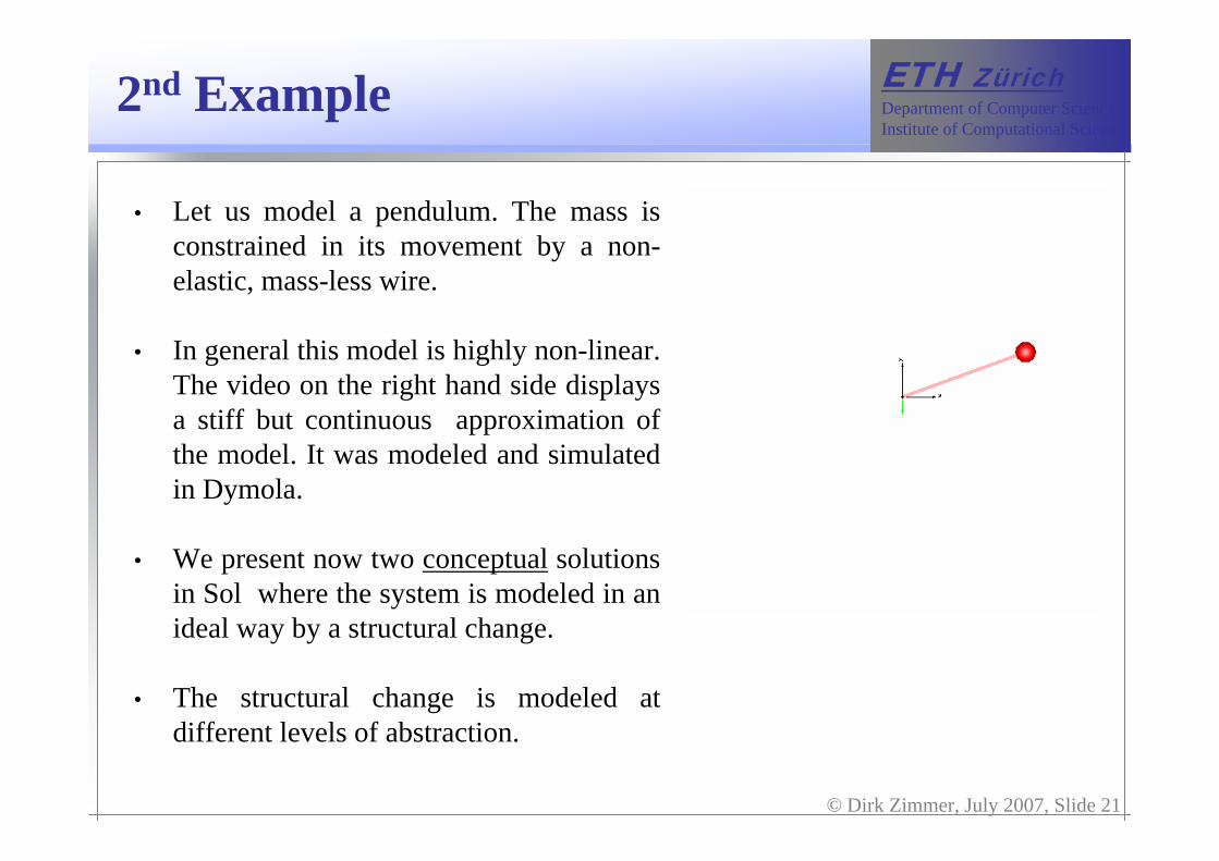
• Let us model a pendulum. The mass is constrained in its movement by a non-elastic, mass-less wire.
• In general this model is highly non-linear. The video on the right hand side displays a stiff but continuous approximation of the model. It was modeled and simulated in Dymola.
• We present now two conceptual solutions in Sol where the system is modeled in an ideal way by a structural change.
• The structural change is modeled at different levels of abstraction.

© Dirk Zimmer, July 2007, Slide 22
Department of Computer ScienceInstitute of Computational Science
ETH Zürich
model WirePendulum
interfaceparameter Real l;static Real[2] x;static Real[2] v;
implementation:static Boolean free;
if free thenstatic Body b{x_start<<x,
v_start<<v};when dist(a=fa.x, b=fb.x) >= lthen
free << false;x << b.x;v << b.v;
end;…
2nd Example: 1st Version
…else then
static Fixed fix{x << [0,0]};static Body b{};static Revolute{w_start<<f(v),
phi_start<<g(x)}static Translation{n<<[l,0]}connection(fix.f,R.fa);connection(R.fb,T.fa);connection(T.fb,b.f );
when (x=T.f*T.r) <= 0 thenfree << true;x << b.x;v << b.v;
end;
end;
when initial thenfree << true;x << 0.4; y << 1.0;
end;
end WirePendulum
In the first version, the structural change is modeled at the top level.

© Dirk Zimmer, July 2007, Slide 23
Department of Computer ScienceInstitute of Computational Science
ETH Zürich
model WirePendulum2interface:
parameter Real l;static Real[2] x;
implementation:static Fixed f;static Revolute r;static LimitedPrismatic p;static Body b;
connection(f.f,r.fa);connection(r.fb,p.fa);connection(p.fb,b.f);
end FreePendulum2
2nd Example: 2nd Version
• The first version simply models a transition between two separate models.
• However, this transition is non-physical. The actual force-impulse is not taken into account.
• The second variant (on the right) does not contain a structural change at the top-level. It must be in one of the sub-models.
• Let us examine the sub-models…
© Dirk Zimmer, July 2007, Slide 24
Department of Computer ScienceInstitute of Computational Science
ETH Zürich
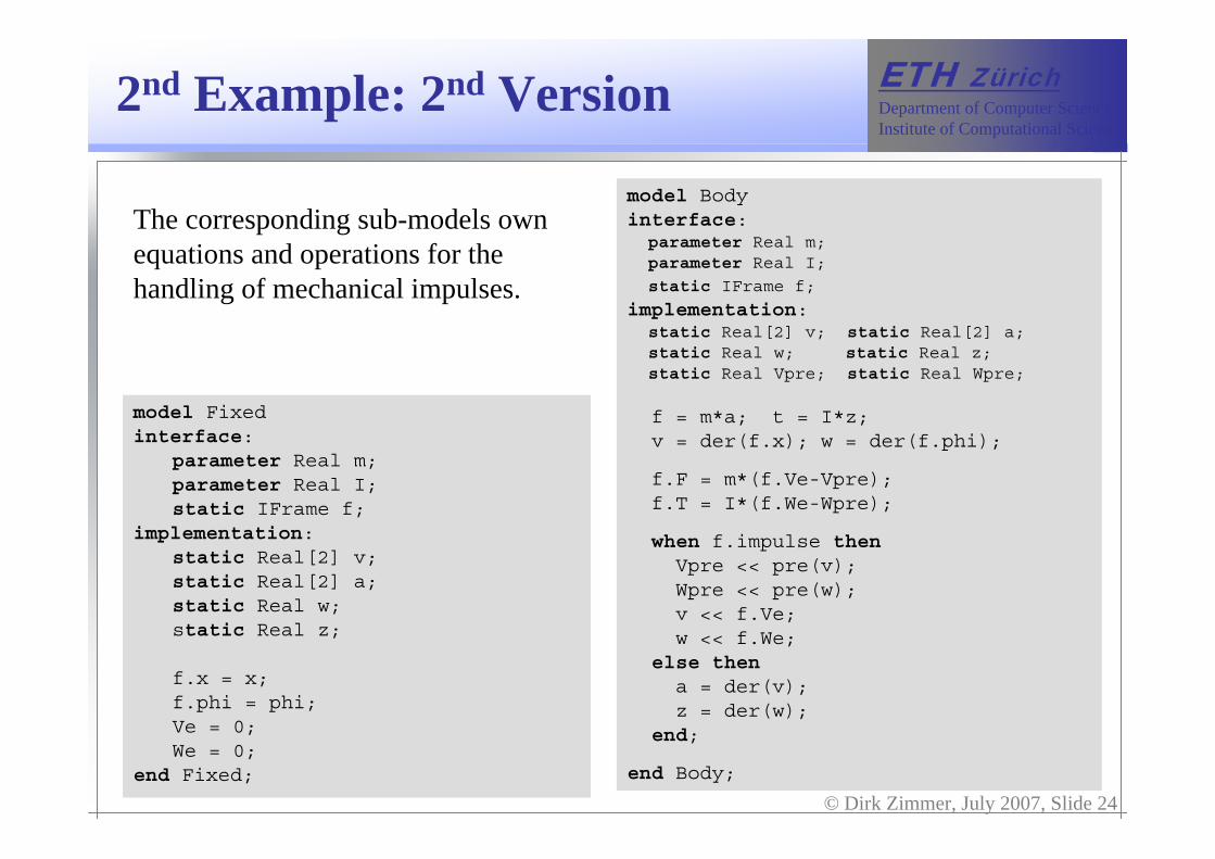
model Body interface:
parameter Real m;parameter Real I;
static IFrame f;
implementation:static Real[2] v; static Real[2] a;static Real w; static Real z;static Real Vpre; static Real Wpre;
f = m*a; t = I*z;v = der(f.x); w = der(f.phi);
f.F = m*(f.Ve-Vpre);f.T = I*(f.We-Wpre);
when f.impulse thenVpre << pre(v);Wpre << pre(w);v << f.Ve;w << f.We;
else thena = der(v);z = der(w);
end;
end Body;
2nd Example: 2nd Version
model Fixedinterface:
parameter Real m;parameter Real I;static IFrame f;
implementation:static Real[2] v; static Real[2] a;static Real w;static Real z;
f.x = x;f.phi = phi;Ve = 0;We = 0;
end Fixed;
The corresponding sub-models own equations and operations for the handling of mechanical impulses.

© Dirk Zimmer, July 2007, Slide 25
Department of Computer ScienceInstitute of Computational Science
ETH Zürich
model LimitedPrismaticinterface:
parameter Real l;parameter Real[2] n;static Real s;static Real v;static Real a;static frame fa;
static frame fb;
implementation:static Boolean free;
static Real[2] r;r[1]=n[1]*sin(fa.phi)+n[2]*cos(fa.phi);r[2]=n[2]*sin(fa.phi)-n[2]*cos(fa.phi);fb.x = fa.x+s*r;fa.phi = fb.phi;a = der(v);fa.t = cross(r*s,fb.f) + fb.t; fa.f + fb.f = 0;
fa.We = fb.Wb;fa.Ve = fb.Ve + cross(r*s,fa.We);fa.F + fb.F = [0,0]:
fa.T = cross(r*s,fb.F) + fb.T = 0;
2nd Example: 2nd Version
if free thenfa.f*r = 0;when dist(a=fa.x, b=fb.x) >= lthenfa.impulse << true;fa.impulse << true;
end;else thens = l;when (fa.f-fb.f)*r*sign(x=s) < 0then free << true; end;
end;
when fa.impulse thenfree << false;(fa.Ve - fb.Ve)*r = 0;v = 0;fa.impulse << false;fa.impulse << false;
else thenfa.F*r = 0;v = der(s);
end;
end LimitedPrismatic

© Dirk Zimmer, July 2007, Slide 26
Department of Computer ScienceInstitute of Computational Science
ETH Zürich2nd Example: Conclusions
• In the second version, the structural change was modeled in the limited joint and involves a force-impulse.
• The second version is a truly object-oriented solution. However, it is more demanding with respect to the simulator’s capabilities (dynamic handling of index-changes, etc. ).
• Consider the task where you want to extend your model to a double-pendulum of the same kind. The first approach reveals to be a dead-end whereas the second one can easily be extended.
• However, important is that both approaches shall be possible in Sol.

© Dirk Zimmer, July 2007, Slide 27
Department of Computer ScienceInstitute of Computational Science
ETH Zürich2nd Example: Conclusions
• None of the two variants is per se the better one. The decision between different variants depends on the current task and can only be made by the modeler.
• Thus, a general modeling language shall attempt to refrain from enforcing modeling-decisions. It should only provide the elementary means and let the modeler compose his solution out of them.
The End