Embed Size (px)
Citation preview

ManualSoil-In (C parameters calculation)

Chapter 1
Table of Contents
Manual 1
Table of Contents 2
Introduction 3
Support on surface 5
Subsoil in the 3D model 7
Required parameters for Soil-in calculation 16
Soil-in calculation 18
The results of soil-in 23
Soil-in and Pile design 30
Advanced tips 31
- 2 -

Introduction
IntroductionTheanalysis of foundation structures is challengedby theproblem of modellingof thepart of the foundation that is in contact withsubsoil. Thebest solution is to use2Dmodel of the subsoil that properly represents thedeformationproperties of thewhole under-foundationmassif by means of surfacemodel. Theproperties of suchmodel areexpressedby what is called interactionparametersmarkedC. Theseparameters areassigneddirectly to structure elements that are in contact with the subsoil and they influence thestiffness matrix.
To simplify thematter, wemay imagine that C is the characteristics of elastic, moreprecisely pseudo-elastic, links, or surfacespring constants that changeaccording to theactual state of theanalysed system. Wemay alsouse theprofessional slang thatcalls it "support onC parameters", which is thegeneralisationof standardWinkler ideaof the supporting in the form of thick liquid g=C1 (MNm-3) or in the form of infinitely densesystem of vertical springs. Thegeneralisation is very important anddeals mainly withthe considerationof significant shear distribution in the subsoil that is neglectedbyWinklermodel. Theparameters of the interactionbetween the foundationand the subsoil depends on thedistributionand loading level, or the contact stress between the structure sur-faceand the surrounding subsoil, on thegeometry of the footing surfaceandonmechanical properties of the soil.
CalculationmoduleSoil-in takes account of all thementioneddependencies.
As theC parameters influence the contact stress andvice versa– thedistributionof the contact stress have impact on the set-tlement of the footing surfaceand thus theC parameters, it is necessary to usean iterative solution.
The influence of subsoil in the vicinity of the structureThemodellingof the interactionbetweenastructure andsubsoil requires that the influenceof the subsoil outsideof the structure betaken into account. This outside-subsoil supports theedges of the foundation slabdue to shear stiffness. In thepast, special pro-cedures were recommended tomodel this phenomenon. Thecurrent versions of SciaEngineer employ a sophisticated solutionwhoseprinciple is described in the followingparagraph.
Theprogram automatically adds to theedgeof theanalysed foundation slab springs that approximately substitute theeffect of whatis termedsupport elements (1 to 2metrewide strip locatedalong theedges of the foundation slab, the thickness of this strip isalmost zero). Thesolutionobtained through this approach takes into account theeffect of the subsoil outside (in the vicinity) of theanalysed foundation slab.
In comparisonwith a solutionwithout such springs, the results obtainedwith the springs gives smaller deformationof the foun-dation-slabedges whichmeans larger bendingmoments in the foundation slab.
Thesprings oriented in theglobal z-directionareassigned toall edgenodes except the situationwhenanodealready has anotherspringassignedor if a rotationof a node is specified. In that case, theprogram assumes that theuser has already definedaspecialtypeof support and that it is not wanted to alter that special configurationautomatically on thebackground.
Theseexceptions canbeused todeliberately suppress the implementationof edge-springs along certain lines. Theuser candefinevery small line springs along required lines (edges) and thus eliminate theeffect of the surrounding subsoil (e.g. if a sheet pilewall isinstalled).
Soil-in outputThe results from the soil-in iterationare theC parameters C1z, C2x andC2y.
Parameters C1x andC1y arealways definedby theuser.
C1z - resistanceof environment against wP (mm) [C1z inMN/m3]
C2x - resistanceof environment against wP/xP (mm/m) [C2x inMN/m]
C2y - resistanceof environment against wP/yP (mm/m) [C2y inMN/m]
- 3 -

Chapter 1
C1x - resistanceof environment against uP (mm) [C1x inMN/m3]
C1y - resistanceof environment against vP (mm) [C1y inMN/m3]
Note: Usually, C2x is consideredequal toC2y andC1x equal toC1y, because the calculation is doneby so called iso-tropic variant of the calculationof C2parameter.
Thesoil-in calculation is availablewhen the specific functionality is active.
Check Subsoil on the left part and theSoil interactionon the right part of the functionality tab:
Note: TheSoil interaction is available only for PlateXY andGeneral XYZ typeof project.
- 4 -
Support on surface
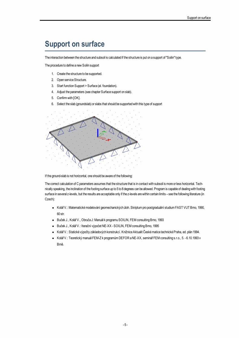
Support on surfaceThe interactionbetween the structure andsubsoil is calculated if the structure is put onasupport of "Soilin" type.
Theprocedure to defineanewSoilin support
1. Create the structure to be supported.2. OpenserviceStructure.3. Start functionSupport > Surface (el. foundation).4. Adjust theparameters (see chapter Surface support on slab).5. Confirmwith [OK].6. Select the slab (groundslab) or slabs that should be supportedwith this typeof support
If theground-slab is not horizontal, one should beawareof the following:
Thecorrect calculationof C parameters assumes that the structure that is in contact with subsoil is moreor less horizontal. Tech-nically speaking, the inclinationof the footing surfaceup to5 to 8degrees canbeallowed. Program is capable of dealingwith footingsurface in several z-levels, but the results areacceptable only if the z-levels arewithin certain limits – see the following literature (inCzech):
l Kolář V.: Matematickémodelování geomechanickýchúloh. Skriptum propostgraduální studiumFAST VUT Brno, 1990,
60 str.l Buček J., Kolář V., Obruča J: Manuál k programuSOILIN, FEM consultingBrno, 1993l Buček J., Kolář V.: Iterační výpočet NE-XX - SOILIN, FEM consultingBrno, 1995l Kolář V.: Statické výpočty základových konstrukcí. KnižniceAktualit Českématice technickéPraha, ed. plán1994.l Kolář V.: Teoretický manuál FEM-Z k programůmDEFOR aNE-XX, seminář FEM consulting s.r.o., 5. - 6.10.1993v
Brně.
- 5 -

Chapter 2
The surface support properties
Name: Specifies thenameof the support.
Type: Defines the typeof support – seebelow.
Subsoil: If necessary for the selected type, this item specifies the subsoil parameters.
Type
Individual:A particular subsoil type is assigned to the slab.Thesubsoil is definedby means of C parameters. Theseuser-definedC parameters areused for the calculation (of e.gcontact stress in the footing surface)
Soil-in:For suchasupport, the interactionof the structurewith the foundation subsoil is carriedout by means of SOIL-INmodule.Parameters C1z, C2x, C2y are calculatedby SOIL-INmodule.
Both:Bothof theabovementioned types are combinedon the sameslab.Theuser defines whichC parameters will beuser-definedandwhichones will be calculatedby SOIL-INmodule.
Parameters canbedefined in subsoil properties. ThoseC parameters that are input in the subsoil-property dialogueas zero, will becalculatedby theSOIL-INmodule. Nonzeroparameters will be takenas they are input.
- 6 -

Subsoil in the3Dmodel
Subsoil in the 3D modelThesubsoil in the3Dwindow is definedas asoil surfaceandsoil borehole. Thegeologic profile is defined for each soil borehole. Thepositionand the compositionof thegeologic profiles provide informationabout subsoil.
Soil boreholeTheborehole is available in theproject only when the functionality Soil interaction is checked.
Geologic profile
All profiles are saved to theGeologic profiles library. Thegeologic profiles canbe importedor exportedby theDB4 format.
Theborehole profile is definedas asimple gridwith thepreview. Each row represents one layer of soil with the sameproperties.
Each layer is definedby the soil parameters:
Name:Specify thenameof the layer
Thickness (m):thickness of the layer
Edef:
- 7 -

Chapter 3
Themodule of deformationEdef is definedas deformation characteristic of the soil. It is a ratio of thenormal stress incre-ment to the increment a linear transformation. For geotechnical categories 1and2 the indicative value from e.g. ČSN 731001canbeused, for category 3a survey should be carriedout to provide for the value.
Edef according toČSN 731001:
Class of the subsoil Edef (MPa)
F6-F8 (soft, medium consistency) 1,5-4
F6-F8 (stiff consistency) 6-8
F6-F8 (hard consistency) 10-15
F3-F5 (soft, medium consistency) 3-5
F3-F5 (stiff consistency) 8-10
F3-F4 (hard consistency) based on survey
F5 (hard consistency) 10-20
F1, F2 (soft, medium consistency) 5-15
F1, F2 (stiff consistency) 12-25
F1, F2 (hard consistency) based on survey
S4, S5 5-12
S3 12-19
S2 15-35
S1 30-60
G5 40-60
G4 60-80
G3 80-90
G2 100-190
G1 250-390
R6 10-75
R5 20-250
R4 40-750
R3 70-2500
R2 130-7500
R1 250-25000
TheEdef for R is derived from thenumber of discontinuous parts in the soil.
Poisson:Poisson’s ratio, coefficient of transversedeformation, an indicative valueor experimentally foundvalue canbeused,predefined range is 0–0.5
Poissonaccording toČSN 731001:
Class of the subsoil Poisson ν
F8 (soft, medium, stiff consistency) 0,42
F8 (hard consistency) based on survey
F5-F7 (soft, medium, stiff consistency) 0,40
- 8 -

Subsoil in the3Dmodel
Class of the subsoil Poisson ν
F5-F7 (hard consistency) based on survey
F1-F4 (soft, medium, stiff consistency) 0,35
F1-F4 (hard consistency) based on survey
S5 0,35
S4, S3 0,30
S1, S2 0,28
G4,G5 0,30
G3 0,25
G1,G2 0,20
R6 0,40-0,25
R4, R5 0,30-0,20
R3 0,25-0,15
R1, R2 0,20-0,10
Dry weight:weight for thedry soil, normally within the range from 18 to23kN/m3, range is 0–10000000000kN/m3
Wet weight:weight for thewet (saturated) soil, this value is mostly about 2-3 kN/m3 higher than thedry weight, rangeof the values is10–10000000kN/m3
m coefficient:structural strength coefficient, according to theEurocode7 is 0,2 (ČSN 731001definea table).
Coefficient m according toČSN 731001:
Class of the subsoil m
F1-F8 with Edef<4MPa, not over consolidated and soft or solid consistency
R1, R2 and R4, R5 not affected by erosion0,1
F1-F8 which don’t belong to the first group
S1, S2,G1,G2 under the water level
R3
0,2
S1, S2,G1,G2 above the water level
S3-S5
G3-G5
R4, R5 which don’t belong to the first group
0,3
R6 0,4
Loess, loess loam 0,5
Note: Geologic profilemust bedefinedup to suchadepthwhere thebearingpressure is still active, otherwise theprogramdoes not have sufficient information.
Thedefinedparameters aredisplayed in the library as properties.
- 9 -

Chapter 3
Theheight of theundergroundwater is definedby the value in theproperties. It is a positive valuebut it represents thedepth.
Non-compressible subsoil below the last inputted layer
Thecheckbox “Non-compressible…” canbeused if the soil below the last layer is non-compressible. Thesystem applies coef-ficient of depth reduction 2 in this case (calculationof 2 canbe found inČSN 731001, art. 80). This option is recommendedwhen thenon-compressible layer is placed in a small depthunder theborehole.
Calculationof 2 according toČSN 731001:
2=1-exp((zic/z) ln0,25+ ln0,8)
1– foundationbase
2–non-compressible layer
zic – is thedepthunder the foundationbase to thenon-compressible layer
z – is thedepth from the foundationbase to the level where the contact stress σz should be calculated
Thecontact stress σzwill be calculatedby the reduceddepth zr2= 2*z where z is thedepthunder the foundationbase.
- 10 -

Subsoil in the3Dmodel
Properties of the borehole profile
Theborehole is definedby thegeologic profile and the insertingpoint in the3Dwindow. Theproperties contain only name, its coor-dinates, theborehole profile and the checkbox Results only.
Settlement input data
Settlement is calculated for eachmeshelement (in its center of gravity) and for eachborehole insertingpoint. The checkboxResults only excludeaborehole insertingpoint from the input data. It means that thepoint is used for the calculationof settlementbut thegeologic profile is not taken into account for the layers approximation.
Thenodes for the settlement calculation (greenvertexes):
Layers approximation
Whenmoreborehole profiles areused in theproject then it must fulfil one important condition– the samenumber of layers. This isrequiredbecauseof the soil-in approximation.
- 11 -

Chapter 3
Note: If there is some layermissing in oneborehole, then it canbesubstitutedby layer withminimum thickness –e.g.1mm.o the soil-in has appropriate number of layers for approximation.
Foundation base
The level of the foundationbase is consideredon thebottom surfaceof theplate. Theeccentricities arealso taken into account.
Even theextrem exampleas this oneplace the foundationbase to thebottom surface.
The red line indicates the foundation base.
Soil surfaceSoil surface is a tool for initial approximationof subsoil surfaceand layers betweenboreholes.
Surface is calculatedautomatically according to inserted structure and insertedboreholes.
If it is deleted then it is automatically regeneratedbefore the calculation starts.
Surfacehas its borders at least 10moutside the structure.
Thesurface is editable by 2actionbuttons:
- 12 -

Subsoil in the3Dmodel
l Refreshoutline: it recalculates theborderl Refresh surface: it recalculate themeshof the surface
Theproperties of the surfaceare simple. Just a nameandsizes:
It is possible to display deformedsubsoil surface. It is createdby several boreholes with different Z coordinates. Themesh is usedonly for displayingof terrain, it is not used for the calculation.
Surface supportThesurface support is basic structure object for soil-in. Thesupport type is definedby combobox with 3 items.
Individual:theC parameters aredefinedby user in theSubsoil manually (all of them). They areused for calculation. (e.g. contactstresses of the foundation surface)
Soilin:
- 13 -
Chapter 3
system calculates C parameters (C1z, C2x, C2y) – this type is required for the complete soil-in calculation, C1x andC1yare taken from the solver setup
Both:system calculates C1z, C2x andC2y if they are set to zero in theSubsoil; the rest is taken from theSubsoil. This item isused rarely only for a very special cases.
Soil-in type
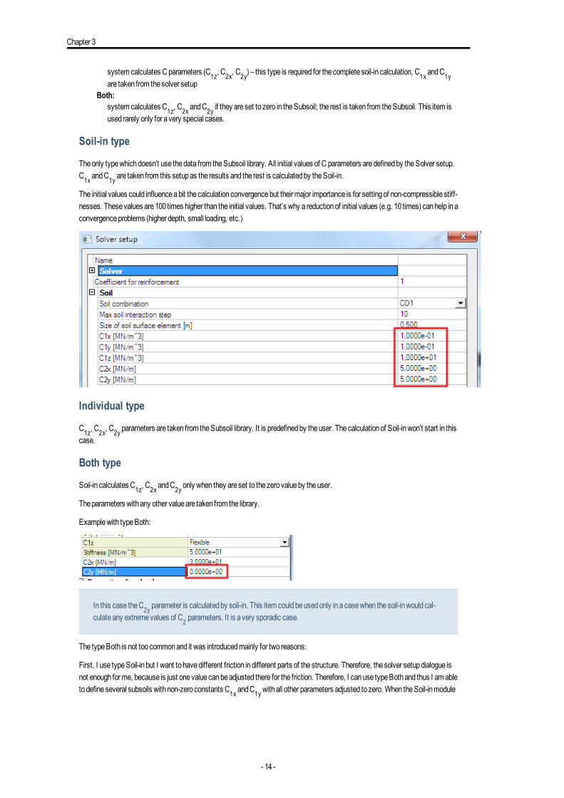
Theonly typewhichdoesn’t use thedata from theSubsoil library. All initial values of C parameters aredefinedby theSolver setup.C1x andC1y are taken from this setupas the results and the rest is calculatedby theSoil-in.
The initial values could influenceabit the calculation convergencebut theirmajor importance is for settingof non-compressible stiff-nesses. Thesevalues are100 times higher than the initial values. That’s why a reductionof initial values (e.g. 10 times) canhelp in aconvergenceproblems (higher depth, small loading, etc.)
Individual type
C1z, C2x, C2y parameters are taken from theSubsoil library. It is predefinedby theuser. Thecalculationof Soil-inwon’t start in thiscase.
Both type
Soil-in calculates C1z, C2x andC2y only when they are set to the zero valueby theuser.
Theparameters with any other valueare taken from the library.
Examplewith typeBoth:
In this case theC2y parameter is calculatedby soil-in. This item could beusedonly in a casewhen the soil-inwould cal-culate any extremevalues of C2 parameters. It is a very sporadic case.
The typeBoth is not too commonand it was introducedmainly for two reasons:
First, I use typeSoil-in but I want to havedifferent friction in different parts of the structure. Therefore, the solver setupdialogue isnot enough forme, because is just one value canbeadjusted there for the friction. Therefore, I canuse typeBothand thus I am ableto define several subsoils with non-zero constants C1x andC1ywith all other parameters adjusted to zero. When theSoil-inmodule
- 14 -

Subsoil in the3Dmodel
runs, thenon-zero constants C1x andC1y areof higher priority than thosedeterminedby the solver andareapplied. Other "zero"values indicate that the values determinedby the solver areapplied.
Second, sometimes it may benecessary to "suppress" higher values of shear (C2x, C2y) calculatedby Soil-inmodule. This mayhappene.g. whenanew plate is modelledonanold oneand theold plate is definedas the first layer of the subsoil. It is a correct andproper solution, but as E modules of soil and concrete aredramatically different, theSoil-inmodule calculates highC2 parameters.Consequently, the stiffness of the foundation slab in themodel is bigger than if the twoslabs were "joined" together and input as ahomogenous monolith. Therefore, C2 parameters may be reducedartificially. This canbeachieved in typeBoth. I define the subsoilwith zeroC1z (it will bedeterminedby theSoil-inmodule) andother non-zeroparameters (C2 and friction). Thus theSoil-inmodulewill provideonly for C1z parameter.
Subsoil libraryThesubsoil contains parameters which canbedefinedby theuser or calculatedby soil-in.
Parameters C1x andC1y arealways definedby theuser.
- 15 -
Chapter 4
Required parameters for Soil-in calculationWhat all must bedefined:
l Project with at least oneboreholewith predefinedgeologic profilel Structurewith surface support typeSoilin or Bothl Loadl Combination typeLinear (ULS or SLS)
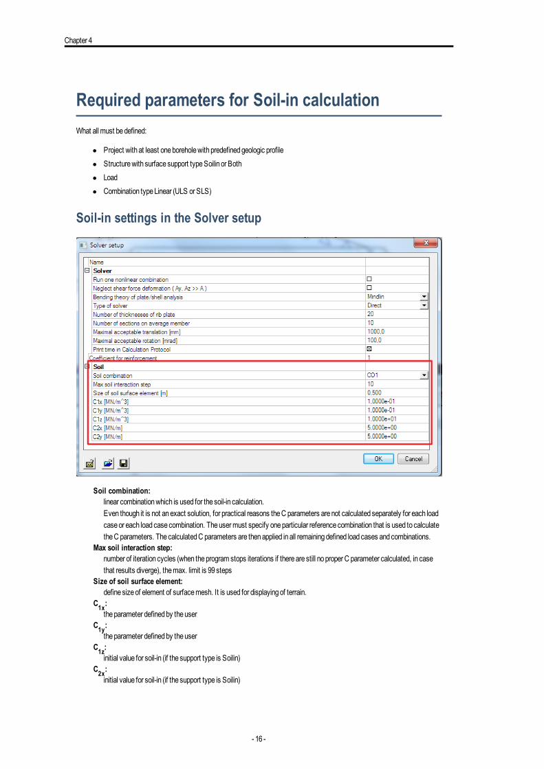
Soil-in settings in the Solver setup
Soil combination:linear combinationwhich is used for the soil-in calculation.Even though it is not anexact solution, for practical reasons theC parameters arenot calculated separately for each loadcaseor each load casecombination. Theusermust specify oneparticular reference combination that is used to calculatetheC parameters. ThecalculatedC parameters are thenapplied in all remainingdefined load cases andcombinations.
Max soil interaction step:number of iteration cycles (when theprogram stops iterations if thereare still no proper C parameter calculated, in casethat results diverge), themax. limit is 99 steps
Size of soil surface element:define sizeof element of surfacemesh. It is used for displayingof terrain.
C1x:theparameter definedby theuser
C1y:theparameter definedby theuser
C1z:initial value for soil-in (if the support type is Soilin)
C2x:initial value for soil-in (if the support type is Soilin)
- 16 -

Requiredparameters for Soil-in calculation
C2y:initial value for soil-in (if the support type is Soilin)
Note: Thesourceof not calculatedparameters depends on the support type. It is described in theprevious chapter.
- 17 -

Chapter 5
Soil-in calculation
Soil-in iterative cycleThevalues from the top structure and the foundationare calculatedby FEM. Thevalues areusedas the sourcedata for the soil-in.
The iterative process is finishedwhen the contact stress σz anddisplacement uz does not changesignificantly in the twosub-sequent iterations. Thespecial quadratic norms areevaluated in theeach iteration cycle to findout if this condition is fulfilled.
Diagram of the iterative cycle:
- 18 -

Soil-in calculation
1. Thevalues are taken from the solver setup, predefinedby theuser.2. Data from the structure and its foundation.3. FEM calculation– important results for soil-in contact stress σz anddisplacement uz.4. The results of i iteration.
- 19 -

Chapter 5
5. Comparisonof the in contact stress σz anduz – it is basedon thequadratic norms, when it does not changesignificantly,
then the calculation is doneandSciaEngineer displays results.6. 1st stepof soil-in – the contact stress is recalculated to thenew loading.7. 2nd stepof soil-in – theC parameters are recalculated, new loading is taken from theprevious step.8. 3rd stepof soil-in – final C parameters from soil-in - thenew input data.9. NewC parameters areused for thenext FEM calculation.
There is amessagewhen the last iteration is done.
Quadratic norm to compare the results from the last and the pre-
vious iterationThecalculationof the settlement of the subsoil and subsequent determinationof theC parameters is performed in a standardwayusingan iterative process. The result of this process is the state inwhich the contact stress or displacement uz in twosubsequentiterations does not changesignificantly. For that reason, the followingquadratic norms areevaluated in every j-th iteration:
Where:
nnumber of nodes
σz,icontact stress in node i
Aiarea corresponding to node i
uz,iglobal displacement of node i in the z-direction
The iterative calculation is stopped if εσ<0,001or εu<0,001
Theory about the derivation processIn this text we limit ourselves to abrief derivation for thepurposeof theexplanation that will follow:
- 20 -
Soil-in calculation
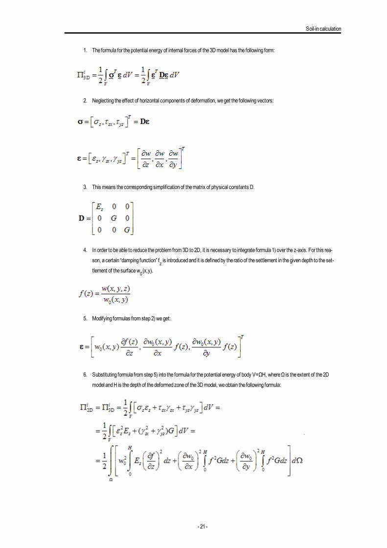
1. The formula for thepotential energy of internal forces of the3Dmodel has the following form:
2. Neglecting theeffect of horizontal components of deformation, weget the following vectors:
3. This means the corresponding simplificationof thematrix of physical constants D.
4. In order to beable to reduce theproblem from 3D to2D, it is necessary to integrate formula1) over the z-axis. For this rea-
son, a certain “damping function” fz is introducedand it is definedby the ratio of the settlement in thegivendepth to the set-
tlement of the surfacew0(x,y).
5. Modifying formulas from step2) weget:
6. Substituting formula from step5) into the formula for thepotential energy of body V=ΩH, whereΩ is theextent of the2D
model andH is thedepthof thedeformedzoneof the3Dmodel, weobtain the following formula:
- 21 -

Chapter 5
7. Integratingover z , weget the formula for thepotential energy of internal forces of the2Dmodel with twoparameters C1S
andC2S:
8. Comparing formulas from step6) and7), wecandefine the relationbetween theparameters of thegeneral (3D) andsur-
face (2D)model:
Conclusion:
It is alsopossible to eliminate theautomatic calculationof someC parameters anddefine themmanually. This canbeachievedbyspecial adjustment of the subsoil parameters andset the type toBoth (!).
- 22 -

The results of soil-in
The results of soil-in
2D data viewerThesoil-in results areavailable in twodifferent services. In the “Calculation, mesh” service is 2D data viewer. Thereare results forSubsoil.
TheC parameters are calculated for themeshon the2Dmember. It is displayedby the colour planes.
The results canbedisplayed for eachof C parameters.
Theexampleof calculatedC1z:
ThepreviewwithC parameters in the table canbealsodisplayed in the2D data viewer.
- 23 -

Chapter 6
ResultsTheservice results contain two result previews:
l Subsoil –C parametersl Subsoil –Other data – this displays settlement (table anddiagram for eachnode)
C parameter results
When theSoilin typeof the support is used then thepreview Subsoil –C parameters displays the same results as 2D data viewer.
When theBoth typeof the support is used then thepreview Subsoil –C parameters displays results of the soilin calculationand the2D data viewer display data from theSubsoil library.
- 24 -

The results of soil-in
Soil stress diagram
The “Subsoil –Other data” allow todisplay Soil structure strengthdiagram for calculatedpoints. Thepoints aredisplayedby theactionbutton “Soil stress diagram”.
Greenvertexes on theplate are centres of elements from 2Dmesh. Twogreenvertexes outside theplate are insertingpoints fromboreholes.
Points aredisplayedas agreenvertex. Thevertical axial components of stress and the structure strength (consequently thedepthof thedeformedsubsoil zone) canbedisplayed for all points from the2Dmeshand for the insertingpoints of theboreholes. Userjust selects thepoint and thediagram is displayed.
If theborehole is definedas “Results only”, then thepoint is available for displaying thediagram.
Exampleof thedialogueSoil StructureStrength:
- 25 -

Chapter 6
Previous:Display theSoil StructureStrength for theprevious node
Next:Display theSoil StructureStrength for thenext node
Borehole:Display theSoil StructureStrength for the selectedborehole insertingpoint
Soil point:Nodenumber
Settlement table
The table is displayed in theSubsoil – other data results. Thepreview table contain values w for eachnode.
Thesettlement w is different from displacement uz of the foundationplate becausew is calculatedwithout stiffness of structure andfrom thepenultimate iteration. Therefore it is useful towatch values w only outside the foundation.
- 26 -

The results of soil-in
Results for each iteration cycleWhen the soil-inwon’t finish its iterationprocess in a standardway, the calculationends after thepredefinednumber of cycles (thesolver setup). User candisplay the contact stresses on theplate for each cycle separately sohe is able to find theproblem.
Thecalculated contact stresses for each iteration cycle canbe found in the results.
The first iteration cycle
- 27 -

Chapter 6
The second iteration cycle
The third iteration cycle
The fourth iteration cycle
- 28 -

The results of soil-in
- 29 -

Chapter 7
Soil-in and Pile designSoil-in is a tool for calculation stiffness of the subsoil half-space. Thepile is a typeof support. Soil-in andpiles canbeused in oneproject and systemwill calculate it together.
Soil-in andPiles areusing twodifferent types of boreholes. Piles arebasedon theCPT profiles; soil-in boreholes areuser-definedby layers. Both types of boreholes must be inserted in theproject if theuser wants to calculate soil-in andpile design.
1. Borehole profile for soil-in2. Surface support for soil-in3. Piles for Pile design4. CPT profile for Pile design
- 30 -

Advanced tips
Advanced tips
The effect of the subsoil outside the structureThenearest subsoil around the loadedstructure is alsoaffectedby its settlement. Thebetter realistic picture how it works in the real-ity is displayedbelow.
Calculationof thenearest surroundingof the structure is a specific use case. It is recommended toaddonemoreplate to the struc-ture for this purpose–additional subsoil element.
Thenew plate should be insertedwith theminimum thickness (e.g. 0,01mm) andplacednext to the foundation.
TheC parameters for this affected subsoil around the structure are calculated this way also.
Thedeformedsubsoil calculatedby theSciaEngineer:
CalculatedC parameters:
- 31 -

Chapter 8
Thestructure is markedby theblack rectangle andaround this is onemoreplate - surroundingplate –with thickness 0,001mm.
Automatic calculation of the edge supports
Whenuser don’t useany subsoil elements then theprogramwill eliminate theneglect of the subsoil onedges by anautomatic insert-ingof vertical supports on the foundationedges.
Thecalculationof those supports is basedonalready knownC parameters. Theprogram try to support theplate in the sameway asit should be supportedby the subsoil itself. This leads to approximatemodel where the sumof reaction is contact stress with reac-tions in thosenodes.
This solution canbesometimes undesirable –e.g. if there is a second foundationnear by the calculatedoneor there is someothersupport under or near the foundationedge.
This automatic input canbeavoidedmanually. User can insert a springwith a small stiffness on theplate edges and then the sys-temwon’t useautomatic input of vertical supports. This could be theadditional subsoil elements.
Pad foundation and soil-inThepad foundation is not connectedwith the soil-in calculation.
How tousesoil-in for thepad foundation check:
- 32 -

Advanced tips
1. Createadditional structure to calculate theC parameters in thenearest surrounding (it is described in theprevious tip)
CalculatedC parameters on the surroundingplate –> C parameters for thepad foundation
2. CalculatedC parameters canbeused in theSubsoil library. Put the values from the table to theSubsoil library.
- 33 -

Chapter 8
3. Run the linear calculationagain.4. Check thepad foundation in a standardway.
What if the model is correct but the iteration is not finishedSometimes themodel is correct but somecircumstances may causeunfinished iterative process. The results in cycles don’t leadto oneset of C parameters but on the contrary, the results aremoreandmoredifferent.
This canbecausedby some tensions in the foundationplate, specific foundationmembers andsimilar problems.
How to solve thoseproblems:
1. It is necessary to check themodel. It must be correct – themeshelements arenot triangular, theelement´s Z axis is
upward, the foundationplatemust beunder the soil surfaceandsoon.2. Check the iteration cycles in results – contact stresses, typeof loads – soilin iteration.
First few iteration cycles will beprobably quiteOK andafter some time the results becomemessy.
Findonecycle (between those correct ones) where the results seem tobeclose to the reality – e.g. 5thcycle. Use this
value in the solver setup for number of iteration cycles.
3. Start the linear calculationagain, it will be finishedafter the5th iteration cyclewith results most closest to the reality.
Thecorrect cycle is between2nd and5th cycle in themost cases.
- 34 -

TutorialSoil-In - Additional plates

Chapter 1
Table of Contents
Tutorial 1
Table of Contents 2
Tutorial - additional plates 3
Introduction 4
How to calculate the plate without soilin 7
How to calculate the plate with soilin. 10
How to create the additional plates around 15
- 2 -

Tutorial - additional plates
Tutorial - additional plates
- 3 -

Chapter 1
IntroductionSoilin is a tool which calculates C parameters of the subsoil under the surface support. Using theadditional plates around the sup-port provides more realistic results.
About C parameters:
1) C parameters areparameters of interaction, so their valuedepends on the structure, load, stiffness andsubsoil. Change in any ofthoseparts causes different C parameters.
2) Thewhole plate is supported vertically by the soil stiffness –parameter C1 (winkler) andalso in the shear direction–parameterC2 (pasternak).
3) Theplate edges aremore supportedby theC2 parameters because it is affectedby neglecting.
4) Theareaaround the support is affectedby the shear stiffness of the soil and thedegreasebasin is created.
5) Thedegreasebasin canbesubstitutedby spring supports around theplate – this is doneautomatically inSciaEngineer whenuser don’t addplates around.
6)Whenuser uses theplates around the support, the springs arenot addedand theC parameters are calculated for thewhole area.
-> This tutorial describes how to create plates around the support - additional plates.
Settings for soilin calculation
1. The functionality Subsoil andSoil iterationmust be checked.
2. Onecombinationmust be linear - this combination is used for soilin calculation.
- 4 -

Introduction
3. This linear combinationmust be selected inSolver setup to run soilinwith it.
4. Theproject must contain boreholewith geologic profile.
- 5 -

Chapter 1
5. Theproject must contain surface support type soilin.
- 6 -

How to calculate theplatewithout soilin
How to calculate the plate without soilin1. Open theproject “soilin_start.esa”.
2. There is oneplatewith the surface support type Individual. This typeof the support has a constant parameters C1 andC2.
3. Run the linear calculationwith thedefault settings.
- 7 -

Chapter 1
4. Go to the serviceResults. Display the results for internal forces. Thereareno results for C parameters.5. Internal forces - for example vy:
- 8 -

How to calculate theplatewithout soilin
- 9 -

Chapter 1
How to calculate the plate with soilin.1. Change the support type to soilin.2. Run the linear calculationagain.3. Go to the serviceResults. Display the results for internal forces andsoilin for combinationC01.
4. Internal forces - vy:
- 10 -

How to calculate theplatewith soilin.
5. Subsoil - C parameters - parameter C1z:
- 11 -

Chapter 1
6. Subsoil - Other data (see thepreviewwith the table for the settlement):
- 12 -

How to calculate theplatewith soilin.
7. Subsoil - Other data - use theactionbutton "Soil Stress Diagram"andselect onegreenvertex:
8. A new dialogueappears - there is a stress diagram for the selectedmeshelement:
- 13 -

Chapter 1
9. Close thedialogue.10. UseESC to finish theaction.
Theedges of theplate are supportedby springs automatically.
- 14 -

How to create theadditional plates around
How to create the additional plates around1. Use the sameproject.2. Open theStructure serviceandstart the command for insertinganew plate.3. Set the thickness of theplate to 1mm.4. Create4plates around the surface support according to thepicture. Thewidth from theoriginal plate is 3m.
5. Add the surface support type soilin on thoseplates.
- 15 -

Chapter 1
6. Run the linear calculationwith the samesettings again.7. Go to the serviceResults. Display the results for soilin.8. Subsoil - C parameters - parameter C1z:
9. Subsoil - Other data (see thepreviewwith the table for settlement):
- 16 -

How to create theadditional plates around
10. Subsoil - Other data - use theactionbutton "Soil Stress Diagram"andselect onegreenvertex:
- 17 -

Chapter 1
11. Stress diagram for selectedmeshelement:
12. Close thedialogue.13. UseESC to finish theaction.14. The interesting results aredeformations.15. See the result "Displacement of nodes", valueUz onDeformedstructure:
Thedeformedstructure shows thedegreasebasin.
- 18 -

How to create theadditional plates around
16. The result is in project "soilin_finished.esa".
- 19 -

